WO2017150501A1 - ジャーナル軸受および回転機械 - Google Patents
ジャーナル軸受および回転機械 Download PDFInfo
- Publication number
- WO2017150501A1 WO2017150501A1 PCT/JP2017/007679 JP2017007679W WO2017150501A1 WO 2017150501 A1 WO2017150501 A1 WO 2017150501A1 JP 2017007679 W JP2017007679 W JP 2017007679W WO 2017150501 A1 WO2017150501 A1 WO 2017150501A1
- Authority
- WO
- WIPO (PCT)
- Prior art keywords
- rotor shaft
- journal bearing
- guide metal
- bearing
- axial direction
- Prior art date
- Legal status (The legal status is an assumption and is not a legal conclusion. Google has not performed a legal analysis and makes no representation as to the accuracy of the status listed.)
- Ceased
Links
Images

Classifications
-
- F—MECHANICAL ENGINEERING; LIGHTING; HEATING; WEAPONS; BLASTING
- F16—ENGINEERING ELEMENTS AND UNITS; GENERAL MEASURES FOR PRODUCING AND MAINTAINING EFFECTIVE FUNCTIONING OF MACHINES OR INSTALLATIONS; THERMAL INSULATION IN GENERAL
- F16C—SHAFTS; FLEXIBLE SHAFTS; ELEMENTS OR CRANKSHAFT MECHANISMS; ROTARY BODIES OTHER THAN GEARING ELEMENTS; BEARINGS
- F16C33/00—Parts of bearings; Special methods for making bearings or parts thereof
- F16C33/72—Sealings
- F16C33/74—Sealings of sliding-contact bearings
- F16C33/741—Sealings of sliding-contact bearings by means of a fluid
- F16C33/748—Sealings of sliding-contact bearings by means of a fluid flowing to or from the sealing gap, e.g. vacuum seals with differential exhaust
-
- F—MECHANICAL ENGINEERING; LIGHTING; HEATING; WEAPONS; BLASTING
- F01—MACHINES OR ENGINES IN GENERAL; ENGINE PLANTS IN GENERAL; STEAM ENGINES
- F01D—NON-POSITIVE DISPLACEMENT MACHINES OR ENGINES, e.g. STEAM TURBINES
- F01D25/00—Component parts, details, or accessories, not provided for in, or of interest apart from, other groups
- F01D25/16—Arrangement of bearings; Supporting or mounting bearings in casings
- F01D25/166—Sliding contact bearing
-
- F—MECHANICAL ENGINEERING; LIGHTING; HEATING; WEAPONS; BLASTING
- F01—MACHINES OR ENGINES IN GENERAL; ENGINE PLANTS IN GENERAL; STEAM ENGINES
- F01D—NON-POSITIVE DISPLACEMENT MACHINES OR ENGINES, e.g. STEAM TURBINES
- F01D25/00—Component parts, details, or accessories, not provided for in, or of interest apart from, other groups
- F01D25/16—Arrangement of bearings; Supporting or mounting bearings in casings
-
- F—MECHANICAL ENGINEERING; LIGHTING; HEATING; WEAPONS; BLASTING
- F01—MACHINES OR ENGINES IN GENERAL; ENGINE PLANTS IN GENERAL; STEAM ENGINES
- F01D—NON-POSITIVE DISPLACEMENT MACHINES OR ENGINES, e.g. STEAM TURBINES
- F01D25/00—Component parts, details, or accessories, not provided for in, or of interest apart from, other groups
- F01D25/18—Lubricating arrangements
-
- F—MECHANICAL ENGINEERING; LIGHTING; HEATING; WEAPONS; BLASTING
- F01—MACHINES OR ENGINES IN GENERAL; ENGINE PLANTS IN GENERAL; STEAM ENGINES
- F01D—NON-POSITIVE DISPLACEMENT MACHINES OR ENGINES, e.g. STEAM TURBINES
- F01D25/00—Component parts, details, or accessories, not provided for in, or of interest apart from, other groups
- F01D25/18—Lubricating arrangements
- F01D25/183—Sealing means
- F01D25/186—Sealing means for sliding contact bearing
-
- F—MECHANICAL ENGINEERING; LIGHTING; HEATING; WEAPONS; BLASTING
- F02—COMBUSTION ENGINES; HOT-GAS OR COMBUSTION-PRODUCT ENGINE PLANTS
- F02C—GAS-TURBINE PLANTS; AIR INTAKES FOR JET-PROPULSION PLANTS; CONTROLLING FUEL SUPPLY IN AIR-BREATHING JET-PROPULSION PLANTS
- F02C7/00—Features, components parts, details or accessories, not provided for in, or of interest apart form groups F02C1/00 - F02C6/00; Air intakes for jet-propulsion plants
- F02C7/06—Arrangements of bearings; Lubricating
-
- F—MECHANICAL ENGINEERING; LIGHTING; HEATING; WEAPONS; BLASTING
- F16—ENGINEERING ELEMENTS AND UNITS; GENERAL MEASURES FOR PRODUCING AND MAINTAINING EFFECTIVE FUNCTIONING OF MACHINES OR INSTALLATIONS; THERMAL INSULATION IN GENERAL
- F16C—SHAFTS; FLEXIBLE SHAFTS; ELEMENTS OR CRANKSHAFT MECHANISMS; ROTARY BODIES OTHER THAN GEARING ELEMENTS; BEARINGS
- F16C17/00—Sliding-contact bearings for exclusively rotary movement
- F16C17/02—Sliding-contact bearings for exclusively rotary movement for radial load only
-
- F—MECHANICAL ENGINEERING; LIGHTING; HEATING; WEAPONS; BLASTING
- F16—ENGINEERING ELEMENTS AND UNITS; GENERAL MEASURES FOR PRODUCING AND MAINTAINING EFFECTIVE FUNCTIONING OF MACHINES OR INSTALLATIONS; THERMAL INSULATION IN GENERAL
- F16C—SHAFTS; FLEXIBLE SHAFTS; ELEMENTS OR CRANKSHAFT MECHANISMS; ROTARY BODIES OTHER THAN GEARING ELEMENTS; BEARINGS
- F16C17/00—Sliding-contact bearings for exclusively rotary movement
- F16C17/02—Sliding-contact bearings for exclusively rotary movement for radial load only
- F16C17/03—Sliding-contact bearings for exclusively rotary movement for radial load only with tiltably-supported segments, e.g. Michell bearings
-
- F—MECHANICAL ENGINEERING; LIGHTING; HEATING; WEAPONS; BLASTING
- F16—ENGINEERING ELEMENTS AND UNITS; GENERAL MEASURES FOR PRODUCING AND MAINTAINING EFFECTIVE FUNCTIONING OF MACHINES OR INSTALLATIONS; THERMAL INSULATION IN GENERAL
- F16C—SHAFTS; FLEXIBLE SHAFTS; ELEMENTS OR CRANKSHAFT MECHANISMS; ROTARY BODIES OTHER THAN GEARING ELEMENTS; BEARINGS
- F16C33/00—Parts of bearings; Special methods for making bearings or parts thereof
- F16C33/02—Parts of sliding-contact bearings
- F16C33/04—Brasses; Bushes; Linings
- F16C33/06—Sliding surface mainly made of metal
- F16C33/10—Construction relative to lubrication
-
- F—MECHANICAL ENGINEERING; LIGHTING; HEATING; WEAPONS; BLASTING
- F16—ENGINEERING ELEMENTS AND UNITS; GENERAL MEASURES FOR PRODUCING AND MAINTAINING EFFECTIVE FUNCTIONING OF MACHINES OR INSTALLATIONS; THERMAL INSULATION IN GENERAL
- F16C—SHAFTS; FLEXIBLE SHAFTS; ELEMENTS OR CRANKSHAFT MECHANISMS; ROTARY BODIES OTHER THAN GEARING ELEMENTS; BEARINGS
- F16C33/00—Parts of bearings; Special methods for making bearings or parts thereof
- F16C33/02—Parts of sliding-contact bearings
- F16C33/04—Brasses; Bushes; Linings
- F16C33/06—Sliding surface mainly made of metal
- F16C33/10—Construction relative to lubrication
- F16C33/1025—Construction relative to lubrication with liquid, e.g. oil, as lubricant
-
- F—MECHANICAL ENGINEERING; LIGHTING; HEATING; WEAPONS; BLASTING
- F16—ENGINEERING ELEMENTS AND UNITS; GENERAL MEASURES FOR PRODUCING AND MAINTAINING EFFECTIVE FUNCTIONING OF MACHINES OR INSTALLATIONS; THERMAL INSULATION IN GENERAL
- F16C—SHAFTS; FLEXIBLE SHAFTS; ELEMENTS OR CRANKSHAFT MECHANISMS; ROTARY BODIES OTHER THAN GEARING ELEMENTS; BEARINGS
- F16C33/00—Parts of bearings; Special methods for making bearings or parts thereof
- F16C33/02—Parts of sliding-contact bearings
- F16C33/04—Brasses; Bushes; Linings
- F16C33/06—Sliding surface mainly made of metal
- F16C33/10—Construction relative to lubrication
- F16C33/1025—Construction relative to lubrication with liquid, e.g. oil, as lubricant
- F16C33/1045—Details of supply of the liquid to the bearing
-
- F—MECHANICAL ENGINEERING; LIGHTING; HEATING; WEAPONS; BLASTING
- F16—ENGINEERING ELEMENTS AND UNITS; GENERAL MEASURES FOR PRODUCING AND MAINTAINING EFFECTIVE FUNCTIONING OF MACHINES OR INSTALLATIONS; THERMAL INSULATION IN GENERAL
- F16C—SHAFTS; FLEXIBLE SHAFTS; ELEMENTS OR CRANKSHAFT MECHANISMS; ROTARY BODIES OTHER THAN GEARING ELEMENTS; BEARINGS
- F16C33/00—Parts of bearings; Special methods for making bearings or parts thereof
- F16C33/02—Parts of sliding-contact bearings
- F16C33/04—Brasses; Bushes; Linings
- F16C33/06—Sliding surface mainly made of metal
- F16C33/10—Construction relative to lubrication
- F16C33/1025—Construction relative to lubrication with liquid, e.g. oil, as lubricant
- F16C33/106—Details of distribution or circulation inside the bearings, e.g. details of the bearing surfaces to affect flow or pressure of the liquid
- F16C33/1085—Channels or passages to recirculate the liquid in the bearing
-
- F—MECHANICAL ENGINEERING; LIGHTING; HEATING; WEAPONS; BLASTING
- F05—INDEXING SCHEMES RELATING TO ENGINES OR PUMPS IN VARIOUS SUBCLASSES OF CLASSES F01-F04
- F05D—INDEXING SCHEME FOR ASPECTS RELATING TO NON-POSITIVE-DISPLACEMENT MACHINES OR ENGINES, GAS-TURBINES OR JET-PROPULSION PLANTS
- F05D2220/00—Application
- F05D2220/30—Application in turbines
- F05D2220/31—Application in turbines in steam turbines
-
- F—MECHANICAL ENGINEERING; LIGHTING; HEATING; WEAPONS; BLASTING
- F05—INDEXING SCHEMES RELATING TO ENGINES OR PUMPS IN VARIOUS SUBCLASSES OF CLASSES F01-F04
- F05D—INDEXING SCHEME FOR ASPECTS RELATING TO NON-POSITIVE-DISPLACEMENT MACHINES OR ENGINES, GAS-TURBINES OR JET-PROPULSION PLANTS
- F05D2220/00—Application
- F05D2220/30—Application in turbines
- F05D2220/32—Application in turbines in gas turbines
-
- F—MECHANICAL ENGINEERING; LIGHTING; HEATING; WEAPONS; BLASTING
- F05—INDEXING SCHEMES RELATING TO ENGINES OR PUMPS IN VARIOUS SUBCLASSES OF CLASSES F01-F04
- F05D—INDEXING SCHEME FOR ASPECTS RELATING TO NON-POSITIVE-DISPLACEMENT MACHINES OR ENGINES, GAS-TURBINES OR JET-PROPULSION PLANTS
- F05D2240/00—Components
- F05D2240/50—Bearings
- F05D2240/54—Radial bearings
-
- F—MECHANICAL ENGINEERING; LIGHTING; HEATING; WEAPONS; BLASTING
- F05—INDEXING SCHEMES RELATING TO ENGINES OR PUMPS IN VARIOUS SUBCLASSES OF CLASSES F01-F04
- F05D—INDEXING SCHEME FOR ASPECTS RELATING TO NON-POSITIVE-DISPLACEMENT MACHINES OR ENGINES, GAS-TURBINES OR JET-PROPULSION PLANTS
- F05D2240/00—Components
- F05D2240/55—Seals
-
- F—MECHANICAL ENGINEERING; LIGHTING; HEATING; WEAPONS; BLASTING
- F05—INDEXING SCHEMES RELATING TO ENGINES OR PUMPS IN VARIOUS SUBCLASSES OF CLASSES F01-F04
- F05D—INDEXING SCHEME FOR ASPECTS RELATING TO NON-POSITIVE-DISPLACEMENT MACHINES OR ENGINES, GAS-TURBINES OR JET-PROPULSION PLANTS
- F05D2260/00—Function
- F05D2260/98—Lubrication
-
- F—MECHANICAL ENGINEERING; LIGHTING; HEATING; WEAPONS; BLASTING
- F16—ENGINEERING ELEMENTS AND UNITS; GENERAL MEASURES FOR PRODUCING AND MAINTAINING EFFECTIVE FUNCTIONING OF MACHINES OR INSTALLATIONS; THERMAL INSULATION IN GENERAL
- F16C—SHAFTS; FLEXIBLE SHAFTS; ELEMENTS OR CRANKSHAFT MECHANISMS; ROTARY BODIES OTHER THAN GEARING ELEMENTS; BEARINGS
- F16C2360/00—Engines or pumps
-
- F—MECHANICAL ENGINEERING; LIGHTING; HEATING; WEAPONS; BLASTING
- F16—ENGINEERING ELEMENTS AND UNITS; GENERAL MEASURES FOR PRODUCING AND MAINTAINING EFFECTIVE FUNCTIONING OF MACHINES OR INSTALLATIONS; THERMAL INSULATION IN GENERAL
- F16C—SHAFTS; FLEXIBLE SHAFTS; ELEMENTS OR CRANKSHAFT MECHANISMS; ROTARY BODIES OTHER THAN GEARING ELEMENTS; BEARINGS
- F16C2380/00—Electrical apparatus
- F16C2380/26—Dynamo-electric machines or combinations therewith, e.g. electro-motors and generators
Definitions
- the present disclosure relates to a journal bearing and a rotary machine for rotatably supporting a rotor shaft.
- journal bearings are known as bearing devices used in rotating machines such as steam turbines and gas turbines.
- Patent Document 1 describes a journal bearing that supports a rotor shaft by a plurality of bearing pads.
- the journal bearing of Patent Document 1 includes a carrier ring, an upstream bearing pad and a downstream bearing pad supported by the carrier ring, and a plurality of lubricant oils supplied between each bearing pad and the rotor shaft.
- the plurality of oil supply nozzles include a first oil supply nozzle (uppermost nozzle) disposed upstream of the upstream bearing pad, and second and third oil supply nozzles disposed at both ends of the upstream bearing pad.
- Patent Document 1 also describes a configuration including a pair of guide metals that are spaced apart from each other in the axial direction on the inner peripheral side of the upper half carrier ring for the purpose of preventing the rotor shaft from jumping up. Has been.
- At least one embodiment of the present invention provides a journal bearing and a rotating machine that can maintain a balance of load capacity among a plurality of bearing pads, prevent occurrence of abnormal vibration, and improve bearing performance.
- the purpose is to provide.
- a journal bearing includes: With carrier ring, A plurality of bearing pads provided on the inner peripheral side of the lower half region of the carrier ring and configured to support the rotor shaft from below; A guide metal disposed in the upper half region of the carrier ring and provided at the center in the axial direction of the rotor shaft so as to cover the upper region of the outer peripheral surface of the rotor shaft; Is provided.
- the cause of the lack of the oil film pressure between the first bearing pad located on the most upstream side and the rotor shaft is that the air to the lubricating oil carried over to the first bearing pad
- there was contamination That is, as in the configuration of (2) above, between the inner peripheral surface of each side plate and the outer peripheral surface of the rotor shaft, the bearing inner space surrounded by the pair of side plates and the outer bearing are communicated.
- the journal bearing having the gap (side plate gap) the air sucked from the gap in the region from the second bearing pad arranged on the downstream side to the first bearing pad can be mixed into the lubricating oil.
- the lubricating oil carried over to the first bearing pad contains a large amount of air, and the actual amount of lubricating oil is small. Therefore, even if the amount of oil discharged from the oil supply unit immediately upstream of the first bearing pad and the oil supply unit immediately upstream of the second bearing pad are the same, the first bearing pad has a larger amount than the second bearing pad. Prone to lack of lubricating oil.
- the lubricating oil is an incompressible fluid, the air contained in the lubricating oil is a compressive fluid. Therefore, the air bubbles contained in the lubricating oil in the first bearing pad on the upstream side (particularly near the front edge).
- the semi-annular space sandwiched between the pair of guide metals provided in the upper half region of the carrier ring becomes negative pressure as the rotor shaft rotates, and the guide metal and the rotor shaft
- the inflow of outside air into the semi-annular space through a minute gap between the outer peripheral surface and the outer peripheral surface is one of the causes of air mixing into the carry-over oil. That is, outside air flowing into the semi-annular space between the guide metals in the upper half region of the carrier ring is mixed into the oil (oil attached to the outer peripheral surface of the rotor shaft or the inner peripheral surface of the guide metal) existing in the minute gap.
- the journal bearing (1) is provided in the upper half region of the carrier ring, and includes a guide metal provided at the center in the axial direction of the rotor shaft so as to cover the upper region of the outer peripheral surface of the rotor shaft. It is configured. Therefore, unlike the case where a pair of guide metals is provided, there is no negative pressure space (semi-annular space between the pair of guide metals) that causes air mixing into the carryover oil, and the carryover contains a lot of air. The generation of oil can be suppressed. Therefore, even when the side plate gap for communicating the bearing internal space and the outside is provided as in the configuration of (2) above, the load capacity balance between the plurality of bearing pads is appropriately adjusted. Therefore, the occurrence of abnormal vibration in the journal bearing can be prevented and the bearing performance can be improved.
- It further includes a dam provided on the downstream side of the guide metal and having a larger width along the axial direction than the guide metal.
- the guide metal and the dam are integrally formed, and the guide metal and the dam are continuously provided. There is no space where air can enter the over oil. For this reason, generation of carry-over oil containing air can be effectively prevented.
- the width W G_TE along the axial direction of the downstream end of the dam is W G_TE ⁇ 0 when the width in the axial direction of the first bearing pad on the most upstream side among the plurality of bearing pads is W P1. .8 ⁇ W P1 is satisfied.
- the width W G_TE along the axial direction of the downstream end of the dam since the 0.8 times or more the width W P1 in the axial direction of the first bearing pad on the most upstream side
- the dam can reliably reduce the carry-over oil that reaches the first bearing pad through both sides of the guide metal.
- the dam includes a pair of rectifying sections that form both ends of the dam in the axial direction and are configured to guide carry-over oil from the upstream side toward the outside in the axial direction.
- each of the rectifying units is inclined with respect to the rotational direction of the rotor shaft so as to go outward in the axial direction as going downstream.
- the leading edge of the rectifying unit is inclined with respect to the rotation direction of the rotor shaft so as to go outward in the axial direction toward the downstream side. Is smoothly turned along the straightening portion, and the carry-over oil can be smoothly discharged to the outside of the bearing.
- the guide metal is formed with at least one oil supply opening configured to open to a surface of the guide metal facing the rotor shaft and to supply lubricating oil to the surface of the guide metal.
- the lubricating oil is supplied to the surface of the guide metal through the oil supply port provided on the surface of the guide metal facing the rotor shaft, the guide metal and the rotor shaft It is possible to maintain the lubricity between them when they come into contact with each other. Further, it is considered that the lubricating oil supplied from the oil supply port to the minute gap between the guide metal and the outer peripheral surface of the rotor shaft flows downstream through the minute gap without coming into contact with air. Therefore, unlike the carry-over oil that goes to the downstream side through the both sides of the guide metal, the lubricating oil from the oil supply port is less likely to be mixed in with air.
- an oil supply port is provided on the surface of the guide metal, and lubricating oil is supplied from the oil supply port, so that air is supplied to the most upstream pad located downstream of the guide metal. Lubricating oil with low risk of contamination can be supplied.
- the at least one oil supply port is located on the uppermost part of the guide metal or on the downstream side of the uppermost part.
- a rotating machine includes: The journal bearing according to any one of (1) to (9) above; A rotor shaft supported by the journal bearing; Is provided.
- the guide metal since the guide metal is provided in the center in the axial direction of the rotor shaft, unlike the case of providing a pair of guide metals, it causes air mixing into the carryover oil. There is no negative pressure space (annular space between a pair of guide metals), and it is possible to suppress the generation of carry-over oil containing a large amount of air. Therefore, even when there is a side plate gap for communicating between the bearing internal space and the outside, the load capacity balance between the plurality of bearing pads can be maintained appropriately, and abnormal vibration in the journal bearing can be maintained. Can be prevented and bearing performance can be improved.
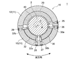
- FIG. 2 is a sectional view taken along line AA in FIG. 1.
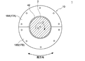
- FIG. 3 is a view taken along line BB in FIG. 1.
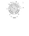
- FIG. 2 is a development view of an upper half region of the journal bearing according to the embodiment (a development view in which the journal bearing shown in FIG. 1 is viewed from the C direction). It is sectional drawing which shows the guide metal and oil filler opening in one Embodiment.
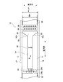
- FIG. 1 is a cross-sectional view along the axial direction of a journal bearing 10 according to an embodiment.
- 2 is a cross-sectional view taken along line AA in FIG.
- FIG. 3 is a view taken along the line BB in FIG.
- the “axial direction” is the direction of the central axis O of the rotor shaft 2 supported by the journal bearing 10
- the “radial direction” is the radial direction of the rotor shaft 2
- the “circumferential direction”. Is the circumferential direction of the rotor shaft 2.
- the “circumferential direction” may be the circumferential direction of the carrier rings 12 and 13 or the circumferential direction of the side plates 17 and 18.
- upstream side” or “downstream side” refers to an upstream side or a downstream side in the rotation direction of the rotor shaft 2.
- the journal bearing 10 employs a direct lubrication system as a lubrication system (oil supply system), and the first bearing pad 30 and the second bearing pad are disposed in the lower half region of the carrier ring 11. 32 is arranged.
- the journal bearing 10 is a tilting pad bearing.
- the front edge 30a of the first bearing pad 30 is located on the upstream side, and the rear edge 30b is located on the downstream side.
- the front edge 32a of the second bearing pad 32 is located on the upstream side, and the rear edge 32b is located on the downstream side.
- the illustrated journal bearing 10 will be described as an example, but the journal bearing 10 according to the present embodiment is not limited to this configuration.
- a configuration in which three or more bearing pads are attached to the lower half region of the carrier ring 11 may be employed.
- the journal bearing 10 is provided on the inner peripheral side of the carrier ring 11 and the lower half region of the carrier ring 11, and a plurality of bearing pads 30 configured to support the rotor shaft 2 from below. , 32 and a pair of side plates 17, 18 provided on both sides of the plurality of bearing pads 30, 32 in the axial direction of the rotor shaft 2.
- the carrier ring 11 is supported by a bearing casing (not shown) and includes an upper half carrier ring 12 and a lower half carrier ring 13.
- Each of the upper half carrier ring 12 and the lower half carrier ring 13 has an inner circumferential surface and an outer circumferential surface such that a cross section perpendicular to the axial direction is a semicircular arc shape.
- the carrier ring 11 is divided into an upper half carrier ring 12 and a lower half carrier ring 13.
- the carrier ring 11 may be an integral structure, or 3 The structure divided
- an area above the horizontal plane passing through the central axis O is referred to as an upper area, and a lower area is referred to as a lower area.
- a pair of side plates 17 and 18 are disposed along the outer periphery of the rotor shaft 2 on both ends of the carrier ring 11 in the axial direction.
- the side plates 17 and 18 are formed in a disc shape, and a hole through which the rotor shaft 2 passes is formed in the center.
- the side plates 17 and 18 may have a half structure including upper half side plates 17A and 18A and lower half side plates 17B and 18B. These side plates 17 and 18 moderately prevent leakage of lubricating oil supplied from oil supply units 25 to 29 described later.
- the upper half carrier ring 12 and the lower half carrier ring 13 are provided with at least one oil supply unit 25 to 29.
- the oil supply units 25 to 29 are oil supply nozzles.
- a total of five oil supply units including three oil supply units 27, a fourth oil supply unit 28, and a fifth oil supply unit 29 are provided.
- the 1st oil supply unit 25 and the 2nd oil supply unit 26 are arrange
- the third oil supply unit 27 and the fourth oil supply unit 28 are arranged side by side in the circumferential direction between the first bearing pad 30 and the second bearing pad 32 located on the downstream side of the first bearing pad 30. ing.
- the fifth oil supply unit 29 is arranged on the downstream side of the second bearing pad 32.
- the fifth oil supply unit 29 may have a first injection hole 29 a and a second injection hole 29 b having different lubricating oil injection directions.
- the first injection hole 29 a is configured to inject lubricating oil upstream toward the second bearing pad 32 for the purpose of cooling the second bearing pad (most downstream pad) 32.
- the second injection hole 29b is configured to inject lubricating oil toward the guide metal 20 on the downstream side for the purpose of maintaining lubricity when the guide metal 20 and the rotor shaft 2 described later come into contact with each other.
- a lubricating oil supply path (not shown) is formed inside the carrier ring 11.
- the lubricating oil supplied to the lubricating oil supply path is sent to each of the oil supply units 25 to 29 and is jetted from the oil supply units 25 to 29 to the vicinity of the bearing pads 30 and 32.
- the 1st bearing pad 30 and the 2nd bearing pad 32 are provided in the inner peripheral side of the lower half carrier ring 13, and are comprised so that the rotor shaft 2 may be supported from the downward direction.
- the first bearing pad 30 is provided along the outer periphery of the rotor shaft 2 on the inner peripheral side of the lower half carrier ring 13.
- the second bearing pad 32 is provided along the outer periphery of the rotor shaft 2 on the inner peripheral side of the lower half carrier ring 13 and downstream of the first bearing pad 30 in the rotational direction S of the rotor shaft 2.
- the first bearing pad 30 and the second bearing pad 32 are provided on the lower half carrier ring 13, the rotor shaft 2 can be appropriately supported by the first bearing pad 30 and the second bearing pad 32.
- the carrier ring 11 is not a structure divided into the upper half carrier ring 12 and the lower half carrier ring 13 but is an integral structure, or a structure divided into three or more, the first bearing pad 30.
- the second bearing pad 32 may be provided in the lower half region of the carrier ring 11.
- FIG. 1 is a development view of the upper half region of the journal bearing 10 according to the embodiment (a development view of the journal bearing 10 shown in FIG. 1 viewed from the C direction).
- FIG. 5 is a cross-sectional view showing the guide metal 20 and the fuel filler opening 60 in one embodiment.
- the journal bearing 10 is disposed in the upper half region of the carrier ring 11 (the upper half carrier ring 12 in the illustrated example) and the rotor.
- a guide metal (semi-annular bearing portion) 20 provided at the center in the axial direction of the rotor shaft 2 is provided so as to cover the upper region of the outer peripheral surface of the shaft 2.
- the journal bearing 10 includes a single guide metal 20 that is provided at the center in the axial direction of the rotor shaft 2 and extends in the circumferential direction.
- the width of the guide metal 20 (the length in the axial direction of the rotor shaft 2) is not particularly limited as long as it can support the load when the rotor shaft 2 jumps up.
- the guide metal 20 may be formed in a semicircular shape as shown in FIG. The guide metal 20 can suppress the jumping of the rotor shaft 2, and can prevent damage to parts due to the jumping of the rotor shaft 2.
- journal bearing 10 when the journal bearing 10 includes the pair of side plates 17 and 18 provided on both sides of the plurality of bearing pads 30 and 32 in the axial direction, the inner peripheral surfaces of the side plates 17 and 18 respectively.
- a gap (side plate gap) 42 is provided between the bearing inner space surrounded by the pair of side plates 17 and 18 and the outside.
- the oil film pressure between the first bearing pad 30 located on the most upstream side and the rotor shaft 2 is deficient in the lubricating oil carried over by the first bearing pad 30. It was found that there was air contamination. That is, the side plate for communicating between the bearing inner space surrounded by the pair of side plates 17 and 18 and the bearing exterior between the inner peripheral surface of each side plate 17 and 18 and the outer peripheral surface of the rotor shaft 2. In the journal bearing 10 having the gap 42 (see FIGS. 1 and 3), the air sucked from the gap 42 in the region from the second bearing pad 32 disposed on the downstream side to the first bearing pad 30 becomes lubricating oil. Can be mixed.
- the lubricating oil carried over to the first bearing pad 30 contains a large amount of air, and the actual amount of lubricating oil is small. Therefore, even if the amount of oil discharged from the oil supply units 25 and 26 immediately before the upstream side of the first bearing pad 30 and the oil supply units 27 and 28 immediately before the upstream side of the second bearing pad 32 are the same, the second bearing pad. Compared to 32, the first bearing pad 30 tends to be short of lubricating oil.
- the lubricating oil is an incompressible fluid
- the air contained in the lubricating oil is a compressive fluid, so that it is included in the lubricating oil in the first bearing pad 30 on the upstream side (particularly near the front edge).
- Bubbles are crushed, and dynamic pressure is less likely to occur on the front edge 30a side of the first bearing pad 30.
- the load capacity of the first bearing pad 30 decreases, and an appropriate balance of the load capacity between the plurality of bearing pads 30 and 32 cannot be maintained. Therefore, as the rotational speed increases, the axis of the rotor shaft 2 deviates from the vertical line, and there is a high possibility that abnormal vibration will occur or bearing performance will deteriorate.
- the semi-annular space sandwiched between the pair of guide metals is the rotor shaft.
- One of the causes of air mixing into carry-over oil is that negative pressure is generated with rotation and outside air flows into the semi-annular space through a minute gap between the guide metal and the outer peripheral surface of the rotor shaft. I understand that. That is, outside air that flows into the semi-annular space between the pair of guide metals in the upper half region of the carrier ring is exposed to the oil (oil attached to the outer peripheral surface of the rotor shaft or the inner peripheral surface of the guide metal) in the minute gap. It is thought that carryover oil containing air is generated.
- the journal bearing 10 is disposed in the upper half region of the carrier ring 11 and is provided in the center in the axial direction of the rotor shaft 2 so as to cover the upper region of the outer peripheral surface of the rotor shaft 2.
- the guide metal 20 is provided. Therefore, unlike the case where a pair of guide metals is provided, there is no negative pressure space (semi-annular space between the pair of guide metals) that causes air mixing into the carryover oil, and the carryover contains a lot of air. The generation of oil can be suppressed. Therefore, even when the side plate gap 42 for communicating the bearing internal space and the outside is provided as in the above embodiment, the load capacity balance between the plurality of bearing pads 30 and 32 is appropriate. Thus, the occurrence of abnormal vibration in the journal bearing 10 can be prevented and the bearing performance can be improved.
- the journal bearing 10 further includes a dam 50 that is provided on the downstream side of the guide metal 20 and has a larger width along the axial direction than the guide metal 20.
- the dam 50 can effectively suppress the downstream flow of carry-over oil that is conveyed through the spaces 5 on both sides of the guide metal 20.
- the guide metal 20 and the dam 50 may be integrally formed. According to this embodiment, since the guide metal 20 and the dam 50 are integrally formed, and the guide metal 20 and the dam 50 are continuously provided, the downstream side of the guide metal 20 and the upstream side of the dam 50. In addition, there is no space where air can enter the carryover oil. For this reason, generation of carry-over oil containing air can be effectively prevented.
- the guide metal 20 and the dam 50 may be comprised separately.
- the width W G_TE along the axial direction of the downstream end of the dam 50 since the 0.8 times or more the width W P1 in a first axial direction of the bearing pads 30 on the most upstream side, The dam 50 can reliably reduce carry-over oil that reaches the first bearing pad 30 through the spaces 5 on both sides of the guide metal 20.
- the dam 50 forms both ends of the dam 50 in the axial direction, and a pair of rectification units 52 configured to guide carryover oil from the upstream side toward the outside in the axial direction. 53.
- carry-over oil that flows in the space 5 on both sides of the guide metal 20 along the rotation direction of the rotor shaft 2 is turned by the pair of rectifying portions 52 and 53 so as to flow toward the outside of the bearing. Therefore, it is possible to effectively suppress the carryover oil from reaching the uppermost first bearing pad 30.
- the front edges 52a and 53a of the respective rectifying sections 52 and 53 are inclined with respect to the rotational direction of the rotor shaft 2 so as to go outward in the axial direction toward the downstream side. That is, the front edges 52a and 53a of the respective rectifying units 52 and 53 are inclined so that the central portion in the axial direction is located on the upstream side and the both end sides in the axial direction are located on the downstream side. Note that the “front edges” 52 a and 53 a are edges located upstream in the rotation direction of the rotor shaft 2.
- the carry-over oil When the flow of carry-over oil suddenly turns in the rectifying units 52 and 53, the carry-over oil may not be smoothly discharged to the outside of the bearing.
- the front edges 52a, 53a of the rectifying units 52, 53 are inclined with respect to the rotational direction of the rotor shaft 2 so as to go outward in the axial direction toward the downstream side.
- the carryover oil is smoothly turned along the rectifying sections 52 and 53, and the carryover oil can be smoothly discharged to the outside of the bearing.
- the inner peripheral surface of the guide metal 20 is usually closer to the rotor shaft 2 than the inner peripheral surfaces of the side plates 17 and 18. It is provided so that it may be located. That is, the gap 42 (see FIGS. 1 and 3) between the inner peripheral surface of the side plates 17 and 18 and the outer peripheral surface of the rotor shaft 2 is between the inner peripheral surface of the guide metal 20 and the outer peripheral surface of the rotor shaft 2. It is larger than the gap 40 (see FIGS. 1 and 2). For this reason, the lubricating oil guided to the side plates 17 and 18 along the rectifying portions 52 and 53 does not have to be provided in the side plates 17 and 18. 1 and the outer peripheral surface of the rotor shaft 2 can be discharged to the outside of the bearing from the gap 42 (see FIG. 1). However, it goes without saying that discharge paths corresponding to the rectifying units 52 and 53 may be formed in the side plates 17 and 18.
- the guide metal 20 is opened to the surface of the guide metal 20 facing the rotor shaft 2, and lubricating oil is supplied to the surface of the guide metal 20.
- the at least 1 oil supply port 60 comprised in this is formed.
- FIG. 4 shows a configuration in which a plurality of fuel filler ports 60 are provided in the axial direction.
- this 2nd injection hole 29b may be provided in the axial direction center area
- the lubricating oil supplied from the second injection holes 29b can ensure the lubricity of the guide metal 20 on the upstream side of the oil supply port 60.
- the lubricating oil is supplied to the surface of the guide metal 20 through the oil supply port 60 provided on the surface of the guide metal 20 that faces the rotor shaft 2.
- the oil supply port 60 provided on the surface of the guide metal 20 that faces the rotor shaft 2.
- the lubricity between them can be maintained.
- the lubricating oil supplied from the oil supply port 60 to the minute gap 40 (see FIGS. 1 and 2) between the guide metal 20 and the outer peripheral surface of the rotor shaft 2 passes through the minute gap 40 without contacting the air. It is thought that it will flow to the side. Therefore, unlike the carry-over oil which goes through the both sides of the guide metal 20 and goes downstream, the lubricating oil from the oil supply port 60 has a low possibility of air mixing.
- an oil supply port 60 is provided on the surface of the guide metal 20, and lubricating oil is supplied from the oil supply port 60, so that the first bearing pad 30 located on the downstream side of the guide metal 20 is provided.
- lubricating oil with a low risk of air contamination.
- the at least one oil supply port 60 may be located in the uppermost portion H of the guide metal 20 or the region D on the downstream side of the uppermost portion H.
- the center axis O of the rotor shaft 2 exists at a position lower than the center axis P of the carrier ring.
- the gap 40 between the guide metal 20 and the outer peripheral surface of the rotor shaft 2 gradually widens from the upstream side to the downstream side in the rotation direction of the rotor shaft 2. After the gap 40 reaches its maximum at the uppermost portion H of 20, the gap 40 gradually becomes narrower.
- the oil filler opening 60 that opens to the surface of the guide metal 20 is provided on the uppermost portion H of the guide metal 20 or on the downstream side of the uppermost portion H.
- the oil supply port 60 exists in the region D in which the gap 40 between the guide metal 20 and the outer peripheral surface of the rotor shaft 2 gradually narrows toward the downstream side in the rotation direction of the rotor shaft 2. The possibility of air mixing in the lubricating oil can be further reduced.
- the guide metal 20 is provided in the center in the axial direction of the rotor shaft 2, unlike the case of providing a pair of guide metals, the carry-over is performed.
- the rotary machine 1 to which the journal bearing 10 according to the present embodiment is applied includes a turbine such as a gas turbine, a steam turbine (for example, a steam turbine of a nuclear power plant) or a machine driving turbine, wind power, and the like.
- a turbine such as a gas turbine, a steam turbine (for example, a steam turbine of a nuclear power plant) or a machine driving turbine, wind power, and the like.
- a wind machine such as a power generation device, a blower, a supercharger, or a compressor.
- the rotary machine 1 includes a rotor shaft 2 that is rotationally driven, a bearing housing (not shown) that houses the rotor shaft 2, and a journal bearing 10 that supports the rotor shaft 2. According to the rotating machine 1, since the journal bearing 10 is provided that is unlikely to generate abnormal vibration and has excellent bearing performance, the rotating machine 1 with high reliability can be provided.
- the present invention is not limited to the above-described embodiments, and includes forms obtained by modifying the above-described embodiments and forms obtained by appropriately combining these forms.
- expressions representing shapes such as quadrangular shapes and cylindrical shapes represent not only geometrically strict shapes such as quadrangular shapes and cylindrical shapes, but also irregularities and chamfers as long as the same effects can be obtained.
- a shape including a part or the like is also expressed.
- the expression “comprising”, “including”, or “having” one constituent element is not an exclusive expression that excludes the presence of the other constituent elements.
Landscapes
- Engineering & Computer Science (AREA)
- General Engineering & Computer Science (AREA)
- Mechanical Engineering (AREA)
- Chemical & Material Sciences (AREA)
- Combustion & Propulsion (AREA)
- Oil, Petroleum & Natural Gas (AREA)
- Physics & Mathematics (AREA)
- Fluid Mechanics (AREA)
- Sliding-Contact Bearings (AREA)
Abstract
Description
例えば特許文献1には、複数の軸受パッドによってロータ軸を支持するジャーナル軸受が記載されている。具体的には、特許文献1のジャーナル軸受は、キャリアリングと、キャリアリングに支持される上流側軸受パッド及び下流側軸受パッドと、各軸受パッドとロータ軸との間に潤滑油を供給する複数の給油ノズルと、を備えている。複数の給油ノズルは、上流側軸受パッドよりも上流側に配置された第1の給油ノズル(最上流ノズル)と、上流側軸受パッドの両端部に配置された第2及び第3の給油ノズルと、下流側軸受パッドの上流側端部に配置された第4の給油ノズルと、を含む。また、下半部キャリアリングの両端面にはサイドプレートが配置されており、給油ノズルから供給された潤滑油の軸受外部への漏出を抑制するようになっている。
また、特許文献1には、ロータ軸の跳ね上がりを防止することを目的として、上半部キャリアリングの内周側において軸方向に互いに離間して配置された一対のガイドメタルを備えた構成も記載されている。
しかしながら、本発明者らの知見によれば、複数の軸受パッド間における負荷能力の適正なバランスを維持できないために、軸受性能が低下したり、異常振動が発生したりすることが起こり得る。例えば、上流側軸受パッドにおける油膜圧力が不足して上流側領域での十分な負荷能力を確保できず、ロータ軸が浮上する際に上流側へ寄ってしまうと、このことが異常振動の発生原因になり得る。
キャリアリングと、
前記キャリアリングの下半領域の内周側に設けられ、ロータ軸を下方から支持するように構成された複数の軸受パッドと、
前記キャリアリングの上半領域に配置され、前記ロータ軸の外周面のうち上側領域を覆うように、前記ロータ軸の軸方向における中央に設けられたガイドメタルと、
を備える。
前記軸方向における前記複数の軸受パッドの両側に設けられた一対のサイドプレートをさらに備え、
各々の前記サイドプレートの内周面と前記ロータ軸の外周面との間に前記一対のサイドプレートによって囲まれた軸受内部空間と外部とを連通させるための隙間が設けられている。
すなわち、上記(2)の構成のように、各々のサイドプレートの内周面とロータ軸の外周面との間に、一対のサイドプレートによって囲まれた軸受内部空間と軸受外部とを連通させるための隙間(サイドプレート隙間)を有するジャーナル軸受では、下流側に配置された第2軸受パッドから第1軸受パッドに至る領域で該隙間から吸い込まれた空気が潤滑油に混入し得る。このため、第1軸受パッドにキャリーオーバされる潤滑油には多くの空気が含まれ、実質の潤滑油の油量が少ないと考えられる。したがって、第1軸受パッドの上流側直前の給油ユニットと、第2軸受パッドの上流側直前の給油ユニットとの吐出油量が同じであっても、第2軸受パッドに比べて第1軸受パッドでは潤滑油不足となりやすい。また、潤滑油は非圧縮性流体であるのに対して、潤滑油に含まれる空気は圧縮性流体であるため、上流側の第1軸受パッド(特に前縁近傍)において潤滑油に含まれる気泡が押しつぶされ、第1軸受パッドの前縁側において動圧が生じにくくなる。
これにより、第1軸受パッドの負荷能力が低下し、複数の軸受パッド間における負荷能力の適正なバランスが維持できなくなる。そのため、回転数の上昇に伴いロータ軸の軸心軌跡が鉛直線上から逸れてしまい、異常振動が発生したり、軸受性能が低下したりする可能性が高くなる。
そこで、上記(1)のジャーナル軸受は、キャリアリングの上半領域に配置され、ロータ軸の外周面のうち上側領域を覆うように、ロータ軸の軸方向における中央に設けられたガイドメタルを備える構成としている。そのため、一対のガイドメタルを設ける場合とは異なり、キャリーオーバ油への空気混入の原因となる負圧空間(一対のガイドメタル間の半環状空間)が存在せず、空気を多く含んだキャリーオーバ油が発生することを抑制できる。
したがって、上記(2)の構成のように、軸受内部空間と外部とを連通させるためのサイドプレート隙間が設けられている場合であっても、複数の軸受パッド間における負荷能力のバランスを適正に保つことができ、ジャーナル軸受における異常振動の発生防止および軸受性能の向上が図れる。
前記ガイドメタルの下流側に設けられ、前記ガイドメタルよりも前記軸方向に沿った幅が大きいダムをさらに備える。
前記ガイドメタル及び前記ダムは一体に形成されている。
前記ダムの下流側端の前記軸方向に沿った幅WG_TEは、前記複数の軸受パッドのうち最上流側の第1軸受パッドの前記軸方向における幅をWP1としたとき、WG_TE≧0.8×WP1を満たす。
前記ダムは、前記軸方向における前記ダムの両端を形成するとともに、上流側からのキャリーオーバ油を前記軸方向の外側に向けて導くように構成された一対の整流部を有する。
各々の前記整流部の前縁は、下流側に向かうにつれて前記軸方向の外側に向かうように前記ロータ軸の回転方向に対して傾斜している。
この点、上記(7)の構成によれば、整流部の前縁が、下流側に向かうにつれて軸方向の外側に向かうようにロータ軸の回転方向に対して傾斜しているので、キャリーオーバ油が整流部に沿って滑らかに転向され、キャリーオーバ油を軸受外部へ円滑に排出することができる。
前記ガイドメタルには、該ガイドメタルの前記ロータ軸に対向する表面に開口するとともに、前記ガイドメタルの前記表面に潤滑油を供給するように構成された少なくとも一つの給油口が形成されている。
また、ガイドメタルとロータ軸の外周面との間の微小隙間に給油口から供給された潤滑油は、空気と触れ合うことなく、前記微小隙間を下流側に流れていくと考えられる。そのため、給油口からの潤滑油は、ガイドメタルの両側を通って下流側に向かうキャリーオーバ油とは異なり、空気の混入の可能性が低い。そこで、上記(8)の構成のように、ガイドメタルの表面に給油口を設け、該給油口から潤滑油を供給することで、ガイドメタルの下流側に位置する最上流パッドに対して、空気混入のリスクが少ない潤滑油を供給することができる。
前記少なくとも一つの給油口は、前記ガイドメタルの最上部又は該最上部よりも下流側に位置する。
そこで、上記(9)の構成では、ガイドメタルの表面に開口する給油口をガイドメタルの最上部又は該最上部の下流側に設けている。これにより、ガイドメタルとロータ軸の外周面との間の隙間がロータ軸の回転方向下流側に向かって徐々に狭くなる領域に給油口が存在するため、給油口からの潤滑油への空気混入の可能性をさらに低減することができる。
上記(1)乃至(9)の何れか一に記載のジャーナル軸受と、
前記ジャーナル軸受によって支持されるロータ軸と、
を備える。
したがって、軸受内部空間と外部とを連通させるためのサイドプレート隙間が設けられている場合であっても、複数の軸受パッド間における負荷能力のバランスを適正に保つことができ、ジャーナル軸受における異常振動の発生防止および軸受性能の向上が図れる。
図1は、一実施形態に係るジャーナル軸受10の軸方向に沿った断面図である。図2は、図1のA-A線断面図である。図3は、図1のB-B線矢視図である。
以下、図示されるジャーナル軸受10について例示的に説明するが、本実施形態に係るジャーナル軸受10はこの構成に限定されるものではない。例えば、他の実施形態においては、キャリアリング11の下半領域に3個以上の軸受パッドが取り付けられた構成であってもよい。
キャリアリング11は、不図示の軸受ケーシングに支持されており、上半部キャリアリング12及び下半部キャリアリング13を含む。上半部キャリアリング12及び下半部キャリアリング13は、それぞれ、軸方向に直交する断面が半円弧状となるような内周面及び外周面を有している。なお、図示される例では、キャリアリング11が上半部キャリアリング12及び下半部キャリアリング13に分割された構成を示しているが、キャリアリング11は一体構造であってもよいし、3以上に分割された構成であってもよい。また、図示されない他の構成のキャリアリング11においても、中心軸線Oを通る水平面より上方側の領域を上方領域と言い、下方側の領域を下方領域と言う。
これらのサイドプレート17,18によって、後述する給油ユニット25~29から供給される潤滑油の外部への漏出を適度に抑制するようになっている。
図2に示す例では、ロータ軸2が図中矢印Sに示すように時計回りに回転する場合、ロータ軸2の回転方向Sにおいて上流側から第1給油ユニット25、第2給油ユニット26、第3給油ユニット27、第4給油ユニット28、第5給油ユニット29を含む計5本の給油ユニットが設けられている。
具体的には、第1給油ユニット25及び第2給油ユニット26は、最上流に位置する第1軸受パッド30よりも上流側に、周方向に並んで配置されている。第3給油ユニット27及び第4給油ユニット28は、第1軸受パッド30と、該第1軸受パッド30よりも下流側に位置する第2軸受パッド32との間に、周方向に並んで配置されている。第5給油ユニット29は、第2軸受パッド32よりも下流側に配置されている。なお、図4に示すように、第5給油ユニット29は、潤滑油の噴射向きの異なる第1噴射孔29a及び第2噴射孔29bを有していてもよい。この場合、第1噴射孔29aは、第2軸受パッド(最下流パッド)32を冷却する目的で、第2軸受パッド32に向けて上流側に潤滑油を噴射するように構成される。また、第2噴射孔29bは、後述するガイドメタル20とロータ軸2とが接触した際の潤滑性を保持する目的で、ガイドメタル20に向けて下流側に潤滑油を噴射するように構成される。
第1軸受パッド30は、下半部キャリアリング13の内周側においてロータ軸2の外周に沿って設けられている。
第2軸受パッド32は、下半部キャリアリング13の内周側において第1軸受パッド30よりもロータ軸2の回転方向Sの下流側にロータ軸2の外周に沿って設けられている。
このように、下半部キャリアリング13に第1軸受パッド30および第2軸受パッド32が設けられているので、第1軸受パッド30および第2軸受パッド32によってロータ軸2を適切に支持できる。
例えば、ジャーナル軸受10は、ロータ軸2の軸方向における中央に設けられ、周方向に延在する一本のガイドメタル20を備える。なお、ガイドメタル20の幅(ロータ軸2の軸方向における長さ)は特に限定されないが、ロータ軸2が跳ね上がった際にその荷重を支持し得る幅であればよい。また、ガイドメタル20は、図2に示すように半円形状に形成されていてもよい。このガイドメタル20によってロータ軸2の跳ね上がりを押さえ込むことができ、ロータ軸2の跳ね上がりによる部品の破損等を防止できる。
すなわち、各々のサイドプレート17,18の内周面とロータ軸2の外周面との間に、一対のサイドプレート17,18によって囲まれた軸受内部空間と軸受外部とを連通させるためのサイドプレート隙間42(図1及び図3参照)を有するジャーナル軸受10では、下流側に配置された第2軸受パッド32から第1軸受パッド30に至る領域で該隙間42から吸い込まれた空気が潤滑油に混入し得る。このため、第1軸受パッド30にキャリーオーバされる潤滑油には多くの空気が含まれ、実質の潤滑油の油量が少ないと考えられる。したがって、第1軸受パッド30の上流側直前の給油ユニット25,26と、第2軸受パッド32の上流側直前の給油ユニット27,28との吐出油量が同じであっても、第2軸受パッド32に比べて第1軸受パッド30では潤滑油不足となりやすい。また、潤滑油は非圧縮性流体であるのに対して、潤滑油に含まれる空気は圧縮性流体であるため、上流側の第1軸受パッド30(特に前縁近傍)において潤滑油に含まれる気泡が押しつぶされ、第1軸受パッド30の前縁30a側において動圧が生じにくくなる。
これにより、第1軸受パッド30の負荷能力が低下し、複数の軸受パッド30,32間における負荷能力の適正なバランスが維持できなくなる。そのため、回転数の上昇に伴いロータ軸2の軸心軌跡が鉛直線上から逸れてしまい、異常振動が発生したり、軸受性能が低下したりする可能性が高くなる。
したがって、上記実施形態のように、軸受内部空間と外部とを連通させるためのサイドプレート隙間42が設けられている場合であっても、複数の軸受パッド30,32間における負荷能力のバランスを適正に保つことができ、ジャーナル軸受10における異常振動の発生防止および軸受性能の向上が図れる。
上記実施形態によれば、ダム50によって、ガイドメタル20の両側の空間5を搬送されるキャリーオーバ油の下流側への流れを効果的に抑制することができる。
この実施形態によれば、ガイドメタル20とダム50が一体に形成されており、ガイドメタル20とダム50とが連続的に設けられているため、ガイドメタル20の下流側且つダム50の上流側に、キャリーオーバ油への空気の混入が起き得るスペースが存在しない。このため、空気を含むキャリーオーバ油の発生を効果的に防止できる。
なお、図示は省略するが他の実施形態として、ガイドメタル20及びダム50が別体で構成されていてもよい。
この点、上記構成によれば、整流部52,53の前縁52a,53aが、下流側に向かうにつれて軸方向の外側に向かうようにロータ軸2の回転方向に対して傾斜しているので、キャリーオーバ油が整流部52,53に沿って滑らかに転向され、キャリーオーバ油を軸受外部へ円滑に排出することができる。
図4には、軸方向に複数の給油口60が設けられた構成を示している。なお、第5給油ユニット29が上述した第2噴射孔29bを備える場合、この第2噴射孔29bは、ガイドメタル20の位置に対応して軸方向中央領域に設けられていてもよい。この第2噴射孔29bから供給される潤滑油によって、給油口60よりも上流側のガイドメタル20の潤滑性を確保できる。
また、ガイドメタル20とロータ軸2の外周面との間の微小隙間40(図1及び図2参照)に給油口60から供給された潤滑油は、空気と触れ合うことなく、微小隙間40を下流側に流れていくと考えられる。そのため、給油口60からの潤滑油は、ガイドメタル20の両側を通って下流側に向かうキャリーオーバ油とは異なり、空気の混入の可能性が低い。そこで、上記実施形態のように、ガイドメタル20の表面に給油口60を設け、該給油口60から潤滑油を供給することで、ガイドメタル20の下流側に位置する第1軸受パッド30に対して、空気混入のリスクが少ない潤滑油を供給することができる。
典型的なジャーナル軸受10では、ロータ軸2の回転時において、ロータ軸2の中心軸線Oがキャリアリングの中心軸線Pに対して低い位置に存在する。このため、キャリアリング11の上半領域は、ロータ軸2の回転方向の上流側から下流側に向かって、ガイドメタル20とロータ軸2の外周面との隙間40が徐々に広がって、ガイドメタル20の最上部Hにおいて該隙間40が最大となった後、該隙間40は徐々に狭くなっていく。
そこで、上記構成では、ガイドメタル20の表面に開口する給油口60をガイドメタル20の最上部H又は該最上部Hの下流側に設けている。これにより、ガイドメタル20とロータ軸2の外周面との間の隙間40がロータ軸2の回転方向下流側に向かって徐々に狭くなる領域Dに給油口60が存在するため、給油口60からの潤滑油への空気混入の可能性をさらに低減することができる。
したがって、軸受内部空間と外部とを連通させるためのサイドプレート隙間42が設けられている場合であっても、複数の軸受パッド30,32間における負荷能力のバランスを適正に保つことができ、ジャーナル軸受10における異常振動の発生防止および軸受性能の向上が図れる。
この回転機械1によれば、異常振動が発生しにくく且つ優れた軸受性能を有するジャーナル軸受10を備えているので、信頼性の高い回転機械1を提供することができる。
例えば、「同一」、「等しい」及び「均質」等の物事が等しい状態であることを表す表現は、厳密に等しい状態を表すのみならず、公差、若しくは、同じ機能が得られる程度の差が存在している状態も表すものとする。
例えば、四角形状や円筒形状等の形状を表す表現は、幾何学的に厳密な意味での四角形状や円筒形状等の形状を表すのみならず、同じ効果が得られる範囲で、凹凸部や面取り部等を含む形状も表すものとする。
一方、一の構成要素を「備える」、「含む」、又は、「有する」という表現は、他の構成要素の存在を除外する排他的な表現ではない。
2 ロータ軸
5 空間
10 ジャーナル軸受
11 キャリアリング
12 上半部キャリアリング
13 下半部キャリアリング
17,18 サイドプレート
20 ガイドメタル
25 第1給油ユニット
26 第2給油ユニット
27 第3給油ユニット
28 第4給油ユニット
29 第5給油ユニット
29a 第1噴射孔
29b 第2噴射孔
30 第1軸受パッド
32 第2軸受パッド
50 ダム
52,53 整流部
52a,53a 前縁
60 給油口
Claims (10)
- キャリアリングと、
前記キャリアリングの下半領域の内周側に設けられ、ロータ軸を下方から支持するように構成された複数の軸受パッドと、
前記キャリアリングの上半領域に配置され、前記ロータ軸の外周面のうち上側領域を覆うように、前記ロータ軸の軸方向における中央に設けられたガイドメタルと、
を備えることを特徴とするジャーナル軸受。 - 前記軸方向における前記複数の軸受パッドの両側に設けられた一対のサイドプレートをさらに備え、
各々の前記サイドプレートの内周面と前記ロータ軸の外周面との間に前記一対のサイドプレートによって囲まれた軸受内部空間と外部とを連通させるための隙間が設けられたことを特徴とする請求項1に記載のジャーナル軸受。 - 前記ガイドメタルの下流側に設けられ、前記ガイドメタルよりも前記軸方向に沿った幅が大きいダムをさらに備えることを特徴とする請求項1又は2に記載のジャーナル軸受。
- 前記ガイドメタル及び前記ダムは一体に形成されていることを特徴とする請求項3に記載のジャーナル軸受。
- 前記ダムの下流側端の前記軸方向に沿った幅WG_TEは、前記複数の軸受パッドのうち最上流側の第1軸受パッドの前記軸方向における幅をWP1としたとき、WG_TE≧0.8×WP1を満たすことを特徴とする請求項3又は4に記載のジャーナル軸受。
- 前記ダムは、前記軸方向における前記ダムの両端を形成するとともに、上流側からのキャリーオーバ油を前記軸方向の外側に向けて導くように構成された一対の整流部を有することを特徴とする請求項3乃至5の何れか一項に記載のジャーナル軸受。
- 各々の前記整流部の前縁は、下流側に向かうにつれて前記軸方向の外側に向かうように前記ロータ軸の回転方向に対して傾斜していることを特徴とする請求項6に記載のジャーナル軸受。
- 前記ガイドメタルには、該ガイドメタルの前記ロータ軸に対向する表面に開口するとともに、前記ガイドメタルの前記表面に潤滑油を供給するように構成された少なくとも一つの給油口が形成されていることを特徴とする請求項1乃至7の何れか一項に記載のジャーナル軸受。
- 前記少なくとも一つの給油口は、前記ガイドメタルの最上部又は該最上部よりも下流側に位置することを特徴とする請求項8に記載のジャーナル軸受。
- 請求項1乃至9の何れか一項に記載のジャーナル軸受と、
前記ジャーナル軸受によって支持されるロータ軸と、
を備えることを特徴とする回転機械。
Priority Applications (4)
| Application Number | Priority Date | Filing Date | Title |
|---|---|---|---|
| DE112017001028.4T DE112017001028T5 (de) | 2016-02-29 | 2017-02-28 | Lagervorrichtung und Rotationsmaschine |
| CN201780012915.6A CN108700116B (zh) | 2016-02-29 | 2017-02-28 | 径向轴承及旋转机械 |
| KR1020187024042A KR102155064B1 (ko) | 2016-02-29 | 2017-02-28 | 저널 베어링 및 회전 기계 |
| US16/073,088 US11143242B2 (en) | 2016-02-29 | 2017-02-28 | Journal Device and rotary machine |
Applications Claiming Priority (2)
| Application Number | Priority Date | Filing Date | Title |
|---|---|---|---|
| JP2016-036929 | 2016-02-29 | ||
| JP2016036929A JP7000010B2 (ja) | 2016-02-29 | 2016-02-29 | ジャーナル軸受および回転機械 |
Publications (1)
| Publication Number | Publication Date |
|---|---|
| WO2017150501A1 true WO2017150501A1 (ja) | 2017-09-08 |
Family
ID=59743992
Family Applications (1)
| Application Number | Title | Priority Date | Filing Date |
|---|---|---|---|
| PCT/JP2017/007679 Ceased WO2017150501A1 (ja) | 2016-02-29 | 2017-02-28 | ジャーナル軸受および回転機械 |
Country Status (6)
| Country | Link |
|---|---|
| US (1) | US11143242B2 (ja) |
| JP (1) | JP7000010B2 (ja) |
| KR (1) | KR102155064B1 (ja) |
| CN (1) | CN108700116B (ja) |
| DE (1) | DE112017001028T5 (ja) |
| WO (1) | WO2017150501A1 (ja) |
Cited By (1)
| Publication number | Priority date | Publication date | Assignee | Title |
|---|---|---|---|---|
| JP7511432B2 (ja) | 2020-10-02 | 2024-07-05 | 三菱重工業株式会社 | 軸受装置 |
Families Citing this family (4)
| Publication number | Priority date | Publication date | Assignee | Title |
|---|---|---|---|---|
| JP2019138455A (ja) * | 2018-02-15 | 2019-08-22 | 三菱日立パワーシステムズ株式会社 | ジャーナル軸受及び回転機械 |
| WO2022157850A1 (ja) * | 2021-01-20 | 2022-07-28 | 三菱電機株式会社 | ジャーナル軸受および回転機器 |
| US12129964B2 (en) * | 2022-03-01 | 2024-10-29 | Gd Energy Products, Llc | Lubrication delivery for pump packing assembly |
| US12247617B2 (en) | 2022-12-08 | 2025-03-11 | Hamilton Sundstrand Corporation | Cavitation resistant journal bearing |
Citations (6)
| Publication number | Priority date | Publication date | Assignee | Title |
|---|---|---|---|---|
| JPS63132114U (ja) * | 1987-02-20 | 1988-08-30 | ||
| JPH05332355A (ja) * | 1992-06-01 | 1993-12-14 | Mitsubishi Heavy Ind Ltd | ティルテングパッド型ジャーナル軸受 |
| WO2010055847A1 (ja) * | 2008-11-12 | 2010-05-20 | 三菱重工業株式会社 | ジャーナル軸受 |
| JP2013177942A (ja) * | 2012-02-29 | 2013-09-09 | Hitachi Ltd | すべり軸受装置 |
| JP2015031372A (ja) * | 2013-08-06 | 2015-02-16 | 三菱日立パワーシステムズ株式会社 | ティルティングパッド軸受装置 |
| JP2016142312A (ja) * | 2015-01-30 | 2016-08-08 | 三菱日立パワーシステムズ株式会社 | ジャーナル軸受装置、及び、回転機械 |
Family Cites Families (25)
| Publication number | Priority date | Publication date | Assignee | Title |
|---|---|---|---|---|
| US4097094A (en) * | 1976-08-24 | 1978-06-27 | Waukesha Bearings Corporation | Journal bearing assembly with flexible support and viscous damping |
| JPS5838649B2 (ja) * | 1978-12-04 | 1983-08-24 | 株式会社日立製作所 | すべり軸受 |
| JPS55135225A (en) * | 1979-04-06 | 1980-10-21 | Hitachi Ltd | Tilting pad journal bearing |
| JPH05332335A (ja) * | 1992-05-27 | 1993-12-14 | Nitto Denko Corp | 防錆キャップ |
| GB2292192B (en) * | 1994-08-06 | 1997-12-10 | Glacier Metal Co Ltd | Journal bearings |
| US5738447A (en) * | 1997-04-01 | 1998-04-14 | Rotating Machinery Technology, Inc. | Pad bearing assembly with fluid spray and blocker bar |
| JP2003176818A (ja) | 2001-12-11 | 2003-06-27 | Hitachi Ltd | パッド型ジャーナル軸受 |
| JP4675643B2 (ja) | 2005-02-28 | 2011-04-27 | 株式会社東芝 | ジャーナル軸受 |
| US7780424B2 (en) * | 2008-10-21 | 2010-08-24 | Baker Hughes Incorporated | Self leveling dynamically stable radial bearing |
| CN101981332B (zh) * | 2008-11-12 | 2013-03-20 | 三菱重工业株式会社 | 轴颈轴承的旋转轴支承结构和该轴承的组装方法 |
| JP4764486B2 (ja) * | 2009-02-27 | 2011-09-07 | 三菱重工業株式会社 | ジャーナル軸受 |
| JP5370215B2 (ja) | 2010-03-02 | 2013-12-18 | 株式会社Ihi | ティルティングパッドジャーナル軸受 |
| WO2012114445A1 (ja) * | 2011-02-21 | 2012-08-30 | 株式会社日立製作所 | ティルティングパッド型ジャーナル軸受及びこれを備えた回転機械 |
| JP5595346B2 (ja) | 2011-06-30 | 2014-09-24 | 三菱重工業株式会社 | ターボチャージャの軸受装置 |
| WO2014160493A1 (en) * | 2013-03-13 | 2014-10-02 | Waukesha Bearings Corporation | Trailing edge cooled bearing |
| JP6037916B2 (ja) | 2013-03-29 | 2016-12-07 | 三菱日立パワーシステムズ株式会社 | 回転軸支持構造及び回転機械 |
| JP2015007463A (ja) | 2013-06-26 | 2015-01-15 | 三菱日立パワーシステムズ株式会社 | ティルティングパッド軸受 |
| JP2015010672A (ja) | 2013-06-28 | 2015-01-19 | 株式会社日立製作所 | ティルティングパッド型ジャーナル軸受 |
| JP6165257B2 (ja) | 2013-09-06 | 2017-07-19 | 三菱重工コンプレッサ株式会社 | 回転機械 |
| US9429191B2 (en) * | 2013-10-11 | 2016-08-30 | General Electric Company | Journal bearing assemblies and methods of assembling same |
| US9618048B2 (en) * | 2014-08-12 | 2017-04-11 | Lufkin Industries, Llc | Reverse bypass cooling for tilted pad journal and tilting pad thrust bearings |
| JP6312346B2 (ja) * | 2014-11-28 | 2018-04-18 | 三菱日立パワーシステムズ株式会社 | ジャーナル軸受、回転機械 |
| US9416820B2 (en) * | 2014-12-11 | 2016-08-16 | General Electric Company | Bearing having integrally formed components |
| TWI597436B (zh) * | 2016-03-15 | 2017-09-01 | 財團法人工業技術研究院 | 液靜壓軸承 |
| CN109072973B (zh) * | 2016-08-10 | 2020-11-20 | 三菱日立电力系统株式会社 | 轴颈轴承及旋转机械 |
-
2016
- 2016-02-29 JP JP2016036929A patent/JP7000010B2/ja active Active
-
2017
- 2017-02-28 DE DE112017001028.4T patent/DE112017001028T5/de active Pending
- 2017-02-28 KR KR1020187024042A patent/KR102155064B1/ko active Active
- 2017-02-28 CN CN201780012915.6A patent/CN108700116B/zh active Active
- 2017-02-28 WO PCT/JP2017/007679 patent/WO2017150501A1/ja not_active Ceased
- 2017-02-28 US US16/073,088 patent/US11143242B2/en active Active
Patent Citations (6)
| Publication number | Priority date | Publication date | Assignee | Title |
|---|---|---|---|---|
| JPS63132114U (ja) * | 1987-02-20 | 1988-08-30 | ||
| JPH05332355A (ja) * | 1992-06-01 | 1993-12-14 | Mitsubishi Heavy Ind Ltd | ティルテングパッド型ジャーナル軸受 |
| WO2010055847A1 (ja) * | 2008-11-12 | 2010-05-20 | 三菱重工業株式会社 | ジャーナル軸受 |
| JP2013177942A (ja) * | 2012-02-29 | 2013-09-09 | Hitachi Ltd | すべり軸受装置 |
| JP2015031372A (ja) * | 2013-08-06 | 2015-02-16 | 三菱日立パワーシステムズ株式会社 | ティルティングパッド軸受装置 |
| JP2016142312A (ja) * | 2015-01-30 | 2016-08-08 | 三菱日立パワーシステムズ株式会社 | ジャーナル軸受装置、及び、回転機械 |
Cited By (1)
| Publication number | Priority date | Publication date | Assignee | Title |
|---|---|---|---|---|
| JP7511432B2 (ja) | 2020-10-02 | 2024-07-05 | 三菱重工業株式会社 | 軸受装置 |
Also Published As
| Publication number | Publication date |
|---|---|
| US11143242B2 (en) | 2021-10-12 |
| KR20180103144A (ko) | 2018-09-18 |
| CN108700116B (zh) | 2020-04-07 |
| JP2017155758A (ja) | 2017-09-07 |
| KR102155064B1 (ko) | 2020-09-11 |
| JP7000010B2 (ja) | 2022-01-19 |
| CN108700116A (zh) | 2018-10-23 |
| US20190032718A1 (en) | 2019-01-31 |
| DE112017001028T5 (de) | 2018-12-27 |
Similar Documents
| Publication | Publication Date | Title |
|---|---|---|
| JP6070232B2 (ja) | 過給機 | |
| JP4930290B2 (ja) | ティルティングパッド型ジャーナル軸受 | |
| WO2017150501A1 (ja) | ジャーナル軸受および回転機械 | |
| JPWO2013099600A1 (ja) | 過給機のスラスト軸受装置 | |
| JPWO2016084937A1 (ja) | ジャーナル軸受、回転機械 | |
| JP2014202268A (ja) | 軸受装置及び回転機械 | |
| WO2017150499A1 (ja) | ジャーナル軸受および回転機械 | |
| WO2018029834A1 (ja) | 軸受装置および回転機械 | |
| JP6571026B2 (ja) | ジャーナル軸受および回転機械 | |
| JP6849310B2 (ja) | ジャーナル軸受および回転機械 | |
| WO2019142383A1 (ja) | ティルティングパッド軸受装置及び回転機械 | |
| JP6460818B2 (ja) | 軸受装置および回転機械 | |
| WO2018029835A1 (ja) | 軸受装置および回転機械 | |
| WO2018029837A1 (ja) | ジャーナル軸受及び回転機械 | |
| JP6437838B2 (ja) | ジャーナル軸受及び回転機械 | |
| JP6403593B2 (ja) | ジャーナル軸受及び回転機械 | |
| JP2013137100A (ja) | ジャーナル軸受及び蒸気タービン |
Legal Events
| Date | Code | Title | Description |
|---|---|---|---|
| ENP | Entry into the national phase |
Ref document number: 20187024042 Country of ref document: KR Kind code of ref document: A |
|
| WWE | Wipo information: entry into national phase |
Ref document number: 1020187024042 Country of ref document: KR |
|
| 121 | Ep: the epo has been informed by wipo that ep was designated in this application |
Ref document number: 17759967 Country of ref document: EP Kind code of ref document: A1 |
|
| 122 | Ep: pct application non-entry in european phase |
Ref document number: 17759967 Country of ref document: EP Kind code of ref document: A1 |