WO2017149903A1 - ウェットワイプス用不織布及びその製造方法 - Google Patents
ウェットワイプス用不織布及びその製造方法 Download PDFInfo
- Publication number
- WO2017149903A1 WO2017149903A1 PCT/JP2016/087429 JP2016087429W WO2017149903A1 WO 2017149903 A1 WO2017149903 A1 WO 2017149903A1 JP 2016087429 W JP2016087429 W JP 2016087429W WO 2017149903 A1 WO2017149903 A1 WO 2017149903A1
- Authority
- WO
- WIPO (PCT)
- Prior art keywords
- nonwoven fabric
- fabric layer
- hydrophobic
- hydrophilic
- fiber
- Prior art date
- Legal status (The legal status is an assumption and is not a legal conclusion. Google has not performed a legal analysis and makes no representation as to the accuracy of the status listed.)
- Ceased
Links
Images

Classifications
-
- A—HUMAN NECESSITIES
- A47—FURNITURE; DOMESTIC ARTICLES OR APPLIANCES; COFFEE MILLS; SPICE MILLS; SUCTION CLEANERS IN GENERAL
- A47K—SANITARY EQUIPMENT; ACCESSORIES THEREFOR, e.g. TOILET ACCESSORIES
- A47K7/00—Body washing or cleaning implements
-
- D—TEXTILES; PAPER
- D04—BRAIDING; LACE-MAKING; KNITTING; TRIMMINGS; NON-WOVEN FABRICS
- D04H—MAKING TEXTILE FABRICS, e.g. FROM FIBRES OR FILAMENTARY MATERIAL; FABRICS MADE BY SUCH PROCESSES OR APPARATUS, e.g. FELTS, NON-WOVEN FABRICS; COTTON-WOOL; WADDING ; NON-WOVEN FABRICS FROM STAPLE FIBRES, FILAMENTS OR YARNS, BONDED WITH AT LEAST ONE WEB-LIKE MATERIAL DURING THEIR CONSOLIDATION
- D04H1/00—Non-woven fabrics formed wholly or mainly of staple fibres or like relatively short fibres
- D04H1/40—Non-woven fabrics formed wholly or mainly of staple fibres or like relatively short fibres from fleeces or layers composed of fibres without existing or potential cohesive properties
- D04H1/42—Non-woven fabrics formed wholly or mainly of staple fibres or like relatively short fibres from fleeces or layers composed of fibres without existing or potential cohesive properties characterised by the use of certain kinds of fibres insofar as this use has no preponderant influence on the consolidation of the fleece
- D04H1/4382—Stretched reticular film fibres; Composite fibres; Mixed fibres; Ultrafine fibres; Fibres for artificial leather
- D04H1/43825—Composite fibres
- D04H1/43828—Composite fibres sheath-core
-
- D—TEXTILES; PAPER
- D04—BRAIDING; LACE-MAKING; KNITTING; TRIMMINGS; NON-WOVEN FABRICS
- D04H—MAKING TEXTILE FABRICS, e.g. FROM FIBRES OR FILAMENTARY MATERIAL; FABRICS MADE BY SUCH PROCESSES OR APPARATUS, e.g. FELTS, NON-WOVEN FABRICS; COTTON-WOOL; WADDING ; NON-WOVEN FABRICS FROM STAPLE FIBRES, FILAMENTS OR YARNS, BONDED WITH AT LEAST ONE WEB-LIKE MATERIAL DURING THEIR CONSOLIDATION
- D04H1/00—Non-woven fabrics formed wholly or mainly of staple fibres or like relatively short fibres
- D04H1/40—Non-woven fabrics formed wholly or mainly of staple fibres or like relatively short fibres from fleeces or layers composed of fibres without existing or potential cohesive properties
- D04H1/42—Non-woven fabrics formed wholly or mainly of staple fibres or like relatively short fibres from fleeces or layers composed of fibres without existing or potential cohesive properties characterised by the use of certain kinds of fibres insofar as this use has no preponderant influence on the consolidation of the fleece
- D04H1/4382—Stretched reticular film fibres; Composite fibres; Mixed fibres; Ultrafine fibres; Fibres for artificial leather
- D04H1/43835—Mixed fibres, e.g. at least two chemically different fibres or fibre blends
-
- A—HUMAN NECESSITIES
- A47—FURNITURE; DOMESTIC ARTICLES OR APPLIANCES; COFFEE MILLS; SPICE MILLS; SUCTION CLEANERS IN GENERAL
- A47L—DOMESTIC WASHING OR CLEANING; SUCTION CLEANERS IN GENERAL
- A47L13/00—Implements for cleaning floors, carpets, furniture, walls, or wall coverings
- A47L13/10—Scrubbing; Scouring; Cleaning; Polishing
- A47L13/16—Cloths; Pads; Sponges
- A47L13/17—Cloths; Pads; Sponges containing cleaning agents
-
- B—PERFORMING OPERATIONS; TRANSPORTING
- B32—LAYERED PRODUCTS
- B32B—LAYERED PRODUCTS, i.e. PRODUCTS BUILT-UP OF STRATA OF FLAT OR NON-FLAT, e.g. CELLULAR OR HONEYCOMB, FORM
- B32B5/00—Layered products characterised by the non- homogeneity or physical structure, i.e. comprising a fibrous, filamentary, particulate or foam layer; Layered products characterised by having a layer differing constitutionally or physically in different parts
- B32B5/22—Layered products characterised by the non- homogeneity or physical structure, i.e. comprising a fibrous, filamentary, particulate or foam layer; Layered products characterised by having a layer differing constitutionally or physically in different parts characterised by the presence of two or more layers which are next to each other and are fibrous, filamentary, formed of particles or foamed
- B32B5/24—Layered products characterised by the non- homogeneity or physical structure, i.e. comprising a fibrous, filamentary, particulate or foam layer; Layered products characterised by having a layer differing constitutionally or physically in different parts characterised by the presence of two or more layers which are next to each other and are fibrous, filamentary, formed of particles or foamed one layer being a fibrous or filamentary layer
- B32B5/26—Layered products characterised by the non- homogeneity or physical structure, i.e. comprising a fibrous, filamentary, particulate or foam layer; Layered products characterised by having a layer differing constitutionally or physically in different parts characterised by the presence of two or more layers which are next to each other and are fibrous, filamentary, formed of particles or foamed one layer being a fibrous or filamentary layer another layer next to it also being fibrous or filamentary
-
- D—TEXTILES; PAPER
- D04—BRAIDING; LACE-MAKING; KNITTING; TRIMMINGS; NON-WOVEN FABRICS
- D04H—MAKING TEXTILE FABRICS, e.g. FROM FIBRES OR FILAMENTARY MATERIAL; FABRICS MADE BY SUCH PROCESSES OR APPARATUS, e.g. FELTS, NON-WOVEN FABRICS; COTTON-WOOL; WADDING ; NON-WOVEN FABRICS FROM STAPLE FIBRES, FILAMENTS OR YARNS, BONDED WITH AT LEAST ONE WEB-LIKE MATERIAL DURING THEIR CONSOLIDATION
- D04H1/00—Non-woven fabrics formed wholly or mainly of staple fibres or like relatively short fibres
- D04H1/40—Non-woven fabrics formed wholly or mainly of staple fibres or like relatively short fibres from fleeces or layers composed of fibres without existing or potential cohesive properties
- D04H1/42—Non-woven fabrics formed wholly or mainly of staple fibres or like relatively short fibres from fleeces or layers composed of fibres without existing or potential cohesive properties characterised by the use of certain kinds of fibres insofar as this use has no preponderant influence on the consolidation of the fleece
- D04H1/4382—Stretched reticular film fibres; Composite fibres; Mixed fibres; Ultrafine fibres; Fibres for artificial leather
- D04H1/43838—Ultrafine fibres, e.g. microfibres
-
- D—TEXTILES; PAPER
- D04—BRAIDING; LACE-MAKING; KNITTING; TRIMMINGS; NON-WOVEN FABRICS
- D04H—MAKING TEXTILE FABRICS, e.g. FROM FIBRES OR FILAMENTARY MATERIAL; FABRICS MADE BY SUCH PROCESSES OR APPARATUS, e.g. FELTS, NON-WOVEN FABRICS; COTTON-WOOL; WADDING ; NON-WOVEN FABRICS FROM STAPLE FIBRES, FILAMENTS OR YARNS, BONDED WITH AT LEAST ONE WEB-LIKE MATERIAL DURING THEIR CONSOLIDATION
- D04H1/00—Non-woven fabrics formed wholly or mainly of staple fibres or like relatively short fibres
- D04H1/40—Non-woven fabrics formed wholly or mainly of staple fibres or like relatively short fibres from fleeces or layers composed of fibres without existing or potential cohesive properties
- D04H1/54—Non-woven fabrics formed wholly or mainly of staple fibres or like relatively short fibres from fleeces or layers composed of fibres without existing or potential cohesive properties by welding together the fibres, e.g. by partially melting or dissolving
- D04H1/542—Adhesive fibres
Definitions
- the present invention relates to a nonwoven fabric for wet wipes.
- a wet wipe characterized in that the apparent density is 0.12 to 0.20 g / cm 3 in a dry state, and the fibers are raised at least on the surface having a lower apparent density Patent Document
- the conventional nonwoven fabric for wet wipes disclosed in Patent Document 1 has high and low apparent densities on the front and back sides of one nonwoven fabric, and has a surface excellent for wiping dirt and a surface excellent for finishing wiping.
- the conventional nonwoven fabric for wet wipes has a single-layer structure, when it is pressed against the surface to be wiped, moisture such as a chemical solution is easily transferred within the layer, and each performance of dirt wiping and finishing wiping can be sufficiently exhibited.
- the finish wipe surface of the conventional nonwoven fabric for wet wipes has a high apparent density, lacks slipperiness between the fibers constituting the finish wipe surface and the surface to be wiped, and may damage the surface to be wiped. was there.
- the technical problem of the present invention is that when wet wipes are formed by impregnating a chemical solution, a dirt wiping surface and a finishing wiping surface are provided, and the dirt wiping surface is a stain removing property of the surface to be wiped.
- Another object of the present invention is to provide a non-woven fabric for wet wipes that has excellent surface finish and has a finish wiping surface that collects dirt and chemicals remaining on the surface to be wiped and that is less likely to damage the surface to be wiped.
- the nonwoven fabric for wet wipes of the present invention is A hydrophilic nonwoven fabric layer containing 50% by mass or more of hydrophilic fibers; A hydrophobic nonwoven layer containing 50% by mass or more of hydrophobic fibers; A joint for joining the hydrophilic nonwoven fabric layer and the hydrophobic nonwoven fabric layer; With The hydrophobic fiber contains 30% by mass or more of ultrafine fibers having a fineness of 0.3 dtex or less, It is characterized by that.
- the nonwoven fabric for wet wipes of the present invention comprises a dirt wiping surface and a finish wiping surface when wet wipes are formed by impregnating a chemical solution, and the dirt wiping surface is a stain removing property of the surface to be wiped.
- the finish wiping surface collects dirt and chemicals remaining on the surface to be wiped, and hardly damages the surface to be wiped.
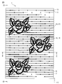
- FIG. 1 is a plan view of a nonwoven fabric 1 for wet wipes according to the first embodiment.
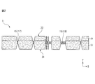
- FIG. 2 is a schematic end face view of the nonwoven fabric 1 for wet wipes at the II-II ′ end face of FIG.
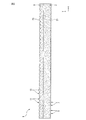
- FIG. 3 is a schematic end face view of the nonwoven fabric 1 for wet wipes at the III-III ′ end face of FIG.
- FIG. 4 is a schematic diagram of the manufacturing apparatus 49.
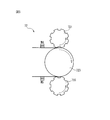
- FIG. 5 is an enlarged schematic view of the embossing machine 72 shown in FIG.
- a hydrophilic nonwoven fabric layer containing 50% by mass or more of hydrophilic fibers A hydrophobic nonwoven layer containing 50% by mass or more of hydrophobic fibers; A joint for joining the hydrophilic nonwoven fabric layer and the hydrophobic nonwoven fabric layer; With The hydrophobic fiber contains 30% by mass or more of ultrafine fibers having a fineness of 0.3 dtex or less, A nonwoven fabric for wet wipes characterized by the above.
- the wet wipes nonwoven fabric has a two-layer structure of a hydrophilic nonwoven fabric layer and a hydrophobic nonwoven fabric layer.
- the liquid impregnation rate which is the liquid impregnation rate of the hydrophilic nonwoven layer, is high, the liquid impregnation rate of the hydrophobic nonwoven layer is low, and the hydrophilic nonwoven layer and the hydrophobic nonwoven layer are joined at the joint.
- the high impregnation rate of the chemical nonwoven fabric layer and the low impregnation rate of the hydrophobic nonwoven fabric layer are easily maintained.
- a hydrophilic non-woven fabric layer with a high chemical impregnation rate is used for wiping dirt
- a hydrophobic non-woven fabric layer with a low chemical solution impregnation rate is used for finishing wiping off fine dirt remaining on the surface to be wiped. be able to. That is, since the hydrophilic nonwoven fabric layer has a high chemical solution impregnation rate when wiping dirt, it is possible to wipe off the stain efficiently.
- the hydrophobic nonwoven fabric layer has a low chemical solution impregnation rate and a surface to be wiped. Since a predetermined amount of ultrafine fibers having good slipperiness are included, the remaining dirt can be wiped off and the remaining chemical solution can be sucked up so as not to damage the surface to be wiped when finishing wiping.
- the hydrophilic nonwoven fabric layer and the bonding portion include a first heat-fusible fiber
- the hydrophobic nonwoven fabric layer and the joint include a second heat-fusible fiber
- the first heat-fusible fiber and the second heat-fusible fiber are fused in the embossed portion, so that the flexibility of each non-woven fabric layer is maintained and the non-woven fabric layer is maintained. Sufficient bonding strength can be provided.
- the joint part that joins the hydrophilic nonwoven fabric layer and the hydrophobic nonwoven fabric layer is an embossed part, there is a recess formed in the embossed part, and the surface area increases compared to the case without the embossed part, It is easy to wipe off fine dirt and can improve the wiping performance.
- Aspect 4 The nonwoven fabric for wet wipes according to any one of aspects 1 to 3, wherein the hydrophilic nonwoven fabric layer is a spunlace nonwoven fabric layer.
- the hydrophilic nonwoven fabric layer is a spunlace nonwoven fabric layer, it has a good balance between strength and flexibility to the extent that it becomes a base material for the hydrophobic nonwoven fabric layer, and has a thickness and bulkiness. Therefore, the dirt wiped off by the dirt wiping surface is difficult to transfer to the finished wiping face, and the wiping performance of the wet wipes is improved.
- Aspect 6 The wet wipe nonwoven fabric according to any one of embodiments 1 to 5, wherein the hydrophobic nonwoven fabric layer contains 30% by mass or more of ultrafine fibers having a fineness of less than 0.1 dtex. According to Aspect 6, since the hydrophobic nonwoven fabric layer contains 30% by mass or more of ultra-fine fibers of less than 0.1 dtex, which is even more slippery with the surface to be wiped, when performing wet wiping of final wipes In addition, the remaining dirt can be wiped off so as not to damage the surface to be wiped. Moreover, since the hydrophobic nonwoven fabric layer has a smooth texture, even when the chemical solution impregnation rate is low, there is little irritation to the surface to be wiped, such as skin, when finishing wiping.
- Aspect 7 The nonwoven fabric for wet wipes according to any one of aspects 1 to 6, wherein the hydrophobic nonwoven fabric layer contains 70% by mass or more of the hydrophobic fiber. According to Aspect 7, since the hydrophobic nonwoven fabric layer contains 70% by mass or more of hydrophobic fibers, it is suitable for final wiping to wipe off the chemical solution and fine dirt remaining on the surface to be wiped.
- Aspect 8 Cellulose fibers having an average fiber length of 2.5 mm to 8.0 mm and pulp fibers, the hydrophilic fibers being 30 to 90% by mass and 10 to 70% by mass, respectively, based on the mass of the hydrophilic fibers.
- the nonwoven fabric for wet wipes according to any one of aspects 1 to 7, comprising: According to Aspect 8, when the hydrophilic nonwoven fabric layer is impregnated with a chemical solution to form a wet wipe, the wet wipe strength (wet strength) can be maintained while maintaining a high chemical solution retention rate. .
- Aspect 9 Forming a hydrophilic nonwoven fabric layer containing 50% by mass or more of hydrophilic fibers; Forming a hydrophobic nonwoven fabric layer containing 50% by mass or more of hydrophobic fibers, wherein the hydrophobic fiber contains 30% by mass or more of ultrafine fibers having a fineness of 0.3 dtex or less; Forming a joint between the hydrophilic nonwoven fabric layer and the hydrophobic nonwoven fabric layer; The manufacturing method of the nonwoven fabric for wet wipes characterized by including this. According to Aspect 9, there can be obtained a unique method for producing a nonwoven fabric for wet wipes, which is the nonwoven fabric according to any one of Aspects 1 to 8, and has excellent wiping performance.
- the hydrophilic nonwoven fabric layer and the bonding portion include a first heat-fusible fiber
- the hydrophobic nonwoven fabric layer and the joint include a second heat-fusible fiber
- the method for producing a nonwoven fabric for wet wipes according to any one of Aspects 2 to 8 can be obtained, and the joining and embossing of both nonwoven layers can be simultaneously performed by hot embossing. It can be carried out.
- the hydrophilic nonwoven fabric layer is formed by forming a first web containing the hydrophilic fibers and the first heat-fusible fibers and hydroentangling the first web. 10.
- the production method according to 10. since the jet water stream is jetted onto the web and the fibers are entangled by the pressure, the balance between strength and flexibility is good, the thickness and the bulk, and the surface to be wiped It is possible to obtain a non-woven fabric suitable as wet wipes having high wiping performance, and it is possible to produce a non-woven fabric layer without using an adhesive.
- the second heat-fusible fiber has a lower melting point than the first heat-fusible fiber
- the hydrophobic non-woven fabric layer is formed on the hydrophilic non-woven fabric layer by forming a second web containing the ultrafine fiber of 0.3 dtex or less and the second heat-fusible fiber, and then the second web.
- the web is subjected to steam jet processing at a temperature higher than the melting point of the second heat-fusible fiber and lower than the melting point of the first heat-fusible fiber, and the second web of the second web.
- the steam jet processing is performed on the second web at a temperature higher than the melting point of the second heat-fusible fiber and lower than the melting point of the fiber constituting the hydrophilic nonwoven fabric layer.
- the hydrophobic nonwoven fabric layer is expanded, only the hydrophobic nonwoven fabric layer is selectively exposed to heat fusion, and the hydrophilic nonwoven fabric layer is flexible without exhibiting heat fusion properties. Can be secured. Therefore, the flexibility of the hydrophilic nonwoven fabric layer can be ensured as compared with the case where the first heat-fusible fiber and the hydrophilic fiber are fused in the hydrophilic nonwoven fabric layer.
- the steam jet processing breaks the layers that make up the steam jet collision, particularly the fibers constituting the hydrophobic nonwoven fabric layer, and the nonwoven fabric layer obtains flexibility, thickness, and bulkiness. Dirt is difficult to transfer to the surface opposite to the surface, and as a result, the wiping performance of the wet wipes is improved.
- the embossing roll is in contact with the surface on which the hydrophobic nonwoven fabric layer is present, and the anvil roll is in contact with the surface on which the hydrophilic nonwoven fabric layer is present, in the step of forming the joint portion.
- the embossing roll with unevenness has a higher thermal efficiency than the flat anvil roll by pressing the embossing roll on the surface on which the hydrophobic non-woven fabric layer on the low melting point side is present and performing heat embossing.
- the heat embossed portion of the hydrophobic nonwoven fabric layer makes it easy for the user to identify the difference between the dirt wiping surface and the finish wiping surface.
- the nonwoven fabric for wet wipes according to the present invention (hereinafter sometimes simply referred to as a nonwoven fabric) will be described in detail.
- the “first direction”, “second direction” and “thickness direction” relating to the nonwoven fabric are respectively “predetermined direction in the plane direction of the nonwoven fabric” and “predetermined direction in the plane direction of the nonwoven fabric”. “Direction perpendicular to the direction” and “thickness direction of the nonwoven fabric” are meant.
- FIG. 1 is a plan view of a nonwoven fabric 1 for wet wipes according to one of the embodiments of the present invention (first embodiment).
- FIG. 2 is a schematic end face view taken along the line II-II ′ of FIG.
- FIG. 3 is a schematic end face view of the III-III ′ end face of FIG.
- the nonwoven fabric 1 includes a hydrophilic nonwoven fabric layer 3, a hydrophobic nonwoven fabric layer 9, and a bonding portion 15.
- the hydrophilic nonwoven fabric layer 3 includes a hydrophilic fiber (not shown) and a first heat-fusible fiber (not shown), and is formed from a spunlace nonwoven fabric produced according to a manufacturing method described later.
- the hydrophobic nonwoven fabric layer 9 includes hydrophobic fibers (not shown) and second heat-fusible fibers (not shown).
- the junction part 15 has joined the hydrophilic nonwoven fabric layer 3 and the hydrophobic nonwoven fabric layer 9, and originates in the hydrophilic nonwoven fabric layer 3 in the junction part 15.
- the first heat-fusible fibers (not shown) and the second heat-fusible fibers (not shown) derived from the hydrophobic nonwoven fabric layer 9 are heat-sealed.
- the joint portion 15 includes a plurality of dot-like embossed portions 17 arranged in a staggered manner, and a linear embossed portion 19 made of a rose motif and having a linear shape having design properties.
- the hydrophilicity of the hydrophilic nonwoven fabric layer 3 and the hydrophobicity of the hydrophobic nonwoven fabric layer 9 (low hydrophilicity).
- the impregnation rate of the chemical solution in the hydrophilic nonwoven fabric layer 3 becomes higher than the impregnation rate of the chemical solution in the hydrophobic nonwoven fabric layer 9.
- the surface to be wiped is wiped with the dirt wiping surface 21 which is the surface of the wet wipes including the nonwoven fabric 1 on the hydrophilic nonwoven fabric layer 3 side
- a lot of chemical solution from the hydrophilic nonwoven fabric layer 3 is to be wiped off. Supplied to and can remove dirt.
- the hydrophilic nonwoven fabric layer 3 and the hydrophobic nonwoven fabric layer 9 are joined together by a plurality of dot-like embossed portions 17 arranged in a staggered manner. Since the non-woven fabric layer 3 and the hydrophobic non-woven fabric layer 9 are not actively joined, the chemical solution is difficult to move from the hydrophilic non-woven fabric layer 3 to the hydrophobic non-woven fabric layer 9 when removing the dirt.
- the surface to be wiped is wiped with the finish wiping surface 23 which is the surface of the hydrophobic nonwoven fabric layer 9 side of the wet wipes including the nonwoven fabric 1, the dirt that could not be removed at the time of removing the dirt becomes hydrophobic.
- the ultrafine fibers (not shown) contained in the nonwoven fabric layer 9 pick up and the chemical solution remaining on the surface to be wiped can be sucked up by the ultrafine fibers contained in the hydrophobic nonwoven fabric layer 9 using capillary action. .
- the ultra fine fibers contained in the hydrophobic nonwoven fabric layer 9 are easy to slip on the surface to be wiped, and hardly damage the surface to be wiped.
- the hydrophobic nonwoven fabric layer 9 with a low impregnation rate of the chemical solution has a small amount of the chemical solution interposed between the surface to be wiped, the hydrophobic nonwoven fabric layer 9 is wiped when it does not contain ultrafine fibers. There is a tendency to hurt the surface to be.
- the nonwoven fabric 1 has a plurality of dot-like embossed portions 17 arranged in a staggered manner, fuzzing between the dirt wiping surface 21 and the finishing wiping surface 23 of the nonwoven fabric 1 is suppressed.
- the dirt wiping surface 21 and the finish wiping surface 23 are formed with concave portions due to the dot-like embossed portions 17, and the surface areas of the dirt wiping surface 21 and the finishing wiping surface 23 are increased as compared with the case where there are no such concave portions.
- the wiping surface 21 can easily wipe off the dirt, and the wiping performance of the finishing wiping surface 23 can be improved.
- the nonwoven fabric 1 has the linear embossed part 19
- a continuous recessed part (groove part) is formed in the dirt wiping surface 21 and the finish wiping surface 23, and the dirt wiping surface 21 is compared with the case where there is no said recessed part.
- the surface area of the finish wiping surface 23 increases, the dirt wiping performance of the dirt wiping surface 21 is improved, and the finishing wiping performance of the finishing wiping surface 23 is improved.
- the nonwoven fabric 1 has the linear embossed part 19
- the nonwoven fabric 1 has aesthetics depending on the shape of the linear embossed part.
- the nonwoven fabric 1 includes a plurality of ridges 5 extending in the second direction S on the dirt wiping surface 21, which is a surface on the hydrophilic nonwoven fabric layer 3 side, and between the adjacent ridges 5.
- a plurality of groove portions 7 extending in two directions S.
- the nonwoven fabric 1 is between the some ridge part 11 extended in the 2nd direction S, and the adjacent ridge part 11 in the finish wiping surface 23 which is the surface by the side of the hydrophobic nonwoven fabric layer 9.
- FIG. And a plurality of grooves 13 extending in the second direction S.
- the fine fiber (not shown) contained in the hydrophobic nonwoven fabric layer 9 picks up and the chemical solution remaining on the surface to be wiped is easily absorbed by the ultrafine fiber contained in the hydrophobic nonwoven fabric layer 9 by utilizing the capillary phenomenon.
- the some collar part 11 and the some groove part 13 can be formed by the below-mentioned high pressure steam processing method etc.
- the hydrophilic nonwoven fabric layer contains 50% by mass or more of hydrophilic fibers based on the mass of the hydrophilic nonwoven fabric layer.
- the hydrophilic fiber means a fiber having an official moisture content defined by JIS L 0105: 2006 “General rules of physical test methods for textile products” 4.1 in the range of 8.5 to 15.0 mass%. If the official moisture content of the hydrophilic fiber is higher than this range, the hydrophilicity becomes too high and it becomes difficult to separate the chemical solution, and there is a possibility that the chemical solution is difficult to ooze when used as wet wipes.
- the hydrophilic fiber preferably contains a fiber having an official moisture content in the range of 8.5 to 12.0% by mass.
- the hydrophilic fiber is not particularly limited as long as it has the above-mentioned official moisture content.
- cellulose fiber pulp fiber, natural fiber such as cotton, regenerated cellulose such as rayon and cupra, semisynthetic cellulose Etc.
- the hydrophilic nonwoven fabric layer preferably contains the hydrophilic fiber in an amount of 70% by mass or more, more preferably 80 to 95% by mass, and still more preferably 85% based on the mass of the hydrophilic nonwoven fabric layer. Contains ⁇ 92% by mass.
- the hydrophilic nonwoven fabric layer contains the hydrophilic fiber in the above range, the hydrophilic nonwoven fabric is excellent in absorbency and water retention when used as wet wipes.
- the hydrophilic fiber preferably includes a fiber having a long fiber length as a skeleton of the hydrophilic nonwoven fabric layer, and the fiber having a long fiber length is preferably 2.5 mm to 8.0 mm, and more preferably 3.0 mm. Having an average fiber length of ⁇ 7.0 mm.
- the fiber having a long fiber length include the cellulose-based fibers described above.
- the said fiber with a long fiber length does not contain a pulp fiber.
- “average fiber length” other than pulp fiber is “A7.1.1 A method (standard method)” in “A7.1 Measurement of fiber length” in Annex A of JIS L 1015: 2010. It means the average fiber length measured according to “Method of measuring the length of individual fibers on a graduated glass plate”.
- the hydrophilic fiber preferably contains a fiber having a shorter fiber length than a fiber having a longer fiber length in order to improve the water absorption and water retention of the hydrophilic nonwoven fabric layer.
- the fibers having a short fiber length preferably have an average fiber length of 2.0 to 3.0 mm.
- a pulp fiber is preferable.
- the average fiber length of the above-mentioned pulp fibers means a weight-weighted average fiber length, and is measured by Kajaani Fiber Lab Fiber Properties (offline) [kajaani Fiber Lab properties (off-line)] manufactured by Metso Automation. L (w) value.
- the hydrophilic fiber is preferably a fiber having a long fiber length and a fiber having a short fiber length, preferably from 30 to 30 on the basis of the mass of the hydrophilic fiber. 90% by weight and 10 to 70% by weight, more preferably 40 to 85% by weight and 15 to 60% by weight, and still more preferably 50 to 80% by weight and 20 to 50% by weight.
- the hydrophilic nonwoven fabric layer is impregnated with a chemical solution to form a wet wipe, the strength (wet strength) of the wet wipe can be maintained while maintaining a high chemical solution retention rate.
- the fineness of the hydrophilic fibers is preferably more than 0.1 dtex and 1.2 dtex or less, more preferably more than 0.3 dtex and 1.0 dtex or less, excluding pulp fibers. It is. When the fineness of the hydrophilic fiber is in this range, the strength of the entire nonwoven fabric for wet wipes can be ensured while having soft characteristics and texture.
- the hydrophilic nonwoven fabric layer may further include a first heat-fusible fiber.
- the first heat fusible fiber preferably has a melting point in the range of 130 ° C. to 160 ° C., and more preferably 135 ° C. to 150 ° C. This is because when the manufacturing method described later is performed, if the melting point of the first heat-fusible fiber is within this range, it is difficult to impair the flexibility of the hydrophilic nonwoven fabric layer or the entire nonwoven fabric for wet wipes.
- the type of the first heat-fusible fiber is not particularly limited as long as the melting point is in the above range.
- polyolefin fibers such as polyethylene (PE) fibers and polypropylene (PP) fibers
- polyester fibers And polyamide fibers such as nylon.
- first heat-fusible fiber and the second heat-fusible fiber described later may be a composite fiber including a high melting point component and a low melting point component, for example, a core-sheath type composite fiber. preferable. It is from a viewpoint which suppresses that a melt
- the first heat-fusible fiber or the second heat-fusible fiber described later is a composite fiber containing a high melting point component and a low melting point component
- the above-mentioned melting point is a low melting point. It means the melting point of the component.
- the hydrophilic nonwoven fabric layer when the hydrophilic nonwoven fabric layer includes hydrophilic fibers and first heat-fusible fibers, the hydrophilic nonwoven fabric layer comprises hydrophilic fibers and first heat-fusible fibers.
- the hydrophilic fiber and the first heat-fusible fiber are preferably 50% by mass or more and less than 100% by mass and more than 0% by mass and 50% by mass or less, more preferably 50 to 50% by mass, respectively. 99% by weight and 1-50% by weight, more preferably 70-99% by weight and 1-30% by weight, even more preferably 80-95% by weight and 5-20% by weight, and even more preferably 85-92% In a range of 8% by mass to 15% by mass.
- flexibility of a hydrophilic nonwoven fabric layer can be made compatible so that it may mention later.
- the hydrophilic nonwoven fabric layer when the hydrophilic nonwoven fabric layer includes a hydrophilic fiber and a first heat-fusible fiber, the first heat-fusible fiber is other than the first heat-fusible fiber. It is preferable that the fiber is not fused with, for example, a hydrophilic fiber. By doing so, the softness
- the hydrophilic nonwoven fabric layer may contain first additional fibers other than the hydrophilic fiber and the first heat-fusible fiber within the range where the effects of the present invention are exhibited.
- the first additional fiber may have the above-mentioned official moisture content of less than 8.5% by weight or greater than 15.0% by weight.
- the first additional fiber can also have a melting point greater than 160 ° C. Examples of the first additional fiber include a hydrophobic fiber described later.
- the hydrophilic nonwoven fabric layer when the hydrophilic nonwoven fabric layer includes the first additional fiber, the hydrophilic nonwoven fabric layer includes the first additional fiber, the hydrophilic fiber, and the optional first heat fusion. It is preferably contained in a range of 20% by mass or less, more preferably 10% by mass or less, and further preferably 5% by mass or less, based on the total mass of the adhesive fibers.
- the hydrophilic nonwoven fabric layer was the spunlace nonwoven fabric layer
- a hydrophilic nonwoven fabric layer can be arbitrary nonwoven fabrics, for example, an air through nonwoven fabric.
- the hydrophilic nonwoven fabric layer is preferably a spunlace nonwoven fabric layer.
- the spunlace nonwoven fabric layer has a good balance between strength and flexibility necessary to become the base material of the hydrophobic nonwoven fabric layer described later, and has a thickness and bulkiness, so that the dirt wiped off by the dirt wiping surface is finished. There is an advantage that it is difficult to shift to the surface and the wiping performance of wet wipes is improved.
- the hydrophilic nonwoven layer preferably has a basis weight of 10 to 60 g / m 2 , more preferably 20 to 50 g / m 2 , and even more preferably 25 to 40 g / m 2 .
- the hydrophilic nonwoven fabric layer can be sufficiently impregnated with the chemical solution, and the rigidity of the hydrophilic nonwoven fabric layer can be increased, and the wiping performance on the surface to be wiped can be prevented from being lowered.
- the basic weight of a nonwoven fabric, a hydrophilic nonwoven fabric layer, and the below-mentioned hydrophobic nonwoven fabric layer is measured as follows.
- sample pieces (10 mm ⁇ 10 mm) are cut out from the nonwoven fabric.
- a sample piece is prepared avoiding the joint portion if possible.
- One sample piece may be divided into a plurality of pieces.
- an adhesive such as hot melt, cold spraying is appropriately performed. Is used to peel off the hydrophilic nonwoven fabric layer and the hydrophobic nonwoven fabric layer.
- the mass of the sample piece was measured with a direct balance (for example, electronic balance HF-300 manufactured by Kensei Kogyo Co., Ltd.), and the mass per unit area of the sample piece calculated from the average value of the mass of the sample piece for three times ( g / m 2 ) is the basis weight of the hydrophilic nonwoven fabric layer, the hydrophobic nonwoven fabric layer and the nonwoven fabric.
- a direct balance for example, electronic balance HF-300 manufactured by Kensei Kogyo Co., Ltd.
- the hydrophilic nonwoven fabric layer preferably has a plurality of ridges and a plurality of grooves on the dirt removing surface. This is from the viewpoint of removing dirt.
- a hydrophobic nonwoven fabric layer contains 50 mass% or more of hydrophobic fibers.
- the hydrophobic fiber has the above-mentioned official moisture content in the range of 0.4 to 7.0% by mass. If the official moisture content of the hydrophobic fiber is higher than this range, the hydrophilicity becomes stronger and it becomes easier to retain the chemical when impregnated with the chemical, and it is wiped when used as a wet wipe for finishing wiping. There is a possibility that the performance of wiping off chemicals and dirt remaining on the surface to be inferior is inferior.
- the hydrophobic fiber preferably includes a fiber having an official moisture content of 0.4 to 4.5% by mass from the viewpoint of the effect of the present invention.
- hydrophobic fibers those used as hydrophobic fibers in the art can be used without particular limitation as long as they have the above-mentioned official moisture content.
- nylon-6, nylon-66, etc. Polyamides such as nylon fibers, recycled fibers such as acetate, polyethylene terephthalate (PET), acrylic, polyester, Promix (registered trademark), and the like.
- the hydrophobic nonwoven fabric layer contains the hydrophobic fiber, preferably 70% by mass or more, and more preferably 80% by mass or more. This is to ensure the hydrophobicity of the hydrophobic nonwoven fabric layer.
- the hydrophobic nonwoven fabric layer may include fibers other than the hydrophobic fibers (hereinafter referred to as “non-hydrophobic fibers”).
- Non-hydrophobic fibers have an official moisture content of less than 0.4% by weight or greater than 7.0% by weight.
- non-hydrophobic fibers include water-repellent fibers such as polyethylene-based synthetic fibers and the above-described hydrophilic fibers.
- the hydrophobic nonwoven fabric layer when the hydrophobic nonwoven fabric layer includes non-hydrophobic fibers, the hydrophobic nonwoven fabric layer includes the hydrophobic fibers and the non-hydrophobic fibers, respectively, and the mass of the hydrophobic nonwoven fabric layer.
- it is preferably 50% by mass or more and less than 100% by mass and more than 0% by mass and 50% by mass or less, more preferably 50 to 99% by mass and 1 to 50% by mass, and further preferably 70 to 99% by mass and 1%. Up to 30% by weight, and even more preferably in the range of 75-95% by weight and 5-25% by weight.
- the hydrophobic fiber preferably has a fineness of 3.0 dtex, more preferably 2.0 dtex, and even more preferably 1.5 dtex or less.
- the hydrophobic fiber is an ultrafine fiber having a fineness of 0.3 dtex or less, based on the mass of the hydrophobic fiber, 30 mass% or more, preferably 40 mass%, more preferably Contains 50% by weight and more preferably 60% by weight or more.
- the hydrophobic nonwoven fabric layer includes a predetermined amount of ultrafine fibers. Therefore, even if the impregnation rate of the chemical solution is low, the hydrophobic nonwoven fabric layer is between the fibers constituting the hydrophobic nonwoven fabric layer and the surface to be wiped. The surface to be wiped is hard to be damaged when finishing wiping. Moreover, the said nonwoven fabric can hold
- a fiber having a fineness exceeding 0.3 dtex may be referred to as a “non-fine fiber”.
- the hydrophobic fiber may include ultrafine fibers having a fineness of 0.1 dtex or less.
- the surface to be wiped is hard to be damaged when performing the finish wiping using the wet wipes.
- the hydrophobic nonwoven fabric layer has a smooth texture, even when the chemical solution impregnation rate is low, there is little irritation to the surface to be wiped, such as skin, when finishing wiping.
- the said super extra fine fiber is contained in the range of the above-mentioned extra fine fiber.
- the hydrophobic fibers preferably have an average fiber length in the range of 2.5 mm to 8.0 mm, and more preferably 3.0 mm to 7.0 mm. This is from the viewpoint of the strength of the nonwoven fabric, particularly the wet strength when the nonwoven fabric is impregnated with a chemical solution to form wet wipes.
- the hydrophobic nonwoven fabric layer may include heat-bonded fibers (hereinafter sometimes referred to as “second heat-bondable fibers”), and the hydrophobic nonwoven fabric layer. Is formed by heating a web containing hydrophobic fibers containing ultrafine fibers and second heat-fusible fibers, and heat-sealing the second heat-fusible fibers, that is, It is preferable that the second heat-fusible fibers are heat-sealed. By doing so, the fine fibers contained in the hydrophobic nonwoven fabric layer can easily work to prevent the surface to be wiped from being damaged when performing final wiping with wet wipes.
- the hydrophobic nonwoven fabric layer may include fibers that are not thermally fused (hereinafter, may be referred to as “second non-thermally fusible fibers”).
- the second heat-fusible fiber defines and identifies the fiber contained in the hydrophobic nonwoven fabric layer from the viewpoint of the melting point, and the fiber contained in the hydrophobic nonwoven fabric layer identifies the fiber contained in the hydrophobic nonwoven fabric layer from the viewpoints of hydrophobicity and hydrophilicity. It is a different concept from the “hydrophobic fiber” and any “non-hydrophobic fiber” that are defined and specified from the above. Therefore, the above-mentioned second heat-fusible fiber may be partitioned into “hydrophobic fiber” or arbitrary “non-hydrophobic fiber” from the viewpoint of hydrophobicity and hydrophilicity. The second heat-fusible fiber is generally divided into the above-described hydrophobic fibers.
- the second heat-fusible fiber includes a “non-fine fiber” and an “ultra-fine fiber” that specify and identify the fibers contained in the hydrophobic nonwoven fabric layer from the viewpoint of fineness.
- the second heat-fusible fiber may be divided into the above-mentioned non-ultrafine fiber, ultrafine fiber, or ultrafine fiber from the viewpoint of fineness, but from the viewpoint of the strength of the hydrophobic nonwoven fabric layer,
- the heat-fusible fiber 2 is preferably partitioned into non-fine fibers (having a fineness of 0.3 dtex or more) from the viewpoint of fineness.
- the second heat-fusible fiber preferably has a melting point in the range of 90 ° C. to 130 ° C., and more preferably 100 ° C. to 120 ° C. This is because if the melting point of the hydrophobic fiber is within this range when the production method described later is carried out, it is difficult to impair the flexibility of both the hydrophobic nonwoven fabric layer and the hydrophilic nonwoven fabric layer.
- the second non-heat-fusible fiber has a higher melting point than the second heat-fusible fiber, preferably more than 160 ° C, more preferably 170 ° C or more, and even more preferably 180 ° C or more. Has a melting point. By doing so, the difference in melting point between the second non-heat-fusible fiber and the second heat-fusible fiber is increased, and the second heat-fusible fiber is fused during production. Thus, the adjustment not to fuse the second non-heat-fusible fiber is simplified.
- the hydrophobic nonwoven fabric layer of the nonwoven fabric of the present invention contains the second heat-fusible fiber
- the hydrophobic nonwoven fabric layer contains the second heat-fusible fiber and the second non-heat-fusible fiber.
- a hydrophobic nonwoven fabric layer is excellent in the strength, especially the wet strength when used as wet wipes.
- the second heat-fusible fiber examples include polyolefin fibers such as polyethylene (PE) fibers and polypropylene (PP) fibers, polyester fibers, and polyamide fibers such as nylon.
- the finishing wiping surface on the hydrophobic nonwoven fabric layer side has a plurality of ridges and a plurality of grooves arranged between adjacent ridges.
- the plurality of flanges and the plurality of grooves may extend in a predetermined direction.
- the hydrophobic nonwoven layer preferably has a basis weight in the range of 5 to 50 g / m 2 , more preferably 10 to 40 g / m 2 , and even more preferably 15 to 30 g / m 2 .
- the hydrophobic nonwoven fabric layer has a certain thickness so that it can be easily wiped with finish, and the hydrophobic nonwoven fabric layer has a high rigidity and suppresses a decrease in wiping performance on the surface to be wiped. be able to.
- junction part In the nonwoven fabric of this invention, a junction part will not be restrict
- the bonding portion may be an embossed portion as shown in the first embodiment, and by adhering the hydrophilic nonwoven fabric layer and the hydrophobic nonwoven fabric layer entirely or partially with an adhesive. It can also be an adhesive part formed and is preferably an embossed part. This is because the embossed portion acts to increase the surface area of the dirt removal surface and the finish wiping surface.
- the joint portion may be disposed on the entire surface of the nonwoven fabric, and may be disposed in a linear shape, a dot shape, or the like.
- nonwoven fabric for wet wipes Since the nonwoven fabric for wet wipes according to the present invention has a two-layer structure of a hydrophilic nonwoven fabric layer and a hydrophobic nonwoven fabric layer, the wet nonwoven fabric obtained by impregnating the wet wipes nonwoven fabric with a chemical solution is a hydrophilic nonwoven fabric.
- the chemical liquid impregnation rate of the layer is high, the chemical liquid impregnation rate of the hydrophobic nonwoven fabric layer is low, and the hydrophilic nonwoven fabric layer and the hydrophobic nonwoven fabric layer are joined at the joint. It is easy to maintain the height and the low chemical impregnation rate of the hydrophobic nonwoven fabric layer.
- a hydrophilic non-woven fabric layer with a high chemical impregnation rate is used for wiping dirt
- a hydrophobic non-woven fabric layer with a low chemical solution impregnation rate is used for finishing wiping to wipe off fine dirt remaining on the surface to be wiped.
- the hydrophilic nonwoven fabric layer has a high chemical solution impregnation rate (ie, a large amount of chemical solution) when wiping the stain, so that the stain can be efficiently wiped off.
- the hydrophobic nonwoven fabric layer has a low chemical solution impregnation rate.
- the surface to be wiped contains a predetermined amount of ultrafine fibers that have good slidability with the surface to be wiped, so when finishing wiping, wipe off the remaining dirt and suck up the remaining chemical solution so as not to damage the surface to be wiped be able to.
- the nonwoven fabric of the present invention preferably has a basis weight of 20 to 100 g / m 2 , more preferably 30 to 80 g / m 2 , and still more preferably 40 to 60 g / m 2 .
- the nonwoven fabric of this invention has the said basic weight, the dirt which the dirt wiping surface wiped off becomes difficult to transfer to a finishing wiping surface, and a user is easy to learn a sense of security at the time of use of wet wipes.
- the nonwoven fabric of the present invention preferably has a wet thickness of 0.35 to 0.80 mm, more preferably 0.40 to 0.70 mm. By doing so, the dirt wiped off by the dirt wiping surface becomes difficult to transfer to the finished wiping surface, and the user can easily feel a sense of security when using the wet wipes.
- the wet thickness is measured as follows.
- a non-woven fabric is impregnated with ion-exchanged water in an amount of 250% by mass (impregnation rate) with respect to the mass of the non-woven fabric, and a thickness gauge (model FS- manufactured by Daiei Scientific Instruments Co., Ltd.) equipped with a 15 cm 2 measuring element 60DS), and the thickness of the nonwoven fabric is measured under the measurement condition of the measurement load of 3 gf / cm 2 .
- Three thicknesses are measured for one measurement sample, and the average value of the three thicknesses is defined as the wet thickness.
- a nonwoven fabric contains a chemical
- natural drying or ion-exchange water is added, and an impregnation rate is adjusted to 250 mass%.
- the nonwoven fabric for wet wipes of this invention impregnates a chemical
- the chemical liquid include those used in the art as chemical liquids for wet wipes without particular limitation, and examples thereof include an aqueous solution containing an antibacterial agent, a surfactant, a preservative, and the like.
- the chemical solution may be distilled water.
- the impregnation ratio of the chemical solution in the wet wipes, that is, the mass ratio of the chemical solution to the nonwoven fabric for wet wipes is not particularly limited, and examples thereof include 100 to 500%.
- the surface to be wiped by the nonwoven fabric for wet wipes of the present invention is not particularly limited, but is preferably a surface that is easily damaged.
- the surface to be wiped includes soft surfaces such as animal skin, such as human skin, hard surfaces, hard and glossy article surfaces, mirrors, glasses, eyeglass lenses, and the like, and preferably Examples include human skin, more preferably baby skin with weak skin.
- FIG. 4 is a schematic diagram of a manufacturing apparatus 49 for carrying out the method for manufacturing a nonwoven fabric according to one of the embodiments of the present invention (second embodiment).
- a mixture of fibers (hydrophilic fibers, first heat-fusible fibers) constituting the hydrophilic nonwoven fabric layer and water is prepared.
- the mixture of fibers and water is supplied onto the support 54 of the web forming conveyor 52 by the hydrophilic nonwoven layer raw material supply head 50 and is deposited on the support 54.
- the support preferably has air permeability through which water vapor can pass.
- a wire mesh or a blanket can be used for the support.
- the fiber containing water deposited on the support is disposed at a position opposite to the two high-pressure water flow nozzles 55 disposed on the support 54 and the high-pressure water flow nozzle 55 with the support interposed therebetween.
- the sheet W1 passes through a suction box 57 that collects the collected water.
- the fibers containing water strengthen the strength of the sheet W1 by interlacing the fibers, and even if high-pressure steam is sprayed on the sheet W1 in a later step, a hole is opened. Less torn, torn, and blown away. Further, the wet strength of the sheet W1 can be increased without adding a paper strength enhancer to the nonwoven fabric raw material.
- the energy amount of the high-pressure water stream is preferably 0.125 to 1.324 kW / m 2 .
- the amount of energy in the water stream: E (kW / m 2 ) is calculated from the following equation.
- E (kW / m 2 ) 1.63 x injection pressure (Kg / cm 2 ) x injection flow rate (m 3 / min) / processing speed (m / min) / 60 here,
- Injection flow rate (m 3 / min) 750 x orifice orifice total area (m 2 ) x injection pressure (Kg / cm 2 ) ⁇ 0.495
- the energy amount of the water flow is too small, the strength of the sheet W1 may not be so strong. On the contrary, if the energy amount of the water flow is too large, the sheet W1 becomes too hard, and the volume of the sheet W1 may not be so high due to the high-pressure steam described later.
- the hole diameter of the high-pressure water flow nozzle is preferably 90 to 150 ⁇ m.
- the hole diameter of the high-pressure water nozzle 55 is 90 ⁇ m or more, the problem that the nozzle is likely to be clogged hardly occurs. Further, when the hole diameter of the high-pressure water flow nozzle is 150 ⁇ m or less, the problem that the processing efficiency deteriorates hardly occurs.
- the hole pitch (distance between the centers of adjacent holes) of the high-pressure water nozzle is preferably 0.3 to 1.0 mm.
- the hole pitch of the high-pressure water nozzle 55 is 0.3 mm or more, the pressure resistance of the nozzle is reduced and the problem of breakage is unlikely to occur. Further, when the hole pitch of the high-pressure water flow nozzle 55 is 1.0 mm or less, the problem that the fiber entanglement becomes insufficient hardly occurs.
- the hydrophilic nonwoven fabric layer is formed by the hydroentanglement method described above.
- the hydrophilic nonwoven fabric layer may be formed by other methods.
- the high-pressure water flow nozzle 55 injects a high-pressure water flow onto the sheet W1 at substantially equal intervals in the first direction F (hereinafter also referred to as CD direction) of the sheet W1.
- CD direction first direction
- the surface of the sheet W1 on which the high-pressure water flow is jetted extends substantially linearly in the second direction S (hereinafter also referred to as MD direction) at substantially equal intervals in the first direction F.
- MD direction second direction
- a groove portion and a flange portion extending in the second direction adjacent to the groove portion are formed in the first direction. This groove structure corresponds to the groove portion 7 and the flange portion 5 described with reference to FIG.
- the sheet W1 passes over the hydrophobic nonwoven fabric raw material head 59.
- fibers constituting the hydrophobic nonwoven fabric layer (hydrophobic fibers, second heat-fusible fibers) are adjusted.
- the fibers constituting the hydrophobic nonwoven fabric layer move from the mesh drum onto the sheet W1 to form the web W2.
- a laminate in which the web W2 is laminated on the sheet W1 is referred to as an intermediate W3.
- the intermediate W ⁇ b> 3 is transferred to the paper layer transport conveyor 61 and transferred to the first Yankee dryer 63.
- the Yankee dryer 63 attaches the intermediate body W3 to the drum heated to about 110 ° C. with water vapor, and dries the intermediate body W3.
- the moisture content of the intermediate W3 is preferably 10 to 45% by mass by drying with the first dryer.
- a moisture content is the percentage of the gram number of the water contained with respect to the total mass 100g of the web containing water. If the water content of the intermediate W3 is too small, the hydrogen bonding force between the fibers of the intermediate W3 becomes strong, and the energy required for unraveling the fibers of the intermediate W3 with water vapor described later becomes very high. On the other hand, if the water content of the intermediate W3 is too large, the energy required for drying the intermediate W3 to a predetermined water content or less by water vapor described later becomes very high.
- the intermediate body W3 moves onto the mesh-shaped outer peripheral surface of the cylindrical suction drum 65.
- a surface where the high-pressure steam is present from the high-pressure steam nozzle 67 disposed above the outer peripheral surface of the suction drum 65 with respect to the intermediate W3 (hereinafter referred to as high-pressure steam treatment (SJ)). Sprayed so as to collide with the surface.
- SJ high-pressure steam treatment
- FIG. 4 two rows of high-pressure steam nozzles 67 are arranged, but the number of high-pressure steam nozzles may be one, or three or more.
- the suction drum 65 has a built-in suction device, and the steam blown from the high-pressure steam nozzle 67 is sucked by the suction device. By the steam sprayed from the high-pressure steam nozzle 67, a ridge groove structure is formed on the high-pressure steam-treated surface of the intermediate W3.
- the pressure of water vapor sprayed from the high-pressure steam nozzle is preferably 0.3 to 1.5 MPa, more preferably 0.4 to 1.2 MPa, and even more preferably 0.5 to 1.0 MPa. is there. If the water vapor spraying pressure is too small, the fiber blowing effect is weak and it becomes difficult to form the buttock. Conversely, if it is too large, the damage to the sheet becomes too large and the strength tends to decrease.
- the water vapor blown from the high-pressure water vapor nozzle 67 may be a mixture of other gases such as air, but is preferably composed only of water vapor.
- the high-pressure steam nozzle 67 disposed above the suction drum 65 sprays high-pressure steam on the intermediate body W3 at substantially equal intervals in the first direction F (CD direction) of the intermediate body W3.
- a groove portion extending substantially linearly in the second direction S (MD direction) at substantially equal intervals in the first direction S is formed adjacent to the groove portion.
- This ridge groove structure corresponds to the ridge portion 11 and the groove portion 13 described with reference to FIG.
- the groove structure is imparted to the web W2 constituting the hydrophobic nonwoven fabric layer, and the surface area of the hydrophobic nonwoven fabric layer is increased, so that fine dirt can be easily wiped off and the wiping performance can be improved.
- the fibers of the intermediate W3 (in particular, the web W2) are unwound and the bulk of the web W2 increases.
- the intermediate body W3 that has been hardened by the pressure and water flow at the time of transfer has increased flexibility, and the tactile sensation of the intermediate body W3 is improved.
- the suction force by which the suction drum 65 sucks the intermediate W3 by the suction device built in the suction drum 65 that sucks the steam blown from the high-pressure steam nozzle 67 is preferably ⁇ 1 to ⁇ 12 kPa.
- the suction force of the suction drum 65 is ⁇ 1 kPa or more, it is difficult to cause a problem that water vapor cannot be sucked up and blown up, which is dangerous.
- the suction force of the suction drum 65 is ⁇ 12 kPa or less, the problem that the fibers fall into the suction is less likely to occur.
- the distance between the tip of the high-pressure steam nozzle and the upper surface of the web W2 is preferably 1.0 to 10 mm. If the distance between the tip of the high-pressure steam nozzle and the upper surface of the web W2 is smaller than 1.0 mm, there may be a problem that a hole is formed in the web W2, the web W2 is torn or blown off. If the distance between the tip of the high-pressure steam nozzle and the upper surface of the web W2 is greater than 10 mm, the force for forming grooves on the surface of the web W2 in the high-pressure steam is dispersed, and the surface of the web W2 is dispersed. The efficiency of forming the groove is deteriorated.
- the hole diameter of the high pressure steam nozzle is preferably larger than that of the high pressure water nozzle, and the hole pitch of the high pressure steam nozzle is preferably larger than the hole pitch of the high pressure water nozzle.
- the hole diameter of the high pressure steam nozzle is preferably 150 to 600 ⁇ m. If the hole diameter of the water vapor nozzle is too small, there may be a problem that the energy is insufficient and the fibers cannot be scraped sufficiently. Further, if the hole diameter of the high-pressure steam nozzle is too large, there may be a problem that the energy is too large and the substrate damage becomes too large.
- the hole pitch of the high-pressure steam nozzle (distance between the centers of adjacent holes) is preferably 1.0 to 3.0 mm. If the hole pitch of the high-pressure steam nozzle is too small, the pressure resistance of the nozzle may be reduced, which may cause a problem of breakage. Further, if the hole pitch of the high-pressure steam nozzle is too large, there may be a problem that the fibers cannot be scraped sufficiently.
- the temperature of the high-pressure steam needs to be higher than the melting point of the second heat-fusible fiber and lower than the melting point of the first heat-fusible fiber, preferably 110 to 140 ° C., and more preferably 120 to 130 ° C.
- the laminated body (intermediate body W3) of the hydrophilic nonwoven fabric layer and the hydrophobic nonwoven fabric layer-forming web is higher than the melting point of the second heat-fusible fiber and the fibers constituting the hydrophilic nonwoven fabric layer.
- the flexibility of the hydrophilic nonwoven fabric layer can be ensured as compared with the case where the first heat-fusible fiber and the hydrophilic fiber are fused in the hydrophilic nonwoven fabric layer.
- the high-pressure steam processing allows the high-pressure steam to collide, particularly the fibers constituting the hydrophobic nonwoven fabric layer, and the layer obtains flexibility, thickness, and bulkiness. As a result, it is difficult for dirt to migrate to the opposite surface, and as a result, the wiping performance of wet wipes is improved.
- the moisture content of the intermediate W3 after spraying high-pressure steam is preferably 45% by mass or less, and more preferably 40% by mass or less. If the moisture content of the intermediate W3 after wiping high-pressure steam is greater than 45% by mass, the moisture content of the intermediate W3 may not be reduced to 5% by mass or less by drying with a second Yankee dryer described later. is there. In this case, additional drying is required, and the production efficiency of the nonwoven fabric is deteriorated.
- the intermediate W ⁇ b> 3 is transferred to the second Yankee dryer 69.
- the second Yankee dryer 69 attaches the intermediate W3 to the drum heated to about 125 ° C. with water vapor, and dries the intermediate W3.
- the intermediate W3 after passing through the second Yankee dryer needs to be sufficiently dry.
- the moisture content of the sheet W4 after passing through the second Yankee dryer is 5% by mass or less.
- the dried sheet W4 passes through an embossing machine 72 described later, and is wound around the winder 74 as a nonwoven fabric W5.
- FIG. 5 is an enlarged schematic view of the embossing machine 72 shown in FIG.
- the sheet W4 is subjected to an embossing process by an embossing machine 72 shown in FIG.
- the sheet W4 is set on the embossing machine 72 so that the web W2 side (high-pressure steam-treated surface) of the sheet W4 becomes the embossed surface, and the first heat-fusible property is formed by the first embossing roll 721 and the anvil roll 723 in both the upper and lower sides.
- a point-like embossing treatment is performed on the entire surface of the high-pressure steam-treated surface of the sheet W4 at a temperature equal to or higher than the melting point of the fiber (for example, a temperature of 135 ° C.).
- the first embossing roll 721 is arranged so that the polka dot concave pattern is 5 mm apart in the circumferential direction, 5 mm apart in the width direction, 1.3 mm pattern depth, and the convex area ratio is 14.4%.
- the arrangement of the first embossing roll is not limited to the above, but this arrangement has a convex area ratio of preferably 8% to 20%, more preferably 10% to 15%. This is because when the convex area ratio is in this range, the bonding strength between the sheets W1 and W2 by embossing is ensured and the flexibility between the sheets W1 and W2 is easily maintained.
- the first embossing roll 721 causes the sheet W4 to be too hard to be heated by performing the embossing process in a dot shape at a temperature at which the heat-fusible fiber contained in the sheet W1 (hydrophilic nonwoven layer) can be melted.
- the hydrophilic nonwoven fabric layer and the hydrophobic nonwoven fabric layer can be heat-sealed so as not to peel off.
- fluffing at the time of use can be prevented by locally pressing a large number of fibers of the hydrophobic nonwoven fabric layer and thermally fusing them.
- the high-pressure steam-treated surface of the sheet W4 that has been subjected to the point-like embossing treatment is further above the melting point of the first heat-fusible fiber (for example, 135 ° C.) by the second embossing roll 725 and the anvil roll 723.
- the design embossing process is partially performed on the high-pressure steam-treated surface of the sheet W4.
- the second embossing rolls 725 are arranged such that the rose floral pattern is spaced 135 mm in the circumferential direction, spaced 93 mm in the width direction, and patterned depth 0.67 to 0.75 mm.
- the second embossing roll 725 can partially form a pattern that improves the design and wiping properties, enhances the aesthetics, and can impart the effect of scraping off dirt with a large uneven pattern.
- the embossing roll with unevenness is less heat efficient than the flat anvil roll. It is difficult for heat to be transmitted to parts other than the heat embossed part of the porous nonwoven fabric layer, the second heat-fusible fiber can be prevented from being melted again and the nonwoven fabric layer becomes hard, and the thickness of the nonwoven fabric layer is secured.
- the nonwoven fabric suitable as wet wipes with high wiping performance can be obtained. Further, the heat embossed portion of the hydrophobic nonwoven fabric layer makes it easy for the user to identify the difference between the dirt wiping surface and the finish wiping surface.
- the nonwoven fabric for wet wipes which concerns on this invention can be produced.
- the said manufacturing method is an example of the manufacturing method of the nonwoven fabric for wet wipes which concerns on this invention, and the manufacturing method of the nonwoven fabric for wet wipes which concerns on this invention is not limited above.
- the arrangement pattern of the first and second embossing rolls can be appropriately changed as long as the effects obtained by the respective embossing processes can be exhibited.
- wet wipes are obtained by impregnating the manufactured nonwoven fabric with a liquid.
- the method for impregnating the liquid is not particularly limited, and examples thereof include spray impregnation and immersion impregnation.
- Example 1 Using a manufacturing apparatus as shown in FIGS. 4 and 5, a nonwoven fabric for wet wipes was produced as follows. First, rayon with softwood bleached kraft pulp (NBKP) (Canadian Freeness Standard (cfs) 700 cc) (official moisture content 12.0 mass%) 30 mass%, fineness 0.7 dtex, and average fiber length 7 mm (Corona manufactured by Daiwabo Rayon Co., Ltd.) (official moisture content 11.0% by mass) 60% by mass and SWP (E400) having a melting point of 135 ° C. (polyethylene fiber manufactured by Mitsui Chemicals) (official moisture content 0.0 (Mass%) The hydrophilic nonwoven fabric raw material containing 10 mass% was prepared.
- a hydrophilic non-woven fabric layer raw material was supplied onto a web forming conveyor support (OS 80 manufactured by Nippon Filcon Co., Ltd.) so that the basis weight was 30 g / m 2 .
- the sheet W1 was obtained by dehydrating with a suction box while spraying high pressure water flow using two high pressure water flow nozzles.
- the hole diameter of the high-pressure water nozzle is 92 ⁇ m
- the hole pitch of the high-pressure water nozzle is 0.5 mm
- the energy amount of the high-pressure water stream sprayed on the web using two high-pressure water nozzles is 0.325 kW / m 2 ( 0.163 kW / m 2 ⁇ 2)
- the traveling speed of the sheet W1 was 80 m / min.
- PET fiber (TA04PN manufactured by Teijin Ltd.) (official moisture content 0.4 mass%) 50 mass% with fineness of 0.06 dtex and average fiber length of 6 mm, fineness of 1.1 dtex, low
- the hydrophobic nonwoven fabric layer raw material was supplied onto the sheet W1 so that the basis weight was 20 g / m 2 , thereby obtaining an intermediate W3 in which the web W2 was laminated on the sheet W1.
- the intermediate W3 was transferred to a paper layer conveyor, and then transferred to a Yankee dryer heated to 110 ° C. and dried.
- high-pressure steam was sprayed on the surface of the intermediate W3 where the web W2 exists using two steam nozzles.
- the pressure of the high-pressure steam at this time is 0.4 MPa
- the temperature is about 140 ° C.
- the distance between the tip of the steam nozzle and the upper surface of the web is 2.0 mm
- the pore diameter of the steam nozzle is 300 ⁇ m.
- the hole pitch was 2.0 mm
- the traveling speed of the intermediate W3 was 80 m / min.
- a stainless steel 18 mesh perforated sleeve was used on the outer periphery of the suction drum. Then, the intermediate W3 was transferred to a Yankee dryer, dried, wound up, and a sheet W4 was obtained.
- the sheet W4 was subjected to an embossing process.
- the sheet W4 is set in an embossing machine so that the web W2 side (high-pressure steam-treated surface) of the sheet W4 becomes an embossed-treated surface, and the high-pressure steam of the sheet W4 at a temperature of 135 ° C. by the first embossing roll and the anvil roll.
- a point-like embossing treatment was performed on the entire treated surface.
- the 1st embossing roll was arrange
- the high-pressure steam-treated surface of the sheet W4 that has been subjected to the point-like embossing is further partially applied to the high-pressure steam-treated surface of the sheet W4 at a temperature of 135 ° C. by the second embossing roll and the anvil roll.
- Design embossing was performed.
- the second embossing rolls were arranged such that the rose floral pattern was spaced 135 mm in the circumferential direction, 93 mm spaced in the width direction, and the pattern depth 0.67 to 0.75 mm.
- the nonwoven fabric sample A was produced by the above method.
- Example 2 A nonwoven fabric sample B was prepared by the same method as in Example 1 except that the diameter of the water vapor nozzle when performing high-pressure steam treatment was 200 ⁇ m, the hole pitch was 1.0 mm, and the number of water vapor nozzles was changed to 5. did.
- the fiber composition of the raw material of the hydrophobic nonwoven fabric layer is 80% by mass of PET fiber (TA04PN manufactured by Teijin Ltd.) having a fineness of 0.06 dtex and an average fiber length of 6%, a fineness of 1.1 dtex, and a low melting point portion.
- PET fiber TA04PN manufactured by Teijin Ltd.
- the fiber composition of the raw material of the hydrophobic nonwoven fabric layer is a PET / nylon split fiber having a fineness of 0.3 dtex and an average fiber length of 6 mm (fineness of 3.3 dtex and average fiber length of 6 mm) Kuraray Wramp W-101 divided into 11 parts) 50% by mass, core-sheath composite PET / low-melting point PET fiber (TJ04CN manufactured by Teijin Limited) having a fineness of 1.1 dtex and a low melting point of 100 ° C. %,
- a non-woven fabric sample D was produced by the method under the same conditions as in Example 1 except that the content was changed to include%.
- the fiber structure of the raw material of the hydrophobic nonwoven fabric layer is 30% by mass of PET fiber (TA04PN manufactured by Teijin Ltd.) having a fineness of 0.06 dtex and an average fiber length of 6 mm, and a fineness of 0.6 dtex. 20% by mass of PET fiber (TA04N manufactured by Teijin Ltd.) having a fiber length of 10 mm, a core-sheath composite PET / low-melting PET fiber (manufactured by Teijin Ltd.) having a fineness of 1.1 dtex and a low melting point of 100 ° C. TJ04CN)
- a nonwoven fabric sample E was produced by the same method as in Example 1 except that the content was changed to include 50% by mass.
- the fiber composition of the raw material of the hydrophobic nonwoven fabric layer is 20% by mass of rayon fibers (corona manufactured by Daiwabo Rayon Co., Ltd.) having a fineness of 0.3 dtex and an average fiber length of 4 mm, and a fineness of 0.06 dtex. 30% by mass of PET fiber (TA04PN manufactured by Teijin Limited) with an average fiber length of 6 mm, core-sheath composite PET / low melting point PET fiber (Teijin Limited) having a fineness of 1.1 dtex and a low melting point of 100 ° C.
- Non-woven fabric sample F was prepared by the same method as in Example 1 except that the content was changed to include 50% by mass of TJ04CN).
- Example 1 A nonwoven fabric sample G having a high and low apparent density on the front and back sides of one nonwoven fabric was produced by the method according to Example 1 described in JP2013-74919A. However, 70% by mass of rayon (corona manufactured by Daiwabo Rayon Co., Ltd.) having a fineness of 0.7 dtex and an average fiber length of 7 mm, and SWP (E400) having a melting point of 135 ° C. (Mitsui Chemicals Co., Ltd. polyethylene fiber) 30% by mass was used as a raw material.
- the energy amount of the high-pressure water flow was changed to 0.284 kW / m 2 (0.142 kW / m 2 ⁇ 2), the pressure of the high-pressure steam during high-pressure steam treatment was changed to 0.7 MPa, and the pore diameter of the steam nozzle was changed to 500 ⁇ m.
- the embossing process was not performed.
- the fiber structure of the raw material of the hydrophobic nonwoven fabric layer is 50% by mass of PET fiber (TA04N manufactured by Teijin Ltd.) having a fineness of 0.6 dtex and an average fiber length of 10 mm, a fineness of 1.1 dtex, and a low melting point portion.
- a non-woven fabric sample H was prepared by the same method as in Example 1 except that the composition was changed to include 50% by mass of core / sheath composite PET / low melting point PET fiber (TJ04CN manufactured by Teijin Limited) having a melting point of 100 ° C. Was made.
- the fiber composition of the raw material of the hydrophobic nonwoven fabric layer is 50% by mass of rayon fiber (corona manufactured by Daiwabo Rayon Co., Ltd.) having a fineness of 0.3 dtex and an average fiber length of 4 mm, a fineness of 1.1 dtex, and a low melting point.
- the nonwoven fabric basis weight, wet thickness, wiping property, and friction fastness were measured.
- Table 1 shows the measurement results of the configuration and characteristics of each nonwoven fabric.
- the agar scratch test was done about the nonwoven fabric sample obtained by said Example and comparative example. The test results are shown in Table 2.
- the nonwoven fabric basic weight, wet thickness, wiping property, and friction fastness were measured as follows.
- Nonwoven fabric basis weight Three sample pieces (10 mm ⁇ 10 mm) are cut out from the nonwoven fabric. The mass of the sample piece was measured with a direct balance (for example, electronic balance HF-300 manufactured by Kensei Kogyo Co., Ltd.), and the mass per unit area of the sample piece calculated from the average value of the mass of the sample piece for three times ( g / m 2 ) is the basis weight of the nonwoven fabric.
- a direct balance for example, electronic balance HF-300 manufactured by Kensei Kogyo Co., Ltd.
- a non-woven fabric is impregnated with ion-exchanged water in an amount of 250% by mass (impregnation rate) with respect to the mass of the non-woven fabric, and a thickness gauge (model FS- manufactured by Daiei Scientific Instruments Co., Ltd.) equipped with a 15 cm 2 measuring element 60DS), and the thickness of the nonwoven fabric is measured under the measurement condition of the measurement load of 3 gf / cm 2 . Three thicknesses are measured for one measurement sample, and the average value of the three thicknesses is defined as the wet thickness.
- C0 is the color before wiping
- the removal rate is the geometric average of the soil removal rates in the MD direction and CD direction of the nonwoven fabric.
- a non-woven fabric sample piece (length: 200 mm, width: 300 mm) was set in a dyeing friction fastness tester (manufactured by Daiei Kagaku Seiki Seisakusho Co., Ltd.), and cloth tape (Nitto Denko Co., Ltd. No. 753) was placed on the friction surface of the device. And was reciprocated under a load of 200 g on the non-adhesive surface side of the fabric tape. And the frequency
- the agar scratch test is performed as follows. An agar obtained by placing a nonwoven fabric sample on a standard agar raw medium manufactured by AS ONE Corporation, placing a weight of 27 mm in diameter and a weight of 75 g on the sample, and pulling the nonwoven fabric sample horizontally at a pulling speed of 100 mm / min. The degree of damage to the medium is visually evaluated.
- Table 2 the evaluation criteria for “ ⁇ ”, “ ⁇ ”, “ ⁇ ”, and “ ⁇ ” are as follows. “ ⁇ ”: The depth of the scratches on the agar medium is shallow, and is a level that can be slightly confirmed visually. “ ⁇ ”: The depth of the scratch on the agar medium is relatively shallow, but it is a level that can be visually confirmed. “ ⁇ ”: Level at which the depth of the scratches on the agar medium is slightly deep and the risk of damaging the surface to be wiped is small. “X”: Level at which the scratches on the agar medium are deep and the surface to be wiped may be damaged.
Landscapes
- Engineering & Computer Science (AREA)
- Textile Engineering (AREA)
- Health & Medical Sciences (AREA)
- Public Health (AREA)
- Epidemiology (AREA)
- General Health & Medical Sciences (AREA)
- Cleaning Implements For Floors, Carpets, Furniture, Walls, And The Like (AREA)
- Laminated Bodies (AREA)
- Nonwoven Fabrics (AREA)
Abstract
本発明は、薬液を含浸してウェットワイプスを形成した際に、汚れ拭き面と、仕上げ拭き面とを備え、汚れ拭き面が、清拭すべき面の汚れ落とし性に優れ、そして仕上げ拭き面が、清拭すべき面に残存する汚れ及び薬液を回収するとともに、清拭すべき面を傷つけにくいウェットワイプス用不織布を提供するものである。 ウェットワイプス用不織布(1)は、親水性繊維を50質量%以上含む親水性不織布層(3)と、疎水性繊維を50質量%以上含む疎水性不織布層(9)と、親水性不織布層(3)と疎水性不織布層(9)とを接合する接合部(15)と、を備え、前記疎水性繊維が、繊度が0.3dtex以下の極細繊維を30質量%以上含むことを特徴とする。
Description
本発明は、ウェットワイプス用不織布に関するものである。
不織布に液体を含浸してなるウェットワイプスであって、不織布の一方の面の表層の見かけ密度が乾燥状態で0.030~0.10g/cm3であり、不織布の他方の面の表層の見かけ密度が乾燥状態で0.12~0.20g/cm3であり、少なくとも見かけ密度が低い方の面において繊維が起毛していることを特徴とするウェットワイプスが知られている(特許文献1)。
特許文献1に開示される従来のウェットワイプス用不織布は、1枚の不織布の表裏の見かけ密度に高低があり、汚れ拭きに優れた面と仕上げ拭きに優れた面とを有する。しかし、従来のウェットワイプス用不織布は、1層構造なので清拭すべき面に押圧すると、薬液等の水分が層内で移行し易く、汚れ拭きと仕上げ拭きとの各性能を十分に発揮できるように、汚れ拭き用の水分率の高い面と仕上げ拭き用の水分率の低い面とを保持しにくかった。また、従来のウェットワイプス用不織布の仕上げ拭き面は、見かけ密度が高く、仕上げ拭き面を構成する繊維と清拭すべき面との滑り性に欠け、清拭すべき面を傷つけてしまう虞があった。
したがって、本発明の技術的課題は、薬液を含浸してウェットワイプスを形成した際に、汚れ拭き面と、仕上げ拭き面とを備え、汚れ拭き面が、清拭すべき面の汚れ落とし性に優れ、そして仕上げ拭き面が、清拭すべき面に残存する汚れ及び薬液を回収するとともに、清拭すべき面を傷つけにくいウェットワイプス用不織布を提供することにある。
前記課題を解決するため、本発明のウェットワイプス用不織布は、
親水性繊維を50質量%以上含む親水性不織布層と、
疎水性繊維を50質量%以上含む疎水性不織布層と、
前記親水性不織布層と前記疎水性不織布層とを接合する接合部と、
を備え、
前記疎水性繊維が、繊度が0.3dtex以下の極細繊維を30質量%以上含む、
ことを特徴とする。
親水性繊維を50質量%以上含む親水性不織布層と、
疎水性繊維を50質量%以上含む疎水性不織布層と、
前記親水性不織布層と前記疎水性不織布層とを接合する接合部と、
を備え、
前記疎水性繊維が、繊度が0.3dtex以下の極細繊維を30質量%以上含む、
ことを特徴とする。
本発明のウェットワイプス用不織布は、薬液を含浸してウェットワイプスを形成した際に、汚れ拭き面と、仕上げ拭き面とを備え、汚れ拭き面が、清拭すべき面の汚れ落とし性に優れ、そして仕上げ拭き面が、清拭すべき面に残存する汚れ及び薬液を回収するとともに、清拭すべき面を傷つけにくい。
本発明は、以下の態様に関する。
[態様1]
親水性繊維を50質量%以上含む親水性不織布層と、
疎水性繊維を50質量%以上含む疎水性不織布層と、
前記親水性不織布層と前記疎水性不織布層とを接合する接合部と、
を備え、
前記疎水性繊維が、繊度が0.3dtex以下の極細繊維を30質量%以上含む、
ことを特徴とするウェットワイプス用不織布。
[態様1]
親水性繊維を50質量%以上含む親水性不織布層と、
疎水性繊維を50質量%以上含む疎水性不織布層と、
前記親水性不織布層と前記疎水性不織布層とを接合する接合部と、
を備え、
前記疎水性繊維が、繊度が0.3dtex以下の極細繊維を30質量%以上含む、
ことを特徴とするウェットワイプス用不織布。
態様1によれば、ウェットワイプス用不織布は、親水性不織布層と疎水性不織布層との2層構造を有するので、上記ウェットワイプス用不織布に、薬液を含浸させたウェットワイプスでは、親水性不織布層の薬液の含浸率である薬液含浸率が高く、疎水性不織布層の薬液含浸率が低くなり、そして親水性不織布層と疎水性不織布層とが接合部で接合されているので、親水性不織布層の薬液含浸率の高さと疎水性不織布層の薬液含浸率の低さとが保持され易い。上記ウェットワイプスでは、薬液含浸率が高い親水性不織布層を汚れ拭き用、薬液含浸率が低い疎水性不織布層を、清拭すべき面に残った微細な汚れ等を拭き取る仕上げ拭き用として使い分けることができる。即ち、親水性不織布層は、汚れ拭きの際に、薬液含浸率が高いので、汚れを効率的に拭き取ることができ、疎水性不織布層は、薬液含浸率が低いと共に清拭すべき面との滑り性が良い極細繊維を所定量含むので、仕上げ拭きの際に、清拭すべき面を傷つけないように、残った汚れを拭き取り、残存している薬液を吸い上げることができる。
[態様2]
前記親水性不織布層及び前記接合部は、第1の熱融着性繊維を含み、
前記疎水性不織布層及び前記接合部は、第2の熱融着性繊維を含み、
前記接合部は、前記第1の熱融着性繊維と前記第2の熱融着性繊維とが融着しているエンボス部である、態様1に記載のウェットワイプス用不織布。
前記親水性不織布層及び前記接合部は、第1の熱融着性繊維を含み、
前記疎水性不織布層及び前記接合部は、第2の熱融着性繊維を含み、
前記接合部は、前記第1の熱融着性繊維と前記第2の熱融着性繊維とが融着しているエンボス部である、態様1に記載のウェットワイプス用不織布。
態様2によれば、エンボス部において、第1の熱融着性繊維と第2の熱融着性繊維とが融着していることにより、各不織布層の柔軟性を保ちつつ、不織布層間に十分な接合強度を持たせることができる。また、親水性不織布層と疎水性不織布層とを接合する接合部は、エンボス部であることにより、エンボス部に形成された凹部が存在し、エンボス部がない場合と比べて表面積が増えるので、細かい汚れを拭き取り易く、拭き取り性能を上げることができる。
[態様3]
前記親水性不織布層において、前記第1の熱融着性繊維は、融着していない、態様2に記載のウェットワイプス用不織布。
態様3によれば、親水性不織布層において、第1の熱融着性繊維が他の繊維と融着していないので、親水性不織布層の柔軟性を確保することができ、清拭すべき面が複雑な形状を有していても、確実に汚れ拭きの性能を発揮できる。
前記親水性不織布層において、前記第1の熱融着性繊維は、融着していない、態様2に記載のウェットワイプス用不織布。
態様3によれば、親水性不織布層において、第1の熱融着性繊維が他の繊維と融着していないので、親水性不織布層の柔軟性を確保することができ、清拭すべき面が複雑な形状を有していても、確実に汚れ拭きの性能を発揮できる。
[態様4]
前記親水性不織布層は、スパンレース不織布層である、態様1~3のいずれか一項に記載のウェットワイプス用不織布。
態様4によれば、親水性不織布層が、スパンレース不織布層であることにより、疎水性不織布層の基材となる程度の強度と柔軟性とのバランスが良く、且つ、厚みと嵩高さを有するので、汚れ拭き面が拭き取った汚れが仕上げ拭き面に移行しにくく、ウェットワイプスの拭き取り性能も向上する。
前記親水性不織布層は、スパンレース不織布層である、態様1~3のいずれか一項に記載のウェットワイプス用不織布。
態様4によれば、親水性不織布層が、スパンレース不織布層であることにより、疎水性不織布層の基材となる程度の強度と柔軟性とのバランスが良く、且つ、厚みと嵩高さを有するので、汚れ拭き面が拭き取った汚れが仕上げ拭き面に移行しにくく、ウェットワイプスの拭き取り性能も向上する。
[態様5]
前記疎水性不織布層は、前記親水性不織布層と対向する面と反対の面において、畝溝構造を有する、態様1~4のいずれか一項に記載のウェットワイプス用不織布。
態様5によれば、疎水性不織布層が、畝溝構造を有することにより、畝溝構造がない場合と比べて清拭すべき面の表面積が増して細かい汚れを拭き取り易く、拭き取り性能を向上させることができる。
前記疎水性不織布層は、前記親水性不織布層と対向する面と反対の面において、畝溝構造を有する、態様1~4のいずれか一項に記載のウェットワイプス用不織布。
態様5によれば、疎水性不織布層が、畝溝構造を有することにより、畝溝構造がない場合と比べて清拭すべき面の表面積が増して細かい汚れを拭き取り易く、拭き取り性能を向上させることができる。
[態様6]
前記疎水性不織布層が、繊度が0.1dtex未満の超極細繊維を30質量%以上含む、態様1~5のいずれか一項に記載のウェットワイプス用不織布。
態様6によれば、疎水性不織布層は、清拭すべき面との滑り性がより一層良い0.1dtex未満の超極細繊維を30質量%以上含むので、ウェットワイプスの仕上げ拭きを行う際に、清拭すべき面を傷つけないように、残った汚れを拭き取ることができる。また、疎水性不織布層は、表面が滑らかな質感を有するので、薬液含浸率が低くても、仕上げ拭きの際に、肌等の清拭すべき面への刺激が少ない。
前記疎水性不織布層が、繊度が0.1dtex未満の超極細繊維を30質量%以上含む、態様1~5のいずれか一項に記載のウェットワイプス用不織布。
態様6によれば、疎水性不織布層は、清拭すべき面との滑り性がより一層良い0.1dtex未満の超極細繊維を30質量%以上含むので、ウェットワイプスの仕上げ拭きを行う際に、清拭すべき面を傷つけないように、残った汚れを拭き取ることができる。また、疎水性不織布層は、表面が滑らかな質感を有するので、薬液含浸率が低くても、仕上げ拭きの際に、肌等の清拭すべき面への刺激が少ない。
[態様7]
前記疎水性不織布層が、前記疎水性繊維を70質量%以上含む、態様1~6のいずれか一項に記載のウェットワイプス用不織布。
態様7によれば、疎水性不織布層が疎水性繊維を70質量%以上含むので、清拭すべき面に残った薬液や微細な汚れを拭き取る仕上げ拭き用として好適である。
前記疎水性不織布層が、前記疎水性繊維を70質量%以上含む、態様1~6のいずれか一項に記載のウェットワイプス用不織布。
態様7によれば、疎水性不織布層が疎水性繊維を70質量%以上含むので、清拭すべき面に残った薬液や微細な汚れを拭き取る仕上げ拭き用として好適である。
[態様8]
前記親水性繊維が、2.5mm~8.0mmの平均繊維長を有するセルロース系繊維と、パルプ繊維とを、親水性繊維の質量に基づいて、それぞれ、30~90質量%及び10~70質量%含む、態様1~7のいずれか一項に記載のウェットワイプス用不織布。
態様8によれば、親水性不織布層が、薬液を含浸し、ウェットワイプスを形成した場合に、高い薬液保持率を維持しつつ、ウェットワイプスの強度(湿潤強度)を保持することができる。
前記親水性繊維が、2.5mm~8.0mmの平均繊維長を有するセルロース系繊維と、パルプ繊維とを、親水性繊維の質量に基づいて、それぞれ、30~90質量%及び10~70質量%含む、態様1~7のいずれか一項に記載のウェットワイプス用不織布。
態様8によれば、親水性不織布層が、薬液を含浸し、ウェットワイプスを形成した場合に、高い薬液保持率を維持しつつ、ウェットワイプスの強度(湿潤強度)を保持することができる。
[態様9]
親水性繊維を50質量%以上含む親水性不織布層を形成する工程と、
疎水性繊維を50質量%以上含む疎水性不織布層であって、前記疎水性繊維が、繊度が0.3dtex以下の極細繊維を30質量%以上含むものを形成する工程と、
前記親水性不織布層と前記疎水性不織布層との接合部を形成する工程と、
を含むことを特徴とするウェットワイプス用不織布の製造方法。
態様9によれば、態様1~8のいずれか一項に記載の不織布であって、拭き取り性能に優れた特異なウェットワイプス用不織布の製造方法を得ることができる。
親水性繊維を50質量%以上含む親水性不織布層を形成する工程と、
疎水性繊維を50質量%以上含む疎水性不織布層であって、前記疎水性繊維が、繊度が0.3dtex以下の極細繊維を30質量%以上含むものを形成する工程と、
前記親水性不織布層と前記疎水性不織布層との接合部を形成する工程と、
を含むことを特徴とするウェットワイプス用不織布の製造方法。
態様9によれば、態様1~8のいずれか一項に記載の不織布であって、拭き取り性能に優れた特異なウェットワイプス用不織布の製造方法を得ることができる。
[態様10]
前記親水性不織布層及び前記接合部は、第1の熱融着性繊維を含み、
前記疎水性不織布層及び前記接合部は、第2の熱融着性繊維を含み、
前記接合部を形成する工程において、熱エンボス加工により前記接合部を形成する、態様9に記載の製造方法。
態様10によれば、態様2~8のいずれか一項に記載のウェットワイプス用不織布の製造方法を得ることができ、且つ、熱エンボス加工により両不織布層の接合とエンボスの付与とを同時に行うことができる。
前記親水性不織布層及び前記接合部は、第1の熱融着性繊維を含み、
前記疎水性不織布層及び前記接合部は、第2の熱融着性繊維を含み、
前記接合部を形成する工程において、熱エンボス加工により前記接合部を形成する、態様9に記載の製造方法。
態様10によれば、態様2~8のいずれか一項に記載のウェットワイプス用不織布の製造方法を得ることができ、且つ、熱エンボス加工により両不織布層の接合とエンボスの付与とを同時に行うことができる。
[態様11]
前記親水性不織布層を形成する工程において、
前記親水性不織布層は、前記親水性繊維と前記第1の熱融着性繊維とを含む第1のウェブを形成し、前記第1のウェブに対して水流交絡を行って形成される、態様10に記載の製造方法。
態様11によれば、ウェブにジェット水流を噴射し、その圧力によって繊維同士を交絡させるので、強度と柔軟性とのバランスが良く、且つ、厚みと嵩高さを有し、清拭すべき面と反対側の面に汚れが移行し難く、拭き取り性能が高いウェットワイプスとして好適な不織布を得ることができると共に、接着剤を使用することなく不織布層を作製できる。
前記親水性不織布層を形成する工程において、
前記親水性不織布層は、前記親水性繊維と前記第1の熱融着性繊維とを含む第1のウェブを形成し、前記第1のウェブに対して水流交絡を行って形成される、態様10に記載の製造方法。
態様11によれば、ウェブにジェット水流を噴射し、その圧力によって繊維同士を交絡させるので、強度と柔軟性とのバランスが良く、且つ、厚みと嵩高さを有し、清拭すべき面と反対側の面に汚れが移行し難く、拭き取り性能が高いウェットワイプスとして好適な不織布を得ることができると共に、接着剤を使用することなく不織布層を作製できる。
[態様12]
前記第2の熱融着性繊維は、前記第1の熱融着性繊維よりも融点が低く、
前記疎水性不織布層を形成する工程において、
前記疎水性不織布層は、前記親水性不織布層の上に、前記0.3dtex以下の極細繊維と前記第2の熱融着性繊維とを含む第2のウェブを形成した後、前記第2のウェブに、前記第2の熱融着性繊維の融点よりも高く、前記第1の熱融着性繊維の融点よりも低い温度でスチームジェット加工を施して、前記第2のウェブの前記第2の熱融着性繊維を融着させて形成される、態様11に記載の製造方法。
前記第2の熱融着性繊維は、前記第1の熱融着性繊維よりも融点が低く、
前記疎水性不織布層を形成する工程において、
前記疎水性不織布層は、前記親水性不織布層の上に、前記0.3dtex以下の極細繊維と前記第2の熱融着性繊維とを含む第2のウェブを形成した後、前記第2のウェブに、前記第2の熱融着性繊維の融点よりも高く、前記第1の熱融着性繊維の融点よりも低い温度でスチームジェット加工を施して、前記第2のウェブの前記第2の熱融着性繊維を融着させて形成される、態様11に記載の製造方法。
態様12によれば、前記第2のウェブに対して、第2の熱融着性繊維の融点よりも高く、且つ、親水性不織布層を構成する繊維の融点よりも低い温度により、スチームジェット加工を行うことにより、特に疎水性不織布層を膨らませながら、疎水性不織布層にのみ選択的に熱融着性を発現させて、親水性不織布層には熱融着性を発現させずに柔軟性を担保することができる。そのため、親水性不織布層において第1の熱融着性繊維と親水性繊維とが融着している場合と比べて、親水性不織布層の柔軟性を確保することができる。また、前記スチームジェット加工により、スチームジェットが衝突する層、特に疎水性不織布層を構成する繊維同士が解れ、当該不織布層が、柔軟性、厚み及び嵩高さを得るので、使用時に清拭すべき面と反対側の面に汚れが移行し難く、その結果ウェットワイプスの拭き取り性能も向上する。
[態様13]
前記スチームジェット加工において、配列された複数のノズルからスチームジェットを噴射して、前記第2のウェブに、前記スチームジェットが衝突して形成される溝部の列と、前記溝部の列の間にスチームで膨張されて形成される畝部の列とからなる畝溝の構造を付与する、態様12に記載の製造方法。
態様13によれば、疎水性繊維と第2の熱融着性繊維とを含むウェブに畝溝の賦形を施すことにより、疎水性不織布層に畝溝構造を付与し、疎水性不織布層の表面積が増すので、細かい汚れを拭き取り易く、拭き取り性能を向上させることができる。
前記スチームジェット加工において、配列された複数のノズルからスチームジェットを噴射して、前記第2のウェブに、前記スチームジェットが衝突して形成される溝部の列と、前記溝部の列の間にスチームで膨張されて形成される畝部の列とからなる畝溝の構造を付与する、態様12に記載の製造方法。
態様13によれば、疎水性繊維と第2の熱融着性繊維とを含むウェブに畝溝の賦形を施すことにより、疎水性不織布層に畝溝構造を付与し、疎水性不織布層の表面積が増すので、細かい汚れを拭き取り易く、拭き取り性能を向上させることができる。
[態様14]
前記接合部を形成する工程において、前記疎水性不織布層が存在する面にエンボスロールが、前記親水性不織布層が存在する面にアンビルロールが、それぞれ当接する、態様10~13のいずれか一項に記載の製造方法。
態様14によれば、低融点側の疎水性不織布層が存在する面にエンボスロールを押圧し、熱エンボス加工を行うことにより、平坦なアンビルロールよりも凹凸のあるエンボスロールの方が、熱効率が悪いので、疎水性不織布層の熱エンボス加工部分以外の部分に熱が伝わりにくく、第2の熱融着性繊維が再度溶融して不織布層が硬くなるのを抑制することができると共に、不織布層の厚みを確保することができ、拭き取り性能が高いウェットワイプスとして好適な不織布を得ることができる。また、疎水性不織布層の熱エンボス加工部分により、使用者が、汚れ拭き面と仕上げ拭き面との違いを識別し易い。
前記接合部を形成する工程において、前記疎水性不織布層が存在する面にエンボスロールが、前記親水性不織布層が存在する面にアンビルロールが、それぞれ当接する、態様10~13のいずれか一項に記載の製造方法。
態様14によれば、低融点側の疎水性不織布層が存在する面にエンボスロールを押圧し、熱エンボス加工を行うことにより、平坦なアンビルロールよりも凹凸のあるエンボスロールの方が、熱効率が悪いので、疎水性不織布層の熱エンボス加工部分以外の部分に熱が伝わりにくく、第2の熱融着性繊維が再度溶融して不織布層が硬くなるのを抑制することができると共に、不織布層の厚みを確保することができ、拭き取り性能が高いウェットワイプスとして好適な不織布を得ることができる。また、疎水性不織布層の熱エンボス加工部分により、使用者が、汚れ拭き面と仕上げ拭き面との違いを識別し易い。
以下、本発明に係るウェットワイプス用不織布(以下、単に不織布と呼ぶこともある)を詳細に説明する。
なお、本明細書において、不織布に関する「第1方向」、「第2方向」及び「厚さ方向」は、それぞれ、「不織布の平面方向における所定の方向」、「不織布の平面方向における、所定の方向と直交する方向」及び「不織布の厚さ方向」を意味する。
なお、本明細書において、不織布に関する「第1方向」、「第2方向」及び「厚さ方向」は、それぞれ、「不織布の平面方向における所定の方向」、「不織布の平面方向における、所定の方向と直交する方向」及び「不織布の厚さ方向」を意味する。
(実施形態)
図1は、本発明の実施形態の1つ(第1実施形態)に従うウェットワイプス用不織布1の平面図である。また、図2は、図1のII-II’端面における端面模式図である。図3は、図1のIII-III’端面における端面模式図である。
図1及び2に示されるように、不織布1は、親水性不織布層3と、疎水性不織布層9と、接合部15とを有する。
図1は、本発明の実施形態の1つ(第1実施形態)に従うウェットワイプス用不織布1の平面図である。また、図2は、図1のII-II’端面における端面模式図である。図3は、図1のIII-III’端面における端面模式図である。
図1及び2に示されるように、不織布1は、親水性不織布層3と、疎水性不織布層9と、接合部15とを有する。
第1実施形態では、親水性不織布層3は、親水性繊維(図示せず)と第1の熱融着性繊維(図示せず)とを含み、後述する製法に従って作製されたスパンレース不織布からなる。また、第1実施形態では、疎水性不織布層9は、疎水性繊維(図示せず)と、第2の熱融着性繊維(図示せず)とを含む。
第1実施形態において、図2等に示すように、接合部15は、親水性不織布層3と疎水性不織布層9とを接合しており、接合部15では、親水性不織布層3に由来する第1の第1の熱融着性繊維(図示せず)と、疎水性不織布層9に由来する第2の熱融着性繊維(図示せず)とが熱融着している。
接合部15は、千鳥状に配置された複数の点状エンボス部17と、バラのモチーフからなり、デザイン性を有する線状の形状を有する線状エンボス部19とを有する。
接合部15は、千鳥状に配置された複数の点状エンボス部17と、バラのモチーフからなり、デザイン性を有する線状の形状を有する線状エンボス部19とを有する。
不織布1に、薬液を含浸させ、ウェットワイプス(図示せず)を形成すると、親水性不織布層3の親水性の高さと、疎水性不織布層9の疎水性の高さ(親水性の低さ)とにより、親水性不織布層3の薬液の含浸率が、疎水性不織布層9の薬液の含浸率よりも高くなる。
従って、不織布1を含むウェットワイプスの親水性不織布層3側の面である汚れ拭き面21で清拭すべき面を汚れ拭きすると、親水性不織布層3から多くの薬液が清拭すべき面に供給され、汚れを落とすことができる。なお、不織布1では、親水性不織布層3と、疎水性不織布層9とが、千鳥状に配置された複数の点状エンボス部17にて接合されており、点状エンボス部17以外では、親水性不織布層3と、疎水性不織布層9とが積極的に接合されていないため、汚れ落としの際に、薬液が、親水性不織布層3から疎水性不織布層9に移動しにくい。
次に、不織布1を含むウェットワイプスの疎水性不織布層9側の面である仕上げ拭き面23で清拭すべき面を仕上げ拭きすると、汚れ落としの際に落としきれなかった汚れを、疎水性不織布層9に含まれる極細繊維(図示せず)が拾い上げ、そして清拭すべき面に残存する薬液を、疎水性不織布層9に含まれる極細繊維が毛細管現象を利用して吸上げることができる。また、疎水性不織布層9に含まれる極細繊維が、清拭すべき面の上で滑りやすく、清拭すべき面を傷つけにくい。
なお、薬液の含浸率が低い疎水性不織布層9は、清拭すべき面との間に介在する薬液量が少ないため、極細繊維を含まない場合には、疎水性不織布層9が、清拭すべき面を傷つけやすい傾向がある。
なお、薬液の含浸率が低い疎水性不織布層9は、清拭すべき面との間に介在する薬液量が少ないため、極細繊維を含まない場合には、疎水性不織布層9が、清拭すべき面を傷つけやすい傾向がある。
また、不織布1が、千鳥状に配置された複数の点状エンボス部17を有することにより、不織布1の汚れ拭き面21と、仕上げ拭き面23との毛羽立ちが抑制される。また、汚れ拭き面21及び仕上げ拭き面23に、点状エンボス部17に起因する凹部が形成され、当該凹部がない場合と比べて、汚れ拭き面21及び仕上げ拭き面23の表面積が増え、汚れ拭き面21が、汚れを拭き取り易くなり、そして仕上げ拭き面23の、拭き取り性能を上げることができる。
さらに、不織布1が、線状エンボス部19を有することにより、汚れ拭き面21及び仕上げ拭き面23に連続的な凹部(溝部)が形成され、当該凹部がない場合と比べて、汚れ拭き面21及び仕上げ拭き面23の表面積が増え、汚れ拭き面21の、汚れ拭き性能が向上し、そして仕上げ拭き面23の、仕上げ拭き性能が向上する。
なお、不織布1が、線状エンボス部19を有することにより、線状エンボス部の形状によっては、不織布1が審美性を有する。
なお、不織布1が、線状エンボス部19を有することにより、線状エンボス部の形状によっては、不織布1が審美性を有する。
図3に示すように、不織布1は、親水性不織布層3側の面である汚れ拭き面21に、第2方向Sに延びる複数の畝部5と、隣接する畝部5の間で、第2方向Sに延びる複数の溝部7とを備える。そうすることにより、汚れ拭き面21が、畝部5及び溝部7を備えない場合と比較して、表面積が大きくなり、汚れ拭きの際に汚れを落としやすくなる。
なお、複数の畝部5と、複数の溝部7とは、後述の水流交絡法等により形成されうる。
なお、複数の畝部5と、複数の溝部7とは、後述の水流交絡法等により形成されうる。
また、図3に示すように、不織布1は、疎水性不織布層9側の面である仕上げ拭き面23に、第2方向Sに延びる複数の畝部11と、隣接する畝部11の間で、第2方向Sに延びる複数の溝部13とを備える。そうすることにより、仕上げ拭き面23が、畝部11及び溝部13を備えない場合と比較して、表面積が大きくなり、仕上げ拭きの際に、汚れ落としの際に落としきれなかった汚れを、疎水性不織布層9に含まれる極細繊維(図示せず)が拾い上げ、そして清拭すべき面に残存する薬液を、疎水性不織布層9に含まれる極細繊維が毛細管現象を利用して吸上げやすくなる。
なお、複数の畝部11と、複数の溝部13とは、後述の高圧水蒸気処理法等により形成されうる。
なお、複数の畝部11と、複数の溝部13とは、後述の高圧水蒸気処理法等により形成されうる。
(親水性不織布層)
本発明の不織布において、親水性不織布層は、親水性繊維を、親水性不織布層の質量に基づいて、50質量%以上含む。上記親水性繊維は、JIS L 0105:2006「繊維製品の物理試験方法通則」4.1により規定される公定水分率が、8.5~15.0質量%の範囲にある繊維を意味する。前記親水性繊維の公定水分率が、この範囲よりも高くなると、親水性が高くなりすぎて、薬液を離し難くなり、ウェットワイプスとして使用する際に、薬液が滲み出難くなる虞がある。一方、公定水分率が、この範囲よりも低くなると、親水性が低すぎて、薬液保持力が低下し、ウェットワイプス用不織布が、清拭に好適な薬液含浸率を保持できなくなる虞がある。
上記親水性繊維は、本発明の効果の観点から、8.5~12.0質量%の範囲の公定水分率を有する繊維を含むことが好ましい。
本発明の不織布において、親水性不織布層は、親水性繊維を、親水性不織布層の質量に基づいて、50質量%以上含む。上記親水性繊維は、JIS L 0105:2006「繊維製品の物理試験方法通則」4.1により規定される公定水分率が、8.5~15.0質量%の範囲にある繊維を意味する。前記親水性繊維の公定水分率が、この範囲よりも高くなると、親水性が高くなりすぎて、薬液を離し難くなり、ウェットワイプスとして使用する際に、薬液が滲み出難くなる虞がある。一方、公定水分率が、この範囲よりも低くなると、親水性が低すぎて、薬液保持力が低下し、ウェットワイプス用不織布が、清拭に好適な薬液含浸率を保持できなくなる虞がある。
上記親水性繊維は、本発明の効果の観点から、8.5~12.0質量%の範囲の公定水分率を有する繊維を含むことが好ましい。
上記親水性繊維としては、上述の公定水分率を有するものであれば、特に制限されず、例えば、セルロース系繊維、パルプ繊維、綿等の天然繊維、レーヨン、キュプラ等の再生セルロース、半合成セルロース等が挙げられる。
本発明の不織布において、上記親水性不織布層は、上記親水性繊維を、親水性不織布層の質量に基づいて、好ましくは70質量%以上、より好ましくは80~95質量%、そしてさらに好ましくは85~92質量%含む。親水性不織布層が、上記親水性繊維を、上記範囲で含むことにより、親水性不織布が、ウェットワイプスとして用いられた際に、吸収性、保水性に優れる。
上記親水性繊維は、親水性不織布層の骨格として、繊維長の長い繊維を含むことが好ましく、上記繊維長の長い繊維は、好ましくは2.5mm~8.0mm、そしてより好ましくは3.0mm~7.0mmの平均繊維長を有する。上記繊維長の長い繊維としては、上述のセルロース系繊維が挙げられる。なお、上記繊維長の長い繊維は、パルプ繊維を含まない。
なお、本明細書において、パルプ繊維以外の「平均繊維長」は、JIS L 1015:2010の附属書Aの「A7.1 繊維長の測定」の「A7.1.1 A法(標準法)目盛りが付いたガラス板上で個々の繊維の長さを測定する方法」に従って測定される平均繊維長を意味する。
なお、本明細書において、パルプ繊維以外の「平均繊維長」は、JIS L 1015:2010の附属書Aの「A7.1 繊維長の測定」の「A7.1.1 A法(標準法)目盛りが付いたガラス板上で個々の繊維の長さを測定する方法」に従って測定される平均繊維長を意味する。
上記親水性繊維は、親水性不織布層の吸水性及び保水性を高めるため、繊維長の長い繊維よりも繊維長の短い繊維を含むことが好ましい。上記繊維長の短い繊維は、好ましくは2.0~3.0mmの平均繊維長を有する。上記繊維長の短い繊維としては、パルプ繊維が好ましい。
上記パルプ繊維の平均繊維長は、重さ加重平均繊維長を意味し、メッツォオートメーション(metso automation)社製のカヤーニファイバーラボファイバープロパティーズ(オフライン)[kajaaniFiberLab fiber properties(off-line)]により測定されるL(w)値を意味する。
本発明の不織布の親水性不織布層において、上記親水性繊維は、上記繊維長の長い繊維と、上記繊維長の短い繊維とを、それぞれ、上記親水性繊維の質量を基準として、好ましくは30~90質量%及び10~70質量%、より好ましくは40~85質量%及び15~60質量%、そしてさらに好ましくは50~80質量%及び20~50質量%含む。そうすることにより、親水性不織布層が、薬液を含浸し、ウェットワイプスを形成した場合に、高い薬液保持率を維持しつつ、ウェットワイプスの強度(湿潤強度)を保持することができる。
本発明の不織布の親水性不織布層において、親水性繊維の繊度は、パルプ繊維を除いて、好ましくは0.1dtex超且つ1.2dtex以下、より好ましくは0.3dtex超且つ1.0dtex以下の範囲である。親水性繊維の繊度がこの範囲にあると、柔らかい特性や風合いを有しながらも、ウェットワイプス用不織布全体の強度を担保することができる。
本発明の不織布において、親水性不織布層は、第1の熱融着性繊維をさらに含むことができる。第1の熱融着性繊維は、好ましくは130℃~160℃、そしてより好ましくは135℃~150℃の範囲の融点を有する。後述する製法を実施する際に、第1の熱融着性繊維の融点がこの範囲内にあると、親水性不織布層又はウェットワイプス用不織布全体の柔軟性を損ないにくいからである。
第1の熱融着性繊維の種類は、融点が前記のような範囲内にある限り特に制限されないが、例えば、ポリエチレン(PE)繊維、ポリプロピレン(PP)繊維等のポリオレフィン系繊維、ポリエステル系繊維、ナイロンなどのポリアミド系繊維等が挙げられる。
第1の熱融着性繊維の種類は、融点が前記のような範囲内にある限り特に制限されないが、例えば、ポリエチレン(PE)繊維、ポリプロピレン(PP)繊維等のポリオレフィン系繊維、ポリエステル系繊維、ナイロンなどのポリアミド系繊維等が挙げられる。
なお、第1の熱融着性繊維及び後述の第2の熱融着性繊維は、高融点の成分と、低融点の成分とを含む複合繊維、例えば、芯鞘型複合繊維であることが好ましい。融着部分、例えば、エンボス部等が硬くなるのを抑制する観点からである。第1の熱融着性繊維又は後述の第2の熱融着性繊維が、高融点の成分と、低融点の成分とを含む複合繊維である場合には、上述の融点は、低融点の成分の融点を意味する。
本発明の不織布において、上記親水性不織布層が、親水性繊維及び第1の熱融着性繊維を含む場合には、上記親水性不織布層は、親水性繊維及び第1の熱融着性繊維の総質量に基づいて、親水性繊維及び第1の熱融着性繊維を、それぞれ、好ましくは50質量%以上且つ100質量%未満及び0質量%超且つ50質量%以下、より好ましくは50~99質量%及び1~50質量%、さらに好ましくは70~99質量%及び1~30質量%、さらにいっそう好ましくは80~95質量%及び5~20質量%、そしてさらによりいっそう好ましくは85~92質量%及び8質量%~15質量%の範囲で含む。そうすることにより、後述するように親水性不織布層と疎水性不織布層との接合強度及び親水性不織布層の柔軟性を両立できる。
本発明の不織布において、上記親水性不織布層が、親水性繊維及び第1の熱融着性繊維を含む場合には、第1の熱融着性繊維は、第1の熱融着性繊維以外の繊維、例えば、親水性繊維と融着していないことが好ましい。そうすることにより、親水性不織布層の柔軟性を確保することができ、清拭すべき面が複雑な形状を有していても、確実に汚れ拭きの性能を発揮できる。
当該観点からは、上記親水性不織布層において、第1の熱融着性繊維の融点が、親水性繊維の融点よりも低いことが好ましい。
当該観点からは、上記親水性不織布層において、第1の熱融着性繊維の融点が、親水性繊維の融点よりも低いことが好ましい。
本発明の不織布において、上記親水性不織布層は、本発明の効果を奏する範囲において、親水性繊維及び第1の熱融着性繊維以外の第1の追加繊維を含むことができる。第1の追加繊維は、8.5質量%未満又は15.0質量%超の上述の公定水分率を有することができる。また、第1の追加繊維は、160℃超の融点を有することができる。第1の追加繊維の例としては、後述の疎水性繊維が挙げられる。
本発明の不織布において、上記親水性不織布層が、第1の追加繊維を含む場合には、上記親水性不織布層は、第1の追加繊維を、上記親水性繊維及び任意の第1の熱融着性繊維の総質量を基準として、好ましくは20質量%以下、より好ましくは10質量%以下、そしてさらに好ましくは5質量%以下の範囲で含む。
第1実施形態では、親水性不織布層がスパンレース不織布層であったが、本発明の不織布では、親水性不織布層は、任意の不織布、例えば、エアスルー不織布等であることができる。
本発明の不織布では、親水性不織布層が、スパンレース不織布層であることが好ましい。スパンレース不織布層は、後述する疎水性不織布層の基材となるのに必要な強度と柔軟性とのバランスがよく、そして厚みと嵩高さとを有するので、汚れ拭き面が拭き取った汚れが仕上げ拭き面に移行し難く、ウェットワイプスの拭き取り性能も向上するという利点がある。
本発明の不織布では、親水性不織布層が、スパンレース不織布層であることが好ましい。スパンレース不織布層は、後述する疎水性不織布層の基材となるのに必要な強度と柔軟性とのバランスがよく、そして厚みと嵩高さとを有するので、汚れ拭き面が拭き取った汚れが仕上げ拭き面に移行し難く、ウェットワイプスの拭き取り性能も向上するという利点がある。
本発明の不織布では、親水性不織布層は、好ましくは10~60g/m2、より好ましくは20~50g/m2、そしてさらに好ましくは25~40g/m2の坪量を有する。そうすることにより、薬液を親水性不織布層に十分に含浸させることができると共に、親水性不織布層の剛性が高くなり、清拭すべき面に対する拭き取り性能が低下することを抑制することができる。
なお、本明細書において、不織布、親水性不織布層、及び後述の疎水性不織布層の坪量は、次の通り測定される。不織布から、3回分のサンプル片(10mm×10mm)を切り出す。なお、親水性不織布層及び疎水性不織布層の坪量の測定においては、可能であれば、接合部を避けて、サンプル片を準備する。1回分のサンプル片が、複数に分かれていてもよい。また、親水性不織布層及び疎水性不織布層の坪量の測定において、親水性不織布層と、疎水性不織布層とが、ホットメルト等の接着剤で全面接合されている場合には、適宜コールドスプレーを用いて、親水性不織布層と、疎水性不織布層とを引きはがす。
サンプル片の質量を直示天秤(例えば、研精工業株式会社製 電子天秤HF-300)で測定し、3回分のサンプル片の質量の平均値から算出されたサンプル片の単位面積当たりの質量(g/m2)を、親水性不織布層、疎水性不織布層及び不織布の坪量とする。
なお、本明細書において、不織布、親水性不織布層、及び後述の疎水性不織布層の坪量は、次の通り測定される。不織布から、3回分のサンプル片(10mm×10mm)を切り出す。なお、親水性不織布層及び疎水性不織布層の坪量の測定においては、可能であれば、接合部を避けて、サンプル片を準備する。1回分のサンプル片が、複数に分かれていてもよい。また、親水性不織布層及び疎水性不織布層の坪量の測定において、親水性不織布層と、疎水性不織布層とが、ホットメルト等の接着剤で全面接合されている場合には、適宜コールドスプレーを用いて、親水性不織布層と、疎水性不織布層とを引きはがす。
サンプル片の質量を直示天秤(例えば、研精工業株式会社製 電子天秤HF-300)で測定し、3回分のサンプル片の質量の平均値から算出されたサンプル片の単位面積当たりの質量(g/m2)を、親水性不織布層、疎水性不織布層及び不織布の坪量とする。
本発明において、親水性不織布層は、第1実施形態に示されるように、汚れ落とし面に、複数の畝部と、複数の溝部とを有することが好ましい。汚れ落としの観点からである。
(疎水性不織布層)
本発明の不織布では、疎水性不織布層は、疎水性繊維を50質量%以上含む。上記疎水性繊維は、上述の公定水分率が、0.4~7.0質量%の範囲にある。前記疎水性繊維の公定水分率が、この範囲よりも高くなると、親水性が強くなり、薬液を含浸させた際に薬液を保持し易くなり、仕上げ拭き用ウェットワイプスとして使用する際に清拭すべき面に残存する薬液、汚れ等を拭き取る性能が劣る虞がある。一方、公定水分率が、この範囲よりも低くなると、撥水効果を示し、薬液と馴染まず、ウェットワイプスとして使用する際に、拭き難くなるという不具合が生じる虞がある。
上記疎水性繊維は、本発明の効果の観点から、0.4~4.5質量%の公定水分率を有する繊維を含むことが好ましい。
本発明の不織布では、疎水性不織布層は、疎水性繊維を50質量%以上含む。上記疎水性繊維は、上述の公定水分率が、0.4~7.0質量%の範囲にある。前記疎水性繊維の公定水分率が、この範囲よりも高くなると、親水性が強くなり、薬液を含浸させた際に薬液を保持し易くなり、仕上げ拭き用ウェットワイプスとして使用する際に清拭すべき面に残存する薬液、汚れ等を拭き取る性能が劣る虞がある。一方、公定水分率が、この範囲よりも低くなると、撥水効果を示し、薬液と馴染まず、ウェットワイプスとして使用する際に、拭き難くなるという不具合が生じる虞がある。
上記疎水性繊維は、本発明の効果の観点から、0.4~4.5質量%の公定水分率を有する繊維を含むことが好ましい。
上記疎水性繊維としては、上述の公定水分率を有するものであれば、当技術分野で疎水性繊維として用いられているものが、特に制限なく採用され、例えば、ナイロン-6、ナイロン-66等のナイロン系繊維等のポリアミド、アセテート等の再生繊維、ポリエチレンテレフタラート(PET)、アクリル、ポリエステル、プロミックス(登録商標)等が挙げられる。
本発明の不織布では、上記疎水性不織布層は、上記疎水性繊維を、好ましくは70質量%以上、そしてより好ましくは80質量%以上含む。疎水性不織布層の疎水性を担保するためである。
本発明の不織布では、上記疎水性不織布層は、上記疎水性繊維以外の繊維(以下、「非疎水性繊維」と称する)を含んでもよい。非疎水性繊維は、0.4質量%未満、又は7.0質量%超の公定水分率を有する。非疎水性繊維としては、例えば、ポリエチレン系合成繊維等の撥水性繊維や、上述の親水性繊維が挙げられる。
本発明の不織布において、上記疎水性不織布層が非疎水性繊維を含む場合には、上記疎水性不織布層は、上記疎水性繊維及び非疎水性繊維を、それぞれ、上記疎水性不織布層の質量を基準として、好ましくは50質量%以上且つ100質量%未満及び0質量%超且つ50質量%以下、より好ましくは50~99質量%及び1~50質量%、さらに好ましくは70~99質量%及び1~30質量%、そしてさらにいっそう好ましくは75~95質量%及び5~25質量%の範囲で含む。
本発明の不織布の疎水性不織布層では、上記疎水性繊維は、好ましくは3.0dtex、より好ましくは2.0dtex、そしてさらに好ましくは1.5dtex以下の繊度を有する。
本発明の不織布の疎水性不織布層では、上記疎水性繊維が、繊度が0.3dtex以下の極細繊維を、疎水性繊維の質量を基準として、30質量%以上、好ましくは40質量%、より好ましくは50質量%、そしてさらに好ましくは60質量%以上含む。そうすることにより、本発明の不織布及び薬液を含むウェットワイプスにおいて、疎水性不織布層側の仕上げ拭き面で、清拭すべき面を仕上げ拭きをする際に、清拭すべき面に残存する汚れを拭き取り、そして清拭すべき面に残存する薬液を回収することができる。また、上記ウェットワイプスにおいて、疎水性不織布層は、所定量の極細繊維を含むので、薬液の含浸率が低くとも、疎水性不織布層を構成する各繊維と、清拭すべき面との間の滑りがよく、仕上げ拭きの際に、清拭すべき面が傷つきにくい。また、上記不織布が、極細繊維の柔らかい特性及び風合いと、強度とを保持することができる。
なお、上記疎水性繊維において、繊度が0.3dtex超の繊維を、「非極細繊維」と称する場合がある。
なお、上記疎水性繊維において、繊度が0.3dtex超の繊維を、「非極細繊維」と称する場合がある。
本発明の不織布の疎水性不織布層では、上記疎水性繊維が、繊度が0.1dtex以下の超極細繊維を含んでもよい。そうすることにより、ウェットワイプスを用いて仕上げ拭きを行う際に、清拭すべき面が傷つきにくい。また、疎水性不織布層は、表面が滑らかな質感を有するので、薬液含浸率が低くても、仕上げ拭きの際に、肌等の清拭すべき面への刺激が少ない。
なお、上記超極細繊維は、上述の極細繊維の範囲に含まれる。
なお、上記超極細繊維は、上述の極細繊維の範囲に含まれる。
本発明の不織布の疎水性不織布層において、上記疎水性繊維は、好ましくは2.5mm~8.0mm、そしてより好ましくは3.0mm~7.0mmの範囲の平均繊維長を有する。不織布の強度、特に、上記不織布が薬液を含浸し、ウェットワイプスを形成した際の湿潤強度の観点からである。
本発明の不織布において、上記疎水性不織布層は、熱融着している繊維(以下、「第2の熱融着性繊維」と称する場合がある)を含んでもよく、そして上記疎水性不織布層が、極細繊維を含む疎水性繊維と、第2の熱融着性繊維とを含むウェブを加熱し、第2の熱融着性繊維同士を熱融着することにより形成されたこと、すなわち、第2の熱融着性繊維同士が熱融着していることが好ましい。そうすることにより、疎水性不織布層に含まれる極細繊維が、ウェットワイプスにおいて仕上げ拭きをする際に、清拭すべき面が傷つくことを抑制するようにはたらきやすくなる。なお、上記疎水性不織布層は、熱融着していない繊維(以下、「第2の非熱融着性繊維」と称する場合がある)を含んでもよい。
なお、第2の熱融着性繊維は、疎水性不織布層が含む繊維を、融点の観点から区画し、特定するものであり、疎水性不織布層が含む繊維を、疎水性及び親水性の観点から区画し、特定する「疎水性繊維」及び任意の「非疎水性繊維」とは別異の概念である。従って、上述の第2の熱融着性繊維は、疎水性及び親水性の観点から、「疎水性繊維」又は任意の「非疎水性繊維」に区画される場合がある。第2の熱融着性繊維は、一般的には、上述の疎水性繊維に区画される。
また、第2の熱融着性繊維は、疎水性不織布層が含む繊維を、繊度の観点から区画し、特定する「非極細繊維」及び「極細繊維」、並びに任意の「超極細繊維」とは別異の概念である。従って、第2の熱融着性繊維は、繊度の観点から、上述の非極細繊維、極細繊維又は超極細繊維に区画される場合があるが、疎水性不織布層の強度の観点からは、第2の熱融着性繊維は、繊度の観点からは、非極細繊維(0.3dtex以上の繊度を有する)に区画されることが好ましい。
第2の熱融着性繊維は、好ましくは90℃~130℃、そしてより好ましくは100℃~120℃の範囲の融点を有する。後述する製法を実施する際に、疎水性繊維の融点がこの範囲内にあると、疎水性不織布層及び親水性不織布層の両方の柔軟性を損ないにくいからである。
一方、第2の非熱融着性繊維は、第2の熱融着性繊維よりも高い融点を有し、好ましくは160℃超、より好ましくは170℃以上、そしてさらに好ましくは180℃以上の融点を有する。そうすることにより、第2の非熱融着性繊維と、第2の熱融着性繊維との間の融点差が大きくなり、製造の際に、第2の熱融着性繊維を融着させ、第2の非熱融着性繊維を融着させない調整が簡易になる。
本発明の不織布の疎水性不織布層が、第2の熱融着性繊維を含む場合には、疎水性不織布層は、第2の熱融着性繊維及び第2の非熱融着性繊維を、それぞれ、疎水性不織布層の質量に基づいて、好ましく15~70質量%及び30~85質量%、そしてより好ましくは20~60質量%及び40~80質量%の範囲で含む。そうすることにより、疎水性不織布層が、その強度、特にウェットワイプスとして用いられた際の湿潤強度に優れる。
第2の熱融着性繊維としては、例えば、ポリエチレン(PE)繊維、ポリプロピレン(PP)繊維等のポリオレフィン系繊維、ポリエステル系繊維、ナイロンなどのポリアミド系繊維等が挙げられる。
本発明の不織布では、第1実施形態に示されるように、疎水性不織布層側の仕上げ拭き面に、複数の畝部と、隣接する畝部の間に配置された複数の溝部とを有することが好ましい。また、上記複数の畝部及び複数の溝部は、所定の方向に延びていてもよい。そうすることにより、上記不織布が、仕上げ拭き面に、複数の畝部及び複数の溝部を有しない場合と比較して、仕上げ拭き面の表面積が増して細かい汚れを拭き取り易く、拭き取り性能を向上させることができる。
本発明の不織布では、疎水性不織布層は、好ましくは5~50g/m2、より好ましくは10~40g/m2、そしてさらに好ましくは15~30g/m2の範囲の坪量を有する。そうすることにより、疎水性不織布層がある程度の厚みを有することにより仕上げ拭きを行い易くできる共に、疎水性不織布層の剛性が高くなり、清拭すべき面に対する拭き取り性能が低下することを抑制することができる。
(接合部)
本発明の不織布では、接合部は、親水性不織布層と、疎水性不織布層とを接合するものであれば特に制限されず、当技術分野で公知の接合部であることができる。
上記接合部は、第1実施形態に示されるように、エンボス部であってもよく、そして親水性不織布層と疎水性不織布層とを、接着剤で全面的に又は部分的に接着することにより形成された、接着部であることもでき、そしてエンボス部であることが好ましい。エンボス部は、汚れ落とし面及び仕上げ拭き面の表面積を増やすように作用するからである。
本発明の不織布では、接合部は、親水性不織布層と、疎水性不織布層とを接合するものであれば特に制限されず、当技術分野で公知の接合部であることができる。
上記接合部は、第1実施形態に示されるように、エンボス部であってもよく、そして親水性不織布層と疎水性不織布層とを、接着剤で全面的に又は部分的に接着することにより形成された、接着部であることもでき、そしてエンボス部であることが好ましい。エンボス部は、汚れ落とし面及び仕上げ拭き面の表面積を増やすように作用するからである。
本発明の不織布では、上記接合部は、不織布の全面に配置されてもよく、そして線状、点状等に配置されてもよい。
(ウェットワイプス用不織布)
本発明に係るウェットワイプス用不織布は、親水性不織布層と疎水性不織布層との2層構造を有するので、上記ウェットワイプス用不織布に、薬液を含浸させたウェットワイプスでは、親水性不織布層の薬液含浸率が高く、疎水性不織布層の薬液含浸率が低くなり、そして親水性不織布層と疎水性不織布層とが接合部で接合されているので、親水性不織布層の薬液含浸率の高さと疎水性不織布層の薬液含浸率の低さとが保持され易い。上記ウェットワイプスでは、薬液含浸率が高い親水性不織布層を汚れ拭き用、薬液含浸率が低い疎水性不織布層を、清拭すべき面に残った微細な汚れ等を拭き取る仕上げ拭き用として使い分けることができる。即ち、親水性不織布層は、汚れ拭きの際に、薬液含浸率が高い(つまり薬液の量が多い)ので、汚れを効率的に拭き取ることができ、疎水性不織布層は、薬液含浸率が低いと共に清拭すべき面との滑り性が良い極細繊維を所定量含むので、仕上げ拭きの際に、清拭すべき面を傷つけないように、残った汚れを拭き取り、残存している薬液を吸い上げることができる。
本発明に係るウェットワイプス用不織布は、親水性不織布層と疎水性不織布層との2層構造を有するので、上記ウェットワイプス用不織布に、薬液を含浸させたウェットワイプスでは、親水性不織布層の薬液含浸率が高く、疎水性不織布層の薬液含浸率が低くなり、そして親水性不織布層と疎水性不織布層とが接合部で接合されているので、親水性不織布層の薬液含浸率の高さと疎水性不織布層の薬液含浸率の低さとが保持され易い。上記ウェットワイプスでは、薬液含浸率が高い親水性不織布層を汚れ拭き用、薬液含浸率が低い疎水性不織布層を、清拭すべき面に残った微細な汚れ等を拭き取る仕上げ拭き用として使い分けることができる。即ち、親水性不織布層は、汚れ拭きの際に、薬液含浸率が高い(つまり薬液の量が多い)ので、汚れを効率的に拭き取ることができ、疎水性不織布層は、薬液含浸率が低いと共に清拭すべき面との滑り性が良い極細繊維を所定量含むので、仕上げ拭きの際に、清拭すべき面を傷つけないように、残った汚れを拭き取り、残存している薬液を吸い上げることができる。
本発明の不織布は、好ましくは20~100g/m2、より好ましくは30~80g/m2、そしてさらに好ましくは40~60g/m2の坪量を有する。本発明の不織布が上記坪量を有することにより、汚れ拭き面が拭き取った汚れが仕上げ拭き面に移行しにくくなり、そして使用者が、ウェットワイプスの使用時に安心感を覚えやすい。
本発明の不織布は、好ましくは0.35~0.80mm、より好ましくは0.40~0.70mmの湿潤厚みを有する。そうすることにより、汚れ拭き面が拭き取った汚れが仕上げ拭き面に移行しにくくなり、そして使用者が、ウェットワイプスの使用時に安心感を覚えやすい。
なお、本明細書において、湿潤厚みは、次の通りに測定される。
不織布に、イオン交換水を、不織布の質量に対して250質量%の量(含浸率)で含浸させ、15cm2の測定子を備えた厚み計((株)大栄科学精器製作所製 型式FS-60DS)を使用して、3gf/cm2の測定荷重の測定条件で、不織布の厚みを測定する。1つの測定用試料について3ヶ所の厚みを測定し、3ヶ所の厚みの平均値を湿潤厚みとする。
なお、不織布が薬液を含んでいる場合(ウェットワイプスである場合)には、自然乾燥又はイオン交換水を添加し、含浸率を250質量%に調整する。
不織布に、イオン交換水を、不織布の質量に対して250質量%の量(含浸率)で含浸させ、15cm2の測定子を備えた厚み計((株)大栄科学精器製作所製 型式FS-60DS)を使用して、3gf/cm2の測定荷重の測定条件で、不織布の厚みを測定する。1つの測定用試料について3ヶ所の厚みを測定し、3ヶ所の厚みの平均値を湿潤厚みとする。
なお、不織布が薬液を含んでいる場合(ウェットワイプスである場合)には、自然乾燥又はイオン交換水を添加し、含浸率を250質量%に調整する。
本発明のウェットワイプス用不織布は、薬液を含浸し、ウェットワイプスを形成する。
上記薬液としては、当技術分野でウェットワイプス用の薬液として用いられているものが特に制限なく挙げられるが、例えば、抗菌剤、界面活性剤、防腐剤等を含む水溶液が挙げられ、そして上記薬液は、蒸留水であってもよい。
上記ウェットワイプスにおける、薬液の含浸倍率、すなわち、薬液の、ウェットワイプス用不織布に対する質量比は、特に制限されず、例えば、100~500%が挙げられる。
上記薬液としては、当技術分野でウェットワイプス用の薬液として用いられているものが特に制限なく挙げられるが、例えば、抗菌剤、界面活性剤、防腐剤等を含む水溶液が挙げられ、そして上記薬液は、蒸留水であってもよい。
上記ウェットワイプスにおける、薬液の含浸倍率、すなわち、薬液の、ウェットワイプス用不織布に対する質量比は、特に制限されず、例えば、100~500%が挙げられる。
本発明のウェットワイプス用不織布が、清拭すべき面は、特に限定されないが、傷つきやすい面であることが好ましい。上記清拭すべき面としては、柔らかい面、例えば、動物の皮膚、例えば、人間の皮膚、硬い面、硬く且つ艶のある物品の表面、鏡、ガラス、メガネレンズ等が挙げられ、そして好ましくは人間、より好ましくは皮膚の弱い赤ちゃんの皮膚が挙げられる。
(ウェットワイプス用不織布の製造方法)
本発明のウェットワイプス用不織布の製造方法(以下、「不織布の製造方法」と称する場合がある)を詳しく説明する。
図4は、本発明の実施形態の1つ(第2実施形態)に従う不織布の製造方法を実施するための製造装置49の模式図である。
本発明のウェットワイプス用不織布の製造方法(以下、「不織布の製造方法」と称する場合がある)を詳しく説明する。
図4は、本発明の実施形態の1つ(第2実施形態)に従う不織布の製造方法を実施するための製造装置49の模式図である。
まず、親水性不織布層を構成する繊維(親水性繊維、第1の熱融着性繊維)と水との混合物を調製する。繊維と水の混合物は、親水性不織布層原料供給ヘッド50によってウェブ形成コンベア52の支持体54上に供給され、支持体54上に堆積する。支持体は、水蒸気が通過可能な通気性を有するものであることが好ましい。例えばワイヤーメッシュ、毛布などを支持体に用いることができる。
支持体上に堆積した水を含む繊維は、支持体54上に配置された2台の高圧水流ノズル55と、支持体を挟んで高圧水流ノズル55に対向する位置に配置され、ノズル55から噴射された水を回収するサクションボックス57との間を通過してシートW1となる。水を含む繊維は、高圧水流ノズルから水流が噴射されると、繊維同士が交絡することにより、シートW1の強度を強め、後の工程で、高圧水蒸気がシートW1に吹き付けられても穴が開いたり、破れたり、および吹き飛んだりすることが少なくなる。また、不織布原料に紙力増強剤を添加しなくてもシートW1の湿潤強度を増加させることができる。
高圧水流のエネルギー量は、0.125~1.324kW/m2であることが好ましい。水流のエネルギー量:E(kW/m2)は次式から算出される。
E(kW/m2)=1.63×噴射圧力(Kg/cm2)×噴射流量(m3/分)/処理速度(m/分)/60
ここで、
噴射流量(m3/分)=750×オリフィス開孔総面積(m2)×噴射圧力(Kg/cm2)^0.495
水流のエネルギー量が小さすぎると、シートW1の強度があまり強くならない場合がある。逆に、水流のエネルギー量が大きすぎると、シートW1が硬くなりすぎてしまい、シートW1の嵩が、後述の高圧水蒸気によってあまり高くならない場合がある。
E(kW/m2)=1.63×噴射圧力(Kg/cm2)×噴射流量(m3/分)/処理速度(m/分)/60
ここで、
噴射流量(m3/分)=750×オリフィス開孔総面積(m2)×噴射圧力(Kg/cm2)^0.495
水流のエネルギー量が小さすぎると、シートW1の強度があまり強くならない場合がある。逆に、水流のエネルギー量が大きすぎると、シートW1が硬くなりすぎてしまい、シートW1の嵩が、後述の高圧水蒸気によってあまり高くならない場合がある。
高圧水流ノズルの孔径は90~150μmであることが好ましい。高圧水流ノズル55の孔径が90μm以上であると、ノズルが詰まりやすいという問題が生じにくい。また、高圧水流ノズルの孔径が150μm以下であると、処理効率が悪くなるという問題が生じにくい。
高圧水流ノズルの孔ピッチ(隣接する孔の中心間の距離)は0.3~1.0mmであることが好ましい。高圧水流ノズル55の孔ピッチが0.3mm以上であると、ノズルの耐圧が低下し、破損するという問題が生じにくい。また、高圧水流ノズル55の孔ピッチが1.0mm以下であると、繊維交絡が不十分となるという問題が生じにくい。
このように、ウェブに高圧水流を噴射し、その圧力によって繊維同士を交絡させるので、強度と柔軟性とのバランスが良く、且つ、厚みと嵩高さを有し、清拭すべき面と反対側の面に汚れが移行し難く、拭き取り性能が高いウェットワイプスとして好適な不織布を得ることができると共に、接着剤を使用することなく不織布層を作製できる。
本実施形態では親水性不織布層を上記の水流交絡法で形成したが、本発明において親水性不織布層は他の方法で形成してもよい。
高圧水流ノズル55は、シートW1の第1方向F(以下、CD方向と称することもある)に略等間隔にシートW1に対して高圧水流を噴射する。その結果、シートW1の、高圧水流が噴射される面には、第1方向Fに略等間隔に、第2方向S(以下、MD方向と称することもある)に略直線状に延在する溝部分と、第1方向において、溝部分に隣接して第2方向に延在する畝部分とが形成される。この畝溝構造は、図3を用いて説明した溝部7と畝部5とに相当する。
本実施形態では親水性不織布層を上記の水流交絡法で形成したが、本発明において親水性不織布層は他の方法で形成してもよい。
高圧水流ノズル55は、シートW1の第1方向F(以下、CD方向と称することもある)に略等間隔にシートW1に対して高圧水流を噴射する。その結果、シートW1の、高圧水流が噴射される面には、第1方向Fに略等間隔に、第2方向S(以下、MD方向と称することもある)に略直線状に延在する溝部分と、第1方向において、溝部分に隣接して第2方向に延在する畝部分とが形成される。この畝溝構造は、図3を用いて説明した溝部7と畝部5とに相当する。
続いて、図4に示すように、シートW1は、疎水性不織布層原料ヘッド59上を通過する。疎水性不織布層原料ヘッド59内には、疎水性不織布層を構成する繊維(疎水性繊維、第2の熱融着性繊維)が調整されている。疎水性不織布層を構成する繊維は、メッシュ状ドラムからシートW1上に移行してウェブW2を形成する。また、シートW1の上にウェブW2が積層した積層体を中間体W3というものとする。
続いて、図4に示すように、中間体W3は、紙層搬送コンベア61に転写され、第1ヤンキードライヤー63に転写される。ヤンキードライヤー63は、水蒸気により約110℃に加熱されたドラムに中間体W3を付着させて、中間体W3を乾燥させる。
第1ドライヤーによる乾燥によって中間体W3の水分率は、10~45質量%になることが好ましい。ここで、本明細書において、水分率とは、水を含むウェブの総質量100gに対する含まれる水のグラム数の百分率である。中間体W3の水分率が小さすぎると、中間体W3の繊維間の水素結合力が強くなり、後述の水蒸気によって中間体W3の繊維を解すために必要なエネルギーが非常に高くなる。一方、中間体W3の水分率が大きすぎると、後述の水蒸気によって中間体W3を所定の水分率以下に乾燥させるために必要なエネルギーが非常に高くなる。
続いて、中間体W3は、円筒状のサクションドラム65のメッシュ状の外周面上に移動する。このとき、サクションドラム65の外周面の上方に配置された高圧水蒸気ノズル67から高圧水蒸気が中間体W3に対して、より具体的にはウェブW2が存在する面(以下、高圧水蒸気処理(SJ)面と称することもある)に衝突するように吹き付けられる。図4には、2列の高圧水蒸気ノズル67が配置されているが、高圧水蒸気ノズルは1列でもよいし、3列以上でもよい。サクションドラム65は吸引装置を内蔵しており、高圧水蒸気ノズル67から吹き付けられた水蒸気は吸引装置によって吸引される。高圧水蒸気ノズル67から吹き付けられた水蒸気によって、中間体W3の高圧水蒸気処理面に畝溝構造が形成される。
高圧水蒸気ノズルから吹き付けられる水蒸気の吹付け圧力は、好ましくは0.3~1.5MPaであり、より好ましくは0.4~1.2MPaであり、そしてさらに好ましくは0.5~1.0MPaである。水蒸気吹付け圧力が小さすぎると繊維の吹寄せ効果が弱く、畝部形成が出来難くなり、逆に大きすぎるとシートへのダメージが大きくなり過ぎ強度が低下し易くなる。
高圧水蒸気ノズル67から吹き付けられる水蒸気は、空気などの他の気体が混ざったものでもよいが、水蒸気のみからなることが好ましい。
高圧水蒸気ノズル67から吹き付けられる水蒸気は、空気などの他の気体が混ざったものでもよいが、水蒸気のみからなることが好ましい。
サクションドラム65の上方に配置された高圧水蒸気ノズル67は、中間体W3の第1方向F(CD方向)に略等間隔に中間体W3に対して高圧水蒸気を吹き付ける。その結果、中間体W3の、高圧水蒸気処理面には、第1方向Sに略等間隔に、第2方向S(MD方向)に略直線状に延在する溝部分と、第1方向において、溝部分に隣接して第2方向に延在する畝部分とが形成される。この畝溝構造は、図3を用いて説明した畝部11と溝部13とに相当する。
このように、疎水性不織布層を構成するウェブW2に畝溝構造を付与し、疎水性不織布層の表面積が増すので、細かい汚れを拭き取り易く、拭き取り性能を向上させることができる。
このように、疎水性不織布層を構成するウェブW2に畝溝構造を付与し、疎水性不織布層の表面積が増すので、細かい汚れを拭き取り易く、拭き取り性能を向上させることができる。
中間体W3の高圧水蒸気処理面に高圧水蒸気が噴射されると、中間体W3(の内のとりわけウェブW2)の繊維は解れ、そしてウェブW2の嵩は高くなる。これにより、転写のときの圧力および水流で堅くなった中間体W3は、柔軟性が高まり、中間体W3の触感が改善される。
高圧水蒸気ノズル67から吹き付けられた水蒸気を吸引する、サクションドラム65に内蔵された吸引装置により、サクションドラム65が中間体W3を吸引する吸引力は、-1~-12kPaであることが好ましい。サクションドラム65の吸引力が-1kPa以上であると水蒸気を吸いきれず吹き上がりが生じ危険であるという問題が生じにくい。また、サクションドラム65の吸引力が-12kPa以下であると、サクション内への繊維脱落が多くなるという問題が生じにくい。
高圧水蒸気ノズルの先端とウェブW2の上面との間の距離は1.0~10mmであることが好ましい。高圧水蒸気ノズルの先端とウェブW2の上面との間の距離が1.0mmよりも小さいと、ウェブW2に穴が開いたり、ウェブW2が破れたり、吹き飛んだりするという問題が生じる場合がある。また、高圧水蒸気ノズルの先端とウェブW2の上面との間の距離が10mmよりも大きいと、高圧水蒸気におけるウェブW2の表面に溝を形成するための力が分散してしまい、ウェブW2の表面に溝部を形成する能率が悪くなる。
高圧水蒸気ノズルの孔径は、高圧水流ノズルの孔径よりも大きいことが好ましく、かつ高圧水蒸気ノズルの孔ピッチは、高圧水流ノズルの孔ピッチよりも大きいことが好ましい。
高圧水蒸気ノズルの孔径は150~600μmであることが好ましい。水蒸気ノズルの孔径が小さすぎると、エネルギーが不足し、十分に繊維を掻き分けられないという問題が生じる場合がある。また、高圧水蒸気ノズルの孔径が大きすぎると、エネルギーが大き過ぎ基材ダメージが大きくなり過ぎるという問題が生じる場合がある。
高圧水蒸気ノズルの孔ピッチ(隣接する孔の中心間の距離)は1.0~3.0mmであることが好ましい。高圧水蒸気ノズルの孔ピッチが小さすぎると、ノズルの耐圧が低下し、破損の恐れが生じるという問題が生じる場合がある。また、高圧水蒸気ノズルの孔ピッチが大きすぎると、十分に繊維を掻き分けられないという問題が生じる場合がある。
高圧水蒸気の温度は、第2の熱融着性繊維の融点よりも高く、第1の熱融着性繊維の融点よりも低い必要があり、好ましくは110~140℃、そしてより好ましくは120~130℃である。これにより、親水性不織布層と疎水性不織布層形成用ウェブの積層体(中間体W3)を、第2の熱融着性繊維の融点よりも高く、且つ、親水性不織布層を構成する繊維の融点よりも低い温度により、高圧水蒸気加工を行うことにより、特に疎水性不織布層を膨らませながら、疎水性不織布層にのみ選択的に熱融着性を発現させて、親水性不織布層には熱融着性を発現させずに柔軟性を担保することができる。そのため、親水性不織布層において第1の熱融着性繊維と親水性繊維とが融着している場合と比べて、親水性不織布層の柔軟性を確保することができる。また、前記高圧水蒸気加工により、高圧水蒸気が衝突する層、特に疎水性不織布層を構成する繊維同士が解れ、当該層が、柔軟性、厚み及び嵩高さを得るので、使用時に清拭すべき面と反対側の面に汚れが移行し難く、その結果ウェットワイプスの拭き取り性能も向上する。
高圧水蒸気を吹き付けた後の中間体W3の水分率は、45質量%以下であることが好ましく、40質量%以下であることがより好ましい。高圧水蒸気を拭きつけた後の中間体W3の水分率が45質量%よりも大きいと、後述の第2ヤンキードライヤーによる乾燥によって中間体W3の水分率を5質量%以下にすることができない場合がある。この場合、さらに追加の乾燥が必要であり、不織布の製造効率が悪くなる。
続いて、図4に示すように、中間体W3は、第2ヤンキードライヤー69に転写される。第2ヤンキードライヤー69は、水蒸気により約125℃に加熱されたドラムに中間体W3を付着させて、中間体W3を乾燥させる。第2ヤンキードライヤーを通過した後の中間体W3は十分に乾燥していることが必要であり、具体的には、第2ヤンキードライヤーを通過した後のシートW4の水分率は5質量%以下であることが好ましい。
乾燥したシートW4は、後述のエンボス処理機72を通過し、不織布W5として巻き取り機74に巻き取られる。
乾燥したシートW4は、後述のエンボス処理機72を通過し、不織布W5として巻き取り機74に巻き取られる。
図5は、図4に示されるエンボス処理機72の拡大模式図である。
シートW4は、図5に示されるエンボス処理機72によりエンボス処理に供される。シートW4のウェブW2側(高圧水蒸気処理面)がエンボス処理面となるように、エンボス処理機72にセットし、第1エンボスロール721とアンビルロール723とにより、上下とも第1の熱融着性繊維の融点以上(例えば135℃の温度)で、シートW4の高圧水蒸気処理面の全面に、点状のエンボス処理を行う。
本実施形態において、第1エンボスロール721は、水玉凹柄が円周方向に5mm間隔、幅方向に5mm間隔、柄深さ1.3mm、凸部面積率が14.4%となるように配置されている。
本発明において、第1エンボスロールの配置は上記に制限されないが、この配置は、凸部面積率が好ましくは8%~20%、より好ましくは10%~15%の範囲にある。凸部面積率が、この範囲にあることにより、エンボスによるシートW1とW2との接合強度が確保されると共に、シートW1とW2との柔軟性も維持し易いからである。
シートW4は、図5に示されるエンボス処理機72によりエンボス処理に供される。シートW4のウェブW2側(高圧水蒸気処理面)がエンボス処理面となるように、エンボス処理機72にセットし、第1エンボスロール721とアンビルロール723とにより、上下とも第1の熱融着性繊維の融点以上(例えば135℃の温度)で、シートW4の高圧水蒸気処理面の全面に、点状のエンボス処理を行う。
本実施形態において、第1エンボスロール721は、水玉凹柄が円周方向に5mm間隔、幅方向に5mm間隔、柄深さ1.3mm、凸部面積率が14.4%となるように配置されている。
本発明において、第1エンボスロールの配置は上記に制限されないが、この配置は、凸部面積率が好ましくは8%~20%、より好ましくは10%~15%の範囲にある。凸部面積率が、この範囲にあることにより、エンボスによるシートW1とW2との接合強度が確保されると共に、シートW1とW2との柔軟性も維持し易いからである。
第1エンボスロール721により、シートW1(親水性不織布層)に含まれる熱融着性繊維が溶融可能な温度で、点状にエンボス処理を行うことにより、シートW4に熱が伝わりすぎて硬くなるのを防止すると共に、親水性不織布層と疎水性不織布層とが剥離しないように熱融着させることができる。また、疎水性不織布層の繊維を局所的に多数押さえて熱融着させることで、使用時の毛羽立ちを防止することができる。
続いて、点状エンボス処理が施されたシートW4の高圧水蒸気処理面はさらに、第2エンボスロール725とアンビルロール723とにより、上下とも第1の熱融着性繊維の融点以上(例えば135℃の温度)で、シートW4の高圧水蒸気処理面に、部分的にデザインエンボス処理を行う。
本実施形態において、第2エンボスロール725は、バラ花柄が円周方向に135mm間隔、幅方向に93mm間隔、柄深さ0.67~0.75mmとなるように配置されている。
本実施形態において、第2エンボスロール725は、バラ花柄が円周方向に135mm間隔、幅方向に93mm間隔、柄深さ0.67~0.75mmとなるように配置されている。
第2エンボスロール725により、デザイン性と拭き取り性を向上させる柄を部分的に形成し、審美性を高めると共に、大きめの凹凸パターンによる汚れの掻き取り効果を付与することができる。
また、低融点側の疎水性不織布層が存在する面にエンボスロールを押圧し、熱エンボス加工を行うことにより、平坦なアンビルロールよりも凹凸のあるエンボスロールの方が、熱効率が悪いので、疎水性不織布層の熱エンボス加工部分以外の部分に熱が伝わりにくく、第2の熱融着性繊維が再度溶融して不織布層が硬くなるのを抑制することができると共に、不織布層の厚みを確保することができ、拭き取り性能が高いウェットワイプスとして好適な不織布を得ることができる。また、疎水性不織布層の熱エンボス加工部分により、使用者が、汚れ拭き面と仕上げ拭き面との違いを識別し易い。
以上の製造方法により、本発明に係るウェットワイプス用不織布を作製することができる。なお、上記製造方法は、本発明に係るウェットワイプス用不織布の製造方法の一例であり、本発明に係るウェットワイプス用不織布の製造方法は、上記に限定されない。例えば、第1及び第2エンボスロールの配置パターンは、各エンボス処理により得られる作用効果を発揮できる限り、適宜変更可能である。また、親水性不織布層と疎水性不織布層とを接合する際に、第1エンボスロールとアンビルロールとによるエンボス処理のみを行って、第2エンボスロールとアンビルロールとによるエンボス処理を省略してもよい。
あるいは、親水性不織布層と疎水性不織布層とを接合する際に、エンボス処理を行う代わりに、両層を接着剤等で接合してもよい。
あるいは、親水性不織布層と疎水性不織布層とを接合する際に、エンボス処理を行う代わりに、両層を接着剤等で接合してもよい。
なお、製造された不織布に液体を含浸することにより、ウェットワイプスが得られる。液体を含浸する方法は、特に限定されないが、例えば、スプレー含浸、浸漬含浸が挙げられる。
[実施例]
(実施例1)
図4及び図5に示すような製造装置を使用して、以下の通り、ウェットワイプス用不織布を作製した。
まず針葉樹晒クラフトパルプ(NBKP)(カナディアン・フリーネス・スタンダード(cfs)700cc)(公定水分率12.0質量%)30質量%と、繊度が0.7dtexであり、平均繊維長が7mmであるレーヨン(ダイワボウレーヨン(株)製コロナ)(公定水分率11.0質量%)60質量%と、融点が135℃のSWP(E400)(三井化学(株)製ポリエチレン繊維)(公定水分率0.0質量%)10質量%とを含む親水性不織布層原料を調製した。原料供給ヘッドを使用してウェブ形成コンベアの支持体(日本フィルコン(株)製 OS80)上に親水性不織布層原料を坪量が30g/m2となるように供給した。そして2台の高圧水流ノズルを使用して高圧水流を吹き付けつつ、サクションボックスで脱水し、シートW1を得た。高圧水流ノズルの孔径は92μmであり、高圧水流ノズルの孔ピッチは0.5mmであり、2台の高圧水流ノズルを使用してウェブに吹き付けた高圧水流のエネルギー量は0.325kW/m2(0.163kW/m2×2)であり、シートW1の走行速度は80m/分であった。
(実施例1)
図4及び図5に示すような製造装置を使用して、以下の通り、ウェットワイプス用不織布を作製した。
まず針葉樹晒クラフトパルプ(NBKP)(カナディアン・フリーネス・スタンダード(cfs)700cc)(公定水分率12.0質量%)30質量%と、繊度が0.7dtexであり、平均繊維長が7mmであるレーヨン(ダイワボウレーヨン(株)製コロナ)(公定水分率11.0質量%)60質量%と、融点が135℃のSWP(E400)(三井化学(株)製ポリエチレン繊維)(公定水分率0.0質量%)10質量%とを含む親水性不織布層原料を調製した。原料供給ヘッドを使用してウェブ形成コンベアの支持体(日本フィルコン(株)製 OS80)上に親水性不織布層原料を坪量が30g/m2となるように供給した。そして2台の高圧水流ノズルを使用して高圧水流を吹き付けつつ、サクションボックスで脱水し、シートW1を得た。高圧水流ノズルの孔径は92μmであり、高圧水流ノズルの孔ピッチは0.5mmであり、2台の高圧水流ノズルを使用してウェブに吹き付けた高圧水流のエネルギー量は0.325kW/m2(0.163kW/m2×2)であり、シートW1の走行速度は80m/分であった。
続いて、繊度が0.06dtexであり、平均繊維長が6mmであるPET繊維(帝人(株)製TA04PN)(公定水分率0.4質量%)50質量%と、繊度が1.1dtex、低融点部分が融点100℃の芯鞘複合PET/低融点PET繊維(帝人(株)製TJ04CN)(公定水分率0.4質量%)50質量%とを含む疎水性不織布層原料を調製した。原料供給ヘッドを使用して、シートW1上に、疎水性不織布層原料を坪量が20g/m2となるように供給し、シートW1上にウェブW2が積層された中間体W3を得た。
続いて、中間体W3は、紙層搬送コンベアに転写された後、110℃に加熱されたヤンキードライヤーに転写され、乾燥された。
続いて、中間体W3は、紙層搬送コンベアに転写された後、110℃に加熱されたヤンキードライヤーに転写され、乾燥された。
次に、2台の水蒸気ノズルを使用して高圧水蒸気を中間体W3の、ウェブW2が存在する面に吹き付けた。このときの高圧水蒸気の圧力は0.4MPaであり、温度は約140℃であり、水蒸気ノズルの先端とウェブの上面との間の距離は2.0mmであり、水蒸気ノズルの孔径は300μmであり、孔ピッチは2.0mmであり、中間体W3の走行速度は80m/分であった。また、サクションドラムの外周にはステンレス製の18メッシュ開孔スリーブを使用した。そして、中間体W3を、ヤンキードライヤーに転写し、乾燥して、巻き取り、シートW4を得た。
シートW4は、エンボス処理に供された。シートW4のウェブW2側(高圧水蒸気処理面)がエンボス処理面となるように、エンボス処理機にセットし、第1エンボスロールとアンビルロールとにより、上下135℃の温度で、シートW4の高圧水蒸気処理面の全面に、点状のエンボス処理を行った。第1エンボスロールは、水玉凹柄が円周方向に5mm間隔、幅方向に5mm間隔、柄深さ1.3mm、凸部面積率が14.4%となるように配置されていた。続いて、点状エンボス処理が施されたシートW4の高圧水蒸気処理面はさらに、第2エンボスロールとアンビルロールとにより、上下135℃の温度で、シートW4の高圧水蒸気処理面に、部分的にデザインエンボス処理を行った。第2エンボスロールは、バラ花柄が円周方向に135mm間隔、幅方向に93mm間隔、柄深さ0.67~0.75mmとなるように配置されていた。
以上の方法により、不織布サンプルAを作製した。
以上の方法により、不織布サンプルAを作製した。
(実施例2)
高圧水蒸気処理する際の水蒸気ノズルの孔径を200μm、孔ピッチを1.0mm、水蒸気ノズルの台数を5台に変更した以外は、前記実施例1と同一の条件による方法で、不織布サンプルBを作製した。
高圧水蒸気処理する際の水蒸気ノズルの孔径を200μm、孔ピッチを1.0mm、水蒸気ノズルの台数を5台に変更した以外は、前記実施例1と同一の条件による方法で、不織布サンプルBを作製した。
(実施例3)
疎水性不織布層の原料の繊維構成を、繊度が0.06dtexであり、平均繊維長が6mmであるPET繊維(帝人(株)製TA04PN)80質量%と、繊度が1.1dtex、低融点部分が融点100℃の芯鞘複合PET/低融点PET繊維(帝人(株)製TJ04CN)20質量%とを含むように変更した以外は、前記実施例1と同一の条件による方法で、不織布サンプルCを作製した。
疎水性不織布層の原料の繊維構成を、繊度が0.06dtexであり、平均繊維長が6mmであるPET繊維(帝人(株)製TA04PN)80質量%と、繊度が1.1dtex、低融点部分が融点100℃の芯鞘複合PET/低融点PET繊維(帝人(株)製TJ04CN)20質量%とを含むように変更した以外は、前記実施例1と同一の条件による方法で、不織布サンプルCを作製した。
(実施例4)
疎水性不織布層の原料の繊維構成を、繊度が0.3dtexであり、平均繊維長が6mmであるPET/ナイロン分割繊維(繊度が3.3dtexであり、平均繊維長が6mmである(株)クラレ製 Wramp W-101を11分割したもの)50質量%と、繊度が1.1dtex、低融点部分が融点100℃の芯鞘複合PET/低融点PET繊維(帝人(株)製TJ04CN)50質量%とを含むように変更した以外は、前記実施例1と同一の条件による方法で、不織布サンプルDを作製した。
疎水性不織布層の原料の繊維構成を、繊度が0.3dtexであり、平均繊維長が6mmであるPET/ナイロン分割繊維(繊度が3.3dtexであり、平均繊維長が6mmである(株)クラレ製 Wramp W-101を11分割したもの)50質量%と、繊度が1.1dtex、低融点部分が融点100℃の芯鞘複合PET/低融点PET繊維(帝人(株)製TJ04CN)50質量%とを含むように変更した以外は、前記実施例1と同一の条件による方法で、不織布サンプルDを作製した。
(実施例5)
疎水性不織布層の原料の繊維構成を、繊度が0.06dtexであり、平均繊維長が6mmであるPET繊維(帝人(株)製TA04PN)30質量%と、繊度が0.6dtexであり、平均繊維長が10mmであるPET繊維(帝人(株)製TA04N)20質量%と、繊度が1.1dtex、低融点部分が融点100℃の芯鞘複合PET/低融点PET繊維(帝人(株)製TJ04CN)50質量%とを含むように変更した以外は、前記実施例1と同一の条件による方法で、不織布サンプルEを作製した。
疎水性不織布層の原料の繊維構成を、繊度が0.06dtexであり、平均繊維長が6mmであるPET繊維(帝人(株)製TA04PN)30質量%と、繊度が0.6dtexであり、平均繊維長が10mmであるPET繊維(帝人(株)製TA04N)20質量%と、繊度が1.1dtex、低融点部分が融点100℃の芯鞘複合PET/低融点PET繊維(帝人(株)製TJ04CN)50質量%とを含むように変更した以外は、前記実施例1と同一の条件による方法で、不織布サンプルEを作製した。
(実施例6)
疎水性不織布層の原料の繊維構成を、繊度が0.3dtexであり、平均繊維長が4mmであるレーヨン繊維(ダイワボウレーヨン(株)製コロナ)20質量%と、繊度が0.06dtexであり、平均繊維長が6mmであるPET繊維(帝人(株)製TA04PN)30質量%と、繊度が1.1dtex、低融点部分が融点100℃の芯鞘複合PET/低融点PET繊維(帝人(株)製TJ04CN)50質量%とを含むように変更した以外は、前記実施例1と同一の条件による方法で、不織布サンプルFを作製した。
疎水性不織布層の原料の繊維構成を、繊度が0.3dtexであり、平均繊維長が4mmであるレーヨン繊維(ダイワボウレーヨン(株)製コロナ)20質量%と、繊度が0.06dtexであり、平均繊維長が6mmであるPET繊維(帝人(株)製TA04PN)30質量%と、繊度が1.1dtex、低融点部分が融点100℃の芯鞘複合PET/低融点PET繊維(帝人(株)製TJ04CN)50質量%とを含むように変更した以外は、前記実施例1と同一の条件による方法で、不織布サンプルFを作製した。
(比較例1)
特開2013-74919号公報に記載の実施例1に従う方法で、1枚の不織布の表裏の見かけ密度に高低を設けた不織布サンプルGを作製した。ただし、繊度が0.7dtexであり、平均繊維長が7mmであるレーヨン(ダイワボウレーヨン(株)製コロナ)70質量%と、融点が135℃のSWP(E400)(三井化学(株)ポリエチレン繊維)30質量%とを原料として用いた。また、高圧水流のエネルギー量を0.284kW/m2(0.142kW/m2×2)、高圧水蒸気処理する際の高圧水蒸気の圧力を0.7MPa、水蒸気ノズルの孔径を500μmにそれぞれ変更し、エンボス処理は行わなかった。
特開2013-74919号公報に記載の実施例1に従う方法で、1枚の不織布の表裏の見かけ密度に高低を設けた不織布サンプルGを作製した。ただし、繊度が0.7dtexであり、平均繊維長が7mmであるレーヨン(ダイワボウレーヨン(株)製コロナ)70質量%と、融点が135℃のSWP(E400)(三井化学(株)ポリエチレン繊維)30質量%とを原料として用いた。また、高圧水流のエネルギー量を0.284kW/m2(0.142kW/m2×2)、高圧水蒸気処理する際の高圧水蒸気の圧力を0.7MPa、水蒸気ノズルの孔径を500μmにそれぞれ変更し、エンボス処理は行わなかった。
(比較例2)
疎水性不織布層の原料の繊維構成を、繊度が0.6dtexであり、平均繊維長が10mmであるPET繊維(帝人(株)製TA04N)50質量%と、繊度が1.1dtex、低融点部分が融点100℃の芯鞘複合PET/低融点PET繊維(帝人(株)製TJ04CN)50質量%とを含むように変更した以外は、前記実施例1と同一の条件による方法で、不織布サンプルHを作製した。
疎水性不織布層の原料の繊維構成を、繊度が0.6dtexであり、平均繊維長が10mmであるPET繊維(帝人(株)製TA04N)50質量%と、繊度が1.1dtex、低融点部分が融点100℃の芯鞘複合PET/低融点PET繊維(帝人(株)製TJ04CN)50質量%とを含むように変更した以外は、前記実施例1と同一の条件による方法で、不織布サンプルHを作製した。
(比較例3)
疎水性不織布層の原料の繊維構成を、繊度が0.3dtexであり、平均繊維長が4mmであるレーヨン繊維(ダイワボウレーヨン(株)製コロナ)50質量%と、繊度が1.1dtex、低融点部分が融点100℃の芯鞘複合PET/低融点PET繊維(帝人(株)製TJ04CN)50質量%とを含むように変更した以外は、前記実施例1と同一の条件による方法で、不織布サンプルIを作製した。
疎水性不織布層の原料の繊維構成を、繊度が0.3dtexであり、平均繊維長が4mmであるレーヨン繊維(ダイワボウレーヨン(株)製コロナ)50質量%と、繊度が1.1dtex、低融点部分が融点100℃の芯鞘複合PET/低融点PET繊維(帝人(株)製TJ04CN)50質量%とを含むように変更した以外は、前記実施例1と同一の条件による方法で、不織布サンプルIを作製した。
上記の実施例及び比較例で得られた不織布サンプルA~Iについて、不織布坪量、湿潤厚み、拭き取り性、摩擦堅牢度をそれぞれ測定した。各不織布の構成及び特性の測定結果をいずれも表1に示す。
さらに、上記の実施例及び比較例で得られた不織布サンプルについて、寒天擦過試験を行った。その試験結果を表2に示す。
さらに、上記の実施例及び比較例で得られた不織布サンプルについて、寒天擦過試験を行った。その試験結果を表2に示す。

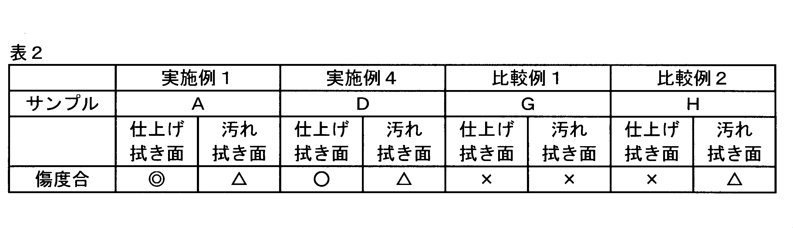
なお、本実施例及び比較例において、不織布坪量、湿潤厚み、拭き取り性、摩擦堅牢度は、以下のようにして測定した。
[不織布坪量]
不織布から、3回分のサンプル片(10mm×10mm)を切り出す。サンプル片の質量を直示天秤(例えば、研精工業株式会社製 電子天秤HF-300)で測定し、3回分のサンプル片の質量の平均値から算出されたサンプル片の単位面積当たりの質量(g/m2)を、不織布の坪量とする。
不織布から、3回分のサンプル片(10mm×10mm)を切り出す。サンプル片の質量を直示天秤(例えば、研精工業株式会社製 電子天秤HF-300)で測定し、3回分のサンプル片の質量の平均値から算出されたサンプル片の単位面積当たりの質量(g/m2)を、不織布の坪量とする。
[湿潤厚み]
不織布に、イオン交換水を、不織布の質量に対して250質量%の量(含浸率)で含浸させ、15cm2の測定子を備えた厚み計((株)大栄科学精器製作所製 型式FS-60DS)を使用して、3gf/cm2の測定荷重の測定条件で、不織布の厚みを測定する。1つの測定用試料について3ヶ所の厚みを測定し、3ヶ所の厚みの平均値を湿潤厚みとする。
不織布に、イオン交換水を、不織布の質量に対して250質量%の量(含浸率)で含浸させ、15cm2の測定子を備えた厚み計((株)大栄科学精器製作所製 型式FS-60DS)を使用して、3gf/cm2の測定荷重の測定条件で、不織布の厚みを測定する。1つの測定用試料について3ヶ所の厚みを測定し、3ヶ所の厚みの平均値を湿潤厚みとする。
[拭き取り性]
模擬汚れとして、カーボンブラック(Carbon Black、米山薬品工業(株)製)12.6質量%、牛脂極度硬化油20.8質量%、流動パラフィン質量66.6%の配合比率のペーストを調製する。そのペーストとヘキサンを85:15(質量比)の割合で混ぜ合わせる。ヘキサン希釈ペーストをガラス板上に0.05mL滴下する。高温高湿室(20℃、湿度60%)で24時間乾燥後、色味をスキャナー(Epson製Calorio GT-750)でスキャンする。テスター産業株式会社の摩擦係数測定装置で、150mm/分、加重60gの条件にて拭取り試験(1回)を行う。試験後、色味の変化をスキャナーでスキャンし、スキャンした面積のうち16.9mm×16.9mm面積の色味の変化率を次式により算出し、汚れ除去率とする。
汚れ除去率(%)=(C0-C1)/C0×100
模擬汚れとして、カーボンブラック(Carbon Black、米山薬品工業(株)製)12.6質量%、牛脂極度硬化油20.8質量%、流動パラフィン質量66.6%の配合比率のペーストを調製する。そのペーストとヘキサンを85:15(質量比)の割合で混ぜ合わせる。ヘキサン希釈ペーストをガラス板上に0.05mL滴下する。高温高湿室(20℃、湿度60%)で24時間乾燥後、色味をスキャナー(Epson製Calorio GT-750)でスキャンする。テスター産業株式会社の摩擦係数測定装置で、150mm/分、加重60gの条件にて拭取り試験(1回)を行う。試験後、色味の変化をスキャナーでスキャンし、スキャンした面積のうち16.9mm×16.9mm面積の色味の変化率を次式により算出し、汚れ除去率とする。
汚れ除去率(%)=(C0-C1)/C0×100
ただし、C0は拭き取り前の色味であり、C1は拭き取り後の色味である。
汚れ除去率が大きいほど、汚れが除去できていると判断できる。N数=3で測定し、3回の平均値を汚れ除去率とする。
仕上げ拭き面(すなわち、疎水性不織布層が存在する面であって、高圧水蒸気処理を行った面)、及びその裏面の汚れ拭き面(すなわち、親水性不織布層が存在する面)のそれぞれの汚れ除去率は、不織布のMD方向とCD方向の汚れ除去率の幾何平均とする。
汚れ除去率が大きいほど、汚れが除去できていると判断できる。N数=3で測定し、3回の平均値を汚れ除去率とする。
仕上げ拭き面(すなわち、疎水性不織布層が存在する面であって、高圧水蒸気処理を行った面)、及びその裏面の汚れ拭き面(すなわち、親水性不織布層が存在する面)のそれぞれの汚れ除去率は、不織布のMD方向とCD方向の汚れ除去率の幾何平均とする。
[摩擦堅牢度]
不織布サンプル片(長さ200mm、幅300mm)を染色物摩擦堅牢度試験機((株)大栄科学精機製作所製)にセットし、機器の摩擦面に布テープ(日東電工(株)製No.753)を装着し、該布テープの非接着面側で200gの荷重下で往復させた。そして不織布サンプル片の仕上げ拭き面に破れが発生するまでの回数を不織布サンプル片のMD方向及びCD方向のそれぞれにおいて測定する。
不織布サンプル片(長さ200mm、幅300mm)を染色物摩擦堅牢度試験機((株)大栄科学精機製作所製)にセットし、機器の摩擦面に布テープ(日東電工(株)製No.753)を装着し、該布テープの非接着面側で200gの荷重下で往復させた。そして不織布サンプル片の仕上げ拭き面に破れが発生するまでの回数を不織布サンプル片のMD方向及びCD方向のそれぞれにおいて測定する。
[寒天擦過試験]
寒天擦過試験は、以下のようにして行う。
アズワン株式会社製標準寒天の生培地の上に不織布サンプルを載置し、さらにサンプル上に直径27mm、質量75gの錘を載せ、引っ張り速度100mm/分で不織布サンプルを水平に引っ張ったときの、寒天培地の傷度合を目視で評価する。
なお、表2中、「◎」、「○」、「△」、及び「×」の評価基準は以下の通りとする。
「◎」:寒天培地上の傷の深さが浅く、目視で僅かに確認可能なレベルである。
「○」:寒天培地上の傷の深さが比較的浅いが、目視で確認可能なレベルである。
「△」:寒天培地上の傷の深さがやや深く、少ないながら清拭すべき面を傷つける虞が想定されるレベルである。
「×」:寒天培地上の傷が深く、清拭すべき面を傷つける虞があるレベルである。
寒天擦過試験は、以下のようにして行う。
アズワン株式会社製標準寒天の生培地の上に不織布サンプルを載置し、さらにサンプル上に直径27mm、質量75gの錘を載せ、引っ張り速度100mm/分で不織布サンプルを水平に引っ張ったときの、寒天培地の傷度合を目視で評価する。
なお、表2中、「◎」、「○」、「△」、及び「×」の評価基準は以下の通りとする。
「◎」:寒天培地上の傷の深さが浅く、目視で僅かに確認可能なレベルである。
「○」:寒天培地上の傷の深さが比較的浅いが、目視で確認可能なレベルである。
「△」:寒天培地上の傷の深さがやや深く、少ないながら清拭すべき面を傷つける虞が想定されるレベルである。
「×」:寒天培地上の傷が深く、清拭すべき面を傷つける虞があるレベルである。
表1により、本発明の実施例の不織布は、従来例である比較例1の不織布と比べて、汚れの拭き取り性能が顕著に優れるとともに、摩擦堅牢性は同等に優れていることが確認された。
表2により、本発明の実施例の不織布は、比較例1及び2の不織布と比べて、清拭すべき面に対する傷つけ易さが著しく低いことが確認された。
1 不織布
3 親水性不織布層
5 畝部
7 溝部
9 疎水性不織布層
11 畝部
13 溝部
15 接合部
17 点状エンボス部
19 線状エンボス部
21 汚れ拭き面
23 仕上げ拭き面
F 第1方向
S 第2方向
T 厚さ方向
3 親水性不織布層
5 畝部
7 溝部
9 疎水性不織布層
11 畝部
13 溝部
15 接合部
17 点状エンボス部
19 線状エンボス部
21 汚れ拭き面
23 仕上げ拭き面
F 第1方向
S 第2方向
T 厚さ方向
Claims (14)
- 親水性繊維を50質量%以上含む親水性不織布層と、
疎水性繊維を50質量%以上含む疎水性不織布層と、
前記親水性不織布層と前記疎水性不織布層とを接合する接合部と、
を備え、
前記疎水性繊維が、繊度が0.3dtex以下の極細繊維を30質量%以上含む、
ことを特徴とするウェットワイプス用不織布。 - 前記親水性不織布層及び前記接合部は、第1の熱融着性繊維を含み、
前記疎水性不織布層及び前記接合部は、第2の熱融着性繊維を含み、
前記接合部は、前記第1の熱融着性繊維と前記第2の熱融着性繊維とが融着しているエンボス部である、請求項1に記載のウェットワイプス用不織布。 - 前記親水性不織布層において、前記第1の熱融着性繊維は、融着していない、請求項2に記載のウェットワイプス用不織布。
- 前記親水性不織布層は、スパンレース不織布層である、請求項1~3のいずれか一項に記載のウェットワイプス用不織布。
- 前記疎水性不織布層は、前記親水性不織布層と対向する面と反対の面において、畝溝構造を有する、請求項1~4のいずれか一項に記載のウェットワイプス用不織布。
- 前記疎水性不織布層が、繊度が0.1dtex未満の超極細繊維を30質量%以上含む、請求項1~5のいずれか一項に記載のウェットワイプス用不織布。
- 前記疎水性不織布層が、前記疎水性繊維を70質量%以上含む、請求項1~6のいずれか一項に記載のウェットワイプス用不織布。
- 前記親水性繊維が、2.5mm~8.0mmの平均繊維長を有するセルロース系繊維と、パルプ繊維とを、親水性繊維の質量に基づいて、それぞれ、30~90質量%及び10~70質量%含む、請求項1~7のいずれか一項に記載のウェットワイプス用不織布。
- 親水性繊維を50質量%以上含む親水性不織布層を形成する工程と、
疎水性繊維を50質量%以上含む疎水性不織布層であって、前記疎水性繊維が、繊度が0.3dtex以下の極細繊維を30質量%以上含むものを形成する工程と、
前記親水性不織布層と前記疎水性不織布層との接合部を形成する工程と、
を含むことを特徴とするウェットワイプス用不織布の製造方法。 - 前記親水性不織布層及び前記接合部は、第1の熱融着性繊維を含み、
前記疎水性不織布層及び前記接合部は、第2の熱融着性繊維を含み、
前記接合部を形成する工程において、熱エンボス加工により前記接合部を形成する、
請求項9に記載の製造方法。 - 前記親水性不織布層を形成する工程において、
前記親水性不織布層は、前記親水性繊維と前記第1の熱融着性繊維とを含む第1のウェブを形成し、前記第1のウェブに対して水流交絡を行って形成される、請求項10に記載の製造方法。 - 前記第2の熱融着性繊維は、前記第1の熱融着性繊維よりも融点が低く、
前記疎水性不織布層を形成する工程において、
前記疎水性不織布層は、前記親水性不織布層の上に、前記0.3dtex以下の極細繊維と前記第2の熱融着性繊維とを含む第2のウェブを形成した後、前記第2のウェブに、前記第2の熱融着性繊維の融点よりも高く、前記第1の熱融着性繊維の融点よりも低い温度でスチームジェット加工を施して、前記第2のウェブの前記第2の熱融着性繊維を融着させて形成される、請求項11に記載の製造方法。 - 前記スチームジェット加工において、配列された複数のノズルからスチームジェットを噴射して、前記第2のウェブに、前記スチームジェットが衝突して形成される溝部の列と、前記溝部の列の間にスチームで膨張されて形成される畝部の列とからなる畝溝の構造を付与する、請求項12に記載の製造方法。
- 前記接合部を形成する工程において、前記疎水性不織布層が存在する面にエンボスロールが、前記親水性不織布層が存在する面にアンビルロールが、それぞれ当接する、請求項10~13のいずれか一項に記載の製造方法。
Applications Claiming Priority (2)
| Application Number | Priority Date | Filing Date | Title |
|---|---|---|---|
| JP2016042552A JP6960719B2 (ja) | 2016-03-04 | 2016-03-04 | ウェットワイプス用不織布及びその製造方法 |
| JP2016-042552 | 2016-03-04 |
Publications (1)
| Publication Number | Publication Date |
|---|---|
| WO2017149903A1 true WO2017149903A1 (ja) | 2017-09-08 |
Family
ID=59742689
Family Applications (1)
| Application Number | Title | Priority Date | Filing Date |
|---|---|---|---|
| PCT/JP2016/087429 Ceased WO2017149903A1 (ja) | 2016-03-04 | 2016-12-15 | ウェットワイプス用不織布及びその製造方法 |
Country Status (2)
| Country | Link |
|---|---|
| JP (1) | JP6960719B2 (ja) |
| WO (1) | WO2017149903A1 (ja) |
Cited By (1)
| Publication number | Priority date | Publication date | Assignee | Title |
|---|---|---|---|---|
| JP7569958B1 (ja) * | 2024-06-11 | 2024-10-18 | ユニ・チャーム株式会社 | 清掃シート |
Families Citing this family (10)
| Publication number | Priority date | Publication date | Assignee | Title |
|---|---|---|---|---|
| JP6735986B2 (ja) * | 2017-08-09 | 2020-08-05 | 株式会社北電子 | 遊技機 |
| JP6901666B2 (ja) * | 2017-08-09 | 2021-07-14 | 株式会社北電子 | 遊技機 |
| JP7065604B2 (ja) * | 2017-12-28 | 2022-05-12 | ユニ・チャーム株式会社 | 繊維不織布シート |
| JP7065603B2 (ja) * | 2017-12-28 | 2022-05-12 | ユニ・チャーム株式会社 | 繊維不織布シート |
| JP7065607B2 (ja) * | 2017-12-28 | 2022-05-12 | ユニ・チャーム株式会社 | 繊維不織布シート |
| JP7065605B2 (ja) * | 2017-12-28 | 2022-05-12 | ユニ・チャーム株式会社 | 繊維不織布シート |
| JP7065606B2 (ja) * | 2017-12-28 | 2022-05-12 | ユニ・チャーム株式会社 | 繊維不織布シート |
| JP7097705B2 (ja) * | 2018-01-24 | 2022-07-08 | 花王株式会社 | ワイピングシートの製造方法 |
| JP6575034B2 (ja) * | 2018-08-06 | 2019-09-18 | 株式会社北電子 | 遊技機 |
| JP2021178127A (ja) * | 2020-05-15 | 2021-11-18 | ユニ・チャーム株式会社 | 清掃用シート |
Citations (6)
| Publication number | Priority date | Publication date | Assignee | Title |
|---|---|---|---|---|
| JP2002209823A (ja) * | 2000-11-17 | 2002-07-30 | Kao Corp | 硬質表面用艶出し洗浄シート |
| JP2004344369A (ja) * | 2003-05-22 | 2004-12-09 | Meisei Sansho Kk | 清掃シート |
| JP2005287894A (ja) * | 2004-04-01 | 2005-10-20 | Uni Charm Corp | ワイパーおよびその製造方法 |
| JP2010201112A (ja) * | 2009-03-06 | 2010-09-16 | Daio Paper Corp | 清掃用シート |
| JP2015190098A (ja) * | 2014-03-28 | 2015-11-02 | ユニ・チャーム株式会社 | ウェットティッシュ、及びウェットティッシュの製造方法 |
| JP2015192777A (ja) * | 2014-03-31 | 2015-11-05 | ダイワボウホールディングス株式会社 | 対物ワイピング用シートおよびその製造方法 |
Family Cites Families (5)
| Publication number | Priority date | Publication date | Assignee | Title |
|---|---|---|---|---|
| JP2525862Y2 (ja) * | 1990-09-17 | 1997-02-12 | 旭化成工業株式会社 | ワイピングクロス |
| JPH0833588A (ja) * | 1994-07-25 | 1996-02-06 | Fushimi:Kk | タオル |
| JP2007222609A (ja) * | 2006-01-24 | 2007-09-06 | Toray Ind Inc | ワイピングクロス |
| JP2009160024A (ja) * | 2007-12-28 | 2009-07-23 | Hiroko Yoshimoto | 携帯用ワイピンググッズ |
| JP6253238B2 (ja) * | 2012-05-28 | 2017-12-27 | 花王株式会社 | 清掃用シート及びその製造方法 |
-
2016
- 2016-03-04 JP JP2016042552A patent/JP6960719B2/ja active Active
- 2016-12-15 WO PCT/JP2016/087429 patent/WO2017149903A1/ja not_active Ceased
Patent Citations (6)
| Publication number | Priority date | Publication date | Assignee | Title |
|---|---|---|---|---|
| JP2002209823A (ja) * | 2000-11-17 | 2002-07-30 | Kao Corp | 硬質表面用艶出し洗浄シート |
| JP2004344369A (ja) * | 2003-05-22 | 2004-12-09 | Meisei Sansho Kk | 清掃シート |
| JP2005287894A (ja) * | 2004-04-01 | 2005-10-20 | Uni Charm Corp | ワイパーおよびその製造方法 |
| JP2010201112A (ja) * | 2009-03-06 | 2010-09-16 | Daio Paper Corp | 清掃用シート |
| JP2015190098A (ja) * | 2014-03-28 | 2015-11-02 | ユニ・チャーム株式会社 | ウェットティッシュ、及びウェットティッシュの製造方法 |
| JP2015192777A (ja) * | 2014-03-31 | 2015-11-05 | ダイワボウホールディングス株式会社 | 対物ワイピング用シートおよびその製造方法 |
Cited By (2)
| Publication number | Priority date | Publication date | Assignee | Title |
|---|---|---|---|---|
| JP7569958B1 (ja) * | 2024-06-11 | 2024-10-18 | ユニ・チャーム株式会社 | 清掃シート |
| WO2025258450A1 (ja) * | 2024-06-11 | 2025-12-18 | ユニ・チャーム株式会社 | 清掃シート |
Also Published As
| Publication number | Publication date |
|---|---|
| JP2017153890A (ja) | 2017-09-07 |
| JP6960719B2 (ja) | 2021-11-05 |
Similar Documents
| Publication | Publication Date | Title |
|---|---|---|
| JP6960719B2 (ja) | ウェットワイプス用不織布及びその製造方法 | |
| KR100501415B1 (ko) | 와이프시이트 | |
| KR101107492B1 (ko) | 티슈 웹 및 다른 부직포를 포함하는 복합 구조체 | |
| JP6423578B2 (ja) | 積層不織布、その製造方法及びこれを用いた不織布製品 | |
| JP3559533B2 (ja) | 絡合不織布とこれを用いた清拭シートおよび湿潤性シート | |
| EP3387172B1 (en) | Patterned nonwoven material | |
| TWI564450B (zh) | Manufacture of nonwovens and nonwovens | |
| JP2017101341A (ja) | ウェットワイピングシート用不織布および対人用ウェットワイピングシート | |
| JP7307632B2 (ja) | 複合型不織布の製造方法 | |
| JP2022003173A (ja) | 複合型不織布およびその製造方法 | |
| JP6943467B2 (ja) | 複合不織布製造装置及び複合不織布の製造方法 | |
| KR101155115B1 (ko) | 3 레이어 부직포 및 그 제조방법 | |
| TW201340923A (zh) | 濕擦拭物及其製造方法 | |
| JP7324014B2 (ja) | 複合型不織布とその製造方法 | |
| JP7128682B2 (ja) | 不織布ワイパーおよびその製造方法 | |
| JP5313488B2 (ja) | ウェットワイパー用基材シート及びウェットワイパー | |
| JP2018535126A (ja) | 天然繊維ウェブ層を含む不織複合体及びその形成方法 | |
| JP6104550B2 (ja) | 不織布を製造する方法 | |
| JP2022138533A (ja) | 複合型不織布およびその製造方法 | |
| JP3967848B2 (ja) | 清掃用不織布およびその製造方法 | |
| JP2002263043A (ja) | ワイピング用不織布 | |
| JP2023006231A (ja) | 複合型不織布およびその製造方法 | |
| JP7237571B2 (ja) | 複合型不織布とその製造方法 | |
| JP5755173B2 (ja) | 不織布および不織布の製造方法 | |
| JP6016769B2 (ja) | 不織布及び不織布の製造方法 |
Legal Events
| Date | Code | Title | Description |
|---|---|---|---|
| NENP | Non-entry into the national phase |
Ref country code: DE |
|
| 121 | Ep: the epo has been informed by wipo that ep was designated in this application |
Ref document number: 16892737 Country of ref document: EP Kind code of ref document: A1 |
|
| 122 | Ep: pct application non-entry in european phase |
Ref document number: 16892737 Country of ref document: EP Kind code of ref document: A1 |