WO2017149881A1 - ラベル貼付装置 - Google Patents
ラベル貼付装置 Download PDFInfo
- Publication number
- WO2017149881A1 WO2017149881A1 PCT/JP2016/086092 JP2016086092W WO2017149881A1 WO 2017149881 A1 WO2017149881 A1 WO 2017149881A1 JP 2016086092 W JP2016086092 W JP 2016086092W WO 2017149881 A1 WO2017149881 A1 WO 2017149881A1
- Authority
- WO
- WIPO (PCT)
- Prior art keywords
- label
- push
- tag
- double
- transport
- Prior art date
Links
Images


Classifications
-
- B—PERFORMING OPERATIONS; TRANSPORTING
- B65—CONVEYING; PACKING; STORING; HANDLING THIN OR FILAMENTARY MATERIAL
- B65C—LABELLING OR TAGGING MACHINES, APPARATUS, OR PROCESSES
- B65C9/00—Details of labelling machines or apparatus
- B65C9/26—Devices for applying labels
Definitions
- the present invention relates to a label sticking device for sticking a label to an adherend such as a luggage.
- JP 2006-181991A uses a suction plate that sucks and holds the issued double-sided print label by separately printing the front-side label and the back-side label and then bonding them together.
- An apparatus for attaching to (package) is disclosed.
- a double-sided printing label used for delivery of a package has a part that becomes a slip on which thin papers are superimposed and a part that affixes the slip to an adherend through an adhesive layer.
- the issued double-sided printing label may adhere to a conveyance member, and in that case, there exists a problem that delivery of a double-sided printing label to an adsorption
- suction plate is not performed smoothly.
- the present invention has been made in view of the above problems, and an object of the present invention is to provide a label affixing device in which a label is smoothly delivered to an adsorption portion.
- a label affixing device for affixing the label to an adherend with an adhesive layer, a conveyance mechanism for conveying the label, and the label conveyed by the conveyance mechanism, A sticking mechanism for sticking to the adherend, and the transport mechanism includes a transport unit that transports the label, and a push-up unit that pushes up the label transported by the transport unit from the transport unit.
- a labeling device is provided.
- the label transported by the transport unit is received by the sticking mechanism while being pushed up from the transport unit by the push-up unit. For this reason, it is suppressed that the adhesive layer of a label sticks to a conveyance part, and delivery of a label is performed smoothly.
- FIG. 1 is a perspective view of a label sticking device according to an embodiment of the present invention.
- FIG. 2 is a schematic configuration diagram of the label sticking device according to the embodiment of the present invention.
- FIG. 3 is a diagram of the double-sided printing label as viewed from the front side. 4 is a cross-sectional view taken along the line IV-IV in FIG.
- FIG. 5 shows a state in which the tag label is affixed to the package, and corresponds to the VV cross-sectional view of FIG.
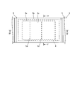
- FIG. 6 is a plan view of the label sticking mechanism.
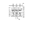
- FIG. 7 is a front view of the label sticking mechanism.
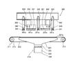
- FIG. 8 is a side view of the label sticking mechanism.
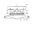
- FIG. 9A is a side view showing the operation of the label sticking mechanism.
- FIG. 9A is a side view showing the operation of the label sticking mechanism.
- FIG. 9B is a side view showing the operation of the label sticking mechanism.
- FIG. 9C is a side view showing the operation of the label attaching mechanism.
- FIG. 9D is a side view showing the operation of the label sticking mechanism.
- FIG. 9E is a side view showing the operation of the label attaching mechanism.
- FIG. 9F is a side view showing the operation of the label attaching mechanism.
- the label sticking device 10 prints a double-sided printing label 3 and issues a label label 2 (double-sided printing label), and a roller for the issued label label 2
- the double-sided printing label 3 will be described with reference to FIGS.
- the thickness of the double-sided printing label 3 is exaggerated to be larger than the actual thickness for convenience.
- the double-sided printing label 3 is a continuous label body in which a single-leaf surface-side label 5 is bonded to a belt-like back surface-side label 4.
- the front side label 5 is divided into an outer edge part 5b and an inner part 5c by a circular perforation 5a as a surface cut line.
- the inner portion 5c is partitioned into a plurality of regions by perforations 5d.
- the back surface side label 4 is divided into an outer edge portion 4b and an inner portion 4c by a circumferential cut 4a as a back surface cut line.
- the inner side part 4c is divided into the edge part 4e and the center part 4f in the longitudinal direction of the back surface side label 4 by the two slit eyes 4d.
- a pressure-sensitive adhesive layer 5 e is provided in a rectangular frame-like region on the outer edge portion 5 b of the front surface side label 5, and a release agent layer 4 g is provided on the outer edge portion 4 b of the back surface side label 4.
- the front surface side label 5 and the back surface side label 4 are bonded together with the pressure-sensitive adhesive layer 5e and the release agent layer 4g facing each other.
- FIG. 5 is a view showing a state in which the tag label 2 issued separately from the double-sided printing label 3 is attached to the package 1.
- the single leaflet label 2 has inner portions 4c and 5c that become slips on which thin papers are stacked, and a frame-shaped outer edge portion 5b that is attached to the luggage 1 so as to surround the slip.
- the outer edge portion 5b is affixed to the luggage 1 with an adhesive layer 5e provided on the back surface thereof.
- the inner side portion 4c of the back surface side label 4 is covered with the front surface side label 5 and cannot be seen from the outside when the label 2 is attached to the load 1.
- the gantry 105 is provided with a supply unit 101 on which the double-sided printing label 3 is placed.
- the fanfold type double-sided printing label 3 is placed on the supply unit 101 in a folded state.
- a stock unit 102 is provided alongside the supply unit 101.
- a spare double-sided printing label 3 is placed on the stock unit 102.
- a guide 103 for guiding the double-sided printing label 3 is provided above the supply unit 101.
- a label detection sensor 104 for detecting the presence or absence of the double-sided printing label 3 is provided on the side of the double-sided printing label 3 as shown in FIG.
- the controller 290 stops the operation of the label sticking device 10 or the label sticking device when the remaining amount of the label 3 for double-sided printing is reduced in the supply unit 101 according to the detection signal of the label detection sensor 104. 10 will issue a warning.
- the label issuing apparatus 100 includes a thermal double-sided printing apparatus 110 that performs printing by heating the double-sided printing label 3 that is a thermal medium.
- the double-sided printing apparatus 110 performs printing on the casing 111, the first thermal head 112 for printing on the front surface of the double-sided printing label 3, and the back surface of the double-sided printing label 3.
- the first platen drive motor 116 for driving the first platen roller 114, the second platen drive motor 117 for driving the second platen roller 115 via a belt, a gear or the like, and the position of the double-sided printing label 3 are detected.
- the double-sided printing label 3 is supplied into the housing 111 from a supply port 111a provided in the housing 111 of the double-sided printing apparatus 110 with the front side label 5 facing upward, and the first thermal head 112 and the first platen roller 114 are supplied. And between the second thermal head 113 and the second platen roller 115.
- the surface-side label 5 which is a thermal medium is self-colored by the heat of the heating element and printing is performed.
- the heating element of the second thermal head 113 is energized, the back side label 4 which is a thermal medium is self-colored by the heat of the heating element and printing is performed.
- the inner side 5c of the front side label 5 is used as the front side printing area of the double-sided printing label 3, and the central part 4f of the back side label 4 is used as the rear side printing area of the double-sided printing label 3.
- the front surface printing area of the double-sided printing label 3 for example, delivery destination information of the package 1 is printed.
- the back side printing area of the double-sided printing label 3 for example, information to be kept confidential such as the product name and the amount of money is printed.
- the double-sided printing label 3 is conveyed to the downstream side and provided in the housing 111. It is discharged from the discharge port 111b.
- the first platen roller 114 and the second platen roller 115 rotate in synchronism with each other so that the double-sided printing label 3 is not slackened or tensioned.
- the position detection sensor 118 detects a position detection eye mark printed in advance on the back surface side label 4 of the double-sided printing label 3 at a predetermined interval, and includes a first thermal head 112 and a second thermal head. This is used to detect the relative position of the double-sided printing label 3 with respect to 113.
- the controller 290 controls the operation of the first platen drive motor 116 and the second platen drive motor 117 according to the detection signal of the position detection sensor 118.
- the label issuing device 100 includes a label peeling mechanism 120 that separates the single label tag 2 from the printed double-sided label 3.
- the label peeling mechanism 120 is disposed on the downstream side of the double-sided printing apparatus 110, peels the outer edge portion 4b of the back surface side label 4 from the front surface side label 5, and the front surface side label 5 and the inner side portion 4c of the back surface side label 4; This is a mechanism for separating the single-leaf tag label 2 constituted by the double-sided printing label 3.
- the label peeling mechanism 120 includes a label winder 121 that winds the outer edge 4b of the back side label 4 peeled from the front side label 5, and a winder drive that drives the label winder 121 via a belt, a gear, or the like.
- a peeling plate 123 that comes into contact with the back surface of the double-sided printing label 3 discharged from the double-sided printing apparatus 110 and peels the outer edge 4b of the back-side label 4 from the front-side label 5 and the peeling from the front-side label 5
- Guide rollers 124 to 127 for guiding the outer edge portion 4b of the rear surface side label 4 to the label winder 121.
- the guide roller 126 is driven by a motor (not shown) so as to feed the outer edge portion 4b of the back side label 4 sandwiched between the guide roller 127 and the guide roller 126.
- the label winder 121 includes a pair of rotating plates 121a and four winding shafts 121b extending across the pair of rotating plates 121a.
- the outer edge part 4b of the back surface side label 4 engages with the four winding shafts 121b and is wound between the two rotating plates 121a.
- the guide roller 126 and the label winder 121 are rotationally driven in both forward and reverse directions in synchronization with the first platen roller 114 and the second platen roller 115 of the duplex printing apparatus 110. Thereby, when the label winder 121 winds up the outer edge part 4b of the back surface side label 4, it does not occur that the double-sided printing label 3 or the outer edge part 4b of the back surface side label 4 is loosened or tensioned. It has become.
- the outer edge portion 4 b of the back surface side label 4 is sequentially peeled from the front surface side label 5 by being bent at the tip position of the peeling plate 123 as it is wound around the label winder 121. Even if the outer edge part 4b peels from the surface side label 5, the inner side part 4c of the back surface side label 4 does not peel from the surface side label 5, but is separated from the outer edge part 4b by the cut 4a. Thus, the tag label 2 having the front side label 5 and the inner side portion 4c of the back side label 4 is issued separately from the double-sided printing label 3.
- the label pasting mechanism 200 receives a label mechanism 2 that transports a tag label 2 issued from the label issuing device 100, and a label label 2 that is transported by the transport mechanism 210. And a pasting mechanism 240 for pasting to the head.
- the transport mechanism 210 is provided with a plurality (two) of transport conveyors 211 (transport units) side by side.
- the transport conveyor 211 is a transport unit that transports the tag label 2 that is issued separately from the double-sided printing label 3 by the label peeling mechanism 120 to a delivery position to the sticking mechanism 240.
- the number of transport conveyors 211 provided in the transport mechanism 210 is not limited to two, and is arbitrarily set according to the size of the label 2 and the like.
- the conveyor 211 includes a belt 212 for conveying the label 2, rollers 214 and 215 around which the belt 212 is wound, and a conveyor drive motor that drives the belt 212 via a belt, a gear, or the like. 213.
- the belt 212 circulates in synchronization with the first platen roller 114, the second platen roller 115, and the label winder 121 of the duplex printing apparatus 110. As a result, the tag label 2 issued separately from the double-sided printing label 3 is transferred from the label issuing device 100 to the transport conveyor 211 without delay.
- a label detection sensor 216 is provided in the vicinity of the transport conveyor 211.
- the label detection sensor 216 is a reflective photoelectric sensor that detects the presence or absence of the label 2.
- the controller 290 controls the operation of the transport conveyor 211 so as to transport the tag label 2 to the delivery position to the sticking mechanism 240 in accordance with the detection signal of the label detection sensor 216.
- the adhesive layer 5e is exposed on the back side of the label 2 because the outer edge 4b of the back side label 4 is peeled off from the front side label 5.
- a release agent layer (not shown) is provided on the surface of the belt 212. This prevents the tag label 2 from sticking to the belt 212 via the adhesive layer 5e. Further, the adhesive of the adhesive layer 5e is prevented from adhering to the belt 212.
- the transport conveyor 211 may include a negative pressure generator that has a plurality of holes in the belt 212 and generates a negative pressure in each hole. In this case, the tag label 2 is conveyed while being attracted to the belt 212, thereby preventing the tag label 2 from slipping or being displaced on the belt 212.
- the transport mechanism 210 is provided with a push-up unit 220 that pushes up the tag label 2 transported by the transport conveyor 211 from the transport conveyor 211.
- the push-up unit 220 includes a plurality (six blades) of blades 221 (push-up members) arranged along with the conveyor 211 and actuators 222 that raise and lower the blades 221.
- the push-up portion 220 is provided with three sets of two blades 221 as one set.
- Each set composed of a set of two blades 221 is arranged so as to sandwich each conveyance conveyor 211 and is in contact with both sides and the center of the label 2.
- each blade 221 is fixedly attached to the push-up frame 225.
- the push-up frame 225 is driven in the vertical direction by the actuator 222.
- each blade 221 protrudes downward from the belt 212 of the conveyor 211 as shown in FIGS. 8 and 9A, and protrudes upward from the belt 212 of the conveyor 211 as shown in FIG. 9B. It moves up and down between the protruding position where the label 2 is lifted.
- the thin plate-like blade 221 is disposed so as to extend along the side of the conveyor 211 and to extend in the vertical direction (vertical direction).
- the blade 221 has a tip 221a extending linearly at the top.
- the width T1 (see FIG. 6) of the tip 221a is set to be smaller than the width T5 (see FIG. 5) of the adhesive layer 5e of the tag label 2, and is in linear contact with the adhesive layer 5e.
- a release agent layer (not shown) is provided on the surface of the tip 221a. This prevents the tag label 2 from sticking to the blade 221 via the adhesive layer 5e. Further, the adhesive of the adhesive layer 5e is prevented from adhering to the blade 221.
- the two blades 221 are coupled via a plurality (two) of spacers 224.
- the two blades 221 have a predetermined interval. Specifically, the blade installation width T2 (see FIGS. 6 and 7) where the tips 221a of the two blades 221 are provided is set smaller than the suction width T3 (see FIGS. 6 and 7) of the suction pad 241 described later. Is done.
- the two blades 221 are arranged to face the suction pad 241.
- the number of blades 221 facing the suction pad 241 is not limited to two, and is arbitrarily set according to the size of the suction pad 241 and the like.
- the label detection sensor 216 for detecting the presence / absence of the label 2 described above may be provided so as to be disposed between the two blades 221 aligned with each other.
- the label detection sensor can be disposed so as to face the center of the label 2. Thereby, the label detection sensor 216 can accurately detect the presence / absence of the label 2 on the blade 221.
- the pasting mechanism 240 includes a plurality (eight) of suction pads 241 (suction portions) for sucking the label 2, pipes 242 to which the suction pads 241 are connected, and each pipe. Elevating frame 245 to which 242 is attached.
- the pipe 242 is connected to a negative pressure generator via a pipe (not shown), and guides the negative pressure to the inside of the suction pad 241.
- the suction pad 241 is a suction portion that sucks the label 2 with a negative pressure.
- the number of suction pads 241 is not limited to eight, and can be arbitrarily set according to the size of the tag label 2 and the like.
- the suction pad 241 is formed of an elastic material such as rubber.
- the suction pad 241 is elastically deformed by the negative pressure that sucks the label 2 and contracts in the axial direction (vertical direction).
- the suction pad 241 is formed in a cylindrical shape having a bellows-like cross-sectional shape, and has an annular suction surface 241 a that sucks the tag label 2.
- the diameter of the suction surface 241a is the suction width T3 for sucking the tag label 2.
- the suction pad 241 is not limited to this shape, and may be any one that elastically deforms and expands and contracts due to a pressure change generated inside thereof.
- the eight suction pads 241 are arranged to face the outer edge portion 5 b of the tag label 2.
- a plurality (three or two) of suction pads 241 arranged in the left-right direction in FIG. 6 are arranged so as to face three sets of blades 221 extending in the longitudinal direction of the tag label 2 (left-right direction in FIG. 6). Is done.
- the sticking mechanism 240 includes a support portion 250 that supports the label 2 that is attracted to the suction pad 241.
- the support unit 250 supports the tag label 2 by contacting it. This restricts the tag label 2 from loosening between the suction pads 241.
- the support portion 250 includes a plurality (two) of elastic members 251 that abut on the label 2 that is attracted to the suction pad 241, and a plurality (two) of brackets 253 that attach the elastic members 251 to the lifting frame 245. .
- the two elastic members 251 are arranged so as to extend between the suction pads 241 arranged in three rows in the longitudinal direction of the tag label 2 (left-right direction in FIG. 6).
- the number of elastic members 251 is not limited to two, and is arbitrarily set according to the number of rows of suction pads 241.
- the block-like elastic member 251 has a cubic outer shape and has a support surface 251a extending in the horizontal direction.
- the support surface 251 a is provided so as to face the tag label 2, and comes into contact with the tag label 2 attracted to each suction pad 241.
- the elastic member 251 is formed of a porous material (sponge) having a large number of bubbles formed by foaming rubber such as ethylene propylene rubber (EDPM).
- EDPM ethylene propylene rubber
- the elastic member 251 is attached to the lower surface of the bracket 253 by joining.
- the bracket 253 is fastened to the lifting frame 245 via a plurality of (two) bolts 254.
- the attachment position of the elastic member 251 with respect to the suction pad 241 is adjusted by changing the position where the bracket 253 is fastened to the lifting frame 245.
- the elastic member 251 is attached so as to satisfy the following conditions.
- a non-adsorption state (free state) in which the suction pad 241 is not contracted by a negative pressure
- the suction surface 241a of the suction pad 241 is lowered (separated) by a predetermined amount with respect to the support surface 251a of the elastic member 251.
- the suction state elastic deformation state
- the suction surface 241a of the suction pad 241 is substantially at the same height as the support surface 251a of the elastic member 251.
- the adsorption surface 241a and the support surface 251a are disposed so as to extend on the same straight line.
- the suction pad 241 is contracted by a predetermined amount (for example, about 2 mm) by the negative pressure that sucks the tag label 2, so that the suction surface 241 a that sucks the tag label 2 is below (separated from) the support surface 251 a of the elastic member 251. ) Is set to at least a position that is at the same height as the support surface 251a of the elastic member 251.
- a label detection sensor 248 is provided between the two elastic members 251.
- the label detection sensor 248 is a reflective photoelectric sensor that detects the presence or absence of the label 2.
- the controller 290 determines that there is the tag label 2 in accordance with the detection signal of the label detection sensor 248, and operates the moving mechanism 230 to attach the tag label 2 to the package 1 as will be described later. When there is no tag label 2, the operation of the moving mechanism 230 is stopped.
- the moving mechanism 230 is movable along the fixed frame 231, a horizontal rail 232 extending in a horizontal direction perpendicular to the conveying direction of the roller conveyor 280 on the fixed frame 231, and the horizontal rail 232.
- a moving body 233 provided, an actuator (not shown) that drives the moving body 233, a vertical rail 234 extending in the vertical direction from the moving body 233, a lifting frame 245 that is vertically movable along the vertical rail 234, and a lifting frame 245 And an actuator not shown.
- the moving body 233 moves in the horizontal direction orthogonal to the conveying direction of the roller conveyor 280 by the actuator.
- the moving body 233 includes a label receiving position where the sticking mechanism 240 is located on the transport mechanism 210 (two-dot chain line in FIG. 1), and a label sticking position where the sticking mechanism 240 is located on the roller conveyor 280 (solid line in FIG. 1). , Move between.
- the elevating frame 245 moves up and down with respect to the moving body 233 by an actuator.
- the sticking mechanism 240 moves up and down at each of the position where the tag label 2 is received from the blade 221 and the position where the tag label 2 is stuck on the roller conveyor 280.
- the roller conveyor 280 includes a stopper (not shown), and stops the luggage 1 at the label application position until the application of the tag label 2 to the luggage 1 is completed.
- the stopper of the roller conveyor 280 is released, and the package 1 is conveyed downstream.
- the transport conveyor 211 circulates the belt 212 and transports the label 2 placed on the belt 212 to the delivery position of the sticking mechanism 240.
- the blade 221 is in the retracted position lowered below the belt 212 and does not interfere with the transported label 2.
- the blade 221 rises to the protruding position.
- the tip 221a of the blade 221 protrudes above the belt 212, and the tag label 2 is lifted away from the belt 212.
- each suction pad 241 of the sticking mechanism 240 is lowered.
- each suction pad 241 comes into contact with the tag label 2 before the elastic member 251, and the inside of the suction pad 241.
- the label 2 is adsorbed by the negative pressure introduced to
- each suction pad 241 When each suction pad 241 sucks the tag label 2, each suction pad 241 sandwiches the tag label 2 between the tips 221 a of the blades 221. The tag label 2 is supported in linear contact with the tip 221a of each blade 221.
- each suction pad 241 when each suction pad 241 sucks the label 2, each suction pad 241 contracts due to negative pressure as shown in FIG. 9D, and the suction surface 241 a of each suction pad 241 is substantially the same as the support surface 251 a of the elastic member 251. Come to the same height.
- the label 2 adsorbed to each suction pad 241 is in a state of extending straight by coming into contact with the support surface 251a of each elastic member 251 extending along the same straight line along with the suction surface 241a of the suction pad 241. Supported by
- the moving body 233 moves from the label receiving position (two-dot chain line in FIG. 1) to the label attaching position (solid line in FIG. 1).
- the tag label 2 is attached to the package 1 when the attaching mechanism 240 is lowered.
- the label 2 is attached to the surface to be attached (upper surface) of the luggage 1 without causing wrinkles in a state of extending straight.
- each suction pad 241 and each elastic member 251 elastically deforms following the shape of the surface to be adhered of the luggage 1. .
- the label 2 is stuck via the pressure sensitive adhesive layer 5e by pressing the pressure sensitive adhesive layer 5e against the sticking surface of the load 1 in a wide range.
- the label sticking device 10 receives the tag label 2 transported by the transport mechanism 210 that transports the tag label 2 (label) and the tag label 2 transported by the transport mechanism 210, and pastes it on the package 1 (adherent).
- a pasting mechanism 240 receives the tag label 2 transported by the transport mechanism 210 that transports the tag label 2 (label) and the tag label 2 transported by the transport mechanism 210, and pastes it on the package 1 (adherent).
- the transport mechanism 210 includes a transport conveyor 211 (transport section) that transports the tag label 2 and a push-up unit 220 that pushes up the tag label 2 transported by the transport conveyor 211 from the transport conveyor 211.
- the tag label 2 conveyed by the conveyor 211 is received by the sticking mechanism 240 while being pushed up from the conveyor 211 by the pusher 220.
- the adhesive layer 5e of the tag label 2 is not pressed against the conveyor 211, the adhesive layer 5e of the tag label 2 is suppressed from sticking to the surface of the belt 212, and the delivery of the tag label 2 is prevented. Smoothly done.
- the adhesive of the adhesive layer 5e is prevented from adhering to the conveyance conveyor 211, the state where the conveyance conveyor 211 conveys the tag label 2 smoothly is maintained.
- the sticking mechanism 240 includes a suction pad 241 (suction portion) that sucks the label 2 with a negative pressure, and the push-up portion 220 is provided at a position facing the suction pad 241.
- the suction pad 241 is sucked so that the label 2 is sandwiched between the suction pad 220 and the suction pad 220. Thereby, in the sticking mechanism 240, the tag label 2 is reliably sucked by the suction pad 241.
- suction pad 241 is disposed so as to suck the surface of the tag label 2 opposite to the adhesive layer 5e.
- the suction pad 241 presses the surface of the tag label 2 opposite to the adhesive layer 5e.
- the label 2 is reliably attached to the luggage 1 by the pressure-sensitive adhesive layer 5 e being pressed against the luggage 1 by the suction pad 241.
- the push-up portion 220 includes a blade 221 that comes into linear contact with the tag label 2.
- the blade 221 linearly contacts the pressure-sensitive adhesive layer 5e of the tag label 2, and the contact area with the pressure-sensitive adhesive layer 5e decreases, so the tag label 2 is bonded via the pressure-sensitive adhesive layer 5e. It is prevented. Thereby, it is performed smoothly that the sticking mechanism 240 receives the tag label 2.
- the blade 221 is not limited to the above-described configuration, and has a configuration in which a plurality of pin-shaped protrusions are arranged at intervals to contact the pressure-sensitive adhesive layer 5e of the label 2 in a dotted manner. Also good. In this case, since the contact area with the pressure-sensitive adhesive layer 5e is reduced, the blade 221 can effectively prevent the blade 221 from sticking to the pressure-sensitive adhesive layer 5e.
- the push-up portion 220 is arranged so that the plurality of blades 221 face the suction pad 241 with the tag label 2 interposed therebetween.
- the tag label 2 is supported across the plurality of blades 221, it is possible to suppress the occurrence of bending or the like in a portion facing the suction pad 241. By attracting the suction pad 241 with the tag label 2 sandwiched between the plurality of blades 221, the tag label 2 is reliably sucked.
- the sticking mechanism 240 is configured to receive the label label 2 from the transport mechanism 210 by moving up and down above the transport mechanism 210 and to stick the tag label 2 to the luggage 1 by moving up and down above the load 1.
- the label affixing device 10 receives the tag label 2 from the transport mechanism 210 and reliably affixes the tag label 2 to the package 1.
Landscapes
- Labeling Devices (AREA)
Abstract
ラベル貼付装置は、ラベルを搬送する搬送機構と、搬送機構によって搬送されたラベルを受け取り、被着体に貼付する貼付機構と、備え、搬送機構は、ラベルを搬送する搬送部と、搬送部によって搬送されたラベルを搬送部から押上げる押上部と、を備える。
Description
本発明は、ラベルを荷物等の被着体に貼付するラベル貼付装置に関する。
荷物の配送等に用いられる荷札ラベルには、表面に届け先情報等が印字され、裏面に品名、金額等の秘匿にしたい情報等が印字される両面印字ラベルがある。
JP2006-181991Aには、表面側ラベルと裏面側ラベルとに別々に印字を行った後に貼り合わせて両面印字ラベルを発行し、発行された両面印字ラベルを吸着保持する吸着プレートを用いて被着体(荷物)に貼付する装置が開示されている。
一般に、荷物の配送等に用いられる両面印字ラベルは、薄い紙を重ね合わせた伝票となる部位と、伝票を粘着剤層を介して被着体に貼付する部位と、を有する。
このため、上記の装置では、発行された両面印字ラベルが搬送部材に粘着されることがあり、その場合には、両面印字ラベルを吸着プレートに受け渡すことが円滑に行われないという問題がある。
本発明は、上記の問題点に鑑みてなされたものであり、吸着部へのラベルの受け渡しが円滑に行われるラベル貼付装置を提供することを目的とする。
本発明のある態様によれば、前記ラベルを粘着剤層によって被着体に貼付するラベル貼付装置であって、前記ラベルを搬送する搬送機構と、前記搬送機構によって搬送された前記ラベルを受け取り、前記被着体に貼付する貼付機構と、を備え、前記搬送機構は、前記ラベルを搬送する搬送部と、前記搬送部によって搬送された前記ラベルを前記搬送部から押上げる押上部と、を備えるラベル貼付装置が提供される。
上記態様によれば、搬送部によって搬送されたラベルは、押上部によって搬送部から押上げられた状態で、貼付機構によって受け取られる。このため、ラベルの粘着剤層が搬送部に貼り付くことが抑えられ、ラベルの受け渡しが円滑に行われる。
以下、添付図面を参照しながら本発明の実施形態について説明する。
図1、図2に示すように、ラベル貼付装置10は、両面印字用ラベル3を印字して荷札ラベル2(両面印字ラベル)を発行するラベル発行装置100と、発行された荷札ラベル2をローラコンベア280上の荷物1(被着体)に貼付するラベル貼付機構200と、を備える。
まず、図3から図5を参照して両面印字用ラベル3について説明する。なお、各図において、両面印字用ラベル3は、便宜上、その厚さを実際より大きい寸法に誇張して示している。
図3に示すように、両面印字用ラベル3は、帯状の裏面側ラベル4に単葉の表面側ラベル5を貼り連ねたラベル連続体である。
表面側ラベル5は、表面切り取り線としての周回状のミシン目5aにより外縁部5bと内側部5cとに区画される。また、内側部5cは、ミシン目5dにより複数の領域に区画される。
図4に示すように、裏面側ラベル4は、裏面切り取り線としての周回状の切り目4aにより外縁部4bと内側部4cとに区画される。内側部4cは、2本のスリット目4dにより裏面側ラベル4の長手方向における端部4eと中央部4fとに区画される。
表面側ラベル5の外縁部5bには粘着剤層5eが四角形の枠状の領域に設けられ、裏面側ラベル4の外縁部4bには剥離剤層4gが設けられる。表面側ラベル5と裏面側ラベル4とは、粘着剤層5eと剥離剤層4gとを対向して貼り合わされる。
図5は、両面印字用ラベル3から分離して発行された荷札ラベル2が荷物1に貼付された状態を示す図である。単葉の荷札ラベル2は、薄い紙を重ね合わせた伝票となる内側部4c、5cと、伝票を囲むようにして荷物1に貼付される枠状の外縁部5bと、を有する。外縁部5bは、その裏面に設けられた粘着剤層5eにより荷物1に貼付される。裏面側ラベル4の内側部4cは、荷札ラベル2を荷物1に貼付した状態では表面側ラベル5に覆われて外部から見えないようになっている。
次に、図1、図2を参照してラベル発行装置100について説明する。
図1に示すように、架台105には、両面印字用ラベル3が置かれる供給部101が設けられる。ファンフォールド型の両面印字用ラベル3は、折り畳まれた状態で、供給部101に置かれる。供給部101と並んでストック部102が設けられる。ストック部102には、予備の両面印字用ラベル3が置かれる。
供給部101の上方には、両面印字用ラベル3を案内するガイド103が設けられる。両面印字用ラベル3の側方には、図2に示すように両面印字用ラベル3の有無を検出するラベル検出センサ104が設けられる。コントローラ290は、ラベル検出センサ104の検出信号に応じて、供給部101に両面印字用ラベル3のラベル残量が少なくなった場合に、ラベル貼付装置10の作動を停止させる、もしくは、ラベル貼付装置10が警告を発するようにする。
ラベル発行装置100は、感熱媒体である両面印字用ラベル3を熱して印字を行う感熱方式の両面プリント装置110を備える。
図2に示すように、両面プリント装置110は、筐体111と、両面印字用ラベル3の表面に印字を行うための第1サーマルヘッド112と、両面印字用ラベル3の裏面に印字を行うための第2サーマルヘッド113と、第1サーマルヘッド112の直下に配置される第1プラテンローラ114と、第2サーマルヘッド113の直上に配置される第2プラテンローラ115と、ベルトやギヤ等を介して第1プラテンローラ114を駆動する第1プラテン駆動モータ116と、ベルトやギヤ等を介して第2プラテンローラ115を駆動する第2プラテン駆動モータ117と、両面印字用ラベル3の位置を検出する位置検出センサ118と、を備える。
両面印字用ラベル3は、表面側ラベル5を上側にして両面プリント装置110の筐体111に設けられた供給口111aから筐体111内に供給され、第1サーマルヘッド112と第1プラテンローラ114との間及び第2サーマルヘッド113と第2プラテンローラ115との間に挟持される。
この状態で第1サーマルヘッド112の発熱素子への通電が行われると、発熱素子の熱によって感熱媒体である表面側ラベル5が自己発色して印字が行われる。また、第2サーマルヘッド113の発熱素子への通電が行われると、発熱素子の熱によって感熱媒体である裏面側ラベル4が自己発色して印字が行われる。
表面側ラベル5の内側部5cが両面印字用ラベル3の表面印字領域とされ、裏面側ラベル4の中央部4fが両面印字用ラベル3の裏面印字領域とされる。両面印字用ラベル3の表面印字領域には、例えば、荷物1の届け先情報等が印字される。また、両面印字用ラベル3の裏面印字領域には、例えば、品名、金額等の秘匿にしたい情報等が印字される。
第1プラテン駆動モータ116及び第2プラテン駆動モータ117によって第1プラテンローラ114及び第2プラテンローラ115が正回転すると、両面印字用ラベル3が下流側へと搬送され、筐体111に設けられた排出口111bから排出される。第1プラテンローラ114及び第2プラテンローラ115は、両面印字用ラベル3に弛みが発生したり張力がかかって破れたりしないように同期して回転する。
位置検出センサ118は、両面印字用ラベル3の裏面側ラベル4に所定の間隔で予め印刷されている位置検出用のアイマークを検出するものであって、第1サーマルヘッド112及び第2サーマルヘッド113に対する両面印字用ラベル3の相対位置を検出するために利用される。コントローラ290は、位置検出センサ118の検出信号に応じて、第1プラテン駆動モータ116及び第2プラテン駆動モータ117の作動を制御する。
ラベル発行装置100は、印字を行われた両面印字用ラベル3から単葉の荷札ラベル2を分離するラベル剥離機構120を備える。
ラベル剥離機構120は、両面プリント装置110の下流側に配設され、表面側ラベル5から裏面側ラベル4の外縁部4bを剥離して、表面側ラベル5と裏面側ラベル4の内側部4cとで構成される単葉の荷札ラベル2を両面印字用ラベル3から分離する機構である。
ラベル剥離機構120は、表面側ラベル5から剥離した裏面側ラベル4の外縁部4bを巻き取るラベル巻取器121と、ベルトやギヤ等を介してラベル巻取器121を駆動する巻取器駆動モータ122と、両面プリント装置110から排出された両面印字用ラベル3の裏面に当接して表面側ラベル5から裏面側ラベル4の外縁部4bを剥離する剥離板123と、表面側ラベル5から剥離した裏面側ラベル4の外縁部4bをラベル巻取器121まで案内するガイドローラ124~127と、を備える。ガイドローラ126は、図示しないモータによって駆動され、ガイドローラ127との間に挟んだ裏面側ラベル4の外縁部4bを送るようになっている。
ラベル巻取器121は、一対の回転板121aと、一対の回転板121aにわたって延びる4本の巻取シャフト121bと、を備える。裏面側ラベル4の外縁部4bは、4本の巻取シャフト121bに係合して、2枚の回転板121aの間に巻き取られる。
ガイドローラ126及びラベル巻取器121は、両面プリント装置110の第1プラテンローラ114及び第2プラテンローラ115と同期して正逆両方向に回転駆動される。これにより、ラベル巻取器121が裏面側ラベル4の外縁部4bを巻き取る際に両面印字用ラベル3あるいは裏面側ラベル4の外縁部4bに弛みが発生したり張力がかかって破れたりしないようになっている。
裏面側ラベル4の外縁部4bは、ラベル巻取器121に巻き取られていくと、剥離板123の先端位置で屈曲することで表面側ラベル5から順次剥離する。裏面側ラベル4の内側部4cは、外縁部4bが表面側ラベル5から剥離しても表面側ラベル5から剥離せず、切り目4aにより外縁部4bと分離する。こうして、表面側ラベル5と裏面側ラベル4の内側部4cとを有する荷札ラベル2が両面印字用ラベル3から分離して発行される。
次に、ラベル発行装置100から発行される荷札ラベル2を荷物1に貼付するラベル貼付機構200について説明する。
図1、図2に示すように、ラベル貼付機構200は、ラベル発行装置100から発行される荷札ラベル2を搬送する搬送機構210と、搬送機構210によって搬送された荷札ラベル2を受け取り、荷物1に貼付する貼付機構240と、を備える。
搬送機構210には、複数(2機)の搬送コンベア211(搬送部)が並んで設けられる。搬送コンベア211は、ラベル剥離機構120により両面印字用ラベル3から分離して発行された荷札ラベル2を、貼付機構240への受け渡し位置まで搬送する搬送部である。なお、搬送機構210に設けられる搬送コンベア211の数は、2機に限らず、荷札ラベル2の大きさ等に応じて任意に設定される。
搬送コンベア211は、荷札ラベル2を搬送するためのベルト212と、ベルト212が掛け回されるローラ214、215と、一方のローラ214をベルトやギヤ等を介してベルト212を駆動するコンベア駆動モータ213と、を備える。
ベルト212は、両面プリント装置110の第1プラテンローラ114、第2プラテンローラ115、及びラベル巻取器121と同期して循環する。これにより、両面印字用ラベル3から分離して発行される荷札ラベル2が、ラベル発行装置100から搬送コンベア211に滞りなく移載されるようになっている。
搬送コンベア211の近傍には、ラベル検出センサ216が設けられる。ラベル検出センサ216は、荷札ラベル2の有無を検出する反射型光電センサである。コントローラ290は、ラベル検出センサ216の検出信号に応じて、荷札ラベル2を貼付機構240への受け渡し位置まで搬送するように、搬送コンベア211の作動を制御する。
荷札ラベル2の裏面には、表面側ラベル5から裏面側ラベル4の外縁部4bが剥離したことで粘着剤層5eが露出している。これに対処して、ベルト212の表面には、図示しない剥離剤層が設けられる。これにより、ベルト212に粘着剤層5eを介して荷札ラベル2が貼り付くことが防止される。また、ベルト212に粘着剤層5eの粘着剤が付着することが防止される。
なお、搬送コンベア211は、ベルト212に多数の孔が設けられ、各孔に負圧を発生させる負圧発生機を備えてもよい。この場合は、荷札ラベル2がベルト212に吸着した状態で搬送されることにより、ベルト212の上で荷札ラベル2が滑ったり位置ずれしたりすることが防止される。
搬送機構210には、搬送コンベア211によって搬送された荷札ラベル2を搬送コンベア211から押上げる押上部220が設けられる。
図2に示すように、押上部220は、搬送コンベア211と並んで配置される複数(6枚)のブレード221(押上部材)と、各ブレード221を昇降するアクチュエータ222と、を備える。
図6に示すように、押上部220には、2枚のブレード221が1組となったものが3セット設けられる。2枚1組のブレード221からなる各セットは、各搬送コンベア211を挟むように配置され、荷札ラベル2の両側部と中央部に当接するようになっている。
図7、図8に示すように、各ブレード221は、押上フレーム225に固定して取り付けられる。押上フレーム225は、アクチュエータ222によって上下方向に駆動される。
これにより、各ブレード221は、図8、図9Aに示すように搬送コンベア211のベルト212より下方に退避する退避位置と、図9Bに示すように搬送コンベア211のベルト212から上方に突出して荷札ラベル2を持ち上げる突出位置と、の間で昇降する。
薄い板状をしたブレード221は、搬送コンベア211の側部に沿って延び、かつ上下方向(鉛直方向)に延びるように配置される。
ブレード221は、その上部に直線状に延びる先端221aを有する。先端221aの幅T1(図6参照)は、荷札ラベル2の粘着剤層5eの幅T5(図5参照)より小さく設定され、粘着剤層5eに線状に接触するようになっている。
先端221aの表面には、図示しない剥離剤層が設けられる。これにより、ブレード221に粘着剤層5eを介して荷札ラベル2が貼り付くことが防止される。また、ブレード221に粘着剤層5eの粘着剤が付着することが防止される。
2枚のブレード221は、複数(2つ)のスペーサ224を介して結合される。2枚のブレード221は、所定の間隔を持つ。具体的には、2枚のブレード221の先端221aが設けられるブレード設置幅T2(図6、図7参照)は、後述する吸着パッド241の吸着幅T3(図6、図7参照)より小さく設定される。
こうして、2枚のブレード221は、吸着パッド241に対向するように配置される。なお、吸着パッド241に対向するブレード221の枚数は、2枚に限らず、吸着パッド241の大きさ等に応じて任意に設定される。
また、前述した荷札ラベル2の有無を検出するラベル検出センサ216は、互いに並ぶ2枚のブレード221の間に配置されるように設けてもよい。この場合は、ラベル検出センサを荷札ラベル2の中央に対向するように配置することが可能になる。これにより、ラベル検出センサ216は、ブレード221上における荷札ラベル2の有無を的確に検出することができる。
図7、図8に示すように、貼付機構240は、荷札ラベル2を吸着する複数(8個)の吸着パッド241(吸着部)と、各吸着パッド241が接続されるパイプ242と、各パイプ242が取り付けられる昇降フレーム245と、を備える。パイプ242は、図示しない配管を介して負圧発生器に接続され、吸着パッド241の内側に負圧を導く。吸着パッド241は、荷札ラベル2を負圧によって吸着する吸着部である。なお、吸着パッド241の個数は、8個に限らず、荷札ラベル2の大きさ等に応じて任意に設定される。
吸着パッド241は、例えばゴム等の弾性材によって形成される。吸着パッド241は、荷札ラベル2を吸着する負圧によって弾性変形して軸方向(上下方向)に収縮する。
吸着パッド241は、ベローズ状の断面形を有する筒状に形成され、荷札ラベル2を吸着する円環状の吸着面241aを有する。吸着面241aの直径が、荷札ラベル2を吸着する吸着幅T3となる。なお、吸着パッド241は、この形状に限らず、その内側に生じる圧力変化によって弾性変形して伸縮するものであればよい。
図6に2点鎖線で示すように、8個の吸着パッド241は、荷札ラベル2の外縁部5bに対向するように配置される。
また、図6において左右方向に並ぶ複数(3個または2個)の吸着パッド241は、荷札ラベル2の長手方向(図6において左右方向)に延びる3セットのブレード221にそれぞれ対向するように配置される。
図7、図8に示すように、貼付機構240は、吸着パッド241に吸着される荷札ラベル2を支持する支持部250を備える。吸着パッド241が荷札ラベル2を吸着して収縮する際に、支持部250は、荷札ラベル2を当接させて支持する。これにより、荷札ラベル2が吸着パッド241の間で弛むことが規制される。
支持部250は、吸着パッド241に吸着される荷札ラベル2に当接する複数(2個)の弾性部材251と、弾性部材251を昇降フレーム245に取り付ける複数(2個)のブラケット253と、を備える。
図6に2点鎖線で示すように、2つの弾性部材251は、荷札ラベル2の長手方向(図6において左右方向)について3列に並ぶ各吸着パッド241の間に延びるように配置される。なお、弾性部材251の個数は、2個に限らず、吸着パッド241の列数に応じて任意に設定される。
ブロック状の弾性部材251は、立方体の外形をしており、水平方向に延びる支持面251aを有する。支持面251aは、荷札ラベル2に対向するように設けられ、各吸着パッド241に吸着される荷札ラベル2に当接するようになっている。
弾性部材251は、エチレンプロピレンゴム(EDPM)等のゴムを原料として発泡成形した多数の気泡を有する多孔質材(スポンジ)によって形成される。
弾性部材251は、ブラケット253の下面に接合して取り付けられる。ブラケット253は、昇降フレーム245に複数(2本)のボルト254を介して締結される。昇降フレーム245に対してブラケット253が締結される位置を変えることにより、吸着パッド241に対する弾性部材251の取り付け位置が調整される。
弾性部材251は、下記の条件を満たすように取り付けられている。
・吸着パッド241が負圧によって収縮していない非吸着時状態(自由状態)において、吸着パッド241の吸着面241aが弾性部材251の支持面251aに対して所定量だけ下方(離間した位置)に位置する。
・吸着パッド241が負圧によって収縮している吸着状態(弾性変形状態)において、吸着パッド241の吸着面241aが弾性部材251の支持面251aと略同一高さに来る。これにより、吸着面241aと支持面251aとは、互いに同一直線上に延びるように配置される。
・吸着パッド241が負圧によって収縮していない非吸着時状態(自由状態)において、吸着パッド241の吸着面241aが弾性部材251の支持面251aに対して所定量だけ下方(離間した位置)に位置する。
・吸着パッド241が負圧によって収縮している吸着状態(弾性変形状態)において、吸着パッド241の吸着面241aが弾性部材251の支持面251aと略同一高さに来る。これにより、吸着面241aと支持面251aとは、互いに同一直線上に延びるように配置される。
吸着パッド241は、荷札ラベル2を吸着する負圧によって所定量(例えば2mm程度)だけ収縮することにより、荷札ラベル2を吸着する吸着面241aが弾性部材251の支持面251aより下方(離間した位置)に設定される初期位置から、少なくとも弾性部材251の支持面251aと同一高さになる位置まで上昇する。
図6に示すように、2つの弾性部材251の間には、ラベル検出センサ248が設けられる。ラベル検出センサ248は、荷札ラベル2の有無を検出する反射型光電センサである。コントローラ290は、ラベル検出センサ248の検出信号に応じて、荷札ラベル2が有ることを判定して、後述するように移動機構230を作動させて荷札ラベル2を荷物1に貼付する。荷札ラベル2が無い場合には、移動機構230の作動を停止する。
図1に示すように、移動機構230は、固定フレーム231と、固定フレーム231上にてローラコンベア280の搬送方向と直交する水平方向に延びる水平レール232と、水平レール232に沿って移動自在に設けられる移動体233と、移動体233を駆動する図示しないアクチュエータと、移動体233から鉛直方向に延びる鉛直レール234と、鉛直レール234に沿って昇降自在に設けられる昇降フレーム245と、昇降フレーム245を駆動する図示しないアクチュエータと、を備える。
移動体233は、アクチュエータによってローラコンベア280の搬送方向と直交する水平方向に移動する。移動体233は、貼付機構240が搬送機構210上に位置するラベル受け取り位置(図1の2点鎖線)と、貼付機構240がローラコンベア280上に位置するラベル貼付位置(図1の実線)と、の間で移動する。昇降フレーム245は、アクチュエータによって移動体233に対して昇降する。
これにより、貼付機構240は、ブレード221上から荷札ラベル2を受け取る位置と、ローラコンベア280上の荷物1に貼付する位置と、のそれぞれにおいて昇降する。
ローラコンベア280は、図示しないストッパを備えており、荷物1への荷札ラベル2の貼付が完了するまで荷物1をラベル貼付位置で停止させる。荷物1への荷札ラベル2の貼付が完了すると、ローラコンベア280のストッパが解除され、荷物1が下流側へ搬送される。
次に、図9Aから図9Fを参照して、ラベル貼付機構200において荷札ラベル2が荷物1に貼付される動作を説明する。
まず、図9Aに示すように、搬送コンベア211がベルト212を循環させて、ベルト212に載せられた荷札ラベル2を貼付機構240の受け渡し位置に搬送する。
このときに、ブレード221は、ベルト212より下方に下降した退避位置にあり、搬送された荷札ラベル2と干渉しない。
続いて、図9Bに示すように、ブレード221が突出位置へと上昇する。これにより、ブレード221の先端221aがベルト212の上方に突出して、荷札ラベル2がベルト212から離れて持ち上げられる。
続いて、図9Cに示すように、貼付機構240の各吸着パッド241が下降する。
このときに、各吸着パッド241の吸着面241aが弾性部材251の支持面251aより下方にあるため、弾性部材251より先に各吸着パッド241が荷札ラベル2に当接して、吸着パッド241の内側に導かれる負圧により荷札ラベル2を吸着する。
各吸着パッド241が荷札ラベル2を吸着するときに、各吸着パッド241は荷札ラベル2を各ブレード221の先端221aとの間に挟む。荷札ラベル2は、各ブレード221の先端221aに線状に当接して支持される。
また、このときに、ベルト212はブレード221の先端221aより下方にあるため、荷札ラベル2の粘着剤層5eがベルト212に押し付けられることが回避される。
こうして、各吸着パッド241が荷札ラベル2を吸着すると、図9Dに示すように、各吸着パッド241が負圧によって収縮し、各吸着パッド241の吸着面241aが弾性部材251の支持面251aと略同一高さに来る。これにより、各吸着パッド241に吸着された荷札ラベル2は、吸着パッド241の吸着面241aと並んで同一直線上に延びる各弾性部材251の支持面251aに当接することで、真っ直ぐに延びた状態に支持される。
続いて、移動体233がラベル受け取り位置(図1の2点鎖線)からラベル貼付位置(図1の実線)に移動する。
続いて、図9Eに示すように、貼付機構240が下降することによって荷札ラベル2が荷物1に貼付される。
このときに、同一直線上に延びる吸着パッド241の吸着面241aと弾性部材251の支持面251aが荷札ラベル2を押圧する。荷札ラベル2は、真っ直ぐに延びた状態で皺が生じることなく、荷物1の被貼付面(上面)に貼付される。
また、このときに、荷物1の被貼付面に段差や傾斜などの起伏がある場合には、各吸着パッド241及び各弾性部材251が荷物1の被貼付面の形状に追従して弾性変形する。こうして、荷札ラベル2は、粘着剤層5eが荷物1の被貼付面に対して広い範囲で押し付けられることで、粘着剤を介して貼付される。
最後に、図9Fに示すように、貼付機構240が上昇した後に、移動体233がラベル受け取り位置(図1の2点鎖線)に移動し、次の荷札ラベル2を貼付する動作に移行する。
次に、本実施形態の効果について説明する。
本実施形態によれば、ラベル貼付装置10は、荷札ラベル2(ラベル)を搬送する搬送機構210と、搬送機構210によって搬送された荷札ラベル2を受け取り、荷物1(被着体)に貼付する貼付機構240と、を備える。
そして、搬送機構210は、荷札ラベル2を搬送する搬送コンベア211(搬送部)と、搬送コンベア211によって搬送された荷札ラベル2を搬送コンベア211から押上げる押上部220と、を備える。
上記構成に基づき、搬送コンベア211によって搬送された荷札ラベル2は、押上部220によって搬送コンベア211から押上げられた状態で、貼付機構240によって受け取られる。これにより、荷札ラベル2の粘着剤層5eが搬送コンベア211に押し付けられることがないため、荷札ラベル2の粘着剤層5eがベルト212の表面に貼り付くことが抑えられ、荷札ラベル2の受け渡しが円滑に行われる。そして、粘着剤層5eの粘着剤が搬送コンベア211に付着することが防止されるため、搬送コンベア211が荷札ラベル2を搬送することが円滑に行われる状態が維持される。
また、貼付機構240は、荷札ラベル2を負圧によって吸着する吸着パッド241(吸着部)を備え、押上部220は、吸着パッド241に対向する位置に設けられる。
上記構成に基づき、吸着パッド241は押上部220との間に荷札ラベル2を挟むようにして吸着する。これにより、貼付機構240では、吸着パッド241によって荷札ラベル2を吸着することが確実に行われる。
また、吸着パッド241は、荷札ラベル2の粘着剤層5eとは反対側の面を吸着するように配置される。
上記構成に基づき、荷札ラベル2を荷物1に貼付する際に、吸着パッド241が荷札ラベル2の粘着剤層5eとは反対側の面を押圧する。これにより、荷札ラベル2は、吸着パッド241によって粘着剤層5eが荷物1に押し付けられ、荷物1に貼付されることが確実に行われる。
また、押上部220は、荷札ラベル2に対して線状に接触するブレード221を備える。
上記構成に基づき、ブレード221は、荷札ラベル2の粘着剤層5eに線状に接触し、粘着剤層5eに対する接触面積が減少するため、荷札ラベル2が粘着剤層5eを介して粘着されることが防止される。これにより、貼付機構240が荷札ラベル2を受け取ることが円滑に行われる。
なお、ブレード221は、上述した構成に限らず、複数のピン状の突起が間隔を持って並ぶ先端部を有して、荷札ラベル2の粘着剤層5eに対して点状に接触する構成としてもよい。この場合に、ブレード221は、粘着剤層5eに対する接触面積が減少するため、粘着剤層5eに粘着することを有効に防止できる。
また、押上部220は、複数のブレード221が荷札ラベル2を介して吸着パッド241に対向するように配置される。
上記構成に基づき、荷札ラベル2が複数のブレード221にわたって支持されるため、吸着パッド241に対向する部位に撓み等が生じることが抑えられる。吸着パッド241は複数のブレード221との間に荷札ラベル2を挟むようにして吸着することにより、荷札ラベル2を吸着することが確実に行われる。
また、貼付機構240は、搬送機構210の上方で昇降することで搬送機構210から荷札ラベル2を受け取り、荷物1の上方で昇降することで荷札ラベル2を荷物1に貼付する構成とする。
上記構成に基づき、ラベル貼付装置10は、搬送機構210から荷札ラベル2を受け取って、荷札ラベル2を荷物1に貼付することが確実に行われる。
以上、本発明の実施形態について説明したが、上記実施形態は本発明の適用例の一部を示したに過ぎず、本発明の技術的範囲を上記実施形態の具体的構成に限定する趣旨ではない。
本願は2016年2月29日に日本国特許庁に出願された特願2016-037962に基づく優先権を主張し、この出願の全ての内容は参照により本明細書に組み込まれる。
Claims (8)
- ラベルを粘着剤層によって被着体に貼付するラベル貼付装置であって、
前記ラベルを搬送する搬送機構と、
前記搬送機構によって搬送された前記ラベルを受け取り、前記被着体に貼付する貼付機構と、備え、
前記搬送機構は、
前記ラベルを搬送する搬送部と、
前記搬送部によって搬送された前記ラベルを前記搬送部から押上げる押上部と、
を備えるラベル貼付装置。 - 請求項1に記載のラベル貼付装置であって、
前記貼付機構は、前記ラベルを負圧によって吸着する吸着部を備え、
前記押上部は、前記吸着部に対向する位置に設けられる、
ラベル貼付装置。 - 請求項2に記載のラベル貼付装置であって、
前記吸着部は、前記ラベルの前記粘着剤層とは反対側の面を吸着する位置に設けられる、
ラベル貼付装置。 - 請求項1に記載のラベル貼付装置であって、
前記押上部は、前記ラベルに対して線状に接触する押上部材を備える、
ラベル貼付装置。 - 請求項2又は3に記載のラベル貼付装置であって、
前記押上部は、前記ラベルに対して線状に接触する押上部材を備える、
ラベル貼付装置。 - 請求項4に記載のラベル貼付装置であって、
前記貼付機構は、前記ラベルを負圧によって吸着する吸着部を備え、
前記押上部は、複数の前記押上部材が前記ラベルを介して前記吸着部に対向する位置に設けられる、
ラベル貼付装置。 - 請求項5に記載のラベル貼付装置であって、
前記押上部は、複数の前記押上部材が前記ラベルを介して前記吸着部に対向する位置に設けられる、
ラベル貼付装置。 - 請求項1から7のいずれか一つに記載のラベル貼付装置であって、
前記貼付機構は、
前記搬送機構の上方で昇降することで前記搬送機構から前記ラベルを受け取り、
前記被着体の上方で昇降することで前記ラベルを前記被着体に貼付する、
ラベル貼付装置。
Priority Applications (1)
| Application Number | Priority Date | Filing Date | Title |
|---|---|---|---|
| JP2018502535A JP6829714B2 (ja) | 2016-02-29 | 2016-12-05 | ラベル貼付装置 |
Applications Claiming Priority (2)
| Application Number | Priority Date | Filing Date | Title |
|---|---|---|---|
| JP2016-037962 | 2016-02-29 | ||
| JP2016037962 | 2016-02-29 |
Publications (1)
| Publication Number | Publication Date |
|---|---|
| WO2017149881A1 true WO2017149881A1 (ja) | 2017-09-08 |
Family
ID=59742690
Family Applications (1)
| Application Number | Title | Priority Date | Filing Date |
|---|---|---|---|
| PCT/JP2016/086092 WO2017149881A1 (ja) | 2016-02-29 | 2016-12-05 | ラベル貼付装置 |
Country Status (2)
| Country | Link |
|---|---|
| JP (1) | JP6829714B2 (ja) |
| WO (1) | WO2017149881A1 (ja) |
Cited By (2)
| Publication number | Priority date | Publication date | Assignee | Title |
|---|---|---|---|---|
| JP2020179893A (ja) * | 2019-04-25 | 2020-11-05 | トッパン・フォームズ株式会社 | シート貼付装置 |
| CN117816771A (zh) * | 2024-03-04 | 2024-04-05 | 四川明珠电工材料有限责任公司 | 一种连续挤压机的在线探伤检测装置 |
Citations (2)
| Publication number | Priority date | Publication date | Assignee | Title |
|---|---|---|---|---|
| JPS5911059Y2 (ja) * | 1978-10-13 | 1984-04-05 | 株式会社クボタ | ラベル貼着装置 |
| JPH0340726Y2 (ja) * | 1986-02-08 | 1991-08-27 |
-
2016
- 2016-12-05 WO PCT/JP2016/086092 patent/WO2017149881A1/ja active Application Filing
- 2016-12-05 JP JP2018502535A patent/JP6829714B2/ja active Active
Patent Citations (2)
| Publication number | Priority date | Publication date | Assignee | Title |
|---|---|---|---|---|
| JPS5911059Y2 (ja) * | 1978-10-13 | 1984-04-05 | 株式会社クボタ | ラベル貼着装置 |
| JPH0340726Y2 (ja) * | 1986-02-08 | 1991-08-27 |
Cited By (4)
| Publication number | Priority date | Publication date | Assignee | Title |
|---|---|---|---|---|
| JP2020179893A (ja) * | 2019-04-25 | 2020-11-05 | トッパン・フォームズ株式会社 | シート貼付装置 |
| JP7242406B2 (ja) | 2019-04-25 | 2023-03-20 | トッパン・フォームズ株式会社 | シート貼付装置 |
| CN117816771A (zh) * | 2024-03-04 | 2024-04-05 | 四川明珠电工材料有限责任公司 | 一种连续挤压机的在线探伤检测装置 |
| CN117816771B (zh) * | 2024-03-04 | 2024-05-14 | 四川明珠电工材料有限责任公司 | 一种连续挤压机的在线探伤检测装置 |
Also Published As
| Publication number | Publication date |
|---|---|
| JP6829714B2 (ja) | 2021-02-10 |
| JPWO2017149881A1 (ja) | 2018-12-27 |
Similar Documents
| Publication | Publication Date | Title |
|---|---|---|
| WO2017150002A1 (ja) | ラベル貼付装置 | |
| WO2017149881A1 (ja) | ラベル貼付装置 | |
| JP5478089B2 (ja) | シート貼付装置及び貼付方法 | |
| JP4861949B2 (ja) | シート貼付装置 | |
| JP2013184390A (ja) | スクリーン印刷装置及びその吸着ステージ | |
| JP2014229636A (ja) | シート貼付装置及びシート貼付方法 | |
| WO2016166927A1 (ja) | シート供給装置およびシート供給方法 | |
| JP5364325B2 (ja) | シート貼付装置 | |
| JP2016101958A (ja) | シート供給装置および供給方法 | |
| JP2016050034A (ja) | シート貼付装置およびシート貼付方法 | |
| JP2015154033A (ja) | シート貼付装置および貼付方法 | |
| JP6177622B2 (ja) | シート貼付装置及びシート貼付方法 | |
| JP2017069360A (ja) | シート貼付装置および貼付方法並びに接着シート原反 | |
| JP6592540B2 (ja) | シート貼付装置及びシート貼付方法 | |
| JP6288853B2 (ja) | シート貼付装置及びシート貼付方法 | |
| JP6211827B2 (ja) | シート貼付装置および貼付準備方法 | |
| JP3195573U (ja) | シート貼付装置 | |
| JP6288854B2 (ja) | シート貼付装置及びシート貼付方法 | |
| JP6592539B2 (ja) | シート貼付装置及びシート貼付方法 | |
| JP6251090B2 (ja) | シート貼付装置および貼付方法 | |
| JP6255279B2 (ja) | シート貼付装置および貼付方法 | |
| JP2015081140A (ja) | シート供給装置および供給方法、並びにシート貼付装置および貼付方法 | |
| JP7242406B2 (ja) | シート貼付装置 | |
| JP2012071856A (ja) | シート貼付装置および貼付方法 | |
| JP2010285188A (ja) | ラベル移送貼着装置 |
Legal Events
| Date | Code | Title | Description |
|---|---|---|---|
| ENP | Entry into the national phase |
Ref document number: 2018502535 Country of ref document: JP Kind code of ref document: A |
|
| NENP | Non-entry into the national phase |
Ref country code: DE |
|
| 121 | Ep: the epo has been informed by wipo that ep was designated in this application |
Ref document number: 16892716 Country of ref document: EP Kind code of ref document: A1 |
|
| 122 | Ep: pct application non-entry in european phase |
Ref document number: 16892716 Country of ref document: EP Kind code of ref document: A1 |