WO2017135237A1 - 熱伝導性樹脂成型品 - Google Patents
熱伝導性樹脂成型品 Download PDFInfo
- Publication number
- WO2017135237A1 WO2017135237A1 PCT/JP2017/003366 JP2017003366W WO2017135237A1 WO 2017135237 A1 WO2017135237 A1 WO 2017135237A1 JP 2017003366 W JP2017003366 W JP 2017003366W WO 2017135237 A1 WO2017135237 A1 WO 2017135237A1
- Authority
- WO
- WIPO (PCT)
- Prior art keywords
- thermally conductive
- conductive filler
- resin
- particle size
- gap
- Prior art date
Links
Images
Classifications
-
- C—CHEMISTRY; METALLURGY
- C08—ORGANIC MACROMOLECULAR COMPOUNDS; THEIR PREPARATION OR CHEMICAL WORKING-UP; COMPOSITIONS BASED THEREON
- C08K—Use of inorganic or non-macromolecular organic substances as compounding ingredients
- C08K3/00—Use of inorganic substances as compounding ingredients
- C08K3/01—Use of inorganic substances as compounding ingredients characterized by their specific function
- C08K3/013—Fillers, pigments or reinforcing additives
-
- C—CHEMISTRY; METALLURGY
- C08—ORGANIC MACROMOLECULAR COMPOUNDS; THEIR PREPARATION OR CHEMICAL WORKING-UP; COMPOSITIONS BASED THEREON
- C08K—Use of inorganic or non-macromolecular organic substances as compounding ingredients
- C08K3/00—Use of inorganic substances as compounding ingredients
-
- C—CHEMISTRY; METALLURGY
- C08—ORGANIC MACROMOLECULAR COMPOUNDS; THEIR PREPARATION OR CHEMICAL WORKING-UP; COMPOSITIONS BASED THEREON
- C08K—Use of inorganic or non-macromolecular organic substances as compounding ingredients
- C08K3/00—Use of inorganic substances as compounding ingredients
- C08K3/38—Boron-containing compounds
-
- C—CHEMISTRY; METALLURGY
- C08—ORGANIC MACROMOLECULAR COMPOUNDS; THEIR PREPARATION OR CHEMICAL WORKING-UP; COMPOSITIONS BASED THEREON
- C08K—Use of inorganic or non-macromolecular organic substances as compounding ingredients
- C08K3/00—Use of inorganic substances as compounding ingredients
- C08K3/18—Oxygen-containing compounds, e.g. metal carbonyls
- C08K3/20—Oxides; Hydroxides
- C08K3/22—Oxides; Hydroxides of metals
-
- C—CHEMISTRY; METALLURGY
- C08—ORGANIC MACROMOLECULAR COMPOUNDS; THEIR PREPARATION OR CHEMICAL WORKING-UP; COMPOSITIONS BASED THEREON
- C08L—COMPOSITIONS OF MACROMOLECULAR COMPOUNDS
- C08L27/00—Compositions of homopolymers or copolymers of compounds having one or more unsaturated aliphatic radicals, each having only one carbon-to-carbon double bond, and at least one being terminated by a halogen; Compositions of derivatives of such polymers
- C08L27/02—Compositions of homopolymers or copolymers of compounds having one or more unsaturated aliphatic radicals, each having only one carbon-to-carbon double bond, and at least one being terminated by a halogen; Compositions of derivatives of such polymers not modified by chemical after-treatment
- C08L27/12—Compositions of homopolymers or copolymers of compounds having one or more unsaturated aliphatic radicals, each having only one carbon-to-carbon double bond, and at least one being terminated by a halogen; Compositions of derivatives of such polymers not modified by chemical after-treatment containing fluorine atoms
-
- C—CHEMISTRY; METALLURGY
- C08—ORGANIC MACROMOLECULAR COMPOUNDS; THEIR PREPARATION OR CHEMICAL WORKING-UP; COMPOSITIONS BASED THEREON
- C08L—COMPOSITIONS OF MACROMOLECULAR COMPOUNDS
- C08L33/00—Compositions of homopolymers or copolymers of compounds having one or more unsaturated aliphatic radicals, each having only one carbon-to-carbon double bond, and only one being terminated by only one carboxyl radical, or of salts, anhydrides, esters, amides, imides or nitriles thereof; Compositions of derivatives of such polymers
- C08L33/04—Homopolymers or copolymers of esters
- C08L33/06—Homopolymers or copolymers of esters of esters containing only carbon, hydrogen and oxygen, which oxygen atoms are present only as part of the carboxyl radical
- C08L33/08—Homopolymers or copolymers of acrylic acid esters
-
- C—CHEMISTRY; METALLURGY
- C08—ORGANIC MACROMOLECULAR COMPOUNDS; THEIR PREPARATION OR CHEMICAL WORKING-UP; COMPOSITIONS BASED THEREON
- C08L—COMPOSITIONS OF MACROMOLECULAR COMPOUNDS
- C08L83/00—Compositions of macromolecular compounds obtained by reactions forming in the main chain of the macromolecule a linkage containing silicon with or without sulfur, nitrogen, oxygen or carbon only; Compositions of derivatives of such polymers
- C08L83/04—Polysiloxanes
-
- C—CHEMISTRY; METALLURGY
- C09—DYES; PAINTS; POLISHES; NATURAL RESINS; ADHESIVES; COMPOSITIONS NOT OTHERWISE PROVIDED FOR; APPLICATIONS OF MATERIALS NOT OTHERWISE PROVIDED FOR
- C09K—MATERIALS FOR MISCELLANEOUS APPLICATIONS, NOT PROVIDED FOR ELSEWHERE
- C09K5/00—Heat-transfer, heat-exchange or heat-storage materials, e.g. refrigerants; Materials for the production of heat or cold by chemical reactions other than by combustion
- C09K5/08—Materials not undergoing a change of physical state when used
- C09K5/14—Solid materials, e.g. powdery or granular
-
- H—ELECTRICITY
- H01—ELECTRIC ELEMENTS
- H01L—SEMICONDUCTOR DEVICES NOT COVERED BY CLASS H10
- H01L23/00—Details of semiconductor or other solid state devices
- H01L23/34—Arrangements for cooling, heating, ventilating or temperature compensation ; Temperature sensing arrangements
- H01L23/36—Selection of materials, or shaping, to facilitate cooling or heating, e.g. heatsinks
- H01L23/373—Cooling facilitated by selection of materials for the device or materials for thermal expansion adaptation, e.g. carbon
- H01L23/3737—Organic materials with or without a thermoconductive filler
-
- H—ELECTRICITY
- H01—ELECTRIC ELEMENTS
- H01L—SEMICONDUCTOR DEVICES NOT COVERED BY CLASS H10
- H01L23/00—Details of semiconductor or other solid state devices
- H01L23/34—Arrangements for cooling, heating, ventilating or temperature compensation ; Temperature sensing arrangements
- H01L23/42—Fillings or auxiliary members in containers or encapsulations selected or arranged to facilitate heating or cooling
-
- C—CHEMISTRY; METALLURGY
- C08—ORGANIC MACROMOLECULAR COMPOUNDS; THEIR PREPARATION OR CHEMICAL WORKING-UP; COMPOSITIONS BASED THEREON
- C08K—Use of inorganic or non-macromolecular organic substances as compounding ingredients
- C08K3/00—Use of inorganic substances as compounding ingredients
- C08K3/18—Oxygen-containing compounds, e.g. metal carbonyls
- C08K3/20—Oxides; Hydroxides
- C08K3/22—Oxides; Hydroxides of metals
- C08K2003/2227—Oxides; Hydroxides of metals of aluminium
-
- C—CHEMISTRY; METALLURGY
- C08—ORGANIC MACROMOLECULAR COMPOUNDS; THEIR PREPARATION OR CHEMICAL WORKING-UP; COMPOSITIONS BASED THEREON
- C08K—Use of inorganic or non-macromolecular organic substances as compounding ingredients
- C08K3/00—Use of inorganic substances as compounding ingredients
- C08K3/38—Boron-containing compounds
- C08K2003/382—Boron-containing compounds and nitrogen
-
- C—CHEMISTRY; METALLURGY
- C08—ORGANIC MACROMOLECULAR COMPOUNDS; THEIR PREPARATION OR CHEMICAL WORKING-UP; COMPOSITIONS BASED THEREON
- C08K—Use of inorganic or non-macromolecular organic substances as compounding ingredients
- C08K2201/00—Specific properties of additives
- C08K2201/001—Conductive additives
-
- C—CHEMISTRY; METALLURGY
- C08—ORGANIC MACROMOLECULAR COMPOUNDS; THEIR PREPARATION OR CHEMICAL WORKING-UP; COMPOSITIONS BASED THEREON
- C08K—Use of inorganic or non-macromolecular organic substances as compounding ingredients
- C08K2201/00—Specific properties of additives
- C08K2201/002—Physical properties
- C08K2201/005—Additives being defined by their particle size in general
-
- C—CHEMISTRY; METALLURGY
- C08—ORGANIC MACROMOLECULAR COMPOUNDS; THEIR PREPARATION OR CHEMICAL WORKING-UP; COMPOSITIONS BASED THEREON
- C08K—Use of inorganic or non-macromolecular organic substances as compounding ingredients
- C08K2201/00—Specific properties of additives
- C08K2201/014—Additives containing two or more different additives of the same subgroup in C08K
-
- C—CHEMISTRY; METALLURGY
- C08—ORGANIC MACROMOLECULAR COMPOUNDS; THEIR PREPARATION OR CHEMICAL WORKING-UP; COMPOSITIONS BASED THEREON
- C08K—Use of inorganic or non-macromolecular organic substances as compounding ingredients
- C08K2201/00—Specific properties of additives
- C08K2201/016—Additives defined by their aspect ratio
-
- H—ELECTRICITY
- H01—ELECTRIC ELEMENTS
- H01L—SEMICONDUCTOR DEVICES NOT COVERED BY CLASS H10
- H01L23/00—Details of semiconductor or other solid state devices
- H01L23/34—Arrangements for cooling, heating, ventilating or temperature compensation ; Temperature sensing arrangements
- H01L23/36—Selection of materials, or shaping, to facilitate cooling or heating, e.g. heatsinks
- H01L23/373—Cooling facilitated by selection of materials for the device or materials for thermal expansion adaptation, e.g. carbon
- H01L23/3731—Ceramic materials or glass
-
- H—ELECTRICITY
- H01—ELECTRIC ELEMENTS
- H01L—SEMICONDUCTOR DEVICES NOT COVERED BY CLASS H10
- H01L23/00—Details of semiconductor or other solid state devices
- H01L23/34—Arrangements for cooling, heating, ventilating or temperature compensation ; Temperature sensing arrangements
- H01L23/36—Selection of materials, or shaping, to facilitate cooling or heating, e.g. heatsinks
- H01L23/373—Cooling facilitated by selection of materials for the device or materials for thermal expansion adaptation, e.g. carbon
- H01L23/3736—Metallic materials
-
- H—ELECTRICITY
- H01—ELECTRIC ELEMENTS
- H01L—SEMICONDUCTOR DEVICES NOT COVERED BY CLASS H10
- H01L33/00—Semiconductor devices with at least one potential-jump barrier or surface barrier specially adapted for light emission; Processes or apparatus specially adapted for the manufacture or treatment thereof or of parts thereof; Details thereof
- H01L33/48—Semiconductor devices with at least one potential-jump barrier or surface barrier specially adapted for light emission; Processes or apparatus specially adapted for the manufacture or treatment thereof or of parts thereof; Details thereof characterised by the semiconductor body packages
- H01L33/64—Heat extraction or cooling elements
- H01L33/641—Heat extraction or cooling elements characterized by the materials
Definitions
- the present invention relates to a thermally conductive resin molded article, and more specifically to a thermally conductive resin molded article having excellent thermal conductivity in the thickness direction, which can be mass-produced at low cost.
- Patent Document 1 Japanese Patent Application Laid-Open No. 05-102355
- a heat conductive sheet comprising a matrix component containing a heat conductive filler whose surface is coated with a coupling agent, the heat conductive filler
- An anisotropic heat conductive sheet in which is oriented and distributed in the thickness direction is disclosed.
- Patent Document 2 Japanese Patent Laid-Open No. 2003-174127
- a heat conductive fiber obtained by coating an electrically insulating material on the surface of a conductive heat conductive fiber is arranged in the thickness direction of a sheet made of an organic polymer.
- An anisotropic heat transfer sheet characterized by being oriented by electrostatic flocking is disclosed.
- thermally conductive filler that can be used and the volume filling rate thereof are limited, so that the obtained thermal conductivity is not sufficient, and the heat dissipation characteristics required for various electronic devices are completely satisfied. There was no problem.
- the object of the present invention is to reduce the internal thermal resistance by high filling and reduce the interfacial thermal resistance by improving cutting accuracy, which can be mass-produced at low cost.
- An object of the present invention is to provide a thermally conductive resin molded product that exhibits a resistance value.
- the present inventor used a heat conductive filler having an average particle size different in size.
- the inventors have found that it is effective to align the aspect ratio of the heat conductive filler having an average particle diameter within a specific range and substantially in the thickness direction, and have reached the present invention.
- a thermally conductive filler comprising a resin and a second thermally conductive filler having a particle size smaller than the first thermally conductive filler and the first thermally conductive filler;
- the first thermally conductive filler has an aspect ratio of 10 or more and is oriented in a substantially thickness direction of the thermally conductive resin molded product,
- the resin is a silicone resin, acrylic rubber or fluororubber;
- the second thermally conductive filler has a thermal conductivity greater than 5 W / mK;
- a thermally conductive resin molded product characterized by the above is provided.
- the volume filling rate of the heat conductive filler in the heat conductive resin molded product is preferably 10 to 80% by volume, and more preferably 40 to 60% by volume.
- the weld line of the resin is formed in a substantially thickness direction of the thermally conductive resin molded product.
- the weld line is formed in the substantially thickness direction of the thermally conductive molded product means that the thermally conductive molded product is formed of a number of resin molded products that are folded and welded in the vertical direction. Means.
- the weld line is not necessarily a complete straight line, and may be curved in an arc shape, or may be partially discontinuous.
- the “thermally conductive resin molded product” in the present invention is any of a block-like product after extrusion molding or a cut product (including a sliced sheet-like product) obtained by appropriately cutting the block-like product. It is a concept that includes. Further, the “particle size” of the thermally conductive filler is a concept of an average particle size in the particle size distribution measurement, and is measured by a method called laser diffraction scattering method.
- a thermally conductive resin molded product that can be mass-produced at low cost and that exhibits low thermal resistance by reducing internal thermal resistance by high filling and reducing interfacial thermal resistance by improving cut accuracy. Can be provided.
- thermally conductive resin molded product of the present invention will be described in detail with reference to the drawings, but the present invention is not limited thereto.
- the same or corresponding parts are denoted by the same reference numerals, and redundant description may be omitted.
- drawings are for conceptually explaining the present invention, the dimensions and ratios of the components shown may be different from the actual ones.
- the thermally conductive resin sheet of the present embodiment includes a resin and a thermally conductive filler including a first thermally conductive filler and a second thermally conductive filler having a particle size smaller than the first thermally conductive filler.
- the first thermally conductive filler has an aspect ratio of 10 or more and is oriented in a substantially thickness direction of the thermally conductive resin sheet, and the resin is silicone resin, acrylic rubber or fluororubber.
- the thermally conductive resin sheet of the present embodiment includes a first thermally conductive filler, a second thermally conductive filler having a particle size smaller than the first thermally conductive filler, and a thermally conductive filler. That is, the particle size D 1 of the first thermally conductive filler, and the particle diameter D 2 of the second thermally conductive filler, have a relationship of D 1> D 2.
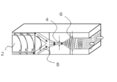
- FIG. 1 is a conceptual diagram for explaining the manufacturing method of the heat conductive resin sheet of the present embodiment, and shows a schematic cross-sectional view of a tip portion of an extruder and a T die.
- the T-die of the extruder has at least one of a first gap in a continuous vertical gap X, a second gap in a vertical gap Y, and an upper and lower side surface of a flow path between the first gap and the second gap. Have an inclined surface.
- the resin composition containing the thermally conductive filler is stirred and kneaded by the screw 2 and introduced into the first gap 4 (gap X) along the flow path 8.
- the flow of the resin composition is squeezed in the vertical direction (thickness direction) with respect to the flow direction in the extruder by the first gap 4 to form a thin strip shape.
- a shearing force acts on the resin composition, and the thermally conductive filler mixed in the resin is oriented in the flow direction of the resin composition.
- the heat conductive filler is oriented in the surface direction of the heat conductive resin sheet precursor.
- the gap of the first gap 4 may be adjusted as appropriate, for example, 0.5 mm or more and 5.0 mm or less.
- the gap of the first gap 4 is smaller than 0.5 mm, not only the extrusion pressure rises unnecessarily but also the resin composition is clogged.
- the gap of the first gap 4 is larger than 5.0 mm, the degree of orientation of the heat conductive filler with respect to the surface direction of the heat conductive resin sheet precursor is reduced.
- the cross-sectional area of the flow path 8 is increased, and the length in the vertical direction is increased. Therefore, the flow of the resin molded product precursor changes in the vertical direction. Subsequently, the resin sheet precursor is folded in a direction substantially perpendicular to the direction of the flow in the first gap 4 on the downstream side of the first gap 4 (in the flow path having the inclined surface), thereby forming a belt-shaped resin.
- the molded product precursor is mixed and fused, and is continuously extruded from the tip of the second gap 6 in a converged and integrated state, whereby the thermally conductive resin molded product (block-shaped product) of the present invention is obtained.
- the heat conductive filler is oriented in a substantially thickness direction of the heat conductive resin molded product (block-shaped product).
- thermally conductive molded product (block-like product) subjected to the crosslinking treatment is sliced in a direction perpendicular to the orientation direction of the thermally conductive filler to obtain a uniform thickness.
- a thermally conductive resin molded product (sheet) is manufactured.
- the gap Y of the second gap 6 is preferably not less than 2 times and not more than 40 times the gap X of the first gap 4.
- the upper and lower side surfaces of the flow path between the first gap 4 and the second gap 6 are inclined surfaces so that the pressure loss is small, and the thermally conductive filler is efficiently used in the thickness direction of the resin sheet. It is desirable to adjust the tilt angle for orientation.
- the inclination angle can be, for example, 10 ° to 50 °, and more preferably 20 ° to 30 °.
- the resin constituting the thermally conductive resin molded product of the present embodiment functions as a matrix or a binder.
- silicone resin silicone rubber and silicone gel
- urethane rubber acrylic rubber, butyl rubber, An ethylene propylene copolymer, an ethylene vinyl acetate copolymer, etc.
- silicone resins are particularly suitable because they are excellent in flexibility, shape followability, adhesion to a heat generating surface when brought into contact with an electronic component, and heat resistance.
- Silicone resins include silicone gels and silicone rubbers, which are roughly classified according to the number of crosslinking points being small / large or the difference in crosslinking species (addition reaction: platinum-based catalyst, condensation reaction: peroxide).
- Examples of the silicone rubber include millable silicone and addition reaction silicone.
- Silicone gel is more preferred because it has fewer crosslinking points and can be filled with more thermally conductive filler into silicone rubber. Note that silicone rubber is superior from the viewpoint of excellent heat resistance and electrical insulation due to a small number of crosslinking points.
- thermally conductive filler including the first thermally conductive filler and the second thermally conductive filler
- various conventionally known materials can be used as long as the effects of the present invention are not impaired.
- boron nitride (BN) graphite
- carbon fiber mica, alumina, aluminum nitride
- Silicon carbide silica, zinc oxide, magnesium oxide, calcium carbonate, magnesium carbonate, molybdenum disulfide, copper, aluminum and the like.
- the shape of the thermally conductive filler is not particularly limited and may be appropriately selected depending on the intended purpose.For example, scale-like, plate-like, film-like, massive, cylindrical, prismatic, elliptical, flat shape, etc. Can be mentioned.
- the second thermally conductive filler having a small particle size is easily dispersed in the gap between the first thermally conductive filler having a large particle size to form a heat conduction path, and the first thermally conductive filler is easily oriented in the resin. From this viewpoint, it is preferable that the aspect ratio of the first thermally conductive filler is 10 or more.
- the thermal conductivity of the second thermal conductive filler with a small particle size is achieved.
- the rate is preferably greater than 5 W / mK.
- the upper limit of the thermal conductivity ⁇ of the second thermal conductive filler may be 200 W / mK.
- the thermal conductivity is measured by a method called a laser flash method.
- Examples of the material used for the second thermally conductive filler include boron nitride (BN), aluminum nitride, silicon carbide, alumina, magnesium oxide, magnesium carbonate, and calcium carbonate.
- the proportion of the thermally conductive filler can be 10 to 80% by volume, and is appropriately determined according to the required thermal conductivity and the like. be able to.
- the proportion of the heat conductive filler is less than 10% by volume, the heat conduction effect is reduced.
- the proportion of the heat conductive filler exceeds 80% by volume, the heat conductive resin sheet precursor is folded in a direction substantially perpendicular to the flow direction in the first gap when passing through the first gap. This causes a problem that it becomes difficult to fuse the resin.
- the volume of the composition as the precursor is 100% by volume
- the mixing ratio of the first heat conductive filler and the second heat conductive filler in the heat conductive filler does not impair the effects of the present invention. It can be determined appropriately within a range.
- the first heat conductive filler may be 40 to 60% by volume and the second heat conductive filler may be 2 to 20% by volume
- the thermally conductive resin molded article of the present invention includes a reinforcing agent, a filler, a softener, a crosslinking agent, a crosslinking accelerator, a crosslinking accelerator, an antiaging agent, an adhesive, in addition to the resin and the thermally conductive filler described above.
- General blending / additives such as an imparting agent, an antistatic agent, and a kneading adhesive can be arbitrarily selected.
- Example 1 In the formulation shown in Table 1, a crosslinking agent and a thermally conductive filler were kneaded with two rolls into the silicone resin component to obtain a ribbon sheet (composition as a precursor).
- silicone resin component “silicone rubber DY32 1005U” manufactured by Toray Dow Corning Co., Ltd., a flame retardant component and a plasticizer component are used, and as the heat conductive filler, “PT110” (plate-like boron nitride manufactured by Momentive) is used.
- Average particle size 45 ⁇ m) and “DAW-03” alumina, average particle size 3 ⁇ m) manufactured by Denka Co., Ltd. were used.
- crosslinking agent “RC-4” and “MR-53” manufactured by Toray Dow Corning Co., Ltd. are used, and as the flame retardant component, those containing a metal compound such as iron oxide are preferable, manufactured by Momentive. “ME-41F” and “XC87-905” were used.
- plasticizer component a silicone oil having the same skeleton as the silicone rubber and requiring a viscosity of 100 cs to 10,000 cs is preferable, and “KF-96-3000CS” manufactured by Shin-Etsu Chemical Co., Ltd. was used.
- the ribbon sheet obtained as described above was used in a short axis extruder for rubber shown in FIG. 1 by using a vertical alignment mold (die) having a first gap of 1 mm and a second gap of 10 mm.
- a 10 mm thick thermally conductive resin molded article (block-like product) in which plate-like boron nitride was oriented in the thickness direction was produced, and the block-like product was subjected to a crosslinking treatment at 170 ° C. for 30 minutes.
- the block-like product after the crosslinking treatment was sliced perpendicularly to the thickness direction to produce a thermally conductive resin molded product (sheet) 1 having a thickness of 500 ⁇ m.
- the above cut accuracy is evaluated by the ratio of the thermal resistance value at the measurement pressure of 500 kPa to the thermal resistance value at the time of 100 kPa (thermal resistance value at the time of 100 kPa measurement / thermal resistance value at the time of 500 kPa measurement) and less than 1.9
- the case of ⁇ the case of 1.9 or more and less than 2.3 was evaluated as ⁇ , and the case of 2.3 or more was evaluated as ⁇ .
- Table 1 The results are shown in Table 1.
- Example 2 >> Example 1 except that “XGP” (plate boron nitride, average particle size 35 ⁇ m) and “DAW-03” (alumina, average particle size 3 ⁇ m) manufactured by Denka Co., Ltd. were used as the thermally conductive filler. The heat conductive resin sheet 2 was produced and evaluated. The results are shown in Table 1.
- Example 3 Except that “SGPS” (bulk boron nitride, average particle size 12 ⁇ m) and “DAW-03” (alumina, average particle size 3 ⁇ m) manufactured by Denka Co., Ltd. were used as the heat conductive filler, the same as in Example 1. Thus, a heat conductive resin sheet 2 was produced and evaluated. The results are shown in Table 1.
- Example 4 Example 1 except that “XGP” (plate boron nitride, average particle size 35 ⁇ m) and “SGPS” (block boron nitride, average particle size 12 ⁇ m) manufactured by Denka Co., Ltd. were used as the thermally conductive filler.
- the heat conductive resin sheet 2 was produced and evaluated. The results are shown in Table 1.
- Example 5 “XGP” (plate boron nitride, average particle size 35 ⁇ m), “SGPS” (bulk boron nitride, average particle size 12 ⁇ m) and “DAW-03” (alumina, average particle size) manufactured by Denka Co., Ltd. as heat conductive fillers A thermally conductive resin sheet 2 was produced and evaluated in the same manner as in Example 1 except that 3 ⁇ m in diameter was used. The results are shown in Table 1.
- Example 1 A comparative heat conductive resin sheet 1 was prepared in the same manner as in Example 1 except that only “XGP” (plate-like boron nitride, average particle size 35 ⁇ m) manufactured by Denka Co., Ltd. was used as the heat conductive filler. Evaluation was performed. The results are shown in Table 1.
- Example 2 A comparative heat conductive resin sheet 2 was produced in the same manner as in Example 1 except that only “XGP” (plate-like boron nitride, average particle size 35 ⁇ m) manufactured by Denka Co., Ltd. was used as the heat conductive filler. Evaluation was performed. The results are shown in Table 1.
- Comparative Example 4 In the formulation shown in Table 1, the silicone resin component was kneaded with a crosslinking agent and a thermally conductive filler with two rolls to obtain a sheet having a thickness of 2 mm. Silicone rubber “DY32 1005U” manufactured by Toray Dow Corning Co., Ltd. as a silicone resin component, a flame retardant component and a plasticizer component, and “XGP” (plate boron nitride manufactured by Denka Co., Ltd.) as a thermally conductive filler Average particle size 35 ⁇ m) and “DAW-03” (alumina, average particle size 3 ⁇ m) were used. As the crosslinking agent, “RC-4” and “MR-53” manufactured by Toray Dow Corning Co., Ltd.
- the flame retardant component preferably contains a metal compound such as iron oxide.
- a metal compound such as iron oxide.
- ME-41F and “XC87-905” were used.
- the plasticizer component a silicone oil having the same skeleton as the silicone rubber and requiring a viscosity of 100 cs to 10,000 cs is preferable, and “KF-96-3000CS” manufactured by Shin-Etsu Chemical Co., Ltd. was used.
- Comparative Example 5 >> “XGP” manufactured by Denka Co., Ltd. (plate-like boron nitride, average particle size of 35 ⁇ m) and “Silicia 740” manufactured by Fuji Silysia Chemical Co., Ltd. (fine powder silica, average particle size of 5 ⁇ m) are used as thermally conductive fillers.
- a comparative heat conductive resin sheet 5 was produced and evaluated in the same manner as in Example 1 except for the above. The results are shown in Table 1.
- thermoly conductive resin sheet exhibiting a low thermal resistance value is obtained by reducing the internal thermal resistance by high filling and reducing the interfacial thermal resistance by improving cut accuracy.
Abstract
Description
樹脂と、第一熱伝導性フィラー及び前記第一熱伝導性フィラーより小さい粒径を有する第二熱伝導性フィラーを含む熱伝導性フィラーと、を含み、
前記第一熱伝導性フィラーが10以上のアスペクト比を有するとともに前記熱伝導性樹脂成形品の略厚み方向に配向しており、
前記樹脂がシリコーン樹脂、アクリルゴム又はフッ素ゴムであり、
前記第二熱伝導性フィラーが5W/mK超の熱伝導率を有すること、
を特徴とする熱伝導性樹脂成形品を提供する。
表1に記載の配合にて、シリコーン樹脂成分に架橋剤及び熱伝導性フィラーを2本ロールで練り込み、リボンシート(前駆体としての組成物)を得た。シリコーン樹脂成分としては、東レダウコーニング(株)製の「シリコーンゴムDY32 1005U」、難燃剤成分及び可塑剤成分を用い、熱伝導性フィラーとしては、Momenntive社製の「PT110」(板状窒化ホウ素、平均粒径45μm)及びデンカ(株)製の「DAW‐03」(アルミナ、平均粒径3μm)を用いた。また、架橋剤としては、東レダウコーング(株)製の「RC-4」及び「MR‐53」を用い、難燃剤成分としては、酸化鉄等の金属化合物を含有したものが好ましく、Momenntive社製の「ME-41F」及び「XC87‐905」を用いた。可塑剤成分としては、シリコーンゴムと同骨格を有し、100csから10000csの粘度を要するシリコーンオイルが好ましく、信越化学工業(株)製の「KF-96-3000CS」を用いた。
(1)熱抵抗
得られた熱伝導性樹脂シートの厚さ方向の熱抵抗をTIM TESTER1300を用いて2水準の測定圧力で計測し、計測された値を表1に示した。なお、当該測定は定常法にて米国規格ASTM D5470に準拠した。
(2)カット精度
上記のスライス加工時のカット精度は、熱抵抗値に影響を与える。カット精度が悪い場合は、接触界面の熱抵抗が増加し、それに伴い熱抵抗測定時の圧力依存性が強まる。例えば、低い圧力の場合は接触界面の熱抵抗が高いが、高い圧力の場合は、シートが圧縮されることにより接触界面の熱抵抗が小さくなる。
上述のカット精度を測定時圧力500kPa時の熱抵抗値と100kPa時の熱抵抗値との比(100kPa測定時の熱抵抗値/500kPa測定時の熱抵抗値)にて評価し、1.9未満の場合を〇、1.9以上2.3未満の場合を△、2.3以上の場合を×と評価した。結果を表1に示した。
熱伝導性フィラーとしてデンカ(株)製の「XGP」(板状窒化ホウ素、平均粒径35μm)及び「DAW‐03」(アルミナ、平均粒径3μm)を用いた以外は、実施例1と同様にして熱伝導性樹脂シート2を作製し、評価を行った。結果を表1に示した。
熱伝導性フィラーとしてデンカ(株)製の「SGPS」(塊状窒化ホウ素、平均粒径12μm)及び「DAW‐03」(アルミナ、平均粒径3μm)を用いた以外は、実施例1と同様にして熱伝導性樹脂シート2を作製し、評価を行った。結果を表1に示した。
熱伝導性フィラーとしてデンカ(株)製の「XGP」(板状窒化ホウ素、平均粒径35μm)及び「SGPS」(塊状窒化ホウ素、平均粒径12μm)を用いた以外は、実施例1と同様にして熱伝導性樹脂シート2を作製し、評価を行った。結果を表1に示した。
熱伝導性フィラーとしてデンカ(株)製の「XGP」(板状窒化ホウ素、平均粒径35μm)、「SGPS」(塊状窒化ホウ素、平均粒径12μm)及び「DAW‐03」(アルミナ、平均粒径3μm)を用いた以外は、実施例1と同様にして熱伝導性樹脂シート2を作製し、評価を行った。結果を表1に示した。
熱伝導性フィラーとしてデンカ(株)製の「XGP」(板状窒化ホウ素、平均粒径35μm)のみを用いた以外は、実施例1と同様にして比較熱伝導性樹脂シート1を作製し、評価を行った。結果を表1に示した。
熱伝導性フィラーとしてデンカ(株)製の「XGP」(板状窒化ホウ素、平均粒径35μm)のみを用いた以外は、実施例1と同様にして比較熱伝導性樹脂シート2を作製し、評価を行った。結果を表1に示した。
熱伝導性フィラーとしてデンカ(株)製の「HGP」(板状窒化ホウ素、平均粒径5μm)及びデンカ(株)製の「DAW‐03」(アルミナ、平均粒径3μm)を用いた以外は、実施例1と同様にして比較熱伝導性樹脂シート3を作製し、評価を行った。結果を表1に示した。
表1に記載の配合にて、シリコーン樹脂成分に架橋剤及び熱伝導性フィラーを2本ロールで練り込み、厚さ2mmのシートを得た。シリコーン樹脂成分として、東レダウコーニング(株)製のシリコーンゴム「DY32 1005U」、難燃剤成分及び可塑剤成分を用い、熱伝導性フィラーとしてデンカ(株)製の「XGP」(板状窒化ホウ素、平均粒径35μm)及び「DAW‐03」(アルミナ、平均粒径3μm)を用いた。架橋剤としては、東レダウコーング(株)製の「RC-4」及び「MR‐53」を用い、難燃剤成分としては、酸化鉄等の金属化合物を含有したものが好ましく、Momenntive社製の「ME-41F」及び「XC87‐905」を用いた。可塑剤成分としては、シリコーンゴムと同骨格を有し、100csから10000csの粘度を要するシリコーンオイルが好ましく、信越化学工業(株)製の「KF-96-3000CS」を用いた。
熱伝導性フィラーとしてデンカ(株)製の「XGP」(板状窒化ホウ素、平均粒径35μm)及び富士シリシア化学(株)製の「サイリシア740」(微粉末シリカ、平均粒径5μm)を用いた以外は実施例1と同様にして比較熱伝導性樹脂シート5を作製し、評価を行った。結果を表1に示した。

4・・・第一ギャップ、
6・・・第二ギャップ、
8・・・流路。
Claims (2)
- 樹脂と、第一熱伝導性フィラー及び前記第一熱伝導性フィラーより小さい粒径を有する第二熱伝導性フィラーを含む熱伝導性フィラーと、を含み、
前記第一熱伝導性フィラーが10以上のアスペクト比を有するとともに前記熱伝導性樹脂成形品の略厚み方向に配向しており、
前記樹脂がシリコーン樹脂、アクリルゴム又はフッ素ゴムであり、
前記第二熱伝導性フィラーが5W/mK超の熱伝導率を有すること、
を特徴とする熱伝導性樹脂成形品。 - 前記樹脂のウェルドラインが前記熱伝導性樹脂成型品の略厚み方向に形成されていること、
を特徴とする請求項1に記載の熱伝導性樹脂成形品。
Priority Applications (5)
| Application Number | Priority Date | Filing Date | Title |
|---|---|---|---|
| JP2017506948A JP6200119B1 (ja) | 2016-02-01 | 2017-01-31 | 熱伝導性樹脂成形品 |
| US16/074,335 US11441011B2 (en) | 2016-02-01 | 2017-01-31 | Thermally conductive molded resin article |
| EP17747393.1A EP3412733B1 (en) | 2016-02-01 | 2017-01-31 | Thermally conductive molded resin article |
| KR1020187025158A KR102659683B1 (ko) | 2016-02-01 | 2017-01-31 | 열전도성 수지 성형품 |
| CN201780007761.1A CN108495897B (zh) | 2016-02-01 | 2017-01-31 | 热传导性树脂成型品 |
Applications Claiming Priority (2)
| Application Number | Priority Date | Filing Date | Title |
|---|---|---|---|
| JP2016016956 | 2016-02-01 | ||
| JP2016-016956 | 2016-02-01 |
Publications (1)
| Publication Number | Publication Date |
|---|---|
| WO2017135237A1 true WO2017135237A1 (ja) | 2017-08-10 |
Family
ID=59499762
Family Applications (1)
| Application Number | Title | Priority Date | Filing Date |
|---|---|---|---|
| PCT/JP2017/003366 WO2017135237A1 (ja) | 2016-02-01 | 2017-01-31 | 熱伝導性樹脂成型品 |
Country Status (7)
| Country | Link |
|---|---|
| US (1) | US11441011B2 (ja) |
| EP (1) | EP3412733B1 (ja) |
| JP (1) | JP6200119B1 (ja) |
| KR (1) | KR102659683B1 (ja) |
| CN (1) | CN108495897B (ja) |
| TW (1) | TWI745346B (ja) |
| WO (1) | WO2017135237A1 (ja) |
Cited By (8)
| Publication number | Priority date | Publication date | Assignee | Title |
|---|---|---|---|---|
| WO2019026745A1 (ja) * | 2017-07-31 | 2019-02-07 | バンドー化学株式会社 | 熱伝導性樹脂成型品 |
| WO2019189626A1 (ja) * | 2018-03-30 | 2019-10-03 | バンドー化学株式会社 | 熱伝導性シート、熱伝導性シートの製造方法、及び、熱伝導性シートの使用方法 |
| JP2019210329A (ja) * | 2018-05-31 | 2019-12-12 | パナソニックIpマネジメント株式会社 | 樹脂組成物、絶縁シート及びプリント配線板 |
| JP2020045456A (ja) * | 2018-09-20 | 2020-03-26 | 株式会社豊田中央研究所 | 熱伝導性複合材料、熱伝導性複合材料フィルム及びそれらの製造方法 |
| WO2020149335A1 (ja) * | 2019-01-17 | 2020-07-23 | バンドー化学株式会社 | 熱伝導性シート |
| WO2021251494A1 (ja) * | 2020-06-12 | 2021-12-16 | デンカ株式会社 | 熱伝導性樹脂組成物及び放熱シート |
| JP2022064582A (ja) * | 2020-10-14 | 2022-04-26 | 矢崎総業株式会社 | 熱伝導シート、電子機器及び車載装置 |
| WO2023038052A1 (ja) * | 2021-09-07 | 2023-03-16 | マクセルクレハ株式会社 | 放熱材シート |
Families Citing this family (4)
| Publication number | Priority date | Publication date | Assignee | Title |
|---|---|---|---|---|
| KR102409025B1 (ko) * | 2019-08-19 | 2022-06-16 | 주식회사 엘지화학 | 수지 조성물 |
| EP4006089A4 (en) * | 2019-08-19 | 2022-08-31 | LG Chem, Ltd. | RESIN COMPOSITION |
| CN112341819B (zh) * | 2020-11-25 | 2022-08-02 | 德阳中碳新材料科技有限公司 | 一种绝缘型石墨烯导热垫片的制备方法 |
| CN114407330A (zh) * | 2022-01-26 | 2022-04-29 | 北京大学 | 一种热界面材料及其制备方法 |
Citations (9)
| Publication number | Priority date | Publication date | Assignee | Title |
|---|---|---|---|---|
| JPH03200397A (ja) * | 1989-12-27 | 1991-09-02 | Tokai Rubber Ind Ltd | 放熱シート |
| JPH05102355A (ja) | 1991-10-09 | 1993-04-23 | Tokai Rubber Ind Ltd | 異方性熱伝導シートおよびその製法 |
| JPH10298894A (ja) * | 1997-04-24 | 1998-11-10 | Oji Paper Co Ltd | 抄紙ワイヤーの摩耗を低減する方法 |
| JP2000344919A (ja) * | 1999-06-02 | 2000-12-12 | Denki Kagaku Kogyo Kk | 熱伝導性シリコーン成形体の製造方法 |
| JP2003174127A (ja) | 2001-12-04 | 2003-06-20 | Polymatech Co Ltd | 異方性伝熱シートおよびその製造方法 |
| JP2005232313A (ja) * | 2004-02-19 | 2005-09-02 | Mitsubishi Electric Corp | 熱伝導性樹脂シートおよびこれを用いたパワーモジュール |
| JP2009010296A (ja) * | 2007-06-29 | 2009-01-15 | Nitto Denko Corp | 熱伝導性接着フィルム及びその製造方法 |
| JP2011178894A (ja) * | 2010-03-01 | 2011-09-15 | Mitsubishi Electric Corp | 熱硬化性樹脂組成物、熱伝導性シート及びパワーモジュール |
| JP2013103375A (ja) * | 2011-11-11 | 2013-05-30 | Daicel Corp | 異方熱伝導性フィルム及びその製造方法並びに組電池 |
Family Cites Families (9)
| Publication number | Priority date | Publication date | Assignee | Title |
|---|---|---|---|---|
| US6756005B2 (en) * | 2001-08-24 | 2004-06-29 | Cool Shield, Inc. | Method for making a thermally conductive article having an integrated surface and articles produced therefrom |
| US7038009B2 (en) * | 2001-08-31 | 2006-05-02 | Cool Shield, Inc. | Thermally conductive elastomeric pad and method of manufacturing same |
| JP5290539B2 (ja) * | 2007-06-08 | 2013-09-18 | バンドー化学株式会社 | ゴム組成物、ゴム成形体、放熱シート及びその製造方法 |
| JP5882581B2 (ja) * | 2008-10-21 | 2016-03-09 | 日立化成株式会社 | 熱伝導シート、その製造方法及びこれを用いた放熱装置 |
| CN102971365B (zh) | 2010-06-17 | 2015-07-01 | 迪睿合电子材料有限公司 | 导热性片和其制造方法 |
| WO2012043794A1 (ja) * | 2010-09-30 | 2012-04-05 | 旭化成ケミカルズ株式会社 | 射出成形体 |
| JP6034562B2 (ja) | 2011-12-20 | 2016-11-30 | デクセリアルズ株式会社 | 熱伝導性シート及び熱伝導性シートの製造方法 |
| WO2013146700A1 (ja) * | 2012-03-30 | 2013-10-03 | 三菱瓦斯化学株式会社 | 樹脂組成物、プリプレグ及び積層板 |
| JP2015073067A (ja) * | 2013-09-06 | 2015-04-16 | バンドー化学株式会社 | 熱伝導性樹脂成形品 |
-
2017
- 2017-01-31 WO PCT/JP2017/003366 patent/WO2017135237A1/ja active Application Filing
- 2017-01-31 CN CN201780007761.1A patent/CN108495897B/zh active Active
- 2017-01-31 EP EP17747393.1A patent/EP3412733B1/en active Active
- 2017-01-31 JP JP2017506948A patent/JP6200119B1/ja active Active
- 2017-01-31 US US16/074,335 patent/US11441011B2/en active Active
- 2017-01-31 KR KR1020187025158A patent/KR102659683B1/ko active IP Right Grant
- 2017-02-02 TW TW106103412A patent/TWI745346B/zh active
Patent Citations (9)
| Publication number | Priority date | Publication date | Assignee | Title |
|---|---|---|---|---|
| JPH03200397A (ja) * | 1989-12-27 | 1991-09-02 | Tokai Rubber Ind Ltd | 放熱シート |
| JPH05102355A (ja) | 1991-10-09 | 1993-04-23 | Tokai Rubber Ind Ltd | 異方性熱伝導シートおよびその製法 |
| JPH10298894A (ja) * | 1997-04-24 | 1998-11-10 | Oji Paper Co Ltd | 抄紙ワイヤーの摩耗を低減する方法 |
| JP2000344919A (ja) * | 1999-06-02 | 2000-12-12 | Denki Kagaku Kogyo Kk | 熱伝導性シリコーン成形体の製造方法 |
| JP2003174127A (ja) | 2001-12-04 | 2003-06-20 | Polymatech Co Ltd | 異方性伝熱シートおよびその製造方法 |
| JP2005232313A (ja) * | 2004-02-19 | 2005-09-02 | Mitsubishi Electric Corp | 熱伝導性樹脂シートおよびこれを用いたパワーモジュール |
| JP2009010296A (ja) * | 2007-06-29 | 2009-01-15 | Nitto Denko Corp | 熱伝導性接着フィルム及びその製造方法 |
| JP2011178894A (ja) * | 2010-03-01 | 2011-09-15 | Mitsubishi Electric Corp | 熱硬化性樹脂組成物、熱伝導性シート及びパワーモジュール |
| JP2013103375A (ja) * | 2011-11-11 | 2013-05-30 | Daicel Corp | 異方熱伝導性フィルム及びその製造方法並びに組電池 |
Non-Patent Citations (1)
| Title |
|---|
| See also references of EP3412733A4 |
Cited By (13)
| Publication number | Priority date | Publication date | Assignee | Title |
|---|---|---|---|---|
| JP6490877B1 (ja) * | 2017-07-31 | 2019-03-27 | バンドー化学株式会社 | 熱伝導性樹脂成型品 |
| WO2019026745A1 (ja) * | 2017-07-31 | 2019-02-07 | バンドー化学株式会社 | 熱伝導性樹脂成型品 |
| WO2019189626A1 (ja) * | 2018-03-30 | 2019-10-03 | バンドー化学株式会社 | 熱伝導性シート、熱伝導性シートの製造方法、及び、熱伝導性シートの使用方法 |
| JPWO2019189626A1 (ja) * | 2018-03-30 | 2020-04-30 | バンドー化学株式会社 | 熱伝導性シート、熱伝導性シートの製造方法、及び、熱伝導性シートの使用方法 |
| JP7122622B2 (ja) | 2018-05-31 | 2022-08-22 | パナソニックIpマネジメント株式会社 | 樹脂組成物、絶縁シート及びプリント配線板 |
| JP2019210329A (ja) * | 2018-05-31 | 2019-12-12 | パナソニックIpマネジメント株式会社 | 樹脂組成物、絶縁シート及びプリント配線板 |
| JP2020045456A (ja) * | 2018-09-20 | 2020-03-26 | 株式会社豊田中央研究所 | 熱伝導性複合材料、熱伝導性複合材料フィルム及びそれらの製造方法 |
| JP7402410B2 (ja) | 2018-09-20 | 2023-12-21 | 株式会社豊田中央研究所 | 熱伝導性複合材料、熱伝導性複合材料フィルム及びそれらの製造方法 |
| WO2020149335A1 (ja) * | 2019-01-17 | 2020-07-23 | バンドー化学株式会社 | 熱伝導性シート |
| JP6754917B1 (ja) * | 2019-01-17 | 2020-09-16 | バンドー化学株式会社 | 熱伝導性シート |
| WO2021251494A1 (ja) * | 2020-06-12 | 2021-12-16 | デンカ株式会社 | 熱伝導性樹脂組成物及び放熱シート |
| JP2022064582A (ja) * | 2020-10-14 | 2022-04-26 | 矢崎総業株式会社 | 熱伝導シート、電子機器及び車載装置 |
| WO2023038052A1 (ja) * | 2021-09-07 | 2023-03-16 | マクセルクレハ株式会社 | 放熱材シート |
Also Published As
| Publication number | Publication date |
|---|---|
| JPWO2017135237A1 (ja) | 2018-02-08 |
| EP3412733B1 (en) | 2021-10-20 |
| JP6200119B1 (ja) | 2017-09-20 |
| US11441011B2 (en) | 2022-09-13 |
| EP3412733A4 (en) | 2019-10-09 |
| TW201741397A (zh) | 2017-12-01 |
| CN108495897A (zh) | 2018-09-04 |
| TWI745346B (zh) | 2021-11-11 |
| KR20180108768A (ko) | 2018-10-04 |
| CN108495897B (zh) | 2021-09-14 |
| EP3412733A1 (en) | 2018-12-12 |
| US20210163708A1 (en) | 2021-06-03 |
| KR102659683B1 (ko) | 2024-04-19 |
Similar Documents
| Publication | Publication Date | Title |
|---|---|---|
| JP6200119B1 (ja) | 熱伝導性樹脂成形品 | |
| JP6552572B2 (ja) | 熱伝導性樹脂成形品 | |
| CN106575644B (zh) | 热传导性树脂成形品 | |
| JP5322894B2 (ja) | 絶縁性熱伝導シートの製造方法、絶縁性熱伝導シート及び放熱部材 | |
| CN107871721A (zh) | 导热性片材及其制备方法、以及半导体装置 | |
| EP3549974B1 (en) | Thermally conductive sheet | |
| WO2018180997A1 (ja) | 熱伝導性シート | |
| TWI762688B (zh) | 熱傳導性樹脂成型品 | |
| JP7137365B2 (ja) | 熱伝導性シート |
Legal Events
| Date | Code | Title | Description |
|---|---|---|---|
| ENP | Entry into the national phase |
Ref document number: 2017506948 Country of ref document: JP Kind code of ref document: A |
|
| 121 | Ep: the epo has been informed by wipo that ep was designated in this application |
Ref document number: 17747393 Country of ref document: EP Kind code of ref document: A1 |
|
| NENP | Non-entry into the national phase |
Ref country code: DE |
|
| ENP | Entry into the national phase |
Ref document number: 20187025158 Country of ref document: KR Kind code of ref document: A |
|
| WWE | Wipo information: entry into national phase |
Ref document number: 2017747393 Country of ref document: EP |
|
| ENP | Entry into the national phase |
Ref document number: 2017747393 Country of ref document: EP Effective date: 20180903 |