WO2017126693A1 - Élément de stockage au lithium non aqueux - Google Patents
Élément de stockage au lithium non aqueux Download PDFInfo
- Publication number
- WO2017126693A1 WO2017126693A1 PCT/JP2017/002020 JP2017002020W WO2017126693A1 WO 2017126693 A1 WO2017126693 A1 WO 2017126693A1 JP 2017002020 W JP2017002020 W JP 2017002020W WO 2017126693 A1 WO2017126693 A1 WO 2017126693A1
- Authority
- WO
- WIPO (PCT)
- Prior art keywords
- active material
- positive electrode
- negative electrode
- lithium
- electrode active
- Prior art date
Links
Images
Classifications
-
- H—ELECTRICITY
- H01—ELECTRIC ELEMENTS
- H01G—CAPACITORS; CAPACITORS, RECTIFIERS, DETECTORS, SWITCHING DEVICES OR LIGHT-SENSITIVE DEVICES, OF THE ELECTROLYTIC TYPE
- H01G11/00—Hybrid capacitors, i.e. capacitors having different positive and negative electrodes; Electric double-layer [EDL] capacitors; Processes for the manufacture thereof or of parts thereof
- H01G11/04—Hybrid capacitors
- H01G11/06—Hybrid capacitors with one of the electrodes allowing ions to be reversibly doped thereinto, e.g. lithium ion capacitors [LIC]
-
- H—ELECTRICITY
- H01—ELECTRIC ELEMENTS
- H01G—CAPACITORS; CAPACITORS, RECTIFIERS, DETECTORS, SWITCHING DEVICES OR LIGHT-SENSITIVE DEVICES, OF THE ELECTROLYTIC TYPE
- H01G11/00—Hybrid capacitors, i.e. capacitors having different positive and negative electrodes; Electric double-layer [EDL] capacitors; Processes for the manufacture thereof or of parts thereof
- H01G11/84—Processes for the manufacture of hybrid or EDL capacitors, or components thereof
-
- H—ELECTRICITY
- H01—ELECTRIC ELEMENTS
- H01G—CAPACITORS; CAPACITORS, RECTIFIERS, DETECTORS, SWITCHING DEVICES OR LIGHT-SENSITIVE DEVICES, OF THE ELECTROLYTIC TYPE
- H01G11/00—Hybrid capacitors, i.e. capacitors having different positive and negative electrodes; Electric double-layer [EDL] capacitors; Processes for the manufacture thereof or of parts thereof
- H01G11/22—Electrodes
- H01G11/24—Electrodes characterised by structural features of the materials making up or comprised in the electrodes, e.g. form, surface area or porosity; characterised by the structural features of powders or particles used therefor
-
- H—ELECTRICITY
- H01—ELECTRIC ELEMENTS
- H01G—CAPACITORS; CAPACITORS, RECTIFIERS, DETECTORS, SWITCHING DEVICES OR LIGHT-SENSITIVE DEVICES, OF THE ELECTROLYTIC TYPE
- H01G11/00—Hybrid capacitors, i.e. capacitors having different positive and negative electrodes; Electric double-layer [EDL] capacitors; Processes for the manufacture thereof or of parts thereof
- H01G11/22—Electrodes
- H01G11/30—Electrodes characterised by their material
- H01G11/32—Carbon-based
- H01G11/34—Carbon-based characterised by carbonisation or activation of carbon
-
- H—ELECTRICITY
- H01—ELECTRIC ELEMENTS
- H01G—CAPACITORS; CAPACITORS, RECTIFIERS, DETECTORS, SWITCHING DEVICES OR LIGHT-SENSITIVE DEVICES, OF THE ELECTROLYTIC TYPE
- H01G11/00—Hybrid capacitors, i.e. capacitors having different positive and negative electrodes; Electric double-layer [EDL] capacitors; Processes for the manufacture thereof or of parts thereof
- H01G11/22—Electrodes
- H01G11/30—Electrodes characterised by their material
- H01G11/50—Electrodes characterised by their material specially adapted for lithium-ion capacitors, e.g. for lithium-doping or for intercalation
-
- H—ELECTRICITY
- H01—ELECTRIC ELEMENTS
- H01G—CAPACITORS; CAPACITORS, RECTIFIERS, DETECTORS, SWITCHING DEVICES OR LIGHT-SENSITIVE DEVICES, OF THE ELECTROLYTIC TYPE
- H01G11/00—Hybrid capacitors, i.e. capacitors having different positive and negative electrodes; Electric double-layer [EDL] capacitors; Processes for the manufacture thereof or of parts thereof
- H01G11/66—Current collectors
- H01G11/70—Current collectors characterised by their structure
-
- H—ELECTRICITY
- H01—ELECTRIC ELEMENTS
- H01G—CAPACITORS; CAPACITORS, RECTIFIERS, DETECTORS, SWITCHING DEVICES OR LIGHT-SENSITIVE DEVICES, OF THE ELECTROLYTIC TYPE
- H01G11/00—Hybrid capacitors, i.e. capacitors having different positive and negative electrodes; Electric double-layer [EDL] capacitors; Processes for the manufacture thereof or of parts thereof
- H01G11/78—Cases; Housings; Encapsulations; Mountings
-
- H—ELECTRICITY
- H01—ELECTRIC ELEMENTS
- H01M—PROCESSES OR MEANS, e.g. BATTERIES, FOR THE DIRECT CONVERSION OF CHEMICAL ENERGY INTO ELECTRICAL ENERGY
- H01M10/00—Secondary cells; Manufacture thereof
- H01M10/05—Accumulators with non-aqueous electrolyte
- H01M10/052—Li-accumulators
-
- H—ELECTRICITY
- H01—ELECTRIC ELEMENTS
- H01M—PROCESSES OR MEANS, e.g. BATTERIES, FOR THE DIRECT CONVERSION OF CHEMICAL ENERGY INTO ELECTRICAL ENERGY
- H01M10/00—Secondary cells; Manufacture thereof
- H01M10/05—Accumulators with non-aqueous electrolyte
- H01M10/052—Li-accumulators
- H01M10/0525—Rocking-chair batteries, i.e. batteries with lithium insertion or intercalation in both electrodes; Lithium-ion batteries
-
- H—ELECTRICITY
- H01—ELECTRIC ELEMENTS
- H01M—PROCESSES OR MEANS, e.g. BATTERIES, FOR THE DIRECT CONVERSION OF CHEMICAL ENERGY INTO ELECTRICAL ENERGY
- H01M10/00—Secondary cells; Manufacture thereof
- H01M10/05—Accumulators with non-aqueous electrolyte
- H01M10/056—Accumulators with non-aqueous electrolyte characterised by the materials used as electrolytes, e.g. mixed inorganic/organic electrolytes
- H01M10/0564—Accumulators with non-aqueous electrolyte characterised by the materials used as electrolytes, e.g. mixed inorganic/organic electrolytes the electrolyte being constituted of organic materials only
- H01M10/0566—Liquid materials
- H01M10/0567—Liquid materials characterised by the additives
-
- H—ELECTRICITY
- H01—ELECTRIC ELEMENTS
- H01M—PROCESSES OR MEANS, e.g. BATTERIES, FOR THE DIRECT CONVERSION OF CHEMICAL ENERGY INTO ELECTRICAL ENERGY
- H01M10/00—Secondary cells; Manufacture thereof
- H01M10/05—Accumulators with non-aqueous electrolyte
- H01M10/058—Construction or manufacture
-
- H—ELECTRICITY
- H01—ELECTRIC ELEMENTS
- H01M—PROCESSES OR MEANS, e.g. BATTERIES, FOR THE DIRECT CONVERSION OF CHEMICAL ENERGY INTO ELECTRICAL ENERGY
- H01M10/00—Secondary cells; Manufacture thereof
- H01M10/05—Accumulators with non-aqueous electrolyte
- H01M10/058—Construction or manufacture
- H01M10/0585—Construction or manufacture of accumulators having only flat construction elements, i.e. flat positive electrodes, flat negative electrodes and flat separators
-
- H—ELECTRICITY
- H01—ELECTRIC ELEMENTS
- H01M—PROCESSES OR MEANS, e.g. BATTERIES, FOR THE DIRECT CONVERSION OF CHEMICAL ENERGY INTO ELECTRICAL ENERGY
- H01M10/00—Secondary cells; Manufacture thereof
- H01M10/42—Methods or arrangements for servicing or maintenance of secondary cells or secondary half-cells
- H01M10/44—Methods for charging or discharging
- H01M10/446—Initial charging measures
-
- H—ELECTRICITY
- H01—ELECTRIC ELEMENTS
- H01M—PROCESSES OR MEANS, e.g. BATTERIES, FOR THE DIRECT CONVERSION OF CHEMICAL ENERGY INTO ELECTRICAL ENERGY
- H01M4/00—Electrodes
- H01M4/02—Electrodes composed of, or comprising, active material
- H01M4/13—Electrodes for accumulators with non-aqueous electrolyte, e.g. for lithium-accumulators; Processes of manufacture thereof
- H01M4/133—Electrodes based on carbonaceous material, e.g. graphite-intercalation compounds or CFx
-
- H—ELECTRICITY
- H01—ELECTRIC ELEMENTS
- H01M—PROCESSES OR MEANS, e.g. BATTERIES, FOR THE DIRECT CONVERSION OF CHEMICAL ENERGY INTO ELECTRICAL ENERGY
- H01M4/00—Electrodes
- H01M4/02—Electrodes composed of, or comprising, active material
- H01M4/13—Electrodes for accumulators with non-aqueous electrolyte, e.g. for lithium-accumulators; Processes of manufacture thereof
- H01M4/139—Processes of manufacture
- H01M4/1393—Processes of manufacture of electrodes based on carbonaceous material, e.g. graphite-intercalation compounds or CFx
-
- H—ELECTRICITY
- H01—ELECTRIC ELEMENTS
- H01M—PROCESSES OR MEANS, e.g. BATTERIES, FOR THE DIRECT CONVERSION OF CHEMICAL ENERGY INTO ELECTRICAL ENERGY
- H01M4/00—Electrodes
- H01M4/02—Electrodes composed of, or comprising, active material
- H01M4/36—Selection of substances as active materials, active masses, active liquids
- H01M4/362—Composites
- H01M4/364—Composites as mixtures
-
- H—ELECTRICITY
- H01—ELECTRIC ELEMENTS
- H01M—PROCESSES OR MEANS, e.g. BATTERIES, FOR THE DIRECT CONVERSION OF CHEMICAL ENERGY INTO ELECTRICAL ENERGY
- H01M4/00—Electrodes
- H01M4/02—Electrodes composed of, or comprising, active material
- H01M4/62—Selection of inactive substances as ingredients for active masses, e.g. binders, fillers
-
- H—ELECTRICITY
- H01—ELECTRIC ELEMENTS
- H01G—CAPACITORS; CAPACITORS, RECTIFIERS, DETECTORS, SWITCHING DEVICES OR LIGHT-SENSITIVE DEVICES, OF THE ELECTROLYTIC TYPE
- H01G11/00—Hybrid capacitors, i.e. capacitors having different positive and negative electrodes; Electric double-layer [EDL] capacitors; Processes for the manufacture thereof or of parts thereof
- H01G11/22—Electrodes
- H01G11/26—Electrodes characterised by their structure, e.g. multi-layered, porosity or surface features
-
- Y—GENERAL TAGGING OF NEW TECHNOLOGICAL DEVELOPMENTS; GENERAL TAGGING OF CROSS-SECTIONAL TECHNOLOGIES SPANNING OVER SEVERAL SECTIONS OF THE IPC; TECHNICAL SUBJECTS COVERED BY FORMER USPC CROSS-REFERENCE ART COLLECTIONS [XRACs] AND DIGESTS
- Y02—TECHNOLOGIES OR APPLICATIONS FOR MITIGATION OR ADAPTATION AGAINST CLIMATE CHANGE
- Y02E—REDUCTION OF GREENHOUSE GAS [GHG] EMISSIONS, RELATED TO ENERGY GENERATION, TRANSMISSION OR DISTRIBUTION
- Y02E60/00—Enabling technologies; Technologies with a potential or indirect contribution to GHG emissions mitigation
- Y02E60/13—Energy storage using capacitors
-
- Y—GENERAL TAGGING OF NEW TECHNOLOGICAL DEVELOPMENTS; GENERAL TAGGING OF CROSS-SECTIONAL TECHNOLOGIES SPANNING OVER SEVERAL SECTIONS OF THE IPC; TECHNICAL SUBJECTS COVERED BY FORMER USPC CROSS-REFERENCE ART COLLECTIONS [XRACs] AND DIGESTS
- Y02—TECHNOLOGIES OR APPLICATIONS FOR MITIGATION OR ADAPTATION AGAINST CLIMATE CHANGE
- Y02P—CLIMATE CHANGE MITIGATION TECHNOLOGIES IN THE PRODUCTION OR PROCESSING OF GOODS
- Y02P70/00—Climate change mitigation technologies in the production process for final industrial or consumer products
- Y02P70/50—Manufacturing or production processes characterised by the final manufactured product
-
- Y—GENERAL TAGGING OF NEW TECHNOLOGICAL DEVELOPMENTS; GENERAL TAGGING OF CROSS-SECTIONAL TECHNOLOGIES SPANNING OVER SEVERAL SECTIONS OF THE IPC; TECHNICAL SUBJECTS COVERED BY FORMER USPC CROSS-REFERENCE ART COLLECTIONS [XRACs] AND DIGESTS
- Y02—TECHNOLOGIES OR APPLICATIONS FOR MITIGATION OR ADAPTATION AGAINST CLIMATE CHANGE
- Y02T—CLIMATE CHANGE MITIGATION TECHNOLOGIES RELATED TO TRANSPORTATION
- Y02T10/00—Road transport of goods or passengers
- Y02T10/60—Other road transportation technologies with climate change mitigation effect
- Y02T10/70—Energy storage systems for electromobility, e.g. batteries
Definitions
- the present invention relates to a non-aqueous lithium storage element.
- the first requirement for batteries used in these power storage systems is high energy density.
- a high energy density battery capable of meeting such demands development of a lithium ion battery has been vigorously advanced.
- the second requirement is high output characteristics. For example, in a combination of a high-efficiency engine and a power storage system (for example, a hybrid electric vehicle) or a combination of a fuel cell and a power storage system (for example, a fuel cell electric vehicle), high output discharge characteristics in the power storage system are required during acceleration. Yes.
- electric double layer capacitors nickel metal hydride batteries, and the like have been developed as high-power storage devices.
- those using activated carbon as electrodes have output characteristics of about 0.5 to 1 kW / L.
- This electric double layer capacitor has high durability (cycle characteristics and high temperature storage characteristics), and has been considered as an optimum device in the field where the high output is required.
- the energy density is only about 1 to 5 Wh / L. Therefore, further improvement in energy density is necessary.
- nickel-metal hydride batteries currently used in hybrid electric vehicles have a high output equivalent to that of electric double layer capacitors and an energy density of about 160 Wh / L.
- research for increasing the energy density and output and further improving durability (particularly stability at high temperatures) has been energetically advanced.
- research for higher output is also being conducted in lithium ion batteries.
- a lithium ion battery has been developed that can obtain a high output exceeding 3 kW / L at a depth of discharge (a value indicating what percentage of the discharge capacity of the storage element is discharged) 50%.
- the energy density is 100 Wh / L or less, and the high energy density, which is the greatest feature of the lithium ion battery, is intentionally suppressed.
- the discharge depth is used in a range narrower than the range of 0 to 100%. Since the capacity that can actually be used is further reduced, research for further improving the durability is being actively pursued.
- a lithium ion capacitor is a kind of power storage element that uses a non-aqueous electrolyte containing a lithium salt (hereinafter also referred to as “non-aqueous lithium power storage element”).
- the electrode materials generally used for the above-mentioned power storage elements and their characteristics when using materials such as activated carbon for the electrode and performing charge / discharge by adsorption / desorption (non-Faraday reaction) of ions on the activated carbon surface, High output and high durability are realized, but the energy density is reduced (for example, 1 time).
- the electric double layer capacitor is characterized in that the positive and negative electrodes use activated carbon (energy density 1 time), and the positive and negative electrodes are charged and discharged by a non-Faraday reaction, resulting in high output and high durability.
- a lithium ion capacitor uses activated carbon (energy density 1 time) for the positive electrode and a carbon material (10 times energy density) for the negative electrode, and is charged and discharged by a non-Faraday reaction at the positive electrode and a Faraday reaction at the negative electrode. It is a novel asymmetric capacitor that combines the features of a multilayer capacitor and a lithium ion secondary battery.
- Patent Document 1 proposes a lithium ion secondary battery using a positive electrode containing lithium carbonate in the positive electrode and having a current interruption mechanism that operates in accordance with an increase in the internal pressure of the battery.
- Patent Document 2 proposes a lithium ion secondary battery in which a lithium composite oxide such as lithium manganate is used as a positive electrode, and lithium carbonate is contained in the positive electrode to suppress elution of manganese.
- Patent Document 3 proposes a method for recovering the capacity of a deteriorated power storage element by oxidizing various lithium compounds as oxides at the positive electrode.
- these methods there is a problem that resistance is increased due to inhibition of electron conduction between active material particles due to addition of a lithium compound, and energy density is lowered, and there is room for further improvement with regard to higher output and higher energy density. It was.
- the potential change of the positive electrode active material layer applied to the front and back surfaces of the non-porous positive electrode current collector is not taken into consideration, and further suppression of excessive decomposition of the lithium compound contained in the positive electrode active material layer is not considered. There was room for improvement.
- activated carbon is used as a positive electrode active material, and a lithium material is occluded in advance by a chemical method or an electrochemical method as a negative electrode active material in a carbon material that can be occluded and released in an ionized state.
- a power storage element using a carbonaceous material has been proposed.
- applications of lithium ion capacitors include, for example, railway, construction equipment, automobile power storage elements, and the like, and further improvements in high-load charge / discharge cycle characteristics are required in these applications.
- the negative electrode active material layer occludes / releases lithium ions, and repeats expansion / contraction. Charge / discharge cycle characteristics deteriorate.
- binders with high binding power have low swelling with respect to non-aqueous electrolytes, and increasing the amount of binders clogs the diffusion path of lithium ions in non-aqueous electrolytes, increasing the internal resistance. Therefore, the overvoltage during the high-load charge / discharge cycle increases, the increase in the coating or deposit due to the reductive decomposition of the non-aqueous electrolyte solution in the negative electrode active material layer becomes remarkable, and good high-load charge / discharge cycle characteristics are obtained. Was difficult.
- Patent Document 5 proposes a lithium ion capacitor having a small deviation in thickness of the electrode layers on the front and back surfaces.
- the electrode of Patent Document 5 no consideration is given to suppressing a resistance increase in a high-load charge / discharge cycle in a positive electrode containing a lithium compound and suppressing gas generation due to decomposition of the lithium compound under a high voltage. .
- the present invention has been made in view of the above situation. Therefore, the problem to be solved by the present invention is that it has a high output and high energy density, is excellent in high load charge / discharge cycle characteristics, is nonporous without lowering the electron conductivity in the positive electrode containing a lithium compound.
- the present inventors diligently studied to solve the above problems and repeated experiments. As a result, by securing the electron conductivity between the positive electrode active material by controlling the average particle diameter Y 1 having an average particle diameter of X 1 and the positive electrode active material of a lithium compound contained in the positive electrode, high output and high energy We found that it can be densified. The present invention has been made based on this finding.
- the present invention is as follows: [1] a positive electrode containing a lithium compound other than the active material, a negative electrode, a separator, a nonaqueous lithium battery elements consisting of a non-aqueous electrolyte containing lithium ions, an average particle diameter of the lithium compound when the X 1, 0.1 ⁇ m ⁇ X 1 ⁇ 10.0 ⁇ m, and when the average particle diameter of the positive electrode active material is Y 1 , 2.0 ⁇ m ⁇ Y 1 ⁇ 20.0 ⁇ m, X 1 ⁇ Y 1 , A non-aqueous lithium storage element in which the amount of the lithium compound contained therein is 1% by mass or more and 50% by mass or less.
- the non-aqueous lithium storage element according to any one of [1] to [4], wherein the amount of the lithium compound contained in the positive electrode is 2% by mass or more and 20% by mass or less.
- the negative electrode includes a non-porous negative electrode current collector and a negative electrode active material layer including a negative electrode active material provided on one or both surfaces of the negative electrode current collector,
- the negative electrode active material includes a carbon material capable of occluding and releasing lithium ions,
- At least one of the positive electrodes has a non-porous positive electrode current collector, and a positive electrode active material layer including a positive electrode active material provided on both surfaces of the positive electrode current collector, Wherein the basis weight of the positive electrode active material layer on one surface of the positive electrode (C y plane) and C y1 (g / m 2) , the other side of the basis weight of the positive electrode active material layer (C x plane) C x1 (g / m 2 ), C y1 / C x1 is 0.70
- the positive electrode includes a positive electrode current collector, and a positive electrode active material layer including the positive electrode active material provided on one or both surfaces of the positive electrode current collector,
- the negative electrode has a negative electrode current collector having no through holes, and first and second negative electrode active material layers including a negative electrode active material provided on both surfaces of the negative electrode current collector, Each of the first and second negative electrode active material layers occludes lithium ions,
- the solid 7 Li-NMR spectrum of the first negative electrode active material layer provided on the first surface of the negative electrode current collector is calculated from the peak area of ⁇ 20 ppm to 60 ppm, and the first that absorbs the lithium ions.
- the peak area in the spectrum range of ⁇ 40 ppm to 40 ppm obtained by measurement with a repetition waiting time of 10 seconds is a, and the repetition waiting time is 3,000 seconds.
- a BET specific surface area per unit volume of the first or second negative electrode active material layer is 20 m 2 / cc or more and 1,500 m 2 / cc or less.
- Lithium storage element [10] The nonaqueous lithium electricity storage device according to [7] or [8], wherein the BET specific surface area per unit volume of the first or second negative electrode active material layer is 1 m 2 / cc to 50 m 2 / cc. element. [11]
- the positive electrode active material is derived from V 1 (cc / g) mesopore volume derived from pores having a diameter of 20 to 500 mm calculated by the BJH method, and from pores having a diameter of less than 20 mm calculated by the MP method.
- the nonaqueous lithium storage element according to any one of [1] to [10], which is activated carbon having a surface area of 1,500 m 2 / g or more and 3,000 m 2 / g or less.
- the positive electrode active material is derived from V 1 (cc / g) mesopore amount derived from pores having a diameter of 20 to 500 mm calculated by the BJH method, and from pores having a diameter of less than 20 mm calculated by the MP method.
- the nonaqueous lithium storage element according to any one of [1] to [10], which is activated carbon having a surface area of 2,300 m 2 / g or more and 4,000 m 2 / g or less.
- the solid 7 Li-NMR spectrum of the first negative electrode active material layer provided on the first surface of the negative electrode current collector is calculated from the peak area of ⁇ 20 ppm to 60 ppm, and the first that absorbs the lithium ions.
- the amount of lithium per unit mass of 1 negative electrode active material layer and q 1 the first surface wherein a back surface of said provided second surface of the negative electrode current collector second anode active solid material layer 7 Li for -NMR spectra are calculated from the peak area of -20 ppm ⁇ 60 ppm, when the amount of lithium per unit mass of the second anode active material layer which occludes lithium ions was q 2, variation of q 1 and q 2
- the coefficient CV is 0.001 or more and 0.50 or less, and the nonaqueous lithium storage element is charged at an environmental temperature of 25 ° C., a cell voltage of 2.2 V to 3.8 V, and a rate of 300 C.
- the internal resistance after the 60,000 charge / discharge cycles is Rb ( ⁇ )
- the internal resistance before starting the charge / discharge cycle is Ra ( ⁇ ).
- the active material is applied to both surfaces of the non-porous positive electrode current collector of the positive electrode, A negative electrode active material capable of inserting and extracting lithium ions is applied to both surfaces of the non-porous negative electrode current collector of the negative electrode,
- the basis weight of the positive electrode active material layer on one surface (C x surface) of the positive electrode is C x1 (g / m 2 )
- the basis weight of the positive electrode active material layer on the other surface (C y surface) is C y1 (g / M 2 )
- C x1 / C y1 is 1.02 or more and 1.35 or less
- Anode active basis weight material layer and A y1 (g / m 2) the negative electrode active material layer of the other surface (A x plane) of the one surface of the negative electrode facing the C y plane (A y plane)
- the basis weight of A x1 (g / m 2 ) is A x1 / A y1 is 0.74 or more and 0.98 or less
- R 1 is an alkylene group having 1 to 4 carbon atoms or a halogenated alkylene group having 1 to 4 carbon atoms
- R 2 is hydrogen, an alkyl group having 1 to 10 carbon atoms, 10 mono- or polyhydroxyalkyl group, an alkenyl group, a mono- or polyhydroxy alkenyl group having 2 to 10 carbon atoms, a cycloalkyl group having 3 to 6 carbon atoms, or an aryl group having 2 to 10 carbon atoms
- X 1 And X 2 are each independently — (COO) n (where n is 0 or 1).
- R 1 is an alkylene group having 1 to 4 carbon atoms or a halogenated alkylene group having 1 to 4 carbon atoms
- R 2 and R 3 are independently hydrogen, 1 to 10 carbon atoms, Alkyl group, mono- or polyhydroxyalkyl group having 1 to 10 carbon atoms, alkenyl group having 2 to 10 carbon atoms, mono- or polyhydroxyalkenyl group having 2 to 10 carbon atoms, cycloalkyl group having 3 to 6 carbon atoms, or aryl
- X 1 and X 2 are each independently — (COO) n (where n is 0 or 1).
- ⁇ Including one or more compounds represented by: When the content of the compound represented by the formulas (1) to (3) per unit mass on the Cy plane is C y3 (mol / g), C y3 is 1.60 ⁇ 10 ⁇ 4 or more and 300 The nonaqueous lithium storage element according to any one of [14] to [16], which is ⁇ 10 ⁇ 4 or less. [18] When the content of the compounds represented by the formulas (1) to (3) contained in the A y plane is A y3 (mol / g), C y3 / A y3 is 0.2 or more. The nonaqueous lithium storage element according to [17], which is 20 or less.
- the non-aqueous lithium storage element according to any one of [1] to [12] and [14] to [18], wherein the lithium compound is lithium carbonate, lithium oxide, or lithium hydroxide.
- the area ratio of carbonate ion mapping is S x % and S y % in the imaging image obtained by micro Raman spectroscopy measurement of the C x plane and the C y plane, in which the lithium compound is lithium carbonate.
- S x and S y are each 1 or more and 40 or less, and S x / S y is 1.00 or more and 2.00 or less, according to any one of [14] to [19]
- Non-aqueous lithium storage element is any one of [14] to [19]
- the positive electrode active material contained in the positive electrode active material layer having the C x plane or the Cy plane has a mesopore amount derived from pores having a diameter of 20 mm or more and 500 mm or less calculated by the BJH method as V 1 (cc / g)
- V 1 (cc / g) When the amount of micropores derived from pores having a diameter of less than 20 mm calculated by the MP method is V 2 (cc / g), 0.3 ⁇ V 1 ⁇ 0.8 and 0.5 ⁇ V 2
- Any one of [14] to [20] which is activated carbon that satisfies ⁇ 1.0 and has a specific surface area measured by the BET method of 1,500 m 2 / g to 3,000 m 2 / g.
- the specific surface area measured by the BET method is 2,300 m 2 / g or more and 4,000 m 2 / g or less. Water-based lithium storage element.
- the lithium ion doping amount with respect to the negative electrode active material is 530 mAh / g or more and 2,500 mAh / g or less per unit mass of the negative electrode active material, [1] to [12], [14] to [14] 22] The nonaqueous lithium storage element according to any one of [22]. [24] The nonaqueous lithium storage element according to [23], wherein the negative electrode active material has a BET specific surface area of 100 m 2 / g or more and 1,500 m 2 / g or less.
- a doping amount of the lithium ion with respect to the negative electrode active material is 50 mAh / g or more and 700 mAh / g or less per unit mass of the negative electrode active material
- a power storage module including the non-aqueous lithium power storage element of [1] to [27].
- a power regeneration system including the nonaqueous lithium storage element according to [1] to [27] or the storage module according to [28].
- a power load leveling system including the non-aqueous lithium storage element of [1] to [27] or the storage module of [28].
- An uninterruptible power supply system including the nonaqueous lithium storage element of [1] to [27] or the storage module of [28].
- a non-contact power feeding system including the non-aqueous lithium electricity storage element of [1] to [27] or the electricity storage module of [28].
- An energy harvesting system including the nonaqueous lithium storage element of [1] to [27] or the storage module of [28].
- a power storage system including the nonaqueous lithium power storage element of [1] to [27] or the power storage module of [28].
- the present invention it is excellent in high-load charge / discharge cycle characteristics, has high output and high energy density, adjusts the potential change of the positive electrode active material layer applied to both surfaces of the non-porous positive electrode current collector, In a non-aqueous lithium storage element using a nonporous positive electrode current collector and a nonporous negative electrode current collector, suppressing gas generated by excessive decomposition of the lithium compound remaining in the positive electrode under high temperature and high voltage, It is possible to mitigate the uneven distribution of ions in the electrolytic solution in a high-load charge / discharge cycle, suppress an increase in resistance, and suppress the decomposition of the lithium compound in the positive electrode under a high voltage, thereby suppressing gas generation.
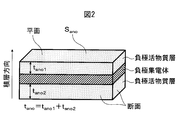
- FIG. 3 is a diagram showing a facing state of the positive electrode active material layer C x surface and the Cy surface and the negative electrode active material layer A x surface and the A y surface in the electrode laminate according to the fourth aspect of the present invention. .
- this embodiment an embodiment of the present invention (hereinafter referred to as “this embodiment”) will be described in detail, but the present invention is not limited to this embodiment.
- the upper limit value and the lower limit value in each numerical range of the present embodiment can be arbitrarily combined to constitute an arbitrary numerical range.
- a non-aqueous lithium storage element mainly includes a positive electrode, a negative electrode, a separator, an electrolytic solution, and an outer package.
- an organic solvent in which a lithium salt is dissolved hereinafter referred to as a non-aqueous electrolytic solution
- the non-aqueous lithium electricity storage device of the present invention comprises the following first to fourth aspects, and the aspects can be arbitrarily combined.
- the first aspect of the non-aqueous lithium electricity storage device of the present invention is Positive electrode comprises a lithium compound other than the active material, the average particle diameter of the lithium compound when the X 1, a 0.1 ⁇ m ⁇ X 1 ⁇ 10.0 ⁇ m, an average particle diameter of the positive electrode active material Y 1 When 2.0 ⁇ m ⁇ Y 1 ⁇ 20.0 ⁇ m, X 1 ⁇ Y 1 , and the amount of the lithium compound contained in the positive electrode is 1% by mass or more and 50% by mass or less, It is a non-aqueous lithium storage element.
- the second aspect of the present invention is The negative electrode has a non-porous negative electrode current collector and a negative electrode active material layer including a negative electrode active material provided on one or both surfaces of the negative electrode current collector,
- the negative electrode active material includes a carbon material capable of occluding and releasing lithium ions,
- At least one of the positive electrodes has a non-porous positive electrode current collector, and a positive electrode active material layer including a positive electrode active material provided on both surfaces of the positive electrode current collector,
- the basis weight of the positive electrode active material layer on one surface of the positive electrode (C y plane) and C y1 (g / m 2) , the other side of the basis weight of the positive electrode active material layer (C x plane) C x1 (g / m 2 ), C y1 / C x1 is 0.70 or more and 0.98 or less,
- the amount of lithium compound per unit area on the Cy plane is C y2 (g / m 2 ) and the amount of lithium compound
- the positive electrode has a positive electrode current collector and a positive electrode active material layer including the positive electrode active material provided on one or both surfaces of the positive electrode current collector
- the negative electrode has a negative electrode current collector having no through-holes, and first and second negative electrode active material layers including a negative electrode active material provided on both surfaces of the negative electrode current collector, Each of the first and second negative electrode active material layers occludes lithium ions
- the solid 7 Li-NMR spectrum of the first negative electrode active material layer provided on the first surface of the negative electrode current collector is calculated from the peak area of -20 ppm to 60 ppm, and the amount of lithium per unit mass of 1 negative electrode active material layer and q 1, and the second negative active solid material layer 7 provided on the second surface of the negative electrode current collector is a rear surface of the first surface
- the amount of lithium per unit mass of the second negative electrode active material layer occluded with the lithium ions calculated from the peak area of ⁇ 20 ppm to 60 ppm for
- the active material is applied to both surfaces of a non-porous positive electrode current collector in the positive electrode
- a negative electrode active material capable of inserting and extracting lithium ions is applied to both surfaces of a non-porous negative electrode current collector in the negative electrode
- the basis weight of the positive electrode active material layer on one surface (C x surface) of the positive electrode is C x1 (g / m 2 )
- the basis weight of the positive electrode active material layer on the other surface (C y surface) is C y1 (g / m 2 ).
- C x1 / C y1 is 1.02 or more and 1.35 or less
- embodiments of each aspect will be described in detail.
- FIG. 3 shows the facing state of the surface of the positive electrode active material layer and the surface of the negative electrode active material layer in the non-aqueous lithium electricity storage device according to the fourth embodiment of the present invention.
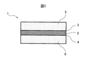
- the exterior body (15) of the non-aqueous lithium energy storage device according to the embodiment of the present invention houses an electrode laminate (14) formed by laminating a positive electrode and a negative electrode via a separator (13).
- the electrode laminate (14) at least one positive electrode includes a non-porous positive electrode current collector (9), and an active material is applied to both surfaces of the non-porous positive electrode current collector (9).
- the positive electrode active material layer having positive electrode active material layer C x plane (7), and a positive electrode active material layer having positive electrode active material layer C y plane (8) are arranged.
- At least one negative electrode includes a non-porous negative electrode current collector (12), and occludes and releases lithium ions on both sides of the non-porous negative electrode current collector (12).
- the negative electrode active material layer having a negative electrode active material layer a x surface (10), and a negative electrode active material layer having a negative electrode active material layer a y plane (11), respectively arranged Is done.
- the positive electrode active material layer C x surface (7) and the negative electrode active material layer A x surface (10) face each other with a separator (13) and / or the positive electrode active material layer C y.
- a single-sided positive electrode in which a positive electrode active material layer is formed only on one side of the positive electrode current collector or a double-sided positive electrode in which a positive electrode active material layer is formed on both sides of the positive electrode current collector may be formed on both sides of the single-sided negative electrode or the negative electrode current collector in which the negative electrode active material layer may be disposed only on one side of the negative electrode current collector
- the double-sided negative electrode may be arranged on the outermost side of the electrode laminate.
- the positive electrode of the present invention has a positive electrode current collector and a positive electrode active material layer present on one side or both sides thereof. Further, at least one of the positive electrodes in the second and fourth aspects of the present invention has a non-porous positive electrode current collector and a positive electrode active material layer including a positive electrode active material provided on both surfaces thereof. .
- non-porous positive electrode current collector means that lithium ions pass through the positive electrode current collector at least in the coated region of the positive electrode active material layer, and the lithium ions are uniform on the front and back surfaces of the positive electrode. It means a positive electrode current collector that does not have pores to the extent that it can be converted. Therefore, within the range where the effect of the present invention is exerted, the positive electrode current collector having a very small diameter or a small amount of holes and the positive electrode current collector having holes in a region where the positive electrode active material layer is not coated are also excluded. is not.
- the positive electrode in the present invention preferably contains a lithium compound as a positive electrode precursor before assembly of the storage element.
- the lithium compound is preferably contained in a positive electrode active material layer formed on the positive electrode current collector of the positive electrode precursor.
- the positive electrode state before a lithium dope process is defined as a positive electrode precursor
- the positive electrode state after a lithium dope process is defined as a positive electrode.
- the positive electrode active material layer preferably contains a positive electrode active material containing a carbon material.
- the positive electrode active material layer may contain optional components such as a conductive filler, a binder, and a dispersion stabilizer as necessary. Good.
- the positive electrode active material layer of the positive electrode precursor preferably contains a lithium compound.
- the positive electrode active material preferably contains a carbon material.
- a carbon material it is more preferable to use a carbon nanotube, a conductive polymer, or a porous carbon material, and more preferably activated carbon.
- One or more kinds of materials may be mixed and used for the positive electrode active material, and materials other than the carbon material (for example, a composite oxide of lithium and a transition metal) may be included.
- the content of the carbon material with respect to the total amount of the positive electrode active material is 50% by mass or more, more preferably 70% by mass or more.
- the content rate of the carbon material can be 100% by mass, it is preferably 90% by mass or less, for example, 80% by mass or less from the viewpoint of obtaining the effect of the combined use of other materials. Also good.
- activated carbon as a positive electrode active material
- the amount of mesopores derived from pores having a diameter of 20 to 500 mm calculated by the BJH method is V 1 (cc / g), and the amount of micropores derived from pores having a diameter of less than 20 mm calculated by the MP method.
- Is V 2 (cc / g) (1) For high input / output characteristics, 0.3 ⁇ V 1 ⁇ 0.8 and 0.5 ⁇ V 2 ⁇ 1.0 are satisfied, and the specific surface area measured by the BET method is 1, Activated carbon (hereinafter also referred to as activated carbon 1) having a mass of 500 m 2 / g to 3,000 m 2 / g is preferred. (2) In order to obtain a high energy density, 0.8 ⁇ V 1 ⁇ 2.5 and 0.8 ⁇ V 2 ⁇ 3.0 are satisfied, and the specific surface area measured by the BET method is 2, Activated carbon (hereinafter also referred to as activated carbon 2) of 300 m 2 / g to 4,000 m 2 / g is preferable.
- activated carbon 1 and the (2) activated carbon 2 will be described individually and sequentially.
- the mesopore amount V 1 of the activated carbon 1 is preferably a value larger than 0.3 cc / g from the viewpoint of increasing the input / output characteristics when the positive electrode material is incorporated in the storage element.
- V 1 is preferably 0.8 cc / g or less.
- V 1 is more preferably 0.35 cc / g or more and 0.7 cc / g or less, and further preferably 0.4 cc / g or more and 0.6 cc / g or less.
- the micropore amount V 2 of the activated carbon 1 is preferably 0.5 cc / g or more in order to increase the specific surface area of the activated carbon and increase the capacity.
- reducing the volume of the activated carbon increases the density of the electrode, from the viewpoint of increasing the capacity per unit volume, it is preferred that V 2 is not more than 1.0 cc / g.
- V 2 is more preferably 0.6 cc / g or more and 1.0 cc / g or less, and further preferably 0.8 cc / g or more and 1.0 cc / g or less.
- the ratio of meso Anaryou V 1 relative to the micropore volume V 2 (V 1 / V 2 ) is preferably in the range of 0.3 ⁇ V 1 / V 2 ⁇ 0.9. That is, V 1 / V 2 is 0.3 or more from the viewpoint of increasing the ratio of the mesopore amount to the micropore amount to such an extent that the decrease in output characteristics can be suppressed while maintaining a high capacity. It is preferable. On the other hand, V 1 / V 2 is 0.9 or less from the viewpoint of increasing the ratio of the micropore amount to the mesopore amount to such an extent that the decrease in capacity can be suppressed while maintaining high output characteristics. Is preferred.
- the average pore diameter of the activated carbon 1 is preferably 17 mm or more, more preferably 18 mm or more, and most preferably 20 mm or more from the viewpoint of maximizing the output of the obtained electricity storage device. Moreover, from the point of maximizing the capacity, the average pore diameter of the activated carbon 1 is preferably 25 mm or less.
- BET specific surface area of the activated carbon 1 is preferably from 1,500 m 2 / g or more 3,000 m 2 / g, more preferably not more than 1,500 m 2 / g or more 2,500 m 2 / g.
- the BET specific surface area is 1,500 m 2 / g or more, good energy density is easily obtained.
- the BET specific surface area is 3,000 m 2 / g or less, the strength of the electrode is maintained. Since there is no need to add a large amount of binder, the performance per electrode volume is increased.
- the activated carbon 1 having the above-described characteristics can be obtained using, for example, the raw materials and processing methods described below.
- the carbon source used as a raw material of the activated carbon 1 is not particularly limited.
- plant materials such as wood, wood flour, coconut husk, pulp by-products, bagasse, and molasses; peat, lignite, lignite, bituminous coal, anthracite, petroleum distillation residue components, petroleum pitch, coke, coal tar, etc.
- Fossil-based raw materials various synthetic resins such as phenol resin, vinyl chloride resin, vinyl acetate resin, melamine resin, urea resin, resorcinol resin, celluloid, epoxy resin, polyurethane resin, polyester resin, polyamide resin; polybutylene, polybutadiene, polychloroprene, etc.
- Synthetic rubber, other synthetic wood, synthetic pulp and the like, and carbides thereof are synththetic rubber, other synthetic wood, synthetic pulp and the like, and carbides thereof.
- plant raw materials such as coconut shells and wood flour, and their carbides are preferable, and coconut shell carbides are particularly preferable.
- a method of carbonization and activation for using these raw materials as the activated carbon known methods such as a fixed bed method, a moving bed method, a fluidized bed method, a slurry method, and a rotary kiln method can be employed.
- a carbonization method of these raw materials nitrogen, carbon dioxide, helium, argon, xenon, neon, carbon monoxide, an exhaust gas such as combustion exhaust gas, or other gases mainly composed of these inert gases.
- the method include baking using a mixed gas at about 400 to 700 ° C. (preferably 450 to 600 ° C.) for about 30 minutes to 10 hours.
- a gas activation method in which firing is performed using an activation gas such as water vapor, carbon dioxide, or oxygen is preferably used.
- a method using water vapor or carbon dioxide as the activation gas is preferable.
- the carbide is supplied for 3 to 12 hours (preferably 5 to 11) while supplying an activation gas at a rate of 0.5 to 3.0 kg / h (preferably 0.7 to 2.0 kg / h). It is preferable to activate by heating to 800 to 1,000 ° C. over a period of time, more preferably 6 to 10 hours. Furthermore, prior to the activation treatment of the carbide, the carbide may be activated in advance. In this primary activation, a method of gas activation by firing a carbon material at a temperature of less than 900 ° C. using an activation gas such as water vapor, carbon dioxide, oxygen or the like can be preferably employed.
- an activation gas such as water vapor, carbon dioxide, oxygen or the like
- the activated carbon 1 having the above-described characteristics that can be used in the present embodiment is manufactured. can do.
- the average particle diameter of the activated carbon 1 is preferably 2 to 20 ⁇ m.
- the average particle diameter is more preferably 2 to 15 ⁇ m, still more preferably 3 to 10 ⁇ m.
- the mesopore amount V 1 of the activated carbon 2 is preferably a value larger than 0.8 cc / g from the viewpoint of increasing the output characteristics when the positive electrode material is incorporated in the power storage element, while reducing the capacity of the power storage element. From the viewpoint of suppression, V 1 is preferably 2.5 cc / g or less. V 1 is more preferably 1.00 cc / g or more and 2.0 cc / g or less, and further preferably 1.2 cc / g or more and 1.8 cc / g or less.
- the micropore volume V 2 of the activated carbon 2 is preferably a value larger than 0.8 cc / g in order to increase the specific surface area of the activated carbon and increase the capacity, while increasing the density of the activated carbon as an electrode.
- V 2 is preferably 3.0 cc / g or less.
- V 2 is more preferably greater than 1.0 cc / g and not greater than 2.5 cc / g, and still more preferably not less than 1.5 cc / g and not greater than 2.5 cc / g.
- the activated carbon 2 having the above-described mesopore size and micropore size has a higher BET specific surface area than activated carbon used for conventional electric double layer capacitors or lithium ion capacitors.
- the specific value of the BET specific surface area of the activated carbon 2 is preferably 2,300 m 2 / g or more and 4,000 m 2 / g or less, and is 3,200 m 2 / g or more and 3,800 m 2 / g or less. It is more preferable.
- the BET specific surface area is 2,300 m 2 / g or more, a good energy density is easily obtained.
- the BET specific surface area is 4,000 m 2 / g or less, the strength of the electrode is maintained. Since there is no need to add a large amount of binder, the performance per electrode volume is increased.
- the activated carbon 2 having the above-described characteristics can be obtained using, for example, the raw materials and processing methods described below.
- the carbonaceous material used as a raw material for the activated carbon 2 is not particularly limited as long as it is a carbon source that is usually used as a raw material for activated carbon.
- plant-based raw materials such as wood, wood flour, and coconut shell
- Examples include fossil raw materials such as coke; various synthetic resins such as phenol resin, furan resin, vinyl chloride resin, vinyl acetate resin, melamine resin, urea resin, and resorcinol resin.
- a phenol resin and a furan resin are particularly preferable because they are suitable for producing activated carbon having a high specific surface area.
- Examples of the method for carbonizing these raw materials or the heating method during the activation treatment include known methods such as a fixed bed method, a moving bed method, a fluidized bed method, a slurry method, and a rotary kiln method.
- the atmosphere at the time of heating is an inert gas such as nitrogen, carbon dioxide, helium, or argon, or a gas mixed with other gases containing these inert gases as a main component.
- the carbonization temperature is about 400 to 700 ° C.
- the firing is performed for about 0.5 to 10 hours.
- Examples of the activation method of the carbide include a gas activation method in which firing is performed using an activation gas such as water vapor, carbon dioxide, and oxygen, and an alkali metal activation method in which heat treatment is performed after mixing with an alkali metal compound.
- An alkali metal activation method is preferable for producing activated carbon.
- the average particle diameter of the activated carbon 2 is preferably 2 ⁇ m or more and 20 ⁇ m or less.
- the average particle diameter of the activated carbon 2 is more preferably 3 ⁇ m or more and 10 ⁇ m or less.
- Each of the activated carbons 1 and 2 may be one type of activated carbon, or a mixture of two or more types of activated carbon, and each characteristic value described above may be shown as the entire mixture.
- the activated carbons 1 and 2 may be used by selecting any one of them, or may be used by mixing both.
- the positive electrode active material is a material other than activated carbon 1 and 2 (for example, activated carbon not having the specific V 1 and / or V 2 or a material other than activated carbon (for example, a composite oxide of lithium and transition metal). ) May be included.
- the content of the activated carbon 1, or the content of the activated carbon 2, or the total content of the activated carbons 1 and 2 is preferably more than 50% by mass of the total positive electrode active material, and 70% by mass or more. More preferably, it is more preferably 90% by mass or more, and most preferably 100% by mass.
- the content ratio of the positive electrode active material in the positive electrode active material layer is preferably 35% by mass or more and 95% by mass or less based on the total mass of the positive electrode active material layer in the positive electrode precursor.
- As an upper limit of the content rate of a positive electrode active material it is more preferable that it is 45 mass% or more, and it is further more preferable that it is 55 mass% or more.
- the content rate of a positive electrode active material it is more preferable that it is 90 mass% or less, and it is still more preferable that it is 85 mass% or less. By setting the content ratio in this range, suitable charge / discharge characteristics are exhibited.
- a lithium compound means a substance containing lithium, but excludes an active material involved in a Faraday reaction or a non-Faraday reaction in an electrode during charge / discharge of a storage element.
- the lithium compound in the present embodiment one type selected from lithium carbonate, lithium oxide, lithium hydroxide, lithium fluoride, lithium chloride, lithium oxalate, lithium iodide, lithium nitride, lithium oxalate, and lithium acetate.
- the above is preferably used.
- lithium carbonate, lithium oxide, and lithium hydroxide are more preferable, and lithium carbonate is more preferably used from the viewpoint that it can be handled in the air and has low hygroscopicity.
- Such a lithium compound is decomposed by the application of a voltage, functions as a lithium-doped dopant source for the negative electrode, and forms vacancies in the positive electrode active material layer, so that it has excellent electrolyte retention and ion conductivity. Can be formed.
- one or more alkali metal carbonates selected from sodium carbonate, potassium carbonate, rubidium carbonate, and cesium carbonate can also be used.
- the alkali metal carbonate can be used alone.
- the lithium compound contained in the positive electrode precursor may be one kind, may contain two or more kinds of lithium compounds, and may be used by mixing a lithium compound and another alkali metal carbonate.
- the positive electrode precursor of the present embodiment only needs to contain at least one lithium compound.
- M in the following formula is one or more selected from Na, K, Rb, and Cs.
- Oxides such as M 2 O, Hydroxides such as MOH, Halides such as MF and MCl, Oxalates such as M 2 (CO 2 ) 2
- One or more carboxylates such as RCOOM (wherein R is H, an alkyl group, or an aryl group) may be included.
- the positive electrode precursor BeCO 3, MgCO 3, CaCO 3, SrCO 3, or an alkaline earth metal carbonate selected from BaCO 3, as well as alkaline earth metal oxides, alkaline earth metal hydroxides, alkaline earth One or more metal halides, alkaline earth metal oxalates, and alkaline earth metal carboxylates may be included.
- a pulverizer such as a ball mill, a bead mill, a ring mill, a jet mill, or a rod mill can be used.
- the amount of the lithium compound contained in the positive electrode is preferably 1% by mass or more and 50% by mass or less.
- the lithium compound is 1% by mass or more, a sufficient amount of lithium carbonate that adsorbs the fluorine ions generated in the high load charge / discharge cycle is present, so that the high load charge / discharge cycle characteristics are improved. If the quantity of a lithium compound is 50 mass% or less, the energy density of a non-aqueous lithium electrical storage element can be raised.
- the content ratio of the lithium compound in the positive electrode active material layer is preferably 10% by mass or more and 60% by mass or less, and preferably 20% by mass or more and 50% by mass or less, based on the total mass of the positive electrode active material layer in the positive electrode precursor. More preferably.
- X 1 Average particle diameter of lithium compound and positive electrode active material
- the average particle diameter of the lithium compound and X 1 a 0.1 ⁇ m ⁇ X 1 ⁇ 10.0 ⁇ m
- the average particle diameter of the positive electrode active material Y 1 2.0 ⁇ m ⁇ Y 1 ⁇ 20.0 ⁇ m
- X 1 ⁇ Y 1 More preferably, the range of X 1 is 0.5 ⁇ m ⁇ X 1 ⁇ 5.0 ⁇ m, and 3.0 ⁇ m ⁇ Y 1 ⁇ 10.0 ⁇ m.
- X 1 When X 1 is more than 0.1 [mu] m, it is possible to leave the lithium carbonate in the positive electrode after lithium pre-doping, a high-load charge-discharge cycle characteristics by adsorbing the fluorine ions generated by the high-load charging and discharging cycle improves.
- X 1 is less than 10.0 [mu] m, since the reaction area with the fluorine ions generated by the high-load charging and discharging cycles increases, it is possible to efficiently adsorb the fluorine ions.
- Y 1 is not less than 2.0 .mu.m, it can be secured electronic conductivity between the positive electrode active material.
- Y 1 is less than 20.0 .mu.m, it can exhibit high output characteristics for reaction area with the electrolyte ions increases.
- X 1 ⁇ Y 1 the gap between the positive electrode active materials is filled with lithium carbonate, so that the energy density can be increased while ensuring the electron conductivity between the positive electrode active materials.
- the measurement method of X 1 and Y 1 is not particularly limited, but can be calculated from the SEM image of the positive electrode cross section and the SEM-EDX image.
- BIB processing can be used in which an Ar beam is irradiated from the upper part of the positive electrode and a smooth cross section is produced along the end of the shielding plate placed immediately above the sample.
- the distribution of carbonate ions can be obtained by measuring Raman imaging of the cross section of the positive electrode.
- the upper limit value and lower limit value of V 1 and the upper limit value and lower limit value of V 2 can be arbitrarily combined. In the present specification, the same applies to the combination of the upper limit value and the lower limit value of other constituent elements.
- the quantity of a lithium compound is 1 to 50 mass%.
- the preferred combination is 0.2 ⁇ m ⁇ X 1 ⁇ 7.0 ⁇ m, 5.0 ⁇ m ⁇ Y 1 ⁇ 15.0 ⁇ m, And the quantity of a lithium compound is 1 to 50 mass%.
- the preferred combination is 0.3 ⁇ m ⁇ X 1 ⁇ 10.0 ⁇ m, 5.0 ⁇ m ⁇ Y 1 ⁇ 15.0 ⁇ m, And the quantity of a lithium compound is 2 to 30 mass%.
- the preferred combination is 0.3 ⁇ m ⁇ X 1 ⁇ 5.0 ⁇ m, 5.0 ⁇ m ⁇ Y 1 ⁇ 15.0 ⁇ m, And the quantity of a lithium compound is 2 to 30 mass%.
- the preferred combination is 0.3 ⁇ m ⁇ X 1 ⁇ 10.0 ⁇ m, 5.0 ⁇ m ⁇ Y 1 ⁇ 15.0 ⁇ m, And the quantity of a lithium compound is 2 to 30 mass%.
- the lithium compound and the positive electrode active material can be distinguished from each other by oxygen mapping using a SEM-EDX image of the cross section of the positive electrode measured at an observation magnification of 1000 to 4000 times.
- the brightness and contrast are adjusted so that there is no pixel that reaches the maximum luminance value in the mapping image, and the average value of the luminance values is in the range of 40% to 60% of the maximum luminance value. Is preferred.
- a particle containing a bright portion binarized on the basis of the average value of brightness with an area of 50% or more is defined as a lithium compound.
- X 1 and Y 1 can be obtained by image analysis of an image obtained from the positive electrode cross section SEM-EDX measured in the same field of view as the positive electrode cross section SEM.
- the lithium compound particle X and other particles determined in the SEM image of the positive electrode cross section are the positive electrode active material particles Y, and the cross-sectional area of all the X and Y particles observed in the cross-sectional SEM image is as follows. S is obtained, and the particle diameter d calculated by the following formula is obtained. (The circumference ratio is ⁇ .) Using the obtained particle diameter d, volume average particle diameters X 0 and Y 0 are determined in the following formula.
- the lithium compound contained in the positive electrode is gradually decomposed and gasified when exposed to a high potential of about 4.0 V or more, and the generated gas inhibits diffusion of ions in the electrolyte. It will cause a rise. Therefore, it is preferable to form a film made of a fluorine-containing compound on the surface of the lithium compound to suppress the reaction of the lithium compound.
- the method for forming the coating film of the fluorine-containing compound is not particularly limited, but a fluorine-containing compound that decomposes at a high potential is contained in the electrolytic solution, and a high voltage equal to or higher than the decomposition potential of the fluorine-containing compound is applied to the non-aqueous lithium storage element. And a method of applying a temperature higher than the decomposition temperature.
- the coverage of the fluorine compound on the lithium compound surface is preferably 40% or more and 99% or less. When the coverage is 40% or more, decomposition of the lithium compound can be suppressed.
- the element mapping obtained by SEM-EDX on the positive electrode surface is obtained by calculating the area overlapping rate of fluorine mapping for the oxygen mapping binarized based on the average value of luminance values. It is done.
- the measurement conditions for elemental mapping of SEM-EDX are not particularly limited, but the number of pixels is preferably in the range of 128 ⁇ 128 pixels to 512 ⁇ 512 pixels, and there is no pixel that reaches the maximum luminance value in the mapping image, and the luminance value It is preferable to adjust the luminance and contrast so that the average value falls within the range of 40% to 60% of the maximum luminance value.
- the average value fluorine mapping area overlap ratio A 2 of for binarization oxygen mapped on the basis of the luminance values is 60% or less than 10%. If A 2 is 10% or more, it is possible to suppress the decomposition of the lithium compound. If A 2 is 60% or less, since a state of non-fluorinated to the inside of the lithium compound, it is possible to keep the positive electrode vicinity basic, excellent high-load cycle characteristics.
- the lithium compound contained in the positive electrode precursor can be oxidatively decomposed and reduced at the negative electrode, whereby the negative electrode can be pre-doped with lithium ions.
- a high voltage may be continuously applied for a long time.
- the electrolytic solution and the electrolyte are decomposed, and the resistance may increase. Therefore, in order to obtain a high-power non-aqueous lithium storage element, it is preferable to stop the application of a high voltage before the decomposition of the electrolytic solution and the electrolyte occurs to prevent the decomposition of the lithium compound.
- the positive electrode current collector is a non-porous positive electrode current collector, lithium ions cannot pass through the positive electrode current collector. It has been found that the potential of the positive electrode can be controlled by changing the basis weight of the active material layer. When the positive electrode current collector has holes to such an extent that lithium ions are made uniform on the front and back surfaces of the positive electrode through the holes, the above effect cannot be obtained.
- At least the positive electrode active material layer coated region of the positive electrode current collector is non-porous, and the positive electrode active material of the positive electrode current collector is coated.
- a surplus portion that is not formed may or may not have a hole.
- the basis weight of the positive electrode active material layer on one surface of the positive electrode (C y plane) and C y1 (g / m 2) , the basis weight of other positive electrode active material layer of one surface (C x plane) C x1 (g / m 2 ), C y1 / C x1 is 0.70 or more and 0.98 or less
- the amount of lithium compound per unit area of the Cy plane is C y2 (g / m 2 )
- the C x plane When the amount of lithium compound per unit area is C x2 (g / m 2 ), C y2 and C x2 are 0.10 or more and 20.0 or less, and C y2 / C x2 is 0.10 or more and 1.0.
- C y1 / C x1 is 0.70 or more, the use area of the negative electrode facing the C y plane and the C x plane is equivalent, and thus a high energy density can be realized.
- C y1 / C x1 is 0.98 or less, decomposition of the remaining lithium compound can be suppressed by changing the potential fluctuation range between the C y plane and the C x plane.
- C y2 and C x2 are preferably 0.10 or more and 20.0 or less. If Cy2 and Cx2 are 0.10 or more, it is excellent in high load charge / discharge cycle characteristics. If Cy2 and Cx2 are 20.0 or less, the energy density can be increased.
- C y2 / C x2 is preferably 0.10 or more and 1.0 or less.
- C y2 / C x2 is 0.10 or more, the electrolytic solution and the electrolyte are not easily decomposed, so that high output characteristics can be realized.
- C y2 / C x2 is 1.0 or less, decomposition of the lithium compound on the A-plane having a large potential fluctuation can be suppressed.
- the peak area in the spectrum range of ⁇ 40 ppm to 40 ppm obtained by measurement with a repetition waiting time of 10 seconds is set as a, and waiting for repetition. It is preferable that 1.04 ⁇ b / a ⁇ 5.56, where b is a peak area in a spectrum range of ⁇ 40 ppm to 40 ppm obtained by measurement for a time of 3,000 seconds.
- b / a is more preferably 1.05 ⁇ b / a ⁇ 3.79, further preferably 1.09 ⁇ b / a ⁇ 3.32, particularly preferably 1.14 ⁇ b / a ⁇ 2.86, Most preferably, 1.18 ⁇ b / a ⁇ 1.93.
- the lower limit and the upper limit can be any combination.
- the peak area a is considered to be a peak mainly derived from lithium ions occluded in the positive electrode active material or an attached lithium-containing film, and is considered to represent the amount of the positive electrode active material relatively.
- the peak area b is considered to be obtained by integrating the peaks derived from the lithium compound isolated from the positive electrode active material in addition to the peak area a. That is, the b / a is considered to represent the amount of the lithium compound isolated with respect to the positive electrode active material.
- the lithium compound isolated from the positive electrode active material can maintain high input / output characteristics without hindering electron conduction and ion diffusion between the positive electrode active materials.
- isolated means, for example, a state in which, when the positive electrode active material is an aggregate of activated carbon particles, lithium compound particles are isolated and dispersed therein. Means. If the b / a is 1.04 or more, the amount of the lithium compound relative to the positive electrode active material is sufficient, so that the lithium compound traps active products such as fluorine ions generated in the high load charge / discharge cycle. High load charge / discharge cycle characteristics are improved. On the other hand, if this b / a is 5.56 or less, the lithium compound can maintain high input / output characteristics without hindering electron conduction and ion diffusion between the positive electrode active materials.
- the peak area a in the spectrum range of ⁇ 40 ppm to 40 ppm when the repetition waiting time is 10 seconds and the repetition waiting time of 3,000 seconds The area ratio b / a with respect to the peak area b in the spectrum range of ⁇ 40 ppm to 40 ppm can be calculated by the following method.
- a commercially available apparatus can be used as an apparatus for measuring solid 7 Li-NMR. Under a room temperature environment, the measurement is performed by a single pulse method with a magic angle spinning speed of 14.5 kHz and an irradiation pulse width of 45 ° pulse.
- Measurement is performed for each of the case where the repetition waiting time is 10 seconds and the case where the repetition waiting time is 3,000 seconds, and a solid 7 Li-NMR spectrum is obtained.
- the measurement conditions other than the repetition waiting time that is, the number of integrations, the receiver gain, etc., are all made the same.
- a 1 mol / L lithium chloride aqueous solution is used as a shift reference, and the shift position separately measured as an external standard is 0 ppm.
- the sample is not rotated, and the irradiation pulse width is set to 45 ° pulse, and measurement is performed by a single pulse method. Peak areas a and b in the spectrum range of ⁇ 40 ppm to 40 ppm are obtained from the solid 7 Li-NMR spectrum of the positive electrode active material layer obtained by the above method, and b / a is calculated.
- the positive electrode active material layer in the present invention may contain optional components such as a conductive filler, a binder, and a dispersion stabilizer in addition to the positive electrode active material and the lithium compound as necessary.
- a conductive filler include a conductive carbonaceous material having higher conductivity than the positive electrode active material.
- a conductive filler for example, ketjen black, acetylene black, vapor-grown carbon fiber, graphite, carbon nanotube, and a mixture thereof are preferable.
- the mixing amount of the conductive filler in the positive electrode active material layer is preferably 0 to 20 parts by mass, and more preferably 1 to 15 parts by mass with respect to 100 parts by mass of the positive electrode active material.
- the conductive filler is preferably mixed from the viewpoint of high input. However, when the mixing amount is more than 20 parts by mass, the content ratio of the positive electrode active material in the positive electrode active material layer is decreased, so that the energy density per volume of the positive electrode active material layer is lowered, which is not preferable.
- the binder is not particularly limited. For example, PVdF (polyvinylidene fluoride), PTFE (polytetrafluoroethylene), polyimide, latex, styrene-butadiene copolymer, fluororubber, acrylic copolymer, etc. Can be used.
- the amount of the binder used is preferably 1 part by mass or more and 30 parts by mass or less with respect to 100 parts by mass of the positive electrode active material.
- the binder is 1% by mass or more, sufficient electrode strength is exhibited.
- the amount of the binder is 30 parts by mass or less, high input / output characteristics are exhibited without hindering the entry / exit and diffusion of ions to / from the positive electrode active material.
- limit especially as a dispersion stabilizer For example, PVP (polyvinyl pyrrolidone), PVA (polyvinyl alcohol), a cellulose derivative etc. can be used.
- the amount of the binder used is preferably 10 parts by mass or less with respect to 100 parts by mass of the positive electrode active material. When the amount of the dispersion stabilizer is 10 parts by mass or less, high input / output characteristics are exhibited without hindering the entry / exit and diffusion of ions to / from the positive electrode active material.
- the material constituting the positive electrode current collector in the present invention is not particularly limited as long as it is a material that has high electron conductivity and does not deteriorate due to elution into the electrolytic solution and reaction with the electrolyte or ions. Is preferred.
- an aluminum foil is particularly preferable.
- the metal foil may be a normal metal foil having no irregularities or through holes, or a metal foil having irregularities subjected to embossing, chemical etching, electrolytic deposition, blasting, etc., expanded metal, punching metal Alternatively, a metal foil having a through hole such as an etching foil may be used.
- the positive electrode current collector in the second and fourth aspects of the present invention is used as a normal metal foil having no irregularities or through holes, or “non-porous positive electrode current collector” defined above.
- a metal foil having unevenness subjected to embossing, chemical etching, electrolytic deposition, blasting, or the like, or a metal foil having through holes such as expanded metal, punching metal, etching foil or the like may be used.
- the thickness of the positive electrode current collector is not particularly limited as long as the shape and strength of the positive electrode can be sufficiently maintained, but for example, 1 to 100 ⁇ m is preferable.
- the positive electrode precursor serving as the positive electrode of the non-aqueous lithium storage element can be manufactured by an electrode manufacturing technique in a known lithium ion battery, electric double layer capacitor, or the like.
- a positive electrode active material, a lithium compound, and other optional components used as necessary are dispersed or dissolved in water or an organic solvent to prepare a slurry coating solution.
- a positive electrode precursor can be obtained by coating on one side or both sides of an electric conductor to form a coating film and drying it. Furthermore, you may press the obtained positive electrode precursor, and may adjust the film thickness and bulk density of a positive electrode active material layer.
- the positive electrode active material, the lithium compound, and other optional components to be used as needed are mixed in a dry method, and the resulting mixture is press-molded and then a conductive adhesive is used.
- a method of attaching to the positive electrode current collector is also possible.
- the positive electrode precursor coating solution is obtained by dry blending a part or all of various material powders including a positive electrode active material, and then water or an organic solvent, and / or a binder or a dispersion stabilizer is dissolved or dispersed therein. It may be prepared by adding a liquid or slurry substance. Alternatively, various material powders containing a positive electrode active material may be added to a liquid or slurry substance in which a binder or dispersion stabilizer is dissolved or dispersed in water or an organic solvent.
- a premixing is performed in which a positive electrode active material and a lithium compound, and a conductive filler as necessary are premixed using a ball mill or the like, and a conductive material is coated on a lithium compound having low conductivity. May be.
- a lithium compound becomes easy to decompose
- water is used as the solvent for the coating solution, the addition of a lithium compound may make the coating solution alkaline, so a pH adjuster may be added as necessary.
- the preparation of the positive electrode precursor coating solution is not particularly limited, but preferably a disperser such as a homodisper, a multiaxial disperser, a planetary mixer, a thin film swirl type high speed mixer, or the like can be used. .
- a disperser such as a homodisper, a multiaxial disperser, a planetary mixer, a thin film swirl type high speed mixer, or the like can be used.
- a peripheral speed of 1 m / s or more is preferable because various materials can be dissolved or dispersed well.
- a peripheral speed of 50 m / s or less is preferable because various materials are not destroyed by heat and shearing force due to dispersion and reaggregation does not occur.
- the particle size measured with a particle gauge is preferably 0.1 ⁇ m or more and 100 ⁇ m or less.
- the particle size is more preferably 80 ⁇ m or less, and further preferably the particle size is 50 ⁇ m or less.
- the particle size is 0.1 ⁇ m or less, the size is not more than the particle size of various material powders including the positive electrode active material, which is not preferable because the material is crushed during preparation of the coating liquid.
- the particle size is 100 ⁇ m or less, coating can be stably performed without clogging during coating liquid discharge or generation of streaks in the coating film.
- the viscosity ( ⁇ b) of the coating solution for the positive electrode precursor is preferably 1,000 mPa ⁇ s or more and 20,000 mPa ⁇ s or less.
- the viscosity ( ⁇ b) is more preferably 1,500 mPa ⁇ s to 10,000 mPa ⁇ s, and still more preferably 1,700 mPa ⁇ s to 5,000 mPa ⁇ s.
- the viscosity ( ⁇ b) is 1,000 mPa ⁇ s or more, dripping at the time of coating film formation is suppressed, and the coating film width and thickness can be controlled well.
- it is 20,000 mPa * s or less, it can apply stably with little pressure loss in the flow path of the coating liquid at the time of using a coating machine, and can control to below desired film thickness.
- the TI value (thixotropic index value) of the coating solution is preferably 1.1 or more.
- the TI value is more preferably 1.2 or more, and further preferably 1.5 or more.
- the coating film width and thickness can be favorably controlled.
- the formation of the coating film of the positive electrode precursor is not particularly limited, but preferably a coating machine such as a die coater, a comma coater, a knife coater, or a gravure coating machine can be used.
- the coating film may be formed by single layer coating or may be formed by multilayer coating. In the case of multilayer coating, the coating solution composition may be adjusted so that the lithium compound content in each layer of the coating film is different.
- the coating speed is preferably 0.1 m / min or more and 100 m / min or less.
- the coating speed is more preferably 0.5 m / min to 70 m / min, still more preferably 1 m / min to 50 m / min. If the coating speed is 0.1 m / min or more, stable coating can be achieved. On the other hand, if it is 100 m / min or less, sufficient coating accuracy can be secured.
- the drying of the coating film of the positive electrode precursor is not particularly limited, but a drying method such as hot air drying or infrared (IR) drying can be preferably used.
- the coating film may be dried at a single temperature, or may be dried at different temperatures. Moreover, you may dry combining several drying methods.
- the drying temperature is preferably 25 ° C. or higher and 200 ° C. or lower, more preferably 40 ° C. or higher and 180 ° C. or lower, and further preferably 50 ° C. or higher and 160 ° C. or lower. When the drying temperature is 25 ° C. or higher, the solvent in the coating film can be sufficiently volatilized.
- the press of the positive electrode precursor is not particularly limited, but preferably a press such as a hydraulic press or a vacuum press can be used.
- the film thickness, bulk density, and electrode strength of the positive electrode active material layer can be adjusted by the press pressure, gap, and surface temperature of the press part described later.
- the pressing pressure is preferably 0.5 kN / cm or more and 20 kN / cm or less, more preferably 1 kN / cm or more and 10 kN / cm or less, and further preferably 2 kN / cm or more and 7 kN / cm or less. If the pressing pressure is 0.5 kN / cm or more, the electrode strength can be sufficiently increased.
- the positive electrode precursor can be adjusted to the desired positive electrode active material layer film thickness and bulk density without bending or wrinkling.
- the clearance gap between press rolls can set arbitrary values according to the positive electrode precursor film thickness after drying so that it may become the film thickness and bulk density of a desired positive electrode active material layer.
- the press speed can be set to an arbitrary speed at which the positive electrode precursor does not bend or wrinkle.
- the surface temperature of a press part may be room temperature, and may be heated if necessary. The lower limit of the surface temperature of the press part in the case of heating is preferably the melting point minus 60 ° C. or more of the binder used, more preferably 45 ° C.
- the upper limit of the surface temperature of the press part in the case of heating is preferably the melting point of the binder used plus 50 ° C. or less, more preferably 30 ° C. or less, and further preferably 20 ° C. or less.
- PVdF polyvinylidene fluoride: melting point 150 ° C.
- it is preferably heated to 90 ° C. or higher and 200 ° C. or lower, more preferably 105 ° C. or higher and 180 ° C. or lower, and even more preferably 120 ° C. or higher. Heating to 170 ° C. or lower.
- a styrene-butadiene copolymer (melting point 100 ° C.) is used as the binder, it is preferably heated to 40 ° C. or higher and 150 ° C. or lower, more preferably 55 ° C. or higher and 130 ° C. or lower, and still more preferably 70 ° C. It is heating up to 120 ° C. or higher.
- the melting point of the binder can be determined at the endothermic peak position of DSC (Differential Scanning Calorimetry). For example, using a differential scanning calorimeter “DSC7” manufactured by PerkinElmer Co., Ltd., 10 mg of sample resin is set in a measurement cell, and the temperature is increased from 30 ° C. to 250 ° C. at a temperature increase rate of 10 ° C./min in a nitrogen gas atmosphere. The temperature is raised, and the endothermic peak temperature in the temperature raising process becomes the melting point. Moreover, you may press several times, changing the conditions of press pressure, a clearance gap, speed
- DSC7 Different Scanning Calorimetry
- the thickness of the positive electrode active material layer is preferably 20 ⁇ m or more and 200 ⁇ m or less per side of the positive electrode current collector.
- the thickness of the positive electrode active material layer is more preferably 25 ⁇ m or more and 100 ⁇ m or less, more preferably 30 ⁇ m or more and 80 ⁇ m or less per side. If this thickness is 20 ⁇ m or more, sufficient charge / discharge capacity can be exhibited. On the other hand, if this thickness is 200 ⁇ m or less, the ion diffusion resistance in the electrode can be kept low. As a result, sufficient output characteristics can be obtained, the cell volume can be reduced, and therefore the energy density can be increased. Note that the thickness of the positive electrode active material layer in the case where the current collector has through-holes and irregularities refers to the average value of the thickness per side of the portion of the current collector that does not have through-holes and irregularities.
- the bulk density of the positive electrode active material layer in the positive electrode after the lithium doping step described later is preferably 0.40 g / cm 3 or more, more preferably 0.50 g / cm 3 or more and 1.3 g / cm 3 or less. It is.
- the bulk density of the positive electrode active material layer is 0.40 g / cm 3 or more, a high energy density can be expressed, and miniaturization of the power storage element can be achieved.
- the bulk density is 1.3 g / cm 3 or less, the electrolyte solution is sufficiently diffused in the pores in the positive electrode active material layer, and high output characteristics are obtained.
- the BET specific surface area, mesopore amount, and micropore amount in the present embodiment are values obtained by the following methods, respectively.
- the sample is vacuum-dried at 200 ° C. all day and night, and adsorption and desorption isotherms are measured using nitrogen as an adsorbate.
- the BET specific surface area is determined by the BET multipoint method or the BET single point method, and the average pore diameter is obtained by dividing the total pore volume per mass by the BET specific surface area.
- the amount is calculated by the BJH method, and the amount of micropores is calculated by the MP method.
- the BJH method is a calculation method generally used for analysis of mesopores, and was proposed by Barrett, Joyner, Halenda et al. (Non-patent Document 1).
- MP method means a method for obtaining the micropore volume, micropore area, and micropore distribution using the “t-plot method” (Non-Patent Document 2).
- the average particle diameter in the present embodiment is the particle diameter at which the cumulative curve becomes 50% when the cumulative curve is determined with the total volume being 100% when the particle size distribution is measured using a particle size distribution measuring device. That is, it refers to a 50% diameter (Median diameter)).
- This average particle diameter can be measured using a commercially available laser diffraction particle size distribution analyzer.
- the negative electrode of the present invention has a negative electrode current collector and a negative electrode active material layer present on one side or both sides thereof.
- the negative electrode active material layer includes a negative electrode active material capable of inserting and extracting lithium ions.
- optional components such as a conductive filler, a binder, and a dispersion stabilizer may be included as necessary.
- non-porous negative electrode current collector means that lithium ions pass through the negative electrode current collector at least in the coated region of the negative electrode active material layer so that the lithium ions are uniform on the front and back surfaces of the negative electrode.
- the negative electrode current collector that does not have a hole to the extent that it can be converted. Therefore, within the range where the effect of the present invention is exerted, the negative electrode current collector having a very small diameter or a small amount of holes, or the negative electrode current collector having holes in a region where the negative electrode active material layer is not coated is also excluded. is not. Further, in the present embodiment, at least the region where the negative electrode active material layer is coated in the negative electrode current collector is non-porous, and the surplus portion where the negative electrode active material is not coated in the negative electrode current collector There may or may not be holes.
- the solid 7 Li-NMR spectrum of the first negative electrode active material layer provided on the first surface of the negative electrode current collector is calculated from a peak area of ⁇ 20 ppm to 60 ppm.
- the amount of lithium per unit mass of the first anode active material layer occludes ions and q 1
- the second anode active material layer provided on the first surface of the negative electrode current collector second surface of which is a back surface for solid 7 Li-NMR spectrum it is calculated from the peak area of -20 ppm ⁇ 60 ppm, when the amount of lithium per unit mass of the second anode active material layer obtained by inserting lithium ions was q 2, q 1 and q 2
- the coefficient of variation CV is 0.001 or more and 0.500 or less.
- the coefficient of variation CV is preferably 0.002 to 0.400, more preferably 0.004 to 0.300, still more preferably 0.008 to 0.250, and particularly preferably 0.010 to 0.200. It is as follows.
- the non-aqueous lithium electricity storage device uses a positive electrode containing a lithium compound other than the positive electrode active material, and a negative electrode having a coefficient of variation CV adjusted in the range of 0.001 to 0.500. Thus, it has high high load charge / discharge cycle characteristics.
- the principle is not clear and is not limited to theory, but it is presumed as follows. Since the magnitude of expansion / contraction of the negative electrode active material layer accompanying charge / discharge of the non-aqueous lithium storage element is proportional to the amount of lithium in the negative electrode active material layer, the first negative electrode active material on the first surface of the negative electrode current collector is used.
- the stress can be relieved by bending the negative electrode itself due to the expansion / contraction difference between the first negative electrode active material layer on the first surface and the second negative electrode active material layer on the second surface.
- the negative electrode active material layer can be prevented from peeling from the negative electrode current collector. Thereby, a high load charge / discharge cycle characteristic can be improved.
- the coefficient of variation CV When the coefficient of variation CV is 0.001 or more, the stress due to the expansion / contraction of the negative electrode active material layer accompanying the insertion / release of lithium ions can be relieved by the curvature of the negative electrode itself, and the negative electrode active material layer is peeled from the negative electrode current collector Therefore, a high load charge / discharge cycle characteristic can be exhibited.
- the coefficient of variation CV is 0.500 or less, peeling of the negative electrode active material layer from the negative electrode current collector caused by excessively large curvature of the negative electrode itself can be suppressed, and high high load charge / discharge cycle characteristics can be achieved. It is possible to suppress the bending of the non-aqueous lithium electricity storage element itself.
- the negative electrode active material layer formed is separated from the negative electrode active material layer formed on the back surface of the negative electrode current collector.
- FIG. 1 is a schematic side view of a negative electrode according to a third embodiment of the present invention.
- the first negative electrode active material layer (5) is formed on the first surface (3) of the negative electrode current collector (2), and the negative electrode current collector on the side opposite to the first surface is formed.
- a second negative electrode active material layer (6) is formed on the second surface (4) of the electric body (2), and the first negative electrode active material layer (5) and the second negative electrode active material layer (6) are separated from each other. is doing.
- the lithium amounts q 1 and q 2 obtained from the solid 7 Li-NMR spectrum of the negative electrode active material layer and the coefficient of variation CV thereof can be calculated by the following method.
- a commercially available apparatus can be used as an apparatus for measuring solid 7 Li-NMR. Under a room temperature environment, the measurement is performed by a single pulse method with a magic angle spinning speed of 14.5 kHz and an irradiation pulse width of 45 ° pulse. The measurement is set so that a sufficient waiting time is repeated between measurements.
- a 1 mol / L lithium chloride aqueous solution is used as a shift reference, and the shift position separately measured as an external standard is 0 ppm.
- the sample When measuring a 1 mol / L lithium chloride aqueous solution, the sample is not rotated, and the irradiation pulse width is set to 45 ° pulse, and measurement is performed by a single pulse method.
- the negative electrode active material is obtained by the above method.
- a solid 7 Li-NMR spectrum of the layer is obtained. With respect to the solid 7 Li-NMR spectrum of each obtained negative electrode active material layer, the peak area is determined for the components in the range of ⁇ 20 ppm to 60 ppm.
- the mass of the negative electrode active material layer is the mass of the negative electrode active material layer including lithium ions occluded in the negative electrode active material layer and / or a film or deposit contained in the negative electrode active material layer.
- the coefficient of variation CV is calculated by the following equation (3) using the obtained q 1 and q 2 . ⁇ Wherein m is the arithmetic mean of q 1 and q 2 and n is 2. ⁇
- the negative electrode active material layer contains a negative electrode active material, and may contain optional components such as a conductive filler, a binder, and a dispersion stabilizer as necessary.
- the negative electrode active material layer in the third aspect of the present invention includes first and second negative electrode active material layers formed on the front surface and the back surface of the negative electrode current collector, respectively, and in the first and second negative electrode active material layers The amounts of lithium (q 1 , q 2 ) are different from each other. As long as the first and second negative electrode active material layers each occlude lithium ions and the amounts of lithium (q 1 , q 2 ) are different from each other, a negative electrode active material, a negative electrode current collector, and It can be formed using a manufacturing method.
- the negative electrode active material a material capable of inserting and extracting lithium ions can be used. Specific examples include carbon materials, titanium oxide, silicon, silicon oxide, silicon alloys, silicon compounds, tin and tin compounds.
- the content of the carbon material with respect to the total amount of the negative electrode active material is 50% by mass or more, and more preferably 70% by mass or more.
- the content rate of the carbon material can be 100% by mass, it is preferably 90% by mass or less, for example, 80% by mass or less from the viewpoint of obtaining the effect of the combined use of other materials. Also good.
- the negative electrode active material is preferably doped with lithium ions.
- the lithium ion doped in the negative electrode active material mainly includes three forms.
- the first form is lithium ions that are previously occluded as a design value in the negative electrode active material before producing a non-aqueous lithium electricity storage device.
- the second form is lithium ions occluded in the negative electrode active material when a non-aqueous lithium electricity storage device is manufactured and shipped.
- a third form is lithium ions occluded in the negative electrode active material after using the non-aqueous lithium electricity storage device as a device.
- Examples of the carbon material include non-graphitizable carbon materials; graphitizable carbon materials; carbon black; carbon nanoparticles; activated carbon; artificial graphite; natural graphite; graphitized mesophase carbon spherules; Amorphous carbonaceous materials such as petroleum-based pitch, coal-based pitch, mesocarbon microbeads, coke, carbonaceous materials obtained by heat treatment of carbon precursors such as synthetic resins (for example, phenol resins); furfuryl alcohol Examples include thermal decomposition products of resins or novolac resins; fullerenes; carbon nanophones; and composite carbon materials thereof.
- a pitch composite carbon material that can be obtained by heat treatment in the state where one or more carbon materials and a petroleum-based pitch or a coal-based pitch coexist is preferable.
- the carbon material and the pitch may be mixed at a temperature higher than the melting point of the pitch.
- the heat treatment temperature may be a temperature at which a component generated by volatilization or thermal decomposition of the pitch used becomes a carbonaceous material.
- a non-oxidizing atmosphere is preferable.
- the pitch composite carbon material are pitch composite carbon materials 1a and 2a described later. Either of these may be selected and used, or both of them may be used in combination.
- the pitch composite carbon material 1a is obtained by heat treatment in a state where at least one carbon material having a BET specific surface area of 100 m 2 / g or more and 3000 m 2 / g or less and a petroleum-based pitch or a coal-based pitch coexist. Can do.
- the carbon material is not particularly limited, and activated carbon, carbon black, template porous carbon, high specific surface area graphite, carbon nanoparticles, and the like can be suitably used.
- the composite carbon material 1a is the composite carbon material using one or more carbon materials having a BET specific surface area of 50 m 2 / g or more and 3000 m 2 / g or less as the base material.
- the substrate is not particularly limited, and activated carbon, carbon black, template porous carbon, high specific surface area graphite, carbon nanoparticles, and the like can be suitably used.
- the BET specific surface area of the composite carbon material 1a is preferably 100 m 2 / g or more and 1,500 m 2 / g or less, more preferably 150 m 2 / g or more and 1,100 m. 2 / g or less, more preferably 180 m 2 / g or more and 550 m 2 / g or less. If the BET specific surface area of the composite carbon material 1a is 100 m 2 / g or more, the pores can be appropriately maintained, and the diffusion of lithium ions in the non-aqueous electrolyte solution is improved, so that high input / output characteristics are exhibited.
- the number of reaction sites with lithium ions in the non-aqueous electrolyte can be increased sufficiently, high input / output characteristics can be exhibited. Since the BET specific surface area of the composite carbon material 1a is 1,500 m 2 / g or less, the charge / discharge efficiency of lithium ions is improved, and excessive reductive decomposition of the non-aqueous electrolyte solution can be suppressed. Discharge cycle characteristics are less likely to be impaired.
- the BET specific surface area per unit volume of the negative electrode active material layer in the negative electrode active material layer using the composite carbon material 1a as the negative electrode active material is 20 m 2 / cc or more and 1,500 m 2 / It is preferable that it is cc or less.
- the BET specific surface area per unit volume of the negative electrode active material layer is more preferably 25 m 2 / cc to 1,000 m 2 / cc, further preferably 30 m 2 / cc to 500 m 2 / cc, particularly preferably 33 m 2. / Cc to 400 m 2 / cc.
- the BET specific surface area per unit volume of the negative electrode active material layer is 20 m 2 / cc or more, the number of reaction sites with lithium ions in the non-aqueous electrolyte solution can be sufficiently increased per unit volume of the negative electrode active material layer.
- a non-aqueous lithium storage element using the same can exhibit high input / output characteristics.
- the BET specific surface area per unit volume of the negative electrode active material layer is 1,500 m 2 / cc or less, excessive reductive decomposition of the non-aqueous electrolyte solution in the negative electrode active material layer can be suppressed.
- the non-aqueous lithium storage element can exhibit high high load charge / discharge cycle characteristics.
- the mass ratio of the carbonaceous material to the base material in the composite carbon material 1a is preferably 10% or more and 200% or less. This mass ratio is preferably 12% to 180%, more preferably 15% to 160%, and particularly preferably 18% to 150%. If the mass ratio of the carbonaceous material is 10% or more, the micropores of the base material can be appropriately filled with the carbonaceous material, and the charge / discharge efficiency of lithium ions is improved. Cycle durability can be shown. Further, if the mass ratio of the carbonaceous material is 200% or less, the pores can be appropriately maintained and the lithium ion diffusion becomes good, so that high input / output characteristics can be exhibited.
- the doping amount of lithium ions per unit mass of the composite carbon material 1a is preferably 530 mAh / g or more and 2500 mAh / g or less. More preferably, it is 620 mAh / g or more and 2,100 mAh / g or less, More preferably, it is 760 mAh / g or more and 1,700 mAh / g or less, Most preferably, it is 840 mAh / g or more and 1,500 mAh / g or less. Doping lithium ions lowers the negative electrode potential. Therefore, when the negative electrode including the composite carbon material 1a doped with lithium ions is combined with the positive electrode, the voltage of the non-aqueous lithium storage element is increased and the utilization capacity of the positive electrode is increased.
- the capacity and energy density of the obtained non-aqueous lithium storage element are increased.
- the doping amount is 530 mAh / g or more
- lithium ions are well doped into irreversible sites that cannot be desorbed once the lithium ions in the composite carbon material 1a are inserted, and further, the composite carbon material 1a with respect to a desired amount of lithium. Can be reduced. Therefore, the negative electrode film thickness can be reduced, and a high energy density can be obtained.
- the larger the doping amount the lower the negative electrode potential, and the input / output characteristics, energy density, and durability are improved.
- the doping amount is 2,500 mAh / g or less, there is no possibility that side effects such as precipitation of lithium metal occur.
- the composite carbon material 1a using activated carbon as the base material will be described.
- the amount of mesopores derived from pores having a diameter of 20 to 500 mm calculated by the BJH method is Vm1 (cc / g), and the amount of micropores derived from pores having a diameter of less than 20 mm calculated by the MP method.
- Is Vm2 (cc / g) it is preferable that 0.010 ⁇ Vm1 ⁇ 0.300 and 0.001 ⁇ Vm2 ⁇ 0.650.
- the mesopore amount Vm1 is more preferably 0.010 ⁇ Vm1 ⁇ 0.225, and further preferably 0.010 ⁇ Vm1 ⁇ 0.200.
- the micropore amount Vm2 is more preferably 0.001 ⁇ Vm2 ⁇ 0.200, further preferably 0.001 ⁇ Vm2 ⁇ 0.150, and particularly preferably 0.001 ⁇ Vm2 ⁇ 0.100.
- the mesopore amount Vm1 is 0.300 cc / g or less, the BET specific surface area can be increased, the lithium ion doping amount can be increased, and the bulk density of the negative electrode can be increased. As a result, the negative electrode can be thinned. Moreover, if the micropore amount Vm2 is 0.650 cc / g or less, high charge / discharge efficiency for lithium ions can be maintained. On the other hand, if the mesopore volume Vm1 and the micropore volume Vm2 are equal to or higher than the lower limit (0.010 ⁇ Vm1, 0.001 ⁇ Vm2), high input / output characteristics can be obtained.
- the average pore diameter of the composite carbon material 1a is preferably 20 mm or more, more preferably 25 mm or more, and further preferably 30 mm or more from the viewpoint of high input / output characteristics. On the other hand, from the viewpoint of high energy density, the average pore diameter is preferably 65 mm or less, more preferably 60 mm or less.
- the average particle size of the composite carbon material 1a is preferably 1 ⁇ m or more and 10 ⁇ m or less. About a lower limit, More preferably, it is 2 micrometers or more, More preferably, it is 2.5 micrometers or more. About an upper limit, More preferably, it is 6 micrometers or less, More preferably, it is 4 micrometers or less. If the average particle diameter is 1 ⁇ m or more and 10 ⁇ m or less, good durability is maintained.
- the hydrogen atom / carbon atom number ratio (H / C) of the composite carbon material 1a is preferably 0.05 or more and 0.35 or less, and more preferably 0.05 or more and 0.15 or less. .
- H / C is 0.35 or less, the structure (typically polycyclic aromatic conjugated structure) of the carbonaceous material deposited on the activated carbon surface is well developed and the capacity (energy Density) and charge / discharge efficiency are increased.
- H / C is 0.05 or more, since carbonization does not proceed excessively, a good energy density can be obtained.
- H / C is measured by an elemental analyzer.
- the composite carbon material 1a has an amorphous structure derived from the activated carbon of the base material, but at the same time has a crystal structure mainly derived from the deposited carbonaceous material.
- the composite carbon material A has a (002) plane spacing d002 of 3.60 mm to 4.00 mm, and a c-axis direction crystallite obtained from the half width of this peak.
- the size Lc is preferably 8.0 to 20.0 and d002 is 3.60 to 3.75 and the crystallite size Lc in the c-axis direction obtained from the half width of this peak is 11.
- the range of 0 to 16.0 is more preferable.
- the activated carbon used as the base material of the composite carbon material 1a is not particularly limited as long as the obtained composite carbon material 1a exhibits desired characteristics.
- commercially available products obtained from various raw materials such as petroleum-based, coal-based, plant-based, and polymer-based materials can be used.
- the average particle diameter is more preferably 2 ⁇ m or more and 10 ⁇ m or less.
- the pore distribution of the activated carbon used for the substrate is important.
- the amount of mesopores derived from pores having a diameter of 20 to 500 mm calculated by the BJH method is V1 (cc / g)
- the amount of micropores derived from pores having a diameter of less than 20 mm calculated by the MP method is used.
- V2 (cc / g) 0.050 ⁇ V1 ⁇ 0.500, 0.005 ⁇ V2 ⁇ 1.000, and 0.2 ⁇ V1 / V2 ⁇ 20.0 are preferable.
- the mesopore amount V1 is more preferably 0.050 ⁇ V1 ⁇ 0.350, and further preferably 0.100 ⁇ V1 ⁇ 0.300.
- the micropore amount V2 is more preferably 0.005 ⁇ V2 ⁇ 0.850, and further preferably 0.100 ⁇ V2 ⁇ 0.800.
- the ratio of mesopore amount / micropore amount is more preferably 0.22 ⁇ V1 / V2 ⁇ 15.0, and further preferably 0.25 ⁇ V1 / V2 ⁇ 10.0.
- the pore structure can be easily controlled.
- the mesopore amount V1 of the activated carbon is 0.050 or more
- the micropore amount V2 is 0.005 or more
- V1 / V2 is 0.2 or more
- V1 / V2 is 20.0.
- the structure can be easily obtained even in the following cases.
- the carbonaceous material precursor used as a raw material of the composite carbon material 1a is an organic material that can be dissolved in a solid, liquid, or solvent, which can deposit the carbonaceous material on activated carbon by heat treatment.
- the carbonaceous material precursor include pitch, mesocarbon microbeads, coke, and synthetic resin (for example, phenol resin).
- Pitch is roughly divided into petroleum pitch and coal pitch.
- petroleum pitches include crude oil distillation residue, fluid catalytic cracking residue (decant oil, etc.), bottom oil derived from thermal crackers, ethylene tar obtained during naphtha cracking, and the like.
- the pitch When the pitch is used, the pitch is heat-treated in the presence of activated carbon, and a carbonaceous material is deposited on the activated carbon by thermally reacting the volatile component or pyrolysis component of the pitch on the surface of the activated carbon. Material 1a is obtained.
- the deposition of pitch volatile components or pyrolysis components into the activated carbon pores proceeds at a temperature of about 200 to 500 ° C., and the reaction that the deposited components become carbonaceous materials proceeds at 400 ° C. or higher.
- the peak temperature (maximum temperature reached) during the heat treatment is appropriately determined depending on the characteristics of the composite carbon material 1a to be obtained, the thermal reaction pattern, the thermal reaction atmosphere, etc., but is preferably 400 ° C. or higher.
- the time for maintaining the peak temperature during the heat treatment is preferably 30 minutes to 10 hours, more preferably 1 hour to 7 hours, and further preferably 2 hours to 5 hours.
- the carbonaceous material deposited on the activated carbon surface is considered to be a polycyclic aromatic hydrocarbon. .
- the softening point of the pitch used is preferably 30 ° C. or higher and 250 ° C. or lower, and more preferably 60 ° C. or higher and 130 ° C. or lower.
- a pitch having a softening point of 30 ° C. or higher can be handled with high accuracy without any problem in handling properties.
- the pitch having a softening point of 250 ° C. or less contains a large amount of relatively low molecular weight compounds. Therefore, when the pitch is used, fine pores in the activated carbon can be deposited.
- activated carbon is heat-treated in an inert atmosphere containing hydrocarbon gas volatilized from a carbonaceous material precursor, and the carbonaceous material is coated in a gas phase.
- the method of making it wear is mentioned.
- a method in which activated carbon and a carbonaceous material precursor are mixed in advance and heat-treated, or a method in which a carbonaceous material precursor dissolved in a solvent is applied to activated carbon and dried is then heat-treated.
- the mass ratio of the carbonaceous material to the activated carbon in the composite carbon material 1a is 10% or more and 100% or less. This mass ratio is preferably 15% or more and 80% or less. If the mass ratio of the carbonaceous material is 10% or more, the micropores of the activated carbon can be appropriately filled with the carbonaceous material, and the charge / discharge efficiency of lithium ions is improved. Will not be damaged. Further, if the mass ratio of the carbonaceous material is 100% or less, the pores of the composite carbon material 1a are appropriately maintained and the specific surface area is maintained large. Therefore, from the result that the doping amount of lithium ions can be increased, high output density and high durability can be maintained even if the negative electrode is thinned.
- the composite carbon material 2a is the composite carbon material using one or more carbon materials having a BET specific surface area of 0.5 m 2 / g to 80 m 2 / g as the base material.
- the base material is not particularly limited, and natural graphite, artificial graphite, low crystal graphite, hard carbon, soft carbon, carbon black and the like can be suitably used.
- BET specific surface area of the composite carbon material 2a is, 1 m 2 / g or more 50 m 2 / g or less, more preferably 1.5 m 2 / g or more 40 m 2 / g or less, more preferably 2m 2 / g or more 25 m 2 / g or less. If this BET specific surface area is 1 m 2 / g or more, a sufficient reaction field with lithium ions can be secured, and thus high input / output characteristics can be exhibited.
- the BET specific surface area, the mesopore amount, and the micropore amount of the negative electrode active material according to the present embodiment are values obtained by the following methods, respectively.
- the sample is vacuum-dried at 200 ° C. all day and night, and adsorption and desorption isotherms are measured using nitrogen as an adsorbate.
- the BET specific surface area is calculated by the BET multipoint method or the BET 1-point method
- the mesopore amount is calculated by the BJH method
- the micropore amount is also calculated by the MP method.
- the average particle size of the composite carbon material 2a is preferably 1 ⁇ m or more and 10 ⁇ m or less.
- the average particle diameter is more preferably 2 ⁇ m or more and 8 ⁇ m or less, and further preferably 3 ⁇ m or more and 6 ⁇ m or less.
- the average particle diameter is 1 ⁇ m or more, the charge / discharge efficiency of lithium ions can be improved, and thus high cycle durability can be exhibited.
- it is 10 ⁇ m or less, the reaction area between the composite carbon material 2a and the non-aqueous electrolyte increases, so that high input / output characteristics can be exhibited.
- the mass ratio of the carbonaceous material to the base material in the composite carbon material 2a is preferably 1% or more and 30% or less. This mass ratio is more preferably 1.2% or more and 25% or less, and further preferably 1.5% or more and 20% or less. If the mass ratio of the carbonaceous material is 1% or more, the carbonaceous material can sufficiently increase the number of reaction sites with lithium ions and facilitates the desolvation of lithium ions. I can do it. On the other hand, if the mass ratio of the carbonaceous material is 20% or less, the diffusion of lithium ions between the carbonaceous material and the base material in the solid can be maintained well, and thus high input / output characteristics can be exhibited. . Moreover, since the charge / discharge efficiency of lithium ions can be improved, high cycle durability can be exhibited.
- the doping amount of lithium ions per unit mass of the composite carbon material 2a is preferably 50 mAh / g or more and 700 mAh / g or less. More preferably, it is 70 mAh / g or more and 650 mAh / g or less, More preferably, it is 90 mAh / g or more and 600 mAh / g or less, Most preferably, it is 100 mAh / g or more and 550 mAh / g or less. Doping lithium ions lowers the negative electrode potential. Therefore, when the negative electrode including the composite carbon material 2a doped with lithium ions is combined with the positive electrode, the voltage of the non-aqueous lithium storage element is increased and the utilization capacity of the positive electrode is increased.
- the capacity and energy density of the obtained non-aqueous lithium storage element are increased.
- the doping amount is 50 mAh / g or more, lithium ions are favorably doped into irreversible sites that cannot be desorbed once the lithium ions in the composite carbon material 2a are inserted, so that a high energy density is obtained.
- the larger the doping amount the lower the negative electrode potential, and the input / output characteristics, energy density, and durability are improved.
- the doping amount is 700 mAh / g or less, there is no possibility that side effects such as precipitation of lithium metal occur.
- the composite carbon material 2a using a graphite material as the base material will be described.
- the average particle size of the composite carbon material 2a is preferably 1 ⁇ m or more and 10 ⁇ m or less.
- the average particle diameter is more preferably 2 ⁇ m or more and 8 ⁇ m or less, and further preferably 3 ⁇ m or more and 6 ⁇ m or less.
- the average particle diameter is 1 ⁇ m or more, the charge / discharge efficiency of lithium ions can be improved, and thus high cycle durability can be exhibited.
- it is 10 ⁇ m or less, the reaction area between the composite carbon material 2a and the non-aqueous electrolyte increases, so that high input / output characteristics can be exhibited.
- the graphite material used as the substrate is not particularly limited as long as the obtained composite carbon material 2a exhibits desired characteristics.
- artificial graphite, natural graphite, graphitized mesophase carbon spherules, graphite whiskers and the like can be used.
- the average particle diameter of the graphite material is preferably 1 ⁇ m or more and 10 ⁇ m or less, more preferably 2 ⁇ m or more and 8 ⁇ m or less.
- the carbonaceous material precursor used as a raw material of the composite carbon material 2a is an organic material that can be dissolved in a solid, liquid, or solvent that can be composited with a graphite material by heat treatment.
- the carbonaceous material precursor include pitch, mesocarbon microbeads, coke, and synthetic resin (for example, phenol resin).
- Pitch is roughly divided into petroleum pitch and coal pitch.
- petroleum pitches include crude oil distillation residue, fluid catalytic cracking residue (decant oil, etc.), bottom oil derived from thermal crackers, ethylene tar obtained during naphtha cracking, and the like.
- the mass ratio of the carbonaceous material to the graphite material in the composite carbon material 2a is preferably 1% or more and 10% or less. This mass ratio is more preferably 1.2% or more and 8% or less, further preferably 1.5% or more and 6% or less, and particularly preferably 2% or more and 5% or less. If the mass ratio of the carbonaceous material is 1% or more, the carbonaceous material can sufficiently increase the number of reaction sites with lithium ions and facilitates the desolvation of lithium ions. I can do it. On the other hand, if the mass ratio of the carbonaceous material is 20% or less, the diffusion of lithium ions in the solid between the carbonaceous material and the graphite material can be maintained well, and thus high input / output characteristics can be exhibited. . Moreover, since the charge / discharge efficiency of lithium ions can be improved, high cycle durability can be exhibited.
- the negative electrode active material layer in the present invention may contain optional components such as a conductive filler, a binder, and a dispersion stabilizer in addition to the negative electrode active material as necessary.
- the type of the conductive filler is not particularly limited, and examples thereof include acetylene black, ketjen black, and vapor grown carbon fiber.
- the amount of the conductive filler used is preferably 0 to 30 parts by mass with respect to 100 parts by mass of the negative electrode active material. More preferably, it is 0 to 20 mass parts, More preferably, it is 0 to 15 mass parts.
- the binder is not particularly limited.
- PVdF polyvinylidene fluoride
- PTFE polytetrafluoroethylene
- polyimide latex
- styrene-butadiene copolymer fluororubber
- acrylic copolymer etc.
- the amount of the binder used is preferably 1 part by mass or more and 30 parts by mass or less with respect to 100 parts by mass of the negative electrode active material. More preferably, they are 2 mass parts or more and 27 mass parts or less, More preferably, they are 3 mass parts or more and 25 mass parts or less. When the amount of the binder is 1% by mass or more, sufficient electrode strength is exhibited.
- the amount of the binder when the amount of the binder is 30 parts by mass or less, high input / output characteristics are exhibited without inhibiting lithium ions from entering and exiting the negative electrode active material.
- limit especially as a dispersion stabilizer For example, PVP (polyvinyl pyrrolidone), PVA (polyvinyl alcohol), a cellulose derivative etc. can be used.
- the amount of the binder used is preferably 0 to 10 parts by mass with respect to 100 parts by mass of the negative electrode active material. When the amount of the dispersion stabilizer is 10 parts by mass or less, high input / output characteristics are exhibited without inhibiting lithium ions from entering and leaving the negative electrode active material.
- the material constituting the negative electrode current collector in the present invention is preferably a metal foil that has high electron conductivity and does not deteriorate due to elution into the electrolytic solution and reaction with the electrolyte or ions.
- a metal foil that has high electron conductivity and does not deteriorate due to elution into the electrolytic solution and reaction with the electrolyte or ions.
- metal foil For example, aluminum foil, copper foil, nickel foil, stainless steel foil, etc. are mentioned.
- a copper foil is preferable.
- the metal foil may be a normal metal foil having no irregularities or through holes, or a metal foil having irregularities subjected to embossing, chemical etching, electrolytic deposition, blasting, etc., expanded metal, punching metal Alternatively, a metal foil having a through hole such as an etching foil may be used.
- the negative electrode current collector in the third and fourth aspects of the present invention is used as a normal metal foil having no irregularities or through-holes, or the “non-porous negative electrode current collector” defined above.
- the thickness of the negative electrode current collector is not particularly limited as long as the shape and strength of the negative electrode can be sufficiently maintained, but for example, 1 to 100 ⁇ m is preferable.
- the negative electrode has a negative electrode active material layer on one side or both sides of a negative electrode current collector.
- the negative electrode active material layer is fixed to the negative electrode current collector.
- the negative electrode can be manufactured by an electrode manufacturing technique in a known lithium ion battery, electric double layer capacitor or the like. For example, various materials including a negative electrode active material are dispersed or dissolved in water or an organic solvent to prepare a slurry-like coating liquid, and this coating liquid is applied to one or both surfaces on a negative electrode current collector.
- a negative electrode can be obtained by forming a coating film and drying it. Further, the obtained negative electrode may be pressed to adjust the film thickness and bulk density of the negative electrode active material layer.
- the coating liquid is prepared by dry blending a part or all of various material powders including the negative electrode active material, and then water or an organic solvent, and / or a liquid in which a binder or a dispersion stabilizer is dissolved or dispersed therein.
- a slurry-like substance may be added for preparation.
- various material powders containing a negative electrode active material may be added to a liquid or slurry substance in which a binder or dispersion stabilizer is dissolved or dispersed in water or an organic solvent.
- the preparation of the coating solution is not particularly limited, but preferably a disperser such as a homodisper, a multi-axis disperser, a planetary mixer, a thin film swirl type high speed mixer or the like can be used.
- a disperser such as a homodisper, a multi-axis disperser, a planetary mixer, a thin film swirl type high speed mixer or the like.
- a peripheral speed of 1 m / s or more is preferable because various materials can be dissolved or dispersed well.
- a peripheral speed of 50 m / s or less is preferable because various materials are not destroyed by heat and shearing force due to dispersion and reaggregation does not occur.
- the viscosity ( ⁇ b) of the coating solution is preferably 1,000 mPa ⁇ s or more and 20,000 mPa ⁇ s or less. More preferably, it is 1,500 mPa * s or more and 10,000 mPa * s or less, More preferably, it is 1,700 mPa * s or more and 5,000 mPa * s or less.
- the viscosity ( ⁇ b) is 1,000 mPa ⁇ s or more, dripping at the time of coating film formation is suppressed, and the coating film width and thickness can be controlled well.
- the TI value (thixotropy index value) of the coating solution is preferably 1.1 or more, more preferably 1.2 or more, and further preferably 1.5 or more.
- the coating film width and thickness can be favorably controlled.
- the formation of the coating film is not particularly limited, but preferably a coating machine such as a die coater, a comma coater, a knife coater, or a gravure coating machine can be used.
- the coating film may be formed by single layer coating or may be formed by multilayer coating.
- the coating speed is preferably from 0.1 m / min to 100 m / min, more preferably from 0.5 m / min to 70 m / min, still more preferably from 1 m / min to 50 m / min. If the coating speed is 0.1 m / min or more, stable coating can be achieved. On the other hand, if it is 100 m / min or less, sufficient coating accuracy can be secured.
- the drying of the coating film is not particularly limited, but preferably a drying method such as hot air drying or infrared (IR) drying can be used.
- the coating film may be dried at a single temperature, or may be dried at different temperatures. Moreover, you may dry combining several drying methods.
- the drying temperature is preferably 25 ° C. or higher and 200 ° C. or lower. More preferably, it is 40 degreeC or more and 180 degrees C or less, More preferably, it is 50 degreeC or more and 160 degrees C or less. When the drying temperature is 25 ° C. or higher, the solvent in the coating film can be sufficiently volatilized.
- the press of the negative electrode is not particularly limited, a press such as a hydraulic press or a vacuum press can be preferably used.
- the film thickness, bulk density, and electrode strength of the negative electrode active material layer can be adjusted by the press pressure, gap, and surface temperature of the press part described later.
- the pressing pressure is preferably 0.5 kN / cm or more and 20 kN / cm or less, more preferably 1 kN / cm or more and 10 kN / cm or less, and further preferably 2 kN / cm or more and 7 kN / cm or less. If the pressing pressure is 0.5 kN / cm or more, the electrode strength can be sufficiently increased.
- the negative electrode is not bent or wrinkled, and can be adjusted to the desired negative electrode active material layer thickness and bulk density.
- the gap between the press rolls can be set to an arbitrary value according to the negative electrode film thickness after drying so as to be a desired film thickness or bulk density of the negative electrode active material layer.
- the press speed can be set to an arbitrary speed at which the negative electrode is not bent or wrinkled.
- the surface temperature of a press part may be room temperature, and may be heated if necessary. The lower limit of the surface temperature of the press part in the case of heating is preferably the melting point minus 60 ° C. or more of the binder used, more preferably 45 ° C.
- the upper limit of the surface temperature of the press part in the case of heating is preferably the melting point of the binder used plus 50 ° C. or less, more preferably 30 ° C. or less, and further preferably 20 ° C. or less.
- PVdF polyvinylidene fluoride: melting point 150 ° C.
- it is preferably heated to 90 ° C. or higher and 200 ° C. or lower, more preferably 105 ° C. or higher and 180 ° C. or lower, and even more preferably 120 ° C. or higher. Heating to 170 ° C. or lower.
- a styrene-butadiene copolymer (melting point 100 ° C.) is used as the binder, it is preferably heated to 40 ° C. or higher and 150 ° C. or lower, more preferably 55 ° C. or higher and 130 ° C. or lower, and still more preferably 70 ° C. It is heating up to 120 ° C. or higher.
- the melting point of the binder can be determined at the endothermic peak position of DSC (Differential Scanning Calorimetry). For example, using a differential scanning calorimeter “DSC7” manufactured by PerkinElmer Co., Ltd., 10 mg of sample resin is set in a measurement cell, and the temperature is increased from 30 ° C. to 250 ° C.
- the thickness of the negative electrode active material layer is preferably 5 ⁇ m or more and 100 ⁇ m or less per side.
- the lower limit of the thickness of the negative electrode active material layer is more preferably 7 ⁇ m or more, and more preferably 10 ⁇ m or more.
- the upper limit of the thickness of the negative electrode active material layer is more preferably 80 ⁇ m or less, and more preferably 60 ⁇ m or less.
- this thickness is 100 ⁇ m or less, a high energy density can be expressed by reducing the cell volume.
- the thickness of the negative electrode active material layer in the case where the current collector has through-holes or irregularities refers to the average value of the thickness of one side of the current collector that does not have through-holes or irregularities.
- the bulk density of the negative electrode active material layer is preferably 0.30 g / cm 3 or more and 1.8 g / cm 3 or less, more preferably 0.40 g / cm 3 or more and 1.5 g / cm 3 or less, and still more preferably 0. .45g / cm 3 or more 1.3g / cm 3 or less.
- the bulk density is 0.30 g / cm 3 or more, sufficient strength can be maintained and sufficient conductivity between the negative electrode active materials can be exhibited.
- the BET specific surface area per unit volume of the negative electrode active material layer in the negative electrode active material layer using the composite carbon material 1a as the negative electrode active material is preferably 20 m 2 / cc or more and 1,500 m 2 / cc or less.
- the BET specific surface area per unit volume of the negative electrode active material layer is more preferably 25 m 2 / cc to 1,000 m 2 / cc, further preferably 30 m 2 / cc to 500 m 2 / cc, particularly preferably 33 m 2. / Cc to 400 m 2 / cc.
- the BET specific surface area per unit volume of the negative electrode active material layer is 20 m 2 / cc or more, the number of reaction sites with lithium ions in the non-aqueous electrolyte solution can be sufficiently increased per unit volume of the negative electrode active material layer.
- a non-aqueous lithium storage element using the same can exhibit high input / output characteristics.
- the BET specific surface area per unit volume of the negative electrode active material layer is 1,500 m 2 / cc or less, excessive reductive decomposition of the non-aqueous electrolyte solution in the negative electrode active material layer can be suppressed.
- the non-aqueous lithium storage element can exhibit high high load charge / discharge cycle characteristics.
- the BET specific surface area per unit volume of the negative electrode active material layer in the negative electrode active material layer using the composite carbon material 2a as the negative electrode active material is preferably 1 m 2 / cc or more and 50 m 2 / cc or less.
- the negative electrode active material layer has a BET specific surface area per unit volume of preferably 2 m 2 / cc to 40 m 2 / cc, more preferably 3 m 2 / cc to 35 m 2 / cc, particularly preferably 4 m 2 / cc. It is 30 m 2 / cc or less.
- the BET specific surface area per unit volume of the negative electrode active material layer is 1 m 2 / cc or more, the number of reaction sites with lithium ions in the non-aqueous electrolyte solution can be sufficiently increased per unit volume of the negative electrode active material layer.
- a non-aqueous lithium storage element using the same can exhibit high input / output characteristics.
- the BET specific surface area per unit volume of the negative electrode active material layer is 50 m 2 / cc or less, excessive reductive decomposition of the nonaqueous electrolyte solution in the negative electrode active material layer can be suppressed.
- the lithium storage element can exhibit high high-load charge / discharge cycle characteristics.
- the BET specific surface area per unit volume of the negative electrode active material layer can be calculated by the following method.
- the sample used for the measurement may be a negative electrode (hereinafter also referred to as “a negative electrode before use”) that is not incorporated in a non-aqueous lithium storage element, or a negative electrode that is incorporated in a non-aqueous lithium storage element (hereinafter “ Also referred to as “post-use negative electrode”.
- a negative electrode before use a negative electrode that is not incorporated in a non-aqueous lithium storage element
- post-use negative electrode a negative electrode that is incorporated in a non-aqueous lithium storage element
- the negative electrode incorporated in the non-aqueous lithium storage element is used as a measurement sample, it is preferable to use, for example, the following method as a pretreatment of the measurement sample. First, the nonaqueous lithium storage element is disassembled under an inert atmosphere such as argon, and the negative electrode is taken out.
- the taken-out negative electrode is immersed in chain carbonate (for example, methyl ethyl carbonate, dimethyl carbonate, etc.), non-aqueous electrolyte solution, lithium salt, etc. are removed and air-dried.
- chain carbonate for example, methyl ethyl carbonate, dimethyl carbonate, etc.
- non-aqueous electrolyte solution, lithium salt, etc. are removed and air-dried.
- the following method (1), (2), or (3) is preferably used.
- the obtained negative electrode is immersed in a mixed solvent of methanol and isopropanol to deactivate lithium ions occluded in the negative electrode active material, and air-dried.
- a measurement sample can be obtained by removing the chain carbonate, the organic solvent, and the like contained in the negative electrode obtained by vacuum drying or the like.
- the obtained negative electrode is used as a working electrode, metallic lithium is used as a counter electrode and a reference electrode, and these are immersed in a non-aqueous electrolyte to produce an electrochemical cell.
- the obtained electrochemical cell is adjusted using a charging / discharging machine or the like so that the negative electrode potential (vs. Li / Li + ) is in the range of 1.5V to 3.5V.
- the negative electrode is taken out from the electrochemical cell under an inert atmosphere such as argon, soaked in a chain carbonate, removed from the non-aqueous electrolyte, lithium salt, etc., and air-dried.
- a measurement sample can be obtained by removing the chain carbonate and the like contained in the negative electrode obtained by vacuum drying or the like.
- the negative electrode obtained above can be used as a measurement sample as it is.
- the volume Vano (cc) of the negative electrode active material layer is measured for the measurement sample obtained above.
- the doping amount (mAh / g) of the lithium ion of the negative electrode active material in the non-aqueous lithium electricity storage device at the time of shipment and after use according to the present embodiment can be known, for example, as follows. First, the negative electrode active material layer according to the present embodiment is washed with ethyl methyl carbonate or dimethyl carbonate and air-dried, and then an extract extracted with a mixed solvent composed of methanol and isopropanol and a negative electrode active material layer after extraction are obtained. This extraction is typically performed at an ambient temperature of 23 ° C. in an Ar box.
- the amount of lithium contained in the extract obtained as described above and the negative electrode active material layer after extraction is quantified using, for example, ICP-MS (inductively coupled plasma mass spectrometer), and the total amount
- the lithium ion doping amount in the negative electrode active material can be known.
- the obtained value may be allocated by the amount of the negative electrode active material used for extraction to calculate the lithium ion dope amount (mAh / g).
- the primary particle size according to the present embodiment refers to taking several fields of powder with an electron microscope and measuring the particle size of the particles in these fields of view from 2,000 to 3,000 using a fully automatic image processing apparatus or the like. It can be obtained by a method in which about one is measured and an arithmetic average of these values is used as the primary particle diameter.
- the dispersity according to the present embodiment is a value obtained based on a dispersity evaluation test using a grain gauge specified in JIS K5600. That is, a sufficient amount of sample is poured into the deep tip of the groove with a groove having a desired depth according to the size of the grain and slightly overflows from the groove. Next, place the scraper so that the long side of the scraper is parallel to the width direction of the gauge and the cutting edge is in contact with the deep tip of the grain gauge groove, and hold the scraper so that it is on the surface of the gauge. The surface of the gauge is pulled at a uniform speed to the groove depth of 0 to 1 second for 1 to 2 seconds, and light is applied at an angle of 20 ° to 30 ° within 3 seconds after the drawing is completed. Observe and read the depth at which the grain appears in the groove of the grain gauge.
- shear rate When increasing the shear rate from 2 s ⁇ 1 to 20 s ⁇ 1 , it may be increased in one step, or it is increased while increasing the shear rate in a multistage manner within the above range and acquiring the viscosity at that shear rate as appropriate. You may let them.
- the positive electrode precursor and the negative electrode are laminated or wound via a separator to form an electrode laminate having a positive electrode precursor, a negative electrode and a separator, or an electrode winding body.
- a separator a polyethylene microporous film or a polypropylene microporous film used in a lithium ion secondary battery, a cellulose nonwoven paper used in an electric double layer capacitor, or the like can be used.
- a film made of organic or inorganic fine particles may be laminated on one side or both sides of these separators. Further, organic or inorganic fine particles may be contained inside the separator.
- the thickness of the separator is preferably 5 ⁇ m or more and 35 ⁇ m or less.
- a thickness of 5 ⁇ m or more is preferable because self-discharge due to internal micro-shorts tends to be small. On the other hand, a thickness of 35 ⁇ m or less is preferable because the output characteristics of the electricity storage element tend to be high.
- the film made of organic or inorganic fine particles is preferably 1 ⁇ m or more and 10 ⁇ m or less. A thickness of 1 ⁇ m or more is preferable because self-discharge due to internal micro-shorts tends to be small. On the other hand, the thickness of 10 ⁇ m or less is preferable because the output characteristics of the electricity storage element tend to be high.
- a metal can, a laminate film, or the like can be used as the exterior body.
- the metal can is preferably made of aluminum.
- As the laminate film a film in which a metal foil and a resin film are laminated is preferable, and an example of a three-layer structure composed of an outer layer resin film / metal foil / interior resin film is exemplified.
- the outer layer resin film is for preventing the metal foil from being damaged by contact or the like, and a resin such as nylon or polyester can be suitably used.
- the metal foil is for preventing the permeation of moisture and gas, and foils of copper, aluminum, stainless steel and the like can be suitably used.
- the interior resin film protects the metal foil from the electrolyte contained in the interior, and melts and seals the exterior body during heat sealing. Polyolefin, acid-modified polyolefin, and the like can be suitably used.
- the electrolytic solution in the present embodiment is a non-aqueous electrolytic solution. That is, this electrolytic solution contains a nonaqueous solvent described later.
- the nonaqueous electrolytic solution contains 0.5 mol / L or more lithium salt based on the total amount of the nonaqueous electrolytic solution. That is, the non-aqueous electrolyte contains lithium ions as an electrolyte.
- the non-aqueous electrolyte solution in this embodiment is, for example, LiN (SO 2 F) 2 , LiN (SO 2 CF 3 ) 2 , LiN (SO 2 C 2 F 5 ) 2 , LiN (SO 2 CF 3 ) as a lithium salt.
- LiPF 6 , LiBF 4 and the like can be used alone, or two or more of them may be used in combination.
- LiPF 6 and / or LiN (SO 2 F) 2 are preferably included because high conductivity can be exhibited.
- the non-aqueous electrolyte solution according to the present embodiment only needs to contain at least one lithium salt, and in addition to the lithium salt, an alkali metal salt selected from sodium salt, potassium salt, rubidium salt, cesium salt, or An alkaline earth metal salt selected from beryllium salt, magnesium salt, calcium salt, strontium salt and barium salt may be contained.
- an alkali metal salt other than lithium is contained in the non-aqueous electrolyte
- the non-aqueous lithium has a high ion conductivity because sodium ions, potassium ions, rubidium ions, and cesium ions having a smaller Stokes radius than lithium ions.
- the resistance of the power storage element can be reduced.
- the alkaline earth metal salt other than lithium When the alkaline earth metal salt other than lithium is contained in the non-aqueous electrolyte, beryllium ion, magnesium ion, calcium ion, strontium ion, and barium ion are divalent cations. The capacity can be increased.
- the method for containing the alkali metal salt or / and alkaline earth metal salt other than the lithium salt in the non-aqueous electrolyte solution is not particularly limited, but the lithium salt and the alkali metal other than the lithium salt are previously contained in the non-aqueous electrolyte solution.
- the salt or / and alkaline earth metal salt can also be dissolved, and M in the following formula in the positive electrode precursor is one or more selected from Na, K, Rb, and Cs, Carbonates such as M 2 CO 3 , Oxides such as M 2 O, Hydroxides such as MOH, Halides such as MF and MCl, Oxalates such as M 2 (CO 2 ) 2 , Carboxylates such as RCOOM (wherein R is H, an alkyl group, or an aryl group), And / or, BeCO 3, MgCO 3, CaCO 3, SrCO 3, or an alkaline earth metal carbonate selected from BaCO 3, as well as alkaline earth metal oxides, alkaline earth metal hydroxides, alkaline earth metal halide Examples thereof include a method of containing one or more compounds, alkaline earth metal oxalate, and alkaline earth metal carboxylate and decomposing in a lithium doping step described later.
- the lithium salt concentration in the non-aqueous electrolyte is preferably 0.5 mol / L or more, and more preferably in the range of 0.5 to 2.0 mol / L. If the lithium salt concentration is 0.5 mol / L or more, anions are sufficiently present, so that the capacity of the energy storage device can be sufficiently increased. Further, when the lithium salt concentration is 2.0 mol / L or less, it is possible to prevent undissolved lithium salt from precipitating in the non-aqueous electrolyte and preventing the viscosity of the electrolyte from becoming too high, resulting in a decrease in conductivity. And output characteristics are not deteriorated.
- the total value of the salt concentrations is preferably 0.5 mol / L or more. A range of 5 to 2.0 mol / L is more preferable.
- the nonaqueous electrolytic solution in the present embodiment preferably contains a cyclic carbonate and a chain carbonate as a nonaqueous solvent.
- the nonaqueous electrolytic solution containing a cyclic carbonate and a chain carbonate is advantageous in that a lithium salt having a desired concentration is dissolved and a high lithium ion conductivity is exhibited.
- Examples of the cyclic carbonate include alkylene carbonate compounds represented by ethylene carbonate, propylene carbonate, butylene carbonate, and the like.
- the alkylene carbonate compound is typically unsubstituted.
- Examples of the chain carbonate include dialkyl carbonate compounds represented by dimethyl carbonate, diethyl carbonate, ethyl methyl carbonate, dipropyl carbonate, dibutyl carbonate and the like.
- the dialkyl carbonate compound is typically unsubstituted.
- the total content of the cyclic carbonate and the chain carbonate is preferably 50% by mass or more, more preferably 65% by mass or more, preferably 95% by mass or less, more preferably 90% by mass, based on the total amount of the non-aqueous electrolyte solution. % Or less.
- a lithium salt having a desired concentration can be dissolved, and high lithium ion conductivity can be expressed. If the said total concentration is 95 mass% or less, electrolyte solution can further contain the additive mentioned later.
- the non-aqueous electrolyte solution in the present embodiment may further contain an additive.
- a sultone compound for example, using a sultone compound, cyclic phosphazene, acyclic fluorine-containing ether, a fluorine-containing cyclic carbonate, cyclic carbonate ester, cyclic carboxylate ester, cyclic acid anhydride, etc. independently. Two or more kinds may be mixed and used.
- the saturated cyclic sultone compound includes 1,3-propane sultone, 2,4-butane sultone, 1,4-butane sultone, 1,3-butane sultone or 2,4-pentane sultone is preferable, and as the unsaturated cyclic sultone compound, 1,3-propene sultone or 1,4-butene sultone is preferable,
- Other sultone compounds include methylene bis (benzene sulfonic acid), methylene bis (phenylmethane sulfonic acid), methylene bis (ethane sulfonic acid), methylene bis (2,4,6, trimethylbenzene sulfonic acid), and methylene bis (2-trifluoro).
- the total content of sultone compounds in the non-aqueous electrolyte solution of the non-aqueous lithium battery element according to this embodiment is preferably 0.1% by mass to 15% by mass based on the total amount of the non-aqueous electrolyte solution. If the total content of sultone compounds in the non-aqueous electrolyte solution is 0.1% by mass or more, it is possible to suppress gas generation by suppressing decomposition of the electrolyte solution at a high temperature. On the other hand, if the total content is 15% by mass or less, a decrease in the ionic conductivity of the electrolytic solution can be suppressed, and high input / output characteristics can be maintained.
- the content of the sultone compound present in the non-aqueous electrolyte solution of the non-aqueous lithium storage element is preferably 0.5% by mass or more and 10% by mass or less from the viewpoint of achieving both high input / output characteristics and durability. More preferably, it is 1 mass% or more and 5 mass% or less.
- the cyclic phosphazene include ethoxypentafluorocyclotriphosphazene, diethoxytetrafluorocyclotriphosphazene, phenoxypentafluorocyclotriphosphazene, and the like, and one or more selected from these are preferable.
- the content of cyclic phosphazene in the non-aqueous electrolyte is preferably 0.5% by mass to 20% by mass based on the total amount of the non-aqueous electrolyte. If this value is 0.5% by mass or more, it is possible to suppress gas generation by suppressing decomposition of the electrolyte solution at high temperatures. On the other hand, if this value is 20% by mass or less, a decrease in the ionic conductivity of the electrolytic solution can be suppressed, and high input / output characteristics can be maintained.
- the content of cyclic phosphazene is preferably 2% by mass or more and 15% by mass or less, more preferably 4% by mass or more and 12% by mass or less.
- cyclic phosphazenes may be used alone or in combination of two or more.
- acyclic fluorine-containing ether examples include HCF 2 CF 2 OCH 2 CF 2 CF 2 H, CF 3 CFHCF 2 OCH 2 CF 2 CF 2 H, HCF 2 CF 2 CH 2 OCH 2 CF 2 CF 2 H, CF 3 CFHCF 2 OCH 2 CF 2 CFHCF 3 and the like are mentioned, and among them, HCF 2 CF 2 OCH 2 CF 2 CF 2 H is preferable from the viewpoint of electrochemical stability.
- the content of the non-cyclic fluorine-containing ether is preferably 0.5% by mass or more and 15% by mass or less, more preferably 1% by mass or more and 10% by mass or less, based on the total amount of the non-aqueous electrolyte solution.
- the content of the non-cyclic fluorine-containing ether is 0.5% by mass or more, the stability of the non-aqueous electrolyte solution against oxidative decomposition is improved, and an electricity storage device having high durability at high temperatures can be obtained.
- the acyclic fluorine-containing ether may be used alone or in combination of two or more.
- the fluorine-containing cyclic carbonate is preferably selected from fluoroethylene carbonate (FEC) and difluoroethylene carbonate (dFEC) from the viewpoint of compatibility with other nonaqueous solvents.
- the content of the cyclic carbonate containing a fluorine atom is preferably 0.5% by mass or more and 10% by mass or less, more preferably 1% by mass or more and 5% by mass or less, based on the total amount of the non-aqueous electrolyte solution. . If the content of the cyclic carbonate containing a fluorine atom is 0.5% by mass or more, a good-quality film can be formed on the negative electrode, and by suppressing the reductive decomposition of the electrolytic solution on the negative electrode, A highly durable power storage element can be obtained.
- the content of the cyclic carbonate containing a fluorine atom is 10% by mass or less, the solubility of the electrolyte salt can be kept good, and the ionic conductivity of the non-aqueous electrolyte can be kept high. It is possible to develop advanced input / output characteristics.
- the said cyclic carbonate containing a fluorine atom may be used individually, or 2 or more types may be mixed and used for it.
- the content of the cyclic carbonate is preferably 0.5% by mass or more and 10% by mass or less, more preferably 1% by mass or more and 5% by mass or less, based on the total amount of the nonaqueous electrolytic solution. If the content of the cyclic carbonate is 0.5% by mass or more, a good-quality film on the negative electrode can be formed, and by suppressing the reductive decomposition of the electrolyte solution on the negative electrode, durability at high temperatures can be achieved. A high power storage element can be obtained.
- the solubility of the electrolyte salt can be kept good, and the ionic conductivity of the non-aqueous electrolyte can be kept high, so that high input / output characteristics are obtained.
- the cyclic carboxylic acid ester include gamma butyrolactone, gamma valerolactone, gamma caprolactone, epsilon caprolactone, and the like, and it is preferable to use one or more selected from these.
- gamma butyrolactone is particularly preferable from the viewpoint of improving battery characteristics resulting from an improvement in the degree of lithium ion dissociation.
- the content of the cyclic carboxylic acid ester is preferably 0.5% by mass or more and 15% by mass or less, and more preferably 1% by mass or more and 5% by mass or less, based on the total amount of the nonaqueous electrolytic solution. If the content of the cyclic acid anhydride is 0.5% by mass or more, a high-quality film on the negative electrode can be formed, and by suppressing reductive decomposition of the electrolytic solution on the negative electrode, durability at high temperatures Can be obtained.
- the content of the cyclic carboxylic acid ester is 5% by mass or less, the solubility of the electrolyte salt can be kept good, and the ionic conductivity of the non-aqueous electrolyte can be kept high, so that a high degree of input / output is possible. It becomes possible to express characteristics.
- the said cyclic carboxylic acid ester may be used individually, or 2 or more types may be mixed and used for it.
- the cyclic acid anhydride is preferably at least one selected from succinic anhydride, maleic anhydride, citraconic anhydride, and itaconic anhydride.
- succinic anhydride and maleic anhydride from the viewpoint that the production cost of the electrolytic solution can be suppressed due to industrial availability and that the electrolytic solution can be easily dissolved in the non-aqueous electrolytic solution.
- the content of the cyclic acid anhydride is preferably 0.5% by mass or more and 15% by mass or less, and more preferably 1% by mass or more and 10% by mass or less, based on the total amount of the nonaqueous electrolytic solution. If the content of the cyclic acid anhydride is 0.5% by mass or more, a high-quality film can be formed on the negative electrode, and by suppressing the reductive decomposition of the electrolyte solution on the negative electrode, durability at high temperatures can be achieved. A high power storage element can be obtained.
- the content of the cyclic acid anhydride is 10% by mass or less, the solubility of the electrolyte salt can be kept good, and the ionic conductivity of the non-aqueous electrolyte can be kept high, so that a high degree of input / output is possible. It becomes possible to express characteristics.
- the said cyclic acid anhydride may be used individually, or 2 or more types may be mixed and used for it.
- the electrode laminate obtained in the assembly process is obtained by connecting a positive electrode terminal and a negative electrode terminal to a laminate obtained by laminating a positive electrode precursor and a negative electrode cut into a sheet shape via a separator.
- the electrode winding body is obtained by connecting a positive electrode terminal and a negative electrode terminal to a winding body obtained by winding a positive electrode precursor and a negative electrode through a separator.
- the shape of the electrode winding body may be a cylindrical shape or a flat shape.
- a method for connecting the positive electrode terminal and the negative electrode terminal is not particularly limited, but a method such as resistance welding or ultrasonic welding can be used. It is preferable to remove the residual solvent by drying the electrode laminate or the electrode winding body to which the terminals are connected.
- the drying method it dries by vacuum drying etc.
- the residual solvent is preferably 1.5% or less per weight of the positive electrode active material layer or the negative electrode active material layer. If the residual solvent is more than 1.5%, the solvent remains in the system and deteriorates the self-discharge characteristics, which is not preferable.
- the dried electrode laminate or electrode wound body is preferably housed in an exterior body typified by a metal can or laminate film in a dry environment with a dew point of ⁇ 40 ° C. or less, leaving only one opening. It is preferable to seal in a closed state.
- the sealing method of an exterior body is not specifically limited, Methods, such as heat sealing and impulse sealing, can be used.
- the nonaqueous lithium storage element after injection is placed in a decompression chamber with the exterior body opened, and the interior of the chamber is decompressed using a vacuum pump.
- a method of returning the pressure to atmospheric pressure again can be used.
- the nonaqueous lithium electricity storage element with the exterior body opened is sealed while being decompressed.
- Lithium doping process In the lithium doping step, as a preferable step, a voltage is applied between the positive electrode precursor and the negative electrode to decompose the lithium compound, thereby decomposing the lithium compound in the positive electrode precursor and releasing lithium ions.
- the anode active material layer is pre-doped with riotium ions by reducing lithium ions at the anode.
- a gas such as CO 2 is generated with the oxidative decomposition of the lithium compound in the positive electrode precursor. Therefore, when applying a voltage, it is preferable to provide a means for releasing the generated gas to the outside of the exterior body.
- a method of applying a voltage in a state in which a part of the exterior body is opened a state in which an appropriate gas releasing means such as a gas vent valve or a gas permeable film is previously installed in a part of the exterior body Applying voltage with Etc.
- [Aging process] It is preferable to perform aging on the non-aqueous lithium electricity storage element after the completion of the lithium doping step.
- the solvent in the electrolytic solution is decomposed at the negative electrode, and a lithium ion permeable solid polymer film is formed on the negative electrode surface.
- the aging method is not particularly limited, and for example, a method of reacting a solvent in an electrolytic solution under a high temperature environment can be used.
- [Degassing process] After the aging step is completed, it is preferable to further degas to reliably remove the gas remaining in the electrolytic solution, the positive electrode, and the negative electrode.
- the degassing method is not particularly limited.
- a method in which a non-aqueous lithium storage element is installed in a decompression chamber with the exterior body opened, and the interior of the chamber is decompressed using a vacuum pump. Can be used.
- the basis weight of the positive electrode active material layer on one surface (C x surface) of the positive electrode is C x1 (g / m 2 ), and the other surface (C y surface) when the basis weight of the positive electrode active material layer and C y1 (g / m 2) , a C x1 / C y1 and 1.02 to 1.35, one surface (a y surface of the negative electrode facing the C y plane the basis weight of the negative electrode active material layer) and a y1 (g / m 2) , when the basis weight of the negative electrode active material layer of the other surface (a x plane) and a x1 (g / m 2) , a x1
- / A y1 to be 0.74 or more and 0.98 or less, it is possible to suppress an increase in resistance in a high load charge / discharge cycle.
- C x1 / C y1 is 1.02 or more and 1.35 or less and A x1 / in the combination of at least one positive electrode and negative electrode in the electrode laminate.
- a y1 may satisfy 0.74 or more and 0.98 or less.
- C x1 and C y1 are each preferably 5 or more and 100 or less, more preferably 10 or more and 50 or less. If C x1 and C y1 are 5 or more, the energy density can be increased. If C x1 and C y1 are 100 or less, the output characteristics are excellent.
- a x1 and A y1 are each preferably 5 or more and 100 or less. More preferably, it is 10 or more and 50 or less. If A x1 and A y1 are 5 or more, the energy density can be increased. If A x1 and A y1 are 100 or less, the output characteristics are excellent.
- the surface with a large positive electrode active material layer basis weight (C x surface) and the surface with a small basis weight of the negative electrode active material layer (A x surface) The non-aqueous electrolyte solution held between the electrodes is made to face each other, and the surface with a small basis weight of the positive electrode active material layer ( Cy surface) and the surface with a large basis weight of the negative electrode active material layer ( Ay surface) And a rise in resistance in a high load charge / discharge cycle can be suppressed.
- the positive and negative electrode potential fluctuations increase in inverse proportion to the basis weight of the active material layer, the potential fluctuations increase on the Cy plane.
- C y2 / C x2 is 0.10 or more, fluorine ions generated in a high-load charge / discharge cycle can be captured by the lithium compound in the positive electrode, so that an increase in resistance can be suppressed.
- Cy2 / Cx2 is 0.95 or less, the potential fluctuation of the Cy plane in a high-load charge / discharge cycle can be suppressed, and an increase in resistance due to suppression of decomposition of the lithium compound can be suppressed.
- C x2 and C y2 are 0.1 or more, it is possible to suppress an increase in resistance in a high load charge / discharge cycle. If C x1 and C y1 are 20.0 or less, the energy density can be increased.
- (C x1 + C x2) A x1 / (C y1 + C y2) A y1 is 0.80 or more 1.32 or less.
- (C x1 + C x2 ) A x1 / (C y1 + C y2 ) A y1 is less than 0.80 or more than 1.32, the potential fluctuation of the Cy plane in a high load charge / discharge cycle becomes large, and lithium Resistance increases due to decomposition of the compound.
- the dispersion state of lithium carbonate contained in the positive electrode active material layer can be evaluated by microscopic Raman spectroscopic measurement.
- the area of carbonate ion mapping is S x %.
- S x and S y is 1 to 40.
- S x / S y is 1 It is preferably 0.000 or more and 2.00 or less.
- S x / S y is 1.00 or more, it is possible to suppress the decomposition of the lithium compound in the large C y plane of the potential fluctuations in the high-load charging and discharging cycle, the increase in resistance can be suppressed. If Sx / Sy is 2.00 or less, gas generation in a high temperature environment can be suppressed.
- R 1 is an alkylene group having 1 to 4 carbon atoms or a halogenated alkylene group having 1 to 4 carbon atoms
- R 2 is hydrogen, an alkyl group having 1 to 10 carbon atoms, 10 mono- or polyhydroxyalkyl group, an alkenyl group, a mono- or polyhydroxy alkenyl group having 2 to 10 carbon atoms, a cycloalkyl group having 3 to 6 carbon atoms, or an aryl group having 2 to 10 carbon atoms
- X 1 And X 2 are each independently — (COO) n (where n is 0 or 1).
- R 1 is an alkylene group having 1 to 4 carbon atoms or a halogenated alkylene group having 1 to 4 carbon atoms
- R 2 and R 3 are independently hydrogen, 1 to 10 carbon atoms, Alkyl group, mono- or polyhydroxyalkyl group having 1 to 10 carbon atoms, alkenyl group having 2 to 10 carbon atoms, mono- or polyhydroxyalkenyl group having 2 to 10 carbon atoms, cycloalkyl group having 3 to 6 carbon atoms, or aryl
- X 1 and X 2 are each independently — (COO) n (where n is 0 or 1).
- C y3 is 1.60 ⁇ 10 ⁇ 4 or more and 300 ⁇ preferably 10 at -4, and more preferably 5.0 ⁇ 10 -4 mol / g or more 0.99 ⁇ 10 -4 or less.
- Inclusion of a lithium compound on the Cy surface can suppress an increase in resistance in a high-load charge / discharge cycle.
- the lithium compound gradually decomposes and generates gas when exposed to a high temperature and high voltage environment. Resulting in. Therefore, by including the compounds represented by the above formulas (1) to (3) in the Cy plane, it is possible to suppress the decomposition of the lithium compound under a high temperature and high voltage environment.
- Cy3 is 1.60 ⁇ 10 ⁇ 4 or more, the high temperature durability is excellent. If Cy3 is 300 ⁇ 10 ⁇ 4 or less, the output characteristics are excellent.
- Particularly preferred compounds of the formula (1) are compounds represented by LiOC 2 H 4 OLi, LiOC 3 H 6 OLi, LiOC 2 H 4 OCOOLi, LiOCOOC 3 H 6 OLi, LiOCOOC 2 H 4 OCOOLi and LiOCOOC 3 H 6 OCOOLi It is.
- Particularly preferred compounds of formula (2) are LiOC 2 H 4 OH, LiOC 3 H 6 OH, LiOC 2 H 4 OCOOH, LiOC 3 H 6 OCOOH, LiOCOOC 2 H 4 OCOOH, LiOCOOC 3 H 6 OCOOH, LiOC 2 H 4 OCH 3, LiOC 3 H 6 OCH 3, LiOC 2 H 4 OCOOCH 3, LiOC 3 H 6 OCOOCH 3, LiOCOOC 2 H 4 OCOOCH 3, LiOCOOC 3 H 6 OCOOCH 3, LiOC 2 H 4 OC 2 H 5, LiOC 3 H 6 OC 2 H 5, a LiOC 2 H 4 OCOOC 2 H 5 , LiOC 3 H 6 OCOOC 2 H 5, LiOCOOC 2 H 4 OCOOC 2 H 5, the compound represented by LiOCOOC 3 H 6 OCOOC 2 H 5 .
- Particularly preferred compounds of formula (3) are HOC 2 H 4 OH, HOC 3 H 6 OH, HOC 2 H 4 OCOOH, HOC 3 H 6 OCOOH, HOCOOC 2 H 4 OCOOH, HOCOOC 3 H 6 OCOOH, HOC 2 H 4 OCH 3, HOC 3 H 6 OCH 3, HOC 2 H 4 OCOOCH 3, HOC 3 H 6 OCOOCH 3, HOCOOC 2 H 4 OCOOCH 3, HOCOOC 3 H 6 OCOOCH 3, HOC 2 H 4 OC 2 H 5, HOC 3 H 6 OC 2 H 5 , HOC 2 H 4 OCOOC 2 H 5 , HOC 3 H 6 OCOOC 2 H 5 , HOCOOC 2 H 4 OCOOC 2 H 5 , HOCOOC 3 H 6 OCOOC 2 H 5 , CH 3 OC 2 H 4 OCH 3 , CH 3 OC 3 H 6 OCH 3, CH 3 C 2 H 4 OCOOCH 3, CH 3 OC 3 H 6 OCOOCH 3, CH 3 OCOOC 2 H
- Examples of the method for containing the compounds represented by the formulas (1) to (3) in the positive electrode active material layer include a method of mixing the compound in the positive electrode active material layer, and the compound in the positive electrode active material layer. Examples include a method of adsorbing, a method of electrochemically depositing the compound on the positive electrode active material layer, and the like. Among them, a non-aqueous electrolyte solution contains a precursor that can be decomposed to produce the compound, and a positive electrode active material layer is obtained by utilizing a decomposition reaction of the precursor in a step of manufacturing an electricity storage device. A method of depositing the compound therein is preferred.
- the precursor for forming the compounds represented by formulas (1) to (3) is at least one organic solvent selected from the group consisting of ethylene carbonate, propylene carbonate, butylene carbonate, vinylene carbonate, and fluoroethylene carbonate. Is preferably used, and ethylene carbonate and propylene carbonate are more preferably used.
- C y3 / A y3 is preferably 0.2 or more and 20 or less. If Cy3 / Ay3 is 0.2 or more, decomposition of the lithium compound on the Cy surface can be suppressed, and high temperature durability is excellent. When C y3 / A y3 is 20 or less, the output characteristics are excellent.
- the capacitance Fa (F) is a value obtained by the following method: First, constant-current charging is performed in a thermostat set at 25 ° C. with a cell corresponding to the nonaqueous lithium storage element until reaching 3.8 V at a current value of 20 C, and then a constant voltage of 3.8 V is applied. The constant voltage charging is performed for a total of 30 minutes. Then, let Q (C) be the capacity when constant current discharge is performed at a current value of 2C up to 2.2V.
- the current discharge rate (also referred to as “C rate”) is the relative ratio of the current during discharge to the discharge capacity.
- C rate the current value at which discharge is completed.
- 1C the current value at which discharge is completed in 1 hour.
- the internal resistance Ra ( ⁇ ) is a value obtained by the following method, respectively: First, constant-current charging is performed until a non-aqueous lithium battery element reaches 3.8 V at a current value of 20 C in a thermostat set to 25 ° C., and then a constant voltage of 3.8 V is applied. Perform a total of 30 minutes. Subsequently, the sampling interval is set to 0.1 second, and a constant current discharge is performed up to 2.2 V at a current value of 20 C to obtain a discharge curve (time-voltage).
- volume The volume of the storage element is not particularly specified, but in the electrode laminate or the electrode winding body, the area where the positive electrode active material layer and the negative electrode active material layer are stacked is the volume of the portion accommodated by the outer package. Point to.
- a region where the positive electrode active material layer and the negative electrode active material layer exist in the electrode laminate or the electrode winding body is cup-shaped.
- the volume (V x ) of the electricity storage element is the electricity storage including the outer dimension length (l x ) and outer dimension width (w x ) of the cup-molded portion, and the laminate film.
- the capacity maintenance rate after the high-load charge / discharge cycle test is measured by the following method: First, in a thermostatic chamber in which the cell corresponding to the non-aqueous lithium electricity storage element is set to 25 ° C., 200C or 300C. Charge at a constant current until it reaches 3.8V, and then discharge at constant current until it reaches 2.2V at a current value of 200C or 300C. The charging / discharging process is repeated 60000 times, and after reaching a voltage of 4.5 V at a current value of 20 C, charging is performed at a constant voltage for 1 hour.
- Fb is obtained by measuring the capacitance by the above-mentioned method, and the capacity maintenance ratio after the high load charge / discharge cycle test with respect to before the test is obtained by comparing with Fc before the test is started. It is done. At this time, it is preferable that Fb / Fa is 1.01 or more because, for example, a sufficient amount of energy can be taken out even in a power storage element that has been charged and discharged for a long period of time, so that the replacement cycle of the power storage element can be extended. .
- the internal resistance Rb after the high load charge / discharge cycle is measured according to the above-described internal resistance measurement method.
- Rb / Ra be the rate of change in resistance after a high load charge / discharge cycle.
- the resistance change rate Rb / Ra after the high load charge / discharge cycle test is preferably 2.0 or less, more preferably 1.5 or less, and further preferably 1.2 or less. . If the rate of change in resistance after a high-load charge / discharge cycle test is 2.0 or less, the characteristics of the non-aqueous lithium electricity storage device are maintained even after repeated charge / discharge. Can be obtained, leading to a long life of the non-aqueous lithium storage element.
- the lower limit value of Rb / Ra is preferably 0.9 or more.
- the amount of gas generated during the high-temperature storage test is measured by the following method: First, constant-current charging is performed until a voltage of 100 C reaches 4.0 V in a thermostat set to 25 ° C. with a cell corresponding to the non-aqueous lithium storage element, and then a constant voltage of 4.0 V is applied. Perform constant voltage charging for 10 minutes. Next, the non-aqueous lithium storage element is stored in a 60 ° C. environment, taken out from the 60 ° C. environment every two weeks, charged with a cell voltage of 4.0 V in the above-described charging step, and then again non-aqueous lithium storage element. Is stored at 60 ° C.
- the cell volume Va before the start of storage and the cell volume Vb after 2 months of the storage test are measured by Archimedes method.
- the solvent whose electrical conductivity is 10 microsiemens / cm or less, and when electrolysis does not occur when a non-aqueous lithium electrical storage element is immersed.
- pure water or a fluorine-based inert liquid is preferably used.
- fluorine-based inert liquids such as Fluorinert (trademark registered, 3M Japan Co., Ltd.) FC-40, FC-43, etc. are preferably used.
- Vb ⁇ Va is the amount of gas generated when stored for 2 months at a cell voltage of 4.0V and an environmental temperature of 60 ° C.
- the value B (Vb ⁇ Va) / Fa normalized by the capacitance Fa is high. This is the normalized amount of gas generated in the storage test.
- the resistance value obtained according to the internal resistance measurement method is defined as the internal resistance Rc ( ⁇ ) after the high temperature storage test.
- the non-aqueous lithium storage element of this embodiment has an internal resistance Rc ( ⁇ ) at a cell voltage of 3.8 V measured as described above, an internal resistance before storage Ra ( ⁇ ), and a capacitance before storage Fa.
- Rc internal resistance
- Ra internal resistance before storage
- Fa capacitance before storage Fa
- Rc / Ra is preferably 3.0 or less from the viewpoint of developing sufficient charge capacity and discharge capacity for a large current when exposed to a high temperature environment for a long time. More preferably, it is 1.5 or less, More preferably, it is 1.2 or less. If Rc / Ra is equal to or less than the above upper limit value, excellent output characteristics can be obtained stably for a long period of time, leading to a longer life of the device.
- the value B obtained by normalizing the amount of gas generated when stored at a cell voltage of 4.0 V and an environmental temperature of 60 ° C. for two months with the capacitance Fa is a characteristic of the device depending on the generated gas.
- the value measured at 25 ° C. is preferably 30 ⁇ 10 ⁇ 3 cc / F or less, more preferably 15 ⁇ 10 ⁇ 3 cc / F or less, and further preferably 5 ⁇ 10 ⁇ 3 cc / F or less. If the amount of gas generated under the above conditions is less than or equal to the above upper limit, the risk of cell expansion due to gas generation is reduced even when the device is exposed to high temperatures for a long period of time. Therefore, a power storage element having sufficient safety and durability can be obtained.
- the identification method of the lithium compound contained in a positive electrode is not specifically limited, For example, it can identify by the following method. It is preferable to identify a lithium compound by combining a plurality of analysis methods described below. When measuring SEM-EDX, Raman, and XPS described below, measurement may be performed after disassembling the non-aqueous lithium storage element in an argon box, taking out the positive electrode, and washing the electrolyte adhering to the positive electrode surface. preferable. Regarding the method for cleaning the positive electrode, it is only necessary to wash away the electrolyte adhering to the surface of the positive electrode.
- carbonate solvents such as dimethyl carbonate, ethyl methyl carbonate, and diethyl carbonate can be suitably used.
- the positive electrode is immersed in a diethyl carbonate solvent 50 to 100 times the weight of the positive electrode for 10 minutes or more, and then the solvent is changed and the positive electrode is immersed again. Thereafter, the positive electrode is taken out from diethyl carbonate and dried in a vacuum (temperature: 0 to 200 ° C., pressure: 0 to 20 kPa, time: 1 to 40 hours, so that the residual amount of diethyl carbonate in the positive electrode is 1% by mass or less.
- the residual amount of diethyl carbonate can be determined based on a calibration curve prepared in advance by measuring the GC / MS of water after washing with distilled water and adjusting the liquid volume, which will be described later.
- -Perform EDX, Raman and XPS analysis As for ion chromatography described later, anions can be identified by analyzing the water after washing the positive electrode with distilled water.
- Li-solid NMR Li-solid NMR
- XRD X-ray diffraction
- TOF-SIMS time-of-flight secondary ion mass spectrometry
- AES Alger
- Lithium compounds can also be identified by using electron spectroscopy, TPD / MS (heat generation gas mass spectrometry), DSC (differential scanning calorimetry), or the like.
- the lithium compound containing oxygen and the positive electrode active material can be discriminated by oxygen mapping using a SEM-EDX image of the positive electrode surface measured at an observation magnification of 1000 to 4000 times.
- the acceleration voltage is 10 kV
- the emission current is 10 ⁇ A
- the number of measurement pixels is 256 ⁇ 256 pixels
- the number of integrations is 50.
- gold, platinum, osmium, or the like can be surface-treated by a method such as vacuum deposition or sputtering.
- the brightness and contrast are adjusted so that there is no pixel that reaches the maximum luminance value in the mapping image, and the average value of the luminance values is in the range of 40% to 60% of the maximum luminance value. Is preferred.
- particles containing 50% or more area of bright portions binarized based on the average value of luminance are defined as lithium compounds.
- the lithium compound comprising a carbonate ion and the positive electrode active material can be discriminated by Raman imaging of the positive electrode surface measured at an observation magnification of 1000 to 4000 times.
- the excitation light is 532 nm
- the excitation light intensity is 1%
- the long operation of the objective lens is 50 times
- the diffraction grating is 1800 gr / mm
- the mapping method is point scanning (slit 65 mm, binning 5 pix), 1 mm step
- the exposure time per point can be measured for 3 seconds
- the number of integrations is 1, and measurement can be performed with a noise filter.
- a linear baseline is set in the range of 1071 to 1104 cm ⁇ 1 , and the area is calculated with a positive value from the baseline as the peak of carbonate ions, and the frequency is integrated.
- the frequency for the carbonate ion peak area approximated by a Gaussian function is subtracted from the carbonate ion frequency distribution.
- the bonding state of lithium can be determined.
- the X-ray source is monochromatic AlK ⁇
- the X-ray beam diameter is 100 ⁇ m ⁇ (25 W, 15 kV)
- the path energy is narrow scan: 58.70 eV
- charging neutralization is performed
- the number of sweeps is narrow scan: 10 times ( Carbon, oxygen) 20 times (fluorine) 30 times (phosphorus) 40 times (lithium) 50 times (silicon)
- energy step can be measured under the condition of narrow scan: 0.25 eV. It is preferable to clean the surface of the positive electrode by sputtering before the XPS measurement.
- the surface of the positive electrode can be cleaned under the condition of an acceleration voltage of 1.0 kV and a range of 2 mm ⁇ 2 mm for 1 minute (1.25 nm / min in terms of SiO 2 ).
- the peak of Li1s binding energy of 50 to 54 eV is LiO 2 or Li—C bond
- the peak of 55 to 60 eV is LiF, Li 2 CO 3 , Li x PO y F z (x, y, z Is an integer of 1 to 6)
- C1s has a bond energy of 285 eV, a C—C bond
- 286 eV has a peak of CO bond
- 288 eV has a peak of COO
- 290 to 292 eV has a peak of CO 3 2 ⁇
- the peak of the bond, O1s binding energy of 527 to 530 eV is O 2 ⁇ (Li 2 O)
- the peak of 531 to 532 eV is CO, CO 3 , OH, PO x (x is an integer of 1 to 4)
- SiO x (x is an integer of 1-4)
- An existing lithium compound can be identified from the measurement result of the electronic state and the result of the ratio of existing elements obtained above.
- Anion species eluted in water can be identified by analyzing the positive electrode distilled water washing solution by ion chromatography.
- a column to be used an ion exchange type, an ion exclusion type, or a reverse phase ion pair type can be used.
- the detector an electrical conductivity detector, an ultraviolet-visible absorption detector, an electrochemical detector, or the like can be used.
- a suppressor system in which a suppressor is installed in front of the detector, A non-suppressor method using a solution with low conductivity as the eluent can be used.
- mass spectrometers and charged particle detection can be combined with detectors, so appropriate columns and detectors are combined based on lithium compounds identified from SEM-EDX, Raman, and XPS analysis results. It is preferable.
- the sample retention time is constant for each ion species component if conditions such as the column to be used and the eluent are determined, and the magnitude of the peak response varies with each ion species but is proportional to the concentration. It is possible to qualitatively and quantitatively determine the ionic species component by measuring in advance a standard solution having a known concentration in which traceability is ensured.
- the measurement sample is acid-decomposed using a strong acid such as concentrated nitric acid, concentrated hydrochloric acid, aqua regia, etc., and the resulting solution is diluted with pure water so that the acid concentration is 2% to 3%. About acid decomposition, it can also decompose by heating and pressurizing suitably.
- the obtained diluted solution is analyzed by ICP-MS. At this time, it is preferable to add a known amount of element as an internal standard. When the alkali metal element to be measured is equal to or higher than the measurement upper limit concentration, it is preferable to further dilute while maintaining the acid concentration of the diluted solution. With respect to the obtained measurement results, each element can be quantified based on a calibration curve prepared in advance using a standard solution for chemical analysis.
- a method for quantifying the lithium compound contained in the positive electrode is described below.
- the positive electrode is washed with an organic solvent, then washed with distilled water, and the lithium compound can be quantified from the change in the weight of the positive electrode before and after washing with distilled water.
- area measurement is positive is not particularly limited, it is preferably, more preferably 25 cm 2 or more 150 cm 2 or less from the viewpoint of reducing the variation in measurement is 5 cm 2 or more 200 cm 2 or less. If the area is 5 cm 2 or more, the reproducibility of measurement is ensured. If the area is 200 cm 2 or less, the sample is easy to handle.
- the organic solvent is not particularly limited as long as it can remove the electrolyte solution deposited on the surface of the positive electrode for washing with an organic solvent, but the elution of the lithium compound can be achieved by using an organic solvent having a lithium compound solubility of 2% or less. Is preferable.
- polar solvents such as methanol, ethanol, acetone, and methyl acetate are preferably used.
- the positive electrode As a method for cleaning the positive electrode, the positive electrode is sufficiently immersed in a methanol solution 50 to 100 times the weight of the positive electrode for 3 days or more. At this time, it is preferable to take measures such as covering the container so that methanol does not volatilize. Thereafter, the positive electrode is taken out of the methanol and dried in a vacuum (temperature: 100 to 200 ° C., pressure: 0 to 10 kPa, time: 5 to 20 hours under the condition that the remaining amount of methanol in the positive electrode is 1% by mass or less.
- a vacuum temperature: 100 to 200 ° C., pressure: 0 to 10 kPa, time: 5 to 20 hours under the condition that the remaining amount of methanol in the positive electrode is 1% by mass or less.
- the residual amount of can be determined by measuring the GC / MS of water after washing with distilled water, which will be described later, and quantifying it based on a calibration curve prepared in advance.)
- the weight of the positive electrode at that time is M 0 (g).
- the positive electrode is sufficiently immersed in distilled water 100 times the weight of the positive electrode (100 M 0 (g)) for 3 days or more. At this time, it is preferable to take measures such as covering the container so that distilled water does not volatilize.
- a distilled water outlet of the positive electrode (when measuring the above-described ion chromatography, the amount of distilled water to adjust the volume so that the 100M 0 (g).), The Vacuum dry as in the methanol wash.
- the positive electrode active material layer on the current collector was measured using a spatula, brush, brush, etc. in order to measure the weight of the current collector of the obtained positive electrode, and the weight of the positive electrode at this time was M 1 (g) Remove.
- the weight of the obtained positive electrode current collector is M 2 (g)
- the mass% Z of the lithium compound contained in the positive electrode can be calculated by the equation (4).
- the positive electrode active material layer on the C y surface of the positive electrode C x0 and the positive electrode active material layer on the C x surface of the positive electrode C y0 are removed, and the weight of the positive electrode C x0 is M 0x (g), The weight of the positive electrode C y0 is M 0y (g).
- the positive electrode C x0 and the positive electrode C y0 are sufficiently immersed in distilled water 100 to 150 times their weight for 3 days or more. It is preferable to cover the container so that distilled water does not volatilize during the immersion, and it is preferable to occasionally stir the aqueous solution to promote elution of the lithium compound.
- the positive electrode C x0 and the positive electrode C y0 are taken out from distilled water and vacuum-dried in the same manner as the above ethanol cleaning.
- the weights of the positive electrode C x0 and the positive electrode C y0 after the vacuum drying are defined as M 1x (g) and M 1y (g), respectively.
- the positive electrode active having a mass per unit area C x1 (g / m 2) , and a positive electrode C y0 of the positive electrode active material layer of the positive electrode C x0
- the basis weight C y1 (g / m 2 ) of the material layer can be calculated by the equation (5).
- the lithium compound amount C x2 (g / m 2 ) per area of C x0 and the lithium compound amount C y2 (g / m 2 ) per area of C y0 can be calculated by the following formula (6).
- M is one or more selected from Na, K, Rb, and Cs in the following formula, and an oxide such as M 2 O , Hydroxides such as MOH, halides such as MF and MCl, oxalates such as M 2 (CO 2 ) 2 , carboxylic acids such as RCOOM (wherein R is H, an alkyl group, or an aryl group) when containing salts; as well as the positive electrode active material layer, BeCO 3, MgCO 3, CaCO 3, SrCO 3, and alkaline earth metal carbonates selected from BaCO 3, or alkaline earth metal oxides, alkaline earth metal hydrosulfide When oxides, alkaline earth metal halides, alkaline earth metal oxalates, or alkaline earth metal carboxylates are included, the total amount of these is calculated as the amount of lithium compound To do.
- a method for determining the basis weight of the negative electrode active material layer is described below.
- a negative electrode is cut out from the electrode laminate in the argon box and washed with an organic solvent.
- the organic solvent used for cleaning is preferably a solvent that removes the electrolyte decomposition product deposited on the negative electrode surface and reacts with lithium ions in the negative electrode, and is not particularly limited, but alcohols such as methanol, ethanol, isopropanol, or the like
- the mixed solvent is preferably used.
- the area of the negative electrode to be measured is not particularly limited, it is preferably, more preferably 25 cm 2 or more 150 cm 2 or less from the viewpoint of reducing the variation in measurement is 5 cm 2 or more 200 cm 2 or less. If the area is 5 cm 2 or more, the reproducibility of measurement is ensured. If the area is 200 cm 2 or less, the sample is easy to handle.
- the cleaning method for the negative electrode is to fully immerse the negative electrode in an ethanol solution 50 to 100 times the weight of the negative electrode for 3 days or more.
- the container is preferably covered so that ethanol does not volatilize during the immersion.
- the negative electrode is taken out from ethanol and vacuum dried.
- the conditions for vacuum drying are such that the residual amount of ethanol in the negative electrode is 1% by mass or less in the range of temperature: 100 to 200 ° C., pressure: 0 to 10 kPa, and time: 5 to 20 hours.
- the negative electrode after vacuum drying was immersed in an organic solvent such as dimethyl carbonate, diethyl carbonate, or ethyl methyl carbonate, and then GC / MS of the organic solvent was measured, and a calibration curve prepared in advance was used. Can be quantified.
- an organic solvent such as dimethyl carbonate, diethyl carbonate, or ethyl methyl carbonate
- the negative electrode after vacuum drying is cut in half, and one is negative electrode A x0 , the other is negative electrode A y0 , and the areas are X A (m 2 ) and Y A (m 2 ), respectively.
- the negative electrode active material layer on the A y surface of the negative electrode A x0 and the negative electrode active material layer on the A x surface of the negative electrode A y0 are removed, and the weight of the negative electrode A x0 is M 0xA (g), The weight of the negative electrode A y0 is M 0yA (g).
- the weight of the obtained negative electrode current collector is referred to as M 1xA (g) and M 1yA (g)
- the anode A y0 of the negative electrode A x0 The basis weight A y1 (g / m 2 ) of the material layer can be calculated by the equation (7).
- Example 1 ⁇ Preparation of positive electrode active material>
- Preparation Example 1a The crushed coconut shell carbide was carbonized in a small carbonization furnace in nitrogen at 500 ° C. for 3 hours to obtain a carbide. The obtained carbide was put into an activation furnace, 1 kg / h of steam was heated in the preheating furnace and introduced into the activation furnace, and the temperature was raised to 900 ° C. over 8 hours for activation. The activated carbide was taken out and cooled in a nitrogen atmosphere to obtain activated activated carbon.
- the obtained activated carbon was washed with water for 12 hours and then drained. Then, after drying for 10 hours in an electric dryer maintained at 125 ° C., pulverization was performed for 1 hour with a ball mill to obtain activated carbon 1a.
- the average particle diameter was measured by using a laser diffraction particle size distribution analyzer (SALD-2000J) manufactured by Shimadzu Corporation. As a result, it was 12.7 ⁇ m.
- SALD-2000J laser diffraction particle size distribution analyzer
- AUTOSORB-1 AS-1-MP pore distribution measuring device manufactured by Yuasa Ionics.
- the BET specific surface area was 2330 m 2 / g
- the mesopore volume (V 1 ) was 0.52 cc / g
- the micropore volume (V 2 ) was 0.88 cc / g
- V 1 / V 2 0.59. there were.
- the average particle diameter was measured using a laser diffraction particle size distribution analyzer (SALD-2000J) manufactured by Shimadzu Corporation. As a result, it was 7.0 ⁇ m.
- a crusher liquid nitrogen bead mill LNM manufactured by Imex Co., Ltd.
- peripheral speed was 10.0 m / s using dry ice beads. For 20 minutes.
- the average particle diameter was 1.8 ⁇ m.
- a positive electrode precursor was manufactured using the activated carbon 2a as a positive electrode active material and the lithium carbonate 1 as a lithium compound. 55.5 parts by mass of activated carbon 2a, 32.0 parts by mass of lithium carbonate 1, 3.0 parts by mass of ketjen black, 1.5 parts by mass of PVP (polyvinylpyrrolidone), and 8 parts of PVDF (polyvinylidene fluoride) 0.0 parts by mass and NMP (N-methylpyrrolidone) are mixed and dispersed using a thin film swirl type high-speed mixer film mix manufactured by PRIMIX under the condition of a peripheral speed of 17 m / s to obtain a coating liquid. It was.
- the viscosity ( ⁇ b) and TI value of the obtained coating solution were measured using an E-type viscometer TVE-35H manufactured by Toki Sangyo Co., Ltd. As a result, the viscosity ( ⁇ b) was 2,300 mPa ⁇ s, and the TI value was 3.2. Moreover, the dispersion degree of the obtained coating liquid was measured using the grain gauge made from Yoshimitsu Seiki. As a result, the particle size was 32 ⁇ m.
- the coating solution is applied to one or both sides of a 15 ⁇ m thick aluminum foil using a die coater manufactured by Toray Engineering Co., Ltd. under a coating speed of 1 m / s and dried at a drying temperature of 120 ° C.
- the obtained positive electrode precursor 1 (single side) and positive electrode precursor 1 (both sides) were pressed using a roll press machine under conditions of a pressure of 6 kN / cm and a surface temperature of the press part of 25 ° C.
- the thickness of the positive electrode precursor 1 (single side) and the positive electrode active material layer of the positive electrode precursor 1 (both sides) obtained above was measured using a thickness gauge Linear Gauge Sensor GS-551 manufactured by Ono Keiki Co., Ltd.
- the thickness of the aluminum foil was subtracted from the average value of the thicknesses measured at any 10 points. As a result, the film thickness of the positive electrode active material layer was 62 ⁇ m per side.
- AUTOSORB-1 AS-1-MP pore distribution measuring device manufactured by Yuasa Ionics.
- 300 g of this coconut shell activated carbon is placed in a stainless steel mesh basket and placed on a stainless steel bat containing 540 g of a coal-based pitch (softening point: 50 ° C.). and placed in 300 mm), by thermal reaction, to obtain a composite porous carbon material 1a 1.
- This heat treatment was performed in a nitrogen atmosphere, and the temperature was raised to 600 ° C. in 8 hours and kept at the same temperature for 4 hours. Subsequently, after cooling to 60 ° C. by natural cooling, the composite carbon material 1a 1 was taken out from the furnace. The resulting composite carbon material 1a 1, and the BET specific surface area and pore distribution in the same manner as above.
- the BET specific surface area was 262 m 2 / g
- the mesopore volume (V m1 ) was 0.186 cc / g
- the micropore volume (V m2 ) was 0.082 cc / g
- V m1 / V m2 2.27. there were.
- the mass ratio of the carbonaceous material derived from the coal-based pitch to the activated carbon was 78%.
- a negative electrode was manufactured using the composite carbon material 1a 1 as a negative electrode active material. 84 parts by weight of the composite carbon material 1a 1, 10 parts by weight of acetylene black, and PVdF 6 parts by mass of (polyvinylidene fluoride), and NMP (N-methylpyrrolidone) were mixed, thin-film spin type PRIMIX Corporation it Using a high-speed mixer film mix, a coating liquid was obtained by dispersing under conditions of a peripheral speed of 17 m / s. The viscosity ( ⁇ b) and TI value of the obtained coating solution were measured using an E-type viscometer TVE-35H manufactured by Toki Sangyo Co., Ltd.
- the viscosity ( ⁇ b) was 2,789 mPa ⁇ s, and the TI value was 4.3.
- the coating solution was applied to both surfaces of a 10 ⁇ m thick electrolytic copper foil using a die coater manufactured by Toray Engineering Co., Ltd. under a coating speed of 2 m / s, and dried at a drying temperature of 120 ° C. to obtain negative electrode 1. It was.
- the obtained negative electrode 1 was pressed using a roll press machine under conditions of a pressure of 5 kN / cm and a surface temperature of the pressed part of 25 ° C.
- the thickness of the negative electrode active material layer of the negative electrode 1 obtained above was determined from the average value of the thicknesses measured at any 10 locations on the negative electrode 1 using a thickness gauge Linear Gauge Sensor GS-551 manufactured by Ono Keiki Co., Ltd. It was determined by subtracting the thickness of the copper foil. As a result, the thickness of the negative electrode active material layer was 40 ⁇ m per side.
- the initial charge capacity was measured by the following procedure using a charge / discharge device (TOSCAT-3100U) manufactured by Toyo System.
- TOSCAT-3100U charge / discharge device manufactured by Toyo System.
- the initial charging capacity it was 1.6 mAh, and the capacity per unit mass of the negative electrode 1 (lithium ion doping amount) was 1460 mAh / g. .
- the non-aqueous electrolyte solution 1 is obtained by dissolving each electrolyte salt so that the sum of the concentrations of 75:25 (molar ratio) and LiN (SO 2 F) 2 and LiPF 6 is 1.2 mol / L. It was.
- the concentrations of LiN (SO 2 F) 2 and LiPF 6 in the electrolytic solution 1 were 0.9 mol / L and 0.3 mol / L, respectively.
- the obtained positive electrode precursor 1 has a positive electrode active material layer size of 10.0 cm ⁇ 10.0 cm (100 cm 2 ), two positive electrode precursors 1 (one side), and 19 positive electrode precursors 1 (both sides). Cut out. Subsequently, the negative electrode 1 was cut into 20 pieces having a negative electrode active material layer size of 10.1 cm ⁇ 10.1 cm (102 cm 2 ), and a 10.3 cm ⁇ 10.3 cm (106 cm 2 ) polyethylene separator (manufactured by Asahi Kasei, 40 sheets (thickness 10 ⁇ m) were prepared.
- the positive electrode precursor 1 (single side) becomes the positive electrode precursor 1 (single side), the positive electrode active material layer and the negative electrode active material layer are opposed to each other with the separator interposed in this order.
- the positive electrode terminal and the negative electrode terminal were ultrasonically welded to the obtained electrode laminate, put into a container formed of an aluminum laminate packaging material, and three sides including the electrode terminal portion were sealed by heat sealing.
- About 80 g of the non-aqueous electrolyte solution is injected under atmospheric pressure into the electrode laminate housed in the aluminum laminate packaging material in a dry air environment at a temperature of 25 ° C. and a dew point of ⁇ 40 ° C. or less. Two power storage elements were produced in total.
- the non-aqueous lithium storage element was placed in a decompression chamber, decompressed from atmospheric pressure to ⁇ 87 kPa, returned to atmospheric pressure, and allowed to stand for 5 minutes. Then, after reducing the pressure from atmospheric pressure to ⁇ 87 kPa, the process of returning to atmospheric pressure was repeated 4 times, and then allowed to stand for 15 minutes. Further, the pressure was reduced from atmospheric pressure to -91 kPa, and then returned to atmospheric pressure. Similarly, the process of reducing the pressure and returning to atmospheric pressure was repeated a total of 7 times. (The pressure was reduced to -95, -96, -97, -81, -97, -97, and -97 kPa, respectively).
- the electrode laminate was impregnated with the non-aqueous electrolyte solution. Thereafter, the non-aqueous lithium electricity storage device was placed in a vacuum sealing machine and sealed at 180 ° C. for 10 seconds at a pressure of 0.1 MPa in a state where the pressure was reduced to ⁇ 95 kPa, thereby sealing the aluminum laminate packaging material.
- the obtained nonaqueous lithium storage element was placed in an argon box having a temperature of 25 ° C., a dew point of ⁇ 60 ° C., and an oxygen concentration of 1 ppm.
- the surplus portion of the aluminum laminate packaging material of the non-aqueous lithium storage element is cut and opened, and a voltage of 4.5 V is reached at a current value of 50 mA using a power source (P4LT18-0.2) manufactured by Matsusada Precision Co., Ltd.
- P4LT18-0.2 power source manufactured by Matsusada Precision Co., Ltd.
- the aluminum laminate was sealed using a heat sealing machine (FA-300) manufactured by Fuji Impulse.
- FA-300 heat sealing machine manufactured by Fuji Impulse.
- Aging process By taking out the non-aqueous lithium storage element after lithium doping from the argon box, performing a constant current discharge until reaching a voltage of 3.0 V at 50 mA in a 25 ° C. environment, and then performing a 3.0 V constant current discharge for 1 hour. The voltage was adjusted to 3.0V. Subsequently, the nonaqueous lithium storage element was stored in a constant temperature bath at 60 ° C. for 48 hours. [Degassing process] After aging, a part of the aluminum laminate packaging material was unsealed in a dry air environment at a temperature of 25 ° C.
- the non-aqueous lithium storage element was placed in a vacuum chamber, and the pressure was reduced from atmospheric pressure to ⁇ 80 kPa over 3 minutes using a diaphragm pump (manufactured by KNF, N816.3KT.45.18). The process of returning to atmospheric pressure over a period of time was repeated a total of 3 times. Thereafter, the non-aqueous lithium storage element was placed in a vacuum sealing machine, and the pressure was reduced to ⁇ 90 kPa, and then sealed at 200 ° C. for 10 seconds at a pressure of 0.1 MPa to seal the aluminum laminate packaging material.
- the positive electrode was taken out, air-dried in an argon box for 5 minutes, immersed in 30 g of diethyl carbonate solvent newly prepared, and washed for 10 minutes in the same manner as described above.
- the positive electrode was taken out from the argon box and dried for 20 hours under the conditions of a temperature of 25 ° C. and a pressure of 1 kPa using a vacuum dryer (manufactured by Yamato Kagaku, DP33) to obtain a positive electrode sample 1.
- particles containing 50% or more of bright areas binarized on the basis of the average value of luminance values are particles X of a lithium compound, and the other particles are particles Y of a positive electrode active material,
- the cross-sectional area S was determined, and the particle diameter d calculated by the following formula (1) was determined.
- the circumference ratio is ⁇ .
- a total of five points were measured by changing the field of view of the positive electrode cross section, and the average particle diameter X 1, which is the average value of each X 0 and Y 0 , was 0.7 ⁇ m, and Y 1 was 6.7 ⁇ m. Subsequently, regarding the SEM-EDX of the obtained positive electrode cross section, the oxygen mapping and the fluorine mapping were binarized in the same manner as described above, and the area overlap ratio A 2 of the fluorine mapping with respect to the oxygen mapping was calculated to be 39.5%. .
- the obtained positive electrode sample 1 was cut into a size of 5 cm ⁇ 5 cm (weight: 0.256 g), immersed in 20 g of methanol, covered with a container, and left to stand in a 25 ° C. environment for 3 days. Thereafter, the positive electrode was taken out and vacuum-dried at 120 ° C. and 5 kPa for 10 hours.
- the positive electrode weight M 0 at this time is 0.250 g, and GC / MS is measured under the conditions in which a calibration curve has been prepared in advance for the washed methanol solution, and the presence of diethyl carbonate is less than 1%. confirmed.
- the active material layer on the positive electrode current collector was removed using a spatula, a brush, and a brush, and the weight M 2 of the positive electrode current collector was measured to be 0.099 g.
- the amount of lithium carbonate Z in the positive electrode was quantified according to the formula (4), it was 9.3% by mass.
- Example 2> After charging the non-aqueous lithium storage element at a current value of 100 mA until the voltage reaches 4.6V, the initial charge is performed by a method in which 4.6V constant voltage charging is continued for 40 hours.
- a non-aqueous lithium electricity storage device was produced in the same manner as in Example 1 except that lithium doping was performed on.
- Example 3> After charging the non-aqueous lithium storage element at a current value of 200 mA until the voltage reaches 4.3 V, the initial charging is performed by a method in which 4.3 V constant voltage charging is continued for 10 hours.
- a non-aqueous lithium electricity storage device was produced in the same manner as in Example 1 except that lithium doping was performed on.
- Example 4> The same method as in Example 1 except that the lithium carbonate was pulverized with liquid nitrogen to -196 ° C and then pulverized for 10 minutes at a peripheral speed of 10.0 m / s using zirconia beads having a diameter of 1.0 mm. Thus, a non-aqueous lithium storage element was produced.
- Example 5> The same method as in Example 1, except that lithium carbonate was cooled to ⁇ 196 ° C. with liquid nitrogen and then pulverized at a peripheral speed of 10.0 m / s for 5 minutes using zirconia beads of ⁇ 1.0 mm. Thus, a non-aqueous lithium storage element was produced.
- Example 6 The same method as in Example 1 except that the lithium carbonate was pulverized with liquid nitrogen to -196 ° C and then pulverized for 3 minutes at a peripheral speed of 10.0 m / s using zirconia beads having a diameter of 1.0 mm. Thus, a non-aqueous lithium storage element was produced.
- Example 7 Lithium carbonate pulverization was cooled to ⁇ 196 ° C. with liquid nitrogen, and then pulverized at a peripheral speed of 10.0 m / s for 20 minutes using ⁇ 1.0 mm zirconia beads to charge the non-aqueous lithium storage element.
- initial charging is performed by a method of continuing 4.5 V constant voltage charging for 20 hours, and lithium doping is applied to the negative electrode.
- a non-aqueous lithium storage element was produced in the same manner as in Example 1 except that it was performed.
- Example 8> After charging the non-aqueous lithium storage element at a current value of 200 mA until the voltage reaches 4.3 V, the initial charging is performed by a method in which 4.3 V constant voltage charging is continued for 10 hours.
- a non-aqueous lithium electricity storage device was produced in the same manner as in Example 7 except that lithium doping was performed on.
- Example 9> After charging the non-aqueous lithium storage element at a current value of 200 mA until the voltage reaches 4.3 V, the initial charging is performed by a method in which 4.5 V constant voltage charging is continued for 5 hours.
- a non-aqueous lithium electricity storage device was produced in the same manner as in Example 7 except that lithium doping was performed on.
- Example 10> The same method as in Example 7, except that lithium carbonate was pulverized with liquid nitrogen to -196 ° C. and then pulverized with a zirconia bead of ⁇ 1.0 mm for 5 minutes at a peripheral speed of 10.0 m / s. Thus, a non-aqueous lithium storage element was produced.
- Example 11> After charging the non-aqueous lithium storage element at a current value of 200 mA until the voltage reaches 4.3 V, the initial charging is performed by a method in which 4.3 V constant voltage charging is continued for 2 hours.
- a non-aqueous lithium electricity storage device was produced in the same manner as in Example 10 except that lithium doping was performed on.
- Example 12> After charging the non-aqueous lithium storage element at a current value of 200 mA until the voltage reaches 4.5 V, the initial charge is performed by a method of continuing 4.5 V constant voltage charging for 6 hours.
- a non-aqueous lithium electricity storage device was produced in the same manner as in Example 10 except that lithium doping was performed on.
- Example 13> After charging the non-aqueous lithium storage element at a current value of 200 mA until the voltage reaches 4.5 V, the initial charge is performed by a method in which the 4.5 V constant voltage charging is continued for 1 hour.
- a non-aqueous lithium electricity storage device was produced in the same manner as in Example 10 except that lithium doping was performed on.
- Example 14 After charging the non-aqueous lithium storage element at a current value of 100 mA until the voltage reaches 4.2 V, the initial charge is performed by a method in which 4.2 V constant voltage charging is continued for 1 hour.
- a non-aqueous lithium electricity storage device was produced in the same manner as in Example 10 except that lithium doping was performed on.
- ⁇ Comparative Example 1> A non-aqueous lithium storage element was obtained in the same manner as in Example 1 except that lithium carbonate was pulverized in a 25 ° C. environment using ⁇ 1.0 mm zirconia beads at a peripheral speed of 10.0 m / s for 5 minutes. Produced.
- ⁇ Comparative Example 2> After charging the non-aqueous lithium storage element at a current value of 100 mA until the voltage reaches 4.6V, the initial charge is performed by a method in which 4.6V constant voltage charging is continued for 40 hours.
- a non-aqueous lithium electricity storage device was produced in the same manner as in Comparative Example 1 except that lithium doping was performed on the substrate.
- ⁇ Comparative Example 4> A non-aqueous lithium storage element was obtained in the same manner as in Example 1 except that lithium carbonate was pulverized for 2 minutes at a peripheral speed of 10.0 m / s using ⁇ 1.0 mm zirconia beads in a 25 ° C. environment. Produced. ⁇ Comparative Example 5> After charging the non-aqueous lithium storage element at a current value of 200 mA until the voltage reaches 4.3 V, the initial charging is performed by a method in which 4.3 V constant voltage charging is continued for 10 hours. A non-aqueous lithium storage element was produced in the same manner as in Comparative Example 4 except that lithium doping was performed.
- ⁇ Comparative Example 6> After charging the non-aqueous lithium storage element at a current value of 200 mA until the voltage reaches 4.3 V, the initial charging is performed by a method in which 4.3 V constant voltage charging is continued for 10 hours. A non-aqueous lithium storage element was produced in the same manner as in Comparative Example 4 except that lithium doping was performed.
- ⁇ Comparative Example 7> The non-aqueous lithium storage element is initially charged in a 45 ° C environment by constant current charging until reaching a voltage of 4.5 V at a current value of 200 mA, followed by 4.5 V constant voltage charging for 20 hours. A non-aqueous lithium storage element was produced in the same manner as in Comparative Example 1 except that the battery was charged and lithium was doped into the negative electrode.
- ⁇ Comparative Example 8> After charging the non-aqueous lithium storage element at a current value of 100 mA until the voltage reaches 4.6V, the initial charge is performed by a method in which 4.6V constant voltage charging is continued for 40 hours. A non-aqueous lithium electricity storage device was produced in the same manner as in Comparative Example 7, except that lithium doping was performed on.
- ⁇ Comparative Example 9> After charging the non-aqueous lithium storage element at a current value of 200 mA until the voltage reaches 4.3 V, the initial charging is performed by a method in which 4.3 V constant voltage charging is continued for 10 hours. A non-aqueous lithium electricity storage device was produced in the same manner as in Comparative Example 7, except that lithium doping was performed on.
- ⁇ Comparative Example 10> The nonaqueous lithium storage element is initially charged by constant current charging until reaching a voltage of 4.5 V at a current value of 200 mA in a 0 ° C. environment, followed by a method of continuing 4.5 V constant voltage charging for 20 hours.
- a non-aqueous lithium storage element was produced in the same manner as in Comparative Example 1 except that the battery was charged and lithium was doped into the negative electrode.
- ⁇ Comparative Example 11> After charging the non-aqueous lithium storage element at a current value of 100 mA until the voltage reaches 4.6V, the initial charge is performed by a method in which 4.6V constant voltage charging is continued for 40 hours.
- a non-aqueous lithium electricity storage device was produced in the same manner as in Comparative Example 10 except that lithium doping was performed on.
- ⁇ Comparative Example 12> After charging the non-aqueous lithium storage element at a current value of 200 mA until the voltage reaches 4.3 V, the initial charging is performed by a method in which 4.3 V constant voltage charging is continued for 10 hours.
- a non-aqueous lithium electricity storage device was produced in the same manner as in Comparative Example 10 except that lithium doping was performed on.
- Table 1 shows the evaluation results of the nonaqueous lithium storage elements of Examples 1 to 14 and Comparative Examples 1 to 12.
- the viscosity ( ⁇ b) was 2,100 mPa ⁇ s, and the TI value was 3.7.
- the dispersion degree of the obtained coating liquid was measured using the grain gauge made from Yoshimitsu Seiki. As a result, the particle size was 42 ⁇ m.
- the coating solution is applied to one or both sides of a 15 ⁇ m thick aluminum foil using a die coater manufactured by Toray Engineering Co., Ltd. under a coating speed of 1 m / s and dried at a drying temperature of 120 ° C. 2 (single side) and positive electrode precursor 2 (both sides) were obtained.
- the obtained positive electrode precursor 2 (single side) and positive electrode precursor 2 (both sides) were pressed using a roll press machine under conditions of a pressure of 6 kN / cm and a surface temperature of the pressed part of 25 ° C.
- the thickness of the positive electrode precursor 2 (single side) and the positive electrode active material layer of the positive electrode precursor 2 (both sides) obtained above was measured using a thickness gauge Linear Gauge Sensor GS-551 manufactured by Ono Keiki Co., Ltd.
- the thickness of the aluminum foil was subtracted from the average value of the thicknesses measured at any 10 points. As a result, the film thickness of the positive electrode active material layer was 58 ⁇ m per side.
- ⁇ Preparation of Negative Electrode Active Material Preparation Example 2a 1 The BET specific surface area and pore distribution of commercially available artificial graphite were measured by the above-described method using a pore distribution measuring apparatus (AUTOSORB-1 AS-1-MP) manufactured by Yuasa Ionics. As a result, the BET specific surface area was 3.1 m 2 / g, and the average particle size was 4.8 ⁇ m. 300 g of this artificial graphite is placed in a stainless steel mesh basket and placed on a stainless steel bat containing 30 g of a coal-based pitch (softening point: 50 ° C.). ) was placed in, by thermal reaction, to obtain a composite porous carbon material 2a 1.
- AUTOSORB-1 AS-1-MP pore distribution measuring apparatus manufactured by Yuasa Ionics.
- This heat treatment was performed in a nitrogen atmosphere, and the temperature was raised to 1000 ° C. in 12 hours and held at that temperature for 5 hours. Subsequently, after cooling to 60 ° C. by natural cooling, the composite carbon material 2a 1 was taken out from the furnace. The resulting composite carbon material 2a 1, was measured BET specific surface area and pore distribution in the same manner as above. As a result, the BET specific surface area was 6.1 m 2 / g, and the average particle size was 4.9 ⁇ m. Moreover, in the composite carbon material 2a 1 , the mass ratio of the carbonaceous material derived from the coal-based pitch to the activated carbon was 2.0%.
- a negative electrode was manufactured using the composite carbon material 2a 1 as a negative electrode active material. 84 parts by mass of composite carbon material 2a 1 , 10 parts by mass of acetylene black, 6 parts by mass of PVdF (polyvinylidene fluoride), and NMP (N-methylpyrrolidone) are mixed, and this is a thin film swirl type manufactured by PRIMIX Using a high-speed mixer film mix, a coating liquid was obtained by dispersing under conditions of a peripheral speed of 17 m / s. The viscosity ( ⁇ b) and TI value of the obtained coating solution were measured using an E-type viscometer TVE-35H manufactured by Toki Sangyo Co., Ltd.
- the viscosity ( ⁇ b) was 2,326 mPa ⁇ s, and the TI value was 2.7.
- the coating solution is applied on both sides of a 10 ⁇ m thick electrolytic copper foil using a die coater manufactured by Toray Engineering Co., Ltd. at a coating speed of 2 m / s, and dried at a drying temperature of 120 ° C. to obtain the negative electrode 2. It was.
- the obtained negative electrode 2 was pressed using a roll press machine under conditions of a pressure of 5 kN / cm and a surface temperature of the press part of 25 ° C.
- the thickness of the negative electrode active material layer of the negative electrode 2 obtained above was determined from the average value of the thicknesses measured at any 10 locations on the negative electrode 2 using a thickness gauge Linear Gauge Sensor GS-551 manufactured by Ono Keiki Co., Ltd. It was determined by subtracting the thickness of the copper foil. As a result, the film thickness of the negative electrode active material layer was 30 ⁇ m per side. When the dope amount of lithium ions per unit mass was measured by the above method, it was 545 mAh / g. ⁇ Production of non-aqueous lithium storage element> A non-aqueous lithium storage element was produced in the same manner as in Example 1 except that the positive electrode precursor 2 (single side), the positive electrode precursor 2 (both sides), and the negative electrode 2 were used.
- Example 16> After charging the non-aqueous lithium storage element at a current value of 100 mA until the voltage reaches 4.6V, the initial charge is performed by a method in which 4.6V constant voltage charging is continued for 40 hours. A non-aqueous lithium electricity storage device was produced in the same manner as in Example 15 except that lithium doping was performed on.
- Example 17> After charging the non-aqueous lithium storage element at a current value of 200 mA until the voltage reaches 4.3 V, the initial charging is performed by a method in which 4.3 V constant voltage charging is continued for 10 hours. A non-aqueous lithium electricity storage device was produced in the same manner as in Example 15 except that lithium doping was performed on.
- Example 18 The same method as in Example 15 except that lithium carbonate was cooled to ⁇ 196 ° C. with liquid nitrogen and then pulverized for 10 minutes at a peripheral speed of 10.0 m / s using ⁇ 1.0 mm zirconia beads. Thus, a non-aqueous lithium storage element was produced.
- Example 19 The same method as in Example 15 except that the lithium carbonate was pulverized with liquid nitrogen to -196 ° C, and then pulverized at a peripheral speed of 10.0 m / s for 5 minutes using ⁇ 1.0 mm zirconia beads. Thus, a non-aqueous lithium storage element was produced.
- Example 20 The same method as in Example 15 except that lithium carbonate was cooled to ⁇ 196 ° C. with liquid nitrogen and then pulverized for 3 minutes at a peripheral speed of 10.0 m / s using zirconia beads of ⁇ 1.0 mm. Thus, a non-aqueous lithium storage element was produced.
- Example 21 Lithium carbonate pulverization was cooled to ⁇ 196 ° C. with liquid nitrogen, and then pulverized at a peripheral speed of 10.0 m / s for 20 minutes using ⁇ 1.0 mm zirconia beads to charge the non-aqueous lithium storage element.
- a non-aqueous lithium electricity storage device was produced in the same manner as in Example 15 except for the above.
- Example 22> After charging the non-aqueous lithium storage element at a current value of 200 mA until the voltage reaches 4.3 V, the initial charging is performed by a method in which 4.3 V constant voltage charging is continued for 10 hours.
- a non-aqueous lithium electricity storage device was produced in the same manner as in Example 21 except that lithium doping was performed on.
- Example 23> After charging the non-aqueous lithium storage element at a current value of 200 mA until the voltage reaches 4.3 V, the initial charging is performed by a method in which 4.5 V constant voltage charging is continued for 5 hours.
- a non-aqueous lithium electricity storage device was produced in the same manner as in Example 21 except that lithium doping was performed on.
- Example 24> The same method as in Example 21, except that lithium carbonate was cooled to ⁇ 196 ° C. with liquid nitrogen and then pulverized at a peripheral speed of 10.0 m / s for 5 minutes using zirconia beads of ⁇ 1.0 mm. Thus, a non-aqueous lithium storage element was produced.
- Example 25> After charging the non-aqueous lithium storage element at a current value of 200 mA until the voltage reaches 4.3 V, the initial charging is performed by a method in which 4.3 V constant voltage charging is continued for 2 hours.
- a non-aqueous lithium electricity storage device was produced in the same manner as in Example 24 except that lithium doping was performed on.
- Example 27 After charging the non-aqueous lithium storage element at a current value of 200 mA until the voltage reaches 4.5 V, the initial charge is performed by a method of continuing 4.5 V constant voltage charging for 6 hours.
- a non-aqueous lithium electricity storage device was produced in the same manner as in Example 24 except that lithium doping was performed on.
- Example 27 After charging the non-aqueous lithium storage element at a current value of 200 mA until the voltage reaches 4.5 V, the initial charge is performed by a method in which the 4.5 V constant voltage charging is continued for 1 hour.
- a non-aqueous lithium electricity storage device was produced in the same manner as in Example 24 except that lithium doping was performed on.
- Example 28 After charging the non-aqueous lithium storage element at a current value of 100 mA until the voltage reaches 4.2 V, the initial charge is performed by a method in which 4.2 V constant voltage charging is continued for 1 hour.
- a non-aqueous lithium electricity storage device was produced in the same manner as in Example 24 except that lithium doping was performed on.
- ⁇ Comparative Example 13> A non-aqueous lithium storage element was fabricated in the same manner as in Example 15 except that pulverization of lithium carbonate was performed for 5 minutes at a peripheral speed of 10.0 m / s using ⁇ 1.0 mm zirconia beads in a 25 ° C. environment. Produced. ⁇ Comparative example 14> After charging the non-aqueous lithium storage element at a current value of 100 mA until the voltage reaches 4.6V, the initial charge is performed by a method in which 4.6V constant voltage charging is continued for 40 hours. A non-aqueous lithium electricity storage device was produced in the same manner as in Comparative Example 13 except that lithium doping was performed on.
- ⁇ Comparative Example 16> A non-aqueous lithium storage element was manufactured in the same manner as in Example 13 except that lithium carbonate was pulverized in a 25 ° C. environment using ⁇ 1.0 mm zirconia beads at a peripheral speed of 10.0 m / s for 2 minutes. Produced. ⁇ Comparative Example 17> After charging the non-aqueous lithium storage element at a current value of 200 mA until the voltage reaches 4.3 V, the initial charging is performed by a method in which 4.3 V constant voltage charging is continued for 10 hours. A non-aqueous lithium electricity storage device was produced in the same manner as in Comparative Example 16, except that lithium doping was performed on.
- ⁇ Comparative Example 18> After charging the non-aqueous lithium storage element at a current value of 200 mA until the voltage reaches 4.3 V, the initial charging is performed by a method in which 4.3 V constant voltage charging is continued for 10 hours. A non-aqueous lithium electricity storage device was produced in the same manner as in Comparative Example 16, except that lithium doping was performed on.
- a non-aqueous lithium storage element was produced in the same manner as in Comparative Example 13 except that the battery was charged and lithium was doped into the negative electrode.
- ⁇ Comparative Example 20> After charging the non-aqueous lithium storage element at a current value of 100 mA until the voltage reaches 4.6V, the initial charge is performed by a method in which 4.6V constant voltage charging is continued for 40 hours.
- a non-aqueous lithium electricity storage device was produced in the same manner as in Comparative Example 19 except that lithium doping was performed on.
- ⁇ Comparative Example 21> After charging the non-aqueous lithium storage element at a current value of 200 mA until the voltage reaches 4.3 V, the initial charging is performed by a method in which 4.3 V constant voltage charging is continued for 10 hours. A non-aqueous lithium electricity storage device was produced in the same manner as in Comparative Example 19 except that lithium doping was performed on.
- a non-aqueous lithium storage element was produced in the same manner as in Comparative Example 13 except that the battery was charged and lithium was doped into the negative electrode.
- ⁇ Comparative Example 23> After charging the non-aqueous lithium storage element at a current value of 100 mA until the voltage reaches 4.6V, the initial charge is performed by a method in which 4.6V constant voltage charging is continued for 40 hours.
- a non-aqueous lithium electricity storage element was produced in the same manner as in Comparative Example 22 except that lithium doping was performed on.
- ⁇ Comparative Example 24> After charging the non-aqueous lithium storage element at a current value of 200 mA until the voltage reaches 4.3 V, the initial charging is performed by a method in which 4.3 V constant voltage charging is continued for 10 hours.
- a non-aqueous lithium electricity storage element was produced in the same manner as in Comparative Example 22 except that lithium doping was performed on. Table 2 shows the evaluation results of the non-aqueous lithium storage elements of Examples 15 to 28 and Comparative Examples
- Example 29 200 g of lithium hydroxide having an average particle size of 73 ⁇ m was cooled to ⁇ 196 ° C. with liquid nitrogen using a crusher (liquid nitrogen bead mill LNM) manufactured by Imex Co., Ltd., and then peripheral speed 10.0 m / Milled for 60 minutes in s.
- the average particle diameter of lithium hydroxide 1 obtained by preventing thermal denaturation at ⁇ 196 ° C. and brittle fracture was measured to be 2.4 ⁇ m.
- a non-aqueous lithium electricity storage device was produced in the same manner as in Example 1 except that the obtained lithium hydroxide 1 was used.
- the obtained non-aqueous lithium electricity storage element was evaluated in the same manner as in Example 1.
- the obtained non-aqueous lithium electricity storage device was evaluated in the same manner as in Example 1.
- Fa was 845F
- Ra was 2.54 m ⁇
- Fa ⁇ Ra was 2.15 ⁇ F
- E / V was 25.2 Wh / L
- Fb was 808F.
- Fb / Fa was 0.97
- X 1 was 9.6 ⁇ m
- Y 1 was 7.1 ⁇ m
- Z was 22.1%
- a 1 was 31.3%
- a 2 was 6.0%.
- a non-aqueous lithium storage element was produced in the same manner as in Example 1 except that the obtained lithium oxide 1 was used.
- the obtained non-aqueous lithium electricity storage device was evaluated in the same manner as in Example 1.
- Fa was 1620F
- Ra was 0.59 m ⁇
- Fa ⁇ Ra was 0.96 ⁇ F
- E / V was 40.1 Wh / L
- Fb was 1657F.
- Fb / Fa was 1.02
- X 1 was 1.4 ⁇ m
- Y 1 was 7.0 ⁇ m
- Z was 12.1%
- a 1 was 82.4%
- a 2 was 42.2%.
- Lithium oxide was pulverized in the same manner as in Example 30 except that zirconia beads having a diameter of 1.0 mm were used at 25 ° C. for 5 minutes at a peripheral speed of 10.0 m / s and used as a lithium compound.
- a non-aqueous lithium storage element was produced.
- Fa was 877F
- Ra was 2.65 m ⁇
- Fa ⁇ Ra was 2.32 ⁇ F
- E / V was 26.2 Wh / L
- Fb was 837F.
- Fb / Fa was 0.95
- X 1 was 13.4 ⁇ m
- Y 1 was 7.0 ⁇ m
- Z was 23.8%
- a 1 was 29.3%
- a 2 was 4.7%.
- Example 31> ⁇ Preparation of positive electrode active material> [Preparation Example 1b]
- the crushed coconut shell carbide was carbonized in a small carbonization furnace in nitrogen at 500 ° C. for 3 hours to obtain a carbide.
- the obtained carbide was put into an activation furnace, 1 kg / h of steam was heated in the preheating furnace and introduced into the activation furnace, and the temperature was raised to 900 ° C. over 8 hours for activation.
- the activated carbide was taken out and cooled in a nitrogen atmosphere to obtain activated activated carbon.
- the obtained activated carbon was washed with water for 12 hours and then drained.
- a non-aqueous lithium storage element was produced in the same manner as in Example 15 except that the obtained activated carbon 1b was used.
- Fa 1612F
- Ra 0.79 m ⁇
- Fa ⁇ Ra 1.27 ⁇ F
- E / V was 40.5 Wh / L
- Fb 1661F.
- Fb / Fa was 1.03
- X 1 was 1.6 ⁇ m
- Y 1 was 7.1 ⁇ m
- Z was 12.2%
- a 1 was 81.1%
- a 2 was 39.2%.
- a non-aqueous lithium storage element was produced in the same manner as in Example 15 except that the obtained activated carbon 1b and lithium carbonate 3 were used.
- the obtained non-aqueous lithium electricity storage device was evaluated in the same manner as in Example 1.
- Fa was 759F
- Ra was 3.16 m ⁇
- Fa ⁇ Ra was 2.40 ⁇ F
- E / V was 23.5 Wh / L
- Fb was 681F.
- Fb / Fa was 0.90
- X 1 was 11.6 ⁇ m
- Y 1 was 24.4 ⁇ m
- Z was 24.3%
- a 1 was 27.1%
- a 2 was 3.2%.
- Example 32> ⁇ Preparation of positive electrode active material>
- Preparation Example 1d The crushed coconut shell carbide was put into a small carbonization furnace and carbonized at 500 ° C. for 3 hours under a nitrogen atmosphere to obtain a carbide.
- the obtained carbide was put in an activation furnace, steam heated in a preheating furnace was introduced into the activation furnace at 1 kg / h, and the temperature was increased to 900 ° C. over 8 hours for activation.
- the activated carbide was taken out and cooled in a nitrogen atmosphere to obtain activated activated carbon.
- the activated carbon thus obtained was washed with water for 10 hours, drained, dried in an electric dryer maintained at 115 ° C. for 10 hours, and then pulverized with a ball mill for 1 hour to obtain activated carbon 1d.
- the average particle size of the activated carbon 1d was measured using a laser diffraction particle size distribution analyzer (SALD-2000J) manufactured by Shimadzu Corporation, and the result was 4.2 ⁇ m.
- the pore distribution of activated carbon 1d was measured using a pore distribution measuring device (AUTOSORB-1 AS-1-MP) manufactured by Yuasa Ionics.
- the BET specific surface area was 2360 m 2 / g
- the mesopore volume (V 1 ) was 0.52 cc / g
- the micropore volume (V 2 ) was 0.88 cc / g
- V 1 / V 2 0.59. there were.
- Preparation Example 2b The phenol resin was placed in a firing furnace, carbonized at 600 ° C. for 2 hours in a nitrogen atmosphere, pulverized with a ball mill, and classified to obtain a carbide having an average particle diameter of 7 ⁇ m.
- the obtained carbide and KOH were mixed at a mass ratio of 1: 5, put into a firing furnace, and activated by heating at 800 ° C. for 1 hour in a nitrogen atmosphere.
- the activated carbide was taken out, washed with stirring in dilute hydrochloric acid adjusted to a concentration of 2 mol / L for 1 hour, boiled and washed with distilled water until it became stable between pH 5 and 6, and then dried to obtain activated carbon 2b.
- a positive electrode precursor was manufactured using activated carbon 2b as a positive electrode active material and lithium carbonate 3 as a lithium compound.
- the viscosity ( ⁇ b) was 2,300 mPa ⁇ s, and the TI value was 3.2. Further, the degree of dispersion of the obtained coating solution 1 was measured using a grain gauge manufactured by Yoshimitsu Seiki Co., Ltd. As a result, the particle size was 32 ⁇ m.
- the coating liquid 1 is coated on one or both sides of a 15 ⁇ m thick aluminum foil using a double-sided die coater manufactured by Toray Engineering Co., Ltd. under a coating speed of 1 m / s, and dried at a drying temperature of 120 ° C. Precursor 3 (single side) and positive electrode precursor 3 (both sides) were obtained.
- the discharge pressure of the upper surface die was 55 kPa, and the discharge pressure of the lower surface die was 60 kPa.
- the obtained positive electrode precursor 3 (single side) and positive electrode precursor 3 (both sides) were pressed using a roll press machine under conditions of a pressure of 6 kN / cm and a surface temperature of the press part of 25 ° C.
- the total thickness of the positive electrode precursor 3 (both sides) was measured at any 10 locations on the positive electrode precursor 3 (both sides) using a thickness gauge Linear Gauge Sensor GS-551 manufactured by Ono Keiki Co., Ltd.
- the film thickness of the positive electrode active material layer of the positive electrode precursor 3 was determined by subtracting the thickness of the aluminum foil from the average value of the measured total thickness. As a result, the film thickness of the positive electrode active material layer was 58 ⁇ m on the upper surface and 61 ⁇ m on the lower surface.
- 300 g of this artificial graphite is placed in a stainless steel mesh basket and placed on a stainless steel bat containing 30 g of a coal-based pitch (softening point: 50 ° C.). ).
- An atmosphere of nitrogen was heated at 12 hours 1000 ° C., allowed to thermally react by holding at the same temperature for 5 hours, to obtain a composite porous carbon material 2a 2.
- the obtained composite porous carbon material 2a 2 was cooled to 60 ° C. by natural cooling and taken out from the electric furnace.
- the obtained composite porous carbon material 2a 2 and the BET specific surface area and pore distribution in the same manner as described above.
- the BET specific surface area was 6.1 m 2 / g
- the average particle size was 4.9 ⁇ m.
- the mass ratio of activated carbon of the carbonaceous material derived from a coal-based pitch was 2.0%.
- a negative electrode was produced using the composite porous carbon material 2a 2 as a negative electrode active material.
- the viscosity ( ⁇ b) was 2,326 mPa ⁇ s, and the TI value was 2.7.
- the coating liquid was applied on both surfaces of a 10 ⁇ m thick electrolytic copper foil using a die coater manufactured by Toray Engineering Co., Ltd. at a coating speed of 2 m / s, and dried at a drying temperature of 120 ° C. to obtain negative electrode 3. .
- the obtained negative electrode 3 was pressed using a roll press machine under conditions of a pressure of 5 kN / cm and a surface temperature of the pressing part of 25 ° C.
- the total thickness of the pressed negative electrode 3 was measured at any 10 locations on the negative electrode 3 using a thickness gauge Linear Gauge Sensor GS-551 manufactured by Ono Keiki Co., Ltd.
- the thickness of the copper foil was subtracted from the average value of the measured total thickness, and the film thickness of the negative electrode active material layer of the negative electrode 3 was determined.
- the film thickness of the negative electrode active material layer was 30 ⁇ m per side.
- the initial charge capacity of the obtained electrochemical cell was measured by the following procedure using a charge / discharge device (TOSCAT-3100U) manufactured by Toyo System.
- the non-aqueous electrolyte solution 2 is obtained by dissolving each electrolyte salt so that the sum of the concentrations of 75:25 (molar ratio) and LiN (SO 2 F) 2 and LiPF 6 is 1.2 mol / L. It was.
- the concentrations of LiN (SO 2 F) 2 and LiPF 6 in the non-aqueous electrolyte solution 2 were 0.9 mol / L and 0.3 mol / L, respectively.
- the obtained positive electrode precursor 3 is composed of two positive electrode precursors 3 (one side) and positive electrode precursor 3 (both sides) so that the positive electrode active material layer has a size of 10.0 cm ⁇ 10.0 cm (100 cm 2 ). 19 sheets were cut out. Subsequently, 20 negative electrodes 3 were cut out so that the negative electrode active material layer had a size of 10.1 cm ⁇ 10.1 cm (102 cm 2 ). Further, 40 sheets of 10.3 cm ⁇ 10.3 cm (106 cm 2 ) polyethylene separators (manufactured by Asahi Kasei, thickness 10 ⁇ m) were prepared.
- the positive electrode terminal and the negative electrode terminal are ultrasonically welded to the obtained electrode laminate, put into a container formed of an aluminum laminate packaging material provided with a gas vent valve with a check valve, and three sides including the electrode terminal portion are heated. Sealed with a seal.
- the non-aqueous electrolyte solution 1 was injected into the electrode laminate housed in the aluminum laminate packaging material in a dry air environment at a temperature of 25 ° C. and a dew point of ⁇ 40 ° C. or less under atmospheric pressure. Subsequently, this was placed in a vacuum chamber, depressurized from atmospheric pressure to -87 kPa, then returned to atmospheric pressure and allowed to stand for 5 minutes. Then, after reducing the pressure from atmospheric pressure to ⁇ 87 kPa, the process of returning to atmospheric pressure was repeated 4 times, and then allowed to stand for 15 minutes. Further, the pressure was reduced from atmospheric pressure to -91 kPa, and then returned to atmospheric pressure.
- the process of depressurizing and returning to atmospheric pressure was repeated a total of 7 times (reduced pressure from atmospheric pressure to ⁇ 95, ⁇ 96, ⁇ 97, ⁇ 81, ⁇ 97, ⁇ 97, and ⁇ 97 kPa, respectively).
- the electrode laminate was impregnated with the non-aqueous electrolyte solution 2.
- the electrode laminate impregnated with the non-aqueous electrolyte solution 2 is put into a vacuum sealing machine, and sealed at 180 ° C. for 10 seconds at a pressure of 0.1 MPa in a state where the pressure is reduced to ⁇ 95 kPa, whereby an aluminum laminate packaging material is obtained. Sealed.
- Electrode laminate was charged at a constant current in a constant temperature bath at a temperature of 25 ° C. using a charge / discharge device (ACDS-10APS-05N) manufactured by Asuka Electronics until a voltage of 4.5 V was reached at a current value of 1 A. Then, initial charging was performed by a method in which 4.5 V constant voltage charging was continued for 20 hours, and lithium doping was performed on the negative electrode.
- ACDS-10APS-05N charge / discharge device manufactured by Asuka Electronics
- the washed positive electrode was taken out from the argon box and dried for 20 hours under the conditions of a temperature of 25 ° C. and a pressure of 1 kPa using a vacuum dryer (manufactured by Yamato Kagaku, DP33) to obtain a positive electrode sample 2.
- the obtained positive electrode sample 2 was cut into two pieces having a size of 5 cm ⁇ 5 cm (weight: 0.259 g), which were designated as positive electrode sample 2-1 and positive electrode sample 2-2, respectively.
- positive electrode sample 2-1 and positive electrode sample 2-2 were designated as positive electrode sample 2-1 and positive electrode sample 2-2, respectively.
- the weight M 01 of the positive electrode sample 2-1 after vacuum drying was 0.176 g, and the weight M 02 of the positive electrode sample 2-2 was 0.183 g.
- cleaning, GC / MS was measured on the conditions which created the analytical curve previously, and it confirmed that the abundance of diethyl carbonate was less than 1%.
- each of the positive electrode sample 2-1 and the positive electrode sample 2-2 was sufficiently immersed in 20.0 g of distilled water, and the container was covered and allowed to stand in a 45 ° C. environment for 3 days. Thereafter, the positive electrode was taken out and vacuum-dried at 150 ° C. and 3 kPa for 12 hours.
- Weight M 11 after vacuum drying was 0.170 g, the weight M 12 was 0.174 g.
- cleaning, GC / MS was measured on the conditions which created the analytical curve previously, and it confirmed that the presence amount of ethanol was less than 1%.
- the obtained oxygen mapping and fluorine mapping were binarized using image analysis software (ImageJ) based on the average luminance value.
- the area of oxygen mapping at this time was 14.5% with respect to all images, and the area of fluorine mapping was 32.2%.
- X 1 and Y 1 were calculated by analyzing an image obtained from the measured positive electrode cross section SEM and EDX using image analysis software (ImageJ).
- imageJ image analysis software
- particles containing 50% or more of bright areas binarized on the basis of the average value of luminance values are particles X of a lithium compound, and the other particles are particles Y of a positive electrode active material.
- the cross-sectional area S was determined, and the particle diameter d calculated by the following equation (1) was determined. (The circumference ratio is ⁇ .)
- a total of five points were measured by changing the field of view of the positive electrode cross section, and the average particle diameter X 1, which is the average value of each X 0 and Y 0 , was 1.4 ⁇ m and Y 1 was 7.1 ⁇ m.
- the oxygen mapping and the fluorine mapping were binarized in the same manner as described above, and the area overlap ratio A 2 of the fluorine mapping with respect to the oxygen mapping was calculated to be 35.4%. .
- Example 33 In the initial charging of the non-aqueous lithium storage element in the lithium doping process, by performing constant current charging until the voltage reaches 4.5 V at a current value of 1 A, and subsequently continuing 4.5 V constant voltage charging for 40 hours, A non-aqueous lithium storage element was produced in the same manner as in Example 32 except that the negative electrode was doped with lithium.
- Example 34 In the initial charging of the non-aqueous lithium storage element in the lithium doping process, by performing constant current charging until the voltage reaches 4.5 V at a current value of 1 A, and subsequently continuing 4.5 V constant voltage charging for 80 hours, A non-aqueous lithium storage element was produced in the same manner as in Example 32 except that the negative electrode was doped with lithium.
- Example 35 In the initial charging of the non-aqueous lithium storage element in the lithium doping step, by performing constant current charging until the voltage reaches 4.5 V at a current value of 1 A, and subsequently continuing 4.5 V constant voltage charging for 10 hours, A non-aqueous lithium storage element was produced in the same manner as in Example 32 except that the negative electrode was doped with lithium.
- Example 36 In the initial charging of the non-aqueous lithium storage element in the lithium doping step, after performing constant current charging until reaching a voltage of 4.2 V at a current value of 1 A, and subsequently continuing 4.2 V constant voltage charging for 10 hours, A non-aqueous lithium storage element was produced in the same manner as in Example 32 except that the negative electrode was doped with lithium.
- Example 37 In the initial charging of the non-aqueous lithium storage element in the lithium doping step, constant current charging is performed until the voltage reaches 4.2 V at a current value of 1 A, and then 4.2 V constant voltage charging is continued for 3 hours.
- a non-aqueous lithium storage element was produced in the same manner as in Example 32 except that lithium doping was performed.
- Example 38 In the initial charging of the non-aqueous lithium storage element in the lithium doping process, by performing constant current charging until the voltage reaches 4.2 V at a current value of 1 A, and subsequently continuing 4.2 V constant voltage charging for 2 hours, A non-aqueous lithium storage element was produced in the same manner as in Example 32 except that the negative electrode was doped with lithium.
- Example 39 A non-aqueous system was prepared in the same manner as in Example 32, except that the positive electrode precursor (both sides) was coated with an upper surface die having a discharge pressure of 40 kPa and a lower surface die having a discharge pressure of 60 kPa. A lithium storage element was produced.
- Example 40 A non-aqueous system was prepared in the same manner as in Example 33, except that the positive electrode precursor (both sides) was coated at a discharge pressure of the upper surface die of 40 kPa and the lower surface die was discharged at a pressure of 60 kPa. A lithium storage element was produced.
- Example 41 A non-aqueous system was prepared in the same manner as in Example 34, except that the positive electrode precursor (both sides) was coated with an upper surface die having a discharge pressure of 40 kPa and a lower surface die having a discharge pressure of 60 kPa. A lithium storage element was produced.
- Example 42 A non-aqueous system was prepared in the same manner as in Example 32, except that the positive electrode precursor (both sides) was coated with an upper surface die having a discharge pressure of 55 kPa and a lower surface die having a discharge pressure of 58 kPa. A lithium storage element was produced.
- Example 43 A non-aqueous system was prepared in the same manner as in Example 33, except that the positive electrode precursor (both sides) was coated with a discharge pressure of 55 kPa on the upper surface die and 58 kPa on the lower surface die. A lithium storage element was produced.
- Example 44 In the initial charging of the non-aqueous lithium storage element in the lithium doping step, constant-current charging is performed in a thermostat at 45 ° C. until the voltage reaches 4.2 V at a current value of 1 A, and then 4.2 V constant voltage charging. Was continued for 10 hours to produce a non-aqueous lithium electricity storage device in the same manner as in Example 39, except that the negative electrode was doped with lithium.
- Example 45 In the initial charging of the non-aqueous lithium storage element in the lithium doping step, constant current charging is performed in a thermostat at 45 ° C. until the voltage reaches 4.2 V at a current value of 1 A, and then 4.2 V constant voltage charging. Was continued for 5 hours to produce a non-aqueous lithium storage element in the same manner as in Example 39, except that the negative electrode was doped with lithium.
- the coating liquid 1 is applied to the surface of a 15 ⁇ m aluminum foil at a die discharge pressure of 50 kPa, and the coating liquid 2 is applied to the back surface of the aluminum foil at a die discharge pressure of 50 kPa.
- Precursor 4 both sides was produced.
- ⁇ Comparative Example 34 50.0 parts by mass of activated carbon 2b, 37.5 parts by mass of lithium carbonate 3, 3.0 parts by mass of ketjen black, 1.5 parts by mass of PVP (polyvinylpyrrolidone), and 8 parts of PVDF (polyvinylidene fluoride) 0.0 parts by mass and NMP (N-methylpyrrolidone) were mixed to prepare a coating solution 3 in the same manner as in Example 32.
- Coating liquid 1 is applied to the surface of a 15 ⁇ m aluminum foil at a die discharge pressure of 50 kPa, and coating liquid 3 is applied to the back surface of the aluminum foil at a die discharge pressure of 50 kPa.
- Precursor 5 both sides was produced.
- a non-aqueous lithium storage element was produced in the same manner as in Example 32 except that two positive electrode precursors 3 (one side), 19 positive electrode precursors 5 (both sides), and 20 negative electrodes 3 were used.
- Table 3 shows the evaluation results of the non-aqueous lithium storage elements of Examples 32-45 and Comparative Examples 28-37.
- the positive electrode precursor 6 (both surfaces) was applied in the same manner as in Example 32. Was made. Moreover, the coating liquid 4 was apply
- 300 g of this coconut shell activated carbon is put in a stainless steel mesh basket, placed on a stainless steel bat containing 540 g of a coal-based pitch (softening point: 50 ° C.), and both are placed in an electric furnace (effective size in the furnace 300 mm ⁇ 300 mm ⁇ 300 mm).
- An atmosphere of nitrogen was heated in 8 hours to 600 ° C., allowed to thermally react by maintaining at the same temperature for 4 hours, to obtain a composite porous carbon material 1a 2.
- the obtained composite porous carbon material 1a 2 was cooled to 60 ° C. by natural cooling, and then taken out from the electric furnace.
- the BET specific surface area was 262 m 2 / g
- the mesopore volume (V m1 ) was 0.186 cc / g
- the micropore volume (V m2 ) was 0.082 cc / g
- V m1 / V m2 2.27. there were.
- the mass ratio of activated carbon of the carbonaceous material derived from a coal-based pitch was 78%.
- a negative electrode was produced using the composite porous carbon material 1a 2 as a negative electrode active material.
- the viscosity ( ⁇ b) was 2,789 mPa ⁇ s, and the TI value was 4.3.
- the coating liquid was applied to both surfaces of an electrolytic copper foil having a thickness of 10 ⁇ m at a coating speed of 2 m / s, and dried at a drying temperature of 120 ° C. to obtain negative electrode 4. It was.
- the obtained negative electrode 4 was pressed using a roll press machine under conditions of a pressure of 5 kN / cm and a surface temperature of the pressing part of 25 ° C.
- the total thickness of the pressed negative electrode 4 was measured at any 10 locations on the negative electrode 4 using a thickness gauge Linear Gauge Sensor GS-551 manufactured by Ono Keiki Co., Ltd.
- the film thickness of the negative electrode active material layer of the negative electrode 4 was determined by subtracting the thickness of the copper foil from the average value of the measured total thickness. As a result, the film thickness of the negative electrode active material layer was 40 ⁇ m per side.
- the initial charge capacity of the obtained electrochemical cell was measured by the following procedure using a charge / discharge device (TOSCAT-3100U) manufactured by Toyo System.
- a non-aqueous lithium storage element was produced in the same manner as in Example 32 except that two positive electrode precursors 4 (one side), 19 positive electrode precursors 4 (both sides), and 20 negative electrodes 2 were used.
- Example 47 In the initial charging of the non-aqueous lithium storage element in the lithium doping process, by performing constant current charging until the voltage reaches 4.5 V at a current value of 1 A, and subsequently continuing 4.5 V constant voltage charging for 40 hours, A non-aqueous lithium electricity storage device was produced in the same manner as in Example 46 except that the negative electrode was doped with lithium.
- Example 48 In the initial charging of the non-aqueous lithium storage element in the lithium doping process, by performing constant current charging until the voltage reaches 4.5 V at a current value of 1 A, and subsequently continuing 4.5 V constant voltage charging for 80 hours, A non-aqueous lithium electricity storage device was produced in the same manner as in Example 46 except that the negative electrode was doped with lithium.
- Example 49 In the initial charging of the non-aqueous lithium storage element in the lithium doping step, by performing constant current charging until the voltage reaches 4.5 V at a current value of 1 A, and subsequently continuing 4.5 V constant voltage charging for 10 hours, A non-aqueous lithium electricity storage device was produced in the same manner as in Example 46 except that the negative electrode was doped with lithium.
- Example 50 In the initial charging of the non-aqueous lithium storage element in the lithium doping step, after performing constant current charging until reaching a voltage of 4.2 V at a current value of 1 A, and subsequently continuing 4.2 V constant voltage charging for 10 hours, A non-aqueous lithium electricity storage device was produced in the same manner as in Example 46 except that the negative electrode was doped with lithium.
- Example 51 In the initial charging of the non-aqueous lithium storage element in the lithium doping step, after performing constant current charging until the voltage reaches 4.2 V at a current value of 1 A, 4.2 V constant voltage charging is continued for 3 hours.
- a non-aqueous lithium electricity storage device was produced in the same manner as in Example 46 except that the negative electrode was doped with lithium.
- Example 52 In the initial charging of the non-aqueous lithium storage element in the lithium doping process, by performing constant current charging until the voltage reaches 4.2 V at a current value of 1 A, and subsequently continuing 4.2 V constant voltage charging for 2 hours, A non-aqueous lithium electricity storage device was produced in the same manner as in Example 46 except that the negative electrode was doped with lithium.
- Example 53 A non-aqueous system was prepared in the same manner as in Example 46, except that the positive electrode precursor (both sides) was coated at a discharge pressure of the upper surface die of 40 kPa and the lower surface die was discharged at a pressure of 60 kPa. A lithium storage element was produced.
- Example 54 A non-aqueous system was prepared in the same manner as in Example 47, except that the positive electrode precursor (both sides) was coated with a discharge pressure of 40 kPa on the upper surface die and 60 kPa on the lower surface die. A lithium storage element was produced.
- Example 55 A non-aqueous system was prepared in the same manner as in Example 48, except that the positive electrode precursor (both sides) was coated at a discharge pressure of 40 kPa on the upper surface die and 60 kPa on the lower surface die. A lithium storage element was produced.
- Example 56 A non-aqueous system was prepared in the same manner as in Example 46, except that the positive electrode precursor (both sides) was coated with an upper surface die having a discharge pressure of 55 kPa and a lower surface die having a discharge pressure of 58 kPa. A lithium storage element was produced.
- Example 57 A non-aqueous system was prepared in the same manner as in Example 47, except that the positive electrode precursor (both sides) was coated with an upper surface die having a discharge pressure of 55 kPa and a lower surface die having a discharge pressure of 58 kPa. A lithium storage element was produced.
- Example 58 In the initial charging of the non-aqueous lithium storage element in the lithium doping step, constant-current charging is performed in a thermostat at 45 ° C. until the voltage reaches 4.2 V at a current value of 1 A, and then 4.2 V constant voltage charging. Was continued for 10 hours to produce a non-aqueous lithium storage element in the same manner as in Example 53 except that the negative electrode was doped with lithium.
- Example 59 In the initial charging of the non-aqueous lithium storage element in the lithium doping step, constant-current charging is performed in a thermostat at 45 ° C. until the voltage reaches 4.2 V at a current value of 1 A, and then 4.2 V constant voltage charging. Was continued for 5 hours to produce a non-aqueous lithium electricity storage device in the same manner as in Example 53 except that the negative electrode was doped with lithium.
- Example 60 The lithium carbonate was cooled to ⁇ 196 ° C. with liquid nitrogen and then crushed for 10 minutes at a peripheral speed of 10.0 m / s using zirconia beads of ⁇ 1.0 mm. A water-based lithium storage element was produced.
- Example 61 The lithium carbonate was cooled to ⁇ 196 ° C. with liquid nitrogen and then crushed for 5 minutes at a peripheral speed of 10.0 m / s using zirconia beads of ⁇ 1.0 mm. A water-based lithium storage element was produced.
- Lithium carbonate was pulverized for 5 minutes at a peripheral speed of 10.0 m / s using ⁇ 1.0 mm zirconia beads in a 25 ° C. environment to produce lithium carbonate 5.
- Activated carbon 1d 55.0 parts by mass, lithium carbonate 5 36.0 parts by mass, ketjen black 2.5 parts by mass, PVP (polyvinylpyrrolidone) 1.5 parts by mass, and PVDF (polyvinylidene fluoride) 5 0.0 parts by mass and NMP (N-methylpyrrolidone) were mixed to prepare a coating solution 6 in the same manner as in Example 32.
- the coating liquid 5 was applied to the surface of a 15 ⁇ m aluminum foil at a die discharge pressure of 50 kPa, and the coating liquid 6 was applied to the back surface of the aluminum foil at a die discharge pressure of 50 kPa.
- a non-aqueous lithium storage element was produced in the same manner as in Example 32 except that two positive electrode precursors 7 (one side), 19 positive electrode precursors 7 (both sides), and 20 negative electrodes 4 were used.
- a non-aqueous lithium storage element was produced in the same manner as in Example 32, except that two positive electrode precursors 7 (single side), 19 positive electrode precursors 8 (both sides), and 20 negative electrodes 4 were used.
- ⁇ Comparative Example 48> A non-aqueous lithium storage element was produced in the same manner as in Comparative Example 43, except that lithium carbonate was pulverized for 2 minutes at a peripheral speed of 10.0 m / s using ⁇ 1.0 mm zirconia beads in a 25 ° C. environment. .
- ⁇ Comparative Example 50> In the initial charging of the non-aqueous lithium storage element in the lithium doping process, constant current charging was performed until the voltage reached 4.7 V at a temperature of 60 ° C. and a current value of 1 A, and then 4.7 V constant voltage charging was continued for 40 hours. Thus, a non-aqueous lithium electricity storage device was produced in the same manner as in Example 46 except that the negative electrode was doped with lithium.
- Table 4 shows the evaluation results of the non-aqueous lithium storage elements of Examples 46 to 61 and Comparative Examples 38 to 52.
- a 1 is 99% or more, or when A 2 is 60% or more, occur excessive decomposition of the electrolyte, to provide a by-product is affected to result generated, the amount of gas generated during high temperature storage test The increase in resistance is thought to have increased.
- lithium carbonate by pulverizing lithium carbonate under a cryogenic condition of ⁇ 196 ° C., it is possible to suppress the generation of defects on the surface of lithium carbonate particles without being affected by the temperature rise during pulverization. As a result, it is considered that reaggregation of lithium carbonate particles could be suppressed. Furthermore, the surface of lithium carbonate is activated by previously treating lithium carbonate in a high dew point environment, and LiPF 6 as an electrolyte can be efficiently decomposed on the surface of the lithium carbonate particles. As a result, the resulting fluorine compound It is considered that the deposits were uniformly deposited and the high-temperature storage characteristics and high-load charge / discharge characteristics were improved.
- Example 62 [Preparation of activated carbon]
- Activated carbon 1e The crushed coconut shell carbide was put into a small carbonization furnace and carbonized at 500 ° C. for 3 hours under a nitrogen atmosphere to obtain a carbide.
- the obtained carbide was placed in an activation furnace, steam heated in a preheating furnace was introduced into the activation furnace at 1 kg / h, and the temperature was increased to 900 ° C. over 8 hours for activation.
- the activated carbide was taken out and cooled in a nitrogen atmosphere to obtain activated activated carbon.
- the activated carbon thus obtained was washed with water for 10 hours, drained, dried for 10 hours in an electric dryer maintained at 115 ° C., and then pulverized for 1 hour with a ball mill to obtain activated carbon 1e.
- the average particle size of the activated carbon 1e was measured using a laser diffraction particle size distribution analyzer (SALD-2000J) manufactured by Shimadzu Corporation, and the result was 4.2 ⁇ m.
- SALD-2000J laser diffraction particle size distribution analyzer
- the pore distribution of the activated carbon 1 was measured using a pore distribution measuring device (AUTOSORB-1 AS-1-MP) manufactured by Yuasa Ionics, Inc.
- the BET specific surface area was 2,360 m 2 / g
- mesopores The amount (V 1 ) was 0.52 cc / g
- the micropore amount (V 2 ) was 0.88 cc / g
- V 1 / V 2 0.59.
- Activated carbon 2c The phenol resin was placed in a firing furnace, carbonized at 600 ° C. for 2 hours in a nitrogen atmosphere, pulverized with a ball mill, and classified to obtain a carbide having an average particle size of 7.0 ⁇ m.
- the obtained carbide and KOH were mixed at a mass ratio of 1: 5, put into a firing furnace, and activated by heating at 800 ° C. for 1 hour in a nitrogen atmosphere.
- the activated carbide was taken out, washed with stirring in dilute hydrochloric acid adjusted to a concentration of 2 mol / L for 1 hour, boiled and washed with distilled water until it became stable between pH 5 and 6, and then dried to obtain activated carbon 2c.
- a positive electrode precursor (single-sided positive electrode precursor and double-sided positive electrode precursor) was produced using the activated carbon 1e obtained above as a positive electrode active material.
- the above coating solution is applied to one side of an aluminum foil having a thickness of 15 ⁇ m and no through-holes at a coating speed of 1 m / s and dried at a drying temperature of 100 ° C.
- a single-sided positive electrode precursor 9 provided with the positive electrode active material layer 1 was obtained.
- the coating liquid is provided with a single-sided aluminum foil having no through-holes having a thickness of 15 ⁇ m and the positive electrode active material layer 1 of the single-sided positive electrode precursor 9 obtained above.
- the obtained single-sided positive electrode precursor and double-sided positive electrode precursor were pressed using a roll press machine under conditions of a pressure of 4 kN / cm and a surface temperature of the pressing part of 25 ° C.
- the obtained composite carbon material 1a 3 was cooled to 60 ° C. by natural cooling, and then taken out from the electric furnace.
- the resulting composite carbon material 1a 3 was measured average particle size and BET surface area in the same manner as described above. The results are shown in Table 5 below.
- a negative electrode 5 was manufactured using the composite carbon material 1a 3 as a negative electrode active material. 82 parts by mass of composite carbon material 1a 3 , 6 parts by mass of acetylene black, 12 parts by mass of PVdF (polyvinylidene fluoride), and NMP (N-methylpyrrolidone) are mixed, and the mixture is rotated by a thin film made by PRIMIX. Using a mold high speed mixer film mix, a coating liquid was obtained by dispersing under conditions of a peripheral speed of 15 m / s.
- the viscosity ( ⁇ b) was 2,892 mPa ⁇ s and the TI value was 5. 0.
- the above coating solution is applied to both surfaces of an electrolytic copper foil having a thickness of 10 ⁇ m without a through hole at a coating speed of 1 m / s, and dried at a drying temperature of 85 ° C.
- negative electrode 5 was obtained (hereinafter also referred to as “double-sided negative electrode”).
- the obtained negative electrode 5 was pressed using a roll press machine under conditions of a pressure of 4 kN / cm and a surface temperature of the press part of 25 ° C.
- the film thickness of the negative electrode 5 obtained above was measured at any 10 locations on the negative electrode 5 using a thickness gauge Linear Gauge Sensor GS-551 manufactured by Ono Keiki Co., Ltd.
- the thickness of the copper foil was subtracted from the average value of the measured film thickness to determine the film thickness of the negative electrode active material layer of the negative electrode 5.
- the film thickness of the negative electrode active material layer of the negative electrode 5 was 40 ⁇ m per side.
- the negative electrode active material was manufactured and evaluated in the same manner as in the preparation example of the negative electrode 5 except that the base material and its mass part, the mass part of the coal-based pitch, and the heat treatment temperature were adjusted. . Further, the negative electrode 6 was prepared in the same manner as in the negative electrode 5 except that the coating liquid was prepared using the negative electrode active material shown in Table 5 so as to have the composition of the coating liquid shown in Table 5. And 7 were produced and evaluated. The results are shown in Table 5 below.
- the raw materials in Table 5 are as follows.
- Coconut shell activated carbon average particle size 3.5 ⁇ m
- Carbon nanoparticles average particle size 5.3 ⁇ m
- BET specific surface area 1,354 m 2 / g primary particle size 19 nm
- Artificial graphite average particle size 4.9 ⁇ m
- Pitch Coal pitch with a softening point of 120 °C
- EC ethylene carbonate
- EMC methyl ethyl carbonate
- the first negative electrode active material layer on the surface faces the positive electrode active material layer 1, and the other surface of the negative electrode 5 (second negative electrode active material layer on the second surface of the negative electrode current collector)
- a microporous membrane separator having a thickness of 15 ⁇ m was sandwiched between the negative electrode 5 and the positive electrode precursor so as to face each other.
- the negative electrode terminal and the positive electrode terminal were respectively connected to the negative electrode 5 and the positive electrode precursor by ultrasonic welding, and the electrode laminated body was obtained.
- This electrode laminate is housed in an exterior body made of an aluminum laminate packaging material, and the exterior body 3 of the electrode terminal part and the bottom part is subjected to conditions of a temperature of 180 ° C., a sealing time of 20 sec, and a sealing pressure of 1.0 MPa. And heat sealed.
- the sealed body was vacuum-dried under the conditions of a temperature of 80 ° C., a pressure of 50 Pa, and a drying time of 60 hours.
- the pressure was reduced from atmospheric pressure to -91 kPa, and then returned to atmospheric pressure.
- the process of depressurizing and returning to atmospheric pressure was repeated a total of 7 times (reduced pressure from atmospheric pressure to ⁇ 95, ⁇ 96, ⁇ 97, ⁇ 81, ⁇ 97, ⁇ 97, and ⁇ 97 kPa, respectively).
- the electrode laminate was impregnated with the non-aqueous electrolyte solution.
- the electrode laminate that is housed in the aluminum laminate packaging material and impregnated with the non-aqueous electrolyte solution 3 is placed in a vacuum sealer and decompressed to ⁇ 95 kPa for 10 seconds at 180 ° C. for 10 seconds.
- the aluminum laminate packaging material was sealed by sealing at a pressure of 1 MPa to produce a non-aqueous lithium storage element.
- Lithium doping process Using the charge / discharge device (TOSCAT-3100U) manufactured by Toyo System Co., Ltd., the obtained non-aqueous lithium storage element was charged with constant current until reaching a voltage of 4.6 V at a current value of 50 mA in a 45 ° C. environment. Then, initial charging was performed by a technique in which 4.6 V constant voltage charging was continued for 40 hours, and the negative electrode 5 was doped with lithium.
- TOSCAT-3100U charge / discharge device manufactured by Toyo System Co., Ltd.
- Solid 7 Li-NMR Measurement of Negative Electrode With respect to the negative electrode 5 of the nonaqueous lithium electricity storage device obtained above, solid 7 Li-NMR measurement of the negative electrode active material layer was performed. First, with respect to the non-aqueous lithium storage element manufactured as described above, a constant current up to 2.9 V at a current of 50 mA at an environmental temperature of 25 ° C. using a charge / discharge device (ACD-01) manufactured by Asuka Electronics Co., Ltd. After charging, constant current constant voltage charging was performed in which a constant voltage of 2.9 V was applied for 15 hours. Next, the negative electrode active material layer was collected in an argon atmosphere.
- ACD-01 charge / discharge device
- the nonaqueous lithium storage element was disassembled under an argon atmosphere, and the negative electrode 5 was taken out. Subsequently, the obtained negative electrode 5 was immersed in diethyl carbonate for 2 minutes or more to remove lithium salt and the like. After dipping in diethyl carbonate again under the same conditions, it was air-dried. Thereafter, a negative electrode active material layer was collected from each of the first surface and the second surface of the negative electrode current collector of the obtained negative electrode 5 and weighed. Each of the obtained negative electrode active material layers was subjected to solid 7 Li-NMR measurement.
- ECA700 manufactured by JEOL RESONANCE 7 Li-NMR resonance frequency is 272.1 MHz
- the rotation speed of magic angle spinning is 14.5 kHz
- the irradiation pulse width is 45 ° pulse in a room temperature environment.
- Measured by the single pulse method A 1 mol / L lithium chloride aqueous solution was used as a shift reference, and the shift position separately measured as an external standard was set to 0 ppm.
- the sample was not rotated, and the irradiation pulse width was 45 ° pulse, and measurement was performed by a single pulse method.
- the solid 7 Li-NMR spectrum of the negative electrode active material layer obtained by the above method the lithium amounts q 1 and q 2 were calculated by the above-described method, and the coefficient of variation CV was calculated. The results are shown in Table 6 below.
- the nonaqueous lithium storage element was disassembled under an argon atmosphere, and the negative electrode 5 was taken out. Subsequently, the obtained negative electrode 5 was immersed in diethyl carbonate for 2 minutes or more to remove the non-aqueous electrolyte, lithium salt, and the like, and air-dried. Thereafter, the obtained negative electrode 5 was immersed in a mixed solvent composed of methanol and isopropanol for 15 hours to deactivate lithium ions occluded in the negative electrode active material and air-dried. Next, the obtained negative electrode 5 was vacuum-dried for 12 hours under the condition of a temperature of 170 ° C. using a vacuum dryer to obtain a measurement sample.
- the negative electrode active material layer of the negative electrode after use by the above-described method using a pore distribution measuring device (AUTOSORB-1 AS-1-MP) manufactured by Yuasa Ionics, using nitrogen as an adsorbate was measured. The results are shown in Table 6 below.
- Solid 7 Li-NMR Measurement of Positive Electrode With respect to the positive electrode of the obtained nonaqueous lithium storage element, solid 7 Li-NMR measurement of the positive electrode active material layer was performed. First, with respect to the non-aqueous lithium storage element manufactured as described above, a constant current up to 2.9 V at a current of 50 mA at an environmental temperature of 25 ° C. using a charge / discharge device (ACD-01) manufactured by Asuka Electronics Co., Ltd. After charging, constant current constant voltage charging was performed in which a constant voltage of 2.9 V was applied for 15 hours. Next, the positive electrode active material layer was collected in an argon atmosphere. The nonaqueous lithium storage element was disassembled under an argon atmosphere, and the positive electrode was taken out.
- ACD-01 charge / discharge device
- the obtained positive electrode was immersed in diethyl carbonate for 2 minutes or more to remove the nonaqueous electrolytic solution, lithium salt, and the like. After dipping in diethyl carbonate again under the same conditions, it was air-dried. Thereafter, a positive electrode active material layer was collected from the positive electrode. Using the obtained positive electrode active material layer as a sample, solid 7 Li-NMR measurement was performed. ECA700 manufactured by JEOL RESONANCE ( 7 Li-NMR resonance frequency is 272.1 MHz) is used as a measurement device, and the rotation speed of magic angle spinning is 14.5 kHz and the irradiation pulse width is 45 ° pulse in a room temperature environment. Measured by the single pulse method.
- the observation range was ⁇ 400 ppm to 400 ppm, and the number of points was 4,096.
- Measurement conditions other than the repetition waiting time for example, the number of integrations, receiver gain, etc., are all made the same, and the measurement is performed for each case where the repetition waiting time is 10 seconds and 3,000 seconds to obtain an NMR spectrum. It was.
- a 1 mol / L lithium chloride aqueous solution was used as a shift reference, and the shift position separately measured as an external standard was set to 0 ppm.
- the irradiation pulse width was 45 ° pulse, and measurement was performed by a single pulse method.
- B / a was calculated by the above-described method from the solid 7 Li-NMR spectrum of the positive electrode active material layer obtained by the above method. The results are shown in Table 6 below.
- the obtained non-aqueous lithium storage element was disassembled in an argon box having a dew point temperature of ⁇ 72 ° C., and a positive electrode coated with a positive electrode active material layer on both sides was cut into a size of 10 cm ⁇ 5 cm, and 30 g of diethyl carbonate solvent was used. Immersion, occasionally move the positive electrode with tweezers and wash for 10 minutes. Subsequently, the positive electrode was taken out, air-dried in an argon box for 5 minutes, immersed in 30 g of diethyl carbonate solvent newly prepared, and washed for 10 minutes in the same manner as described above.
- the positive electrode was taken out of the argon box and dried for 20 hours under the conditions of a temperature of 25 ° C. and a pressure of 1 kPa using a vacuum dryer (manufactured by Yamato Kagaku, DP33) to obtain a positive electrode sample. Cut a small piece of 1cm x 1cm from the positive electrode sample, and use a SM-09020CP made by JEOL, use argon gas, cross section perpendicular to the surface direction of the positive electrode sample under the conditions of acceleration voltage 4kV and beam diameter 500 ⁇ m. Produced. Next, gold was coated on the surface by sputtering in a vacuum of 10 Pa.
- SEM and EDX on the positive electrode surface were measured under atmospheric exposure under the following conditions.
- SEM-EDX measurement conditions ⁇ Measuring device: manufactured by Hitachi High-Technology, field emission scanning electron microscope FE-SEM S-4700 ⁇ Acceleration voltage: 10 kV ⁇ Emission current: 10 ⁇ A ⁇ Measurement magnification: 2,000 times ⁇ Electron beam incident angle: 90 ° -X-ray extraction angle: 30 ° ⁇ Dead time: 15% Mapping element: C, O, F Measurement pixel number: 256 ⁇ 256 pixels Measurement time: 60 sec. -Number of integrations: 50 times-The luminance and contrast were adjusted so that there was no pixel that reached the maximum luminance value in the mapping image, and the average value of the luminance values was in the range of 40% to 60% of the maximum luminance value.
- Examples 63 to 74 and Comparative Examples 53 to 56> A plurality of positive electrode precursors were produced in the same manner as in Example 62 except that the positive electrode active material, the lithium compound and the average particle diameter thereof, and the mass parts of the positive electrode active material and the lithium compound were as shown in Table 6.
- a non-aqueous lithium electricity storage device was produced and evaluated in the same manner as in Example 62 except that these positive electrode precursors were used in combination with the negative electrode shown in Table 6. The results are shown in Table 6 below.
- ⁇ Comparative Example 57 [Production of positive electrode precursor] 87.5 parts by mass of activated carbon 2c, 3.0 parts by mass of ketjen black, 1.5 parts by mass of PVP (polyvinylpyrrolidone), 8.0 parts by mass of PVDF (polyvinylidene fluoride), and NMP (N— Methylpyrrolidone) was mixed, and the mixture was dispersed under the condition of a peripheral speed of 17 m / s using a thin film swirl type high speed mixer film mix manufactured by PRIMIX to obtain a coating solution.
- a positive electrode precursor was obtained in the same manner as in Example 62 except that the coating liquid obtained above was used.
- the non-aqueous lithium electricity storage device obtained above was stored in a thermostatic bath at an environmental temperature of 45 ° C. for 30 hours, and metallic lithium was ionized to dope the negative electrode shown in Table 2. Then, about the obtained non-aqueous lithium electrical storage element, the aging process and the degassing process were implemented similarly to Example 62, the non-aqueous lithium electrical storage element was manufactured, and evaluation was performed. The results are shown in Table 6 below.
- a lithium compound other than the positive electrode active material is contained in the positive electrode and provided on the first surface of the negative electrode current collector.
- the amount of lithium per unit mass of the first negative electrode active material layer occluded with lithium ions calculated from the peak area of ⁇ 20 ppm to 60 ppm is q 1.
- Example 75 ⁇ Preparation of positive electrode active material>
- Preparation Example 1f The crushed coconut shell carbide was put into a small carbonization furnace and carbonized at 500 ° C. for 3 hours under a nitrogen atmosphere to obtain a carbide. The obtained carbide was put in an activation furnace, steam heated in a preheating furnace was introduced into the activation furnace at 1 kg / h, and the temperature was increased to 900 ° C. over 8 hours for activation. The activated carbide was taken out and cooled in a nitrogen atmosphere to obtain activated activated carbon. The activated carbon thus obtained was washed with water for 10 hours, drained, dried in an electric dryer maintained at 115 ° C.
- Preparation Example 2d The phenol resin was placed in a firing furnace, carbonized at 600 ° C. for 2 hours in a nitrogen atmosphere, pulverized with a ball mill, and classified to obtain a carbide having an average particle diameter of 7 ⁇ m.
- the obtained carbide and KOH were mixed at a mass ratio of 1: 5, put into a firing furnace, and activated by heating at 800 ° C. for 1 hour in a nitrogen atmosphere.
- the activated carbide was taken out, washed with stirring in dilute hydrochloric acid adjusted to a concentration of 2 mol / L for 1 hour, boiled and washed with distilled water until stable at a pH of 5 to 6, and then dried to obtain activated carbon 2d.
- a positive electrode precursor was manufactured using activated carbon 2d as a positive electrode active material.
- Activated carbon 2d 55.5 parts by mass, lithium carbonate 32.0 parts by mass, ketjen black 3.0 parts by mass, PVP (polyvinylpyrrolidone) 1.5 parts by mass, and PVDF (polyvinylidene fluoride) 8.
- 0 parts by mass and NMP N-methylpyrrolidone were mixed and dispersed using a thin film swirl type high speed mixer film mix manufactured by PRIMIX under the condition of a peripheral speed of 17 m / s to obtain a coating liquid 1C. It was.
- the viscosity ( ⁇ b) and TI value of the obtained coating liquid 1C were measured using an E-type viscometer TVE-35H manufactured by Toki Sangyo Co., Ltd. As a result, the viscosity ( ⁇ b) was 2,370 mPa ⁇ s, and the TI value was 3.3. Further, the degree of dispersion of the obtained coating liquid 1C was measured using a grain gauge manufactured by Yoshimitsu Seiki Co., Ltd. As a result, the particle size was 31 ⁇ m.
- coating solution 1C was applied to one or both sides of an aluminum foil having a thickness of 15 ⁇ m at a coating speed of 1 m / s and dried at a drying temperature of 120 ° C.
- Precursor 11 (one side) and positive electrode precursor 11 (both sides) were obtained.
- the discharge pressure of the die is 55 kPa
- the discharge pressure of the upper surface die is 55 kPa
- the discharge pressure of the lower surface die was 60 kPa.
- the obtained positive electrode precursor 11 (single side) and positive electrode precursor 11 (both sides) were pressed using a roll press machine under conditions of a pressure of 6 kN / cm and a surface temperature of the press part of 25 ° C.
- the total thickness of the positive electrode precursor 11 (both sides) was measured at any 10 locations on the positive electrode precursor 11 (both sides) using a thickness gauge Linear Gauge Sensor GS-551 manufactured by Ono Keiki Co., Ltd. Thereafter, the positive electrode active material layer on one surface of the positive electrode precursor 11 (both surfaces) was removed, and the thickness was measured again. Thereafter, all of the positive electrode active material layer remaining on the positive electrode current collector was removed, and the thickness of the aluminum foil was measured.
- the film thickness of the positive electrode active material layer of the positive electrode precursor 11 was determined from the obtained measurement results.
- the upper surface of the positive electrode active material layer was 58 ⁇ m
- the lower surface of the positive electrode active material layer was 61 ⁇ m
- the upper surface was the positive electrode.
- the precursor C y1 surface and the lower surface were the positive electrode precursor C x1 surface.
- the viscosity ( ⁇ b) and TI value of the obtained coating liquid 1A were measured using an E-type viscometer TVE-35H manufactured by Toki Sangyo Co., Ltd. As a result, the viscosity ( ⁇ b) was 2,520 mPa ⁇ s, and the TI value was 3.8.
- the coating liquid 1A was applied to both sides of an electrolytic copper foil having a thickness of 10 ⁇ m using a die coater manufactured by Toray Engineering Co., Ltd. at a coating speed of 2 m / s, and dried at a drying temperature of 120 ° C. to obtain a negative electrode 8. It was.
- the discharge pressure of the upper surface die was 50 kPa, and the discharge pressure of the lower surface die was 45 kPa.
- the obtained negative electrode 8 was pressed using a roll press machine under conditions of a pressure of 5 kN / cm and a surface temperature of the pressing part of 25 ° C.
- the total thickness of the pressed negative electrode 8 was measured at any 10 locations on the negative electrode 8 using a thickness gauge Linear Gauge Sensor GS-551 manufactured by Ono Keiki Co., Ltd. Thereafter, the negative electrode active material layer on one surface of the negative electrode 8 was removed, and the thickness was measured again. Then, all the negative electrode active material layers remaining on the negative electrode current collector were removed, and the thickness of the copper foil was measured.
- the thickness of the negative electrode active material layer of the negative electrode 8 was determined.
- the upper surface of the negative electrode active material layer was 35 ⁇ m
- the lower surface of the negative electrode active material layer was 32 ⁇ m
- the upper surface was the negative electrode Ay1 surface
- the lower surface was The negative electrode Ax1 surface was used.
- the initial charge capacity was measured by the following procedure using a charge / discharge device (TOSCAT-3100U) manufactured by Toyo System.
- TOSCAT-3100U charge / discharge device manufactured by Toyo System.
- the voltage value at a current value 0.5 mA / cm 2 was subjected to constant current charging until 0.01 V, further the current value reached 0.01 mA / cm 2 Until constant voltage charging.
- the charge capacity at the time of constant current charge and constant voltage charge was evaluated as the initial charge capacity, it was 0.74 mAh, and the capacity per unit mass of the negative electrode 8 (lithium ion doping amount) was 545 mAh / g. .
- the non-aqueous electrolyte solution 4 is obtained by dissolving each electrolyte salt so that the sum of the concentrations of 75:25 (molar ratio) and LiN (SO 2 F) 2 and LiPF 6 is 1.2 mol / L. It was.
- the concentrations of LiN (SO 2 F) 2 and LiPF 6 in the non-aqueous electrolyte solution 4 were 0.9 mol / L and 0.3 mol / L, respectively.
- the positive electrode precursor 11 (one side), face each other across the cathode precursor C x1 surface and the anode A x 1 surface has a separator, a positive electrode precursor C y1 surface and the negative electrode Ay1 surface thereof interposing the separator
- the positive electrode precursor 11 single side
- the positive electrode terminal and the negative electrode terminal are ultrasonically welded to the obtained electrode laminate, put into a container formed of an aluminum laminate packaging material provided with a gas vent valve with a check valve, and three sides including the electrode terminal portion are heated. Sealed with a seal.
- the process of depressurizing and returning to atmospheric pressure was repeated a total of 7 times (reduced pressure from atmospheric pressure to ⁇ 95, ⁇ 96, ⁇ 97, ⁇ 81, ⁇ 97, ⁇ 97, and ⁇ 97 kPa, respectively).
- the electrode laminate was impregnated with the non-aqueous electrolyte solution 4.
- the electrode laminate impregnated with the non-aqueous electrolyte solution 4 is put into a vacuum sealing machine, and sealed at 180 ° C. for 10 seconds at a pressure of 0.1 MPa in a state where the pressure is reduced to ⁇ 95 kPa, whereby an aluminum laminate packaging material is obtained. Sealed.
- the obtained electrode laminate was placed in an argon box having a temperature of 25 ° C., a dew point of ⁇ 60 ° C., and an oxygen concentration of 1 ppm.
- the surplus portion of the aluminum laminate packaging material was cut and opened, and constant current charging was performed using a power source (P4LT18-0.2) manufactured by Matsusada Precision Co., Ltd. until the voltage reached 4.5 V at a current value of 100 mA. Thereafter, initial charging was performed by a method of continuing 4.5 V constant voltage charging for 72 hours, and lithium doping was performed on the negative electrode. After completion of lithium doping, the aluminum laminate was sealed using a heat sealing machine (FA-300) manufactured by Fuji Impulse.
- FA-300 heat sealing machine manufactured by Fuji Impulse.
- the said non-aqueous lithium electrical storage element is set to 4.0V by the electric current value (80A) of 100C using the charge / discharge apparatus (5V, 360A) made from Fujitsu Telecom Networks in a thermostat set to 25 degreeC.
- the battery was charged with a constant current until the voltage reached, and then a constant voltage charge of applying a constant voltage of 4.0 V was performed for a total of 10 minutes.
- the cell was stored in a 60 ° C. environment, taken out from the 60 ° C. environment every two weeks, charged in the same charging step to a cell voltage of 4.0 V, and then stored again in a 60 ° C. environment. .
- a positive electrode was cut into a size of 10 cm ⁇ 10 cm from the electrode laminate obtained by disassembling the non-aqueous lithium storage element.
- the obtained positive electrode was immersed in 30 g of diethyl carbonate solvent, and the positive electrode was occasionally moved with tweezers and washed for 10 minutes. Subsequently, the positive electrode was taken out, air-dried in an argon box for 5 minutes, immersed in 30 g of diethyl carbonate solvent newly prepared, and washed for 10 minutes in the same manner as described above.
- the washed positive electrode was taken out from the argon box and dried for 20 hours under the conditions of a temperature of 25 ° C.
- a positive electrode sample 3 Remain maintaining the atmosphere unexposed, cut two pieces of 1 cm ⁇ 1 cm from the cathode sample 3 obtained above, a sample spatula, brush, the minus the positive electrode active material layer C y plane with a brush and S x, the minus the positive electrode active material layer of C x plane and the sample S y, was used as a sample for microscopic Raman spectroscopy.
- Carbonate ion mapping was performed using a Renishaw micro-Raman spectrometer inVia Reflex.
- the laser wavelength of the excitation light was 532 nm, and the light was condensed to a power of about 0.7 mW at the sample position using a 50 ⁇ objective lens with a long working distance.
- a range of 90 ⁇ m in the thickness direction of the positive electrode cross section and 30 ⁇ m in the direction perpendicular to the thickness direction was point-scanned at 1 ⁇ m intervals to obtain Raman spectra at each measurement point.
- the area S x and S y of the carbonate ion mapping were calculated as follows. In the Raman spectrum of 2700 points obtained in each measurement position of the surface of the sample S x Set linear baseline at the position of 1071,1104Cm -1, the area of the portion higher than the baseline positively, the lower portion Mapping data of area (a) was created with the area as negative. Subsequently, the histogram 1 is created by dividing the minimum value from the maximum value of the area (a) into the number of 100 sections, and a minimum 2 is obtained using a Gaussian function for a portion on the negative side of the area value giving the maximum frequency.
- the noise component was approximated by a Gaussian function.
- the difference obtained by subtracting the fitted Gaussian function from the original histogram 1 was defined as the histogram 2 of the peak area of CO 3 2 ⁇ .
- the CO 3 2- ion mapping frequency of the cumulative frequency equal to or greater than the area (b) giving the maximum frequency was 172.
- S x the area of carbonate ion mapping
- S y 6.4%.
- S y 4.5%.
- the remaining positive electrode sample 3 was cut into a size of 10 cm ⁇ 5 cm while keeping the atmosphere unexposed in the Ar box, and the positive electrode active material layer on the C x surface was removed using a spatula, brush, or brush. .
- the obtained positive electrode sample 3 was washed with 30 g of diethyl carbonate solvent for 10 minutes, and was vacuum-dried in a side box while maintaining the non-exposure to the atmosphere.
- the dried positive electrode body was transferred from the side box to the Ar box while being kept unexposed to the atmosphere, and immersed and extracted with heavy water to obtain a positive electrode body extract.
- the analysis of the extract was performed by ion chromatography (IC) and 1 H-NMR.
- C y3 C ⁇ D / E (8)
- the mass of the positive electrode active material layer used for extraction was determined by the following method. The positive electrode active material layer was peeled off from the current collector of the positive electrode body remaining after heavy water extraction using a spatula, brush, or brush, and the peeled positive electrode active material layer was washed with water and then vacuum dried.
- the positive electrode active material layer obtained by vacuum drying was washed with NMP. Subsequently, the obtained positive electrode active material layer was vacuum-dried again and weighed to examine the mass of the positive electrode active material layer used for extraction.
- the positive electrode body extract is put into a 3 mm ⁇ NMR tube (PN-002 manufactured by Shigemi Co., Ltd.), and a 5 mm ⁇ NMR tube containing deuterated chloroform containing 1,2,4,5-tetrafluorobenzene (N, manufactured by Japan Precision Science Co., Ltd.). -5), and 1 H NMR measurement was performed by a double tube method.
- the signal was normalized with 7.1 ppm (m, 2H) of 1,2,4,5-tetrafluorobenzene, and the integral value of 2.6 ppm (s, 6H) of dimethyl sulfoxide was obtained. From the relationship between the concentration of dimethyl sulfoxide used and the integral value, the concentration C of each compound in the positive electrode body extract was determined. Assignment of 1 H NMR spectrum is as follows.
- the amount of OLi is calculated.
- concentration of extract of each compound was determined by the analysis, and the volume of heavy water used in the extraction, from the active material mass of the positive electrode used for the extraction, LiOCH 2 CH 2 OLi concentration C y3 is included in C y plane It was calculated to be 84.5 ⁇ 10 ⁇ 4 mol / g.
- LiOCH 2 CH 2 OLi concentration A y3 contained in the negative electrode active material layer opposed to the C y plane in the same manner as in the above was calculated to be 47.0 ⁇ 10 -4 mol / g.
- Example 76 In the initial charging of the non-aqueous lithium storage element in the lithium doping process, by performing constant current charging until reaching a voltage of 4.5 V at a current value of 100 mA, then continuing 4.5 V constant voltage charging for 36 hours, A non-aqueous lithium storage element was produced in the same manner as in Example 75 except that the negative electrode was doped with lithium.
- Example 77 In the initial charging of the non-aqueous lithium storage element in the lithium doping step, by performing constant current charging until reaching a voltage of 4.5 V at a current value of 100 mA, and subsequently continuing 4.5 V constant voltage charging for 12 hours, A non-aqueous lithium storage element was produced in the same manner as in Example 75 except that the negative electrode was doped with lithium.
- Example 78 In the initial charging of the non-aqueous lithium storage element in the lithium doping step, constant current charging is performed until the voltage reaches 4.6 V at a current value of 100 mA, and then 4.6 V constant voltage charging is continued for 72 hours.
- a non-aqueous lithium storage element was produced in the same manner as in Example 75 except that the negative electrode was doped with lithium.
- Example 79 In the initial charging of the non-aqueous lithium storage element in the lithium doping step, constant current charging is performed until the voltage reaches 4.6 V at a current value of 100 mA, and then 4.6 V constant voltage charging is continued for 36 hours.
- a non-aqueous lithium storage element was produced in the same manner as in Example 78 except that the negative electrode was doped with lithium.
- Example 80 In the initial charging of the non-aqueous lithium storage element in the lithium doping step, after performing constant current charging until reaching a voltage of 4.6 V at a current value of 100 mA, continuously performing 4.6 V constant voltage charging for 12 hours, A non-aqueous lithium storage element was produced in the same manner as in Example 78 except that the negative electrode was doped with lithium.
- Example 81 In the initial charging of the non-aqueous lithium storage element in the lithium doping process, by performing constant current charging until reaching a voltage of 4.3 V at a current value of 100 mA, and subsequently continuing 4.3 V constant voltage charging for 72 hours, A non-aqueous lithium storage element was produced in the same manner as in Example 75 except that the negative electrode was doped with lithium.
- Example 82 In the initial charging of the non-aqueous lithium storage element in the lithium doping process, by performing constant current charging until reaching a voltage of 4.3 V at a current value of 100 mA, and subsequently continuing 4.3 V constant voltage charging for 36 hours, A non-aqueous lithium storage element was produced in the same manner as in Example 81 except that the negative electrode was doped with lithium.
- Example 83 In the initial charging of the non-aqueous lithium storage element in the lithium doping process, by performing constant current charging until reaching a voltage of 4.3 V at a current value of 100 mA, and subsequently continuing 4.3 V constant voltage charging for 12 hours, A non-aqueous lithium storage element was produced in the same manner as in Example 81 except that the negative electrode was doped with lithium.
- Example 84 The positive electrode precursor 12 (single side) was prepared by setting the discharge pressure of the top die at the time of coating the positive electrode precursor (single side) to 56.5 kPa, and the discharge pressure of the top surface die at the time of coating the positive electrode precursor (double side) was 56.5 kPa.
- a non-aqueous lithium storage element was produced in the same manner as in Example 75, except that the cathode precursor 12 (both sides) was produced with the discharge pressure of the lower die set to 58.5 kPa.
- Example 85 In the initial charging of the non-aqueous lithium storage element in the lithium doping process, by performing constant current charging until reaching a voltage of 4.5 V at a current value of 100 mA, then continuing 4.5 V constant voltage charging for 36 hours, A non-aqueous lithium storage element was produced in the same manner as in Example 84 except that the negative electrode was doped with lithium.
- Example 86 In the initial charging of the non-aqueous lithium storage element in the lithium doping step, by performing constant current charging until reaching a voltage of 4.5 V at a current value of 100 mA, and subsequently continuing 4.5 V constant voltage charging for 12 hours, A non-aqueous lithium storage element was produced in the same manner as in Example 84 except that the negative electrode was doped with lithium.
- Example 87 The positive electrode precursor 13 (single side) was prepared by setting the discharge pressure of the top die at the time of coating the positive electrode precursor (single side) to 52.5 kPa, and the discharge pressure of the top die at the time of coating the positive electrode precursor (double side) was 52.5 kPa.
- a nonaqueous lithium electricity storage device was produced in the same manner as in Example 75, except that the cathode precursor 13 (both sides) was produced with the discharge pressure of the lower die set to 62.5 kPa.
- Example 88 A positive electrode precursor 14 (single side) was produced by setting the discharge pressure of the upper surface die during coating of the positive electrode precursor (single side) to 50 kPa, and a discharge pressure of the upper surface die during coating of the positive electrode precursor (both sides) was set to 50 kPa.
- a nonaqueous lithium electricity storage device was produced in the same manner as in Example 75 except that the positive electrode precursor 14 (both sides) was produced at a discharge pressure of 65 kPa.
- Example 89 In the initial charging of the non-aqueous lithium storage element in the lithium doping process, by performing constant current charging until reaching a voltage of 4.5 V at a current value of 100 mA, then continuing 4.5 V constant voltage charging for 36 hours, A non-aqueous lithium storage element was produced in the same manner as in Example 88, except that the negative electrode was doped with lithium.
- Example 90 In the initial charging of the non-aqueous lithium storage element in the lithium doping step, by performing constant current charging until reaching a voltage of 4.5 V at a current value of 100 mA, and subsequently continuing 4.5 V constant voltage charging for 12 hours, A non-aqueous lithium storage element was produced in the same manner as in Example 88, except that the negative electrode was doped with lithium.
- Example 91 A non-aqueous lithium electricity storage device was produced in the same manner as in Example 75 except that the negative electrode 9 was produced by setting the discharge pressure of the upper surface die at the time of negative electrode coating to 48.5 kPa and the discharge pressure of the lower surface die to 46.5 kPa. did.
- Example 92 In the initial charging of the non-aqueous lithium storage element in the lithium doping process, by performing constant current charging until reaching a voltage of 4.5 V at a current value of 100 mA, then continuing 4.5 V constant voltage charging for 36 hours, A non-aqueous lithium storage element was produced in the same manner as in Example 91 except that the negative electrode was doped with lithium.
- Example 93 In the initial charging of the non-aqueous lithium storage element in the lithium doping step, by performing constant current charging until reaching a voltage of 4.5 V at a current value of 100 mA, and subsequently continuing 4.5 V constant voltage charging for 12 hours, A non-aqueous lithium storage element was produced in the same manner as in Example 91 except that the negative electrode was doped with lithium.
- Example 94 A non-aqueous lithium storage element was produced in the same manner as in Example 75 except that the negative electrode 10 was produced by setting the discharge pressure of the upper surface die at the time of negative electrode coating to 55 kPa and the discharge pressure of the lower surface die to 40 kPa.
- Example 95 In the initial charging of the non-aqueous lithium storage element in the lithium doping process, by performing constant current charging until reaching a voltage of 4.5 V at a current value of 100 mA, then continuing 4.5 V constant voltage charging for 36 hours, A non-aqueous lithium storage element was produced in the same manner as in Example 94, except that the negative electrode was doped with lithium.
- Example 96 In the initial charging of the non-aqueous lithium storage element in the lithium doping step, by performing constant current charging until reaching a voltage of 4.5 V at a current value of 100 mA, and subsequently continuing 4.5 V constant voltage charging for 12 hours, A non-aqueous lithium storage element was produced in the same manner as in Example 94, except that the negative electrode was doped with lithium.
- Example 97 A non-aqueous lithium storage element was produced in the same manner as in Example 75 except that the positive electrode precursor 12 (single side), the positive electrode precursor 12 (both sides), and the negative electrode 9 were used.
- Example 98 A non-aqueous lithium storage element was produced in the same manner as in Example 75 except that the positive electrode precursor 14 (single side), the positive electrode precursor 14 (double side), and the negative electrode 10 were used.
- Example 99 In the initial charging of the non-aqueous lithium storage element in the lithium doping process, by performing constant current charging until reaching a voltage of 4.5 V at a current value of 100 mA, then continuing 4.5 V constant voltage charging for 36 hours, A non-aqueous lithium storage element was produced in the same manner as in Example 98 except that the negative electrode was doped with lithium.
- Example 100 In the initial charging of the non-aqueous lithium storage element in the lithium doping step, by performing constant current charging until reaching a voltage of 4.5 V at a current value of 100 mA, and subsequently continuing 4.5 V constant voltage charging for 12 hours, A non-aqueous lithium storage element was produced in the same manner as in Example 98 except that the negative electrode was doped with lithium.
- a positive electrode precursor 15 (single side) was prepared by setting the discharge pressure of the top die at the time of coating the positive electrode precursor (single side) to 57.5 kPa, and the discharge pressure of the top die at the time of coating the positive electrode precursor (double side) was 57.5 kPa.
- a non-aqueous lithium electricity storage device was produced in the same manner as in Example 75, except that the cathode precursor 15 (both sides) was produced with the discharge pressure of the lower die set to 57.5 kPa.
- Example 62 A non-aqueous lithium storage element was produced in the same manner as in Example 75 except that the negative electrode 11 was produced with the discharge pressure of the top die at the time of negative electrode coating being 47.5 kPa and the discharge pressure of the bottom die being 47.5 kPa. did.
- the positive electrode precursor 16 (single side) was prepared by setting the discharge pressure of the upper surface die during coating of the positive electrode precursor (single side) to 45 kPa, and the discharge pressure of the upper surface die during coating of the positive electrode precursor (double side) was set to 45 kPa.
- a non-aqueous lithium electricity storage device was produced in the same manner as in Example 75 except that the positive electrode precursor 16 (both sides) was produced at a discharge pressure of 70 kPa.
- Example 68 A non-aqueous lithium storage element was produced in the same manner as in Example 75 except that the negative electrode 12 was produced by setting the discharge pressure of the upper surface die at the time of negative electrode coating to 60 kPa and the discharge pressure of the lower surface die to 35 kPa.
- Example 71 A nonaqueous lithium electricity storage device was produced in the same manner as in Example 75 except that the positive electrode precursor 16 (single side), the positive electrode precursor 16 (double side), and the negative electrode 12 were used.
- Tables 7 and 8 show the evaluation results of Examples 75 to 100 and Comparative Examples 59 to 85.
- Example 101 ⁇ Production of positive electrode precursor> A positive electrode precursor 17 (one side) and a positive electrode precursor 17 (both sides) were produced in the same manner as in Example 75 except that activated carbon 1f was used. At this time, the film thickness of the upper surface of the positive electrode active material layer was 55 ⁇ m, the film thickness of the lower surface of the positive electrode active material layer was 58 ⁇ m, the upper surface was the positive electrode precursor Cy2 surface, and the lower surface was the positive electrode precursor Cx2 surface.
- AUTOSORB-1 AS-1-MP pore distribution measuring device manufactured by Yuasa Ionics.
- 300 g of this coconut shell activated carbon is put in a stainless steel mesh basket, placed on a stainless steel bat containing 540 g of a coal-based pitch (softening point: 50 ° C.), and both are placed in an electric furnace (effective size in the furnace 300 mm ⁇ 300 mm ⁇ 300 mm).
- An atmosphere of nitrogen was heated in 8 hours to 600 ° C., allowed to thermally react by maintaining at the same temperature for 4 hours, to obtain a composite porous carbon material 1a 4.
- the obtained composite porous carbon material 1a 4 was cooled to 60 ° C. by natural cooling, and then taken out from the electric furnace.
- For composite porous carbon material 1a 4 obtained was measured BET specific surface area and pore distribution in the same manner as described above.
- the BET specific surface area was 262 m 2 / g
- the mesopore volume (V m1 ) was 0.186 cc / g
- the micropore volume (V m2 ) was 0.082 cc / g
- V m1 / V m2 2.27. there were.
- the mass ratio of activated carbon of the carbonaceous material derived from a coal-based pitch was 78%.
- a negative electrode 13 was produced in the same manner as in Example 75 except that the composite porous carbon material 1a 4 was used. At this time, the thickness of the upper surface of the negative electrode active material layer was 33 ⁇ m, the lower surface of the negative electrode active material layer was 30 ⁇ m, the upper surface was the negative electrode Ay2 surface, and the lower surface was the negative electrode Ax2 surface.
- the initial charge capacity was measured by the following procedure using a charge / discharge device (TOSCAT-3100U) manufactured by Toyo System.
- TOSCAT-3100U charge / discharge device manufactured by Toyo System.
- the voltage value at a current value 0.5 mA / cm 2 was subjected to constant current charging until 0.01 V, further the current value reached 0.01 mA / cm 2 Until constant voltage charging.
- the charging capacity at the time of constant current charging and constant voltage charging was evaluated as the initial charging capacity, it was 1.6 mAh, and the capacity per unit mass of the negative electrode 13 (lithium ion doping amount) was 1460 mAh / g. .
- Example 102 In the initial charging of the non-aqueous lithium storage element in the lithium doping process, by performing constant current charging until reaching a voltage of 4.5 V at a current value of 100 mA, then continuing 4.5 V constant voltage charging for 36 hours, A non-aqueous lithium storage element was produced in the same manner as in Example 101 except that the negative electrode was doped with lithium.
- Example 103 In the initial charging of the non-aqueous lithium storage element in the lithium doping step, by performing constant current charging until reaching a voltage of 4.5 V at a current value of 100 mA, and subsequently continuing 4.5 V constant voltage charging for 12 hours, A non-aqueous lithium storage element was produced in the same manner as in Example 101 except that the negative electrode was doped with lithium.
- Example 104 A non-aqueous lithium storage element was produced in the same manner as in Example 101 except that lithium oxide was used instead of lithium carbonate.
- Example 105 A non-aqueous lithium storage element was produced in the same manner as in Example 101 except that lithium hydroxide was used instead of lithium carbonate.
- Example 86 Example except that the electrode laminate was prepared such that the positive electrode precursor C x2 surface and the negative electrode A y2 surface were opposed to each other with a separator interposed therebetween, and the positive electrode precursor C y1 surface and the negative electrode A x1 surface were opposed to each other with a separator interposed therebetween.
- a non-aqueous lithium storage element was produced in the same manner as in 101.
- Example 106> The positive electrode precursor 11 (both sides) is cut into a size of 12.0 cm ⁇ 210.0 cm (the size of the positive electrode active material layer is 10.0 cm ⁇ 210.0 cm, and the positive electrode active material layer is applied on the positive electrode current collector).
- the uncoated positive electrode uncoated portion is 2.0 cm ⁇ 210.0 cm
- the negative electrode 8 is cut into a size of 12.1 ⁇ 220.0 cm (the size of the negative electrode active material layer is 10.1 cm).
- the negative electrode uncoated portion where the negative electrode active material layer is not coated on the negative electrode current collector is 2.0 cm ⁇ 220.0 cm.
- the cut out positive electrode precursor and negative electrode are made of polyethylene Was wound through a separator (Asahi Kasei Co., Ltd., thickness: 10 ⁇ m) to prepare an electrode laminate.
- the positive electrode precursor Cx1 surface and the negative electrode Ax1 surface were opposed to each other with the separator interposed therebetween, and the positive electrode precursor Cy1 surface and the negative electrode Ay1 surface were opposed to each other with the separator interposed therebetween, and the electrodes were wound in an elliptical shape.
- the positive electrode terminal and the negative electrode terminal were ultrasonically welded to the obtained electrode laminate, put into a container formed of an aluminum laminate packaging material, and three sides including the electrode terminal portion were sealed by heat sealing. Thereafter, a non-aqueous lithium electricity storage device was produced and evaluated in the same manner as in Example 75.
- Example 107 The positive electrode precursor 17 (both sides) is cut into a size of 12.0 cm ⁇ 210.0 cm (the size of the positive electrode active material layer is 10.0 cm ⁇ 210.0 cm, and the positive electrode active material layer is applied on the positive electrode current collector).
- the uncoated positive electrode uncoated portion is 2.0 cm ⁇ 210.0 cm.
- the negative electrode 13 is cut into a size of 12.1 ⁇ 220.0 cm (the size of the negative electrode active material layer is 10.1 cm).
- the negative electrode uncoated portion where the negative electrode active material layer is not coated on the negative electrode current collector is 2.0 cm ⁇ 220.0 cm.
- the cut out positive electrode precursor and negative electrode are made of polyethylene Was wound through a separator (Asahi Kasei Co., Ltd., thickness: 10 ⁇ m) to prepare an electrode laminate.
- the positive electrode precursor Cx2 surface and the negative electrode Ax2 surface were opposed to each other with a separator interposed therebetween, and the positive electrode precursor Cy2 surface and the negative electrode Ay2 surface were opposed to each other with a separator interposed therebetween.
- the positive electrode terminal and the negative electrode terminal were ultrasonically welded to the obtained electrode laminate, put into a container formed of an aluminum laminate packaging material, and three sides including the electrode terminal portion were sealed by heat sealing. Thereafter, a non-aqueous lithium electricity storage device was produced and evaluated in the same manner as in Example 75.
- Tables 9 and 10 show the evaluation results of Examples 101 to 107 and Comparative Examples 86 to 92.
- C x1 / C y1 is 1.02 or more and 1.35 or less, which is the range of the constituent requirements of the present invention, and A x1 / A y1 is 0.74 or more and 0.00.
- it is 98 or less, uneven distribution of ions in the non-aqueous electrolyte in a high-load charge / discharge cycle can be suppressed, and decomposition of the lithium compound on the Cy plane having a large potential fluctuation can be suppressed. It is thought that the increase in resistance could be suppressed.
- the presence of the compounds represented by the formulas (1) to (3) on the surface of the positive electrode can suppress the reaction between the lithium compound in the positive electrode and the non-aqueous electrolyte, and can prevent gas generation in a high-temperature storage test. It is thought that it was able to be suppressed.
- the non-aqueous lithium storage element of the present invention can be made by connecting a plurality of non-aqueous lithium storage elements in series or in parallel.
- the non-aqueous lithium power storage device and the power storage module of the present invention include a power regeneration system for a hybrid drive system of an automobile that requires high load charge / discharge cycle characteristics, a power load in a natural power generation such as solar power generation and wind power generation, a microgrid, etc.
- the non-aqueous lithium electricity storage device of the present invention is preferable because the effects of the present invention are exhibited to the maximum when applied as a lithium ion capacitor or a lithium ion secondary battery.
- Negative electrode 2 Negative electrode current collector 3 First surface of negative electrode current collector 4 Second surface of negative electrode current collector 5 First negative electrode active material layer 6 Second negative electrode active material layer 7 Positive electrode active material layer C x surface 8 Positive electrode active Material layer C y surface 9 Non-porous positive electrode current collector 10 Negative electrode active material layer A x surface 11 Negative electrode active material layer A y surface 12 Non-porous negative electrode current collector 13 Separator 14 Electrode laminate 15 Exterior body
Abstract
Priority Applications (9)
| Application Number | Priority Date | Filing Date | Title |
|---|---|---|---|
| JP2017509060A JP6262402B2 (ja) | 2016-01-22 | 2017-01-20 | 非水系リチウム蓄電素子 |
| CN201780007112.1A CN108475585B (zh) | 2016-01-22 | 2017-01-20 | 非水系锂蓄电元件 |
| US16/069,930 US10395848B2 (en) | 2016-01-22 | 2017-01-20 | Nonaqueous lithium storage element |
| KR1020187020524A KR102049220B1 (ko) | 2016-01-22 | 2017-01-20 | 비수계 리튬 축전 소자 |
| CN202010263870.3A CN111415821B (zh) | 2016-01-22 | 2017-01-20 | 非水系锂蓄电元件的制造方法 |
| EP17741570.0A EP3392893B1 (fr) | 2016-01-22 | 2017-01-20 | Élément de stockage au lithium non aqueux |
| KR1020197034082A KR102333852B1 (ko) | 2016-01-22 | 2017-01-20 | 비수계 리튬 축전 소자 |
| EP20179869.1A EP3770933B1 (fr) | 2016-01-22 | 2017-01-20 | Élément de stockage au lithium non aqueux |
| US16/502,499 US10825616B2 (en) | 2016-01-22 | 2019-07-03 | Nonaqueous lithium storage element |
Applications Claiming Priority (10)
| Application Number | Priority Date | Filing Date | Title |
|---|---|---|---|
| JP2016-010895 | 2016-01-22 | ||
| JP2016010895 | 2016-01-22 | ||
| JP2016155480 | 2016-08-08 | ||
| JP2016-155794 | 2016-08-08 | ||
| JP2016-155480 | 2016-08-08 | ||
| JP2016155794 | 2016-08-08 | ||
| JP2016192586 | 2016-09-30 | ||
| JP2016-192448 | 2016-09-30 | ||
| JP2016192448 | 2016-09-30 | ||
| JP2016-192586 | 2016-09-30 |
Related Child Applications (2)
| Application Number | Title | Priority Date | Filing Date |
|---|---|---|---|
| US16/069,930 A-371-Of-International US10395848B2 (en) | 2016-01-22 | 2017-01-20 | Nonaqueous lithium storage element |
| US16/502,499 Continuation US10825616B2 (en) | 2016-01-22 | 2019-07-03 | Nonaqueous lithium storage element |
Publications (1)
| Publication Number | Publication Date |
|---|---|
| WO2017126693A1 true WO2017126693A1 (fr) | 2017-07-27 |
Family
ID=59362391
Family Applications (1)
| Application Number | Title | Priority Date | Filing Date |
|---|---|---|---|
| PCT/JP2017/002020 WO2017126693A1 (fr) | 2016-01-22 | 2017-01-20 | Élément de stockage au lithium non aqueux |
Country Status (7)
| Country | Link |
|---|---|
| US (2) | US10395848B2 (fr) |
| EP (2) | EP3770933B1 (fr) |
| JP (2) | JP6262402B2 (fr) |
| KR (2) | KR102333852B1 (fr) |
| CN (2) | CN111415821B (fr) |
| TW (1) | TWI641008B (fr) |
| WO (1) | WO2017126693A1 (fr) |
Cited By (4)
| Publication number | Priority date | Publication date | Assignee | Title |
|---|---|---|---|---|
| WO2019156090A1 (fr) * | 2018-02-07 | 2019-08-15 | 旭化成株式会社 | Élément de stockage au lithium non aqueux |
| JP2020140889A (ja) * | 2019-02-28 | 2020-09-03 | 旭化成株式会社 | 非水系リチウム型蓄電素子用正極 |
| JP2020167350A (ja) * | 2019-03-29 | 2020-10-08 | 旭化成株式会社 | 非水系アルカリ金属蓄電素子の製造方法 |
| EP3712915A4 (fr) * | 2017-11-14 | 2021-02-17 | Asahi Kasei Kabushiki Kaisha | Élément de stockage d'électricité de type au lithium non aqueux |
Families Citing this family (2)
| Publication number | Priority date | Publication date | Assignee | Title |
|---|---|---|---|---|
| US10646813B2 (en) * | 2016-09-23 | 2020-05-12 | Lehigh University | Gas separation apparatus and methods using same |
| CN113597690A (zh) * | 2019-03-29 | 2021-11-02 | 旭化成株式会社 | 非水系碱金属蓄电元件的制造方法 |
Citations (6)
| Publication number | Priority date | Publication date | Assignee | Title |
|---|---|---|---|---|
| JP2001126718A (ja) * | 1999-10-22 | 2001-05-11 | Gs-Melcotec Co Ltd | 非水電解質電池用電極の製造方法及び非水電解質電池 |
| JP2008177263A (ja) * | 2007-01-17 | 2008-07-31 | Sanyo Electric Co Ltd | 活性炭電極及びその製造方法並びに電気二重層キャパシタ及びハイブリッドキャパシタ |
| JP2008181830A (ja) * | 2007-01-26 | 2008-08-07 | Sanyo Electric Co Ltd | 非水電解質二次電池 |
| JP2010205827A (ja) * | 2009-03-02 | 2010-09-16 | Asahi Kasei Corp | 非水系リチウム型蓄電素子 |
| JP2014022334A (ja) * | 2012-07-23 | 2014-02-03 | Asahi Kasei Corp | 非水蓄電デバイス用電解液 |
| WO2016006632A1 (fr) * | 2014-07-09 | 2016-01-14 | 旭化成株式会社 | Élément de stockage au lithium non aqueux |
Family Cites Families (71)
| Publication number | Priority date | Publication date | Assignee | Title |
|---|---|---|---|---|
| US5427875A (en) | 1991-04-26 | 1995-06-27 | Sony Corporation | Non-aqueous electrolyte secondary cell |
| JP3010781B2 (ja) | 1991-04-26 | 2000-02-21 | ソニー株式会社 | 非水電解質二次電池 |
| JPH05343066A (ja) | 1992-06-09 | 1993-12-24 | Mitsui Mining & Smelting Co Ltd | リチウム二次電池用正極活物質 |
| JPH08107048A (ja) | 1994-08-12 | 1996-04-23 | Asahi Glass Co Ltd | 電気二重層キャパシタ |
| US5702843A (en) | 1995-05-24 | 1997-12-30 | Sharp Kabushiki Kaisha | Nonaqueous secondary battery |
| US5928812A (en) | 1996-11-18 | 1999-07-27 | Ultralife Batteries, Inc. | High performance lithium ion polymer cells and batteries |
| EP0973180A3 (fr) | 1998-07-14 | 2003-11-19 | Asahi Glass Company Ltd. | Source d'alimentation de courant rechargeable |
| JP2001167767A (ja) | 1999-12-07 | 2001-06-22 | Sony Corp | 非水電解液2次電池 |
| JP2003297424A (ja) * | 2002-04-04 | 2003-10-17 | Sony Corp | 非水電解質電池及びその製造方法 |
| JP3960167B2 (ja) | 2002-08-29 | 2007-08-15 | 株式会社ジーエス・ユアサコーポレーション | リチウム二次電池用電極の製造方法及びリチウム二次電池の製造方法、並びに、これらを用いたリチウム二次電池用電極及びリチウム二次電池 |
| US20040126659A1 (en) | 2002-09-10 | 2004-07-01 | Graetz Jason A. | High-capacity nanostructured silicon and lithium alloys thereof |
| JP2004362859A (ja) * | 2003-06-03 | 2004-12-24 | Nissan Motor Co Ltd | リチウムイオン二次電池 |
| US20050130043A1 (en) * | 2003-07-29 | 2005-06-16 | Yuan Gao | Lithium metal dispersion in electrodes |
| WO2005020354A1 (fr) | 2003-08-21 | 2005-03-03 | Seimi Chemical Co., Ltd. | Poudre de matiere active pour electrode positive destinee a un accumulateur au lithium |
| JP4087343B2 (ja) | 2004-02-25 | 2008-05-21 | Tdk株式会社 | リチウムイオン二次電池、及び、リチウムイオン二次電池の充電方法 |
| KR101100295B1 (ko) * | 2004-02-26 | 2011-12-28 | 니폰 가가쿠 고교 가부시키가이샤 | 코발트산 리튬의 제조방법 |
| DE102004016766A1 (de) | 2004-04-01 | 2005-10-20 | Degussa | Nanoskalige Siliziumpartikel in negativen Elektrodenmaterialien für Lithium-Ionen-Batterien |
| US7635540B2 (en) | 2004-11-15 | 2009-12-22 | Panasonic Corporation | Negative electrode for non-aqueous electrolyte secondary battery and non-aqueous electrolyte secondary battery comprising the same |
| JP5147170B2 (ja) * | 2004-12-17 | 2013-02-20 | 三洋電機株式会社 | リチウム二次電池 |
| JP4839633B2 (ja) * | 2005-02-28 | 2011-12-21 | パナソニック株式会社 | 非水電解質二次電池および非水電解質二次電池用正極活物質の製造方法 |
| JP4597727B2 (ja) | 2005-03-18 | 2010-12-15 | 本田技研工業株式会社 | 電気二重層キャパシタ |
| JP4581888B2 (ja) | 2005-07-25 | 2010-11-17 | Tdk株式会社 | 電気化学素子用電極の製造方法および電気化学素子の製造方法 |
| CN104659414B (zh) * | 2005-10-20 | 2019-04-12 | 三菱化学株式会社 | 锂二次电池以及其中使用的非水电解液 |
| JP4971729B2 (ja) | 2006-09-04 | 2012-07-11 | 富士重工業株式会社 | リチウムイオンキャパシタ |
| JP4920475B2 (ja) | 2007-03-30 | 2012-04-18 | ソニー株式会社 | 正極活物質、正極および非水電解質電池 |
| CN102290573B (zh) | 2007-03-30 | 2015-07-08 | 索尼株式会社 | 正极活性物质、正极、非水电解质电池 |
| JP5463144B2 (ja) * | 2007-11-16 | 2014-04-09 | 大阪瓦斯株式会社 | 非水系リチウム型蓄電素子用正極材料 |
| US8248757B2 (en) * | 2007-11-16 | 2012-08-21 | Asahi Kasei Kabushiki Kaisha | Nonaqueous lithium-type storage element |
| JP4636341B2 (ja) | 2008-04-17 | 2011-02-23 | トヨタ自動車株式会社 | リチウム二次電池およびその製造方法 |
| KR101094937B1 (ko) | 2009-02-16 | 2011-12-15 | 삼성에스디아이 주식회사 | 원통형 이차전지 |
| JP2010225291A (ja) * | 2009-03-19 | 2010-10-07 | Toyota Motor Corp | リチウムイオン二次電池及びその製造方法 |
| WO2010128584A1 (fr) | 2009-05-08 | 2010-11-11 | パナソニック株式会社 | Solvant non aqueux, solution électrolytique non aqueuse l'utilisant, et batterie secondaire non aqueuse |
| JP2011070994A (ja) | 2009-09-28 | 2011-04-07 | Sumitomo Chemical Co Ltd | 正極合剤、正極および非水電解質二次電池 |
| KR101313437B1 (ko) * | 2010-03-31 | 2013-10-01 | 파나소닉 주식회사 | 리튬이온 전지용 양극, 그 제조방법, 및 상기 양극을 이용한 리튬이온전지 |
| JP2011249507A (ja) | 2010-05-26 | 2011-12-08 | Aisin Seiki Co Ltd | 高性能キャパシタおよび高性能キャパシタ用負極材料のドープ方法 |
| JP2012006826A (ja) * | 2010-05-28 | 2012-01-12 | Saga Univ | 塊状グラフェンオキサイド、塊状グラフェン、およびこれらの製造方法 |
| JP2011258348A (ja) * | 2010-06-07 | 2011-12-22 | Toyota Central R&D Labs Inc | リチウム二次電池用負極、リチウム二次電池及びリチウム二次電池用負極の製造方法 |
| KR101138594B1 (ko) * | 2010-08-31 | 2012-05-10 | 삼성전기주식회사 | 리튬 이온 커패시터 |
| KR101851572B1 (ko) * | 2010-09-16 | 2018-04-26 | 히타치가세이가부시끼가이샤 | 리튬 이온 캐패시터용 극판군 유닛의 제조 방법 및 리튬 이온 캐패시터 |
| JP5654820B2 (ja) | 2010-09-28 | 2015-01-14 | 旭化成株式会社 | 正極材料及びその製造方法並びに蓄電素子 |
| EP2639801A4 (fr) | 2010-11-10 | 2018-03-28 | JM Energy Corporation | Condensateur au lithium ion |
| JP5362126B2 (ja) | 2010-11-22 | 2013-12-11 | 三菱電機株式会社 | 蓄電デバイス用圧力調整装置、及び蓄電デバイス |
| JP5949555B2 (ja) | 2010-12-13 | 2016-07-06 | 日本電気株式会社 | 二次電池用正極活物質の製造方法、二次電池用正極の製造方法、及び二次電池の製造方法 |
| JP5278467B2 (ja) | 2011-02-21 | 2013-09-04 | 株式会社デンソー | リチウム二次電池の充電装置及び充電方法 |
| JP2014027196A (ja) * | 2012-07-30 | 2014-02-06 | Jm Energy Corp | 蓄電デバイス |
| KR101540673B1 (ko) | 2012-08-03 | 2015-07-30 | 주식회사 엘지화학 | 이차전지용 양극 활물질 및 이를 포함하는 리튬 이차전지 |
| US10236133B2 (en) * | 2012-09-20 | 2019-03-19 | Asahi Kasei Kabushiki Kaisha | Lithium ion capacitor |
| CN103700860B (zh) * | 2012-09-27 | 2016-04-06 | 比亚迪股份有限公司 | 一种锂离子电池 |
| TWI502797B (zh) | 2012-10-01 | 2015-10-01 | Asahi Chemical Ind | An electrode for a storage element, and a nonaqueous lithium type storage element |
| CN103000880B (zh) * | 2012-11-29 | 2016-05-18 | 东莞新能源科技有限公司 | 正极材料及其制备方法及包含该正极材料的锂离子电池 |
| JP6373761B2 (ja) * | 2012-12-06 | 2018-08-15 | 旭化成株式会社 | 非水系リチウム型蓄電素子 |
| JP6262432B2 (ja) | 2013-01-25 | 2018-01-17 | 旭化成株式会社 | リチウムイオンキャパシタの製造方法 |
| JP6286829B2 (ja) * | 2013-01-28 | 2018-03-07 | 日本電気株式会社 | リチウムイオン二次電池 |
| CN104037418A (zh) * | 2013-03-05 | 2014-09-10 | 中国科学院宁波材料技术与工程研究所 | 一种锂离子电池正极膜及其制备和应用 |
| JP6218413B2 (ja) * | 2013-03-29 | 2017-10-25 | 株式会社Subaru | プレドープ剤、これを用いた蓄電デバイス及びその製造方法 |
| US20150086860A1 (en) * | 2013-09-26 | 2015-03-26 | Semiconductor Energy Laboratory Co., Ltd. | Power storage device |
| JP2015072867A (ja) * | 2013-10-04 | 2015-04-16 | 旭化成株式会社 | リチウムイオン二次電池の製造方法 |
| JP2015092478A (ja) * | 2013-10-04 | 2015-05-14 | 旭化成株式会社 | リチウムイオン二次電池の製造方法 |
| JP6260209B2 (ja) * | 2013-11-08 | 2018-01-17 | 住友電気工業株式会社 | アルカリ金属イオンキャパシタ、その製造方法および充放電方法 |
| JPWO2015076059A1 (ja) * | 2013-11-19 | 2017-03-16 | 住友電気工業株式会社 | キャパシタおよびその製造方法 |
| TWI575803B (zh) | 2013-11-19 | 2017-03-21 | Asahi Chemical Ind | 非水系鋰型蓄電元件 |
| JP6223466B2 (ja) * | 2013-11-29 | 2017-11-01 | 旭化成株式会社 | リチウムイオンキャパシタ |
| CN107078231A (zh) * | 2014-05-21 | 2017-08-18 | 赛美西有限公司 | 被动隔离材料 |
| JP2016012620A (ja) | 2014-06-27 | 2016-01-21 | 株式会社豊田自動織機 | プリドープ剤、リチウムイオンキャパシタ用正極、並びにリチウムイオンキャパシタ及びその製造方法 |
| JP6256855B2 (ja) | 2014-07-15 | 2018-01-10 | 川上 総一郎 | 二次電池用負極材料、電極構造体、二次電池、及びこれらの製造方法 |
| CN108028377A (zh) * | 2015-09-16 | 2018-05-11 | 株式会社理光 | 非水电解质蓄电元件 |
| KR101984452B1 (ko) * | 2016-01-22 | 2019-05-30 | 아사히 가세이 가부시키가이샤 | 비수계 리튬 축전 소자 |
| WO2017126690A1 (fr) * | 2016-01-22 | 2017-07-27 | 旭化成株式会社 | Élément de stockage de type au lithium non aqueux |
| KR102007131B1 (ko) * | 2016-01-22 | 2019-08-02 | 아사히 가세이 가부시키가이샤 | 비수계 리튬 축전 소자 |
| KR101968886B1 (ko) * | 2016-01-22 | 2019-04-12 | 아사히 가세이 가부시키가이샤 | 비수계 리튬형 축전 소자 |
| CN115224253A (zh) * | 2016-02-23 | 2022-10-21 | 特斯拉公司 | 用于储能设备的单质金属和碳混合物 |
-
2017
- 2017-01-20 WO PCT/JP2017/002020 patent/WO2017126693A1/fr active Application Filing
- 2017-01-20 EP EP20179869.1A patent/EP3770933B1/fr active Active
- 2017-01-20 EP EP17741570.0A patent/EP3392893B1/fr active Active
- 2017-01-20 KR KR1020197034082A patent/KR102333852B1/ko active IP Right Grant
- 2017-01-20 CN CN202010263870.3A patent/CN111415821B/zh active Active
- 2017-01-20 CN CN201780007112.1A patent/CN108475585B/zh active Active
- 2017-01-20 US US16/069,930 patent/US10395848B2/en active Active
- 2017-01-20 JP JP2017509060A patent/JP6262402B2/ja active Active
- 2017-01-20 TW TW106102074A patent/TWI641008B/zh active
- 2017-01-20 KR KR1020187020524A patent/KR102049220B1/ko active Application Filing
- 2017-11-02 JP JP2017212888A patent/JP6815305B2/ja active Active
-
2019
- 2019-07-03 US US16/502,499 patent/US10825616B2/en active Active
Patent Citations (6)
| Publication number | Priority date | Publication date | Assignee | Title |
|---|---|---|---|---|
| JP2001126718A (ja) * | 1999-10-22 | 2001-05-11 | Gs-Melcotec Co Ltd | 非水電解質電池用電極の製造方法及び非水電解質電池 |
| JP2008177263A (ja) * | 2007-01-17 | 2008-07-31 | Sanyo Electric Co Ltd | 活性炭電極及びその製造方法並びに電気二重層キャパシタ及びハイブリッドキャパシタ |
| JP2008181830A (ja) * | 2007-01-26 | 2008-08-07 | Sanyo Electric Co Ltd | 非水電解質二次電池 |
| JP2010205827A (ja) * | 2009-03-02 | 2010-09-16 | Asahi Kasei Corp | 非水系リチウム型蓄電素子 |
| JP2014022334A (ja) * | 2012-07-23 | 2014-02-03 | Asahi Kasei Corp | 非水蓄電デバイス用電解液 |
| WO2016006632A1 (fr) * | 2014-07-09 | 2016-01-14 | 旭化成株式会社 | Élément de stockage au lithium non aqueux |
Non-Patent Citations (1)
| Title |
|---|
| See also references of EP3392893A4 * |
Cited By (7)
| Publication number | Priority date | Publication date | Assignee | Title |
|---|---|---|---|---|
| EP3712915A4 (fr) * | 2017-11-14 | 2021-02-17 | Asahi Kasei Kabushiki Kaisha | Élément de stockage d'électricité de type au lithium non aqueux |
| US11824203B2 (en) | 2017-11-14 | 2023-11-21 | Asahi Kasei Kabushiki Kaisha | Non-aqueous lithium-type electricity storage element |
| WO2019156090A1 (fr) * | 2018-02-07 | 2019-08-15 | 旭化成株式会社 | Élément de stockage au lithium non aqueux |
| JPWO2019156090A1 (ja) * | 2018-02-07 | 2020-12-03 | 旭化成株式会社 | 非水系リチウム蓄電素子 |
| JP2020140889A (ja) * | 2019-02-28 | 2020-09-03 | 旭化成株式会社 | 非水系リチウム型蓄電素子用正極 |
| JP7219118B2 (ja) | 2019-02-28 | 2023-02-07 | 旭化成株式会社 | 非水系リチウム型蓄電素子用正極 |
| JP2020167350A (ja) * | 2019-03-29 | 2020-10-08 | 旭化成株式会社 | 非水系アルカリ金属蓄電素子の製造方法 |
Also Published As
| Publication number | Publication date |
|---|---|
| KR20190131615A (ko) | 2019-11-26 |
| JP6815305B2 (ja) | 2021-01-20 |
| EP3392893A4 (fr) | 2019-05-15 |
| CN108475585A (zh) | 2018-08-31 |
| KR102333852B1 (ko) | 2021-12-01 |
| TWI641008B (zh) | 2018-11-11 |
| EP3392893B1 (fr) | 2020-06-17 |
| EP3392893A1 (fr) | 2018-10-24 |
| US10395848B2 (en) | 2019-08-27 |
| KR20180087440A (ko) | 2018-08-01 |
| KR102049220B1 (ko) | 2019-11-28 |
| US20190333710A1 (en) | 2019-10-31 |
| CN108475585B (zh) | 2020-04-14 |
| CN111415821B (zh) | 2022-06-07 |
| EP3770933B1 (fr) | 2022-01-12 |
| CN111415821A (zh) | 2020-07-14 |
| TW201740402A (zh) | 2017-11-16 |
| JPWO2017126693A1 (ja) | 2018-01-25 |
| US20190035560A1 (en) | 2019-01-31 |
| US10825616B2 (en) | 2020-11-03 |
| JP6262402B2 (ja) | 2018-01-17 |
| JP2018061042A (ja) | 2018-04-12 |
| EP3770933A1 (fr) | 2021-01-27 |
Similar Documents
| Publication | Publication Date | Title |
|---|---|---|
| JP6714566B2 (ja) | 非水系リチウム型蓄電素子の製造方法 | |
| JP6261807B2 (ja) | 非水系リチウム蓄電素子 | |
| JP6227839B1 (ja) | 非水系リチウム蓄電素子 | |
| JP6262402B2 (ja) | 非水系リチウム蓄電素子 | |
| WO2017126691A1 (fr) | Élément de stockage de type au lithium non aqueux | |
| JP6976113B2 (ja) | 非水系リチウム型蓄電素子 | |
| JP6815126B2 (ja) | 非水系リチウム型蓄電素子 | |
| JPWO2018030280A1 (ja) | 非水系アルカリ金属イオンキャパシタ | |
| JP2018056427A (ja) | 非水系リチウム型蓄電素子 | |
| JP6815148B2 (ja) | 非水系リチウム型蓄電素子 | |
| JP6829573B2 (ja) | 捲回式非水系リチウム型蓄電素子 | |
| JP6754260B2 (ja) | 非水系リチウム型蓄電素子 | |
| JP2018026408A (ja) | 非水系アルカリ土類金属型蓄電素子 | |
| JP2018056434A (ja) | 非水系リチウム型蓄電素子 | |
| JP2018056401A (ja) | 非水系リチウム型蓄電素子 | |
| JP6815151B2 (ja) | 非水系リチウム型蓄電素子 | |
| JP6754655B2 (ja) | 非水系リチウム型蓄電素子 | |
| JP6815147B2 (ja) | 非水系リチウム型蓄電素子 | |
| JP2018056400A (ja) | 非水系リチウム型蓄電素子 | |
| JP2018056408A (ja) | 非水系リチウム型蓄電素子 | |
| JP2018056430A (ja) | 非水系リチウム型蓄電素子 | |
| JP2018056417A (ja) | 非水系リチウム型蓄電素子 | |
| JP2018056419A (ja) | 非水系リチウム型蓄電素子 |
Legal Events
| Date | Code | Title | Description |
|---|---|---|---|
| ENP | Entry into the national phase |
Ref document number: 2017509060 Country of ref document: JP Kind code of ref document: A |
|
| 121 | Ep: the epo has been informed by wipo that ep was designated in this application |
Ref document number: 17741570 Country of ref document: EP Kind code of ref document: A1 |
|
| ENP | Entry into the national phase |
Ref document number: 20187020524 Country of ref document: KR Kind code of ref document: A |
|
| WWE | Wipo information: entry into national phase |
Ref document number: 1020187020524 Country of ref document: KR |
|
| WWE | Wipo information: entry into national phase |
Ref document number: 2017741570 Country of ref document: EP |
|
| NENP | Non-entry into the national phase |
Ref country code: DE |
|
| ENP | Entry into the national phase |
Ref document number: 2017741570 Country of ref document: EP Effective date: 20180719 |