WO2017126693A1 - Nonaqueous lithium storage element - Google Patents
Nonaqueous lithium storage element Download PDFInfo
- Publication number
- WO2017126693A1 WO2017126693A1 PCT/JP2017/002020 JP2017002020W WO2017126693A1 WO 2017126693 A1 WO2017126693 A1 WO 2017126693A1 JP 2017002020 W JP2017002020 W JP 2017002020W WO 2017126693 A1 WO2017126693 A1 WO 2017126693A1
- Authority
- WO
- WIPO (PCT)
- Prior art keywords
- active material
- positive electrode
- negative electrode
- lithium
- electrode active
- Prior art date
Links
Images
Classifications
-
- H—ELECTRICITY
- H01—ELECTRIC ELEMENTS
- H01G—CAPACITORS; CAPACITORS, RECTIFIERS, DETECTORS, SWITCHING DEVICES OR LIGHT-SENSITIVE DEVICES, OF THE ELECTROLYTIC TYPE
- H01G11/00—Hybrid capacitors, i.e. capacitors having different positive and negative electrodes; Electric double-layer [EDL] capacitors; Processes for the manufacture thereof or of parts thereof
- H01G11/04—Hybrid capacitors
- H01G11/06—Hybrid capacitors with one of the electrodes allowing ions to be reversibly doped thereinto, e.g. lithium ion capacitors [LIC]
-
- H—ELECTRICITY
- H01—ELECTRIC ELEMENTS
- H01G—CAPACITORS; CAPACITORS, RECTIFIERS, DETECTORS, SWITCHING DEVICES OR LIGHT-SENSITIVE DEVICES, OF THE ELECTROLYTIC TYPE
- H01G11/00—Hybrid capacitors, i.e. capacitors having different positive and negative electrodes; Electric double-layer [EDL] capacitors; Processes for the manufacture thereof or of parts thereof
- H01G11/84—Processes for the manufacture of hybrid or EDL capacitors, or components thereof
-
- H—ELECTRICITY
- H01—ELECTRIC ELEMENTS
- H01G—CAPACITORS; CAPACITORS, RECTIFIERS, DETECTORS, SWITCHING DEVICES OR LIGHT-SENSITIVE DEVICES, OF THE ELECTROLYTIC TYPE
- H01G11/00—Hybrid capacitors, i.e. capacitors having different positive and negative electrodes; Electric double-layer [EDL] capacitors; Processes for the manufacture thereof or of parts thereof
- H01G11/22—Electrodes
- H01G11/24—Electrodes characterised by structural features of the materials making up or comprised in the electrodes, e.g. form, surface area or porosity; characterised by the structural features of powders or particles used therefor
-
- H—ELECTRICITY
- H01—ELECTRIC ELEMENTS
- H01G—CAPACITORS; CAPACITORS, RECTIFIERS, DETECTORS, SWITCHING DEVICES OR LIGHT-SENSITIVE DEVICES, OF THE ELECTROLYTIC TYPE
- H01G11/00—Hybrid capacitors, i.e. capacitors having different positive and negative electrodes; Electric double-layer [EDL] capacitors; Processes for the manufacture thereof or of parts thereof
- H01G11/22—Electrodes
- H01G11/30—Electrodes characterised by their material
- H01G11/32—Carbon-based
- H01G11/34—Carbon-based characterised by carbonisation or activation of carbon
-
- H—ELECTRICITY
- H01—ELECTRIC ELEMENTS
- H01G—CAPACITORS; CAPACITORS, RECTIFIERS, DETECTORS, SWITCHING DEVICES OR LIGHT-SENSITIVE DEVICES, OF THE ELECTROLYTIC TYPE
- H01G11/00—Hybrid capacitors, i.e. capacitors having different positive and negative electrodes; Electric double-layer [EDL] capacitors; Processes for the manufacture thereof or of parts thereof
- H01G11/22—Electrodes
- H01G11/30—Electrodes characterised by their material
- H01G11/50—Electrodes characterised by their material specially adapted for lithium-ion capacitors, e.g. for lithium-doping or for intercalation
-
- H—ELECTRICITY
- H01—ELECTRIC ELEMENTS
- H01G—CAPACITORS; CAPACITORS, RECTIFIERS, DETECTORS, SWITCHING DEVICES OR LIGHT-SENSITIVE DEVICES, OF THE ELECTROLYTIC TYPE
- H01G11/00—Hybrid capacitors, i.e. capacitors having different positive and negative electrodes; Electric double-layer [EDL] capacitors; Processes for the manufacture thereof or of parts thereof
- H01G11/66—Current collectors
- H01G11/70—Current collectors characterised by their structure
-
- H—ELECTRICITY
- H01—ELECTRIC ELEMENTS
- H01G—CAPACITORS; CAPACITORS, RECTIFIERS, DETECTORS, SWITCHING DEVICES OR LIGHT-SENSITIVE DEVICES, OF THE ELECTROLYTIC TYPE
- H01G11/00—Hybrid capacitors, i.e. capacitors having different positive and negative electrodes; Electric double-layer [EDL] capacitors; Processes for the manufacture thereof or of parts thereof
- H01G11/78—Cases; Housings; Encapsulations; Mountings
-
- H—ELECTRICITY
- H01—ELECTRIC ELEMENTS
- H01M—PROCESSES OR MEANS, e.g. BATTERIES, FOR THE DIRECT CONVERSION OF CHEMICAL ENERGY INTO ELECTRICAL ENERGY
- H01M10/00—Secondary cells; Manufacture thereof
- H01M10/05—Accumulators with non-aqueous electrolyte
- H01M10/052—Li-accumulators
-
- H—ELECTRICITY
- H01—ELECTRIC ELEMENTS
- H01M—PROCESSES OR MEANS, e.g. BATTERIES, FOR THE DIRECT CONVERSION OF CHEMICAL ENERGY INTO ELECTRICAL ENERGY
- H01M10/00—Secondary cells; Manufacture thereof
- H01M10/05—Accumulators with non-aqueous electrolyte
- H01M10/052—Li-accumulators
- H01M10/0525—Rocking-chair batteries, i.e. batteries with lithium insertion or intercalation in both electrodes; Lithium-ion batteries
-
- H—ELECTRICITY
- H01—ELECTRIC ELEMENTS
- H01M—PROCESSES OR MEANS, e.g. BATTERIES, FOR THE DIRECT CONVERSION OF CHEMICAL ENERGY INTO ELECTRICAL ENERGY
- H01M10/00—Secondary cells; Manufacture thereof
- H01M10/05—Accumulators with non-aqueous electrolyte
- H01M10/056—Accumulators with non-aqueous electrolyte characterised by the materials used as electrolytes, e.g. mixed inorganic/organic electrolytes
- H01M10/0564—Accumulators with non-aqueous electrolyte characterised by the materials used as electrolytes, e.g. mixed inorganic/organic electrolytes the electrolyte being constituted of organic materials only
- H01M10/0566—Liquid materials
- H01M10/0567—Liquid materials characterised by the additives
-
- H—ELECTRICITY
- H01—ELECTRIC ELEMENTS
- H01M—PROCESSES OR MEANS, e.g. BATTERIES, FOR THE DIRECT CONVERSION OF CHEMICAL ENERGY INTO ELECTRICAL ENERGY
- H01M10/00—Secondary cells; Manufacture thereof
- H01M10/05—Accumulators with non-aqueous electrolyte
- H01M10/058—Construction or manufacture
-
- H—ELECTRICITY
- H01—ELECTRIC ELEMENTS
- H01M—PROCESSES OR MEANS, e.g. BATTERIES, FOR THE DIRECT CONVERSION OF CHEMICAL ENERGY INTO ELECTRICAL ENERGY
- H01M10/00—Secondary cells; Manufacture thereof
- H01M10/05—Accumulators with non-aqueous electrolyte
- H01M10/058—Construction or manufacture
- H01M10/0585—Construction or manufacture of accumulators having only flat construction elements, i.e. flat positive electrodes, flat negative electrodes and flat separators
-
- H—ELECTRICITY
- H01—ELECTRIC ELEMENTS
- H01M—PROCESSES OR MEANS, e.g. BATTERIES, FOR THE DIRECT CONVERSION OF CHEMICAL ENERGY INTO ELECTRICAL ENERGY
- H01M10/00—Secondary cells; Manufacture thereof
- H01M10/42—Methods or arrangements for servicing or maintenance of secondary cells or secondary half-cells
- H01M10/44—Methods for charging or discharging
- H01M10/446—Initial charging measures
-
- H—ELECTRICITY
- H01—ELECTRIC ELEMENTS
- H01M—PROCESSES OR MEANS, e.g. BATTERIES, FOR THE DIRECT CONVERSION OF CHEMICAL ENERGY INTO ELECTRICAL ENERGY
- H01M4/00—Electrodes
- H01M4/02—Electrodes composed of, or comprising, active material
- H01M4/13—Electrodes for accumulators with non-aqueous electrolyte, e.g. for lithium-accumulators; Processes of manufacture thereof
- H01M4/133—Electrodes based on carbonaceous material, e.g. graphite-intercalation compounds or CFx
-
- H—ELECTRICITY
- H01—ELECTRIC ELEMENTS
- H01M—PROCESSES OR MEANS, e.g. BATTERIES, FOR THE DIRECT CONVERSION OF CHEMICAL ENERGY INTO ELECTRICAL ENERGY
- H01M4/00—Electrodes
- H01M4/02—Electrodes composed of, or comprising, active material
- H01M4/13—Electrodes for accumulators with non-aqueous electrolyte, e.g. for lithium-accumulators; Processes of manufacture thereof
- H01M4/139—Processes of manufacture
- H01M4/1393—Processes of manufacture of electrodes based on carbonaceous material, e.g. graphite-intercalation compounds or CFx
-
- H—ELECTRICITY
- H01—ELECTRIC ELEMENTS
- H01M—PROCESSES OR MEANS, e.g. BATTERIES, FOR THE DIRECT CONVERSION OF CHEMICAL ENERGY INTO ELECTRICAL ENERGY
- H01M4/00—Electrodes
- H01M4/02—Electrodes composed of, or comprising, active material
- H01M4/36—Selection of substances as active materials, active masses, active liquids
- H01M4/362—Composites
- H01M4/364—Composites as mixtures
-
- H—ELECTRICITY
- H01—ELECTRIC ELEMENTS
- H01M—PROCESSES OR MEANS, e.g. BATTERIES, FOR THE DIRECT CONVERSION OF CHEMICAL ENERGY INTO ELECTRICAL ENERGY
- H01M4/00—Electrodes
- H01M4/02—Electrodes composed of, or comprising, active material
- H01M4/62—Selection of inactive substances as ingredients for active masses, e.g. binders, fillers
-
- H—ELECTRICITY
- H01—ELECTRIC ELEMENTS
- H01G—CAPACITORS; CAPACITORS, RECTIFIERS, DETECTORS, SWITCHING DEVICES OR LIGHT-SENSITIVE DEVICES, OF THE ELECTROLYTIC TYPE
- H01G11/00—Hybrid capacitors, i.e. capacitors having different positive and negative electrodes; Electric double-layer [EDL] capacitors; Processes for the manufacture thereof or of parts thereof
- H01G11/22—Electrodes
- H01G11/26—Electrodes characterised by their structure, e.g. multi-layered, porosity or surface features
-
- Y—GENERAL TAGGING OF NEW TECHNOLOGICAL DEVELOPMENTS; GENERAL TAGGING OF CROSS-SECTIONAL TECHNOLOGIES SPANNING OVER SEVERAL SECTIONS OF THE IPC; TECHNICAL SUBJECTS COVERED BY FORMER USPC CROSS-REFERENCE ART COLLECTIONS [XRACs] AND DIGESTS
- Y02—TECHNOLOGIES OR APPLICATIONS FOR MITIGATION OR ADAPTATION AGAINST CLIMATE CHANGE
- Y02E—REDUCTION OF GREENHOUSE GAS [GHG] EMISSIONS, RELATED TO ENERGY GENERATION, TRANSMISSION OR DISTRIBUTION
- Y02E60/00—Enabling technologies; Technologies with a potential or indirect contribution to GHG emissions mitigation
- Y02E60/13—Energy storage using capacitors
-
- Y—GENERAL TAGGING OF NEW TECHNOLOGICAL DEVELOPMENTS; GENERAL TAGGING OF CROSS-SECTIONAL TECHNOLOGIES SPANNING OVER SEVERAL SECTIONS OF THE IPC; TECHNICAL SUBJECTS COVERED BY FORMER USPC CROSS-REFERENCE ART COLLECTIONS [XRACs] AND DIGESTS
- Y02—TECHNOLOGIES OR APPLICATIONS FOR MITIGATION OR ADAPTATION AGAINST CLIMATE CHANGE
- Y02P—CLIMATE CHANGE MITIGATION TECHNOLOGIES IN THE PRODUCTION OR PROCESSING OF GOODS
- Y02P70/00—Climate change mitigation technologies in the production process for final industrial or consumer products
- Y02P70/50—Manufacturing or production processes characterised by the final manufactured product
-
- Y—GENERAL TAGGING OF NEW TECHNOLOGICAL DEVELOPMENTS; GENERAL TAGGING OF CROSS-SECTIONAL TECHNOLOGIES SPANNING OVER SEVERAL SECTIONS OF THE IPC; TECHNICAL SUBJECTS COVERED BY FORMER USPC CROSS-REFERENCE ART COLLECTIONS [XRACs] AND DIGESTS
- Y02—TECHNOLOGIES OR APPLICATIONS FOR MITIGATION OR ADAPTATION AGAINST CLIMATE CHANGE
- Y02T—CLIMATE CHANGE MITIGATION TECHNOLOGIES RELATED TO TRANSPORTATION
- Y02T10/00—Road transport of goods or passengers
- Y02T10/60—Other road transportation technologies with climate change mitigation effect
- Y02T10/70—Energy storage systems for electromobility, e.g. batteries
Abstract
Description
これらの蓄電システムに用いられる電池の第一の要求事項は、エネルギー密度が高いことである。このような要求に対応可能な高エネルギー密度電池の有力候補として、リチウムイオン電池の開発が精力的に進められている。
第二の要求事項は、出力特性が高いことである。例えば、高効率エンジンと蓄電システムとの組み合わせ(例えば、ハイブリッド電気自動車)又は燃料電池と蓄電システムとの組み合わせ(例えば、燃料電池電気自動車)において、加速時には蓄電システムにおける高出力放電特性が要求されている。
現在、高出力蓄電デバイスとしては、電気二重層キャパシタ、ニッケル水素電池等が開発されている。
電気二重層キャパシタのうち、電極に活性炭を用いたものは、0.5~1kW/L程度の出力特性を有する。この電気二重層キャパシタは、耐久性(サイクル特性及び高温保存特性)も高く、前記高出力が要求される分野で最適のデバイスと考えられてきた。しかし、そのエネルギー密度は1~5Wh/L程度に過ぎない。そのため、更なるエネルギー密度の向上が必要である。 In recent years, from the viewpoint of the conservation of the global environment and the effective use of energy aimed at saving resources, wind power generation smoothing system or midnight power storage system, home-use distributed storage system based on solar power generation technology, storage for electric vehicles The system is drawing attention.
The first requirement for batteries used in these power storage systems is high energy density. As a promising candidate for a high energy density battery capable of meeting such demands, development of a lithium ion battery has been vigorously advanced.
The second requirement is high output characteristics. For example, in a combination of a high-efficiency engine and a power storage system (for example, a hybrid electric vehicle) or a combination of a fuel cell and a power storage system (for example, a fuel cell electric vehicle), high output discharge characteristics in the power storage system are required during acceleration. Yes.
Currently, electric double layer capacitors, nickel metal hydride batteries, and the like have been developed as high-power storage devices.
Among the electric double layer capacitors, those using activated carbon as electrodes have output characteristics of about 0.5 to 1 kW / L. This electric double layer capacitor has high durability (cycle characteristics and high temperature storage characteristics), and has been considered as an optimum device in the field where the high output is required. However, the energy density is only about 1 to 5 Wh / L. Therefore, further improvement in energy density is necessary.
また、リチウムイオン電池においても、高出力化に向けての研究が進められている。例えば、放電深度(蓄電素子の放電容量の何%を放電した状態かを示す値)50%において3kW/Lを超える高出力が得られるリチウムイオン電池が開発されている。しかし、そのエネルギー密度は100Wh/L以下であり、リチウムイオン電池の最大の特徴である高エネルギー密度を敢えて抑制した設計となっている。また、その耐久性(サイクル特性及び高温保存特性)については、電気二重層キャパシタに比べ劣る。そのため、実用的な耐久性を持たせるためには、放電深度が0~100%の範囲よりも狭い範囲での使用となる。実際に使用できる容量は更に小さくなるから、耐久性をより一層向上させるための研究が精力的に進められている。 On the other hand, nickel-metal hydride batteries currently used in hybrid electric vehicles have a high output equivalent to that of electric double layer capacitors and an energy density of about 160 Wh / L. However, research for increasing the energy density and output and further improving durability (particularly stability at high temperatures) has been energetically advanced.
In addition, research for higher output is also being conducted in lithium ion batteries. For example, a lithium ion battery has been developed that can obtain a high output exceeding 3 kW / L at a depth of discharge (a value indicating what percentage of the discharge capacity of the storage element is discharged) 50%. However, the energy density is 100 Wh / L or less, and the high energy density, which is the greatest feature of the lithium ion battery, is intentionally suppressed. Further, its durability (cycle characteristics and high temperature storage characteristics) is inferior to that of an electric double layer capacitor. Therefore, in order to provide practical durability, the discharge depth is used in a range narrower than the range of 0 to 100%. Since the capacity that can actually be used is further reduced, research for further improving the durability is being actively pursued.
リチウムイオンキャパシタは、リチウム塩を含む非水系電解液を使用する蓄電素子(以下、「非水系リチウム蓄電素子」ともいう。)の一種であって、正極においては約3V以上で電気二重層キャパシタと同様の陰イオンの吸着・脱着による非ファラデー反応、負極においてはリチウムイオン電池と同様のリチウムイオンの吸蔵・放出によるファラデー反応によって、充放電を行う蓄電素子である。
上述の蓄電素子に一般的に用いられる電極材料とその特徴をまとめると、電極に活性炭等の材料を用い、活性炭表面のイオンの吸着・脱離(非ファラデー反応)により充放電を行う場合は、高出力かつ高耐久性を実現するが、エネルギー密度が低くなる(例えば1倍とする。)。一方、電極に酸化物や炭素材料を用い、ファラデー反応により充放電を行う場合は、エネルギー密度が高くなる(例えば活性炭を用いた非ファラデー反応の10倍とする。)が、耐久性及び出力特性に課題がある。 As described above, there is a strong demand for the practical use of a power storage device having high energy density, high output characteristics, and durability. However, each of the existing power storage elements described above has advantages and disadvantages. Therefore, a new power storage element that satisfies these technical requirements is demanded. As a promising candidate, a storage element called a lithium ion capacitor has attracted attention and has been actively developed.
A lithium ion capacitor is a kind of power storage element that uses a non-aqueous electrolyte containing a lithium salt (hereinafter also referred to as “non-aqueous lithium power storage element”). It is a power storage element that charges and discharges by the same non-Faraday reaction by adsorption / desorption of anions, and the Faraday reaction by occlusion / release of lithium ions in the negative electrode, similar to a lithium ion battery.
To summarize the electrode materials generally used for the above-mentioned power storage elements and their characteristics, when using materials such as activated carbon for the electrode and performing charge / discharge by adsorption / desorption (non-Faraday reaction) of ions on the activated carbon surface, High output and high durability are realized, but the energy density is reduced (for example, 1 time). On the other hand, when an oxide or carbon material is used for the electrode and charging / discharging is performed by a Faraday reaction, the energy density is increased (for example, 10 times that of a non-Faraday reaction using activated carbon), but durability and output characteristics are increased. There is a problem.
リチウムイオン二次電池は、正極にリチウム遷移金属酸化物(エネルギー密度10倍)、負極に炭素材料(エネルギー密度10倍)を用い、正負極共にファラデー反応により充放電を行うことを特徴とし、高エネルギー密度(正極10倍×負極10倍=100)だが、出力特性及び耐久性に課題がある。更に、ハイブリッド電気自動車等で要求される高耐久性を満足させるためには放電深度を制限しなければならず、リチウムイオン二次電池では、そのエネルギーの10~50%しか使用できない。
リチウムイオンキャパシタは、正極に活性炭(エネルギー密度1倍)、負極に炭素材料(エネルギー密度10倍)を用い、正極では非ファラデー反応、負極ではファラデー反応により充放電を行うことを特徴とし、電気二重層キャパシタ及びリチウムイオン二次電池の特徴を兼ね備えた新規の非対称キャパシタである。そして、高出力かつ高耐久性でありながら、高エネルギー密度(正極1倍×負極10倍=10)を有し、リチウムイオン二次電池の様に放電深度を制限する必要がないことが特徴である。
特許文献1には、正極中に炭酸リチウムを含有させた正極を用い、電池内圧の上昇に応じて作動する電流遮断機構を有するリチウムイオン二次電池が提案されている。特許文献2には、リチウムマンガン酸等のリチウム複合酸化物を正極に用い、正極に炭酸リチウムを含有させることでマンガンの溶出を抑制したリチウムイオン二次電池が提案されている。特許文献3には、正極で被酸化物としての各種リチウム化合物を酸化し、劣化した蓄電素子の容量を回復させる方法が提案されている。
しかしながら、これらの方法において、リチウム化合物の添加による活物質粒子間の電子伝導阻害による抵抗上昇、及びエネルギー密度の低下という問題があり、高出力化かつ高エネルギー密度化について更なる改善の余地があった。また、無孔状の正極集電体の表裏面に塗布された正極活物質層の電位変化については考慮されておらず、正極活物質層に含有されるリチウム化合物の過剰な分解の抑制について更なる改善の余地があった。
特許文献4には、正極活物質として活性炭を用い、かつ負極活物質として、リチウムをイオン化した状態で吸蔵、離脱し得る炭素材料に、化学的方法又は電気化学的方法によって予めリチウムを吸蔵させた炭素質材料を用いる蓄電素子が提案されている。しかしながら、リチウムイオンキャパシタの用途としては、例えば、鉄道、建機、自動車用の蓄電素子等が挙げられ、これらの用途においては、さらなる高負荷充放電サイクル特性の向上が求められる。
非水系リチウム蓄電素子の充放電に伴い、負極活物質層がリチウムイオンを吸蔵・放出し、膨張・収縮を繰り返し、それによる応力により負極活物質層が、負極集電体から剥離し、高負荷充放電サイクル特性が低下する。この負極活物質層の剥離を抑制する方法として、結着剤の種類又は量を調整する方法が挙げられる。
しかしながら、結着力の高い結着剤は、非水系電解液に対する膨潤性が低く、また結着剤の増量は、非水系電解液中のリチウムイオンの拡散経路を閉塞するため、内部抵抗が増加し、それにより、高負荷充放電サイクル中の過電圧が大きくなり、負極活物質層における非水系電解液の還元分解による被膜又は堆積物の増加が顕著となり、良好な高負荷充放電サイクル特性を得ることは困難であった。
特許文献5には、表裏面の電極層の厚みの偏差が小さいリチウムイオンキャパシタが提案されている。しかしながら、特許文献5の電極では、リチウム化合物を含有した正極における高負荷充放電サイクルにおける抵抗上昇を抑制すること、及び高電圧下におけるリチウム化合物の分解によるガス発生の抑制については全く考慮されていない。 As a combination of these electrode materials, the electric double layer capacitor is characterized in that the positive and negative electrodes use activated carbon (energy density 1 time), and the positive and negative electrodes are charged and discharged by a non-Faraday reaction, resulting in high output and high durability. However, the energy density is low (positive electrode 1 ×× negative electrode 1 = 1).
A lithium ion secondary battery uses a lithium transition metal oxide (
A lithium ion capacitor uses activated carbon (energy density 1 time) for the positive electrode and a carbon material (10 times energy density) for the negative electrode, and is charged and discharged by a non-Faraday reaction at the positive electrode and a Faraday reaction at the negative electrode. It is a novel asymmetric capacitor that combines the features of a multilayer capacitor and a lithium ion secondary battery. In addition, while having high output and high durability, it has a high energy density (positive electrode 1 ××
Patent Document 1 proposes a lithium ion secondary battery using a positive electrode containing lithium carbonate in the positive electrode and having a current interruption mechanism that operates in accordance with an increase in the internal pressure of the battery.
However, in these methods, there is a problem that resistance is increased due to inhibition of electron conduction between active material particles due to addition of a lithium compound, and energy density is lowered, and there is room for further improvement with regard to higher output and higher energy density. It was. In addition, the potential change of the positive electrode active material layer applied to the front and back surfaces of the non-porous positive electrode current collector is not taken into consideration, and further suppression of excessive decomposition of the lithium compound contained in the positive electrode active material layer is not considered. There was room for improvement.
In
Along with charging / discharging of the non-aqueous lithium storage element, the negative electrode active material layer occludes / releases lithium ions, and repeats expansion / contraction. Charge / discharge cycle characteristics deteriorate. As a method for suppressing the peeling of the negative electrode active material layer, a method for adjusting the type or amount of the binder may be mentioned.
However, binders with high binding power have low swelling with respect to non-aqueous electrolytes, and increasing the amount of binders clogs the diffusion path of lithium ions in non-aqueous electrolytes, increasing the internal resistance. Therefore, the overvoltage during the high-load charge / discharge cycle increases, the increase in the coating or deposit due to the reductive decomposition of the non-aqueous electrolyte solution in the negative electrode active material layer becomes remarkable, and good high-load charge / discharge cycle characteristics are obtained. Was difficult.
従って、本発明が解決しようとする課題は、リチウム化合物が含まれた正極における電子伝導性を下げることなく、高出力かつ高エネルギー密度を有し、高負荷充放電サイクル特性に優れ、無孔状の正極集電体の両面に塗布された正極活物質層の電位変化を調整し、高温高電圧下における正極中に残存するリチウム化合物の過剰な分解で生じるガスを抑制し、無孔状の正極集電体及び無孔状の負極集電体を用いた非水系リチウム蓄電素子において、高負荷充放電サイクルにおける電解液中のイオンの偏在を緩和して抵抗上昇を抑制し、且つ高電圧下における正極中のリチウム化合物の分解を抑制してガス発生を抑えることである。 The present invention has been made in view of the above situation.
Therefore, the problem to be solved by the present invention is that it has a high output and high energy density, is excellent in high load charge / discharge cycle characteristics, is nonporous without lowering the electron conductivity in the positive electrode containing a lithium compound. Adjust the potential change of the positive electrode active material layer applied to both sides of the positive electrode current collector, and suppress the gas generated due to excessive decomposition of the lithium compound remaining in the positive electrode under high temperature and high voltage, and the nonporous positive electrode In a non-aqueous lithium storage element using a current collector and a non-porous negative electrode current collector, the uneven distribution of ions in the electrolytic solution in a high-load charge / discharge cycle is mitigated to suppress an increase in resistance, and under a high voltage This is to suppress the generation of gas by suppressing the decomposition of the lithium compound in the positive electrode.
本発明は、この知見に基づいてなされたものである。
すなわち、本発明は、以下の通りのものである:
[1]活物質以外のリチウム化合物を含む正極、負極、セパレータ、リチウムイオンを含む非水系電解液からなる非水系リチウム蓄電素子であって、前記リチウム化合物の平均粒子径をX1とするとき、0.1μm≦X1≦10.0μmであり、正極活物質の平均粒子径をY1とするとき、2.0μm≦Y1≦20.0μmであり、X1<Y1であり、前記正極中に含まれる前記リチウム化合物の量が1質量%以上50質量%以下である非水系リチウム蓄電素子。
[2]前記正極表面のSEM-EDXにより得られる元素マッピングにおいて、輝度値の平均値を基準に二値化した酸素マッピングに対するフッ素マッピングの面積重複率A1が、40%以上99%以下である、[1]に記載の非水系リチウム蓄電素子。
[3]BIB加工した正極断面のSEM-EDXにより得られる元素マッピングにおいて、輝度値の平均値を基準に二値化した酸素マッピングに対するフッ素マッピングの面積重複率A2が10%以上60%以下である、[1]又は[2]に記載の非水系リチウム蓄電素子。
[4]前記X1が0.5μm以上5.0μm以下である、[1]~[3]のいずれか1項に記載の非水系リチウム蓄電素子。
[5]前記正極中に含まれるリチウム化合物の量が2質量%以上20質量%以下である、[1]~[4]のいずれか1項に記載の非水系リチウム蓄電素子。
[6]前記負極は、無孔状の負極集電体と、前記負極集電体の片面又は両面上に設けられた、負極活物質を含む負極活物質層とを有し、
前記負極活物質は、リチウムイオンを吸蔵及び放出可能な炭素材料を含み、
前記正極の少なくとも1つは、無孔状の正極集電体と、前記正極集電体の両面上に設けられた、正極活物質を含む正極活物質層とを有し、
前記正極の一方の面(Cy面)の正極活物質層の目付をCy1(g/m2)とし、他方の面(Cx面)の正極活物質層の目付をCx1(g/m2)とするとき、Cy1/Cx1は0.70以上0.98以下であり、
Cy面の単位面積当たりのリチウム化合物量をCy2(g/m2)とし、Cx面の単位面積当たりのリチウム化合物量をCx2(g/m2)とするとき、Cy2及びCx2は0.10以上20.0以下であり、Cy2/Cx2は0.10以上1.0以下である、[1]~[5]のいずれか1項に記載の非水系リチウム蓄電素子。
[7]前記正極は、正極集電体と、前記正極集電体の片面又は両面上に設けられた、前記正極活物質を含む正極活物質層とを有し、
前記負極は、貫通孔を持たない負極集電体と、前記負極集電体の両面上に設けられた、負極活物質を含む第1及び第2負極活物質層とを有し、
前記第1及び第2負極活物質層は、それぞれリチウムイオンを吸蔵しており、
前記負極集電体の第1面上に設けられた前記第1負極活物質層の固体7Li-NMRスペクトルについて、-20ppm~60ppmのピーク面積より計算される、前記リチウムイオンを吸蔵した前記第1負極活物質層の単位質量当たりのリチウム量をq1とし、かつ前記第1面の裏面である前記負極集電体の第2面上に設けられた前記第2負極活物質層の固体7Li-NMRスペクトルについて、-20ppm~60ppmのピーク面積より計算される、前記リチウムイオンを吸蔵した前記第2負極活物質層の単位質量当たりのリチウム量をq2としたとき、q1とq2の変動係数CVが、0.001以上0.500以下である、[1]~[6]のいずれか1項に記載の非水系リチウム蓄電素子。
[8]前記正極活物質層の固体7Li-NMRスペクトルについて、繰り返し待ち時間10秒とした測定により得られた-40ppm~40ppmのスペクトル範囲におけるピーク面積をaとし、繰り返し待ち時間3,000秒とした測定により得られた-40ppm~40ppmのスペクトル範囲におけるピーク面積をbとしたとき、1.04≦b/a≦5.56である、[7]に記載の非水系リチウム蓄電素子。
[9]前記第1又は第2負極活物質層の単位体積当たりのBET比表面積が、20m2/cc以上1,500m2/cc以下である、[7]又は[8]に記載の非水系リチウム蓄電素子。
[10]前記第1又は第2負極活物質層の単位体積当たりのBET比表面積が、1m2/cc以上50m2/cc以下である、[7]又は[8]に記載の非水系リチウム蓄電素子。
[11]前記正極活物質は、BJH法により算出した直径20Å以上500Å以下の細孔に由来するメソ孔量をV1(cc/g)、MP法により算出した直径20Å未満の細孔に由来するマイクロ孔量をV2(cc/g)とするとき、0.3<V1≦0.8、及び0.5≦V2≦1.0を満たし、かつ、BET法により測定される比表面積が1,500m2/g以上3,000m2/g以下を示す活性炭である、[1]~[10]のいずれか1項に記載の非水系リチウム蓄電素子。
[12]前記正極活物質は、BJH法により算出した直径20Å以上500Å以下の細孔に由来するメソ孔量をV1(cc/g)、MP法により算出した直径20Å未満の細孔に由来するマイクロ孔量をV2(cc/g)とするとき、0.8<V1≦2.5、及び0.8<V2≦3.0を満たし、かつ、BET法により測定される比表面積が2,300m2/g以上4,000m2/g以下を示す活性炭である、[1]~[10]のいずれか1項に記載の非水系リチウム蓄電素子。
[13]
正極活物質以外のリチウム化合物を含む正極と、
負極と、
セパレータと、
リチウムイオンを含む非水系電解液と、
を有する非水系リチウム蓄電素子であって、
前記正極は、正極集電体と、前記正極集電体の片面又は両面上に設けられた、正極活物質を含む正極活物質層とを有し、
前記負極は、貫通孔を持たない負極集電体と、前記負極集電体の両面上に設けられた、負極活物質を含む第1及び第2負極活物質層とを有し、
前記第1及び第2負極活物質層は、それぞれリチウムイオンを吸蔵しており、
前記負極集電体の第1面上に設けられた前記第1負極活物質層の固体7Li-NMRスペクトルについて、-20ppm~60ppmのピーク面積より計算される、前記リチウムイオンを吸蔵した前記第1負極活物質層の単位質量当たりのリチウム量をq1とし、前記第1面の裏面である前記負極集電体の第2面上に設けられた前記第2負極活物質層の固体7Li-NMRスペクトルについて、-20ppm~60ppmのピーク面積より計算される、前記リチウムイオンを吸蔵した第2負極活物質層の単位質量当たりのリチウム量をq2としたとき、q1とq2の変動係数CVが0.001以上0.50以下であり、かつ、前記非水系リチウム蓄電素子に対して、環境温度25℃、セル電圧2.2V~3.8V、300Cのレートで充放電サイクルを60,000回行ったときに、前記60,000回の充放電サイクル後の内部抵抗をRb(Ω)、かつ、前記充放電サイクルを開始する前の内部抵抗をRa(Ω)としたとき、Rb/Raが0.9以上2.0以下である前記非水系リチウム蓄電素子。
[14]前記正極の無孔状の正極集電体の両面に前記活物質が塗布されており、
前記負極の無孔状の負極集電体の両面に、リチウムイオンを吸蔵及び放出可能な負極活物質が塗布されており、
前記正極の一方の面(Cx面)の正極活物質層の目付をCx1(g/m2)とし、もう片方の面(Cy面)の正極活物質層の目付をCy1(g/m2)とするとき、Cx1/Cy1が1.02以上1.35以下であり、
前記Cy面と対向する前記負極の一方の面(Ay面)の負極活物質層の目付をAy1(g/m2)とし、もう片方の面(Ax面)の負極活物質層の目付をAx1(g/m2)とするとき、Ax1/Ay1が0.74以上0.98以下であり、かつ、
前記Cx面の前記リチウム化合物の目付をCx2(g/m2)とし、前記Cy面の前記リチウム化合物の目付をCy2(g/m2)とするとき、Cx2及びCy2は、それぞれ0.10以上20.0以下であり、かつCy2/Cx2が0.10以上0.95以下である、[1]~[12]のいずれか1項に記載の非水系リチウム蓄電素子。
[15](Cx1+Cx2)Ax1/(Cy1+Cy2)Ay1が0.80以上1.32以下である、[14]に記載の非水系リチウム蓄電素子。
[16]前記Cx面と前記Ax面が対向する、[14]又は[15]に記載の非水系リチウム蓄電素子。
[17]前記Cy面が、下記式(1)~(3):
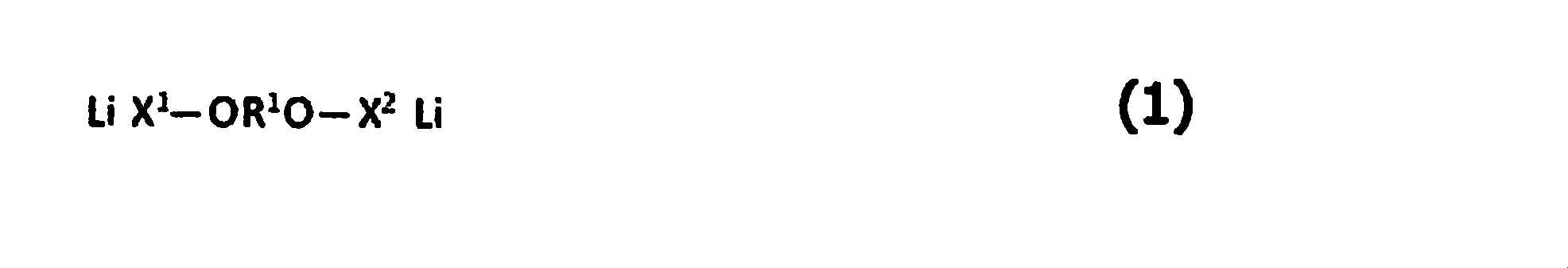

で表される1種以上の化合物を含み、かつ、
前記Cy面の単位質量当たりの前記式(1)~(3)で表される化合物の含有量をCy3(mol/g)とするとき、Cy3が1.60×10-4以上300×10-4以下である、[14]~[16]のいずれか1項に記載の非水系リチウム蓄電素子。
[18]前記Ay面に含有される前記式(1)~(3)で表される化合物の含有量をAy3(mol/g)とするとき、Cy3/Ay3が0.2以上20以下である、[17]に記載の非水系リチウム蓄電素子。
[19]前記リチウム化合物が、炭酸リチウム、酸化リチウム、又は水酸化リチウムである、[1]~[12]、[14]~[18]のいずれか1項に記載の非水系リチウム蓄電素子。
[20]前記リチウム化合物が炭酸リチウムであり、かつ、前記Cx面及びCy面の顕微ラマン分光測定により得られるイメージング画像において、炭酸イオンマッピングの面積割合をSx%及びSy%とするとき、Sx及びSyは、それぞれ1以上40以下であり、かつSx/Syが1.00以上2.00以下である、[14]~[19]のいずれか1項に記載の非水系リチウム蓄電素子。
[21]前記Cx面又はCy面を有する正極活物質層に含まれる正極活物質が、BJH法により算出した直径20Å以上500Å以下の細孔に由来するメソ孔量をV1(cc/g)、MP法により算出した直径20Å未満の細孔に由来するマイクロ孔量をV2(cc/g)とするとき、0.3<V1≦0.8、及び0.5≦V2≦1.0を満たし、かつ、BET法により測定される比表面積が1,500m2/g以上3,000m2/g以下を示す活性炭である、[14]~[20]のいずれか1項に記載の非水系リチウム蓄電素子。
[22]前記Cx面又はCy面を有する正極活物質層に含まれる正極活物質が、BJH法により算出した直径20Å以上500Å以下の細孔に由来するメソ孔量V1(cc/g)が0.8<V1≦2.5を満たし、MP法により算出した直径20Å未満の細孔に由来するマイクロ孔量V2(cc/g)が0.8<V2≦3.0を満たし、かつ、BET法により測定される比表面積が2,300m2/g以上4,000m2/g以下を示す活性炭である、[14]~[20]のいずれか1項に記載の非水系リチウム蓄電素子。
[23]前記負極活物質に対する前記リチウムイオンのドープ量が、前記負極活物質の単位質量当たり530mAh/g以上2,500mAh/g以下である、[1]~[12]、[14]~[22]のいずれか1項に記載の非水系リチウム蓄電素子。
[24]前記負極活物質のBET比表面積が100m2/g以上1,500m2/g以下である、[23]に記載の非水系リチウム蓄電素子。
[25]前記負極活物質に対する前記リチウムイオンのドープ量が、該負極活物質の単位質量当たり50mAh/g以上700mAh/g以下である、[1]~[12]、[14]~[22]のいずれか1項に記載の非水系リチウム蓄電素子。
[26]前記負極活物質のBET比表面積が1m2/g以上50m2/g以下である、[25]に記載の非水系リチウム蓄電素子。
[27]前記負極活物質の平均粒子径が1μm以上10μm以下である、[1]~[22]、[25]、[26]のいずれか1項に記載の非水系リチウム蓄電素子。
[28][1]~[27]の非水系リチウム蓄電素子を含む蓄電モジュール。
[29][1]~[27]の非水系リチウム蓄電素子又は[28]の蓄電モジュールを含む電力回生システム。
[30][1]~[27]の非水系リチウム蓄電素子又は[28]の蓄電モジュールを含む電力負荷平準化システム。
[31][1]~[27]の非水系リチウム蓄電素子又は[28]の蓄電モジュールを含む無停電電源システム。
[32][1]~[27]の非水系リチウム蓄電素子又は[28]の蓄電モジュールを含む非接触給電システム。
[33][1]~[27]の非水系リチウム蓄電素子又は[28]の蓄電モジュールを含むエナジーハーベストシステム。
[34][1]~[27]の非水系リチウム蓄電素子又は[28]の蓄電モジュールを含む蓄電システム。 The present inventors diligently studied to solve the above problems and repeated experiments. As a result, by securing the electron conductivity between the positive electrode active material by controlling the average particle diameter Y 1 having an average particle diameter of X 1 and the positive electrode active material of a lithium compound contained in the positive electrode, high output and high energy We found that it can be densified.
The present invention has been made based on this finding.
That is, the present invention is as follows:
[1] a positive electrode containing a lithium compound other than the active material, a negative electrode, a separator, a nonaqueous lithium battery elements consisting of a non-aqueous electrolyte containing lithium ions, an average particle diameter of the lithium compound when the X 1, 0.1 μm ≦ X 1 ≦ 10.0 μm, and when the average particle diameter of the positive electrode active material is Y 1 , 2.0 μm ≦ Y 1 ≦ 20.0 μm, X 1 <Y 1 , A non-aqueous lithium storage element in which the amount of the lithium compound contained therein is 1% by mass or more and 50% by mass or less.
[2] In the element mapping obtained by SEM-EDX of the positive electrode surface, average fluorine area overlap rate A 1 mapping to oxygen mapping binarized on the basis of the luminance values is 99% or less 40% The nonaqueous lithium storage element according to [1].
[3] In the element mapping obtained by BIB processed cathode section of SEM-EDX, at most 60% area overlapping ratio A 2 fluorine mapping more than 10% of the binarized oxygen mapped on the basis of the average value of the brightness values The non-aqueous lithium storage element according to [1] or [2].
[4] The X 1 is 0.5μm or more 5.0μm or less, [1] a non-aqueous lithium storage element according to any one of - [3].
[5] The non-aqueous lithium storage element according to any one of [1] to [4], wherein the amount of the lithium compound contained in the positive electrode is 2% by mass or more and 20% by mass or less.
[6] The negative electrode includes a non-porous negative electrode current collector and a negative electrode active material layer including a negative electrode active material provided on one or both surfaces of the negative electrode current collector,
The negative electrode active material includes a carbon material capable of occluding and releasing lithium ions,
At least one of the positive electrodes has a non-porous positive electrode current collector, and a positive electrode active material layer including a positive electrode active material provided on both surfaces of the positive electrode current collector,
Wherein the basis weight of the positive electrode active material layer on one surface of the positive electrode (C y plane) and C y1 (g / m 2) , the other side of the basis weight of the positive electrode active material layer (C x plane) C x1 (g / m 2 ), C y1 / C x1 is 0.70 or more and 0.98 or less,
When the amount of lithium compound per unit area on the Cy plane is C y2 (g / m 2 ) and the amount of lithium compound per unit area on the C x plane is C x2 (g / m 2 ), C y2 and C The non-aqueous lithium storage element according to any one of [1] to [5], wherein x2 is 0.10 or more and 20.0 or less, and C y2 / C x2 is 0.10 or more and 1.0 or less. .
[7] The positive electrode includes a positive electrode current collector, and a positive electrode active material layer including the positive electrode active material provided on one or both surfaces of the positive electrode current collector,
The negative electrode has a negative electrode current collector having no through holes, and first and second negative electrode active material layers including a negative electrode active material provided on both surfaces of the negative electrode current collector,
Each of the first and second negative electrode active material layers occludes lithium ions,
The solid 7 Li-NMR spectrum of the first negative electrode active material layer provided on the first surface of the negative electrode current collector is calculated from the peak area of −20 ppm to 60 ppm, and the first that absorbs the lithium ions. 1 negative active lithium per unit mass of material layers and q 1, and of the said a back surface of the first side negative electrode current collector and the second anode active material layer provided on the second surface of the solid 7 When the amount of lithium per unit mass of the second negative electrode active material layer occluded with the lithium ions calculated from the peak area of −20 ppm to 60 ppm with respect to the Li-NMR spectrum is q 2 , q 1 and q 2 The non-aqueous lithium storage element according to any one of [1] to [6], wherein the coefficient of variation CV is 0.001 or more and 0.500 or less.
[8] For the solid 7 Li-NMR spectrum of the positive electrode active material layer, the peak area in the spectrum range of −40 ppm to 40 ppm obtained by measurement with a repetition waiting time of 10 seconds is a, and the repetition waiting time is 3,000 seconds. The nonaqueous lithium storage element according to [7], wherein 1.04 ≦ b / a ≦ 5.56, where b is a peak area in a spectrum range of −40 ppm to 40 ppm obtained by the measurement.
[9] The non-aqueous system according to [7] or [8], wherein a BET specific surface area per unit volume of the first or second negative electrode active material layer is 20 m 2 / cc or more and 1,500 m 2 / cc or less. Lithium storage element.
[10] The nonaqueous lithium electricity storage device according to [7] or [8], wherein the BET specific surface area per unit volume of the first or second negative electrode active material layer is 1 m 2 / cc to 50 m 2 / cc. element.
[11] The positive electrode active material is derived from V 1 (cc / g) mesopore volume derived from pores having a diameter of 20 to 500 mm calculated by the BJH method, and from pores having a diameter of less than 20 mm calculated by the MP method. When the amount of micropores to be made is V 2 (cc / g), a ratio measured by the BET method that satisfies 0.3 <V 1 ≦ 0.8 and 0.5 ≦ V 2 ≦ 1.0 The nonaqueous lithium storage element according to any one of [1] to [10], which is activated carbon having a surface area of 1,500 m 2 / g or more and 3,000 m 2 / g or less.
[12] The positive electrode active material is derived from V 1 (cc / g) mesopore amount derived from pores having a diameter of 20 to 500 mm calculated by the BJH method, and from pores having a diameter of less than 20 mm calculated by the MP method. When the amount of micropores to be made is V 2 (cc / g), a ratio that satisfies 0.8 <V 1 ≦ 2.5 and 0.8 <V 2 ≦ 3.0, and is measured by the BET method The nonaqueous lithium storage element according to any one of [1] to [10], which is activated carbon having a surface area of 2,300 m 2 / g or more and 4,000 m 2 / g or less.
[13]
A positive electrode containing a lithium compound other than the positive electrode active material;
A negative electrode,
A separator;
A non-aqueous electrolyte containing lithium ions;
A non-aqueous lithium electricity storage device having
The positive electrode has a positive electrode current collector, and a positive electrode active material layer including a positive electrode active material provided on one or both surfaces of the positive electrode current collector,
The negative electrode has a negative electrode current collector having no through holes, and first and second negative electrode active material layers including a negative electrode active material provided on both surfaces of the negative electrode current collector,
Each of the first and second negative electrode active material layers occludes lithium ions,
The solid 7 Li-NMR spectrum of the first negative electrode active material layer provided on the first surface of the negative electrode current collector is calculated from the peak area of −20 ppm to 60 ppm, and the first that absorbs the lithium ions. the amount of lithium per unit mass of 1 negative electrode active material layer and q 1, the first surface wherein a back surface of said provided second surface of the negative electrode current collector second anode active solid material layer 7 Li for -NMR spectra are calculated from the peak area of -20 ppm ~ 60 ppm, when the amount of lithium per unit mass of the second anode active material layer which occludes lithium ions was q 2, variation of q 1 and q 2 The coefficient CV is 0.001 or more and 0.50 or less, and the nonaqueous lithium storage element is charged at an environmental temperature of 25 ° C., a cell voltage of 2.2 V to 3.8 V, and a rate of 300 C. When the electric cycle is performed 60,000 times, the internal resistance after the 60,000 charge / discharge cycles is Rb (Ω), and the internal resistance before starting the charge / discharge cycle is Ra (Ω). The non-aqueous lithium electricity storage element, wherein Rb / Ra is 0.9 or more and 2.0 or less.
[14] The active material is applied to both surfaces of the non-porous positive electrode current collector of the positive electrode,
A negative electrode active material capable of inserting and extracting lithium ions is applied to both surfaces of the non-porous negative electrode current collector of the negative electrode,
The basis weight of the positive electrode active material layer on one surface (C x surface) of the positive electrode is C x1 (g / m 2 ), and the basis weight of the positive electrode active material layer on the other surface (C y surface) is C y1 (g / M 2 ), C x1 / C y1 is 1.02 or more and 1.35 or less,
Anode active basis weight material layer and A y1 (g / m 2) , the negative electrode active material layer of the other surface (A x plane) of the one surface of the negative electrode facing the C y plane (A y plane) When the basis weight of A x1 (g / m 2 ) is A x1 / A y1 is 0.74 or more and 0.98 or less, and
The basis weight of the lithium compound of said C x plane and C x2 (g / m 2) , when the basis weight of said lithium compound of said C y plane and C y2 (g / m 2) , C x2 and C y2 is The nonaqueous lithium electricity storage device according to any one of [1] to [12], wherein each of them is 0.10 or more and 20.0 or less and C y2 / C x2 is 0.10 or more and 0.95 or less element.
[15] The nonaqueous lithium electricity storage device according to [14], wherein (C x1 + C x2 ) A x1 / (C y1 + C y2 ) A y1 is 0.80 or more and 1.32 or less.
[16] The non-aqueous lithium storage element according to [14] or [15], wherein the Cx plane and the Ax plane face each other.
[17] The Cy surface has the following formulas (1) to (3):
Including one or more compounds represented by:
When the content of the compound represented by the formulas (1) to (3) per unit mass on the Cy plane is C y3 (mol / g), C y3 is 1.60 × 10 −4 or more and 300 The nonaqueous lithium storage element according to any one of [14] to [16], which is × 10 −4 or less.
[18] When the content of the compounds represented by the formulas (1) to (3) contained in the A y plane is A y3 (mol / g), C y3 / A y3 is 0.2 or more. The nonaqueous lithium storage element according to [17], which is 20 or less.
[19] The non-aqueous lithium storage element according to any one of [1] to [12] and [14] to [18], wherein the lithium compound is lithium carbonate, lithium oxide, or lithium hydroxide.
[20] The area ratio of carbonate ion mapping is S x % and S y % in the imaging image obtained by micro Raman spectroscopy measurement of the C x plane and the C y plane, in which the lithium compound is lithium carbonate. S x and S y are each 1 or more and 40 or less, and S x / S y is 1.00 or more and 2.00 or less, according to any one of [14] to [19] Non-aqueous lithium storage element.
[21] The positive electrode active material contained in the positive electrode active material layer having the C x plane or the Cy plane has a mesopore amount derived from pores having a diameter of 20 mm or more and 500 mm or less calculated by the BJH method as V 1 (cc / g) When the amount of micropores derived from pores having a diameter of less than 20 mm calculated by the MP method is V 2 (cc / g), 0.3 <V 1 ≦ 0.8 and 0.5 ≦ V 2 Any one of [14] to [20], which is activated carbon that satisfies ≦ 1.0 and has a specific surface area measured by the BET method of 1,500 m 2 / g to 3,000 m 2 / g. The non-aqueous lithium storage element described in 1.
[22] The C x plane or C positive electrode active material contained in the positive electrode active material layer having a y plane, meso Anaryou V 1 derived from 500Å following pore calculated diameter 20Å or more by the BJH method (cc / g ) Satisfies 0.8 <V 1 ≦ 2.5, and the amount of micropores V 2 (cc / g) derived from pores having a diameter of less than 20 mm calculated by the MP method is 0.8 <V 2 ≦ 3.0. And [14] to [20], wherein the specific surface area measured by the BET method is 2,300 m 2 / g or more and 4,000 m 2 / g or less. Water-based lithium storage element.
[23] The lithium ion doping amount with respect to the negative electrode active material is 530 mAh / g or more and 2,500 mAh / g or less per unit mass of the negative electrode active material, [1] to [12], [14] to [14] 22] The nonaqueous lithium storage element according to any one of [22].
[24] The nonaqueous lithium storage element according to [23], wherein the negative electrode active material has a BET specific surface area of 100 m 2 / g or more and 1,500 m 2 / g or less.
[25] [1] to [12], [14] to [22], wherein a doping amount of the lithium ion with respect to the negative electrode active material is 50 mAh / g or more and 700 mAh / g or less per unit mass of the negative electrode active material The non-aqueous lithium electrical storage element of any one of these.
[26] The nonaqueous lithium storage element according to [25], wherein the negative electrode active material has a BET specific surface area of 1 m 2 / g or more and 50 m 2 / g or less.
[27] The non-aqueous lithium storage element according to any one of [1] to [22], [25], and [26], wherein the negative electrode active material has an average particle size of 1 μm to 10 μm.
[28] A power storage module including the non-aqueous lithium power storage element of [1] to [27].
[29] A power regeneration system including the nonaqueous lithium storage element according to [1] to [27] or the storage module according to [28].
[30] A power load leveling system including the non-aqueous lithium storage element of [1] to [27] or the storage module of [28].
[31] An uninterruptible power supply system including the nonaqueous lithium storage element of [1] to [27] or the storage module of [28].
[32] A non-contact power feeding system including the non-aqueous lithium electricity storage element of [1] to [27] or the electricity storage module of [28].
[33] An energy harvesting system including the nonaqueous lithium storage element of [1] to [27] or the storage module of [28].
[34] A power storage system including the nonaqueous lithium power storage element of [1] to [27] or the power storage module of [28].
本発明の非水系リチウム蓄電素子は以下の第一~第四の態様からなり、各態様は任意に組み合わせることができる。
[第一の態様]
本発明の非水系リチウム蓄電素子における第一の態様とは、
正極に活物質以外のリチウム化合物を含み、該リチウム化合物の平均粒子径をX1とするとき、0.1μm≦X1≦10.0μmであり、正極活物質の平均粒子径をY1とするとき、2.0μm≦Y1≦20.0μmであり、X1<Y1であり、該正極中に含まれる前記リチウム化合物の量が1質量%以上50質量%以下である、
非水系リチウム蓄電素子である。
[第二の態様]
又、本発明における第二の態様とは、
負極は、無孔状の負極集電体と、該負極集電体の片面又は両面上に設けられた、負極活物質を含む負極活物質層とを有し、
該負極活物質は、リチウムイオンを吸蔵及び放出可能な炭素材料を含み、
正極の少なくとも1つは、無孔状の正極集電体と、該正極集電体の両面上に設けられた、正極活物質を含む正極活物質層とを有し、
該正極の一方の面(Cy面)の正極活物質層の目付をCy1(g/m2)とし、他方の面(Cx面)の正極活物質層の目付をCx1(g/m2)とするとき、Cy1/Cx1は0.70以上0.98以下であり、
Cy面の単位面積当たりのリチウム化合物量をCy2(g/m2)とし、Cx面の単位面積当たりのリチウム化合物量をCx2(g/m2)とするとき、Cy2及びCx2は0.10以上20.0以下であり、Cy2/Cx2は0.10以上1.0以下である、
非水系リチウム蓄電素子である。
[第三の態様]
正極は、正極集電体と、該正極集電体の片面又は両面上に設けられた、該正極活物質を含む正極活物質層とを有し、
負極は、貫通孔を持たない負極集電体と、該負極集電体の両面上に設けられた、負極活物質を含む第1及び第2負極活物質層とを有し、
該第1及び第2負極活物質層は、それぞれリチウムイオンを吸蔵しており、
該負極集電体の第1面上に設けられた該第1負極活物質層の固体7Li-NMRスペクトルについて、-20ppm~60ppmのピーク面積より計算される、前記リチウムイオンを吸蔵した該第1負極活物質層の単位質量当たりのリチウム量をq1とし、かつ該第1面の裏面である該負極集電体の第2面上に設けられた該第2負極活物質層の固体7Li-NMRスペクトルについて、-20ppm~60ppmのピーク面積より計算される、該リチウムイオンを吸蔵した該第2負極活物質層の単位質量当たりのリチウム量をq2としたとき、q1とq2の変動係数CVが、0.001以上0.500以下である、
非水系リチウム蓄電素子である。
[第四の態様]
そして、本発明における第四の態様とは、
正極における無孔状の正極集電体の両面に前記活物質が塗布されており、
負極における無孔状の負極集電体の両面に、リチウムイオンを吸蔵及び放出可能な負極活物質が塗布されており、
正極の一方の面(Cx面)の正極活物質層の目付をCx1(g/m2)とし、もう片方の面(Cy面)の正極活物質層の目付をCy1(g/m2)とするとき、Cx1/Cy1が1.02以上1.35以下であり、
該Cy面と対向する該負極の一方の面(Ay面)の負極活物質層の目付をAy1(g/m2)とし、もう片方の面(Ax面)の負極活物質層の目付をAx1(g/m2)とするとき、Ax1/Ay1が0.74以上0.98以下であり、かつ
前記Cx面の該リチウム化合物の目付をCx2(g/m2)とし、該Cy面の該リチウム化合物の目付をCy2(g/m2)とするとき、Cx2及びCy2は、それぞれ0.10以上20.0以下であり、かつCy2/Cx2が0.10以上0.95以下である、
非水系リチウム蓄電素子である。
以下、各態様についての実施形態について詳しく説明する。 In general, a non-aqueous lithium storage element mainly includes a positive electrode, a negative electrode, a separator, an electrolytic solution, and an outer package. As the electrolytic solution, an organic solvent in which a lithium salt is dissolved (hereinafter referred to as a non-aqueous electrolytic solution) is used.
The non-aqueous lithium electricity storage device of the present invention comprises the following first to fourth aspects, and the aspects can be arbitrarily combined.
[First embodiment]
The first aspect of the non-aqueous lithium electricity storage device of the present invention is
Positive electrode comprises a lithium compound other than the active material, the average particle diameter of the lithium compound when the X 1, a 0.1μm ≦ X 1 ≦ 10.0μm, an average particle diameter of the positive electrode active material Y 1 When 2.0 μm ≦ Y 1 ≦ 20.0 μm, X 1 <Y 1 , and the amount of the lithium compound contained in the positive electrode is 1% by mass or more and 50% by mass or less,
It is a non-aqueous lithium storage element.
[Second embodiment]
The second aspect of the present invention is
The negative electrode has a non-porous negative electrode current collector and a negative electrode active material layer including a negative electrode active material provided on one or both surfaces of the negative electrode current collector,
The negative electrode active material includes a carbon material capable of occluding and releasing lithium ions,
At least one of the positive electrodes has a non-porous positive electrode current collector, and a positive electrode active material layer including a positive electrode active material provided on both surfaces of the positive electrode current collector,
The basis weight of the positive electrode active material layer on one surface of the positive electrode (C y plane) and C y1 (g / m 2) , the other side of the basis weight of the positive electrode active material layer (C x plane) C x1 (g / m 2 ), C y1 / C x1 is 0.70 or more and 0.98 or less,
When the amount of lithium compound per unit area on the Cy plane is C y2 (g / m 2 ) and the amount of lithium compound per unit area on the C x plane is C x2 (g / m 2 ), C y2 and C x2 is 0.10 or more and 20.0 or less, and C y2 / C x2 is 0.10 or more and 1.0 or less.
It is a non-aqueous lithium storage element.
[Third embodiment]
The positive electrode has a positive electrode current collector and a positive electrode active material layer including the positive electrode active material provided on one or both surfaces of the positive electrode current collector,
The negative electrode has a negative electrode current collector having no through-holes, and first and second negative electrode active material layers including a negative electrode active material provided on both surfaces of the negative electrode current collector,
Each of the first and second negative electrode active material layers occludes lithium ions,
The solid 7 Li-NMR spectrum of the first negative electrode active material layer provided on the first surface of the negative electrode current collector is calculated from the peak area of -20 ppm to 60 ppm, and the amount of lithium per unit mass of 1 negative electrode active material layer and q 1, and the second negative active solid material layer 7 provided on the second surface of the negative electrode current collector is a rear surface of the first surface When the amount of lithium per unit mass of the second negative electrode active material layer occluded with the lithium ions calculated from the peak area of −20 ppm to 60 ppm for the Li-NMR spectrum is q 2 , q 1 and q 2 The coefficient of variation CV is 0.001 or more and 0.500 or less,
It is a non-aqueous lithium storage element.
[Fourth aspect]
And with the 4th mode in the present invention,
The active material is applied to both surfaces of a non-porous positive electrode current collector in the positive electrode,
A negative electrode active material capable of inserting and extracting lithium ions is applied to both surfaces of a non-porous negative electrode current collector in the negative electrode,
The basis weight of the positive electrode active material layer on one surface (C x surface) of the positive electrode is C x1 (g / m 2 ), and the basis weight of the positive electrode active material layer on the other surface (C y surface) is C y1 (g / m 2 ). m 2 ), C x1 / C y1 is 1.02 or more and 1.35 or less,
The basis weight of the negative electrode active material layer on one surface of the negative electrode facing the said C y plane (A y plane) and A y1 (g / m 2) , the negative electrode active material layer of the other surface (A x plane) when the the a x1 (g / m 2) basis weight, a x1 / a y1 is 0.98 or less than 0.74, and wherein the C a basis weight of the lithium compound in the x plane C x2 (g / m 2) and, when the basis weight of said lithium compound of said C y plane and C y2 (g / m 2) , C x2 and C y2 is 0.10 or more 20.0 or less, and C y2 / C x2 is 0.10 or more and 0.95 or less,
It is a non-aqueous lithium storage element.
Hereinafter, embodiments of each aspect will be described in detail.
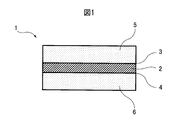
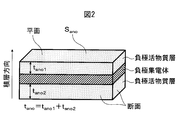
電極積層体(14)において、少なくとも1つの正極は、無孔状の正極集電体(9)を含み、かつ無孔状の正極集電体(9)の両面に活物質が塗布されることにより、正極活物質層Cx面(7)を有する正極活物質層、及び正極活物質層Cy面(8)を有する正極活物質層が、それぞれ配置される。
電極積層体(14)において、少なくとも1つの負極は、無孔状の負極集電体(12)を含み、かつ無孔状の負極集電体(12)の両面に、リチウムイオンを吸蔵及び放出可能な負極活物質が塗布されることにより、負極活物質層Ax面(10)を有する負極活物質層、及び負極活物質層Ay面(11)を有する負極活物質層が、それぞれ配置される。
図3に示されるように、正極活物質層Cx面(7)と負極活物質層Ax面(10)が、セパレータ(13)を介して対向し、かつ/又は正極活物質層Cy面(8)と負極活物質層Ay面(11)が、セパレータ(13)を介して対向する。
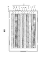
図3には示されていないが、正極集電体の片面のみに正極活物質層が形成されている片面正極又は正極集電体の両面に正極活物質層が形成されている両面正極が、電極積層体の最も外側に配置されていてもよいし、負極集電体の片面のみに負極活物質層が形成されている片面負極又は負極集電体の両面に負極活物質層が形成されている両面負極が、電極積層体の最も外側に配置されていてもよい。 FIG. 3 shows the facing state of the surface of the positive electrode active material layer and the surface of the negative electrode active material layer in the non-aqueous lithium electricity storage device according to the fourth embodiment of the present invention. The exterior body (15) of the non-aqueous lithium energy storage device according to the embodiment of the present invention houses an electrode laminate (14) formed by laminating a positive electrode and a negative electrode via a separator (13).
In the electrode laminate (14), at least one positive electrode includes a non-porous positive electrode current collector (9), and an active material is applied to both surfaces of the non-porous positive electrode current collector (9). the positive electrode active material layer having positive electrode active material layer C x plane (7), and a positive electrode active material layer having positive electrode active material layer C y plane (8) are arranged.
In the electrode laminate (14), at least one negative electrode includes a non-porous negative electrode current collector (12), and occludes and releases lithium ions on both sides of the non-porous negative electrode current collector (12). by active material capable is applied, the negative electrode active material layer having a negative electrode active material layer a x surface (10), and a negative electrode active material layer having a negative electrode active material layer a y plane (11), respectively arranged Is done.
As shown in FIG. 3, the positive electrode active material layer C x surface (7) and the negative electrode active material layer A x surface (10) face each other with a separator (13) and / or the positive electrode active material layer C y. The face (8) and the negative electrode active material layer Ay face (11) face each other via the separator (13).
Although not shown in FIG. 3, a single-sided positive electrode in which a positive electrode active material layer is formed only on one side of the positive electrode current collector or a double-sided positive electrode in which a positive electrode active material layer is formed on both sides of the positive electrode current collector, The negative electrode active material layer may be formed on both sides of the single-sided negative electrode or the negative electrode current collector in which the negative electrode active material layer may be disposed only on one side of the negative electrode current collector The double-sided negative electrode may be arranged on the outermost side of the electrode laminate.
本発明の正極は、正極集電体と、その片面又は両面に存在する正極活物質層とを有する。また、本発明の第二及び第四の態様における正極の少なくとも1つは、無孔状の正極集電体と、その両面上に設けられた、正極活物質を含む正極活物質層とを有する。 <Positive electrode>
The positive electrode of the present invention has a positive electrode current collector and a positive electrode active material layer present on one side or both sides thereof. Further, at least one of the positive electrodes in the second and fourth aspects of the present invention has a non-porous positive electrode current collector and a positive electrode active material layer including a positive electrode active material provided on both surfaces thereof. .
本発明における前記正極は、蓄電素子組み立て前の正極前駆体として、リチウム化合物を含むことが好ましい。後述のように、本発明では蓄電素子組み立て工程内で、負極にリチウムイオンをプレドープすることが好ましいが、そのプレドープ方法としては、前記リチウム化合物を含む正極前駆体、負極、セパレータ、外装体、及び非水系電解液を用いて蓄電素子を組み立てた後に、正極前駆体と負極との間に電圧を印加することが好ましい。前記リチウム化合物は前記正極前駆体の正極集電体上に形成された正極活物質層に含有されることが好ましい。
ここで、本発明では、リチウムドープ工程前における正極状態のことを正極前駆体、リチウムドープ工程後における正極状態のことを正極と定義する。 In the present specification, “non-porous positive electrode current collector” means that lithium ions pass through the positive electrode current collector at least in the coated region of the positive electrode active material layer, and the lithium ions are uniform on the front and back surfaces of the positive electrode. It means a positive electrode current collector that does not have pores to the extent that it can be converted. Therefore, within the range where the effect of the present invention is exerted, the positive electrode current collector having a very small diameter or a small amount of holes and the positive electrode current collector having holes in a region where the positive electrode active material layer is not coated are also excluded. is not.
The positive electrode in the present invention preferably contains a lithium compound as a positive electrode precursor before assembly of the storage element. As will be described later, in the present invention, it is preferable to pre-dope lithium ions into the negative electrode in the process of assembling the power storage element. As the pre-doping method, the positive electrode precursor containing the lithium compound, the negative electrode, the separator, the outer package, and It is preferable to apply a voltage between the positive electrode precursor and the negative electrode after assembling the electricity storage device using the non-aqueous electrolyte. The lithium compound is preferably contained in a positive electrode active material layer formed on the positive electrode current collector of the positive electrode precursor.
Here, in this invention, the positive electrode state before a lithium dope process is defined as a positive electrode precursor, and the positive electrode state after a lithium dope process is defined as a positive electrode.
前記正極活物質層は、炭素材料を含む正極活物質を含有することが好ましく、これ以外に、必要に応じて、導電性フィラー、結着剤、分散安定剤等の任意成分を含んでいてもよい。
また、正極前駆体の正極活物質層には、リチウム化合物が含有されることが好ましい。 [Positive electrode active material layer]
The positive electrode active material layer preferably contains a positive electrode active material containing a carbon material. In addition, the positive electrode active material layer may contain optional components such as a conductive filler, a binder, and a dispersion stabilizer as necessary. Good.
The positive electrode active material layer of the positive electrode precursor preferably contains a lithium compound.
前記正極活物質としては、炭素材料を含むことが好ましい。この炭素材料としては、カーボンナノチューブ、導電性高分子、又は多孔性の炭素材料を使用することがより好ましく、さらに好ましくは活性炭である。正極活物質には1種類以上の材料を混合して使用してもよく、炭素材料以外の材料(例えばリチウムと遷移金属との複合酸化物等)を含んでもよい。
好ましくは前記正極活物質の総量に対する前記炭素材料の含有率が50質量%以上であり、より好ましくは70質量%以上である。前記炭素材料の含有率が100質量%であることができるが、他の材料の併用による効果を良好に得る観点から、例えば、90質量%以下であることが好ましく、80質量%以下であってもよい。
活性炭を正極活物質として用いる場合、活性炭の種類及びその原料には特に制限はない。しかし、高い入出力特性と、高いエネルギー密度とを両立させるために、活性炭の細孔を最適に制御することが好ましい。具体的には、BJH法により算出した直径20Å以上500Å以下の細孔に由来するメソ孔量をV1(cc/g)、MP法により算出した直径20Å未満の細孔に由来するマイクロ孔量をV2(cc/g)とするとき、
(1)高い入出力特性のためには、0.3<V1≦0.8、及び0.5≦V2≦1.0を満たし、かつ、BET法により測定される比表面積が1,500m2/g以上3,000m2/g以下である活性炭(以下、活性炭1ともいう。)が好ましく、また、
(2)高いエネルギー密度を得るためには、0.8<V1≦2.5、及び0.8<V2≦3.0を満たし、かつ、BET法により測定される比表面積が2,300m2/g以上4,000m2/g以下である活性炭(以下、活性炭2ともいう。)が好ましい。
以下、前記(1)活性炭1及び前記(2)活性炭2について、個別に順次説明していく。 [Positive electrode active material]
The positive electrode active material preferably contains a carbon material. As this carbon material, it is more preferable to use a carbon nanotube, a conductive polymer, or a porous carbon material, and more preferably activated carbon. One or more kinds of materials may be mixed and used for the positive electrode active material, and materials other than the carbon material (for example, a composite oxide of lithium and a transition metal) may be included.
Preferably, the content of the carbon material with respect to the total amount of the positive electrode active material is 50% by mass or more, more preferably 70% by mass or more. Although the content rate of the carbon material can be 100% by mass, it is preferably 90% by mass or less, for example, 80% by mass or less from the viewpoint of obtaining the effect of the combined use of other materials. Also good.
When using activated carbon as a positive electrode active material, there is no restriction | limiting in particular in the kind and raw material of activated carbon. However, in order to achieve both high input / output characteristics and high energy density, it is preferable to optimally control the pores of the activated carbon. Specifically, the amount of mesopores derived from pores having a diameter of 20 to 500 mm calculated by the BJH method is V 1 (cc / g), and the amount of micropores derived from pores having a diameter of less than 20 mm calculated by the MP method. Is V 2 (cc / g),
(1) For high input / output characteristics, 0.3 <V 1 ≦ 0.8 and 0.5 ≦ V 2 ≦ 1.0 are satisfied, and the specific surface area measured by the BET method is 1, Activated carbon (hereinafter also referred to as activated carbon 1) having a mass of 500 m 2 / g to 3,000 m 2 / g is preferred.
(2) In order to obtain a high energy density, 0.8 <V 1 ≦ 2.5 and 0.8 <V 2 ≦ 3.0 are satisfied, and the specific surface area measured by the BET method is 2, Activated carbon (hereinafter also referred to as activated carbon 2) of 300 m 2 / g to 4,000 m 2 / g is preferable.
Hereinafter, the (1) activated carbon 1 and the (2) activated
活性炭1のメソ孔量V1は、正極材料を蓄電素子に組み込んだときの入出力特性を大きくする点で、0.3cc/gより大きい値であることが好ましい。一方で、正極の嵩密度の低下を抑える点から、V1は0.8cc/g以下であることが好ましい。前記V1は、より好ましくは0.35cc/g以上0.7cc/g以下、更に好ましくは0.4cc/g以上0.6cc/g以下である。
活性炭1のマイクロ孔量V2は、活性炭の比表面積を大きくし、容量を増加させるために、0.5cc/g以上であることが好ましい。一方で、活性炭の嵩を抑え、電極としての密度を増加させ、単位体積当たりの容量を増加させるという点から、V2は1.0cc/g以下であることが好ましい。前記V2は、より好ましくは0.6cc/g以上1.0cc/g以下、更に好ましくは0.8cc/g以上1.0cc/g以下である。 (Activated carbon 1)
The mesopore amount V 1 of the activated carbon 1 is preferably a value larger than 0.3 cc / g from the viewpoint of increasing the input / output characteristics when the positive electrode material is incorporated in the storage element. On the other hand, from the viewpoint of suppressing a decrease in the bulk density of the positive electrode, V 1 is preferably 0.8 cc / g or less. V 1 is more preferably 0.35 cc / g or more and 0.7 cc / g or less, and further preferably 0.4 cc / g or more and 0.6 cc / g or less.
The micropore amount V 2 of the activated carbon 1 is preferably 0.5 cc / g or more in order to increase the specific surface area of the activated carbon and increase the capacity. On the other hand, reducing the volume of the activated carbon increases the density of the electrode, from the viewpoint of increasing the capacity per unit volume, it is preferred that V 2 is not more than 1.0 cc / g. V 2 is more preferably 0.6 cc / g or more and 1.0 cc / g or less, and further preferably 0.8 cc / g or more and 1.0 cc / g or less.
活性炭1の平均細孔径は、得られる蓄電素子の出力を最大にする点から、17Å以上であることが好ましく、18Å以上であることがより好ましく、20Å以上であることが最も好ましい。また容量を最大にする点から、活性炭1の平均細孔径は25Å以下であることが好ましい。
活性炭1のBET比表面積は、1,500m2/g以上3,000m2/g以下であることが好ましく、1,500m2/g以上2,500m2/g以下であることがより好ましい。BET比表面積が1,500m2/g以上の場合には、良好なエネルギー密度が得られ易く、他方、BET比表面積が3,000m2/g以下の場合には、電極の強度を保つためにバインダーを多量に入れる必要がないので、電極体積当たりの性能が高くなる。
前記のような特徴を有する活性炭1は、例えば、以下に説明する原料及び処理方法を用いて得ることができる。 The ratio of meso Anaryou V 1 relative to the micropore volume V 2 (V 1 / V 2 ) is preferably in the range of 0.3 ≦ V 1 / V 2 ≦ 0.9. That is, V 1 / V 2 is 0.3 or more from the viewpoint of increasing the ratio of the mesopore amount to the micropore amount to such an extent that the decrease in output characteristics can be suppressed while maintaining a high capacity. It is preferable. On the other hand, V 1 / V 2 is 0.9 or less from the viewpoint of increasing the ratio of the micropore amount to the mesopore amount to such an extent that the decrease in capacity can be suppressed while maintaining high output characteristics. Is preferred. More preferred V 1 / V 2 range 0.4 ≦ V 1 / V 2 ≦ 0.7, further preferred V 1 / V 2 range is 0.55 ≦ V 1 / V 2 ≦ 0.7.
The average pore diameter of the activated carbon 1 is preferably 17 mm or more, more preferably 18 mm or more, and most preferably 20 mm or more from the viewpoint of maximizing the output of the obtained electricity storage device. Moreover, from the point of maximizing the capacity, the average pore diameter of the activated carbon 1 is preferably 25 mm or less.
BET specific surface area of the activated carbon 1 is preferably from 1,500 m 2 / g or more 3,000 m 2 / g, more preferably not more than 1,500 m 2 / g or more 2,500 m 2 / g. When the BET specific surface area is 1,500 m 2 / g or more, good energy density is easily obtained. On the other hand, when the BET specific surface area is 3,000 m 2 / g or less, the strength of the electrode is maintained. Since there is no need to add a large amount of binder, the performance per electrode volume is increased.
The activated carbon 1 having the above-described characteristics can be obtained using, for example, the raw materials and processing methods described below.
これらの原料を前記活性炭1とするための炭化及び賦活の方式としては、例えば、固定床方式、移動床方式、流動床方式、スラリー方式、ロータリーキルン方式等の既知の方式を採用できる。 In this embodiment, the carbon source used as a raw material of the activated carbon 1 is not particularly limited. For example, plant materials such as wood, wood flour, coconut husk, pulp by-products, bagasse, and molasses; peat, lignite, lignite, bituminous coal, anthracite, petroleum distillation residue components, petroleum pitch, coke, coal tar, etc. Fossil-based raw materials; various synthetic resins such as phenol resin, vinyl chloride resin, vinyl acetate resin, melamine resin, urea resin, resorcinol resin, celluloid, epoxy resin, polyurethane resin, polyester resin, polyamide resin; polybutylene, polybutadiene, polychloroprene, etc. Synthetic rubber, other synthetic wood, synthetic pulp and the like, and carbides thereof. Among these raw materials, from the viewpoint of mass production and cost, plant raw materials such as coconut shells and wood flour, and their carbides are preferable, and coconut shell carbides are particularly preferable.
As a method of carbonization and activation for using these raw materials as the activated carbon 1, known methods such as a fixed bed method, a moving bed method, a fluidized bed method, a slurry method, and a rotary kiln method can be employed.
前記炭化方法により得られた炭化物の賦活方法としては、水蒸気、二酸化炭素、酸素等の賦活ガスを用いて焼成するガス賦活法が好ましく用いられる。このうち、賦活ガスとして、水蒸気又は二酸化炭素を使用する方法が好ましい。
この賦活方法では、賦活ガスを0.5~3.0kg/h(好ましくは0.7~2.0kg/h)の割合で供給しながら、前記炭化物を3~12時間(好ましくは5~11時間、更に好ましくは6~10時間)かけて800~1,000℃まで昇温して賦活するのが好ましい。
更に、前記炭化物の賦活処理に先立ち、予め前記炭化物を1次賦活してもよい。この1次賦活では、通常、炭素材料を水蒸気、二酸化炭素、酸素等の賦活ガスを用いて、900℃未満の温度で焼成してガス賦活する方法が、好ましく採用できる。
前記炭化方法における焼成温度及び焼成時間と、前記賦活方法における賦活ガス供給量、昇温速度及び最高賦活温度とを適宜組み合わせることにより、本実施形態において使用できる、前記の特徴を有する活性炭1を製造することができる。 As a carbonization method of these raw materials, nitrogen, carbon dioxide, helium, argon, xenon, neon, carbon monoxide, an exhaust gas such as combustion exhaust gas, or other gases mainly composed of these inert gases. Examples of the method include baking using a mixed gas at about 400 to 700 ° C. (preferably 450 to 600 ° C.) for about 30 minutes to 10 hours.
As a method for activating the carbide obtained by the carbonization method, a gas activation method in which firing is performed using an activation gas such as water vapor, carbon dioxide, or oxygen is preferably used. Among these, a method using water vapor or carbon dioxide as the activation gas is preferable.
In this activation method, the carbide is supplied for 3 to 12 hours (preferably 5 to 11) while supplying an activation gas at a rate of 0.5 to 3.0 kg / h (preferably 0.7 to 2.0 kg / h). It is preferable to activate by heating to 800 to 1,000 ° C. over a period of time, more preferably 6 to 10 hours.
Furthermore, prior to the activation treatment of the carbide, the carbide may be activated in advance. In this primary activation, a method of gas activation by firing a carbon material at a temperature of less than 900 ° C. using an activation gas such as water vapor, carbon dioxide, oxygen or the like can be preferably employed.
By appropriately combining the firing temperature and firing time in the carbonization method with the activation gas supply amount, the heating rate and the maximum activation temperature in the activation method, the activated carbon 1 having the above-described characteristics that can be used in the present embodiment is manufactured. can do.
前記平均粒子径が2μm以上であると、活物質層の密度が高いために電極体積当たりの容量が高くなる傾向がある。ここで、平均粒子径が小さいと耐久性が低いという欠点を招来する場合があるが、平均粒子径が2μm以上であればそのような欠点が生じ難い。一方で、平均粒子径が20μm以下であると、高速充放電には適合し易くなる傾向がある。前記平均粒子径は、より好ましくは2~15μmであり、更に好ましくは3~10μmである。 The average particle diameter of the activated carbon 1 is preferably 2 to 20 μm.
When the average particle size is 2 μm or more, the capacity per electrode volume tends to be high because the density of the active material layer is high. Here, if the average particle size is small, there may be a drawback that the durability is low. However, if the average particle size is 2 μm or more, such a defect hardly occurs. On the other hand, when the average particle size is 20 μm or less, it tends to be easily adapted to high-speed charge / discharge. The average particle diameter is more preferably 2 to 15 μm, still more preferably 3 to 10 μm.
活性炭2のメソ孔量V1は、正極材料を蓄電素子に組み込んだときの出力特性を大きくする観点から、0.8cc/gより大きい値であることが好ましい一方、蓄電素子の容量の低下を抑える観点から、V1は2.5cc/g以下であることが好ましい。前記V1は、より好ましくは1.00cc/g以上2.0cc/g以下、さらに好ましくは、1.2cc/g以上1.8cc/g以下である。
他方、活性炭2のマイクロ孔量V2は、活性炭の比表面積を大きくし、容量を増加させるために、0.8cc/gより大きい値であることが好ましい一方、活性炭の電極としての密度を増加させ、単位体積当たりの容量を増加させるという観点から、V2は3.0cc/g以下であることが好ましい。前記V2は、より好ましくは1.0cc/gより大きく2.5cc/g以下、更に好ましくは1.5cc/g以上2.5cc/g以下である。
上述したメソ孔量及びマイクロ孔量を有する活性炭2は、従来の電気二重層キャパシタ又はリチウムイオンキャパシタ用として使用されていた活性炭よりもBET比表面積が高いものである。活性炭2のBET比表面積の具体的な値としては、2,300m2/g以上4,000m2/g以下であることが好ましく、3,200m2/g以上3,800m2/g以下であることがより好ましい。BET比表面積が2,300m2/g以上の場合には、良好なエネルギー密度が得られ易く、他方、BET比表面積が4,000m2/g以下の場合には、電極の強度を保つためにバインダーを多量に入れる必要がないので、電極体積当たりの性能が高くなる。 (Activated carbon 2)
The mesopore amount V 1 of the activated
On the other hand, the micropore volume V 2 of the activated carbon 2 is preferably a value larger than 0.8 cc / g in order to increase the specific surface area of the activated carbon and increase the capacity, while increasing the density of the activated carbon as an electrode. From the viewpoint of increasing the capacity per unit volume, V 2 is preferably 3.0 cc / g or less. V 2 is more preferably greater than 1.0 cc / g and not greater than 2.5 cc / g, and still more preferably not less than 1.5 cc / g and not greater than 2.5 cc / g.
The activated
活性炭2の原料として用いられる炭素質材料としては、通常活性炭原料として用いられる炭素源であれば特に限定されるものではなく、例えば、木材、木粉、ヤシ殻等の植物系原料;石油ピッチ、コークス等の化石系原料;フェノール樹脂、フラン樹脂、塩化ビニル樹脂、酢酸ビニル樹脂、メラミン樹脂、尿素樹脂、レゾルシノール樹脂等の各種合成樹脂等が挙げられる。これらの原料の中でも、フェノール樹脂、及びフラン樹脂は、高比表面積の活性炭を作製するのに適しており特に好ましい。
これらの原料を炭化する方式、或いは賦活処理時の加熱方法としては、例えば、固定床方式、移動床方式、流動床方式、スラリー方式、ロータリーキルン方式等の公知の方式が挙げられる。加熱時の雰囲気は窒素、二酸化炭素、ヘリウム、アルゴン等の不活性ガス、又はこれらの不活性ガスを主成分として他のガスとの混合したガスが用いられる。炭化温度は400~700℃程度で0.5~10時間程度焼成する方法が一般的である。
炭化物の賦活方法としては、水蒸気、二酸化炭素、酸素等の賦活ガスを用いて焼成するガス賦活法、及びアルカリ金属化合物と混合した後に加熱処理を行うアルカリ金属賦活方があるが、高比表面積の活性炭を作製するにはアルカリ金属賦活法が好ましい。 The activated
The carbonaceous material used as a raw material for the activated
Examples of the method for carbonizing these raw materials or the heating method during the activation treatment include known methods such as a fixed bed method, a moving bed method, a fluidized bed method, a slurry method, and a rotary kiln method. The atmosphere at the time of heating is an inert gas such as nitrogen, carbon dioxide, helium, or argon, or a gas mixed with other gases containing these inert gases as a main component. In general, the carbonization temperature is about 400 to 700 ° C., and the firing is performed for about 0.5 to 10 hours.
Examples of the activation method of the carbide include a gas activation method in which firing is performed using an activation gas such as water vapor, carbon dioxide, and oxygen, and an alkali metal activation method in which heat treatment is performed after mixing with an alkali metal compound. An alkali metal activation method is preferable for producing activated carbon.
マイクロ孔量を大きくし、メソ孔量を大きくしないためには、賦活する際に炭化物の量を多めにしてKOHと混合するとよい。マイクロ孔量及びメソ孔量の双方を大きくするためには、KOHの量を多めに使用するとよい。また、主としてメソ孔量を大きくするためには、アルカリ賦活処理を行った後に水蒸気賦活を行うことが好ましい。
活性炭2の平均粒子径は2μm以上20μm以下であることが好ましい。活性炭2の平均粒子径はより好ましくは3μm以上10μm以下である。 In this activation method, mixing was performed so that the mass ratio of the carbide to the alkali metal compound such as KOH or NaOH was 1: 1 or more (the amount of the alkali metal compound was the same as or greater than the amount of the carbide). Thereafter, heating is performed in the range of 600 to 900 ° C. in an inert gas atmosphere for 0.5 to 5 hours, and then the alkali metal compound is washed and removed with an acid and water, followed by drying.
In order to increase the amount of micropores and not increase the amount of mesopores, a larger amount of carbides may be mixed with KOH when activated. In order to increase both the amount of micropores and the amount of mesopores, a larger amount of KOH may be used. In order to mainly increase the amount of mesopores, it is preferable to perform water vapor activation after alkali activation treatment.
The average particle diameter of the activated
活性炭1及び2は、それぞれ、1種の活性炭であってもよいし、2種以上の活性炭の混合物であって前記した各々の特性値を混合物全体として示すものであってもよい。
前記の活性炭1及び2は、これらのうちのいずれか一方を選択して使用してもよいし、両者を混合して使用してもよい。
正極活物質は、活性炭1及び2以外の材料(例えば、前記特定のV1及び/若しくはV2を有さない活性炭、又は活性炭以外の材料(例えば、リチウムと遷移金属との複合酸化物等))を含んでもよい。例示の態様において、活性炭1の含有量、又は活性炭2の含有量、又は活性炭1及び2の合計含有量が、それぞれ、全正極活物質の50質量%より多いことが好ましく、70質量%以上がより好ましく、90質量%以上が更に好ましく、100質量%であることが最も好ましい。
正極活物質層における正極活物質の含有割合は、正極前駆体における正極活物質層の全質量を基準として、35質量%以上95質量%以下であることが好ましい。正極活物質の含有割合の上限としては、45質量%以上であることがより好ましく、55質量%以上であることがさらに好ましい。一方、正極活物質の含有割合の下限としては、90質量%以下であることがより好ましく、85質量%以下であることが更に好ましい。この範囲の含有割合とすることにより、好適な充放電特性を発揮する。 (Use mode of activated carbon)
Each of the activated
The activated
The positive electrode active material is a material other than activated carbon 1 and 2 (for example, activated carbon not having the specific V 1 and / or V 2 or a material other than activated carbon (for example, a composite oxide of lithium and transition metal). ) May be included. In the illustrated embodiment, the content of the activated carbon 1, or the content of the activated
The content ratio of the positive electrode active material in the positive electrode active material layer is preferably 35% by mass or more and 95% by mass or less based on the total mass of the positive electrode active material layer in the positive electrode precursor. As an upper limit of the content rate of a positive electrode active material, it is more preferable that it is 45 mass% or more, and it is further more preferable that it is 55 mass% or more. On the other hand, as a minimum of the content rate of a positive electrode active material, it is more preferable that it is 90 mass% or less, and it is still more preferable that it is 85 mass% or less. By setting the content ratio in this range, suitable charge / discharge characteristics are exhibited.
本明細書では、リチウム化合物は、リチウムを含有する物質を意味するが、蓄電素子の充放電時に電極中でファラデー反応又は非ファラデー反応に関与する活物質を除くものとする。
本実施形態におけるリチウム化合物としては、炭酸リチウム、酸化リチウム、水酸化リチウム、フッ化リチウム、塩化リチウム、シュウ化リチウム、ヨウ化リチウム、窒化リチウム、シュウ酸リチウム、及び酢酸リチウムから選択される1種以上が好適に用いられる。中でも、炭酸リチウム、酸化リチウム、及び水酸化リチウムがより好適であり、空気中での取り扱いが可能であり、かつ吸湿性が低いという観点から炭酸リチウムがさらに好適に用いられる。このようなリチウム化合物は、電圧の印加によって分解し、負極へのリチウムドープのドーパント源として機能するとともに、正極活物質層において空孔を形成するから、電解液の保持性に優れ、イオン伝導性に優れる正極を形成することができる。前記リチウム化合物の他に、炭酸ナトリウム、炭酸カリウム、炭酸ルビジウム、及び炭酸セシウムから選択されるアルカリ金属炭酸塩を1種以上用いることもできる。非水系電解液として、後述するLiPF6等のリチウム塩を予め溶解させた電解液を用いる場合には、前記アルカリ金属炭酸塩を単独で用いることもできる。正極前駆体中に含まれるリチウム化合物は1種でもよく、2種以上のリチウム化合物を含んでいてもよく、リチウム化合物と他のアルカリ金属炭酸塩を混合して用いてもよい。
また、本実施形態の正極前駆体としては少なくとも1種のリチウム化合物を含んでいればよく、リチウム化合物の他に、下記式におけるMをNa、K、Rb、及びCsから選ばれる1種以上として、
M2O等の酸化物、
MOH等の水酸化物、
MFやMCl等のハロゲン化物、
M2(CO2)2等の蓚酸塩、
RCOOM(式中、RはH、アルキル基、又はアリール基である)等のカルボン酸塩
を1種以上含んでいてもよい。
また、正極前駆体は、BeCO3、MgCO3、CaCO3、SrCO3、又はBaCO3から選ばれるアルカリ土類金属炭酸塩、並びにアルカリ土類金属酸化物、アルカリ土類金属水酸化物、アルカリ土類金属ハロゲン化物、アルカリ土類金属シュウ酸塩、及びアルカリ土類金属カルボン酸塩を1種以上含んでいてもよい。
リチウム化合物の微粒子化には、様々な方法を用いることができる。例えば、ボールミル、ビーズミル、リングミル、ジェットミル、ロッドミル等の粉砕機を使用することができる。
正極中に含まれるリチウム化合物の量は1質量%以上50質量%以下であることが好ましい。更に好ましくは、2質量%以上30質量%以下である。リチウム化合物の量が1質量%以上であれば、高負荷充放電サイクルで生成するフッ素イオンを吸着する十分な量の炭酸リチウムが存在するため高負荷充放電サイクル特性が向上する。リチウム化合物の量が50質量%以下であれば、非水系リチウム蓄電素子のエネルギー密度を高めることができる。
正極活物質層におけるリチウム化合物の含有割合は、正極前駆体における正極活物質層の全質量を基準として、10質量%以上60質量%以下であることが好ましく、20質量%以上50質量%以下であることがより好ましい。この範囲の含有割合とすることにより、負極へのドーパント源として好適な機能を発揮するとともに、正極に適当な程度の多孔性を付与することができ、両者相俟って高負荷充放電効率に優れる蓄電素子を与えることができ、好ましい。 (Lithium compound)
In this specification, a lithium compound means a substance containing lithium, but excludes an active material involved in a Faraday reaction or a non-Faraday reaction in an electrode during charge / discharge of a storage element.
As the lithium compound in the present embodiment, one type selected from lithium carbonate, lithium oxide, lithium hydroxide, lithium fluoride, lithium chloride, lithium oxalate, lithium iodide, lithium nitride, lithium oxalate, and lithium acetate. The above is preferably used. Among these, lithium carbonate, lithium oxide, and lithium hydroxide are more preferable, and lithium carbonate is more preferably used from the viewpoint that it can be handled in the air and has low hygroscopicity. Such a lithium compound is decomposed by the application of a voltage, functions as a lithium-doped dopant source for the negative electrode, and forms vacancies in the positive electrode active material layer, so that it has excellent electrolyte retention and ion conductivity. Can be formed. In addition to the lithium compound, one or more alkali metal carbonates selected from sodium carbonate, potassium carbonate, rubidium carbonate, and cesium carbonate can also be used. In the case where an electrolytic solution in which a lithium salt such as LiPF 6 described later is dissolved in advance is used as the non-aqueous electrolytic solution, the alkali metal carbonate can be used alone. The lithium compound contained in the positive electrode precursor may be one kind, may contain two or more kinds of lithium compounds, and may be used by mixing a lithium compound and another alkali metal carbonate.
In addition, the positive electrode precursor of the present embodiment only needs to contain at least one lithium compound. In addition to the lithium compound, M in the following formula is one or more selected from Na, K, Rb, and Cs. ,
Oxides such as M 2 O,
Hydroxides such as MOH,
Halides such as MF and MCl,
Oxalates such as M 2 (CO 2 ) 2 ,
One or more carboxylates such as RCOOM (wherein R is H, an alkyl group, or an aryl group) may be included.
Also, the
Various methods can be used for micronization of the lithium compound. For example, a pulverizer such as a ball mill, a bead mill, a ring mill, a jet mill, or a rod mill can be used.
The amount of the lithium compound contained in the positive electrode is preferably 1% by mass or more and 50% by mass or less. More preferably, they are 2 mass% or more and 30 mass% or less. If the amount of the lithium compound is 1% by mass or more, a sufficient amount of lithium carbonate that adsorbs the fluorine ions generated in the high load charge / discharge cycle is present, so that the high load charge / discharge cycle characteristics are improved. If the quantity of a lithium compound is 50 mass% or less, the energy density of a non-aqueous lithium electrical storage element can be raised.
The content ratio of the lithium compound in the positive electrode active material layer is preferably 10% by mass or more and 60% by mass or less, and preferably 20% by mass or more and 50% by mass or less, based on the total mass of the positive electrode active material layer in the positive electrode precursor. More preferably. By setting the content ratio in this range, while exhibiting a suitable function as a dopant source for the negative electrode, it is possible to impart an appropriate degree of porosity to the positive electrode, and in combination with both, high load charge / discharge efficiency is achieved. An excellent power storage element can be provided, which is preferable.
リチウム化合物の平均粒子径をX1とするとき、0.1μm≦X1≦10.0μmであり、正極活物質の平均粒子径をY1とするとき、2.0μm≦Y1≦20.0μmであり、X1<Y1であることが好ましい。更に好ましくは、、X1の範囲は0.5μm≦X1≦5.0μmであり、3.0μm≦Y1≦10.0μmである。X1が0.1μm以上の場合、リチウムプレドープ後の正極中に炭酸リチウムを残存させることができるため、高負荷充放電サイクルで生成するフッ素イオンを吸着することにより高負荷充放電サイクル特性が向上する。X1が10.0μm以下の場合、高負荷充放電サイクルで生成するフッ素イオンとの反応面積が増加するため、フッ素イオンの吸着を効率良く行うことができる。Y1が2.0μm以上の場合、正極活物質間の電子伝導性を確保できる。Y1が20.0μm以下の場合、電解質イオンとの反応面積が増加するために高い出力特性を発現できる。X1<Y1である場合、正極活物質間に生じる隙間に炭酸リチウムが充填されるため、正極活物質間の電子伝導性を確保しつつ、エネルギー密度を高めることができる。
X1及びY1の測定方法は特に限定されないが、正極断面のSEM画像、及びSEM-EDX画像から算出することができる。正極断面の形成方法については、正極上部からArビームを照射し、試料直上に設置した遮蔽板の端部に沿って平滑な断面を作製するBIB加工を用いることができる。正極に炭酸リチウムを含有させる場合、正極断面のラマンイメージングを測定することで炭酸イオンの分布を求めることもできる。
尚、上記のV1の上限値と下限値、及びV2の上限値と下限値については、それぞれ任意の組み合わせをすることができる。本明細書中、そのほかの構成要件同士の上限値と下限値の組み合わせについても同様である。 [Average particle diameter of lithium compound and positive electrode active material]
When the average particle diameter of the lithium compound and X 1, a 0.1μm ≦ X 1 ≦ 10.0μm, when the average particle diameter of the positive electrode active material Y 1, 2.0μm ≦ Y 1 ≦ 20.0μm It is preferable that X 1 <Y 1 . More preferably, the range of X 1 is 0.5 μm ≦ X 1 ≦ 5.0 μm, and 3.0 μm ≦ Y 1 ≦ 10.0 μm. When X 1 is more than 0.1 [mu] m, it is possible to leave the lithium carbonate in the positive electrode after lithium pre-doping, a high-load charge-discharge cycle characteristics by adsorbing the fluorine ions generated by the high-load charging and discharging cycle improves. When X 1 is less than 10.0 [mu] m, since the reaction area with the fluorine ions generated by the high-load charging and discharging cycles increases, it is possible to efficiently adsorb the fluorine ions. If Y 1 is not less than 2.0 .mu.m, it can be secured electronic conductivity between the positive electrode active material. If Y 1 is less than 20.0 .mu.m, it can exhibit high output characteristics for reaction area with the electrolyte ions increases. When X 1 <Y 1 , the gap between the positive electrode active materials is filled with lithium carbonate, so that the energy density can be increased while ensuring the electron conductivity between the positive electrode active materials.
The measurement method of X 1 and Y 1 is not particularly limited, but can be calculated from the SEM image of the positive electrode cross section and the SEM-EDX image. As a method for forming the positive electrode cross section, BIB processing can be used in which an Ar beam is irradiated from the upper part of the positive electrode and a smooth cross section is produced along the end of the shielding plate placed immediately above the sample. When lithium carbonate is contained in the positive electrode, the distribution of carbonate ions can be obtained by measuring Raman imaging of the cross section of the positive electrode.
The upper limit value and lower limit value of V 1 and the upper limit value and lower limit value of V 2 can be arbitrarily combined. In the present specification, the same applies to the combination of the upper limit value and the lower limit value of other constituent elements.
0.1μm≦X1≦10.0μm、
2.0μm≦Y1≦20.0μm、
かつリチウム化合物の量が1質量%以上50質量%以下である。
又、好ましい組み合わせは、
0.2μm≦X1≦7.0μm、
5.0μm≦Y1≦15.0μm、
かつリチウム化合物の量が1質量%以上50質量%以下である。
又、好ましい組み合わせは、
0.3μm≦X1≦10.0μm、
5.0μm≦Y1≦15.0μm、
かつリチウム化合物の量が2質量%以上30質量%以下である。
又、好ましい組み合わせは、
0.3μm≦X1≦5.0μm、
5.0μm≦Y1≦15.0μm、
かつリチウム化合物の量が2質量%以上30質量%以下である。
又、好ましい組み合わせは、
0.3μm≦X1≦10.0μm、
5.0μm≦Y1≦15.0μm、
かつリチウム化合物の量が2質量%以上30質量%以下である。 In the first aspect of the present invention, as a preferable combination of the above-mentioned X 1 , Y 1 and the amount of the lithium compound contained in the positive electrode,
0.1 μm ≦ X 1 ≦ 10.0 μm,
2.0 μm ≦ Y 1 ≦ 20.0 μm,
And the quantity of a lithium compound is 1 to 50 mass%.
The preferred combination is
0.2 μm ≦ X 1 ≦ 7.0 μm,
5.0 μm ≦ Y 1 ≦ 15.0 μm,
And the quantity of a lithium compound is 1 to 50 mass%.
The preferred combination is
0.3 μm ≦ X 1 ≦ 10.0 μm,
5.0 μm ≦ Y 1 ≦ 15.0 μm,
And the quantity of a lithium compound is 2 to 30 mass%.
The preferred combination is
0.3 μm ≦ X 1 ≦ 5.0 μm,
5.0 μm ≦ Y 1 ≦ 15.0 μm,
And the quantity of a lithium compound is 2 to 30 mass%.
The preferred combination is
0.3 μm ≦ X 1 ≦ 10.0 μm,
5.0 μm ≦ Y 1 ≦ 15.0 μm,
And the quantity of a lithium compound is 2 to 30 mass%.
リチウム化合物及び正極活物質は、観察倍率を1000倍~4000倍にして測定した正極断面のSEM-EDX画像による酸素マッピングにより判別できる。SEM-EDX画像の測定方法については、マッピング像において最大輝度値に達する画素がなく、輝度値の平均値が最大輝度値の40%~60%の範囲に入るように輝度及びコントラストを調整することが好ましい。得られた酸素マッピングに対し、明るさの平均値を基準に二値化した明部を面積50%以上含む粒子をリチウム化合物とする。 [Method for distinguishing between lithium compound and positive electrode active material]
The lithium compound and the positive electrode active material can be distinguished from each other by oxygen mapping using a SEM-EDX image of the cross section of the positive electrode measured at an observation magnification of 1000 to 4000 times. Regarding the SEM-EDX image measurement method, the brightness and contrast are adjusted so that there is no pixel that reaches the maximum luminance value in the mapping image, and the average value of the luminance values is in the range of 40% to 60% of the maximum luminance value. Is preferred. With respect to the obtained oxygen mapping, a particle containing a bright portion binarized on the basis of the average value of brightness with an area of 50% or more is defined as a lithium compound.
X1及びY1は、前記正極断面SEMと同視野にて測定した正極断面SEM-EDXから得られた画像を、画像解析することで求めることができる。前記正極断面のSEM画像にて判別されたリチウム化合物の粒子X、及びそれ以外の粒子を正極活物質の粒子Yとし、断面SEM画像中に観察されるX、Yそれぞれの粒子全てについて、断面積Sを求め、下記式にて算出される粒子径dを求める。(円周率をπとする。)

正極中に含有されたリチウム化合物は、約4.0V以上の高い電位に曝されると徐々に分解してガス化してしまい、発生したガスが電解液中のイオンの拡散を阻害するために抵抗上昇の原因になってしまう。そのため、リチウム化合物の表面にフッ素含有化合物からなる被膜を形成し、前記リチウム化合物の反応を抑制することが好ましい。 [Method of calculating the X 1 and Y 1]
X 1 and Y 1 can be obtained by image analysis of an image obtained from the positive electrode cross section SEM-EDX measured in the same field of view as the positive electrode cross section SEM. The lithium compound particle X and other particles determined in the SEM image of the positive electrode cross section are the positive electrode active material particles Y, and the cross-sectional area of all the X and Y particles observed in the cross-sectional SEM image is as follows. S is obtained, and the particle diameter d calculated by the following formula is obtained. (The circumference ratio is π.)
The lithium compound contained in the positive electrode is gradually decomposed and gasified when exposed to a high potential of about 4.0 V or more, and the generated gas inhibits diffusion of ions in the electrolyte. It will cause a rise. Therefore, it is preferable to form a film made of a fluorine-containing compound on the surface of the lithium compound to suppress the reaction of the lithium compound.
リチウム化合物表面に被覆するフッ素化合物の被覆率(正極表面SEM-EDX画像における酸素マッピングに対するフッ素マッピングの面積重複率A1)は40%以上99%以下であることが好ましい。被覆率が40%以上であれば、リチウム化合物の分解を抑制することができる。被覆率が99%以下であれば正極近傍を塩基性に保つことができるため、高負荷サイクル特性に優れる。
被覆率の測定方法としては、正極表面のSEM-EDXにより得られる元素マッピングにおいて、輝度値の平均値を基準に二値化した酸素マッピングに対してフッ素マッピングの面積重複率を算出することで求められる。
SEM-EDXの元素マッピングの測定条件は特に限定されないが、画素数は128×128ピクセル~512×512ピクセルの範囲であることが好ましく、マッピング像において最大輝度値に達する画素がなく、輝度値の平均値が最大輝度値の40%~60%の範囲に入るように輝度及びコントラストを調整することが好ましい。
正極断面のSEM-EDXにより得られた元素マッピングにおいて、輝度値の平均値を基準に二値化した酸素マッピングに対するフッ素マッピングの面積重複率A2が10%以上60%以下であることが好ましい。A2が10%以上であれば、リチウム化合物の分解を抑制することができる。A2が60%以下であれば、リチウム化合物の内部までフッ素化されていない状態であるため、正極近傍を塩基性に保つことができ、高負荷サイクル特性に優れる。 The method for forming the coating film of the fluorine-containing compound is not particularly limited, but a fluorine-containing compound that decomposes at a high potential is contained in the electrolytic solution, and a high voltage equal to or higher than the decomposition potential of the fluorine-containing compound is applied to the non-aqueous lithium storage element. And a method of applying a temperature higher than the decomposition temperature.
The coverage of the fluorine compound on the lithium compound surface (fluorine mapping area overlap ratio A 1 with respect to oxygen mapping in the positive electrode surface SEM-EDX image) is preferably 40% or more and 99% or less. When the coverage is 40% or more, decomposition of the lithium compound can be suppressed. Since the vicinity of the positive electrode can be kept basic if the coverage is 99% or less, the high duty cycle characteristics are excellent.
As a method for measuring the coverage, the element mapping obtained by SEM-EDX on the positive electrode surface is obtained by calculating the area overlapping rate of fluorine mapping for the oxygen mapping binarized based on the average value of luminance values. It is done.
The measurement conditions for elemental mapping of SEM-EDX are not particularly limited, but the number of pixels is preferably in the range of 128 × 128 pixels to 512 × 512 pixels, and there is no pixel that reaches the maximum luminance value in the mapping image, and the luminance value It is preferable to adjust the luminance and contrast so that the average value falls within the range of 40% to 60% of the maximum luminance value.
In elemental mapping obtained by SEM-EDX of the positive electrode section, it is preferable that the average value fluorine mapping area overlap ratio A 2 of for binarization oxygen mapped on the basis of the luminance values is 60% or less than 10%. If A 2 is 10% or more, it is possible to suppress the decomposition of the lithium compound. If A 2 is 60% or less, since a state of non-fluorinated to the inside of the lithium compound, it is possible to keep the positive electrode vicinity basic, excellent high-load cycle characteristics.
前記b/aを1.04≦b/a≦5.56の範囲内に調整することで高い入出力特性を維持しながら、高負荷充放電サイクル特性を向上できる。その原理は明らかではなく、理論に限定されないが、次のように推察される。
ピーク面積aは主に正極活物質に吸蔵されたリチウムイオンや付着したリチウム含有被膜に由来するピークと考えられ、相対的に正極活物質の量を表していると考えられる。他方、ピーク面積bは、前記ピーク面積aに加え、正極活物質と隔離したリチウム化合物に由来するピークを積算したものと考えられる。すなわち、前記b/aは正極活物質に対する隔離したリチウム化合物の量を表していると考えられる。この正極活物質と隔離したリチウム化合物は、正極活物質間の電子伝導やイオン拡散を阻害することがなく高い入出力特性を保持できる。さらにリチウム化合物が高負荷充放電サイクルで発生するフッ素イオン等の活性生成物をトラップすることにより、上述した理由により高負荷充放電サイクル特性が向上する。尚、本明細書では、「隔離した」とは、例えば、正極活物質が活性炭粒子の集合体である場合、その内部に、リチウム化合物の粒子が、孤立して分散しているというような状態を意味する。
前記b/aが1.04以上であれば、正極活物質に対するリチウム化合物の量が十分にあるため、高負荷充放電サイクルで発生するフッ素イオン等の活性生成物をリチウム化合物がトラップすることにより高負荷充放電サイクル特性が向上する。他方、このb/aが5.56以下であれば、リチウム化合物が正極活物質間の電子伝導やイオン拡散を阻害することがなく高い入出力特性を保持できる。 In the solid 7 Li-NMR spectrum of the positive electrode active material layer according to the third aspect of the present invention, the peak area in the spectrum range of −40 ppm to 40 ppm obtained by measurement with a repetition waiting time of 10 seconds is set as a, and waiting for repetition. It is preferable that 1.04 ≦ b / a ≦ 5.56, where b is a peak area in a spectrum range of −40 ppm to 40 ppm obtained by measurement for a time of 3,000 seconds. b / a is more preferably 1.05 ≦ b / a ≦ 3.79, further preferably 1.09 ≦ b / a ≦ 3.32, particularly preferably 1.14 ≦ b / a ≦ 2.86, Most preferably, 1.18 ≦ b / a ≦ 1.93. The lower limit and the upper limit can be any combination.
By adjusting b / a within the range of 1.04 ≦ b / a ≦ 5.56, high load charge / discharge cycle characteristics can be improved while maintaining high input / output characteristics. The principle is not clear and is not limited to theory, but it is presumed as follows.
The peak area a is considered to be a peak mainly derived from lithium ions occluded in the positive electrode active material or an attached lithium-containing film, and is considered to represent the amount of the positive electrode active material relatively. On the other hand, the peak area b is considered to be obtained by integrating the peaks derived from the lithium compound isolated from the positive electrode active material in addition to the peak area a. That is, the b / a is considered to represent the amount of the lithium compound isolated with respect to the positive electrode active material. The lithium compound isolated from the positive electrode active material can maintain high input / output characteristics without hindering electron conduction and ion diffusion between the positive electrode active materials. Furthermore, when the lithium compound traps active products such as fluorine ions generated in the high-load charge / discharge cycle, the high-load charge / discharge cycle characteristics are improved for the reasons described above. In this specification, “isolated” means, for example, a state in which, when the positive electrode active material is an aggregate of activated carbon particles, lithium compound particles are isolated and dispersed therein. Means.
If the b / a is 1.04 or more, the amount of the lithium compound relative to the positive electrode active material is sufficient, so that the lithium compound traps active products such as fluorine ions generated in the high load charge / discharge cycle. High load charge / discharge cycle characteristics are improved. On the other hand, if this b / a is 5.56 or less, the lithium compound can maintain high input / output characteristics without hindering electron conduction and ion diffusion between the positive electrode active materials.
固体7Li-NMRの測定装置としては、市販の装置を用いることができる。室温環境下において、マジックアングルスピニングの回転数を14.5kHzとし、照射パルス幅を45°パルスとして、シングルパルス法にて測定する。繰り返し待ち時間を10秒とした場合と3,000秒とした場合のそれぞれについて測定を行い、固体7Li-NMRスペクトルを得る。固体7Li-NMRスペクトルの取得にあたっては繰り返し待ち時間以外の測定条件、すなわち積算回数やレシーバーゲインなどをすべて同一とする。シフト基準として1mol/Lの塩化リチウム水溶液を用い、外部標準として別途測定したそのシフト位置を0ppmとする。1mol/Lの塩化リチウム水溶液測定時には試料を回転させず、照射パルス幅を45°パルスとして、シングルパルス法にて測定する。
上記の方法によって得られる正極活物質層の固体7Li-NMRスペクトルから-40ppm~40ppmのスペクトル範囲におけるピーク面積a、bをそれぞれ取得し、b/aを算出する。 In the present specification, in the solid 7 Li-NMR spectrum of the positive electrode active material layer, the peak area a in the spectrum range of −40 ppm to 40 ppm when the repetition waiting time is 10 seconds and the repetition waiting time of 3,000 seconds The area ratio b / a with respect to the peak area b in the spectrum range of −40 ppm to 40 ppm can be calculated by the following method.
A commercially available apparatus can be used as an apparatus for measuring solid 7 Li-NMR. Under a room temperature environment, the measurement is performed by a single pulse method with a magic angle spinning speed of 14.5 kHz and an irradiation pulse width of 45 ° pulse. Measurement is performed for each of the case where the repetition waiting time is 10 seconds and the case where the repetition waiting time is 3,000 seconds, and a solid 7 Li-NMR spectrum is obtained. In acquiring the solid 7 Li-NMR spectrum, the measurement conditions other than the repetition waiting time, that is, the number of integrations, the receiver gain, etc., are all made the same. A 1 mol / L lithium chloride aqueous solution is used as a shift reference, and the shift position separately measured as an external standard is 0 ppm. When measuring a 1 mol / L lithium chloride aqueous solution, the sample is not rotated, and the irradiation pulse width is set to 45 ° pulse, and measurement is performed by a single pulse method.
Peak areas a and b in the spectrum range of −40 ppm to 40 ppm are obtained from the solid 7 Li-NMR spectrum of the positive electrode active material layer obtained by the above method, and b / a is calculated.
本発明における正極活物質層は、必要に応じて、正極活物質及びリチウム化合物の他に、導電性フィラー、結着剤、分散安定剤等の任意成分を含んでいてもよい。
前記導電性フィラーとしては、正極活物質よりも導電性の高い導電性炭素質材料を挙げることができる。このような導電性フィラーとしては、例えば、ケッチェンブラック、アセチレンブラック、気相成長炭素繊維、黒鉛、カーボンナノチューブ、これらの混合物等が好ましい。
正極活物質層における導電性フィラーの混合量は、正極活物質100質量部に対して、0~20質量部が好ましく、1~15質量部の範囲が更に好ましい。導電性フィラーは高入力の観点からは混合する方が好ましい。しかし、混合量が20質量部よりも多くなると、正極活物質層における正極活物質の含有割合が少なくなるために、正極活物質層体積当たりのエネルギー密度が低下するので好ましくない。
結着剤としては、特に制限されるものではないが、例えばPVdF(ポリフッ化ビニリデン)、PTFE(ポリテトラフルオロエチレン)、ポリイミド、ラテックス、スチレン-ブタジエン共重合体、フッ素ゴム、アクリル共重合体等を用いることができる。結着剤の使用量は、正極活物質100質量部に対して、好ましくは1質量部以上30質量部以下である。より好ましくは3質量部以上27質量部以下、さらに好ましくは5質量部以上25質量部以下である。結着剤の量が1質量%以上であれば、十分な電極強度が発現される。一方で結着剤の量が30質量部以下であれば、正極活物質へのイオンの出入り及び拡散を阻害せず、高い入出力特性が発現される。
分散安定剤としては、特に制限されるものではないが、例えばPVP(ポリビニルピロリドン)、PVA(ポリビニルアルコール)、セルロース誘導体等を用いることができる。結着剤の使用量は、正極活物質100質量部に対して、好ましくは10質量部以下である。分散安定剤の量が10質量部以下であれば、正極活物質へのイオンの出入り及び拡散を阻害せず、高い入出力特性が発現される。 (Other components of the positive electrode active material layer)
The positive electrode active material layer in the present invention may contain optional components such as a conductive filler, a binder, and a dispersion stabilizer in addition to the positive electrode active material and the lithium compound as necessary.
Examples of the conductive filler include a conductive carbonaceous material having higher conductivity than the positive electrode active material. As such a conductive filler, for example, ketjen black, acetylene black, vapor-grown carbon fiber, graphite, carbon nanotube, and a mixture thereof are preferable.
The mixing amount of the conductive filler in the positive electrode active material layer is preferably 0 to 20 parts by mass, and more preferably 1 to 15 parts by mass with respect to 100 parts by mass of the positive electrode active material. The conductive filler is preferably mixed from the viewpoint of high input. However, when the mixing amount is more than 20 parts by mass, the content ratio of the positive electrode active material in the positive electrode active material layer is decreased, so that the energy density per volume of the positive electrode active material layer is lowered, which is not preferable.
The binder is not particularly limited. For example, PVdF (polyvinylidene fluoride), PTFE (polytetrafluoroethylene), polyimide, latex, styrene-butadiene copolymer, fluororubber, acrylic copolymer, etc. Can be used. The amount of the binder used is preferably 1 part by mass or more and 30 parts by mass or less with respect to 100 parts by mass of the positive electrode active material. More preferably, they are 3 to 27 mass parts, More preferably, they are 5 to 25 mass parts. When the amount of the binder is 1% by mass or more, sufficient electrode strength is exhibited. On the other hand, when the amount of the binder is 30 parts by mass or less, high input / output characteristics are exhibited without hindering the entry / exit and diffusion of ions to / from the positive electrode active material.
Although it does not restrict | limit especially as a dispersion stabilizer, For example, PVP (polyvinyl pyrrolidone), PVA (polyvinyl alcohol), a cellulose derivative etc. can be used. The amount of the binder used is preferably 10 parts by mass or less with respect to 100 parts by mass of the positive electrode active material. When the amount of the dispersion stabilizer is 10 parts by mass or less, high input / output characteristics are exhibited without hindering the entry / exit and diffusion of ions to / from the positive electrode active material.
本発明における正極集電体を構成する材料としては、電子伝導性が高く、電解液への溶出及び電解質又はイオンとの反応等による劣化が起こらない材料であれば特に制限はないが、金属箔が好ましい。本実施の形態の非水系リチウム蓄電素子における正極集電体としては、アルミニウム箔が特に好ましい。
前記金属箔は凹凸や貫通孔を持たない通常の金属箔でもよいし、エンボス加工、ケミカルエッチング、電解析出法、ブラスト加工等を施した凹凸を有する金属箔でもよいし、エキスパンドメタル、パンチングメタル、エッチング箔等の貫通孔を有する金属箔でもよい。本発明の第二、及び第四の態様における正極集電体については、凹凸若しくは貫通孔を持たない通常の金属箔、又は上記で定義された「無孔状の正極集電体」として使用される限り、エンボス加工、ケミカルエッチング、電解析出法、ブラスト加工等を施した凹凸を有する金属箔、若しくはエキスパンドメタル、パンチングメタル、エッチング箔等の貫通孔を有する金属箔でよい。
正極集電体の厚みは、正極の形状及び強度を十分に保持できれば特に制限はないが、例えば、1~100μmが好ましい。 [Positive electrode current collector]
The material constituting the positive electrode current collector in the present invention is not particularly limited as long as it is a material that has high electron conductivity and does not deteriorate due to elution into the electrolytic solution and reaction with the electrolyte or ions. Is preferred. As the positive electrode current collector in the non-aqueous lithium storage element of the present embodiment, an aluminum foil is particularly preferable.
The metal foil may be a normal metal foil having no irregularities or through holes, or a metal foil having irregularities subjected to embossing, chemical etching, electrolytic deposition, blasting, etc., expanded metal, punching metal Alternatively, a metal foil having a through hole such as an etching foil may be used. About the positive electrode current collector in the second and fourth aspects of the present invention, it is used as a normal metal foil having no irregularities or through holes, or “non-porous positive electrode current collector” defined above. As long as it is, a metal foil having unevenness subjected to embossing, chemical etching, electrolytic deposition, blasting, or the like, or a metal foil having through holes such as expanded metal, punching metal, etching foil or the like may be used.
The thickness of the positive electrode current collector is not particularly limited as long as the shape and strength of the positive electrode can be sufficiently maintained, but for example, 1 to 100 μm is preferable.
本発明において、非水系リチウム蓄電素子の正極となる正極前駆体は、既知のリチウムイオン電池、電気二重層キャパシタ等における電極の製造技術によって製造することが可能である。例えば、正極活物質及びリチウム化合物、並びに必要に応じて使用されるその他の任意成分を水又は有機溶剤中に分散又は溶解してスラリー状の塗工液を調製し、この塗工液を正極集電体上の片面又は両面に塗工して塗膜を形成し、これを乾燥することにより正極前駆体を得ることが出来る。さらに得られた正極前駆体にプレスを施して、正極活物質層の膜厚や嵩密度を調整してもよい。或いは、溶剤を使用せずに、正極活物質及びリチウム化合物、並びに必要に応じて使用されるその他の任意成分を乾式で混合し、得られた混合物をプレス成型した後、導電性接着剤を用いて正極集電体に貼り付ける方法も可能である。 [Production of positive electrode precursor]
In the present invention, the positive electrode precursor serving as the positive electrode of the non-aqueous lithium storage element can be manufactured by an electrode manufacturing technique in a known lithium ion battery, electric double layer capacitor, or the like. For example, a positive electrode active material, a lithium compound, and other optional components used as necessary are dispersed or dissolved in water or an organic solvent to prepare a slurry coating solution. A positive electrode precursor can be obtained by coating on one side or both sides of an electric conductor to form a coating film and drying it. Furthermore, you may press the obtained positive electrode precursor, and may adjust the film thickness and bulk density of a positive electrode active material layer. Alternatively, without using a solvent, the positive electrode active material, the lithium compound, and other optional components to be used as needed are mixed in a dry method, and the resulting mixture is press-molded and then a conductive adhesive is used. In addition, a method of attaching to the positive electrode current collector is also possible.
前記塗工液の分散度は、粒ゲージで測定した粒度が0.1μm以上100μm以下であることが好ましい。分散度の上限としては、より好ましくは粒度が80μm以下、さらに好ましくは粒度が50μm以下である。粒度が0.1μm以下では、正極活物質を含む各種材料粉末の粒径以下のサイズとなり、塗工液作製時に材料を破砕していることになり好ましくない。また、粒度が100μm以下であれば、塗工液吐出時の詰まりや塗膜のスジ発生等なく安定に塗工ができる。 The preparation of the positive electrode precursor coating solution is not particularly limited, but preferably a disperser such as a homodisper, a multiaxial disperser, a planetary mixer, a thin film swirl type high speed mixer, or the like can be used. . In order to obtain a coating liquid in a good dispersion state, it is preferable to disperse at a peripheral speed of 1 m / s to 50 m / s. A peripheral speed of 1 m / s or more is preferable because various materials can be dissolved or dispersed well. A peripheral speed of 50 m / s or less is preferable because various materials are not destroyed by heat and shearing force due to dispersion and reaggregation does not occur.
As for the dispersion degree of the coating liquid, the particle size measured with a particle gauge is preferably 0.1 μm or more and 100 μm or less. As the upper limit of the degree of dispersion, the particle size is more preferably 80 μm or less, and further preferably the particle size is 50 μm or less. When the particle size is 0.1 μm or less, the size is not more than the particle size of various material powders including the positive electrode active material, which is not preferable because the material is crushed during preparation of the coating liquid. In addition, when the particle size is 100 μm or less, coating can be stably performed without clogging during coating liquid discharge or generation of streaks in the coating film.
前記正極前駆体の塗膜の形成は特に制限されるものではないが、好適にはダイコーターやコンマコーター、ナイフコーター、グラビア塗工機等の塗工機を用いることが出来る。塗膜は単層塗工で形成してもよいし、多層塗工して形成してもよい。多層塗工の場合には、塗膜各層内のリチウム化合物の含有量が異なるように塗工液組成を調整してもよい。また、塗工速度は0.1m/分以上100m/分以下であることが好ましい。塗工速度はより好ましくは0.5m/分以上70m/分以下、さらに好ましくは1m/分以上50m/分以下である。塗工速度が0.1m/分以上であれば、安定に塗工出来る。他方、100m/分以下であれば、塗工精度を十分に確保できる。 The TI value (thixotropic index value) of the coating solution is preferably 1.1 or more. The TI value is more preferably 1.2 or more, and further preferably 1.5 or more. When the TI value is 1.1 or more, the coating film width and thickness can be favorably controlled.
The formation of the coating film of the positive electrode precursor is not particularly limited, but preferably a coating machine such as a die coater, a comma coater, a knife coater, or a gravure coating machine can be used. The coating film may be formed by single layer coating or may be formed by multilayer coating. In the case of multilayer coating, the coating solution composition may be adjusted so that the lithium compound content in each layer of the coating film is different. The coating speed is preferably 0.1 m / min or more and 100 m / min or less. The coating speed is more preferably 0.5 m / min to 70 m / min, still more preferably 1 m / min to 50 m / min. If the coating speed is 0.1 m / min or more, stable coating can be achieved. On the other hand, if it is 100 m / min or less, sufficient coating accuracy can be secured.
また、プレス圧力、隙間、速度、プレス部の表面温度の条件を変えながら複数回プレスを実施してもよい。 The melting point of the binder can be determined at the endothermic peak position of DSC (Differential Scanning Calorimetry). For example, using a differential scanning calorimeter “DSC7” manufactured by PerkinElmer Co., Ltd., 10 mg of sample resin is set in a measurement cell, and the temperature is increased from 30 ° C. to 250 ° C. at a temperature increase rate of 10 ° C./min in a nitrogen gas atmosphere. The temperature is raised, and the endothermic peak temperature in the temperature raising process becomes the melting point.
Moreover, you may press several times, changing the conditions of press pressure, a clearance gap, speed | rate, and the surface temperature of a press part.
本発明の負極は、負極集電体と、その片面又は両面に存在する負極活物質層と、を有する。
[負極活物質層]
負極活物質層は、リチウムイオンを吸蔵・放出できる負極活物質を含む。これ以外に、必要に応じて、導電性フィラー、結着剤、分散安定剤等の任意成分を含んでいてもよい。
本願明細書において、「無孔状の負極集電体」とは、少なくとも負極活物質層の塗工された領域において、リチウムイオンが負極集電体を通過して負極の表裏でリチウムイオンが均一化する程度の孔を有しない負極集電体を意味する。したがって、本願発明の効果を奏する範囲内において、極めて小径又は微量の孔を有する負極集電体や、負極活物質層の塗工されていない領域に孔を有する負極集電体をも排除するものではない。また、本実施形態において、負極集電体のうち少なくとも負極活物質層が塗工された領域は無孔状であり、負極集電体のうち負極活物質が塗工されていない余剰部分には孔があってもよいし、無くてもよい。 <Negative electrode>
The negative electrode of the present invention has a negative electrode current collector and a negative electrode active material layer present on one side or both sides thereof.
[Negative electrode active material layer]
The negative electrode active material layer includes a negative electrode active material capable of inserting and extracting lithium ions. In addition to this, optional components such as a conductive filler, a binder, and a dispersion stabilizer may be included as necessary.
In the present specification, “non-porous negative electrode current collector” means that lithium ions pass through the negative electrode current collector at least in the coated region of the negative electrode active material layer so that the lithium ions are uniform on the front and back surfaces of the negative electrode. It means a negative electrode current collector that does not have a hole to the extent that it can be converted. Therefore, within the range where the effect of the present invention is exerted, the negative electrode current collector having a very small diameter or a small amount of holes, or the negative electrode current collector having holes in a region where the negative electrode active material layer is not coated is also excluded. is not. Further, in the present embodiment, at least the region where the negative electrode active material layer is coated in the negative electrode current collector is non-porous, and the surplus portion where the negative electrode active material is not coated in the negative electrode current collector There may or may not be holes.
非水系リチウム蓄電素子の充放電に伴う負極活物質層の膨張・収縮の大きさは、負極活物質層中のリチウム量に比例するため、負極集電体の第1面上の第1負極活物質層中のリチウム量q1と負極集電体の第2面上の第2負極活物質層中のリチウム量q2が同じ場合(すなわち変動係数CV=0)、負極活物質層の膨張・収縮による応力を緩和できず、負極活物質層に撓みが生じて、負極活物質層が負極集電体から剥離する。これにより、高負荷充放電サイクル特性が低下する。
他方、負極集電体の第1面上の第1負極活物質層中のリチウム量q1と負極集電体の第2面上の第2負極活物質層中のリチウム量q2が異なる場合(すなわち変動係数CV≠0)、第1面上の第1負極活物質層と第2面上の第2負極活物質層の膨張・収縮の差により負極自体が湾曲することで応力を緩和でき、負極活物質層が負極集電体から剥離するのを抑制できる。これにより、高負荷充放電サイクル特性を向上できる。しかしながら、上記の範囲内に変動係数CVを制御した負極であっても、高負荷充放電サイクル中に正極で発生するフッ素イオン等の活性生成物(例えば、HF等)が負極活物質層中の結着剤と反応することで負極活物質層の強度が低下し、高負荷充放電サイクル特性が低下する。これに対して、正極に正極活物質以外のリチウム化合物を含むことにより、リチウム化合物が、このようなフッ素イオン等の活性生成物をトラップするため、負極活物質層中の結着剤の結着力が低下するのを抑制でき、良好な高負荷充放電サイクル特性を発現できる。
変動係数CVが0.001以上であれば、リチウムイオンの吸蔵・放出に伴う負極活物質層の膨張・収縮による応力を負極自体の湾曲により緩和でき、負極活物質層が負極集電体から剥離することがないため、高い高負荷充放電サイクル特性を示すことができる。他方、変動係数CVが0.500以下であれば、負極自体の湾曲が大きくなりすぎることで生じる、負極活物質層の負極集電体からの剥離を抑制でき、高い高負荷充放電サイクル特性を示すことができ、かつ非水系リチウム蓄電素子自体の湾曲も抑制することができる。 The non-aqueous lithium electricity storage device according to the third aspect of the present invention uses a positive electrode containing a lithium compound other than the positive electrode active material, and a negative electrode having a coefficient of variation CV adjusted in the range of 0.001 to 0.500. Thus, it has high high load charge / discharge cycle characteristics. The principle is not clear and is not limited to theory, but it is presumed as follows.
Since the magnitude of expansion / contraction of the negative electrode active material layer accompanying charge / discharge of the non-aqueous lithium storage element is proportional to the amount of lithium in the negative electrode active material layer, the first negative electrode active material on the first surface of the negative electrode current collector is used. expansion when lithium amount q 2 of the second anode active material layer on the second surface of the lithium amount q 1 and the anode current collector material layers are the same (i.e. the coefficient of variation CV = 0), the negative electrode active material layer, The stress due to shrinkage cannot be relaxed, the negative electrode active material layer is bent, and the negative electrode active material layer is peeled off from the negative electrode current collector. Thereby, the high load charge / discharge cycle characteristics are deteriorated.
On the other hand, if the amount of lithium q 2 of the second anode active material layer on the second surface of the lithium amount q 1 and the anode current collector of the first anode active material layer on the first surface of the negative electrode current collector are different (Ie, coefficient of variation CV ≠ 0), the stress can be relieved by bending the negative electrode itself due to the expansion / contraction difference between the first negative electrode active material layer on the first surface and the second negative electrode active material layer on the second surface. The negative electrode active material layer can be prevented from peeling from the negative electrode current collector. Thereby, a high load charge / discharge cycle characteristic can be improved. However, even in the negative electrode in which the coefficient of variation CV is controlled within the above range, active products such as fluorine ions (for example, HF) generated at the positive electrode during the high-load charge / discharge cycle are present in the negative electrode active material layer. By reacting with the binder, the strength of the negative electrode active material layer is lowered, and the high-load charge / discharge cycle characteristics are lowered. In contrast, when the positive electrode contains a lithium compound other than the positive electrode active material, the lithium compound traps such active products such as fluorine ions, so the binding force of the binder in the negative electrode active material layer Can be suppressed, and good high-load charge / discharge cycle characteristics can be exhibited.
When the coefficient of variation CV is 0.001 or more, the stress due to the expansion / contraction of the negative electrode active material layer accompanying the insertion / release of lithium ions can be relieved by the curvature of the negative electrode itself, and the negative electrode active material layer is peeled from the negative electrode current collector Therefore, a high load charge / discharge cycle characteristic can be exhibited. On the other hand, if the coefficient of variation CV is 0.500 or less, peeling of the negative electrode active material layer from the negative electrode current collector caused by excessively large curvature of the negative electrode itself can be suppressed, and high high load charge / discharge cycle characteristics can be achieved. It is possible to suppress the bending of the non-aqueous lithium electricity storage element itself.
固体7Li-NMRの測定装置としては、市販の装置を用いることができる。室温環境下において、マジックアングルスピニングの回転数を14.5kHzとし、照射パルス幅を45°パルスとして、シングルパルス法にて測定する。測定に際しては測定の間の繰り返し待ち時間を十分に取るように設定する。シフト基準として1mol/Lの塩化リチウム水溶液を用い、外部標準として別途測定したそのシフト位置を0ppmとする。1mol/Lの塩化リチウム水溶液測定時には試料を回転させず、照射パルス幅を45°パルスとして、シングルパルス法にて測定する。
負極集電体の第1面上に設けられた第1負極活物質層と負極集電体の第2面上に設けられた第2負極活物質層のそれぞれについて、上記の方法によって負極活物質層の固体7Li-NMRスペクトルを得る。得られたそれぞれの負極活物質層の固体7Li-NMRスペクトルについて、-20ppm~60ppmの範囲にある成分についてピーク面積を求める。次に、これらのピーク面積を、測定用ローター中における試料高さを負極活物質層測定時と同じにして測定した1mol/Lの塩化リチウム水溶液のピーク面積で除し、さらに測定に用いる負極活物質層の質量で除すことで、リチウム量q1及びq2を算出できる。本明細書では、負極活物質層の質量とは、負極活物質層に吸蔵されるリチウムイオン及び/又は負極活物質層に含有される被膜若しくは堆積物等を含む負極活物質層の質量である。
得られるq1及びq2を用いて次数式(3)により、変動係数CVを算出する。
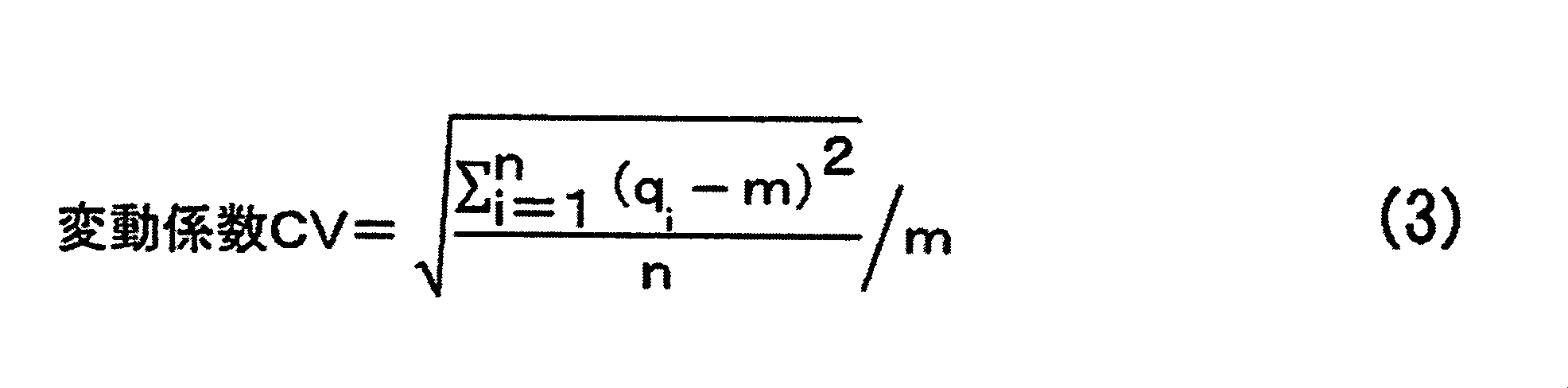
A commercially available apparatus can be used as an apparatus for measuring solid 7 Li-NMR. Under a room temperature environment, the measurement is performed by a single pulse method with a magic angle spinning speed of 14.5 kHz and an irradiation pulse width of 45 ° pulse. The measurement is set so that a sufficient waiting time is repeated between measurements. A 1 mol / L lithium chloride aqueous solution is used as a shift reference, and the shift position separately measured as an external standard is 0 ppm. When measuring a 1 mol / L lithium chloride aqueous solution, the sample is not rotated, and the irradiation pulse width is set to 45 ° pulse, and measurement is performed by a single pulse method.
For each of the first negative electrode active material layer provided on the first surface of the negative electrode current collector and the second negative electrode active material layer provided on the second surface of the negative electrode current collector, the negative electrode active material is obtained by the above method. A solid 7 Li-NMR spectrum of the layer is obtained. With respect to the solid 7 Li-NMR spectrum of each obtained negative electrode active material layer, the peak area is determined for the components in the range of −20 ppm to 60 ppm. Next, these peak areas are divided by the peak area of a 1 mol / L lithium chloride aqueous solution measured by making the sample height in the rotor for measurement the same as when measuring the negative electrode active material layer, and the negative electrode active used for the measurement is further divided. By dividing by the mass of the material layer, the amounts of lithium q 1 and q 2 can be calculated. In the present specification, the mass of the negative electrode active material layer is the mass of the negative electrode active material layer including lithium ions occluded in the negative electrode active material layer and / or a film or deposit contained in the negative electrode active material layer. .
The coefficient of variation CV is calculated by the following equation (3) using the obtained q 1 and q 2 .
負極活物質層は、負極活物質を含み、必要に応じて、導電性フィラー、結着剤、分散安定剤等の任意成分を含んでいてもよい。
本発明の第三の態様における負極活物質層は、負極集電体の表面及び裏面にそれぞれ形成された第1及び第2負極活物質層を含み、かつ第1及び第2負極活物質層中のリチウム量(q1,q2)は、互いに異なる。
第1及び第2負極活物質層は、それぞれリチウムイオンを吸蔵しており、かつ互いのリチウム量(q1,q2)が異なる限り、以下で説明される負極活物質、負極集電体及び製造方法を用いて形成されることができる。
[負極活物質]
前記負極活物質は、リチウムイオンを吸蔵・放出可能な物質を用いることができる。具体的には、炭素材料、チタン酸化物、ケイ素、ケイ素酸化物、ケイ素合金、ケイ素化合物、錫及び錫化合物等が例示される。好ましくは前記負極活物質の総量に対する前記炭素材料の含有率が50質量%以上であり、より好ましくは70質量%以上である。前記炭素材料の含有率が100質量%であることができるが、他の材料の併用による効果を良好に得る観点から、例えば、90質量%以下であることが好ましく、80質量%以下であってもよい。 [Negative electrode active material layer]
The negative electrode active material layer contains a negative electrode active material, and may contain optional components such as a conductive filler, a binder, and a dispersion stabilizer as necessary.
The negative electrode active material layer in the third aspect of the present invention includes first and second negative electrode active material layers formed on the front surface and the back surface of the negative electrode current collector, respectively, and in the first and second negative electrode active material layers The amounts of lithium (q 1 , q 2 ) are different from each other.
As long as the first and second negative electrode active material layers each occlude lithium ions and the amounts of lithium (q 1 , q 2 ) are different from each other, a negative electrode active material, a negative electrode current collector, and It can be formed using a manufacturing method.
[Negative electrode active material]
As the negative electrode active material, a material capable of inserting and extracting lithium ions can be used. Specific examples include carbon materials, titanium oxide, silicon, silicon oxide, silicon alloys, silicon compounds, tin and tin compounds. Preferably, the content of the carbon material with respect to the total amount of the negative electrode active material is 50% by mass or more, and more preferably 70% by mass or more. Although the content rate of the carbon material can be 100% by mass, it is preferably 90% by mass or less, for example, 80% by mass or less from the viewpoint of obtaining the effect of the combined use of other materials. Also good.
第一の形態としては、非水系リチウム蓄電素子を作製する前に、負極活物質に設計値として予め吸蔵させるリチウムイオンである。
第二の形態としては、非水系リチウム蓄電素子を作製し、出荷する際の負極活物質に吸蔵されているリチウムイオンである。
第三の形態としては、非水系リチウム蓄電素子をデバイスとして使用した後の負極活物質に吸蔵されているリチウムイオンである。
負極活物質にリチウムイオンをドープしておくことにより、得られる非水系リチウム蓄電素子の容量及び作動電圧を良好に制御することが可能となる。
前記炭素材料としては、例えば、難黒鉛化性炭素材料;易黒鉛化性炭素材料;カーボンブラック;カーボンナノ粒子;活性炭;人造黒鉛;天然黒鉛;黒鉛化メソフェーズカーボン小球体;黒鉛ウイスカ;ポリアセン系物質等のアモルファス炭素質材料;石油系のピッチ、石炭系のピッチ、メソカーボンマイクロビーズ、コークス、合成樹脂(例えばフェノール樹脂等)等の炭素前駆体を熱処理して得られる炭素質材料;フルフリルアルコール樹脂又はノボラック樹脂の熱分解物;フラーレン;カーボンナノフォーン;及びこれらの複合炭素材料を挙げることができる。 The negative electrode active material is preferably doped with lithium ions. In this specification, the lithium ion doped in the negative electrode active material mainly includes three forms.
The first form is lithium ions that are previously occluded as a design value in the negative electrode active material before producing a non-aqueous lithium electricity storage device.
The second form is lithium ions occluded in the negative electrode active material when a non-aqueous lithium electricity storage device is manufactured and shipped.
A third form is lithium ions occluded in the negative electrode active material after using the non-aqueous lithium electricity storage device as a device.
By doping lithium ions into the negative electrode active material, it is possible to satisfactorily control the capacity and operating voltage of the obtained non-aqueous lithium storage element.
Examples of the carbon material include non-graphitizable carbon materials; graphitizable carbon materials; carbon black; carbon nanoparticles; activated carbon; artificial graphite; natural graphite; graphitized mesophase carbon spherules; Amorphous carbonaceous materials such as petroleum-based pitch, coal-based pitch, mesocarbon microbeads, coke, carbonaceous materials obtained by heat treatment of carbon precursors such as synthetic resins (for example, phenol resins); furfuryl alcohol Examples include thermal decomposition products of resins or novolac resins; fullerenes; carbon nanophones; and composite carbon materials thereof.
前記ピッチ複合炭素材の好ましい例は、後述のピッチ複合炭素材料1a及び2aである。これらの内どちらかを選択して使用しても良く、又はこれらの双方を併用してもよい。
ピッチ複合炭素材料1aは、BET比表面積が100m2/g以上3000m2/g以下の炭素材料1種以上と石油系のピッチ又は石炭系のピッチとを共存させた状態で熱処理をして得ることができる。
前記炭素材料は、特に制限されるものではないが、活性炭やカーボンブラック、鋳型多孔質炭素、高比表面積黒鉛、カーボンナノ粒子等を好適に用いることができる。 Among these, from the viewpoint of lowering the resistance of the negative electrode, a pitch composite carbon material that can be obtained by heat treatment in the state where one or more carbon materials and a petroleum-based pitch or a coal-based pitch coexist is preferable. . Before the heat treatment, the carbon material and the pitch may be mixed at a temperature higher than the melting point of the pitch. The heat treatment temperature may be a temperature at which a component generated by volatilization or thermal decomposition of the pitch used becomes a carbonaceous material. As the atmosphere for performing the heat treatment, a non-oxidizing atmosphere is preferable.
Preferable examples of the pitch composite carbon material are pitch composite carbon materials 1a and 2a described later. Either of these may be selected and used, or both of them may be used in combination.
The pitch composite carbon material 1a is obtained by heat treatment in a state where at least one carbon material having a BET specific surface area of 100 m 2 / g or more and 3000 m 2 / g or less and a petroleum-based pitch or a coal-based pitch coexist. Can do.
The carbon material is not particularly limited, and activated carbon, carbon black, template porous carbon, high specific surface area graphite, carbon nanoparticles, and the like can be suitably used.
複合炭素材料1aは、BET比表面積が50m2/g以上3000m2/g以下の炭素材料1種以上を該基材として用いた該複合炭素材料である。該基材は、特に制限されるものではないが、活性炭やカーボンブラック、鋳型多孔質炭素、高比表面積黒鉛、カーボンナノ粒子等を好適に用いることができる。 -Composite carbon material 1a-
The composite carbon material 1a is the composite carbon material using one or more carbon materials having a BET specific surface area of 50 m 2 / g or more and 3000 m 2 / g or less as the base material. The substrate is not particularly limited, and activated carbon, carbon black, template porous carbon, high specific surface area graphite, carbon nanoparticles, and the like can be suitably used.
リチウムイオンをドープすることにより、負極電位が低くなる。従って、リチウムイオンがドープされた複合炭素材料1aを含む負極を正極と組み合わせた場合には、非水系リチウム蓄電素子の電圧が高くなるとともに、正極の利用容量が大きくなる。そのため、得られる非水系リチウム蓄電素子の容量及びエネルギー密度が高くなる。
該ドープ量が530mAh/g以上であれば、複合炭素材料1aにおけるリチウムイオンを一旦挿入したら脱離し得ない不可逆なサイトにもリチウムイオンが良好にドープされ、更に所望のリチウム量に対する複合炭素材料1aを低減することができる。そのため、負極膜厚を薄くすることが可能となり、高いエネルギー密度が得られる。ドープ量が多いほど負極電位が下がり、入出力特性、エネルギー密度、及び耐久性は向上する。
一方で、ドープ量が2,500mAh/g以下であれば、リチウム金属の析出等の副作用が発生するおそれがない。 The doping amount of lithium ions per unit mass of the composite carbon material 1a is preferably 530 mAh / g or more and 2500 mAh / g or less. More preferably, it is 620 mAh / g or more and 2,100 mAh / g or less, More preferably, it is 760 mAh / g or more and 1,700 mAh / g or less, Most preferably, it is 840 mAh / g or more and 1,500 mAh / g or less.
Doping lithium ions lowers the negative electrode potential. Therefore, when the negative electrode including the composite carbon material 1a doped with lithium ions is combined with the positive electrode, the voltage of the non-aqueous lithium storage element is increased and the utilization capacity of the positive electrode is increased. Therefore, the capacity and energy density of the obtained non-aqueous lithium storage element are increased.
When the doping amount is 530 mAh / g or more, lithium ions are well doped into irreversible sites that cannot be desorbed once the lithium ions in the composite carbon material 1a are inserted, and further, the composite carbon material 1a with respect to a desired amount of lithium. Can be reduced. Therefore, the negative electrode film thickness can be reduced, and a high energy density can be obtained. The larger the doping amount, the lower the negative electrode potential, and the input / output characteristics, energy density, and durability are improved.
On the other hand, when the doping amount is 2,500 mAh / g or less, there is no possibility that side effects such as precipitation of lithium metal occur.
複合炭素材料1aは、BJH法により算出した直径20Å以上500Å以下の細孔に由来するメソ孔量をVm1(cc/g)、MP法により算出した直径20Å未満の細孔に由来するマイクロ孔量をVm2(cc/g)とするとき、0.010≦Vm1≦0.300、0.001≦Vm2≦0.650であることが好ましい。
メソ孔量Vm1は、より好ましくは0.010≦Vm1≦0.225、さらに好ましくは0.010≦Vm1≦0.200である。マイクロ孔量Vm2は、より好ましくは0.001≦Vm2≦0.200、更に好ましくは0.001≦Vm2≦0.150、特に好ましくは0.001≦Vm2≦0.100である。 Hereinafter, as a preferable example of the composite carbon material 1a, the composite carbon material 1a using activated carbon as the base material will be described.
In the composite carbon material 1a, the amount of mesopores derived from pores having a diameter of 20 to 500 mm calculated by the BJH method is Vm1 (cc / g), and the amount of micropores derived from pores having a diameter of less than 20 mm calculated by the MP method. Is Vm2 (cc / g), it is preferable that 0.010 ≦ Vm1 ≦ 0.300 and 0.001 ≦ Vm2 ≦ 0.650.
The mesopore amount Vm1 is more preferably 0.010 ≦ Vm1 ≦ 0.225, and further preferably 0.010 ≦ Vm1 ≦ 0.200. The micropore amount Vm2 is more preferably 0.001 ≦ Vm2 ≦ 0.200, further preferably 0.001 ≦ Vm2 ≦ 0.150, and particularly preferably 0.001 ≦ Vm2 ≦ 0.100.
該活性炭においては、BJH法により算出した直径20Å以上500Å以下の細孔に由来するメソ孔量をV1(cc/g)、MP法により算出した直径20Å未満の細孔に由来するマイクロ孔量をV2(cc/g)としたとき、0.050≦V1≦0.500、0.005≦V2≦1.000、かつ、0.2≦V1/V2≦20.0であることが好ましい。 In order to obtain the composite carbon material 1a having the pore distribution range defined in the present embodiment, the pore distribution of the activated carbon used for the substrate is important.
In the activated carbon, the amount of mesopores derived from pores having a diameter of 20 to 500 mm calculated by the BJH method is V1 (cc / g), and the amount of micropores derived from pores having a diameter of less than 20 mm calculated by the MP method is used. When V2 (cc / g), 0.050 ≦ V1 ≦ 0.500, 0.005 ≦ V2 ≦ 1.000, and 0.2 ≦ V1 / V2 ≦ 20.0 are preferable.
上記の複合炭素材料1aを製造するための具体的方法としては、例えば、炭素質材料前駆体から揮発した炭化水素ガスを含む不活性雰囲気中で活性炭を熱処理し、気相で炭素質材料を被着させる方法が挙げられる。また、活性炭と炭素質材料前駆体とを予め混合し熱処理する方法、又は溶媒に溶解させた炭素質材料前駆体を活性炭に塗布して乾燥させた後に熱処理する方法も可能である。 The softening point of the pitch used is preferably 30 ° C. or higher and 250 ° C. or lower, and more preferably 60 ° C. or higher and 130 ° C. or lower. A pitch having a softening point of 30 ° C. or higher can be handled with high accuracy without any problem in handling properties. The pitch having a softening point of 250 ° C. or less contains a large amount of relatively low molecular weight compounds. Therefore, when the pitch is used, fine pores in the activated carbon can be deposited.
As a specific method for producing the composite carbon material 1a, for example, activated carbon is heat-treated in an inert atmosphere containing hydrocarbon gas volatilized from a carbonaceous material precursor, and the carbonaceous material is coated in a gas phase. The method of making it wear is mentioned. In addition, a method in which activated carbon and a carbonaceous material precursor are mixed in advance and heat-treated, or a method in which a carbonaceous material precursor dissolved in a solvent is applied to activated carbon and dried is then heat-treated.
複合炭素材料2aは、BET比表面積が0.5m2/g以上80m2/g以下の炭素材料1種以上を前記基材として用いた前記複合炭素材料である。該基材は、特に制限されるものではないが、天然黒鉛、人造黒鉛、低結晶黒鉛、ハードカーボン、ソフトカーボン、カーボンブラック等を好適に用いることができる。 -Composite carbon material 2a-
The composite carbon material 2a is the composite carbon material using one or more carbon materials having a BET specific surface area of 0.5 m 2 / g to 80 m 2 / g as the base material. The base material is not particularly limited, and natural graphite, artificial graphite, low crystal graphite, hard carbon, soft carbon, carbon black and the like can be suitably used.
リチウムイオンをドープすることにより、負極電位が低くなる。従って、リチウムイオンがドープされた複合炭素材料2aを含む負極を正極と組み合わせた場合には、非水系リチウム蓄電素子の電圧が高くなるとともに、正極の利用容量が大きくなる。そのため、得られる非水系リチウム蓄電素子の容量及びエネルギー密度が高くなる。
該ドープ量が50mAh/g以上であれば、複合炭素材料2aにおけるリチウムイオンを一旦挿入したら脱離し得ない不可逆なサイトにもリチウムイオンが良好にドープされるため、高いエネルギー密度が得られる。ドープ量が多いほど負極電位が下がり、入出力特性、エネルギー密度、及び耐久性は向上する。
一方で、ドープ量が700mAh/g以下であれば、リチウム金属の析出等の副作用が発生するおそれがない。 The doping amount of lithium ions per unit mass of the composite carbon material 2a is preferably 50 mAh / g or more and 700 mAh / g or less. More preferably, it is 70 mAh / g or more and 650 mAh / g or less, More preferably, it is 90 mAh / g or more and 600 mAh / g or less, Most preferably, it is 100 mAh / g or more and 550 mAh / g or less.
Doping lithium ions lowers the negative electrode potential. Therefore, when the negative electrode including the composite carbon material 2a doped with lithium ions is combined with the positive electrode, the voltage of the non-aqueous lithium storage element is increased and the utilization capacity of the positive electrode is increased. Therefore, the capacity and energy density of the obtained non-aqueous lithium storage element are increased.
When the doping amount is 50 mAh / g or more, lithium ions are favorably doped into irreversible sites that cannot be desorbed once the lithium ions in the composite carbon material 2a are inserted, so that a high energy density is obtained. The larger the doping amount, the lower the negative electrode potential, and the input / output characteristics, energy density, and durability are improved.
On the other hand, when the doping amount is 700 mAh / g or less, there is no possibility that side effects such as precipitation of lithium metal occur.
本発明における負極活物質層は、必要に応じて、負極活物質の他に、導電性フィラー、結着剤、分散安定剤等の任意成分を含んでいてもよい。
導電性フィラーの種類は特に制限されるものではないが、例えば、アセチレンブラック、ケッチェンブラック、気相成長炭素繊維等が例示される。導電性フィラーの使用量は、負極活物質100質量部に対して、好ましくは0質量部以上30質量部以下である。より好ましくは0質量部以上20質量部以下、さらに好ましくは0質量部以上15質量部以下である。
結着剤としては、特に制限されるものではないが、例えばPVdF(ポリフッ化ビニリデン)、PTFE(ポリテトラフルオロエチレン)、ポリイミド、ラテックス、スチレン-ブタジエン共重合体、フッ素ゴム、アクリル共重合体等を用いることができる。結着剤の使用量は、負極活物質100質量部に対して、好ましくは1質量部以上30質量部以下である。より好ましくは2質量部以上27質量部以下、さらに好ましくは3質量部以上25質量部以下である。結着剤の量が1質量%以上であれば、十分な電極強度が発現される。一方で結着剤の量が30質量部以下であれば、負極活物質へのリチウムイオンの出入りを阻害せず、高い入出力特性が発現される。
分散安定剤としては、特に制限されるものではないが、例えばPVP(ポリビニルピロリドン)、PVA(ポリビニルアルコール)、セルロース誘導体等を用いることができる。結着剤の使用量は、負極活物質100質量部に対して、好ましくは0質量部以上10質量部以下である。分散安定剤の量が10質量部以下であれば、負極活物質へのリチウムイオンの出入りを阻害せず、高い入出力特性が発現される。 (Other components of negative electrode active material layer)
The negative electrode active material layer in the present invention may contain optional components such as a conductive filler, a binder, and a dispersion stabilizer in addition to the negative electrode active material as necessary.
The type of the conductive filler is not particularly limited, and examples thereof include acetylene black, ketjen black, and vapor grown carbon fiber. The amount of the conductive filler used is preferably 0 to 30 parts by mass with respect to 100 parts by mass of the negative electrode active material. More preferably, it is 0 to 20 mass parts, More preferably, it is 0 to 15 mass parts.
The binder is not particularly limited. For example, PVdF (polyvinylidene fluoride), PTFE (polytetrafluoroethylene), polyimide, latex, styrene-butadiene copolymer, fluororubber, acrylic copolymer, etc. Can be used. The amount of the binder used is preferably 1 part by mass or more and 30 parts by mass or less with respect to 100 parts by mass of the negative electrode active material. More preferably, they are 2 mass parts or more and 27 mass parts or less, More preferably, they are 3 mass parts or more and 25 mass parts or less. When the amount of the binder is 1% by mass or more, sufficient electrode strength is exhibited. On the other hand, when the amount of the binder is 30 parts by mass or less, high input / output characteristics are exhibited without inhibiting lithium ions from entering and exiting the negative electrode active material.
Although it does not restrict | limit especially as a dispersion stabilizer, For example, PVP (polyvinyl pyrrolidone), PVA (polyvinyl alcohol), a cellulose derivative etc. can be used. The amount of the binder used is preferably 0 to 10 parts by mass with respect to 100 parts by mass of the negative electrode active material. When the amount of the dispersion stabilizer is 10 parts by mass or less, high input / output characteristics are exhibited without inhibiting lithium ions from entering and leaving the negative electrode active material.
本発明における負極集電体を構成する材料としては、電子伝導性が高く、電解液への溶出及び電解質又はイオンとの反応等による劣化がおこらない金属箔であることが好ましい。このような金属箔としては、特に制限はなく、例えば、アルミニウム箔、銅箔、ニッケル箔、ステンレス鋼箔等が挙げられる。本実施の形態の非水系リチウム蓄電素子における負極集電体としては、銅箔が好ましい。
前記金属箔は凹凸や貫通孔を持たない通常の金属箔でもよいし、エンボス加工、ケミカルエッチング、電解析出法、ブラスト加工等を施した凹凸を有する金属箔でもよいし、エキスパンドメタル、パンチングメタル、エッチング箔等の貫通孔を有する金属箔でもよい。本発明の第三、及び第四の態様における負極集電体は、凹凸若しくは貫通孔を持たない通常の金属箔、又は上記で定義された「無孔状の負極集電体」として使用される限り、エンボス加工、ケミカルエッチング、電解析出法、ブラスト加工等を施した凹凸を有する金属箔、若しくはエキスパンドメタル、パンチングメタル、エッチング箔等の貫通孔を有する金属箔でよい。
負極集電体の厚みは、負極の形状及び強度を十分に保持できれば特に制限はないが、例えば、1~100μmが好ましい。 [Negative electrode current collector]
The material constituting the negative electrode current collector in the present invention is preferably a metal foil that has high electron conductivity and does not deteriorate due to elution into the electrolytic solution and reaction with the electrolyte or ions. There is no restriction | limiting in particular as such metal foil, For example, aluminum foil, copper foil, nickel foil, stainless steel foil, etc. are mentioned. As the negative electrode current collector in the non-aqueous lithium electricity storage device of the present embodiment, a copper foil is preferable.
The metal foil may be a normal metal foil having no irregularities or through holes, or a metal foil having irregularities subjected to embossing, chemical etching, electrolytic deposition, blasting, etc., expanded metal, punching metal Alternatively, a metal foil having a through hole such as an etching foil may be used. The negative electrode current collector in the third and fourth aspects of the present invention is used as a normal metal foil having no irregularities or through-holes, or the “non-porous negative electrode current collector” defined above. As long as it is a metal foil having unevenness subjected to embossing, chemical etching, electrolytic deposition, blasting, or the like, or metal foil having through holes such as expanded metal, punching metal, etching foil or the like.
The thickness of the negative electrode current collector is not particularly limited as long as the shape and strength of the negative electrode can be sufficiently maintained, but for example, 1 to 100 μm is preferable.
負極は、負極集電体の片面上又は両面上に負極活物質層を有して成る。典型的な態様において負極活物質層は負極集電体に固着している。
負極は、既知のリチウムイオン電池、電気二重層キャパシタ等における電極の製造技術によって製造することが可能である。例えば、負極活物質を含む各種材料を水又は有機溶剤中に分散又は溶解してスラリー状の塗工液を調製し、この塗工液を負極集電体上の片面又は両面に塗工して塗膜を形成し、これを乾燥することにより負極を得ることが出来る。さらに得られた負極にプレスを施して、負極活物質層の膜厚や嵩密度を調整してもよい。或いは、溶剤を使用せずに、負極活物質を含む各種材料を乾式で混合し、得られた混合物をプレス成型した後、導電性接着剤を用いて負極集電体に貼り付ける方法も可能である。
塗工液の調製は、負極活物質を含む各種材料粉末の一部若しくは全部をドライブレンドし、次いで水又は有機溶媒、及び/又はそれらに結着剤や分散安定剤が溶解又は分散した液状又はスラリー状の物質を追加して調製してもよい。また、水又は有機溶媒に結着剤や分散安定剤が溶解又は分散した液状又はスラリー状の物質の中に、負極活物質を含む各種材料粉末を追加して調製してもよい。前記塗工液の調製は特に制限されるものではないが、好適にはホモディスパーや多軸分散機、プラネタリーミキサー、薄膜旋回型高速ミキサー等の分散機等を用いることが出来る。良好な分散状態の塗工液を得るためには、周速1m/s以上50m/s以下で分散することが好ましい。周速1m/s以上であれば、各種材料が良好に溶解又は分散するため好ましい。また、周速50m/s以下であれば、分散による熱やせん断力により各種材料が破壊されることなく、再凝集が生じることがないため好ましい。 [Manufacture of negative electrode]
The negative electrode has a negative electrode active material layer on one side or both sides of a negative electrode current collector. In a typical embodiment, the negative electrode active material layer is fixed to the negative electrode current collector.
The negative electrode can be manufactured by an electrode manufacturing technique in a known lithium ion battery, electric double layer capacitor or the like. For example, various materials including a negative electrode active material are dispersed or dissolved in water or an organic solvent to prepare a slurry-like coating liquid, and this coating liquid is applied to one or both surfaces on a negative electrode current collector. A negative electrode can be obtained by forming a coating film and drying it. Further, the obtained negative electrode may be pressed to adjust the film thickness and bulk density of the negative electrode active material layer. Alternatively, it is possible to mix various materials including the negative electrode active material dry without using a solvent, press the resulting mixture, and then apply it to the negative electrode current collector using a conductive adhesive. is there.
The coating liquid is prepared by dry blending a part or all of various material powders including the negative electrode active material, and then water or an organic solvent, and / or a liquid in which a binder or a dispersion stabilizer is dissolved or dispersed therein. A slurry-like substance may be added for preparation. Alternatively, various material powders containing a negative electrode active material may be added to a liquid or slurry substance in which a binder or dispersion stabilizer is dissolved or dispersed in water or an organic solvent. The preparation of the coating solution is not particularly limited, but preferably a disperser such as a homodisper, a multi-axis disperser, a planetary mixer, a thin film swirl type high speed mixer or the like can be used. In order to obtain a coating liquid in a good dispersion state, it is preferable to disperse at a peripheral speed of 1 m / s to 50 m / s. A peripheral speed of 1 m / s or more is preferable because various materials can be dissolved or dispersed well. A peripheral speed of 50 m / s or less is preferable because various materials are not destroyed by heat and shearing force due to dispersion and reaggregation does not occur.
また、前記塗工液のTI値(チクソトロピーインデックス値)は、1.1以上が好ましく、より好ましくは1.2以上、さらに好ましくは1.5以上である。TI値が1.1以上であれば、塗膜幅及び厚みが良好に制御できる。
前記塗膜の形成は特に制限されるものではないが、好適にはダイコーターやコンマコーター、ナイフコーター、グラビア塗工機等の塗工機を用いることが出来る。塗膜は単層塗工で形成してもよいし、多層塗工して形成してもよい。また、塗工速度は0.1m/分以上100m/分以下であることが好ましく、より好ましくは0.5m/分以上70m/分以下、さらに好ましくは1m/分以上50m/分以下である。塗工速度が0.1m/分以上であれば、安定に塗工出来る。他方、100m/分以下であれば、塗工精度を十分に確保できる。 The viscosity (ηb) of the coating solution is preferably 1,000 mPa · s or more and 20,000 mPa · s or less. More preferably, it is 1,500 mPa * s or more and 10,000 mPa * s or less, More preferably, it is 1,700 mPa * s or more and 5,000 mPa * s or less. When the viscosity (ηb) is 1,000 mPa · s or more, dripping at the time of coating film formation is suppressed, and the coating film width and thickness can be controlled well. Moreover, if it is 20,000 mPa * s or less, it can apply stably with little pressure loss in the flow path of the coating liquid at the time of using a coating machine, and can control to below desired film thickness.
The TI value (thixotropy index value) of the coating solution is preferably 1.1 or more, more preferably 1.2 or more, and further preferably 1.5 or more. When the TI value is 1.1 or more, the coating film width and thickness can be favorably controlled.
The formation of the coating film is not particularly limited, but preferably a coating machine such as a die coater, a comma coater, a knife coater, or a gravure coating machine can be used. The coating film may be formed by single layer coating or may be formed by multilayer coating. The coating speed is preferably from 0.1 m / min to 100 m / min, more preferably from 0.5 m / min to 70 m / min, still more preferably from 1 m / min to 50 m / min. If the coating speed is 0.1 m / min or more, stable coating can be achieved. On the other hand, if it is 100 m / min or less, sufficient coating accuracy can be secured.
結着剤の融点は、DSC(Differential Scanning Calorimetry、示差走査熱量分析)の吸熱ピーク位置で求めることができる。例えば、パーキンエルマー社製の示差走査熱量計「DSC7」を用いて、試料樹脂10mgを測定セルにセットし、窒素ガス雰囲気中で、温度30℃から10℃/分の昇温速度で250℃まで昇温し、昇温過程における吸熱ピーク温度が融点となる。
また、プレス圧力、隙間、速度、プレス部の表面温度の条件を変えながら複数回プレスを実施してもよい。 Although the press of the negative electrode is not particularly limited, a press such as a hydraulic press or a vacuum press can be preferably used. The film thickness, bulk density, and electrode strength of the negative electrode active material layer can be adjusted by the press pressure, gap, and surface temperature of the press part described later. The pressing pressure is preferably 0.5 kN / cm or more and 20 kN / cm or less, more preferably 1 kN / cm or more and 10 kN / cm or less, and further preferably 2 kN / cm or more and 7 kN / cm or less. If the pressing pressure is 0.5 kN / cm or more, the electrode strength can be sufficiently increased. On the other hand, if it is 20 kN / cm or less, the negative electrode is not bent or wrinkled, and can be adjusted to the desired negative electrode active material layer thickness and bulk density. In addition, the gap between the press rolls can be set to an arbitrary value according to the negative electrode film thickness after drying so as to be a desired film thickness or bulk density of the negative electrode active material layer. Furthermore, the press speed can be set to an arbitrary speed at which the negative electrode is not bent or wrinkled. Moreover, the surface temperature of a press part may be room temperature, and may be heated if necessary. The lower limit of the surface temperature of the press part in the case of heating is preferably the melting point minus 60 ° C. or more of the binder used, more preferably 45 ° C. or more, and further preferably 30 ° C. or more. On the other hand, the upper limit of the surface temperature of the press part in the case of heating is preferably the melting point of the binder used plus 50 ° C. or less, more preferably 30 ° C. or less, and further preferably 20 ° C. or less. For example, when PVdF (polyvinylidene fluoride: melting point 150 ° C.) is used as the binder, it is preferably heated to 90 ° C. or higher and 200 ° C. or lower, more preferably 105 ° C. or higher and 180 ° C. or lower, and even more preferably 120 ° C. or higher. Heating to 170 ° C. or lower. When a styrene-butadiene copolymer (melting point 100 ° C.) is used as the binder, it is preferably heated to 40 ° C. or higher and 150 ° C. or lower, more preferably 55 ° C. or higher and 130 ° C. or lower, and still more preferably 70 ° C. It is heating up to 120 ° C. or higher.
The melting point of the binder can be determined at the endothermic peak position of DSC (Differential Scanning Calorimetry). For example, using a differential scanning calorimeter “DSC7” manufactured by PerkinElmer Co., Ltd., 10 mg of sample resin is set in a measurement cell, and the temperature is increased from 30 ° C. to 250 ° C. at a temperature increase rate of 10 ° C./min in a nitrogen gas atmosphere. The temperature is raised, and the endothermic peak temperature in the temperature raising process becomes the melting point.
Moreover, you may press several times, changing the conditions of press pressure, a clearance gap, speed | rate, and the surface temperature of a press part.
測定に用いるサンプルは、非水系リチウム蓄電素子に組み込まれていない負極(以下、「使用前負極」ともいう。)を用いてもよく、非水系リチウム蓄電素子に組み込まれている負極(以下、「使用後負極」ともいう。)を用いてもよい。
非水系リチウム蓄電素子に組み込まれている負極を測定サンプルに用いる場合には、測定サンプルの前処理として、例えば以下の方法を用いることが好ましい。
先ず、アルゴン等の不活性雰囲気下で非水系リチウム蓄電素子を解体し、負極を取り出す。取り出した負極を鎖状カーボネート(例えばメチルエチルカーボネート、ジメチルカーボネート等)に浸漬し、非水系電解液やリチウム塩等を取り除いて風乾する。次いで、例えば以下の(1)、(2)、又は(3)の方法を用いることが好ましい。
(1)得られる負極をメタノールとイソプロパノールとから成る混合溶媒に浸漬して負極活物質に吸蔵したリチウムイオンを失活させて、風乾する。次いで、真空乾燥等を用いて得られる負極に含まれる鎖状カーボネートや有機溶媒等を取り除くことにより、測定サンプルを得ることができる。
(2)アルゴン等の不活性雰囲気下で、得られる負極を作用極に、金属リチウムを対極及び参照極に用い、これらを非水系電解液に浸して電気化学セルを作製する。得られる電気化学セルについて充放電機等を用いて、負極電位(vs.Li/Li+)が1.5V~3.5Vの範囲になるように調整する。次いで、アルゴン等の不活性雰囲気下で電気化学セルから負極を取り出し、これを鎖状カーボネートに浸漬し、非水系電解液やリチウム塩等を取り除いて風乾する。次いで、真空乾燥等を用いて得られる負極に含まれる鎖状カーボネート等を取り除くことにより、測定サンプルを得ることができる。
(3)上記で得られる負極をそのまま測定サンプルとして用いることができる。 In this specification, the BET specific surface area per unit volume of the negative electrode active material layer can be calculated by the following method.
The sample used for the measurement may be a negative electrode (hereinafter also referred to as “a negative electrode before use”) that is not incorporated in a non-aqueous lithium storage element, or a negative electrode that is incorporated in a non-aqueous lithium storage element (hereinafter “ Also referred to as “post-use negative electrode”.
When the negative electrode incorporated in the non-aqueous lithium storage element is used as a measurement sample, it is preferable to use, for example, the following method as a pretreatment of the measurement sample.
First, the nonaqueous lithium storage element is disassembled under an inert atmosphere such as argon, and the negative electrode is taken out. The taken-out negative electrode is immersed in chain carbonate (for example, methyl ethyl carbonate, dimethyl carbonate, etc.), non-aqueous electrolyte solution, lithium salt, etc. are removed and air-dried. Next, for example, the following method (1), (2), or (3) is preferably used.
(1) The obtained negative electrode is immersed in a mixed solvent of methanol and isopropanol to deactivate lithium ions occluded in the negative electrode active material, and air-dried. Subsequently, a measurement sample can be obtained by removing the chain carbonate, the organic solvent, and the like contained in the negative electrode obtained by vacuum drying or the like.
(2) Under an inert atmosphere such as argon, the obtained negative electrode is used as a working electrode, metallic lithium is used as a counter electrode and a reference electrode, and these are immersed in a non-aqueous electrolyte to produce an electrochemical cell. The obtained electrochemical cell is adjusted using a charging / discharging machine or the like so that the negative electrode potential (vs. Li / Li + ) is in the range of 1.5V to 3.5V. Next, the negative electrode is taken out from the electrochemical cell under an inert atmosphere such as argon, soaked in a chain carbonate, removed from the non-aqueous electrolyte, lithium salt, etc., and air-dried. Next, a measurement sample can be obtained by removing the chain carbonate and the like contained in the negative electrode obtained by vacuum drying or the like.
(3) The negative electrode obtained above can be used as a measurement sample as it is.
上記で得られる測定サンプルを用いて、窒素又はアルゴンを吸着質として、吸脱着の等温線の測定を行う。ここで得られる吸着側の等温線を用いて、BET多点法又はBET1点法によりBET比表面積を算出し、これをVanoで除すことにより負極活物質層単位体積当たりのBET比表面積を算出する。 As shown in FIG. 2, the volume Vano (cc) of the negative electrode active material layer is measured for the measurement sample obtained above. When the horizontal plane with respect to the stacking direction of the negative electrode current collector and the negative electrode active material layer is a cross-section, and the plane perpendicular to the horizontal plane is a plane, the geometric area of the plane of the measurement sample is Sano , and the above-described negative electrode active material layer when was the t ano total film thickness, the volume of the negative electrode active material layer can be calculated by V ano = S ano × t ano .
Using the measurement sample obtained above, adsorption and desorption isotherms are measured using nitrogen or argon as an adsorbate. Using suction side of the isotherm obtained here, BET by multipoint method or BET1 point method to calculate the BET specific surface area, a BET specific surface area per anode active material layer per unit volume by dividing this in V ano calculate.
先ず、本実施形態係る負極活物質層をエチルメチルカーボネート又はジメチルカーボネートで洗浄し風乾した後、メタノール及びイソプロパノールから成る混合溶媒により抽出した抽出液と、抽出後の負極活物質層とを得る。この抽出は、典型的にはArボックス内にて、環境温度23℃で行われる。
上記のようにして得られた抽出液と、抽出後の負極活物質層とに含まれるリチウム量を、それぞれ、例えばICP-MS(誘導結合プラズマ質量分析計)等を用いて定量し、その合計を求めることによって、負極活物質におけるリチウムイオンのドープ量を知ることができる。得られた値を抽出に供した負極活物質量で割り付けて、リチウムイオンのドープ量(mAh/g)を算出すればよい。 The doping amount (mAh / g) of the lithium ion of the negative electrode active material in the non-aqueous lithium electricity storage device at the time of shipment and after use according to the present embodiment can be known, for example, as follows.
First, the negative electrode active material layer according to the present embodiment is washed with ethyl methyl carbonate or dimethyl carbonate and air-dried, and then an extract extracted with a mixed solvent composed of methanol and isopropanol and a negative electrode active material layer after extraction are obtained. This extraction is typically performed at an ambient temperature of 23 ° C. in an Ar box.
The amount of lithium contained in the extract obtained as described above and the negative electrode active material layer after extraction is quantified using, for example, ICP-MS (inductively coupled plasma mass spectrometer), and the total amount Thus, the lithium ion doping amount in the negative electrode active material can be known. The obtained value may be allocated by the amount of the negative electrode active material used for extraction to calculate the lithium ion dope amount (mAh / g).
正極前駆体及び負極は、セパレータを介して積層又は捲回され、正極前駆体、負極及びセパレータを有する電極積層体、又は電極捲回体が形成される。
前記セパレータとしては、リチウムイオン二次電池に用いられるポリエチレン製の微多孔膜若しくはポリプロピレン製の微多孔膜、又は電気二重層キャパシタで用いられるセルロース製の不織紙等を用いることができる。これらのセパレータの片面または両面に、有機または無機の微粒子からなる膜が積層されていてもよい。また、セパレータの内部に有機または無機の微粒子が含まれていてもよい。
セパレータの厚みは5μm以上35μm以下が好ましい。5μm以上の厚みとすることにより、内部のマイクロショートによる自己放電が小さくなる傾向があるため好ましい。他方、35μm以下の厚みとすることにより、蓄電素子の出力特性が高くなる傾向があるため好ましい。
また、有機または無機の微粒子からなる膜は、1μm以上10μm以下が好ましい。1μm以上の厚みとすることにより、内部のマイクロショートによる自己放電が小さくなる傾向があるため好ましい。他方、10μm以下の厚みとすることにより、蓄電素子の出力特性が高くなる傾向があるため好ましい。 <Separator>
The positive electrode precursor and the negative electrode are laminated or wound via a separator to form an electrode laminate having a positive electrode precursor, a negative electrode and a separator, or an electrode winding body.
As the separator, a polyethylene microporous film or a polypropylene microporous film used in a lithium ion secondary battery, a cellulose nonwoven paper used in an electric double layer capacitor, or the like can be used. A film made of organic or inorganic fine particles may be laminated on one side or both sides of these separators. Further, organic or inorganic fine particles may be contained inside the separator.
The thickness of the separator is preferably 5 μm or more and 35 μm or less. A thickness of 5 μm or more is preferable because self-discharge due to internal micro-shorts tends to be small. On the other hand, a thickness of 35 μm or less is preferable because the output characteristics of the electricity storage element tend to be high.
The film made of organic or inorganic fine particles is preferably 1 μm or more and 10 μm or less. A thickness of 1 μm or more is preferable because self-discharge due to internal micro-shorts tends to be small. On the other hand, the thickness of 10 μm or less is preferable because the output characteristics of the electricity storage element tend to be high.
外装体としては、金属缶、ラミネートフィルム等を使用できる。
前記金属缶としては、アルミニウム製のものが好ましい。
前記ラミネートフィルムとしては、金属箔と樹脂フィルムとを積層したフィルムが好ましく、外層樹脂フィルム/金属箔/内装樹脂フィルムから成る3層構成のものが例示される。外層樹脂フィルムは、接触等により金属箔が損傷を受けることを防止するためのものであり、ナイロン又はポリエステル等の樹脂が好適に使用できる。金属箔は水分及びガスの透過を防ぐためのものであり、銅、アルミニウム、ステンレス等の箔が好適に使用できる。また、内装樹脂フィルムは、内部に収納する電解液から金属箔を保護するとともに、外装体のヒートシール時に溶融封口させるためのものであり、ポリオレフィン、酸変成ポリオレフィン等が好適に使用できる。 <Exterior body>
A metal can, a laminate film, or the like can be used as the exterior body.
The metal can is preferably made of aluminum.
As the laminate film, a film in which a metal foil and a resin film are laminated is preferable, and an example of a three-layer structure composed of an outer layer resin film / metal foil / interior resin film is exemplified. The outer layer resin film is for preventing the metal foil from being damaged by contact or the like, and a resin such as nylon or polyester can be suitably used. The metal foil is for preventing the permeation of moisture and gas, and foils of copper, aluminum, stainless steel and the like can be suitably used. The interior resin film protects the metal foil from the electrolyte contained in the interior, and melts and seals the exterior body during heat sealing. Polyolefin, acid-modified polyolefin, and the like can be suitably used.
本実施形態における電解液は非水系電解液である。すなわちこの電解液は、後述する非水溶媒を含む。前記非水系電解液は、前記非水系電解液の総量を基準として、0.5mol/L以上のリチウム塩を含有する。すなわち、非水系電解液は、リチウムイオンを電解質として含む。
本実施形態における非水系電解液は、リチウム塩として、例えば、LiN(SO2F)2、LiN(SO2CF3)2、LiN(SO2C2F5)2、LiN(SO2CF3)(SO2C2F5)、LiN(SO2CF3)(SO2C2F4H)、LiC(SO2F)3、LiC(SO2CF3)3、LiC(SO2C2F5)3、LiCF3SO3、LiC4F9SO3、LiPF6、LiBF4等を単独で用いることができ、2種以上を混合して用いてもよい。高い伝導度を発現できることから、LiPF6及び/又はLiN(SO2F)2を含むことが好ましい。
本実施形態に係る非水系電解液には少なくとも1種以上のリチウム塩を含有していればよく、リチウム塩の他にナトリウム塩、カリウム塩、ルビジウム塩、セシウム塩から選ばれるアルカリ金属塩、又は、ベリリウム塩、マグネシウム塩、カルシウム塩、ストロンチウム塩、バリウム塩から選ばれるアルカリ土類金属塩を含有していてもよい。
非水系電解液中にリチウム以外の上記アルカリ金属塩を含有する場合、リチウムイオンよりもストークス半径の小さなナトリウムイオン、カリウムイオン、ルビジウムイオン、セシウムイオンが高いイオン伝導度を有するために、非水系リチウム蓄電素子を低抵抗化することができる。非水系電解液中にリチウム以外の上記アルカリ土類金属塩を含有する場合、ベリリウムイオン、マグネシウムイオン、カルシウムイオン、ストロンチウムイオン、バリウムイオンが2価の陽イオンであるために非水系リチウム蓄電素子を高容量化することができる。
リチウム塩以外の上記アルカリ金属塩、又は/及びアルカリ土類金属塩を非水系電解液中に含有させる方法は特に限定されないが、非水系電解液中に予めリチウム塩と、リチウム塩以外のアルカリ金属塩又は/及びアルカリ土類金属塩を溶解することもできるし、正極前駆体中に下記式におけるMをNa、K、Rb、及びCsから選ばれる1種以上として、
M2CO3等の炭酸塩、
M2O等の酸化物、
MOH等の水酸化物、
MFやMCl等のハロゲン化物、
M2(CO2)2等の蓚酸塩、
RCOOM(式中、RはH、アルキル基、又はアリール基である)等のカルボン酸塩、
又は/及び、BeCO3、MgCO3、CaCO3、SrCO3、又はBaCO3から選ばれるアルカリ土類金属炭酸塩、並びにアルカリ土類金属酸化物、アルカリ土類金属水酸化物、アルカリ土類金属ハロゲン化物、アルカリ土類金属シュウ酸塩、及びアルカリ土類金属カルボン酸塩を1種以上含有させ、後述のリチウムドープ工程にて分解する方法等が挙げられる。 <Non-aqueous electrolyte>
The electrolytic solution in the present embodiment is a non-aqueous electrolytic solution. That is, this electrolytic solution contains a nonaqueous solvent described later. The nonaqueous electrolytic solution contains 0.5 mol / L or more lithium salt based on the total amount of the nonaqueous electrolytic solution. That is, the non-aqueous electrolyte contains lithium ions as an electrolyte.
The non-aqueous electrolyte solution in this embodiment is, for example, LiN (SO 2 F) 2 , LiN (SO 2 CF 3 ) 2 , LiN (SO 2 C 2 F 5 ) 2 , LiN (SO 2 CF 3 ) as a lithium salt. ) (SO 2 C 2 F 5 ), LiN (SO 2 CF 3 ) (SO 2 C 2 F 4 H), LiC (SO 2 F) 3 , LiC (SO 2 CF 3 ) 3 , LiC (SO 2 C 2 F 5 ) 3 , LiCF 3 SO 3 , LiC 4 F 9 SO 3 , LiPF 6 , LiBF 4 and the like can be used alone, or two or more of them may be used in combination. LiPF 6 and / or LiN (SO 2 F) 2 are preferably included because high conductivity can be exhibited.
The non-aqueous electrolyte solution according to the present embodiment only needs to contain at least one lithium salt, and in addition to the lithium salt, an alkali metal salt selected from sodium salt, potassium salt, rubidium salt, cesium salt, or An alkaline earth metal salt selected from beryllium salt, magnesium salt, calcium salt, strontium salt and barium salt may be contained.
When the alkali metal salt other than lithium is contained in the non-aqueous electrolyte, the non-aqueous lithium has a high ion conductivity because sodium ions, potassium ions, rubidium ions, and cesium ions having a smaller Stokes radius than lithium ions. The resistance of the power storage element can be reduced. When the alkaline earth metal salt other than lithium is contained in the non-aqueous electrolyte, beryllium ion, magnesium ion, calcium ion, strontium ion, and barium ion are divalent cations. The capacity can be increased.
The method for containing the alkali metal salt or / and alkaline earth metal salt other than the lithium salt in the non-aqueous electrolyte solution is not particularly limited, but the lithium salt and the alkali metal other than the lithium salt are previously contained in the non-aqueous electrolyte solution. The salt or / and alkaline earth metal salt can also be dissolved, and M in the following formula in the positive electrode precursor is one or more selected from Na, K, Rb, and Cs,
Carbonates such as M 2 CO 3 ,
Oxides such as M 2 O,
Hydroxides such as MOH,
Halides such as MF and MCl,
Oxalates such as M 2 (CO 2 ) 2 ,
Carboxylates such as RCOOM (wherein R is H, an alkyl group, or an aryl group),
And / or, BeCO 3, MgCO 3, CaCO 3,
非水系電解液中にリチウム塩以外の上記アルカリ金属塩、又は/及びアルカリ土類金属塩を含有する場合、それらの塩濃度の合計値が0.5mol/L以上であることが好ましく、0.5~2.0mol/Lの範囲であることがより好ましい。
本実施形態における非水系電解液は、非水溶媒として、好ましくは、環状カーボネート及び鎖状カーボネートを含有する。非水系電解液が環状カーボネート及び鎖状カーボネートを含有することは、所望の濃度のリチウム塩を溶解させる点、及び高いリチウムイオン伝導度を発現する点で有利である。環状カーボネートとしては、例えば、エチレンカーボネート、プロピレンカーボネート、ブチレンカーボネート等に代表されるアルキレンカーボネート化合物が挙げられる。アルキレンカーボネート化合物は、典型的には非置換である。鎖状カーボネートとしては、ジメチルカーボネート、ジエチルカーボネート、エチルメチルカーボネート、ジプロピルカーボネート、ジブチルカーボネート等に代表されるジアルキルカーボネート化合物が挙げられる。ジアルキルカーボネート化合物は典型的には非置換である。 The lithium salt concentration in the non-aqueous electrolyte is preferably 0.5 mol / L or more, and more preferably in the range of 0.5 to 2.0 mol / L. If the lithium salt concentration is 0.5 mol / L or more, anions are sufficiently present, so that the capacity of the energy storage device can be sufficiently increased. Further, when the lithium salt concentration is 2.0 mol / L or less, it is possible to prevent undissolved lithium salt from precipitating in the non-aqueous electrolyte and preventing the viscosity of the electrolyte from becoming too high, resulting in a decrease in conductivity. And output characteristics are not deteriorated.
When the alkali metal salt or / and alkaline earth metal salt other than the lithium salt is contained in the nonaqueous electrolytic solution, the total value of the salt concentrations is preferably 0.5 mol / L or more. A range of 5 to 2.0 mol / L is more preferable.
The nonaqueous electrolytic solution in the present embodiment preferably contains a cyclic carbonate and a chain carbonate as a nonaqueous solvent. The nonaqueous electrolytic solution containing a cyclic carbonate and a chain carbonate is advantageous in that a lithium salt having a desired concentration is dissolved and a high lithium ion conductivity is exhibited. Examples of the cyclic carbonate include alkylene carbonate compounds represented by ethylene carbonate, propylene carbonate, butylene carbonate, and the like. The alkylene carbonate compound is typically unsubstituted. Examples of the chain carbonate include dialkyl carbonate compounds represented by dimethyl carbonate, diethyl carbonate, ethyl methyl carbonate, dipropyl carbonate, dibutyl carbonate and the like. The dialkyl carbonate compound is typically unsubstituted.
本実施形態における非水系電解液は、更に添加剤を含有していてもよい。添加剤としては、特に制限されないが、例えば、スルトン化合物、環状ホスファゼン、非環状含フッ素エーテル、含フッ素環状カーボネート、環状炭酸エステル、環状カルボン酸エステル、及び環状酸無水物等を単独で用いることができ、また2種以上を混合して用いてもよい。
本実施形態では、抵抗への悪影響の少なさの観点、及び非水系電解液の高温における分解を抑制してガス発生を抑えるという観点から、飽和環状スルトン化合物としては、1,3-プロパンスルトン、2,4-ブタンスルトン、1,4-ブタンスルトン、1,3-ブタンスルトン又は2,4-ペンタンスルトンが好ましく、不飽和環状スルトン化合物としては、1,3-プロペンスルトン又は1,4-ブテンスルトンが好ましく、その他のスルトン化合物としては、メチレンビス(ベンゼンスルホン酸)、メチレンビス(フェニルメタンスルホン酸)、メチレンビス(エタンスルホン酸)、メチレンビス(2,4,6,トリメチルベンゼンスルホン酸)、及びメチレンビス(2-トリフルオロメチルベンゼンスルホン酸)を挙げることができ、これらのうちから選択される少なくとも1種以上を選択することが好ましい。 The total content of the cyclic carbonate and the chain carbonate is preferably 50% by mass or more, more preferably 65% by mass or more, preferably 95% by mass or less, more preferably 90% by mass, based on the total amount of the non-aqueous electrolyte solution. % Or less. When the total content is 50% by mass or more, a lithium salt having a desired concentration can be dissolved, and high lithium ion conductivity can be expressed. If the said total concentration is 95 mass% or less, electrolyte solution can further contain the additive mentioned later.
The non-aqueous electrolyte solution in the present embodiment may further contain an additive. Although it does not restrict | limit especially as an additive, For example, using a sultone compound, cyclic phosphazene, acyclic fluorine-containing ether, a fluorine-containing cyclic carbonate, cyclic carbonate ester, cyclic carboxylate ester, cyclic acid anhydride, etc. independently. Two or more kinds may be mixed and used.
In the present embodiment, from the viewpoint of less adverse effects on resistance, and from the viewpoint of suppressing gas generation by suppressing decomposition of the non-aqueous electrolyte at a high temperature, the saturated cyclic sultone compound includes 1,3-propane sultone, 2,4-butane sultone, 1,4-butane sultone, 1,3-butane sultone or 2,4-pentane sultone is preferable, and as the unsaturated cyclic sultone compound, 1,3-propene sultone or 1,4-butene sultone is preferable, Other sultone compounds include methylene bis (benzene sulfonic acid), methylene bis (phenylmethane sulfonic acid), methylene bis (ethane sulfonic acid), methylene bis (2,4,6, trimethylbenzene sulfonic acid), and methylene bis (2-trifluoro). Methylbenzenesulfonic acid) It is preferable to select at least one or more selected from these.
前記環状ホスファゼンとしては、例えばエトキシペンタフルオロシクロトリホスファゼン、ジエトキシテトラフルオロシクロトリホスファゼン、フェノキシペンタフルオロシクロトリホスファゼン等を挙げることができ、これらのうちから選択される1種以上が好ましい。 The total content of sultone compounds in the non-aqueous electrolyte solution of the non-aqueous lithium battery element according to this embodiment is preferably 0.1% by mass to 15% by mass based on the total amount of the non-aqueous electrolyte solution. If the total content of sultone compounds in the non-aqueous electrolyte solution is 0.1% by mass or more, it is possible to suppress gas generation by suppressing decomposition of the electrolyte solution at a high temperature. On the other hand, if the total content is 15% by mass or less, a decrease in the ionic conductivity of the electrolytic solution can be suppressed, and high input / output characteristics can be maintained. Further, the content of the sultone compound present in the non-aqueous electrolyte solution of the non-aqueous lithium storage element is preferably 0.5% by mass or more and 10% by mass or less from the viewpoint of achieving both high input / output characteristics and durability. More preferably, it is 1 mass% or more and 5 mass% or less.
Examples of the cyclic phosphazene include ethoxypentafluorocyclotriphosphazene, diethoxytetrafluorocyclotriphosphazene, phenoxypentafluorocyclotriphosphazene, and the like, and one or more selected from these are preferable.
尚、これらの環状ホスファゼンは、単独で用いてもよく、又は2種以上を混合して用いてもよい。
非環状含フッ素エーテルとしては、例えばHCF2CF2OCH2CF2CF2H、CF3CFHCF2OCH2CF2CF2H、HCF2CF2CH2OCH2CF2CF2H、CF3CFHCF2OCH2CF2CFHCF3等が挙げられ、中でも、電気化学的安定性の観点から、HCF2CF2OCH2CF2CF2Hが好ましい。 The content of cyclic phosphazene in the non-aqueous electrolyte is preferably 0.5% by mass to 20% by mass based on the total amount of the non-aqueous electrolyte. If this value is 0.5% by mass or more, it is possible to suppress gas generation by suppressing decomposition of the electrolyte solution at high temperatures. On the other hand, if this value is 20% by mass or less, a decrease in the ionic conductivity of the electrolytic solution can be suppressed, and high input / output characteristics can be maintained. For the above reasons, the content of cyclic phosphazene is preferably 2% by mass or more and 15% by mass or less, more preferably 4% by mass or more and 12% by mass or less.
These cyclic phosphazenes may be used alone or in combination of two or more.
Examples of the acyclic fluorine-containing ether include HCF 2 CF 2 OCH 2 CF 2 CF 2 H, CF 3 CFHCF 2 OCH 2 CF 2 CF 2 H, HCF 2 CF 2 CH 2 OCH 2 CF 2 CF 2 H, CF 3 CFHCF 2 OCH 2 CF 2 CFHCF 3 and the like are mentioned, and among them, HCF 2 CF 2 OCH 2 CF 2 CF 2 H is preferable from the viewpoint of electrochemical stability.
尚、前記の非環状含フッ素エーテルは、単独で使用しても、2種以上を混合して使用してもよい。
含フッ素環状カーボネートについては、他の非水溶媒との相溶性の観点から、フルオロエチレンカーボネート(FEC)及びジフルオロエチレンカーボネート(dFEC)から選択して使用されることが好ましい。
フッ素原子を含有する環状カーボネートの含有量は、前記非水系電解液の総量を基準として、0.5質量%以上10質量%以下が好ましく、1質量%以上5質量%以下であることが更に好ましい。フッ素原子を含有する環状カーボネートの含有量が0.5質量%以上であれば、負極上に良質な被膜を形成することができ、負極上における電解液の還元分解を抑制することによって、高温における耐久性が高い蓄電素子が得られる。他方、フッ素原子を含有する環状カーボネートの含有量が10質量%以下であれば、電解質塩の溶解度が良好に保たれ、かつ、非水系電解液のイオン伝導度を高く維持することができ、従って高度の入出力特性を発現することが可能となる。
尚、前記のフッ素原子を含有する環状カーボネートは、単独で使用しても、2種以上を混合して使用してもよい。 The content of the non-cyclic fluorine-containing ether is preferably 0.5% by mass or more and 15% by mass or less, more preferably 1% by mass or more and 10% by mass or less, based on the total amount of the non-aqueous electrolyte solution. When the content of the non-cyclic fluorine-containing ether is 0.5% by mass or more, the stability of the non-aqueous electrolyte solution against oxidative decomposition is improved, and an electricity storage device having high durability at high temperatures can be obtained. On the other hand, if the content of the non-cyclic fluorine-containing ether is 15% by mass or less, the solubility of the electrolyte salt can be kept good, and the ionic conductivity of the non-aqueous electrolyte can be kept high. It is possible to develop input / output characteristics.
The acyclic fluorine-containing ether may be used alone or in combination of two or more.
The fluorine-containing cyclic carbonate is preferably selected from fluoroethylene carbonate (FEC) and difluoroethylene carbonate (dFEC) from the viewpoint of compatibility with other nonaqueous solvents.
The content of the cyclic carbonate containing a fluorine atom is preferably 0.5% by mass or more and 10% by mass or less, more preferably 1% by mass or more and 5% by mass or less, based on the total amount of the non-aqueous electrolyte solution. . If the content of the cyclic carbonate containing a fluorine atom is 0.5% by mass or more, a good-quality film can be formed on the negative electrode, and by suppressing the reductive decomposition of the electrolytic solution on the negative electrode, A highly durable power storage element can be obtained. On the other hand, if the content of the cyclic carbonate containing a fluorine atom is 10% by mass or less, the solubility of the electrolyte salt can be kept good, and the ionic conductivity of the non-aqueous electrolyte can be kept high. It is possible to develop advanced input / output characteristics.
In addition, the said cyclic carbonate containing a fluorine atom may be used individually, or 2 or more types may be mixed and used for it.
環状炭酸エステルの含有量は、前記非水系電解液の総量を基準として、0.5質量%以上10質量%以下が好ましく、1質量%以上5質量%以下であることが更に好ましい。環状炭酸エステルの含有量が0.5質量%以上であれば、負極上の良質な被膜を形成することができ、負極上での電解液の還元分解を抑制することにより、高温における耐久性が高い蓄電素子が得られる。一方、環状炭酸エステルの含有量が10質量%以下であれば、電解質塩の溶解度が良好に保たれ、かつ非水系電解液のイオン伝導度を高く維持することができ、従って高度の入出力特性を発現することが可能となる。
環状カルボン酸エステルとしては、例えばガンマブチロラクトン、ガンマバレロラクトン、ガンマカプロラクトン、イプシロンカプロラクトン等を挙げることができ、これらのうちから選択される1種以上を使用することが好ましい。中でも、ガンマブチロラクトンが、リチウムイオン解離度の向上に由来する電池特性向上の点から、特に好ましい。 For the cyclic carbonate, vinylene carbonate is preferred.
The content of the cyclic carbonate is preferably 0.5% by mass or more and 10% by mass or less, more preferably 1% by mass or more and 5% by mass or less, based on the total amount of the nonaqueous electrolytic solution. If the content of the cyclic carbonate is 0.5% by mass or more, a good-quality film on the negative electrode can be formed, and by suppressing the reductive decomposition of the electrolyte solution on the negative electrode, durability at high temperatures can be achieved. A high power storage element can be obtained. On the other hand, if the content of the cyclic carbonate is 10% by mass or less, the solubility of the electrolyte salt can be kept good, and the ionic conductivity of the non-aqueous electrolyte can be kept high, so that high input / output characteristics are obtained. Can be expressed.
Examples of the cyclic carboxylic acid ester include gamma butyrolactone, gamma valerolactone, gamma caprolactone, epsilon caprolactone, and the like, and it is preferable to use one or more selected from these. Among these, gamma butyrolactone is particularly preferable from the viewpoint of improving battery characteristics resulting from an improvement in the degree of lithium ion dissociation.
尚、前記の環状カルボン酸エステルは、単独で使用しても、2種以上を混合して使用してもよい。
環状酸無水物については、無水コハク酸、無水マレイン酸、無水シトラコン酸、及び無水イタコン酸から選択される1種以上が好ましい。中でも工業的な入手のし易さによって電解液の製造コストが抑えられる点、非水系電解液中に溶解し易い点等から、無水コハク酸及び無水マレイン酸から選択することが好ましい。 The content of the cyclic carboxylic acid ester is preferably 0.5% by mass or more and 15% by mass or less, and more preferably 1% by mass or more and 5% by mass or less, based on the total amount of the nonaqueous electrolytic solution. If the content of the cyclic acid anhydride is 0.5% by mass or more, a high-quality film on the negative electrode can be formed, and by suppressing reductive decomposition of the electrolytic solution on the negative electrode, durability at high temperatures Can be obtained. On the other hand, if the content of the cyclic carboxylic acid ester is 5% by mass or less, the solubility of the electrolyte salt can be kept good, and the ionic conductivity of the non-aqueous electrolyte can be kept high, so that a high degree of input / output is possible. It becomes possible to express characteristics.
In addition, the said cyclic carboxylic acid ester may be used individually, or 2 or more types may be mixed and used for it.
The cyclic acid anhydride is preferably at least one selected from succinic anhydride, maleic anhydride, citraconic anhydride, and itaconic anhydride. Among them, it is preferable to select from succinic anhydride and maleic anhydride from the viewpoint that the production cost of the electrolytic solution can be suppressed due to industrial availability and that the electrolytic solution can be easily dissolved in the non-aqueous electrolytic solution.
尚、前記の環状酸無水物は、単独で使用しても、2種以上を混合して使用してもよい。 The content of the cyclic acid anhydride is preferably 0.5% by mass or more and 15% by mass or less, and more preferably 1% by mass or more and 10% by mass or less, based on the total amount of the nonaqueous electrolytic solution. If the content of the cyclic acid anhydride is 0.5% by mass or more, a high-quality film can be formed on the negative electrode, and by suppressing the reductive decomposition of the electrolyte solution on the negative electrode, durability at high temperatures can be achieved. A high power storage element can be obtained. On the other hand, if the content of the cyclic acid anhydride is 10% by mass or less, the solubility of the electrolyte salt can be kept good, and the ionic conductivity of the non-aqueous electrolyte can be kept high, so that a high degree of input / output is possible. It becomes possible to express characteristics.
In addition, the said cyclic acid anhydride may be used individually, or 2 or more types may be mixed and used for it.
組立工程で得られる電極積層体は、枚葉の形状にカットした正極前駆体及び負極を、セパレータを介して積層して成る積層体に、正極端子および負極端子を接続したものである。また電極捲回体は、正極前駆体及び負極を、セパレータを介して捲回して成る捲回体に正極端子及び負極端子を接続したものである。電極捲回体の形状は円筒型であっても、扁平型であってもよい。
正極端子及び負極端子の接続の方法は特に限定はしないが、抵抗溶接や超音波溶接などの方法を用いることができる。
端子を接続した電極積層体または電極捲回体は、乾燥することで残存溶媒を除去することが好ましい。乾燥方法に限定はないが、真空乾燥などにより乾燥する。残存溶媒は、正極活物質層または負極活物質層の重量あたり、1.5%以下が好ましい。残存溶媒が1.5%より多いと、系内に溶媒が残存し、自己放電特性を悪化させるため、好ましくない。
乾燥した電極積層体または電極捲回体は、好ましくは露点-40℃以下のドライ環境下にて、金属缶やラミネートフィルムに代表される外装体の中に収納し、開口部を1方だけ残した状態で封止することが好ましい。露点-40℃より高いと、電極積層体または電極捲回体に水分が付着してしまい、系内に水が残存し、自己放電特性を悪化させるため、好ましくない。外装体の封止方法は特に限定しないが、ヒートシールやインパルスシールなどの方法を用いることができる。 [Assembly process]
The electrode laminate obtained in the assembly process is obtained by connecting a positive electrode terminal and a negative electrode terminal to a laminate obtained by laminating a positive electrode precursor and a negative electrode cut into a sheet shape via a separator. The electrode winding body is obtained by connecting a positive electrode terminal and a negative electrode terminal to a winding body obtained by winding a positive electrode precursor and a negative electrode through a separator. The shape of the electrode winding body may be a cylindrical shape or a flat shape.
A method for connecting the positive electrode terminal and the negative electrode terminal is not particularly limited, but a method such as resistance welding or ultrasonic welding can be used.
It is preferable to remove the residual solvent by drying the electrode laminate or the electrode winding body to which the terminals are connected. Although there is no limitation in the drying method, it dries by vacuum drying etc. The residual solvent is preferably 1.5% or less per weight of the positive electrode active material layer or the negative electrode active material layer. If the residual solvent is more than 1.5%, the solvent remains in the system and deteriorates the self-discharge characteristics, which is not preferable.
The dried electrode laminate or electrode wound body is preferably housed in an exterior body typified by a metal can or laminate film in a dry environment with a dew point of −40 ° C. or less, leaving only one opening. It is preferable to seal in a closed state. If the dew point is higher than −40 ° C., moisture adheres to the electrode laminate or the electrode winding body, and water remains in the system, which deteriorates the self-discharge characteristics. Although the sealing method of an exterior body is not specifically limited, Methods, such as heat sealing and impulse sealing, can be used.
組立工程の終了後に、外装体の中に収納された電極積層体に、非水系電解液を注液する。注液工程の終了後に、更に、含浸を行い、正極、負極、及びセパレータを非水系電解液で十分に浸すことが望ましい。正極、負極、及びセパレータのうちの少なくとも一部に電解液が浸っていない状態では、後述するリチウムドープ工程において、ドープが不均一に進むため、得られる非水系リチウム蓄電素子の抵抗が上昇したり、耐久性が低下したりする。前記含浸の方法としては、特に制限されないが、例えば、注液後の非水系リチウム蓄電素子を、外装体が開口した状態で、減圧チャンバーに設置し、真空ポンプを用いてチャンバー内を減圧状態にし、再度大気圧に戻す方法等を用いることができる。含浸工程終了後には、外装体が開口した状態の非水系リチウム蓄電素子を減圧しながら封止することで密閉する。 [Liquid injection, impregnation, sealing process]
After the assembly process is completed, a nonaqueous electrolytic solution is injected into the electrode laminate housed in the exterior body. After completion of the liquid injection step, it is desirable to further impregnate and sufficiently immerse the positive electrode, the negative electrode, and the separator with a non-aqueous electrolyte. In the state where the electrolyte is not immersed in at least a part of the positive electrode, the negative electrode, and the separator, the doping of the non-aqueous lithium electricity storage element obtained increases in the lithium doping step to be described later, because dope proceeds non-uniformly. Durability may decrease. The impregnation method is not particularly limited. For example, the nonaqueous lithium storage element after injection is placed in a decompression chamber with the exterior body opened, and the interior of the chamber is decompressed using a vacuum pump. A method of returning the pressure to atmospheric pressure again can be used. After completion of the impregnation step, the nonaqueous lithium electricity storage element with the exterior body opened is sealed while being decompressed.
リチウムドープ工程において、好ましい工程としては、前記正極前駆体と負極との間に電圧を印加して前記リチウム化合物を分解することにより、正極前駆体中のリチウム化合物を分解してリチウムイオンを放出し、負極でリチウムイオンを還元することにより負極活物質層にリオチウムイオンがプレドープされる。
このリチウムドープ工程において、正極前駆体中のリチウム化合物の酸化分解に伴い、CO2等のガスが発生する。そのため、電圧を印加する際には、発生したガスを外装体の外部に放出する手段を講ずることが好ましい。この手段としては、例えば、外装体の一部を開口させた状態で電圧を印加する方法;前記外装体の一部に予めガス抜き弁、ガス透過フィルム等の適宜のガス放出手段を設置した状態で電圧を印加する方法;
等を挙げることができる。 [Lithium doping process]
In the lithium doping step, as a preferable step, a voltage is applied between the positive electrode precursor and the negative electrode to decompose the lithium compound, thereby decomposing the lithium compound in the positive electrode precursor and releasing lithium ions. The anode active material layer is pre-doped with riotium ions by reducing lithium ions at the anode.
In this lithium doping step, a gas such as CO 2 is generated with the oxidative decomposition of the lithium compound in the positive electrode precursor. Therefore, when applying a voltage, it is preferable to provide a means for releasing the generated gas to the outside of the exterior body. As this means, for example, a method of applying a voltage in a state in which a part of the exterior body is opened; a state in which an appropriate gas releasing means such as a gas vent valve or a gas permeable film is previously installed in a part of the exterior body Applying voltage with
Etc.
リチウムドープ工程の終了後に、非水系リチウム蓄電素子にエージングを行うことが好ましい。エージング工程において電解液中の溶媒が負極で分解し、負極表面にリチウムイオン透過性の固体高分子被膜が形成される。
前記エージングの方法としては、特に制限されないが、例えば高温環境下で電解液中の溶媒を反応させる方法等を用いることができる。
[ガス抜き工程]
エージング工程の終了後に、更にガス抜きを行い、電解液、正極、及び負極中に残存しているガスを確実に除去することが好ましい。電解液、正極、及び負極の少なくとも一部にガスが残存している状態では、イオン伝導が阻害されるため、得られる非水系リチウム蓄電素子の抵抗が上昇してしまう。
前記ガス抜きの方法としては、特に制限されないが、例えば、前記外装体を開口した状態で非水系リチウム蓄電素子を減圧チャンバーに設置し、真空ポンプを用いてチャンバー内を減圧状態にする方法等を用いることができる。 [Aging process]
It is preferable to perform aging on the non-aqueous lithium electricity storage element after the completion of the lithium doping step. In the aging step, the solvent in the electrolytic solution is decomposed at the negative electrode, and a lithium ion permeable solid polymer film is formed on the negative electrode surface.
The aging method is not particularly limited, and for example, a method of reacting a solvent in an electrolytic solution under a high temperature environment can be used.
[Degassing process]
After the aging step is completed, it is preferable to further degas to reliably remove the gas remaining in the electrolytic solution, the positive electrode, and the negative electrode. In a state where gas remains in at least a part of the electrolytic solution, the positive electrode, and the negative electrode, ion conduction is hindered, and thus the resistance of the obtained nonaqueous lithium storage element increases.
The degassing method is not particularly limited. For example, a method in which a non-aqueous lithium storage element is installed in a decompression chamber with the exterior body opened, and the interior of the chamber is decompressed using a vacuum pump. Can be used.
高負荷充放電サイクルにおいて、充放電に伴い電解液中のイオンは正極と負極の間を泳動、拡散する。充放電の負荷が大きいほど非水電解液中のイオンは速く泳動、拡散しなければならないため、正極、又は負極においてイオンの偏在が起きてしまい、非水系電解液中のリチウム塩濃度が低下するために抵抗上昇の原因となる。そのため、正極及び負極に保持される電解液量を高めることで高負荷充放電サイクルにおける抵抗上昇を抑制することができる。このとき、本発明の第四の態様において、正極の一方の面(Cx面)の正極活物質層の目付をCx1(g/m2)とし、もう片方の面(Cy面)の正極活物質層の目付をCy1(g/m2)とするとき、Cx1/Cy1を1.02以上1.35以下とし、Cy面と対向する負極の一方の面(Ay面)の負極活物質層の目付をAy1(g/m2)とし、もう片方の面(Ax面)の負極活物質層の目付をAx1(g/m2)とするとき、Ax1/Ay1を0.74以上0.98以下にすることで高負荷充放電サイクルにおける抵抗上昇を抑制することができる。
電極積層体が複数枚の正極及び負極から構成される場合には、電極積層体中の少なくとも1つの正極及び負極の組合せでCx1/Cy1が1.02以上1.35以下且つAx1/Ay1が0.74以上0.98以下を満足すればよい。
なお、Cx1及びCy1はそれぞれ5以上100以下であることが好ましく、より好ましくは10以上50以下である。Cx1及びCy1が5以上であればエネルギー密度を高めることができる。Cx1及びCy1が100以下であれば出力特性に優れる。
また、Ax1及びAy1はそれぞれ5以上100以下であることが好ましい。更に好ましくは10以上50以下である。Ax1及びAy1が5以上であればエネルギー密度を高めることができる。Ax1及びAy1が100以下であれば出力特性に優れる。 <Inhibition of resistance rise in high-load charge / discharge cycle Design of positive and negative electrodes>
In a high-load charge / discharge cycle, ions in the electrolyte migrate and diffuse between the positive electrode and the negative electrode along with charge / discharge. The larger the charge / discharge load, the faster the ions in the non-aqueous electrolyte must migrate and diffuse, resulting in uneven distribution of ions at the positive or negative electrode, resulting in a decrease in the lithium salt concentration in the non-aqueous electrolyte. This causes an increase in resistance. Therefore, it is possible to suppress an increase in resistance in a high-load charge / discharge cycle by increasing the amount of the electrolyte solution held in the positive electrode and the negative electrode. At this time, in the fourth aspect of the present invention, the basis weight of the positive electrode active material layer on one surface (C x surface) of the positive electrode is C x1 (g / m 2 ), and the other surface (C y surface) when the basis weight of the positive electrode active material layer and C y1 (g / m 2) , a C x1 / C y1 and 1.02 to 1.35, one surface (a y surface of the negative electrode facing the C y plane the basis weight of the negative electrode active material layer) and a y1 (g / m 2) , when the basis weight of the negative electrode active material layer of the other surface (a x plane) and a x1 (g / m 2) , a x1 By increasing / A y1 to be 0.74 or more and 0.98 or less, it is possible to suppress an increase in resistance in a high load charge / discharge cycle.
In the case where the electrode laminate is composed of a plurality of positive electrodes and negative electrodes, C x1 / C y1 is 1.02 or more and 1.35 or less and A x1 / in the combination of at least one positive electrode and negative electrode in the electrode laminate. A y1 may satisfy 0.74 or more and 0.98 or less.
C x1 and C y1 are each preferably 5 or more and 100 or less, more preferably 10 or more and 50 or less. If C x1 and C y1 are 5 or more, the energy density can be increased. If C x1 and C y1 are 100 or less, the output characteristics are excellent.
A x1 and A y1 are each preferably 5 or more and 100 or less. More preferably, it is 10 or more and 50 or less. If A x1 and A y1 are 5 or more, the energy density can be increased. If A x1 and A y1 are 100 or less, the output characteristics are excellent.
上記を鑑み、Cx面のリチウム化合物の目付をCx2(g/m2)とし、Cy面のリチウム化合物の目付をCy2(g/m2)とするとき、Cx2及びCy2をそれぞれ0.10以上20.0以下とし、Cy2/Cx2を0.10以上0.95以下とすることで、電位変動によるリチウム化合物の分解を抑制することができる。Cy2/Cx2が0.10以上であれば高負荷充放電サイクルで生じるフッ素イオンを正極中のリチウム化合物により捕捉できるために抵抗上昇を抑制することができる。Cy2/Cx2が0.95以下であれば、高負荷充放電サイクルにおけるCy面の電位変動を抑制することができ、リチウム化合物の分解抑制による抵抗上昇を抑制できる。Cx2及びCy2が0.1以上であれば高負荷充放電サイクルにおける抵抗上昇を抑制することができる。Cx1及びCy1が20.0以下であればエネルギー密度を高めることができる。
更に、(Cx1+Cx2)Ax1/(Cy1+Cy2)Ay1が0.80以上1.32以下であることが好ましい。(Cx1+Cx2)Ax1/(Cy1+Cy2)Ay1が0.80未満、又は1.32超の場合、高負荷充放電サイクルにおけるCy面の電位変動が大きくなってしまい、リチウム化合物の分解により抵抗上昇してしまう。 Since the amount of the non-aqueous electrolyte retained in the electrode is proportional to the basis weight of the active material layer, the surface with a large positive electrode active material layer basis weight (C x surface) and the surface with a small basis weight of the negative electrode active material layer (A x surface) The non-aqueous electrolyte solution held between the electrodes is made to face each other, and the surface with a small basis weight of the positive electrode active material layer ( Cy surface) and the surface with a large basis weight of the negative electrode active material layer ( Ay surface) And a rise in resistance in a high load charge / discharge cycle can be suppressed. However, since the positive and negative electrode potential fluctuations increase in inverse proportion to the basis weight of the active material layer, the potential fluctuations increase on the Cy plane. Therefore, although the resistance increase due to uneven distribution of ions of the non-aqueous electrolyte solution in the high-load charging and discharging cycles can be suppressed, large C y plane of the potential variation is exposed to a high potential, gas generation by decomposition of the lithium compound, the resistance increases I get up.
In view of the above, when the basis weight of the lithium compound C x plane and C x2 (g / m 2) , the basis weight of the lithium compound C y plane and C y2 (g / m 2) , a C x2 and C y2 By setting each of 0.10 to 20.0 and setting C y2 / C x2 to 0.10 to 0.95, decomposition of the lithium compound due to potential fluctuation can be suppressed. If C y2 / C x2 is 0.10 or more, fluorine ions generated in a high-load charge / discharge cycle can be captured by the lithium compound in the positive electrode, so that an increase in resistance can be suppressed. If Cy2 / Cx2 is 0.95 or less, the potential fluctuation of the Cy plane in a high-load charge / discharge cycle can be suppressed, and an increase in resistance due to suppression of decomposition of the lithium compound can be suppressed. When C x2 and C y2 are 0.1 or more, it is possible to suppress an increase in resistance in a high load charge / discharge cycle. If C x1 and C y1 are 20.0 or less, the energy density can be increased.
Furthermore, it is preferable (C x1 + C x2) A x1 / (C y1 + C y2) A y1 is 0.80 or more 1.32 or less. When (C x1 + C x2 ) A x1 / (C y1 + C y2 ) A y1 is less than 0.80 or more than 1.32, the potential fluctuation of the Cy plane in a high load charge / discharge cycle becomes large, and lithium Resistance increases due to decomposition of the compound.
前記正極活物質層Cy面に、下記式(1)~(3):
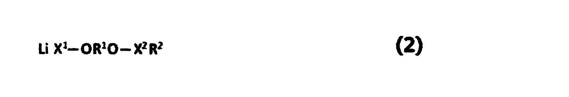

で表される1種以上の化合物を含み、前記正極物質層Cy面の単位質量当たり含有量をCy3(mol/g)とするとき、Cy3が1.60×10-4以上300×10-4以下であることが好ましく、5.0×10-4mol/g以上150×10-4以下であることが更に好ましい。
Cy面にリチウム化合物が含まれることで高負荷充放電サイクルにおける抵抗上昇を抑制することができるが、一方で前記リチウム化合物は高温高電圧環境下に曝されると徐々に分解してガス発生してしまう。そのため、前記式(1)~(3)で表される化合物をCy面に含むことで、高温高電圧環境下でのリチウム化合物の分解を抑制することができる。Cy3が1.60×10⁻⁴以上であれば高温耐久性に優れる。Cy3が300×10-4以下であれば、出力特性に優れる。 <Suppression of decomposition of lithium compounds under high temperature environment Deposits of positive and negative electrodes>
On the positive electrode active material layer Cy surface, the following formulas (1) to (3):
When the content per unit mass of the positive electrode material layer Cy surface is C y3 (mol / g), C y3 is 1.60 × 10 −4 or more and 300 × preferably 10 at -4, and more preferably 5.0 × 10 -4 mol / g or more 0.99 × 10 -4 or less.
Inclusion of a lithium compound on the Cy surface can suppress an increase in resistance in a high-load charge / discharge cycle. On the other hand, the lithium compound gradually decomposes and generates gas when exposed to a high temperature and high voltage environment. Resulting in. Therefore, by including the compounds represented by the above formulas (1) to (3) in the Cy plane, it is possible to suppress the decomposition of the lithium compound under a high temperature and high voltage environment. When Cy3 is 1.60 × 10 −4 or more, the high temperature durability is excellent. If Cy3 is 300 × 10 −4 or less, the output characteristics are excellent.
(静電容量)
本明細書では、静電容量Fa(F)とは、以下の方法によって得られる値である:
先ず、非水系リチウム蓄電素子と対応するセルを25℃に設定した恒温槽内で、20Cの電流値で3.8Vに到達するまで定電流充電を行い、続いて3.8Vの定電圧を印加する定電圧充電を合計で30分行う。その後、2.2Vまで2Cの電流値で定電流放電を施した際の容量をQ(C)とする。ここで得られたQ及び電圧変化ΔVx(V)を用いて、静電容量F=Q/ΔVx=Q/(3.8-2.2)により算出される値をいう。
ここで電流の放電レート(「Cレート」とも呼ばれる)とは、放電容量に対する放電時の電流の相対的な比率であり、一般に、上限電圧から下限電圧まで定電流放電を行う際、1時間で放電が完了する電流値のことを1Cという。本明細書では、上限電圧3.8Vから下限電圧2.2Vまで定電流放電を行う際に1時間で放電が完了する電流値のことを1Cとする。 <Characteristic evaluation of non-aqueous lithium storage element>
(Capacitance)
In the present specification, the capacitance Fa (F) is a value obtained by the following method:
First, constant-current charging is performed in a thermostat set at 25 ° C. with a cell corresponding to the nonaqueous lithium storage element until reaching 3.8 V at a current value of 20 C, and then a constant voltage of 3.8 V is applied. The constant voltage charging is performed for a total of 30 minutes. Then, let Q (C) be the capacity when constant current discharge is performed at a current value of 2C up to 2.2V. The value calculated by the capacitance F = Q / ΔV x = Q / (3.8−2.2) using the Q and the voltage change ΔV x (V) obtained here.
Here, the current discharge rate (also referred to as “C rate”) is the relative ratio of the current during discharge to the discharge capacity. In general, when performing constant current discharge from the upper limit voltage to the lower limit voltage, it takes 1 hour. The current value at which discharge is completed is referred to as 1C. In this specification, when a constant current discharge is performed from an upper limit voltage of 3.8 V to a lower limit voltage of 2.2 V, the current value at which discharge is completed in 1 hour is defined as 1C.
本明細書では、内部抵抗Ra(Ω)とは、それぞれ、以下の方法によって得られる値である:
先ず、非水系リチウム蓄電素子を25℃に設定した恒温槽内で、20Cの電流値で3.8Vに到達するまで定電流充電し、続いて3.8Vの定電圧を印加する定電圧充電を合計で30分間行う。続いて、サンプリング間隔を0.1秒とし、20Cの電流値で2.2Vまで定電流放電を行って、放電カーブ(時間-電圧)を得る。この放電カーブにおいて、放電時間2秒及び4秒の時点における電圧値から、直線近似にて外挿して得られる放電時間=0秒における電圧をVoとしたときに、降下電圧ΔV=3.8-VoからRa=ΔV/(20Cの電流値)として算出される値である。
(電力量)
本明細書では、電力量E(Wh)とは、以下の方法によって得られる値である:
先に述べた方法で算出された静電容量Fa(F)を用いて、電力量E=F×(3.82-2.22)/7200により算出される値をいう。 (Internal resistance)
In the present specification, the internal resistance Ra (Ω) is a value obtained by the following method, respectively:
First, constant-current charging is performed until a non-aqueous lithium battery element reaches 3.8 V at a current value of 20 C in a thermostat set to 25 ° C., and then a constant voltage of 3.8 V is applied. Perform a total of 30 minutes. Subsequently, the sampling interval is set to 0.1 second, and a constant current discharge is performed up to 2.2 V at a current value of 20 C to obtain a discharge curve (time-voltage). In this discharge curve, when the voltage at the discharge time = 0 seconds obtained by extrapolation from the voltage values at the discharge time of 2 seconds and 4 seconds by linear approximation is Vo, the drop voltage ΔV = 3.8− It is a value calculated from Vo as Ra = ΔV / (20C current value).
(Electric energy)
In this specification, the electric energy E (Wh) is a value obtained by the following method:
A value calculated by the electric energy E = F × (3.8 2 −2.2 2 ) / 7200 using the capacitance Fa (F) calculated by the above-described method.
蓄電素子の体積は、特に指定はないが、電極積層体又は電極捲回体のうち、正極活物質層および負極活物質層が積重された領域が、外装体によって収納された部分の体積を指す。
例えば、ラミネートフィルムによって収納された電極積層体又は電極捲回体の場合は、電極積層体又は電極捲回体のうち、正極活物質層および負極活物質層が存在する領域が、カップ成形されたラミネートフィルムの中に収納されるが、この蓄電素子の体積(Vx)は、このカップ成形部分の外寸長さ(lx)と外寸幅(wx)、およびラミネートフィルムを含めた蓄電素子の厚み(tx)により、Vx=lx×wx×txで計算される。
角型の金属缶に収納された電極積層体又は電極捲回体の場合は、蓄電素子の体積としては、単にその金属缶の外寸での体積を用いる。すなわち、この蓄電素子の体積(Vy)は、角型の金属缶の外寸長さ(ly)と外寸幅(wy)、外寸厚み(ty)により、Vy=ly×wy×tyで計算される。
また、円筒型の金属缶に収納された電極捲回体の場合においても、蓄電素子の体積としては、その金属缶の外寸での体積を用いる。すなわち、この蓄電素子の体積(Vz)は、円筒型の金属缶の底面または上面の外寸半径(r)、外寸長さ(lz)により、Vz=3.14×r×r×lzで計算される。 (volume)
The volume of the storage element is not particularly specified, but in the electrode laminate or the electrode winding body, the area where the positive electrode active material layer and the negative electrode active material layer are stacked is the volume of the portion accommodated by the outer package. Point to.
For example, in the case of an electrode laminate or an electrode winding body accommodated by a laminate film, a region where the positive electrode active material layer and the negative electrode active material layer exist in the electrode laminate or the electrode winding body is cup-shaped. Although stored in the laminate film, the volume (V x ) of the electricity storage element is the electricity storage including the outer dimension length (l x ) and outer dimension width (w x ) of the cup-molded portion, and the laminate film. V x = l x × w x × t x is calculated based on the thickness (t x ) of the element.
In the case of an electrode laminate or an electrode winding body housed in a rectangular metal can, the volume of the electric storage element is simply the volume at the outer dimension of the metal can. That is, the volume of the storage element (V y), the outer dimensions length of the square of the metal can (l y) to the outer dimension width (w y), the outer dimensions thickness (t y), V y = l y × is calculated by w y × t y.
Also, in the case of the electrode winding body housed in a cylindrical metal can, the volume of the external dimension of the metal can is used as the volume of the power storage element. That is, the volume (V z ) of this electricity storage element is V z = 3.14 × r × r depending on the outer dimension radius (r) and outer dimension length (l z ) of the bottom or top surface of the cylindrical metal can. × is calculated by l z.
本明細書では、高負荷充放電サイクル試験後の容量維持率は、以下の方法によって測定する:先ず、非水系リチウム蓄電素子と対応するセルを25℃に設定した恒温槽内で、200C又は300Cの電流値で3.8Vに到達するまで定電流充電し、続いて200C又は300Cの電流値で2.2Vに到達するまで定電流放電を行う。前記充放電工程を60000回繰り返し、その後20Cの電流値で電圧4.5Vに到達後、定電圧で1時間充電する。その後、上述の方法にて静電容量測定を行うことでFbを求め、試験開始前の静電容量Faと比較することで、試験開始前に対する高負荷充放電サイクル試験後の容量維持率が求められる。この時、Fb/Faが1.01以上であれば、例えば長期間充放電を行った蓄電素子でも十分な容量のエネルギーを取り出すことができるため、蓄電素子の交換サイクルを延ばすことができるため好ましい。
(高負荷充放電サイクル後の抵抗変化率)
高負荷充放電サイクルを60000回繰り返した後、上記内部抵抗の測定方法に従い高負荷充放電サイクル後の内部抵抗Rbを測定する。Rb/Raを高負荷充放電サイクル後の抵抗変化率とする。本発明の第三の態様においては、高負荷充放電サイクル試験後の抵抗変化率Rb/Raは、好ましくは2.0以下、より好ましくは1.5以下、更に好ましくは1.2以下である。高負荷充放電サイクル試験後の抵抗変化率が2.0以下であれば、充放電を繰り返しても非水系リチウム蓄電素子の特性が維持されるため、長期間安定して優れた入出力特性を得ることができ、非水系リチウム蓄電素子の長寿命化につながる。Rb/Raの下限値は、好ましくは0.9以上である。 (High load charge / discharge cycle test)
In this specification, the capacity maintenance rate after the high-load charge / discharge cycle test is measured by the following method: First, in a thermostatic chamber in which the cell corresponding to the non-aqueous lithium electricity storage element is set to 25 ° C., 200C or 300C. Charge at a constant current until it reaches 3.8V, and then discharge at constant current until it reaches 2.2V at a current value of 200C or 300C. The charging / discharging process is repeated 60000 times, and after reaching a voltage of 4.5 V at a current value of 20 C, charging is performed at a constant voltage for 1 hour. Thereafter, Fb is obtained by measuring the capacitance by the above-mentioned method, and the capacity maintenance ratio after the high load charge / discharge cycle test with respect to before the test is obtained by comparing with Fc before the test is started. It is done. At this time, it is preferable that Fb / Fa is 1.01 or more because, for example, a sufficient amount of energy can be taken out even in a power storage element that has been charged and discharged for a long period of time, so that the replacement cycle of the power storage element can be extended. .
(Rate of change in resistance after high-load charge / discharge cycles)
After the high load charge / discharge cycle is repeated 60000 times, the internal resistance Rb after the high load charge / discharge cycle is measured according to the above-described internal resistance measurement method. Let Rb / Ra be the rate of change in resistance after a high load charge / discharge cycle. In the third aspect of the present invention, the resistance change rate Rb / Ra after the high load charge / discharge cycle test is preferably 2.0 or less, more preferably 1.5 or less, and further preferably 1.2 or less. . If the rate of change in resistance after a high-load charge / discharge cycle test is 2.0 or less, the characteristics of the non-aqueous lithium electricity storage device are maintained even after repeated charge / discharge. Can be obtained, leading to a long life of the non-aqueous lithium storage element. The lower limit value of Rb / Ra is preferably 0.9 or more.
本明細書中、高温保存試験時のガス発生量は、以下の方法によって測定する:
先ず、非水系リチウム蓄電素子と対応するセルを25℃に設定した恒温槽内で、100Cの電流値で4.0Vに到達するまで定電流充電し、次いで、4.0Vの定電圧を印加する定電圧充電を10分間行う。次いで、非水系リチウム蓄電素子を60℃環境下に保存し、2週間毎に60℃環境下から取り出し、前述の充電工程にてセル電圧を4.0Vに充電した後、再び非水系リチウム蓄電素子を60℃環境下で保存する。この工程を繰り返し行い、保存開始前のセル体積Va、保存試験2か月後のセル体積Vbをアルキメデス法によって測定する。アルキメデス法による体積測定に用いる溶媒としては特に限定されないが、電気伝導度が10μS/cm以下であり、非水系リチウム蓄電素子を浸漬させた場合に電気分解が起こらない溶媒を用いることが好ましい。例えば、純水、フッ素系不活性液体が好適に用いられる。特に、高い比重を持ち、優れた電気絶縁性を持つという観点から、フッ素系不活性液体、例えばフロリナート(商標登録、スリーエムジャパン株式会社)FC-40、FC-43等が好適に用いられる。Vb-Vaがセル電圧4.0V及び環境温度60℃において2か月間保存した際に発生するガス量であり、前記静電容量Faで規格化した値B=(Vb-Va)/Faが高温保存試験での規格化発生ガス量である。 (Gas generation after high-temperature storage test)
In the present specification, the amount of gas generated during the high-temperature storage test is measured by the following method:
First, constant-current charging is performed until a voltage of 100 C reaches 4.0 V in a thermostat set to 25 ° C. with a cell corresponding to the non-aqueous lithium storage element, and then a constant voltage of 4.0 V is applied. Perform constant voltage charging for 10 minutes. Next, the non-aqueous lithium storage element is stored in a 60 ° C. environment, taken out from the 60 ° C. environment every two weeks, charged with a cell voltage of 4.0 V in the above-described charging step, and then again non-aqueous lithium storage element. Is stored at 60 ° C. This process is repeated, and the cell volume Va before the start of storage and the cell volume Vb after 2 months of the storage test are measured by Archimedes method. Although it does not specifically limit as a solvent used for the volume measurement by Archimedes method, It is preferable to use the solvent whose electrical conductivity is 10 microsiemens / cm or less, and when electrolysis does not occur when a non-aqueous lithium electrical storage element is immersed. For example, pure water or a fluorine-based inert liquid is preferably used. In particular, from the viewpoint of having a high specific gravity and excellent electrical insulation, fluorine-based inert liquids such as Fluorinert (trademark registered, 3M Japan Co., Ltd.) FC-40, FC-43, etc. are preferably used. Vb−Va is the amount of gas generated when stored for 2 months at a cell voltage of 4.0V and an environmental temperature of 60 ° C., and the value B = (Vb−Va) / Fa normalized by the capacitance Fa is high. This is the normalized amount of gas generated in the storage test.
(a)Rc/Raが3.0以下である、並びに
(b)セル電圧4V及び環境温度60℃において2か月間保存したときに発生するガス量Vb-Va(cc)を、静電容量Faで規格化した値Bが5×10⁻³cc/F以下であるの両方を同時に満たすことが好ましい。 The non-aqueous lithium storage element of this embodiment has an internal resistance Rc (Ω) at a cell voltage of 3.8 V measured as described above, an internal resistance before storage Ra (Ω), and a capacitance before storage Fa. When (F), the following conditions (a) and (b):
(A) Rc / Ra is 3.0 or less, and (b) The amount of gas Vb−Va (cc) generated when stored for 2 months at a cell voltage of 4 V and an environmental temperature of 60 ° C. is expressed as capacitance Fa It is preferable that both of the values B normalized by the above are simultaneously 5 × 10 −3 cc / F or less.
正極中に含まれるリチウム化合物の同定方法は特に限定されないが、例えば下記の方法により同定することができる。リチウム化合物の同定には、以下に記載する複数の解析手法を組み合わせて同定することが好ましい。
以下に記載するSEM-EDX、ラマン、XPSを測定する際には、アルゴンボックス中で非水系リチウム蓄電素子を解体して正極を取り出し、正極表面に付着した電解質を洗浄した後に測定を行うことが好ましい。正極の洗浄方法については、正極表面に付着した電解質を洗い流せればよいため、ジメチルカーボネート、エチルメチルカーボネート、ジエチルカーボネート等のカーボネート溶媒が好適に利用できる。洗浄方法としては例えば、正極重量の50~100倍のジエチルカーボネート溶媒に正極を10分間以上浸漬させ、その後溶媒を取り替えて再度正極を浸漬させる。その後正極をジエチルカーボネートから取り出し、真空乾燥(温度:0~200℃、圧力:0~20kPa、時間:1~40時間の範囲で正極中のジエチルカーボネートの残存が1質量%以下になる条件とする。ジエチルカーボネートの残存量については、後述する蒸留水洗浄、液量調整後の水のGC/MSを測定し、予め作成した検量線を基に定量することができる。)させた後に、前記SEM-EDX、ラマン、XPSの解析を実施する。
後述するイオンクロマトグラフィーについては、正極を蒸留水で洗浄した後の水を解析することにより陰イオンを同定することができる。
前記解析手法にてリチウム化合物を同定できなかった場合、その他の解析手法として、7Li-固体NMR、XRD(X線回折)、TOF-SIMS(飛行時間型二次イオン質量分析)、AES(オージェ電子分光)、TPD/MS(加熱発生ガス質量分析)、DSC(示差走査熱量分析)等を用いることにより、リチウム化合物を同定することもできる。 <Identification method of lithium compound in electrode>
Although the identification method of the lithium compound contained in a positive electrode is not specifically limited, For example, it can identify by the following method. It is preferable to identify a lithium compound by combining a plurality of analysis methods described below.
When measuring SEM-EDX, Raman, and XPS described below, measurement may be performed after disassembling the non-aqueous lithium storage element in an argon box, taking out the positive electrode, and washing the electrolyte adhering to the positive electrode surface. preferable. Regarding the method for cleaning the positive electrode, it is only necessary to wash away the electrolyte adhering to the surface of the positive electrode. Therefore, carbonate solvents such as dimethyl carbonate, ethyl methyl carbonate, and diethyl carbonate can be suitably used. As a cleaning method, for example, the positive electrode is immersed in a diethyl carbonate solvent 50 to 100 times the weight of the positive electrode for 10 minutes or more, and then the solvent is changed and the positive electrode is immersed again. Thereafter, the positive electrode is taken out from diethyl carbonate and dried in a vacuum (temperature: 0 to 200 ° C., pressure: 0 to 20 kPa, time: 1 to 40 hours, so that the residual amount of diethyl carbonate in the positive electrode is 1% by mass or less. The residual amount of diethyl carbonate can be determined based on a calibration curve prepared in advance by measuring the GC / MS of water after washing with distilled water and adjusting the liquid volume, which will be described later. -Perform EDX, Raman and XPS analysis.
As for ion chromatography described later, anions can be identified by analyzing the water after washing the positive electrode with distilled water.
When a lithium compound cannot be identified by the above analysis method, other analysis methods include 7 Li-solid NMR, XRD (X-ray diffraction), TOF-SIMS (time-of-flight secondary ion mass spectrometry), AES (Auger) Lithium compounds can also be identified by using electron spectroscopy, TPD / MS (heat generation gas mass spectrometry), DSC (differential scanning calorimetry), or the like.
酸素を含有するリチウム化合物及び正極活物質は、観察倍率を1000倍~4000倍にして測定した正極表面のSEM-EDX画像による酸素マッピングにより判別できる。SEM-EDX画像の測定例として、加速電圧を10kV、エミッション電流を10μA、測定画素数を256×256ピクセル、積算回数を50回として測定できる。試料の帯電を防止するために、金、白金、オスミウム等を真空蒸着やスパッタリング等の方法により表面処理することもできる。SEM-EDX画像の測定方法については、マッピング像において最大輝度値に達する画素がなく、輝度値の平均値が最大輝度値の40%~60%の範囲に入るように輝度及びコントラストを調整することが好ましい。得られた酸素マッピングに対し、輝度値の平均値を基準に二値化した明部を面積50%以上含む粒子をリチウム化合物とする。 [Scanning electron microscope-energy dispersive X-ray analysis (SEM-EDX)]
The lithium compound containing oxygen and the positive electrode active material can be discriminated by oxygen mapping using a SEM-EDX image of the positive electrode surface measured at an observation magnification of 1000 to 4000 times. As a measurement example of the SEM-EDX image, the acceleration voltage is 10 kV, the emission current is 10 μA, the number of measurement pixels is 256 × 256 pixels, and the number of integrations is 50. In order to prevent charging of the sample, gold, platinum, osmium, or the like can be surface-treated by a method such as vacuum deposition or sputtering. Regarding the SEM-EDX image measurement method, the brightness and contrast are adjusted so that there is no pixel that reaches the maximum luminance value in the mapping image, and the average value of the luminance values is in the range of 40% to 60% of the maximum luminance value. Is preferred. With respect to the obtained oxygen mapping, particles containing 50% or more area of bright portions binarized based on the average value of luminance are defined as lithium compounds.
炭酸イオンからなるリチウム化合物及び正極活物質は、観察倍率を1000倍~4000倍にして測定した正極表面のラマンイメージングにより判別できる。測定条件の例として、励起光を532nm、励起光強度を1%、対物レンズの長作動を50倍、回折格子を1800gr/mm、マッピング方式を点走査(スリット65mm、ビニング5pix)、1mmステップ、1点当たりの露光時間を3秒、積算回数を1回、ノイズフィルター有りの条件にて測定することができる。測定したラマンスペクトルについて、1071~1104cm-1の範囲で直線のベースラインを設定し、ベースラインより正の値を炭酸イオンのピークとして面積を算出し、頻度を積算するが、この時にノイズ成分をガウス型関数で近似した炭酸イオンピーク面積に対する頻度を前記炭酸イオンの頻度分布から差し引く。 [Micro Raman spectroscopy]
The lithium compound comprising a carbonate ion and the positive electrode active material can be discriminated by Raman imaging of the positive electrode surface measured at an observation magnification of 1000 to 4000 times. As an example of measurement conditions, the excitation light is 532 nm, the excitation light intensity is 1%, the long operation of the objective lens is 50 times, the diffraction grating is 1800 gr / mm, the mapping method is point scanning (slit 65 mm, binning 5 pix), 1 mm step, The exposure time per point can be measured for 3 seconds, the number of integrations is 1, and measurement can be performed with a noise filter. For the measured Raman spectrum, a linear baseline is set in the range of 1071 to 1104 cm −1 , and the area is calculated with a positive value from the baseline as the peak of carbonate ions, and the frequency is integrated. The frequency for the carbonate ion peak area approximated by a Gaussian function is subtracted from the carbonate ion frequency distribution.
リチウムの電子状態をXPSにより解析することによりリチウムの結合状態を判別することができる。測定条件の例として、X線源を単色化AlKα、X線ビーム径を100μmφ(25W、15kV)、パスエネルギーをナロースキャン:58.70eV、帯電中和有り、スイープ数をナロースキャン:10回(炭素、酸素)20回(フッ素)30回(リン)40回(リチウム)50回(ケイ素)、エネルギーステップをナロースキャン:0.25eVの条件にて測定できる。XPSの測定前に正極の表面をスパッタリングにてクリーニングすることが好ましい。スパッタリングの条件として例えば、加速電圧1.0kV、2mm×2mmの範囲を1分間(SiO2換算で1.25nm/min)の条件にて正極の表面をクリーニングすることができる。得られたXPSスペクトルについて、Li1sの結合エネルギー50~54eVのピークをLiO2またはLi-C結合、55~60eVのピークをLiF、Li2CO3、LixPOyFz(x、y、zは1~6の整数)、C1sの結合エネルギー285eVのピークをC-C結合、286eVのピークをC-O結合、288eVのピークをCOO、290~292eVのピークをCO3 2-、C-F結合、O1sの結合エネルギー527~530eVのピークをO2-(Li2O)、531~532eVのピークをCO、CO3、OH、POx(xは1~4の整数)、SiOx(xは1~4の整数)、533eVのピークをC-O、SiOx(xは1~4の整数)、F1sの結合エネルギー685eVのピークをLiF、687eVのピークをC-F結合、LixPOyFz(x、y、zは1~6の整数)、PF6 -、P2pの結合エネルギーについて、133eVのピークをPOx(xは1~4の整数)、134~136eVのピークをPFx(xは1~6の整数)、Si2pの結合エネルギー99eVのピークをSi、シリサイド、101~107eVのピークをSixOy(x、yは任意の整数)として帰属することができる。得られたスペクトルについて、ピークが重なる場合には、ガウス関数又はローレンツ関数を仮定してピーク分離し、スペクトルを帰属することが好ましい。前記で得られた電子状態の測定結果及び存在元素比の結果から、存在するリチウム化合物を同定することができる。 [X-ray photoelectric spectroscopy (XPS)]
By analyzing the electronic state of lithium by XPS, the bonding state of lithium can be determined. As an example of measurement conditions, the X-ray source is monochromatic AlKα, the X-ray beam diameter is 100 μmφ (25 W, 15 kV), the path energy is narrow scan: 58.70 eV, charging neutralization is performed, and the number of sweeps is narrow scan: 10 times ( Carbon, oxygen) 20 times (fluorine) 30 times (phosphorus) 40 times (lithium) 50 times (silicon), energy step can be measured under the condition of narrow scan: 0.25 eV. It is preferable to clean the surface of the positive electrode by sputtering before the XPS measurement. As the sputtering condition, for example, the surface of the positive electrode can be cleaned under the condition of an acceleration voltage of 1.0 kV and a range of 2 mm × 2 mm for 1 minute (1.25 nm / min in terms of SiO 2 ). Regarding the obtained XPS spectrum, the peak of Li1s binding energy of 50 to 54 eV is LiO 2 or Li—C bond, and the peak of 55 to 60 eV is LiF, Li 2 CO 3 , Li x PO y F z (x, y, z Is an integer of 1 to 6), C1s has a bond energy of 285 eV, a C—C bond, 286 eV has a peak of CO bond, 288 eV has a peak of COO, 290 to 292 eV has a peak of CO 3 2− , C—F The peak of the bond, O1s binding energy of 527 to 530 eV is O 2− (Li 2 O), and the peak of 531 to 532 eV is CO, CO 3 , OH, PO x (x is an integer of 1 to 4), SiO x (x is an integer of 1-4), a peak of 533 eV C-O, integer SiO x (x is 1-4), the peak of binding energy 685eV of F1s Li , C-F bonds and a peak of 687eV, Li x PO y F z (x, y, z is an integer of 1 ~ 6), PF 6 - , for the binding energy of the P2p, the peak of 133eV PO x (x 1 ), The peak of 134 to 136 eV is represented by PF x (x is an integer of 1 to 6), the peak of Si2p binding energy of 99 eV is Si, silicide, and the peak of 101 to 107 eV is represented by Si x O y (x, y Can be attributed as any integer). When peaks are overlapped in the obtained spectrum, it is preferable to perform peak separation assuming a Gaussian function or a Lorentz function and assign the spectrum. An existing lithium compound can be identified from the measurement result of the electronic state and the result of the ratio of existing elements obtained above.
正極の蒸留水洗浄液をイオンクロマトグラフィーで解析することにより、水中に溶出したアニオン種を同定することができる。使用するカラムとしては、イオン交換型、イオン排除型、逆相イオン対型を使用することができる。検出器としては、電気伝導度検出器、紫外可視吸光光度検出器、電気化学検出器等を使用することができ、検出器の前にサプレッサーを設置するサプレッサー方式、またはサプレッサーを配置せずに電気伝導度の低い溶液を溶離液に用いるノンサプレッサー方式を用いることができる。また、質量分析計や荷電化粒子検出を検出器と組み合わせて測定することもできるため、SEM-EDX、ラマン、XPSの解析結果から同定されたリチウム化合物を基に適切なカラム、検出器を組み合わせることが好ましい。
サンプルの保持時間は、使用するカラムや溶離液等の条件が決まれば、イオン種成分毎に一定であり、またピークのレスポンスの大きさはイオン種毎に異なるが濃度に比例する。トレーサビリティーが確保された既知濃度の標準液を予め測定しておくことでイオン種成分の定性と定量が可能となる。 [Ion chromatography]
Anion species eluted in water can be identified by analyzing the positive electrode distilled water washing solution by ion chromatography. As a column to be used, an ion exchange type, an ion exclusion type, or a reverse phase ion pair type can be used. As the detector, an electrical conductivity detector, an ultraviolet-visible absorption detector, an electrochemical detector, or the like can be used. A suppressor system in which a suppressor is installed in front of the detector, A non-suppressor method using a solution with low conductivity as the eluent can be used. In addition, mass spectrometers and charged particle detection can be combined with detectors, so appropriate columns and detectors are combined based on lithium compounds identified from SEM-EDX, Raman, and XPS analysis results. It is preferable.
The sample retention time is constant for each ion species component if conditions such as the column to be used and the eluent are determined, and the magnitude of the peak response varies with each ion species but is proportional to the concentration. It is possible to qualitatively and quantitatively determine the ionic species component by measuring in advance a standard solution having a known concentration in which traceability is ensured.
測定試料について、濃硝酸、濃塩酸、王水等の強酸を用いて酸分解し、得られた溶液を2%~3%の酸濃度になるように純水で希釈する。酸分解については、適宜加熱、加圧し分解することもできる。得られた希釈液をICP-MSにより解析するがこの際に内部標準として既知量の元素を加えておくことが好ましい。測定対象のアルカリ金属元素が測定上限濃度以上になる場合には、希釈液の酸濃度を維持したまま更に希釈することが好ましい。得られた測定結果に対し、化学分析用の標準液を用いて予め作成した検量線を基に、各元素を定量することができる。 <Quantitative determination method of alkali metal elements ICP-MS>
The measurement sample is acid-decomposed using a strong acid such as concentrated nitric acid, concentrated hydrochloric acid, aqua regia, etc., and the resulting solution is diluted with pure water so that the acid concentration is 2% to 3%. About acid decomposition, it can also decompose by heating and pressurizing suitably. The obtained diluted solution is analyzed by ICP-MS. At this time, it is preferable to add a known amount of element as an internal standard. When the alkali metal element to be measured is equal to or higher than the measurement upper limit concentration, it is preferable to further dilute while maintaining the acid concentration of the diluted solution. With respect to the obtained measurement results, each element can be quantified based on a calibration curve prepared in advance using a standard solution for chemical analysis.
正極中に含まれるリチウム化合物の定量方法を以下に記載する。正極を有機溶媒で洗浄し、その後蒸留水で洗浄し、蒸留水での洗浄前後の正極重量変化からリチウム化合物を定量することができる。測定する正極の面積は特に制限されないが、測定のばらつきを軽減するという観点から5cm2以上200cm2以下であることが好ましく、更に好ましくは25cm2以上150cm2以下である。面積が5cm2以上あれば測定の再現性が確保される。面積が200cm2以下であればサンプルの取扱い性に優れる。有機溶媒による洗浄については正極表面に堆積した電解液分解物を除去できれば良いため、有機溶媒は特に限定されないが、前記リチウム化合物の溶解度が2%以下である有機溶媒を用いることでリチウム化合物の溶出が抑制されるため好ましい。例えばメタノール、エタノール、アセトン、酢酸メチル等の極性溶媒が好適に用いられる。 <Quantitative method of lithium compound>
A method for quantifying the lithium compound contained in the positive electrode is described below. The positive electrode is washed with an organic solvent, then washed with distilled water, and the lithium compound can be quantified from the change in the weight of the positive electrode before and after washing with distilled water. Although area measurement is positive is not particularly limited, it is preferably, more preferably 25 cm 2 or more 150 cm 2 or less from the viewpoint of reducing the variation in measurement is 5 cm 2 or more 200 cm 2 or less. If the area is 5 cm 2 or more, the reproducibility of measurement is ensured. If the area is 200 cm 2 or less, the sample is easy to handle. The organic solvent is not particularly limited as long as it can remove the electrolyte solution deposited on the surface of the positive electrode for washing with an organic solvent, but the elution of the lithium compound can be achieved by using an organic solvent having a lithium compound solubility of 2% or less. Is preferable. For example, polar solvents such as methanol, ethanol, acetone, and methyl acetate are preferably used.
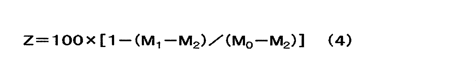
上述の様に上記極性溶媒で洗浄し、真空乾燥後に得られた正極を半分に切断し、一方を正極Cx0とし、残りを正極Cy0とし、面積をそれぞれXC(m2)及びYC(m2)とする。スパチュラ、ブラシ、刷毛等を用いて正極Cx0のCy面の正極活物質層、及び正極Cy0のCx面の正極活物質層を取り除き、正極Cx0の重量をM0x(g)、及び正極Cy0の重量をM0y(g)とする。続いて、正極Cx0及び正極Cy0をそれぞれの重量の100~150倍の蒸留水に3日間以上十分に浸漬させる。浸漬の間、蒸留水が揮発しないよう容器に蓋をすることが好ましく、リチウム化合物の溶出を促進させるために時折水溶液を撹拌させることが好ましい。3日間以上浸漬させた後、蒸留水から正極Cx0及び正極Cy0を取り出し、上記のエタノール洗浄と同様に真空乾燥する。真空乾燥後の正極Cx0及び正極Cy0の重量をそれぞれM1x(g)及びM1y(g)とする。続いて、得られた正極Cx0及び正極Cy0の集電体の重量を測定するため、スパチュラ、ブラシ、刷毛等を用いて正極Cx0及び正極Cy0に残った正極活物質層を取り除く。得られた正極集電体の重量をM2x(g)及びM2y(g)とすると、正極Cx0の正極活物質層の目付Cx1(g/m2)、及び正極Cy0の正極活物質層の目付Cy1(g/m2)は(5)式にて算出できる。
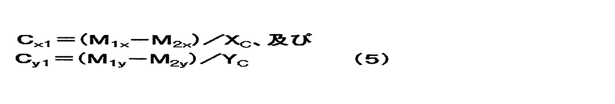
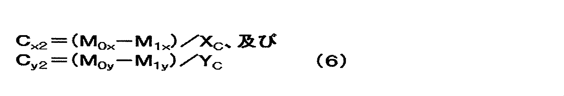
As described above, the positive electrode obtained after washing with the polar solvent and vacuum-dried is cut in half, one is designated as positive electrode C x0 , the other as positive electrode C y0 , and the areas are X C (m 2 ) and Y C, respectively. (M 2 ). Using a spatula, brush, brush, etc., the positive electrode active material layer on the C y surface of the positive electrode C x0 and the positive electrode active material layer on the C x surface of the positive electrode C y0 are removed, and the weight of the positive electrode C x0 is M 0x (g), The weight of the positive electrode C y0 is M 0y (g). Subsequently, the positive electrode C x0 and the positive electrode C y0 are sufficiently immersed in distilled water 100 to 150 times their weight for 3 days or more. It is preferable to cover the container so that distilled water does not volatilize during the immersion, and it is preferable to occasionally stir the aqueous solution to promote elution of the lithium compound. After being immersed for 3 days or more, the positive electrode C x0 and the positive electrode C y0 are taken out from distilled water and vacuum-dried in the same manner as the above ethanol cleaning. The weights of the positive electrode C x0 and the positive electrode C y0 after the vacuum drying are defined as M 1x (g) and M 1y (g), respectively. Subsequently, for measuring the weight of the current collector of the positive electrode obtained C x0 and positive C y0, spatula, brush, it removes the remaining active material layer on the positive electrode C x0 and positive C y0 using a brush or the like. If the weight of the obtained positive electrode collector and the M 2x (g) and M 2y (g), the positive electrode active having a mass per unit area C x1 (g / m 2) , and a positive electrode C y0 of the positive electrode active material layer of the positive electrode C x0 The basis weight C y1 (g / m 2 ) of the material layer can be calculated by the equation (5).
負極活物質層の目付の定量方法を以下に記載する。前記アルゴンボックス中で電極積層体から負極を切り出して有機溶媒で洗浄する。洗浄に使用する有機溶媒としては、負極表面に堆積した電解液分解物を除去し、負極中のリチウムイオンと反応する溶媒がよく、特に限定されないが、メタノール、エタノール、イソプロパノール等のアルコール、又はこれらの混合溶媒が好適に用いられる。測定する負極の面積は特に制限されないが、測定のばらつきを軽減するという観点から5cm2以上200cm2以下であることが好ましく、更に好ましくは25cm2以上150cm2以下である。面積が5cm2以上あれば測定の再現性が確保される。面積が200cm2以下であればサンプルの取扱い性に優れる。 <Calculation of the weight per unit area of the negative electrode active material layer> Calculation of A x1 and A y1 >
A method for determining the basis weight of the negative electrode active material layer is described below. A negative electrode is cut out from the electrode laminate in the argon box and washed with an organic solvent. The organic solvent used for cleaning is preferably a solvent that removes the electrolyte decomposition product deposited on the negative electrode surface and reacts with lithium ions in the negative electrode, and is not particularly limited, but alcohols such as methanol, ethanol, isopropanol, or the like The mixed solvent is preferably used. Although the area of the negative electrode to be measured is not particularly limited, it is preferably, more preferably 25 cm 2 or more 150 cm 2 or less from the viewpoint of reducing the variation in measurement is 5 cm 2 or more 200 cm 2 or less. If the area is 5 cm 2 or more, the reproducibility of measurement is ensured. If the area is 200 cm 2 or less, the sample is easy to handle.
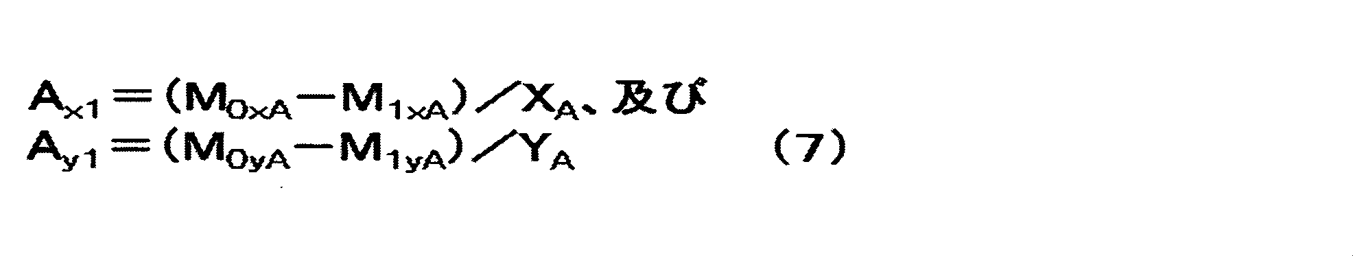
以下、第一の態様における実施形態について具体的に説明する。
<実施例1>
<正極活物質の調製>
[調製例1a]
破砕されたヤシ殻炭化物を、小型炭化炉において窒素中、500℃において3時間炭化処理して炭化物を得た。得られた炭化物を賦活炉内へ入れ、1kg/hの水蒸気を予熱炉で加温した状態で前記賦活炉内へ導入し、900℃まで8時間かけて昇温して賦活した。賦活後の炭化物を取り出し、窒素雰囲気下で冷却して、賦活された活性炭を得た。得られた活性炭を12時間通水洗浄した後に水切りした。その後、125℃に保持された電気乾燥機内で10時間乾燥した後に、ボールミルで1時間粉砕を行うことにより、活性炭1aを得た。
この活性炭1aについて、島津製作所社製レーザー回折式粒度分布測定装置(SALD-2000J)を用いて平均粒子径を測定した結果、12.7μmであった。また、ユアサアイオニクス社製細孔分布測定装置(AUTOSORB-1 AS-1-MP)を用いて細孔分布を測定した。その結果、BET比表面積が2330m2/g、メソ孔量(V1)が0.52cc/g、マイクロ孔量(V2)が0.88cc/g、V1/V2=0.59であった。 Examples and comparative examples will be described below to further clarify the features of the present invention. However, the present invention is not limited to the following examples.
The embodiment in the first aspect will be specifically described below.
<Example 1>
<Preparation of positive electrode active material>
[Preparation Example 1a]
The crushed coconut shell carbide was carbonized in a small carbonization furnace in nitrogen at 500 ° C. for 3 hours to obtain a carbide. The obtained carbide was put into an activation furnace, 1 kg / h of steam was heated in the preheating furnace and introduced into the activation furnace, and the temperature was raised to 900 ° C. over 8 hours for activation. The activated carbide was taken out and cooled in a nitrogen atmosphere to obtain activated activated carbon. The obtained activated carbon was washed with water for 12 hours and then drained. Then, after drying for 10 hours in an electric dryer maintained at 125 ° C., pulverization was performed for 1 hour with a ball mill to obtain activated carbon 1a.
With respect to this activated carbon 1a, the average particle diameter was measured by using a laser diffraction particle size distribution analyzer (SALD-2000J) manufactured by Shimadzu Corporation. As a result, it was 12.7 μm. In addition, pore distribution was measured using a pore distribution measuring device (AUTOSORB-1 AS-1-MP) manufactured by Yuasa Ionics. As a result, the BET specific surface area was 2330 m 2 / g, the mesopore volume (V 1 ) was 0.52 cc / g, the micropore volume (V 2 ) was 0.88 cc / g, and V 1 / V 2 = 0.59. there were.
フェノール樹脂について、窒素雰囲気下、焼成炉中600℃において2時間の炭化処理を行った後、ボールミルにて粉砕し、分級を行って平均粒子径7μmの炭化物を得た。この炭化物とKOHとを、質量比1:5で混合し、窒素雰囲下、焼成炉中800℃において1時間加熱して賦活化を行った。その後濃度2mol/Lに調整した希塩酸中で1時間撹拌洗浄を行った後、蒸留水でpH5~6の間で安定するまで煮沸洗浄した後に乾燥を行うことにより、活性炭2aを得た。
この活性炭2aについて、島津製作所社製レーザー回折式粒度分布測定装置(SALD-2000J)を用いて平均粒子径を測定した結果、7.0μmであった。また、ユアサアイオニクス社製細孔分布測定装置(AUTOSORB-1 AS-1-MP)を用いて細孔分布を測定した。その結果、BET比表面積が3627m2/g、メソ孔量(V1)が1.50cc/g、マイクロ孔量(V2)が2.28cc/g、V1/V2=0.66であった。 [Preparation Example 2a]
The phenolic resin was carbonized for 2 hours at 600 ° C. in a firing furnace under a nitrogen atmosphere, then pulverized with a ball mill and classified to obtain a carbide having an average particle diameter of 7 μm. This carbide and KOH were mixed at a mass ratio of 1: 5, and activated by heating in a firing furnace at 800 ° C. for 1 hour in a nitrogen atmosphere. Thereafter, the mixture was washed with stirring in dilute hydrochloric acid adjusted to a concentration of 2 mol / L for 1 hour, then boiled and washed with distilled water until stable at a pH of 5 to 6, and then dried to obtain activated carbon 2a.
With respect to this activated carbon 2a, the average particle diameter was measured using a laser diffraction particle size distribution analyzer (SALD-2000J) manufactured by Shimadzu Corporation. As a result, it was 7.0 μm. In addition, pore distribution was measured using a pore distribution measuring device (AUTOSORB-1 AS-1-MP) manufactured by Yuasa Ionics. As a result, the BET specific surface area was 3627 m 2 / g, the mesopore volume (V 1 ) was 1.50 cc / g, the micropore volume (V 2 ) was 2.28 cc / g, and V 1 / V 2 = 0.66. there were.
平均粒子径53μmの炭酸リチウム200gを、アイメックス社製の粉砕機(液体窒素ビーズミルLNM)を用い、液体窒素で-196℃に冷却化した後、ドライアイスビーズを用い、周速10.0m/sにて20分間粉砕した。-196℃で熱変性を防止し、脆性破壊することにより得られた炭酸リチウム1について平均粒子径を測定したところ1.8μmであった。 <Lithium carbonate grinding>
200 g of lithium carbonate having an average particle size of 53 μm was cooled to −196 ° C. with liquid nitrogen using a crusher (liquid nitrogen bead mill LNM) manufactured by Imex Co., Ltd., and then peripheral speed was 10.0 m / s using dry ice beads. For 20 minutes. When lithium carbonate 1 obtained by preventing thermal denaturation at −196 ° C. and brittle fracture was measured, the average particle diameter was 1.8 μm.
前記活性炭2aを正極活物質として用い、前記炭酸リチウム1をリチウム化合物として正極前駆体を製造した。
活性炭2aを55.5質量部、炭酸リチウム1を32.0質量部、ケッチェンブラックを3.0質量部、PVP(ポリビニルピロリドン)を1.5質量部、及びPVDF(ポリフッ化ビニリデン)を8.0質量部、並びにNMP(N-メチルピロリドン)を混合し、それをPRIMIX社製の薄膜旋回型高速ミキサーフィルミックスを用いて、周速17m/sの条件で分散して塗工液を得た。得られた塗工液の粘度(ηb)及びTI値を東機産業社のE型粘度計TVE-35Hを用いて測定した。その結果、粘度(ηb)は2,300mPa・s、TI値は3.2であった。また、得られた塗工液の分散度をヨシミツ精機社製の粒ゲージを用いて測定した。その結果、粒度は32μmであった。前記塗工液を東レエンジニアリング社製のダイコーターを用いて厚さ15μmのアルミニウム箔の片面又は両面に塗工速度1m/sの条件で塗工し、乾燥温度120℃で乾燥して正極前駆体1(片面)及び正極前駆体1(両面)を得た。得られた正極前駆体1(片面)及び正極前駆体1(両面)についてロールプレス機を用いて圧力6kN/cm、プレス部の表面温度25℃の条件でプレスを実施した。前記で得られた正極前駆体1(片面)及び正極前駆体1(両面)の正極活物質層の膜厚を小野計器社製膜厚計Linear Gauge Sensor GS-551を用いて、正極前駆体1の任意の10か所で測定した厚さの平均値から、アルミニウム箔の厚さを引いて求めた。その結果、正極活物質層の膜厚は片面あたりの厚さは62μmであった。 <Production of positive electrode precursor>
A positive electrode precursor was manufactured using the activated carbon 2a as a positive electrode active material and the lithium carbonate 1 as a lithium compound.
55.5 parts by mass of activated carbon 2a, 32.0 parts by mass of lithium carbonate 1, 3.0 parts by mass of ketjen black, 1.5 parts by mass of PVP (polyvinylpyrrolidone), and 8 parts of PVDF (polyvinylidene fluoride) 0.0 parts by mass and NMP (N-methylpyrrolidone) are mixed and dispersed using a thin film swirl type high-speed mixer film mix manufactured by PRIMIX under the condition of a peripheral speed of 17 m / s to obtain a coating liquid. It was. The viscosity (ηb) and TI value of the obtained coating solution were measured using an E-type viscometer TVE-35H manufactured by Toki Sangyo Co., Ltd. As a result, the viscosity (ηb) was 2,300 mPa · s, and the TI value was 3.2. Moreover, the dispersion degree of the obtained coating liquid was measured using the grain gauge made from Yoshimitsu Seiki. As a result, the particle size was 32 μm. The coating solution is applied to one or both sides of a 15 μm thick aluminum foil using a die coater manufactured by Toray Engineering Co., Ltd. under a coating speed of 1 m / s and dried at a drying temperature of 120 ° C. 1 (single side) and positive electrode precursor 1 (both sides) were obtained. The obtained positive electrode precursor 1 (single side) and positive electrode precursor 1 (both sides) were pressed using a roll press machine under conditions of a pressure of 6 kN / cm and a surface temperature of the press part of 25 ° C. The thickness of the positive electrode precursor 1 (single side) and the positive electrode active material layer of the positive electrode precursor 1 (both sides) obtained above was measured using a thickness gauge Linear Gauge Sensor GS-551 manufactured by Ono Keiki Co., Ltd. The thickness of the aluminum foil was subtracted from the average value of the thicknesses measured at any 10 points. As a result, the film thickness of the positive electrode active material layer was 62 μm per side.
市販のヤシ殻活性炭のBET比表面積及び細孔分布を、ユアサアイオニクス社製細孔分布測定装置(AUTOSORB-1 AS-1-MP)を用いて、上述した方法によって測定した。その結果、BET比表面積は1,790m2/g、メソ孔量(V1)は0.199cc/g、マイクロ孔量(V2)は0.698cc/g、V1/V2=0.29、そして平均細孔径は20.1Åであった。
このヤシ殻活性炭300gをステンレススチールメッシュ製の籠に入れ、石炭系ピッチ(軟化点:50℃)540gを入れたステンレス製バットの上に置き、両者を電気炉(炉内有効寸法300mm×300mm×300mm)内に設置して、熱反応を行うことにより、複合多孔質炭素材料1a1を得た。この熱処理は窒素雰囲気下で行い、600℃まで8時間で昇温し、同温度で4時間保持する方法によった。続いて自然冷却により60℃まで冷却した後、複合炭素材料1a1を炉から取り出した。
得られた複合炭素材料1a1について、前記と同様の方法でBET比表面積及び細孔分布を測定した。その結果、BET比表面積は262m2/g、メソ孔量(Vm1)は0.186cc/g、マイクロ孔量(Vm2)は0.082cc/g、Vm1/Vm2=2.27であった。また、複合炭素材料1a1において、石炭系ピッチ由来の炭素質材料の活性炭に対する質量比率は78%であった。 <Preparation of Negative Electrode Active Material Preparation Example 1a 1 >
The BET specific surface area and pore distribution of commercially available coconut shell activated carbon were measured by the above-described method using a pore distribution measuring device (AUTOSORB-1 AS-1-MP) manufactured by Yuasa Ionics. As a result, the BET specific surface area was 1,790 m 2 / g, the mesopore volume (V 1 ) was 0.199 cc / g, the micropore volume (V 2 ) was 0.698 cc / g, and V 1 / V 2 = 0. 29, and the average pore diameter was 20.1 mm.
300 g of this coconut shell activated carbon is placed in a stainless steel mesh basket and placed on a stainless steel bat containing 540 g of a coal-based pitch (softening point: 50 ° C.). and placed in 300 mm), by thermal reaction, to obtain a composite porous carbon material 1a 1. This heat treatment was performed in a nitrogen atmosphere, and the temperature was raised to 600 ° C. in 8 hours and kept at the same temperature for 4 hours. Subsequently, after cooling to 60 ° C. by natural cooling, the composite carbon material 1a 1 was taken out from the furnace.
The resulting composite carbon material 1a 1, and the BET specific surface area and pore distribution in the same manner as above. As a result, the BET specific surface area was 262 m 2 / g, the mesopore volume (V m1 ) was 0.186 cc / g, the micropore volume (V m2 ) was 0.082 cc / g, and V m1 / V m2 = 2.27. there were. Moreover, in the composite carbon material 1a 1 , the mass ratio of the carbonaceous material derived from the coal-based pitch to the activated carbon was 78%.
前記複合炭素材料1a1を負極活物質として用いて負極を製造した。
複合炭素材料1a1を84質量部、アセチレンブラックを10質量部、及びPVdF(ポリフッ化ビニリデン)を6質量部、並びにNMP(N-メチルピロリドン)を混合し、それをPRIMIX社製の薄膜旋回型高速ミキサーフィルミックスを用いて、周速17m/sの条件で分散して塗工液を得た。得られた塗工液の粘度(ηb)及びTI値を東機産業社のE型粘度計TVE-35Hを用いて測定した。その結果、粘度(ηb)は2,789mPa・s、TI値は4.3であった。前記塗工液を東レエンジニアリング社製のダイコーターを用いて厚さ10μmの電解銅箔の両面に塗工速度2m/sの条件で塗工し、乾燥温度120℃で乾燥して負極1を得た。得られた負極1についてロールプレス機を用いて圧力5kN/cm、プレス部の表面温度25℃の条件でプレスを実施した。前記で得られた負極1の負極活物質層の膜厚を小野計器社製膜厚計Linear Gauge Sensor GS-551を用いて、負極1の任意の10か所で測定した厚さの平均値から、銅箔の厚さを引いて求めた。その結果、負極活物質層の膜厚は片面あたりの厚さは40μmであった。 <Manufacture of negative electrode>
A negative electrode was manufactured using the composite carbon material 1a 1 as a negative electrode active material.
84 parts by weight of the composite
前記で得られた負極1を1.4cm×2.0cm(2.8cm2)の大きさに1枚切り出し、銅箔の両面に塗工された負極活物質層の片方の層をスパチュラ、ブラシ、刷毛を用いて除去して作用極とし、対極及び参照極としてそれぞれ金属リチウムを用い、電解液としてエチレンカーボネート(EC)とエチルメチルカーボネート(EMC)の体積比1:1混合溶媒にLiPF6を1.0mol/Lの濃度で溶解させた非水系溶液を用いて、アルゴンボックス中で電気化学セルを作製した。
得られた電気化学セルについて、東洋システム社製の充放電装置(TOSCAT-3100U)を用いて、以下の手順で初期充電容量を測定した。
電気化学セルに対して、温度25℃において、電流値0.5mA/cm2で電圧値が0.01Vになるまで定電流充電を行った後、更に電流値が0.01mA/cm2になるまで定電圧充電を行った。この定電流充電及び定電圧充電の時の充電容量を初回充電容量として評価したところ、1.6mAhであり、負極1の単位質量当たりの容量(リチウムイオンのドープ量)は1460mAh/gであった。 [Measurement of capacity per unit weight of negative electrode]
One piece of the negative electrode 1 obtained above was cut into a size of 1.4 cm × 2.0 cm (2.8 cm 2 ), and one layer of the negative electrode active material layer coated on both sides of the copper foil was spatula, brush The working electrode is removed by using a brush, lithium metal is used as the counter electrode and the reference electrode, and LiPF 6 is added to the mixed solvent of ethylene carbonate (EC) and ethyl methyl carbonate (EMC) in a volume ratio of 1: 1 as the electrolytic solution. An electrochemical cell was produced in an argon box using a non-aqueous solution dissolved at a concentration of 1.0 mol / L.
With respect to the obtained electrochemical cell, the initial charge capacity was measured by the following procedure using a charge / discharge device (TOSCAT-3100U) manufactured by Toyo System.
Against the electrochemical cell, at a temperature 25 ° C., after the voltage value at a current value 0.5 mA / cm 2 was subjected to constant current charging until 0.01 V, further the current value reached 0.01 mA / cm 2 Until constant voltage charging. When the charging capacity at the time of constant current charging and constant voltage charging was evaluated as the initial charging capacity, it was 1.6 mAh, and the capacity per unit mass of the negative electrode 1 (lithium ion doping amount) was 1460 mAh / g. .
有機溶媒として、エチレンカーボネート(EC):エチルメチルカーボネート(EMC)=33:67(体積比)の混合溶媒を用い、全電解液に対してLiN(SO2F)2及びLiPF6の濃度比が75:25(モル比)であり、かつLiN(SO2F)2及びLiPF6の濃度の和が1.2mol/Lとなるようにそれぞれの電解質塩を溶解して非水系電解液1を得た。電解液1におけるLiN(SO2F)2及びLiPF6の濃度は、それぞれ、0.9mol/L及び0.3mol/Lであった。 <Preparation of electrolyte>
As an organic solvent, a mixed solvent of ethylene carbonate (EC): ethyl methyl carbonate (EMC) = 33: 67 (volume ratio) is used, and the concentration ratio of LiN (SO 2 F) 2 and LiPF 6 is relative to the total electrolyte. The non-aqueous electrolyte solution 1 is obtained by dissolving each electrolyte salt so that the sum of the concentrations of 75:25 (molar ratio) and LiN (SO 2 F) 2 and LiPF 6 is 1.2 mol / L. It was. The concentrations of LiN (SO 2 F) 2 and LiPF 6 in the electrolytic solution 1 were 0.9 mol / L and 0.3 mol / L, respectively.
得られた正極前駆体1を、正極活物質層が10.0cm×10.0cm(100cm2)の大きさに正極前駆体1(片面)を2枚、正極前駆体1(両面)を19枚切り出した。続いて負極1を、負極活物質層が10.1cm×10.1cm(102cm2)の大きさに20枚切り出し、10.3cm×10.3cm(106cm2)のポリエチレン製のセパレータ(旭化成製、厚み10μm)40枚を用意した。これらを、最外層が正極前駆体1(片面)になるように、正極前駆体、セパレータ、負極の順にセパレータを挟んで正極活物質層と負極活物質層が対向するように積層し、電極積層体を得た。得られた電極積層体に正極端子及び負極端子を超音波溶接し、アルミラミネート包材で形成された容器に入れ、電極端子部を含む3辺をヒートシールによりシールした。アルミラミネート包材の中に収納された電極積層体に、温度25℃、露点-40℃以下のドライエアー環境下にて、前記非水系電解液約80gを大気圧下で注入し、非水系リチウム蓄電素子を合計2個作製した。続いて、減圧チャンバーの中に前記非水系リチウム蓄電素子を入れ、大気圧から-87kPaまで減圧した後、大気圧に戻し、5分間静置した。その後、大気圧から-87kPaまで減圧した後、大気圧に戻す工程を4回繰り返したのち、15分間静置した。さらに、大気圧から-91kPaまで減圧した後、大気圧に戻した。同様に減圧し、大気圧に戻す工程を合計7回繰り返した。(それぞれ-95,-96,-97,-81,-97,-97,-97kPaまで減圧した)。以上の工程により、非水系電解液を電極積層体に含浸させた。
その後、非水系リチウム蓄電素子を減圧シール機に入れ、-95kPaに減圧した状態で、180℃で10秒間、0.1MPaの圧力でシールすることによりアルミラミネート包材を封止した。 <Production of non-aqueous lithium storage element>
The obtained positive electrode precursor 1 has a positive electrode active material layer size of 10.0 cm × 10.0 cm (100 cm 2 ), two positive electrode precursors 1 (one side), and 19 positive electrode precursors 1 (both sides). Cut out. Subsequently, the negative electrode 1 was cut into 20 pieces having a negative electrode active material layer size of 10.1 cm × 10.1 cm (102 cm 2 ), and a 10.3 cm × 10.3 cm (106 cm 2 ) polyethylene separator (manufactured by Asahi Kasei, 40 sheets (
Thereafter, the non-aqueous lithium electricity storage device was placed in a vacuum sealing machine and sealed at 180 ° C. for 10 seconds at a pressure of 0.1 MPa in a state where the pressure was reduced to −95 kPa, thereby sealing the aluminum laminate packaging material.
得られた非水系リチウム蓄電素子を、温度25℃、露点-60℃、酸素濃度1ppmのアルゴンボックス内に入れた。前記非水系リチウム蓄電素子のアルミラミネート包材の余剰部を切断して開封し、松定プレシジョン社製の電源(P4LT18-0.2)を用いて、電流値50mAで電圧4.5Vに到達するまで定電流充電を行った後、続けて4.5V定電圧充電を72時間継続する手法により初期充電を行い、負極にリチウムドープを行った。リチウムドープ終了後、富士インパルス社製のヒートシール機(FA-300)を用いてアルミラミネートを封止した。
[エージング工程]
リチウムドープ後の非水系リチウム蓄電素子をアルゴンボックスから取り出し、25℃環境下、50mAで電圧3.0Vに到達するまで定電流放電を行った後、3.0V定電流放電を1時間行うことにより電圧を3.0Vに調整した。続いて、非水系リチウム蓄電素子を60℃の恒温槽に48時間保管した。
[ガス抜き工程]
エージング後の非水系リチウム蓄電素子を、温度25℃、露点-40℃のドライエアー環境下でアルミラミネート包材の一部を開封した。続いて、減圧チャンバーの中に前記非水系リチウム蓄電素子を入れ、ダイヤフラムポンプ(KNF社製、N816.3KT.45.18)を用いて大気圧から-80kPaまで3分間かけて減圧した後、3分間かけて大気圧に戻す工程を合計3回繰り返した。その後、減圧シール機に非水系リチウム蓄電素子を入れ、-90kPaに減圧した後、200℃で10秒間、0.1MPaの圧力でシールすることによりアルミラミネート包材を封止した。 [Lithium doping process]
The obtained nonaqueous lithium storage element was placed in an argon box having a temperature of 25 ° C., a dew point of −60 ° C., and an oxygen concentration of 1 ppm. The surplus portion of the aluminum laminate packaging material of the non-aqueous lithium storage element is cut and opened, and a voltage of 4.5 V is reached at a current value of 50 mA using a power source (P4LT18-0.2) manufactured by Matsusada Precision Co., Ltd. After carrying out constant current charging until the initial charging, a 4.5 V constant voltage charging was continued for 72 hours, and the negative electrode was doped with lithium. After completion of lithium doping, the aluminum laminate was sealed using a heat sealing machine (FA-300) manufactured by Fuji Impulse.
[Aging process]
By taking out the non-aqueous lithium storage element after lithium doping from the argon box, performing a constant current discharge until reaching a voltage of 3.0 V at 50 mA in a 25 ° C. environment, and then performing a 3.0 V constant current discharge for 1 hour. The voltage was adjusted to 3.0V. Subsequently, the nonaqueous lithium storage element was stored in a constant temperature bath at 60 ° C. for 48 hours.
[Degassing process]
After aging, a part of the aluminum laminate packaging material was unsealed in a dry air environment at a temperature of 25 ° C. and a dew point of −40 ° C. Subsequently, the non-aqueous lithium storage element was placed in a vacuum chamber, and the pressure was reduced from atmospheric pressure to −80 kPa over 3 minutes using a diaphragm pump (manufactured by KNF, N816.3KT.45.18). The process of returning to atmospheric pressure over a period of time was repeated a total of 3 times. Thereafter, the non-aqueous lithium storage element was placed in a vacuum sealing machine, and the pressure was reduced to −90 kPa, and then sealed at 200 ° C. for 10 seconds at a pressure of 0.1 MPa to seal the aluminum laminate packaging material.
[静電容量Faの測定]
前記工程で得られた非水系リチウム蓄電素子の内の1個について、25℃に設定した恒温槽内で、富士通テレコムネットワークス福島株式会社製の充放電装置(5V,360A)を用いて、2Cの電流値(1A)で3.8Vに到達するまで定電流充電を行い、続いて3.8Vの定電圧を印加する定電圧充電を合計で30分行った。その後、2.2Vまで2Cの電流値(1A)で定電流放電を施した際の容量をQ(C)とし、F=Q/(3.8-2.2)により算出した静電容量Faは、1677Fであった。
[Ra・Faの算出]
前記工程で得られた非水系リチウム蓄電素子について、25℃に設定した恒温槽内で、富士通テレコムネットワークス福島株式会社製の充放電装置(5V,360A)を用いて、20Cの電流値(15A)で3.8Vに到達するまで定電流充電し、続いて3.8Vの定電圧を印加する定電圧充電を合計で30分間行った。その後サンプリング時間を0.1秒とし、20Cの電流値(15A)で2.2Vまで定電流放電を行い、放電カーブ(時間-電圧)を得た。この放電カーブにおいて、放電時間2秒及び4秒の時点における電圧値から、直線近似にて外挿して得られる放電時間=0秒における電圧をEoとし、降下電圧ΔE=3.8-Eo、及びR=ΔE/(電流値20C)により内部抵抗Raを算出したところ、0.50mΩであった。
静電容量Fと25℃における内部抵抗Raとの積Ra・Faは0.84ΩFであった。
[電力量の算出]
上述した手法により非水系リチウム蓄電素子の体積を測定し、電力量を算出したところ43.7Wh/Lであった。 <Evaluation of nonaqueous lithium storage element>
[Measurement of capacitance Fa]
Using one of the non-aqueous lithium storage elements obtained in the above step, a charge / discharge device (5V, 360A) manufactured by Fujitsu Telecom Networks Fukushima Co., Ltd. Constant current charging was performed until 3.8 V was reached at a current value of 1 A, and then constant voltage charging for applying a constant voltage of 3.8 V was performed for a total of 30 minutes. Thereafter, the capacity when the constant current discharge is performed at a current value (1 A) of 2 C up to 2.2 V is Q (C), and the capacitance Fa calculated by F = Q / (3.8−2.2) Was 1677F.
[Calculation of Ra / Fa]
About the non-aqueous lithium electrical storage element obtained at the said process, the electric current value (15A) of 20C using the charge / discharge apparatus (5V, 360A) by Fujitsu Telecom Networks Fukushima Ltd. within the thermostat set to 25 degreeC. ) And constant current charging until 3.8 V was reached, followed by constant voltage charging in which a constant voltage of 3.8 V was applied for a total of 30 minutes. Thereafter, the sampling time was set to 0.1 second, and a constant current discharge was performed up to 2.2 V at a current value of 20 C (15 A) to obtain a discharge curve (time-voltage). In this discharge curve, the voltage at the discharge time = 0 seconds obtained by extrapolating from the voltage values at the time points of the discharge time of 2 seconds and 4 seconds by linear approximation is Eo, the drop voltage ΔE = 3.8−Eo, and When the internal resistance Ra was calculated from R = ΔE / (current value 20C), it was 0.50 mΩ.
The product Ra · Fa of the capacitance F and the internal resistance Ra at 25 ° C. was 0.84ΩF.
[Calculation of electric energy]
It was 43.7 Wh / L when the volume of the non-aqueous lithium electrical storage element was measured by the method mentioned above and the electric energy was computed.
前記工程で得られた非水系リチウム蓄電素子について、25℃に設定した恒温槽内で、富士通テレコムネットワークス福島株式会社製の充放電装置(5V,360A)を用いて、200Cの電流値(150A)で3.8Vに到達するまで定電流充電し、続いて200Cの電流値で2.2Vに到達するまで定電流放電を行う充放電工程を休止なしの条件で60000回繰り返した。サイクル終了後に20Cの電流値(15A)で4.5Vまで充電し、その後定電圧充電を1時間継続した。その後静電容量Fbを測定したところ1732Fであり、Fb/Fa=1.03であった。 [High-load charge / discharge cycle test]
About the non-aqueous lithium electrical storage element obtained at the said process, the electric current value (150A) of 200C using the charge / discharge apparatus (5V, 360A) made from Fujitsu Telecom Networks Fukushima Ltd. in the thermostat set to 25 degreeC. The charge / discharge process in which constant current charging was performed until 3.8 V was reached and then constant current discharging was performed until the voltage reached 2.2 V at a current value of 200 C was repeated 60000 times under non-pause conditions. After the end of the cycle, the battery was charged to 4.5 V at a current value of 15 C (15 A), and then constant voltage charging was continued for 1 hour. Thereafter, the capacitance Fb was measured to be 1732F, and Fb / Fa = 1.03.
[正極試料の調製]
前記工程で得られた残りの非水系リチウム蓄電素子を露点温度-72℃のアルゴンボックス中で解体し、両面に正極活物質層が塗工された正極を10cm×5cmの大きさに切り出し、30gのジエチルカーボネート溶媒に浸し、時折ピンセットで正極を動かし、10分間洗浄した。続いて正極を取り出し、アルゴンボックス中で5分間風乾させ、新たに用意した30gのジエチルカーボネート溶媒に正極を浸し、前記と同様の方法にて10分間洗浄した。正極をアルゴンボックスから取り出し、真空乾燥機(ヤマト科学製、DP33)を用いて、温度25℃、圧力1kPaの条件にて20時間乾燥し、正極試料1を得た。 <Calculation of X 1 , Y 1 , A 1 , A 2 >
[Preparation of positive electrode sample]
The remaining non-aqueous lithium storage element obtained in the above step was disassembled in an argon box with a dew point temperature of −72 ° C., and a positive electrode having a positive electrode active material layer coated on both sides was cut into a size of 10 cm × 5 cm, and 30 g Was immersed in a diethyl carbonate solvent, and the positive electrode was occasionally moved with tweezers and washed for 10 minutes. Subsequently, the positive electrode was taken out, air-dried in an argon box for 5 minutes, immersed in 30 g of diethyl carbonate solvent newly prepared, and washed for 10 minutes in the same manner as described above. The positive electrode was taken out from the argon box and dried for 20 hours under the conditions of a temperature of 25 ° C. and a pressure of 1 kPa using a vacuum dryer (manufactured by Yamato Kagaku, DP33) to obtain a positive electrode sample 1.
正極試料1から1cm×1cmの小片を切り出し、10Paの真空中にて金をスパッタリングにより表面にコーティングした。続いて以下に示す条件にて、大気暴露下で正極表面のSEM、及びEDXを測定した。
(SEM-EDX測定条件)
・測定装置:日立ハイテクノロジー製、電解放出型走査型電子顕微鏡 FE-SEM S-4700
・加速電圧:10kV
・エミッション電流:10μA
・測定倍率:2000倍
・電子線入射角度:90°
・X線取出角度:30°
・デッドタイム:15%
・マッピング元素:C,O,F
・測定画素数:256×256ピクセル
・測定時間:60sec.
・積算回数:50回
・マッピング像において最大輝度値に達する画素がなく、輝度値の平均値が最大輝度値の40%~60%の範囲に入るように輝度及びコントラストを調整した。 [Positive electrode surface SEM and EDX measurement]
A small piece of 1 cm × 1 cm was cut out from the positive electrode sample 1, and gold was coated on the surface by sputtering in a vacuum of 10 Pa. Subsequently, SEM and EDX on the surface of the positive electrode were measured under atmospheric exposure under the following conditions.
(SEM-EDX measurement conditions)
・ Measuring device: manufactured by Hitachi High-Technology, field emission scanning electron microscope FE-SEM S-4700
・ Acceleration voltage: 10 kV
・ Emission current: 10μA
-Measurement magnification: 2000 times-Electron beam incident angle: 90 °
-X-ray extraction angle: 30 °
・ Dead time: 15%
Mapping element: C, O, F
Measurement pixel number: 256 × 256 pixels Measurement time: 60 sec.
-Number of integrations: 50 times-The luminance and contrast were adjusted so that there was no pixel reaching the maximum luminance value in the mapping image, and the average value of the luminance values was in the range of 40% to 60% of the maximum luminance value.
得られた酸素マッピング及びフッ素マッピングに対し、画像解析ソフト(ImageJ)を用いて輝度値の平均値を基準に二値化した。この時の酸素マッピングの面積は全画像に対して16.7%であり、フッ素マッピングの面積は32.7%であった。前記二値化して得た酸素マッピングとフッ素マッピングの重複する面積は全画像に対して13.9%であり、酸素マッピングに対するフッ素マッピングの面積重複率をA1(%)とすると、
A1=100×13.9/16.7より83.2%と算出できた。 (SEM-EDX analysis)
The obtained oxygen mapping and fluorine mapping were binarized using image analysis software (ImageJ) based on the average luminance value. At this time, the area of oxygen mapping was 16.7% with respect to all images, and the area of fluorine mapping was 32.7%. The overlapping area of oxygen mapping and fluorine mapping obtained by binarization is 13.9% for all images, and the area overlapping ratio of fluorine mapping for oxygen mapping is A 1 (%).
From A 1 = 100 × 13.9 / 16.7, it was possible to calculate 83.2%.
正極試料1から1cm×1cmの小片を切り出し、日本電子製のSM-09020CPを用い、アルゴンガスを使用し、加速電圧4kV、ビーム径500μmの条件にて正極試料1の面方向に垂直な断面を作製した。その後、上述の方法により正極断面SEM及びEDXを測定した。
前記測定した正極断面SEM及びEDXから得られた画像を、画像解析ソフト(ImageJ)を用いて画像解析することでX1及びY1を算出した。得られた酸素マッピングに対し、輝度値の平均値を基準に二値化した明部を面積50%以上含む粒子をリチウム化合物の粒子X、及びそれ以外の粒子を正極活物質の粒子Yとし、断面SEM画像中に観察されるX、Yそれぞれの粒子全てについて、断面積Sを求め、下記式(1)にて算出される粒子径dを求めた。(円周率をπとする。)
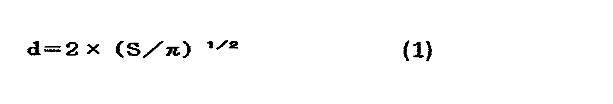

続いて、得られた正極断面のSEM-EDXについて、前記と同様に酸素マッピング及びフッ素マッピングを二値化し、酸素マッピングに対するフッ素マッピングの面積重複率A2を算出したところ39.5%であった。 [Positive electrode cross section SEM and EDX measurement]
A 1 cm × 1 cm piece is cut out from the positive electrode sample 1, and a cross section perpendicular to the surface direction of the positive electrode sample 1 is used under the conditions of an acceleration voltage of 4 kV and a beam diameter of 500 μm, using SM-09020CP manufactured by JEOL. Produced. Then, positive electrode cross section SEM and EDX were measured by the above-mentioned method.
X 1 and Y 1 were calculated by analyzing an image obtained from the measured positive electrode cross section SEM and EDX using image analysis software (ImageJ). With respect to the obtained oxygen mapping, particles containing 50% or more of bright areas binarized on the basis of the average value of luminance values are particles X of a lithium compound, and the other particles are particles Y of a positive electrode active material, For all the X and Y particles observed in the cross-sectional SEM image, the cross-sectional area S was determined, and the particle diameter d calculated by the following formula (1) was determined. (The circumference ratio is π.)
Subsequently, regarding the SEM-EDX of the obtained positive electrode cross section, the oxygen mapping and the fluorine mapping were binarized in the same manner as described above, and the area overlap ratio A 2 of the fluorine mapping with respect to the oxygen mapping was calculated to be 39.5%. .
前記得られた正極試料1を5cm×5cmの大きさ(重量0.256g)に切り出し、20gのメタノールに浸し、容器に蓋をして25℃環境下、3日間静置した。その後正極を取り出し、120℃、5kPaの条件にて10時間真空乾燥した。この時の正極重量M0は0.250gであり、洗浄後のメタノール溶液について、予め検量線を作成した条件にてGC/MSを測定し、ジエチルカーボネートの存在量が1%未満であることを確認した。続いて、25.00gの蒸留水に正極を含浸させ、容器に蓋をして45℃環境下、3日間静置した。その後正極を取り出し、150℃、3kPaの条件にて12時間真空乾燥した。この時の正極重量M1は0.236gであり、洗浄後の蒸留水について、予め検量線を作成した条件にてGC/MSを測定し、メタノールの存在量が1%未満であることを確認した。その後、スパチュラ、ブラシ、刷毛を用いて正極集電体上の活物質層を取り除き、正極集電体の重量M2を測定したところ0.099gであった。(4)式に従い正極中の炭酸リチウム量Zを定量したところ9.3質量%であった。 <Quantitative determination of lithium compounds>
The obtained positive electrode sample 1 was cut into a size of 5 cm × 5 cm (weight: 0.256 g), immersed in 20 g of methanol, covered with a container, and left to stand in a 25 ° C. environment for 3 days. Thereafter, the positive electrode was taken out and vacuum-dried at 120 ° C. and 5 kPa for 10 hours. The positive electrode weight M 0 at this time is 0.250 g, and GC / MS is measured under the conditions in which a calibration curve has been prepared in advance for the washed methanol solution, and the presence of diethyl carbonate is less than 1%. confirmed. Subsequently, 25.00 g of distilled water was impregnated with the positive electrode, and the container was covered and allowed to stand in a 45 ° C. environment for 3 days. Thereafter, the positive electrode was taken out and vacuum-dried at 150 ° C. and 3 kPa for 12 hours. The positive electrode weight M 1 at this time is 0.236 g, and GC / MS is measured under the conditions in which a calibration curve has been prepared in advance for the distilled water after washing, and it is confirmed that the amount of methanol present is less than 1%. did. Thereafter, the active material layer on the positive electrode current collector was removed using a spatula, a brush, and a brush, and the weight M 2 of the positive electrode current collector was measured to be 0.099 g. When the amount of lithium carbonate Z in the positive electrode was quantified according to the formula (4), it was 9.3% by mass.
非水系リチウム蓄電素子の充電を、電流値100mAで電圧4.6Vに到達するまで定電流充電を行った後、続けて4.6V定電圧充電を40時間継続する手法により初期充電を行い、負極にリチウムドープを行ったこと以外は実施例1と同様の方法で非水系リチウム蓄電素子を作製した。
<実施例3>
非水系リチウム蓄電素子の充電を、電流値200mAで電圧4.3Vに到達するまで定電流充電を行った後、続けて4.3V定電圧充電を10時間継続する手法により初期充電を行い、負極にリチウムドープを行ったこと以外は実施例1と同様の方法で非水系リチウム蓄電素子を作製した。
<実施例4>
炭酸リチウムの粉砕を、液体窒素で-196℃に冷却化した後、φ1.0mmのジルコニアビーズを用い、周速10.0m/sにて10分間粉砕したこと以外は実施例1と同様の方法で非水系リチウム蓄電素子を作製した。
<実施例5>
炭酸リチウムの粉砕を、液体窒素で-196℃に冷却化した後、φ1.0mmのジルコニアビーズを用い、周速10.0m/sにて5分間粉砕したこと以外は実施例1と同様の方法で非水系リチウム蓄電素子を作製した。
<実施例6>
炭酸リチウムの粉砕を、液体窒素で-196℃に冷却化した後、φ1.0mmのジルコニアビーズを用い、周速10.0m/sにて3分間粉砕したこと以外は実施例1と同様の方法で非水系リチウム蓄電素子を作製した。 <Example 2>
After charging the non-aqueous lithium storage element at a current value of 100 mA until the voltage reaches 4.6V, the initial charge is performed by a method in which 4.6V constant voltage charging is continued for 40 hours. A non-aqueous lithium electricity storage device was produced in the same manner as in Example 1 except that lithium doping was performed on.
<Example 3>
After charging the non-aqueous lithium storage element at a current value of 200 mA until the voltage reaches 4.3 V, the initial charging is performed by a method in which 4.3 V constant voltage charging is continued for 10 hours. A non-aqueous lithium electricity storage device was produced in the same manner as in Example 1 except that lithium doping was performed on.
<Example 4>
The same method as in Example 1 except that the lithium carbonate was pulverized with liquid nitrogen to -196 ° C and then pulverized for 10 minutes at a peripheral speed of 10.0 m / s using zirconia beads having a diameter of 1.0 mm. Thus, a non-aqueous lithium storage element was produced.
<Example 5>
The same method as in Example 1, except that lithium carbonate was cooled to −196 ° C. with liquid nitrogen and then pulverized at a peripheral speed of 10.0 m / s for 5 minutes using zirconia beads of φ1.0 mm. Thus, a non-aqueous lithium storage element was produced.
<Example 6>
The same method as in Example 1 except that the lithium carbonate was pulverized with liquid nitrogen to -196 ° C and then pulverized for 3 minutes at a peripheral speed of 10.0 m / s using zirconia beads having a diameter of 1.0 mm. Thus, a non-aqueous lithium storage element was produced.
炭酸リチウムの粉砕を、液体窒素で-196℃に冷却化した後、φ1.0mmのジルコニアビーズを用い、周速10.0m/sにて20分間粉砕し、非水系リチウム蓄電素子の充電を、45℃環境下、電流値200mAで電圧4.5Vに到達するまで定電流充電を行った後、続けて4.5V定電圧充電を20時間継続する手法により初期充電を行い、負極にリチウムドープを行ったこと以外は実施例1と同様の方法で非水系リチウム蓄電素子を作製した。
<実施例8>
非水系リチウム蓄電素子の充電を、電流値200mAで電圧4.3Vに到達するまで定電流充電を行った後、続けて4.3V定電圧充電を10時間継続する手法により初期充電を行い、負極にリチウムドープを行ったこと以外は実施例7と同様の方法で非水系リチウム蓄電素子を作製した。
<実施例9>
非水系リチウム蓄電素子の充電を、電流値200mAで電圧4.3Vに到達するまで定電流充電を行った後、続けて4.5V定電圧充電を5時間継続する手法により初期充電を行い、負極にリチウムドープを行ったこと以外は実施例7と同様の方法で非水系リチウム蓄電素子を作製した。 <Example 7>
Lithium carbonate pulverization was cooled to −196 ° C. with liquid nitrogen, and then pulverized at a peripheral speed of 10.0 m / s for 20 minutes using φ1.0 mm zirconia beads to charge the non-aqueous lithium storage element. In a 45 ° C environment, after constant current charging until reaching a voltage of 4.5 V at a current value of 200 mA, initial charging is performed by a method of continuing 4.5 V constant voltage charging for 20 hours, and lithium doping is applied to the negative electrode. A non-aqueous lithium storage element was produced in the same manner as in Example 1 except that it was performed.
<Example 8>
After charging the non-aqueous lithium storage element at a current value of 200 mA until the voltage reaches 4.3 V, the initial charging is performed by a method in which 4.3 V constant voltage charging is continued for 10 hours. A non-aqueous lithium electricity storage device was produced in the same manner as in Example 7 except that lithium doping was performed on.
<Example 9>
After charging the non-aqueous lithium storage element at a current value of 200 mA until the voltage reaches 4.3 V, the initial charging is performed by a method in which 4.5 V constant voltage charging is continued for 5 hours. A non-aqueous lithium electricity storage device was produced in the same manner as in Example 7 except that lithium doping was performed on.
炭酸リチウムの粉砕を、液体窒素で-196℃に冷却化した後、φ1.0mmのジルコニアビーズを用い、周速10.0m/sにて5分間粉砕したこと以外は実施例7と同様の方法で非水系リチウム蓄電素子を作製した。
<実施例11>
非水系リチウム蓄電素子の充電を、電流値200mAで電圧4.3Vに到達するまで定電流充電を行った後、続けて4.3V定電圧充電を2時間継続する手法により初期充電を行い、負極にリチウムドープを行ったこと以外は実施例10と同様の方法で非水系リチウム蓄電素子を作製した。
<実施例12>
非水系リチウム蓄電素子の充電を、電流値200mAで電圧4.5Vに到達するまで定電流充電を行った後、続けて4.5V定電圧充電を6時間継続する手法により初期充電を行い、負極にリチウムドープを行ったこと以外は実施例10と同様の方法で非水系リチウム蓄電素子を作製した。
<実施例13>
非水系リチウム蓄電素子の充電を、電流値200mAで電圧4.5Vに到達するまで定電流充電を行った後、続けて4.5V定電圧充電を1時間継続する手法により初期充電を行い、負極にリチウムドープを行ったこと以外は実施例10と同様の方法で非水系リチウム蓄電素子を作製した。
<実施例14>
非水系リチウム蓄電素子の充電を、電流値100mAで電圧4.2Vに到達するまで定電流充電を行った後、続けて4.2V定電圧充電を1時間継続する手法により初期充電を行い、負極にリチウムドープを行ったこと以外は実施例10と同様の方法で非水系リチウム蓄電素子を作製した。 <Example 10>
The same method as in Example 7, except that lithium carbonate was pulverized with liquid nitrogen to -196 ° C. and then pulverized with a zirconia bead of φ1.0 mm for 5 minutes at a peripheral speed of 10.0 m / s. Thus, a non-aqueous lithium storage element was produced.
<Example 11>
After charging the non-aqueous lithium storage element at a current value of 200 mA until the voltage reaches 4.3 V, the initial charging is performed by a method in which 4.3 V constant voltage charging is continued for 2 hours. A non-aqueous lithium electricity storage device was produced in the same manner as in Example 10 except that lithium doping was performed on.
<Example 12>
After charging the non-aqueous lithium storage element at a current value of 200 mA until the voltage reaches 4.5 V, the initial charge is performed by a method of continuing 4.5 V constant voltage charging for 6 hours. A non-aqueous lithium electricity storage device was produced in the same manner as in Example 10 except that lithium doping was performed on.
<Example 13>
After charging the non-aqueous lithium storage element at a current value of 200 mA until the voltage reaches 4.5 V, the initial charge is performed by a method in which the 4.5 V constant voltage charging is continued for 1 hour. A non-aqueous lithium electricity storage device was produced in the same manner as in Example 10 except that lithium doping was performed on.
<Example 14>
After charging the non-aqueous lithium storage element at a current value of 100 mA until the voltage reaches 4.2 V, the initial charge is performed by a method in which 4.2 V constant voltage charging is continued for 1 hour. A non-aqueous lithium electricity storage device was produced in the same manner as in Example 10 except that lithium doping was performed on.
炭酸リチウムの粉砕を、25℃環境下、φ1.0mmのジルコニアビーズを用い、周速10.0m/sにて5分間粉砕したこと以外は実施例1と同様の方法で非水系リチウム蓄電素子を作製した。
<比較例2>
非水系リチウム蓄電素子の充電を、電流値100mAで電圧4.6Vに到達するまで定電流充電を行った後、続けて4.6V定電圧充電を40時間継続する手法により初期充電を行い、負極にリチウムドープを行ったこと以外は比較例1と同様の方法で非水系リチウム蓄電素子を作製した。
<比較例3>
非水系リチウム蓄電素子の充電を、電流値200mAで電圧4.3Vに到達するまで定電流充電を行った後、続けて4.3V定電圧充電を10時間継続する手法により初期充電を行い、負極にリチウムドープを行ったこと以外は比較例1と同様の方法で非水系リチウム蓄電素子を作製した。 <Comparative Example 1>
A non-aqueous lithium storage element was obtained in the same manner as in Example 1 except that lithium carbonate was pulverized in a 25 ° C. environment using φ1.0 mm zirconia beads at a peripheral speed of 10.0 m / s for 5 minutes. Produced.
<Comparative Example 2>
After charging the non-aqueous lithium storage element at a current value of 100 mA until the voltage reaches 4.6V, the initial charge is performed by a method in which 4.6V constant voltage charging is continued for 40 hours. A non-aqueous lithium electricity storage device was produced in the same manner as in Comparative Example 1 except that lithium doping was performed on the substrate.
<Comparative Example 3>
After charging the non-aqueous lithium storage element at a current value of 200 mA until the voltage reaches 4.3 V, the initial charging is performed by a method in which 4.3 V constant voltage charging is continued for 10 hours. A non-aqueous lithium electricity storage device was produced in the same manner as in Comparative Example 1 except that lithium doping was performed on the substrate.
炭酸リチウムの粉砕を、25℃環境下、φ1.0mmのジルコニアビーズを用い、周速10.0m/sにて2分間粉砕したこと以外は実施例1と同様の方法で非水系リチウム蓄電素子を作製した。
<比較例5>
非水系リチウム蓄電素子の充電を、電流値200mAで電圧4.3Vに到達するまで定電流充電を行った後、続けて4.3V定電圧充電を10時間継続する手法により初期充電を行い、負極にリチウムドープを行ったこと以外は比較例4と同様の方法で非水系リチウム蓄電素子を作製した。
<比較例6>
非水系リチウム蓄電素子の充電を、電流値200mAで電圧4.3Vに到達するまで定電流充電を行った後、続けて4.3V定電圧充電を10時間継続する手法により初期充電を行い、負極にリチウムドープを行ったこと以外は比較例4と同様の方法で非水系リチウム蓄電素子を作製した。
<比較例7>
非水系リチウム蓄電素子の充電を、45℃環境下、電流値200mAで電圧4.5Vに到達するまで定電流充電を行った後、続けて4.5V定電圧充電を20時間継続する手法により初期充電を行い、負極にリチウムドープを行ったこと以外は比較例1と同様の方法で非水系リチウム蓄電素子を作製した。 <Comparative Example 4>
A non-aqueous lithium storage element was obtained in the same manner as in Example 1 except that lithium carbonate was pulverized for 2 minutes at a peripheral speed of 10.0 m / s using φ1.0 mm zirconia beads in a 25 ° C. environment. Produced.
<Comparative Example 5>
After charging the non-aqueous lithium storage element at a current value of 200 mA until the voltage reaches 4.3 V, the initial charging is performed by a method in which 4.3 V constant voltage charging is continued for 10 hours. A non-aqueous lithium storage element was produced in the same manner as in Comparative Example 4 except that lithium doping was performed.
<Comparative Example 6>
After charging the non-aqueous lithium storage element at a current value of 200 mA until the voltage reaches 4.3 V, the initial charging is performed by a method in which 4.3 V constant voltage charging is continued for 10 hours. A non-aqueous lithium storage element was produced in the same manner as in Comparative Example 4 except that lithium doping was performed.
<Comparative Example 7>
The non-aqueous lithium storage element is initially charged in a 45 ° C environment by constant current charging until reaching a voltage of 4.5 V at a current value of 200 mA, followed by 4.5 V constant voltage charging for 20 hours. A non-aqueous lithium storage element was produced in the same manner as in Comparative Example 1 except that the battery was charged and lithium was doped into the negative electrode.
非水系リチウム蓄電素子の充電を、電流値100mAで電圧4.6Vに到達するまで定電流充電を行った後、続けて4.6V定電圧充電を40時間継続する手法により初期充電を行い、負極にリチウムドープを行ったこと以外は比較例7と同様の方法で非水系リチウム蓄電素子を作製した。
<比較例9>
非水系リチウム蓄電素子の充電を、電流値200mAで電圧4.3Vに到達するまで定電流充電を行った後、続けて4.3V定電圧充電を10時間継続する手法により初期充電を行い、負極にリチウムドープを行ったこと以外は比較例7と同様の方法で非水系リチウム蓄電素子を作製した。
<比較例10>
非水系リチウム蓄電素子の充電を、0℃環境下、電流値200mAで電圧4.5Vに到達するまで定電流充電を行った後、続けて4.5V定電圧充電を20時間継続する手法により初期充電を行い、負極にリチウムドープを行ったこと以外は比較例1と同様の方法で非水系リチウム蓄電素子を作製した。
<比較例11>
非水系リチウム蓄電素子の充電を、電流値100mAで電圧4.6Vに到達するまで定電流充電を行った後、続けて4.6V定電圧充電を40時間継続する手法により初期充電を行い、負極にリチウムドープを行ったこと以外は比較例10と同様の方法で非水系リチウム蓄電素子を作製した。
<比較例12>
非水系リチウム蓄電素子の充電を、電流値200mAで電圧4.3Vに到達するまで定電流充電を行った後、続けて4.3V定電圧充電を10時間継続する手法により初期充電を行い、負極にリチウムドープを行ったこと以外は比較例10と同様の方法で非水系リチウム蓄電素子を作製した。
実施例1~14、比較例1~12の非水系リチウム蓄電素子の評価結果を表1に示す。 <Comparative Example 8>
After charging the non-aqueous lithium storage element at a current value of 100 mA until the voltage reaches 4.6V, the initial charge is performed by a method in which 4.6V constant voltage charging is continued for 40 hours. A non-aqueous lithium electricity storage device was produced in the same manner as in Comparative Example 7, except that lithium doping was performed on.
<Comparative Example 9>
After charging the non-aqueous lithium storage element at a current value of 200 mA until the voltage reaches 4.3 V, the initial charging is performed by a method in which 4.3 V constant voltage charging is continued for 10 hours. A non-aqueous lithium electricity storage device was produced in the same manner as in Comparative Example 7, except that lithium doping was performed on.
<Comparative Example 10>
The nonaqueous lithium storage element is initially charged by constant current charging until reaching a voltage of 4.5 V at a current value of 200 mA in a 0 ° C. environment, followed by a method of continuing 4.5 V constant voltage charging for 20 hours. A non-aqueous lithium storage element was produced in the same manner as in Comparative Example 1 except that the battery was charged and lithium was doped into the negative electrode.
<Comparative Example 11>
After charging the non-aqueous lithium storage element at a current value of 100 mA until the voltage reaches 4.6V, the initial charge is performed by a method in which 4.6V constant voltage charging is continued for 40 hours. A non-aqueous lithium electricity storage device was produced in the same manner as in Comparative Example 10 except that lithium doping was performed on.
<Comparative Example 12>
After charging the non-aqueous lithium storage element at a current value of 200 mA until the voltage reaches 4.3 V, the initial charging is performed by a method in which 4.3 V constant voltage charging is continued for 10 hours. A non-aqueous lithium electricity storage device was produced in the same manner as in Comparative Example 10 except that lithium doping was performed on.
Table 1 shows the evaluation results of the nonaqueous lithium storage elements of Examples 1 to 14 and Comparative Examples 1 to 12.
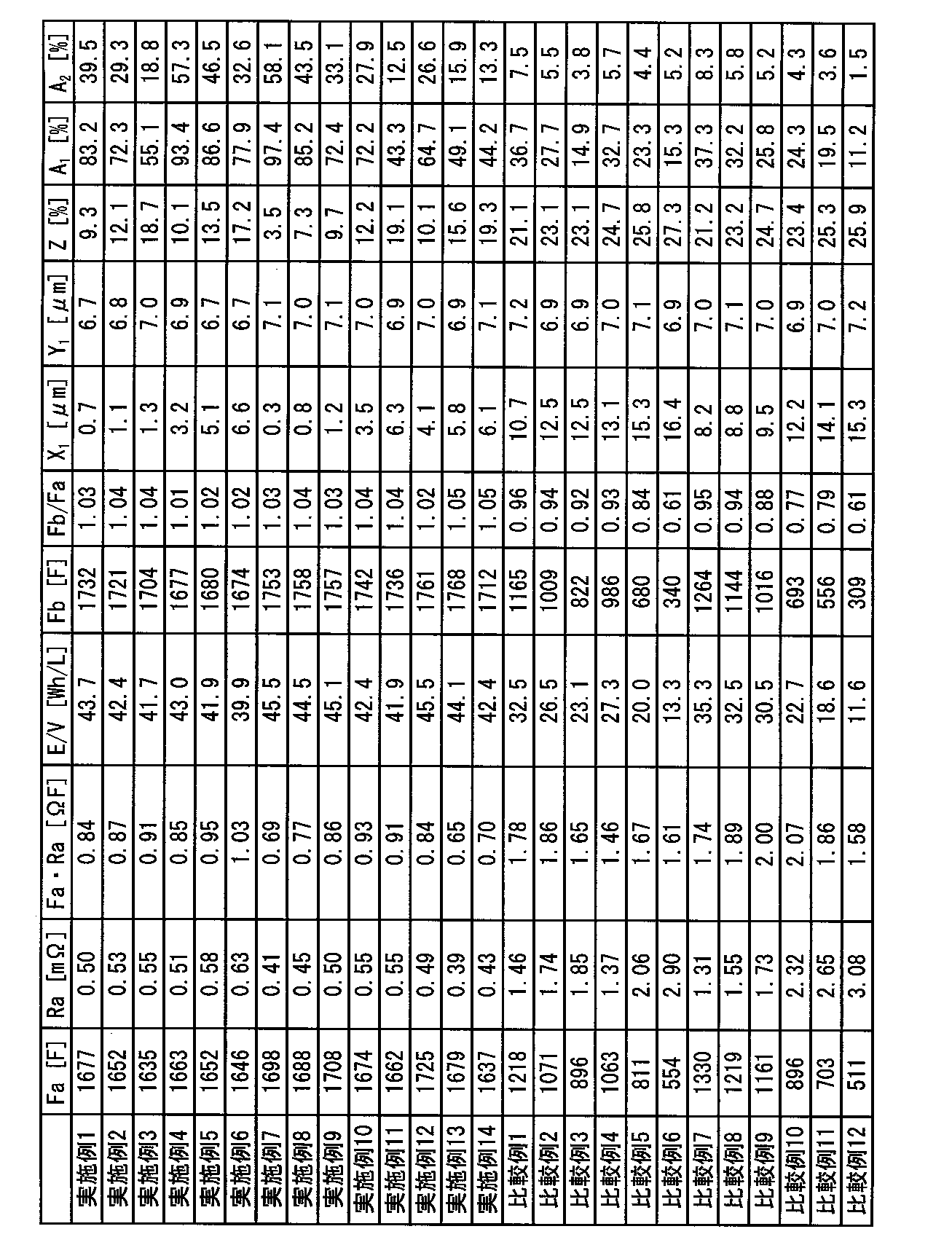
<炭酸リチウムの粉砕>
平均粒子径53μmの炭酸リチウム200gを、アイメックス社製の粉砕機(液体窒素ビーズミルLNM)を用い、液体窒素で-196℃に冷却化した後、φ1.0mmのジルコニアビーズを用い、周速10.0m/sにて30分間粉砕した。-196℃で熱変性を防止し、脆性破壊することにより得られた炭酸リチウム2について平均粒子径を測定したところ3.8μmであった。
<正極前駆体の製造>
前記活性炭1aを正極活物質として用い、前記炭酸リチウム2をリチウム化合物として正極前駆体を製造した。
活性炭1aを55.5質量部、炭酸リチウム2を32.0質量部、ケッチェンブラックを3.0質量部、PVP(ポリビニルピロリドン)を1.5質量部、及びPVDF(ポリフッ化ビニリデン)を8.0質量部、並びにNMP(N-メチルピロリドン)を混合し、それをPRIMIX社製の薄膜旋回型高速ミキサーフィルミックスを用いて、周速17m/sの条件で分散して塗工液を得た。得られた塗工液の粘度(ηb)及びTI値を東機産業社のE型粘度計TVE-35Hを用いて測定した。その結果、粘度(ηb)は2,100mPa・s、TI値は3.7であった。また、得られた塗工液の分散度をヨシミツ精機社製の粒ゲージを用いて測定した。その結果、粒度は42μmであった。前記塗工液を東レエンジニアリング社製のダイコーターを用いて厚さ15μmのアルミニウム箔の片面又は両面に塗工速度1m/sの条件で塗工し、乾燥温度120℃で乾燥して正極前駆体2(片面)及び正極前駆体2(両面)を得た。得られた正極前駆体2(片面)及び正極前駆体2(両面)についてロールプレス機を用いて圧力6kN/cm、プレス部の表面温度25℃の条件でプレスを実施した。前記で得られた正極前駆体2(片面)及び正極前駆体2(両面)の正極活物質層の膜厚を小野計器社製膜厚計Linear Gauge Sensor GS-551を用いて、正極前駆体2の任意の10か所で測定した厚さの平均値から、アルミニウム箔の厚さを引いて求めた。その結果、正極活物質層の膜厚は片面あたりの厚さは58μmであった。 <Example 15>
<Lithium carbonate grinding>
200 g of lithium carbonate having an average particle size of 53 μm was cooled to −196 ° C. with liquid nitrogen using a crusher (liquid nitrogen bead mill LNM) manufactured by Imex Co., Ltd., and zirconia beads with φ1.0 mm were used. It grind | pulverized for 30 minutes at 0 m / s. The average particle diameter of
<Production of positive electrode precursor>
A positive electrode precursor was manufactured using the activated carbon 1a as a positive electrode active material and the
55.5 parts by mass of activated carbon 1a, 32.0 parts by mass of
市販の人造黒鉛のBET比表面積及び細孔分布を、ユアサアイオニクス社製細孔分布測定装置(AUTOSORB-1 AS-1-MP)を用いて、上述した方法によって測定した。その結果、BET比表面積は3.1m2/g、平均粒子径は4.8μmであった。
この人造黒鉛300gをステンレススチールメッシュ製の籠に入れ、石炭系ピッチ(軟化点:50℃)30gを入れたステンレス製バットの上に置き、両者を電気炉(炉内有効寸法300mm×300mm×300mm)内に設置して、熱反応を行うことにより、複合多孔質炭素材料2a1を得た。この熱処理は窒素雰囲気下で行い、1000℃まで12時間で昇温し、同温度で5時間保持する方法によった。続いて自然冷却により60℃まで冷却した後、複合炭素材料2a1を炉から取り出した。
得られた複合炭素材料2a1について、前記と同様の方法でBET比表面積及び細孔分布を測定した。その結果、BET比表面積は6.1m2/g、平均粒子径は4.9μmであった。また、複合炭素材料2a1において、石炭系ピッチ由来の炭素質材料の活性炭に対する質量比率は2.0%であった。 <Preparation of Negative Electrode Active Material Preparation Example 2a 1 >
The BET specific surface area and pore distribution of commercially available artificial graphite were measured by the above-described method using a pore distribution measuring apparatus (AUTOSORB-1 AS-1-MP) manufactured by Yuasa Ionics. As a result, the BET specific surface area was 3.1 m 2 / g, and the average particle size was 4.8 μm.
300 g of this artificial graphite is placed in a stainless steel mesh basket and placed on a stainless steel bat containing 30 g of a coal-based pitch (softening point: 50 ° C.). ) was placed in, by thermal reaction, to obtain a composite porous carbon material 2a 1. This heat treatment was performed in a nitrogen atmosphere, and the temperature was raised to 1000 ° C. in 12 hours and held at that temperature for 5 hours. Subsequently, after cooling to 60 ° C. by natural cooling, the composite carbon material 2a 1 was taken out from the furnace.
The resulting composite carbon material 2a 1, was measured BET specific surface area and pore distribution in the same manner as above. As a result, the BET specific surface area was 6.1 m 2 / g, and the average particle size was 4.9 μm. Moreover, in the composite carbon material 2a 1 , the mass ratio of the carbonaceous material derived from the coal-based pitch to the activated carbon was 2.0%.
前記複合炭素材料2a1を負極活物質として用いて負極を製造した。
複合炭素材料2a1を84質量部、アセチレンブラックを10質量部、及びPVdF(ポリフッ化ビニリデン)を6質量部、並びにNMP(N-メチルピロリドン)を混合し、それをPRIMIX社製の薄膜旋回型高速ミキサーフィルミックスを用いて、周速17m/sの条件で分散して塗工液を得た。得られた塗工液の粘度(ηb)及びTI値を東機産業社のE型粘度計TVE-35Hを用いて測定した。その結果、粘度(ηb)は2,326mPa・s、TI値は2.7であった。前記塗工液を東レエンジニアリング社製のダイコーターを用いて厚さ10μmの電解銅箔の両面に塗工速度2m/sの条件で塗工し、乾燥温度120℃で乾燥して負極2を得た。得られた負極2についてロールプレス機を用いて圧力5kN/cm、プレス部の表面温度25℃の条件でプレスを実施した。前記で得られた負極2の負極活物質層の膜厚を小野計器社製膜厚計Linear Gauge Sensor GS-551を用いて、負極2の任意の10か所で測定した厚さの平均値から、銅箔の厚さを引いて求めた。その結果、負極活物質層の膜厚は片面あたりの厚さは30μmであった。
前記の方法にて単位質量当たりのリチウムイオンのドープ量を測定したところ、545mAh/gであった。
<非水系リチウム蓄電素子の作製>
正極前駆体2(片面)、正極前駆体2(両面)、及び負極2を用いたこと以外は実施例1と同様の手法にて非水系リチウム蓄電素子を作製した。 <Manufacture of negative electrode>
A negative electrode was manufactured using the composite carbon material 2a 1 as a negative electrode active material.
84 parts by mass of
When the dope amount of lithium ions per unit mass was measured by the above method, it was 545 mAh / g.
<Production of non-aqueous lithium storage element>
A non-aqueous lithium storage element was produced in the same manner as in Example 1 except that the positive electrode precursor 2 (single side), the positive electrode precursor 2 (both sides), and the
非水系リチウム蓄電素子の充電を、電流値100mAで電圧4.6Vに到達するまで定電流充電を行った後、続けて4.6V定電圧充電を40時間継続する手法により初期充電を行い、負極にリチウムドープを行ったこと以外は実施例15と同様の方法で非水系リチウム蓄電素子を作製した。
<実施例17>
非水系リチウム蓄電素子の充電を、電流値200mAで電圧4.3Vに到達するまで定電流充電を行った後、続けて4.3V定電圧充電を10時間継続する手法により初期充電を行い、負極にリチウムドープを行ったこと以外は実施例15と同様の方法で非水系リチウム蓄電素子を作製した。
<実施例18>
炭酸リチウムの粉砕を、液体窒素で-196℃に冷却化した後、φ1.0mmのジルコニアビーズを用い、周速10.0m/sにて10分間粉砕したこと以外は実施例15と同様の方法で非水系リチウム蓄電素子を作製した。
<実施例19>
炭酸リチウムの粉砕を、液体窒素で-196℃に冷却化した後、φ1.0mmのジルコニアビーズを用い、周速10.0m/sにて5分間粉砕したこと以外は実施例15と同様の方法で非水系リチウム蓄電素子を作製した。
<実施例20>
炭酸リチウムの粉砕を、液体窒素で-196℃に冷却化した後、φ1.0mmのジルコニアビーズを用い、周速10.0m/sにて3分間粉砕したこと以外は実施例15と同様の方法で非水系リチウム蓄電素子を作製した。
<実施例21>
炭酸リチウムの粉砕を、液体窒素で-196℃に冷却化した後、φ1.0mmのジルコニアビーズを用い、周速10.0m/sにて20分間粉砕し、非水系リチウム蓄電素子の充電を、45℃環境下、電流値200mAで電圧4.5Vに到達するまで定電流充電を行った後、続けて4.5V定電圧充電を20時間継続する手法により初期充電を行い、負極にリチウムドープを行ったこと以外は実施例15と同様の方法で非水系リチウム蓄電素子を作製した。 <Example 16>
After charging the non-aqueous lithium storage element at a current value of 100 mA until the voltage reaches 4.6V, the initial charge is performed by a method in which 4.6V constant voltage charging is continued for 40 hours. A non-aqueous lithium electricity storage device was produced in the same manner as in Example 15 except that lithium doping was performed on.
<Example 17>
After charging the non-aqueous lithium storage element at a current value of 200 mA until the voltage reaches 4.3 V, the initial charging is performed by a method in which 4.3 V constant voltage charging is continued for 10 hours. A non-aqueous lithium electricity storage device was produced in the same manner as in Example 15 except that lithium doping was performed on.
<Example 18>
The same method as in Example 15 except that lithium carbonate was cooled to −196 ° C. with liquid nitrogen and then pulverized for 10 minutes at a peripheral speed of 10.0 m / s using Φ1.0 mm zirconia beads. Thus, a non-aqueous lithium storage element was produced.
<Example 19>
The same method as in Example 15 except that the lithium carbonate was pulverized with liquid nitrogen to -196 ° C, and then pulverized at a peripheral speed of 10.0 m / s for 5 minutes using φ1.0 mm zirconia beads. Thus, a non-aqueous lithium storage element was produced.
<Example 20>
The same method as in Example 15 except that lithium carbonate was cooled to −196 ° C. with liquid nitrogen and then pulverized for 3 minutes at a peripheral speed of 10.0 m / s using zirconia beads of φ1.0 mm. Thus, a non-aqueous lithium storage element was produced.
<Example 21>
Lithium carbonate pulverization was cooled to −196 ° C. with liquid nitrogen, and then pulverized at a peripheral speed of 10.0 m / s for 20 minutes using φ1.0 mm zirconia beads to charge the non-aqueous lithium storage element. In a 45 ° C environment, after constant current charging until reaching a voltage of 4.5 V at a current value of 200 mA, initial charging is performed by a method of continuing 4.5 V constant voltage charging for 20 hours, and lithium doping is applied to the negative electrode. A non-aqueous lithium electricity storage device was produced in the same manner as in Example 15 except for the above.
非水系リチウム蓄電素子の充電を、電流値200mAで電圧4.3Vに到達するまで定電流充電を行った後、続けて4.3V定電圧充電を10時間継続する手法により初期充電を行い、負極にリチウムドープを行ったこと以外は実施例21と同様の方法で非水系リチウム蓄電素子を作製した。
<実施例23>
非水系リチウム蓄電素子の充電を、電流値200mAで電圧4.3Vに到達するまで定電流充電を行った後、続けて4.5V定電圧充電を5時間継続する手法により初期充電を行い、負極にリチウムドープを行ったこと以外は実施例21と同様の方法で非水系リチウム蓄電素子を作製した。
<実施例24>
炭酸リチウムの粉砕を、液体窒素で-196℃に冷却化した後、φ1.0mmのジルコニアビーズを用い、周速10.0m/sにて5分間粉砕したこと以外は実施例21と同様の方法で非水系リチウム蓄電素子を作製した。
<実施例25>
非水系リチウム蓄電素子の充電を、電流値200mAで電圧4.3Vに到達するまで定電流充電を行った後、続けて4.3V定電圧充電を2時間継続する手法により初期充電を行い、負極にリチウムドープを行ったこと以外は実施例24と同様の方法で非水系リチウム蓄電素子を作製した。
<実施例26> <Example 22>
After charging the non-aqueous lithium storage element at a current value of 200 mA until the voltage reaches 4.3 V, the initial charging is performed by a method in which 4.3 V constant voltage charging is continued for 10 hours. A non-aqueous lithium electricity storage device was produced in the same manner as in Example 21 except that lithium doping was performed on.
<Example 23>
After charging the non-aqueous lithium storage element at a current value of 200 mA until the voltage reaches 4.3 V, the initial charging is performed by a method in which 4.5 V constant voltage charging is continued for 5 hours. A non-aqueous lithium electricity storage device was produced in the same manner as in Example 21 except that lithium doping was performed on.
<Example 24>
The same method as in Example 21, except that lithium carbonate was cooled to −196 ° C. with liquid nitrogen and then pulverized at a peripheral speed of 10.0 m / s for 5 minutes using zirconia beads of φ1.0 mm. Thus, a non-aqueous lithium storage element was produced.
<Example 25>
After charging the non-aqueous lithium storage element at a current value of 200 mA until the voltage reaches 4.3 V, the initial charging is performed by a method in which 4.3 V constant voltage charging is continued for 2 hours. A non-aqueous lithium electricity storage device was produced in the same manner as in Example 24 except that lithium doping was performed on.
<Example 26>
<実施例27>
非水系リチウム蓄電素子の充電を、電流値200mAで電圧4.5Vに到達するまで定電流充電を行った後、続けて4.5V定電圧充電を1時間継続する手法により初期充電を行い、負極にリチウムドープを行ったこと以外は実施例24と同様の方法で非水系リチウム蓄電素子を作製した。
<実施例28>
非水系リチウム蓄電素子の充電を、電流値100mAで電圧4.2Vに到達するまで定電流充電を行った後、続けて4.2V定電圧充電を1時間継続する手法により初期充電を行い、負極にリチウムドープを行ったこと以外は実施例24と同様の方法で非水系リチウム蓄電素子を作製した。 After charging the non-aqueous lithium storage element at a current value of 200 mA until the voltage reaches 4.5 V, the initial charge is performed by a method of continuing 4.5 V constant voltage charging for 6 hours. A non-aqueous lithium electricity storage device was produced in the same manner as in Example 24 except that lithium doping was performed on.
<Example 27>
After charging the non-aqueous lithium storage element at a current value of 200 mA until the voltage reaches 4.5 V, the initial charge is performed by a method in which the 4.5 V constant voltage charging is continued for 1 hour. A non-aqueous lithium electricity storage device was produced in the same manner as in Example 24 except that lithium doping was performed on.
<Example 28>
After charging the non-aqueous lithium storage element at a current value of 100 mA until the voltage reaches 4.2 V, the initial charge is performed by a method in which 4.2 V constant voltage charging is continued for 1 hour. A non-aqueous lithium electricity storage device was produced in the same manner as in Example 24 except that lithium doping was performed on.
炭酸リチウムの粉砕を、25℃環境下、φ1.0mmのジルコニアビーズを用い、周速10.0m/sにて5分間粉砕したこと以外は実施例15と同様の方法で非水系リチウム蓄電素子を作製した。
<比較例14>
非水系リチウム蓄電素子の充電を、電流値100mAで電圧4.6Vに到達するまで定電流充電を行った後、続けて4.6V定電圧充電を40時間継続する手法により初期充電を行い、負極にリチウムドープを行ったこと以外は比較例13と同様の方法で非水系リチウム蓄電素子を作製した。
<比較例15>
非水系リチウム蓄電素子の充電を、電流値200mAで電圧4.3Vに到達するまで定電流充電を行った後、続けて4.3V定電圧充電を10時間継続する手法により初期充電を行い、負極にリチウムドープを行ったこと以外は比較例13と同様の方法で非水系リチウム蓄電素子を作製した。 <Comparative Example 13>
A non-aqueous lithium storage element was fabricated in the same manner as in Example 15 except that pulverization of lithium carbonate was performed for 5 minutes at a peripheral speed of 10.0 m / s using φ1.0 mm zirconia beads in a 25 ° C. environment. Produced.
<Comparative example 14>
After charging the non-aqueous lithium storage element at a current value of 100 mA until the voltage reaches 4.6V, the initial charge is performed by a method in which 4.6V constant voltage charging is continued for 40 hours. A non-aqueous lithium electricity storage device was produced in the same manner as in Comparative Example 13 except that lithium doping was performed on.
<Comparative Example 15>
After charging the non-aqueous lithium storage element at a current value of 200 mA until the voltage reaches 4.3 V, the initial charging is performed by a method in which 4.3 V constant voltage charging is continued for 10 hours. A non-aqueous lithium electricity storage device was produced in the same manner as in Comparative Example 13 except that lithium doping was performed on.
炭酸リチウムの粉砕を、25℃環境下、φ1.0mmのジルコニアビーズを用い、周速10.0m/sにて2分間粉砕したこと以外は実施例13と同様の方法で非水系リチウム蓄電素子を作製した。
<比較例17>
非水系リチウム蓄電素子の充電を、電流値200mAで電圧4.3Vに到達するまで定電流充電を行った後、続けて4.3V定電圧充電を10時間継続する手法により初期充電を行い、負極にリチウムドープを行ったこと以外は比較例16と同様の方法で非水系リチウム蓄電素子を作製した。
<比較例18>
非水系リチウム蓄電素子の充電を、電流値200mAで電圧4.3Vに到達するまで定電流充電を行った後、続けて4.3V定電圧充電を10時間継続する手法により初期充電を行い、負極にリチウムドープを行ったこと以外は比較例16と同様の方法で非水系リチウム蓄電素子を作製した。
<比較例19>
非水系リチウム蓄電素子の充電を、45℃環境下、電流値200mAで電圧4.5Vに到達するまで定電流充電を行った後、続けて4.5V定電圧充電を20時間継続する手法により初期充電を行い、負極にリチウムドープを行ったこと以外は比較例13と同様の方法で非水系リチウム蓄電素子を作製した。
<比較例20>
非水系リチウム蓄電素子の充電を、電流値100mAで電圧4.6Vに到達するまで定電流充電を行った後、続けて4.6V定電圧充電を40時間継続する手法により初期充電を行い、負極にリチウムドープを行ったこと以外は比較例19と同様の方法で非水系リチウム蓄電素子を作製した。 <Comparative Example 16>
A non-aqueous lithium storage element was manufactured in the same manner as in Example 13 except that lithium carbonate was pulverized in a 25 ° C. environment using φ1.0 mm zirconia beads at a peripheral speed of 10.0 m / s for 2 minutes. Produced.
<Comparative Example 17>
After charging the non-aqueous lithium storage element at a current value of 200 mA until the voltage reaches 4.3 V, the initial charging is performed by a method in which 4.3 V constant voltage charging is continued for 10 hours. A non-aqueous lithium electricity storage device was produced in the same manner as in Comparative Example 16, except that lithium doping was performed on.
<Comparative Example 18>
After charging the non-aqueous lithium storage element at a current value of 200 mA until the voltage reaches 4.3 V, the initial charging is performed by a method in which 4.3 V constant voltage charging is continued for 10 hours. A non-aqueous lithium electricity storage device was produced in the same manner as in Comparative Example 16, except that lithium doping was performed on.
<Comparative Example 19>
The non-aqueous lithium storage element is initially charged in a 45 ° C environment by constant current charging until reaching a voltage of 4.5 V at a current value of 200 mA, followed by 4.5 V constant voltage charging for 20 hours. A non-aqueous lithium storage element was produced in the same manner as in Comparative Example 13 except that the battery was charged and lithium was doped into the negative electrode.
<Comparative Example 20>
After charging the non-aqueous lithium storage element at a current value of 100 mA until the voltage reaches 4.6V, the initial charge is performed by a method in which 4.6V constant voltage charging is continued for 40 hours. A non-aqueous lithium electricity storage device was produced in the same manner as in Comparative Example 19 except that lithium doping was performed on.
非水系リチウム蓄電素子の充電を、電流値200mAで電圧4.3Vに到達するまで定電流充電を行った後、続けて4.3V定電圧充電を10時間継続する手法により初期充電を行い、負極にリチウムドープを行ったこと以外は比較例19と同様の方法で非水系リチウム蓄電素子を作製した。
<比較例22>
非水系リチウム蓄電素子の充電を、0℃環境下、電流値200mAで電圧4.5Vに到達するまで定電流充電を行った後、続けて4.5V定電圧充電を20時間継続する手法により初期充電を行い、負極にリチウムドープを行ったこと以外は比較例13と同様の方法で非水系リチウム蓄電素子を作製した。
<比較例23>
非水系リチウム蓄電素子の充電を、電流値100mAで電圧4.6Vに到達するまで定電流充電を行った後、続けて4.6V定電圧充電を40時間継続する手法により初期充電を行い、負極にリチウムドープを行ったこと以外は比較例22と同様の方法で非水系リチウム蓄電素子を作製した。
<比較例24>
非水系リチウム蓄電素子の充電を、電流値200mAで電圧4.3Vに到達するまで定電流充電を行った後、続けて4.3V定電圧充電を10時間継続する手法により初期充電を行い、負極にリチウムドープを行ったこと以外は比較例22と同様の方法で非水系リチウム蓄電素子を作製した。
実施例15~28、比較例13~24の非水系リチウム蓄電素子の評価結果を表2に示す。 <Comparative Example 21>
After charging the non-aqueous lithium storage element at a current value of 200 mA until the voltage reaches 4.3 V, the initial charging is performed by a method in which 4.3 V constant voltage charging is continued for 10 hours. A non-aqueous lithium electricity storage device was produced in the same manner as in Comparative Example 19 except that lithium doping was performed on.
<Comparative Example 22>
The nonaqueous lithium storage element is initially charged by constant current charging until reaching a voltage of 4.5 V at a current value of 200 mA in a 0 ° C. environment, followed by a method of continuing 4.5 V constant voltage charging for 20 hours. A non-aqueous lithium storage element was produced in the same manner as in Comparative Example 13 except that the battery was charged and lithium was doped into the negative electrode.
<Comparative Example 23>
After charging the non-aqueous lithium storage element at a current value of 100 mA until the voltage reaches 4.6V, the initial charge is performed by a method in which 4.6V constant voltage charging is continued for 40 hours. A non-aqueous lithium electricity storage element was produced in the same manner as in Comparative Example 22 except that lithium doping was performed on.
<Comparative Example 24>
After charging the non-aqueous lithium storage element at a current value of 200 mA until the voltage reaches 4.3 V, the initial charging is performed by a method in which 4.3 V constant voltage charging is continued for 10 hours. A non-aqueous lithium electricity storage element was produced in the same manner as in Comparative Example 22 except that lithium doping was performed on.
Table 2 shows the evaluation results of the non-aqueous lithium storage elements of Examples 15 to 28 and Comparative Examples 13 to 24.
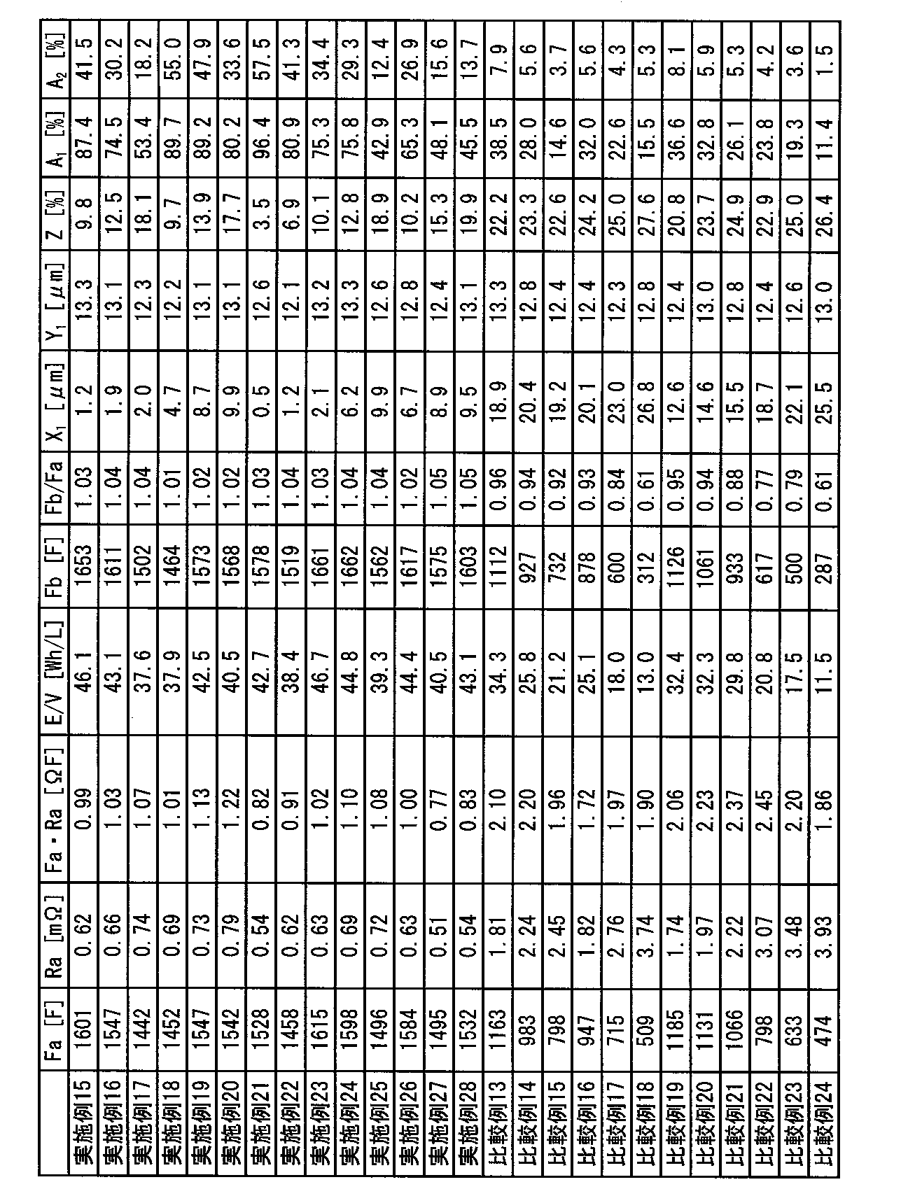
炭酸リチウムの粉砕を-196℃という極低温の条件で粉砕したことにより、粉砕時の温度上昇の影響を受けず、炭酸リチウム粒子表面の欠陥生成を抑制することができたと考えられる。その結果、炭酸リチウム粒子の再凝集を抑制でき、炭酸リチウムの粒子が微細化された状態で正極活物質層中に分散し、正極活物質の隙間に炭酸リチウムが存在することで正極活物質間の電子伝導が確保され、高出力な非水系リチウム蓄電素子が得られたと考えられる。更に、炭酸リチウム粒子の表面で電解質であるLiPF6が分解して生じるフッ素化合物が万遍なく堆積することができたため、高負荷充放電特性が改善したと考えられる。 <Evaluation of Examples 1 to 28 and Comparative Examples 1 to 24>
It is considered that the formation of defects on the surface of the lithium carbonate particles could be suppressed without being affected by the temperature increase during the pulverization by pulverizing the lithium carbonate under the extremely low temperature condition of -196 ° C. As a result, reaggregation of the lithium carbonate particles can be suppressed, and the lithium carbonate particles are dispersed in the positive electrode active material layer in a finely divided state. It is considered that a high-power non-aqueous lithium storage element was obtained. Furthermore, it was considered that the high load charge / discharge characteristics were improved because the fluorine compound produced by the decomposition of LiPF 6 as the electrolyte could be uniformly deposited on the surface of the lithium carbonate particles.
平均粒子径73μmの水酸化リチウム200gを、アイメックス社製の粉砕機(液体窒素ビーズミルLNM)を用い、液体窒素で-196℃に冷却化した後、ドライアイスビーズを用い、周速10.0m/sにて60分間粉砕した。-196℃で熱変性を防止し、脆性破壊することにより得られた水酸化リチウム1について平均粒子径を測定したところ2.4μmであった。
前記得られた水酸化リチウム1を用いたこと以外は実施例1と同様の手法にて非水系リチウム蓄電素子を作製した。得られた非水系リチウム蓄電素子を実施例1と同様に評価したところ、Faは1540F、Raは0.62mΩ、Fa・Raは0.95ΩF、E/Vは38.2Wh/L、Fbは1588F、Fb/Faは1.03、X1は0.5μm、Y1は7.1μm、Zは10.1%、A1は79.3%、A2は36.3%であった。
<比較例25>
水酸化リチウムの粉砕を、25℃環境下、φ1.0mmのジルコニアビーズを用い、周速10.0m/sにて5分間粉砕し、リチウム化合物として用いたこと以外は実施例29と同様の方法で非水系リチウム蓄電素子を作製した。得られた非水系リチウム蓄電素子を実施例1と同様に評価したところ、Faは845F、Raは2.54mΩ、Fa・Raは2.15ΩF、E/Vは25.2Wh/L、Fbは808F、Fb/Faは0.97、X1は9.6μm、Y1は7.1μm、Zは22.1%、A1は31.3%、A2は6.0%であった。
<実施例30>
平均粒子径83μmの酸化リチウム200gを、アイメックス社製の粉砕機(液体窒素ビーズミルLNM)を用い、液体窒素で-196℃に冷却化した後、ドライアイスビーズを用い、周速10.0m/sにて120分間粉砕した。-196℃で熱変性を防止し、脆性破壊することにより得られた酸化リチウム1について平均粒子径を測定したところ3.5μmであった。
前記得られた酸化リチウム1を用いたこと以外は実施例1と同様の手法にて非水系リチウム蓄電素子を作製した。得られた非水系リチウム蓄電素子を実施例1と同様に評価したところ、Faは1620F、Raは0.59mΩ、Fa・Raは0.96ΩF、E/Vは40.1Wh/L、Fbは1657F、Fb/Faは1.02、X1は1.4μm、Y1は7.0μm、Zは12.1%、A1は82.4%、A2は42.2%であった。 <Example 29>
200 g of lithium hydroxide having an average particle size of 73 μm was cooled to −196 ° C. with liquid nitrogen using a crusher (liquid nitrogen bead mill LNM) manufactured by Imex Co., Ltd., and then peripheral speed 10.0 m / Milled for 60 minutes in s. The average particle diameter of lithium hydroxide 1 obtained by preventing thermal denaturation at −196 ° C. and brittle fracture was measured to be 2.4 μm.
A non-aqueous lithium electricity storage device was produced in the same manner as in Example 1 except that the obtained lithium hydroxide 1 was used. The obtained non-aqueous lithium electricity storage element was evaluated in the same manner as in Example 1. As a result, Fa was 1540F, Ra was 0.62 mΩ, Fa · Ra was 0.95ΩF, E / V was 38.2 Wh / L, and Fb was 1588F. Fb / Fa was 1.03, X 1 was 0.5 μm, Y 1 was 7.1 μm, Z was 10.1%, A 1 was 79.3%, and A 2 was 36.3%.
<Comparative Example 25>
The same method as in Example 29, except that lithium hydroxide was pulverized in a 25 ° C. environment using φ1.0 mm zirconia beads at a peripheral speed of 10.0 m / s for 5 minutes and used as a lithium compound. Thus, a non-aqueous lithium storage element was produced. The obtained non-aqueous lithium electricity storage device was evaluated in the same manner as in Example 1. As a result, Fa was 845F, Ra was 2.54 mΩ, Fa · Ra was 2.15ΩF, E / V was 25.2 Wh / L, and Fb was 808F. Fb / Fa was 0.97, X 1 was 9.6 μm, Y 1 was 7.1 μm, Z was 22.1%, A 1 was 31.3%, and A 2 was 6.0%.
<Example 30>
200 g of lithium oxide having an average particle size of 83 μm was cooled to −196 ° C. with liquid nitrogen using a crusher (liquid nitrogen bead mill LNM) manufactured by Imex Co., Ltd., and then peripheral speed was 10.0 m / s using dry ice beads. For 120 minutes. The average particle diameter of lithium oxide 1 obtained by preventing thermal denaturation at −196 ° C. and brittle fracture was 3.5 μm.
A non-aqueous lithium storage element was produced in the same manner as in Example 1 except that the obtained lithium oxide 1 was used. The obtained non-aqueous lithium electricity storage device was evaluated in the same manner as in Example 1. As a result, Fa was 1620F, Ra was 0.59 mΩ, Fa · Ra was 0.96ΩF, E / V was 40.1 Wh / L, and Fb was 1657F. Fb / Fa was 1.02, X 1 was 1.4 μm, Y 1 was 7.0 μm, Z was 12.1%, A 1 was 82.4%, and A 2 was 42.2%.
酸化リチウムの粉砕を、25℃環境下、φ1.0mmのジルコニアビーズを用い、周速10.0m/sにて5分間粉砕し、リチウム化合物として用いたこと以外は実施例30と同様の方法で非水系リチウム蓄電素子を作製した。得られた非水系リチウム蓄電素子を実施例1と同様に評価したところ、Faは877F、Raは2.65mΩ、Fa・Raは2.32ΩF、E/Vは26.2Wh/L、Fbは837F、Fb/Faは0.95、X1は13.4μm、Y1は7.0μm、Zは23.8%、A1は29.3%、A2は4.7%であった。 <Comparative Example 26>
Lithium oxide was pulverized in the same manner as in Example 30 except that zirconia beads having a diameter of 1.0 mm were used at 25 ° C. for 5 minutes at a peripheral speed of 10.0 m / s and used as a lithium compound. A non-aqueous lithium storage element was produced. When the obtained non-aqueous lithium storage element was evaluated in the same manner as in Example 1, Fa was 877F, Ra was 2.65 mΩ, Fa · Ra was 2.32ΩF, E / V was 26.2 Wh / L, and Fb was 837F. Fb / Fa was 0.95, X 1 was 13.4 μm, Y 1 was 7.0 μm, Z was 23.8%, A 1 was 29.3%, and A 2 was 4.7%.
<正極活物質の調製>
[調製例1b]
破砕されたヤシ殻炭化物を、小型炭化炉において窒素中、500℃において3時間炭化処理して炭化物を得た。得られた炭化物を賦活炉内へ入れ、1kg/hの水蒸気を予熱炉で加温した状態で前記賦活炉内へ導入し、900℃まで8時間かけて昇温して賦活した。賦活後の炭化物を取り出し、窒素雰囲気下で冷却して、賦活された活性炭を得た。得られた活性炭を12時間通水洗浄した後に水切りした。その後、125℃に保持された電気乾燥機内で10時間乾燥した後に、ボールミルで30分間粉砕を行うことにより、活性炭1bを得た。
この活性炭1bについて平均粒子径を測定した結果、17.7μmであった。また、上述の通り細孔分布を測定した結果、BET比表面積が2289m2/g、メソ孔量(V1)が0.56cc/g、マイクロ孔量(V2)が0.82cc/g、V1/V2=0.68であった。
得られた活性炭1bを用いたこと以外は、実施例15と同様の手法にて非水系リチウム蓄電素子を作製した。得られた非水系リチウム蓄電素子を実施例1と同様に評価したところ、Faは1612F、Raは0.79mΩ、Fa・Raは1.27ΩF、E/Vは40.5Wh/L、Fbは1661F、Fb/Faは1.03、X1は1.6μm、Y1は7.1μm、Zは12.2%、A1は81.1%、A2は39.2%であった。 <Example 31>
<Preparation of positive electrode active material>
[Preparation Example 1b]
The crushed coconut shell carbide was carbonized in a small carbonization furnace in nitrogen at 500 ° C. for 3 hours to obtain a carbide. The obtained carbide was put into an activation furnace, 1 kg / h of steam was heated in the preheating furnace and introduced into the activation furnace, and the temperature was raised to 900 ° C. over 8 hours for activation. The activated carbide was taken out and cooled in a nitrogen atmosphere to obtain activated activated carbon. The obtained activated carbon was washed with water for 12 hours and then drained. Then, after drying for 10 hours in an electric dryer maintained at 125 ° C., pulverization was performed for 30 minutes with a ball mill to obtain activated carbon 1b.
As a result of measuring the average particle diameter of this activated carbon 1b, it was 17.7 μm. Further, as a result of measuring the pore distribution as described above, the BET specific surface area was 2289 m 2 / g, the mesopore amount (V 1 ) was 0.56 cc / g, the micropore amount (V 2 ) was 0.82 cc / g, was V 1 /
A non-aqueous lithium storage element was produced in the same manner as in Example 15 except that the obtained activated carbon 1b was used. When the obtained non-aqueous lithium storage element was evaluated in the same manner as in Example 1, Fa was 1612F, Ra was 0.79 mΩ, Fa · Ra was 1.27ΩF, E / V was 40.5 Wh / L, and Fb was 1661F. Fb / Fa was 1.03, X 1 was 1.6 μm, Y 1 was 7.1 μm, Z was 12.2%, A 1 was 81.1%, and A 2 was 39.2%.
[調製例1c]
ボールミルの粉砕を10分間行ったこと以外は実施例31と同様の手法にて活性炭1cを得た。
この活性炭1cについて平均粒子径を測定した結果、24.5μmであった。また、上述の通り細孔分布を測定した結果、BET比表面積が2216m2/g、メソ孔量(V1)が0.52cc/g、マイクロ孔量(V2)が0.83cc/g、V1/V2=0.63であった。
炭酸リチウムの粉砕を25℃環境下、φ1.0mmのジルコニアビーズを用い、周速10.0m/sにて2分間粉砕し平均粒子径16.5μmの炭酸リチウム3を得た。
得られた活性炭1b、及び炭酸リチウム3を用いたこと以外は、実施例15と同様の手法にて非水系リチウム蓄電素子を作製した。得られた非水系リチウム蓄電素子を実施例1と同様に評価したところ、Faは759F、Raは3.16mΩ、Fa・Raは2.40ΩF、E/Vは23.5Wh/L、Fbは681F、Fb/Faは0.90、X1は11.6μm、Y1は24.4μm、Zは24.3%、A1は27.1%、A2は3.2%であった。 <Comparative Example 27>
[Preparation Example 1c]
Activated carbon 1c was obtained in the same manner as in Example 31 except that ball milling was performed for 10 minutes.
It was 24.5 micrometers as a result of measuring an average particle diameter about this activated carbon 1c. Moreover, as a result of measuring the pore distribution as described above, the BET specific surface area was 2216 m 2 / g, the mesopore amount (V 1 ) was 0.52 cc / g, the micropore amount (V 2 ) was 0.83 cc / g, was V 1 /
Lithium carbonate was pulverized in a 25 ° C. environment using φ1.0 mm zirconia beads at a peripheral speed of 10.0 m / s for 2 minutes to obtain
A non-aqueous lithium storage element was produced in the same manner as in Example 15 except that the obtained activated carbon 1b and
<実施例32>
<正極活物質の調製>
[調製例1d]
破砕されたヤシ殻炭化物を小型炭化炉内へ入れ、窒素雰囲気下、500℃で3時間炭化処理して炭化物を得た。得られた炭化物を賦活炉内へ入れ、予熱炉で加温した水蒸気を1kg/hで賦活炉内へ導入し、900℃まで8時間かけて昇温して賦活した。賦活後の炭化物を取り出し、窒素雰囲気下で冷却して、賦活された活性炭を得た。得られた賦活された活性炭を10時間通水洗浄した後に水切りし、115℃に保持された電気乾燥機内で10時間乾燥した後に、ボールミルで1時間粉砕を行うことにより、活性炭1dを得た。 The embodiment in the second aspect will be specifically described below.
<Example 32>
<Preparation of positive electrode active material>
[Preparation Example 1d]
The crushed coconut shell carbide was put into a small carbonization furnace and carbonized at 500 ° C. for 3 hours under a nitrogen atmosphere to obtain a carbide. The obtained carbide was put in an activation furnace, steam heated in a preheating furnace was introduced into the activation furnace at 1 kg / h, and the temperature was increased to 900 ° C. over 8 hours for activation. The activated carbide was taken out and cooled in a nitrogen atmosphere to obtain activated activated carbon. The activated carbon thus obtained was washed with water for 10 hours, drained, dried in an electric dryer maintained at 115 ° C. for 10 hours, and then pulverized with a ball mill for 1 hour to obtain activated carbon 1d.
フェノール樹脂を、焼成炉内へ入れ、窒素雰囲気下、600℃で2時間炭化処理を行った後、ボールミルで粉砕し、分級して平均粒子径7μmの炭化物を得た。得られた炭化物とKOHとを、質量比1:5で混合し、焼成炉内へ入れ、窒素雰囲下、800℃で1時間加熱して賦活した。賦活後の炭化物を取り出し、濃度2mol/Lに調整した希塩酸中で1時間撹拌洗浄し、蒸留水でpH5~6の間で安定するまで煮沸洗浄した後に乾燥することにより、活性炭2bを得た。 [Preparation Example 2b]
The phenol resin was placed in a firing furnace, carbonized at 600 ° C. for 2 hours in a nitrogen atmosphere, pulverized with a ball mill, and classified to obtain a carbide having an average particle diameter of 7 μm. The obtained carbide and KOH were mixed at a mass ratio of 1: 5, put into a firing furnace, and activated by heating at 800 ° C. for 1 hour in a nitrogen atmosphere. The activated carbide was taken out, washed with stirring in dilute hydrochloric acid adjusted to a concentration of 2 mol / L for 1 hour, boiled and washed with distilled water until it became stable between
平均粒子径53μmの炭酸リチウム200gを、アイメックス社製の粉砕機(液体窒素ビーズミルLNM)を用い、液体窒素で-196℃に冷却した後、ドライアイスビーズを用い、周速10.0m/sにて20分間粉砕して、炭酸リチウム3を得た。-196℃に冷却することで、炭酸リチウムの熱変性を防止しつつ、脆性破壊することができる。得られた炭酸リチウム3の平均粒子径を測定したところ1.8μmであった。 <Lithium carbonate grinding>
200 g of lithium carbonate having an average particle size of 53 μm was cooled to −196 ° C. with liquid nitrogen using a crusher (liquid nitrogen bead mill LNM) manufactured by Imex Co., Ltd., and then dried ice beads to a peripheral speed of 10.0 m / s. For 20 minutes to obtain
活性炭2bを正極活物質として、炭酸リチウム3をリチウム化合物として用いて、正極前駆体を製造した。 <Production of positive electrode precursor>
A positive electrode precursor was manufactured using activated carbon 2b as a positive electrode active material and
市販の人造黒鉛のBET比表面積及び細孔分布を、ユアサアイオニクス社製細孔分布測定装置(AUTOSORB-1 AS-1-MP)を用いて、上述した方法によって測定した。その結果、BET比表面積は3.1m2/g、平均粒子径は4.8μmであった。 <Preparation of Negative Electrode Active Material Adjustment Example 2a 2 >
The BET specific surface area and pore distribution of commercially available artificial graphite were measured by the above-described method using a pore distribution measuring apparatus (AUTOSORB-1 AS-1-MP) manufactured by Yuasa Ionics. As a result, the BET specific surface area was 3.1 m 2 / g, and the average particle size was 4.8 μm.
複合多孔質炭素材料2a2を負極活物質として用いて負極を製造した。 <Manufacture of negative electrode>
A negative electrode was produced using the composite porous carbon material 2a 2 as a negative electrode active material.
得られた負極3を1.4cm×2.0cm(2.8cm2)の大きさに1枚切り出し、銅箔の両面に塗工された負極活物質層の片方の層をスパチュラ、ブラシ、刷毛を用いて除去して作用極とした。対極及び参照極としてそれぞれ金属リチウムを用い、電解液としてエチレンカーボネート(EC)とエチルメチルカーボネート(EMC)の体積比1:1混合溶媒に、LiPF6を1.0mol/Lの濃度で溶解させた非水系溶液を用いて、アルゴンボックス中で電気化学セルを作製した。 [Measurement of capacity per unit weight of negative electrode]
One piece of the obtained
有機溶媒として、エチレンカーボネート(EC):エチルメチルカーボネート(EMC)=33:67(体積比)の混合溶媒を用い、全電解液に対してLiN(SO2F)2及びLiPF6の濃度比が75:25(モル比)であり、かつLiN(SO2F)2及びLiPF6の濃度の和が1.2mol/Lとなるようにそれぞれの電解質塩を溶解して非水系電解液2を得た。非水系電解液2におけるLiN(SO2F)2及びLiPF6の濃度は、それぞれ、0.9mol/L及び0.3mol/Lであった。 <Preparation of electrolyte>
As an organic solvent, a mixed solvent of ethylene carbonate (EC): ethyl methyl carbonate (EMC) = 33: 67 (volume ratio) is used, and the concentration ratio of LiN (SO 2 F) 2 and LiPF 6 is relative to the total electrolyte. The
得られた正極前駆体3を、正極活物質層が10.0cm×10.0cm(100cm2)の大きさになるよう、正極前駆体3(片面)を2枚、正極前駆体3(両面)を19枚切り出した。続いて負極3を、負極活物質層が10.1cm×10.1cm(102cm2)の大きさになるよう20枚切り出した。また、10.3cm×10.3cm(106cm2)のポリエチレン製のセパレータ(旭化成製、厚み10μm)を40枚用意した。これらを、最外層が正極前駆体3(片面)になるように、正極前駆体3、セパレータ、負極3の順にセパレータを挟んで正極活物質層と負極活物質層とが対向するよう積層し、電極積層体を得た。得られた電極積層体に正極端子及び負極端子を超音波溶接し、逆止弁付きのガス抜き弁を設置したアルミラミネート包材で形成された容器に入れ、電極端子部を含む3辺をヒートシールによりシールした。 <Production of non-aqueous lithium storage element>
The obtained
得られた電極積層体を、温度25℃の恒温槽内で、アスカ電子製の充放電装置(ACDS-10APS-05N)を用いて、電流値1Aで電圧4.5Vに到達するまで定電流充電を行った後、続けて4.5V定電圧充電を20時間継続する手法により初期充電を行い、負極にリチウムドープを行った。 [Lithium doping process]
The obtained electrode laminate was charged at a constant current in a constant temperature bath at a temperature of 25 ° C. using a charge / discharge device (ACDS-10APS-05N) manufactured by Asuka Electronics until a voltage of 4.5 V was reached at a current value of 1 A. Then, initial charging was performed by a method in which 4.5 V constant voltage charging was continued for 20 hours, and lithium doping was performed on the negative electrode.
リチウムドープ後の電極積層体をアルゴンボックスから取り出し、25℃環境下、50mAで電圧3.0Vに到達するまで定電流放電を行った後、3.0V定電流放電を1時間行うことにより、電圧を3.0Vに調整した。続いて、電極積層体を60℃の恒温槽に48時間保管した。 [Aging process]
The electrode laminate after lithium doping was taken out from the argon box, subjected to constant current discharge until reaching a voltage of 3.0 V at 50 mA in an environment of 25 ° C., and then subjected to 3.0 V constant current discharge for 1 hour. Was adjusted to 3.0V. Subsequently, the electrode laminate was stored in a constant temperature bath at 60 ° C. for 48 hours.
エージング後の電極積層体を、温度25℃、露点-40℃のドライエアー環境下でアルミラミネート包材の一部を開封した。続いて、減圧チャンバーの中に電極積層体を入れ、ダイヤフラムポンプ(KNF社製、N816.3KT.45.18)を用いて大気圧から-80kPaまで3分間かけて減圧した後、3分間かけて大気圧に戻す工程を合計3回繰り返した。その後、減圧シール機に電極積層体を入れ、-90kPaに減圧した後、200℃で10秒間、0.1MPaの圧力でシールすることによりアルミラミネート包材を封止した。以上の工程により、非水系リチウム蓄電素子を2個作製した。 [Degassing process]
A part of the aluminum laminate packaging material was unsealed in a dry air environment at a temperature of 25 ° C and a dew point of -40 ° C. Subsequently, the electrode laminate was placed in a vacuum chamber, and the pressure was reduced from atmospheric pressure to −80 kPa over 3 minutes using a diaphragm pump (KNF, N816.3KT.45.18), over 3 minutes. The process of returning to atmospheric pressure was repeated a total of 3 times. Thereafter, the electrode laminate was placed in a vacuum sealer and the pressure was reduced to −90 kPa, and then sealed at 200 ° C. for 10 seconds at a pressure of 0.1 MPa to seal the aluminum laminate packaging material. Through the above steps, two non-aqueous lithium storage elements were produced.
[静電容量Faの測定]
得られた非水系リチウム蓄電素子の内の1個について、25℃に設定した恒温槽内で、富士通テレコムネットワークス福島株式会社製の充放電装置(5V,360A)を用いて、2Cの電流値(1.5A)で3.8Vに到達するまで定電流充電を行い、続いて3.8Vの定電圧を印加する定電圧充電を合計で30分行った。その後、2.2Vまで2Cの電流値(1.5A)で定電流放電を施した際の容量をQ(C)とし、F=Q/(3.8-2.2)により算出した静電容量Faは、1759Fであった。 <Evaluation of nonaqueous lithium storage element>
[Measurement of capacitance Fa]
About one of the obtained non-aqueous lithium storage elements, a current value of 2C was used in a thermostat set at 25 ° C. using a charge / discharge device (5V, 360A) manufactured by Fujitsu Telecom Networks Fukushima Ltd. Constant current charging was performed until it reached 3.8 V at (1.5 A), followed by constant voltage charging for applying a constant voltage of 3.8 V for a total of 30 minutes. Thereafter, the capacity when constant current discharge was performed at a current value of 2 C up to 2.2 V (1.5 A) was defined as Q (C), and the electrostatic capacity calculated by F = Q / (3.8−2.2) The capacity Fa was 1759F.
同じ非水系リチウム蓄電素子について、25℃に設定した恒温槽内で、富士通テレコムネットワークス福島株式会社製の充放電装置(5V,360A)を用いて、20Cの電流値(10A)で3.8Vに到達するまで定電流充電し、続いて3.8Vの定電圧を印加する定電圧充電を合計で30分間行った。その後サンプリング時間を0.1秒とし、20Cの電流値(10A)で2.2Vまで定電流放電を行い、放電カーブ(時間-電圧)を得た。この放電カーブにおいて、放電時間2秒及び4秒の時点における電圧値から、直線近似にて外挿して得られる放電時間=0秒における電圧をEoとし、降下電圧ΔE=3.8-Eo、及びR=ΔE/(電流値20C)により内部抵抗Raを算出したところ、0.52mΩであった。 [Calculation of internal resistance Ra]
For the same non-aqueous lithium storage element, in a thermostat set at 25 ° C., using a charge / discharge device (5V, 360A) manufactured by Fujitsu Telecom Networks Fukushima Ltd., a current value (10A) of 20C is 3.8V. The battery was charged with a constant current until it reached, and then a constant voltage charge was applied for applying a constant voltage of 3.8 V for 30 minutes in total. Thereafter, the sampling time was set to 0.1 second, and a constant current discharge was performed up to 2.2 V at a current value of 20 C (10 A) to obtain a discharge curve (time-voltage). In this discharge curve, the voltage at the discharge time = 0 seconds obtained by extrapolating from the voltage values at the time points of the discharge time of 2 seconds and 4 seconds by linear approximation is Eo, the drop voltage ΔE = 3.8−Eo, and The internal resistance Ra was calculated from R = ΔE / (current value 20 C), and it was 0.52 mΩ.
同じ非水系リチウム蓄電素子について、25℃に設定した恒温槽内で、富士通テレコムネットワークス福島株式会社製の充放電装置(5V,360A)を用いて、100Cの電流値で4.0Vに到達するまで定電流充電し、続いて4.0Vの定電圧を印加する定電圧充電を合計で10分間行った。その後、セルを60℃環境下に保存し、2週間毎に60℃環境下から取り出し、同様の充電工程にてセル電圧を4.0Vに充電した後、再びセルを60℃環境下で保存した。この工程を2か月間繰り返し実施し、保存試験開始前のセル体積Va、及び保存試験2か月後のセルの体積Vbを、フロリナート(商標登録、スリーエムジャパン株式会社)FC-40を測定溶媒として、25℃環境下、アルキメデス法により測定した。Vb-Vaにより求めたガス発生量を静電容量Faにより規格化した値Bは1.72×10⁻³cc/Fであった。 [High temperature storage test]
Using the charge / discharge device (5V, 360A) manufactured by Fujitsu Telecom Networks Fukushima Co., Ltd., the same non-aqueous lithium battery element reaches 4.0V in a thermostat set at 25 ° C. Until a constant current was charged, and then a constant voltage charge of applying a constant voltage of 4.0 V was performed for a total of 10 minutes. Thereafter, the cell was stored in a 60 ° C. environment, taken out from the 60 ° C. environment every two weeks, charged with a cell voltage of 4.0 V in the same charging step, and then stored again in the 60 ° C. environment. . This process was repeated for 2 months, and the cell volume Va before the start of the storage test and the cell volume Vb after 2 months of the storage test were measured using Fluorinert (trademark registered, 3M Japan Co., Ltd.) FC-40 as the measurement solvent. It was measured by Archimedes method in an environment of 25 ° C. The value B obtained by normalizing the gas generation amount obtained by Vb−Va with the capacitance Fa was 1.72 × 10 −3 cc / F.
[正極試料の調製]
得られた残りの非水系リチウム蓄電素子を露点温度-72℃のアルゴンボックス中で解体し、両面に正極活物質層が塗工された正極(両面)を10cm×10cmの大きさに切り出し、30gのジエチルカーボネート溶媒に浸し、時折ピンセットで正極を動かし、10分間洗浄した。続いて正極を取り出し、アルゴンボックス中で5分間風乾させ、新たに用意した30gのジエチルカーボネート溶媒に正極を浸し、上記と同様の方法にて10分間洗浄した。洗浄された正極をアルゴンボックスから取り出し、真空乾燥機(ヤマト科学製、DP33)を用いて、温度25℃、圧力1kPaの条件にて20時間乾燥し、正極試料2を得た。 <Quantitative determination of lithium compounds>
[Preparation of positive electrode sample]
The remaining non-aqueous lithium storage element obtained was disassembled in an argon box having a dew point temperature of −72 ° C., and a positive electrode (both sides) coated with a positive electrode active material layer on both sides was cut into a size of 10 cm × 10 cm, and 30 g Was immersed in a diethyl carbonate solvent, and the positive electrode was occasionally moved with tweezers and washed for 10 minutes. Subsequently, the positive electrode was taken out, air-dried in an argon box for 5 minutes, immersed in 30 g of diethyl carbonate solvent newly prepared, and washed for 10 minutes in the same manner as described above. The washed positive electrode was taken out from the argon box and dried for 20 hours under the conditions of a temperature of 25 ° C. and a pressure of 1 kPa using a vacuum dryer (manufactured by Yamato Kagaku, DP33) to obtain a
得られた正極試料2を5cm×5cmの大きさ(重量0.259g)に2枚に切り出し、それぞれ正極試料2-1及び正極試料2-2とした。スパチュラ、ブラシ、刷毛を用いて正極試料2-1の表面及び正極試料2-2の裏面の正極活物質層を取り除き、それぞれ20gのエタノールに浸し、容器に蓋をして25℃環境下、3日間静置した。その後正極試料を取り出し、120℃、5kPaの条件にて10時間真空乾燥した。真空乾燥後の正極試料2-1の重量M01は0.176gであり、正極試料2-2の重量M02は0.183gであった。洗浄後のエタノール溶液について、予め検量線を作成した条件にてGC/MSを測定し、ジエチルカーボネートの存在量が1%未満であることを確認した。続いて、正極試料2-1及び正極試料2-2をそれぞれ20.0gの蒸留水に十分に浸し、容器に蓋をして45℃環境下、3日間静置した。その後正極を取り出し、150℃、3kPaの条件にて12時間真空乾燥した。真空乾燥後の重量M11は0.170gであり、重量M12は0.174gであった。洗浄後の蒸留水について、予め検量線を作成した条件にてGC/MSを測定し、エタノールの存在量が1%未満であることを確認した。その後、スパチュラ、ブラシ、刷毛を用いて正極試料2-1及び正極試料2-2の正極活物質層を全て取り除き、正極集電体の重量M21及びM22を測定したところ、それぞれ0.100gであった。(5)式より正極目付Cy1=30.4g/m2、Cx1=33.2g/m2であった。(6)式よりリチウム化合物量Cy2=2.4g/m2、Cx2=3.6g/m2であった。よって、Cy1/Cx1は0.92、Cy2/Cx2は0.67であった。 <Calculation of C y1 , C x1 , C y2 , C x2 >
The obtained
[正極表面SEM及びEDX測定]
残りの正極試料2から1cm×1cmの小片を切り出し、10Paの真空中にて金をスパッタリングにより表面にコーティングした。続いて以下に示す条件にて、大気暴露下で正極表面のSEM、及びEDXを測定した。 <A 1 ,A 2 Nosanshutsu_>
[Positive electrode surface SEM and EDX measurement]
A small piece of 1 cm × 1 cm was cut out from the remaining
・測定装置:日立ハイテクノロジー製、電解放出型走査型電子顕微鏡 FE-SEM S-4700
・加速電圧:10kV
・エミッション電流:10μA
・測定倍率:2000倍
・電子線入射角度:90°
・X線取出角度:30°
・デッドタイム:15%
・マッピング元素:C,O,F
・測定画素数:256×256ピクセル
・測定時間:60sec.
・積算回数:50回
・マッピング像において最大輝度に達する画素がなく、輝度値の平均値が最大輝度値の40%~60%の範囲に入るように輝度及びコントラストを調整した。 (SEM-EDX measurement conditions)
・ Measuring device: manufactured by Hitachi High-Technology, field emission scanning electron microscope FE-SEM S-4700
・ Acceleration voltage: 10 kV
・ Emission current: 10μA
-Measurement magnification: 2000 times-Electron beam incident angle: 90 °
-X-ray extraction angle: 30 °
・ Dead time: 15%
Mapping element: C, O, F
Measurement pixel number: 256 × 256 pixels Measurement time: 60 sec.
-Number of integrations: 50 times-The luminance and contrast were adjusted so that there was no pixel that reached the maximum luminance in the mapping image, and the average value of the luminance values was in the range of 40% to 60% of the maximum luminance value.
得られた酸素マッピング及びフッ素マッピングに対し、画像解析ソフト(ImageJ)を用いて輝度値の平均値を基準に二値化した。この時の酸素マッピングの面積は全画像に対して14.5%であり、フッ素マッピングの面積は32.2%であった。二値化して得た酸素マッピングとフッ素マッピングの重複する面積は全画像に対して12.1%であり、酸素マッピングに対するフッ素マッピングの面積重複率をA1(%)とすると、A1=100×12.1/14.5より83.4%であった。 (SEM-EDX analysis)
The obtained oxygen mapping and fluorine mapping were binarized using image analysis software (ImageJ) based on the average luminance value. The area of oxygen mapping at this time was 14.5% with respect to all images, and the area of fluorine mapping was 32.2%. The overlapped area of oxygen mapping and fluorine mapping obtained by binarization is 12.1% for all images, and assuming that the area overlapping ratio of fluorine mapping for oxygen mapping is A 1 (%), A 1 = 100 It was 83.4% from * 12.1 / 14.5.
正極試料2から1cm×1cmの小片を切り出し、日本電子製のSM-09020CPを用い、アルゴンガスを使用し、加速電圧4kV、ビーム径500μmの条件にて正極試料2の面方向に対して垂直な断面を作製した。その後、上述の方法により正極断面SEM及びEDXを測定した。 [Positive electrode cross section SEM and EDX measurement]
A small piece of 1 cm × 1 cm was cut out from the


リチウムドープ工程の非水系リチウム蓄電素子の初期充電において、電流値1Aで電圧4.5Vに到達するまで定電流充電を行った後、続けて4.5V定電圧充電を40時間継続することにより、負極にリチウムドープを行ったこと以外は実施例32と同様の方法で非水系リチウム蓄電素子を作製した。 <Example 33>
In the initial charging of the non-aqueous lithium storage element in the lithium doping process, by performing constant current charging until the voltage reaches 4.5 V at a current value of 1 A, and subsequently continuing 4.5 V constant voltage charging for 40 hours, A non-aqueous lithium storage element was produced in the same manner as in Example 32 except that the negative electrode was doped with lithium.
リチウムドープ工程の非水系リチウム蓄電素子の初期充電において、電流値1Aで電圧4.5Vに到達するまで定電流充電を行った後、続けて4.5V定電圧充電を80時間継続することにより、負極にリチウムドープを行ったこと以外は実施例32と同様の方法で非水系リチウム蓄電素子を作製した。 <Example 34>
In the initial charging of the non-aqueous lithium storage element in the lithium doping process, by performing constant current charging until the voltage reaches 4.5 V at a current value of 1 A, and subsequently continuing 4.5 V constant voltage charging for 80 hours, A non-aqueous lithium storage element was produced in the same manner as in Example 32 except that the negative electrode was doped with lithium.
リチウムドープ工程の非水系リチウム蓄電素子の初期充電において、電流値1Aで電圧4.5Vに到達するまで定電流充電を行った後、続けて4.5V定電圧充電を10時間継続することにより、負極にリチウムドープを行ったこと以外は実施例32と同様の方法で非水系リチウム蓄電素子を作製した。 <Example 35>
In the initial charging of the non-aqueous lithium storage element in the lithium doping step, by performing constant current charging until the voltage reaches 4.5 V at a current value of 1 A, and subsequently continuing 4.5 V constant voltage charging for 10 hours, A non-aqueous lithium storage element was produced in the same manner as in Example 32 except that the negative electrode was doped with lithium.
リチウムドープ工程の非水系リチウム蓄電素子の初期充電において、電流値1Aで電圧4.2Vに到達するまで定電流充電を行った後、続けて4.2V定電圧充電を10時間継続することにより、負極にリチウムドープを行ったこと以外は実施例32と同様の方法で非水系リチウム蓄電素子を作製した。 <Example 36>
In the initial charging of the non-aqueous lithium storage element in the lithium doping step, after performing constant current charging until reaching a voltage of 4.2 V at a current value of 1 A, and subsequently continuing 4.2 V constant voltage charging for 10 hours, A non-aqueous lithium storage element was produced in the same manner as in Example 32 except that the negative electrode was doped with lithium.
リチウムドープ工程の非水系リチウム蓄電素子の初期充電において電流値1Aで電圧4.2Vに到達するまで定電流充電を行った後、続けて4.2V定電圧充電を3時間継続することにより、負極にリチウムドープを行ったこと以外は実施例32と同様の方法で非水系リチウム蓄電素子を作製した。 <Example 37>
In the initial charging of the non-aqueous lithium storage element in the lithium doping step, constant current charging is performed until the voltage reaches 4.2 V at a current value of 1 A, and then 4.2 V constant voltage charging is continued for 3 hours. A non-aqueous lithium storage element was produced in the same manner as in Example 32 except that lithium doping was performed.
リチウムドープ工程の非水系リチウム蓄電素子の初期充電において、電流値1Aで電圧4.2Vに到達するまで定電流充電を行った後、続けて4.2V定電圧充電を2時間継続することにより、負極にリチウムドープを行ったこと以外は実施例32と同様の方法で非水系リチウム蓄電素子を作製した。 <Example 38>
In the initial charging of the non-aqueous lithium storage element in the lithium doping process, by performing constant current charging until the voltage reaches 4.2 V at a current value of 1 A, and subsequently continuing 4.2 V constant voltage charging for 2 hours, A non-aqueous lithium storage element was produced in the same manner as in Example 32 except that the negative electrode was doped with lithium.
正極前駆体(両面)塗工時の上面ダイの吐出圧を40kPaとし、下面ダイの吐出圧を60kPaとして正極前駆体(両面)を作製したこと以外は、実施例32と同様の方法で非水系リチウム蓄電素子を作製した。 <Example 39>
A non-aqueous system was prepared in the same manner as in Example 32, except that the positive electrode precursor (both sides) was coated with an upper surface die having a discharge pressure of 40 kPa and a lower surface die having a discharge pressure of 60 kPa. A lithium storage element was produced.
正極前駆体(両面)塗工時の上面ダイの吐出圧を40kPaとし、下面ダイの吐出圧を60kPaとして正極前駆体(両面)を作製したこと以外は、実施例33と同様の方法で非水系リチウム蓄電素子を作製した。 <Example 40>
A non-aqueous system was prepared in the same manner as in Example 33, except that the positive electrode precursor (both sides) was coated at a discharge pressure of the upper surface die of 40 kPa and the lower surface die was discharged at a pressure of 60 kPa. A lithium storage element was produced.
正極前駆体(両面)塗工時の上面ダイの吐出圧を40kPaとし、下面ダイの吐出圧を60kPaとして正極前駆体(両面)を作製したこと以外は、実施例34と同様の方法で非水系リチウム蓄電素子を作製した。 <Example 41>
A non-aqueous system was prepared in the same manner as in Example 34, except that the positive electrode precursor (both sides) was coated with an upper surface die having a discharge pressure of 40 kPa and a lower surface die having a discharge pressure of 60 kPa. A lithium storage element was produced.
正極前駆体(両面)塗工時の上面ダイの吐出圧を55kPaとし、下面ダイの吐出圧を58kPaとして正極前駆体(両面)を作製したこと以外は、実施例32と同様の方法で非水系リチウム蓄電素子を作製した。 <Example 42>
A non-aqueous system was prepared in the same manner as in Example 32, except that the positive electrode precursor (both sides) was coated with an upper surface die having a discharge pressure of 55 kPa and a lower surface die having a discharge pressure of 58 kPa. A lithium storage element was produced.
正極前駆体(両面)塗工時の上面ダイの吐出圧を55kPaとし、下面ダイの吐出圧を58kPaとして正極前駆体(両面)を作製したこと以外は、実施例33と同様の方法で非水系リチウム蓄電素子を作製した。 <Example 43>
A non-aqueous system was prepared in the same manner as in Example 33, except that the positive electrode precursor (both sides) was coated with a discharge pressure of 55 kPa on the upper surface die and 58 kPa on the lower surface die. A lithium storage element was produced.
リチウムドープ工程の非水系リチウム蓄電素子の初期充電において、45℃の恒温槽内で、電流値1Aで電圧4.2Vに到達するまで定電流充電を行った後、続けて4.2V定電圧充電を10時間継続することにより、負極にリチウムドープを行ったこと以外は実施例39と同様の方法で非水系リチウム蓄電素子を作製した。 <Example 44>
In the initial charging of the non-aqueous lithium storage element in the lithium doping step, constant-current charging is performed in a thermostat at 45 ° C. until the voltage reaches 4.2 V at a current value of 1 A, and then 4.2 V constant voltage charging. Was continued for 10 hours to produce a non-aqueous lithium electricity storage device in the same manner as in Example 39, except that the negative electrode was doped with lithium.
リチウムドープ工程の非水系リチウム蓄電素子の初期充電において、45℃の恒温槽内で、電流値1Aで電圧4.2Vに到達するまで定電流充電を行った後、続けて4.2V定電圧充電を5時間継続することにより、負極にリチウムドープを行ったこと以外は実施例39と同様の方法で非水系リチウム蓄電素子を作製した。 <Example 45>
In the initial charging of the non-aqueous lithium storage element in the lithium doping step, constant current charging is performed in a thermostat at 45 ° C. until the voltage reaches 4.2 V at a current value of 1 A, and then 4.2 V constant voltage charging. Was continued for 5 hours to produce a non-aqueous lithium storage element in the same manner as in Example 39, except that the negative electrode was doped with lithium.
リチウムドープ工程の非水系リチウム蓄電素子の初期充電において、80℃の恒温槽内で、電流値1Aで電圧4.7Vに到達するまで定電流充電を行った後、続けて4.7V定電圧充電を50時間継続することにより、負極にリチウムドープを行ったこと以外は実施例32と同様の方法で非水系リチウム蓄電素子を作製した。 <Comparative Example 28>
In the initial charging of the non-aqueous lithium storage element in the lithium doping step, constant current charging is performed in a constant temperature bath at 80 ° C. until the voltage reaches 4.7 V at a current value of 1 A, and then 4.7 V constant voltage charging. Was continued for 50 hours to produce a non-aqueous lithium battery element in the same manner as in Example 32 except that the negative electrode was doped with lithium.
活性炭2bを52.5質量部、炭酸リチウム3を35.0質量部、ケッチェンブラックを3.0質量部、PVP(ポリビニルピロリドン)を1.5質量部、及びPVDF(ポリフッ化ビニリデン)を8.0質量部、並びにNMP(N-メチルピロリドン)を混合し、実施例32と同様の方法にて塗工液2を作製した。塗工液1を15μmのアルミニウム箔の表面にダイの吐出圧50kPaで塗布し、塗工液2をアルミニウム箔の裏面にダイの吐出圧50kPaで塗布し、実施例32と同様の方法にて正極前駆体4(両面)を作製した。
正極前駆体3(片面)を2枚、正極前駆体4(両面)を19枚、負極3を20枚用いたこと以外は実施例32と同様の方法で非水系リチウム蓄電素子を作製した。 <Comparative Example 29>
52.5 parts by mass of activated carbon 2b, 35.0 parts by mass of
A non-aqueous lithium storage element was produced in the same manner as in Example 32 except that two positive electrode precursors 3 (single side), 19 positive electrode precursors 4 (both sides), and 20
リチウムドープ工程の非水系リチウム蓄電素子の初期充電において、電流値1Aで電圧4.5Vに到達するまで定電流充電を行った後、続けて4.5V定電圧充電を10時間継続することにより、負極にリチウムドープを行ったこと以外は比較例29と同様の方法で非水系リチウム蓄電素子を作製した。 <Comparative Example 30>
In the initial charging of the non-aqueous lithium storage element in the lithium doping step, by performing constant current charging until the voltage reaches 4.5 V at a current value of 1 A, and subsequently continuing 4.5 V constant voltage charging for 10 hours, A non-aqueous lithium storage element was produced in the same manner as in Comparative Example 29 except that the negative electrode was doped with lithium.
リチウムドープ工程の非水系リチウム蓄電素子の初期充電において、電流値1Aで電圧4.3Vに到達するまで定電流充電を行った後、続けて4.3V定電圧充電を10時間継続することにより、負極にリチウムドープを行ったこと以外は比較例29と同様の方法で非水系リチウム蓄電素子を作製した。 <Comparative Example 31>
In the initial charging of the non-aqueous lithium storage element in the lithium doping process, by performing constant current charging until reaching a voltage of 4.3 V at a current value of 1 A, and subsequently continuing 4.3 V constant voltage charging for 10 hours, A non-aqueous lithium storage element was produced in the same manner as in Comparative Example 29 except that the negative electrode was doped with lithium.
リチウムドープ工程の非水系リチウム蓄電素子の初期充電において、電流値1Aで電圧4.2Vに到達するまで定電流充電を行った後、続けて4.2V定電圧充電を2時間継続することにより、負極にリチウムドープを行ったこと以外は比較例29と同様の方法で非水系リチウム蓄電素子を作製した。 <Comparative Example 32>
In the initial charging of the non-aqueous lithium storage element in the lithium doping process, by performing constant current charging until the voltage reaches 4.2 V at a current value of 1 A, and subsequently continuing 4.2 V constant voltage charging for 2 hours, A non-aqueous lithium storage element was produced in the same manner as in Comparative Example 29 except that the negative electrode was doped with lithium.
リチウムドープ工程の非水系リチウム蓄電素子の初期充電において、電流値1Aで電圧4.2Vに到達するまで定電流充電を行った後、続けて4.2V定電圧充電を1時間継続することにより、負極にリチウムドープを行ったこと以外は比較例29と同様の方法で非水系リチウム蓄電素子を作製した。 <Comparative Example 33>
In the initial charging of the non-aqueous lithium storage element in the lithium doping process, by performing constant current charging until the voltage reaches 4.2 V at a current value of 1 A, and subsequently continuing 4.2 V constant voltage charging for 1 hour, A non-aqueous lithium storage element was produced in the same manner as in Comparative Example 29 except that the negative electrode was doped with lithium.
活性炭2bを50.0質量部、炭酸リチウム3を37.5質量部、ケッチェンブラックを3.0質量部、PVP(ポリビニルピロリドン)を1.5質量部、及びPVDF(ポリフッ化ビニリデン)を8.0質量部、並びにNMP(N-メチルピロリドン)を混合し、実施例32と同様の方法にて塗工液3を作製した。塗工液1を15μmのアルミニウム箔の表面にダイの吐出圧50kPaで塗布し、塗工液3をアルミニウム箔の裏面にダイの吐出圧50kPaで塗布し、実施例32と同様の方法にて正極前駆体5(両面)を作製した。 <Comparative Example 34>
50.0 parts by mass of activated carbon 2b, 37.5 parts by mass of
リチウムドープ工程の非水系リチウム蓄電素子の初期充電において、電流値1Aで電圧4.5Vに到達するまで定電流充電を行った後、続けて4.5V定電圧充電を10時間継続することにより、負極にリチウムドープを行ったこと以外は比較例34と同様の方法で非水系リチウム蓄電素子を作製した。 <Comparative Example 35>
In the initial charging of the non-aqueous lithium storage element in the lithium doping step, by performing constant current charging until the voltage reaches 4.5 V at a current value of 1 A, and subsequently continuing 4.5 V constant voltage charging for 10 hours, A non-aqueous lithium storage element was produced in the same manner as in Comparative Example 34, except that the negative electrode was doped with lithium.
リチウムドープ工程の非水系リチウム蓄電素子の初期充電において、電流値1Aで電圧4.3Vに到達するまで定電流充電を行った後、続けて4.3V定電圧充電を10時間継続することにより、負極にリチウムドープを行ったこと以外は比較例34と同様の方法で非水系リチウム蓄電素子を作製した。 <Comparative Example 36>
In the initial charging of the non-aqueous lithium storage element in the lithium doping process, by performing constant current charging until reaching a voltage of 4.3 V at a current value of 1 A, and subsequently continuing 4.3 V constant voltage charging for 10 hours, A non-aqueous lithium storage element was produced in the same manner as in Comparative Example 34, except that the negative electrode was doped with lithium.
リチウムドープ工程の非水系リチウム蓄電素子の初期充電において、電流値1Aで電圧4.2Vに到達するまで定電流充電を行った後、続けて4.2V定電圧充電を2時間継続することにより、負極にリチウムドープを行ったこと以外は比較例34と同様の方法で非水系リチウム蓄電素子を作製した。 <Comparative Example 37>
In the initial charging of the non-aqueous lithium storage element in the lithium doping process, by performing constant current charging until the voltage reaches 4.2 V at a current value of 1 A, and subsequently continuing 4.2 V constant voltage charging for 2 hours, A non-aqueous lithium storage element was produced in the same manner as in Comparative Example 34, except that the negative electrode was doped with lithium.

<炭酸リチウムの粉砕>
平均粒子径53μmの炭酸リチウム200gを、湿度70%、温度45℃の高温高湿槽(エスペック社製、SML-2)で5時間静置した。その後、アイメックス社製の粉砕機(液体窒素ビーズミルLNM)を用い、液体窒素で-196℃に冷却化した後、φ1.0mmのジルコニアビーズを用い、周速10.0m/sにて30分間粉砕して、炭酸リチウム4を得た。-196℃に冷却することで、炭酸リチウムの熱変性を防止しつつ、脆性破壊することができる。得られた炭酸リチウム4の平均粒子径を測定したところ4.5μmであった。 <Example 46>
<Lithium carbonate grinding>
200 g of lithium carbonate having an average particle size of 53 μm was allowed to stand for 5 hours in a high-temperature and high-humidity tank (manufactured by Espec Corp., SML-2) having a humidity of 70% and a temperature of 45 ° C. After that, after cooling to −196 ° C. with liquid nitrogen using a crusher (liquid nitrogen bead mill LNM) manufactured by Imex, pulverization is performed at a peripheral speed of 10.0 m / s for 30 minutes using φ1.0 mm zirconia beads. As a result,
活性炭1dを48.0質量部、炭酸リチウム4を43.0質量部、ケッチェンブラックを2.5質量部、PVP(ポリビニルピロリドン)を1.5質量部、及びPVDF(ポリフッ化ビニリデン)を5.0質量部、並びにNMP(N-メチルピロリドン)を混合し、実施例32と同様の方法にて塗工液4を作製した。塗工液4を15μmのアルミニウム箔の両面に上面はダイの吐出圧55kPaで塗布し、下面はダイの吐出圧60kPaで塗布し、実施例32と同様の方法にて正極前駆体6(両面)を作製した。また、塗工液4を15μmのアルミニウム箔の片面にダイの吐出圧55kPaで塗布して正極前駆体6(片面)を作製した。 <Production of positive electrode precursor>
48.0 parts by mass of activated carbon 1d, 43.0 parts by mass of
市販のヤシ殻活性炭のBET比表面積及び細孔分布を、ユアサアイオニクス社製細孔分布測定装置(AUTOSORB-1 AS-1-MP)を用いて、上述した方法によって測定した。その結果、BET比表面積は1,790m2/g、メソ孔量(V1)は0.199cc/g、マイクロ孔量(V2)は0.698cc/g、V1/V2=0.29、そして平均細孔径は20.1Åであった。 <Preparation of Negative Electrode Active Material Adjustment Example 1a 2 >
The BET specific surface area and pore distribution of commercially available coconut shell activated carbon were measured by the above-described method using a pore distribution measuring device (AUTOSORB-1 AS-1-MP) manufactured by Yuasa Ionics. As a result, the BET specific surface area was 1,790 m 2 / g, the mesopore volume (V 1 ) was 0.199 cc / g, the micropore volume (V 2 ) was 0.698 cc / g, and V 1 / V 2 = 0. 29, and the average pore diameter was 20.1 mm.
複合多孔質炭素材料1a2を負極活物質として用いて負極を製造した。 <Manufacture of negative electrode>
A negative electrode was produced using the composite porous carbon material 1a 2 as a negative electrode active material.
得られた負極4を1.4cm×2.0cm(2.8cm2)の大きさに1枚切り出し、銅箔の両面に塗工された負極活物質層の片方の層をスパチュラ、ブラシ、刷毛を用いて除去して作用極とした。対極及び参照極としてそれぞれ金属リチウムを用い、電解液としてエチレンカーボネート(EC)とエチルメチルカーボネート(EMC)の体積比1:1混合溶媒に、LiPF6を1.0mol/Lの濃度で溶解させた非水系溶液を用いて、アルゴンボックス中で電気化学セルを作製した。 [Measurement of capacity per unit weight of negative electrode]
One piece of the obtained
正極前駆体4(片面)を2枚、正極前駆体4(両面)を19枚、負極2を20枚用いたこと以外は実施例32と同様の方法で非水系リチウム蓄電素子を作製した。 <Production of non-aqueous lithium storage element>
A non-aqueous lithium storage element was produced in the same manner as in Example 32 except that two positive electrode precursors 4 (one side), 19 positive electrode precursors 4 (both sides), and 20
リチウムドープ工程の非水系リチウム蓄電素子の初期充電において、電流値1Aで電圧4.5Vに到達するまで定電流充電を行った後、続けて4.5V定電圧充電を40時間継続することにより、負極にリチウムドープを行ったこと以外は実施例46と同様の方法で非水系リチウム蓄電素子を作製した。 <Example 47>
In the initial charging of the non-aqueous lithium storage element in the lithium doping process, by performing constant current charging until the voltage reaches 4.5 V at a current value of 1 A, and subsequently continuing 4.5 V constant voltage charging for 40 hours, A non-aqueous lithium electricity storage device was produced in the same manner as in Example 46 except that the negative electrode was doped with lithium.
リチウムドープ工程の非水系リチウム蓄電素子の初期充電において、電流値1Aで電圧4.5Vに到達するまで定電流充電を行った後、続けて4.5V定電圧充電を80時間継続することにより、負極にリチウムドープを行ったこと以外は実施例46と同様の方法で非水系リチウム蓄電素子を作製した。 <Example 48>
In the initial charging of the non-aqueous lithium storage element in the lithium doping process, by performing constant current charging until the voltage reaches 4.5 V at a current value of 1 A, and subsequently continuing 4.5 V constant voltage charging for 80 hours, A non-aqueous lithium electricity storage device was produced in the same manner as in Example 46 except that the negative electrode was doped with lithium.
リチウムドープ工程の非水系リチウム蓄電素子の初期充電において、電流値1Aで電圧4.5Vに到達するまで定電流充電を行った後、続けて4.5V定電圧充電を10時間継続することにより、負極にリチウムドープを行ったこと以外は実施例46と同様の方法で非水系リチウム蓄電素子を作製した。 <Example 49>
In the initial charging of the non-aqueous lithium storage element in the lithium doping step, by performing constant current charging until the voltage reaches 4.5 V at a current value of 1 A, and subsequently continuing 4.5 V constant voltage charging for 10 hours, A non-aqueous lithium electricity storage device was produced in the same manner as in Example 46 except that the negative electrode was doped with lithium.
リチウムドープ工程の非水系リチウム蓄電素子の初期充電において、電流値1Aで電圧4.2Vに到達するまで定電流充電を行った後、続けて4.2V定電圧充電を10時間継続することにより、負極にリチウムドープを行ったこと以外は実施例46と同様の方法で非水系リチウム蓄電素子を作製した。 <Example 50>
In the initial charging of the non-aqueous lithium storage element in the lithium doping step, after performing constant current charging until reaching a voltage of 4.2 V at a current value of 1 A, and subsequently continuing 4.2 V constant voltage charging for 10 hours, A non-aqueous lithium electricity storage device was produced in the same manner as in Example 46 except that the negative electrode was doped with lithium.
リチウムドープ工程の非水系リチウム蓄電素子の初期充電において、電流値1Aで電圧4.2Vに到達するまで定電流充電を行った後、続けて4.2V定電圧充電を3時間継続することにより、負極にリチウムドープを行ったこと以外は実施例46と同様の方法で非水系リチウム蓄電素子を作製した。 <Example 51>
In the initial charging of the non-aqueous lithium storage element in the lithium doping step, after performing constant current charging until the voltage reaches 4.2 V at a current value of 1 A, 4.2 V constant voltage charging is continued for 3 hours. A non-aqueous lithium electricity storage device was produced in the same manner as in Example 46 except that the negative electrode was doped with lithium.
リチウムドープ工程の非水系リチウム蓄電素子の初期充電において、電流値1Aで電圧4.2Vに到達するまで定電流充電を行った後、続けて4.2V定電圧充電を2時間継続することにより、負極にリチウムドープを行ったこと以外は実施例46と同様の方法で非水系リチウム蓄電素子を作製した。 <Example 52>
In the initial charging of the non-aqueous lithium storage element in the lithium doping process, by performing constant current charging until the voltage reaches 4.2 V at a current value of 1 A, and subsequently continuing 4.2 V constant voltage charging for 2 hours, A non-aqueous lithium electricity storage device was produced in the same manner as in Example 46 except that the negative electrode was doped with lithium.
正極前駆体(両面)塗工時の上面ダイの吐出圧を40kPaとし、下面ダイの吐出圧を60kPaとして正極前駆体(両面)を作製したこと以外は、実施例46と同様の方法で非水系リチウム蓄電素子を作製した。 <Example 53>
A non-aqueous system was prepared in the same manner as in Example 46, except that the positive electrode precursor (both sides) was coated at a discharge pressure of the upper surface die of 40 kPa and the lower surface die was discharged at a pressure of 60 kPa. A lithium storage element was produced.
正極前駆体(両面)塗工時の上面ダイの吐出圧を40kPaとし、下面ダイの吐出圧を60kPaとして正極前駆体(両面)を作製したこと以外は、実施例47と同様の方法で非水系リチウム蓄電素子を作製した。 <Example 54>
A non-aqueous system was prepared in the same manner as in Example 47, except that the positive electrode precursor (both sides) was coated with a discharge pressure of 40 kPa on the upper surface die and 60 kPa on the lower surface die. A lithium storage element was produced.
正極前駆体(両面)塗工時の上面ダイの吐出圧を40kPaとし、下面ダイの吐出圧を60kPaとして正極前駆体(両面)を作製したこと以外は、実施例48と同様の方法で非水系リチウム蓄電素子を作製した。 <Example 55>
A non-aqueous system was prepared in the same manner as in Example 48, except that the positive electrode precursor (both sides) was coated at a discharge pressure of 40 kPa on the upper surface die and 60 kPa on the lower surface die. A lithium storage element was produced.
正極前駆体(両面)塗工時の上面ダイの吐出圧を55kPaとし、下面ダイの吐出圧を58kPaとして正極前駆体(両面)を作製したこと以外は、実施例46と同様の方法で非水系リチウム蓄電素子を作製した。 <Example 56>
A non-aqueous system was prepared in the same manner as in Example 46, except that the positive electrode precursor (both sides) was coated with an upper surface die having a discharge pressure of 55 kPa and a lower surface die having a discharge pressure of 58 kPa. A lithium storage element was produced.
正極前駆体(両面)塗工時の上面ダイの吐出圧を55kPaとし、下面ダイの吐出圧を58kPaとして正極前駆体(両面)を作製したこと以外は、実施例47と同様の方法で非水系リチウム蓄電素子を作製した。 <Example 57>
A non-aqueous system was prepared in the same manner as in Example 47, except that the positive electrode precursor (both sides) was coated with an upper surface die having a discharge pressure of 55 kPa and a lower surface die having a discharge pressure of 58 kPa. A lithium storage element was produced.
リチウムドープ工程の非水系リチウム蓄電素子の初期充電において、45℃の恒温槽内で、電流値1Aで電圧4.2Vに到達するまで定電流充電を行った後、続けて4.2V定電圧充電を10時間継続することにより、負極にリチウムドープを行ったこと以外は実施例53と同様の方法で非水系リチウム蓄電素子を作製した。 <Example 58>
In the initial charging of the non-aqueous lithium storage element in the lithium doping step, constant-current charging is performed in a thermostat at 45 ° C. until the voltage reaches 4.2 V at a current value of 1 A, and then 4.2 V constant voltage charging. Was continued for 10 hours to produce a non-aqueous lithium storage element in the same manner as in Example 53 except that the negative electrode was doped with lithium.
リチウムドープ工程の非水系リチウム蓄電素子の初期充電において、45℃の恒温槽内で、電流値1Aで電圧4.2Vに到達するまで定電流充電を行った後、続けて4.2V定電圧充電を5時間継続することにより、負極にリチウムドープを行ったこと以外は実施例53と同様の方法で非水系リチウム蓄電素子を作製した。 <Example 59>
In the initial charging of the non-aqueous lithium storage element in the lithium doping step, constant-current charging is performed in a thermostat at 45 ° C. until the voltage reaches 4.2 V at a current value of 1 A, and then 4.2 V constant voltage charging. Was continued for 5 hours to produce a non-aqueous lithium electricity storage device in the same manner as in Example 53 except that the negative electrode was doped with lithium.
炭酸リチウムを、液体窒素で-196℃に冷却化した後、φ1.0mmのジルコニアビーズを用い、周速10.0m/sにて10分間粉砕したこと以外は実施例46と同様の方法で非水系リチウム蓄電素子を作製した。 <Example 60>
The lithium carbonate was cooled to −196 ° C. with liquid nitrogen and then crushed for 10 minutes at a peripheral speed of 10.0 m / s using zirconia beads of φ1.0 mm. A water-based lithium storage element was produced.
炭酸リチウムを、液体窒素で-196℃に冷却化した後、φ1.0mmのジルコニアビーズを用い、周速10.0m/sにて5分間粉砕したこと以外は実施例46と同様の方法で非水系リチウム蓄電素子を作製した。 <Example 61>
The lithium carbonate was cooled to −196 ° C. with liquid nitrogen and then crushed for 5 minutes at a peripheral speed of 10.0 m / s using zirconia beads of φ1.0 mm. A water-based lithium storage element was produced.
炭酸リチウムを、25℃環境下、φ1.0mmのジルコニアビーズを用い、周速10.0m/sにて5分間粉砕して炭酸リチウム5を作製した。 <Comparative Example 38>
Lithium carbonate was pulverized for 5 minutes at a peripheral speed of 10.0 m / s using φ1.0 mm zirconia beads in a 25 ° C. environment to produce
リチウムドープ工程の非水系リチウム蓄電素子の初期充電において、電流値1Aで電圧4.5Vに到達するまで定電流充電を行った後、続けて4.5V定電圧充電を10時間継続することにより、負極にリチウムドープを行ったこと以外は比較例38と同様の方法で非水系リチウム蓄電素子を作製した。 <Comparative Example 39>
In the initial charging of the non-aqueous lithium storage element in the lithium doping step, by performing constant current charging until the voltage reaches 4.5 V at a current value of 1 A, and then continuing 4.5 V constant voltage charging for 10 hours, A non-aqueous lithium storage element was produced in the same manner as in Comparative Example 38 except that the negative electrode was doped with lithium.
リチウムドープ工程の非水系リチウム蓄電素子の初期充電において、電流値1Aで電圧4.3Vに到達するまで定電流充電を行った後、続けて4.3V定電圧充電を10時間継続することにより、負極にリチウムドープを行ったこと以外は比較例38と同様の方法で非水系リチウム蓄電素子を作製した。 <Comparative Example 40>
In the initial charging of the non-aqueous lithium storage element in the lithium doping process, by performing constant current charging until reaching a voltage of 4.3 V at a current value of 1 A, and subsequently continuing 4.3 V constant voltage charging for 10 hours, A non-aqueous lithium storage element was produced in the same manner as in Comparative Example 38 except that the negative electrode was doped with lithium.
リチウムドープ工程の非水系リチウム蓄電素子の初期充電において、電流値1Aで電圧4.2Vに到達するまで定電流充電を行った後、続けて4.2V定電圧充電を2時間継続することにより、負極にリチウムドープを行ったこと以外は比較例38と同様の方法で非水系リチウム蓄電素子を作製した。 <Comparative Example 41>
In the initial charging of the non-aqueous lithium storage element in the lithium doping process, by performing constant current charging until the voltage reaches 4.2 V at a current value of 1 A, and subsequently continuing 4.2 V constant voltage charging for 2 hours, A non-aqueous lithium storage element was produced in the same manner as in Comparative Example 38 except that the negative electrode was doped with lithium.
リチウムドープ工程の非水系リチウム蓄電素子の初期充電において、電流値1Aで電圧4.2Vに到達するまで定電流充電を行った後、続けて4.2V定電圧充電を1時間継続することにより、負極にリチウムドープを行ったこと以外は比較例38と同様の方法で非水系リチウム蓄電素子を作製した。 <Comparative Example 42>
In the initial charging of the non-aqueous lithium storage element in the lithium doping process, by performing constant current charging until the voltage reaches 4.2 V at a current value of 1 A, and subsequently continuing 4.2 V constant voltage charging for 1 hour, A non-aqueous lithium storage element was produced in the same manner as in Comparative Example 38 except that the negative electrode was doped with lithium.
活性炭1dを60.0質量部、炭酸リチウム3を31.0質量部、ケッチェンブラックを2.5質量部、PVP(ポリビニルピロリドン)を1.5質量部、及びPVDF(ポリフッ化ビニリデン)を5.0質量部、並びにNMP(N-メチルピロリドン)を混合し、実施例32と同様の方法にて塗工液7を作製した。塗工液5を15μmのアルミニウム箔の表面にダイの吐出圧50kPaで塗布し、塗工液7をアルミニウム箔の裏面にダイの吐出圧50kPaで塗布し、実施例32と同様の方法にて正極前駆体8(両面)を作製した。 <Comparative Example 43>
60.0 parts by mass of activated carbon 1d, 31.0 parts by mass of
リチウムドープ工程の非水系リチウム蓄電素子の初期充電において、電流値1Aで電圧4.5Vに到達するまで定電流充電を行った後、続けて4.5V定電圧充電を10時間継続することにより、負極にリチウムドープを行ったこと以外は比較例43と同様の方法で非水系リチウム蓄電素子を作製した。 <Comparative Example 44>
In the initial charging of the non-aqueous lithium storage element in the lithium doping step, by performing constant current charging until the voltage reaches 4.5 V at a current value of 1 A, and subsequently continuing 4.5 V constant voltage charging for 10 hours, A non-aqueous lithium storage element was produced in the same manner as in Comparative Example 43, except that the negative electrode was doped with lithium.
リチウムドープ工程の非水系リチウム蓄電素子の初期充電において、電流値1Aで電圧4.3Vに到達するまで定電流充電を行った後、続けて4.3V定電圧充電を10時間継続することにより、負極にリチウムドープを行ったこと以外は比較例43と同様の方法で非水系リチウム蓄電素子を作製した。 <Comparative Example 45>
In the initial charging of the non-aqueous lithium storage element in the lithium doping process, by performing constant current charging until reaching a voltage of 4.3 V at a current value of 1 A, and subsequently continuing 4.3 V constant voltage charging for 10 hours, A non-aqueous lithium storage element was produced in the same manner as in Comparative Example 43, except that the negative electrode was doped with lithium.
リチウムドープ工程の非水系リチウム蓄電素子の初期充電において、電流値1Aで電圧4.2Vに到達するまで定電流充電を行った後、続けて4.2V定電圧充電を2時間継続することにより、負極にリチウムドープを行ったこと以外は比較例43と同様の方法で非水系リチウム蓄電素子を作製した。 <Comparative Example 46>
In the initial charging of the non-aqueous lithium storage element in the lithium doping process, by performing constant current charging until the voltage reaches 4.2 V at a current value of 1 A, and subsequently continuing 4.2 V constant voltage charging for 2 hours, A non-aqueous lithium storage element was produced in the same manner as in Comparative Example 43, except that the negative electrode was doped with lithium.
炭酸リチウムを、25℃環境下、φ1.0mmのジルコニアビーズを用い、周速10.0m/sにて3分間粉砕したこと以外は比較例43と同様の方法で非水系リチウム蓄電素子を作製した。 <Comparative Example 47>
A non-aqueous lithium storage element was produced in the same manner as in Comparative Example 43 except that lithium carbonate was pulverized for 3 minutes at a peripheral speed of 10.0 m / s using φ1.0 mm zirconia beads in a 25 ° C. environment. .
炭酸リチウムを、25℃環境下、φ1.0mmのジルコニアビーズを用い、周速10.0m/sにて2分間粉砕したこと以外は比較例43と同様の方法で非水系リチウム蓄電素子を作製した。 <Comparative Example 48>
A non-aqueous lithium storage element was produced in the same manner as in Comparative Example 43, except that lithium carbonate was pulverized for 2 minutes at a peripheral speed of 10.0 m / s using φ1.0 mm zirconia beads in a 25 ° C. environment. .
炭酸リチウムを、25℃環境下、φ1.0mmのジルコニアビーズを用い、周速10.0m/sにて1分間粉砕したこと以外は比較例43と同様の方法で非水系リチウム蓄電素子を作製した。 <Comparative Example 49>
A non-aqueous lithium storage element was produced in the same manner as in Comparative Example 43, except that lithium carbonate was pulverized for 1 minute at a peripheral speed of 10.0 m / s using φ1.0 mm zirconia beads in a 25 ° C. environment. .
リチウムドープ工程の非水系リチウム蓄電素子の初期充電において、温度60℃、電流値1Aで電圧4.7Vに到達するまで定電流充電を行った後、続けて4.7V定電圧充電を40時間継続することにより、負極にリチウムドープを行ったこと以外は実施例46と同様の方法で非水系リチウム蓄電素子を作製した。 <Comparative Example 50>
In the initial charging of the non-aqueous lithium storage element in the lithium doping process, constant current charging was performed until the voltage reached 4.7 V at a temperature of 60 ° C. and a current value of 1 A, and then 4.7 V constant voltage charging was continued for 40 hours. Thus, a non-aqueous lithium electricity storage device was produced in the same manner as in Example 46 except that the negative electrode was doped with lithium.
リチウムドープ工程の非水系リチウム蓄電素子の初期充電において、温度70℃、電流値1Aで電圧4.7Vに到達するまで定電流充電を行った後、続けて4.7V定電圧充電を40時間継続することにより、負極にリチウムドープを行ったこと以外は実施例46と同様の方法で非水系リチウム蓄電素子を作製した。 <Comparative Example 51>
In the initial charging of the non-aqueous lithium storage element in the lithium doping process, constant current charging was performed until the voltage reached 4.7 V at a temperature of 70 ° C. and a current value of 1 A, and then 4.7 V constant voltage charging was continued for 40 hours. Thus, a non-aqueous lithium electricity storage device was produced in the same manner as in Example 46 except that the negative electrode was doped with lithium.
リチウムドープ工程の非水系リチウム蓄電素子の初期充電において、温度60℃、電流値1Aで電圧4.8Vに到達するまで定電流充電を行った後、続けて4.8V定電圧充電を40時間継続することにより、負極にリチウムドープを行ったこと以外は実施例46と同様の方法で非水系リチウム蓄電素子を作製した。 <Comparative Example 52>
In the initial charging of the non-aqueous lithium storage element in the lithium doping process, constant current charging is performed until the voltage reaches 4.8 V at a temperature of 60 ° C. and a current value of 1 A, and then 4.8 V constant voltage charging is continued for 40 hours. Thus, a non-aqueous lithium electricity storage device was produced in the same manner as in Example 46 except that the negative electrode was doped with lithium.

<実施例62>
[活性炭の調製]
[活性炭1e]
破砕されたヤシ殻炭化物を小型炭化炉内へ入れ、窒素雰囲気下、500℃で3時間炭化処理して炭化物を得た。得られた炭化物を賦活炉内へ入れ、予熱炉で加温した水蒸気を1kg/hで上記賦活炉内へ導入し、900℃まで8時間かけて昇温して賦活した。賦活後の炭化物を取り出し、窒素雰囲気下で冷却して、賦活された活性炭を得た。得られた賦活された活性炭を10時間通水洗浄した後に水切りし、115℃に保持された電気乾燥機内で10時間乾燥した後に、ボールミルで1時間粉砕を行うことにより、活性炭1eを得た。
島津製作所社製レーザー回折式粒度分布測定装置(SALD-2000J)を用いて、活性炭1eの平均粒子径を測定した結果、4.2μmであった。また、ユアサアイオニクス社製細孔分布測定装置(AUTOSORB-1 AS-1-MP)を用いて、活性炭1の細孔分布を測定した結果、BET比表面積が2,360m2/g、メソ孔量(V1)が0.52cc/g、マイクロ孔量(V2)が0.88cc/g、V1/V2=0.59であった。 The embodiment in the third aspect will be specifically described below.
<Example 62>
[Preparation of activated carbon]
[Activated carbon 1e]
The crushed coconut shell carbide was put into a small carbonization furnace and carbonized at 500 ° C. for 3 hours under a nitrogen atmosphere to obtain a carbide. The obtained carbide was placed in an activation furnace, steam heated in a preheating furnace was introduced into the activation furnace at 1 kg / h, and the temperature was increased to 900 ° C. over 8 hours for activation. The activated carbide was taken out and cooled in a nitrogen atmosphere to obtain activated activated carbon. The activated carbon thus obtained was washed with water for 10 hours, drained, dried for 10 hours in an electric dryer maintained at 115 ° C., and then pulverized for 1 hour with a ball mill to obtain activated carbon 1e.
The average particle size of the activated carbon 1e was measured using a laser diffraction particle size distribution analyzer (SALD-2000J) manufactured by Shimadzu Corporation, and the result was 4.2 μm. Further, the pore distribution of the activated carbon 1 was measured using a pore distribution measuring device (AUTOSORB-1 AS-1-MP) manufactured by Yuasa Ionics, Inc. As a result, the BET specific surface area was 2,360 m 2 / g, mesopores The amount (V 1 ) was 0.52 cc / g, the micropore amount (V 2 ) was 0.88 cc / g, and V 1 / V 2 = 0.59.
フェノール樹脂を、焼成炉内へ入れ、窒素雰囲気下、600℃で2時間炭化処理を行った後、ボールミルで粉砕し、分級して平均粒子径7.0μmの炭化物を得た。得られた炭化物とKOHとを、質量比1:5で混合し、焼成炉内へ入れ、窒素雰囲下、800℃で1時間加熱して賦活した。賦活後の炭化物を取り出し、濃度2mol/Lに調製した希塩酸中で1時間撹拌洗浄し、蒸留水でpH5~6の間で安定するまで煮沸洗浄した後に乾燥することにより、活性炭2cを得た。
島津製作所社製レーザー回折式粒度分布測定装置(SALD-2000J)を用いて、活性炭2cの平均粒子径を測定した結果、7.1μmであった。また、ユアサアイオニクス社製細孔分布測定装置(AUTOSORB-1 AS-1-MP)を用いて、活性炭2cの細孔分布を測定した結果、BET比表面積が3,627m2/g、メソ孔量(V1)が1.50cc/g、マイクロ孔量(V2)が2.28cc/g、V1/V2=0.66であった。 [Activated carbon 2c]
The phenol resin was placed in a firing furnace, carbonized at 600 ° C. for 2 hours in a nitrogen atmosphere, pulverized with a ball mill, and classified to obtain a carbide having an average particle size of 7.0 μm. The obtained carbide and KOH were mixed at a mass ratio of 1: 5, put into a firing furnace, and activated by heating at 800 ° C. for 1 hour in a nitrogen atmosphere. The activated carbide was taken out, washed with stirring in dilute hydrochloric acid adjusted to a concentration of 2 mol / L for 1 hour, boiled and washed with distilled water until it became stable between
The average particle diameter of the activated carbon 2c was measured using a laser diffraction particle size distribution analyzer (SALD-2000J) manufactured by Shimadzu Corporation. As a result, it was 7.1 μm. Further, the pore distribution of activated carbon 2c was measured using a pore distribution measuring device (AUTOSORB-1 AS-1-MP) manufactured by Yuasa Ionics, Inc. As a result, the BET specific surface area was 3,627 m 2 / g, mesopores The amount (V 1 ) was 1.50 cc / g, the amount of micropores (V 2 ) was 2.28 cc / g, and V 1 / V 2 = 0.66.
上記で得た活性炭1eを正極活物質として用いて正極前駆体(片面正極前駆体、及び両面正極前駆体)を製造した。 [Production of positive electrode precursor]
A positive electrode precursor (single-sided positive electrode precursor and double-sided positive electrode precursor) was produced using the activated carbon 1e obtained above as a positive electrode active material.
活性炭1eを57.5質量部、リチウム化合物として平均粒子径2.4μmの炭酸リチウムを30.0質量部、ケッチェンブラックを3.0質量部、PVP(ポリビニルピロリドン)を1.5質量部、及びPVDF(ポリフッ化ビニリデン)を8.0質量部、並びにNMP(N-メチルピロリドン)を混合し、その混合物をPRIMIX社製の薄膜旋回型高速ミキサーフィルミックスを用いて、周速17m/sの条件で分散して塗工液を得た。上記塗工液を東レエンジニアリング社製のダイコーターを用いて、厚さ15μmの貫通孔を持たないアルミニウム箔の片面に塗工速度1m/sの条件で塗工し、乾燥温度100℃で乾燥して、正極活物質層1を設けた片面正極前駆体9を得た。 [Preparation of Positive Electrode Active Material Layer 1]
57.5 parts by mass of activated carbon 1e, 30.0 parts by mass of lithium carbonate having an average particle size of 2.4 μm as a lithium compound, 3.0 parts by mass of ketjen black, 1.5 parts by mass of PVP (polyvinylpyrrolidone), And 8.0 parts by mass of PVDF (polyvinylidene fluoride) and NMP (N-methylpyrrolidone) were mixed, and the mixture was mixed at a peripheral speed of 17 m / s using a thin film swirl type high-speed mixer film mix manufactured by PRIMIX. A coating solution was obtained by dispersing under conditions. Using a die coater manufactured by Toray Engineering Co., Ltd., the above coating solution is applied to one side of an aluminum foil having a thickness of 15 μm and no through-holes at a coating speed of 1 m / s and dried at a drying temperature of 100 ° C. Thus, a single-sided
活性炭1eを42.5質量部、リチウム化合物として平均粒子径2.4μmの炭酸リチウムを45.0質量部、ケッチェンブラックを3.0質量部、PVP(ポリビニルピロリドン)を1.5質量部、及びPVDF(ポリフッ化ビニリデン)を8.0質量部、並びにNMP(N-メチルピロリドン)を混合し、その混合物をPRIMIX社製の薄膜旋回型高速ミキサーフィルミックスを用いて、周速17m/sの条件で分散して塗工液を得た。上記塗工液を東レエンジニアリング社製のダイコーターを用いて、厚さ15μmの貫通孔を持たないアルミニウム箔の片面、及び上記で得た片面正極前駆体9の正極活物質層1が設けられていない側の正極集電体上に塗工速度1m/sの条件で塗工し、乾燥温度100℃で乾燥して、正極活物質層2を設けた片面正極前駆体10、及び両面正極前駆体を得た。
得られた片面正極前駆体及び両面正極前駆体を、ロールプレス機を用いて圧力4kN/cm、プレス部の表面温度25℃の条件でプレスした。 [Preparation of Positive Electrode Active Material Layer 2]
42.5 parts by mass of activated carbon 1e, 45.0 parts by mass of lithium carbonate having an average particle size of 2.4 μm as a lithium compound, 3.0 parts by mass of ketjen black, 1.5 parts by mass of PVP (polyvinylpyrrolidone), And 8.0 parts by mass of PVDF (polyvinylidene fluoride) and NMP (N-methylpyrrolidone) were mixed, and the mixture was mixed at a peripheral speed of 17 m / s using a thin film swirl type high-speed mixer film mix manufactured by PRIMIX. A coating solution was obtained by dispersing under conditions. Using the die coater manufactured by Toray Engineering Co., Ltd., the coating liquid is provided with a single-sided aluminum foil having no through-holes having a thickness of 15 μm and the positive electrode active material layer 1 of the single-sided
The obtained single-sided positive electrode precursor and double-sided positive electrode precursor were pressed using a roll press machine under conditions of a pressure of 4 kN / cm and a surface temperature of the pressing part of 25 ° C.
[負極5の調製例]
平均粒子径が3.5μm、かつBET比表面積が1,801m2/gの市販のヤシ殻活性炭150gをステンレススチールメッシュ製の籠に入れ、石炭系ピッチ(軟化点:120℃)200gを入れたステンレス製バットの上に置き、両者を電気炉(炉内有効寸法300mm×300mm×300mm)内に設置した。ヤシ殻活性炭と石炭系ピッチを窒素雰囲気下、700℃まで8時間で昇温し、同温度で4時間保持することにより熱反応させ、複合炭素材料1a3を得た。得られた複合炭素材料1a3を自然冷却により60℃まで冷却した後、電気炉から取り出した。
得られた複合炭素材料1a3について、上記と同様の方法で平均粒子径及びBET比表面積を測定した。結果を下記表5に示す。 [Manufacture of negative electrode]
[Preparation Example of Negative Electrode 5]
150 g of commercially available coconut shell activated carbon having an average particle diameter of 3.5 μm and a BET specific surface area of 1,801 m 2 / g was placed in a stainless steel mesh basket, and 200 g of coal-based pitch (softening point: 120 ° C.) was added. They were placed on a stainless steel bat and both were placed in an electric furnace (effective size in the furnace 300 mm × 300 mm × 300 mm). Coconut shell activated carbon and coal-based pitch were heated to 700 ° C. in a nitrogen atmosphere in 8 hours and held at the same temperature for 4 hours to cause a thermal reaction to obtain composite carbon material 1a 3 . The obtained composite carbon material 1a 3 was cooled to 60 ° C. by natural cooling, and then taken out from the electric furnace.
The resulting composite carbon material 1a 3, was measured average particle size and BET surface area in the same manner as described above. The results are shown in Table 5 below.
複合炭素材料1a3を82質量部、アセチレンブラックを6質量部、及びPVdF(ポリフッ化ビニリデン)を12質量部、並びにNMP(N-メチルピロリドン)を混合し、その混合物をPRIMIX社製の薄膜旋回型高速ミキサーフィルミックスを用いて、周速15m/sの条件で分散して塗工液を得た。得られた塗工液の粘度(ηb)及びTI値を東機産業社のE型粘度計TVE-35Hを用いて測定した結果、粘度(ηb)は2,892mPa・s、TI値は5.0であった。上記塗工液を東レエンジニアリング社製のダイコーターを用いて、厚さ10μmの貫通孔を持たない電解銅箔の両面に塗工速度1m/sの条件で塗工し、乾燥温度85℃で乾燥して負極5を得た(以下、「両面負極」ともいう。)。得られた負極5を、ロールプレス機を用いて圧力4kN/cm、プレス部の表面温度25℃の条件でプレスした。上記で得られた負極5の膜厚を小野計器社製膜厚計Linear Gauge Sensor GS-551を用いて、負極5の任意の10か所で測定した。測定された膜厚の平均値から銅箔の厚さを引いて、負極5の負極活物質層の膜厚を求めた。負極5の負極活物質層の膜厚は、片面あたり40μmであった。 A
82 parts by mass of
表5に示すように、基材及びその質量部、石炭系ピッチの質量部、並びに熱処理温度を調整した他は、負極5の調製例と同様にして、負極活物質の製造及び評価を行った。また、表5に示される負極活物質を用いて、表5に記載の塗工液の配合となるように塗工液を調製をした他は、負極5の調製例と同様にして、負極6及び7の製造及び評価を行った。結果を下記表5に示す。 [Preparation Example of
As shown in Table 5, the negative electrode active material was manufactured and evaluated in the same manner as in the preparation example of the

・ヤシ殻活性炭:平均粒子径3.5μm、BET比表面積1,801m2/g
・カーボンナノ粒子:平均粒子径5.3μm、BET比表面積1,354m2/g、1次粒子径19nm
・人造黒鉛:平均粒子径4.9μm、BET比表面積8.1m2/g
・ピッチ:軟化点120℃の石炭系ピッチ The raw materials in Table 5 are as follows.
Coconut shell activated carbon: average particle size 3.5 μm, BET specific surface area 1,801 m 2 / g
Carbon nanoparticles: average particle size 5.3 μm, BET specific surface area 1,354 m 2 / g, primary particle size 19 nm
Artificial graphite: average particle size 4.9 μm, BET specific surface area 8.1 m 2 / g
・ Pitch: Coal pitch with a softening point of 120 ℃
有機溶媒として、エチレンカーボネート(EC):メチルエチルカーボネート(EMC)=33:67(体積比)の混合溶媒を用い、全非水系電解液に対してLiN(SO2F)2及びLiPF6の濃度比が25:75(モル比)であり、かつLiN(SO2F)2及びLiPF6の濃度の和が1.2mol/Lとなるようにそれぞれの電解質塩を溶解して得た溶液を非水系電解液3として使用した。
調製した非水系電解液3におけるLiN(SO2F)2及びLiPF6の濃度は、それぞれ、0.9mol/L及び0.3mol/Lであった。 [Preparation of non-aqueous electrolyte]
As an organic solvent, a mixed solvent of ethylene carbonate (EC): methyl ethyl carbonate (EMC) = 33: 67 (volume ratio) was used, and the concentrations of LiN (SO 2 F) 2 and LiPF 6 with respect to the total non-aqueous electrolyte solution A solution obtained by dissolving each electrolyte salt so that the ratio is 25:75 (molar ratio) and the sum of the concentrations of LiN (SO 2 F) 2 and LiPF 6 is 1.2 mol / L Used as
The concentrations of LiN (SO 2 F) 2 and LiPF 6 in the prepared nonaqueous
上記で得た正極前駆体と負極5を用いて、後述する条件で複数の非水系リチウム蓄電素子を製造した。
[組立]
得られた両面負極と片面及び両面正極前駆体を10cm×10cm(100cm2)にカットした。最上面には片面正極前駆体9を最下面には片面正極前駆体10を用い、更に両面負極21枚と両面正極前駆体20枚とを用い、負極5の片面(負極集電体の第1面上の第1負極活物質層)が正極活物質層1と対向し、負極5のもう片面(負極集電体の第2面上の第2負極活物質層)が正極活物質層2と対向し、かつ負極5と正極前駆体との間に厚み15μmの微多孔膜セパレータを挟んで積層した。その後、負極5と正極前駆体とに、それぞれ負極端子及び正極端子を超音波溶接にて接続して電極積層体を得た。この電極積層体を、アルミラミネート包材から構成される外装体内に収納し、電極端子部およびボトム部の外装体3方を、温度180℃、シール時間20sec、及びシール圧1.0MPaの条件下でヒートシールした。封止体を、温度80℃、圧力50Paで、乾燥時間60hrの条件で真空乾燥した。 [Manufacture of non-aqueous lithium storage elements]
Using the positive electrode precursor and the
[assembly]
The obtained double-sided negative electrode, single-sided and double-sided positive electrode precursor were cut into 10 cm × 10 cm (100 cm 2 ). The single-sided
アルミラミネート包材の中に収納された電極積層体に、大気圧下、温度25℃、及び露点-40℃以下のドライエアー環境下にて、上記非水系電解液3を約80g注入した。続いて、電極積層体を収納しているアルミラミネート包材を減圧チャンバーの中に入れ、大気圧から-87kPaまで減圧した後、大気圧に戻し、5分間静置した。その後、大気圧から-87kPaまで減圧した後、大気圧に戻す工程を4回繰り返した後、15分間静置した。さらに、大気圧から-91kPaまで減圧した後、大気圧に戻した。同様に減圧し、大気圧に戻す工程を合計7回繰り返した(大気圧から、それぞれ-95,-96,-97,-81,-97,-97,-97kPaまで減圧した)。以上の工程により、非水系電解液を電極積層体に含浸させた。
その後、アルミラミネート包材の中に収納されており、かつ非水系電解液3を含浸させた電極積層体を減圧シール機に入れ、-95kPaに減圧した状態で、180℃で10秒間、0.1MPaの圧力でシールすることによりアルミラミネート包材を封止して、非水系リチウム蓄電素子を作製した。 [Liquid injection, impregnation, sealing process]
About 80 g of the
Thereafter, the electrode laminate that is housed in the aluminum laminate packaging material and impregnated with the
得られた非水系リチウム蓄電素子に対して、東洋システム社製の充放電装置(TOSCAT-3100U)を用いて、45℃環境下、電流値50mAで電圧4.6Vに到達するまで定電流充電を行った後、続けて4.6V定電圧充電を40時間継続する手法により初期充電を行い、負極5にリチウムドープを行った。 [Lithium doping process]
Using the charge / discharge device (TOSCAT-3100U) manufactured by Toyo System Co., Ltd., the obtained non-aqueous lithium storage element was charged with constant current until reaching a voltage of 4.6 V at a current value of 50 mA in a 45 ° C. environment. Then, initial charging was performed by a technique in which 4.6 V constant voltage charging was continued for 40 hours, and the
リチウムドープ後の非水系リチウム蓄電素子を60℃環境下、100mAで電圧2.0Vに到達するまで定電流放電を行った後、100mAで電圧4.0Vに到達するまで定電流充電行い、さらに4.0V定電流充電を50時間行う定電流定電圧充電工程を実施した。 [Aging process]
The non-aqueous lithium storage element after lithium doping was subjected to constant current discharge in a 60 ° C. environment until reaching a voltage of 2.0 V at 100 mA, and then charged at a constant current until reaching a voltage of 4.0 V at 100 mA. A constant current / constant voltage charging step in which 0.0V constant current charging was performed for 50 hours was performed.
エージング後の非水系リチウム蓄電素子を、温度25℃、露点-40℃のドライエアー環境下でアルミラミネート包材の一部を開封した。続いて、減圧チャンバーの中に上記非水系リチウム蓄電素子を入れ、KNF社製のダイヤフラムポンプ(N816.3KT.45.18)を用いて大気圧から-80kPaまで3分間かけて減圧した後、3分間かけて大気圧に戻す工程を合計3回繰り返した。その後、減圧シール機に非水系リチウム蓄電素子を入れ、-90kPaに減圧した後、200℃で10秒間、0.1MPaの圧力でシールすることによりアルミラミネート包材を封止した。 [Degassing process]
After aging, a part of the aluminum laminate packaging material was unsealed in a dry air environment at a temperature of 25 ° C. and a dew point of −40 ° C. Subsequently, the non-aqueous lithium storage element was placed in a vacuum chamber, and the pressure was reduced from atmospheric pressure to −80 kPa over 3 minutes using a diaphragm pump (N816.3KT.45.18) manufactured by KNF. The process of returning to atmospheric pressure over a period of time was repeated a total of 3 times. Thereafter, the non-aqueous lithium storage element was placed in a vacuum sealing machine, and the pressure was reduced to −90 kPa, and then sealed at 200 ° C. for 10 seconds at a pressure of 0.1 MPa to seal the aluminum laminate packaging material.
上記で得た非水系リチウム蓄電素子の内、1つについては後述する[高負荷充放電サイクル試験]を実施した。残りの非水系リチウム蓄電素子を用いて後述する[負極の固体7Li-NMR測定]、[使用後負極の負極活物質層の解析]、[正極の固体7Li-NMR測定]、及び[正極中のリチウム化合物の平均粒子径の測定]をそれぞれ実施した。 [Evaluation of non-aqueous lithium storage element]
One of the non-aqueous lithium storage elements obtained above was subjected to a [high load charge / discharge cycle test] described later. [Negative Electrode 7 Li-NMR Measurement], [Negative Electrode Active Material Layer Analysis After Use], [Positive Solid 7 Li-NMR Measurement], and [Positive Electrode] Measurement of the average particle diameter of the lithium compound in the inside] was carried out.
得られた非水系リチウム蓄電素子について、25℃に設定した恒温槽内で、富士通テレコムネットワークス株式会社製の充放電装置(5V,360A)を用いて、上述した方法により、高負荷充放電サイクル試験前の内部抵抗Raを測定した。
次いで、25℃に設定した恒温槽内で、富士通テレコムネットワークス株式会社製の充放電装置(5V,360A)を用いて、電流値を300Cとして上述した方法により高負荷充放電サイクル試験を実施し、高負荷充放電サイクル試験後の内部抵抗Rbを測定して、Rb/Raを得た。結果を下記表6に示す。 [High-load charge / discharge cycle test]
About the obtained non-aqueous lithium electrical storage element, in the thermostat set to 25 degreeC, the charge / discharge apparatus (5V, 360A) by Fujitsu Telecom Networks Co., Ltd. was used, and the high load charge / discharge cycle was carried out by the method mentioned above. The internal resistance Ra before the test was measured.
Next, in a thermostatic chamber set at 25 ° C., a high-load charge / discharge cycle test was performed by the method described above using a charge / discharge device (5V, 360A) manufactured by Fujitsu Telecom Networks Co., Ltd. with a current value of 300C. The internal resistance Rb after the high load charge / discharge cycle test was measured to obtain Rb / Ra. The results are shown in Table 6 below.
上記で得た非水系リチウム蓄電素子の負極5について、負極活物質層の固体7Li-NMR測定を行った。
先ず、上記で製造した非水系リチウム蓄電素子に対して、アスカ電子社製の充放電装置(ACD-01)を用いて、環境温度25℃の下で、50mAの電流で2.9Vまで定電流充電した後、2.9Vの定電圧を15時間印加する定電流定電圧充電を行った。
次いで、負極活物質層の採取をアルゴン雰囲気下で行った。非水系リチウム蓄電素子をアルゴン雰囲気下で解体し、負極5を取り出した。続いて、得られた負極5をジエチルカーボネートに2分以上浸漬してリチウム塩等を除去した。同様の条件でジエチルカーボネートへの浸漬をもう1度行った後、風乾した。その後、得られた負極5の負極集電体の第1面上及び第2面上からそれぞれ負極活物質層を採取し、秤量した。
得られたそれぞれの負極活物質層について、固体7Li-NMR測定を行った。測定装置としてJEOL RESONANCE社製ECA700(7Li-NMRの共鳴周波数は272.1MHzである)を用い、室温環境下において、マジックアングルスピニングの回転数を14.5kHz、照射パルス幅を45°パルスとして、シングルパルス法により測定した。シフト基準として1mol/Lの塩化リチウム水溶液を用い、外部標準として別途測定したそのシフト位置を0ppmとした。1mol/Lの塩化リチウム水溶液測定時には試料を回転させず、照射パルス幅を45°パルスとして、シングルパルス法により測定した。
上記の方法によって得られた負極活物質層の固体7Li-NMRスペクトルについて、上述した方法によりリチウム量q1、q2を算出し、変動係数CVを算出した。結果を下記表6に示す。 [Solid 7 Li-NMR Measurement of Negative Electrode]
With respect to the
First, with respect to the non-aqueous lithium storage element manufactured as described above, a constant current up to 2.9 V at a current of 50 mA at an environmental temperature of 25 ° C. using a charge / discharge device (ACD-01) manufactured by Asuka Electronics Co., Ltd. After charging, constant current constant voltage charging was performed in which a constant voltage of 2.9 V was applied for 15 hours.
Next, the negative electrode active material layer was collected in an argon atmosphere. The nonaqueous lithium storage element was disassembled under an argon atmosphere, and the
Each of the obtained negative electrode active material layers was subjected to solid 7 Li-NMR measurement. ECA700 manufactured by JEOL RESONANCE ( 7 Li-NMR resonance frequency is 272.1 MHz) is used as a measurement device, and the rotation speed of magic angle spinning is 14.5 kHz and the irradiation pulse width is 45 ° pulse in a room temperature environment. Measured by the single pulse method. A 1 mol / L lithium chloride aqueous solution was used as a shift reference, and the shift position separately measured as an external standard was set to 0 ppm. When measuring a 1 mol / L lithium chloride aqueous solution, the sample was not rotated, and the irradiation pulse width was 45 ° pulse, and measurement was performed by a single pulse method.
Regarding the solid 7 Li-NMR spectrum of the negative electrode active material layer obtained by the above method, the lithium amounts q 1 and q 2 were calculated by the above-described method, and the coefficient of variation CV was calculated. The results are shown in Table 6 below.
上記で得た非水系リチウム蓄電素子の負極5について、使用後負極の負極活物質層単位体積当たりのBET比表面積を測定した。
先ず、上記で製造した非水系リチウム蓄電素子に対して、アスカ電子社製の充放電装置(ACD-01)を用いて、環境温度25℃の下で、50mAの電流で2.9Vまで定電流充電した後、2.9Vの定電圧を15時間印加する定電流定電圧充電を行った。
次いで、負極5の採取をアルゴン雰囲気下で行った。非水系リチウム蓄電素子をアルゴン雰囲気下で解体し、負極5を取り出した。続いて、得られた負極5をジエチルカーボネートに2分以上浸漬して非水系電解液やリチウム塩等を除去し、風乾した。その後、得られた負極5をメタノールとイソプロパノールとから成る混合溶媒に15時間浸漬して負極活物質に吸蔵したリチウムイオンを失活させ、風乾した。次いで、得られた負極5を、真空乾燥機を用いて温度170℃の条件にて12時間真空乾燥することにより、測定サンプルを得た。得られた測定サンプルについて、ユアサアイオニクス社製細孔分布測定装置(AUTOSORB-1 AS-1-MP)を用いて、窒素を吸着質として、上述した方法により、使用後負極の負極活物質層単位体積当たりのBET比表面積を測定した。結果を下記表6に示す。 [Analysis of negative electrode active material layer of negative electrode after use]
For the
First, with respect to the non-aqueous lithium storage element manufactured as described above, a constant current up to 2.9 V at a current of 50 mA at an environmental temperature of 25 ° C. using a charge / discharge device (ACD-01) manufactured by Asuka Electronics Co., Ltd. After charging, constant current constant voltage charging was performed in which a constant voltage of 2.9 V was applied for 15 hours.
Next, the
得られた非水系リチウム蓄電素子の正極につき、正極活物質層の固体7Li-NMR測定を行った。
先ず、上記で製造した非水系リチウム蓄電素子に対して、アスカ電子社製の充放電装置(ACD-01)を用いて、環境温度25℃の下で、50mAの電流で2.9Vまで定電流充電した後、2.9Vの定電圧を15時間印加する定電流定電圧充電を行った。
次いで、正極活物質層の採取をアルゴン雰囲気下で行った。非水系リチウム蓄電素子をアルゴン雰囲気下で解体し、正極を取り出した。続いて、得られた正極をジエチルカーボネートに2分以上浸漬して非水系電解液やリチウム塩等を除去した。同様の条件でジエチルカーボネートへの浸漬をもう1度行った後、風乾した。
その後、正極から正極活物質層を採取した。
得られた正極活物質層を試料として、固体7Li-NMR測定を行った。測定装置としてJEOL RESONANCE社製ECA700(7Li-NMRの共鳴周波数は272.1MHzである)を用い、室温環境下において、マジックアングルスピニングの回転数を14.5kHz、照射パルス幅を45°パルスとして、シングルパルス法により測定した。観測範囲は-400ppm~400ppmの範囲とし、ポイント数は4,096点とした。繰り返し待ち時間以外の測定条件、例えば積算回数、レシーバーゲインなどをすべて同一としたうえで、繰り返し待ち時間を10秒とした場合と3,000秒とした場合についてそれぞれ測定を行い、NMRスペクトルを得た。シフト基準として1mol/Lの塩化リチウム水溶液を用い、外部標準として別途測定したそのシフト位置を0ppmとした。1mol/Lの塩化リチウム水溶液測定時には試料を回転させず、照射パルス幅を45°パルスとして、シングルパルス法により測定した。
上記の方法によって得られた正極活物質層の固体7Li-NMRスペクトルから上述した方法によりb/aを算出した。結果を下記表6に示す。 [Solid 7 Li-NMR Measurement of Positive Electrode]
With respect to the positive electrode of the obtained nonaqueous lithium storage element, solid 7 Li-NMR measurement of the positive electrode active material layer was performed.
First, with respect to the non-aqueous lithium storage element manufactured as described above, a constant current up to 2.9 V at a current of 50 mA at an environmental temperature of 25 ° C. using a charge / discharge device (ACD-01) manufactured by Asuka Electronics Co., Ltd. After charging, constant current constant voltage charging was performed in which a constant voltage of 2.9 V was applied for 15 hours.
Next, the positive electrode active material layer was collected in an argon atmosphere. The nonaqueous lithium storage element was disassembled under an argon atmosphere, and the positive electrode was taken out. Subsequently, the obtained positive electrode was immersed in diethyl carbonate for 2 minutes or more to remove the nonaqueous electrolytic solution, lithium salt, and the like. After dipping in diethyl carbonate again under the same conditions, it was air-dried.
Thereafter, a positive electrode active material layer was collected from the positive electrode.
Using the obtained positive electrode active material layer as a sample, solid 7 Li-NMR measurement was performed. ECA700 manufactured by JEOL RESONANCE ( 7 Li-NMR resonance frequency is 272.1 MHz) is used as a measurement device, and the rotation speed of magic angle spinning is 14.5 kHz and the irradiation pulse width is 45 ° pulse in a room temperature environment. Measured by the single pulse method. The observation range was −400 ppm to 400 ppm, and the number of points was 4,096. Measurement conditions other than the repetition waiting time, for example, the number of integrations, receiver gain, etc., are all made the same, and the measurement is performed for each case where the repetition waiting time is 10 seconds and 3,000 seconds to obtain an NMR spectrum. It was. A 1 mol / L lithium chloride aqueous solution was used as a shift reference, and the shift position separately measured as an external standard was set to 0 ppm. When measuring a 1 mol / L lithium chloride aqueous solution, the sample was not rotated, and the irradiation pulse width was 45 ° pulse, and measurement was performed by a single pulse method.
B / a was calculated by the above-described method from the solid 7 Li-NMR spectrum of the positive electrode active material layer obtained by the above method. The results are shown in Table 6 below.
得られた非水系リチウム蓄電素子を露点温度-72℃のアルゴンボックス中で解体し、両面に正極活物質層が塗工された正極を10cm×5cmの大きさに切り出し、30gのジエチルカーボネート溶媒に浸し、時折ピンセットで正極を動かし、10分間洗浄した。続いて正極を取り出し、アルゴンボックス中で5分間風乾させ、新たに用意した30gのジエチルカーボネート溶媒に正極を浸し、前記と同様の方法にて10分間洗浄した。正極をアルゴンボックスから取り出し、真空乾燥機(ヤマト科学製、DP33)を用いて、温度25℃、及び圧力1kPaの条件下にて20時間乾燥し、正極試料を得た。
正極試料から1cm×1cmの小片を切り出し、日本電子製のSM-09020CPを用い、アルゴンガスを使用し、加速電圧4kV、及びビーム径500μmの条件下にて正極試料の面方向に垂直な断面を作製した。次いで、10Paの真空中にて金をスパッタリングにより表面にコーティングした。続いて以下に示す条件にて、大気暴露下で正極表面のSEM及びEDXを測定した。
(SEM-EDX測定条件)
・測定装置:日立ハイテクノロジー製、電解放出型走査型電子顕微鏡 FE-SEM S-4700
・加速電圧:10kV
・エミッション電流:10μA
・測定倍率:2,000倍
・電子線入射角度:90°
・X線取出角度:30°
・デッドタイム:15%
・マッピング元素:C,O,F
・測定画素数:256×256ピクセル
・測定時間:60sec.
・積算回数:50回
・マッピング像において最大輝度値に達する画素がなく、輝度値の平均値が最大輝度値の40%~60%の範囲に入るように輝度及びコントラストを調整した。 [Measurement of average particle size of lithium compound in positive electrode]
The obtained non-aqueous lithium storage element was disassembled in an argon box having a dew point temperature of −72 ° C., and a positive electrode coated with a positive electrode active material layer on both sides was cut into a size of 10 cm × 5 cm, and 30 g of diethyl carbonate solvent was used. Immersion, occasionally move the positive electrode with tweezers and wash for 10 minutes. Subsequently, the positive electrode was taken out, air-dried in an argon box for 5 minutes, immersed in 30 g of diethyl carbonate solvent newly prepared, and washed for 10 minutes in the same manner as described above. The positive electrode was taken out of the argon box and dried for 20 hours under the conditions of a temperature of 25 ° C. and a pressure of 1 kPa using a vacuum dryer (manufactured by Yamato Kagaku, DP33) to obtain a positive electrode sample.
Cut a small piece of 1cm x 1cm from the positive electrode sample, and use a SM-09020CP made by JEOL, use argon gas, cross section perpendicular to the surface direction of the positive electrode sample under the conditions of acceleration voltage 4kV and beam diameter 500μm. Produced. Next, gold was coated on the surface by sputtering in a vacuum of 10 Pa. Subsequently, SEM and EDX on the positive electrode surface were measured under atmospheric exposure under the following conditions.
(SEM-EDX measurement conditions)
・ Measuring device: manufactured by Hitachi High-Technology, field emission scanning electron microscope FE-SEM S-4700
・ Acceleration voltage: 10 kV
・ Emission current: 10μA
・ Measurement magnification: 2,000 times ・ Electron beam incident angle: 90 °
-X-ray extraction angle: 30 °
・ Dead time: 15%
Mapping element: C, O, F
Measurement pixel number: 256 × 256 pixels Measurement time: 60 sec.
-Number of integrations: 50 times-The luminance and contrast were adjusted so that there was no pixel that reached the maximum luminance value in the mapping image, and the average value of the luminance values was in the range of 40% to 60% of the maximum luminance value.
前記測定した正極断面SEM及びEDXから得られた画像を、画像解析ソフト(ImageJ)を用いて上述した方法で画像解析することでリチウム化合物の平均粒子径X1を算出した。結果を下記表6に示す。 (SEM-EDX analysis)
The image obtained from the positive cross-sectional SEM and EDX said measured to calculate the average particle diameter X 1 of the lithium compound by image analysis in the manner described above using an image analysis software (ImageJ). The results are shown in Table 6 below.
正極活物質、リチウム化合物及びその平均粒子径、正極活物質及びリチウム化合物の質量部を表6に示すとおりとした他は実施例62と同様にして、複数の正極前駆体を製造した。これらの正極前駆体を用いて表6に示す負極と組み合わせた他は、実施例62と同様にして、非水系リチウム蓄電素子を製造し、評価を行った。結果を下記表6に示す。 <Examples 63 to 74 and Comparative Examples 53 to 56>
A plurality of positive electrode precursors were produced in the same manner as in Example 62 except that the positive electrode active material, the lithium compound and the average particle diameter thereof, and the mass parts of the positive electrode active material and the lithium compound were as shown in Table 6. A non-aqueous lithium electricity storage device was produced and evaluated in the same manner as in Example 62 except that these positive electrode precursors were used in combination with the negative electrode shown in Table 6. The results are shown in Table 6 below.
[正極前駆体の製造]
活性炭2cを87.5質量部、ケッチェンブラックを3.0質量部、PVP(ポリビニルピロリドン)を1.5質量部、及びPVDF(ポリフッ化ビニリデン)を8.0質量部、並びにNMP(N-メチルピロリドン)を混合し、その混合物をPRIMIX社製の薄膜旋回型高速ミキサーフィルミックスを用いて、周速17m/sの条件で分散して塗工液を得た。上記で得た塗工液を用いた他は実施例62と同様にして正極前駆体を得た。 <Comparative Example 57>
[Production of positive electrode precursor]
87.5 parts by mass of activated carbon 2c, 3.0 parts by mass of ketjen black, 1.5 parts by mass of PVP (polyvinylpyrrolidone), 8.0 parts by mass of PVDF (polyvinylidene fluoride), and NMP (N— Methylpyrrolidone) was mixed, and the mixture was dispersed under the condition of a peripheral speed of 17 m / s using a thin film swirl type high speed mixer film mix manufactured by PRIMIX to obtain a coating solution. A positive electrode precursor was obtained in the same manner as in Example 62 except that the coating liquid obtained above was used.
得られた正極前駆体と、負極活物質の単位質量当たり1,100mAh/gに相当する金属リチウム箔を第1負極活物質層の表面に、負極活物質の単位質量当たり900mAh/gに相当する金属リチウム箔を第2負極活物質層の表面に貼り付けた表2に示す負極とを用いた他は、実施例62と同様にして、非水系リチウム蓄電素子の組立及び注液、含浸、封止工程を実施した。
次いで、リチウムドープ工程として、上記で得た非水系リチウム蓄電素子を環境温度45℃の恒温槽の中で30時間保管し、金属リチウムをイオン化させて表2に示す負極にドープした。その後、得られた非水系リチウム蓄電素子について、実施例62と同様にしてエージング工程、及びガス抜き工程を実施して非水系リチウム蓄電素子を製造し、評価を行った。結果を下記表6に示す。 [Preparation and evaluation of non-aqueous lithium storage element]
The obtained positive electrode precursor and a metal lithium foil corresponding to 1,100 mAh / g per unit mass of the negative electrode active material on the surface of the first negative electrode active material layer, corresponding to 900 mAh / g per unit mass of the negative electrode active material Assembling and injecting, injecting, impregnating, and sealing a non-aqueous lithium battery element in the same manner as in Example 62, except that the negative electrode shown in Table 2 in which the metal lithium foil was attached to the surface of the second negative electrode active material layer was used. A stopping process was carried out.
Next, as a lithium doping step, the non-aqueous lithium electricity storage device obtained above was stored in a thermostatic bath at an environmental temperature of 45 ° C. for 30 hours, and metallic lithium was ionized to dope the negative electrode shown in Table 2. Then, about the obtained non-aqueous lithium electrical storage element, the aging process and the degassing process were implemented similarly to Example 62, the non-aqueous lithium electrical storage element was manufactured, and evaluation was performed. The results are shown in Table 6 below.
[非水系リチウム蓄電素子の調製、評価]
比較例57で得られた正極前駆体と、負極活物質の単位質量当たり280mAh/gに相当する金属リチウム箔を表6に示す負極の第1及び第2負極活物質層表面に貼り付けた負極とを用いた他は、実施例62と同様にして非水系リチウム蓄電素子の組立及び注液、含浸、封止工程を実施した。
次いで、リチウムドープ工程として、上記で得た非水系リチウム蓄電素子を環境温度45℃の恒温槽の中で30時間保管し、金属リチウムをイオン化させて、表6に示す負極にドープした。その後、得られた非水系リチウム蓄電素子について、実施例62と同様にしてエージング工程、及びガス抜き工程を実施して非水系リチウム蓄電素子を製造し、評価を行った。結果を下記表6に示す。 <Comparative Example 58>
[Preparation and evaluation of non-aqueous lithium storage element]
A negative electrode in which the positive electrode precursor obtained in Comparative Example 57 and a metal lithium foil corresponding to 280 mAh / g per unit mass of the negative electrode active material were attached to the surfaces of the first and second negative electrode active material layers of the negative electrode shown in Table 6 The non-aqueous lithium electricity storage device was assembled, injected, impregnated, and sealed in the same manner as in Example 62 except that was used.
Next, as the lithium doping step, the non-aqueous lithium electricity storage device obtained above was stored in a thermostatic bath at an environmental temperature of 45 ° C. for 30 hours to ionize metallic lithium and dope the negative electrode shown in Table 6. Then, about the obtained non-aqueous lithium electrical storage element, the aging process and the degassing process were implemented similarly to Example 62, the non-aqueous lithium electrical storage element was manufactured, and evaluation was performed. The results are shown in Table 6 below.

<実施例75>
<正極活物質の調製>
[調製例1f]
破砕されたヤシ殻炭化物を小型炭化炉内へ入れ、窒素雰囲気下、500℃で3時間炭化処理して炭化物を得た。得られた炭化物を賦活炉内へ入れ、予熱炉で加温した水蒸気を1kg/hで賦活炉内へ導入し、900℃まで8時間かけて昇温して賦活した。賦活後の炭化物を取り出し、窒素雰囲気下で冷却して、賦活された活性炭を得た。得られた賦活された活性炭を10時間通水洗浄した後に水切りし、115℃に保持された電気乾燥機内で10時間乾燥した後に、ボールミルで1時間粉砕を行うことにより、活性炭1fを得た。
島津製作所社製レーザー回折式粒度分布測定装置(SALD-2000J)を用いて、活性炭1fの平均粒子径を測定した結果、4.2μmであった。また、ユアサアイオニクス社製細孔分布測定装置(AUTOSORB-1 AS-1-MP)を用いて、活性炭1fの細孔分布を測定した。その結果、BET比表面積が2360m2/g、メソ孔量(V1)が0.52cc/g、マイクロ孔量(V2)が0.88cc/g、V1/V2=0.59であった。 The embodiment in the fourth aspect will be specifically described below.
<Example 75>
<Preparation of positive electrode active material>
[Preparation Example 1f]
The crushed coconut shell carbide was put into a small carbonization furnace and carbonized at 500 ° C. for 3 hours under a nitrogen atmosphere to obtain a carbide. The obtained carbide was put in an activation furnace, steam heated in a preheating furnace was introduced into the activation furnace at 1 kg / h, and the temperature was increased to 900 ° C. over 8 hours for activation. The activated carbide was taken out and cooled in a nitrogen atmosphere to obtain activated activated carbon. The activated carbon thus obtained was washed with water for 10 hours, drained, dried in an electric dryer maintained at 115 ° C. for 10 hours, and then ground with a ball mill for 1 hour to obtain activated carbon 1f.
The average particle diameter of the activated carbon 1f was measured using a laser diffraction particle size distribution analyzer (SALD-2000J) manufactured by Shimadzu Corporation, and the result was 4.2 μm. Further, the pore distribution of the activated carbon 1f was measured using a pore distribution measuring device (AUTOSORB-1 AS-1-MP) manufactured by Yuasa Ionics. As a result, the BET specific surface area was 2360 m 2 / g, the mesopore volume (V 1 ) was 0.52 cc / g, the micropore volume (V 2 ) was 0.88 cc / g, and V 1 / V 2 = 0.59. there were.
フェノール樹脂を、焼成炉内へ入れ、窒素雰囲気下、600℃で2時間炭化処理を行った後、ボールミルで粉砕し、分級して平均粒子径7μmの炭化物を得た。得られた炭化物とKOHとを、質量比1:5で混合し、焼成炉内へ入れ、窒素雰囲下、800℃で1時間加熱して賦活した。賦活後の炭化物を取り出し、濃度2mol/Lに調整した希塩酸中で1時間撹拌洗浄し、蒸留水でpH5~6の間で安定するまで煮沸洗浄した後に乾燥することにより、活性炭2dを得た。
島津製作所社製レーザー回折式粒度分布測定装置(SALD-2000J)を用いて、活性炭2dの平均粒子径を測定した結果、7.0μmであった。また、ユアサアイオニクス社製細孔分布測定装置(AUTOSORB-1 AS-1-MP)を用いて、活性炭2dの細孔分布を測定した。その結果、BET比表面積が3627m2/g、メソ孔量(V1)が1.50cc/g、マイクロ孔量(V2)が2.28cc/g、V1/V2=0.66であった。 [Preparation Example 2d]
The phenol resin was placed in a firing furnace, carbonized at 600 ° C. for 2 hours in a nitrogen atmosphere, pulverized with a ball mill, and classified to obtain a carbide having an average particle diameter of 7 μm. The obtained carbide and KOH were mixed at a mass ratio of 1: 5, put into a firing furnace, and activated by heating at 800 ° C. for 1 hour in a nitrogen atmosphere. The activated carbide was taken out, washed with stirring in dilute hydrochloric acid adjusted to a concentration of 2 mol / L for 1 hour, boiled and washed with distilled water until stable at a pH of 5 to 6, and then dried to obtain activated carbon 2d.
The average particle size of the activated carbon 2d was measured using a laser diffraction particle size distribution analyzer (SALD-2000J) manufactured by Shimadzu Corporation. As a result, it was 7.0 μm. Further, the pore distribution of the activated carbon 2d was measured using a pore distribution measuring device (AUTOSORB-1 AS-1-MP) manufactured by Yuasa Ionics. As a result, the BET specific surface area was 3627 m 2 / g, the mesopore volume (V 1 ) was 1.50 cc / g, the micropore volume (V 2 ) was 2.28 cc / g, and V 1 / V 2 = 0.66. there were.
活性炭2dを正極活物質として用いて正極前駆体を製造した。
活性炭2dを55.5質量部、炭酸リチウムを32.0質量部、ケッチェンブラックを3.0質量部、PVP(ポリビニルピロリドン)を1.5質量部、及びPVDF(ポリフッ化ビニリデン)を8.0質量部、並びにNMP(N-メチルピロリドン)を混合し、それをPRIMIX社製の薄膜旋回型高速ミキサーフィルミックスを用いて、周速17m/sの条件で分散して塗工液1Cを得た。得られた塗工液1Cの粘度(ηb)及びTI値を東機産業社のE型粘度計TVE-35Hを用いて測定した。その結果、粘度(ηb)は2,370mPa・s、TI値は3.3であった。また、得られた塗工液1Cの分散度をヨシミツ精機社製の粒ゲージを用いて測定した。その結果、粒度は31μmであった。
塗工液1Cを東レエンジニアリング社製の両面ダイコーターを用いて、厚さ15μmのアルミニウム箔の片面又は両面に塗工速度1m/sの条件で塗工し、乾燥温度120℃で乾燥して正極前駆体11(片面)及び正極前駆体11(両面)を得た。アルミニウム箔の片面に塗工液1Cを塗る際に、ダイの吐出圧を55kPaとし、アルミニウム箔の両面に塗工液1Cを塗る際に、上面ダイの吐出圧を55kPaとし、下面ダイの吐出圧を60kPaとした。得られた正極前駆体11(片面)及び正極前駆体11(両面)を、ロールプレス機を用いて圧力6kN/cm、プレス部の表面温度25℃の条件でプレスした。
正極前駆体11(両面)の全厚を、小野計器社製膜厚計Linear Gauge Sensor GS-551を用いて、正極前駆体11(両面)の任意の10か所で測定した。その後、正極前駆体11(両面)の内の一方の面の正極活物質層を取り除き、再度厚みを測定した。その後、正極集電体上に残った正極活物質層を全て取り除き、アルミニウム箔の厚みを測定した。得られた測定結果より、正極前駆体11(両面)の正極活物質層の膜厚を求めたところ、正極活物質層の上面は58μm、正極活物質層の下面は61μmであり、上面を正極前駆体Cy1面、下面を正極前駆体Cx1面とした。 <Production of positive electrode precursor>
A positive electrode precursor was manufactured using activated carbon 2d as a positive electrode active material.
Activated carbon 2d 55.5 parts by mass, lithium carbonate 32.0 parts by mass, ketjen black 3.0 parts by mass, PVP (polyvinylpyrrolidone) 1.5 parts by mass, and PVDF (polyvinylidene fluoride) 8. 0 parts by mass and NMP (N-methylpyrrolidone) were mixed and dispersed using a thin film swirl type high speed mixer film mix manufactured by PRIMIX under the condition of a peripheral speed of 17 m / s to obtain a coating liquid 1C. It was. The viscosity (ηb) and TI value of the obtained coating liquid 1C were measured using an E-type viscometer TVE-35H manufactured by Toki Sangyo Co., Ltd. As a result, the viscosity (ηb) was 2,370 mPa · s, and the TI value was 3.3. Further, the degree of dispersion of the obtained coating liquid 1C was measured using a grain gauge manufactured by Yoshimitsu Seiki Co., Ltd. As a result, the particle size was 31 μm.
Using a double-sided die coater manufactured by Toray Engineering Co., Ltd., coating solution 1C was applied to one or both sides of an aluminum foil having a thickness of 15 μm at a coating speed of 1 m / s and dried at a drying temperature of 120 ° C. Precursor 11 (one side) and positive electrode precursor 11 (both sides) were obtained. When applying the coating liquid 1C on one side of the aluminum foil, the discharge pressure of the die is 55 kPa, and when applying the coating liquid 1C on both sides of the aluminum foil, the discharge pressure of the upper surface die is 55 kPa, and the discharge pressure of the lower surface die. Was 60 kPa. The obtained positive electrode precursor 11 (single side) and positive electrode precursor 11 (both sides) were pressed using a roll press machine under conditions of a pressure of 6 kN / cm and a surface temperature of the press part of 25 ° C.
The total thickness of the positive electrode precursor 11 (both sides) was measured at any 10 locations on the positive electrode precursor 11 (both sides) using a thickness gauge Linear Gauge Sensor GS-551 manufactured by Ono Keiki Co., Ltd. Thereafter, the positive electrode active material layer on one surface of the positive electrode precursor 11 (both surfaces) was removed, and the thickness was measured again. Thereafter, all of the positive electrode active material layer remaining on the positive electrode current collector was removed, and the thickness of the aluminum foil was measured. The film thickness of the positive electrode active material layer of the positive electrode precursor 11 (both surfaces) was determined from the obtained measurement results. The upper surface of the positive electrode active material layer was 58 μm, the lower surface of the positive electrode active material layer was 61 μm, and the upper surface was the positive electrode. The precursor C y1 surface and the lower surface were the positive electrode precursor C x1 surface.
市販の人造黒鉛のBET比表面積及び細孔分布を、ユアサアイオニクス社製細孔分布測定装置(AUTOSORB-1 AS-1-MP)を用いて、上述した方法によって測定した。その結果、BET比表面積は3.1m2/g、平均粒子径は4.8μmであった。
この人造黒鉛300gをステンレススチールメッシュ製の籠に入れ、石炭系ピッチ(軟化点:50℃)30gを入れたステンレス製バットの上に置き、両者を電気炉(炉内有効寸法300mm×300mm×300mm)内に設置した。これを窒素雰囲気下、1000℃まで12時間で昇温し、同温度で5時間保持することにより熱反応させ、複合多孔質炭素材料2a4を得た。得られた複合多孔質炭素材料2a4を自然冷却により60℃まで冷却し、電気炉から取り出した。
得られた複合多孔質炭素材料2a4について、上記と同様の方法でBET比表面積及び細孔分布を測定した。その結果、BET比表面積は6.1m2/g、平均粒子径は4.9μmであった。また、複合多孔質炭素材料2a4における、石炭系ピッチ由来の炭素質材料の活性炭に対する質量比率は2.0%であった。 <Preparation of Negative Electrode Active Material Preparation Example 2a 4 >
The BET specific surface area and pore distribution of commercially available artificial graphite were measured by the above-described method using a pore distribution measuring apparatus (AUTOSORB-1 AS-1-MP) manufactured by Yuasa Ionics. As a result, the BET specific surface area was 3.1 m 2 / g, and the average particle size was 4.8 μm.
300 g of this artificial graphite is placed in a stainless steel mesh basket and placed on a stainless steel bat containing 30 g of a coal-based pitch (softening point: 50 ° C.). ). An atmosphere of nitrogen, was heated at 12 hours 1000 ° C., allowed to thermally react by holding at the same temperature for 5 hours, to obtain a composite porous carbon material 2a 4. Composite porous carbon material 2a 4 obtained was cooled to 60 ° C. by natural cooling was taken out from the electric furnace.
For composite porous carbon material 2a 4 obtained was measured BET specific surface area and pore distribution in the same manner as described above. As a result, the BET specific surface area was 6.1 m 2 / g, and the average particle size was 4.9 μm. Further, in the composite porous carbon material 2a 4, the mass ratio of activated carbon of the carbonaceous material derived from a coal-based pitch was 2.0%.
複合多孔質炭素材料2a4を負極活物質として用いて負極を製造した。
複合多孔質炭素材料2a4を84質量部、アセチレンブラックを10質量部、及びPVdF(ポリフッ化ビニリデン)を6質量部、並びにNMP(N-メチルピロリドン)を混合し、それをPRIMIX社製の薄膜旋回型高速ミキサーフィルミックスを用いて、周速17m/sの条件で分散して塗工液1Aを得た。得られた塗工液1Aの粘度(ηb)及びTI値を東機産業社のE型粘度計TVE-35Hを用いて測定した。その結果、粘度(ηb)は2,520mPa・s、TI値は3.8であった。
塗工液1Aを東レエンジニアリング社製のダイコーターを用いて厚さ10μmの電解銅箔の両面に塗工速度2m/sの条件で塗工し、乾燥温度120℃で乾燥して負極8を得た。銅箔の両面に塗工液1Aを塗る際に、上面ダイの吐出圧を50kPaとし、下面ダイの吐出圧を45kPaとした。得られた負極8を、ロールプレス機を用いて圧力5kN/cm、プレス部の表面温度25℃の条件でプレスした。
プレスされた負極8の全厚を、小野計器社製膜厚計Linear Gauge Sensor GS-551を用いて、負極8の任意の10か所で測定した。その後、負極8の内の一方の面の負極活物質層を取り除き、再度厚みを測定した。その後、負極集電体上に残った負極活物質層を全て取り除き、銅箔の厚みを測定した。得られた測定結果より、負極8の負極活物質層の膜厚を求めたところ、負極活物質層の上面は35μm、負極活物質層の下面は32μmであり、上面を負極Ay1面、下面を負極Ax1面とした。 <Manufacture of negative electrode>
To prepare a negative electrode using the composite porous carbon material 2a 4 as the negative electrode active material.
Composite porous carbon material 2a 4 to 84 parts by mass, 10 parts by weight of acetylene black, and
The coating liquid 1A was applied to both sides of an electrolytic copper foil having a thickness of 10 μm using a die coater manufactured by Toray Engineering Co., Ltd. at a coating speed of 2 m / s, and dried at a drying temperature of 120 ° C. to obtain a
The total thickness of the pressed
得られた負極8を1.4cm×2.0cm(2.8cm2)の大きさに1枚切り出し、銅箔の塗工されたAx1面の負極活物質層をスパチュラ、ブラシ、刷毛を用いて除去して作用極とした。対極及び参照極としてそれぞれ金属リチウムを用い、電解液としてエチレンカーボネート(EC)とエチルメチルカーボネート(EMC)の体積比1:1混合溶媒に、LiPF6を1.0mol/Lの濃度で溶解させた非水系溶液を用いて、アルゴンボックス中で電気化学セルを作製した。
得られた電気化学セルについて、東洋システム社製の充放電装置(TOSCAT-3100U)を用いて、以下の手順で初期充電容量を測定した。
電気化学セルに対して、温度25℃において、電流値0.5mA/cm2で電圧値が0.01Vになるまで定電流充電を行った後、更に電流値が0.01mA/cm2になるまで定電圧充電を行った。この定電流充電及び定電圧充電の時の充電容量を初回充電容量として評価したところ、0.74mAhであり、負極8の単位質量当たりの容量(リチウムイオンのドープ量)は545mAh/gであった。 [Measurement of capacity per unit weight of negative electrode]
One piece of the obtained
With respect to the obtained electrochemical cell, the initial charge capacity was measured by the following procedure using a charge / discharge device (TOSCAT-3100U) manufactured by Toyo System.
Against the electrochemical cell, at a temperature 25 ° C., after the voltage value at a current value 0.5 mA / cm 2 was subjected to constant current charging until 0.01 V, further the current value reached 0.01 mA / cm 2 Until constant voltage charging. When the charge capacity at the time of constant current charge and constant voltage charge was evaluated as the initial charge capacity, it was 0.74 mAh, and the capacity per unit mass of the negative electrode 8 (lithium ion doping amount) was 545 mAh / g. .
有機溶媒として、エチレンカーボネート(EC):エチルメチルカーボネート(EMC)=33:67(体積比)の混合溶媒を用い、全電解液に対してLiN(SO2F)2及びLiPF6の濃度比が75:25(モル比)であり、かつLiN(SO2F)2及びLiPF6の濃度の和が1.2mol/Lとなるようにそれぞれの電解質塩を溶解して非水系電解液4を得た。非水系電解液4におけるLiN(SO2F)2及びLiPF6の濃度は、それぞれ、0.9mol/L及び0.3mol/Lであった。 <Preparation of electrolyte>
As an organic solvent, a mixed solvent of ethylene carbonate (EC): ethyl methyl carbonate (EMC) = 33: 67 (volume ratio) is used, and the concentration ratio of LiN (SO 2 F) 2 and LiPF 6 is relative to the total electrolyte. The
得られた正極前駆体11を、正極活物質層が10.0cm×10.0cm(100cm2)の大きさになるよう、正極前駆体11(片面)を2枚、正極前駆体11(両面)を19枚切り出した。続いて負極8を、負極活物質層が10.1cm×10.1cm(102cm2)の大きさになるよう20枚切り出した。また、10.3cm×10.3cm(106cm2)のポリエチレン製のセパレータ(旭化成株式会社製、厚み10μm)を40枚用意した。これらを、最外層が正極前駆体11(片面)になり、正極前駆体Cx1面と負極Ax1面がセパレータを挟んで対向し、正極前駆体Cy1面と負極Ay1面がセパレータを挟んで対向するように、正極前駆体11(片面)、セパレータ、負極8、セパレータ、正極前駆体11(両面)の順に積層し、電極積層体を得た。得られた電極積層体に正極端子及び負極端子を超音波溶接し、逆止弁付きのガス抜き弁を設置したアルミラミネート包材で形成された容器に入れ、電極端子部を含む3辺をヒートシールによりシールした。 <Production of non-aqueous lithium storage element>
In the obtained
その後、非水系電解液4を含浸させた電極積層体を減圧シール機に入れ、-95kPaに減圧した状態で、180℃で10秒間、0.1MPaの圧力でシールすることによりアルミラミネート包材を封止した。 About 70 g of the
Thereafter, the electrode laminate impregnated with the
得られた電極積層体を、温度25℃、露点-60℃、酸素濃度1ppmのアルゴンボックス内に入れた。アルミラミネート包材の余剰部を切断して開封し、松定プレシジョン社製の電源(P4LT18-0.2)を用いて、電流値100mAで電圧4.5Vに到達するまで定電流充電を行った後、続けて4.5V定電圧充電を72時間継続する手法により初期充電を行い、負極にリチウムドープを行った。リチウムドープ終了後、富士インパルス社製のヒートシール機(FA-300)を用いてアルミラミネートを封止した。 [Lithium doping process]
The obtained electrode laminate was placed in an argon box having a temperature of 25 ° C., a dew point of −60 ° C., and an oxygen concentration of 1 ppm. The surplus portion of the aluminum laminate packaging material was cut and opened, and constant current charging was performed using a power source (P4LT18-0.2) manufactured by Matsusada Precision Co., Ltd. until the voltage reached 4.5 V at a current value of 100 mA. Thereafter, initial charging was performed by a method of continuing 4.5 V constant voltage charging for 72 hours, and lithium doping was performed on the negative electrode. After completion of lithium doping, the aluminum laminate was sealed using a heat sealing machine (FA-300) manufactured by Fuji Impulse.
リチウムドープ後の電極積層体をアルゴンボックスから取り出し、25℃環境下、100mAで電圧3.8Vに到達するまで定電流放電を行った後、3.8V定電流放電を1時間行うことにより、電圧を3.8Vに調整した。続いて、電極積層体を60℃の恒温槽に48時間保管した。 [Aging process]
The electrode laminate after lithium doping was taken out from the argon box, and under a 25 ° C. environment, a constant current discharge was performed until the voltage reached 3.8 V at 100 mA, and then a 3.8 V constant current discharge was performed for 1 hour. Was adjusted to 3.8V. Subsequently, the electrode laminate was stored in a constant temperature bath at 60 ° C. for 48 hours.
エージング後の電極積層体を、温度25℃、露点-40℃のドライエアー環境下でアルミラミネート包材の一部を開封した。続いて、減圧チャンバーの中に電極積層体を入れ、ダイヤフラムポンプ(KNF社製、N816.3KT.45.18)を用いて大気圧から-80kPaまで3分間かけて減圧した後、3分間かけて大気圧に戻す工程を合計3回繰り返した。その後、減圧シール機に電極積層体を入れ、-90kPaに減圧した後、200℃で10秒間、0.1MPaの圧力でシールすることによりアルミラミネート包材を封止し、非水系リチウム蓄電素子を作製した。以上の工程により、非水系リチウム蓄電素子を3個作製した。 [Degassing process]
A part of the aluminum laminate packaging material was unsealed in a dry air environment at a temperature of 25 ° C and a dew point of -40 ° C. Subsequently, the electrode laminate was placed in a vacuum chamber, and the pressure was reduced from atmospheric pressure to −80 kPa over 3 minutes using a diaphragm pump (KNF, N816.3KT.45.18), over 3 minutes. The process of returning to atmospheric pressure was repeated a total of 3 times. After that, the electrode laminate was put into a vacuum sealing machine and the pressure was reduced to −90 kPa, and then sealed at 200 ° C. for 10 seconds with a pressure of 0.1 MPa to seal the aluminum laminate packaging material. Produced. Through the above steps, three non-aqueous lithium electricity storage elements were produced.
[静電容量Faの測定]
得られた非水系リチウム蓄電素子の内の1個について、25℃に設定した恒温槽内で、富士通テレコムネットワークス福島株式会社製の充放電装置(5V,360A)を用いて、2Cの電流値(1.6A)で3.8Vに到達するまで定電流充電を行い、続いて3.8Vの定電圧を印加する定電圧充電を合計で30分行った。その後、2.2Vまで2Cの電流値(1.6A)で定電流放電を施した際の容量をQ(C)とし、F=Q/(3.8-2.2)により算出した静電容量Faは、1767Fであった。 <Evaluation of nonaqueous lithium storage element>
[Measurement of capacitance Fa]
About one of the obtained non-aqueous lithium storage elements, a current value of 2C was obtained using a charge / discharge device (5V, 360A) manufactured by Fujitsu Telecom Networks Fukushima Ltd. in a thermostat set at 25 ° C. The constant current charge was performed until it reached 3.8 V at (1.6 A), and then the constant voltage charge applying a constant voltage of 3.8 V was performed for a total of 30 minutes. Thereafter, the capacity when constant current discharge was performed at a current value of 2 C up to 2.2 V (1.6 A) was defined as Q (C), and the electrostatic capacity calculated by F = Q / (3.8−2.2) The capacity Fa was 1767F.
前記非水系リチウム蓄電素子について、25℃に設定した恒温槽内で、富士通テレコムネットワークス福島株式会社製の充放電装置(5V,360A)を用いて、20Cの電流値(16A)で3.8Vに到達するまで定電流充電し、続いて3.8Vの定電圧を印加する定電圧充電を合計で30分間行った。その後サンプリング時間を0.1秒とし、20Cの電流値(16A)で2.2Vまで定電流放電を行い、放電カーブ(時間-電圧)を得た。この放電カーブにおいて、放電時間2秒及び4秒の時点における電圧値から、直線近似にて外挿して得られる放電時間=0秒における電圧をEoとし、降下電圧ΔE=3.8-Eo、及びR=ΔE/(電流値20C)により内部抵抗Raを算出したところ、0.56mΩであった。 [Measurement of internal resistance Ra]
About the said non-aqueous lithium electrical storage element, it is 3.8V by the electric current value (16A) of 20C using the charging / discharging apparatus (5V, 360A) by Fujitsu Telecom Networks Fukushima Ltd. in the thermostat set to 25 degreeC. The battery was charged with a constant current until it reached, and then a constant voltage charge was applied for applying a constant voltage of 3.8 V for a total of 30 minutes. Thereafter, the sampling time was set to 0.1 second, and constant current discharge was performed up to 2.2 V at a current value of 20 C (16 A) to obtain a discharge curve (time-voltage). In this discharge curve, the voltage at the discharge time = 0 seconds obtained by extrapolating from the voltage values at the time points of the discharge time of 2 seconds and 4 seconds by linear approximation is Eo, the drop voltage ΔE = 3.8−Eo, and When the internal resistance Ra was calculated from R = ΔE / (current value 20C), it was 0.56 mΩ.
前記工程で得られた非水系リチウム蓄電素子について、25℃に設定した恒温槽内で、富士通テレコムネットワークス福島株式会社製の充放電装置(5V,360A)を用いて、200Cの電流値(160A)で3.8Vに到達するまで定電流充電し、続いて200Cの電流値で2.2Vに到達するまで定電流放電を行う充放電工程を休止なしの条件で60000回繰り返した。サイクル終了後に内部抵抗Rbを測定したところ0.63mΩであった。 [High-load charge / discharge cycle test]
About the non-aqueous lithium electrical storage element obtained at the said process, the electric current value (160A) of 200C is used in the thermostat set to 25 degreeC using the charge / discharge device (5V, 360A) made by Fujitsu Telecom Networks Fukushima Ltd. The charge / discharge process in which constant current charging was performed until 3.8 V was reached and then constant current discharging was performed until the voltage reached 2.2 V at a current value of 200 C was repeated 60000 times under non-pause conditions. When the internal resistance Rb was measured after the end of the cycle, it was 0.63 mΩ.
前記非水系リチウム蓄電素子について、25℃に設定した恒温槽内で、富士通テレコムネットワークス株式会社製の充放電装置(5V,360A)を用いて、100Cの電流値(80A)で4.0Vに到達するまで定電流充電し、次いで、4.0Vの定電圧を印加する定電圧充電を合計で10分間行った。次いで、セルを60℃環境下に保存し、2週間毎に60℃環境下から取り出し、同様の充電工程にてセル電圧を4.0Vに充電した後、再びセルを60℃環境下で保存した。この工程を2か月間繰り返し実施し、保存試験開始前のセル体積Va、保存試験2か月後のセルの体積Vbをフロリナート(商標登録、スリーエムジャパン株式会社)FC-40を測定溶媒として25℃環境下、アルキメデス法により測定した。Vb-Vaにより求めたガス発生量を静電容量Faにより規格化した値Bは1.82×10⁻³cc/Fであった。 [High temperature storage test]
About the said non-aqueous lithium electrical storage element, it is set to 4.0V by the electric current value (80A) of 100C using the charge / discharge apparatus (5V, 360A) made from Fujitsu Telecom Networks in a thermostat set to 25 degreeC. The battery was charged with a constant current until the voltage reached, and then a constant voltage charge of applying a constant voltage of 4.0 V was performed for a total of 10 minutes. Next, the cell was stored in a 60 ° C. environment, taken out from the 60 ° C. environment every two weeks, charged in the same charging step to a cell voltage of 4.0 V, and then stored again in a 60 ° C. environment. . This process was repeated for 2 months, and the cell volume Va before the start of the storage test and the cell volume Vb after 2 months of the storage test were measured at 25 ° C. using Fluorinert (trademark registered, 3M Japan) FC-40 as the measurement solvent. The measurement was performed by the Archimedes method under the environment. The value B obtained by normalizing the gas generation amount obtained by Vb−Va by the capacitance Fa was 1.82 × 10 −3 cc / F.
得られた残りの非水系リチウム蓄電素子を電圧2.9Vに調整し、露点温度-72℃のアルゴンボックス中で解体し、上述の方法に従い、式(5)、式(6)、及び式(7)よりCx1、Cy1、Cx2、Cy2、Ax1、Ay1を算出した。 [Calculation of C x1 , C y1 , C x2 , C y2 , A x1 , A y1 ]
The obtained remaining non-aqueous lithium storage element was adjusted to a voltage of 2.9 V, disassembled in an argon box with a dew point temperature of −72 ° C., and according to the above method, the equations (5), (6), and ( C x1 , C y1 , C x2 , C y2 , A x1 , and A y1 were calculated from 7).
前記非水系リチウム蓄電素子を解体して得た電極積層体から正極を10cm×10cmの大きさに切り出した。得られた正極を30gのジエチルカーボネート溶媒に浸し、時折ピンセットで正極を動かし、10分間洗浄した。続いて正極を取り出し、アルゴンボックス中で5分間風乾させ、新たに用意した30gのジエチルカーボネート溶媒に正極を浸し、上記と同様の方法にて10分間洗浄した。洗浄された正極をアルゴンボックスから取り出し、真空乾燥機(ヤマト科学製、DP33)を用いて、温度25℃、圧力1kPaの条件にて20時間乾燥し、正極試料3を得た。
大気非暴露を維持した状態のまま、上記得られた正極試料3から1cm×1cmの小片を2枚切り出し、スパチュラ、ブラシ、刷毛を用いてCy面の正極活物質層を取り除いたものを試料Sxとし、Cx面の正極活物質層を取り除いたものを試料Syとし、顕微ラマン分光測定用のサンプルとした。 [Micro Raman spectroscopy]
A positive electrode was cut into a size of 10 cm × 10 cm from the electrode laminate obtained by disassembling the non-aqueous lithium storage element. The obtained positive electrode was immersed in 30 g of diethyl carbonate solvent, and the positive electrode was occasionally moved with tweezers and washed for 10 minutes. Subsequently, the positive electrode was taken out, air-dried in an argon box for 5 minutes, immersed in 30 g of diethyl carbonate solvent newly prepared, and washed for 10 minutes in the same manner as described above. The washed positive electrode was taken out from the argon box and dried for 20 hours under the conditions of a temperature of 25 ° C. and a pressure of 1 kPa using a vacuum dryer (manufactured by Yamato Kagaku, DP33) to obtain a
Remain maintaining the atmosphere unexposed, cut two pieces of 1 cm × 1 cm from the
炭酸イオンマッピングは、レニショー社の顕微ラマン分光装置inVia Reflexを用いて実施した。励起光のレーザーの波長は532nmとし、長作動距離の50倍対物レンズを用いて、試料位置で約0.7mWのパワーとなるよう集光した。正極断面の厚み方向に90μm、厚み方向と垂直方向に30μmの範囲を1μm間隔で点走査し、各測定点のラマンスペクトルを得た。ラマンスペクトルで1086cm-1に観測される炭酸イオンによるピークについて、1071cm-1から1104cm-1に直線のベースラインを引き、ベースラインより正の領域に現れる面積とベースラインより負に現れる面積をそれぞれピーク面積として算出した。ベースラインより負に現れる面積の符号は負の値となるようにした。この炭酸イオンのピーク面積の空間分布として描き、炭酸イオンのイメージング画像を得た。 (Measurement)
Carbonate ion mapping was performed using a Renishaw micro-Raman spectrometer inVia Reflex. The laser wavelength of the excitation light was 532 nm, and the light was condensed to a power of about 0.7 mW at the sample position using a 50 × objective lens with a long working distance. A range of 90 μm in the thickness direction of the positive electrode cross section and 30 μm in the direction perpendicular to the thickness direction was point-scanned at 1 μm intervals to obtain Raman spectra at each measurement point. For the peak due to carbonate ion observed at 1086 cm −1 in the Raman spectrum, a straight baseline is drawn from 1071 cm −1 to 1104 cm −1, and the area appearing in the positive region from the baseline and the area appearing negative from the baseline are respectively shown. Calculated as the peak area. The sign of the area appearing negative from the baseline was set to a negative value. This carbonate ion peak area was drawn as a spatial distribution, and an imaging image of carbonate ions was obtained.
炭酸イオンマッピングの面積Sx及びSyを以下のように算出した。試料Sxの表面の各測定位置で得られた2700点のラマンスペクトルにおいて1071、1104cm-1の位置で直線のベースラインを設定し、ベースラインよりも高い部分の面積を正に、低い部分の面積を負として面積(a)のマッピングデータを作成した。続いて、面積(a)の最大値から最小値を100個の区間数に分割してヒストグラム1を作成し、最大度数を与える面積値より負側の部分について、ガウス関数を用いて、最小二乗法でフィッティングすることで、ノイズ成分をガウス関数で近似した。元のヒストグラム1からこのフィッティングしたガウス関数を引いた差分をCO3 2-のピーク面積のヒストグラム2とした。このヒストグラム2において、最大頻度を与える面積(b)以上の累積頻度をCO3 2-イオンのマッピング度数を求めたところ、172であった。これを全体の度数2700で除することによって、炭酸イオンマッピングの面積Sxを算出したところ、Sx=6.4%であった。同様に試料Syの炭酸イオンマッピングの面積Syを算出したところ、Sy=4.5%であった。 (Calculation of the area of the carbonate ion mapping S x and S y)
The area S x and S y of the carbonate ion mapping were calculated as follows. In the Raman spectrum of 2700 points obtained in each measurement position of the surface of the sample S x Set linear baseline at the position of 1071,1104Cm -1, the area of the portion higher than the baseline positively, the lower portion Mapping data of area (a) was created with the area as negative. Subsequently, the histogram 1 is created by dividing the minimum value from the maximum value of the area (a) into the number of 100 sections, and a
Arボックス中で大気非暴露を維持した状態のまま、残りの正極試料3を10cm×5cmの大きさに切断し、スパチュラ、ブラシ、又は刷毛を用いてCx面の正極活物質層を取り除いた。得られた正極試料3を30gのジエチルカーボネート溶媒で10分間洗浄し、大気非暴露を維持した状態のまま、サイドボックス中で真空乾燥させた。乾燥後の正極電極体を、大気非暴露を維持した状態でサイドボックスからArボックスに移し、重水で浸漬抽出して、正極電極体抽出液を得た。抽出液の解析は、イオンクロマトグラフィー(IC)及び1H-NMRにて行い、求めた正極電極体抽出液中の各化合物の濃度C(mol/ml)、抽出に用いた重水の体積D(ml)、及び抽出に用いた正極の活物質の質量E(g)から、下記(8)式により、正極電極体に堆積する各化合物の、正極活物質単位質量当たりの存在量Cy3(mol/g)を求めた。
Cy3=C×D/E ・・・(8)
なお、抽出に用いた正極活物質層の質量は、以下の方法によって求めた。
重水抽出後に残った正極電極体の集電体からスパチュラ、ブラシ、又は刷毛を用いて正極活物質層を剥がし取り、該剥がし取った正極活物質層を、水洗した後、真空乾燥した。真空乾燥して得た正極活物質層を、NMPにより洗浄した。続いて、得られた正極活物質層を再度真空乾燥した後、秤量することにより、抽出に用いた正極活物質層の質量を調べた。
(1H-NMRの測定)
正極電極体抽出液を3mmφNMRチューブ(株式会社シゲミ製PN-002)に入れ、1,2,4,5-テトラフルオロベンゼン入りの重水素化クロロホルムの入った5mmφNMRチューブ(日本精密科学株式会社製N-5)に挿し込み、二重管法にて、1H NMR測定を行った。1,2,4,5-テトラフルオロベンゼンのシグナル7.1ppm(m,2H)で規格化して、観測された各化合物の積分値を求めた。
また、濃度既知のジメチルスルホキシドの入った重水素化クロロホルムを3mmφNMRチューブ(株式会社シゲミ製PN-002)に入れ、上記と同一の1,2,4,5-テトラフルオロベンゼン入りの重水素化クロロホルムの入った5mmφNMRチューブ(日本精密科学株式会社製N-5)に挿し込み、二重管法にて、1H NMR測定を行った。上記と同様に、1,2,4,5-テトラフルオロベンゼンのシグナル7.1ppm(m,2H)で規格化して、ジメチルスルホキシドのシグナル2.6ppm(s,6H)の積分値を求めた。用いたジメチルスルホキシドの濃度と積分値の関係から、正極電極体抽出液中の各化合物の濃度Cを求めた。
1H NMRスペクトルの帰属は、以下の通りである。
(LiOCH2CH2OLiについて)
LiOCH2CH2OLiのCH2:3.7ppm(s,4H)
CH3OLi:3.3ppm(s,3H)
CH3CH2OLiのCH3:1.2ppm(t,3H)
CH3CH2OLiのCH2O:3.7ppm(q,2H)上記のように、LiOCH2CH2OLiのCH2のシグナル(3.7ppm)は、CH3CH2OLiのCH2Oのシグナル(3.7ppm)と重なってしまうため、CH3CH2OLiのCH3のシグナル(1.2ppm)から算出されるCH3CH2OLiのCH2O相当分を除いて、LiOCH2CH2OLi量を算出する。
上記解析により求めた各化合物の抽出液中の濃度、及び抽出に用いた重水の体積、抽出に用いた正極の活物質質量より、Cy面に含まれるLiOCH2CH2OLiの濃度Cy3が84.5×10⁻⁴mol/gであると算出できた。
上記と同様の方法でCy面と対向する負極活物質層中に含まれるLiOCH2CH2OLiの濃度Ay3が47.0×10⁻⁴mol/gであると算出できた。 [Calculation of C y3 and A y3 ]
The remaining
C y3 = C × D / E (8)
The mass of the positive electrode active material layer used for extraction was determined by the following method.
The positive electrode active material layer was peeled off from the current collector of the positive electrode body remaining after heavy water extraction using a spatula, brush, or brush, and the peeled positive electrode active material layer was washed with water and then vacuum dried. The positive electrode active material layer obtained by vacuum drying was washed with NMP. Subsequently, the obtained positive electrode active material layer was vacuum-dried again and weighed to examine the mass of the positive electrode active material layer used for extraction.
(Measurement of 1 H-NMR)
The positive electrode body extract is put into a 3 mmφ NMR tube (PN-002 manufactured by Shigemi Co., Ltd.), and a 5 mmφ NMR tube containing deuterated chloroform containing 1,2,4,5-tetrafluorobenzene (N, manufactured by Japan Precision Science Co., Ltd.). -5), and 1 H NMR measurement was performed by a double tube method. Normalization was performed with a signal of 1,2,4,5-tetrafluorobenzene of 7.1 ppm (m, 2H), and an integral value of each observed compound was obtained.
In addition, deuterated chloroform containing dimethyl sulfoxide of known concentration is put into a 3 mmφ NMR tube (PN-002 manufactured by Shigemi Co., Ltd.), and the same deuterated chloroform containing 1,2,4,5-tetrafluorobenzene as above. Was inserted into a 5 mmφ NMR tube (N-5 manufactured by Japan Precision Science Co., Ltd.), and 1 H NMR measurement was performed by a double tube method. In the same manner as described above, the signal was normalized with 7.1 ppm (m, 2H) of 1,2,4,5-tetrafluorobenzene, and the integral value of 2.6 ppm (s, 6H) of dimethyl sulfoxide was obtained. From the relationship between the concentration of dimethyl sulfoxide used and the integral value, the concentration C of each compound in the positive electrode body extract was determined.
Assignment of 1 H NMR spectrum is as follows.
(About LiOCH 2 CH 2 OLi)
LiOCH 2 CH 2 OLi CH 2 : 3.7 ppm (s, 4H)
CH 3 OLi: 3.3 ppm (s, 3H)
CH 3 CH 2 OLi CH 3 : 1.2 ppm (t, 3H)
CH 3 CH 2 OLi the CH 2 O: 3.7ppm (q, 2H) as described above, the signal (3.7 ppm) is LiOCH 2 CH 2 OLi of CH 2, of CH 3 CH 2 OLi CH 2 O of LiOCH 2 CH 2 except for the CH 2 CH equivalent of CH 3 CH 2 OLi calculated from the CH 3 signal (1.2 ppm) of CH 3 CH 2 OLi because it overlaps with the signal (3.7 ppm). The amount of OLi is calculated.
The concentration of extract of each compound was determined by the analysis, and the volume of heavy water used in the extraction, from the active material mass of the positive electrode used for the extraction,
LiOCH 2 CH 2 OLi concentration A y3 contained in the negative electrode active material layer opposed to the C y plane in the same manner as in the above was calculated to be 47.0 × 10 -4 mol / g.
リチウムドープ工程の非水系リチウム蓄電素子の初期充電において、電流値100mAで電圧4.5Vに到達するまで定電流充電を行った後、続けて4.5V定電圧充電を36時間継続することにより、負極にリチウムドープを行ったこと以外は実施例75と同様の方法で非水系リチウム蓄電素子を作製した。 <Example 76>
In the initial charging of the non-aqueous lithium storage element in the lithium doping process, by performing constant current charging until reaching a voltage of 4.5 V at a current value of 100 mA, then continuing 4.5 V constant voltage charging for 36 hours, A non-aqueous lithium storage element was produced in the same manner as in Example 75 except that the negative electrode was doped with lithium.
リチウムドープ工程の非水系リチウム蓄電素子の初期充電において、電流値100mAで電圧4.5Vに到達するまで定電流充電を行った後、続けて4.5V定電圧充電を12時間継続することにより、負極にリチウムドープを行ったこと以外は実施例75と同様の方法で非水系リチウム蓄電素子を作製した。 <Example 77>
In the initial charging of the non-aqueous lithium storage element in the lithium doping step, by performing constant current charging until reaching a voltage of 4.5 V at a current value of 100 mA, and subsequently continuing 4.5 V constant voltage charging for 12 hours, A non-aqueous lithium storage element was produced in the same manner as in Example 75 except that the negative electrode was doped with lithium.
リチウムドープ工程の非水系リチウム蓄電素子の初期充電において、電流値100mAで電圧4.6Vに到達するまで定電流充電を行った後、続けて4.6V定電圧充電を72時間継続することにより、負極にリチウムドープを行ったこと以外は実施例75と同様の方法で非水系リチウム蓄電素子を作製した。 <Example 78>
In the initial charging of the non-aqueous lithium storage element in the lithium doping step, constant current charging is performed until the voltage reaches 4.6 V at a current value of 100 mA, and then 4.6 V constant voltage charging is continued for 72 hours. A non-aqueous lithium storage element was produced in the same manner as in Example 75 except that the negative electrode was doped with lithium.
リチウムドープ工程の非水系リチウム蓄電素子の初期充電において、電流値100mAで電圧4.6Vに到達するまで定電流充電を行った後、続けて4.6V定電圧充電を36時間継続することにより、負極にリチウムドープを行ったこと以外は実施例78と同様の方法で非水系リチウム蓄電素子を作製した。 <Example 79>
In the initial charging of the non-aqueous lithium storage element in the lithium doping step, constant current charging is performed until the voltage reaches 4.6 V at a current value of 100 mA, and then 4.6 V constant voltage charging is continued for 36 hours. A non-aqueous lithium storage element was produced in the same manner as in Example 78 except that the negative electrode was doped with lithium.
リチウムドープ工程の非水系リチウム蓄電素子の初期充電において、電流値100mAで電圧4.6Vに到達するまで定電流充電を行った後、続けて4.6V定電圧充電を12時間継続することにより、負極にリチウムドープを行ったこと以外は実施例78と同様の方法で非水系リチウム蓄電素子を作製した。 <Example 80>
In the initial charging of the non-aqueous lithium storage element in the lithium doping step, after performing constant current charging until reaching a voltage of 4.6 V at a current value of 100 mA, continuously performing 4.6 V constant voltage charging for 12 hours, A non-aqueous lithium storage element was produced in the same manner as in Example 78 except that the negative electrode was doped with lithium.
リチウムドープ工程の非水系リチウム蓄電素子の初期充電において、電流値100mAで電圧4.3Vに到達するまで定電流充電を行った後、続けて4.3V定電圧充電を72時間継続することにより、負極にリチウムドープを行ったこと以外は実施例75と同様の方法で非水系リチウム蓄電素子を作製した。 <Example 81>
In the initial charging of the non-aqueous lithium storage element in the lithium doping process, by performing constant current charging until reaching a voltage of 4.3 V at a current value of 100 mA, and subsequently continuing 4.3 V constant voltage charging for 72 hours, A non-aqueous lithium storage element was produced in the same manner as in Example 75 except that the negative electrode was doped with lithium.
リチウムドープ工程の非水系リチウム蓄電素子の初期充電において、電流値100mAで電圧4.3Vに到達するまで定電流充電を行った後、続けて4.3V定電圧充電を36時間継続することにより、負極にリチウムドープを行ったこと以外は実施例81と同様の方法で非水系リチウム蓄電素子を作製した。 <Example 82>
In the initial charging of the non-aqueous lithium storage element in the lithium doping process, by performing constant current charging until reaching a voltage of 4.3 V at a current value of 100 mA, and subsequently continuing 4.3 V constant voltage charging for 36 hours, A non-aqueous lithium storage element was produced in the same manner as in Example 81 except that the negative electrode was doped with lithium.
リチウムドープ工程の非水系リチウム蓄電素子の初期充電において、電流値100mAで電圧4.3Vに到達するまで定電流充電を行った後、続けて4.3V定電圧充電を12時間継続することにより、負極にリチウムドープを行ったこと以外は実施例81と同様の方法で非水系リチウム蓄電素子を作製した。 <Example 83>
In the initial charging of the non-aqueous lithium storage element in the lithium doping process, by performing constant current charging until reaching a voltage of 4.3 V at a current value of 100 mA, and subsequently continuing 4.3 V constant voltage charging for 12 hours, A non-aqueous lithium storage element was produced in the same manner as in Example 81 except that the negative electrode was doped with lithium.
正極前駆体(片面)塗工時の上面ダイの吐出圧を56.5kPaとして正極前駆体12(片面)を作製し、正極前駆体(両面)塗工時の上面ダイの吐出圧を56.5kPaとし、下面ダイの吐出圧を58.5kPaとして正極前駆体12(両面)を作製したこと以外は、実施例75と同様の方法で非水系リチウム蓄電素子を作製した。 <Example 84>
The positive electrode precursor 12 (single side) was prepared by setting the discharge pressure of the top die at the time of coating the positive electrode precursor (single side) to 56.5 kPa, and the discharge pressure of the top surface die at the time of coating the positive electrode precursor (double side) was 56.5 kPa. A non-aqueous lithium storage element was produced in the same manner as in Example 75, except that the cathode precursor 12 (both sides) was produced with the discharge pressure of the lower die set to 58.5 kPa.
リチウムドープ工程の非水系リチウム蓄電素子の初期充電において、電流値100mAで電圧4.5Vに到達するまで定電流充電を行った後、続けて4.5V定電圧充電を36時間継続することにより、負極にリチウムドープを行ったこと以外は実施例84と同様の方法で非水系リチウム蓄電素子を作製した。 <Example 85>
In the initial charging of the non-aqueous lithium storage element in the lithium doping process, by performing constant current charging until reaching a voltage of 4.5 V at a current value of 100 mA, then continuing 4.5 V constant voltage charging for 36 hours, A non-aqueous lithium storage element was produced in the same manner as in Example 84 except that the negative electrode was doped with lithium.
リチウムドープ工程の非水系リチウム蓄電素子の初期充電において、電流値100mAで電圧4.5Vに到達するまで定電流充電を行った後、続けて4.5V定電圧充電を12時間継続することにより、負極にリチウムドープを行ったこと以外は実施例84と同様の方法で非水系リチウム蓄電素子を作製した。 <Example 86>
In the initial charging of the non-aqueous lithium storage element in the lithium doping step, by performing constant current charging until reaching a voltage of 4.5 V at a current value of 100 mA, and subsequently continuing 4.5 V constant voltage charging for 12 hours, A non-aqueous lithium storage element was produced in the same manner as in Example 84 except that the negative electrode was doped with lithium.
正極前駆体(片面)塗工時の上面ダイの吐出圧を52.5kPaとして正極前駆体13(片面)を作製し、正極前駆体(両面)塗工時の上面ダイの吐出圧を52.5kPaとし、下面ダイの吐出圧を62.5kPaとして正極前駆体13(両面)を作製したこと以外は、実施例75と同様の方法で非水系リチウム蓄電素子を作製した。 <Example 87>
The positive electrode precursor 13 (single side) was prepared by setting the discharge pressure of the top die at the time of coating the positive electrode precursor (single side) to 52.5 kPa, and the discharge pressure of the top die at the time of coating the positive electrode precursor (double side) was 52.5 kPa. A nonaqueous lithium electricity storage device was produced in the same manner as in Example 75, except that the cathode precursor 13 (both sides) was produced with the discharge pressure of the lower die set to 62.5 kPa.
正極前駆体(片面)塗工時の上面ダイの吐出圧を50kPaとして正極前駆体14(片面)を作製し、正極前駆体(両面)塗工時の上面ダイの吐出圧を50kPaとし、下面ダイの吐出圧を65kPaとして正極前駆体14(両面)を作製したこと以外は、実施例75と同様の方法で非水系リチウム蓄電素子を作製した。 <Example 88>
A positive electrode precursor 14 (single side) was produced by setting the discharge pressure of the upper surface die during coating of the positive electrode precursor (single side) to 50 kPa, and a discharge pressure of the upper surface die during coating of the positive electrode precursor (both sides) was set to 50 kPa. A nonaqueous lithium electricity storage device was produced in the same manner as in Example 75 except that the positive electrode precursor 14 (both sides) was produced at a discharge pressure of 65 kPa.
リチウムドープ工程の非水系リチウム蓄電素子の初期充電において、電流値100mAで電圧4.5Vに到達するまで定電流充電を行った後、続けて4.5V定電圧充電を36時間継続することにより、負極にリチウムドープを行ったこと以外は実施例88と同様の方法で非水系リチウム蓄電素子を作製した。 <Example 89>
In the initial charging of the non-aqueous lithium storage element in the lithium doping process, by performing constant current charging until reaching a voltage of 4.5 V at a current value of 100 mA, then continuing 4.5 V constant voltage charging for 36 hours, A non-aqueous lithium storage element was produced in the same manner as in Example 88, except that the negative electrode was doped with lithium.
リチウムドープ工程の非水系リチウム蓄電素子の初期充電において、電流値100mAで電圧4.5Vに到達するまで定電流充電を行った後、続けて4.5V定電圧充電を12時間継続することにより、負極にリチウムドープを行ったこと以外は実施例88と同様の方法で非水系リチウム蓄電素子を作製した。 <Example 90>
In the initial charging of the non-aqueous lithium storage element in the lithium doping step, by performing constant current charging until reaching a voltage of 4.5 V at a current value of 100 mA, and subsequently continuing 4.5 V constant voltage charging for 12 hours, A non-aqueous lithium storage element was produced in the same manner as in Example 88, except that the negative electrode was doped with lithium.
負極塗工時の上面ダイの吐出圧を48.5kPaとし、下面ダイの吐出圧を46.5kPaとして負極9を作製したこと以外は、実施例75と同様の方法で非水系リチウム蓄電素子を作製した。 <Example 91>
A non-aqueous lithium electricity storage device was produced in the same manner as in Example 75 except that the
リチウムドープ工程の非水系リチウム蓄電素子の初期充電において、電流値100mAで電圧4.5Vに到達するまで定電流充電を行った後、続けて4.5V定電圧充電を36時間継続することにより、負極にリチウムドープを行ったこと以外は実施例91と同様の方法で非水系リチウム蓄電素子を作製した。 <Example 92>
In the initial charging of the non-aqueous lithium storage element in the lithium doping process, by performing constant current charging until reaching a voltage of 4.5 V at a current value of 100 mA, then continuing 4.5 V constant voltage charging for 36 hours, A non-aqueous lithium storage element was produced in the same manner as in Example 91 except that the negative electrode was doped with lithium.
リチウムドープ工程の非水系リチウム蓄電素子の初期充電において、電流値100mAで電圧4.5Vに到達するまで定電流充電を行った後、続けて4.5V定電圧充電を12時間継続することにより、負極にリチウムドープを行ったこと以外は実施例91と同様の方法で非水系リチウム蓄電素子を作製した。 <Example 93>
In the initial charging of the non-aqueous lithium storage element in the lithium doping step, by performing constant current charging until reaching a voltage of 4.5 V at a current value of 100 mA, and subsequently continuing 4.5 V constant voltage charging for 12 hours, A non-aqueous lithium storage element was produced in the same manner as in Example 91 except that the negative electrode was doped with lithium.
負極塗工時の上面ダイの吐出圧を55kPaとし、下面ダイの吐出圧を40kPaとして負極10を作製したこと以外は、実施例75と同様の方法で非水系リチウム蓄電素子を作製した。 <Example 94>
A non-aqueous lithium storage element was produced in the same manner as in Example 75 except that the
リチウムドープ工程の非水系リチウム蓄電素子の初期充電において、電流値100mAで電圧4.5Vに到達するまで定電流充電を行った後、続けて4.5V定電圧充電を36時間継続することにより、負極にリチウムドープを行ったこと以外は実施例94と同様の方法で非水系リチウム蓄電素子を作製した。 <Example 95>
In the initial charging of the non-aqueous lithium storage element in the lithium doping process, by performing constant current charging until reaching a voltage of 4.5 V at a current value of 100 mA, then continuing 4.5 V constant voltage charging for 36 hours, A non-aqueous lithium storage element was produced in the same manner as in Example 94, except that the negative electrode was doped with lithium.
リチウムドープ工程の非水系リチウム蓄電素子の初期充電において、電流値100mAで電圧4.5Vに到達するまで定電流充電を行った後、続けて4.5V定電圧充電を12時間継続することにより、負極にリチウムドープを行ったこと以外は実施例94と同様の方法で非水系リチウム蓄電素子を作製した。 <Example 96>
In the initial charging of the non-aqueous lithium storage element in the lithium doping step, by performing constant current charging until reaching a voltage of 4.5 V at a current value of 100 mA, and subsequently continuing 4.5 V constant voltage charging for 12 hours, A non-aqueous lithium storage element was produced in the same manner as in Example 94, except that the negative electrode was doped with lithium.
正極前駆体12(片面)、正極前駆体12(両面)、及び負極9を用いたこと以外は実施例75と同様の方法で非水系リチウム蓄電素子を作製した。 <Example 97>
A non-aqueous lithium storage element was produced in the same manner as in Example 75 except that the positive electrode precursor 12 (single side), the positive electrode precursor 12 (both sides), and the
正極前駆体14(片面)、正極前駆体14(両面)、及び負極10を用いたこと以外は実施例75と同様の方法で非水系リチウム蓄電素子を作製した。 <Example 98>
A non-aqueous lithium storage element was produced in the same manner as in Example 75 except that the positive electrode precursor 14 (single side), the positive electrode precursor 14 (double side), and the
リチウムドープ工程の非水系リチウム蓄電素子の初期充電において、電流値100mAで電圧4.5Vに到達するまで定電流充電を行った後、続けて4.5V定電圧充電を36時間継続することにより、負極にリチウムドープを行ったこと以外は実施例98と同様の方法で非水系リチウム蓄電素子を作製した。 <Example 99>
In the initial charging of the non-aqueous lithium storage element in the lithium doping process, by performing constant current charging until reaching a voltage of 4.5 V at a current value of 100 mA, then continuing 4.5 V constant voltage charging for 36 hours, A non-aqueous lithium storage element was produced in the same manner as in Example 98 except that the negative electrode was doped with lithium.
リチウムドープ工程の非水系リチウム蓄電素子の初期充電において、電流値100mAで電圧4.5Vに到達するまで定電流充電を行った後、続けて4.5V定電圧充電を12時間継続することにより、負極にリチウムドープを行ったこと以外は実施例98と同様の方法で非水系リチウム蓄電素子を作製した。 <Example 100>
In the initial charging of the non-aqueous lithium storage element in the lithium doping step, by performing constant current charging until reaching a voltage of 4.5 V at a current value of 100 mA, and subsequently continuing 4.5 V constant voltage charging for 12 hours, A non-aqueous lithium storage element was produced in the same manner as in Example 98 except that the negative electrode was doped with lithium.
正極前駆体(片面)塗工時の上面ダイの吐出圧を57.5kPaとして正極前駆体15(片面)を作製し、正極前駆体(両面)塗工時の上面ダイの吐出圧を57.5kPaとし、下面ダイの吐出圧を57.5kPaとして正極前駆体15(両面)を作製したこと以外は、実施例75と同様の方法で非水系リチウム蓄電素子を作製した。 <Comparative Example 59>
A positive electrode precursor 15 (single side) was prepared by setting the discharge pressure of the top die at the time of coating the positive electrode precursor (single side) to 57.5 kPa, and the discharge pressure of the top die at the time of coating the positive electrode precursor (double side) was 57.5 kPa. A non-aqueous lithium electricity storage device was produced in the same manner as in Example 75, except that the cathode precursor 15 (both sides) was produced with the discharge pressure of the lower die set to 57.5 kPa.
リチウムドープ工程の非水系リチウム蓄電素子の初期充電において、電流値100mAで電圧4.5Vに到達するまで定電流充電を行った後、続けて4.5V定電圧充電を36時間継続することにより、負極にリチウムドープを行ったこと以外は比較例59と同様の方法で非水系リチウム蓄電素子を作製した。 <Comparative Example 60>
In the initial charging of the non-aqueous lithium storage element in the lithium doping process, by performing constant current charging until reaching a voltage of 4.5 V at a current value of 100 mA, then continuing 4.5 V constant voltage charging for 36 hours, A non-aqueous lithium storage element was produced in the same manner as in Comparative Example 59 except that the negative electrode was doped with lithium.
リチウムドープ工程の非水系リチウム蓄電素子の初期充電において、電流値100mAで電圧4.5Vに到達するまで定電流充電を行った後、続けて4.5V定電圧充電を12時間継続することにより、負極にリチウムドープを行ったこと以外は比較例59と同様の方法で非水系リチウム蓄電素子を作製した。 <Comparative Example 61>
In the initial charging of the non-aqueous lithium storage element in the lithium doping step, by performing constant current charging until reaching a voltage of 4.5 V at a current value of 100 mA, and subsequently continuing 4.5 V constant voltage charging for 12 hours, A non-aqueous lithium storage element was produced in the same manner as in Comparative Example 59 except that the negative electrode was doped with lithium.
負極塗工時の上面ダイの吐出圧を47.5kPaとし、下面ダイの吐出圧を47.5kPaとして負極11を作製したこと以外は、実施例75と同様の方法で非水系リチウム蓄電素子を作製した。 <Comparative Example 62>
A non-aqueous lithium storage element was produced in the same manner as in Example 75 except that the
リチウムドープ工程の非水系リチウム蓄電素子の初期充電において、電流値100mAで電圧4.5Vに到達するまで定電流充電を行った後、続けて4.5V定電圧充電を36時間継続することにより、負極にリチウムドープを行ったこと以外は比較例62と同様の方法で非水系リチウム蓄電素子を作製した。 <Comparative Example 63>
In the initial charging of the non-aqueous lithium storage element in the lithium doping process, by performing constant current charging until reaching a voltage of 4.5 V at a current value of 100 mA, then continuing 4.5 V constant voltage charging for 36 hours, A non-aqueous lithium storage element was produced in the same manner as in Comparative Example 62 except that the negative electrode was doped with lithium.
リチウムドープ工程の非水系リチウム蓄電素子の初期充電において、電流値100mAで電圧4.5Vに到達するまで定電流充電を行った後、続けて4.5V定電圧充電を12時間継続することにより、負極にリチウムドープを行ったこと以外は比較例62と同様の方法で非水系リチウム蓄電素子を作製した。 <Comparative Example 64>
In the initial charging of the non-aqueous lithium storage element in the lithium doping step, by performing constant current charging until reaching a voltage of 4.5 V at a current value of 100 mA, and subsequently continuing 4.5 V constant voltage charging for 12 hours, A non-aqueous lithium storage element was produced in the same manner as in Comparative Example 62 except that the negative electrode was doped with lithium.
正極前駆体(片面)塗工時の上面ダイの吐出圧を45kPaとして正極前駆体16(片面)を作製し、正極前駆体(両面)塗工時の上面ダイの吐出圧を45kPaとし、下面ダイの吐出圧を70kPaとして正極前駆体16(両面)を作製したこと以外は、実施例75と同様の方法で非水系リチウム蓄電素子を作製した。 <Comparative Example 65>
The positive electrode precursor 16 (single side) was prepared by setting the discharge pressure of the upper surface die during coating of the positive electrode precursor (single side) to 45 kPa, and the discharge pressure of the upper surface die during coating of the positive electrode precursor (double side) was set to 45 kPa. A non-aqueous lithium electricity storage device was produced in the same manner as in Example 75 except that the positive electrode precursor 16 (both sides) was produced at a discharge pressure of 70 kPa.
リチウムドープ工程の非水系リチウム蓄電素子の初期充電において、電流値100mAで電圧4.5Vに到達するまで定電流充電を行った後、続けて4.5V定電圧充電を36時間継続することにより、負極にリチウムドープを行ったこと以外は比較例65と同様の方法で非水系リチウム蓄電素子を作製した。 <Comparative Example 66>
In the initial charging of the non-aqueous lithium storage element in the lithium doping process, by performing constant current charging until reaching a voltage of 4.5 V at a current value of 100 mA, then continuing 4.5 V constant voltage charging for 36 hours, A non-aqueous lithium storage element was produced in the same manner as in Comparative Example 65 except that the negative electrode was doped with lithium.
リチウムドープ工程の非水系リチウム蓄電素子の初期充電において、電流値100mAで電圧4.5Vに到達するまで定電流充電を行った後、続けて4.5V定電圧充電を12時間継続することにより、負極にリチウムドープを行ったこと以外は比較例65と同様の方法で非水系リチウム蓄電素子を作製した。 <Comparative Example 67>
In the initial charging of the non-aqueous lithium storage element in the lithium doping step, by performing constant current charging until reaching a voltage of 4.5 V at a current value of 100 mA, and subsequently continuing 4.5 V constant voltage charging for 12 hours, A non-aqueous lithium storage element was produced in the same manner as in Comparative Example 65 except that the negative electrode was doped with lithium.
負極塗工時の上面ダイの吐出圧を60kPaとし、下面ダイの吐出圧を35kPaとして負極12を作製したこと以外は、実施例75と同様の方法で非水系リチウム蓄電素子を作製した。 <Comparative Example 68>
A non-aqueous lithium storage element was produced in the same manner as in Example 75 except that the
リチウムドープ工程の非水系リチウム蓄電素子の初期充電において、電流値100mAで電圧4.5Vに到達するまで定電流充電を行った後、続けて4.5V定電圧充電を36時間継続することにより、負極にリチウムドープを行ったこと以外は比較例68と同様の方法で非水系リチウム蓄電素子を作製した。 <Comparative Example 69>
In the initial charging of the non-aqueous lithium storage element in the lithium doping process, by performing constant current charging until reaching a voltage of 4.5 V at a current value of 100 mA, then continuing 4.5 V constant voltage charging for 36 hours, A non-aqueous lithium storage element was produced in the same manner as in Comparative Example 68 except that the negative electrode was doped with lithium.
リチウムドープ工程の非水系リチウム蓄電素子の初期充電において、電流値100mAで電圧4.5Vに到達するまで定電流充電を行った後、続けて4.5V定電圧充電を12時間継続することにより、負極にリチウムドープを行ったこと以外は比較例68と同様の方法で非水系リチウム蓄電素子を作製した。 <Comparative Example 70>
In the initial charging of the non-aqueous lithium storage element in the lithium doping step, by performing constant current charging until reaching a voltage of 4.5 V at a current value of 100 mA, and subsequently continuing 4.5 V constant voltage charging for 12 hours, A non-aqueous lithium storage element was produced in the same manner as in Comparative Example 68 except that the negative electrode was doped with lithium.
正極前駆体16(片面)、正極前駆体16(両面)、及び負極12を用いたこと以外は実施例75と同様の方法で非水系リチウム蓄電素子を作製した。 <Comparative Example 71>
A nonaqueous lithium electricity storage device was produced in the same manner as in Example 75 except that the positive electrode precursor 16 (single side), the positive electrode precursor 16 (double side), and the
リチウムドープ工程の非水系リチウム蓄電素子の初期充電において、電流値100mAで電圧4.5Vに到達するまで定電流充電を行った後、続けて4.5V定電圧充電を36時間継続することにより、負極にリチウムドープを行ったこと以外は比較例71と同様の方法で非水系リチウム蓄電素子を作製した。 <Comparative Example 72>
In the initial charging of the non-aqueous lithium storage element in the lithium doping process, by performing constant current charging until reaching a voltage of 4.5 V at a current value of 100 mA, then continuing 4.5 V constant voltage charging for 36 hours, A non-aqueous lithium storage element was produced in the same manner as in Comparative Example 71 except that the negative electrode was doped with lithium.
リチウムドープ工程の非水系リチウム蓄電素子の初期充電において、電流値100mAで電圧4.5Vに到達するまで定電流充電を行った後、続けて4.5V定電圧充電を12時間継続することにより、負極にリチウムドープを行ったこと以外は比較例71と同様の方法で非水系リチウム蓄電素子を作製した。 <Comparative Example 73>
In the initial charging of the non-aqueous lithium storage element in the lithium doping step, by performing constant current charging until reaching a voltage of 4.5 V at a current value of 100 mA, and subsequently continuing 4.5 V constant voltage charging for 12 hours, A non-aqueous lithium storage element was produced in the same manner as in Comparative Example 71 except that the negative electrode was doped with lithium.
リチウムドープ工程の非水系リチウム蓄電素子の初期充電において、電流値100mAで電圧4.1Vに到達するまで定電流充電を行った後、続けて4.1V定電圧充電を72時間継続することにより、負極にリチウムドープを行ったこと以外は比較例71と同様の方法で非水系リチウム蓄電素子を作製した。 <Comparative Example 74>
In the initial charging of the non-aqueous lithium storage element in the lithium doping process, by performing constant current charging until reaching a voltage of 4.1 V at a current value of 100 mA, and subsequently continuing 4.1 V constant voltage charging for 72 hours, A non-aqueous lithium storage element was produced in the same manner as in Comparative Example 71 except that the negative electrode was doped with lithium.
リチウムドープ工程の非水系リチウム蓄電素子の初期充電において、電流値100mAで電圧4.1Vに到達するまで定電流充電を行った後、続けて4.1V定電圧充電を36時間継続することにより、負極にリチウムドープを行ったこと以外は比較例71と同様の方法で非水系リチウム蓄電素子を作製した。 <Comparative Example 75>
In the initial charging of the non-aqueous lithium storage element in the lithium doping process, by performing constant current charging until reaching a voltage of 4.1 V at a current value of 100 mA, and subsequently continuing the 4.1 V constant voltage charging for 36 hours, A non-aqueous lithium storage element was produced in the same manner as in Comparative Example 71 except that the negative electrode was doped with lithium.
リチウムドープ工程の非水系リチウム蓄電素子の初期充電において、電流値100mAで電圧4.1Vに到達するまで定電流充電を行った後、続けて4.1V定電圧充電を12時間継続することにより、負極にリチウムドープを行ったこと以外は比較例71と同様の方法で非水系リチウム蓄電素子を作製した。 <Comparative Example 76>
In the initial charging of the non-aqueous lithium storage element in the lithium doping process, by performing constant current charging until the voltage reaches 4.1 V at a current value of 100 mA, and then continuing 4.1 V constant voltage charging for 12 hours, A non-aqueous lithium storage element was produced in the same manner as in Comparative Example 71 except that the negative electrode was doped with lithium.
リチウムドープ工程の非水系リチウム蓄電素子の初期充電において、電流値100mAで電圧5.0Vに到達するまで定電流充電を行った後、続けて5.0V定電圧充電を72時間継続することにより、負極にリチウムドープを行ったこと以外は比較例71と同様の方法で非水系リチウム蓄電素子を作製した。 <Comparative Example 77>
In the initial charging of the non-aqueous lithium storage element in the lithium doping step, after carrying out constant current charging until the voltage reaches 5.0 V at a current value of 100 mA, the 5.0 V constant voltage charging is continued for 72 hours. A non-aqueous lithium storage element was produced in the same manner as in Comparative Example 71 except that the negative electrode was doped with lithium.
リチウムドープ工程の非水系リチウム蓄電素子の初期充電において、電流値100mAで電圧5.1Vに到達するまで定電流充電を行った後、続けて5.1V定電圧充電を72時間継続することにより、負極にリチウムドープを行ったこと以外は比較例71と同様の方法で非水系リチウム蓄電素子を作製した。 <Comparative Example 78>
In the initial charging of the non-aqueous lithium storage element in the lithium doping process, by performing constant current charging until the voltage reaches 5.1 V at a current value of 100 mA, and then continuing 5.1 V constant voltage charging for 72 hours, A non-aqueous lithium storage element was produced in the same manner as in Comparative Example 71 except that the negative electrode was doped with lithium.
リチウムドープ工程の非水系リチウム蓄電素子の初期充電において、電流値100mAで電圧5.2Vに到達するまで定電流充電を行った後、続けて5.2V定電圧充電を72時間継続することにより、負極にリチウムドープを行ったこと以外は比較例71と同様の方法で非水系リチウム蓄電素子を作製した。 <Comparative Example 79>
In the initial charging of the non-aqueous lithium storage element in the lithium doping process, by performing constant current charging until the voltage reaches 5.2 V at a current value of 100 mA, then continuing 5.2 V constant voltage charging for 72 hours, A non-aqueous lithium storage element was produced in the same manner as in Comparative Example 71 except that the negative electrode was doped with lithium.
正極前駆体Cx1面と負極Ay1面がセパレータを挟んで対向し、正極前駆体Cy1面と負極Ax1面がセパレータを挟んで対向するように電極積層体を作製したこと以外は実施例75と同様の方法で非水系リチウム蓄電素子を作製した。 <Comparative Example 80>
And opposed cathode precursor C x1 surface and the negative electrode Ay1 surface thereof across the separator, except that the positive electrode precursor C y1 surface and the negative electrode Ax1 surface was produced an electrode laminate so as to face each other across the separator of Example 75 A non-aqueous lithium electricity storage device was produced in the same manner.
リチウムドープ工程の非水系リチウム蓄電素子の初期充電において、電流値100mAで電圧4.5Vに到達するまで定電流充電を行った後、続けて4.5V定電圧充電を36時間継続することにより、負極にリチウムドープを行ったこと以外は比較例80と同様の方法で非水系リチウム蓄電素子を作製した。 <Comparative Example 81>
In the initial charging of the non-aqueous lithium storage element in the lithium doping process, by performing constant current charging until reaching a voltage of 4.5 V at a current value of 100 mA, then continuing 4.5 V constant voltage charging for 36 hours, A non-aqueous lithium storage element was produced in the same manner as in Comparative Example 80 except that the negative electrode was doped with lithium.
リチウムドープ工程の非水系リチウム蓄電素子の初期充電において、電流値100mAで電圧4.5Vに到達するまで定電流充電を行った後、続けて4.5V定電圧充電を12時間継続することにより、負極にリチウムドープを行ったこと以外は比較例80と同様の方法で非水系リチウム蓄電素子を作製した。 <Comparative Example 82>
In the initial charging of the non-aqueous lithium storage element in the lithium doping step, by performing constant current charging until reaching a voltage of 4.5 V at a current value of 100 mA, and subsequently continuing 4.5 V constant voltage charging for 12 hours, A non-aqueous lithium storage element was produced in the same manner as in Comparative Example 80 except that the negative electrode was doped with lithium.
正極前駆体14(片面)、正極前駆体14(両面)、及び負極10を用いたこと以外は比較例80と同様の方法で非水系リチウム蓄電素子を作製した。 <Comparative Example 83>
A nonaqueous lithium electricity storage device was produced in the same manner as in Comparative Example 80 except that the positive electrode precursor 14 (single side), the positive electrode precursor 14 (double side), and the
リチウムドープ工程の非水系リチウム蓄電素子の初期充電において、電流値100mAで電圧4.5Vに到達するまで定電流充電を行った後、続けて4.5V定電圧充電を36時間継続することにより、負極にリチウムドープを行ったこと以外は比較例83と同様の方法で非水系リチウム蓄電素子を作製した。 <Comparative Example 84>
In the initial charging of the non-aqueous lithium storage element in the lithium doping process, by performing constant current charging until reaching a voltage of 4.5 V at a current value of 100 mA, then continuing 4.5 V constant voltage charging for 36 hours, A non-aqueous lithium storage element was produced in the same manner as in Comparative Example 83 except that the negative electrode was doped with lithium.
リチウムドープ工程の非水系リチウム蓄電素子の初期充電において、電流値100mAで電圧4.5Vに到達するまで定電流充電を行った後、続けて4.5V定電圧充電を12時間継続することにより、負極にリチウムドープを行ったこと以外は比較例83と同様の方法で非水系リチウム蓄電素子を作製した。 <Comparative Example 85>
In the initial charging of the non-aqueous lithium storage element in the lithium doping step, by performing constant current charging until reaching a voltage of 4.5 V at a current value of 100 mA, and subsequently continuing 4.5 V constant voltage charging for 12 hours, A non-aqueous lithium storage element was produced in the same manner as in Comparative Example 83 except that the negative electrode was doped with lithium.

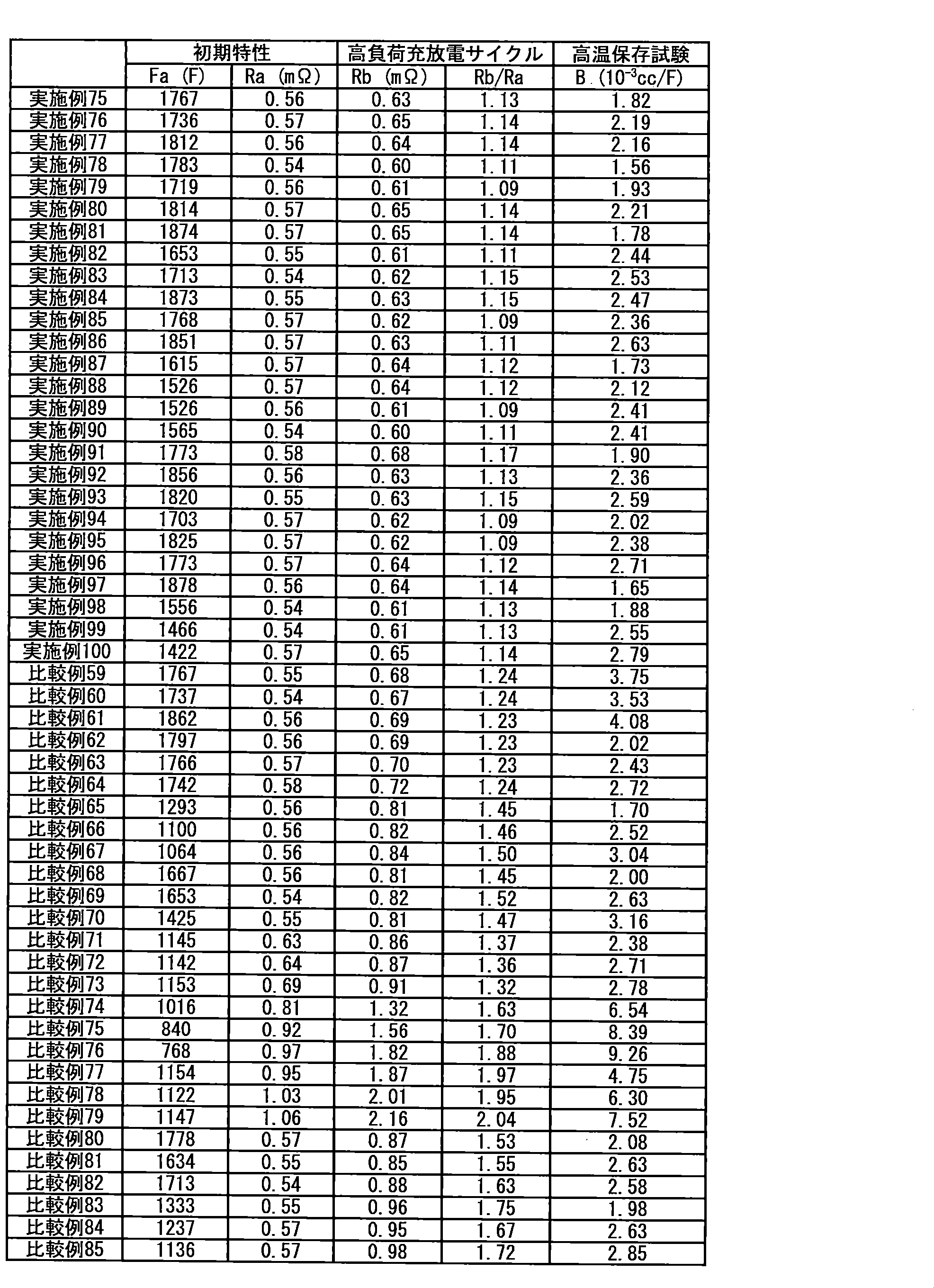
<正極前駆体の製造>
活性炭1fを用いたこと以外は実施例75と同様の方法で正極前駆体17(片面)及び正極前駆体17(両面)を作製した。このとき、正極活物質層の上面の膜厚は55μm、正極活物質層の下面の膜厚は58μmであり、上面を正極前駆体Cy2面、下面を正極前駆体Cx2面とした。 <Example 101>
<Production of positive electrode precursor>
A positive electrode precursor 17 (one side) and a positive electrode precursor 17 (both sides) were produced in the same manner as in Example 75 except that activated carbon 1f was used. At this time, the film thickness of the upper surface of the positive electrode active material layer was 55 μm, the film thickness of the lower surface of the positive electrode active material layer was 58 μm, the upper surface was the positive electrode precursor Cy2 surface, and the lower surface was the positive electrode precursor Cx2 surface.
市販のヤシ殻活性炭のBET比表面積及び細孔分布を、ユアサアイオニクス社製細孔分布測定装置(AUTOSORB-1 AS-1-MP)を用いて、上述した方法によって測定した。その結果、BET比表面積は1,790m2/g、メソ孔量(V1)は0.199cc/g、マイクロ孔量(V2)は0.698cc/g、V1/V2=0.29、そして平均細孔径は20.1Åであった。
このヤシ殻活性炭300gをステンレススチールメッシュ製の籠に入れ、石炭系ピッチ(軟化点:50℃)540gを入れたステンレス製バットの上に置き、両者を電気炉(炉内有効寸法300mm×300mm×300mm)内に設置した。これを窒素雰囲気下、600℃まで8時間で昇温し、同温度で4時間保持することにより熱反応させ、複合多孔質炭素材料1a4を得た。得られた複合多孔質炭素材料1a4を自然冷却により60℃まで冷却した後、電気炉から取り出した。
得られた複合多孔質炭素材料1a4について、上記と同様の方法でBET比表面積及び細孔分布を測定した。その結果、BET比表面積は262m2/g、メソ孔量(Vm1)は0.186cc/g、マイクロ孔量(Vm2)は0.082cc/g、Vm1/Vm2=2.27であった。また、複合多孔質炭素材料1a4において、石炭系ピッチ由来の炭素質材料の活性炭に対する質量比率は78%であった。 <Preparation of Negative Electrode Active Material Preparation Example 1a 4 >
The BET specific surface area and pore distribution of commercially available coconut shell activated carbon were measured by the above-described method using a pore distribution measuring device (AUTOSORB-1 AS-1-MP) manufactured by Yuasa Ionics. As a result, the BET specific surface area was 1,790 m 2 / g, the mesopore volume (V 1 ) was 0.199 cc / g, the micropore volume (V 2 ) was 0.698 cc / g, and V 1 / V 2 = 0. 29, and the average pore diameter was 20.1 mm.
300 g of this coconut shell activated carbon is put in a stainless steel mesh basket, placed on a stainless steel bat containing 540 g of a coal-based pitch (softening point: 50 ° C.), and both are placed in an electric furnace (effective size in the furnace 300 mm × 300 mm × 300 mm). An atmosphere of nitrogen, was heated in 8 hours to 600 ° C., allowed to thermally react by maintaining at the same temperature for 4 hours, to obtain a composite porous carbon material 1a 4. The obtained composite porous carbon material 1a 4 was cooled to 60 ° C. by natural cooling, and then taken out from the electric furnace.
For composite porous carbon material 1a 4 obtained was measured BET specific surface area and pore distribution in the same manner as described above. As a result, the BET specific surface area was 262 m 2 / g, the mesopore volume (V m1 ) was 0.186 cc / g, the micropore volume (V m2 ) was 0.082 cc / g, and V m1 / V m2 = 2.27. there were. Further, in the composite porous carbon material 1a 4, the mass ratio of activated carbon of the carbonaceous material derived from a coal-based pitch was 78%.
複合多孔質炭素材料1a4を用いたこと以外は実施例75と同様の方法で負極13を作製した。このとき、負極活物質層の上面の膜厚は33μm、負極活物質層の下面は30μmであり、上面を負極Ay2面、下面を負極Ax2面とした。 <Manufacture of negative electrode>
A
得られた負極13を1.4cm×2.0cm(2.8cm2)の大きさに1枚切り出し、銅箔に塗工されたAy2面の負極活物質層をスパチュラ、ブラシ、刷毛を用いて除去して作用極とした。対極及び参照極としてそれぞれ金属リチウムを用い、電解液としてエチレンカーボネート(EC)とエチルメチルカーボネート(EMC)の体積比1:1混合溶媒に、LiPF6を1.0mol/Lの濃度で溶解させた非水系溶液を用いて、アルゴンボックス中で電気化学セルを作製した。
得られた電気化学セルについて、東洋システム社製の充放電装置(TOSCAT-3100U)を用いて、以下の手順で初期充電容量を測定した。
電気化学セルに対して、温度25℃において、電流値0.5mA/cm2で電圧値が0.01Vになるまで定電流充電を行った後、更に電流値が0.01mA/cm2になるまで定電圧充電を行った。この定電流充電及び定電圧充電の時の充電容量を初回充電容量として評価したところ、1.6mAhであり、負極13の単位質量当たりの容量(リチウムイオンのドープ量)は1460mAh/gであった。 [Measurement of capacity per unit weight of negative electrode]
Cut one sheet of
With respect to the obtained electrochemical cell, the initial charge capacity was measured by the following procedure using a charge / discharge device (TOSCAT-3100U) manufactured by Toyo System.
Against the electrochemical cell, at a temperature 25 ° C., after the voltage value at a current value 0.5 mA / cm 2 was subjected to constant current charging until 0.01 V, further the current value reached 0.01 mA / cm 2 Until constant voltage charging. When the charging capacity at the time of constant current charging and constant voltage charging was evaluated as the initial charging capacity, it was 1.6 mAh, and the capacity per unit mass of the negative electrode 13 (lithium ion doping amount) was 1460 mAh / g. .
正極前駆体17(片面)、正極前駆体17(両面)、及び負極13を用い、正極前駆体Cx2面と負極Ax2面がセパレータを挟んで対向し、正極前駆体Cy2面と負極Ay2面がセパレータを挟んで対向するように、正極前駆体17(片面)、セパレータ、負極13、セパレータ、正極前駆体17(両面)の順に積層し、電極積層体を作製したこと以外は実施例75と同様の方法で非水系リチウム蓄電素子を作製し、評価した。 <Production and evaluation of non-aqueous lithium storage element>
Using the positive electrode precursor 17 (one side), the positive electrode precursor 17 (both sides), and the
リチウムドープ工程の非水系リチウム蓄電素子の初期充電において、電流値100mAで電圧4.5Vに到達するまで定電流充電を行った後、続けて4.5V定電圧充電を36時間継続することにより、負極にリチウムドープを行ったこと以外は実施例101と同様の方法で非水系リチウム蓄電素子を作製した。 <Example 102>
In the initial charging of the non-aqueous lithium storage element in the lithium doping process, by performing constant current charging until reaching a voltage of 4.5 V at a current value of 100 mA, then continuing 4.5 V constant voltage charging for 36 hours, A non-aqueous lithium storage element was produced in the same manner as in Example 101 except that the negative electrode was doped with lithium.
リチウムドープ工程の非水系リチウム蓄電素子の初期充電において、電流値100mAで電圧4.5Vに到達するまで定電流充電を行った後、続けて4.5V定電圧充電を12時間継続することにより、負極にリチウムドープを行ったこと以外は実施例101と同様の方法で非水系リチウム蓄電素子を作製した。 <Example 103>
In the initial charging of the non-aqueous lithium storage element in the lithium doping step, by performing constant current charging until reaching a voltage of 4.5 V at a current value of 100 mA, and subsequently continuing 4.5 V constant voltage charging for 12 hours, A non-aqueous lithium storage element was produced in the same manner as in Example 101 except that the negative electrode was doped with lithium.
炭酸リチウムの代わりに酸化リチウムを用いたこと以外は実施例101と同様の方法で非水系リチウム蓄電素子を作製した。 <Example 104>
A non-aqueous lithium storage element was produced in the same manner as in Example 101 except that lithium oxide was used instead of lithium carbonate.
炭酸リチウムの代わりに水酸化リチウムを用いたこと以外は実施例101と同様の方法で非水系リチウム蓄電素子を作製した。 <Example 105>
A non-aqueous lithium storage element was produced in the same manner as in Example 101 except that lithium hydroxide was used instead of lithium carbonate.
正極前駆体Cx2面と負極Ay2面がセパレータを挟んで対向し、正極前駆体Cy1面と負極Ax1面がセパレータを挟んで対向するように電極積層体を作製したこと以外は実施例101と同様の方法で非水系リチウム蓄電素子を作製した。 <Comparative Example 86>
Example except that the electrode laminate was prepared such that the positive electrode precursor C x2 surface and the negative electrode A y2 surface were opposed to each other with a separator interposed therebetween, and the positive electrode precursor C y1 surface and the negative electrode A x1 surface were opposed to each other with a separator interposed therebetween. A non-aqueous lithium storage element was produced in the same manner as in 101.
リチウムドープ工程の非水系リチウム蓄電素子の初期充電において、電流値100mAで電圧4.5Vに到達するまで定電流充電を行った後、続けて4.5V定電圧充電を36時間継続することにより、負極にリチウムドープを行ったこと以外は比較例86と同様の方法で非水系リチウム蓄電素子を作製した。 <Comparative Example 87>
In the initial charging of the non-aqueous lithium storage element in the lithium doping process, by performing constant current charging until reaching a voltage of 4.5 V at a current value of 100 mA, then continuing 4.5 V constant voltage charging for 36 hours, A non-aqueous lithium storage element was produced in the same manner as in Comparative Example 86 except that the negative electrode was doped with lithium.
リチウムドープ工程の非水系リチウム蓄電素子の初期充電において、電流値100mAで電圧4.5Vに到達するまで定電流充電を行った後、続けて4.5V定電圧充電を12時間継続することにより、負極にリチウムドープを行ったこと以外は比較例86と同様の方法で非水系リチウム蓄電素子を作製した。 <Comparative Example 88>
In the initial charging of the non-aqueous lithium storage element in the lithium doping step, by performing constant current charging until reaching a voltage of 4.5 V at a current value of 100 mA, and subsequently continuing 4.5 V constant voltage charging for 12 hours, A non-aqueous lithium storage element was produced in the same manner as in Comparative Example 86 except that the negative electrode was doped with lithium.
炭酸リチウムの代わりに酸化リチウムを用いたこと以外は比較例86と同様の方法で非水系リチウム蓄電素子を作製した。 <Comparative Example 89>
A non-aqueous lithium storage element was produced in the same manner as in Comparative Example 86 except that lithium oxide was used instead of lithium carbonate.
炭酸リチウムの代わりに水酸化リチウムを用いたこと以外は比較例86と同様の方法で非水系リチウム蓄電素子を作製した。 <Comparative Example 90>
A non-aqueous lithium electricity storage device was produced in the same manner as in Comparative Example 86 except that lithium hydroxide was used instead of lithium carbonate.
正極前駆体11(両面)を12.0cm×210.0cmの大きさに切断し(正極活物質層の大きさが10.0cm×210.0cm、正極集電体上に正極活物質層が塗工されていない正極未塗工部が2.0cm×210.0cmである。)、負極8を12.1×220.0cmの大きさに切断し(負極活物質層の大きさが10.1cm×220.0cm、負極集電体上に負極活物質層が塗工されていない負極未塗工部が2.0cm×220.0cmである。)、切り出された正極前駆体及び負極をポリエチレン製のセパレータ(旭化成株式会社製、厚み10μm)を介して捲回し、電極積層体を作製した。このとき、正極前駆体Cx1面と負極Ax1面がセパレータを挟んで対向し、正極前駆体Cy1面と負極Ay1面がセパレータを挟んで対向するようにして楕円形状に捲回した。得られた電極積層体に正極端子及び負極端子を超音波溶接し、アルミラミネート包材で形成された容器に入れ、電極端子部を含む3辺をヒートシールによりシールした。その後、実施例75と同様の方法で非水系リチウム蓄電素子を作製し、評価した。 <Example 106>
The positive electrode precursor 11 (both sides) is cut into a size of 12.0 cm × 210.0 cm (the size of the positive electrode active material layer is 10.0 cm × 210.0 cm, and the positive electrode active material layer is applied on the positive electrode current collector). The uncoated positive electrode uncoated portion is 2.0 cm × 210.0 cm), and the
正極前駆体17(両面)を12.0cm×210.0cmの大きさに切断し(正極活物質層の大きさが10.0cm×210.0cm、正極集電体上に正極活物質層が塗工されていない正極未塗工部が2.0cm×210.0cmである。)、負極13を12.1×220.0cmの大きさに切断し(負極活物質層の大きさが10.1cm×220.0cm、負極集電体上に負極活物質層が塗工されていない負極未塗工部が2.0cm×220.0cmである。)、切り出された正極前駆体及び負極をポリエチレン製のセパレータ(旭化成株式会社製、厚み10μm)を介して捲回し、電極積層体を作製した。このとき、正極前駆体Cx2面と負極Ax2面がセパレータを挟んで対向し、正極前駆体Cy2面と負極Ay2面がセパレータを挟んで対向するようにして楕円形状に捲回した。得られた電極積層体に正極端子及び負極端子を超音波溶接し、アルミラミネート包材で形成された容器に入れ、電極端子部を含む3辺をヒートシールによりシールした。その後、実施例75と同様の方法で非水系リチウム蓄電素子を作製し、評価した。 <Example 107>
The positive electrode precursor 17 (both sides) is cut into a size of 12.0 cm × 210.0 cm (the size of the positive electrode active material layer is 10.0 cm × 210.0 cm, and the positive electrode active material layer is applied on the positive electrode current collector). The uncoated positive electrode uncoated portion is 2.0 cm × 210.0 cm.), And the
正極前駆体Cx1面と負極Ay1面がセパレータを挟んで対向し、正極前駆体Cy1面と負極Ax1面がセパレータを挟んで対向するようにして楕円形状に捲回したこと以外は実施例106と同様の方法で非水系リチウム蓄電素子を作製した。 <Comparative Example 91>
Implementation was performed except that the positive electrode precursor C x1 surface and the negative electrode A y1 surface were opposed to each other with a separator interposed therebetween, and the positive electrode precursor C y1 surface and the negative electrode A x1 surface were opposed to each other with a separator interposed therebetween. A non-aqueous lithium electricity storage device was produced in the same manner as in Example 106.
正極前駆体Cx2面と負極Ay2面がセパレータを挟んで対向し、正極前駆体Cy2面と負極Ax2面がセパレータを挟んで対向するようにして楕円形状に捲回したこと以外は実施例107と同様の方法で非水系リチウム蓄電素子を作製した。 <Comparative Example 92>
Except that the positive electrode precursor C x2 surface and the negative electrode A y2 surface are opposed to each other with a separator interposed therebetween, and the positive electrode precursor C y2 surface and the negative electrode A x2 surface are opposed to each other with a separator interposed therebetween. A non-aqueous lithium electricity storage device was produced in the same manner as in Example 107.

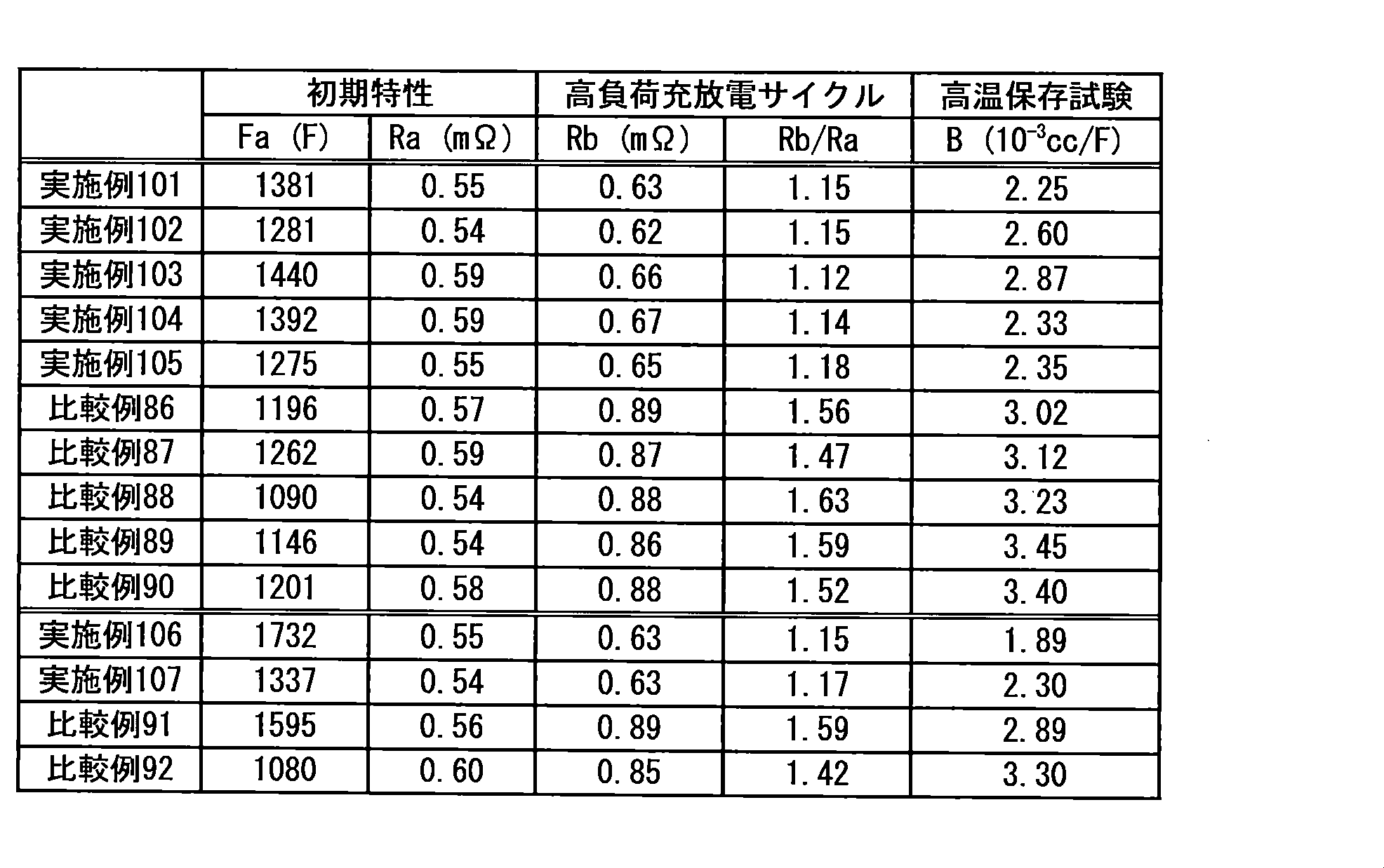
また、式(1)~(3)で表される化合物が正極表面に存在することで、正極中のリチウム化合物と非水系電解液の反応を抑制することができ、高温保存試験におけるガス発生を抑制できたと考えられる。 From the evaluation results shown in Tables 7 to 10, C x1 / C y1 is 1.02 or more and 1.35 or less, which is the range of the constituent requirements of the present invention, and A x1 / A y1 is 0.74 or more and 0.00. When it is 98 or less, uneven distribution of ions in the non-aqueous electrolyte in a high-load charge / discharge cycle can be suppressed, and decomposition of the lithium compound on the Cy plane having a large potential fluctuation can be suppressed. It is thought that the increase in resistance could be suppressed.
In addition, the presence of the compounds represented by the formulas (1) to (3) on the surface of the positive electrode can suppress the reaction between the lithium compound in the positive electrode and the non-aqueous electrolyte, and can prevent gas generation in a high-temperature storage test. It is thought that it was able to be suppressed.
本発明の非水系リチウム蓄電素子は、リチウムイオンキャパシタ又はリチウムイオン二次電池として適用したときに、本発明の効果が最大限に発揮されるため、好ましい。 The non-aqueous lithium storage element of the present invention can be made by connecting a plurality of non-aqueous lithium storage elements in series or in parallel. The non-aqueous lithium power storage device and the power storage module of the present invention include a power regeneration system for a hybrid drive system of an automobile that requires high load charge / discharge cycle characteristics, a power load in a natural power generation such as solar power generation and wind power generation, a microgrid, etc. Leveling system, uninterruptible power supply system in factory production facilities, etc., non-contact power supply system for leveling voltage fluctuations and energy storage such as microwave transmission and electrolytic resonance, use of power generated by vibration power generation, etc. It can be suitably used for an energy harvesting system for the purpose.
The non-aqueous lithium electricity storage device of the present invention is preferable because the effects of the present invention are exhibited to the maximum when applied as a lithium ion capacitor or a lithium ion secondary battery.
2 負極集電体
3 負極集電体の第1面
4 負極集電体の第2面
5 第1負極活物質層
6 第2負極活物質層
7 正極活物質層Cx面
8 正極活物質層Cy面
9 無孔状の正極集電体
10 負極活物質層Ax面
11 負極活物質層Ay面
12 無孔状の負極集電体
13 セパレータ
14 電極積層体
15 外装体 DESCRIPTION OF SYMBOLS 1
Claims (34)
- 活物質以外のリチウム化合物を含む正極、負極、セパレータ、リチウムイオンを含む非水系電解液からなる非水系リチウム蓄電素子であって、前記リチウム化合物の平均粒子径をX1とするとき、0.1μm≦X1≦10.0μmであり、正極活物質の平均粒子径をY1とするとき、2.0μm≦Y1≦20.0μmであり、X1<Y1であり、前記正極中に含まれる前記リチウム化合物の量が1質量%以上50質量%以下である非水系リチウム蓄電素子。 The positive electrode containing a lithium compound other than the active material, a negative electrode, a separator, a nonaqueous lithium battery elements consisting of a non-aqueous electrolyte containing lithium ions, an average particle diameter of the lithium compound when the X 1, 0.1 [mu] m ≦ X 1 ≦ 10.0 μm, and when the average particle diameter of the positive electrode active material is Y 1 , 2.0 μm ≦ Y 1 ≦ 20.0 μm, X 1 <Y 1 , and included in the positive electrode The non-aqueous lithium electrical storage element whose quantity of the said lithium compound is 1 to 50 mass%.
- 前記正極表面のSEM-EDXにより得られる元素マッピングにおいて、輝度値の平均値を基準に二値化した酸素マッピングに対するフッ素マッピングの面積重複率A1が、40%以上99%以下である、請求項1に記載の非水系リチウム蓄電素子。 Wherein the elemental mapping obtained by SEM-EDX of the positive electrode surface, average fluorine area overlap rate A 1 mapping to oxygen mapping binarized on the basis of the luminance values is 99% or less 40%, claim The non-aqueous lithium storage element according to 1.
- BIB加工した正極断面のSEM-EDXにより得られる元素マッピングにおいて、輝度値の平均値を基準に二値化した酸素マッピングに対するフッ素マッピングの面積重複率A2が10%以上60%以下である、請求項1又は2に記載の非水系リチウム蓄電素子。 In the element mapping obtained by SEM-EDX of the BIB processed positive electrode section, is 60% or less an area overlapping ratio A 2 fluorine mapping at least 10% of oxygen mapping binarized on the basis of the average value of the brightness value, wherein Item 3. The nonaqueous lithium storage element according to Item 1 or 2.
- 前記X1が0.5μm以上5.0μm以下である、請求項1~3のいずれか1項に記載の非水系リチウム蓄電素子。 Wherein X 1 is 0.5μm or more 5.0μm or less, a non-aqueous lithium storage element according to any one of claims 1 to 3.
- 前記正極中に含まれるリチウム化合物の量が2質量%以上20質量%以下である、請求項1~4のいずれか1項に記載の非水系リチウム蓄電素子。 The non-aqueous lithium storage element according to any one of claims 1 to 4, wherein the amount of the lithium compound contained in the positive electrode is 2% by mass or more and 20% by mass or less.
- 前記負極は、無孔状の負極集電体と、前記負極集電体の片面又は両面上に設けられた、負極活物質を含む負極活物質層とを有し、
前記負極活物質は、リチウムイオンを吸蔵及び放出可能な炭素材料を含み、
前記正極の少なくとも1つは、無孔状の正極集電体と、前記正極集電体の両面上に設けられた、正極活物質を含む正極活物質層とを有し、
前記正極の一方の面(Cy面)の正極活物質層の目付をCy1(g/m2)とし、他方の面(Cx面)の正極活物質層の目付をCx1(g/m2)とするとき、Cy1/Cx1は0.70以上0.98以下であり、
Cy面の単位面積当たりのリチウム化合物量をCy2(g/m2)とし、Cx面の単位面積当たりのリチウム化合物量をCx2(g/m2)とするとき、Cy2及びCx2は0.10以上20.0以下であり、Cy2/Cx2は0.10以上1.0以下である、請求項1~5のいずれか1項に記載の非水系リチウム蓄電素子。 The negative electrode has a non-porous negative electrode current collector and a negative electrode active material layer including a negative electrode active material provided on one or both surfaces of the negative electrode current collector,
The negative electrode active material includes a carbon material capable of occluding and releasing lithium ions,
At least one of the positive electrodes has a non-porous positive electrode current collector, and a positive electrode active material layer including a positive electrode active material provided on both surfaces of the positive electrode current collector,
Wherein the basis weight of the positive electrode active material layer on one surface of the positive electrode (C y plane) and C y1 (g / m 2) , the other side of the basis weight of the positive electrode active material layer (C x plane) C x1 (g / m 2 ), C y1 / C x1 is 0.70 or more and 0.98 or less,
When the amount of lithium compound per unit area on the Cy plane is C y2 (g / m 2 ) and the amount of lithium compound per unit area on the C x plane is C x2 (g / m 2 ), C y2 and C 6. The non-aqueous lithium storage element according to claim 1, wherein x2 is 0.10 or more and 20.0 or less, and C y2 / C x2 is 0.10 or more and 1.0 or less. - 前記正極は、正極集電体と、前記正極集電体の片面又は両面上に設けられた、前記正極活物質を含む正極活物質層とを有し、
前記負極は、貫通孔を持たない負極集電体と、前記負極集電体の両面上に設けられた、負極活物質を含む第1及び第2負極活物質層とを有し、
前記第1及び第2負極活物質層は、それぞれリチウムイオンを吸蔵しており、
前記負極集電体の第1面上に設けられた前記第1負極活物質層の固体7Li-NMRスペクトルについて、-20ppm~60ppmのピーク面積より計算される、前記リチウムイオンを吸蔵した前記第1負極活物質層の単位質量当たりのリチウム量をq1とし、かつ、前記第1面の裏面である前記負極集電体の第2面上に設けられた前記第2負極活物質層の固体7Li-NMRスペクトルについて、-20ppm~60ppmのピーク面積より計算される、前記リチウムイオンを吸蔵した前記第2負極活物質層の単位質量当たりのリチウム量をq2としたとき、q1とq2の変動係数CVが、0.001以上0.500以下である、請求項1~6のいずれか1項に記載の非水系リチウム蓄電素子。 The positive electrode includes a positive electrode current collector, and a positive electrode active material layer including the positive electrode active material provided on one or both surfaces of the positive electrode current collector,
The negative electrode has a negative electrode current collector having no through holes, and first and second negative electrode active material layers including a negative electrode active material provided on both surfaces of the negative electrode current collector,
Each of the first and second negative electrode active material layers occludes lithium ions,
The solid 7 Li-NMR spectrum of the first negative electrode active material layer provided on the first surface of the negative electrode current collector is calculated from the peak area of −20 ppm to 60 ppm, and the first that absorbs the lithium ions. the amount of lithium per unit mass of 1 negative electrode active material layer and q 1, and the a rear surface of the first surface wherein the anode current collector and the second anode active material layer provided on the second surface of the solid 7 For the Li-NMR spectrum, when q 2 represents the amount of lithium per unit mass of the second negative electrode active material layer occluded with lithium ions calculated from the peak area of −20 ppm to 60 ppm, q 1 and q 7. The non-aqueous lithium storage element according to claim 1, wherein a variation coefficient CV of 2 is 0.001 or more and 0.500 or less. - 前記正極活物質層の固体7Li-NMRスペクトルについて、繰り返し待ち時間10秒とした測定により得られた-40ppm~40ppmのスペクトル範囲におけるピーク面積をaとし、繰り返し待ち時間3,000秒とした測定により得られた-40ppm~40ppmのスペクトル範囲におけるピーク面積をbとしたとき、1.04≦b/a≦5.56である、請求項7に記載の非水系リチウム蓄電素子。 For the solid 7 Li-NMR spectrum of the positive electrode active material layer, the peak area in the spectrum range of −40 ppm to 40 ppm obtained by measurement with a repetition waiting time of 10 seconds is a, and the repetition waiting time is 3,000 seconds. The nonaqueous lithium storage element according to claim 7, wherein 1.04 ≦ b / a ≦ 5.56, where b is a peak area in a spectrum range of −40 ppm to 40 ppm obtained by the above.
- 前記第1又は第2負極活物質層の単位体積当たりのBET比表面積が、20m2/cc以上1,500m2/cc以下である、請求項7又は8に記載の非水系リチウム蓄電素子。 The non-aqueous lithium storage element according to claim 7 or 8, wherein a BET specific surface area per unit volume of the first or second negative electrode active material layer is 20 m 2 / cc or more and 1,500 m 2 / cc or less.
- 前記第1又は第2負極活物質層の単位体積当たりのBET比表面積が、1m2/cc以上50m2/cc以下である、請求項7又は8に記載の非水系リチウム蓄電素子。 The non-aqueous lithium storage element according to claim 7 or 8, wherein a BET specific surface area per unit volume of the first or second negative electrode active material layer is 1 m 2 / cc or more and 50 m 2 / cc or less.
- 前記正極活物質は、BJH法により算出した直径20Å以上500Å以下の細孔に由来するメソ孔量をV1(cc/g)、MP法により算出した直径20Å未満の細孔に由来するマイクロ孔量をV2(cc/g)とするとき、0.3<V1≦0.8、及び0.5≦V2≦1.0を満たし、かつ、BET法により測定される比表面積が1,500m2/g以上3,000m2/g以下を示す活性炭である、請求項1~10のいずれか1項に記載の非水系リチウム蓄電素子。 The positive electrode active material has a mesopore amount derived from pores having a diameter of 20 to 500 mm calculated by the BJH method as V 1 (cc / g), and micropores derived from pores having a diameter of less than 20 mm calculated by the MP method. When the amount is V 2 (cc / g), 0.3 <V 1 ≦ 0.8 and 0.5 ≦ V 2 ≦ 1.0 are satisfied, and the specific surface area measured by the BET method is 1 The nonaqueous lithium storage element according to any one of claims 1 to 10, wherein the nonaqueous lithium storage element is activated carbon exhibiting ≧ 500 m 2 / g and 3,000 m 2 / g.
- 前記正極活物質は、BJH法により算出した直径20Å以上500Å以下の細孔に由来するメソ孔量をV1(cc/g)、MP法により算出した直径20Å未満の細孔に由来するマイクロ孔量をV2(cc/g)とするとき、0.8<V1≦2.5、及び0.8<V2≦3.0を満たし、かつ、BET法により測定される比表面積が2,300m2/g以上4,000m2/g以下を示す活性炭である、請求項1~10のいずれか1項に記載の非水系リチウム蓄電素子。 The positive electrode active material has a mesopore amount derived from pores having a diameter of 20 to 500 mm calculated by the BJH method as V 1 (cc / g), and micropores derived from pores having a diameter of less than 20 mm calculated by the MP method. When the amount is V 2 (cc / g), 0.8 <V 1 ≦ 2.5 and 0.8 <V 2 ≦ 3.0 are satisfied, and the specific surface area measured by the BET method is 2 The non-aqueous lithium storage element according to any one of claims 1 to 10, wherein the non-aqueous lithium storage element is activated carbon exhibiting ≧ 300 m 2 / g and 4,000 m 2 / g.
- 正極活物質以外のリチウム化合物を含む正極と、
負極と、
セパレータと、
リチウムイオンを含む非水系電解液と、
を有する非水系リチウム蓄電素子であって、
前記正極は、正極集電体と、前記正極集電体の片面又は両面上に設けられた、正極活物質を含む正極活物質層とを有し、
前記負極は、貫通孔を持たない負極集電体と、前記負極集電体の両面上に設けられた、負極活物質を含む第1及び第2負極活物質層とを有し、
前記第1及び第2負極活物質層は、それぞれリチウムイオンを吸蔵しており、
前記負極集電体の第1面上に設けられた前記第1負極活物質層の固体7Li-NMRスペクトルについて、-20ppm~60ppmのピーク面積より計算される、前記リチウムイオンを吸蔵した前記第1負極活物質層の単位質量当たりのリチウム量をq1とし、前記第1面の裏面である前記負極集電体の第2面上に設けられた前記第2負極活物質層の固体7Li-NMRスペクトルについて、-20ppm~60ppmのピーク面積より計算される、前記リチウムイオンを吸蔵した第2負極活物質層の単位質量当たりのリチウム量をq2としたとき、q1とq2の変動係数CVが0.001以上0.50以下であり、かつ、前記非水系リチウム蓄電素子に対して、環境温度25℃、セル電圧2.2V~3.8V、300Cのレートで充放電サイクルを60,000回行ったときに、前記60,000回の充放電サイクル後の内部抵抗をRb(Ω)、かつ、前記充放電サイクルを開始する前の内部抵抗をRa(Ω)としたとき、Rb/Raが0.9以上2.0以下である前記非水系リチウム蓄電素子。 A positive electrode containing a lithium compound other than the positive electrode active material;
A negative electrode,
A separator;
A non-aqueous electrolyte containing lithium ions;
A non-aqueous lithium electricity storage device having
The positive electrode has a positive electrode current collector, and a positive electrode active material layer including a positive electrode active material provided on one or both surfaces of the positive electrode current collector,
The negative electrode has a negative electrode current collector having no through holes, and first and second negative electrode active material layers including a negative electrode active material provided on both surfaces of the negative electrode current collector,
Each of the first and second negative electrode active material layers occludes lithium ions,
The solid 7 Li-NMR spectrum of the first negative electrode active material layer provided on the first surface of the negative electrode current collector is calculated from the peak area of −20 ppm to 60 ppm, and the first that absorbs the lithium ions. the amount of lithium per unit mass of 1 negative electrode active material layer and q 1, the first surface wherein a back surface of said provided second surface of the negative electrode current collector second anode active solid material layer 7 Li for -NMR spectra are calculated from the peak area of -20 ppm ~ 60 ppm, when the amount of lithium per unit mass of the second anode active material layer which occludes lithium ions was q 2, variation of q 1 and q 2 The coefficient CV is 0.001 or more and 0.50 or less, and the nonaqueous lithium storage element is charged at an environmental temperature of 25 ° C., a cell voltage of 2.2 V to 3.8 V, and a rate of 300 C. When the electric cycle is performed 60,000 times, the internal resistance after the 60,000 charge / discharge cycles is Rb (Ω), and the internal resistance before starting the charge / discharge cycle is Ra (Ω). The non-aqueous lithium electricity storage element, wherein Rb / Ra is 0.9 or more and 2.0 or less. - 前記正極の無孔状の正極集電体の両面に前記活物質が塗布されており、
前記負極の無孔状の負極集電体の両面に、リチウムイオンを吸蔵及び放出可能な負極活物質が塗布されており、
前記正極の一方の面(Cx面)の正極活物質層の目付をCx1(g/m2)とし、もう片方の面(Cy面)の正極活物質層の目付をCy1(g/m2)とするとき、Cx1/Cy1が1.02以上1.35以下であり、
前記Cy面と対向する前記負極の一方の面(Ay面)の負極活物質層の目付をAy1(g/m2)とし、もう片方の面(Ax面)の負極活物質層の目付をAx1(g/m2)とするとき、Ax1/Ay1が0.74以上0.98以下であり、かつ、
前記Cx面の前記リチウム化合物の目付をCx2(g/m2)とし、前記Cy面の前記リチウム化合物の目付をCy2(g/m2)とするとき、Cx2及びCy2は、それぞれ0.10以上20.0以下であり、かつCy2/Cx2が0.10以上0.95以下である、請求項1~12のいずれか1項に記載の非水系リチウム蓄電素子。 The active material is applied to both surfaces of the non-porous positive electrode current collector of the positive electrode,
A negative electrode active material capable of inserting and extracting lithium ions is applied to both surfaces of the non-porous negative electrode current collector of the negative electrode,
The basis weight of the positive electrode active material layer on one surface (C x surface) of the positive electrode is C x1 (g / m 2 ), and the basis weight of the positive electrode active material layer on the other surface (C y surface) is C y1 (g / M 2 ), C x1 / C y1 is 1.02 or more and 1.35 or less,
Anode active basis weight material layer and A y1 (g / m 2) , the negative electrode active material layer of the other surface (A x plane) of the one surface of the negative electrode facing the C y plane (A y plane) When the basis weight of A x1 (g / m 2 ) is A x1 / A y1 is 0.74 or more and 0.98 or less, and
The basis weight of the lithium compound of said C x plane and C x2 (g / m 2) , when the basis weight of said lithium compound of said C y plane and C y2 (g / m 2) , C x2 and C y2 is The nonaqueous lithium storage element according to any one of claims 1 to 12, wherein each is 0.10 or more and 20.0 or less and C y2 / C x2 is 0.10 or more and 0.95 or less. - (Cx1+Cx2)Ax1/(Cy1+Cy2)Ay1が0.80以上1.32以下である、請求項14に記載の非水系リチウム蓄電素子。 The non-aqueous lithium storage element according to claim 14, wherein (C x1 + C x2 ) A x1 / (C y1 + C y2 ) A y1 is 0.80 or more and 1.32 or less.
- 前記Cx面と前記Ax面が対向する、請求項14又は15に記載の非水系リチウム蓄電素子。 Wherein C x plane and the A x plane faces, non-aqueous lithium storage element according to claim 14 or 15.
- 前記Cy面が、下記式(1)~(3):


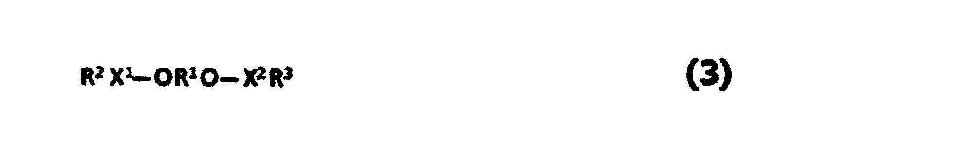
で表される1種以上の化合物を含み、かつ、
前記Cy面の単位質量当たりの前記式(1)~(3)で表される化合物の含有量をCy3(mol/g)とするとき、Cy3が1.60×10-4以上300×10-4以下である、請求項14~16のいずれか1項に記載の非水系リチウム蓄電素子。 The Cy plane is represented by the following formulas (1) to (3):
Including one or more compounds represented by:
When the content of the compound represented by the formulas (1) to (3) per unit mass on the Cy plane is C y3 (mol / g), C y3 is 1.60 × 10 −4 or more and 300 The non-aqueous lithium electricity storage device according to any one of claims 14 to 16, which is × 10 -4 or less. - 前記Ay面に含有される前記式(1)~(3)で表される化合物の含有量をAy3(mol/g)とするとき、Cy3/Ay3が0.2以上20以下である、請求項17に記載の非水系リチウム蓄電素子。 When the content of the compound represented by the formulas (1) to (3) contained in the Ay plane is Ay3 (mol / g), Cy3 / Ay3 is 0.2 or more and 20 or less. The non-aqueous lithium storage element according to claim 17, wherein
- 前記リチウム化合物が、炭酸リチウム、酸化リチウム、又は水酸化リチウムである、請求項1~12、14~18のいずれか1項に記載の非水系リチウム蓄電素子。 The nonaqueous lithium storage element according to any one of claims 1 to 12, and 14 to 18, wherein the lithium compound is lithium carbonate, lithium oxide, or lithium hydroxide.
- 前記リチウム化合物が炭酸リチウムであり、かつ、
前記Cx面及びCy面の顕微ラマン分光測定により得られるイメージング画像において、炭酸イオンマッピングの面積割合をSx%及びSy%とするとき、Sx及びSyは、それぞれ1以上40以下であり、かつSx/Syが1.00以上2.00以下である、
請求項14~19のいずれか1項に記載の非水系リチウム蓄電素子。 The lithium compound is lithium carbonate, and
In the C x plane and C y plane Raman spectroscopic imaging image obtained by measurement of, when the area ratio of carbonate ion mapping S x% and S y%, S x and S y are each 1 or more and 40 or less , and the and S x / S y is 1.00 to 2.00,
The non-aqueous lithium storage element according to any one of claims 14 to 19. - 前記Cx面又はCy面を有する正極活物質層に含まれる正極活物質が、BJH法により算出した直径20Å以上500Å以下の細孔に由来するメソ孔量をV1(cc/g)、MP法により算出した直径20Å未満の細孔に由来するマイクロ孔量をV2(cc/g)とするとき、0.3<V1≦0.8、及び0.5≦V2≦1.0を満たし、かつ、BET法により測定される比表面積が1,500m2/g以上3,000m2/g以下を示す活性炭である、請求項14~20のいずれか1項に記載の非水系リチウム蓄電素子。 The positive electrode active material contained in the positive electrode active material layer having the C x plane or the Cy plane has a mesopore amount derived from pores having a diameter of 20 mm or more and 500 mm or less calculated by the BJH method as V 1 (cc / g), When the amount of micropores derived from pores having a diameter of less than 20 mm calculated by the MP method is V 2 (cc / g), 0.3 <V 1 ≦ 0.8 and 0.5 ≦ V 2 ≦ 1. The non-aqueous system according to any one of claims 14 to 20, which is activated carbon that satisfies 0 and has a specific surface area measured by the BET method of 1,500 m 2 / g to 3,000 m 2 / g. Lithium storage element.
- 前記Cx面又はCy面を有する正極活物質層に含まれる正極活物質が、BJH法により算出した直径20Å以上500Å以下の細孔に由来するメソ孔量V1(cc/g)が0.8<V1≦2.5を満たし、MP法により算出した直径20Å未満の細孔に由来するマイクロ孔量V2(cc/g)が0.8<V2≦3.0を満たし、かつ、BET法により測定される比表面積が2,300m2/g以上4,000m2/g以下を示す活性炭である、請求項14~20のいずれか1項に記載の非水系リチウム蓄電素子。 The positive electrode active material contained in the positive electrode active material layer having a C x plane or C y plane, meso Anaryou V 1 (cc / g) derived from the pores below the calculated diameter 20Å or 500Å where the BJH method 0 .8 <V 1 ≦ 2.5, the micropore amount V 2 (cc / g) derived from the pores having a diameter of less than 20 mm calculated by the MP method satisfies 0.8 <V 2 ≦ 3.0, The non-aqueous lithium storage element according to any one of claims 14 to 20, which is activated carbon having a specific surface area measured by a BET method of 2,300 m 2 / g to 4,000 m 2 / g.
- 前記負極活物質に対する前記リチウムイオンのドープ量が、前記負極活物質の単位質量当たり530mAh/g以上2,500mAh/g以下である、請求項1~12、14~22のいずれか1項に記載の非水系リチウム蓄電素子。 The doping amount of the lithium ion with respect to the negative electrode active material is 530 mAh / g or more and 2,500 mAh / g or less per unit mass of the negative electrode active material, according to any one of claims 1 to 12 and 14 to 22. Non-aqueous lithium storage element.
- 前記負極活物質のBET比表面積が100m2/g以上1,500m2/g以下である、請求項23に記載の非水系リチウム蓄電素子。 The non-aqueous lithium storage element according to claim 23, wherein the negative electrode active material has a BET specific surface area of 100 m 2 / g or more and 1,500 m 2 / g or less.
- 前記負極活物質に対する前記リチウムイオンのドープ量が、該負極活物質の単位質量当たり50mAh/g以上700mAh/g以下である、請求項1~12、14~22のいずれか1項に記載の非水系リチウム蓄電素子。 The non-conducting material according to any one of claims 1 to 12, and 14 to 22, wherein a doping amount of the lithium ions with respect to the negative electrode active material is 50 mAh / g or more and 700 mAh / g or less per unit mass of the negative electrode active material. Water-based lithium storage element.
- 前記負極活物質のBET比表面積が1m2/g以上50m2/g以下である、請求項25に記載の非水系リチウム蓄電素子。 The non-aqueous lithium storage element according to claim 25, wherein the negative electrode active material has a BET specific surface area of 1 m 2 / g or more and 50 m 2 / g or less.
- 前記負極活物質の平均粒子径が1μm以上10μm以下である、請求項1~22、25、26のいずれか1項に記載の非水系リチウム蓄電素子。 The non-aqueous lithium storage element according to any one of claims 1 to 22, 25, and 26, wherein an average particle size of the negative electrode active material is 1 μm or more and 10 μm or less.
- 請求項1~27の非水系リチウム蓄電素子を含む蓄電モジュール。 An electricity storage module including the non-aqueous lithium electricity storage element according to claims 1 to 27.
- 請求項1~27の非水系リチウム蓄電素子又は請求項28の蓄電モジュールを含む電力回生システム。 A power regeneration system including the non-aqueous lithium storage element according to claims 1 to 27 or the storage module according to claim 28.
- 請求項1~27の非水系リチウム蓄電素子又は請求項28の蓄電モジュールを含む電力負荷平準化システム。 A power load leveling system including the non-aqueous lithium storage element according to claims 1 to 27 or the storage module according to claim 28.
- 請求項1~27の非水系リチウム蓄電素子又は請求項28の蓄電モジュールを含む無停電電源システム。 An uninterruptible power supply system including the non-aqueous lithium storage element according to claims 1 to 27 or the storage module according to claim 28.
- 請求項1~27の非水系リチウム蓄電素子又は請求項28の蓄電モジュールを含む非接触給電システム。 A non-contact power supply system including the non-aqueous lithium storage element according to claim 1 or 27 or the storage module according to claim 28.
- 請求項1~27の非水系リチウム蓄電素子又は請求項28の蓄電モジュールを含むエナジーハーベストシステム。 An energy harvesting system including the non-aqueous lithium storage element according to claims 1 to 27 or the storage module according to claim 28.
- 請求項1~27の非水系リチウム蓄電素子又は請求項28の蓄電モジュールを含む蓄電システム。 A power storage system including the non-aqueous lithium power storage element according to claim 1 or 27 or the power storage module according to claim 28.
Priority Applications (9)
| Application Number | Priority Date | Filing Date | Title |
|---|---|---|---|
| EP17741570.0A EP3392893B1 (en) | 2016-01-22 | 2017-01-20 | Nonaqueous lithium storage element |
| JP2017509060A JP6262402B2 (en) | 2016-01-22 | 2017-01-20 | Non-aqueous lithium storage element |
| CN201780007112.1A CN108475585B (en) | 2016-01-22 | 2017-01-20 | Nonaqueous lithium storage element |
| KR1020187020524A KR102049220B1 (en) | 2016-01-22 | 2017-01-20 | Non-aqueous lithium battery |
| EP20179869.1A EP3770933B1 (en) | 2016-01-22 | 2017-01-20 | Nonaqueous lithium storage element |
| US16/069,930 US10395848B2 (en) | 2016-01-22 | 2017-01-20 | Nonaqueous lithium storage element |
| KR1020197034082A KR102333852B1 (en) | 2016-01-22 | 2017-01-20 | Nonaqueous lithium storage element |
| CN202010263870.3A CN111415821B (en) | 2016-01-22 | 2017-01-20 | Method for manufacturing nonaqueous lithium storage device |
| US16/502,499 US10825616B2 (en) | 2016-01-22 | 2019-07-03 | Nonaqueous lithium storage element |
Applications Claiming Priority (10)
| Application Number | Priority Date | Filing Date | Title |
|---|---|---|---|
| JP2016010895 | 2016-01-22 | ||
| JP2016-010895 | 2016-01-22 | ||
| JP2016-155480 | 2016-08-08 | ||
| JP2016155480 | 2016-08-08 | ||
| JP2016155794 | 2016-08-08 | ||
| JP2016-155794 | 2016-08-08 | ||
| JP2016-192448 | 2016-09-30 | ||
| JP2016-192586 | 2016-09-30 | ||
| JP2016192448 | 2016-09-30 | ||
| JP2016192586 | 2016-09-30 |
Related Child Applications (2)
| Application Number | Title | Priority Date | Filing Date |
|---|---|---|---|
| US16/069,930 A-371-Of-International US10395848B2 (en) | 2016-01-22 | 2017-01-20 | Nonaqueous lithium storage element |
| US16/502,499 Continuation US10825616B2 (en) | 2016-01-22 | 2019-07-03 | Nonaqueous lithium storage element |
Publications (1)
| Publication Number | Publication Date |
|---|---|
| WO2017126693A1 true WO2017126693A1 (en) | 2017-07-27 |
Family
ID=59362391
Family Applications (1)
| Application Number | Title | Priority Date | Filing Date |
|---|---|---|---|
| PCT/JP2017/002020 WO2017126693A1 (en) | 2016-01-22 | 2017-01-20 | Nonaqueous lithium storage element |
Country Status (7)
| Country | Link |
|---|---|
| US (2) | US10395848B2 (en) |
| EP (2) | EP3770933B1 (en) |
| JP (2) | JP6262402B2 (en) |
| KR (2) | KR102333852B1 (en) |
| CN (2) | CN111415821B (en) |
| TW (1) | TWI641008B (en) |
| WO (1) | WO2017126693A1 (en) |
Cited By (4)
| Publication number | Priority date | Publication date | Assignee | Title |
|---|---|---|---|---|
| WO2019156090A1 (en) * | 2018-02-07 | 2019-08-15 | 旭化成株式会社 | Non-aqueous lithium electric storage element |
| JP2020140889A (en) * | 2019-02-28 | 2020-09-03 | 旭化成株式会社 | Positive electrode for non-aqueous lithium power storage element |
| JP2020167350A (en) * | 2019-03-29 | 2020-10-08 | 旭化成株式会社 | Method for manufacturing nonaqueous alkali metal power storage element |
| EP3712915A4 (en) * | 2017-11-14 | 2021-02-17 | Asahi Kasei Kabushiki Kaisha | Non-aqueous lithium-type electricity storage element |
Families Citing this family (2)
| Publication number | Priority date | Publication date | Assignee | Title |
|---|---|---|---|---|
| US10646813B2 (en) * | 2016-09-23 | 2020-05-12 | Lehigh University | Gas separation apparatus and methods using same |
| KR102576896B1 (en) * | 2019-03-29 | 2023-09-11 | 아사히 가세이 가부시키가이샤 | Method for manufacturing non-aqueous alkaline metal storage device |
Citations (6)
| Publication number | Priority date | Publication date | Assignee | Title |
|---|---|---|---|---|
| JP2001126718A (en) * | 1999-10-22 | 2001-05-11 | Gs-Melcotec Co Ltd | Method for manufacturing electrode for nonaqueous electrolytic cell and the nonaqueous electrolytic cell |
| JP2008177263A (en) * | 2007-01-17 | 2008-07-31 | Sanyo Electric Co Ltd | Active carbon electrode and its manufacturing method, electric double-layer capacitor, and hybrid capacitor |
| JP2008181830A (en) * | 2007-01-26 | 2008-08-07 | Sanyo Electric Co Ltd | Nonaqueous electrolyte secondary battery |
| JP2010205827A (en) * | 2009-03-02 | 2010-09-16 | Asahi Kasei Corp | Nonaqueous lithium type electricity storage element |
| JP2014022334A (en) * | 2012-07-23 | 2014-02-03 | Asahi Kasei Corp | Electrolyte for nonaqueous electricity storage device |
| WO2016006632A1 (en) * | 2014-07-09 | 2016-01-14 | 旭化成株式会社 | Nonaqueous lithium-type power storage element |
Family Cites Families (71)
| Publication number | Priority date | Publication date | Assignee | Title |
|---|---|---|---|---|
| DE69205542T3 (en) | 1991-04-26 | 2001-06-07 | Sony Corp | SECONDARY BATTERY WITH NON-AQUE ELECTROLYTE. |
| JP3010781B2 (en) | 1991-04-26 | 2000-02-21 | ソニー株式会社 | Non-aqueous electrolyte secondary battery |
| JPH05343066A (en) | 1992-06-09 | 1993-12-24 | Mitsui Mining & Smelting Co Ltd | Positive electrode active material for lithium secondary battery |
| JPH08107048A (en) | 1994-08-12 | 1996-04-23 | Asahi Glass Co Ltd | Electric double-layer capacitor |
| US5702843A (en) | 1995-05-24 | 1997-12-30 | Sharp Kabushiki Kaisha | Nonaqueous secondary battery |
| US5928812A (en) | 1996-11-18 | 1999-07-27 | Ultralife Batteries, Inc. | High performance lithium ion polymer cells and batteries |
| EP0973180A3 (en) | 1998-07-14 | 2003-11-19 | Asahi Glass Company Ltd. | Secondary power source |
| JP2001167767A (en) | 1999-12-07 | 2001-06-22 | Sony Corp | Non-aqueous electrolyte secondary battery |
| JP2003297424A (en) * | 2002-04-04 | 2003-10-17 | Sony Corp | Nonaqueous electrolyte battery and method for manufacturing the same |
| JP3960167B2 (en) | 2002-08-29 | 2007-08-15 | 株式会社ジーエス・ユアサコーポレーション | Method for producing electrode for lithium secondary battery, method for producing lithium secondary battery, and electrode for lithium secondary battery and lithium secondary battery using the same |
| WO2004025757A2 (en) | 2002-09-10 | 2004-03-25 | California Institute Of Technology | High-capacity nanostructured silicon and lithium alloys thereof |
| JP2004362859A (en) * | 2003-06-03 | 2004-12-24 | Nissan Motor Co Ltd | Lithium-ion secondary battery |
| US20050130043A1 (en) * | 2003-07-29 | 2005-06-16 | Yuan Gao | Lithium metal dispersion in electrodes |
| KR100732896B1 (en) | 2003-08-21 | 2007-06-27 | 에이지씨 세이미 케미칼 가부시키가이샤 | Powder of positive electrode active material for a lithium secondary cell |
| JP4087343B2 (en) | 2004-02-25 | 2008-05-21 | Tdk株式会社 | Lithium ion secondary battery and method for charging lithium ion secondary battery |
| KR101100295B1 (en) * | 2004-02-26 | 2011-12-28 | 니폰 가가쿠 고교 가부시키가이샤 | Manufacturing method of lithium cobalt oxide |
| DE102004016766A1 (en) | 2004-04-01 | 2005-10-20 | Degussa | Nanoscale silicon particles in negative electrode materials for lithium-ion batteries |
| US7635540B2 (en) | 2004-11-15 | 2009-12-22 | Panasonic Corporation | Negative electrode for non-aqueous electrolyte secondary battery and non-aqueous electrolyte secondary battery comprising the same |
| JP5147170B2 (en) * | 2004-12-17 | 2013-02-20 | 三洋電機株式会社 | Lithium secondary battery |
| JP4839633B2 (en) * | 2005-02-28 | 2011-12-21 | パナソニック株式会社 | Non-aqueous electrolyte secondary battery and method for producing positive electrode active material for non-aqueous electrolyte secondary battery |
| JP4597727B2 (en) | 2005-03-18 | 2010-12-15 | 本田技研工業株式会社 | Electric double layer capacitor |
| JP4581888B2 (en) | 2005-07-25 | 2010-11-17 | Tdk株式会社 | Electrode element manufacturing method and electrochemical element manufacturing method |
| CN105186038B (en) * | 2005-10-20 | 2017-07-28 | 三菱化学株式会社 | Lithium secondary battery and the nonaqueous electrolytic solution wherein used |
| JP4971729B2 (en) | 2006-09-04 | 2012-07-11 | 富士重工業株式会社 | Lithium ion capacitor |
| CN102290573B (en) | 2007-03-30 | 2015-07-08 | 索尼株式会社 | Cathode active material, cathode and nonaqueous electrolyte battery |
| JP4920475B2 (en) | 2007-03-30 | 2012-04-18 | ソニー株式会社 | Positive electrode active material, positive electrode and non-aqueous electrolyte battery |
| JP5463144B2 (en) * | 2007-11-16 | 2014-04-09 | 大阪瓦斯株式会社 | Cathode material for non-aqueous lithium storage element |
| JP5255569B2 (en) * | 2007-11-16 | 2013-08-07 | 旭化成株式会社 | Non-aqueous lithium storage element |
| JP4636341B2 (en) | 2008-04-17 | 2011-02-23 | トヨタ自動車株式会社 | Lithium secondary battery and manufacturing method thereof |
| KR101094937B1 (en) | 2009-02-16 | 2011-12-15 | 삼성에스디아이 주식회사 | Cylinder type Secondary Battery |
| JP2010225291A (en) * | 2009-03-19 | 2010-10-07 | Toyota Motor Corp | Lithium-ion secondary battery and method of manufacturing the same |
| CN102084534A (en) | 2009-05-08 | 2011-06-01 | 松下电器产业株式会社 | Nonaqueous solvent, nonaqueous electrolyte solution using same, and nonaqueous secondary battery |
| JP2011070994A (en) | 2009-09-28 | 2011-04-07 | Sumitomo Chemical Co Ltd | Positive electrode mixture, positive electrode, and nonaqueous electrolyte secondary battery |
| WO2011121691A1 (en) * | 2010-03-31 | 2011-10-06 | パナソニック株式会社 | Positive electrode for lithium ion battery, method for producing same, and lithium ion battery using the positive electrode |
| JP2011249507A (en) | 2010-05-26 | 2011-12-08 | Aisin Seiki Co Ltd | High performance capacitor and method of doping negative electrode material for high performance capacitor |
| JP2012006826A (en) * | 2010-05-28 | 2012-01-12 | Saga Univ | Massive graphene oxide, massive graphene, and method of producing these |
| JP2011258348A (en) * | 2010-06-07 | 2011-12-22 | Toyota Central R&D Labs Inc | Negative electrode for lithium secondary battery, lithium secondary battery and method of manufacturing negative electrode for lithium secondary battery |
| KR101138594B1 (en) * | 2010-08-31 | 2012-05-10 | 삼성전기주식회사 | lithium ion capacitor |
| EP2618350A4 (en) * | 2010-09-16 | 2018-03-14 | Shin-Kobe Electric Machinery Co., Ltd. | Method for producing electrode plate group unit for lithium-ion capacitor, and lithium-ion capacitor |
| JP5654820B2 (en) | 2010-09-28 | 2015-01-14 | 旭化成株式会社 | Positive electrode material, method for producing the same, and power storage device |
| KR20130127447A (en) | 2010-11-10 | 2013-11-22 | 제이에무에나지 가부시키가이샤 | Lithium ion capacitor |
| WO2012070397A1 (en) * | 2010-11-22 | 2012-05-31 | 三菱電機株式会社 | Pressure regulating device for power storage device and power storage device |
| WO2012081348A1 (en) | 2010-12-13 | 2012-06-21 | 日本電気株式会社 | Positive electrode active material for secondary cells |
| JP5278467B2 (en) | 2011-02-21 | 2013-09-04 | 株式会社デンソー | Lithium secondary battery charging device and charging method |
| JP2014027196A (en) * | 2012-07-30 | 2014-02-06 | Jm Energy Corp | Power storage device |
| KR101540673B1 (en) | 2012-08-03 | 2015-07-30 | 주식회사 엘지화학 | Cathode Active Material for Secondary Battery and Lithium Secondary Battery Comprising the Same |
| TWI484514B (en) * | 2012-09-20 | 2015-05-11 | Asahi Chemical Ind | Lithium ion capacitors |
| CN103700860B (en) * | 2012-09-27 | 2016-04-06 | 比亚迪股份有限公司 | A kind of lithium ion battery |
| KR101674842B1 (en) * | 2012-10-01 | 2016-11-09 | 아사히 가세이 가부시키가이샤 | Electrode for electrical storage element, and nonaqueous lithium electrical storage element |
| CN103000880B (en) * | 2012-11-29 | 2016-05-18 | 东莞新能源科技有限公司 | Positive electrode and preparation method thereof and the lithium ion battery that comprises this positive electrode |
| US9748045B2 (en) * | 2012-12-06 | 2017-08-29 | Asahi Kasei Kabushiki Kaisha | Nonaqueous lithium storage element |
| JP6262432B2 (en) | 2013-01-25 | 2018-01-17 | 旭化成株式会社 | Method for manufacturing lithium ion capacitor |
| JP6286829B2 (en) * | 2013-01-28 | 2018-03-07 | 日本電気株式会社 | Lithium ion secondary battery |
| CN109659496A (en) * | 2013-03-05 | 2019-04-19 | 中国科学院宁波材料技术与工程研究所 | A kind of lithium ion cell positive film and its preparation and application |
| JP6218413B2 (en) * | 2013-03-29 | 2017-10-25 | 株式会社Subaru | Pre-doping agent, power storage device using the same, and manufacturing method thereof |
| US20150086860A1 (en) * | 2013-09-26 | 2015-03-26 | Semiconductor Energy Laboratory Co., Ltd. | Power storage device |
| JP2015092478A (en) * | 2013-10-04 | 2015-05-14 | 旭化成株式会社 | Lithium ion secondary battery manufacturing method |
| JP2015072867A (en) * | 2013-10-04 | 2015-04-16 | 旭化成株式会社 | Method of manufacturing lithium ion secondary battery |
| JP6260209B2 (en) * | 2013-11-08 | 2018-01-17 | 住友電気工業株式会社 | Alkali metal ion capacitor, method for producing the same and charge / discharge method |
| KR101811971B1 (en) | 2013-11-19 | 2018-01-25 | 아사히 가세이 가부시키가이샤 | Non-aqueous lithium-type power storage element |
| EP3073500A4 (en) * | 2013-11-19 | 2016-12-21 | Sumitomo Electric Industries | Capacitor and method for manufacturing same |
| US10002718B2 (en) * | 2013-11-29 | 2018-06-19 | Asahi Kasei Kabushiki Kaisha | Lithium ion capacitor |
| US10396416B2 (en) * | 2014-05-21 | 2019-08-27 | Thermal Ceramics, Inc. | Passive insulation materials |
| JP2016012620A (en) * | 2014-06-27 | 2016-01-21 | 株式会社豊田自動織機 | Pre-doping agent, positive electrode for lithium ion capacitor, and lithium ion capacitor and manufacturing method of the same |
| JP6256855B2 (en) | 2014-07-15 | 2018-01-10 | 川上 総一郎 | Negative electrode material for secondary battery, electrode structure, secondary battery, and production method thereof |
| JP6558441B2 (en) * | 2015-09-16 | 2019-08-14 | 株式会社リコー | Non-aqueous electrolyte storage element |
| EP3352188B1 (en) * | 2016-01-22 | 2020-07-29 | Asahi Kasei Kabushiki Kaisha | Nonaqueous lithium-type power storage element |
| WO2017126689A1 (en) * | 2016-01-22 | 2017-07-27 | 旭化成株式会社 | Nonaqueous lithium power storage element |
| EP3392891B1 (en) * | 2016-01-22 | 2020-01-08 | Asahi Kasei Kabushiki Kaisha | Nonaqueous lithium storage element |
| US10396361B2 (en) * | 2016-01-22 | 2019-08-27 | Asahi Kasei Kabushiki Kaisha | Nonaqueous lithium-type power storage element |
| WO2017146978A1 (en) * | 2016-02-23 | 2017-08-31 | Maxwell Technologies, Inc. | Elemental metal and carbon mixtures for energy storage devices |
-
2017
- 2017-01-20 JP JP2017509060A patent/JP6262402B2/en active Active
- 2017-01-20 KR KR1020197034082A patent/KR102333852B1/en active IP Right Grant
- 2017-01-20 EP EP20179869.1A patent/EP3770933B1/en active Active
- 2017-01-20 US US16/069,930 patent/US10395848B2/en active Active
- 2017-01-20 CN CN202010263870.3A patent/CN111415821B/en active Active
- 2017-01-20 WO PCT/JP2017/002020 patent/WO2017126693A1/en active Application Filing
- 2017-01-20 EP EP17741570.0A patent/EP3392893B1/en active Active
- 2017-01-20 KR KR1020187020524A patent/KR102049220B1/en active Application Filing
- 2017-01-20 TW TW106102074A patent/TWI641008B/en active
- 2017-01-20 CN CN201780007112.1A patent/CN108475585B/en active Active
- 2017-11-02 JP JP2017212888A patent/JP6815305B2/en active Active
-
2019
- 2019-07-03 US US16/502,499 patent/US10825616B2/en active Active
Patent Citations (6)
| Publication number | Priority date | Publication date | Assignee | Title |
|---|---|---|---|---|
| JP2001126718A (en) * | 1999-10-22 | 2001-05-11 | Gs-Melcotec Co Ltd | Method for manufacturing electrode for nonaqueous electrolytic cell and the nonaqueous electrolytic cell |
| JP2008177263A (en) * | 2007-01-17 | 2008-07-31 | Sanyo Electric Co Ltd | Active carbon electrode and its manufacturing method, electric double-layer capacitor, and hybrid capacitor |
| JP2008181830A (en) * | 2007-01-26 | 2008-08-07 | Sanyo Electric Co Ltd | Nonaqueous electrolyte secondary battery |
| JP2010205827A (en) * | 2009-03-02 | 2010-09-16 | Asahi Kasei Corp | Nonaqueous lithium type electricity storage element |
| JP2014022334A (en) * | 2012-07-23 | 2014-02-03 | Asahi Kasei Corp | Electrolyte for nonaqueous electricity storage device |
| WO2016006632A1 (en) * | 2014-07-09 | 2016-01-14 | 旭化成株式会社 | Nonaqueous lithium-type power storage element |
Non-Patent Citations (1)
| Title |
|---|
| See also references of EP3392893A4 * |
Cited By (7)
| Publication number | Priority date | Publication date | Assignee | Title |
|---|---|---|---|---|
| EP3712915A4 (en) * | 2017-11-14 | 2021-02-17 | Asahi Kasei Kabushiki Kaisha | Non-aqueous lithium-type electricity storage element |
| US11824203B2 (en) | 2017-11-14 | 2023-11-21 | Asahi Kasei Kabushiki Kaisha | Non-aqueous lithium-type electricity storage element |
| WO2019156090A1 (en) * | 2018-02-07 | 2019-08-15 | 旭化成株式会社 | Non-aqueous lithium electric storage element |
| JPWO2019156090A1 (en) * | 2018-02-07 | 2020-12-03 | 旭化成株式会社 | Non-aqueous lithium storage element |
| JP2020140889A (en) * | 2019-02-28 | 2020-09-03 | 旭化成株式会社 | Positive electrode for non-aqueous lithium power storage element |
| JP7219118B2 (en) | 2019-02-28 | 2023-02-07 | 旭化成株式会社 | Positive electrode for non-aqueous lithium storage device |
| JP2020167350A (en) * | 2019-03-29 | 2020-10-08 | 旭化成株式会社 | Method for manufacturing nonaqueous alkali metal power storage element |
Also Published As
| Publication number | Publication date |
|---|---|
| KR20180087440A (en) | 2018-08-01 |
| US10825616B2 (en) | 2020-11-03 |
| EP3392893A4 (en) | 2019-05-15 |
| KR102333852B1 (en) | 2021-12-01 |
| JP6815305B2 (en) | 2021-01-20 |
| JP2018061042A (en) | 2018-04-12 |
| KR20190131615A (en) | 2019-11-26 |
| EP3392893A1 (en) | 2018-10-24 |
| US20190333710A1 (en) | 2019-10-31 |
| US10395848B2 (en) | 2019-08-27 |
| TWI641008B (en) | 2018-11-11 |
| EP3770933B1 (en) | 2022-01-12 |
| EP3770933A1 (en) | 2021-01-27 |
| CN108475585A (en) | 2018-08-31 |
| KR102049220B1 (en) | 2019-11-28 |
| US20190035560A1 (en) | 2019-01-31 |
| CN111415821A (en) | 2020-07-14 |
| CN111415821B (en) | 2022-06-07 |
| TW201740402A (en) | 2017-11-16 |
| JP6262402B2 (en) | 2018-01-17 |
| EP3392893B1 (en) | 2020-06-17 |
| CN108475585B (en) | 2020-04-14 |
| JPWO2017126693A1 (en) | 2018-01-25 |
Similar Documents
| Publication | Publication Date | Title |
|---|---|---|
| JP6261807B2 (en) | Non-aqueous lithium storage element | |
| JP6227839B1 (en) | Non-aqueous lithium storage element | |
| JP6714566B2 (en) | Method for manufacturing non-aqueous lithium-type power storage element | |
| JP6262402B2 (en) | Non-aqueous lithium storage element | |
| WO2017126691A1 (en) | Nonaqueous lithium-type power storage element | |
| JP6976113B2 (en) | Non-aqueous lithium storage element | |
| JP6815126B2 (en) | Non-aqueous lithium storage element | |
| JPWO2018030280A1 (en) | Non-aqueous alkali metal ion capacitor | |
| JP6815148B2 (en) | Non-aqueous lithium storage element | |
| JP6829573B2 (en) | Winding non-aqueous lithium storage element | |
| JP6754260B2 (en) | Non-aqueous lithium storage element | |
| JP2018026408A (en) | Nonaqueous alkali-earth metal type power storage element | |
| JP2018056434A (en) | Nonaqueous lithium power storage element | |
| JP2018056427A (en) | Nonaqueous lithium power storage element | |
| JP2018056401A (en) | Nonaqueous lithium power storage element | |
| JP6815151B2 (en) | Non-aqueous lithium storage element | |
| JP6754655B2 (en) | Non-aqueous lithium storage element | |
| JP6815147B2 (en) | Non-aqueous lithium storage element | |
| JP2018056400A (en) | Nonaqueous lithium power storage element | |
| JP2018056408A (en) | Non-aqueous lithium-type power storage element | |
| JP2018056430A (en) | Nonaqueous lithium-type storage element | |
| JP2018056417A (en) | Nonaqueous lithium power storage element | |
| JP2018056419A (en) | Nonaqueous lithium type power storage element |
Legal Events
| Date | Code | Title | Description |
|---|---|---|---|
| ENP | Entry into the national phase |
Ref document number: 2017509060 Country of ref document: JP Kind code of ref document: A |
|
| 121 | Ep: the epo has been informed by wipo that ep was designated in this application |
Ref document number: 17741570 Country of ref document: EP Kind code of ref document: A1 |
|
| ENP | Entry into the national phase |
Ref document number: 20187020524 Country of ref document: KR Kind code of ref document: A |
|
| WWE | Wipo information: entry into national phase |
Ref document number: 1020187020524 Country of ref document: KR |
|
| WWE | Wipo information: entry into national phase |
Ref document number: 2017741570 Country of ref document: EP |
|
| NENP | Non-entry into the national phase |
Ref country code: DE |
|
| ENP | Entry into the national phase |
Ref document number: 2017741570 Country of ref document: EP Effective date: 20180719 |