JP6829573B2 - Winding non-aqueous lithium storage element - Google Patents
Winding non-aqueous lithium storage element Download PDFInfo
- Publication number
- JP6829573B2 JP6829573B2 JP2016192689A JP2016192689A JP6829573B2 JP 6829573 B2 JP6829573 B2 JP 6829573B2 JP 2016192689 A JP2016192689 A JP 2016192689A JP 2016192689 A JP2016192689 A JP 2016192689A JP 6829573 B2 JP6829573 B2 JP 6829573B2
- Authority
- JP
- Japan
- Prior art keywords
- negative electrode
- lithium
- active material
- positive electrode
- less
- Prior art date
- Legal status (The legal status is an assumption and is not a legal conclusion. Google has not performed a legal analysis and makes no representation as to the accuracy of the status listed.)
- Active
Links
Images

Classifications
-
- Y—GENERAL TAGGING OF NEW TECHNOLOGICAL DEVELOPMENTS; GENERAL TAGGING OF CROSS-SECTIONAL TECHNOLOGIES SPANNING OVER SEVERAL SECTIONS OF THE IPC; TECHNICAL SUBJECTS COVERED BY FORMER USPC CROSS-REFERENCE ART COLLECTIONS [XRACs] AND DIGESTS
- Y02—TECHNOLOGIES OR APPLICATIONS FOR MITIGATION OR ADAPTATION AGAINST CLIMATE CHANGE
- Y02E—REDUCTION OF GREENHOUSE GAS [GHG] EMISSIONS, RELATED TO ENERGY GENERATION, TRANSMISSION OR DISTRIBUTION
- Y02E60/00—Enabling technologies; Technologies with a potential or indirect contribution to GHG emissions mitigation
- Y02E60/10—Energy storage using batteries
-
- Y—GENERAL TAGGING OF NEW TECHNOLOGICAL DEVELOPMENTS; GENERAL TAGGING OF CROSS-SECTIONAL TECHNOLOGIES SPANNING OVER SEVERAL SECTIONS OF THE IPC; TECHNICAL SUBJECTS COVERED BY FORMER USPC CROSS-REFERENCE ART COLLECTIONS [XRACs] AND DIGESTS
- Y02—TECHNOLOGIES OR APPLICATIONS FOR MITIGATION OR ADAPTATION AGAINST CLIMATE CHANGE
- Y02E—REDUCTION OF GREENHOUSE GAS [GHG] EMISSIONS, RELATED TO ENERGY GENERATION, TRANSMISSION OR DISTRIBUTION
- Y02E60/00—Enabling technologies; Technologies with a potential or indirect contribution to GHG emissions mitigation
- Y02E60/13—Energy storage using capacitors
-
- Y—GENERAL TAGGING OF NEW TECHNOLOGICAL DEVELOPMENTS; GENERAL TAGGING OF CROSS-SECTIONAL TECHNOLOGIES SPANNING OVER SEVERAL SECTIONS OF THE IPC; TECHNICAL SUBJECTS COVERED BY FORMER USPC CROSS-REFERENCE ART COLLECTIONS [XRACs] AND DIGESTS
- Y02—TECHNOLOGIES OR APPLICATIONS FOR MITIGATION OR ADAPTATION AGAINST CLIMATE CHANGE
- Y02P—CLIMATE CHANGE MITIGATION TECHNOLOGIES IN THE PRODUCTION OR PROCESSING OF GOODS
- Y02P70/00—Climate change mitigation technologies in the production process for final industrial or consumer products
- Y02P70/50—Manufacturing or production processes characterised by the final manufactured product
Description
本発明は、捲回方式によって組み立てられた非水系リチウム型蓄電素子に関する。 The present invention relates to a non-aqueous lithium storage element assembled by a winding method.
近年、地球環境の保全や省資源を目指すエネルギーの有効利用の観点から、風力発電の電力平滑化システム又は深夜電力貯蔵システム、太陽光発電技術に基づく家庭用分散型蓄電システム、電気自動車用の蓄電システム等が注目を集めている。
これらの蓄電システムに用いられる電池の第一の要求事項は、エネルギー密度が高いことである。このような要求に対応可能な高エネルギー密度電池の有力候補として、リチウムイオン電池の開発が精力的に進められている。
第二の要求事項は、出力特性が高いことである。例えば、高効率エンジンと蓄電システムとの組み合わせ(例えば、ハイブリッド電気自動車)又は燃料電池と蓄電システムとの組み合わせ(例えば、燃料電池電気自動車)において、加速時には蓄電システムにおける高出力放電特性が要求されている。
In recent years, from the viewpoint of effective use of energy aiming at conservation of the global environment and resource saving, power smoothing system or midnight power storage system for wind power generation, distributed power storage system for home use based on solar power generation technology, power storage for electric vehicles Systems and the like are attracting attention.
The first requirement for batteries used in these power storage systems is high energy density. Lithium-ion batteries are being energetically developed as promising candidates for high-energy density batteries that can meet such demands.
The second requirement is that the output characteristics are high. For example, in a combination of a high-efficiency engine and a power storage system (for example, a hybrid electric vehicle) or a combination of a fuel cell and a power storage system (for example, a fuel cell electric vehicle), high output discharge characteristics in the power storage system are required during acceleration. There is.
現在、高出力蓄電デバイスとしては、電気二重層キャパシタ、ニッケル水素電池等が開発されている。
電気二重層キャパシタのうち、電極に活性炭を用いたものは、0.5〜1kW/L程度の出力特性を有する。この電気二重層キャパシタは、耐久性(サイクル特性及び高温保存特性)も高く、前記高出力が要求される分野で最適のデバイスと考えられてきた。しかし、そのエネルギー密度は1〜5Wh/L程度に過ぎない。そのため、更なるエネルギー密度の向上が必要である。
Currently, electric double layer capacitors, nickel-metal hydride batteries, and the like are being developed as high-power power storage devices.
Among the electric double layer capacitors, those using activated carbon for the electrodes have an output characteristic of about 0.5 to 1 kW / L. This electric double layer capacitor has high durability (cycle characteristics and high temperature storage characteristics), and has been considered to be the most suitable device in the field where high output is required. However, its energy density is only about 1 to 5 Wh / L. Therefore, it is necessary to further improve the energy density.
他方、現在ハイブリッド電気自動車で採用されているニッケル水素電池は、電気二重層キャパシタと同等の高出力を有し、かつ160Wh/L程度のエネルギー密度を有している。しかしながら、そのエネルギー密度及び出力をより一層高めるとともに、耐久性(特に、高温における安定性)を高めるための研究が精力的に進められている。 On the other hand, the nickel-metal hydride battery currently used in hybrid electric vehicles has a high output equivalent to that of an electric double layer capacitor and an energy density of about 160 Wh / L. However, research is being vigorously pursued to further increase its energy density and output and to improve its durability (particularly, stability at high temperatures).
また、リチウムイオン電池においても、高出力化に向けての研究が進められている。例えば、放電深度(蓄電素子の放電容量の何%を放電した状態かを示す値)50%において3kW/Lを超える高出力が得られるリチウムイオン電池が開発されている。しかし、そのエネルギー密度は100Wh/L以下であり、リチウムイオン電池の最大の特徴である高エネルギー密度を敢えて抑制した設計となっている。また、その耐久性(サイクル特性及び高温保存特性)については、電気二重層キャパシタに比べ劣る。そのため、実用的な耐久性を持たせるためには、放電深度が0〜100%の範囲よりも狭い範囲での使用となる。実際に使用できる容量は更に小さくなるから、耐久性をより一層向上させるための研究が精力的に進められている。 In addition, research is underway to increase the output of lithium-ion batteries. For example, a lithium ion battery has been developed in which a high output exceeding 3 kW / L can be obtained at a discharge depth (a value indicating what percentage of the discharge capacity of the power storage element is discharged) of 50%. However, its energy density is 100 Wh / L or less, and it is designed to intentionally suppress the high energy density, which is the greatest feature of lithium-ion batteries. Moreover, its durability (cycle characteristics and high temperature storage characteristics) is inferior to that of electric double layer capacitors. Therefore, in order to have practical durability, it is used in a range where the discharge depth is narrower than the range of 0 to 100%. Since the capacity that can be actually used becomes smaller, research for further improving durability is being vigorously pursued.
前記のように、高エネルギー密度、高出力特性、及び耐久性を兼ね備えた蓄電素子の実用化が強く求められている。しかし、上述した既存の蓄電素子には、それぞれ一長一短がある。そのため、これらの技術的要求を充足する新たな蓄電素子が求められている。その有力な候補として、リチウムイオンキャパシタと呼ばれる蓄電素子が注目され、開発が盛んに行われている。
リチウムイオンキャパシタは、リチウム塩を含む非水系電解液を使用する蓄電素子(非水系リチウム型蓄電素子)の一種であって、正極においては約3V以上で電気二重層キャパシタと同様の陰イオンの吸着・脱着による非ファラデー反応、負極においてはリチウムイオン電池と同様のリチウムイオンの吸蔵・放出によるファラデー反応によって、充放電を行う蓄電素子である。
上述の電極材料とその特徴をまとめると、電極に活性炭等の材料を用い、活性炭表面のイオンの吸着・脱離(非ファラデー反応)により充放電を行う場合は、高出力かつ高耐久性を実現するが、エネルギー密度が低くなる(例えば1倍とする。)。一方、電極に酸化物や炭素材料を用い、ファラデー反応により充放電を行う場合は、エネルギー密度が高くなる(例えば活性炭を用いた非ファラデー反応の10倍とする。)が、耐久性及び出力特性に課題がある。
As described above, there is a strong demand for practical application of a power storage element having high energy density, high output characteristics, and durability. However, each of the existing power storage elements described above has advantages and disadvantages. Therefore, a new power storage element that satisfies these technical requirements is required. As a promising candidate, a power storage element called a lithium ion capacitor has attracted attention and is being actively developed.
A lithium ion capacitor is a kind of power storage element (non-aqueous lithium type power storage element) that uses a non-aqueous electrolyte solution containing a lithium salt, and adsorbs anions similar to an electric double layer capacitor at about 3 V or higher at a positive electrode. -A power storage element that charges and discharges by a non-Faraday reaction by desorption and a Faraday reaction by the storage and release of lithium ions at the negative electrode, similar to a lithium ion battery.
To summarize the above-mentioned electrode materials and their characteristics, high output and high durability are achieved when a material such as activated carbon is used for the electrodes and charging / discharging is performed by adsorption / desorption (non-Faraday reaction) of ions on the surface of activated carbon. However, the energy density becomes low (for example, it is multiplied by 1). On the other hand, when an oxide or carbon material is used for the electrode and charging / discharging is performed by the Faraday reaction, the energy density becomes high (for example, 10 times that of the non-Faraday reaction using activated carbon), but the durability and output characteristics There is a problem in.
これらの電極材料の組合せとして、電気二重層キャパシタは、正極及び負極に活性炭(エネルギー密度1倍)を用い、正負極共に非ファラデー反応により充放電を行うことを特徴とし、高出力かつ高耐久性を有するがエネルギー密度が低い(正極1倍×負極1倍=1)という特徴がある。 As a combination of these electrode materials, the electric double layer capacitor is characterized by using activated carbon (energy density 1 times) for the positive electrode and the negative electrode and charging / discharging both the positive electrode and the negative electrode by a non-Faraday reaction, and has high output and high durability. However, it is characterized by low energy density (1x positive electrode x 1x negative electrode = 1).
リチウムイオン二次電池は、正極にリチウム遷移金属酸化物(エネルギー密度10倍)、負極に炭素材料(エネルギー密度10倍)を用い、正負極共にファラデー反応により充放電を行うことを特徴とし、高エネルギー密度(正極10倍×負極10倍=100)だが、出力特性及び耐久性に課題がある。更に、ハイブリッド電気自動車等で要求される高耐久性を満足させるためには放電深度を制限しなければならず、リチウムイオン二次電池では、そのエネルギーの10〜50%しか使用できない。
The lithium ion secondary battery is characterized by using a lithium transition metal oxide (
リチウムイオンキャパシタは、正極に活性炭(エネルギー密度1倍)、負極に炭素材料(エネルギー密度10倍)を用い、正極では非ファラデー反応、負極ではファラデー反応により充放電を行うことを特徴とし、電気二重層キャパシタ及びリチウムイオン二次電池の特徴を兼ね備えた新規の非対称キャパシタである。そして、高出力かつ高耐久性でありながら、高エネルギー密度(正極1倍×負極10倍=10)を有し、リチウムイオン二次電池の様に放電深度を制限する必要がないことが特徴である。 Lithium-ion capacitors use activated carbon (1x energy density) for the positive electrode and carbon material (10x energy density) for the negative electrode, and are characterized by performing charging and discharging by a non-Faraday reaction at the positive electrode and a Faraday reaction at the negative electrode. It is a new asymmetric capacitor that has the characteristics of a multi-layer capacitor and a lithium ion secondary battery. The feature is that it has high energy density (1x positive electrode x 10x negative electrode = 10) while having high output and high durability, and it is not necessary to limit the discharge depth unlike a lithium ion secondary battery. is there.
リチウムイオンキャパシタを用いる用途としては、例えば鉄道、建機、自動車用蓄電等が挙げられる。これらの用途では、使用されるキャパシタは優れたエネルギー密度とともに、高い入出力特性、高負荷充放電サイクルに対する耐久性とが同時に要求される。 Examples of applications using lithium ion capacitors include electric storage for railways, construction machinery, and automobiles. In these applications, the capacitors used are required to have excellent energy density, high input / output characteristics, and durability against high load charge / discharge cycles.
このような要求への対策技術として、捲回体中の対向する正極が存在しない負極の非対向部に処理をする技術が知られている。
例えば、非対向部に電解液が浸透しないように浸透防止処理をする技術が知られている。(特許文献1)これは、負極活物質層の他の部位からの拡散や、正極活物質層からの回り込みによって、負極の非対向部にリチウムイオンが拡散されるのを防ぎ、蓄電素子の容量低下を防ぐことができる。
As a countermeasure technique for such a demand, there is known a technique of treating a non-opposing portion of a negative electrode in a wound body in which an opposing positive electrode does not exist.
For example, there is known a technique for preventing permeation so that the electrolytic solution does not permeate into the non-opposing portion. (Patent Document 1) This prevents lithium ions from being diffused to the non-opposing portion of the negative electrode due to diffusion from other parts of the negative electrode active material layer or wraparound from the positive electrode active material layer, and the capacity of the power storage element. It is possible to prevent the decrease.
また、負極活物質層の非対向部と負極集電体との間の少なくとも一部に介在する絶縁性の絶縁部材を設ける技術も存在する。(特許文献2)これは、負極活物質層のうち絶縁部材が介在している部位では、この部位と負極集電板との間での電子のやりとりを抑制することができる。従って、絶縁部材を介在させた分、電池の充電の際にリチウムイオンが挿入される非対向部の領域を減少させることができ、電池容量の低下を抑制することができる。 There is also a technique for providing an insulating insulating member interposed at least a part between the non-opposing portion of the negative electrode active material layer and the negative electrode current collector. (Patent Document 2) This can suppress the exchange of electrons between this portion and the negative electrode current collector plate at a portion of the negative electrode active material layer in which an insulating member is interposed. Therefore, the region of the non-opposing portion into which the lithium ions are inserted can be reduced by the amount of the insulating member interposed therebetween, and the decrease in the battery capacity can be suppressed.
しかしながら、特許文献1の技術は、高負荷サイクル試験等の長期試験時に浸透防止処理により形成された被膜が劣化、分離され、電解液中に不純物として浮遊し、抵抗成分となることが懸念される。また、被膜形成による非対向部の厚みの増加と体積の増加が蓄電素子としてみたときのエネルギー密度を下げる要因にもなる。 However, in the technique of Patent Document 1, there is a concern that the film formed by the permeation prevention treatment deteriorates and separates during a long-term test such as a high load cycle test, floats as an impurity in the electrolytic solution, and becomes a resistance component. .. Further, the increase in the thickness and the volume of the non-opposing portion due to the film formation also become a factor of lowering the energy density when viewed as a power storage element.
また、特許文献2の技術は、非対向部において負極活物質と負極集電体の間に絶縁部材を介在させるため、負極の非対向部の膜厚が増大し、蓄電素子の体積が増加するため、エネルギー密度低下の要因となる。
以上のように、実用化にあたって重要な優れたエネルギー密度とともに、高い入出力特性、高負荷充放電サイクルに対する耐久性を十分に確保できる技術は見出されていなかった。
Further, in the technique of
As described above, no technology has been found that can sufficiently secure high input / output characteristics and durability against a high load charge / discharge cycle, as well as an excellent energy density that is important for practical use.
本発明は、以上の現状に鑑みてなされたものである。
したがって、本発明が解決しようとする課題は、捲回式の蓄電素子における充放電反応に寄与しにくい負極の非対向部へのリチウムイオンの移動を抑制し、優れたエネルギー密度と高い入出力特性を有し、さらに高負荷充放電サイクルに対する耐久性を備えた非水系リチウム型蓄電素子を提供することである。
The present invention has been made in view of the above situation.
Therefore, the problem to be solved by the present invention is to suppress the movement of lithium ions to the non-opposing portion of the negative electrode, which is difficult to contribute to the charge / discharge reaction in the wound power storage element, and to have excellent energy density and high input / output characteristics. It is an object of the present invention to provide a non-aqueous lithium-type power storage element having a high load charge / discharge cycle durability.
本発明者らは、前記課題を解決すべく鋭意検討し、実験を重ねた。その結果、正極にリチウム化合物を含み、対向部における負極界面と非対向部における負極界面の被膜を制御することで、優れたエネルギー密度と高い入出力特性を有し、さらに高負荷充放電サイクルに対する耐久性を備えた非水系リチウム型蓄電素子を提供できることを見出した。 The present inventors diligently studied and repeated experiments in order to solve the above-mentioned problems. As a result, the positive electrode contains a lithium compound, and by controlling the coating of the negative electrode interface in the facing portion and the negative electrode interface in the non-opposing portion, it has excellent energy density and high input / output characteristics, and is suitable for a high load charge / discharge cycle. We have found that it is possible to provide a non-aqueous lithium-type power storage element with durability.
本発明は、この知見に基づいてなされたものである。
すなわち、本発明は、以下の通りのものである:
[1]活物質以外のリチウム化合物を含む正極、負極、セパレータ、リチウムイオンを含む非水系電解液からなる非水系リチウム型蓄電素子であって、
前記正極は正極集電体を有し、前記集電体上に活物質及びリチウム化合物からなる正極活物質層が設けられ、かつ、前記負極は負極集電体上にリチウムイオンを吸蔵放出可能な活物質を含み、さらに、
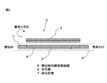
前記正極と前記負極はセパレータを介して捲回した電極捲回体からなり、加えて、
前記負極は、前記セパレータを介在して、前記正極と前記負極とが対向する対向部と、
前記セパレータを介在して、対向する前記正極が存在しない非対向部を有し、そして、
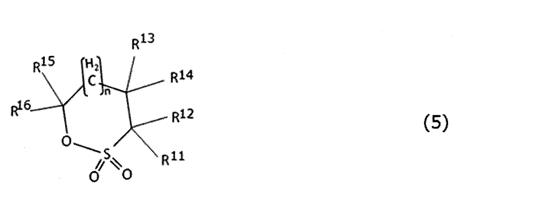
下記式(1)〜(3)の中から選択される化合物の、
前記非対向部における活物質単位質量当たりの含有量をXとし、前記対向部における活物質単位質量当たりの含有量をY、
としたとき、X/Y<0.80であることを特徴とする非水系リチウム型蓄電素子。
[2]前記対向部の負極の膜厚に対する前記非対向部の負極の膜厚の比が、0.80以上0.95以下である、[1]に記載の非水系リチウム型蓄電素子。
[3]前記リチウム化合物は、炭酸リチウム、酸化リチウム、及び水酸化リチウムからなる群から選択される少なくとも一種のリチウム化合物である、[1]又は[2]に記載の非水系リチウム型蓄電素子。
[4]前記負極活物質層の固体7Li−NMRスペクトルにおいて、4ppm〜30ppmの間にピークの最大値を有し、4ppm〜30ppmに観測されるピークの面積より計算されるリチウム量が、前記リチウムイオンを吸蔵した負極活物質層の単位質量当たり0.1mmol/g以上10mmol/g以下である、[1]〜[3]のいずれか一項に記載の非水系リチウム型蓄電素子。
[5]前記負極活物質層の単位体積当たりのBET比表面積が、1m2/cc以上50m2/cc以下である、[1]〜[4]のいずれか一項に記載の非水系リチウム型蓄電素子。
[6]前記正極活物質層が、上記式(1)〜(3)から選択される1種以上の化合物を前記正極物質層の単位質量当たり1.60×10⁻⁴mol/g 以上300×10−4mol/g 以下含有する、[1]〜[5]のいずれか一項に記載の非水系リチウム型蓄電素子。
[7]前記正極が、前記正極活物質層の全質量を基準として、正極活物質以外のリチウム化合物を1質量%以上50質量%以下含有し、かつ、前記非水系電解液のAl濃度が、1ppm以上300ppm以下である、[1]〜[6]のいずれか一項に記載の非水系リチウム型蓄電素子。
[8]前記正極活物質層に含まれる正極活物質が、BJH法により算出した直径20Å以上500Å以下の細孔に由来するメソ孔量をV1(cc/g)とし、MP法により算出した直径20Å未満の細孔に由来するマイクロ孔量をV2(cc/g)とするとき、0.3<V1≦0.8、及び0.5≦V2≦1.0を満たし、かつ、BET法により測定される比表面積が1,500m2/g以上3,000m2/g以下を示す活性炭である、[1]〜[7]のいずれか一項に記載の非水系リチウム型蓄電素子。
[9]前記正極活物質層に含まれる正極活物質が、BJH法により算出した直径20Å以上500Å以下の細孔に由来するメソ孔量V1(cc/g)が0.8<V1≦2.5を満たし、かつMP法により算出した直径20Å未満の細孔に由来するマイクロ孔量V2(cc/g)が0.8<V2≦3.0を満たし、さらに、BET法により測定される比表面積が2,300m2/g以上4,000m2/g以下を示す活性炭である、[1]〜[7]のいずれか一項に記載の非水系リチウム型蓄電素子。
The present invention has been made based on this finding.
That is, the present invention is as follows:
[1] A non-aqueous lithium-type power storage element composed of a positive electrode containing a lithium compound other than an active material, a negative electrode, a separator, and a non-aqueous electrolytic solution containing lithium ions.
The positive electrode has a positive electrode current collector, a positive electrode active material layer composed of an active material and a lithium compound is provided on the current collector, and the negative electrode can occlude and release lithium ions on the negative electrode current collector. Contains active material, and also
The positive electrode and the negative electrode consist of an electrode wound body wound via a separator, and in addition,
The negative electrode has a portion facing the positive electrode and the negative electrode facing each other with the separator interposed therebetween.
With the separator interposed therebetween, it has a non-opposing portion in which the opposite positive electrode does not exist, and
Of the compound selected from the following formulas (1) to (3),
The content per unit mass of the active material in the non-opposing portion is X, and the content per unit mass of the active material in the facing portion is Y.
A non-aqueous lithium-type power storage element, characterized in that X / Y <0.80.
[2] The non-aqueous lithium storage element according to [1], wherein the ratio of the film thickness of the negative electrode of the non-opposing portion to the film thickness of the negative electrode of the facing portion is 0.80 or more and 0.95 or less.
[3] The non-aqueous lithium-type power storage element according to [1] or [2], wherein the lithium compound is at least one lithium compound selected from the group consisting of lithium carbonate, lithium oxide, and lithium hydroxide.
[4] In the solid 7 Li-NMR spectrum of the negative electrode active material layer, the amount of lithium having a maximum peak value between 4 ppm and 30 ppm and calculated from the area of the peak observed at 4 ppm to 30 ppm is the above. The non-aqueous lithium-type power storage element according to any one of [1] to [3], which is 0.1 mmol / g or more and 10 mmol / g or less per unit mass of the negative electrode active material layer in which lithium ions are occluded.
[5] The non-aqueous lithium type according to any one of [1] to [4], wherein the BET specific surface area per unit volume of the negative electrode active material layer is 1 m 2 / cc or more and 50 m 2 / cc or less. Power storage element.
[6] The positive electrode active material layer contains one or more compounds selected from the above formulas (1) to (3) at 1.60 × 10 -4 mol / g or more per unit mass of the positive electrode material layer 300 × The non-aqueous lithium-type power storage element according to any one of [1] to [5], which contains 10 -4 mol / g or less.
[7] The positive electrode contains 1% by mass or more and 50% by mass or less of a lithium compound other than the positive electrode active material based on the total mass of the positive electrode active material layer, and the Al concentration of the non-aqueous electrolyte solution is high. The non-aqueous lithium-type power storage element according to any one of [1] to [6], which is 1 ppm or more and 300 ppm or less.
[8] The amount of mesopores derived from pores having a diameter of 20 Å or more and 500 Å or less calculated by the BJH method for the positive electrode active material contained in the positive electrode active material layer is V1 (cc / g), and the diameter calculated by the MP method When the amount of micropores derived from pores of less than 20 Å is V2 (cc / g), 0.3 <V1 ≦ 0.8 and 0.5 ≦ V2 ≦ 1.0 are satisfied, and the BET method is used. The non-aqueous lithium-type power storage element according to any one of [1] to [7], which is an activated carbon having a measured specific surface area of 1,500 m 2 / g or more and 3,000 m 2 / g or less.
[9] The amount of mesopores V1 (cc / g) of the positive electrode active material contained in the positive electrode active material layer derived from pores having a diameter of 20 Å or more and 500 Å or less calculated by the BJH method is 0.8 <V1 ≦ 2. The ratio of micropores V2 (cc / g) derived from pores having a diameter of less than 20 Å calculated by the MP method and satisfying 5 satisfies 0.8 <V2 ≦ 3.0, and further measured by the BET method. The non-aqueous lithium-type power storage element according to any one of [1] to [7], which is an activated carbon having a surface area of 2,300 m 2 / g or more and 4,000 m 2 / g or less.
本発明に依れば、優れたエネルギー密度と高い入出力特性、さらに高負荷充放電サイクルに対する耐久性を備えた非水系リチウム型蓄電素子を提供することができる。 According to the present invention, it is possible to provide a non-aqueous lithium-type power storage element having excellent energy density, high input / output characteristics, and durability against a high load charge / discharge cycle.
以下、本発明の実施形態につき詳細に説明する。
非水系リチウム型蓄電素子は一般に、正極、負極、セパレータ、電解液、及び外装体を主な構成要素とする。
Hereinafter, embodiments of the present invention will be described in detail.
Non-aqueous lithium-type power storage elements generally include a positive electrode, a negative electrode, a separator, an electrolytic solution, and an exterior body as main components.
[正極]
正極は、正極集電体と、その片面又は両面に存在する正極活物質層とを有する。
また、正極は、蓄電素子組み立て前の正極前駆体として、リチウム化合物を含むことが好ましい。後述のように、本実施形態では蓄電素子組み立て工程内で、負極にリチウムイオンをプレドープすることが好ましいが、そのプレドープ方法としては、前記リチウム化合物を含む正極前駆体、負極、セパレータ、外装体、及び非水系電解液を用いて蓄電素子を組み立てた後に、正極前駆体と負極との間に電圧を印加することが好ましい。前記リチウム化合物は前記正極前駆体の正極集電体上に形成された正極活物質層に含有されることが好ましい。
本明細書中、リチウムドープ工程前における正極状態のことを正極前駆体、リチウムドープ工程後における正極状態のことを正極と定義する。
[Positive electrode]
The positive electrode has a positive electrode current collector and a positive electrode active material layer existing on one side or both sides thereof.
Further, the positive electrode preferably contains a lithium compound as a positive electrode precursor before assembling the power storage element. As will be described later, in the present embodiment, it is preferable to pre-dope the negative electrode with lithium ions in the energy storage element assembly process, but as the pre-doping method, a positive electrode precursor containing the lithium compound, a negative electrode, a separator, an exterior body, and the like. It is preferable to apply a voltage between the positive electrode precursor and the negative electrode after assembling the power storage element using the non-aqueous electrolyte solution. The lithium compound is preferably contained in the positive electrode active material layer formed on the positive electrode current collector of the positive electrode precursor.
In the present specification, the positive electrode state before the lithium doping step is defined as a positive electrode precursor, and the positive electrode state after the lithium doping step is defined as a positive electrode.
[正極活物質層] [Positive electrode active material layer]
前記正極に含まれる正極活物質層は、活性炭を含む正極活物質を含有する。正極活物質層は、これ以外に、必要に応じて、導電性フィラー、結着剤、分散安定剤等の任意成分を含んでいてもよい。
また、正極前駆体の正極活物質層には、正極活物質以外のリチウム化合物が含有されることが好ましい。
The positive electrode active material layer contained in the positive electrode contains a positive electrode active material containing activated carbon. In addition to this, the positive electrode active material layer may contain an optional component such as a conductive filler, a binder, and a dispersion stabilizer, if necessary.
Further, it is preferable that the positive electrode active material layer of the positive electrode precursor contains a lithium compound other than the positive electrode active material.
[正極活物質]
正極活物質は、活性炭を含む。正極活物質としては、活性炭のみを使用してもよく、又は活性炭に加えて、後述するような他の炭素材料を併用してもよい。この炭素材料としては、カーボンナノチューブ、導電性高分子、又は多孔性の炭素材料を使用することがより好ましい。正極活物質には、活性炭を含む1種類以上の炭素材料を混合して使用してもよく、炭素材料以外の材料(例えば、リチウムと遷移金属との複合酸化物等)を含んでもよい。
好ましくは該正極活物質の総量に対する該炭素材料の含有率が50質量%以上であり、より好ましくは70質量%以上である。該炭素材料の含有率が100質量%であることができるが、他の材料の併用による効果を良好に得る観点から、例えば、90質量%以下であることが好ましく、80質量%以下であってもよい。
[Positive electrode active material]
The positive electrode active material contains activated carbon. As the positive electrode active material, only activated carbon may be used, or in addition to activated carbon, other carbon materials as described later may be used in combination. As the carbon material, it is more preferable to use carbon nanotubes, a conductive polymer, or a porous carbon material. The positive electrode active material may be used by mixing one or more kinds of carbon materials including activated carbon, or may contain a material other than the carbon material (for example, a composite oxide of lithium and a transition metal).
The content of the carbon material with respect to the total amount of the positive electrode active material is preferably 50% by mass or more, and more preferably 70% by mass or more. The content of the carbon material can be 100% by mass, but from the viewpoint of obtaining a good effect by using other materials in combination, for example, it is preferably 90% by mass or less, and 80% by mass or less. May be good.
正極活物質として用いる活性炭の種類及びその原料には特に制限はない。しかし、高い入出力特性と、高いエネルギー密度とを両立させるために、活性炭の細孔を最適に制御することが好ましい。具体的には、BJH法により算出した直径20Å以上500Å以下の細孔に由来するメソ孔量をV1(cc/g)、MP法により算出した直径20Å未満の細孔に由来するマイクロ孔量をV2(cc/g)とするとき、
(1)高い入出力特性のためには、0.3<V1≦0.8、及び0.5≦V2≦1.0を満たし、かつ、BET法により測定される比表面積が1,500m2/g以上3,000m2/g以下である活性炭(以下、活性炭1ともいう。)が好ましく、また、
(2)高いエネルギー密度を得るためには、0.8<V1≦2.5、及び0.8<V2≦3.0を満たし、かつ、BET法により測定される比表面積が2,300m2/g以上4,000m2/g以下である活性炭(以下、活性炭2ともいう。)が好ましい。
以下、前記(1)活性炭1及び前記(2)活性炭2について、個別に順次説明していく。
There are no particular restrictions on the type of activated carbon used as the positive electrode active material and its raw material. However, it is preferable to optimally control the pores of the activated carbon in order to achieve both high input / output characteristics and high energy density. Specifically, the amount of mesopores derived from pores having a diameter of 20 Å or more and 500 Å or less calculated by the BJH method is V1 (cc / g), and the amount of micropores derived from pores having a diameter of less than 20 Å calculated by the MP method. When setting to V2 (cc / g)
(1) For high input / output characteristics, 0.3 <V1 ≦ 0.8 and 0.5 ≦ V2 ≦ 1.0 are satisfied, and the specific surface area measured by the BET method is 1,500 m 2. Activated carbon having a / g or more and 3,000 m 2 / g or less (hereinafter, also referred to as activated carbon 1) is preferable.
(2) In order to obtain a high energy density, 0.8 <V1 ≦ 2.5 and 0.8 <V2 ≦ 3.0 are satisfied, and the specific surface area measured by the BET method is 2,300 m 2. Activated carbon having an / g or more and 4,000 m 2 / g or less (hereinafter, also referred to as activated carbon 2) is preferable.
Hereinafter, the (1) activated carbon 1 and the (2) activated
[活性炭1]
活性炭1のメソ孔量V1は、蓄電素子に組み込んだときの入出力特性を大きくする点で、0.3cc/gより大きい値であることが好ましい。他方、正極の嵩密度の低下を抑える点から、0.8cc/g以下であることが好ましい。上記V1は、より好ましくは0.35cc/g以上0.7cc/g以下、更に好ましくは0.4cc/g以上0.6cc/g以下である。
活性炭1のマイクロ孔量V2は、活性炭の比表面積を大きくし、容量を増加させるために、0.5cc/g以上であることが好ましい。他方、活性炭の嵩を抑え、電極としての密度を増加させ、単位体積当たりの容量を増加させるという点から、1.0cc/g以下であることが好ましい。上記V2は、より好ましくは0.6cc/g以上1.0cc/g以下、更に好ましくは0.8cc/g以上1.0cc/g以下である。尚、下限と上限の組み合わせは任意のものであることができる。
[Activated carbon 1]
The mesopore amount V1 of the activated carbon 1 is preferably a value larger than 0.3 cc / g in terms of increasing the input / output characteristics when incorporated in the power storage element. On the other hand, it is preferably 0.8 cc / g or less from the viewpoint of suppressing a decrease in the bulk density of the positive electrode. The above V1 is more preferably 0.35 cc / g or more and 0.7 cc / g or less, and further preferably 0.4 cc / g or more and 0.6 cc / g or less.
The micropore amount V2 of the activated carbon 1 is preferably 0.5 cc / g or more in order to increase the specific surface area and the capacity of the activated carbon. On the other hand, it is preferably 1.0 cc / g or less from the viewpoint of suppressing the bulk of the activated carbon, increasing the density as an electrode, and increasing the capacity per unit volume. The above V2 is more preferably 0.6 cc / g or more and 1.0 cc / g or less, and further preferably 0.8 cc / g or more and 1.0 cc / g or less. The combination of the lower limit and the upper limit can be arbitrary.
マイクロ孔量V2に対するメソ孔量V1の比(V1/V2)は、0.3≦V1/V2≦0.9の範囲であることが好ましい。すなわち、高容量を維持しながら出力特性の低下を抑えることができる程度に、マイクロ孔量に対するメソ孔量の割合を大きくするという点から、V1/V2が0.3以上であることが好ましい。一方で、高出力特性を維持しながら容量の低下を抑えることができる程度に、メソ孔量に対するマイクロ孔量の割合を大きくするという点から、V1/V2は0.9以下であることが好ましい。より好ましいV1/V2の範囲は0.4≦V1/V2≦0.7、更に好ましいV1/V2の範囲は0.55≦V1/V2≦0.7である。尚、下限と上限の組み合わせは任意のものであることができる。 The ratio of the mesopore amount V1 to the micropore amount V2 (V1 / V2) is preferably in the range of 0.3 ≦ V1 / V2 ≦ 0.9. That is, V1 / V2 is preferably 0.3 or more from the viewpoint of increasing the ratio of the mesopore amount to the micropore amount to the extent that the decrease in output characteristics can be suppressed while maintaining a high capacity. On the other hand, V1 / V2 is preferably 0.9 or less from the viewpoint of increasing the ratio of the micropore amount to the mesopore amount to the extent that the decrease in capacitance can be suppressed while maintaining the high output characteristics. .. A more preferable range of V1 / V2 is 0.4 ≦ V1 / V2 ≦ 0.7, and a more preferable range of V1 / V2 is 0.55 ≦ V1 / V2 ≦ 0.7. The combination of the lower limit and the upper limit can be arbitrary.
活性炭1の平均細孔径は、得られる蓄電素子の出力を最大にする点から、17Å以上であることが好ましく、18Å以上であることがより好ましく、20Å以上であることが最も好ましい。また容量を最大にする点から、活性炭1の平均細孔径は25Å以下であることが好ましい。 The average pore diameter of the activated carbon 1 is preferably 17 Å or more, more preferably 18 Å or more, and most preferably 20 Å or more from the viewpoint of maximizing the output of the obtained power storage element. Further, from the viewpoint of maximizing the capacity, the average pore diameter of the activated carbon 1 is preferably 25 Å or less.
活性炭1のBET比表面積は、1,500m2/g以上3,000m2/g以下であることが好ましく、1,500m2/g以上2,500m2/g以下であることがより好ましい。BET比表面積が1,500m2/g以上の場合には、良好なエネルギー密度が得られ易く、他方、BET比表面積が3,000m2/g以下の場合には、電極の強度を保つためにバインダーを多量に入れる必要がないので、電極体積当たりの性能が高くなる。尚、下限と上限の組み合わせは任意のものであることができる。
上記のような特徴を有する活性炭1は、例えば、以下に説明する原料及び処理方法を用いて得ることができる。
BET specific surface area of the activated carbon 1 is preferably from 1,500 m 2 / g or more 3,000 m 2 / g, more preferably not more than 1,500 m 2 / g or more 2,500 m 2 / g. When the BET specific surface area is 1,500 m 2 / g or more, a good energy density can be easily obtained, while when the BET specific surface area is 3,000 m 2 / g or less, in order to maintain the strength of the electrode. Since it is not necessary to add a large amount of binder, the performance per electrode volume is improved. The combination of the lower limit and the upper limit can be arbitrary.
Activated carbon 1 having the above characteristics can be obtained, for example, by using the raw materials and treatment methods described below.
本実施形態では、活性炭1の原料として用いられる炭素源は、特に限定されるものではない。例えば、木材、木粉、ヤシ殻、パルプ製造時の副産物、バガス、廃糖蜜等の植物系原料;泥炭、亜炭、褐炭、瀝青炭、無煙炭、石油蒸留残渣成分、石油ピッチ、コークス、コールタール等の化石系原料;フェノール樹脂、塩化ビニル樹脂、酢酸ビニル樹脂、メラミン樹脂、尿素樹脂、レゾルシノール樹脂、セルロイド、エポキシ樹脂、ポリウレタン樹脂、ポリエステル樹脂、ポリアミド樹脂等の各種合成樹脂;ポリブチレン、ポリブタジエン、ポリクロロプレン等の合成ゴム;その他の合成木材、合成パルプ等、及びこれらの炭化物が挙げられる。これらの原料の中でも、量産対応及びコストの観点から、ヤシ殻、木粉等の植物系原料、及びそれらの炭化物が好ましく、ヤシ殻炭化物が特に好ましい。
これらの原料を上記活性炭1とするための炭化及び賦活の方式としては、例えば、固定床方式、移動床方式、流動床方式、スラリー方式、ロータリーキルン方式等の既知の方式を採用できる。
これらの原料の炭化方法としては、窒素、二酸化炭素、ヘリウム、アルゴン、キセノン、ネオン、一酸化炭素、燃焼排ガス等の不活性ガス、又はこれらの不活性ガスを主成分とした他のガスとの混合ガスを使用して、400〜700℃(好ましくは450〜600℃)程度において、30分〜10時間程度に亘って焼成する方法が挙げられる。
In the present embodiment, the carbon source used as the raw material of the activated carbon 1 is not particularly limited. For example, plant-based raw materials such as wood, wood flour, coconut shells, by-products during pulp production, bagas, waste sugar honey; peat, sub-charcoal, brown charcoal, bituminous charcoal, smokeless charcoal, petroleum distillation residue components, petroleum pitch, coke, coal tar, etc. Fossil raw materials; various synthetic resins such as phenol resin, vinyl chloride resin, vinyl acetate resin, melamine resin, urea resin, resorcinol resin, celluloid, epoxy resin, polyurethane resin, polyester resin, polyamide resin; polybutylene, polybutadiene, polychloroprene, etc. Synthetic rubber; other synthetic wood, synthetic pulp, etc., and carbonized products thereof. Among these raw materials, plant-based raw materials such as coconut shells and wood flour and their carbides are preferable, and coconut shell carbides are particularly preferable, from the viewpoint of mass production and cost.
As a carbonization and activation method for converting these raw materials into the activated carbon 1, for example, known methods such as a fixed bed method, a moving bed method, a fluidized bed method, a slurry method, and a rotary kiln method can be adopted.
Examples of the carbonization method for these raw materials include inert gases such as nitrogen, carbon dioxide, helium, argon, xenone, neon, carbon monoxide, and combustion exhaust gas, or other gases containing these inert gases as main components. Examples thereof include a method of firing at about 400 to 700 ° C. (preferably 450 to 600 ° C.) for about 30 minutes to 10 hours using a mixed gas.
上記炭化方法により得られた炭化物の賦活方法としては、水蒸気、二酸化炭素、酸素等の賦活ガスを用いて焼成するガス賦活法が好ましく用いられる。このうち、賦活ガスとして、水蒸気又は二酸化炭素を使用する方法が好ましい。
この賦活方法では、賦活ガスを0.5〜3.0kg/h(好ましくは0.7〜2.0kg/h)の割合で供給しながら、上記炭化物を3〜12時間(好ましくは5〜11時間、更に好ましくは6〜10時間)かけて800〜1,000℃まで昇温して賦活するのが好ましい。
更に、上記炭化物の賦活処理に先立ち、予め上記炭化物を1次賦活してもよい。この1次賦活では、通常、炭素材料を水蒸気、二酸化炭素、酸素等の賦活ガスを用いて、900℃未満の温度で焼成してガス賦活する方法が、好ましく採用できる。
上記炭化方法における焼成温度及び焼成時間と、上記賦活方法における賦活ガス供給量、昇温速度及び最高賦活温度とを適宜組み合わせることにより、本実施形態において使用できる、上記の特徴を有する活性炭1を製造することができる。
As a method for activating the carbide obtained by the above carbonization method, a gas activation method in which the carbide is fired using an activation gas such as steam, carbon dioxide, or oxygen is preferably used. Of these, a method using steam or carbon dioxide as the activating gas is preferable.
In this activation method, the above-mentioned carbide is supplied for 3 to 12 hours (preferably 5 to 11) while supplying the activation gas at a ratio of 0.5 to 3.0 kg / h (preferably 0.7 to 2.0 kg / h). It is preferable to activate by raising the temperature to 800 to 1,000 ° C. over time, more preferably 6 to 10 hours).
Further, the carbide may be first activated in advance prior to the activation treatment of the carbide. In this primary activation, a method in which a carbon material is usually calcined at a temperature of less than 900 ° C. using an activation gas such as steam, carbon dioxide, or oxygen to activate the gas can be preferably adopted.
By appropriately combining the calcination temperature and calcination time in the carbonization method with the activation gas supply amount, temperature rise rate, and maximum activation temperature in the activation method, activated carbon 1 having the above characteristics that can be used in the present embodiment is produced. can do.
活性炭1の平均粒子径は、2〜20μmであることが好ましい。
上記平均粒子径が2μm以上であると、活物質層の密度が高いために電極体積当たりの容量が高くなる傾向がある。ここで、平均粒子径が小さいと耐久性が低いという欠点を招来する場合があるが、平均粒子径が2μm以上であればそのような欠点が生じ難い。一方で、平均粒子径が20μm以下であると、高速充放電には適合し易くなる傾向がある。上記平均粒子径は、より好ましくは2〜15μmであり、更に好ましくは3〜10μmである。上記平均粒子径の範囲の上限と下限は、任意に組み合わせることができる。
The average particle size of the activated carbon 1 is preferably 2 to 20 μm.
When the average particle size is 2 μm or more, the capacity per electrode volume tends to be high because the density of the active material layer is high. Here, if the average particle size is small, the durability may be low, but if the average particle size is 2 μm or more, such a defect is unlikely to occur. On the other hand, when the average particle size is 20 μm or less, it tends to be easily adapted to high-speed charging / discharging. The average particle size is more preferably 2 to 15 μm, still more preferably 3 to 10 μm. The upper and lower limits of the average particle size range can be arbitrarily combined.
[活性炭2]
活性炭2のメソ孔量V1は、蓄電素子に組み込んだときの出力特性を大きくする観点から、0.8cc/gより大きい値であることが好ましい。他方、V1は、蓄電素子の容量の低下を抑える観点から、2.5cc/g以下であることが好ましい。上記V1は、より好ましくは1.00cc/g以上2.0cc/g以下、さらに好ましくは、1.2cc/g以上1.8cc/g以下である。
[Activated carbon 2]
The mesopore amount V1 of the activated
他方、活性炭2のマイクロ孔量V2は、活性炭の比表面積を大きくし、容量を増加させるために、0.8cc/gより大きい値であることが好ましい。一方、V2は、活性炭の電極としての密度を増加させ、単位体積当たりの容量を増加させるという観点から、3.0cc/g以下、より好ましくは1.0cc/g超2.5cc/g以下、更に好ましくは1.5cc/g以上2.5cc/g以下である。
On the other hand, the micropore amount V2 of the activated
上述したメソ孔量及びマイクロ孔量を有する活性炭2は、従来の電気二重層キャパシタ又はリチウムイオンキャパシタ用として使用されていた活性炭よりもBET比表面積が高いものである。活性炭2のBET比表面積の具体的な値としては、2,300m2/g以上4,000m2/g以下であることが好ましい。BET比表面積の下限としては、3,000m2/g以上であることがより好ましく、3,200m2/g以上であることが更に好ましい。一方、BET比表面積の上限としては、3,800m2/g以下であることがより好ましい。BET比表面積が2,300m2/g以上の場合には、良好なエネルギー密度が得られ易く、他方、BET比表面積が4,000m2/g以下の場合には、電極の強度を保つためにバインダーを多量に入れる必要がないので、電極体積当たりの性能が高くなる。
なお、活性炭2のV1、V2及びBET比表面積については、それぞれ上記で説明された好適な範囲の上限と下限を、任意に組み合わせることができる。
The activated
Regarding the V1, V2 and BET specific surface areas of the activated
上記のような特徴を有する活性炭2は、例えば以下に説明するような原料及び処理方法を用いて得ることができる。
活性炭2の原料として用いられる炭素源としては、通常活性炭原料として用いられる炭素源であれば特に限定されるものではなく、例えば、木材、木粉、ヤシ殻等の植物系原料;石油ピッチ、コークス等の化石系原料;フェノール樹脂、フラン樹脂、塩化ビニル樹脂、酢酸ビニル樹脂、メラミン樹脂、尿素樹脂、レゾルシノール樹脂等の各種合成樹脂等が挙げられる。これらの原料の中でも、フェノール樹脂、及びフラン樹脂は、高比表面積の活性炭を作製するのに適しており特に好ましい。
The carbon source used as a raw material for activated
これらの原料を炭化する方式、或いは賦活処理時の加熱方法としては、例えば、固定床方式、移動床方式、流動床方式、スラリー方式、ロータリーキルン方式等の公知の方式が挙げられる。加熱時の雰囲気は窒素、二酸化炭素、ヘリウム、アルゴン等の不活性ガス、又はこれらの不活性ガスを主成分として他のガスとの混合したガスが用いられる。炭化温度は400〜700℃(下限について、好ましくは450℃以上、更に好ましくは500℃以上。上限について、好ましくは650℃以下)程度で0.5〜10時間程度焼成することが好ましい。 Examples of the method of carbonizing these raw materials or the heating method at the time of activation treatment include known methods such as a fixed bed method, a moving bed method, a fluidized bed method, a slurry method, and a rotary kiln method. As the atmosphere at the time of heating, an inert gas such as nitrogen, carbon dioxide, helium, or argon, or a gas containing these inert gases as a main component and mixed with other gases is used. It is preferable to bake at a carbonization temperature of about 400 to 700 ° C. (the lower limit is preferably 450 ° C. or higher, more preferably 500 ° C. or higher, and the upper limit is preferably 650 ° C. or lower) for about 0.5 to 10 hours.
上記炭化処理後の炭化物の賦活方法としては、水蒸気、二酸化炭素、酸素等の賦活ガスを用いて焼成するガス賦活法、及びアルカリ金属化合物と混合した後に加熱処理を行うアルカリ金属賦活法があるが、高比表面積の活性炭を作製するにはアルカリ金属賦活法が好ましい。
この賦活方法では、炭化物とKOH、NaOH等のアルカリ金属化合物との質量比が1:1以上(アルカリ金属化合物の量が、炭化物の量と同じかこれよりも多い量)となるように混合した後に、不活性ガス雰囲気下で600〜900℃(好ましくは650℃〜850℃)の範囲において、0.5〜5時間加熱を行い、その後アルカリ金属化合物を酸及び水により洗浄除去し、更に乾燥を行う。
Examples of the method for activating the carbide after the carbonization treatment include a gas activation method in which the carbide is fired using an activated gas such as steam, carbon dioxide, and oxygen, and an alkali metal activation method in which heat treatment is performed after mixing with an alkali metal compound. The alkali metal activation method is preferable for producing activated carbon having a high specific surface area.
In this activation method, the carbides were mixed so that the mass ratio of the carbides to the alkali metal compounds such as KOH and NaOH was 1: 1 or more (the amount of the alkali metal compounds was the same as or larger than the amount of the carbides). Later, heating is carried out in the range of 600 to 900 ° C. (preferably 650 ° C. to 850 ° C.) in an inert gas atmosphere for 0.5 to 5 hours, after which the alkali metal compound is washed and removed with acid and water, and further dried. I do.
炭化物とアルカリ金属化合物の質量比(=炭化物:アルカリ金属化合物)は1:1以上が好ましいことを先記したが、アルカリ金属化合物の量が増えるほど、メソ孔量が増えるが、質量比1:3.5付近を境に急激に孔量が増える傾向があるので、質量比は1:3よりアルカリ金属化合物が増えることが好ましく、1:5.5以下であることが好ましい。質量比はアルカリ金属化合物が増えるほど孔量が大きくなるが、その後の洗浄等の処理効率を考慮すると上記範囲であることが好ましい。
なお、マイクロ孔量を大きくし、メソ孔量を大きくしないためには、賦活する際に炭化物の量を多めにしてKOHと混合するとよい。マイクロ孔量及びメソ孔量の双方を大きくするためには、KOHの量を多めに使用するとよい。また、主としてメソ孔量を大きくするためには、アルカリ賦活処理を行った後に水蒸気賦活を行うことが好ましい。
活性炭2の平均粒子径は2μm以上20μm以下であることが好ましく、より好ましくは3μm以上10μm以下である。
I mentioned earlier that the mass ratio of carbide to alkali metal compound (= carbide: alkali metal compound) is preferably 1: 1 or more. However, as the amount of alkali metal compound increases, the amount of mesopores increases, but the mass ratio is 1: 1. Since the amount of pores tends to increase sharply around 3.5, the mass ratio is preferably more than 1: 3 and the amount of the alkali metal compound is preferably 1: 5.5 or less. The mass ratio increases as the amount of the alkali metal compound increases, but it is preferably in the above range in consideration of treatment efficiency such as subsequent cleaning.
In order to increase the amount of micropores and not to increase the amount of mesopores, it is advisable to increase the amount of carbides at the time of activation and mix with KOH. In order to increase both the amount of micropores and the amount of mesopores, it is advisable to use a large amount of KOH. Further, in order to mainly increase the amount of mesopores, it is preferable to perform steam activation after performing alkali activation treatment.
The average particle size of the activated
[活性炭の使用態様]
活性炭1及び2は、それぞれ、1種の活性炭であってもよいし、2種以上の活性炭の混合物であって上記した各々の特性値を混合物全体として示すものであってもよい。
上記の活性炭1及び2は、これらのうちのいずれか一方を選択して使用してもよいし、両者を混合して使用してもよい。
正極活物質は、活性炭1及び2以外の材料(例えば、前記特定のV1及び/若しくはV2を有さない活性炭、又は活性炭以外の材料(例えば、リチウムと遷移金属との複合酸化物等))を含んでもよい。例示の態様において、活性炭1の含有量、又は活性炭2の含有量、又は活性炭1及び2の合計含有量が、それぞれ、全正極活物質の50質量%より多いことが好ましく、70質量%以上がより好ましく、90質量%以上が更に好ましく、100質量%であることが最も好ましい。
[Usage of activated carbon]
As the activated
The positive electrode active material is a material other than activated carbon 1 and 2 (for example, activated carbon that does not have the specific V1 and / or V2, or a material other than activated carbon (for example, a composite oxide of lithium and a transition metal)). It may be included. In an exemplary embodiment, the content of activated carbon 1, the content of activated
正極活物質層における正極活物質の含有割合は、正極前駆体における正極活物質層の全質量を基準として、35質量%以上95質量%以下であることが好ましい。正極活物質の含有割合の上限としては、45質量%以上であることがより好ましく、55質量%以上であることがさらに好ましい。他方、正極活物質の含有割合の下限としては、90質量%以下であることがより好ましく、80質量%以下であることが更に好ましい。この範囲の含有割合とすることにより、好適な充放電特性を発揮する。 The content ratio of the positive electrode active material in the positive electrode active material layer is preferably 35% by mass or more and 95% by mass or less based on the total mass of the positive electrode active material layer in the positive electrode precursor. The upper limit of the content ratio of the positive electrode active material is more preferably 45% by mass or more, and further preferably 55% by mass or more. On the other hand, the lower limit of the content ratio of the positive electrode active material is more preferably 90% by mass or less, and further preferably 80% by mass or less. By setting the content ratio in this range, suitable charge / discharge characteristics are exhibited.
[リチウム化合物]
本実施形態の正極前駆体の正極活物質層には、正極活物質以外のリチウム化合物が含有されることが好ましい。また、本実施形態の正極の正極活物質層には、正極活物質以外のリチウム化合物が含有される。
前記リチウム化合物としては、後述のリチウムドープ工程において正極で分解し、リチウムイオンを放出することが可能である、炭酸リチウム、酸化リチウム、水酸化リチウム、フッ化リチウム、塩化リチウム、シュウ化リチウム、ヨウ化リチウム、窒化リチウム、シュウ酸リチウム、及び酢酸リチウムから選択される1種以上が好適に用いられる。中でも、炭酸リチウム、酸化リチウム、及び水酸化リチウムがより好適であり、空気中での取り扱いが可能であり、かつ吸湿性が低いという観点から炭酸リチウムがさらに好適に用いられる。このようなリチウム化合物は、電圧の印加によって分解し、負極へのリチウムドープのドーパント源として機能するとともに、正極活物質層において空孔を形成するから、電解液の保持性に優れ、イオン伝導性に優れる正極を形成することができる。
また、電圧によって分解したリチウム化合物は負極の非対向部よりも対向部へ優先的にドープされるため、負極の非対向部へのリチウムドープが抑制され、負極電位を高くすることが可能である。本明細書における負極電位は、金属リチウム基準の電位のことを示す。
[Lithium compound]
The positive electrode active material layer of the positive electrode precursor of the present embodiment preferably contains a lithium compound other than the positive electrode active material. Further, the positive electrode active material layer of the positive electrode of the present embodiment contains a lithium compound other than the positive electrode active material.
The lithium compound can be decomposed at the positive electrode in the lithium doping step described later to release lithium ions, such as lithium carbonate, lithium oxide, lithium hydroxide, lithium fluoride, lithium chloride, lithium oxalate, and iodine. One or more selected from lithium carbonate, lithium nitride, lithium oxalate, and lithium acetate are preferably used. Among them, lithium carbonate, lithium oxide, and lithium hydroxide are more preferable, and lithium carbonate is more preferably used from the viewpoint that it can be handled in the air and has low hygroscopicity. Such a lithium compound decomposes when a voltage is applied, functions as a dopant source for lithium doping to the negative electrode, and forms pores in the positive electrode active material layer. Therefore, the electrolytic solution has excellent retention and ionic conductivity. It is possible to form an excellent positive electrode.
Further, since the lithium compound decomposed by the voltage is preferentially doped into the non-opposing portion of the negative electrode over the non-opposing portion of the negative electrode, lithium doping into the non-opposing portion of the negative electrode is suppressed, and the negative electrode potential can be increased. .. The negative electrode potential in the present specification indicates a potential based on metallic lithium.
[正極前駆体のリチウム化合物]
リチウム化合物は、粒子状であることが好ましい。正極前駆体に含有されるリチウム化合物の平均粒子径は0.1μm以上100μm以下であることが好ましい。正極前駆体に含有されるリチウム化合物の平均粒子径の上限としては50μm以下であることがより好ましく、20μm以下であることが更に好ましく、10μm以下であることが最も好ましい。他方、正極前駆体に含有されるリチウム化合物の平均粒子径の下限としては0.3μm以上であることがより好ましく、0.5μm以上であることが更に好ましい。リチウム化合物の平均粒子径が0.1μm以上であれば、正極におけるリチウム化合物の酸化反応後に残る空孔が電解液を保持するのに十分な容積を有することとなるため、高負荷充放電特性が向上する。リチウム化合物の平均粒子径が100μm以下であれば、リチウム化合物の表面積が過度に小さくはならないから、該リチウム化合物の酸化反応の速度を確保することができる。リチウム化合物の平均粒子径の範囲の上限と下限は、任意に組み合わせることができる。
リチウム化合物の微粒子化には、様々な方法を用いることができる。例えば、ボールミル、ビーズミル、リングミル、ジェットミル、ロッドミル等の粉砕機を使用することができる。
[Lithium compound of positive electrode precursor]
The lithium compound is preferably in the form of particles. The average particle size of the lithium compound contained in the positive electrode precursor is preferably 0.1 μm or more and 100 μm or less. The upper limit of the average particle size of the lithium compound contained in the positive electrode precursor is more preferably 50 μm or less, further preferably 20 μm or less, and most preferably 10 μm or less. On the other hand, the lower limit of the average particle size of the lithium compound contained in the positive electrode precursor is more preferably 0.3 μm or more, and further preferably 0.5 μm or more. When the average particle size of the lithium compound is 0.1 μm or more, the pores remaining after the oxidation reaction of the lithium compound in the positive electrode have a sufficient volume to hold the electrolytic solution, so that the high load charge / discharge characteristics are exhibited. improves. When the average particle size of the lithium compound is 100 μm or less, the surface area of the lithium compound does not become excessively small, so that the rate of oxidation reaction of the lithium compound can be ensured. The upper and lower limits of the range of the average particle size of the lithium compound can be arbitrarily combined.
Various methods can be used for atomizing the lithium compound. For example, a crusher such as a ball mill, a bead mill, a ring mill, a jet mill, or a rod mill can be used.
正極前駆体の正極活物質層におけるリチウム化合物の含有割合は、正極前駆体における正極活物質層の全質量を基準として、5質量%以上60質量%以下であることが好ましく、10質量%以上50質量%以下であることがより好ましい。この範囲の含有割合とすることにより、負極へのドーパント源として好適な機能を発揮するとともに、正極に適当な程度の多孔性を付与することができ、両者相俟って高負荷充放電効率に優れる蓄電素子を与えることができ、好ましい。この含有割合の範囲の上限と下限は、任意に組み合わせることができる。 The content ratio of the lithium compound in the positive electrode active material layer of the positive electrode precursor is preferably 5% by mass or more and 60% by mass or less based on the total mass of the positive electrode active material layer in the positive electrode precursor, and is preferably 10% by mass or more and 50% by mass or more. It is more preferably mass% or less. By setting the content ratio in this range, it is possible to exert a suitable function as a dopant source for the negative electrode and to impart an appropriate degree of porosity to the positive electrode, and both of them achieve high load charge / discharge efficiency. It is preferable because it can provide an excellent power storage element. The upper and lower limits of this content ratio range can be arbitrarily combined.
[正極のリチウム化合物]
正極は、正極活物質以外のリチウム化合物を含有する。正極が含有する、正極活物質以外のリチウム化合物の平均粒子径をX1とするとき、0.1μm≦X1≦10μmであることが好ましい。更に好ましくは、0.5μm≦X1≦5μmである。X1が0.1μm以上の場合、高負荷充放電サイクルで生成するフッ素イオンを吸着することにより高負荷充放電サイクル特性が向上する。X1が10μm以下の場合、高負荷充放電サイクルで生成するフッ素イオンとの反応面積が増加するため、フッ素イオンの吸着を効率良く行うことができる。
[Lithium compound of positive electrode]
The positive electrode contains a lithium compound other than the positive electrode active material. When the average particle size of the lithium compound other than the positive electrode active material contained in the positive electrode is X 1 , it is preferably 0.1 μm ≦ X 1 ≦ 10 μm. More preferably, it is 0.5 μm ≦ X 1 ≦ 5 μm. When X 1 is 0.1 μm or more, the high load charge / discharge cycle characteristics are improved by adsorbing the fluorine ions generated in the high load charge / discharge cycle. When X 1 is 10 μm or less, the reaction area with the fluorine ions generated in the high load charge / discharge cycle increases, so that the adsorption of fluorine ions can be performed efficiently.
正極が含有する、正極活物質以外のリチウム化合物は、正極における正極活物質層の全質量を基準として、1質量%以上50質量%以下であることを特徴とし、2.5質量%以上25質量%以下であることがより好ましい。リチウム化合物量が1質量%以上であると、高温環境下における正極上での電解液溶媒の分解反応を炭酸リチウムが抑制するため、高温耐久性が向上し、2.5質量%以上でその効果が顕著になる。また、リチウム化合物量が50質量%以下であると、正極活物質間の電子伝導性がリチウム化合物により阻害されることが比較的小さいため、高い入出力特性を示し、25質量%以下であると、特に入出力特性の観点から特に好ましい。尚、下限と上限の組み合わせは任意のものであることができる。 The lithium compound contained in the positive electrode other than the positive electrode active material is characterized by being 1% by mass or more and 50% by mass or less based on the total mass of the positive electrode active material layer in the positive electrode, and is 2.5% by mass or more and 25% by mass. More preferably, it is less than%. When the amount of the lithium compound is 1% by mass or more, lithium carbonate suppresses the decomposition reaction of the electrolytic solution solvent on the positive electrode in a high temperature environment, so that the high temperature durability is improved, and the effect is improved when the amount is 2.5% by mass or more. Becomes noticeable. Further, when the amount of the lithium compound is 50% by mass or less, the electron conductivity between the positive electrode active materials is relatively small to be inhibited by the lithium compound, so that high input / output characteristics are exhibited, and the amount is 25% by mass or less. , Especially preferable from the viewpoint of input / output characteristics. The combination of the lower limit and the upper limit can be arbitrary.
[正極中のリチウム化合物の同定方法]
正極中に含まれるリチウム化合物の同定方法は特に限定されないが、例えば、下記の方法により同定することができる。リチウム化合物の同定には、以下に記載する複数の解析手法を組み合わせて同定することが好ましい。
以下に記載するSEM−EDX、ラマン、XPSを測定する際には、アルゴンボックス中で非水系リチウム型蓄電素子を解体して正極を取り出し、正極表面に付着した電解質を洗浄した後に測定を行うことが好ましい。正極の洗浄方法については、正極表面に付着した電解質を洗い流せればよいため、ジメチルカーボネート、エチルメチルカーボネート、ジエチルカーボネート等のカーボネート溶媒が好適に利用できる。洗浄方法としては、例えば、正極質量の50〜100倍のジエチルカーボネート溶媒に正極を10分間以上浸漬させ、その後溶媒を取り替えて再度正極を浸漬させる。その後正極をジエチルカーボネートから取り出し、真空乾燥(温度:0〜200℃、圧力:0〜20kPa、時間:1〜40時間の範囲で正極中のジエチルカーボネートの残存が1質量%以下になる条件とする。ジエチルカーボネートの残存量については、後述する蒸留水洗浄、液量調整後の水のGC/MSを測定し、予め作成した検量線を基に定量することができる。)させた後に、前記SEM−EDX、ラマン、XPSの解析を実施する。
[Method for identifying lithium compounds in positive electrode]
The method for identifying the lithium compound contained in the positive electrode is not particularly limited, but for example, it can be identified by the following method. For identification of the lithium compound, it is preferable to identify by combining a plurality of analysis methods described below.
When measuring SEM-EDX, Raman, and XPS described below, disassemble the non-aqueous lithium-type power storage element in an argon box, take out the positive electrode, clean the electrolyte adhering to the positive electrode surface, and then perform the measurement. Is preferable. As for the method for cleaning the positive electrode, since the electrolyte adhering to the surface of the positive electrode may be washed away, a carbonate solvent such as dimethyl carbonate, ethyl methyl carbonate, or diethyl carbonate can be preferably used. As a cleaning method, for example, the positive electrode is immersed in a diethyl carbonate solvent having a mass of 50 to 100 times the positive electrode for 10 minutes or more, and then the solvent is replaced and the positive electrode is immersed again. After that, the positive electrode is taken out from diethyl carbonate, and vacuum dried (temperature: 0 to 200 ° C., pressure: 0 to 20 kPa, time: 1 to 40 hours, and the condition is that the residual diethyl carbonate in the positive electrode is 1% by mass or less. The residual amount of diethyl carbonate can be quantified based on the calibration line prepared in advance by measuring the GC / MS of the water after washing with distilled water and adjusting the liquid amount, which will be described later.) -Perform EDX, Raman, and XPS analysis.
後述するイオンクロマトグラフィーについては、正極を蒸留水で洗浄した後の水を解析することにより陰イオンを同定することができる。
前記解析手法にてリチウム化合物を同定できなかった場合、その他の解析手法として、固体7Li−NMR、XRD(X線回折)、TOF−SIMS(飛行時間型二次イオン質量分析)、AES(オージェ電子分光)、TPD/MS(加熱発生ガス質量分析)、DSC(示差走査熱量分析)等を用いることにより、リチウム化合物を同定することもできる。
Regarding ion chromatography described later, anions can be identified by analyzing the water after washing the positive electrode with distilled water.
If the lithium compound cannot be identified by the above analysis method, other analysis methods include solid 7 Li-NMR, XRD (X-ray diffraction), TOF-SIMS (time-of-flight secondary ion mass spectrometry), and AES (Auger). Lithium compounds can also be identified by using electron spectroscopy), TPD / MS (heat-of-flight mass spectrometry), DSC (differential scanning calorie analysis), and the like.
[SEM−EDX]
酸素を含有するリチウム化合物及び正極活物質は、観察倍率を1000倍〜4000倍にして測定した正極表面のSEM−EDX画像による酸素マッピングにより判別できる。SEM−EDX画像の測定例として、加速電圧を10kV、エミッション電流を1μA、測定画素数を256×256ピクセル、積算回数を50回として測定できる。試料の帯電を防止するために、金、白金、オスミウム等を真空蒸着やスパッタリング等の方法により表面処理することもできる。SEM−EDX画像の測定方法については、明るさは最大輝度に達する画素がなく、明るさの平均値が輝度40%〜60%の範囲に入るように輝度及びコントラストを調整することが好ましい。得られた酸素マッピングに対し、明るさの平均値を基準に二値化した明部を面積50%以上含む粒子をリチウム化合物とする。
[SEM-EDX]
The oxygen-containing lithium compound and the positive electrode active material can be identified by oxygen mapping using an SEM-EDX image of the positive electrode surface measured at an observation magnification of 1000 to 4000 times. As a measurement example of the SEM-EDX image, the acceleration voltage can be measured as 10 kV, the emission current as 1 μA, the number of measurement pixels as 256 × 256 pixels, and the number of integrations as 50 times. In order to prevent the sample from being charged, gold, platinum, osmium or the like can be surface-treated by a method such as vacuum deposition or sputtering. Regarding the method for measuring the SEM-EDX image, it is preferable to adjust the brightness and contrast so that the brightness does not reach the maximum brightness and the average value of the brightness is in the range of 40% to 60%. Particles containing 50% or more of bright areas binarized with respect to the obtained oxygen mapping based on the average value of brightness are designated as lithium compounds.
[ラマン]
炭酸イオンからなるリチウム化合物及び正極活物質は、観察倍率を1000倍〜4000倍にして測定した正極表面のラマンイメージングにより判別できる。測定条件の例として、励起光を532nm、励起光強度を1%、対物レンズの長作動を50倍、回折格子を1800gr/mm、マッピング方式を点走査(スリット65mm、ビニング5pix)、1mmステップ、1点当たりの露光時間を3秒、積算回数を1回、ノイズフィルター有りの条件にて測定することができる。測定したラマンスペクトルについて、1071〜1104cm−1の範囲で直線のベースラインを設定し、ベースラインより正の値を炭酸イオンのピークとして面積を算出し、頻度を積算するが、この時にノイズ成分をガウス型関数で近似した炭酸イオンピーク面積に対する頻度を前記炭酸イオンの頻度分布から差し引く。
[Raman]
The lithium compound composed of carbonate ions and the positive electrode active material can be identified by Raman imaging of the positive electrode surface measured at an observation magnification of 1000 to 4000 times. As an example of measurement conditions, the excitation light is 532 nm, the excitation light intensity is 1%, the long operation of the objective lens is 50 times, the diffraction grating is 1800 gr / mm, the mapping method is point scanning (slit 65 mm, binning 5 pix), 1 mm step, The exposure time per point can be measured for 3 seconds, the number of integrations can be measured once, and the measurement can be performed under the condition of having a noise filter. For the measured Raman spectrum, a straight baseline is set in the range of 1071-1104 cm -1 , the area is calculated with a positive value from the baseline as the peak of carbonate ion, and the frequency is integrated. At this time, the noise component is added. The frequency for the carbonate ion peak area approximated by the Gaussian function is subtracted from the carbonate ion frequency distribution.
[XPS]
リチウムの電子状態をXPSにより解析することによりリチウムの結合状態を判別することができる。測定条件の例として、X線源を単色化AlKα、X線ビーム径を100μmφ(25W、15kV)、パスエネルギーをナロースキャン:58.70eV、帯電中和を有り、スイープ数をナロースキャン:10回(炭素、酸素)20回(フッ素)30回(リン)40回(リチウム)50回(ケイ素)、エネルギーステップをナロースキャン:0.25eVの条件にて測定できる。XPSの測定前に正極の表面をスパッタリングにてクリーニングすることが好ましい。スパッタリングの条件として例えば、加速電圧1.0kV、2mm×2mmの範囲を1分間(SiO2換算で1.25nm/min)の条件にて正極の表面をクリーニングすることができる。得られたXPSスペクトルについて、Li1sの結合エネルギー50〜54eVのピークをLiO2又はLi−C結合、55〜60eVのピークをLiF、Li2CO3、LixPOyFz(式中、x、y、zは1〜6の整数である)、C1sの結合エネルギー285eVのピークをC−C結合、286eVのピークをC−O結合、288eVのピークをCOO、290〜292eVのピークをCO3 2−、C−F結合、O1sの結合エネルギー527〜530eVのピークをO2−(Li2O)、531〜532eVのピークをCO、CO3、OH、POx(式中、xは1〜4の整数である)、SiOx(式中、xは1〜4の整数である)、533eVのピークをC−O、SiOx(式中、xは1〜4の整数である)、F1sの結合エネルギー685eVのピークをLiF、687eVのピークをC−F結合、LixPOyFz(式中、x、y、zは1〜6の整数である)、PF6 −、P2pの結合エネルギーについて、133eVのピークをPOx(式中、xは1〜4の整数である)、134〜136eVのピークをPFx(式中、xは1〜6の整数である)、Si2pの結合エネルギー99eVのピークをSi、シリサイド、101〜107eVのピークをSixOy(式中、x、yは任意の整数である)として帰属することができる。得られたスペクトルについて、ピークが重なる場合には、ガウス関数又はローレンツ関数を仮定してピーク分離し、スペクトルを帰属することが好ましい。前記で得られた電子状態の測定結果及び存在元素比の結果から、存在するリチウム化合物を同定することができる。
[XPS]
The bonding state of lithium can be determined by analyzing the electronic state of lithium by XPS. As an example of measurement conditions, the X-ray source is monochromatic AlKα, the X-ray beam diameter is 100 μmφ (25 W, 15 kV), the path energy is narrow scan: 58.70 eV, there is charge neutralization, and the number of sweeps is narrow scan: 10 times. (Carbon, oxygen) 20 times (fluorine) 30 times (phosphorus) 40 times (lithium) 50 times (silicon), energy steps can be measured under the conditions of narrow scan: 0.25 eV. It is preferable to clean the surface of the positive electrode by sputtering before measuring XPS. As the sputtering conditions, for example, the surface of the positive electrode can be cleaned under the condition of an acceleration voltage of 1.0 kV, 2 mm × 2 mm for 1 minute (1.25 nm / min in terms of SiO 2 ). Regarding the obtained XPS spectrum, the peak of Li1s binding energy of 50 to 54 eV is LiO 2 or Li-C bond, and the peak of 55 to 60 eV is LiF, Li 2 CO 3 , Li x PO y F z (x in the formula, x, y, z is an integer from 1 to 6), the peak of C1s of the bond energy 285 eV C-C bonds, the peak of 286 eV CO bond, COO peaks 288 eV, the peak of 290~292eV CO 3 2 − , CF binding, binding energy of O1s 527 to 530 eV peak is O 2- (Li 2 O), 531 to 532 eV peak is CO, CO 3 , OH, PO x (in the formula, x is 1 to 4) (In the formula, x is an integer of 1 to 4), SiO x (in the formula, x is an integer of 1 to 4), the peak of 533 eV is CO, SiO x (in the formula, x is an integer of 1 to 4), F1s. the peak of binding energy 685eV LiF, a peak of 687 eV C-F bond, Li x PO y F z (wherein, x, y, z are an integer of 1 to 6), PF 6 -, the binding energy of P2p For, the peak of 133 eV is PO x (in the formula, x is an integer of 1 to 4), the peak of 134 to 136 eV is PF x (in the formula, x is an integer of 1 to 6), and the binding energy of Si2p. the peak of 99 eV Si, silicides, (wherein, x, y are arbitrary integers) peaks 101~107eV Si x O y can be assigned as. When the peaks of the obtained spectrum overlap, it is preferable to separate the peaks assuming a Gaussian function or a Lorentz function and assign the spectra. The existing lithium compound can be identified from the measurement result of the electronic state and the result of the presence element ratio obtained above.
[イオンクロマトグラフィー]
正極の蒸留水洗浄液をイオンクロマトグラフィー(IC)で解析することにより、水中に溶出したアニオン種を同定することができる。使用するカラムとしては、イオン交換型、イオン排除型、逆相イオン対型を使用することができる。検出器としては、電気伝導度検出器、紫外可視吸光光度検出器、電気化学検出器等を使用することができ、検出器の前にサプレッサーを設置するサプレッサー方式、またはサプレッサーを配置せずに電気伝導度の低い溶液を溶離液に用いるノンサプレッサー方式を用いることができる。また、質量分析計や荷電化粒子検出を検出器と組み合わせて測定することもできるため、SEM−EDX、ラマン、XPSの解析結果から同定されたリチウム化合物を基に適切なカラム、検出器を組み合わせることが好ましい。
サンプルの保持時間は、使用するカラムや溶離液等の条件が決まれば、イオン種成分毎に一定であり、また、ピークのレスポンスの大きさはイオン種毎に異なるが濃度に比例する。トレーサビリティーが確保された既知濃度の標準液を予め測定しておくことでイオン種成分の定性と定量が可能となる。
[Ion chromatography]
By analyzing the distilled water washing solution of the positive electrode by ion chromatography (IC), the anion species eluted in water can be identified. As the column to be used, an ion exchange type, an ion exclusion type, and a reverse phase ion pair type can be used. As the detector, an electric conductivity detector, an ultraviolet visible absorptiometric detector, an electrochemical detector, etc. can be used, and a suppressor method in which a suppressor is installed in front of the detector, or electricity without a suppressor. A non-suppressor method using a solution having low conductivity as an eluent can be used. In addition, since mass spectrometer and charged particle detection can be measured in combination with a detector, an appropriate column and detector are combined based on the lithium compound identified from the analysis results of SEM-EDX, Raman, and XPS. Is preferable.
The retention time of the sample is constant for each ion species component if conditions such as the column to be used and the eluent are determined, and the magnitude of the peak response differs for each ion species but is proportional to the concentration. By measuring in advance a standard solution having a known concentration that ensures traceability, it is possible to qualitatively and quantify the ionic species component.
[リチウム化合物の定量方法]
正極中に含まれるリチウム化合物の定量方法を以下に記載する。
正極を有機溶媒で洗浄し、その後蒸留水で洗浄し、蒸留水での洗浄前後の正極質量変化からリチウム化合物を定量することができる。測定する正極の面積は特に制限されないが、測定のばらつきを軽減するという観点から5cm2以上200cm2以下であることが好ましく、更に好ましくは25cm2以上150cm2以下である。面積が5cm2以上あれば測定の再現性が確保される。面積が200cm2以下であればサンプルの取扱い性に優れる。有機溶媒による洗浄については正極表面に堆積した非水系電解液分解物を除去できれば良いため、有機溶媒は特に限定されないが、前記リチウム化合物の溶解度が2%以下である有機溶媒を用いることでリチウム化合物の溶出が抑制されるため好ましい。例えば、メタノール、アセトン等の極性溶媒が好適に用いられる。
[Method for quantifying lithium compounds]
The method for quantifying the lithium compound contained in the positive electrode is described below.
The positive electrode can be washed with an organic solvent, then washed with distilled water, and the lithium compound can be quantified from the change in positive mass before and after washing with distilled water. Although area measurement is positive is not particularly limited, it is preferably, more preferably 25 cm 2 or more 150 cm 2 or less from the viewpoint of reducing the variation in measurement is 5 cm 2 or more 200 cm 2 or less. If the area is 5 cm 2 or more, the reproducibility of measurement is ensured. If the area is 200 cm 2 or less, the handling of the sample is excellent. For cleaning with an organic solvent, the organic solvent is not particularly limited as long as the non-aqueous electrolyte decomposition product deposited on the surface of the positive electrode can be removed. However, by using an organic solvent having a solubility of the lithium compound of 2% or less, the lithium compound can be used. It is preferable because the elution of the solvent is suppressed. For example, polar solvents such as methanol and acetone are preferably used.
正極の洗浄方法は、正極の質量に対し50〜100倍のメタノール溶液に正極を3日間以上十分に浸漬させる。この時、メタノールが揮発しないよう容器に蓋をするなどの対策を施すことが好ましい。その後正極をメタノールから取り出し、真空乾燥(温度:100〜200℃、圧力:0〜10kPa、時間:5〜20時間の範囲で正極中のメタノールの残存が1質量%以下になる条件とする。メタノールの残存量については、後述する蒸留水洗浄後の水のGC/MSを測定し、予め作成した検量線を基に定量することができる。)し、その時の正極の質量をM0[g]とする。続いて、正極の質量の100倍(100M0[g])の蒸留水に正極を3日間以上十分に浸漬させる。この時、蒸留水が揮発しないよう容器に蓋をする等の対策を施すことが好ましい。3日間以上浸漬させた後、蒸留水から正極を取り出し(前述のイオンクロマトグラフィーを測定する場合は、蒸留水の量が100M0[g]になるように液量を調整する。)、前記のメタノール洗浄と同様に真空乾燥する。この時の正極の質量をM1[g]とし、続いて、得られた正極の集電体の質量を測定するため、スパチュラ、ブラシ、刷毛等を用いて集電体上の正極活物質層を取り除く。得られた正極集電体の質量をM2[g]とすると、正極中に含まれるリチウム化合物の質量%Zは、下記数式(1):
[正極活物質層の任意成分]
本実施形態における正極活物質層は、必要に応じて、正極活物質及びリチウム化合物の他に、導電性フィラー、結着剤、分散安定剤等の任意成分を含んでいてもよい。
導電性フィラーとしては、特に制限されるものではないが、例えば、アセチレンブラック、ケッチェンブラック、気相成長炭素繊維、黒鉛、カーボンナノチューブ、これらの混合物等を用いることができる。導電性フィラーの使用量は、正極活物質100質量部に対して、好ましくは0質量部以上30質量部以下である。より好ましくは0.01質量部以上20質量部以下、さらに好ましくは1質量部以上15質量部以下である。導電性フィラーの使用量が30質量部よりも多くなると、正極活物質層における正極活物質の含有割合が少なくなるために、正極活物質層体積当たりのエネルギー密度が低下するので好ましくない。
結着剤としては、特に制限されるものではないが、例えばPVdF(ポリフッ化ビニリデン)、PTFE(ポリテトラフルオロエチレン)、ポリイミド、ラテックス、スチレン−ブタジエン共重合体、フッ素ゴム、アクリル共重合体等を用いることができる。結着剤の使用量は、正極活物質100質量部に対して、好ましくは1質量部以上30質量部以下、より好ましくは3質量部以上27質量部以下、さらに好ましくは5質量部以上25質量部以下である。結着剤の使用量が1質量部以上であれば、十分な電極強度が発現される。一方で結着剤の使用量が30質量部以下であれば、正極活物質へのイオンの出入り及び拡散を阻害せず、高い入出力特性が発現される。
分散安定剤としては、特に制限されるものではないが、例えばPVP(ポリビニルピロリドン)、PVA(ポリビニルアルコール)、セルロース誘導体等を用いることができる。分散安定剤の使用量は、正極活物質100質量部に対して、好ましくは、0質量部又は0.1質量部以上、10質量部以下である。分散安定剤の使用量が10質量部以下であれば、正極活物質へのイオンの出入り及び拡散を阻害せず、高い入出力特性が発現される。
[Arbitrary component of positive electrode active material layer]
If necessary, the positive electrode active material layer in the present embodiment may contain optional components such as a conductive filler, a binder, and a dispersion stabilizer in addition to the positive electrode active material and the lithium compound.
The conductive filler is not particularly limited, and for example, acetylene black, ketjen black, vapor-grown carbon fiber, graphite, carbon nanotubes, a mixture thereof and the like can be used. The amount of the conductive filler used is preferably 0 parts by mass or more and 30 parts by mass or less with respect to 100 parts by mass of the positive electrode active material. It is more preferably 0.01 parts by mass or more and 20 parts by mass or less, and further preferably 1 part by mass or more and 15 parts by mass or less. If the amount of the conductive filler used is more than 30 parts by mass, the content ratio of the positive electrode active material in the positive electrode active material layer decreases, and the energy density per volume of the positive electrode active material layer decreases, which is not preferable.
The binder is not particularly limited, but for example, PVdF (polyvinylidene fluoride), PTFE (polytetrafluoroethylene), polyimide, latex, styrene-butadiene copolymer, fluororubber, acrylic copolymer and the like. Can be used. The amount of the binder used is preferably 1 part by mass or more and 30 parts by mass or less, more preferably 3 parts by mass or more and 27 parts by mass or less, and further preferably 5 parts by mass or more and 25 parts by mass with respect to 100 parts by mass of the positive electrode active material. It is less than a part. When the amount of the binder used is 1 part by mass or more, sufficient electrode strength is exhibited. On the other hand, when the amount of the binder used is 30 parts by mass or less, high input / output characteristics are exhibited without inhibiting the entry / exit and diffusion of ions into the positive electrode active material.
The dispersion stabilizer is not particularly limited, but for example, PVP (polyvinylpyrrolidone), PVA (polyvinyl alcohol), a cellulose derivative and the like can be used. The amount of the dispersion stabilizer used is preferably 0 parts by mass or 0.1 parts by mass or more and 10 parts by mass or less with respect to 100 parts by mass of the positive electrode active material. When the amount of the dispersion stabilizer used is 10 parts by mass or less, high input / output characteristics are exhibited without inhibiting the entry / exit and diffusion of ions into the positive electrode active material.
[正極集電体]
本実施形態における正極集電体を構成する材料としては、電子伝導性が高く、電解液への溶出及び電解質又はイオンとの反応等による劣化が起こらない材料であれば特に制限はないが、金属箔が好ましい。本実施の形態の非水系リチウム型蓄電素子における正極集電体としては、アルミニウム箔が特に好ましい。
該金属箔は凹凸や貫通孔を持たない通常の金属箔でもよいし、エンボス加工、ケミカルエッチング、電解析出法、ブラスト加工等を施した凹凸を有する金属箔でもよいし、エキスパンドメタル、パンチングメタル、エッチング箔等の貫通孔を有する金属箔でもよい。
正極集電体の厚みは、正極の形状及び強度を十分に保持できれば特に制限はないが、例えば、1〜100μmが好ましい。
[Positive current collector]
The material constituting the positive electrode current collector in the present embodiment is not particularly limited as long as it has high electron conductivity and does not deteriorate due to elution into the electrolytic solution and reaction with the electrolyte or ions. Foil is preferred. Aluminum foil is particularly preferable as the positive electrode current collector in the non-aqueous lithium power storage device of the present embodiment.
The metal foil may be an ordinary metal foil having no irregularities or through holes, a metal foil having irregularities subjected to embossing, chemical etching, electrolytic precipitation, blasting, etc., expanded metal, punching metal, etc. , A metal foil having through holes such as an etching foil may be used.
The thickness of the positive electrode current collector is not particularly limited as long as the shape and strength of the positive electrode can be sufficiently maintained, but is preferably 1 to 100 μm, for example.
[正極前駆体の製造]
本実施形態において、非水系リチウム型蓄電素子の正極となる正極前駆体は、既知のリチウムイオン電池、電気二重層キャパシタ等における電極の製造技術によって製造することが可能である。例えば、正極活物質及びリチウム化合物、並びに必要に応じて使用されるその他の任意成分を水又は有機溶剤中に分散又は溶解してスラリー状の塗工液を調製し、この塗工液を正極集電体上の片面又は両面に塗工して塗膜を形成し、これを乾燥することにより正極前駆体を得ることが出来る。さらに、得られた正極前駆体にプレスを施して、正極活物質層の膜厚又は嵩密度を調整してもよい。代替的には、溶剤を使用せずに、正極活物質及びリチウム化合物、並びに必要に応じて使用されるその他の任意成分を乾式で混合し、得られた混合物をプレス成型した後、導電性接着剤を用いて正極集電体に貼り付ける方法も可能である。
[Manufacturing of positive electrode precursor]
In the present embodiment, the positive electrode precursor serving as the positive electrode of the non-aqueous lithium-type power storage element can be manufactured by a technique for manufacturing electrodes in known lithium ion batteries, electric double layer capacitors, and the like. For example, a positive electrode active material, a lithium compound, and other optional components used as necessary are dispersed or dissolved in water or an organic solvent to prepare a slurry coating solution, and this coating solution is collected as a positive electrode. A positive electrode precursor can be obtained by applying a coating film on one or both sides of an electric body to form a coating film and drying the coating film. Further, the obtained positive electrode precursor may be pressed to adjust the film thickness or bulk density of the positive electrode active material layer. Alternatively, without the use of a solvent, the positive electrode active material and the lithium compound, and any other optional components used as needed, are dry mixed, the resulting mixture is press molded and then conductively bonded. It is also possible to attach the agent to the positive electrode current collector.
前記正極前駆体の塗工液は、正極活物質を含む各種材料粉末の一部若しくは全部をドライブレンドし、次いで水若しくは有機溶媒、及び/又はそれらに結着剤若しくは分散安定剤が溶解又は分散した液状又はスラリー状の物質を追加して調製してもよい。また、水又は有機溶媒に結着剤又は分散安定剤が溶解又は分散した液状又はスラリー状の物質の中に、正極活物質を含む各種材料粉末を追加して、塗工液を調製してもよい。前記ドライブレンドする方法として、例えばボールミル等を使用して正極活物質及びリチウム化合物、並びに必要に応じて導電性フィラーを予備混合して、導電性の低いリチウム化合物に導電性フィラーをコーティングさせる予備混合をしてもよい。これにより、後述のリチウムドープ工程において正極前駆体でリチウム化合物が分解し易くなる。前記塗工液の溶媒に水を使用する場合には、リチウム化合物を加えることで塗工液がアルカリ性になることもあるため、必要に応じてpH調整剤を添加してもよい。 The coating liquid of the positive electrode precursor is a dry blend of a part or all of various material powders including a positive electrode active material, and then water or an organic solvent and / or a binder or a dispersion stabilizer is dissolved or dispersed therein. The liquid or slurry-like substance may be added and prepared. Further, even if various material powders containing a positive electrode active material are added to a liquid or slurry-like substance in which a binder or a dispersion stabilizer is dissolved or dispersed in water or an organic solvent to prepare a coating liquid. Good. As the method of dry blending, for example, a positive electrode active material and a lithium compound are premixed using a ball mill or the like, and if necessary, a conductive filler is premixed, and a lithium compound having low conductivity is coated with the conductive filler. You may do. As a result, the lithium compound is easily decomposed in the positive electrode precursor in the lithium doping step described later. When water is used as the solvent of the coating liquid, the coating liquid may become alkaline by adding the lithium compound, so that a pH adjuster may be added if necessary.
前記正極前駆体の塗工液の調製には、特に制限されるものではないが、好適にはホモディスパーや多軸分散機、プラネタリーミキサー、薄膜旋回型高速ミキサー等の分散機等を用いることが出来る。良好な分散状態の塗工液を得るためには、周速1m/s以上50m/s以下で分散することが好ましい。周速が1m/s以上であれば、各種材料が良好に溶解又は分散するため好ましい。また、周速が50m/s以下であれば、分散による熱又はせん断力により各種材料が破壊されることなく、再凝集が生じることがないため好ましい。
前記塗工液の分散度は、粒ゲージで測定した粒度が0.1μm以上100μm以下であることが好ましい。分散度の上限としては、より好ましくは粒度が80μm以下、さらに好ましくは粒度が50μm以下である。粒度が0.1μm未満では、正極活物質を含む各種材料粉末の粒子径以下のサイズとなり、塗工液作製時に材料を破砕していることになり好ましくない。また、粒度が100μm以下であれば、塗工液吐出時の詰まりや塗膜のスジ発生等がなく、安定に塗工ができる。
The preparation of the coating liquid for the positive electrode precursor is not particularly limited, but preferably a disperser such as a homodisper, a multi-axis disperser, a planetary mixer, or a thin film swirling high-speed mixer is used. Can be done. In order to obtain a coating liquid in a good dispersed state, it is preferable to disperse at a peripheral speed of 1 m / s or more and 50 m / s or less. When the peripheral speed is 1 m / s or more, various materials are preferably dissolved or dispersed. Further, when the peripheral speed is 50 m / s or less, various materials are not destroyed by heat or shearing force due to dispersion, and reaggregation does not occur, which is preferable.
The dispersity of the coating liquid is preferably such that the particle size measured by the grain gauge is 0.1 μm or more and 100 μm or less. The upper limit of the dispersity is more preferably a particle size of 80 μm or less, and further preferably a particle size of 50 μm or less. If the particle size is less than 0.1 μm, the size is smaller than the particle size of various material powders containing the positive electrode active material, and the material is crushed during the preparation of the coating liquid, which is not preferable. Further, when the particle size is 100 μm or less, stable coating can be performed without clogging at the time of discharging the coating liquid or generation of streaks on the coating film.
前記正極前駆体の塗工液の粘度(ηb)は、1,000mPa・s以上20,000mPa・s以下が好ましく、より好ましくは1,500mPa・s以上10,000mPa・s以下、さらに好ましくは1,700mPa・s以上5,000mPa・s以下である。粘度(ηb)が1,000mPa・s以上であれば、塗膜形成時の液ダレが抑制され、塗膜幅及び膜厚が良好に制御できる。また、粘度(ηb)が20,000mPa・s以下であれば、塗工機を用いた際の塗工液の流路における圧力損失が少なく安定に塗工でき、また所望の塗膜厚み以下に制御できる。
また、該塗工液のTI値(チクソトロピーインデックス値)は、1.1以上が好ましく、より好ましくは1.2以上、さらに好ましくは1.5以上である。TI値が1.1以上であれば、塗膜幅及び膜厚が良好に制御できる。
The viscosity (ηb) of the coating liquid of the positive electrode precursor is preferably 1,000 mPa · s or more and 20,000 mPa · s or less, more preferably 1,500 mPa · s or more and 10,000 mPa · s or less, still more preferably 1. , 700 mPa · s or more and 5,000 mPa · s or less. When the viscosity (ηb) is 1,000 mPa · s or more, liquid dripping during coating film formation is suppressed, and the coating film width and film thickness can be satisfactorily controlled. Further, when the viscosity (ηb) is 20,000 mPa · s or less, the pressure loss in the flow path of the coating liquid when using the coating machine is small and stable coating can be performed, and the coating film thickness is less than the desired one. Can be controlled.
The TI value (thixotropy index value) of the coating liquid is preferably 1.1 or more, more preferably 1.2 or more, and further preferably 1.5 or more. When the TI value is 1.1 or more, the coating film width and the film thickness can be satisfactorily controlled.
前記正極前駆体の塗膜の形成は特に制限されるものではないが、好適にはダイコーターやコンマコーター、ナイフコーター、グラビア塗工機等の塗工機を用いることが出来る。塗膜は単層塗工で形成してもよいし、多層塗工で形成してもよい。多層塗工の場合には、塗膜各層内のリチウム化合物の含有量が異なるように塗工液組成を調整してもよい。また、塗工速度は0.1m/分以上100m/分以下であることが好ましく、より好ましくは0.5m/分以上70m/分以下、さらに好ましくは1m/分以上50m/分以下である。塗工速度が0.1m/分以上であれば、安定に塗工出来る。他方、塗工速度が100m/分以下であれば、塗工精度を十分に確保できる。 The formation of the coating film of the positive electrode precursor is not particularly limited, but a coating machine such as a die coater, a comma coater, a knife coater, or a gravure coating machine can be preferably used. The coating film may be formed by a single-layer coating or a multi-layer coating. In the case of multi-layer coating, the coating liquid composition may be adjusted so that the content of the lithium compound in each layer of the coating film is different. The coating speed is preferably 0.1 m / min or more and 100 m / min or less, more preferably 0.5 m / min or more and 70 m / min or less, and further preferably 1 m / min or more and 50 m / min or less. If the coating speed is 0.1 m / min or more, stable coating can be performed. On the other hand, if the coating speed is 100 m / min or less, sufficient coating accuracy can be ensured.
前記正極前駆体の塗膜の乾燥については、特に制限されるものではないが、好適には熱風乾燥や赤外線(IR)乾燥等の乾燥方法を用いることが出来る。塗膜の乾燥は、単一の温度で乾燥させてもよいし、多段的に温度を変えて乾燥させてもよい。また、複数の乾燥方法を組み合わせて塗膜を乾燥させてもよい。乾燥温度は、25℃以上200℃以下であることが好ましく、より好ましくは40℃以上180℃以下、さらに好ましくは50℃以上160℃以下である。乾燥温度が25℃以上であれば、塗膜中の溶媒を十分に揮発させることが出来る。他方、乾燥温度が200℃以下であれば、急激な溶媒の揮発による塗膜のヒビ割れやマイグレーションによる結着剤の偏在、及び正極集電体や正極活物質層の酸化を抑制できる。 The drying of the coating film of the positive electrode precursor is not particularly limited, but a drying method such as hot air drying or infrared (IR) drying can be preferably used. The coating film may be dried at a single temperature, or may be dried at different temperatures in multiple stages. Further, the coating film may be dried by combining a plurality of drying methods. The drying temperature is preferably 25 ° C. or higher and 200 ° C. or lower, more preferably 40 ° C. or higher and 180 ° C. or lower, and further preferably 50 ° C. or higher and 160 ° C. or lower. When the drying temperature is 25 ° C. or higher, the solvent in the coating film can be sufficiently volatilized. On the other hand, when the drying temperature is 200 ° C. or lower, cracks in the coating film due to rapid volatilization of the solvent, uneven distribution of the binder due to migration, and oxidation of the positive electrode current collector and the positive electrode active material layer can be suppressed.
前記正極前駆体のプレスには、特に制限されるものではないが、好適には油圧プレス機、真空プレス機等のプレス機を用いることが出来る。正極活物質層の膜厚、嵩密度及び電極強度は、後述するプレス圧力、隙間、及びプレス部の表面温度により調整できる。
プレス圧力は0.5kN/cm以上20kN/cm以下が好ましく、より好ましくは1kN/cm以上10kN/cm以下、さらに好ましくは2kN/cm以上7kN/cm以下である。プレス圧力が0.5kN/cm以上であれば、電極強度を十分に高くできる。他方、プレス圧力が20kN/cm以下であれば、正極前駆体に撓みやシワが生じることがなく、所望の正極活物質層膜厚や嵩密度に調整できる。
また、プレスロール同士の隙間は、所望の正極活物質層の膜厚や嵩密度となるように乾燥後の正極前駆体膜厚に応じて任意の値を設定できる。さらに、プレス速度は正極前駆体に撓みやシワが生じない任意の速度に設定できる。
また、プレス部の表面温度は室温でもよいし、必要によりプレス部を加熱してもよい。加熱する場合のプレス部の表面温度の下限は、使用する結着剤の融点マイナス60℃以上が好ましく、より好ましくは融点マイナス45℃以上、さらに好ましくは融点マイナス30℃以上である。他方、加熱する場合のプレス部の表面温度の上限は、使用する結着剤の融点プラス50℃以下が好ましく、より好ましくは融点プラス30℃以下、さらに好ましくは融点プラス20℃以下である。例えば、結着剤にPVdF(ポリフッ化ビニリデン:融点150℃)を用いた場合、プレス部の表面を90℃以上200℃以下に加温することが好ましく、より好ましく105℃以上180℃以下、さらに好ましくは120℃以上170℃以下にプレス部の表面を加熱することである。また、結着剤にスチレン−ブタジエン共重合体(融点100℃)を用いた場合、プレス部の表面を40℃以上150℃以下に加温することが好ましく、より好ましくは55℃以上130℃以下、さらに好ましくは70℃以上120℃以下にプレス部の表面を加温することである。
The press of the positive electrode precursor is not particularly limited, but a press machine such as a hydraulic press machine or a vacuum press machine can be preferably used. The film thickness, bulk density, and electrode strength of the positive electrode active material layer can be adjusted by the press pressure, the gap, and the surface temperature of the press portion, which will be described later.
The press pressure is preferably 0.5 kN / cm or more and 20 kN / cm or less, more preferably 1 kN / cm or more and 10 kN / cm or less, and further preferably 2 kN / cm or more and 7 kN / cm or less. When the press pressure is 0.5 kN / cm or more, the electrode strength can be sufficiently increased. On the other hand, when the press pressure is 20 kN / cm or less, the positive electrode precursor does not bend or wrinkle, and the desired positive electrode active material layer film thickness and bulk density can be adjusted.
Further, the gap between the press rolls can be set to an arbitrary value according to the film thickness of the positive electrode precursor after drying so as to have a desired film thickness and bulk density of the positive electrode active material layer. Further, the pressing speed can be set to an arbitrary speed at which the positive electrode precursor does not bend or wrinkle.
Further, the surface temperature of the press portion may be room temperature, or the press portion may be heated if necessary. The lower limit of the surface temperature of the pressed portion at the time of heating is preferably a melting point of the binder to be used of minus 60 ° C. or higher, more preferably a melting point of minus 45 ° C. or higher, and further preferably a melting point of minus 30 ° C. or higher. On the other hand, the upper limit of the surface temperature of the pressed portion when heating is preferably the melting point of the binder used plus 50 ° C. or lower, more preferably the melting point plus 30 ° C. or lower, and further preferably the melting point plus 20 ° C. or lower. For example, when PVdF (polyvinylidene fluoride: melting point 150 ° C.) is used as the binder, it is preferable to heat the surface of the pressed portion to 90 ° C. or higher and 200 ° C. or lower, more preferably 105 ° C. or higher and 180 ° C. or lower, and further. It is preferable to heat the surface of the press portion to 120 ° C. or higher and 170 ° C. or lower. When a styrene-butadiene copolymer (melting point 100 ° C.) is used as the binder, the surface of the pressed portion is preferably heated to 40 ° C. or higher and 150 ° C. or lower, more preferably 55 ° C. or higher and 130 ° C. or lower. More preferably, the surface of the pressed portion is heated to 70 ° C. or higher and 120 ° C. or lower.
結着剤の融点は、DSC(Differential Scanning Calorimetry、示差走査熱量分析)の吸熱ピーク位置で求めることができる。例えば、パーキンエルマー社製の示差走査熱量計「DSC7」を用いて、試料樹脂10mgを測定セルにセットし、窒素ガス雰囲気中で、温度30℃から10℃/分の昇温速度で250℃まで昇温し、昇温過程における吸熱ピーク温度が融点となる。
また、プレス圧力、隙間、速度、及びプレス部の表面温度の条件を変えながら複数回プレスを実施してもよい。
The melting point of the binder can be determined from the endothermic peak position of DSC (Differential Scanning Calorimetry, differential scanning calorimetry). For example, using a differential scanning calorimeter "DSC7" manufactured by PerkinElmer, 10 mg of sample resin is set in a measurement cell, and the temperature rises from 30 ° C. to 250 ° C. at a heating rate of 10 ° C./min in a nitrogen gas atmosphere. The temperature is raised, and the endothermic peak temperature in the temperature raising process becomes the melting point.
Further, the press may be performed a plurality of times while changing the conditions of the press pressure, the gap, the speed, and the surface temperature of the press portion.
前記正極活物質層の膜厚は、正極集電体の片面当たり20μm以上200μm以下であることが好ましく、より好ましくは片面当たり25μm以上100μm以下であり、更に好ましくは30μm以上80μm以下である。この膜厚が20μm以上であれば、十分な充放電容量を発現することができる。他方、この膜厚が200μm以下であれば、電極内のイオン拡散抵抗を低く維持することができるため、十分な出力特性が得られるとともに、セル体積を縮小することができ、従ってエネルギー密度を高めることができる。上記正極活物質層の膜厚の範囲の上限と下限は、任意に組み合わせることができる。なお、集電体が貫通孔や凹凸を有する場合における正極活物質層の膜厚とは、集電体の貫通孔や凹凸を有していない部分の片面当たりの膜厚の平均値をいう。 The film thickness of the positive electrode active material layer is preferably 20 μm or more and 200 μm or less per one side of the positive electrode current collector, more preferably 25 μm or more and 100 μm or less per one side, and further preferably 30 μm or more and 80 μm or less. When this film thickness is 20 μm or more, a sufficient charge / discharge capacity can be developed. On the other hand, when this film thickness is 200 μm or less, the ion diffusion resistance in the electrode can be kept low, so that sufficient output characteristics can be obtained, the cell volume can be reduced, and therefore the energy density can be increased. be able to. The upper and lower limits of the film thickness range of the positive electrode active material layer can be arbitrarily combined. The film thickness of the positive electrode active material layer when the current collector has through holes or irregularities refers to the average value of the film thickness per side of the portion of the current collector that does not have through holes or irregularities.
[正極]
後述のリチウムドープ工程後の正極における正極活物質層の嵩密度は、0.25g/cm3以上であることが好ましく、より好ましくは0.30g/cm3以上1.3g/cm3以下の範囲である。正極活物質層の嵩密度が0.25g/cm3以上であれば、高いエネルギー密度を発現でき、蓄電素子の小型化を達成できる。また、この嵩密度が1.3g/cm3以下であれば、正極活物質層内の空孔における電解液の拡散が十分となり、高い出力特性が得られる。
[Positive electrode]
The bulk density of the positive electrode active material layer in the positive electrode after the lithium doping step described later is preferably 0.25 g / cm 3 or more, more preferably 0.30 g / cm 3 or more and 1.3 g / cm 3 or less. Is. When the bulk density of the positive electrode active material layer is 0.25 g / cm 3 or more, a high energy density can be exhibited and the miniaturization of the power storage element can be achieved. Further, when the bulk density is 1.3 g / cm 3 or less, the electrolytic solution is sufficiently diffused in the pores in the positive electrode active material layer, and high output characteristics can be obtained.
[正極活物質層中の化合物]
本発明に係る正極活物質層は、下記式(1)〜(3)から選択される1種以上の化合物を該正極物質層の単位質量当たり1.60×10⁻⁴mol/g〜100×10−4mol/g含有することが好ましい。
The positive electrode active material layer according to the present invention contains one or more compounds selected from the following formulas (1) to (3) at 1.60 × 10 -4 mol / g to 100 × per unit mass of the positive electrode material layer. It preferably contains 10 -4 mol / g.
式(1)中、R1は、炭素数1〜4のアルキレン基、又は炭素数1〜4のハロゲン化アルキレン基であり、X1、X2はそれぞれ独立に−(COO)n(ここで、nは0又は1である。)である。
特に好ましい化合物は、
LiOC2H4OLi、LiOC3H6OLi、LiOC2H4OCOOLi、LiOCOOC3H6OLi、LiOCOOC2H4OCOOLi及びLiOCOOC3H6OCOOLiで表される化合物である。
In the formula (1), R 1 is an alkylene group having 1 to 4 carbon atoms or a halogenated alkylene group having 1 to 4 carbon atoms, and X 1 and X 2 are independently − (COO) n (here). , N is 0 or 1.).
Particularly preferred compounds are
It is a compound represented by LiOC 2 H 4 OLi, LiOC 3 H 6 OLi, LiOC 2 H 4 OCOOLi, LiOCOOC 3 H 6 OLi, LiOCOOC 2 H 4 OCOOLi and LiOCOOC 3 H 6 OCOOLi.
式(2)中、R1は、炭素数1〜4のアルキレン基、又は炭素数1〜4のハロゲン化アルキレン基であり、R2は水素、炭素数1〜10のアルキル基、炭素数1〜10のモノ若しくはポリヒドロキシアルキル基、炭素数2〜10のアルケニル基、炭素数2〜10のモノ又はポリヒドロキシアルケニル基、炭素数3〜6のシクロアルキル基、及びアリール基からなる群から選択される基であり、X1、X2はそれぞれ独立に−(COO)n(ここで、nは0又は1である。)である。
特に好ましい化合物は、
LiOC2H4OH、LiOC3H6OH、LiOC2H4OCOOH、LiOC3H6OCOOH、LiOCOOC2H4OCOOH、LiOCOOC3H6OCOOH、LiOC2H4OCH3、LiOC3H6OCH3、LiOC2H4OCOOCH3、LiOC3H6OCOOCH3、LiOCOOC2H4OCOOCH3、LiOCOOC3H6OCOOCH3、LiOC2H4OC2H5、LiOC3H6OC2H5、LiOC2H4OCOOC2H5、LiOC3H6OCOOC2H5、LiOCOOC2H4OCOOC2H5、LiOCOOC3H6OCOOC2H5で表される化合物である。
In the formula (2), R 1 is an alkylene group having 1 to 4 carbon atoms or a halogenated alkylene group having 1 to 4 carbon atoms, and R 2 is hydrogen, an alkyl group having 1 to 10 carbon atoms, and 1 carbon atom. Select from the group consisting of a mono or polyhydroxyalkyl group having 10 to 10 carbon atoms, an alkenyl group having 2 to 10 carbon atoms, a mono or polyhydroxyalkenyl group having 2 to 10 carbon atoms, a cycloalkyl group having 3 to 6 carbon atoms, and an aryl group. X 1 and X 2 are independently − (COO) n (where n is 0 or 1).
Particularly preferred compounds are
LiOC 2 H 4 OH, LiOC 3 H 6 OH, LiOC 2 H 4 OCOOH, LiOC 3 H 6 OCOOH, LiOCOC 2 H 4 OCOOH, LiOCOC 3 H 6 OCOOH, LiOC 2 H 4 OCH 3 , LiOC 3 H 6 OCH 3 LiOC 2 H 4 OCOOCH 3, LiOC 3
式(3)中、R1は、炭素数1〜4のアルキレン基、又は炭素数1〜4のハロゲン化アルキレン基であり、R2、R3はそれぞれ独立に水素、炭素数1〜10のアルキル基、炭素数1〜10のモノ若しくはポリヒドロキシアルキル基、炭素数2〜10のアルケニル基、炭素数2〜10のモノ又はポリヒドロキシアルケニル基、炭素数3〜6のシクロアルキル基、及びアリール基からなる群から選択される基であり、X1、X2はそれぞれ独立に−(COO)n(ここで、nは0又は1である。)である。
特に好ましい化合物は、
HOC2H4OH、HOC3H6OH、HOC2H4OCOOH、HOC3H6OCOOH、HOCOOC2H4OCOOH、HOCOOC3H6OCOOH、HOC2H4OCH3、HOC3H6OCH3、HOC2H4OCOOCH3、HOC3H6OCOOCH3、HOCOOC2H4OCOOCH3、HOCOOC3H6OCOOCH3、HOC2H4OC2H5、HOC3H6OC2H5、HOC2H4OCOOC2H5、HOC3H6OCOOC2H5、HOCOOC2H4OCOOC2H5、HOCOOC3H6OCOOC2H5、CH3OC2H4OCH3、CH3OC3H6OCH3、CH3OC2H4OCOOCH3、CH3OC3H6OCOOCH3、CH3OCOOC2H4OCOOCH3、CH3OCOOC3H6OCOOCH3、CH3OC2H4OC2H5、CH3OC3H6OC2H5、CH3OC2H4OCOOC2H5、CH3OC3H6OCOOC2H5、CH3OCOOC2H4OCOOC2H5、CH3OCOOC3H6OCOOC2H5、C2H5OC2H4OC2H5、C2H5OC3H6OC2H5、C2H5OC2H4OCOOC2H5、C2H5OC3H6OCOOC2H5、C2H5OCOOC2H4OCOOC2H5、C2H5OCOOC3H6OCOOC2H5
で表される化合物である。
In the formula (3), R 1 is an alkylene group having 1 to 4 carbon atoms or a halogenated alkylene group having 1 to 4 carbon atoms, and R 2 and R 3 are independently hydrogen and 1 to 10 carbon atoms, respectively. Alkyl groups, mono or polyhydroxyalkyl groups with 1 to 10 carbon atoms, alkenyl groups with 2 to 10 carbon atoms, mono or polyhydroxyalkenyl groups with 2 to 10 carbon atoms, cycloalkyl groups with 3 to 6 carbon atoms, and aryl It is a group selected from the group consisting of groups, and X 1 and X 2 are independently − (COO) n (where n is 0 or 1).
Particularly preferred compounds are
HOC 2 H 4 OH, HOC 3 H 6 OH, HOC 2 H 4 OCOOH, HOC 3 H 6 OCOOH, HOCOC 2 H 4 OCOOH, HOCOC 3 H 6 OCOOH, HOC 2 H 4 OCH 3 , HOC 3 H 6 OCH 3 HOC 2 H 4 OCOOCH 3, HOC 3
It is a compound represented by.
本発明における上記の前記化合物を正極活物質層内に含有させるための方法としては、例えば、
正極活物質層に前記化合物を混合する方法、
正極活物質層に前記化合物を吸着させる方法、
正極活物質層に前記化合物を電気化学的に析出させる方法
等が挙げられる。
中でも、非水系電解液中に、分解してこれらの前記化合物を生成し得る前駆体を含有させておき、蓄電素子を作製する工程における前記前駆体の分解反応を利用して、正極活物質層内に前記化合物を堆積させる方法が好ましい。
As a method for incorporating the above-mentioned compound in the positive electrode active material layer in the present invention, for example,
A method of mixing the compound with the positive electrode active material layer,
A method of adsorbing the compound on the positive electrode active material layer,
Examples thereof include a method of electrochemically precipitating the compound on the positive electrode active material layer.
Above all, a positive electrode active material layer is contained in a non-aqueous electrolytic solution that can be decomposed to produce these compounds, and the decomposition reaction of the precursor in the step of producing a power storage element is utilized. A method of depositing the compound inside is preferable.
前記化合物を形成する前駆体としては、エチレンカーボネート、プロピレンカーボネート、ブチレンカーボネート、ビニレンカーボネートおよびフルオロエチレンカーボネートから選択される少0なくとも1種の有機溶媒を使用することが好ましく、エチレンカーボネート、及びプロピレンカーボネートを使用することがさらに好ましい。 As the precursor for forming the compound, it is preferable to use at least one organic solvent selected from ethylene carbonate, propylene carbonate, butylene carbonate, vinylene carbonate and fluoroethylene carbonate, and ethylene carbonate and propylene. It is more preferred to use carbonate.
ここで、前記化合物の総量は、前記正極活物質層の単位質量当たり、1.60×10⁻⁴mol/g以上であることが好ましく、5.0×10−4mol/g以上であることがより好ましい。前記化合物の総量が正極活物質層の単位質量当たり1.60×10−4mol/g以上であれば、非水系電解液が正極活物質に接することがなく、非水系電解液が酸化分解してガスが発生することを抑制し、抵抗上昇を抑制することができる。
また、前記化合物の総量は、前記正極活物質層の単位質量当たり、100×10−4mol/g以下であることが好ましく、80×10−4mol/g以下であることがより好ましく、70×10−4mol/g以下であることが最も好ましい。前記化合物の総量が正極活物質層の単位質量当たり100×10−4mol/g以下であれば、正極界面におけるLiイオンの拡散を阻害することがなく、高い入出力特性を発現することができる。
本明細書において、正極活物質層に含まれるリチウム量は、固体7Li−NMRスペクトルにより以下の方法により算出できる。
Here, the total amount of the compound is preferably 1.60 × 10 -4 mol / g or more, and preferably 5.0 × 10 -4 mol / g or more, per unit mass of the positive electrode active material layer. Is more preferable. When the total amount of the compound is 1.60 × 10 -4 mol / g or more per unit mass of the positive electrode active material layer, the non-aqueous electrolyte solution does not come into contact with the positive electrode active material, and the non-aqueous electrolyte solution is oxidatively decomposed. It is possible to suppress the generation of gas and suppress the increase in resistance.
The total amount of the compound is preferably 100 × 10 -4 mol / g or less, more preferably 80 × 10 -4 mol / g or less, and more preferably 70 × 10 -4 mol / g or less, per unit mass of the positive electrode active material layer. Most preferably, it is × 10 -4 mol / g or less. When the total amount of the compound is 100 × 10 -4 mol / g or less per unit mass of the positive electrode active material layer, high input / output characteristics can be exhibited without inhibiting the diffusion of Li ions at the positive electrode interface. ..
In the present specification, the amount of lithium contained in the positive electrode active material layer can be calculated by the following method from the solid 7 Li-NMR spectrum.
本発明の実施形態において、前記正極活物質層のリチウム量は、固体7Li−NMRスペクトルの−40ppm〜40ppmに観測されるピークの面積より計算され、該リチウム量が10.0×10⁻⁴mol/g以上300×10−4mol/g以下であることが好ましい。前記リチウム量は、好ましくは12.0×10−4mol/g以上280×10−4mol/g以下、より好ましくは15.0×10−4mol/g以上260×10−4mol/g以下、さらに好ましくは17.0×10−4mol/g以上240×10−4mol/g以下、特に好ましくは20.0×10−4mol/g以上220×10−4mol/g以下である。 In the embodiment of the present invention, the amount of lithium in the positive electrode active material layer is calculated from the area of the peak observed at -40 ppm to 40 ppm in the solid 7 Li-NMR spectrum, and the amount of lithium is 10.0 × 10 -4. It is preferably mol / g or more and 300 × 10 -4 mol / g or less. The amount of lithium is preferably 12.0 × 10 -4 mol / g or more and 280 × 10 -4 mol / g or less, more preferably 15.0 × 10 -4 mol / g or more and 260 × 10 -4 mol / g. Below, more preferably 17.0 × 10 -4 mol / g or more and 240 × 10 -4 mol / g or less, particularly preferably 20.0 × 10 -4 mol / g or more and 220 × 10 -4 mol / g or less. is there.
固体7Li−NMRの測定装置としては、市販の装置を用いることができる。室温環境下において、マジックアングルスピニングの回転数を14.5kHzとし、照射パルス幅を45°パルスとして、シングルパルス法にて測定する。測定に際しては測定の間の繰り返し待ち時間を十分にとるように設定する。
シフト基準として1mol/L塩化リチウム水溶液を用い、外部標準として別途測定したそのシフト位置を0ppmとする。塩化リチウム水溶液測定時には試料を回転させず、照射パルス幅を45°パルスとして、シングルパルス法にて測定する。
上記の条件によって得られた正極活物質層の固体7Li−NMRスペクトルから、−40ppm〜40ppmの範囲に観測される成分のピーク面積を求める。そして、これらのピーク面積を、測定用ローター中における試料高さを正極活物質層測定時と同じにして測定した1mol/L塩化リチウム水溶液のピーク面積で除し、さらに測定に用いる正極活物質層の質量で除すことで、前記リチウム量を算出できる。
尚、このリチウム量は、リチウム化合物、式(1)、式(2)で表されるリチウム含有化合物及びその他のリチウム含有化合物を含むトータルのリチウム量である。
As a solid 7 Li-NMR measuring device, a commercially available device can be used. In a room temperature environment, the rotation speed of the magic angle spinning is 14.5 kHz, the irradiation pulse width is 45 ° pulse, and the measurement is performed by the single pulse method. When measuring, set so that there is a sufficient waiting time for repetition between measurements.
A 1 mol / L lithium chloride aqueous solution is used as a shift reference, and the shift position measured separately as an external standard is 0 ppm. When measuring the lithium chloride aqueous solution, the sample is not rotated, and the irradiation pulse width is set to 45 ° pulse, and the measurement is performed by the single pulse method.
From the solid 7 Li-NMR spectrum of the positive electrode active material layer obtained under the above conditions, the peak area of the component observed in the range of -40 ppm to 40 ppm is obtained. Then, these peak areas are divided by the peak area of the 1 mol / L lithium chloride aqueous solution measured by setting the sample height in the measuring rotor to be the same as that at the time of measuring the positive electrode active material layer, and further, the positive electrode active material layer used for the measurement. The amount of lithium can be calculated by dividing by the mass of.
The amount of lithium is the total amount of lithium including the lithium compound, the lithium-containing compound represented by the formula (1) and the formula (2), and other lithium-containing compounds.
[負極]
負極は、負極集電体と、その片面又は両面に存在する負極活物質層とを有する。
[Negative electrode]
The negative electrode has a negative electrode current collector and a negative electrode active material layer existing on one side or both sides thereof.
[負極活物質層]
負極活物質層は、リチウムイオンを吸蔵・放出できる負極活物質を含む。これ以外に、必要に応じて、導電性フィラー、結着剤、分散安定剤等の任意成分を含んでいてもよい。
[Negative electrode active material layer]
The negative electrode active material layer contains a negative electrode active material that can occlude and release lithium ions. In addition to this, if necessary, an optional component such as a conductive filler, a binder, and a dispersion stabilizer may be contained.
[負極活物質]
前記負極活物質は、リチウムイオンを吸蔵・放出可能な物質を用いることができる。具体的には、炭素材料、チタン酸化物、ケイ素、ケイ素酸化物、ケイ素合金、ケイ素化合物、錫及び錫化合物等が例示される。好ましくは該負極活物質の総量に対する該炭素材料の含有率が50質量%以上であり、より好ましくは70質量%以上である。該炭素材料の含有率が100質量%でよいが、他の材料の併用による効果を良好に得る観点から、例えば、90質量%以下であることが好ましく、80質量%以下であることが好ましい。
[Negative electrode active material]
As the negative electrode active material, a substance capable of storing and releasing lithium ions can be used. Specific examples thereof include carbon materials, titanium oxides, silicon, silicon oxides, silicon alloys, silicon compounds, tin and tin compounds. The content of the carbon material with respect to the total amount of the negative electrode active material is preferably 50% by mass or more, and more preferably 70% by mass or more. The content of the carbon material may be 100% by mass, but from the viewpoint of obtaining a good effect by using other materials in combination, for example, it is preferably 90% by mass or less, and preferably 80% by mass or less.
負極活物質には、リチウムイオンをドープすることが好ましい。本明細書において、負極活物質にドープされたリチウムイオンとしては、主に3つの形態が包含される。
第一の形態としては、非水系リチウム型蓄電素子を作製する前に、負極活物質に設計値として予め吸蔵させるリチウムイオンである。
第二の形態としては、非水系リチウム型蓄電素子を作製し、出荷する際の負極活物質に吸蔵されているリチウムイオンである。
第三の形態としては、非水系リチウム型蓄電素子をデバイスとして使用した後の負極活物質に吸蔵されているリチウムイオンである。
負極活物質にリチウムイオンをドープしておくことにより、得られる非水系リチウム型蓄電素子の容量及び作動電圧を良好に制御することが可能となる。
The negative electrode active material is preferably doped with lithium ions. In the present specification, the lithium ions doped in the negative electrode active material mainly include three forms.
The first form is lithium ions that are occluded as a design value in the negative electrode active material before the non-aqueous lithium-type power storage element is manufactured.
The second form is lithium ions occluded in the negative electrode active material when a non-aqueous lithium-type power storage element is manufactured and shipped.
The third form is lithium ions occluded in the negative electrode active material after the non-aqueous lithium-type power storage element is used as a device.
By doping the negative electrode active material with lithium ions, it is possible to satisfactorily control the capacity and operating voltage of the obtained non-aqueous lithium-type power storage element.
前記炭素材料としては、例えば、難黒鉛化性炭素材料;易黒鉛化性炭素材料;カーボンブラック;カーボンナノ粒子;活性炭;人造黒鉛;天然黒鉛;黒鉛化メソフェーズカーボン小球体;黒鉛ウイスカ;ポリアセン系物質等のアモルファス炭素質材料;石油系のピッチ、石炭系のピッチ、メソカーボンマイクロビーズ、コークス、合成樹脂(例えばフェノール樹脂等)等の炭素質材料前駆体を熱処理して得られる炭素質材料;フルフリルアルコール樹脂又はノボラック樹脂の熱分解物;フラーレン;カーボンナノフォーン;及びこれらの複合炭素材料を挙げることができる。 Examples of the carbon material include non-graphitizable carbon materials; easily graphitizable carbon materials; carbon black; carbon nanoparticles; activated carbon; artificial graphite; natural graphite; graphitized mesophase carbon globules; graphite whiskers; polyacene-based substances. Amorphous carbonaceous materials such as; petroleum-based pitches, coal-based pitches, carbonaceous materials such as mesocarbon microbeads, coke, synthetic resins (eg, phenolic resins, etc.) Carbonated materials obtained by heat treatment of precursors; full Thermal decomposition products of frill alcohol resin or novolak resin; fullerene; carbon nanophones; and composite carbon materials thereof can be mentioned.
これらの中でも負極の抵抗を下げる観点から、前記炭素材料1種以上(以下、基材ともいう。)と前記炭素質材料前駆体とを共存させた状態で熱処理を行い、該基材と該炭素質材料前駆体由来の炭素質材料とを複合させた複合炭素材料が好ましい。該炭素質材料前駆体としては、熱処理により該炭素質材料となるものであれば特に制限はないが、石油系のピッチ又は石炭系のピッチが特に好ましい。熱処理を行う前に、該炭素質材料前駆体の融点より高い温度において、該基材と該炭素質材料前駆体とを混合してもよい。熱処理温度は、使用する該炭素質材料前駆体が揮発又は熱分解して発生する成分が該炭素質材料となる温度であればよいが、好ましくは400℃以上2500℃以下、より好ましくは500℃以上2000℃以下、さらに好ましくは550℃以上1500℃以下である。熱処理を行う雰囲気は特に制限はないが、非酸化性雰囲気が好ましい。 Among these, from the viewpoint of lowering the resistance of the negative electrode, heat treatment is performed in a state where one or more of the carbon materials (hereinafter, also referred to as a base material) and the carbonaceous material precursor coexist, and the base material and the carbon are coexisted. A composite carbon material obtained by combining a carbon material derived from a quality material precursor is preferable. The carbonaceous material precursor is not particularly limited as long as it becomes the carbonaceous material by heat treatment, but a petroleum-based pitch or a coal-based pitch is particularly preferable. The substrate and the carbonaceous material precursor may be mixed at a temperature higher than the melting point of the carbonaceous material precursor before the heat treatment. The heat treatment temperature may be any temperature as long as the component generated by volatilization or thermal decomposition of the carbonaceous material precursor to be used becomes the carbonaceous material, but is preferably 400 ° C. or higher and 2500 ° C. or lower, more preferably 500 ° C. It is 2000 ° C. or lower, more preferably 550 ° C. or higher and 1500 ° C. or lower. The atmosphere in which the heat treatment is performed is not particularly limited, but a non-oxidizing atmosphere is preferable.
前記複合炭素材料の好ましい例は、後述の複合炭素材料1及び2である。これらの内どちらかを選択して使用しても良く、又はこれらの双方を併用してもよい。
Preferred examples of the composite carbon material are
[複合炭素材料1]
複合炭素材料1は、BET比表面積が100m2/g以上3000m2/g以下の炭素材料1種以上を該基材として用いた該複合炭素材料である。該基材は、特に制限されるものではないが、活性炭やカーボンブラック、鋳型多孔質炭素、高比表面積黒鉛、カーボンナノ粒子等を好適に用いることができる。
[Composite carbon material 1]
The composite carbon material 1 is the composite carbon material using one or more carbon materials having a BET specific surface area of 100 m 2 / g or more and 3000 m 2 / g or less as the base material. The base material is not particularly limited, but activated carbon, carbon black, template porous carbon, high specific surface area graphite, carbon nanoparticles and the like can be preferably used.
複合炭素材料1のBET比表面積は、100m2/g以上1,500m2/g以下が好ましく、より好ましくは150m2/g以上1,100m2/g以下、さらに好ましくは180m2/g以上550m2/g以下である。このBET比表面積が100m2/g以上であれば、細孔を適度に保持することができリチウムイオンの拡散が良好となるため、高い入出力特性を示すことが出来る。他方、1,500m2/g以下であることにより、リチウムイオンの充放電効率が向上するため、サイクル耐久性が損なわれることがない。 The BET specific surface area of the composite carbon material 1 is preferably 100 m 2 / g or more and 1,500 m 2 / g or less, more preferably 150 m 2 / g or more and 1,100 m 2 / g or less, and further preferably 180 m 2 / g or more and 550 m. It is 2 / g or less. When the BET specific surface area is 100 m 2 / g or more, the pores can be appropriately retained and the diffusion of lithium ions becomes good, so that high input / output characteristics can be exhibited. On the other hand, when it is 1,500 m 2 / g or less, the charge / discharge efficiency of lithium ions is improved, so that the cycle durability is not impaired.
複合炭素材料1における該炭素質材料の該基材に対する質量比率は10質量%以上200質量%以下が好ましい。この質量比率は、好ましくは12質量%以上180質量%以下、より好ましくは15質量%以上160質量%以下、特に好ましくは18質量%以上150質量%以下である。炭素質材料の質量比率が10質量%以上であれば、該基材が有していたマイクロ孔を該炭素質材料で適度に埋めることができ、リチウムイオンの充放電効率が向上するため、良好なサイクル耐久性を示すことが出来る。また、炭素質材料の質量比率が200質量%以下であれば、細孔を適度に保持することができリチウムイオンの拡散が良好となるため、高い入出力特性を示すことが出来る。 The mass ratio of the carbonaceous material to the base material in the composite carbon material 1 is preferably 10% by mass or more and 200% by mass or less. This mass ratio is preferably 12% by mass or more and 180% by mass or less, more preferably 15% by mass or more and 160% by mass or less, and particularly preferably 18% by mass or more and 150% by mass or less. When the mass ratio of the carbonaceous material is 10% by mass or more, the micropores of the base material can be appropriately filled with the carbonic material, and the charge / discharge efficiency of lithium ions is improved, which is good. Cycle durability can be shown. Further, when the mass ratio of the carbonaceous material is 200% by mass or less, the pores can be appropriately retained and the diffusion of lithium ions becomes good, so that high input / output characteristics can be exhibited.
複合炭素材料1の単位質量当たりのリチウムイオンのドープ量は、530mAh/g以上2,500mAh/g以下であることが好ましい。より好ましくは620mAh/g以上2,100mAh/g以下、さらに好ましくは760mAh/g以上1,700mAh/g以下、特に好ましくは840mAh/g以上1,500mAh/g以下である。
リチウムイオンをドープすることにより、負極電位が低くなる。従って、リチウムイオンがドープされた複合炭素材料1を含む負極を正極と組み合わせた場合には、非水系リチウム型蓄電素子の電圧が高くなるとともに、正極の利用容量が大きくなる。そのため、得られる非水系リチウム型蓄電素子の容量及びエネルギー密度が高くなる。
該ドープ量が530mAh/g以上であれば、複合炭素材料1におけるリチウムイオンを一旦挿入したら脱離し得ない不可逆なサイトにもリチウムイオンが良好にドープされ、更に所望のリチウム量に対する複合炭素材料1の量を低減することができる。そのため、負極膜厚を薄くすることが可能となり、高いエネルギー密度が得られる。ドープ量が多いほど負極電位が下がり、入出力特性、エネルギー密度、及び耐久性は向上する。
一方で、ドープ量が2,500mAh/g以下であれば、リチウム金属の析出等の副作用が発生するおそれがない。
The doping amount of lithium ions per unit mass of the composite carbon material 1 is preferably 530 mAh / g or more and 2,500 mAh / g or less. It is more preferably 620 mAh / g or more and 2,100 mAh / g or less, further preferably 760 mAh / g or more and 1,700 mAh / g or less, and particularly preferably 840 mAh / g or more and 1,500 mAh / g or less.
By doping with lithium ions, the negative electrode potential is lowered. Therefore, when the negative electrode containing the lithium ion-doped composite carbon material 1 is combined with the positive electrode, the voltage of the non-aqueous lithium-type power storage element becomes high and the utilization capacity of the positive electrode becomes large. Therefore, the capacity and energy density of the obtained non-aqueous lithium-type power storage element are increased.
When the doping amount is 530 mAh / g or more, the lithium ions are well doped in the irreversible sites that cannot be desorbed once the lithium ions in the composite carbon material 1 are inserted, and the composite carbon material 1 with respect to the desired lithium amount is further doped. The amount of can be reduced. Therefore, the film thickness of the negative electrode can be reduced, and a high energy density can be obtained. As the doping amount increases, the negative electrode potential decreases, and the input / output characteristics, energy density, and durability improve.
On the other hand, if the doping amount is 2,500 mAh / g or less, there is no possibility that side effects such as precipitation of lithium metal will occur.
以下、複合炭素材料1の好ましい例として、該基材として活性炭を用いた複合炭素材料1aについて説明する。
複合炭素材料1aは、BJH法により算出した直径20Å以上500Å以下の細孔に由来するメソ孔量をVm1(cc/g)、MP法により算出した直径20Å未満の細孔に由来するマイクロ孔量をVm2(cc/g)とするとき、0.010≦Vm1≦0.300、0.001≦Vm2≦0.650であることが好ましい。
メソ孔量Vm1は、より好ましくは0.010≦Vm1≦0.225、さらに好ましくは0.010≦Vm1≦0.200である。マイクロ孔量Vm2は、より好ましくは0.001≦Vm2≦0.200、更に好ましくは0.001≦Vm2≦0.150、特に好ましくは0.001≦Vm2≦0.100である。
メソ孔量Vm1が0.300cc/g以下であれば、BET比表面積を大きくすることができ、リチウムイオンのドープ量を高めることができることに加え、負極の嵩密度を高めることができる。その結果、負極を薄膜化することができる。また、マイクロ孔量Vm2が0.650cc/g以下であれば、リチウムイオンに対する高い充放電効率が維持できる。他方、メソ孔量Vm1及びマイクロ孔量Vm2が下限以上(0.010≦Vm1、0.001≦Vm2)であれば、高い入出力特性が得られる。
Hereinafter, as a preferable example of the composite carbon material 1, the composite carbon material 1a using activated carbon as the base material will be described.
The composite carbon material 1a has a mesopore amount of Vm1 (cc / g) derived from pores having a diameter of 20 Å or more and 500 Å or less calculated by the BJH method, and a micropore amount derived from pores having a diameter of less than 20 Å calculated by the MP method. When Vm2 (cc / g), 0.010 ≦ Vm1 ≦ 0.300 and 0.001 ≦ Vm2 ≦ 0.650 are preferable.
The mesopore amount Vm1 is more preferably 0.010 ≦ Vm1 ≦ 0.225, and further preferably 0.010 ≦ Vm1 ≦ 0.200. The micropore amount Vm2 is more preferably 0.001 ≦ Vm2 ≦ 0.200, further preferably 0.001 ≦ Vm2 ≦ 0.150, and particularly preferably 0.001 ≦ Vm2 ≦ 0.100.
When the mesopore amount Vm1 is 0.300 cc / g or less, the BET specific surface area can be increased, the doping amount of lithium ions can be increased, and the bulk density of the negative electrode can be increased. As a result, the negative electrode can be thinned. Further, when the micropore amount Vm2 is 0.650 cc / g or less, high charge / discharge efficiency for lithium ions can be maintained. On the other hand, when the mesopore amount Vm1 and the micropore amount Vm2 are equal to or higher than the lower limit (0.010 ≦ Vm1, 0.001 ≦ Vm2), high input / output characteristics can be obtained.
複合炭素材料1aのBET比表面積は、100m2/g以上1,500m2/g以下が好ましい。より好ましくは150m2/g以上1,100m2/g以下、さらに好ましくは180m2/g以上550m2/g以下である。このBET比表面積が100m2/g以上であれば、細孔を適度に保持することができるため、リチウムイオンの拡散が良好となるため、高い入出力特性を示すことが出来る。また、リチウムイオンのドープ量を高めることができるため、負極を薄膜化することができる。他方、1,500m2/g以下であることにより、リチウムイオンの充放電効率が向上するので、サイクル耐久性が損なわれることがない。 The BET specific surface area of the composite carbon material 1a is preferably 100 m 2 / g or more and 1,500 m 2 / g or less. It is more preferably 150 m 2 / g or more and 1,100 m 2 / g or less, and further preferably 180 m 2 / g or more and 550 m 2 / g or less. When the BET specific surface area is 100 m 2 / g or more, the pores can be appropriately retained, and the diffusion of lithium ions becomes good, so that high input / output characteristics can be exhibited. Moreover, since the doping amount of lithium ions can be increased, the negative electrode can be thinned. On the other hand, when it is 1,500 m 2 / g or less, the charge / discharge efficiency of lithium ions is improved, so that the cycle durability is not impaired.
複合炭素材料1aの平均細孔径は、高い入出力特性にする点から、20Å以上であることが好ましく、25Å以上であることがより好ましく、30Å以上であることがさらに好ましい。他方、高エネルギー密度にする点から、平均細孔径は、65Å以下であることが好ましく、60Å以下であることがより好ましい。 The average pore diameter of the composite carbon material 1a is preferably 20 Å or more, more preferably 25 Å or more, and even more preferably 30 Å or more, from the viewpoint of providing high input / output characteristics. On the other hand, from the viewpoint of increasing the energy density, the average pore diameter is preferably 65 Å or less, and more preferably 60 Å or less.
複合炭素材料1aの平均粒子径は1μm以上10μm以下であることが好ましい。下限については、より好ましくは2μm以上であり、更に好ましくは2.5μm以上である。上限については、より好ましくは6μm以下であり、更に好ましくは4μm以下である。平均粒子径が1μm以上10μm以下であれば良好な耐久性が保たれる。 The average particle size of the composite carbon material 1a is preferably 1 μm or more and 10 μm or less. The lower limit is more preferably 2 μm or more, still more preferably 2.5 μm or more. The upper limit is more preferably 6 μm or less, still more preferably 4 μm or less. Good durability is maintained when the average particle size is 1 μm or more and 10 μm or less.
複合炭素材料1aの水素原子/炭素原子の原子数比(H/C)は、0.05以上0.35以下であることが好ましく、0.05以上0.15以下であることが、より好ましい。H/Cが0.35以下である場合には、活性炭表面に被着している炭素質材料の構造(典型的には、多環芳香族系共役構造)が良好に発達して容量(エネルギー密度)及び充放電効率が高くなる。他方、H/Cが0.05以上である場合には、炭素化が過度に進行することはないため良好なエネルギー密度が得られる。なお、H/Cは元素分析装置により測定される。 The atomic number ratio (H / C) of hydrogen atom / carbon atom of the composite carbon material 1a is preferably 0.05 or more and 0.35 or less, and more preferably 0.05 or more and 0.15 or less. .. When the H / C is 0.35 or less, the structure of the carbonaceous material adhered to the surface of the activated carbon (typically, the polycyclic aromatic conjugated structure) is well developed and the capacity (energy). Density) and charge / discharge efficiency increase. On the other hand, when the H / C is 0.05 or more, carbonization does not proceed excessively, so that a good energy density can be obtained. H / C is measured by an elemental analyzer.
複合炭素材料1aは、前記基材の活性炭に由来するアモルファス構造を有するが、同時に、主に被着した炭素質材料に由来する結晶構造を有する。X線広角回折法によると、該複合炭素材料1aは、(002)面の面間隔d002が3.60Å以上4.00Å以下であり、このピークの半価幅から得られるc軸方向の結晶子サイズLcが8.0Å以上20.0Å以下であるものが好ましく、d002が3.60Å以上3.75Å以下であり、このピークの半価幅から得られるc軸方向の結晶子サイズLcが11.0Å以上16.0Å以下であるものがより好ましい。 The composite carbon material 1a has an amorphous structure derived from the activated carbon of the base material, and at the same time, has a crystal structure mainly derived from the adhered carbonaceous material. According to the X-ray wide-angle diffraction method, the composite carbon material 1a has a (002) plane spacing d002 of 3.60 Å or more and 4.00 Å or less, and crystallites in the c-axis direction obtained from the half-value width of this peak. The size Lc is preferably 8.0 Å or more and 20.0 Å or less, d002 is 3.60 Å or more and 3.75 Å or less, and the crystallite size Lc in the c-axis direction obtained from the half-value width of this peak is 11. More preferably, it is 0 Å or more and 16.0 Å or less.
上記の複合炭素材料1aの該基材として用いる前記活性炭としては、得られる複合炭素材料1aが所望の特性を発揮する限り、特に制限はない。例えば石油系、石炭系、植物系、高分子系等の各種の原材料から得られた市販品を使用することができる。特に、平均粒子径が1μm以上15μm以下の活性炭粉末を用いることが好ましい。該平均粒子径は、より好ましくは2μm以上10μm以下である。 The activated carbon used as the base material of the composite carbon material 1a is not particularly limited as long as the obtained composite carbon material 1a exhibits desired properties. For example, commercially available products obtained from various raw materials such as petroleum-based, coal-based, plant-based, and polymer-based can be used. In particular, it is preferable to use activated carbon powder having an average particle size of 1 μm or more and 15 μm or less. The average particle size is more preferably 2 μm or more and 10 μm or less.
本実施形態において規定する細孔分布範囲を有する複合炭素材料1aを得るためには、該基材に用いる活性炭の細孔分布が重要である。
該活性炭においては、BJH法により算出した直径20Å以上500Å以下の細孔に由来するメソ孔量をV1(cc/g)、MP法により算出した直径20Å未満の細孔に由来するマイクロ孔量をV2(cc/g)としたとき、0.050≦V1≦0.500、0.005≦V2≦1.000、かつ、0.2≦V1/V2≦20.0であることが好ましい。
In order to obtain the composite carbon material 1a having the pore distribution range specified in the present embodiment, the pore distribution of the activated carbon used for the base material is important.
In the activated carbon, the amount of mesopores derived from pores having a diameter of 20 Å or more and 500 Å or less calculated by the BJH method is V1 (cc / g), and the amount of micropores derived from pores having a diameter of less than 20 Å calculated by the MP method. When V2 (cc / g) is set, it is preferable that 0.050 ≦ V1 ≦ 0.500, 0.005 ≦ V2 ≦ 1.000, and 0.2 ≦ V1 / V2 ≦ 20.0.
メソ孔量V1については、0.050≦V1≦0.350がより好ましく、0.100≦V1≦0.300が更に好ましい。マイクロ孔量V2については、0.005≦V2≦0.850がより好ましく、0.100≦V2≦0.800が更に好ましい。メソ孔量/マイクロ孔量の比率については、0.22≦V1/V2≦15.0がより好ましく、0.25≦V1/V2≦10.0が更に好ましい。活性炭のメソ孔量V1が0.500以下である場合及びマイクロ孔量V2が1.000以下である場合、上記本実施形態における複合炭素材料1aの細孔構造を得るためには適量の炭素質材料を被着させれば足りるので、細孔構造を制御し易くなる。一方、活性炭のメソ孔量V1が0.050以上である場合及びマイクロ孔量V2が0.005以上である場合、V1/V2が0.2以上である場合、及びV1/V2が20.0以下である場合にも構造が容易に得られる。 Regarding the mesopore amount V1, 0.050 ≦ V1 ≦ 0.350 is more preferable, and 0.100 ≦ V1 ≦ 0.300 is even more preferable. Regarding the micropore amount V2, 0.005 ≦ V2 ≦ 0.850 is more preferable, and 0.100 ≦ V2 ≦ 0.800 is even more preferable. Regarding the ratio of mesopore amount / micropore amount, 0.22 ≦ V1 / V2 ≦ 15.0 is more preferable, and 0.25 ≦ V1 / V2 ≦ 10.0 is even more preferable. When the mesopore amount V1 of the activated carbon is 0.500 or less and the micropore amount V2 is 1.000 or less, an appropriate amount of carbonaceous material is obtained in order to obtain the pore structure of the composite carbon material 1a in the present embodiment. Since it is sufficient to adhere the material, it becomes easy to control the pore structure. On the other hand, when the mesopore amount V1 of the activated carbon is 0.050 or more, the micropore amount V2 is 0.005 or more, V1 / V2 is 0.2 or more, and V1 / V2 is 20.0. The structure can be easily obtained even in the following cases.
上記の複合炭素材料1aの原料として用いる炭素質材料前駆体とは、熱処理することにより、活性炭に炭素質材料を被着させることができる、固体、液体、又は溶剤に溶解可能な有機材料である。この炭素質材料前駆体としては、例えば、ピッチ、メソカーボンマイクロビーズ、コークス、合成樹脂(例えばフェノール樹脂等)等を挙げることができる。これらの炭素質材料前駆体の中でも、安価であるピッチを用いることが、製造コスト上好ましい。ピッチは、大別して石油系ピッチと石炭系ピッチとに分けられる。石油系ピッチとしては、例えば原油の蒸留残査、流動性接触分解残査(デカントオイル等)、サーマルクラッカーに由来するボトム油、ナフサクラッキングの際に得られるエチレンタール等が例示される。 The carbonaceous material precursor used as the raw material of the composite carbon material 1a is a solid, liquid, or solvent-soluble organic material capable of adhering the carbonic material to the activated carbon by heat treatment. .. Examples of the carbonaceous material precursor include pitch, mesocarbon microbeads, coke, synthetic resin (for example, phenol resin, etc.) and the like. Among these carbonaceous material precursors, it is preferable to use an inexpensive pitch in terms of manufacturing cost. Pitches are roughly divided into petroleum-based pitches and coal-based pitches. Examples of petroleum-based pitches include distillation residue of crude oil, fluid contact decomposition residue (decant oil, etc.), bottom oil derived from thermal crackers, ethylene tar obtained during naphtha cracking, and the like.
上記ピッチを用いる場合、該ピッチを活性炭との共存下で熱処理し、活性炭の表面においてピッチの揮発成分又は熱分解成分を熱反応させて該活性炭に炭素質材料を被着させることにより、複合炭素材料1aが得られる。この場合、200〜500℃程度の温度において、ピッチの揮発成分又は熱分解成分の活性炭細孔内への被着が進行し、400℃以上で該被着成分が炭素質材料となる反応が進行する。熱処理時のピーク温度(最高到達温度)は、得られる複合炭素材料1aの特性、熱反応パターン、熱反応雰囲気等により適宜決定されるものであるが、400℃以上であることが好ましく、より好ましくは450℃〜1,000℃であり、さらに好ましくは500〜800℃程度である。また、熱処理時のピーク温度を維持する時間は、30分間〜10時間であることが好ましく、より好ましくは1時間〜7時間、更に好ましくは2時間〜5時間である。例えば、500〜800℃程度のピーク温度で2時間〜5時間に亘って熱処理する場合、活性炭表面に被着している炭素質材料は多環芳香族系炭化水素になっているものと考えられる。 When the above pitch is used, the pitch is heat-treated in the coexistence with the activated carbon, and the volatile component or the pyrolysis component of the pitch is thermally reacted on the surface of the activated carbon to coat the activated carbon with a carbonaceous material. Material 1a is obtained. In this case, the adhesion of the volatile component or the thermal decomposition component of the pitch into the activated carbon pores proceeds at a temperature of about 200 to 500 ° C., and the reaction in which the adhered component becomes a carbonaceous material proceeds at 400 ° C. or higher. To do. The peak temperature (maximum temperature reached) during the heat treatment is appropriately determined depending on the characteristics of the obtained composite carbon material 1a, the thermal reaction pattern, the thermal reaction atmosphere, etc., but is preferably 400 ° C. or higher, more preferably 400 ° C. or higher. Is 450 ° C. to 1,000 ° C., more preferably about 500 to 800 ° C. The time for maintaining the peak temperature during the heat treatment is preferably 30 minutes to 10 hours, more preferably 1 hour to 7 hours, and further preferably 2 hours to 5 hours. For example, when heat-treating at a peak temperature of about 500 to 800 ° C. for 2 hours to 5 hours, it is considered that the carbonaceous material adhered to the surface of the activated carbon is a polycyclic aromatic hydrocarbon. ..
また、用いるピッチの軟化点は、30℃以上250℃以下が好ましく、60℃以上130℃以下が更に好ましい。軟化点が30℃以上であるピッチはハンドリング性に支障がなく、精度よく仕込むことが可能である。軟化点が250℃以下であるピッチには比較的低分子の化合物を多く含有し、従って該ピッチを用いると、活性炭内の細かい細孔まで被着することが可能となる。
上記の複合炭素材料1aを製造するための具体的方法としては、例えば、炭素質材料前駆体から揮発した炭化水素ガスを含む不活性雰囲気中で活性炭を熱処理し、気相で炭素質材料を被着させる方法が挙げられる。また、活性炭と炭素質材料前駆体とを予め混合し熱処理する方法、又は溶媒に溶解させた炭素質材料前駆体を活性炭に塗布して乾燥させた後に熱処理する方法も可能である。
The softening point of the pitch used is preferably 30 ° C. or higher and 250 ° C. or lower, and more preferably 60 ° C. or higher and 130 ° C. or lower. A pitch having a softening point of 30 ° C. or higher does not hinder handleability and can be charged with high accuracy. The pitch at which the softening point is 250 ° C. or lower contains a large amount of relatively low molecular weight compounds, and therefore, when the pitch is used, even fine pores in the activated carbon can be adhered.
As a specific method for producing the above-mentioned composite carbon material 1a, for example, the activated carbon is heat-treated in an inert atmosphere containing a hydrocarbon gas volatilized from the carbon material precursor, and the carbon material is covered with a vapor phase. There is a method of dressing. Further, a method in which the activated carbon and the carbonaceous material precursor are mixed in advance and heat-treated, or a method in which the carbonic material precursor dissolved in a solvent is applied to the activated carbon, dried, and then heat-treated is also possible.
複合炭素材料1aにおける該炭素質材料の該活性炭に対する質量比率が10質量%以上100質量%以下であるものが好ましい。この質量比率は、好ましくは15質量%以上80質量%以下でありである。炭素質材料の質量比率が10質量%以上であれば、該活性炭が有していたマイクロ孔を該炭素質材料で適度に埋めることができ、リチウムイオンの充放電効率が向上するから、サイクル耐久性が損なわれることがない。また、炭素質材料の質量比率が100質量%以下であれば、複合炭素材料1aの細孔が適度に保持されて比表面積が大きいまま維持される。そのため、リチウムイオンのドープ量を高めることができる結果から、負極を薄膜化しても高出力密度かつ高耐久性を維持することができる。 It is preferable that the mass ratio of the carbonaceous material to the activated carbon in the composite carbon material 1a is 10% by mass or more and 100% by mass or less. This mass ratio is preferably 15% by mass or more and 80% by mass or less. When the mass ratio of the carbonaceous material is 10% by mass or more, the micropores of the activated carbon can be appropriately filled with the carbonic material, and the charge / discharge efficiency of lithium ions is improved, so that the cycle durability is improved. The sex is not impaired. Further, when the mass ratio of the carbonaceous material is 100% by mass or less, the pores of the composite carbon material 1a are appropriately retained and the specific surface area is maintained large. Therefore, from the result that the doping amount of lithium ions can be increased, high output density and high durability can be maintained even if the negative electrode is thinned.
[複合炭素材料2]
複合炭素材料2は、BET比表面積が0.5m2/g以上80m2/g以下の炭素材料1種以上を前記基材として用いた前記複合炭素材料である。該基材は、特に制限されるものではないが、天然黒鉛、人造黒鉛、低結晶黒鉛、ハードカーボン、ソフトカーボン、カーボンブラック等を好適に用いることができる。
[Composite carbon material 2]
The
複合炭素材料2のBET比表面積は、1m2/g以上50m2/g以下が好ましく、より好ましくは1.5m2/g以上40m2/g以下、さらに好ましくは2m2/g以上25m2/g以下である。このBET比表面積が1m2/g以上であれば、リチウムイオンとの反応場を十分に確保できるため、高い入出力特性を示すことが出来る。他方、50m2/g以下であれば、リチウムイオンの充放電効率が向上し、かつ充放電中の非水系電解液の分解反応が抑制されるため、高いサイクル耐久性を示すことが出来る。
BET specific surface area of the
複合炭素材料2の平均粒子径は1μm以上10μm以下であることが好ましい。この平均粒子径は、より好ましくは2μm以上8μm以下、さらに好ましくは3μm以上6μm以下である。平均粒子径が1μm以上であれば、リチウムイオンの充放電効率が向上できるため、高いサイクル耐久性を示すことが出来る。他方、10μm以下であれば、複合炭素材料2と非水系電解液との反応面積が増加するため、高い入出力特性を示すことができる。
The average particle size of the
複合炭素材料2における該炭素質材料の該基材に対する質量比率は1質量%以上30質量%以下が好ましい。この質量比率は、より好ましくは1.2質量%以上25質量%以下、さらに好ましくは1.5質量%以上20質量%以下である。炭素質材料の質量比率が質量1%以上であれば、該炭素質材料によりリチウムイオンとの反応サイトを十分に増加でき、かつリチウムイオンの脱溶媒和も容易となるため、高い入出力特性を示すことが出来る。他方、炭素質材料の質量比率が20質量%以下であれば、該炭素質材料と該基材との間のリチウムイオンの固体内拡散を良好に保持できるため、高い入出力特性を示すことが出来る。また、リチウムイオンの充放電効率が向上出来るため、高いサイクル耐久性を示すことが出来る。
The mass ratio of the carbonaceous material to the base material in the
複合炭素材料2の単位質量当たりのリチウムイオンのドープ量は、50mAh/g以上700mAh/g以下であることが好ましい。より好ましくは70mAh/g以上650mAh/g以下、さらに好ましくは90mAh/g以上600mAh/g以下、特に好ましくは100mAh/g以上550mAh/g以下である。
リチウムイオンをドープすることにより、負極電位が低くなる。従って、リチウムイオンがドープされた複合炭素材料2を含む負極を正極と組み合わせた場合には、非水系リチウム型蓄電素子の電圧が高くなるとともに、正極の利用容量が大きくなる。そのため、得られる非水系リチウム型蓄電素子の容量及びエネルギー密度が高くなる。
該ドープ量が50mAh/g以上であれば、複合炭素材料2におけるリチウムイオンを一旦挿入したら脱離し得ない不可逆なサイトにもリチウムイオンが良好にドープされるため、高いエネルギー密度が得られる。ドープ量が多いほど負極電位が下がり、入出力特性、エネルギー密度、及び耐久性は向上する。
一方で、ドープ量が700mAh/g以下であれば、リチウム金属の析出等の副作用が発生するおそれがない。
The doping amount of lithium ions per unit mass of the
By doping with lithium ions, the negative electrode potential is lowered. Therefore, when the negative electrode containing the lithium ion-doped
When the doping amount is 50 mAh / g or more, lithium ions are satisfactorily doped even at irreversible sites that cannot be desorbed once the lithium ions in the
On the other hand, if the doping amount is 700 mAh / g or less, there is no possibility that side effects such as precipitation of lithium metal will occur.
以下、複合炭素材料2の好ましい例として、該基材として黒鉛材料を用いた複合炭素材料2aについて説明する。
Hereinafter, as a preferable example of the
複合炭素材料2aの平均粒子径は1μm以上10μm以下であることが好ましい。この平均粒子径は、より好ましくは2μm以上8μm以下、さらに好ましくは3μm以上6μm以下である。平均粒子径が1μm以上であれば、リチウムイオンの充放電効率が向上できるため、高いサイクル耐久性を示すことが出来る。他方、10μm以下であれば、複合炭素材料2aと非水系電解液との反応面積が増加するため、高い入出力特性を示すことができる。 The average particle size of the composite carbon material 2a is preferably 1 μm or more and 10 μm or less. The average particle size is more preferably 2 μm or more and 8 μm or less, and further preferably 3 μm or more and 6 μm or less. When the average particle size is 1 μm or more, the charge / discharge efficiency of lithium ions can be improved, so that high cycle durability can be exhibited. On the other hand, if it is 10 μm or less, the reaction area between the composite carbon material 2a and the non-aqueous electrolytic solution increases, so that high input / output characteristics can be exhibited.
複合炭素材料2aのBET比表面積は、1m2/g以上20m2/g以下であることが好ましい。より好ましくは1m2/g以上15m2/g以下である。このBET比表面積が1m2/g以上であれば、リチウムイオンとの反応場を十分に確保できるため、高い入出力特性を示すことが出来る。他方、20m2/g以下であれば、リチウムイオンの充放電効率が向上し、かつ充放電中の非水系電解液の分解反応が抑制されるため、高いサイクル耐久性を示すことが出来る。 The BET specific surface area of the composite carbon material 2a is preferably 1 m 2 / g or more and 20 m 2 / g or less. More preferably, it is 1 m 2 / g or more and 15 m 2 / g or less. When the BET specific surface area is 1 m 2 / g or more, a sufficient reaction field with lithium ions can be secured, so that high input / output characteristics can be exhibited. On the other hand, when it is 20 m 2 / g or less, the charge / discharge efficiency of lithium ions is improved and the decomposition reaction of the non-aqueous electrolyte solution during charge / discharge is suppressed, so that high cycle durability can be exhibited.
該基材として用いる前記黒鉛材料としては、得られる複合炭素材料2aが所望の特性を発揮する限り、特に制限はない。例えば人造黒鉛、天然黒鉛、黒鉛化メソフェーズカーボン小球体、黒鉛ウイスカ等を使用することができる。該黒鉛材料の平均粒子径は、好ましくは1μm以上10μm以下、より好ましくは2μm以上8μm以下である。 The graphite material used as the base material is not particularly limited as long as the obtained composite carbon material 2a exhibits desired properties. For example, artificial graphite, natural graphite, graphitized mesophase carbon globules, graphite whiskers and the like can be used. The average particle size of the graphite material is preferably 1 μm or more and 10 μm or less, and more preferably 2 μm or more and 8 μm or less.
上記の複合炭素材料2aの原料として用いる炭素質材料前駆体とは、熱処理することにより、黒鉛材料に炭素質材料を複合させることができる、固体、液体、又は溶剤に溶解可能な有機材料である。この炭素質材料前駆体としては、例えば、ピッチ、メソカーボンマイクロビーズ、コークス、合成樹脂(例えばフェノール樹脂等)等を挙げることができる。これらの炭素質材料前駆体の中でも、安価であるピッチを用いることが、製造コスト上好ましい。ピッチは、大別して石油系ピッチと石炭系ピッチとに分けられる。石油系ピッチとしては、例えば原油の蒸留残査、流動性接触分解残査(デカントオイル等)、サーマルクラッカーに由来するボトム油、ナフサクラッキングの際に得られるエチレンタール等が例示される。 The carbonaceous material precursor used as the raw material of the composite carbon material 2a is a solid, liquid, or solvent-soluble organic material capable of combining the carbonic material with the graphite material by heat treatment. .. Examples of the carbonaceous material precursor include pitch, mesocarbon microbeads, coke, synthetic resin (for example, phenol resin, etc.) and the like. Among these carbonaceous material precursors, it is preferable to use an inexpensive pitch in terms of manufacturing cost. Pitches are roughly divided into petroleum-based pitches and coal-based pitches. Examples of petroleum-based pitches include distillation residue of crude oil, fluid contact decomposition residue (decant oil, etc.), bottom oil derived from thermal crackers, ethylene tar obtained during naphtha cracking, and the like.
複合炭素材料2aにおける該炭素質材料の該黒鉛材料に対する質量比率は1質量%以上10質量%以下が好ましい。この質量比率は、より好ましくは1.2質量%以上8質量%以下、さらに好ましくは1.5質量%以上6質量%以下、特に好ましくは2質量%以上5質量%以下である。炭素質材料の質量比率が1質量%以上であれば、該炭素質材料によりリチウムイオンとの反応サイトを十分に増加でき、かつリチウムイオンの脱溶媒和も容易となるため、高い入出力特性を示すことが出来る。他方、炭素質材料の質量比率が20質量%以下であれば、該炭素質材料と該黒鉛材料との間のリチウムイオンの固体内拡散を良好に保持できるため、高い入出力特性を示すことが出来る。また、リチウムイオンの充放電効率が向上出来るため、高いサイクル耐久性を示すことが出来る。 The mass ratio of the carbonaceous material to the graphite material in the composite carbon material 2a is preferably 1% by mass or more and 10% by mass or less. This mass ratio is more preferably 1.2% by mass or more and 8% by mass or less, further preferably 1.5% by mass or more and 6% by mass or less, and particularly preferably 2% by mass or more and 5% by mass or less. When the mass ratio of the carbonaceous material is 1% by mass or more, the carbonaceous material can sufficiently increase the reaction sites with lithium ions and desolvate the lithium ions easily, so that high input / output characteristics can be obtained. Can be shown. On the other hand, when the mass ratio of the carbonaceous material is 20% by mass or less, the diffusion of lithium ions between the carbonic material and the graphite material in the solid can be well maintained, so that high input / output characteristics can be exhibited. You can. Moreover, since the charge / discharge efficiency of lithium ions can be improved, high cycle durability can be exhibited.
複合炭素材料2aを用いた負極において、負極活物質層の固体7Li−NMRスペクトルは−10ppm〜35ppmのスペクトル範囲において4ppm〜30ppmの間にピークの最大値を有し、4ppm〜30ppmのピーク面積より計算されるリチウムイオンを吸蔵した負極活物質層の単位質量当たりのリチウム量(以下、「負極活物質層中のリチウム量」ともいう。)は、0.1mmol/g以上10mmol/g以下である。負極活物質層中のリチウム量は、好ましくは0.3mmol/g以上9mmol/g以下、より好ましくは0.5mmol/g以上8mmol/g以下、さらに好ましくは0.8mmol/g以上7.5mmol/g以下、特に好ましくは1mmol/g以上7mmol/g以下である。 In the negative electrode using the composite carbon material 2a, the solid 7 Li-NMR spectrum of the negative electrode active material layer has a maximum peak value between 4 ppm and 30 ppm in the spectrum range of -10 ppm to 35 ppm, and has a peak area of 4 ppm to 30 ppm. The amount of lithium per unit mass of the negative electrode active material layer occluded by lithium ions (hereinafter, also referred to as “the amount of lithium in the negative electrode active material layer”) is 0.1 mmol / g or more and 10 mmol / g or less. is there. The amount of lithium in the negative electrode active material layer is preferably 0.3 mmol / g or more and 9 mmol / g or less, more preferably 0.5 mmol / g or more and 8 mmol / g or less, and further preferably 0.8 mmol / g or more and 7.5 mmol / g. It is g or less, particularly preferably 1 mmol / g or more and 7 mmol / g or less.
複合炭素材料2aを用いた負極は、負極活物質として黒鉛系炭素材料を含み、負極活物質層の固体7Li−NMRスペクトルについて、−10ppm〜35ppmのスペクトル範囲において4ppm〜30ppmの間にピークの最大値を有し、4ppm〜30ppmのピーク面積より計算されるリチウムイオンを吸蔵した負極活物質層の単位質量当たりのリチウム量を特定の範囲に調整することで、これを用いた非水系リチウム型蓄電素子は高い入出力特性と高負荷充放電サイクルに対する耐久性を示す。その原理は明らかではなく、理論に限定されないが、次のように推察される。負極活物質層の固体7Li−NMRにおいて30ppm〜60ppmに観察されるスペクトルは黒鉛系炭素材料の黒鉛質部の炭素六角網面層間内に吸蔵されたリチウムイオンに由来するものである。このような吸蔵状態にあるリチウムイオンは炭素六角網面と強く相互作用しているため、リチウムイオンの放出には大きなエネルギーを必要とし、抵抗が高くなる。他方、負極活物質層の固体7Li−NMRにおいて4ppm〜30ppmに観察されるスペクトルは、黒鉛系炭素材料の非晶質部、黒鉛質部と非晶質部との界面、及びこの界面近傍における黒鉛質部の炭素六角網面層間内に吸蔵されたリチウムイオンが相互に交換、作用しているものに由来すると考えられる。このような吸蔵状態にあるリチウムイオンは炭素原子との相互作用が弱いためリチウムイオンの放出に大きなエネルギーを必要としない。また、この吸蔵状態にあるリチウムイオンは、黒鉛質部よりも反応サイトが多い非晶質部を介して、非水系電解液との間でリチウムイオンの吸蔵・放出が行われると考えられる。このため、負極活物質層の固体7Li−NMRスペクトルの−10ppm〜35ppmのスペクトル範囲において4ppm〜30ppmの間にピークの最大値を有し、かつ4ppm〜30ppmのピーク面積より計算されるリチウム量を適切な範囲に調整することで入出力抵抗を低減でき、高い入出力特性を示すことができると考えられる。また、このような吸蔵状態にあるリチウムイオンは上述した理由により大電流充放電を繰り返す高負荷充放電サイクルにも十分に応答することができ、良好な高負荷充放電サイクル特性を発現できる。 The negative electrode using the composite carbon material 2a contains a graphite-based carbon material as the negative electrode active material, and the solid 7 Li-NMR spectrum of the negative electrode active material layer has a peak between 4 ppm and 30 ppm in the spectrum range of -10 ppm to 35 ppm. Non-aqueous lithium type using this by adjusting the amount of lithium per unit mass of the negative electrode active material layer that has the maximum value and occludes lithium ions calculated from the peak area of 4 ppm to 30 ppm to a specific range. The power storage element exhibits high input / output characteristics and durability against high load charge / discharge cycles. The principle is not clear and is not limited to theory, but it is inferred as follows. The spectrum observed at 30 ppm to 60 ppm in the solid 7 Li-NMR of the negative electrode active material layer is derived from the lithium ions occluded in the carbon hexagonal network layers of the graphitic portion of the graphite-based carbon material. Since the lithium ions in such an occluded state strongly interact with the carbon hexagonal network surface, a large amount of energy is required to release the lithium ions, and the resistance becomes high. On the other hand, the spectra observed at 4 ppm to 30 ppm in the solid 7 Li-NMR of the negative electrode active material layer are the amorphous part of the graphite-based carbon material, the interface between the graphitic part and the amorphous part, and the vicinity of this interface. It is considered that the lithium ions occluded in the carbon hexagonal network layers of the graphitic part are exchanged and act on each other. Lithium ions in such an occluded state do not require a large amount of energy to release lithium ions because they have a weak interaction with carbon atoms. Further, it is considered that the lithium ions in the occluded state are occluded and released from the non-aqueous electrolyte solution through the amorphous portion having more reaction sites than the graphitized portion. Therefore, the solid 7 Li-NMR spectrum of the negative electrode active material layer has a maximum peak value between 4 ppm and 30 ppm in the spectrum range of -10 ppm to 35 ppm, and the amount of lithium calculated from the peak area of 4 ppm to 30 ppm. It is considered that the input / output resistance can be reduced and high input / output characteristics can be exhibited by adjusting the value to an appropriate range. Further, the lithium ion in such an occlusion state can sufficiently respond to a high load charge / discharge cycle in which a large current charge / discharge is repeated for the reason described above, and can exhibit good high load charge / discharge cycle characteristics.
負極活物質層中のリチウム量が0.1mmol/g以上であれば上述した理由により、この負極を用いた非水系リチウム型蓄電素子は高い入出力特性と高負荷充放電サイクルに対する耐久性を示す。他方、負極活物質層中のリチウム量が10mmol/g以下であれば、負極活物質に吸蔵されたリチウムイオンが自己放電により放出されるのを抑制できる。これにより、この放出されたリチウムイオンが負極活物質層内で非水系電解液と反応し、被膜や堆積物が増加するのを抑制できるため、この負極を用いた非水系リチウム型蓄電素子は高負荷充放電サイクルに対する耐久性を有する。 If the amount of lithium in the negative electrode active material layer is 0.1 mmol / g or more, the non-aqueous lithium-type power storage element using this negative electrode exhibits high input / output characteristics and durability against a high load charge / discharge cycle for the reasons described above. .. On the other hand, when the amount of lithium in the negative electrode active material layer is 10 mmol / g or less, it is possible to suppress the release of lithium ions occluded in the negative electrode active material by self-discharge. As a result, the released lithium ions can be suppressed from reacting with the non-aqueous electrolyte solution in the negative electrode active material layer to increase the amount of coatings and deposits, so that the non-aqueous lithium storage element using this negative electrode is expensive. Has durability against load charge / discharge cycles.
負極活物質層単位体積当たりのBET比表面積は、好ましくは1m2/cc以上50m2/cc以下、より好ましくは2m2/cc以上40m2/cc以下、さらに好ましくは3m2/cc以上35m2/cc以下、特に好ましくは4m2/cc以上30m2/cc以下、最も好ましくは5m2/cc以上20m2/cc以下である。 The BET specific surface area per unit volume of the negative electrode active material layer is preferably 1 m 2 / cc or more and 50 m 2 / cc or less, more preferably 2 m 2 / cc or more and 40 m 2 / cc or less, and further preferably 3 m 2 / cc or more and 35 m 2 or less. It is / cc or less, particularly preferably 4 m 2 / cc or more and 30 m 2 / cc or less, and most preferably 5 m 2 / cc or more and 20 m 2 / cc or less.
[任意成分]
本発明における負極活物質層は、必要に応じて、負極活物質の他に、導電性フィラー、結着剤、分散安定剤等の任意成分を含んでいてもよい。
導電性フィラーの種類は特に制限されるものではないが、例えば、アセチレンブラック、ケッチェンブラック、気相成長炭素繊維等が例示される。導電性フィラーの使用量は、負極活物質100質量部に対して、好ましくは0質量部以上30質量部以下である。より好ましくは0質量部以上20質量部以下、さらに好ましくは0質量部以上15質量部以下である。
[Arbitrary component]
If necessary, the negative electrode active material layer in the present invention may contain an optional component such as a conductive filler, a binder, and a dispersion stabilizer in addition to the negative electrode active material.
The type of the conductive filler is not particularly limited, and examples thereof include acetylene black, ketjen black, and vapor-grown carbon fiber. The amount of the conductive filler used is preferably 0 parts by mass or more and 30 parts by mass or less with respect to 100 parts by mass of the negative electrode active material. It is more preferably 0 parts by mass or more and 20 parts by mass or less, and further preferably 0 parts by mass or more and 15 parts by mass or less.
結着剤としては、特に制限されるものではないが、例えばPVdF(ポリフッ化ビニリデン)、PTFE(ポリテトラフルオロエチレン)、ポリイミド、ラテックス、スチレン−ブタジエン共重合体、フッ素ゴム、アクリル共重合体等を用いることができる。結着剤の使用量は、負極活物質100質量部に対して、好ましくは1質量部以上30質量部以下である。より好ましくは2質量部以上27質量部以下、さらに好ましくは3質量部以上25質量部以下である。結着剤の量が1質量部以上であれば、十分な電極強度が発現される。一方で結着剤の量が30質量部以下であれば、負極活物質へのリチウムイオンの出入りを阻害せず、高い入出力特性が発現される。 The binder is not particularly limited, but for example, PVdF (polyvinylidene fluoride), PTFE (polytetrafluoroethylene), polyimide, latex, styrene-butadiene copolymer, fluororubber, acrylic copolymer and the like. Can be used. The amount of the binder used is preferably 1 part by mass or more and 30 parts by mass or less with respect to 100 parts by mass of the negative electrode active material. It is more preferably 2 parts by mass or more and 27 parts by mass or less, and further preferably 3 parts by mass or more and 25 parts by mass or less. When the amount of the binder is 1 part by mass or more, sufficient electrode strength is exhibited. On the other hand, when the amount of the binder is 30 parts by mass or less, high input / output characteristics are exhibited without inhibiting the entry and exit of lithium ions into the negative electrode active material.
分散安定剤としては、特に制限されるものではないが、例えばPVP(ポリビニルピロリドン)、PVA(ポリビニルアルコール)、セルロース誘導体等を用いることができる。分散安定剤の使用量は、負極活物質100質量部に対して、好ましくは0質量部以上10質量部以下である。分散安定剤の量が10質量部以下であれば、負極活物質へのリチウムイオンの出入りを阻害せず、高い入出力特性が発現される。 The dispersion stabilizer is not particularly limited, but for example, PVP (polyvinylpyrrolidone), PVA (polyvinyl alcohol), a cellulose derivative and the like can be used. The amount of the dispersion stabilizer used is preferably 0 parts by mass or more and 10 parts by mass or less with respect to 100 parts by mass of the negative electrode active material. When the amount of the dispersion stabilizer is 10 parts by mass or less, high input / output characteristics are exhibited without inhibiting the entry and exit of lithium ions into the negative electrode active material.
[負極集電体]
本発明における負極集電体を構成する材料としては、電子伝導性が高く、非水系電解液への溶出及び電解質又はイオンとの反応等による劣化がおこらない金属箔であることが好ましい。このような金属箔としては、特に制限はなく、例えば、アルミニウム箔、銅箔、ニッケル箔、ステンレス鋼箔等が挙げられる。本実施の形態の非水系リチウム型蓄電素子における負極集電体としては、銅箔が好ましい。
該金属箔は凹凸や貫通孔を持たない通常の金属箔でもよいし、エンボス加工、ケミカルエッチング、電解析出法、ブラスト加工等を施した凹凸を有する金属箔でもよいし、エキスパンドメタル、パンチングメタル、エッチング箔等の貫通孔を有する金属箔でもよい。
負極集電体の厚みは、負極の形状及び強度を十分に保持できれば特に制限はないが、例えば、1〜100μmが好ましい。
[Negative electrode current collector]
The material constituting the negative electrode current collector in the present invention is preferably a metal foil having high electron conductivity and not deteriorating due to elution into a non-aqueous electrolyte solution and reaction with an electrolyte or ions. Such metal foil is not particularly limited, and examples thereof include aluminum foil, copper foil, nickel foil, and stainless steel foil. Copper foil is preferable as the negative electrode current collector in the non-aqueous lithium power storage device of the present embodiment.
The metal foil may be an ordinary metal foil having no irregularities or through holes, a metal foil having irregularities subjected to embossing, chemical etching, electrolytic precipitation, blasting, etc., expanded metal, punching metal, etc. , A metal foil having through holes such as an etching foil may be used.
The thickness of the negative electrode current collector is not particularly limited as long as the shape and strength of the negative electrode can be sufficiently maintained, but is preferably 1 to 100 μm, for example.
[負極の製造]
負極は、負極集電体の片面上又は両面上に負極活物質層を有して成る。典型的な態様において負極活物質層は負極集電体に固着している。
負極は、既知のリチウムイオン電池、電気二重層キャパシタ等における電極の製造技術によって製造することが可能である。例えば、負極活物質を含む各種材料を水又は有機溶剤中に分散又は溶解してスラリー状の塗工液を調製し、この塗工液を負極集電体上の片面又は両面に塗工して塗膜を形成し、これを乾燥することにより負極を得ることが出来る。さらに得られた負極にプレスを施して、負極活物質層の膜厚や嵩密度を調整してもよい。或いは、溶剤を使用せずに、負極活物質を含む各種材料を乾式で混合し、得られた混合物をプレス成型した後、導電性接着剤を用いて負極集電体に貼り付ける方法も可能である。
[Manufacturing of negative electrode]
The negative electrode has a negative electrode active material layer on one side or both sides of the negative electrode current collector. In a typical embodiment, the negative electrode active material layer is fixed to the negative electrode current collector.
The negative electrode can be manufactured by a technique for manufacturing electrodes in known lithium ion batteries, electric double layer capacitors and the like. For example, various materials including a negative electrode active material are dispersed or dissolved in water or an organic solvent to prepare a slurry coating liquid, and this coating liquid is applied to one or both sides of a negative electrode current collector. A negative electrode can be obtained by forming a coating film and drying it. Further, the obtained negative electrode may be pressed to adjust the film thickness and bulk density of the negative electrode active material layer. Alternatively, it is also possible to dry-mix various materials including the negative electrode active material without using a solvent, press-mold the obtained mixture, and then attach it to the negative electrode current collector using a conductive adhesive. is there.
塗工液の調整は、負極活物質を含む各種材料粉末の一部若しくは全部をドライブレンドし、次いで水又は有機溶媒、及び/又はそれらに結着剤や分散安定剤が溶解又は分散した液状又はスラリー状の物質を追加して調整してもよい。また、水又は有機溶媒に結着剤や分散安定剤が溶解又は分散した液状又はスラリー状の物質の中に、負極活物質を含む各種材料粉末を追加して調整してもよい。前記塗工液の調整に特に制限されるものではないが、好適にはホモディスパーや多軸分散機、プラネタリーミキサー、薄膜旋回型高速ミキサー等の分散機等を用いることが出来る。良好な分散状態の塗工液を得るためには、周速1m/s以上50m/s以下で分散することが好ましい。周速1m/s以上であれば、各種材料が良好に溶解又は分散するため好ましい。また、50m/s以下であれば、分散による熱やせん断力により各種材料が破壊されることなく、再凝集が生じることがないため好ましい。 The coating liquid is prepared by dry-blending a part or all of various material powders including the negative electrode active material, and then water or an organic solvent and / or a liquid in which a binder or a dispersion stabilizer is dissolved or dispersed therein. A slurry-like substance may be added to prepare the mixture. Further, various material powders containing a negative electrode active material may be added to the liquid or slurry-like substance in which a binder or a dispersion stabilizer is dissolved or dispersed in water or an organic solvent. Although the adjustment of the coating liquid is not particularly limited, a homodisper, a multi-axis disperser, a planetary mixer, a disperser such as a thin film swirl type high-speed mixer, or the like can be preferably used. In order to obtain a coating liquid in a good dispersed state, it is preferable to disperse at a peripheral speed of 1 m / s or more and 50 m / s or less. A peripheral speed of 1 m / s or more is preferable because various materials are satisfactorily dissolved or dispersed. Further, when it is 50 m / s or less, various materials are not destroyed by heat or shearing force due to dispersion, and reaggregation does not occur, which is preferable.
前記塗工液の粘度(ηb)は、1,000mPa・s以上20,000mPa・s以下が好ましい。より好ましくは1,500mPa・s以上10,000mPa・s以下、さらに好ましくは1,700mPa・s以上5,000mPa・s以下である。粘度(ηb)が1,000mPa・s以上であれば、塗膜形成時の液ダレが抑制され、塗膜幅及び膜厚が良好に制御できる。また、20,000mPa・s以下であれば、塗工機を用いた際の塗工液の流路における圧力損失が少なく安定に塗工でき、また所望の塗膜厚み以下に制御できる。
また、該塗工液のTI値(チクソトロピーインデックス値)は、1.1以上が好ましい。より好ましくは1.2以上、さらに好ましくは1.5以上である。TI値が1.1以上であれば、塗膜幅及び膜厚が良好に制御できる。
The viscosity (ηb) of the coating liquid is preferably 1,000 mPa · s or more and 20,000 mPa · s or less. It is more preferably 1,500 mPa · s or more and 10,000 mPa · s or less, and further preferably 1,700 mPa · s or more and 5,000 mPa · s or less. When the viscosity (ηb) is 1,000 mPa · s or more, liquid dripping during coating film formation is suppressed, and the coating film width and film thickness can be satisfactorily controlled. Further, when it is 20,000 mPa · s or less, the pressure loss in the flow path of the coating liquid when using the coating machine is small and stable coating can be performed, and the coating film thickness can be controlled to be less than the desired coating film thickness.
The TI value (thixotropy index value) of the coating liquid is preferably 1.1 or more. It is more preferably 1.2 or more, still more preferably 1.5 or more. When the TI value is 1.1 or more, the coating film width and the film thickness can be satisfactorily controlled.
前記塗膜の形成は特に制限されるものではないが、好適にはダイコーターやコンマコーター、ナイフコーター、グラビア塗工機等の塗工機を用いることが出来る。塗膜は単層塗工で形成してもよいし、多層塗工して形成してもよい。また、塗工速度は0.1m/分以上100m/分以下であることが好ましい。より好ましくは0.5m/分以上70m/分以下、さらに好ましくは1m/分以上50m/分以下である。塗工速度が0.1m/分以上であれば、安定に塗工出来る。他方、100m/分以下であれば、塗工精度を十分に確保できる。 The formation of the coating film is not particularly limited, but a coating machine such as a die coater, a comma coater, a knife coater, or a gravure coating machine can be preferably used. The coating film may be formed by a single-layer coating or a multi-layer coating. The coating speed is preferably 0.1 m / min or more and 100 m / min or less. It is more preferably 0.5 m / min or more and 70 m / min or less, and further preferably 1 m / min or more and 50 m / min or less. If the coating speed is 0.1 m / min or more, stable coating can be performed. On the other hand, if it is 100 m / min or less, sufficient coating accuracy can be ensured.
前記塗膜の乾燥は特に制限されるものではないが、好適には熱風乾燥や赤外線(IR)乾燥等の乾燥方法を用いることが出来る。塗膜の乾燥は、単一の温度で乾燥させても良いし、多段的に温度を変えて乾燥させても良い。また、複数の乾燥方法を組み合わせて乾燥させてもよい。乾燥温度は、25℃以上200℃以下であることが好ましい。より好ましくは40℃以上180℃以下、さらに好ましくは50℃以上160℃以下である。乾燥温度が25℃以上であれば、塗膜中の溶媒を十分に揮発させることが出来る。他方、200℃以下であれば、急激な溶媒の揮発による塗膜のヒビ割れやマイグレーションによる結着剤の偏在、負極集電体や負極活物質層の酸化を抑制できる。 The drying of the coating film is not particularly limited, but a drying method such as hot air drying or infrared (IR) drying can be preferably used. The coating film may be dried at a single temperature, or may be dried at different temperatures in multiple stages. Moreover, you may dry by combining a plurality of drying methods. The drying temperature is preferably 25 ° C. or higher and 200 ° C. or lower. It is more preferably 40 ° C. or higher and 180 ° C. or lower, and further preferably 50 ° C. or higher and 160 ° C. or lower. When the drying temperature is 25 ° C. or higher, the solvent in the coating film can be sufficiently volatilized. On the other hand, when the temperature is 200 ° C. or lower, cracks in the coating film due to rapid volatilization of the solvent, uneven distribution of the binder due to migration, and oxidation of the negative electrode current collector and the negative electrode active material layer can be suppressed.
前記負極のプレスは特に制限されるものではないが、好適には油圧プレス機、真空プレス機等のプレス機を用いることが出来る。負極活物質層の膜厚、嵩密度及び電極強度は後述するプレス圧力、隙間、プレス部の表面温度により調整できる。プレス圧力は0.5kN/cm以上20kN/cm以下が好ましい。より好ましくは1kN/cm以上10kN/cm以下、さらに好ましくは2kN/cm以上7kN/cm以下である。プレス圧力が0.5kN/cm以上であれば、電極強度を十分に高くできる。他方、20kN/cm以下であれば、負極に撓みやシワが生じることがなく、所望の負極活物質層膜厚や嵩密度に調整できる。また、プレスロール同士の隙間は所望の負極活物質層の膜厚や嵩密度となるように乾燥後の負極膜厚に応じて任意の値を設定できる。さらに、プレス速度は負極に撓みやシワが生じない任意の速度に設定できる。また、プレス部の表面温度は室温でもよいし、必要により加熱してもよい。加熱する場合のプレス部の表面温度の下限は、使用する結着剤の融点マイナス60℃以上が好ましく、より好ましくは45℃以上、さらに好ましくは30℃以上である。他方、加熱する場合のプレス部の表面温度の上限は、使用する結着剤の融点プラス50℃以下が好ましく、より好ましくは30℃以下、さらに好ましくは20℃以下である。例えば、結着剤にPVdF(ポリフッ化ビニリデン:融点150℃)を用いた場合、90℃以上200℃以下に加温することが好ましい。より好ましく105℃以上180℃以下、さらに好ましくは120℃以上170℃以下に加熱することである。また、結着剤にスチレン−ブタジエン共重合体(融点100℃)を用いた場合、40℃以上150℃以下に加温することが好ましい。より好ましくは55℃以上130℃以下、さらに好ましくは70℃以上120℃以下に加温することである。 The press of the negative electrode is not particularly limited, but a press machine such as a hydraulic press machine or a vacuum press machine can be preferably used. The film thickness, bulk density, and electrode strength of the negative electrode active material layer can be adjusted by the press pressure, the gap, and the surface temperature of the press portion, which will be described later. The press pressure is preferably 0.5 kN / cm or more and 20 kN / cm or less. It is more preferably 1 kN / cm or more and 10 kN / cm or less, and further preferably 2 kN / cm or more and 7 kN / cm or less. When the press pressure is 0.5 kN / cm or more, the electrode strength can be sufficiently increased. On the other hand, when it is 20 kN / cm or less, the negative electrode does not bend or wrinkle, and the film thickness and bulk density of the negative electrode active material can be adjusted to a desired value. Further, the gap between the press rolls can be set to an arbitrary value according to the film thickness of the negative electrode after drying so as to have a desired film thickness and bulk density of the negative electrode active material layer. Further, the pressing speed can be set to an arbitrary speed at which the negative electrode does not bend or wrinkle. Further, the surface temperature of the pressed portion may be room temperature or may be heated if necessary. The lower limit of the surface temperature of the pressed portion at the time of heating is preferably the melting point of the binder to be used of minus 60 ° C. or higher, more preferably 45 ° C. or higher, still more preferably 30 ° C. or higher. On the other hand, the upper limit of the surface temperature of the pressed portion when heating is preferably the melting point of the binder used plus 50 ° C. or lower, more preferably 30 ° C. or lower, and further preferably 20 ° C. or lower. For example, when PVdF (polyvinylidene fluoride: melting point 150 ° C.) is used as the binder, it is preferable to heat it to 90 ° C. or higher and 200 ° C. or lower. It is more preferably 105 ° C. or higher and 180 ° C. or lower, and further preferably 120 ° C. or higher and 170 ° C. or lower. When a styrene-butadiene copolymer (melting point 100 ° C.) is used as the binder, it is preferable to heat the mixture to 40 ° C. or higher and 150 ° C. or lower. It is more preferably 55 ° C. or higher and 130 ° C. or lower, and further preferably 70 ° C. or higher and 120 ° C. or lower.
結着剤の融点は、DSC(Differential Scanning Calorimetry、示差走査熱量分析)の吸熱ピーク位置で求めることができる。例えば、パーキンエルマー社製の示差走査熱量計「DSC7」を用いて、試料樹脂10mgを測定セルにセットし、窒素ガス雰囲気中で、温度30℃から10℃/分の昇温速度で250℃まで昇温し、昇温過程における吸熱ピーク温度が融点となる。
また、プレス圧力、隙間、速度、プレス部の表面温度の条件を変えながら複数回プレスを実施してもよい。
The melting point of the binder can be determined from the endothermic peak position of DSC (Differential Scanning Calorimetry, differential scanning calorimetry). For example, using a differential scanning calorimeter "DSC7" manufactured by PerkinElmer, 10 mg of sample resin is set in a measurement cell, and the temperature rises from 30 ° C. to 250 ° C. at a heating rate of 10 ° C./min in a nitrogen gas atmosphere. The temperature is raised, and the endothermic peak temperature in the temperature raising process becomes the melting point.
Further, the press may be performed a plurality of times while changing the conditions of the press pressure, the gap, the speed, and the surface temperature of the press portion.
負極活物質層の膜厚は、片面当たり、5μm以上100μm以下が好ましい。該負極活物質層の膜厚の下限は、さらに好ましくは7μm以上であり、より好ましくは10μm以上である。該負極活物質層の膜厚の上限は、さらに好ましくは80μm以下であり、より好ましくは60μm以下である。この膜厚が5μm以上であれば、負極活物質層を塗工した際にスジ等が発生せず塗工性に優れる。他方、この膜厚が100μm以下であれば、セル体積を縮小することによって高いエネルギー密度を発現できる。なお、集電体が貫通孔や凹凸を有する場合における負極活物質層の膜厚とは、集電体の貫通孔や凹凸を有していない部分の片面当たりの膜厚の平均値をいう。 The film thickness of the negative electrode active material layer is preferably 5 μm or more and 100 μm or less per side. The lower limit of the film thickness of the negative electrode active material layer is more preferably 7 μm or more, and more preferably 10 μm or more. The upper limit of the film thickness of the negative electrode active material layer is more preferably 80 μm or less, and more preferably 60 μm or less. When this film thickness is 5 μm or more, no streaks or the like are generated when the negative electrode active material layer is applied, and the coatability is excellent. On the other hand, when this film thickness is 100 μm or less, a high energy density can be developed by reducing the cell volume. The film thickness of the negative electrode active material layer when the current collector has through holes or irregularities means the average value of the film thickness per side of the portion of the current collector that does not have through holes or irregularities.
負極活物質層の嵩密度は、好ましくは0.30g/cm3以上1.8g/cm3以下であり、より好ましくは0.40g/cm3以上1.5g/cm3以下、さらに好ましくは0.45g/cm3以上1.3g/cm3以下である。嵩密度が0.30g/cm3以上であれば、十分な強度を保つことができるとともに、負極活物質間の十分な導電性を発現することができる。また、1.8g/cm3以下であれば、負極活物質層内でイオンが十分に拡散できる空孔が確保できる。 The bulk density of the negative electrode active material layer is preferably 0.30 g / cm 3 or more and 1.8 g / cm 3 or less, more preferably 0.40 g / cm 3 or more and 1.5 g / cm 3 or less, and further preferably 0. .45g / cm 3 or more 1.3g / cm 3 or less. When the bulk density is 0.30 g / cm 3 or more, sufficient strength can be maintained and sufficient conductivity between the negative electrode active materials can be exhibited. Further, if the amount is 1.8 g / cm 3 or less, pores capable of sufficiently diffusing ions can be secured in the negative electrode active material layer.
[測定項]
本発明におけるBET比表面積及び平均細孔径、メソ孔量、マイクロ孔量は、それぞれ以下の方法によって求められる値である。試料を200℃で一昼夜真空乾燥し、窒素を吸着質として吸脱着の等温線の測定を行なう。ここで得られる吸着側の等温線を用いて、BET比表面積はBET多点法又はBET1点法により、平均細孔径は質量当たりの全細孔容積をBET比表面積で除すことにより、メソ孔量はBJH法により、マイクロ孔量はMP法により、それぞれ算出される。
BJH法は一般的にメソ孔の解析に用いられる計算方法で、Barrett, Joyner, Halendaらにより提唱されたものである(E. P. Barrett, L. G. Joyner and P. Halenda, J. Am. Chem. Soc., 73, 373(1951))。
また、MP法とは、「t−プロット法」(B.C.Lippens,J.H.de Boer,J.Catalysis,4319(1965))を利用して、マイクロ孔容積、マイクロ孔面積、及びマイクロ孔の分布を求める方法を意味し、R.S.Mikhail, Brunauer, Bodorにより考案された方法である(R.S.Mikhail,S.Brunauer,E.E.Bodor,J.Colloid Interface Sci.,26,45 (1968))。
[Measurement item]
The BET specific surface area, average pore diameter, mesopore amount, and micropore amount in the present invention are values obtained by the following methods, respectively. The sample is vacuum-dried at 200 ° C. for 24 hours, and the isotherms of adsorption and desorption are measured using nitrogen as an adsorbent. Using the adsorption-side isotherm obtained here, the BET specific surface area is the BET multi-point method or the BET one-point method, and the average pore diameter is the mesopores by dividing the total pore volume per mass by the BET specific surface area. The amount is calculated by the BJH method, and the amount of micropores is calculated by the MP method.
The BJH method is a calculation method generally used for analysis of mesopores, and was proposed by Barrett, Joiner, Hallenda et al. (E.P. Barrett, L.G. Joiner and P. Hallenda, J. Am. Chem. Soc., 73, 373 (1951)).
Further, the MP method is a micropore volume, a micropore area, and a micropore area using the “t-plot method” (BC Lippens, JH de Boer, J. Catalysis, 4319 (1965)). It means a method for obtaining the distribution of micropores, and R. S. It is a method devised by Mikhair, Brunauer, and Bodor (RS Mikhair, S. Brunauer, EE Bodor, J. Colloid Interface Sci., 26, 45 (1968)).
本発明における平均粒子径は、粒度分布測定装置を用いて粒度分布を測定した際、全体積を100%として累積カーブを求めたとき、その累積カーブが50%となる点の粒子径(すなわち、50%径(Median径))を指す。この平均粒子径は市販のレーザー回折式粒度分布測定装置を用いて測定することができる。 The average particle size in the present invention is the particle size at the point where the cumulative curve is 50% when the cumulative curve is obtained with the total product as 100% when the particle size distribution is measured using the particle size distribution measuring device (that is,). Refers to 50% diameter (Median diameter). This average particle size can be measured using a commercially available laser diffraction type particle size distribution measuring device.
本発明における出荷時及び使用後の非水系リチウム型蓄電素子における負極活物質のリチウムイオンのドープ量は、例えば、以下のようにして知ることができる。
先ず、本実施形態における負極活物質層をエチルメチルカーボネート又はジメチルカーボネートで洗浄し風乾した後、メタノール及びイソプロパノールから成る混合溶媒により抽出した抽出液と、抽出後の負極活物質層と、を得る。この抽出は、典型的にはArボックス内にて、環境温度23℃で行われる。
上記のようにして得られた抽出液と、抽出後の負極活物質層と、に含まれるリチウム量を、それぞれ、例えばICP−MS(誘導結合プラズマ質量分析計)等を用いて定量し、その合計を求めることによって、負極活物質におけるリチウムイオンのドープ量を知ることができる。そして、得られた値を抽出に供した負極活物質量で割り付けて、上記単位の数値を算出すればよい。
The amount of lithium ion doped in the negative electrode active material in the non-aqueous lithium-type power storage device at the time of shipment and after use in the present invention can be known, for example, as follows.
First, the negative electrode active material layer in the present embodiment is washed with ethyl methyl carbonate or dimethyl carbonate and air-dried, and then an extract extracted with a mixed solvent consisting of methanol and isopropanol and an extracted negative electrode active material layer are obtained. This extraction is typically performed in an Ar box at an environmental temperature of 23 ° C.
The amount of lithium contained in the extract obtained as described above and the negative electrode active material layer after extraction is quantified by using, for example, ICP-MS (inductively coupled plasma mass spectrometer) or the like. By obtaining the total, the amount of lithium ion doped in the negative electrode active material can be known. Then, the obtained value may be allocated by the amount of the negative electrode active material used for extraction to calculate the numerical value of the above unit.
本発明における1次粒子径は、粉体を電子顕微鏡で数視野撮影し、それらの視野中の粒子の粒子径を、全自動画像処理装置等を用いて2,000〜3,000個程度計測し、これらを算術平均した値を1次粒子径とする方法により得ることができる。 For the primary particle size in the present invention, the powder is photographed in several fields with an electron microscope, and the particle size of the particles in those fields is measured by about 2,000 to 3,000 using a fully automatic image processing device or the like. However, it can be obtained by a method in which the value obtained by arithmetically averaging these is used as the primary particle size.
本明細書中、分散度は、JIS K5600に規定された粒ゲージによる分散度評価
試験により求められる値である。すなわち、粒のサイズに応じた所望の深さの溝を有する粒ゲージに対して、溝の深い方の先端に十分な量の試料を流し込み,溝から僅かに溢れさせる。次いで、スクレーパーの長辺がゲージの幅方向と平行になり、粒ゲージの溝の深い先端に刃先が接触するように置き、スクレーパーをゲージの表面になるように保持しながら、溝の長辺方向に対して直角に、ゲージの表面を均等な速度で、溝の深さ0まで1〜2秒間かけて引き、引き終わってから3秒以内に20°以上30°以下の角度で光を当てて観察し、粒ゲージの溝に粒が現れる深さを読み取る。
In the present specification, the dispersity is a value obtained by a dispersity evaluation test using a grain gauge specified in JIS K5600. That is, a sufficient amount of sample is poured into the tip of the deeper groove of the grain gauge having a groove of a desired depth according to the size of the grain, and the sample is slightly overflowed from the groove. Next, the long side of the scraper becomes parallel to the width direction of the gauge, and the cutting edge is placed so as to contact the deep tip of the groove of the grain gauge, and the scraper is held so as to be the surface of the gauge while the long side direction of the groove Pull the surface of the gauge at a right angle to the depth of the groove at a uniform speed for 1 to 2 seconds, and shine light at an angle of 20 ° to 30 ° within 3 seconds after the pulling is completed. Observe and read the depth at which the grains appear in the grooves of the grain gauge.
本発明における粘度(ηb)及びTI値は、それぞれ以下の方法により求められる値である。まず、E型粘度計を用いて温度25℃、ずり速度2s−1の条件で2分以上測定した後の安定した粘度(ηa)を取得する。次いで、ずり速度を20s−1に変更した他は上記と同様の条件で測定した粘度(ηb)を取得する。上記で得た粘度の値を用いてTI値はTI値=ηa/ηbの式により算出される。ずり速度を2s−1から20s−1へ上昇させる際は、1段階で上昇させても良いし、上記の範囲で多段的にずり速度を上昇させ、適宜そのずり速度における粘度を取得しながら上昇させてもよい。 The viscosity (ηb) and TI value in the present invention are values obtained by the following methods, respectively. First, a stable viscosity (ηa) is obtained after measuring for 2 minutes or more under the conditions of a temperature of 25 ° C. and a shear rate of 2s- 1 using an E-type viscometer. Next, the viscosity (ηb) measured under the same conditions as above is obtained except that the shear rate is changed to 20s -1 . Using the viscosity value obtained above, the TI value is calculated by the formula of TI value = ηa / ηb. When increasing the shear rate from 2s -1 to 20s -1 , the shear rate may be increased in one step, or the shear rate may be increased in multiple steps within the above range, and the viscosity at the shear rate may be appropriately obtained. You may let me.
負極活物質層単位体積当たりのBET比表面積が1m2/cc以上であれば、非水系電解液中のリチウムイオンと負極活物質層との単位体積当たりの反応サイトを十分に多くできるため、これを用いた非水系リチウム型蓄電素子は高い入出力特性と高負荷充放電サイクル特性を示すことができる。他方、負極活物質層単位体積当たりのBET比表面積が50m2/cc以下であれば、負極活物質層における非水系電解液の過剰な還元分解を抑制できるため、これを用いた非水系リチウム型蓄電素子は高い高負荷充放電サイクル特性を示すことができる。
本明細書において、負極活物質層単位体積当たりのBET比表面積、及び負極活物質層の平均細孔径は以下の方法により算出できる。
When the BET specific surface area per unit volume of the negative electrode active material layer is 1 m 2 / cc or more, the reaction sites of lithium ions in the non-aqueous electrolyte solution and the negative electrode active material layer per unit volume can be sufficiently increased. The non-aqueous lithium-type power storage element using the above can exhibit high input / output characteristics and high load charge / discharge cycle characteristics. On the other hand, if the BET specific surface area per unit volume of the negative electrode active material layer is 50 m 2 / cc or less, excessive reductive decomposition of the non-aqueous electrolyte solution in the negative electrode active material layer can be suppressed, so that the non-aqueous lithium type using this can be suppressed. The power storage element can exhibit high load charge / discharge cycle characteristics.
In the present specification, the BET specific surface area per unit volume of the negative electrode active material layer and the average pore diameter of the negative electrode active material layer can be calculated by the following methods.
測定に用いるサンプルは、非水系リチウム型蓄電素子に組み込まれていない負極(以下、「使用前負極」ともいう。)を用いても良く、非水系リチウム型蓄電素子に組み込まれている負極(以下、「使用後負極」ともいう。)を用いても良い。
非水系リチウム型蓄電素子に組み込まれている負極を測定サンプルに用いる場合には、測定サンプルの前処理として、例えば以下の方法を用いることが好ましい。
先ず、アルゴン等の不活性雰囲気下で非水系リチウム型蓄電素子を解体し、負極を取り出す。取り出した負極を鎖状カーボネート(例えばメチルエチルカーボネート、ジメチルカーボネート等)に浸漬し、非水系電解液やリチウム塩等を取り除いて風乾する。次いで、例えば以下の1)、2)、又は3)の方法を用いることが好ましい。
1)得られる負極をメタノールとイソプロパノールとから成る混合溶媒に浸漬して負極活物質に吸蔵したリチウムイオンを失活させて、風乾する。次いで、真空乾燥等を用いて得られる負極に含まれる鎖状カーボネートや有機溶媒等を取り除くことにより、測定サンプルを得ることができる。
2)アルゴン等の不活性雰囲気下で、得られる負極を作用極に、金属リチウムを対極及び参照極に用い、これらを非水系電解液に浸して電気化学セルを作製する。得られる電気化学セルについて充放電機等を用いて、負極電位(vs. Li/Li+)が1.5V〜3.5Vの範囲になるように調整する。次いで、アルゴン等の不活性雰囲気下で電気化学セルから負極を取り出し、これを鎖状カーボネートに浸漬し、非水系電解液やリチウム塩等を取り除いて風乾する。次いで、真空乾燥等を用いて得られる負極に含まれる鎖状カーボネート等を取り除くことにより、測定サンプルを得ることができる。
3)上記で得られる負極をそのまま測定サンプルとして用いることができる。
上記で得られる測定サンプルについて負極活物質層の体積Vano(cc)を測定する。負極集電体と負極活物質層の積層方向に対する水平面を断面、前記水平面と垂直に交わる面を平面としたとき、測定サンプルの平面の幾何学面積をSanoとし、上述した負極活物質層の総膜厚をtanoとしたとき、負極活物質層の体積はVano=Sano×tanoにより算出できる。
As the sample used for the measurement, a negative electrode not incorporated in the non-aqueous lithium storage element (hereinafter, also referred to as “pre-use negative electrode”) may be used, or a negative electrode incorporated in the non-aqueous lithium storage element (hereinafter, also referred to as “negative electrode”). , Also referred to as "negative electrode after use").
When the negative electrode incorporated in the non-aqueous lithium storage element is used for the measurement sample, it is preferable to use, for example, the following method as the pretreatment of the measurement sample.
First, the non-aqueous lithium-type power storage element is disassembled in an inert atmosphere such as argon, and the negative electrode is taken out. The removed negative electrode is immersed in a chain carbonate (for example, methyl ethyl carbonate, dimethyl carbonate, etc.) to remove a non-aqueous electrolyte solution, lithium salt, etc., and air-dried. Then, for example, it is preferable to use the following methods 1), 2), or 3).
1) The obtained negative electrode is immersed in a mixed solvent composed of methanol and isopropanol to inactivate the lithium ions occluded in the negative electrode active material, and air-dried. Then, a measurement sample can be obtained by removing the chain carbonate, the organic solvent, etc. contained in the negative electrode obtained by vacuum drying or the like.
2) In an inert atmosphere such as argon, the obtained negative electrode is used as the working electrode and metallic lithium is used as the counter electrode and the reference electrode, and these are immersed in a non-aqueous electrolytic solution to prepare an electrochemical cell. The negative electrode potential (vs. Li / Li + ) of the obtained electrochemical cell is adjusted to be in the range of 1.5 V to 3.5 V by using a charger / discharger or the like. Next, the negative electrode is taken out from the electrochemical cell under an inert atmosphere such as argon, immersed in a chain carbonate, the non-aqueous electrolyte solution, lithium salt and the like are removed, and the electrode is air-dried. Then, a measurement sample can be obtained by removing the chain carbonate and the like contained in the negative electrode obtained by vacuum drying or the like.
3) The negative electrode obtained above can be used as it is as a measurement sample.
The volume Vano (cc) of the negative electrode active material layer is measured for the measurement sample obtained above. When the horizontal plane with respect to the stacking direction of the negative electrode current collector and the negative electrode active material layer is a cross section and the plane perpendicular to the horizontal plane is a flat surface, the geometric area of the plane of the measurement sample is Sano , and the above-mentioned negative electrode active material layer when was the t ano total film thickness, the volume of the negative electrode active material layer can be calculated by V ano = S ano × t ano .
上記で得られる測定サンプルを用いて、窒素又はアルゴンを吸着質として、吸脱着の等温線の測定を行う。ここで得られる吸着側の等温線を用いて、BET多点法又はBET1点法によりBET比表面積を算出し、これをVanoで除すことにより負極活物質層単位体積当たりのBET比表面積を算出する。負極活物質層の平均細孔径は、上記測定にて算出される全細孔容積をBET比表面積で除すことにより算出する。 Using the measurement sample obtained above, the isotherms of adsorption and desorption are measured using nitrogen or argon as an adsorbent. Using suction side of the isotherm obtained here, BET by multipoint method or BET1 point method to calculate the BET specific surface area, a BET specific surface area per anode active material layer per unit volume by dividing this in V ano calculate. The average pore diameter of the negative electrode active material layer is calculated by dividing the total pore volume calculated by the above measurement by the BET specific surface area.
[負極活物質層中の化合物]
本発明に係る負極活物質層は、前記式(1)〜(3)から選択される1種以上の化合物を該負極物質層の単位質量当たり0.50×10⁻⁴mol/g〜120×10−4mol/g含有することが好ましい。
[Compounds in the negative electrode active material layer]
The negative electrode active material layer according to the present invention contains one or more compounds selected from the formulas (1) to (3) at 0.50 × 10 -4 mol / g to 120 × per unit mass of the negative electrode material layer. It preferably contains 10 -4 mol / g.
本発明における上記の前記化合物を負極活物質層内に含有させるための方法としては、例えば、
負極活物質層に前記化合物を混合する方法、
負極活物質層に前記化合物を吸着させる方法、
負極活物質層に前記化合物を電気化学的に析出させる方法
等が挙げられる。
中でも、非水系電解液中に、分解してこれらの前記化合物を生成し得る前駆体を含有させておき、蓄電素子を作製する工程における前記前駆体の分解反応を利用して、負極活物質層内に前記化合物を堆積させる方法が好ましい。
As a method for incorporating the above-mentioned compound in the negative electrode active material layer in the present invention, for example,
A method of mixing the compound with the negative electrode active material layer,
A method of adsorbing the compound on the negative electrode active material layer,
Examples thereof include a method of electrochemically precipitating the compound on the negative electrode active material layer.
Above all, a negative electrode active material layer is contained in a non-aqueous electrolytic solution that can be decomposed to produce these compounds, and the decomposition reaction of the precursor in the step of producing a power storage element is utilized. A method of depositing the compound inside is preferable.
前記化合物を形成する前駆体としては、エチレンカーボネート、プロピレンカーボネート、ブチレンカーボネート、ビニレンカーボネートおよびフルオロエチレンカーボネートから選択される少なくとも1種の有機溶媒を使用することが好ましく、エチレンカーボネート、及びプロピレンカーボネートを使用することがさらに好ましい。 As the precursor for forming the compound, it is preferable to use at least one organic solvent selected from ethylene carbonate, propylene carbonate, butylene carbonate, vinylene carbonate and fluoroethylene carbonate, and ethylene carbonate and propylene carbonate are used. It is more preferable to do so.
ここで、前記化合物の総量は、前記負極活物質層の単位質量当たり、0.50×10⁻⁴mol/g以上であることが好ましく、1.0×10−4mol/g以上であることがより好ましい。前記化合物の総量が負極活物質層の単位質量当たり0.50×10−4mol/g以上であれば、非水系電解液が負極活物質に接することがなく、非水系電解液が還元分解してガスが発生することを抑制できる。
また、前記化合物の総量は、前記負極活物質層の単位質量当たり、120×10−4mol/g以下であることが好ましく、100×10−4mol/g以下であることがより好ましく、80×10−4mol/g以下であることが最も好ましい。前記化合物の総量が負極活物質層の単位質量当たり120×10−4mol/g以下であれば、負極界面でのLiイオンの拡散を阻害することがなく、高い入出力特性を発現することができる。
Here, the total amount of the compound is preferably 0.50 × 10 -4 mol / g or more, and more than 1.0 × 10 -4 mol / g, per unit mass of the negative electrode active material layer. Is more preferable. When the total amount of the compound is 0.50 × 10 -4 mol / g or more per unit mass of the negative electrode active material layer, the non-aqueous electrolyte solution does not come into contact with the negative electrode active material, and the non-aqueous electrolyte solution is reduced and decomposed. It is possible to suppress the generation of gas.
The total amount of the compound is preferably 120 × 10 -4 mol / g or less, more preferably 100 × 10 -4 mol / g or less, and more preferably 80 per unit mass of the negative electrode active material layer. Most preferably, it is × 10 -4 mol / g or less. When the total amount of the compound is 120 × 10 -4 mol / g or less per unit mass of the negative electrode active material layer, high input / output characteristics can be exhibited without inhibiting the diffusion of Li ions at the negative electrode interface. it can.
本発明では、前記化合物の、対向する正極が存在しない負極の非対向部に存在する堆積物の含有量X、対向する正極が存在する負極の対向部に存在する堆積物の含有量Yとしたとき、X/Y<0.80であることが好ましい。更に好ましくは、X/Y<0.65である。X/Y<0.80であれば、イオン伝導性の良いリチウム含有被膜が負極の対向部に集中的に形成されるため、非対向部に比べてリチウムイオンの吸蔵と放出が円滑に行われる状況を充放電反応に寄与する対向部で作り出すことができる。この状況において、リチウムイオンは相対的に抵抗が低い対向部にて優先的に吸蔵と放出がなされるため、非対向部に逃げていくリチウムイオンを抑制することができ、蓄電素子の容量の低下を抑制することができる。この効果は、高負荷充放電サイクル時においても高い容量回復率を示し、耐久性も有することができる。 In the present invention, the content X of the deposits present in the non-opposing portion of the negative electrode having no facing positive electrode and the content Y of the deposits existing in the facing portion of the negative electrode having the facing positive electrodes of the compound are defined. When, it is preferable that X / Y <0.80. More preferably, X / Y <0.65. When X / Y <0.80, a lithium-containing film having good ionic conductivity is intensively formed on the facing portion of the negative electrode, so that lithium ions can be occluded and discharged more smoothly than in the non-opposing portion. The situation can be created at the opposite part that contributes to the charge / discharge reaction. In this situation, the lithium ions are preferentially occluded and released in the facing portion having a relatively low resistance, so that the lithium ions escaping to the non-opposing portion can be suppressed and the capacity of the power storage element is reduced. Can be suppressed. This effect shows a high capacity recovery rate even during a high load charge / discharge cycle, and can also have durability.
[電解液]
本実施形態の電解液は、非水系電解液である。すなわち、この電解液は、後述する非水溶媒を含む。非水系電解液は、該非水系電解液の総量を基準として、0.5mol/L以上のリチウム塩を含有することが好ましい。すなわち、非水系電解液は、リチウムイオンを電解質として含む。
[Electrolytic solution]
The electrolytic solution of this embodiment is a non-aqueous electrolytic solution. That is, this electrolytic solution contains a non-aqueous solvent described later. The non-aqueous electrolyte solution preferably contains 0.5 mol / L or more of lithium salt based on the total amount of the non-aqueous electrolyte solution. That is, the non-aqueous electrolyte solution contains lithium ions as an electrolyte.
[リチウム塩]
本実施形態の非水系電解液は、リチウム塩として、例えば、(LiN(SO2F)2)、LiN(SO2CF3)2、LiN(SO2C2F5)2、LiN(SO2CF3)(SO2C2F5)、LiN(SO2CF3)(SO2C2F4H)、LiC(SO2F)3、LiC(SO2CF3)3、LiC(SO2C2F5)3、LiCF3SO3、LiC4F9SO3、LiPF6、LiBF4等を単独で用いることができ、2種以上を混合して用いてもよい。高い伝導度を発現できることから、LiPF6及び/又はLiN(SO2F)2を含むことが好ましい。
非水系電解液中のリチウム塩濃度は、該非水系電解液の総量を基準として、0.5mol/L以上であることが好ましく、0.5mol/L以上2.0mol/L以下の範囲がより好ましい。リチウム塩濃度が0.5mol/L以上であれば、陰イオンが十分に存在するので蓄電素子の容量を十分高くできる。また、リチウム塩濃度が2.0mol/L以下である場合、未溶解のリチウム塩が非水系電解液中に析出すること、及び電解液の粘度が高くなり過ぎることを防止でき、伝導度が低下せず、出力特性も低下しないため好ましい。
[Lithium salt]
The non-aqueous electrolyte solution of the present embodiment has, as lithium salts, for example, (LiN (SO 2 F) 2 ), LiN (SO 2 CF 3 ) 2 , LiN (SO 2 C 2 F 5 ) 2 , LiN (SO 2). CF 3 ) (SO 2 C 2 F 5 ), LiN (SO 2 CF 3 ) (SO 2 C 2 F 4 H), LiC (SO 2 F) 3 , LiC (SO 2 CF 3 ) 3 , LiC (SO 2) C 2 F 5 ) 3 , LiCF 3 SO 3 , LiC 4 F 9 SO 3 , LiPF 6 , LiBF 4, etc. can be used alone, or two or more of them may be mixed and used. It is preferable to contain LiPF 6 and / or LiN (SO 2 F) 2 because it can exhibit high conductivity.
The lithium salt concentration in the non-aqueous electrolyte solution is preferably 0.5 mol / L or more, more preferably 0.5 mol / L or more and 2.0 mol / L or less, based on the total amount of the non-aqueous electrolyte solution. .. When the lithium salt concentration is 0.5 mol / L or more, anions are sufficiently present, so that the capacity of the power storage element can be sufficiently increased. Further, when the lithium salt concentration is 2.0 mol / L or less, it is possible to prevent undissolved lithium salt from precipitating in the non-aqueous electrolyte solution and the viscosity of the electrolyte solution from becoming too high, resulting in a decrease in conductivity. It is preferable because it does not reduce the output characteristics.
本実施形態の非水系電解液は、該非水系電解液の総量を基準として、0.1mol/L以上1.5mol/L以下の濃度のLiN(SO2F)2を含むことが好ましく、より好ましくは0.3mol/L以上1.2mol/L以下である。LiN(SO2F)2が0.1mol/L以上であれば、電解液のイオン伝導度を高めるとともに、負極界面に電解質被膜が適量堆積し、これにより電解液が分解することによるガスを低減することができる。他方、この値が1.5mol/L以下であれば、充放電の時に電解質塩の析出が起きず、かつ長期間経過後であっても電解液の粘度が増加を引き起こすことがない。 The non-aqueous electrolyte solution of the present embodiment preferably contains LiN (SO 2 F) 2 having a concentration of 0.1 mol / L or more and 1.5 mol / L or less based on the total amount of the non-aqueous electrolyte solution, more preferably. Is 0.3 mol / L or more and 1.2 mol / L or less. When LiN (SO 2 F) 2 is 0.1 mol / L or more, the ionic conductivity of the electrolytic solution is increased, and an appropriate amount of an electrolyte film is deposited on the negative electrode interface, thereby reducing gas due to decomposition of the electrolytic solution. can do. On the other hand, when this value is 1.5 mol / L or less, precipitation of the electrolyte salt does not occur during charging / discharging, and the viscosity of the electrolytic solution does not increase even after a long period of time.
[非水溶媒]
本実施形態の非水系電解液は、非水溶媒として、好ましくは、環状カーボネートを含有する。非水系電解液が環状カーボネートを含有することは、所望の濃度のリチウム塩を溶解させる点、及び正極活物質層にリチウム化合物を適量堆積させる点で有利である。環状カーボネートとしては、例えば、エチレンカーボネート、プロピレンカーボネート、ブチレンカーボネート、ビニレンカーボネート、フルオロエチレンカーボネート等が挙げられる。
環状カーボネートの合計含有量は、非水系電解液の総量基準で、好ましくは15質量%以上、より好ましくは20質量%以上である。上記合計含有量が15質量%以上であれば、所望の濃度のリチウム塩を溶解させることが可能となり、高いリチウムイオン伝導度を発現することができる。さらに正極活物質層にリチウム化合物を適量堆積させることが可能となり、電解液の酸化分解を抑制することができる。
[Non-aqueous solvent]
The non-aqueous electrolyte solution of the present embodiment contains a cyclic carbonate as a non-aqueous solvent. The inclusion of the cyclic carbonate in the non-aqueous electrolyte solution is advantageous in that it dissolves a lithium salt having a desired concentration and that an appropriate amount of the lithium compound is deposited on the positive electrode active material layer. Examples of the cyclic carbonate include ethylene carbonate, propylene carbonate, butylene carbonate, vinylene carbonate, fluoroethylene carbonate and the like.
The total content of the cyclic carbonate is preferably 15% by mass or more, more preferably 20% by mass or more, based on the total amount of the non-aqueous electrolyte solution. When the total content is 15% by mass or more, a lithium salt having a desired concentration can be dissolved, and high lithium ion conductivity can be exhibited. Further, an appropriate amount of lithium compound can be deposited on the positive electrode active material layer, and oxidative decomposition of the electrolytic solution can be suppressed.
本実施形態の非水系電解液は、非水溶媒として、好ましくは、鎖状カーボネートを含有する。非水系電解液が鎖状カーボネートを含有することは、高いリチウムイオン伝導度を発現する点で有利である。鎖状カーボネートとしては、ジメチルカーボネート、ジエチルカーボネート、メチルエチルカーボネート、ジプロピルカーボネート、ジブチルカーボネート等に代表されるジアルキルカーボネート化合物が挙げられる。ジアルキルカーボネート化合物は典型的には非置換である。
鎖状カーボネートの合計含有量は、非水系電解液の総量基準で、好ましくは30質量%以上、より好ましくは35質量%以上であり、好ましくは95質量%以下、より好ましくは90質量%以下である。上記鎖状カーボネートの含有量が30質量%以上であれば、電解液の低粘度化が可能であり、高いリチウムイオン伝導度を発現することができる。上記合計濃度が95質量%以下であれば、電解液が、後述する添加剤をさらに含有することができる。
The non-aqueous electrolyte solution of the present embodiment preferably contains a chain carbonate as a non-aqueous solvent. It is advantageous that the non-aqueous electrolyte solution contains a chain carbonate in that it exhibits high lithium ion conductivity. Examples of the chain carbonate include dialkyl carbonate compounds typified by dimethyl carbonate, diethyl carbonate, methyl ethyl carbonate, dipropyl carbonate, dibutyl carbonate and the like. Dialkyl carbonate compounds are typically unsubstituted.
The total content of the chain carbonate is preferably 30% by mass or more, more preferably 35% by mass or more, preferably 95% by mass or less, and more preferably 90% by mass or less, based on the total amount of the non-aqueous electrolyte solution. is there. When the content of the chain carbonate is 30% by mass or more, the viscosity of the electrolytic solution can be reduced and high lithium ion conductivity can be exhibited. When the total concentration is 95% by mass or less, the electrolytic solution can further contain the additives described later.
[アルミニウム]
本実施形態における非水系電解液は、非水系電解液の質量を基準として、1ppm以上300ppm以下のアルミニウムを含有することを特徴とし、5ppm以上200ppm以下であることが好ましく、10ppm以上150ppm以下であることがより好ましい。アルミニウム濃度が1ppm以上あると、優れた高温耐久性を示す。詳細なメカニズムは明らかではないが、電解液中に存在するアルミニウムと、正極中のリチウム化合物が正極で酸化分解され、電解液中に溶出したリチウム化合物の反応物とが、負極上で還元され、好ましい被膜を生成するために、高温環境下における負極上での非水溶媒の還元分解反応を抑制し、高温耐久性が向上すると推測している。また、アルミニウムイオンが多価イオンであるため、容量増加効果も得られる。アルミニウム濃度が300ppm以下であれば、アルミニウムの負極上での還元析出を抑制できるため、高負荷充放電サイクル耐久性を良好に保つことが可能であるため、好ましい。尚、下限と上限の組み合わせは任意のものであることができる。
[aluminum]
The non-aqueous electrolyte solution in the present embodiment is characterized by containing aluminum of 1 ppm or more and 300 ppm or less based on the mass of the non-aqueous electrolyte solution, and is preferably 5 ppm or more and 200 ppm or less, preferably 10 ppm or more and 150 ppm or less. Is more preferable. When the aluminum concentration is 1 ppm or more, excellent high temperature durability is exhibited. Although the detailed mechanism is not clear, the aluminum present in the electrolytic solution and the lithium compound in the positive electrode are oxidatively decomposed at the positive electrode, and the reaction product of the lithium compound eluted in the electrolytic solution is reduced on the negative electrode. It is presumed that the reduction decomposition reaction of the non-aqueous solvent on the negative electrode in a high temperature environment is suppressed in order to form a preferable film, and the high temperature durability is improved. Further, since the aluminum ion is a multivalent ion, the effect of increasing the capacity can be obtained. When the aluminum concentration is 300 ppm or less, reduction precipitation of aluminum on the negative electrode can be suppressed, and high load charge / discharge cycle durability can be kept good, which is preferable. The combination of the lower limit and the upper limit can be arbitrary.
[アルミニウムの含有方法]
本実施形態の非水系電解液にアルミニウムを添加する方法としては特に制限されないが、例えば、アルミニウムを含む化合物を注液前の非水系電解液に含有させ、溶解させる方法;非水系リチウム型蓄電素子に高電圧を印可することにより、正極集電体のアルミニウムを酸化分解することにより、非水系電解液に溶出させる方法等が挙げられる。
[Aluminum content method]
The method of adding aluminum to the non-aqueous electrolyte solution of the present embodiment is not particularly limited, but for example, a method of adding a compound containing aluminum to the non-aqueous electrolyte solution before injection and dissolving it; a non-aqueous lithium storage element. A method of eluting aluminum in a positive electrode current collector into a non-aqueous electrolyte solution by oxidatively decomposing it by applying a high voltage to the positive electrode current collector can be mentioned.
[アルミニウムの定量方法]
本実施形態の非水系電解液中のアルミニウムの定量は、セル完成後に、セルから非水系電解液を取り出し、ICP−AES、原子吸光分析法、蛍光X線分析法、中性子放射化分析法、ICP−MS等により算出可能である。
[Aluminum quantification method]
For the quantification of aluminum in the non-aqueous electrolyte solution of the present embodiment, after the cell is completed, the non-aqueous electrolyte solution is taken out from the cell, and ICP-AES, atomic absorption spectrometry, fluorescent X-ray analysis, neutron activation analysis, ICP -Can be calculated by MS or the like.
[添加剤]
本実施形態の非水系電解液は、更に添加剤を含有していてもよい。添加剤としては、特に制限されないが、例えば、スルトン化合物、環状ホスファゼン、非環状含フッ素エーテル、含フッ素環状カーボネート、環状炭酸エステル、環状カルボン酸エステル、及び環状酸無水物等を単独で用いることができ、また、2種以上を混合して用いてもよい。
[Additive]
The non-aqueous electrolyte solution of the present embodiment may further contain an additive. The additive is not particularly limited, and for example, a sultone compound, cyclic phosphazene, acyclic fluorinated ether, fluorinated cyclic carbonate, cyclic carbonate, cyclic carboxylic acid ester, cyclic acid anhydride and the like may be used alone. It is possible, and two or more kinds may be mixed and used.
[スルトン化合物]
前記スルトン化合物としては、例えば、下記一般式(5)〜(7)で表されるスルトン化合物を挙げることができる。これらのスルトン化合物は、単独で用いてもよく、又は2種以上を混合して用いてもよい。
Examples of the sultone compound include sultone compounds represented by the following general formulas (5) to (7). These sultone compounds may be used alone or in combination of two or more.
本実施形態では、抵抗への悪影響の少なさの観点、及び非水系電解液の高温における分解を抑制してガス発生を抑えるという観点から、一般式(5)で表されるスルトン化合物としては、1,3−プロパンスルトン、2,4−ブタンスルトン、1,4−ブタンスルトン、1,3−ブタンスルトン又は2,4−ペンタンスルトンが好ましく、一般式(6)で表されるスルトン化合物としては、1,3−プロペンスルトン又は1,4−ブテンスルトンが好ましく、一般式(7)で表されるスルトン化合物としては、1,5,2,4−ジオキサジチエパン2,2,4,4−テトラオキシドが好ましく、その他のスルトン化合物としては、メチレンビス(ベンゼンスルホン酸)、メチレンビス(フェニルメタンスルホン酸)、メチレンビス(エタンスルホン酸)、メチレンビス(2,4,6,トリメチルベンゼンスルホン酸)、及びメチレンビス(2−トリフルオロメチルベンゼンスルホン酸)を挙げることができ、これらのうちから選択される少なくとも1種以上を選択することが好ましい。
In the present embodiment, the sultone compound represented by the general formula (5) is selected from the viewpoint of having little adverse effect on resistance and suppressing decomposition of the non-aqueous electrolyte solution at high temperature to suppress gas generation. 1,3-Propane sultone, 2,4-butane sultone, 1,4-butane sultone, 1,3-butane sultone or 2,4-pentane sultone are preferable, and the sultone compound represented by the general formula (6) is 1, 3-Propens sultone or 1,4-butene sultone is preferable, and the sultone compound represented by the general formula (7) is 1,5,2,4-
本実施形態における非水系リチウム型蓄電素子の非水系電解液中のスルトン化合物の総含有量は、非水系電解液の総量を基準として、0.5質量%以上15質量%以下であることが好ましい。非水系電解液中のスルトン化合物の総含有量が0.5質量%以上であれば、高温における電解液の分解を抑制してガス発生を抑えることが可能となる。一方で、この総含有量が15質量%以下であれば、電解液のイオン伝導度の低下を抑えることができ、高い入出力特性を保持することができる。また、非水系リチウム型蓄電素子の非水系電解液に存在するスルトン化合物の含有量は、高い入出力特性と耐久性を両立する観点から、好ましくは1質量%以上10質量%以下であり、より好ましくは3質量%以上8質量%以下である。 The total content of the sultone compound in the non-aqueous electrolyte solution of the non-aqueous lithium-type power storage element in the present embodiment is preferably 0.5% by mass or more and 15% by mass or less based on the total amount of the non-aqueous electrolyte solution. .. When the total content of the sultone compound in the non-aqueous electrolytic solution is 0.5% by mass or more, it is possible to suppress the decomposition of the electrolytic solution at a high temperature and suppress the gas generation. On the other hand, when the total content is 15% by mass or less, the decrease in ionic conductivity of the electrolytic solution can be suppressed, and high input / output characteristics can be maintained. Further, the content of the sultone compound present in the non-aqueous electrolyte solution of the non-aqueous lithium-type power storage element is preferably 1% by mass or more and 10% by mass or less from the viewpoint of achieving both high input / output characteristics and durability. It is preferably 3% by mass or more and 8% by mass or less.
[環状ホスファゼン]
前記環状ホスファゼンとしては、例えばエトキシペンタフルオロシクロトリホスファゼン、ジエトキシテトラフルオロシクロトリホスファゼン、フェノキシペンタフルオロシクロトリホスファゼン等を挙げることができ、これらのうちから選択される1種以上が好ましい。
[Circular phosphazene]
Examples of the cyclic phosphazene include ethoxypentafluorocyclotriphosphazene, diethoxytetrafluorocyclotriphosphazene, and phenoxypentafluorocyclotriphosphazene, and one or more selected from these is preferable.
非水系電解液中の環状ホスファゼンの含有率は、該非水系電解液の総量を基準として、0.5質量%以上20質量%以下であることが好ましい。この値が0.5重量%以上であれば、高温における電解液の分解を抑制してガス発生を抑えることが可能となる。他方、この値が20質量%以下であれば、電解液のイオン伝導度の低下を抑えることができ、高い入出力特性を保持することができる。環状ホスファゼンの含有率は、より好ましくは2質量%以上15質量%以下であり、更に好ましくは4質量%以上12質量%以下である。尚、これらの環状ホスファゼンは、単独で用いてもよく、又は2種以上を混合して用いてもよい。 The content of cyclic phosphazene in the non-aqueous electrolyte solution is preferably 0.5% by mass or more and 20% by mass or less based on the total amount of the non-aqueous electrolyte solution. When this value is 0.5% by weight or more, it is possible to suppress the decomposition of the electrolytic solution at a high temperature and suppress the gas generation. On the other hand, when this value is 20% by mass or less, it is possible to suppress a decrease in the ionic conductivity of the electrolytic solution and maintain high input / output characteristics. The content of cyclic phosphazene is more preferably 2% by mass or more and 15% by mass or less, and further preferably 4% by mass or more and 12% by mass or less. These cyclic phosphazenes may be used alone or in combination of two or more.
[非環状含フッ素エーテル]
非環状含フッ素エーテルとしては、例えば、HCF2CF2OCH2CF2CF2H、CF3CFHCF2OCH2CF2CF2H、HCF2CF2CH2OCH2CF2CF2H、CF3CFHCF2OCH2CF2CFHCF3等が挙げられ、中でも、電気化学的安定性の観点から、HCF2CF2OCH2CF2CF2Hが好ましい。
[Acyclic fluorine-containing ether]
Examples of the acyclic fluorine-containing ether include HCF 2 CF 2 OCH 2 CF 2 CF 2 H, CF 3 CFHCF 2 OCH 2 CF 2 CF 2 H, HCF 2 CF 2 CH 2 OCH 2 CF 2 CF 2 H, CF 3 CFHCF 2 OCH 2 CF 2 CFHCF 3 and the like can be mentioned, and among them, HCF 2 CF 2 OCH 2 CF 2 CF 2 H is preferable from the viewpoint of electrochemical stability.
非環状含フッ素エーテルの含有量は、該非水系電解液の総量を基準として、0.5質量%以上15質量%以下が好ましく、1質量%以上10質量%以下であることが更に好ましい。非環状含フッ素エーテルの含有量が0.5質量%以上であれば、非水系電解液の酸化分解に対する安定性が高まり、高温時耐久性が高い蓄電素子が得られる。他方、非環状含フッ素エーテルの含有量が15質量%以下であれば、電解質塩の溶解度が良好に保たれ、かつ、非水系電解液のイオン伝導度を高く維持することができるため、高度の入出力特性を発現することが可能となる。尚、非環状含フッ素エーテルは、単独で使用しても、2種以上を混合して使用してもよい。 The content of the acyclic fluorinated ether is preferably 0.5% by mass or more and 15% by mass or less, and more preferably 1% by mass or more and 10% by mass or less, based on the total amount of the non-aqueous electrolyte solution. When the content of the acyclic fluorinated ether is 0.5% by mass or more, the stability of the non-aqueous electrolyte solution against oxidative decomposition is enhanced, and a power storage element having high durability at high temperatures can be obtained. On the other hand, when the content of the acyclic fluorinated ether is 15% by mass or less, the solubility of the electrolyte salt can be kept good and the ionic conductivity of the non-aqueous electrolyte solution can be kept high, so that the concentration is high. It is possible to express input / output characteristics. The acyclic fluorine-containing ether may be used alone or in combination of two or more.
[含フッ素環状カーボネート]
含フッ素環状カーボネートについては、他の非水溶媒との相溶性の観点から、フルオロエチレンカーボネート(FEC)及びジフルオロエチレンカーボネート(dFEC)から選択して使用されることが好ましい。
フッ素原子を含有する環状カーボネートの含有量は、該非水系電解液の総量を基準として、0.5質量%以上10質量%以下が好ましく、1質量%以上5質量%以下であることがより好ましい。フッ素原子を含有する環状カーボネートの含有量が0.5質量%以上であれば、負極上に良質な被膜を形成することができ、負極上における電解液の還元分解を抑制することによって、高温における耐久性が高い蓄電素子が得られる。他方、フッ素原子を含有する環状カーボネートの含有量が10質量%以下であれば、電解質塩の溶解度が良好に保たれ、かつ、非水系電解液のイオン伝導度を高く維持することができるため、高度の入出力特性を発現することが可能となる。尚、上記のフッ素原子を含有する環状カーボネートは、単独で使用しても、2種以上を混合して使用してもよい。
[Fluorine-containing cyclic carbonate]
The fluorine-containing cyclic carbonate is preferably used by selecting from fluoroethylene carbonate (FEC) and difluoroethylene carbonate (dFEC) from the viewpoint of compatibility with other non-aqueous solvents.
The content of the cyclic carbonate containing a fluorine atom is preferably 0.5% by mass or more and 10% by mass or less, and more preferably 1% by mass or more and 5% by mass or less, based on the total amount of the non-aqueous electrolyte solution. When the content of the cyclic carbonate containing a fluorine atom is 0.5% by mass or more, a high-quality film can be formed on the negative electrode, and by suppressing the reductive decomposition of the electrolytic solution on the negative electrode, the temperature is high. A power storage element with high durability can be obtained. On the other hand, when the content of the cyclic carbonate containing a fluorine atom is 10% by mass or less, the solubility of the electrolyte salt can be kept good and the ionic conductivity of the non-aqueous electrolyte solution can be kept high. It is possible to express a high degree of input / output characteristics. The above-mentioned cyclic carbonate containing a fluorine atom may be used alone or in combination of two or more.
[環状炭酸エステル]
環状炭酸エステルについては、ビニレンカーボネートが好ましい。
環状炭酸エステルの含有量は、該非水系電解液の総量を基準として、0.5質量%以上10質量%以下が好ましく、1質量%以上5質量%以下であることが更に好ましい。環状炭酸エステルの含有量が0.5質量%以上であれば、負極上の良質な被膜を形成することができ、負極上での電解液の還元分解を抑制することにより、高温における耐久性が高い蓄電素子が得られる。他方、環状炭酸エステルの含有量が10質量%以下であれば、電解質塩の溶解度が良好に保たれ、かつ、非水系電解液のイオン伝導度を高く維持することができるため、高度の入出力特性を発現することが可能となる。
[Cyclic carbonate]
As for the cyclic carbonate, vinylene carbonate is preferable.
The content of the cyclic carbonate is preferably 0.5% by mass or more and 10% by mass or less, and more preferably 1% by mass or more and 5% by mass or less, based on the total amount of the non-aqueous electrolyte solution. When the content of the cyclic carbonate is 0.5% by mass or more, a high-quality film can be formed on the negative electrode, and by suppressing the reductive decomposition of the electrolytic solution on the negative electrode, the durability at high temperature can be improved. A high power storage element can be obtained. On the other hand, when the content of the cyclic carbonate is 10% by mass or less, the solubility of the electrolyte salt can be kept good and the ionic conductivity of the non-aqueous electrolyte solution can be maintained high, so that the input / output is highly high. It becomes possible to express the property.
[環状カルボン酸エステル]
環状カルボン酸エステルとしては、例えば、ガンマブチロラクトン、ガンマバレロラクトン、ガンマカプロラクトン、イプシロンカプロラクトン等を挙げることができ、これらのうちから選択される1種以上を使用することが好ましい。中でも、ガンマブチロラクトンが、リチウムイオン解離度の向上に由来する電池特性向上の点から、特に好ましい。
環状カルボン酸エステルの含有量は、該非水系電解液の総量を基準として、0.5質量%以上15質量%以下が好ましく、1質量%以上5質量%以下であることがより好ましい。環状酸無水物の含有量が0.5質量%以上であれば、負極上の良質な被膜を形成することができ、負極上での電解液の還元分解を抑制することにより、高温時耐久性が高い蓄電素子が得られる。他方、環状カルボン酸エステルの含有量が5質量%以下であれば、電解質塩の溶解度が良好に保たれ、かつ、非水系電解液のイオン伝導度を高く維持することができるため、高度の入出力特性を発現することが可能となる。尚、上記の環状カルボン酸エステルは、単独で使用しても、2種以上を混合して使用してもよい。
[Cyclic carboxylic acid ester]
Examples of the cyclic carboxylic acid ester include gamma-butyrolactone, gamma valerolactone, gamma caprolactone, and epsilon caprolactone, and it is preferable to use one or more selected from these. Of these, gamma-butyrolactone is particularly preferable from the viewpoint of improving battery characteristics resulting from an improvement in the degree of lithium ion dissociation.
The content of the cyclic carboxylic acid ester is preferably 0.5% by mass or more and 15% by mass or less, and more preferably 1% by mass or more and 5% by mass or less, based on the total amount of the non-aqueous electrolyte solution. When the content of cyclic acid anhydride is 0.5% by mass or more, a high-quality film can be formed on the negative electrode, and by suppressing the reductive decomposition of the electrolytic solution on the negative electrode, durability at high temperature is achieved. A high power storage element can be obtained. On the other hand, when the content of the cyclic carboxylic acid ester is 5% by mass or less, the solubility of the electrolyte salt can be kept good and the ionic conductivity of the non-aqueous electrolyte solution can be maintained high, so that the content is high. It is possible to express output characteristics. The above cyclic carboxylic acid ester may be used alone or in combination of two or more.
[環状酸無水物]
環状酸無水物については、無水コハク酸、無水マレイン酸、無水シトラコン酸、及び無水イタコン酸から選択される1種以上が好ましい。中でも工業的な入手のし易さによって電解液の製造コストが抑えられる点、非水系電解液中に溶解し易い点等から、無水コハク酸及び無水マレイン酸から選択することが好ましい。
環状酸無水物の含有量は、該非水系電解液の総量を基準として、0.5質量%以上15質量%以下が好ましく、1質量%以上10質量%以下であることがより好ましい。環状酸無水物の含有量が0.5質量%以上であれば、負極上に良質な被膜を形成することができ、負極上における電解液の還元分解を抑制することにより、高温時耐久性が高い蓄電素子が得られる。他方、環状酸無水物の含有量が10質量%以下であれば、電解質塩の溶解度が良好に保たれ、かつ非水系電解液のイオン伝導度を高く維持することができ、従って高度の入出力特性を発現することが可能となる。尚、上記の環状酸無水物は、単独で使用しても、2種以上を混合して使用してもよい。
[Cyclic acid anhydride]
As the cyclic acid anhydride, one or more selected from succinic anhydride, maleic anhydride, citraconic anhydride, and itaconic anhydride are preferable. Among them, it is preferable to select from succinic anhydride and maleic anhydride from the viewpoint that the production cost of the electrolytic solution can be suppressed due to the industrial availability and the dissolution in the non-aqueous electrolytic solution is easy.
The content of the cyclic acid anhydride is preferably 0.5% by mass or more and 15% by mass or less, and more preferably 1% by mass or more and 10% by mass or less, based on the total amount of the non-aqueous electrolyte solution. When the content of cyclic acid anhydride is 0.5% by mass or more, a high-quality film can be formed on the negative electrode, and by suppressing the reductive decomposition of the electrolytic solution on the negative electrode, the durability at high temperature can be improved. A high power storage element can be obtained. On the other hand, when the content of the cyclic acid anhydride is 10% by mass or less, the solubility of the electrolyte salt can be kept good, and the ionic conductivity of the non-aqueous electrolyte solution can be maintained high, and therefore a high degree of input / output can be maintained. It becomes possible to express the property. The above cyclic acid anhydride may be used alone or in combination of two or more.
[セパレータ]
正極前駆体及び負極は、セパレータを介して捲回され、正極前駆体、負極及びセパレータを有する電極捲回体が形成される。
前記セパレータとしては、リチウムイオン二次電池に用いられるポリエチレン製の微多孔膜若しくはポリプロピレン製の微多孔膜、又は電気二重層キャパシタで用いられるセルロース製の不織紙等を用いることができる。これらのセパレータの片面または両面に、有機または無機の微粒子からなる膜が積層されていてもよい。また、セパレータの内部に有機または無機の微粒子が含まれていてもよい。
セパレータの厚みは5μm以上35μm以下が好ましい。5μm以上の厚みとすることにより、内部のマイクロショートによる自己放電が小さくなる傾向があるため好ましい。他方、35μm以下の厚みとすることにより、非水系リチウム型蓄電素子の入出力特性が高くなる傾向があるため好ましい。
また、有機または無機の微粒子からなる膜は、1μm以上10μm以下が好ましい。1μm以上の厚みとすることにより、内部のマイクロショートによる自己放電が小さくなる傾向があるため好ましい。他方、10μm以下の厚みとすることにより、非水系リチウム型蓄電素子の入出力特性が高くなる傾向があるため好ましい。
[非水系リチウム型蓄電素子]
本実施形態の非水系リチウム型蓄電素子は、後述する電極捲回体が、前記非水系電解液とともに前記外装体内に収納されて構成される。
[Separator]
The positive electrode precursor and the negative electrode are wound via a separator to form an electrode wound body having the positive electrode precursor, the negative electrode and the separator.
As the separator, a polyethylene microporous film or polypropylene microporous film used in a lithium ion secondary battery, a cellulose non-woven paper used in an electric double layer capacitor, or the like can be used. A film made of organic or inorganic fine particles may be laminated on one side or both sides of these separators. Further, organic or inorganic fine particles may be contained inside the separator.
The thickness of the separator is preferably 5 μm or more and 35 μm or less. A thickness of 5 μm or more is preferable because self-discharge due to internal microshorts tends to be small. On the other hand, a thickness of 35 μm or less is preferable because the input / output characteristics of the non-aqueous lithium power storage element tend to be improved.
The film made of organic or inorganic fine particles is preferably 1 μm or more and 10 μm or less. A thickness of 1 μm or more is preferable because self-discharge due to internal microshorts tends to be small. On the other hand, a thickness of 10 μm or less is preferable because the input / output characteristics of the non-aqueous lithium power storage element tend to be improved.
[Non-aqueous lithium-type power storage element]
The non-aqueous lithium-type power storage element of the present embodiment is configured such that an electrode winding body, which will be described later, is housed in the exterior body together with the non-aqueous electrolytic solution.
[組立]
セル組み立て工程で得られる電極捲回体は、正極前駆体と負極を、セパレータを介して捲回して成る捲回体に正極端子及び負極端子を接続したものである。捲回体の形状は円筒型であっても、扁平型であってもよい。
正極端子と負極端子の接続の方法は特に限定はしないが、抵抗溶接や超音波溶接などの方法で行う。
[assembly]
The electrode winding body obtained in the cell assembly step is a winding body formed by winding a positive electrode precursor and a negative electrode via a separator, and connecting a positive electrode terminal and a negative electrode terminal to the winding body. The shape of the wound body may be cylindrical or flat.
The method of connecting the positive electrode terminal and the negative electrode terminal is not particularly limited, but a method such as resistance welding or ultrasonic welding is used.
[対向部と非対向部]
セパレータを介して正極前駆体の正極活物質層と負極の負極活物質層とを対向させる構成の蓄電素子においては、負極の面積が正極の面積よりも若干大きくなるように設計されている。これは、正負極の対向面積のばらつきを少なくするとともに、リチウムが負極活物質層以外の部分に析出するのを防止するためである。したがって、負極活物質層には、セパレータを介して、正極活物質層に対向する対向部と、正極活物質層に対向しない非対向部とが併存している。特に捲回式の蓄電素子においては、捲回軸方向の非対向部よりも周方向における巻き始め部分と巻き終わり部分に顕著な非対向部が存在する。
負極の非対向部にリチウムイオンが移動して吸蔵されると、吸蔵されたリチウムイオンは充放電反応に寄与しにくく、蓄電素子の容量が低下することが懸念される。そのため、非対向部にマスキングを施して、後述のリチウムドープ工程においてリチウムイオンが非対向部にドープされる量を軽減することが好ましい。非対向部のドープ量を減少させることにより、非対向部の負極電位が対向部の負極電位よりも相対的に高くなる。このため、非対向部にリチウムイオンが移動しにくく、容量の低下を抑制することができる。
マスキングは、ポリエチレン又はポリプロピレン等のポリオレフィン系の樹脂など、リチウムイオンが透過しない材質からなるイオン非透過部材から成ることが好ましい。マスキングは、後述のガス抜き工程において取り外すことができるように、取っ手をつけておくと良い。完成した蓄電素子の中には残らないため、体積や重量が増加する心配はない。
また、対向部と非対向部で負極電位に差を生じさせるためには、上記のマスキング以外にもリチウムドープ工程における電流値を制御することでも可能である。
[Opposite and non-opposing parts]
The power storage element having a structure in which the positive electrode active material layer of the positive electrode precursor and the negative electrode active material layer of the negative electrode face each other via a separator is designed so that the area of the negative electrode is slightly larger than the area of the positive electrode. This is to reduce the variation in the facing areas of the positive and negative electrodes and to prevent lithium from precipitating in a portion other than the negative electrode active material layer. Therefore, in the negative electrode active material layer, an opposing portion facing the positive electrode active material layer and a non-opposing portion not facing the positive electrode active material layer coexist via the separator. In particular, in the winding type power storage element, there are remarkable non-opposing portions at the winding start portion and the winding end portion in the circumferential direction rather than the non-opposing portion in the winding axis direction.
When lithium ions move to a non-opposing portion of the negative electrode and are occluded, the occluded lithium ions are unlikely to contribute to the charge / discharge reaction, and there is a concern that the capacity of the power storage element may decrease. Therefore, it is preferable to mask the non-opposing portion to reduce the amount of lithium ions doped into the non-opposing portion in the lithium doping step described later. By reducing the doping amount of the non-opposing portion, the negative electrode potential of the non-opposing portion becomes relatively higher than the negative electrode potential of the facing portion. Therefore, it is difficult for lithium ions to move to the non-opposing portion, and it is possible to suppress a decrease in capacity.
The masking is preferably made of an ion-impermeable member made of a material that does not allow lithium ions to permeate, such as a polyolefin-based resin such as polyethylene or polypropylene. It is advisable to attach a handle to the masking so that it can be removed in the degassing step described later. Since it does not remain in the completed power storage element, there is no concern that the volume and weight will increase.
Further, in order to generate a difference in the negative electrode potential between the facing portion and the non-opposing portion, it is possible to control the current value in the lithium doping step in addition to the above masking.
[外装体]
外装体としては、金属缶、ラミネート包材等を使用できる。
金属缶としては、アルミニウム製のものが好ましい。
ラミネート包材としては、金属箔と樹脂フィルムとを積層したフィルムが好ましく、外層樹脂フィルム/金属箔/内装樹脂フィルムから成る3層構成のものが例示される。外層樹脂フィルムは、接触等により金属箔が損傷を受けることを防止するためのものであり、ナイロン又はポリエステル等の樹脂が好適に使用できる。金属箔は水分及びガスの透過を防ぐためのものであり、銅、アルミニウム、ステンレス等の箔が好適に使用できる。また、内装樹脂フィルムは、内部に収納する非水系電解液から金属箔を保護するとともに、外装体のヒートシール時に溶融封口させるためのものであり、ポリオレフィン、酸変成ポリオレフィン等が好適に使用できる。
[Exterior body]
As the exterior body, a metal can, a laminated packaging material, or the like can be used.
The metal can is preferably made of aluminum.
As the laminated packaging material, a film obtained by laminating a metal foil and a resin film is preferable, and a three-layer structure composed of an outer layer resin film / metal foil / interior resin film is exemplified. The outer layer resin film is for preventing the metal foil from being damaged by contact or the like, and a resin such as nylon or polyester can be preferably used. The metal foil is for preventing the permeation of moisture and gas, and a foil such as copper, aluminum, or stainless steel can be preferably used. Further, the interior resin film is for protecting the metal foil from the non-aqueous electrolyte solution stored inside and for melting and sealing the exterior body at the time of heat sealing, and polyolefins, acid-modified polyolefins and the like can be preferably used.
[外装体への収納]
乾燥した電極捲回体は、金属缶やラミネート包材に代表される外装体の中に収納し、開口部を1方だけ残した状態で封止することが好ましい。外装体の封止方法は特に限定しないが、ラミネート包材を用いる場合は、ヒートシールやインパルスシールなどの方法を用いる。
[Storage in the exterior]
It is preferable that the dried electrode wound body is housed in an outer body typified by a metal can or a laminated packaging material, and sealed with only one opening left. The sealing method of the outer body is not particularly limited, but when a laminated packaging material is used, a method such as heat sealing or impulse sealing is used.
[乾燥]
外装体へ収納した電極捲回体は、乾燥することで残存溶媒を除去することが好ましい。乾燥方法に限定はないが、真空乾燥などにより乾燥する。残存溶媒は、正極活物質層又は負極活物質層の質量あたり、1.5質量%以下が好ましい。残存溶媒が1.5質量%より多いと、系内に溶媒が残存し、自己放電特性やサイクル特性を悪化させるため、好ましくない。
[Dry]
It is preferable that the electrode wound body housed in the outer body is dried to remove the residual solvent. The drying method is not limited, but it is dried by vacuum drying or the like. The residual solvent is preferably 1.5% by mass or less per mass of the positive electrode active material layer or the negative electrode active material layer. If the residual solvent is more than 1.5% by mass, the solvent remains in the system and the self-discharge characteristics and cycle characteristics are deteriorated, which is not preferable.
[注液、含浸、封止工程]
組立工程の終了後に、外装体の中に収納された電極捲回体に、非水系電解液を注液する。注液工程の終了後に、更に、含浸を行い、正極、負極、及びセパレータを非水系電解液で十分に浸すことが望ましい。正極、負極、及びセパレータのうちの少なくとも一部に非水系電解液が浸っていない状態では、後述するリチウムドープ工程において、ドープが不均一に進むため、得られる非水系リチウム型蓄電素子の抵抗が上昇したり、耐久性が低下したりする。上記含浸の方法としては、特に制限されないが、例えば、注液後の電極捲回体を、外装体が開口した状態で、減圧チャンバーに設置し、真空ポンプを用いてチャンバー内を減圧状態にし、再度大気圧に戻す方法等を用いることができる。含浸工程終了後には、外装体が開口した状態の電極捲回体を減圧しながら封止することで密閉する。
[Liquid injection, impregnation, sealing process]
After the assembly process is completed, the non-aqueous electrolyte solution is injected into the electrode winding body housed in the exterior body. After the completion of the liquid injection step, it is desirable to further impregnate and sufficiently immerse the positive electrode, the negative electrode, and the separator with a non-aqueous electrolytic solution. When the non-aqueous electrolyte solution is not immersed in at least a part of the positive electrode, the negative electrode, and the separator, the doping proceeds non-uniformly in the lithium doping step described later, so that the resistance of the obtained non-aqueous lithium storage element becomes high. It rises or becomes less durable. The impregnation method is not particularly limited, but for example, the electrode winding body after injection is installed in a decompression chamber with the outer body open, and the inside of the chamber is decompressed using a vacuum pump. A method of returning to atmospheric pressure or the like can be used. After the impregnation step is completed, the electrode wound body with the outer body open is sealed while reducing the pressure.
[リチウムドープ工程]
リチウムドープ工程において、好ましい工程としては、前記正極前駆体と負極との間に電圧を印加して前記リチウム化合物を分解することにより、正極前駆体中のリチウム化合物を分解してリチウムイオンを放出し、負極でリチウムイオンを還元することにより負極の対向部活物質層にリオチウムイオンがプレドープされる。一方、負極の非対向部では、対向する正極がないため、リチウムイオンの還元が生じにくく、相対的にリチウムイオン濃度が低くなる。このため、非対向部における負極堆積物の量が、対向部に比べて相対的に減少する。この相対的な負極堆積物量の差をさらに顕著に生じさせるためには、負極の非対向部にマスキングをする方法やドープ電流値を制御する方法が挙げられる。負極の非対向部にマスキングがなされている場合、リチウムイオンが透過せず非対向部へのプレドープは抑制される。この時の非対向部は、負極の対向部の活物質層から拡散してくるリチウムイオンやマスキングと非対向部の活物質層との隙間からリチウムイオンを含む電解液が浸透することによりわずかにドープされる。
前述した通り、対向部と非対向部の負極堆積物量の差をつくるためには、負極の非対向部にマスキングをして物理的にドープを抑制する方法やドープ電流値を制御して堆積物の斑をつくる方法がある。この両者の方法を組み合わせて使用しても良いし、ドープ電流値の制御のみを使用しても、良好な堆積物量の差をつくることができる。
マスキングによる方法はマスキングと負極との間に電解液が浸透する空隙を設けていても良いし、設けなくても良い。ドープ電流値を制御する方法については、電流値を増大させることにより、対向部と非対向部の堆積物量の差が増加する傾向にある。一方、ドープ電流値を減少させると、リチウムイオンの拡散方向が限定されにくくなり、非対向部に拡散するリチウムイオンが増加する。その結果、リチウムイオンが電解液と反応し非対向部にも堆積物が形成されやすくなり、対向部と非対向部の堆積物量の差は減少する傾向にある。
また、このリチウムドープ工程において、正極前駆体中のリチウム化合物の酸化分解に伴い、CO2等のガスが発生する。そのため、電圧を印加する際には、発生したガスを外装体の外部に放出する手段を講ずることが好ましい。この手段としては、例えば、外装体の一部を開口させた状態で電圧を印加する方法;前記外装体の一部に予めガス抜き弁、ガス透過フィルム等の適宜のガス放出手段を設置した状態で電圧を印加する方法;等を挙げることができる。
[Lithium doping process]
In the lithium doping step, a preferable step is to apply a voltage between the positive electrode precursor and the negative electrode to decompose the lithium compound, thereby decomposing the lithium compound in the positive electrode precursor and releasing lithium ions. By reducing lithium ions at the negative electrode, liotium ions are pre-doped into the active material layer facing the negative electrode. On the other hand, in the non-opposing portion of the negative electrode, since there is no facing positive electrode, reduction of lithium ions is unlikely to occur, and the lithium ion concentration is relatively low. Therefore, the amount of negative electrode deposits in the non-opposing portion is relatively reduced as compared with the facing portion. In order to make this relative difference in the amount of negative electrode deposits more remarkable, a method of masking the non-opposing portion of the negative electrode and a method of controlling the doping current value can be mentioned. When the non-opposing portion of the negative electrode is masked, lithium ions do not permeate and predoping to the non-opposing portion is suppressed. At this time, the non-opposing portion is slightly reduced by the lithium ions diffused from the active material layer on the facing portion of the negative electrode and the electrolytic solution containing lithium ions permeating through the gap between the masking and the active material layer on the non-opposing portion. Doped.
As described above, in order to make a difference in the amount of negative electrode deposits between the facing portion and the non-opposing portion, a method of masking the non-opposing portion of the negative electrode to physically suppress doping and controlling the doping current value to deposit deposits. There is a way to make spots. Both of these methods may be used in combination, or only the control of the doping current value may be used to create a good difference in the amount of deposits.
In the masking method, a gap through which the electrolytic solution permeates may or may not be provided between the masking and the negative electrode. Regarding the method of controlling the doping current value, the difference in the amount of deposits between the facing portion and the non-opposing portion tends to increase by increasing the current value. On the other hand, when the doping current value is reduced, the diffusion direction of lithium ions is less likely to be limited, and the number of lithium ions diffused in the non-opposing portion increases. As a result, lithium ions react with the electrolytic solution, and deposits are likely to be formed in the non-opposing portion, and the difference in the amount of deposits between the facing portion and the non-opposing portion tends to decrease.
Further, in this lithium doping step, gas such as CO 2 is generated due to oxidative decomposition of the lithium compound in the positive electrode precursor. Therefore, when applying a voltage, it is preferable to take measures to release the generated gas to the outside of the exterior body. As this means, for example, a method of applying a voltage with a part of the exterior body opened; a state in which an appropriate gas release means such as a gas vent valve or a gas permeable film is previously installed in the part of the exterior body. A method of applying a voltage with the above;
[エージング工程]
リチウムドープ工程の終了後に、電極捲回体にエージングを行うことが好ましい。エージング工程において非水系電解液中の溶媒が負極で分解し、負極表面にリチウムイオン透過性の固体高分子被膜が形成される。
上記エージングの方法としては、特に制限されないが、例えば、高温環境下で非水系電解液中の溶媒を反応させる方法等を用いることができる。
[Aging process]
It is preferable to age the electrode wound body after the lithium doping step is completed. In the aging step, the solvent in the non-aqueous electrolyte solution is decomposed at the negative electrode, and a lithium ion permeable solid polymer film is formed on the surface of the negative electrode.
The aging method is not particularly limited, and for example, a method of reacting a solvent in a non-aqueous electrolyte solution in a high temperature environment can be used.
[ガス抜き工程]
エージング工程の終了後に、更にガス抜きを行い、非水系電解液、正極、及び負極中に残存しているガスを確実に除去することが好ましい。非水系電解液、正極、及び負極の少なくとも一部にガスが残存している状態では、イオン伝導が阻害されるため、得られる非水系リチウム型蓄電素子の抵抗が上昇してしまう。
上記ガス抜きの方法としては、特に制限されないが、例えば、前記外装体を開口した状態で電極捲回体を減圧チャンバーに設置し、真空ポンプを用いてチャンバー内を減圧状態にする方法等を用いることができる。また、負極の非対向部にマスキングを施した場合は、ガス抜き工程で外装体を開口したときに、マスキングを取り除くことが好ましい。
[Degassing process]
After the aging step is completed, it is preferable to further degas to surely remove the gas remaining in the non-aqueous electrolyte solution, the positive electrode, and the negative electrode. In a state where gas remains in at least a part of the non-aqueous electrolyte solution, the positive electrode, and the negative electrode, ion conduction is inhibited, so that the resistance of the obtained non-aqueous lithium power storage element increases.
The method for degassing is not particularly limited, but for example, a method is used in which the electrode winding body is installed in a decompression chamber with the exterior body opened and the inside of the chamber is decompressed using a vacuum pump. be able to. Further, when the non-opposing portion of the negative electrode is masked, it is preferable to remove the masking when the exterior body is opened in the degassing step.
[完成した非水系リチウム型蓄電素子]
[対向部と非対向部における負極堆積物]
負極の堆積物には、前記式(1)〜(3)の中から選択される化合物を含むことが好ましい。前記式(1)〜(3)はリチウム含有被膜であり、いずれかを含有していれば、高い入出力特性と高負荷充放電サイクルに対する耐久性が得られる。この特性向上に対する詳しい原理は明らかではないが、次のように推察される。リチウム含有被膜は、内部分極しているためイオン伝導性が高く、リチウムイオンの吸蔵と放出を円滑に実施することができ、低抵抗な蓄電素子を提供することができる。さらに、リチウムイオンを含有しない有機及び無機被膜成分に比べ、リチウム含有被膜は充放電過程において安定に存在するため、極めて多数回の充放電サイクルを繰り返しても被膜が破壊されることが少なく、新たに非水系電解液の酸化分解が発生することがない。このため、高負荷充放電サイクルに対する耐久性を有することができる。
また、前記式(1)〜(3)の中から選択される化合物の、非対向部における活物質単位質量当たりの含有量をX、前記対向部における活物質単位質量当たりの含有量をYとしたとき、X/Y<0.80であることが好ましい。更に好ましくは、X/Y<0.65である。X/Y<0.80であれば、イオン伝導性の良いリチウム含有被膜が負極の対向部に集中的に形成されるため、非対向部に比べてリチウムイオンの吸蔵と放出が円滑に行われる状況を充放電反応に寄与する対向部で作り出すことができる。この状況において、リチウムイオンは相対的に抵抗が低い対向部にて優先的に吸蔵と放出がなされるため、非対向部に逃げていくリチウムイオンを抑制することができ、蓄電素子の容量の低下を抑制することができる。この効果は、高負荷充放電サイクル時においても高い容量回復率を示し、耐久性も備えることが可能である。
[Completed non-aqueous lithium-type power storage element]
[Negative electrode deposits in facing and non-opposing parts]
The negative electrode deposit preferably contains a compound selected from the above formulas (1) to (3). The formulas (1) to (3) are lithium-containing coatings, and if any of them is contained, high input / output characteristics and durability against a high load charge / discharge cycle can be obtained. The detailed principle for improving this characteristic is not clear, but it is inferred as follows. Since the lithium-containing film is internally polarized, it has high ionic conductivity, can smoothly occlude and release lithium ions, and can provide a low-resistance power storage element. Furthermore, compared to the organic and inorganic coating components that do not contain lithium ions, the lithium-containing coating exists more stably in the charge / discharge process, so the coating is less likely to be destroyed even if an extremely large number of charge / discharge cycles are repeated. No oxidative decomposition of the non-aqueous electrolyte solution occurs. Therefore, it can have durability against a high load charge / discharge cycle.
Further, the content of the compound selected from the formulas (1) to (3) per unit mass of the active material in the non-opposing portion is X, and the content per unit mass of the active material in the facing portion is Y. When this is done, it is preferable that X / Y <0.80. More preferably, X / Y <0.65. When X / Y <0.80, a lithium-containing film having good ionic conductivity is intensively formed on the facing portion of the negative electrode, so that lithium ions can be occluded and discharged more smoothly than in the non-opposing portion. The situation can be created at the opposite part that contributes to the charge / discharge reaction. In this situation, the lithium ions are preferentially occluded and released in the facing portion having a relatively low resistance, so that the lithium ions escaping to the non-opposing portion can be suppressed and the capacity of the power storage element is reduced. Can be suppressed. This effect shows a high capacity recovery rate even during a high load charge / discharge cycle, and can be provided with durability.
[対向部と非対向部における負極の膜厚]
対向部の負極の膜厚に対する非対向部の負極の膜厚の比が、0.80以上0.95以下であることが好ましい。対向部に対する非対向部の負極の膜厚の比が、0.80以上であれば負極の膨張収縮時の対向部と非対向部の境目に生じる応力を緩和することができ、充放電サイクル等の耐久性が向上する。また、対向部に対する非対向部の負極の膜厚の比が、0.95以下であれば、蓄電素子の小型化に貢献することができ、体積当たりのエネルギー密度向上に繋がる。また、膜厚差が生じる要因として、二点の仮説が挙げられる。一つ目は、対向部の負極活物質は、前記式(1)〜(3)の化合物による堆積物量が十分に形成されているのに対して、非対向部の負極活物質は、前記式(1)〜(3)の化合物による堆積物量が相対的に少なくなっていることから生じる膜厚差である。もう一つは、対向部と非対向部における堆積物量の差に伴い、リチウムイオンの吸蔵されやすさに違いが生じているためである。対向部においては、十分な量の堆積物が形成されており、リチウムイオンも優先的に吸蔵されやすい状態となっている。一方、非対向部においては、十分な量の被膜は形成されておらず、リチウムイオンの吸蔵量は対向部に比べると相対的に少なくなっている。すなわち、リチウムイオンの吸蔵に伴う負極活物質の膨張の程度に差があることが二つ目の要因と考えられる。
[Film thickness of negative electrode in facing and non-facing]
The ratio of the film thickness of the negative electrode of the non-opposing portion to the film thickness of the negative electrode of the facing portion is preferably 0.80 or more and 0.95 or less. If the ratio of the film thickness of the negative electrode of the non-opposing portion to the facing portion is 0.80 or more, the stress generated at the boundary between the facing portion and the non-opposing portion during expansion and contraction of the negative electrode can be relaxed, and the charge / discharge cycle or the like Durability is improved. Further, if the ratio of the film thickness of the negative electrode of the non-opposing portion to the facing portion is 0.95 or less, it is possible to contribute to the miniaturization of the power storage element, which leads to the improvement of the energy density per volume. In addition, there are two hypotheses as factors that cause a difference in film thickness. The first is that the negative electrode active material in the facing portion has a sufficient amount of deposits formed by the compounds of the formulas (1) to (3), whereas the negative electrode active material in the non-opposing portion has the above formula. This is the difference in film thickness caused by the relatively small amount of deposits due to the compounds (1) to (3). The other is that there is a difference in the ease of occlusion of lithium ions due to the difference in the amount of deposits between the facing portion and the non-opposing portion. In the facing portion, a sufficient amount of deposits are formed, and lithium ions are also preferentially occluded. On the other hand, in the non-opposing portion, a sufficient amount of film is not formed, and the amount of lithium ions occluded is relatively small as compared with the facing portion. That is, the second factor is considered to be the difference in the degree of expansion of the negative electrode active material due to the occlusion of lithium ions.
[非水系リチウム型蓄電素子の特性評価]
[静電容量]
本明細書中、静電容量F(F)とは、以下の方法によって得られる値である:
先ず、非水系リチウム型蓄電素子と対応するセルを25℃に設定した恒温槽内で、20Cの電流値で3.8Vに到達するまで定電流充電を行い、次いで、3.8Vの定電圧を印加する定電圧充電を合計で30分行う。その後、2.2Vまで2Cの電流値で定電流放電を施した際の容量をQとする。ここで得られたQを用いて、F=Q/(3.8−2.2)により算出される値をいう。
[Characteristic evaluation of non-aqueous lithium-type power storage element]
[Capacitance]
In the present specification, the capacitance F (F) is a value obtained by the following method:
First, in a constant temperature bath in which the cell corresponding to the non-aqueous lithium-type power storage element is set to 25 ° C, constant current charging is performed until the current value of 20C reaches 3.8V, and then a constant voltage of 3.8V is applied. The constant voltage charging to be applied is performed for a total of 30 minutes. After that, let Q be the capacitance when constant current discharge is performed with a current value of 2C up to 2.2V. It means a value calculated by F = Q / (3.8-2.2) using the Q obtained here.
[電力量]
本明細書中、電力量E(Wh)とは、以下の方法によって得られる値である:
先に述べた方法で算出された静電容量F(F)を用いて、F×(3.82−2.22)/2/3600により算出される値をいう。
[Electric energy]
In the present specification, the electric energy E (Wh) is a value obtained by the following method:
It refers to a value calculated by F × (3.8 2 -2.2 2 ) / 2/3600 using the capacitance F (F) calculated by the method described above.
[体積]
非水系リチウム型蓄電素子の体積は、特に指定はないが、電極捲回体のうち、正極活物質層及び負極活物質層が積重された領域が、外装体によって収納された部分の体積を指す。
例えば、ラミネートフィルムによって収納された電極捲回体の場合は、電極捲回体のうち、正極活物質層および負極活物質層が存在する領域が、カップ成形されたラミネートフィルムの中に収納されるが、この非水系リチウム型蓄電素子の体積(V1)は、このカップ成形部分の外寸長さ(l1)、外寸幅(w1)、及びラミネートフィルムを含めた非水系リチウム型蓄電素子の厚み(t1)により、V1=l1×w1×t1で計算される。
角型の金属缶に収納された電極捲回体の場合は、非水系リチウム型蓄電素子の体積としては、単にその金属缶の外寸での体積を用いる。すなわち、この非水系リチウム型蓄電素子の体積(V2)は、角型の金属缶の外寸長さ(l2)と外寸幅(w2)、外寸厚み(t2)により、V2=l2×w2×t2で計算される。
また、円筒型の金属缶に収納された電極捲回体の場合においても、非水系リチウム型蓄電素子の体積としては、その金属缶の外寸での体積を用いる。すなわち、この非水系リチウム型蓄電素子の体積(V3)は、円筒型の金属缶の底面または上面の外寸半径(r)、外寸長さ(l3)により、V3=3.14×r×r×l3で計算される。
[エネルギー密度]
本明細書中、エネルギー密度とは、電気量Eと体積Vi(i=1、2、3)を用いてE/Vi(Wh/L)の式により得られる値である。
[volume]
The volume of the non-aqueous lithium power storage element is not particularly specified, but the volume of the portion of the electrode winding body in which the positive electrode active material layer and the negative electrode active material layer are stacked is the volume of the portion housed by the exterior body. Point to.
For example, in the case of an electrode wound body housed by a laminate film, a region of the electrode wound body in which the positive electrode active material layer and the negative electrode active material layer exist is stored in the cup-formed laminate film. However, the volume (V 1 ) of this non-aqueous lithium-type storage element is the outer dimension length (l 1 ), outer dimension width (w 1 ), and non-aqueous lithium storage element of the cup-molded portion. It is calculated by V 1 = l 1 × w 1 × t 1 according to the thickness of the element (t 1 ).
In the case of an electrode winding body housed in a square metal can, the volume of the non-aqueous lithium power storage element is simply the volume of the outer dimension of the metal can. That is, the volume (V 2 ) of this non-aqueous lithium-type power storage element is V depending on the outer dimension length (l 2 ), outer dimension width (w 2 ), and outer dimension thickness (t 2 ) of the square metal can. It is calculated by 2 = l 2 × w 2 × t 2 .
Further, even in the case of the electrode wound body housed in the cylindrical metal can, the volume of the non-aqueous lithium power storage element is the volume of the outer dimension of the metal can. That is, the volume (V 3 ) of this non-aqueous lithium type power storage element is V 3 = 3.14 depending on the outer dimension radius (r) and the outer dimension length (l 3 ) of the bottom surface or the upper surface of the cylindrical metal can. It is calculated by × r × r × l 3 .
[Energy density]
In the present specification, the energy density is a value obtained by the equation of E / V i (Wh / L ) using the amount of electricity E and the volume V i (i = 1,2,3).
[常温放電内部抵抗]
本明細書では、常温放電内部抵抗Ra(Ω)とは、以下の方法によって得られる値である:
先ず、非水系リチウム型蓄電素子と対応するセルを25℃に設定した恒温槽内で、20Cの電流値で3.8Vに到達するまで定電流充電し、続いて3.8Vの定電圧を印加する定電圧充電を合計で30分間行う。続いて、20Cの電流値で2.2Vまで定電流放電を行って、放電カーブ(時間−電圧)を得る。この放電カーブにおいて、放電時間2秒及び4秒の時点における電圧値から、直線近似にて外挿して得られる放電時間=0秒における電圧をEoとしたときに、降下電圧ΔE=3.8−Eo、及びRa=ΔE/(20C(電流値A))により算出される値である。
[Room temperature discharge internal resistance]
In the present specification, the room temperature discharge internal resistance Ra (Ω) is a value obtained by the following method:
First, the cell corresponding to the non-aqueous lithium-type power storage element is charged with a constant current at a current value of 20 C until it reaches 3.8 V in a constant temperature bath set at 25 ° C., and then a constant voltage of 3.8 V is applied. The constant voltage charging is performed for a total of 30 minutes. Subsequently, a constant current discharge is performed up to 2.2 V with a current value of 20 C to obtain a discharge curve (time-voltage). In this discharge curve, when the voltage at the discharge time = 0 second obtained by extrapolating from the voltage values at the discharge times of 2 seconds and 4 seconds is set to Eo, the voltage drop ΔE = 3.8- It is a value calculated by Eo and Ra = ΔE / (20C (current value A)).
[高負荷充放電サイクル試験後の常温放電内部抵抗上昇率]
本明細書中、高負荷充放電サイクル試験後の常温放電内部抵抗上昇率は、以下の方法によって測定する:
先ず、非水系リチウム型蓄電素子と対応するセルを25℃に設定した恒温槽内で、300Cの電流値で3.8Vに到達するまで定電流充電し、続いて300Cの電流値で2.2Vに到達するまで定電流放電を行う。前記充放電工程を60000回繰り返し、試験開始前と、試験終了後に常温放電内部抵抗測定を行い、試験開始前の常温放電内部抵抗をRa(Ω)、試験終了後の常温放電内部抵抗をRe(Ω)としたとき、試験開始前に対する高負荷充放電サイクル試験後の抵抗上昇率はRe/Raにより算出される。
[Rate of increase in internal resistance of normal temperature discharge after high load charge / discharge cycle test]
In the present specification, the rate of increase in internal resistance of normal temperature discharge after a high load charge / discharge cycle test is measured by the following method:
First, the cell corresponding to the non-aqueous lithium-type power storage element is charged at a constant current in a constant temperature bath set at 25 ° C. until it reaches 3.8 V at a current value of 300 C, and then 2.2 V at a current value of 300 C. Constant current discharge is performed until reaches. The charge / discharge process is repeated 60,000 times, and the internal resistance of normal temperature discharge is measured before the start of the test and after the end of the test. When Ω) is set, the resistance increase rate after the high load charge / discharge cycle test before the start of the test is calculated by Re / Ra.
[高負荷充放電サイクル試験後の容量回復率]
本明細書では、高負荷充放電サイクル試験後の容量回復率は、以下の方法によって測定する:
先ず、非水系リチウム型蓄電素子と対応するセルを25℃に設定した恒温槽内で、300Cの電流値で3.8Vに到達するまで定電流充電し、続いて300Cの電流値で2.2Vに到達するまで定電流放電を行う。前記充放電工程を60000回繰り返し、その後20Cの電流値で電圧4.5Vに到達後、定電圧で1時間充電する。その後、前記静電容量と同様の測定方法を用いて得られる容量値を高負荷充放電サイクル試験後の静電容量Feとしたとき、容量値を高負荷充放電サイクル試験開始前の静電容量Fに対する高負荷充放電サイクル試験後の容量回復率はFe/Fにより算出される。
[Capacity recovery rate after high load charge / discharge cycle test]
In the present specification, the capacity recovery rate after the high load charge / discharge cycle test is measured by the following method:
First, the cell corresponding to the non-aqueous lithium-type power storage element is charged at a constant current in a constant temperature bath set at 25 ° C. until it reaches 3.8 V at a current value of 300 C, and then 2.2 V at a current value of 300 C. Constant current discharge is performed until reaches. The charge / discharge process is repeated 60,000 times, and after the voltage reaches 4.5 V at a current value of 20 C, the battery is charged at a constant voltage for 1 hour. After that, when the capacitance value obtained by using the same measurement method as the capacitance is the capacitance Fe after the high load charge / discharge cycle test, the capacitance value is the capacitance before the start of the high load charge / discharge cycle test. The capacitance recovery rate after the high load charge / discharge cycle test for F is calculated by Fe / F.
[対向部と非対向部における堆積物の測定]
完成した捲回式非水系リチウム型蓄電素子を正極と負極が接触しないように解体すると図2の模式図のようになる。図2に示すように、解体後得られた負極活物質には、正極活物質と対向する対向部と正極活物質と対向しない非対向部が存在しており、負極の両面が対向部となる箇所、片面が対向部となる箇所、両面が非対向部となる箇所がそれぞれ存在する。本明細書における非対向部の堆積物とは、負極の両面が非対向部となる箇所を対象に測定する。一方、対向部の堆積物は、負極の両面が対向部となる箇所を対象に測定する。負極の対向部と非対向部における堆積物の測定方法は下記の通りである。測定はリチウムを吸蔵している電極を取り扱うため、アルゴン雰囲気下で実施する。
1.対向部
負極の両面が対向部となる箇所を切り出し、抽出液の解析は、(1)イオンクロマトグラフィー(IC)及び(2)1H−NMRにて行い、求めた負極抽出液中の各化合物の濃度A(mol/ml)、抽出に用いた重水の体積B(ml)、及び抽出に用いた負極活物質層の質量C(g)から、A×B/Cで算出する。
2.非対向部
負極の両面が非対向部となる箇所を切り出し、1.対向部と同様の方法で測定する。
[Measurement of sediments in opposite and non-opposed areas]
When the completed retractable non-aqueous lithium power storage element is disassembled so that the positive electrode and the negative electrode do not come into contact with each other, the schematic diagram shown in FIG. 2 is obtained. As shown in FIG. 2, the negative electrode active material obtained after dismantling has an opposing portion facing the positive electrode active material and a non-opposing portion not facing the positive electrode active material, and both sides of the negative electrode are facing portions. There are a portion, a portion where one side is a facing portion, and a portion where both sides are non-opposing portions. The non-opposing portion deposit in the present specification is measured at a portion where both sides of the negative electrode are non-opposing portions. On the other hand, the deposit on the facing portion is measured at a portion where both sides of the negative electrode are facing portions. The method of measuring the deposits in the facing portion and the non-opposing portion of the negative electrode is as follows. The measurement is carried out in an argon atmosphere because the electrodes that occlude lithium are handled.
1. 1. Cut out portion where both sides of the facing portion anode becomes the opposing part, the analysis of the extract, (1) is performed by ion chromatography (IC) and (2) 1 H-NMR, the compound of the negative electrode extract obtained It is calculated by A × B / C from the concentration A (mol / ml) of the above, the volume B (ml) of the heavy water used for the extraction, and the mass C (g) of the negative electrode active material layer used for the extraction.
2. 2. Non-opposing part Cut out the part where both sides of the negative electrode are non-opposing parts. Measure in the same way as the facing part.
[対向部に対する非対向部の負極厚み比の測定]
測定はアルゴン雰囲気下で実施する。蓄電素子を解体して取り出した負極において、両面が対向部の箇所と両面が非対向部の箇所の膜厚をそれぞれ5箇所ずつマイクロメーターで測定し平均をとることによって、対向部の膜厚T1と非対向部の膜厚T2が得られる。対向部の膜厚T1に対する非対向部の膜厚T2の比、T2/T1を求めることによって厚み比が算出される。
[Measurement of negative electrode thickness ratio of non-opposing part to facing part]
The measurement is carried out in an argon atmosphere. In the negative electrode taken out by disassembling the power storage element, the film thickness T1 of the facing portion is measured by measuring the film thickness of the portion facing each other on both sides and the portion not facing each other with a micrometer and taking an average. And the film thickness T2 of the non-opposing portion is obtained. The thickness ratio is calculated by obtaining the ratio of the film thickness T2 of the non-opposing portion to the film thickness T1 of the facing portion, T2 / T1.
以下に、本発明を実施例及び比較例によって具体的に説明するが、本発明はこれらに限定されるものではない。
[実施例1]
[炭酸リチウムの粉砕]
平均粒子径53μmの炭酸リチウム200gを、アイメックス社製の粉砕機(液体窒素ビーズミルLNM)を用い、液体窒素で−196℃に冷却化した後、ドライアイスビーズを用い、周速10.0m/sにて9分間粉砕した。−196℃で熱変性を防止し、脆性破壊することにより得られた炭酸リチウムについて平均粒子径を測定することで仕込みの炭酸リチウム粒子径を求めたところ、2.0μmであった。
Hereinafter, the present invention will be specifically described with reference to Examples and Comparative Examples, but the present invention is not limited thereto.
[Example 1]
[Crushing lithium carbonate]
200 g of lithium carbonate having an average particle diameter of 53 μm is cooled to -196 ° C. with liquid nitrogen using a crusher (liquid nitrogen bead mill LNM) manufactured by Imex, and then using dry ice beads at a peripheral speed of 10.0 m / s. Was crushed for 9 minutes. The charged lithium carbonate particle size was determined by measuring the average particle size of the lithium carbonate obtained by preventing thermal denaturation at -196 ° C. and brittle fracture, and found to be 2.0 μm.
[正極活物質の調製]
[活性炭1の調製]
破砕されたヤシ殻炭化物を、小型炭化炉において窒素中、500℃において3時間炭化処理して炭化物を得た。得られた炭化物を賦活炉内へ入れ、1kg/hの水蒸気を予熱炉で加温した状態で前記賦活炉内へ導入し、900℃まで8時間かけて昇温して賦活した。賦活後の炭化物を取り出し、窒素雰囲気下で冷却して、賦活された活性炭を得た。得られた活性炭を10時間通水洗浄した後に水切りした。その後、115℃に保持された電気乾燥機内で10時間乾燥した後に、ボールミルで1時間粉砕を行うことにより、活性炭1を得た。
この活性炭1について、島津製作所社製レーザー回折式粒度分布測定装置(SALD−2000J)を用いて平均粒子径を測定した結果、4.2μmであった。また、ユアサアイオニクス社製細孔分布測定装置(AUTOSORB−1 AS−1−MP)を用いて細孔分布を測定した。その結果、BET比表面積が2360m2/g、メソ孔量(V1)が0.52cc/g、マイクロ孔量(V2)が0.88cc/g、V1/V2=0.59であった。
[Preparation of positive electrode active material]
[Preparation of activated carbon 1]
The crushed coconut shell carbide was carbonized in nitrogen at 500 ° C. for 3 hours in a small carbonization furnace to obtain carbonized material. The obtained carbide was put into an activation furnace, and 1 kg / h of steam was introduced into the activation furnace in a state of being heated by the preheating furnace, and the temperature was raised to 900 ° C. over 8 hours for activation. The activated carbon was taken out and cooled in a nitrogen atmosphere to obtain activated activated carbon. The obtained activated carbon was washed with water for 10 hours and then drained. Then, after drying in an electric dryer maintained at 115 ° C. for 10 hours, activated carbon 1 was obtained by pulverizing with a ball mill for 1 hour.
As a result of measuring the average particle size of this activated carbon 1 using a laser diffraction type particle size distribution measuring device (SALD-2000J) manufactured by Shimadzu Corporation, it was 4.2 μm. In addition, the pore distribution was measured using a pore distribution measuring device (AUTOSORB-1 AS-1-MP) manufactured by Yuasa Ionics. As a result, the BET specific surface area was 2360 m 2 / g, the mesopore amount (V1) was 0.52 cc / g, the micropore amount (V2) was 0.88 cc / g, and V1 / V2 = 0.59.
[活性炭2の調製]
フェノール樹脂について、窒素雰囲気下、焼成炉中600℃において2時間の炭化処理を行った後、ボールミルにて粉砕し、分級を行って平均粒子径7.0μmの炭化物を得た。この炭化物とKOHとを、質量比1:5で混合し、窒素雰囲下、焼成炉中800℃において1時間加熱して賦活化を行った。その後濃度2mol/Lに調整した希塩酸中で1時間撹拌洗浄を行った後、蒸留水でpH5〜6の間で安定するまで煮沸洗浄した後に乾燥を行うことにより、活性炭2を得た。
この活性炭2について、島津製作所社製レーザー回折式粒度分布測定装置(SALD−2000J)を用いて平均粒子径を測定した結果、7.1μmであった。ユアサアイオニクス社製細孔分布測定装置(AUTOSORB−1 AS−1−MP)を用いて細孔分布を測定した。その結果、BET比表面積が3627m2/g、メソ孔量(V1)が1.50cc/g、マイクロ孔量(V2)が2.28cc/g、V1/V2=0.66であった。
[Preparation of activated carbon 2]
The phenol resin was carbonized in a firing furnace at 600 ° C. for 2 hours in a nitrogen atmosphere, then pulverized with a ball mill and classified to obtain a carbide having an average particle diameter of 7.0 μm. This carbide and KOH were mixed at a mass ratio of 1: 5, and activated by heating in a firing furnace at 800 ° C. for 1 hour in a nitrogen atmosphere. Then, activated
The average particle size of this activated
[正極塗工液の調製]
正極活物質として上記で得た活性炭1又は2を、仕込みのリチウム化合物として上記で得た炭酸リチウムを用いて下記方法で正極塗工液を製造した。
活性炭1又は2を59.5質量部、炭酸リチウムを28.0質量部、ケッチェンブラックを3.0質量部、PVP(ポリビニルピロリドン)を1.5質量部、及びPVDF(ポリフッ化ビニリデン)を8.0質量部、並びにNMP(N−メチルピロリドン)を混合し、それをPRIMIX社製の薄膜旋回型高速ミキサーフィルミックスを用いて、周速17.0m/sの条件で分散して塗工液を得た。
[Preparation of positive electrode coating liquid]
Using the activated
59.5 parts by mass of activated
[正極前駆体の調製]
上記塗工液を東レエンジニアリング社製のダイコーターを用いて厚み15μmのアルミニウム箔の片面又は両面に塗工速度1m/sの条件で塗工し、乾燥温度100℃で乾燥して正極前駆体を得た。得られた正極前駆体についてロールプレス機を用いて圧力4kN/cm、プレス部の表面温度25℃の条件でプレスを実施した。
[Preparation of positive electrode precursor]
The above coating liquid is applied to one or both sides of an aluminum foil having a thickness of 15 μm using a die coater manufactured by Toray Engineering Co., Ltd. at a coating speed of 1 m / s, and dried at a drying temperature of 100 ° C. to obtain a positive electrode precursor. Obtained. The obtained positive electrode precursor was pressed using a roll press machine under the conditions of a pressure of 4 kN / cm and a surface temperature of the press portion of 25 ° C.
[負極活物質の調製]
[活物質Aの調製]
平均粒子径4.9μmの人造黒鉛150gをステンレススチールメッシュ製の籠に入れ、石炭系ピッチ(軟化点:50℃)15gを入れたステンレス製バットの上に置き、両者を電気炉(炉内有効寸法300mm×300mm×300mm)内に設置して、熱反応を行うことにより、複合炭素材料Aを得た。この熱処理は窒素雰囲気下で行い、1200℃まで8時間で昇温し、同温度で4時間保持する方法によった。続いて自然冷却により60℃まで冷却した後、複合炭素材料Aを炉から取り出した。
得られた複合炭素材料Aについて、上記と同様の方法で平均粒子径及びBET比表面積を測定した。その結果、平均粒子径は4.9μm、BET比表面積は8.0m2/gであった。石炭系ピッチ由来の炭素質材料の活性炭に対する質量比率は2%であった。
[Preparation of negative electrode active material]
[Preparation of active material A]
150 g of artificial graphite with an average particle size of 4.9 μm was placed in a stainless steel mesh cage and placed on a stainless steel bat containing 15 g of carbon-based pitch (softening point: 50 ° C.), and both were placed in an electric furnace (effective in the furnace). The composite carbon material A was obtained by installing it in a size of 300 mm × 300 mm × 300 mm) and conducting a thermal reaction. This heat treatment was carried out in a nitrogen atmosphere, the temperature was raised to 1200 ° C. in 8 hours, and the temperature was maintained at the same temperature for 4 hours. Subsequently, after cooling to 60 ° C. by natural cooling, the composite carbon material A was taken out from the furnace.
With respect to the obtained composite carbon material A, the average particle size and the BET specific surface area were measured by the same method as described above. As a result, the average particle size was 4.9 μm and the BET specific surface area was 8.0 m 2 / g. The mass ratio of the carboniferous material derived from the carboniferous pitch to the activated carbon was 2%.
<負極Aの製造>
次いで複合炭素材料Aを負極活物質として用いて負極を製造した。
複合炭素材料Aを80質量部、アセチレンブラックを8質量部、及びPVdF(ポリフッ化ビニリデン)12質量部、並びにNMP(N−メチルピロリドン)を混合し、それをPRIMIX社製の薄膜旋回型高速ミキサーフィルミックスを用いて、周速15m/sの条件で分散して塗工液を得た。得られた塗工液の粘度(ηb)及びTI値を東機産業社のE型粘度計TVE−35Hを用いて測定した。その結果、粘度(ηb)は2,798mPa・s、TI値は2.7であった。上記塗工液を東レエンジニアリング社製のダイコーターを用いて厚さ10μmの貫通孔を持たない電解銅箔の両面に塗工速度1m/sの条件で塗工し、乾燥温度85℃で乾燥して負極Aを得た。得られた負極Aについてロールプレス機を用いて圧力4kN/cm、プレス部の表面温度25℃の条件でプレスを実施した。上記で得られた負極Aの負極活物質層の膜厚を小野計器社製膜厚計Linear Gauge Sensor GS−551を用いて、負極Aの任意の10か所で測定した厚さの平均値から、銅箔の厚さを引いて求めた。その結果、負極Aの負極活物質層の膜厚は片面あたりの厚さは25μmであった。
<Manufacturing of negative electrode A>
Next, a negative electrode was manufactured using the composite carbon material A as the negative electrode active material.
80 parts by mass of composite carbon material A, 8 parts by mass of acetylene black, 12 parts by mass of PVdF (polyvinylidene fluoride), and NMP (N-methylpyrrolidone) are mixed and mixed with a thin film swirling high-speed mixer manufactured by PRIMIX Corporation. A coating liquid was obtained by dispersing using a fill mix under the condition of a peripheral speed of 15 m / s. The viscosity (ηb) and TI value of the obtained coating liquid were measured using an E-type viscometer TVE-35H manufactured by Toki Sangyo Co., Ltd. As a result, the viscosity (ηb) was 2,798 mPa · s, and the TI value was 2.7. The above coating liquid was applied to both sides of an electrolytic copper foil having a thickness of 10 μm and having no through holes using a die coater manufactured by Toray Engineering Co., Ltd. at a coating speed of 1 m / s, and dried at a drying temperature of 85 ° C. Obtained a negative electrode A. The obtained negative electrode A was pressed using a roll press machine under the conditions of a pressure of 4 kN / cm and a surface temperature of the pressed portion of 25 ° C. The film thickness of the negative electrode active material layer of the negative electrode A obtained above was measured from the average value of the thickness measured at any 10 locations of the negative electrode A using a film thickness meter Linear Gauge Sensor GS-551 manufactured by Ono Keiki Co., Ltd. , Calculated by subtracting the thickness of the copper foil. As a result, the film thickness of the negative electrode active material layer of the negative electrode A was 25 μm per one side.
[電解液の調整]
有機溶媒として、エチレンカーボネート(EC):メチルエチルカーボネート(EMC)=40:60(体積比)の混合溶媒を用い、全電解液に対してLiN(SO2F)2及びLiPF6の濃度比が50:50(モル比)であり、かつLiN(SO2F)2及びLiPF6の濃度の和が1.2mol/Lとなるようにそれぞれの電解質塩を溶解して得た溶液を非水系電解液として使用した。
ここで調製した電解液におけるLiN(SO2F)2及びLiPF6の濃度は、それぞれ、0.6mol/L及び0.6mol/Lであった。
[Adjustment of electrolyte]
As an organic solvent, a mixed solvent of ethylene carbonate (EC): methyl ethyl carbonate (EMC) = 40: 60 (volume ratio) was used, and the concentration ratio of LiN (SO 2 F) 2 and LiPF 6 to the total electrolytic solution was A solution obtained by dissolving each electrolyte salt so that the sum of the concentrations of LiN (SO 2 F) 2 and LiPF 6 is 1.2 mol / L at 50:50 (molar ratio) is non-aqueous electrolysis. Used as a liquid.
The concentrations of LiN (SO 2 F) 2 and LiPF 6 in the electrolytic solution prepared here were 0.6 mol / L and 0.6 mol / L, respectively.
[アルミニウムの浸漬]
得られた非水系電解液100gに水酸化アルミニウム(和光純薬工業(株)、014−01925)の粉体を1g入れ、45℃環境、露点−40℃以下で、5時間静置することにより、非水系電解液にアルミニウムを含有させた。その後、ろ過により水酸化アルミニウムの不溶成分を除去した。
[Aluminum immersion]
1 g of aluminum hydroxide (Wako Pure Chemical Industries, Ltd., 014-01925) powder is added to 100 g of the obtained non-aqueous electrolyte solution, and the mixture is allowed to stand in an environment of 45 ° C. and a dew point of -40 ° C. or less for 5 hours. , Aluminum was contained in the non-aqueous electrolyte solution. Then, the insoluble component of aluminum hydroxide was removed by filtration.
[非水系リチウム型蓄電素子の調製]
[組立工程]
得られた両面負極を12.2cm×450cm、両面正極前駆体を12.0cm×300cmにカットした。負極と正極前駆体はそれぞれ未塗工部を有する。この未塗工部は端部側から幅2cmになるように形成した。未塗工部が互いに反対方向となるように、それぞれ厚み15μmの微多孔膜セパレータを挟み、かつセパレータから未塗工部が突出するようにして楕円形状に捲回し、捲回体をプレスして扁平形状に成型した。その後、負極と正極前駆体とに電極端子を超音波溶接にて接合して電極捲回体とした。この電極捲回体をアルミラミネート包材からなる外装体内に収納し、電極端子部およびボトム部の外装体3方を、温度180℃、シール時間20sec、シール圧1.0MPaの条件でヒートシールした。これを、温度80℃、圧力50Paで、乾燥時間60hrの条件で真空乾燥した。
[Preparation of non-aqueous lithium-type power storage element]
[Assembly process]
The obtained double-sided negative electrode was cut into 12.2 cm × 450 cm, and the double-sided positive electrode precursor was cut into 12.0 cm × 300 cm. The negative electrode and the positive electrode precursor each have an uncoated portion. This uncoated portion was formed so as to have a width of 2 cm from the end side. A microporous membrane separator having a thickness of 15 μm is sandwiched so that the uncoated portions are in opposite directions, and the uncoated portion is wound in an elliptical shape so as to protrude from the separator, and the wound body is pressed. Molded into a flat shape. Then, the electrode terminals were bonded to the negative electrode and the positive electrode precursor by ultrasonic welding to form an electrode wound body. This electrode winding body was housed in an exterior body made of an aluminum laminated packaging material, and the three outer bodies of the electrode terminal portion and the bottom portion were heat-sealed under the conditions of a temperature of 180 ° C., a sealing time of 20 seconds, and a sealing pressure of 1.0 MPa. .. This was vacuum dried at a temperature of 80 ° C. and a pressure of 50 Pa under the conditions of a drying time of 60 hr.
[注液、含浸、封止工程]
アルミラミネート包材の中に収納された電極捲回体に、温度25℃、露点−40℃以下のドライエアー環境下にて、上記非水系電解液約80gを大気圧下で注入した。続いて、減圧チャンバーの中に前記非水系リチウム型蓄電素子を入れ、常圧から−87kPaまで減圧した後、大気圧に戻し、5分間静置した。その後、常圧から−87kPaまで減圧した後、大気圧に戻す工程を4回繰り返した後、15分間静置した。さらに、常圧から−91kPaまで減圧した後、大気圧に戻した。同様に減圧し、大気圧に戻す工程を合計7回繰り返した(それぞれ、−95,96,97,81,97,97,97kPaまで減圧した)。以上の工程により、非水系電解液を電極積層体に含浸させた。
その後、非水系リチウム型蓄電素子を減圧シール機に入れ、−95kPaに減圧した状態で、180℃で10秒間、0.1MPaの圧力でシールすることによりアルミラミネート包材を封止した。
[Liquid injection, impregnation, sealing process]
Approximately 80 g of the non-aqueous electrolyte solution was injected under atmospheric pressure into the electrode winding body housed in the aluminum laminate packaging material in a dry air environment at a temperature of 25 ° C. and a dew point of −40 ° C. or lower. Subsequently, the non-aqueous lithium-type power storage element was placed in the decompression chamber, the pressure was reduced from normal pressure to −87 kPa, the pressure was returned to atmospheric pressure, and the mixture was allowed to stand for 5 minutes. Then, the pressure was reduced from normal pressure to −87 kPa, the process of returning to atmospheric pressure was repeated 4 times, and then the mixture was allowed to stand for 15 minutes. Further, the pressure was reduced from normal pressure to -91 kPa, and then returned to atmospheric pressure. Similarly, the steps of depressurizing and returning to atmospheric pressure were repeated 7 times in total (reduced pressure to -95, 96, 97, 81, 97, 97, 97 kPa, respectively). Through the above steps, the electrode laminate was impregnated with the non-aqueous electrolyte solution.
Then, the non-aqueous lithium-type power storage element was placed in a vacuum sealing machine, and the aluminum laminate packaging material was sealed by sealing at 180 ° C. for 10 seconds at a pressure of 0.1 MPa with the pressure reduced to −95 kPa.
[リチウムドープ工程]
得られた非水系リチウム型蓄電素子に対して、東洋システム社製の充放電装置(TOSCAT−3100U)を用いて、25℃環境下、電流値1000mAで電圧4.5Vに到達するまで定電流充電を行った後、続けて4.5V定電圧充電を72時間継続する手法により初期充電を行い、負極にリチウムドープを行った。また、負極の非対向部には、あらかじめ組立時にポリエチレンの膜でマスキングをしておき、非対向部にリチウムイオンがドープされるのを抑制した。
[Lithium doping process]
The obtained non-aqueous lithium-type power storage element is charged with a constant current using a charging / discharging device (TOSCAT-3100U) manufactured by Toyo Systems Co., Ltd. in a 25 ° C environment at a current value of 1000 mA until a voltage of 4.5 V is reached. After that, the initial charge was continuously performed by a method of continuing 4.5 V constant voltage charging for 72 hours, and lithium doping was performed on the negative electrode. Further, the non-opposing portion of the negative electrode was masked in advance with a polyethylene film at the time of assembly to prevent the non-opposing portion from being doped with lithium ions.
[エージング工程]
リチウムドープ後の非水系リチウム型蓄電素子を25℃環境下、1.0Aで電圧3.0Vに到達するまで定電流放電を行った後、3.0V定電流放電を1時間行うことにより電圧を3.0Vに調整した。その後、非水系リチウム型蓄電素子を60℃の恒温槽に60時間保管した。
[Aging process]
The non-aqueous lithium power storage element after lithium doping is subjected to constant current discharge at 1.0 A in a 25 ° C environment until the voltage reaches 3.0 V, and then 3.0 V constant current discharge is performed for 1 hour to increase the voltage. Adjusted to 3.0V. Then, the non-aqueous lithium-type power storage element was stored in a constant temperature bath at 60 ° C. for 60 hours.
[ガス抜き工程]
エージング後の非水系リチウム型蓄電素子を、温度25℃、露点−40℃のドライエアー環境下でアルミラミネート包材の一部を開封した。次いで、負極の非対向部に取り付けられたマスキングを取出した後、減圧チャンバーの中に前記非水系リチウム型蓄電素子を入れ、KNF社製のダイヤフラムポンプ(N816.3KT.45.18)を用いて大気圧から−80kPaまで3分間かけて減圧した後、3分間かけて大気圧に戻す工程を合計3回繰り返した。その後、減圧シール機に非水系リチウム型蓄電素子を入れ、−90kPaに減圧した後、200℃で10秒間、0.1MPaの圧力でシールすることによりアルミラミネート包材を封止した。
以上の工程により、非水系リチウム型蓄電素子が完成した。
[Degassing process]
A part of the aluminum laminate packaging material was opened in a dry air environment at a temperature of 25 ° C. and a dew point of −40 ° C. for the aged non-aqueous lithium-type power storage element. Next, after removing the masking attached to the non-opposing portion of the negative electrode, the non-aqueous lithium-type power storage element was placed in the decompression chamber, and a diaphragm pump (N816.3KT.45.18) manufactured by KNF was used. After depressurizing from atmospheric pressure to −80 kPa over 3 minutes, the process of returning to atmospheric pressure over 3 minutes was repeated a total of 3 times. Then, a non-aqueous lithium-type power storage element was placed in a vacuum sealing machine, the pressure was reduced to −90 kPa, and then the aluminum laminate packaging material was sealed by sealing at 200 ° C. for 10 seconds at a pressure of 0.1 MPa.
Through the above steps, the non-aqueous lithium-type power storage element was completed.
[蓄電素子の評価] [Evaluation of power storage element]
[エネルギー密度の算出]
25℃に設定した恒温槽内で、富士通テレコムネットワークス株式会社製の充放電装置(5V,360A)を用いて、2Cの電流値で3.8Vに到達するまで定電流充電を行い、続いて3.8Vの定電圧を印加する定電圧充電を合計で30分行った。その後、2.2Vまで2Cの電流値で定電流放電を施した際の容量をQとし、F=Q/(3.8−2.2)により算出された静電容量F(F)を用いて、E/V1=F×(3.82−2.22)/2/3600/Vによりエネルギー密度を算出したところ32.6Wh/Lであった。
蓄電素子の体積V1(=l1×w1×t1)は、蓄電素子のラミネートフィルムのカップ成形部分の外寸長さ(l1)と外寸幅(w1)、並びにラミネートフィルムを含めた蓄電素子の厚み(t1)により求められる値を使用した。
[Calculation of energy density]
In a constant temperature bath set at 25 ° C., a charging / discharging device (5V, 360A) manufactured by Fujitsu Telecom Networks Limited is used to perform constant current charging until the current value of 2C reaches 3.8V, followed by constant current charging. A constant voltage charge of applying a constant voltage of 3.8 V was performed for a total of 30 minutes. After that, let Q be the capacitance when constant current discharge is performed with a current value of 2C up to 2.2V, and use the capacitance F (F) calculated by F = Q / (3.8-2.2). The energy density was calculated by E / V 1 = F × (3.8 2 -2.2 2 ) / 2/3600 / V and found to be 32.6 Wh / L.
The volume V 1 (= l 1 × w 1 × t 1 ) of the power storage element is the outer dimension length (l 1 ) and outer dimension width (w 1 ) of the cup-molded portion of the laminate film of the power storage element, and the laminate film. The value obtained by the thickness (t 1 ) of the power storage element including the value was used.
[放電内部抵抗Rの算出]
得られた蓄電素子について、25℃に設定した恒温槽内で、富士通テレコムネットワークス株式会社製の充放電装置(5V,360A)を用いて、20Cの電流値で3.8Vに到達するまで定電流充電し、次いで、3.8Vの定電圧を印加する定電圧充電を合計で30分間行い、次いで、20Cの電流値で2.2Vまで定電流放電を行って、放電カーブ(時間−電圧)を得た。この放電カーブにおいて、放電時間2秒及び4秒の時点における電圧値から、直線近似にて外挿して得られる放電時間=0秒における電圧をEoとし、降下電圧ΔE=3.8−Eo、及びR=ΔE/(20C(電流値A))により常温放電内部抵抗Rを算出した。得られた常温内部抵抗Rは、2.10mΩであった。
[Calculation of discharge internal resistance R]
The obtained power storage element is fixed in a constant temperature bath set at 25 ° C. using a charging / discharging device (5V, 360A) manufactured by Fujitsu Telecom Networks Co., Ltd. until it reaches 3.8V at a current value of 20C. Current charging, then constant voltage charging to apply a constant voltage of 3.8V for a total of 30 minutes, then constant current discharge to 2.2V with a current value of 20C, discharge curve (time-voltage) Got In this discharge curve, the voltage at the discharge time = 0 second obtained by extrapolating from the voltage values at the discharge times of 2 seconds and 4 seconds is defined as Eo, the voltage drop ΔE = 3.8-Eo, and The room temperature discharge internal resistance R was calculated by R = ΔE / (20C (current value A)). The obtained room temperature internal resistance R was 2.10 mΩ.
[高負荷充放電サイクル試験後の常温放電内部抵抗上昇率]
得られた蓄電素子について、25℃に設定した恒温槽内で、富士通テレコムネットワークス株式会社製の充放電装置(5V,360A)を用いて、300Cの電流値で3.8Vに到達するまで定電流充電し、続いて300Cの電流値で2.2Vに到達するまで定電流放電を行う充放電工程を60000回繰り返した。高負荷充放電サイクル試験後に前記[放電内部抵抗Rの算出]と同様にして高負荷充放電サイクル試験後の常温放電内部抵抗Reを算出した。このRe(Ω)を、前記[放電内部抵抗Rの算出]で求めた高負荷充放電サイクル試験前の内部抵抗R(Ω)で除して算出した比Re/Rは1.21であった。
[Rate of increase in internal resistance of normal temperature discharge after high load charge / discharge cycle test]
The obtained power storage element is fixed in a constant temperature bath set at 25 ° C. using a charging / discharging device (5V, 360A) manufactured by Fujitsu Telecom Networks Limited until it reaches 3.8V at a current value of 300C. The charge / discharge step of charging with a current and then performing a constant current discharge with a current value of 300 C until reaching 2.2 V was repeated 60,000 times. After the high load charge / discharge cycle test, the normal temperature discharge internal resistance Re after the high load charge / discharge cycle test was calculated in the same manner as in the above [Calculation of discharge internal resistance R]. The ratio Re / R calculated by dividing this Re (Ω) by the internal resistance R (Ω) before the high load charge / discharge cycle test obtained in the above [Calculation of discharge internal resistance R] was 1.21. ..
[高負荷充放電サイクル試験後の容量回復率]
得られた蓄電素子について、25℃に設定した恒温槽内で、富士通テレコムネットワークス株式会社製の充放電装置(5V,360A)を用いて、300Cの電流値で3.8Vに到達するまで定電流充電し、続いて300Cの電流値で2.2Vに到達するまで定電流放電を行う充放電工程を60000回繰り返した。サイクル終了後に20Cの電流値で4.5Vまで充電し、その後定電圧充電を1時間継続した。その後の静電容量Feを測定し、高負荷充放電サイクル前の静電容量Fで除した値は、Fe/F=0.84であった。
[Capacity recovery rate after high load charge / discharge cycle test]
The obtained power storage element is fixed in a constant temperature bath set at 25 ° C. using a charging / discharging device (5V, 360A) manufactured by Fujitsu Telecom Networks Limited until it reaches 3.8V at a current value of 300C. The charge / discharge step of charging with a current and then performing a constant current discharge with a current value of 300 C until reaching 2.2 V was repeated 60,000 times. After the end of the cycle, the battery was charged to 4.5 V with a current value of 20 C, and then constant voltage charging was continued for 1 hour. The value obtained by measuring the subsequent capacitance Fe and dividing by the capacitance F before the high load charge / discharge cycle was Fe / F = 0.84.
[アルミニウムの定量]
前記の工程で得られた蓄電素子について、23℃の部屋に設置された露点−90℃以下、酸素濃度1ppm以下で管理されているArボックス内で解体し、0.2gの非水系電解液を取り出した。テフロン(登録商標)容器に0.2gの前記非水系電解液を入れ、60%硝酸4ccを添加した。マイクロウェーブ分解装置(マイルストーンゼネラル社、ETHOS PLUS)を用いて分解した。これを純水で50mlにメスアップした。この非水系電解液の測定をICP/MS(サーモフィッシャーサイエンティフィック社、Xシリーズ2)にて行い、非水系電解液単位質量当たりのアルミニウム濃度(ppm)を求めたところ、310ppmであった。
[負極の負極活物質層の解析]
[対向部と非対向部の活物質層の解析]
完成した非水系リチウム型蓄電素子を2.9Vに調整した後、23℃の部屋に設置された露点−90℃以下、酸素濃度1ppm以下で管理されているArボックス内で解体して負極を取り出した。取り出した負極を、対向部と非対向部に分割して切り出した。ジメチルカーボネート(DMC)で浸漬洗浄した後、大気非暴露を維持した状態下においてサイドボックスの中で真空乾燥させた。
乾燥後の負極を、大気非暴露を維持した状態でサイドボックスからArボックスに移し、重水で浸漬抽出して、負極抽出液を得た。抽出液の解析は、(1)IC及び(2)1H−NMRにて行い、求めた負極抽出液中の各化合物の濃度A(mol/ml)、抽出に用いた重水の体積B(ml)、及び抽出に用いた負極活物質層の質量C(g)から、下記数式2:
なお、抽出に用いた負極活物質層の質量は、以下の方法によって求めた。
重水抽出後に残った負極の集電体から負極活物質層を剥がし取り、剥がし取った負極活物質層を、水洗した後、真空乾燥した。真空乾燥して得た負極活物質層を、NMP又はDMFにより洗浄した。続いて、得られた負極活物質層を再度真空乾燥した後、秤量することにより、抽出に用いた負極活物質層の質量を調べた。
[Quantitative amount of aluminum]
The power storage element obtained in the above step was disassembled in an Ar box installed in a room at 23 ° C. and controlled at a dew point of −90 ° C. or lower and an oxygen concentration of 1 ppm or less, and 0.2 g of a non-aqueous electrolyte solution was added. I took it out. 0.2 g of the non-aqueous electrolyte solution was placed in a Teflon (registered trademark) container, and 4 cc of 60% nitric acid was added. It was decomposed using a microwave decomposition apparatus (Milestone General, ETHOS PLUS). This was made up to 50 ml with pure water. The measurement of this non-aqueous electrolyte solution was performed by ICP / MS (Thermo Fisher Scientific Co., Ltd., X series 2), and the aluminum concentration (ppm) per unit mass of the non-aqueous electrolyte solution was determined to be 310 ppm.
[Analysis of negative electrode active material layer of negative electrode]
[Analysis of active material layer between facing and non-facing parts]
After adjusting the completed non-aqueous lithium-type power storage element to 2.9V, disassemble it in an Ar box installed in a room at 23 ° C and controlled at a dew point of -90 ° C or less and an oxygen concentration of 1 ppm or less, and take out the negative electrode. It was. The removed negative electrode was cut out by dividing it into a facing portion and a non-opposing portion. After dipping and washing with dimethyl carbonate (DMC), it was vacuum dried in a side box while maintaining no air exposure.
The dried negative electrode was transferred from the side box to the Ar box while maintaining non-exposure to the atmosphere, and immersed in heavy water for extraction to obtain a negative electrode extract. The extract was analyzed by (1) IC and (2) 1 H-NMR, and the concentration A (mol / ml) of each compound in the negative electrode extract and the volume B (ml) of the heavy water used for the extraction were obtained. ), And the mass C (g) of the negative electrode active material layer used for extraction, the following formula 2:
The mass of the negative electrode active material layer used for extraction was determined by the following method.
The negative electrode active material layer was peeled off from the negative electrode current collector remaining after extraction with heavy water, and the peeled negative electrode active material layer was washed with water and then vacuum dried. The negative electrode active material layer obtained by vacuum drying was washed with NMP or DMF. Subsequently, the obtained negative electrode active material layer was vacuum-dried again and then weighed to examine the mass of the negative electrode active material layer used for extraction.
負極抽出液を3mmφNMRチューブ(株式会社シゲミ製PN−002)に入れ、1,2,4,5−テトラフルオロベンゼン入りの重水素化クロロホルムの入った5mmφNMRチューブ(日本精密科学株式会社製N−5)に挿し込み、二重管法にて、1H NMR測定を行った。1,2,4,5−テトラフルオロベンゼンのシグナル7.1ppm(m,2H)で規格化して、観測された各化合物の積分値を求めた。
また、濃度既知のジメチルスルホキシドの入った重水素化クロロホルムを3mmφNMRチューブ(株式会社シゲミ製PN−002)に入れ、上記と同一の1,2,4,5−テトラフルオロベンゼン入りの重水素化クロロホルムの入った5mmφNMRチューブ(日本精密科学株式会社製N−5)に挿し込み、二重管法にて、1H NMR測定を行った。上記と同様に、1,2,4,5−テトラフルオロベンゼンのシグナル7.1ppm(m,2H)で規格化して、ジメチルスルホキシドのシグナル2.6ppm(s,6H)の積分値を求めた。用いたジメチルスルホキシドの濃度と積分値の関係から、負極抽出液中の各化合物の濃度Aを求めた。
The negative electrode extract was placed in a 3 mmφ NMR tube (PN-002 manufactured by Shigemi Co., Ltd.), and a 5 mmφ NMR tube containing deuterated chloroform containing 1,2,4,5-tetrafluorobenzene (N-5 manufactured by Nippon Seimitsu Kagaku Co., Ltd.). ), And 1 H NMR measurement was performed by the double tube method. The signal of 1,2,4,5-tetrafluorobenzene was standardized at 7.1 ppm (m, 2H), and the integrated value of each observed compound was obtained.
In addition, deuterated chloroform containing dimethyl sulfoxide of known concentration was placed in a 3 mmφ NMR tube (PN-002 manufactured by Shigemi Co., Ltd.), and the same 1,2,4,5-tetrafluorobenzene-containing deuterated chloroform as described above was placed. It was inserted into a 5 mmφ NMR tube (N-5 manufactured by Nippon Seimitsu Kagaku Co., Ltd.) containing chloroform, and 1 H NMR measurement was performed by the double tube method. In the same manner as above, the signal of 1,2,4,5-tetrafluorobenzene was standardized at 7.1 ppm (m, 2H), and the integrated value of the signal of dimethyl sulfoxide at 2.6 ppm (s, 6H) was obtained. From the relationship between the concentration of dimethyl sulfoxide used and the integrated value, the concentration A of each compound in the negative electrode extract was determined.
1H NMRスペクトルの帰属は、以下のとおりである。
[XOCH2CH2OXについて]
XOCH2CH2OXのCH2:3.7ppm(s,4H)
CH3OX:3.3ppm(s,3H)
CH3CH2OXのCH3:1.2ppm(t,3H)
CH3CH2OXのCH2O:3.7ppm(q,2H)上記のように、XOCH2CH2OXのCH2のシグナル(3.7ppm)は、CH3CH2OXのCH2Oのシグナル(3.7ppm)と重なってしまうため、CH3CH2OXのCH3のシグナル(1.2ppm)から算出されるCH3CH2OXのCH2O相当分を除いて、XOCH2CH2OX量を算出する。
((上記において、Xは、それぞれ、−(COO)nLiまたは−(COO)nR1(ここで、nは0又は1、R1は、炭素数1〜4のアルキル基、炭素数1〜4のハロゲン化アルキル基である。)である。
1 The attribution of the 1 H NMR spectrum is as follows.
[About XOCH 2 CH 2 OX]
XOCH 2 CH 2 OX CH 2 : 3.7ppm (s, 4H)
CH 3 OX: 3.3 ppm (s, 3H)
CH 3 CH 2 OX CH 3 : 1.2 ppm (t, 3H)
CH 3 CH 2 OX CH 2 O: 3.7 ppm (q, 2 H) As described above, the signal of CH 2 of XOCH 2 CH 2 OX (3.7 ppm) is that of CH 2 O of CH 3 CH 2 OX. since overlaps the signal (3.7 ppm), with the exception of the CH 2 O equivalent of CH 3 CH 2 OX calculated from the signal of
((In the above, X is − (COO) n Li or − (COO) n R 1 (where n is 0 or 1, R 1 is an alkyl group having 1 to 4 carbon atoms and 1 carbon atom, respectively). It is an alkyl halide group of ~ 4).
上記解析により求めた各化合物の抽出液中の濃度、及び抽出に用いた重水の体積、抽出に用いた負極活物質層質量より、負極の非対向部における負極活物質層には、XOCH2CH2OXが9.6×10⁻⁴mol/g存在した。また、対向部における負極活物質層には、XOCH2CH2OXが96.0×10−4mol/g存在した。すなわち、対向部の堆積物量Yに対する非対向部の堆積物量Xの比は、X/Y=0.10であった。 Based on the concentration of each compound in the extract obtained by the above analysis, the volume of heavy water used for extraction, and the mass of the negative electrode active material layer used for extraction, the negative electrode active material layer in the non-opposite portion of the negative electrode has XOCH 2 CH. 2 OX was present at 9.6 × 10 -4 mol / g. Further, 96.0 × 10 -4 mol / g of XOCH 2 CH 2 OX was present in the negative electrode active material layer in the facing portion. That is, the ratio of the deposit amount X of the non-opposing portion to the deposit amount Y of the facing portion was X / Y = 0.10.
[対向部と非対向部の負極膜厚の測定]
アルゴン雰囲気下で蓄電素子を解体し、取り出した負極について負極の両面が対向部となる箇所と負極の両面が非対向部になる箇所を、それぞれ小野計器社製膜厚計Linear Gauge Sensor GS−551を用いて、任意の10か所で測定した厚さの平均値を求めることによって算出した。算出した値から、対向部の膜厚に対する非対向部膜厚の比を求めると0.82であった。
上記で得た非水系リチウム型蓄電素子の負極について、使用後負極の負極活物質層単位体積当たりのBET比表面積、及び負極活物質層の平均細孔径を測定した。
[Measurement of negative electrode film thickness between facing and non-facing parts]
The power storage element was disassembled in an argon atmosphere, and for the negative electrode taken out, the part where both sides of the negative electrode were opposed and the part where both sides of the negative electrode were non-opposed were the film thickness meters Liner Gauge Sensor GS-551 manufactured by Ono Keiki Co., Ltd. Was calculated by calculating the average value of the thickness measured at any 10 locations using. From the calculated value, the ratio of the film thickness of the non-opposing portion to the film thickness of the facing portion was 0.82.
With respect to the negative electrode of the non-aqueous lithium type power storage element obtained above, the BET specific surface area per unit volume of the negative electrode active material layer of the negative electrode after use and the average pore diameter of the negative electrode active material layer were measured.
[負極の負極活物質の物性解析]
先ず、上記で製造した非水系リチウム型蓄電素子に対して、アスカ電子社製の充放電装置(ACD−01)を用いて、環境温度25℃の下で、50mAの電流で2.9Vまで定電流充電した後、2.9Vの定電圧を15時間印加する定電流定電圧充電を行った。
[Analysis of physical properties of the negative electrode active material of the negative electrode]
First, for the non-aqueous lithium-type power storage element manufactured above, a charging / discharging device (ACD-01) manufactured by Asuka Electronics Co., Ltd. is used to set a current of 50 mA up to 2.9 V at an ambient temperature of 25 ° C. After current charging, constant current constant voltage charging was performed by applying a constant voltage of 2.9 V for 15 hours.
次いで、負極の採取をアルゴン雰囲気下で行った。非水系リチウム型蓄電素子をアルゴン雰囲気下で解体し、負極を取り出した。続いて、得られた負極をジエチルカーボネートに2分以上浸漬して非水系電解液やリチウム塩等を除去し、風乾した。その後、得られた負極1をメタノールとイソプロパノールとから成る混合溶媒に15時間浸漬して負極活物質に吸蔵したリチウムイオンを失活させ、風乾した。次いで、得られた負極1を、真空乾燥機を用いて温度170℃の条件にて12時間真空乾燥することにより、測定サンプルを得た。得られた測定サンプルについて、ユアサアイオニクス社製細孔分布測定装置(AUTOSORB−1 AS−1−MP)を用いて、窒素を吸着質として、上述した方法により、負極の負極活物質層単位体積当たりのBET比表面積を求めたところ、8.5cc/gであった。
[負極の固体7Li−NMR測定]
上記で得た非水系リチウム型蓄電素子の負極1につき、負極活物質層の固体7Li−NMR測定を行った。
先ず、上記で製造した非水系リチウム型蓄電素子に対して、アスカ電子社製の充放電装置(ACD−01)を用いて、環境温度25℃の下で、50mAの電流で2.9Vまで定電流充電した後、2.9Vの定電圧を15時間印加する定電流定電圧充電を行った。
次いで、負極活物質層の採取をアルゴン雰囲気下で行った。非水系リチウム型蓄電素子をアルゴン雰囲気下で解体し、負極1を取り出した。続いて、得られた負極1をジエチルカーボネートに2分以上浸漬してリチウム塩等を除去した。同様の条件でジエチルカーボネートへの浸漬をもう1度行った後、風乾した。その後、負極1から負極活物質層を採取し、秤量した。
得られた負極活物質層を試料として、固体7Li−NMR測定を行った。測定装置としてJEOL RESONANCE社製ECA700(7Li−NMRの共鳴周波数は272.1MHzである)を用い、室温環境下において、マジックアングルスピニングの回転数を14.5kHz、照射パルス幅を45°パルスとして、シングルパルス法により測定した。シフト基準として1mol/Lの塩化リチウム水溶液を用い、外部標準として別途測定したそのシフト位置を0ppmとした。1mol/Lの塩化リチウム水溶液測定時には試料を回転させず、照射パルス幅を45°パルスとして、シングルパルス法により測定した。
上記の方法によって得られた負極活物質層の固体7Li−NMRスペクトルにおいて、−10ppm〜35ppmのスペクトル範囲におけるピークの最大値の位置は15ppmであった。また、得られた負極活物質層の固体7Li−NMRスペクトルについて上述した方法によりリチウムイオンを吸蔵した負極活物質層の単位質量当たりのリチウム量を算出したところ、4.2mmol/gであった。
[リチウム化合物の定量]
正極試料を5cm×5cmの大きさ(重量0.256g)に切り出し、20gのメタノールに浸し、容器に蓋をして25℃環境下、3日間静置した。その後正極を取り出し、120℃、5kPaの条件にて10時間真空乾燥した。この時の正極重量M0は0.250gであり、洗浄後のメタノール溶液について、予め検量線を作成した条件にてGC/MSを測定し、ジエチルカーボネートの存在量が1%未満であることを確認した。続いて、25.00gの蒸留水に正極を含浸させ、容器に蓋をして45℃環境下、3日間静置した。3日間静置後の蒸留水の重量は24.65gであったため、蒸留水を0.35g追加した。その後正極を取り出し、150℃、3kPaの条件にて12時間真空乾燥した。この時の正極重量M1は0.223gであり、洗浄後の蒸留水について、予め検量線を作成した条件にてGC/MSを測定し、メタノールの存在量が1%未満であることを確認した。その後、スパチュラ、ブラシ、刷毛を用いて正極集電体上の活物質層を取り除き、正極集電体の重量M2を測定したところ0.099gであった。前記した式(1)により正極中の炭酸リチウムを定量したところ30.0質量%であった。
Next, the negative electrode was sampled in an argon atmosphere. The non-aqueous lithium storage element was disassembled in an argon atmosphere, and the negative electrode was taken out. Subsequently, the obtained negative electrode was immersed in diethyl carbonate for 2 minutes or more to remove non-aqueous electrolyte solution, lithium salt and the like, and air-dried. Then, the obtained negative electrode 1 was immersed in a mixed solvent composed of methanol and isopropanol for 15 hours to inactivate the lithium ions occluded in the negative electrode active material and air-dried. Next, the obtained negative electrode 1 was vacuum-dried for 12 hours at a temperature of 170 ° C. using a vacuum dryer to obtain a measurement sample. With respect to the obtained measurement sample, using a pore distribution measuring device (AUTOSORB-1 AS-1-MP) manufactured by Yuasa Ionics Co., Ltd., using nitrogen as an adsorbent, the negative electrode active material layer unit volume of the negative electrode was carried out by the above method. When the BET specific surface area per hit was determined, it was 8.5 cc / g.
[Solid negative electrode 7 Li-NMR measurement]
For the negative electrode 1 of the non-aqueous lithium-type power storage element obtained above, solid 7 Li-NMR measurement of the negative electrode active material layer was performed.
First, for the non-aqueous lithium-type power storage element manufactured above, a charging / discharging device (ACD-01) manufactured by Asuka Electronics Co., Ltd. is used to set a current of 50 mA up to 2.9 V at an ambient temperature of 25 ° C. After current charging, constant current constant voltage charging was performed by applying a constant voltage of 2.9 V for 15 hours.
Next, the negative electrode active material layer was sampled in an argon atmosphere. The non-aqueous lithium-type power storage element was disassembled in an argon atmosphere, and the negative electrode 1 was taken out. Subsequently, the obtained negative electrode 1 was immersed in diethyl carbonate for 2 minutes or more to remove lithium salts and the like. After another immersion in diethyl carbonate under the same conditions, it was air-dried. Then, the negative electrode active material layer was collected from the negative electrode 1 and weighed.
Using the obtained negative electrode active material layer as a sample, solid 7 Li-NMR measurement was performed. Using JEOL RESONANCE ECA700 (7Li-NMR resonance frequency is 272.1 MHz) as a measuring device, the rotation speed of magic angle spinning is 14.5 kHz and the irradiation pulse width is 45 ° pulse in a room temperature environment. It was measured by the single pulse method. A 1 mol / L lithium chloride aqueous solution was used as a shift reference, and the shift position measured separately as an external standard was set to 0 ppm. When measuring the 1 mol / L lithium chloride aqueous solution, the sample was not rotated, and the irradiation pulse width was set to 45 ° pulse, and the measurement was performed by the single pulse method.
In the solid 7 Li-NMR spectrum of the negative electrode active material layer obtained by the above method, the position of the maximum value of the peak in the spectrum range of -10 ppm to 35 ppm was 15 ppm. Further, the amount of lithium per unit mass of the negative electrode active material layer in which lithium ions were occluded was calculated for the solid 7 Li-NMR spectrum of the obtained negative electrode active material layer by the above-mentioned method and found to be 4.2 mmol / g. ..
[Quantification of lithium compounds]
The positive electrode sample was cut into a size of 5 cm × 5 cm (weight 0.256 g), immersed in 20 g of methanol, the container was covered, and the sample was allowed to stand in an environment of 25 ° C. for 3 days. Then, the positive electrode was taken out and vacuum dried at 120 ° C. and 5 kPa for 10 hours. At this time, the positive weight M 0 is 0.250 g, and the GC / MS of the methanol solution after washing is measured under the condition that a calibration curve is prepared in advance, and the abundance of diethyl carbonate is less than 1%. confirmed. Subsequently, 25.00 g of distilled water was impregnated with a positive electrode, the container was covered, and the mixture was allowed to stand in an environment of 45 ° C. for 3 days. Since the weight of distilled water after standing for 3 days was 24.65 g, 0.35 g of distilled water was added. Then, the positive electrode was taken out and vacuum dried at 150 ° C. and 3 kPa for 12 hours. At this time, the positive weight M 1 was 0.223 g, and GC / MS was measured on the distilled water after washing under the condition that a calibration curve was prepared in advance, and it was confirmed that the abundance of methanol was less than 1%. did. Then, a spatula, a brush, remove the active material layer on the positive electrode current collector by using a brush, it was 0.099g was weighed M 2 of the positive electrode current collector. When the lithium carbonate in the positive electrode was quantified by the above formula (1), it was 30.0% by mass.
[実施例2〜28並びに比較例1〜6]
非水系リチウム型蓄電素子の作製条件を、それぞれ、以下の表1に示す通りとした他は、実施例1と同様にして、実施例2〜28と比較例1〜6の非水系リチウム型蓄電素子をそれぞれ作製し、各種の評価を行った。得られた非水系リチウム型蓄電素子の評価結果を以下の表2に示す。また、比較例1〜比較例6についての作製条件の補足を下記に記す。
[Examples 2-28 and Comparative Examples 1-6]
The non-aqueous lithium-type storage devices of Examples 2 to 28 and Comparative Examples 1 to 6 were similarly manufactured in the same manner as in Example 1 except that the manufacturing conditions of the non-aqueous lithium storage elements were as shown in Table 1 below. Each element was manufactured and various evaluations were performed. The evaluation results of the obtained non-aqueous lithium-type power storage element are shown in Table 2 below. In addition, supplementary preparation conditions for Comparative Examples 1 to 6 are described below.
[評価基準について]
[放電内部抵抗]
放電内部抵抗(mΩ)の結果を下記のように評価した。
AA:2.00以下
A:2.00超2.50以下
B:2.50超3.00以下
C:3.00超
[Evaluation criteria]
[Discharge internal resistance]
The result of the discharge internal resistance (mΩ) was evaluated as follows.
AA: 2.00 or less A: 2.00 or more and 2.50 or less B: 2.50 or more and 3.00 or less C: 3.00 or more
[エネルギー密度]
エネルギー密度(Wh/L)の結果を下記のように評価した。
AA:33.0以上
A:28.0以上33.0未満
B:21.0以上28.0未満
C:21.0未満
[Energy density]
The results of energy density (Wh / L) were evaluated as follows.
AA: 33.0 or more A: 28.0 or more and less than 33.0 B: 21.0 or more and less than 28.0 C: less than 21.0
[充放電サイクル時の内部抵抗上昇率]
充放電サイクル時の内部抵抗上昇率の結果を下記のように評価した。
AA:1.25以下
A:1.25超1.50以下
B:1.50超2.00以下
C:2.00超
[Internal resistance increase rate during charge / discharge cycle]
The results of the internal resistance increase rate during the charge / discharge cycle were evaluated as follows.
AA: 1.25 or less A: 1.25 or more and 1.50 or less B: 1.50 or more and 2.00 or less C: 2.00 or more
[充放電サイクル時の容量回復率]
充放電サイクル時の容量回復率の結果を下記のように評価した。
AA:0.85以上
A:0.80以上0.85未満
B:0.75以上0.80未満
C:0.75未満
[Capacity recovery rate during charge / discharge cycle]
The results of the capacity recovery rate during the charge / discharge cycle were evaluated as follows.
AA: 0.85 or more A: 0.80 or more and less than 0.85 B: 0.75 or more and less than 0.80 C: less than 0.75
実施例1〜4の評価結果は全てAであり、実施例5〜28の評価結果は全てAAであった。上記実施例の結果より、本発明の非水系リチウム型蓄電素子によれば、優れたエネルギー密度と高い入出力特性、さらに高負荷充放電サイクルに対する耐久性を提供できることが分かる。 The evaluation results of Examples 1 to 4 were all A, and the evaluation results of Examples 5 to 28 were all AA. From the results of the above examples, it can be seen that the non-aqueous lithium storage device of the present invention can provide excellent energy density, high input / output characteristics, and durability against a high load charge / discharge cycle.
本発明の非水系リチウム型蓄電素子は、例えば、自動車における内燃機関、燃料電池、又はモーターと、蓄電素子と、を組み合わせたハイブリット駆動システムの分野;瞬間電力ピーク時のアシスト電源用途等として、好適に利用することができる。 The non-aqueous lithium type power storage element of the present invention is suitable, for example, in the field of a hybrid drive system in which an internal combustion engine, a fuel cell, or a motor in an automobile and a power storage element are combined; as an assist power source application at a peak of instantaneous power. Can be used for.
1 捲回体
2 両面正極
3 両面負極
4 セパレータ
5 捲回体の解体側面図
6 対向部
7 非対向部
1
Claims (5)
前記正極は正極集電体を有し、前記集電体上に活物質及びリチウム化合物からなる正極活物質層が設けられ、かつ、前記負極は負極集電体上にリチウムイオンを吸蔵放出可能な活物質を含み、さらに、
前記正極と前記負極はセパレータを介して捲回した電極捲回体からなり、加えて、
前記負極は、前記セパレータを介在して、前記正極と前記負極とが対向する対向部と、
前記セパレータを介在して、対向する前記正極が存在しない非対向部を有し、そして、
下記式(1)〜(3)の中から選択される化合物の、
前記非対向部における活物質単位質量当たりの含有量をXとし、前記対向部における活物質単位質量当たりの含有量をY、
としたとき、X/Y<0.80であり、
前記リチウム化合物は、炭酸リチウム、酸化リチウム、及び水酸化リチウムからなる群から選択される少なくとも一種のリチウム化合物である、非水系リチウム型蓄電素子。
The positive electrode has a positive electrode current collector, a positive electrode active material layer composed of an active material and a lithium compound is provided on the current collector, and the negative electrode can occlude and release lithium ions on the negative electrode current collector. Contains active material, and also
The positive electrode and the negative electrode consist of an electrode wound body wound via a separator, and in addition,
The negative electrode has a portion facing the positive electrode and the negative electrode facing each other with the separator interposed therebetween.
With the separator interposed therebetween, it has a non-opposing portion in which the opposite positive electrode does not exist, and
Of the compound selected from the following formulas (1) to (3),
The content per unit mass of the active material in the non-opposing portion is X, and the content per unit mass of the active material in the facing portion is Y.
When, X / Y <0.80, and
The lithium compound is a non-aqueous lithium-type power storage element which is at least one lithium compound selected from the group consisting of lithium carbonate, lithium oxide, and lithium hydroxide .
Priority Applications (1)
| Application Number | Priority Date | Filing Date | Title |
|---|---|---|---|
| JP2016192689A JP6829573B2 (en) | 2016-09-30 | 2016-09-30 | Winding non-aqueous lithium storage element |
Applications Claiming Priority (1)
| Application Number | Priority Date | Filing Date | Title |
|---|---|---|---|
| JP2016192689A JP6829573B2 (en) | 2016-09-30 | 2016-09-30 | Winding non-aqueous lithium storage element |
Publications (3)
| Publication Number | Publication Date |
|---|---|
| JP2018056438A JP2018056438A (en) | 2018-04-05 |
| JP2018056438A5 JP2018056438A5 (en) | 2019-09-05 |
| JP6829573B2 true JP6829573B2 (en) | 2021-02-10 |
Family
ID=61833174
Family Applications (1)
| Application Number | Title | Priority Date | Filing Date |
|---|---|---|---|
| JP2016192689A Active JP6829573B2 (en) | 2016-09-30 | 2016-09-30 | Winding non-aqueous lithium storage element |
Country Status (1)
| Country | Link |
|---|---|
| JP (1) | JP6829573B2 (en) |
Families Citing this family (1)
| Publication number | Priority date | Publication date | Assignee | Title |
|---|---|---|---|---|
| WO2020194439A1 (en) * | 2019-03-25 | 2020-10-01 | 株式会社 東芝 | Electrode group, battery, and battery pack |
Family Cites Families (12)
| Publication number | Priority date | Publication date | Assignee | Title |
|---|---|---|---|---|
| JPH08138735A (en) * | 1994-11-16 | 1996-05-31 | Fujitsu Ltd | Lithium secondary battery |
| JP2000049053A (en) * | 1998-07-28 | 2000-02-18 | Tokin Corp | Electric double-layer capacitor |
| JP4597727B2 (en) * | 2005-03-18 | 2010-12-15 | 本田技研工業株式会社 | Electric double layer capacitor |
| US7817403B2 (en) * | 2005-08-30 | 2010-10-19 | Fuji Jukogyo Kabushiki Kaisha | Lithium ion capacitor |
| JP5230108B2 (en) * | 2007-01-26 | 2013-07-10 | 三洋電機株式会社 | Nonaqueous electrolyte secondary battery |
| JP4979432B2 (en) * | 2007-03-28 | 2012-07-18 | 三洋電機株式会社 | Cylindrical lithium secondary battery |
| JP2010225291A (en) * | 2009-03-19 | 2010-10-07 | Toyota Motor Corp | Lithium-ion secondary battery and method of manufacturing the same |
| JP2012069894A (en) * | 2009-09-28 | 2012-04-05 | Sumitomo Chemical Co Ltd | Sodium-ion-type power storage device |
| JP2013038170A (en) * | 2011-08-05 | 2013-02-21 | National Institute Of Advanced Industrial & Technology | Sodium ion capacitor |
| FR3005199B1 (en) * | 2013-04-24 | 2015-05-29 | Commissariat Energie Atomique | ELECTROCHEMICAL DEVICE OF THE ELECTROLYTE-BASED SUPERCONDENSOR TYPE COMPRISING, AS A CONDUCTIVE SALT, AT LEAST ONE SALT BASED ON AN ALKALINE ELEMENT OTHER THAN LITHIUM |
| US10629912B2 (en) * | 2013-11-29 | 2020-04-21 | Murata Manufacturing Co., Ltd. | Electrode and battery |
| JP2016042504A (en) * | 2014-08-14 | 2016-03-31 | 旭化成株式会社 | Nonaqueous lithium type power storage device |
-
2016
- 2016-09-30 JP JP2016192689A patent/JP6829573B2/en active Active
Also Published As
| Publication number | Publication date |
|---|---|
| JP2018056438A (en) | 2018-04-05 |
Similar Documents
| Publication | Publication Date | Title |
|---|---|---|
| JP6714566B2 (en) | Method for manufacturing non-aqueous lithium-type power storage element | |
| JP6774396B2 (en) | Manufacturing method for non-aqueous lithium-type power storage element | |
| WO2017126697A1 (en) | Nonaqueous lithium-type power storage element | |
| JP6815305B2 (en) | Manufacturing method of non-aqueous lithium storage element | |
| JP6957250B2 (en) | Non-aqueous lithium storage element | |
| JP6976113B2 (en) | Non-aqueous lithium storage element | |
| JP6815126B2 (en) | Non-aqueous lithium storage element | |
| JP6815150B2 (en) | Non-aqueous lithium storage element | |
| JP6815168B2 (en) | Negative electrode for lithium ion capacitors | |
| JP6829573B2 (en) | Winding non-aqueous lithium storage element | |
| JPWO2018030280A1 (en) | Non-aqueous alkali metal ion capacitor | |
| JP6829572B2 (en) | Winding non-aqueous lithium storage element | |
| JP6815148B2 (en) | Non-aqueous lithium storage element | |
| JP6754260B2 (en) | Non-aqueous lithium storage element | |
| JP6754656B2 (en) | Non-aqueous lithium storage element | |
| JP6815146B2 (en) | Non-aqueous lithium storage element | |
| JP6815151B2 (en) | Non-aqueous lithium storage element | |
| JP6815147B2 (en) | Non-aqueous lithium storage element | |
| JP6754659B2 (en) | Non-aqueous lithium storage element | |
| JP6754655B2 (en) | Non-aqueous lithium storage element | |
| JP6792978B2 (en) | Non-aqueous alkali metal type power storage element | |
| JP2018056434A (en) | Nonaqueous lithium power storage element | |
| JP2018026408A (en) | Nonaqueous alkali-earth metal type power storage element | |
| JP2018056401A (en) | Nonaqueous lithium power storage element | |
| JP6754657B2 (en) | Non-aqueous lithium storage element |
Legal Events
| Date | Code | Title | Description |
|---|---|---|---|
| A521 | Written amendment |
Free format text: JAPANESE INTERMEDIATE CODE: A523 Effective date: 20190729 |
|
| A621 | Written request for application examination |
Free format text: JAPANESE INTERMEDIATE CODE: A621 Effective date: 20190729 |
|
| A977 | Report on retrieval |
Free format text: JAPANESE INTERMEDIATE CODE: A971007 Effective date: 20200427 |
|
| A131 | Notification of reasons for refusal |
Free format text: JAPANESE INTERMEDIATE CODE: A131 Effective date: 20200623 |
|
| A521 | Written amendment |
Free format text: JAPANESE INTERMEDIATE CODE: A523 Effective date: 20200817 |
|
| TRDD | Decision of grant or rejection written | ||
| A01 | Written decision to grant a patent or to grant a registration (utility model) |
Free format text: JAPANESE INTERMEDIATE CODE: A01 Effective date: 20210105 |
|
| A61 | First payment of annual fees (during grant procedure) |
Free format text: JAPANESE INTERMEDIATE CODE: A61 Effective date: 20210122 |
|
| R150 | Certificate of patent or registration of utility model |
Ref document number: 6829573 Country of ref document: JP Free format text: JAPANESE INTERMEDIATE CODE: R150 |