WO2017110624A1 - 圧縮機 - Google Patents
圧縮機 Download PDFInfo
- Publication number
- WO2017110624A1 WO2017110624A1 PCT/JP2016/087246 JP2016087246W WO2017110624A1 WO 2017110624 A1 WO2017110624 A1 WO 2017110624A1 JP 2016087246 W JP2016087246 W JP 2016087246W WO 2017110624 A1 WO2017110624 A1 WO 2017110624A1
- Authority
- WO
- WIPO (PCT)
- Prior art keywords
- valve
- air
- compressor
- supply
- piston
- Prior art date
- Legal status (The legal status is an assumption and is not a legal conclusion. Google has not performed a legal analysis and makes no representation as to the accuracy of the status listed.)
- Ceased
Links
Images

Classifications
-
- F—MECHANICAL ENGINEERING; LIGHTING; HEATING; WEAPONS; BLASTING
- F04—POSITIVE - DISPLACEMENT MACHINES FOR LIQUIDS; PUMPS FOR LIQUIDS OR ELASTIC FLUIDS
- F04B—POSITIVE-DISPLACEMENT MACHINES FOR LIQUIDS; PUMPS
- F04B39/00—Component parts, details, or accessories, of pumps or pumping systems specially adapted for elastic fluids, not otherwise provided for in, or of interest apart from, groups F04B25/00 - F04B37/00
- F04B39/16—Filtration; Moisture separation
-
- F—MECHANICAL ENGINEERING; LIGHTING; HEATING; WEAPONS; BLASTING
- F04—POSITIVE - DISPLACEMENT MACHINES FOR LIQUIDS; PUMPS FOR LIQUIDS OR ELASTIC FLUIDS
- F04B—POSITIVE-DISPLACEMENT MACHINES FOR LIQUIDS; PUMPS
- F04B35/00—Piston pumps specially adapted for elastic fluids and characterised by the driving means to their working members, or by combination with, or adaptation to, specific driving engines or motors, not otherwise provided for
- F04B35/04—Piston pumps specially adapted for elastic fluids and characterised by the driving means to their working members, or by combination with, or adaptation to, specific driving engines or motors, not otherwise provided for the means being electric
- F04B35/045—Piston pumps specially adapted for elastic fluids and characterised by the driving means to their working members, or by combination with, or adaptation to, specific driving engines or motors, not otherwise provided for the means being electric using solenoids
-
- F—MECHANICAL ENGINEERING; LIGHTING; HEATING; WEAPONS; BLASTING
- F04—POSITIVE - DISPLACEMENT MACHINES FOR LIQUIDS; PUMPS FOR LIQUIDS OR ELASTIC FLUIDS
- F04B—POSITIVE-DISPLACEMENT MACHINES FOR LIQUIDS; PUMPS
- F04B53/00—Component parts, details or accessories not provided for in, or of interest apart from, groups F04B1/00 - F04B23/00 or F04B39/00 - F04B47/00
- F04B53/10—Valves; Arrangement of valves
- F04B53/108—Valves characterised by the material
- F04B53/1082—Valves characterised by the material magnetic
-
- B—PERFORMING OPERATIONS; TRANSPORTING
- B60—VEHICLES IN GENERAL
- B60G—VEHICLE SUSPENSION ARRANGEMENTS
- B60G17/00—Resilient suspensions having means for adjusting the spring or vibration-damper characteristics, for regulating the distance between a supporting surface and a sprung part of vehicle or for locking suspension during use to meet varying vehicular or surface conditions, e.g. due to speed or load
- B60G17/02—Spring characteristics, e.g. mechanical springs and mechanical adjusting means
- B60G17/04—Spring characteristics, e.g. mechanical springs and mechanical adjusting means fluid spring characteristics
- B60G17/052—Pneumatic spring characteristics
- B60G17/0521—Pneumatic spring characteristics the spring having a flexible wall
-
- B—PERFORMING OPERATIONS; TRANSPORTING
- B60—VEHICLES IN GENERAL
- B60G—VEHICLE SUSPENSION ARRANGEMENTS
- B60G2202/00—Indexing codes relating to the type of spring, damper or actuator
- B60G2202/10—Type of spring
- B60G2202/15—Fluid spring
- B60G2202/152—Pneumatic spring
-
- B—PERFORMING OPERATIONS; TRANSPORTING
- B60—VEHICLES IN GENERAL
- B60G—VEHICLE SUSPENSION ARRANGEMENTS
- B60G2500/00—Indexing codes relating to the regulated action or device
- B60G2500/30—Height or ground clearance
-
- B—PERFORMING OPERATIONS; TRANSPORTING
- B60—VEHICLES IN GENERAL
- B60G—VEHICLE SUSPENSION ARRANGEMENTS
- B60G2600/00—Indexing codes relating to particular elements, systems or processes used on suspension systems or suspension control systems
- B60G2600/66—Humidifying or drying means
Definitions
- the present invention relates to a compressor mounted on a vehicle such as a four-wheel automobile.
- Some vehicles such as four-wheeled vehicles are equipped with a compressor for adjusting the vehicle height.
- a crank mechanism coupled to the output shaft of a rotary motor causes a piston to reciprocate to generate compressed air, and the compressed air from the compressor is dried to an air spring or the like.
- What has an air dryer which sends dry compressed air is known (for example, refer to patent documents 1).
- the present invention has been made in view of the above-described problems of the prior art, and an object of the present invention is to provide a compressor capable of reducing the overall size and improving the vehicle mountability by using a linear motor. It is in.
- a compressor according to the present invention includes a linear motor having a reciprocating mover, a piston connected to the mover on one end side of the linear motor, and a reciprocating piston.
- a compression unit having a cylinder that is movably accommodated to form a compression chamber, and an air dryer connected to a discharge unit of the compression chamber of the compression unit and filled with a desiccant therein.
- the axis is arranged so as to be along the axis of the piston.
- the use of a linear motor can improve the overall size and mountability on a vehicle or the like.
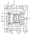
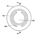
- FIG. 4 is a cross-sectional view of the discharge valve as seen from the direction of arrows IV-IV in FIG. 3.
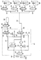
- It is an enlarged view of the VII part in FIG. It is a pneumatic circuit diagram showing an air suspension mechanism using a compressor according to a second embodiment.
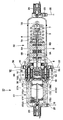
- FIG. 1 shows a first embodiment of the present invention.
- the compressor 1 is configured to include a linear motor 2, a compression unit 9 having a cylinder 10 and a piston 11, and an air dryer 17.
- the air dryer 17 side (left side in FIG. 1) of the compressor 1 is defined as one end side
- the linear motor 2 side (right side in FIG. 1) of the compressor 1 is defined as the other end side.
- the linear motor 2 is located on the other end side of the compressor 1 and is provided as a drive source for the compressor 1.
- the linear motor 2 includes a motor case 3 and a linear base 4 that constitute an outer shell of the linear motor 2, an armature 5, a mover 6, a spring 7, and the like.
- the linear motor 2 applies a current to the coil 5 ⁇ / b> B of the armature 5 to reciprocate the mover 6 in the axial direction and generate a reciprocating driving force on the piston 11.
- the motor case 3 is formed as a hollow container made of a metal material such as an aluminum material, for example, and has a bottomed cylindrical shape with one end opened and the other end closed. Inside the motor case 3, an armature 5, a mover 6, a spring 7, and the like are accommodated. A linear base 4 is engaged with the opening end side of the motor case 3 so as to close the opening. In other words, the motor case 3 is fixed to the linear base 4 with screws or the like.
- the armature 5 is fixed in the motor case 3 as a stator.
- the armature 5 includes a substantially cylindrical core 5A formed of, for example, a dust core, laminated electromagnetic steel plates, and magnetic pieces, and a plurality of coils 5B wound in a predetermined direction and housed in the core 5A. And is composed of.
- the mover 6 is located on the inner peripheral side of the armature 5 and extends along the axial direction (left and right directions in FIG. 1) of the motor case 3. That is, the mover 6 is disposed in the motor case 3 along the central axis of the linear motor 2.
- the mover 6 includes a yoke 6A formed in a flat plate shape using a magnetic material, and a plurality of permanent magnets 6B arranged in a flat plate shape on the front and back surfaces of the yoke 6A.
- the mover 6 reciprocates in the motor case 3 by applying a current to the coil 5 ⁇ / b> B of the armature 5.
- the spring 7 is located on the other side of the linear motor 2 and is provided in the motor case 3. One end of the spring 7 is fixed to one end of the armature 5 using a connector 7A, and the other end of the spring 7 is attached to the other end of the mover 6 so as to be movable in the axial direction using a connector 7B. It has been.
- the spring 7 is formed of, for example, a compression coil spring, and the mover 6 is attached toward the other end side of the compressor 1. In this case, the spring 7 expands and contracts in the axial direction as the mover 6 reciprocates.
- the suction port 8 is located at the other end of the linear motor 2 and is provided at the bottom of the motor case 3. This suction port 8 sucks air into the motor case 3 from the outside during the suction stroke of the compressor 1.
- the suction port 8 is connected to a suction conduit 25 described later.
- the compression unit 9 is provided between the linear motor 2 and the air dryer 17.
- the compression unit 9 includes a cylinder 10, a piston 11, an intake valve 12, a valve plate 13, a cylinder head 14, and a discharge valve 16. This compression part 9 drives the piston 11 by the reciprocating motion of the mover 6 of the linear motor 2 to compress the outside air and generate compressed air (working gas).
- the cylinder 10 has one end side closed by a valve plate 13 and the other end side fixed to the linear base 4.
- the cylinder 10 is formed in a cylindrical shape using, for example, an aluminum material, and a piston 11 is accommodated therein so as to be capable of reciprocating (slidable).
- the inside of the cylinder 10 is defined by a non-compression chamber 10 ⁇ / b> A communicating with the inside of the motor case 3 by the piston 11 and a compression chamber 10 ⁇ / b> B on the cylinder head 14 side.
- the piston 11 is inserted in the cylinder 10 so as to be able to reciprocate.
- the piston 11 defines a non-compression chamber 10A and a compression chamber 10B in the cylinder 10.
- the piston 11 is connected to one end side of the mover 6 of the linear motor 2 via a piston pin 11A and a coupling tool 11B. Accordingly, the piston 11 is provided along the axial direction of the linear motor 2 (motor case 3), and reciprocates in the cylinder 10 in conjunction with the reciprocating motion of the mover 6. In other words, the piston 11 is disposed on the axis of the moving direction of the mover 6 of the linear motor 2.
- the piston 11 is provided with a communication hole 11C that allows the non-compression chamber 10A and the compression chamber 10B to communicate with each other, and the intake valve 12 is screwed or caulked to the communication hole 11C.
- the intake valve 12 opens the communication hole 11C in the suction stroke of the compressor 1 to connect the non-compression chamber 10A and the compression chamber 10B, and closes the communication hole 11C in the compression stroke to compress the non-compression chamber 10A.
- the chamber 10B is shut off.
- the valve plate 13 and the cylinder head 14 are attached to one end side of the cylinder 10 so as to close one end side of the cylinder 10.
- This cylinder head 14 closes the other end side opening of the air dryer 17 by engaging with the other end side of the air dryer 17 as a discharge portion for discharging compressed air.
- a plurality of fixtures 15 are provided between the cylinder head 14 and the linear base 4 for sandwiching and fixing the cylinder 10 between the cylinder head 14 and the linear base 4.
- the discharge valve 16 is provided between the valve plate 13 and the cylinder head 14 and constitutes a reed valve that is attached to and detached from the valve seat 13A of the valve plate 13.
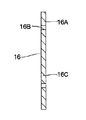
- the discharge valve 16 is made of a thin circular plate having elasticity (spring property), a base portion 16 ⁇ / b> A sandwiched between the valve plate 13 and the cylinder head 14, and a circular notch. 16B and a valve body 16C formed by the notch 16B. Since the valve body 16C is partly integrated with the base portion 16A, the valve body 16C is seated on the valve seat 13A in the suction stroke of the compressor 1 to shut off the compression chamber 10B and the air dryer 17 and in the compression stroke. The compression chamber 10B and the air dryer 17 are communicated with each other by separating from the valve seat 13A.
- the air dryer 17 is located on one end side of the compressor 1 and is provided on the opposite side of the linear motor 2 with the compression unit 9 interposed therebetween.
- the air dryers 17 are arranged in series so that the axial direction thereof is along the axial direction of the piston 11. That is, the axis of the air dryer 17 and the axis of the piston 11 extend substantially in a straight line.
- the air dryer 17 is arranged on the axis of the moving direction of the mover 6 and the piston 11 of the linear motor 2.
- the air dryer 17 includes a housing 17A, filters 17B1 and 17B2, a desiccant 17C, a spring 17D, and an exhaust pipe 17E.
- the air dryer 17 supplies compressed air (dry air) in a dry state when supplying compressed air from the compressor 1 to each air suspension 21 described later.
- the housing 17A is a hollow container made of a metal material such as an aluminum material, and is formed in a bottomed cylindrical shape with one end closed and the other end opened. The other end of the housing 17A is engaged with the cylinder head 14, thereby closing the open end of the housing 17A.
- the housing 17A is defined by filters 17B1 and 17B2, and the filters 17B1 and 17B2 are filled with a desiccant 17C.
- the filters 17B1 and 17B2 prevent part of the desiccant 17C from flowing out.
- a spring 17D is provided between the filter 17B2 and the cylinder head 14 to urge the filter 17B2 toward one end of the compressor 1 at all times.
- the exhaust pipe 17E passes through the filters 17B1 and 17B2 between the filters 17B1 and 17B2, and is provided so that one end side and the other end side of the air dryer 17 communicate with each other.
- One end side of the exhaust pipe 17E communicates with the exhaust port 19 through an exhaust valve 20 described later, and the other end side of the exhaust pipe 17E communicates with a space between the filter 17B2 and the cylinder head 14.
- the exhaust pipe 17E circulates compressed air (non-dried compressed air in which moisture is not adsorbed by the desiccant 17C) toward the exhaust port 19 in the direction of exhausting it to the outside atmosphere.
- the supply / discharge port 18 is located on one end side of the air dryer 17 and is provided on one circumferential side of the bottom of the housing 17A.
- the supply / discharge port 18 is connected to a supply / exhaust conduit 22 described later, and supplies compressed air compressed in the compression chamber 10 ⁇ / b> B toward the air suspension 21 while being dried by the air dryer 17.
- the exhausted dry compressed air is discharged into the housing 17A of the air dryer 17.
- the exhaust port 19 is located on one end side of the air dryer 17 and is provided on the other side in the circumferential direction of the bottom portion of the housing 17A.
- the exhaust port 19 is connected to an exhaust pipe 26 described later, and exhausts compressed air from the exhaust pipe 17E toward the outside.
- an exhaust valve 20 is provided between the exhaust port 19 and the exhaust pipe 17E.
- the exhaust valve 20 is a valve that allows the exhaust port 19 connected to the exhaust pipe line 26 to communicate with or cut off from the atmosphere (outside air).
- the exhaust valve 20 is configured by an ON / OFF type (open / close type) electromagnetic valve, and opens the exhaust port 19 to allow the compressed air to be discharged from the exhaust pipe 17E, and closes the exhaust port 19.
- the position is selectively switched to the closed position (b) for blocking the discharge of the compressed air from the exhaust pipe 17E. That is, the exhaust valve 20 is normally closed to block the exhaust pipe 17E from the exhaust port 19.
- the exhaust valve 20 is opened, the exhaust pipe 17E is communicated with the exhaust port 19, and the compressed air in the exhaust pipe 17E is discharged (released) into the atmosphere through the exhaust port 19 and the exhaust pipe line 26.
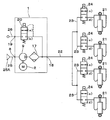
- the air suspension mechanism includes a compressor 1, an air suspension 21, a supply / exhaust conduit 22, a supply / exhaust valve 24, and the like.
- the air suspension 21 functions as an air spring between the vehicle axle side and the vehicle body side (none shown) so as to correspond to the front, rear, left, and right wheels (none shown) of the vehicle, respectively. There are four in between.
- the air suspension 21 may be provided only in front of or behind the vehicle. When compressed air is supplied or discharged, each air suspension 21 adjusts the height of the vehicle by expanding or contracting upward or downward according to the supply / discharge amount (compressed air amount) at this time. , Movably supported in the downward direction.
- These air suspensions 21 are connected to the compressor 1 via supply / exhaust pipelines 22 and branch pipelines 23.
- One end side of the supply / exhaust pipe line 22 located on the upstream side thereof is connected to the supply / exhaust port 18 of the compressor 1, and the other end side located on the downstream side thereof is connected to each branch pipe line 23.
- the supply / exhaust conduit 22 and the branch conduits 23 supply / discharge compressed air to / from the air suspensions 21.
- the supply / exhaust valve 24 is located between each air suspension 21 and the compressor 1 and is provided in the middle of each branch pipe 23.
- the air supply / exhaust valve 24 is configured by an ON / OFF type electromagnetic valve in substantially the same manner as the exhaust valve 20, and an open position (c) that allows each air suspension 21 to supply and discharge compressed air by opening each branch pipe 23. ) And a closed position (d) in which each branch pipe 23 is closed and supply / discharge of compressed air to / from each air suspension 21 is shut off.
- the suction pipe 25 is connected to the suction port 8 of the compressor 1.
- the suction pipe 25 is always in communication with the atmosphere, and allows the air sucked from the intake filter 25A to flow into the compressor 1.
- the exhaust pipe 26 is connected to the exhaust port 19 of the compressor 1. This exhaust pipe 26 is always in communication with the atmosphere, and when the exhaust valve 20 is opened, it communicates with the exhaust pipe 17E through the exhaust port 19, and the compressed air in the exhaust pipe 17E is discharged (released) into the atmosphere. To do.
- the compressor 1 according to the first embodiment has the above-described configuration, and the operation thereof will be described next.
- the permanent magnet 6 ⁇ / b> B of the mover 6 receives thrust in the axial direction and slides the entire mover 6 toward one end side of the compressor 1. .
- the movable element 6 slides toward the other end side of the compressor 1 by the urging force of the spring 7 by reversing the direction of the current.
- the thrust of the reciprocating motion of the mover 6 is transmitted to the piston 11 via the connector 11B.
- the piston 11 reciprocates in the cylinder 10, and alternately repeats a suction stroke in which the piston 11 moves away from the cylinder head 14 and a compression stroke in which the piston 11 approaches the cylinder head 14.
- the air supply / exhaust valve 24 is switched from the closed position (d) to the open position (c).
- the compressed air is supplied to each air suspension 21 via the supply / discharge line 22 and the branch line 23.
- the air supply / exhaust valve 24 is switched to the closed position (d) to close the branch pipe 23.
- the air supply / exhaust valve 24 is switched to the open position (c) and the exhaust valve 20 is switched from the closed position (b) to the open position (a).
- the compressed air in each air suspension 21 is led out into the compressor 1 through the branch line 23 and the supply / discharge line 22.
- the compressed air that has flowed into the compressor 1 through the supply / discharge port 18 flows back in the air dryer 17 to take away moisture adsorbed by the desiccant 17C, and regenerates the desiccant 17C.
- the compressed air is discharged (released) to the outside through the exhaust pipe 17E, the exhaust valve 20, the exhaust port 19, and the exhaust pipe 26.
- the compressed air is discharged from each air suspension 21, and each air suspension 21 shifts to a contracted state, whereby the vehicle height can be lowered.
- the compressor 1 is configured, for example, in a straight line such that the axis of the linear motor 2, the axis of the piston 11, and the axis of the air dryer 17 are along each other. .
- the air dryer 17 is arranged on the axes of the moving direction of the mover 6 of the linear motor 2 and the moving direction of the piston 11.
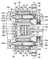
- FIGS. 6 to 8 show a second embodiment of the present invention.
- the feature of the second embodiment resides in that the compressor is used in a closed type air suspension mechanism.
- the same components as those in the first embodiment are denoted by the same reference numerals, and the description thereof is omitted.
- the compressor 31 includes a linear motor 32, a compression unit 35, an air dryer 37, a storage switching valve 38, and a supply / discharge switching valve 48.
- the linear motor 32 is located on the other end side of the compressor 31 and is provided as a drive source for the compressor 31.
- the linear motor 32 includes a motor case 3, a linear base 4, an armature 5, a mover 6, a spring 7, and the like, almost similar to the linear motor 2 of the first embodiment. Further, on the other end side of the linear motor 32, a suction port 33 and an intake valve 34 are provided for sucking air into the motor case 3 from the outside during the suction stroke of the compressor 31.
- the linear base 4 is additionally provided with a first bypass passage 47 and a second bypass passage 57 which will be described later.
- These bypass passages 47, 57 and the like are not necessarily provided integrally with the linear base 4, and may be configured by separate members.
- the suction port 33 is located on the other end side of the linear motor 2 and is provided at the bottom of the motor case 3.
- One end side of the suction port 33 communicates with the inside of the motor case 3 via the intake valve 34, and the suction line 25 is connected to the other end side of the suction port 33.
- the intake valve 34 is provided between the suction port 33 and the motor case 3 as a suction valve for sucking outside air.
- the intake valve 34 is arranged such that its axial direction is along the axial direction of the piston 11.
- the intake valve 34 is a valve that allows the suction port 33 to communicate with and shut off from the outside air.
- the intake valve 34 is configured by an ON / OFF type electromagnetic valve substantially similar to the exhaust valve 20, and has an open position (e) that allows the compressor 31 to suck gas by opening the suction port 33, and the suction port 33. It is selectively switched to a closed position (f) that closes and blocks the suction of gas by the compressor 31. That is, the intake valve 34 is normally closed to block the inside of the motor case 3 of the compressor 31 from the outside air.
- the intake valve 34 is opened, the inside of the motor case 3 is communicated with the outside air, and the air sucked from the intake filter 25A is caused to flow into the compressor 31.
- the compression unit 35 is provided between the linear motor 32 and the air dryer 37.
- the compression unit 35 includes a cylinder 10, a piston 11, an intake valve 12, a valve plate 13, a discharge valve 16, and a cylinder head 36 in substantially the same manner as the compression unit 9 of the first embodiment. It is configured.
- the cylinder head 36 is attached to one end side of the cylinder 10 so as to close one end side of the cylinder 10.
- the cylinder head 36 closes the other end side opening of the air dryer 37 by engaging with the other end side of the air dryer 37 as a discharge portion for discharging compressed air.
- the cylinder head 36 is formed with mounting holes 36 ⁇ / b> A and 36 ⁇ / b> B that are spaced apart in the circumferential direction and extend in parallel with each other so as to penetrate one end side and the other end side in the axial direction of the cylinder head 36.
- a core 43 of a later-described storage switching valve 38 is mounted in the mounting hole 36A, and a core 53 of a later-described supply / discharge switching valve 48 is mounted in the mounting hole 36B.
- the air dryer 37 is located on one end side of the compressor 31 and is provided on the opposite side of the linear motor 32 with the compression unit 35 interposed therebetween.
- the air dryers 37 are arranged in series so that the axial direction thereof is along the axial direction of the piston 11. That is, the axis of the air dryer 37 and the axis of the piston 11 extend substantially in a straight line.
- the air dryer 37 includes a housing 37A, filters 17B1 and 17B2, a desiccant 17C, a spring 17D, and an exhaust pipe 17E in substantially the same manner as the air dryer 17 of the first embodiment. .
- the air dryer 37 in this case is different from the air dryer 17 of the first embodiment in that the housing 37A has a double cylinder structure including the outer cylinder 37A1 and the inner cylinder 37A2.
- the housing 37A is formed as a hollow container made of a metal material such as an aluminum material, and has a bottomed cylindrical shape with one end closed and the other end opened. The other end of the housing 37A is engaged with the cylinder head 36, thereby closing the open end of the housing 37A.
- the housing 37A includes an outer cylinder 37A1 that forms an outer shell of the housing 37A, and an inner cylinder 37A2 that is provided coaxially with the outer cylinder 37A1. Between this outer cylinder 37A1 and inner cylinder 37A2, it is the cyclic
- the exhaust port 19 and the exhaust valve 20 are provided at the bottom of the outer cylinder 37A1 as in the first embodiment.
- the supply / discharge port 18 described in the first embodiment is not provided on the bottom side of the outer cylinder 37A1, and the annular passage 37A3 forms the supply / discharge port.
- the inner cylinder 37A2 is defined by filters 17B1 and 17B2, and the filters 17B1 and 17B2 are filled with a desiccant 17C.
- the storage switching valve 38 is provided between the cylinder head 36 and the linear base 4 as a first electromagnetic valve, located on the outer peripheral side (outside in the radial direction of the cylinder 10) of the compression unit 35.
- the axis of the storage switching valve 38 is arranged in parallel so as to be along the axis of the piston 11.
- the storage switching valve 38 is arranged in parallel with the movement direction of the piston 11 or the movement direction of the piston 11 and the operation direction of the storage switching valve 38 are the same direction.
- the storage switching valve 38 drives a later-described valve body 42 to selectively communicate and block the tank supply / exhaust port 46 with either the air passage 43A on the core 43 side or the first bypass passage 47 described later. .
- the storage switching valve 38 is formed as a covered cylindrical body and is provided with a valve case 39 provided between the linear base 4 and the cylinder head 36, and inside the valve case 39. And a valve holding cylinder 40 in which the valve seat portion 40A on the front end side is airtightly fitted to the first bypass passage 47 side, and is positioned between the valve holding cylinder 40 and the valve cylinder case 39.
- the coil 41 is wound around the outer periphery of the holding cylinder 40, and includes a valve body 42 and a core 43 described later.
- the valve body 42 of the storage switching valve 38 is disposed in the valve holding cylinder 40 so as to face the core 43.
- the valve element 42 is positioned between the valve seat 40A of the valve holding cylinder 40 and the core 43 and is slidably fitted into the valve holding cylinder 40.
- a first valve portion 42A that separates from and seats on the seat portion 40A is provided.
- a valve spring 44 is disposed between the valve body 42 and the core 43, and the valve spring 44 constantly urges the valve body 42 toward the valve seat 40 ⁇ / b> A side of the valve holding cylinder 40. .
- a small-diameter air passage 43A is formed in the axial direction on the center side of the core 43, and a second valve portion 42B that opens and closes the air passage 43A on the proximal end side of the valve body 42 that faces the core 43 in the axial direction.
- the air passage 43A forms a passage connecting the air dryer 37 and a tank 58 described later.
- an inner passage portion 45 is formed which is located between the valve holding cylinder 40 and extends in the axial direction of the valve body 42.
- the tank supply / exhaust port 46 (replenishment pipeline 59) is always in communication with the outer peripheral side of the first valve portion 42A.
- one side (upstream side) of the inner passage portion 45 is communicated with or blocked from the air passage 43A on the core 43 side by opening and closing the second valve portion 42B. Further, the other side (downstream side) of the inner passage portion 45 is opened and closed with respect to the first bypass passage 47 when the first valve portion 42A is seated on the valve seat portion 40A of the valve holding cylinder 40 to open and close. Communicated and blocked. As a result, the inner passage portion 45, the tank supply / exhaust port 46, and the supply conduit 59 are selectively communicated and blocked with either the air passage 43 ⁇ / b> A on the core 43 side or the first bypass passage 47.
- the air passage 43A of the core 43 is always in communication with an annular passage 37A3 formed between the outer cylinder 37A1 and the inner cylinder 37A2 of the air dryer 37.
- the compressed air dried in the air dryer 37 is circulated (supplied) to the air passage 43 ⁇ / b> A of the core 43.
- the storage switching valve 38 selectively connects, for example, the suction side (that is, the first bypass passage 47) or the discharge side (air passage 43A) of the compressor 31 to a tank 58 described later. It is comprised by the electromagnetic direction switching valve. That is, the storage switching valve 38 has a supply / discharge position (g) for supplying and discharging compressed air to and from the tank 58 through the tank supply / exhaust port 46 and a supply pipe 59 described later, and the compressed air in the tank 58 to the first bypass passage 47. Is selectively switched to a switching position (h) to be supplied to the suction side of the compressor 31.
- the tank supply / discharge port 46 is located on the outer peripheral side of the compression unit 35 and is provided on the other end side of the storage switching valve 38. One side of the tank supply / discharge port 46 is connected to a storage switching valve 38, and the other side of the tank supply / discharge port 46 is connected to a supply line 59.
- the tank supply / discharge port 46 supplies the compressed air compressed in the compression chamber 10B and dried by the air dryer 37 to the tank 58, or the compressed air exhausted from the tank 58 passes through the storage switching valve 38 and the annular passage 37A3. Or a discharge / discharge switching valve 48 described later.
- the first bypass passage 47 is located in the linear base 4 and is provided on the other end side of the storage switching valve 38. One side of the first bypass passage 47 is connected to the storage switching valve 38, and the other side of the first bypass passage 47 is connected to the non-compression chamber 10A (linear base 4).
- the first bypass passage 47 allows compressed air in the tank 58 to flow toward the non-compression chamber 10A when the storage switching valve 38 is switched to the switching position (h).
- the first bypass passage 47 is provided with a check valve 47A for preventing the backflow of compressed air.
- the check valve 47 ⁇ / b> A constitutes an intake valve that forms a parallel relationship with the intake valve 34.
- the supply / discharge switching valve 48 is provided between the cylinder head 36 and the linear base 4 as a second electromagnetic valve, located on the outer peripheral side (outside in the radial direction of the cylinder 10) of the compression unit 35.
- the supply / discharge switching valve 48 is provided at a different position from the storage switching valve 38 so as to extend in parallel with each other on the outer peripheral side of the compression section 35.
- the axis of the supply / discharge switching valve 48 is arranged in parallel so as to be along the axis of the piston 11. In other words, the supply / discharge switching valve 48 is arranged in parallel to the movement direction of the piston 11 or so that the movement direction of the piston 11 and the operation direction of the supply / discharge switching valve 48 are the same direction.
- the supply / discharge switching valve 48 drives a later-described valve body 52 to selectively communicate or block the air suspension supply / discharge port 56 with either the air passage 53A on the core 53 side or the second bypass passage 57. .
- the supply / discharge switching valve 48 includes a valve case 49 formed between the linear base 4 and the cylinder head 36, which is formed as a covered cylindrical body, and the valve case substantially similar to the storage switching valve 38. 49, a valve holding cylinder 50 in which a valve seat portion 50A on the front end side is airtightly fitted to a second bypass passage 57 described later, and between the valve holding cylinder 50 and the valve case 49 And a coil 51 wound around the outer periphery of the valve holding cylinder 50, a valve body 52 and a core 53, which will be described later.
- the valve body 52 of the supply / discharge switching valve 48 is disposed in the valve holding cylinder 50 so as to face the core 53. As shown in FIG. 7, the valve body 52 is positioned between the valve seat portion 50A of the valve holding cylinder 50 and the core 53, and is slidably fitted into the valve holding cylinder 50. A first valve portion 52A is provided to be seated on and off the seat portion 50A. A valve spring 54 is disposed between the valve body 52 and the core 53, and the valve spring 54 constantly urges the valve body 52 toward the valve seat portion 50 ⁇ / b> A of the valve holding cylinder 50. .
- a small-diameter air passage 53A is bored in the axial direction on the center side of the core 53, and a second valve portion 52B that opens and closes the air passage 53A on the proximal end side of the valve body 52 that faces the core 53 in the axial direction.
- the air passage 53 ⁇ / b> A forms an air spring passage that connects the air dryer 37 and the air suspension 21.
- an inner passage portion 55 is formed, which is located between the valve holding cylinder 50 and extends in the axial direction of the valve body 52.
- the air suspension supply / exhaust port 56 (supply / discharge conduit 22) is always in communication with the outer peripheral side of the first valve portion 52A.
- one side (upstream side) of the inner passage portion 55 is communicated with or blocked from the air passage 53A on the core 53 side by opening and closing the second valve portion 52B. Further, the other side (downstream side) of the inner passage portion 55 is opened and closed by the first valve portion 52A being separated from and seated on the valve seat portion 50A of the valve holding cylinder 50, whereby a second bypass passage 57 described later. Is communicated and blocked.
- the inner passage portion 55, the air suspension supply / exhaust port 56, and the supply / exhaust conduit 22 are selectively communicated and blocked with either the air passage 53 ⁇ / b> A on the core 53 side or the second bypass passage 57.
- the air passage 53A of the core 53 is always in communication with an annular passage 37A3 formed between the outer cylinder 37A1 and the inner cylinder 37A2 of the air dryer 37.
- the compressed air dried in the air dryer 37 is circulated (supplied) through the air passage 53 ⁇ / b> A of the core 53.
- the supply / discharge switching valve 48 selectively connects, for example, the suction side (that is, the second bypass passage 57) or the discharge side (vent passage 53A) of the compressor 31 to the air suspension 21. It is comprised by the electromagnetic direction switching valve. That is, the supply / discharge switching valve 48 is configured to supply / discharge the compressed air to / from each air suspension 21 through the air suspension supply / discharge port 56, the supply / exhaust conduit 22 and the branch conduit 23, and each air suspension 21. The compressed air is selectively switched to a switching position (j) for supplying the compressed air inside to the suction side of the compressor 31 through a second bypass passage 57 described later.
- the air suspension supply / discharge port 56 is located on the outer peripheral side of the compression unit 35 and is provided on the other end side of the supply / discharge switching valve 48. One side of the air suspension supply / discharge port 56 is connected to the supply / discharge switching valve 48, and the other side of the air suspension supply / discharge port 56 is connected to the supply / discharge line 22.
- the air suspension supply / exhaust port 56 supplies compressed air compressed in the compression chamber 10B toward each air suspension 21, or discharges compressed air exhausted from each air suspension 21 to the outside via the exhaust pipe 17E. To do.
- the second bypass passage 57 is located in the linear base 4 and is provided on the other end side of the supply / discharge switching valve 48. One side of the second bypass passage 57 is connected to the supply / discharge switching valve 48, and the other side of the second bypass passage 57 is connected to the non-compression chamber 10A (linear base 4).
- the second bypass passage 57 allows the compressed air in each air suspension 21 to flow toward the non-compression chamber 10A when the supply / discharge switching valve 48 is switched to the switching position (j).
- the second bypass passage 57 is provided with a check valve 57A for preventing the backflow of compressed air.
- the check valve 57 ⁇ / b> A constitutes an intake valve that forms a parallel relationship with the intake valve 34.
- This air suspension mechanism includes a compressor 31, an air suspension 21, a supply / exhaust conduit 22, a supply / exhaust valve 24, a tank 58, a supply conduit 59, and the like.
- the tank 58 stores compressed air that has been pressurized from the air dryer 37 of the compressor 31 and has been pressurized beyond the atmospheric pressure.
- the tank 58 and the compressor 31 are connected to each other through a supply line 59 described later, and the compressed air discharged from the compressor 31 is stored in the tank 58 through the supply line 59.
- the compressed air stored in the tank 58 (or compressed air discharged from the compressor 31) is supplied to each air suspension 21 through the supply / exhaust conduit 22 and the branch conduit 23.
- the supply line 59 is a line for connecting the tank supply / exhaust port 46 and the tank 58 to supply the tank 58 with compressed air.
- a tank valve 60 for switching supply / exhaust of compressed air to / from the tank 58 is provided in the supply line 59.
- the tank valve 60 is provided in the replenishment pipeline 59 and is constituted by, for example, an ON / OFF type electromagnetic valve.
- the tank valve 60 has an open position (k) in which the supply pipe 59 is opened to allow supply and discharge of compressed air to the tank 58, and a closed position in which the supply pipe 59 is closed to block supply and discharge of compressed air to the tank 58 ( l).
- the pressure sensor 61 is located between the storage switching valve 38 and the air dryer 37 and is provided in the middle of the air passage 43 ⁇ / b> A.
- the pressure sensor 61 detects the pressure of the compressed air in the tank 58 by detecting the pressure in the air passage 43A.
- the compressor 31 according to the second embodiment has the above-described configuration, and the operation thereof will be described next.
- the tank valve 60 and the intake valve 34 are closed (l).
- (F) are switched to the open positions (k), (e), and the storage switching valve 38 is moved to the supply / discharge position (with the exhaust valve 20 and the supply / exhaust valve 24 held at the closed positions (b), (d).
- the compressor 31 is operated (that is, compression operation).
- the compression unit 35 of the compressor 31 sucks outside air through the intake filter 25A and the suction pipe 25, pressurizes (compresses) the air, and discharges the air toward the air dryer 37.
- the compressed air is dried by the air dryer 37 and then stored in the tank 58 via the passage 37A3, the air passage 43A, the tank supply / discharge port 46, the supply conduit 59, and the tank valve 60 in the housing 37A.
- the linear motor 32 that is, the compressor 31
- the tank valve 60 and the intake valve 34 are both closed (l), (f). Switch.
- the tank 58 can be filled with a sufficient amount of compressed air and stored.
- the compressed air in the tank 58 can be supplied to each air suspension 21 even when the compressor 31 is stopped. That is, in this case, the tank valve 60 is switched from the closed position (l) to the open position (k), and the storage switching valve 38 and the supply / discharge switching valve 48 are held at the supply / discharge positions (g), (i). Thus, the air supply / exhaust valve 24 is switched to the open position (c). As a result, the compressed air in the tank 58 is led out to the supply / exhaust conduit 22, and this compressed air is supplied into each air suspension 21 through the branch conduit 23. As described above, the compressed air stored in the tank 58 can be supplied into the air suspensions 21 and the air suspensions 21 can be quickly expanded. For example, the compressed air generated by the compressor 31 can be directly generated. The vehicle height can be quickly increased as compared with the case where the air suspension 21 is supplied.
- the compressed air in the tank 58 can be further compressed by the compressor 31 by the reciprocating motion of the piston 11 in the cylinder 10, and the compressed air at a high pressure is supplied to each air suspension via the air dryer 37, the supply / discharge switching valve 48 and the like. 21 can be supplied.
- the supply / exhaust valve 24 is switched to the closed position (d) and the branch line 23 is closed. Thereby, the flow of the compressed air to each air suspension 21 is prevented, and each air suspension 21 can be kept in the extended state and the vehicle height can be kept high.
- the tank valve 60 and the supply / exhaust valve 24 are switched to the open positions (k), (c), the storage switching valve 38 is held at the supply / discharge position (g), 48 is switched from the supply / discharge position (i) to the switching position (j).
- the compressor 31 starts to be moved by the linear motor 32, the compressed air in each air suspension 21 is discharged (derived) to the second bypass passage 57 through the branch conduit 23 and the supply / discharge conduit 22. Then, the compressed air led out to the second bypass passage 57 flows into the motor case 3.
- the compressed air (exhaust gas from the air suspension 21) may be recompressed by the compressor 31 and discharged toward the tank 58. Further, the compressed air may be simply circulated from the motor case 3 toward the tank 58 without substantially compressing the compressed air. That is, the operating state of the compressor 31 is determined by the pressure difference between the tank 58 and the air suspension 21.
- the compressed air discharged (or outflowed) from the compression chamber 10 ⁇ / b> B of the compression unit 35 is replenished into the tank 58 through the air dryer 37, the air passage 43 ⁇ / b> A, and the replenishment conduit 59.
- the compressed air is discharged from each air suspension 21, and each air suspension 21 shifts to a contracted state, whereby the vehicle height can be lowered.
- the tank valve 60 is returned to the closed position (l) based on a detection signal from the pressure sensor 61, for example. Then, the supply / discharge switching valve 48 is switched from the switching position (j) to the supply / discharge position (i), and the exhaust valve 20 is switched from the closed position (b) to the open position (a).
- the compressed air from each air suspension 21 is directly discharged from the exhaust pipe 26 to the outside via the branch pipe 23, the supply / discharge pipe 22, the ventilation path 53 ⁇ / b> A, the exhaust pipe 17 ⁇ / b> E, and the exhaust port 19. be able to.
- the storage switching valve 38 is located on the outer peripheral side of the compression unit 35 and is arranged in parallel so that the axis of the storage switching valve 38 is along the axis of the piston 11. Thereby, the storage switching valve 38 can be placed close to the compression unit 35 and compactly arranged. As a result, the compressor 31 can be reduced in the radial direction, so that the degree of freedom in layout design can be increased, space saving can be achieved, and the vehicle mountability of the compressor 31 can be improved.
- the supply / discharge switching valve 48 is positioned on the outer peripheral side of the compression section 35 and is arranged in parallel so that the axis of the supply / discharge switching valve 48 is along the axis of the piston 11. Thereby, the supply / discharge switching valve 48 can be placed close to the compression unit 35 and compactly arranged. As a result, the compressor 31 can be reduced in the radial direction, so that the degree of freedom in layout design can be increased, space saving can be achieved, and the vehicle mountability of the compressor 31 can be improved.
- the intake valve 34 is arranged so that its axial direction is along the axial direction of the piston 11.
- the linear motor 32, the compression part 35, the air dryer 37, and the intake valve 34 can be provided in series in the axial direction of the compressor 1, it is possible to reduce the size of the compressor 31 in the radial direction. 31 can be thinned to a linear shape. As a result, downsizing of the compressor 31 increases the degree of freedom in layout design and saves space, so that the vehicle mountability of the compressor 31 can be improved.
- the compressor 1 is used in an open type air suspension mechanism that sucks and exhausts outside air that does not use a tank.
- the present invention is not limited to this.
- the compressor may be used in a closed type air suspension mechanism. It can be applied to an open type tank.
- the motor case 3 of the linear motor 2 and the housing 17A of the air dryer 17 are formed in a cylindrical shape.
- the present invention is not limited to this.
- the motor case and the housing may be formed in a shape other than a cylindrical shape. This is the same for the second embodiment.
- the central axis of the linear motor 2, the central axis of the compression unit 9, and the central axis of the air dryer 17 are arranged so as to coincide with each other.
- the present invention is not limited to this, and does not exclude, for example, an arrangement in which the central axis of the compression unit and the central axis of the air dryer are slightly offset with respect to the central axis of the linear motor.
- the center axis of the linear motor and the center axis of the air dryer may be offset with respect to the center axis of the compression unit, or the center axis of the linear motor and the center axis of the compression unit may be offset from the center axis of the air dryer. May be offset. This is the same for the second embodiment.
- the pressure sensor 61 is provided in the ventilation path 43A.
- the present invention is not limited to this.
- the pressure sensor may be provided in the tank, or may be provided in other locations.
- the compressors 1 and 31 are mounted on a vehicle such as a four-wheeled vehicle.
- the present invention is not limited to this.
- the compressor may be applied to a compressor that drives pneumatic equipment such as an air cylinder.
- the present invention has a passage connecting an air dryer and a tank for storing a working gas discharged from the air dryer, and a first electromagnetic valve provided in the passage, and the first electromagnetic valve is a compressor portion. It is the outer peripheral side, Comprising: It is set as the structure arrange
- the present invention also includes an air spring passage that branches the passage and connects an air dryer and an air spring that supports the vehicle body so as to be movable upward and downward, and a second electromagnetic valve provided in the air spring passage.
- the 2nd solenoid valve is the outer peripheral side of a compression part, Comprising: It is set as the structure arrange
- a suction valve for sucking outside air is arranged on the other end side of the linear motor so that its axis is along the axis of the piston.
- a linear motor having a reciprocating mover, a piston reciprocatingly connected to the mover on one end side of the linear motor, and a slidably accommodated piston.
- a compression section having a compression chamber, and an air dryer connected to a discharge section of the compression chamber of the compression section and filled with a desiccant therein. It arrange
- a passage connecting the air dryer and a tank storing the working gas discharged from the air dryer, and a first electromagnetic valve provided in the passage.
- the first electromagnetic valve is disposed on the outer peripheral side of the compression portion so that the moving direction of the piston and the operating direction of the first electromagnetic valve are the same direction.
- an air spring passage that branches the passage and connects the air dryer and an air spring that supports the vehicle body so as to be movable upward and downward, and the air
- a second electromagnetic valve provided in a spring passage, wherein the second electromagnetic valve is on an outer peripheral side of the compression portion, and the moving direction of the piston and the operating direction of the second electromagnetic valve are the same direction. It is arranged to become.
- a suction valve for sucking outside air is provided on the other end side of the linear motor, and a moving direction of the piston and an operation of the suction valve. Arrange them in the same direction.
Landscapes
- Engineering & Computer Science (AREA)
- Mechanical Engineering (AREA)
- General Engineering & Computer Science (AREA)
- Vehicle Body Suspensions (AREA)
- Compressor (AREA)
- Compressors, Vaccum Pumps And Other Relevant Systems (AREA)
Abstract
Description
圧縮機の第1の態様としては、往復動する可動子を有するリニアモータと、該リニアモータの一端側で前記可動子に接続されて往復動するピストンと、該ピストンを摺動可能に収容し圧縮室を形成するシリンダと、を有する圧縮部と、前記圧縮部の前記圧縮室の吐出部に接続され内部に乾燥剤が充填されたエアドライヤと、からなり、該エアドライヤは、前記可動子および前記ピストンの移動方向の軸線上に配置される。
圧縮機の第2の態様としては、第1の態様において、前記エアドライヤと、該エアドライヤが吐出する作動気体を貯留するタンクとを繋ぐ通路と、該通路に設けられる第1電磁弁と、を有し、前記第1電磁弁は、前記圧縮部の外周側であって、前記ピストンの移動方向と前記第1電磁弁の動作方向が同方向となるように配置される。
圧縮機の第3の態様としては、上記第2の態様において、前記通路を分岐して前記エアドライヤと車体を上,下方向に移動可能に支持するエアスプリングとを繋ぐエアスプリング通路と、該エアスプリング通路に設けられる第2電磁弁と、を有し、前記第2電磁弁は、前記圧縮部の外周側であって、前記ピストンの移動方向と前記第2電磁弁の動作方向が同方向となるように配置される。
圧縮機の第4の態様としては、上記第1~第3の態様のいずれかにおいて、前記リニアモータの他端側には、外気を吸込む吸込み弁を前記ピストンの移動方向と前記吸込み弁の動作方向が同方向となるように配置する。
2,32 リニアモータ
6 可動子
9,35 圧縮部
10 シリンダ
10B 圧縮室
11 ピストン
12 吸気弁
14,36 シリンダヘッド(吐出部)
17,37 エアドライヤ
17C 乾燥剤
21 エアサスペンション(エアスプリング)
34 吸気バルブ(吸込み弁)
38 貯留切換バルブ(第1電磁弁)
43A 通気路(タンク通路)
48 給排切換バルブ(第2電磁弁)
53A 通気路(エアスプリング通路)
58 タンク
Claims (4)
- 往復動する可動子を有するリニアモータと、
該リニアモータの一端側で前記可動子に接続されて往復動するピストンと、該ピストンを摺動可能に収容し圧縮室を形成するシリンダと、を有する圧縮部と、
前記圧縮部の前記圧縮室の吐出部に接続され内部に乾燥剤が充填されたエアドライヤと、からなり、
該エアドライヤは、前記可動子および前記ピストンの移動方向の軸線上に配置される圧縮機。 - 前記エアドライヤと、該エアドライヤが吐出する作動気体を貯留するタンクとを繋ぐ通路と、該通路に設けられる第1電磁弁と、を有し、
前記第1電磁弁は、前記圧縮部の外周側であって、前記ピストンの移動方向と前記第1電磁弁の動作方向が同方向となるように配置されることを特徴とする請求項1に記載の圧縮機。 - 前記通路を分岐して前記エアドライヤと車体を上,下方向に移動可能に支持するエアスプリングとを繋ぐエアスプリング通路と、該エアスプリング通路に設けられる第2電磁弁と、を有し、
前記第2電磁弁は、前記圧縮部の外周側であって、前記ピストンの移動方向と前記第2電磁弁の動作方向が同方向となるように配置されることを特徴とする請求項2に記載の圧縮機。 - 前記リニアモータの他端側には、外気を吸込む吸込み弁を前記ピストンの移動方向と前記吸込み弁の動作方向が同方向となるように配置することを特徴とする請求項1ないし3のいずれかに記載の圧縮機。
Priority Applications (5)
| Application Number | Priority Date | Filing Date | Title |
|---|---|---|---|
| US16/064,516 US11319943B2 (en) | 2015-12-24 | 2016-12-14 | Compressor |
| JP2017558060A JP6630366B2 (ja) | 2015-12-24 | 2016-12-14 | 圧縮機 |
| KR1020187016285A KR102062477B1 (ko) | 2015-12-24 | 2016-12-14 | 압축기 |
| CN201680074860.7A CN108431415B (zh) | 2015-12-24 | 2016-12-14 | 压缩机 |
| DE112016005979.5T DE112016005979B4 (de) | 2015-12-24 | 2016-12-14 | Kompressor |
Applications Claiming Priority (2)
| Application Number | Priority Date | Filing Date | Title |
|---|---|---|---|
| JP2015-251840 | 2015-12-24 | ||
| JP2015251840 | 2015-12-24 |
Publications (1)
| Publication Number | Publication Date |
|---|---|
| WO2017110624A1 true WO2017110624A1 (ja) | 2017-06-29 |
Family
ID=59090266
Family Applications (1)
| Application Number | Title | Priority Date | Filing Date |
|---|---|---|---|
| PCT/JP2016/087246 Ceased WO2017110624A1 (ja) | 2015-12-24 | 2016-12-14 | 圧縮機 |
Country Status (6)
| Country | Link |
|---|---|
| US (1) | US11319943B2 (ja) |
| JP (1) | JP6630366B2 (ja) |
| KR (1) | KR102062477B1 (ja) |
| CN (1) | CN108431415B (ja) |
| DE (1) | DE112016005979B4 (ja) |
| WO (1) | WO2017110624A1 (ja) |
Cited By (1)
| Publication number | Priority date | Publication date | Assignee | Title |
|---|---|---|---|---|
| WO2020066626A1 (ja) * | 2018-09-25 | 2020-04-02 | 日立オートモティブシステムズ株式会社 | コンプレッサ装置 |
Families Citing this family (7)
| Publication number | Priority date | Publication date | Assignee | Title |
|---|---|---|---|---|
| US11433730B2 (en) * | 2018-09-25 | 2022-09-06 | Hitachi Astemo, Ltd. | Air suspension apparatus |
| US11135888B2 (en) * | 2019-02-26 | 2021-10-05 | Beijingwest Industries Co., Ltd. | Closed integrated air management module |
| CN110594125B (zh) * | 2019-09-27 | 2020-12-11 | 中国科学院理化技术研究所 | 一种线性压缩机 |
| DE102022104828A1 (de) * | 2022-03-01 | 2023-09-07 | Zf Cv Systems Europe Bv | Verfahren zum Betreiben eines Pneumatiksystems und Pneumatiksystem mit Druckluftversorgungsanlage und Luftfederanlage |
| KR102714497B1 (ko) * | 2022-07-25 | 2024-10-07 | 현대자동차주식회사 | 차량용 센서의 세정 건조를 위한 압축 공기의 공급 액츄에이터 |
| US12276269B2 (en) * | 2023-03-19 | 2025-04-15 | Weidong Lu | Integrated air supply unit |
| DE102023126031A1 (de) * | 2023-09-26 | 2025-03-27 | Zf Cv Systems Global Gmbh | Scrollverdichter-Anordnung |
Citations (3)
| Publication number | Priority date | Publication date | Assignee | Title |
|---|---|---|---|---|
| JPH03158732A (ja) * | 1989-11-15 | 1991-07-08 | Tokico Ltd | コンプレッサ、エアドライヤ組立体のエア洩れ検査方法およびエアドライヤ |
| JP2002252959A (ja) * | 2001-02-23 | 2002-09-06 | Matsushita Electric Ind Co Ltd | リニア圧縮機及びその制御装置 |
| JP2011074842A (ja) * | 2009-09-30 | 2011-04-14 | Hitachi Automotive Systems Ltd | 圧縮空気給排装置 |
Family Cites Families (15)
| Publication number | Priority date | Publication date | Assignee | Title |
|---|---|---|---|---|
| JPH03245814A (ja) * | 1990-02-21 | 1991-11-01 | Mitsubishi Electric Corp | ドライヤ |
| DE4343733A1 (de) * | 1993-12-21 | 1995-06-22 | Roediger Anlagenbau | Steueranordnung für ein durch Unterdruck betätigbares Absperrventil |
| CN2256946Y (zh) * | 1995-12-05 | 1997-06-25 | 李胜 | 直线往复压缩机 |
| US5733108A (en) * | 1996-05-28 | 1998-03-31 | White Consolidated Industries, Inc. | Hermetic refrigeration compressor |
| JP4019336B2 (ja) * | 1998-03-18 | 2007-12-12 | 株式会社日立製作所 | エアコンプレッサ |
| US6273688B1 (en) | 1998-10-13 | 2001-08-14 | Matsushita Electric Industrial Co., Ltd. | Linear compressor |
| US6640780B2 (en) * | 2000-11-15 | 2003-11-04 | Xrdi, Inc. | Side valve arrangement for an internal combustion engine |
| JP4035044B2 (ja) | 2002-12-24 | 2008-01-16 | アイシン精機株式会社 | 空気圧縮機 |
| JP4423977B2 (ja) | 2003-01-31 | 2010-03-03 | アイシン精機株式会社 | 車両用コンプレッサ装置 |
| US20040173518A1 (en) * | 2003-03-03 | 2004-09-09 | Yuan Kuang Cheung | Coaxial filter and pump |
| KR100565485B1 (ko) * | 2003-06-04 | 2006-03-30 | 엘지전자 주식회사 | 리니어 압축기 |
| DE102010054704A1 (de) * | 2010-12-16 | 2012-06-21 | Wabco Gmbh | Druckluftversorgungsanlage und pneumatisches System |
| CN202182010U (zh) * | 2011-08-03 | 2012-04-04 | 中国电子科技集团公司第十六研究所 | 一种用于线性压缩机的轴向吸排气阀 |
| DE102012005308B4 (de) * | 2011-12-23 | 2022-03-17 | Wabco Gmbh | Druckluftversorgungsanlage, Druckluftversorgungssystem und Fahrzeug, insbesondere PKW, mit einer Druckluftversorgungsanlage |
| JP6167878B2 (ja) * | 2013-11-29 | 2017-07-26 | アイシン精機株式会社 | 車高調整装置 |
-
2016
- 2016-12-14 CN CN201680074860.7A patent/CN108431415B/zh active Active
- 2016-12-14 US US16/064,516 patent/US11319943B2/en active Active
- 2016-12-14 WO PCT/JP2016/087246 patent/WO2017110624A1/ja not_active Ceased
- 2016-12-14 JP JP2017558060A patent/JP6630366B2/ja active Active
- 2016-12-14 KR KR1020187016285A patent/KR102062477B1/ko active Active
- 2016-12-14 DE DE112016005979.5T patent/DE112016005979B4/de active Active
Patent Citations (3)
| Publication number | Priority date | Publication date | Assignee | Title |
|---|---|---|---|---|
| JPH03158732A (ja) * | 1989-11-15 | 1991-07-08 | Tokico Ltd | コンプレッサ、エアドライヤ組立体のエア洩れ検査方法およびエアドライヤ |
| JP2002252959A (ja) * | 2001-02-23 | 2002-09-06 | Matsushita Electric Ind Co Ltd | リニア圧縮機及びその制御装置 |
| JP2011074842A (ja) * | 2009-09-30 | 2011-04-14 | Hitachi Automotive Systems Ltd | 圧縮空気給排装置 |
Cited By (2)
| Publication number | Priority date | Publication date | Assignee | Title |
|---|---|---|---|---|
| WO2020066626A1 (ja) * | 2018-09-25 | 2020-04-02 | 日立オートモティブシステムズ株式会社 | コンプレッサ装置 |
| JPWO2020066626A1 (ja) * | 2018-09-25 | 2021-08-30 | 日立Astemo株式会社 | コンプレッサ装置 |
Also Published As
| Publication number | Publication date |
|---|---|
| US11319943B2 (en) | 2022-05-03 |
| CN108431415B (zh) | 2021-04-23 |
| KR102062477B1 (ko) | 2020-01-03 |
| DE112016005979B4 (de) | 2021-12-09 |
| JPWO2017110624A1 (ja) | 2018-08-30 |
| US20190003470A1 (en) | 2019-01-03 |
| JP6630366B2 (ja) | 2020-01-15 |
| DE112016005979T5 (de) | 2018-10-11 |
| CN108431415A (zh) | 2018-08-21 |
| KR20180098245A (ko) | 2018-09-03 |
Similar Documents
| Publication | Publication Date | Title |
|---|---|---|
| JP6630366B2 (ja) | 圧縮機 | |
| JP6772373B2 (ja) | 往復動圧縮機 | |
| JP2018188147A (ja) | 一体型給気ユニット | |
| JP6618542B2 (ja) | 圧縮装置 | |
| US20050047923A1 (en) | Compact linear air pump and valve package | |
| KR20120088567A (ko) | 압축기 및 이 압축기를 이용한 에어 서스펜션 장치 | |
| KR102194660B1 (ko) | 차재 압축 장치 | |
| JP4050621B2 (ja) | 往復動式圧縮機 | |
| WO2018061799A1 (ja) | エアサスペンションシステム | |
| JP6705731B2 (ja) | コンプレッサおよびエアサスペンションシステム | |
| JP6264536B2 (ja) | エアコンプレッサ装置 | |
| JP6740343B2 (ja) | 車載用圧縮機を搭載した車両 | |
| CN111094759B (zh) | 增压装置 | |
| JP7165577B2 (ja) | ドライヤ装置 | |
| JP2021050665A (ja) | 圧縮機 | |
| CN112840125A (zh) | 压缩机装置 | |
| JP2000265951A (ja) | 空気動式真空ポンプ | |
| JP2017065364A (ja) | エアサスペンション装置 | |
| US12276269B2 (en) | Integrated air supply unit | |
| JP2018204538A (ja) | エアコンプレッサ | |
| CN108613455A (zh) | 抽气装置以及具有抽气装置的冰箱 | |
| JP2016020654A (ja) | レシプロ圧縮機 | |
| JPS5960080A (ja) | 往復動気体ポンプ |
Legal Events
| Date | Code | Title | Description |
|---|---|---|---|
| 121 | Ep: the epo has been informed by wipo that ep was designated in this application |
Ref document number: 16878515 Country of ref document: EP Kind code of ref document: A1 |
|
| ENP | Entry into the national phase |
Ref document number: 2017558060 Country of ref document: JP Kind code of ref document: A |
|
| ENP | Entry into the national phase |
Ref document number: 20187016285 Country of ref document: KR Kind code of ref document: A |
|
| WWE | Wipo information: entry into national phase |
Ref document number: 112016005979 Country of ref document: DE |
|
| 122 | Ep: pct application non-entry in european phase |
Ref document number: 16878515 Country of ref document: EP Kind code of ref document: A1 |