WO2017104428A1 - 運動案内装置 - Google Patents
運動案内装置 Download PDFInfo
- Publication number
- WO2017104428A1 WO2017104428A1 PCT/JP2016/085731 JP2016085731W WO2017104428A1 WO 2017104428 A1 WO2017104428 A1 WO 2017104428A1 JP 2016085731 W JP2016085731 W JP 2016085731W WO 2017104428 A1 WO2017104428 A1 WO 2017104428A1
- Authority
- WO
- WIPO (PCT)
- Prior art keywords
- circulation path
- holding belt
- track rail
- rolling
- endless circulation
- Prior art date
- Legal status (The legal status is an assumption and is not a legal conclusion. Google has not performed a legal analysis and makes no representation as to the accuracy of the status listed.)
- Ceased
Links
Images

Classifications
-
- F—MECHANICAL ENGINEERING; LIGHTING; HEATING; WEAPONS; BLASTING
- F16—ENGINEERING ELEMENTS AND UNITS; GENERAL MEASURES FOR PRODUCING AND MAINTAINING EFFECTIVE FUNCTIONING OF MACHINES OR INSTALLATIONS; THERMAL INSULATION IN GENERAL
- F16C—SHAFTS; FLEXIBLE SHAFTS; ELEMENTS OR CRANKSHAFT MECHANISMS; ROTARY BODIES OTHER THAN GEARING ELEMENTS; BEARINGS
- F16C29/00—Bearings for parts moving only linearly
- F16C29/04—Ball or roller bearings
- F16C29/06—Ball or roller bearings in which the rolling bodies circulate partly without carrying load
-
- F—MECHANICAL ENGINEERING; LIGHTING; HEATING; WEAPONS; BLASTING
- F16—ENGINEERING ELEMENTS AND UNITS; GENERAL MEASURES FOR PRODUCING AND MAINTAINING EFFECTIVE FUNCTIONING OF MACHINES OR INSTALLATIONS; THERMAL INSULATION IN GENERAL
- F16C—SHAFTS; FLEXIBLE SHAFTS; ELEMENTS OR CRANKSHAFT MECHANISMS; ROTARY BODIES OTHER THAN GEARING ELEMENTS; BEARINGS
- F16C29/00—Bearings for parts moving only linearly
- F16C29/04—Ball or roller bearings
- F16C29/06—Ball or roller bearings in which the rolling bodies circulate partly without carrying load
- F16C29/0633—Ball or roller bearings in which the rolling bodies circulate partly without carrying load with a bearing body defining a U-shaped carriage, i.e. surrounding a guide rail or track on three sides
- F16C29/0635—Ball or roller bearings in which the rolling bodies circulate partly without carrying load with a bearing body defining a U-shaped carriage, i.e. surrounding a guide rail or track on three sides whereby the return paths are provided as bores in a main body of the U-shaped carriage, e.g. the main body of the U-shaped carriage is a single part with end caps provided at each end
- F16C29/0638—Ball or roller bearings in which the rolling bodies circulate partly without carrying load with a bearing body defining a U-shaped carriage, i.e. surrounding a guide rail or track on three sides whereby the return paths are provided as bores in a main body of the U-shaped carriage, e.g. the main body of the U-shaped carriage is a single part with end caps provided at each end with balls
- F16C29/0642—Ball or roller bearings in which the rolling bodies circulate partly without carrying load with a bearing body defining a U-shaped carriage, i.e. surrounding a guide rail or track on three sides whereby the return paths are provided as bores in a main body of the U-shaped carriage, e.g. the main body of the U-shaped carriage is a single part with end caps provided at each end with balls with four rows of balls
- F16C29/0647—Ball or roller bearings in which the rolling bodies circulate partly without carrying load with a bearing body defining a U-shaped carriage, i.e. surrounding a guide rail or track on three sides whereby the return paths are provided as bores in a main body of the U-shaped carriage, e.g. the main body of the U-shaped carriage is a single part with end caps provided at each end with balls with four rows of balls with load directions in X-arrangement
-
- F—MECHANICAL ENGINEERING; LIGHTING; HEATING; WEAPONS; BLASTING
- F16—ENGINEERING ELEMENTS AND UNITS; GENERAL MEASURES FOR PRODUCING AND MAINTAINING EFFECTIVE FUNCTIONING OF MACHINES OR INSTALLATIONS; THERMAL INSULATION IN GENERAL
- F16C—SHAFTS; FLEXIBLE SHAFTS; ELEMENTS OR CRANKSHAFT MECHANISMS; ROTARY BODIES OTHER THAN GEARING ELEMENTS; BEARINGS
- F16C29/00—Bearings for parts moving only linearly
- F16C29/04—Ball or roller bearings
- F16C29/06—Ball or roller bearings in which the rolling bodies circulate partly without carrying load
- F16C29/0614—Ball or roller bearings in which the rolling bodies circulate partly without carrying load with a shoe type bearing body, e.g. a body facing one side of the guide rail or track only
- F16C29/0621—Ball or roller bearings in which the rolling bodies circulate partly without carrying load with a shoe type bearing body, e.g. a body facing one side of the guide rail or track only for supporting load in essentially two directions, e.g. by multiple points of contact or two rows of rolling elements
- F16C29/0623—Ball or roller bearings in which the rolling bodies circulate partly without carrying load with a shoe type bearing body, e.g. a body facing one side of the guide rail or track only for supporting load in essentially two directions, e.g. by multiple points of contact or two rows of rolling elements with balls
-
- F—MECHANICAL ENGINEERING; LIGHTING; HEATING; WEAPONS; BLASTING
- F16—ENGINEERING ELEMENTS AND UNITS; GENERAL MEASURES FOR PRODUCING AND MAINTAINING EFFECTIVE FUNCTIONING OF MACHINES OR INSTALLATIONS; THERMAL INSULATION IN GENERAL
- F16C—SHAFTS; FLEXIBLE SHAFTS; ELEMENTS OR CRANKSHAFT MECHANISMS; ROTARY BODIES OTHER THAN GEARING ELEMENTS; BEARINGS
- F16C29/00—Bearings for parts moving only linearly
- F16C29/04—Ball or roller bearings
- F16C29/06—Ball or roller bearings in which the rolling bodies circulate partly without carrying load
- F16C29/0633—Ball or roller bearings in which the rolling bodies circulate partly without carrying load with a bearing body defining a U-shaped carriage, i.e. surrounding a guide rail or track on three sides
- F16C29/0635—Ball or roller bearings in which the rolling bodies circulate partly without carrying load with a bearing body defining a U-shaped carriage, i.e. surrounding a guide rail or track on three sides whereby the return paths are provided as bores in a main body of the U-shaped carriage, e.g. the main body of the U-shaped carriage is a single part with end caps provided at each end
- F16C29/0638—Ball or roller bearings in which the rolling bodies circulate partly without carrying load with a bearing body defining a U-shaped carriage, i.e. surrounding a guide rail or track on three sides whereby the return paths are provided as bores in a main body of the U-shaped carriage, e.g. the main body of the U-shaped carriage is a single part with end caps provided at each end with balls
- F16C29/0642—Ball or roller bearings in which the rolling bodies circulate partly without carrying load with a bearing body defining a U-shaped carriage, i.e. surrounding a guide rail or track on three sides whereby the return paths are provided as bores in a main body of the U-shaped carriage, e.g. the main body of the U-shaped carriage is a single part with end caps provided at each end with balls with four rows of balls
- F16C29/0645—Ball or roller bearings in which the rolling bodies circulate partly without carrying load with a bearing body defining a U-shaped carriage, i.e. surrounding a guide rail or track on three sides whereby the return paths are provided as bores in a main body of the U-shaped carriage, e.g. the main body of the U-shaped carriage is a single part with end caps provided at each end with balls with four rows of balls with load directions in O-arrangement
-
- F—MECHANICAL ENGINEERING; LIGHTING; HEATING; WEAPONS; BLASTING
- F16—ENGINEERING ELEMENTS AND UNITS; GENERAL MEASURES FOR PRODUCING AND MAINTAINING EFFECTIVE FUNCTIONING OF MACHINES OR INSTALLATIONS; THERMAL INSULATION IN GENERAL
- F16C—SHAFTS; FLEXIBLE SHAFTS; ELEMENTS OR CRANKSHAFT MECHANISMS; ROTARY BODIES OTHER THAN GEARING ELEMENTS; BEARINGS
- F16C29/00—Bearings for parts moving only linearly
- F16C29/04—Ball or roller bearings
- F16C29/06—Ball or roller bearings in which the rolling bodies circulate partly without carrying load
- F16C29/0633—Ball or roller bearings in which the rolling bodies circulate partly without carrying load with a bearing body defining a U-shaped carriage, i.e. surrounding a guide rail or track on three sides
- F16C29/0652—Ball or roller bearings in which the rolling bodies circulate partly without carrying load with a bearing body defining a U-shaped carriage, i.e. surrounding a guide rail or track on three sides whereby the return paths are at least partly defined by separate parts, e.g. covers attached to the legs of the main body of the U-shaped carriage
- F16C29/0666—Ball or roller bearings in which the rolling bodies circulate partly without carrying load with a bearing body defining a U-shaped carriage, i.e. surrounding a guide rail or track on three sides whereby the return paths are at least partly defined by separate parts, e.g. covers attached to the legs of the main body of the U-shaped carriage with rollers
-
- F—MECHANICAL ENGINEERING; LIGHTING; HEATING; WEAPONS; BLASTING
- F16—ENGINEERING ELEMENTS AND UNITS; GENERAL MEASURES FOR PRODUCING AND MAINTAINING EFFECTIVE FUNCTIONING OF MACHINES OR INSTALLATIONS; THERMAL INSULATION IN GENERAL
- F16C—SHAFTS; FLEXIBLE SHAFTS; ELEMENTS OR CRANKSHAFT MECHANISMS; ROTARY BODIES OTHER THAN GEARING ELEMENTS; BEARINGS
- F16C33/00—Parts of bearings; Special methods for making bearings or parts thereof
- F16C33/30—Parts of ball or roller bearings
- F16C33/38—Ball cages
-
- F—MECHANICAL ENGINEERING; LIGHTING; HEATING; WEAPONS; BLASTING
- F16—ENGINEERING ELEMENTS AND UNITS; GENERAL MEASURES FOR PRODUCING AND MAINTAINING EFFECTIVE FUNCTIONING OF MACHINES OR INSTALLATIONS; THERMAL INSULATION IN GENERAL
- F16C—SHAFTS; FLEXIBLE SHAFTS; ELEMENTS OR CRANKSHAFT MECHANISMS; ROTARY BODIES OTHER THAN GEARING ELEMENTS; BEARINGS
- F16C33/00—Parts of bearings; Special methods for making bearings or parts thereof
- F16C33/30—Parts of ball or roller bearings
- F16C33/38—Ball cages
- F16C33/3825—Ball cages formed as a flexible belt, e.g. spacers connected by a thin film
-
- F—MECHANICAL ENGINEERING; LIGHTING; HEATING; WEAPONS; BLASTING
- F16—ENGINEERING ELEMENTS AND UNITS; GENERAL MEASURES FOR PRODUCING AND MAINTAINING EFFECTIVE FUNCTIONING OF MACHINES OR INSTALLATIONS; THERMAL INSULATION IN GENERAL
- F16C—SHAFTS; FLEXIBLE SHAFTS; ELEMENTS OR CRANKSHAFT MECHANISMS; ROTARY BODIES OTHER THAN GEARING ELEMENTS; BEARINGS
- F16C33/00—Parts of bearings; Special methods for making bearings or parts thereof
- F16C33/30—Parts of ball or roller bearings
- F16C33/38—Ball cages
- F16C33/3887—Details of individual pockets, e.g. shape or ball retaining means
-
- F—MECHANICAL ENGINEERING; LIGHTING; HEATING; WEAPONS; BLASTING
- F16—ENGINEERING ELEMENTS AND UNITS; GENERAL MEASURES FOR PRODUCING AND MAINTAINING EFFECTIVE FUNCTIONING OF MACHINES OR INSTALLATIONS; THERMAL INSULATION IN GENERAL
- F16C—SHAFTS; FLEXIBLE SHAFTS; ELEMENTS OR CRANKSHAFT MECHANISMS; ROTARY BODIES OTHER THAN GEARING ELEMENTS; BEARINGS
- F16C33/00—Parts of bearings; Special methods for making bearings or parts thereof
- F16C33/30—Parts of ball or roller bearings
- F16C33/46—Cages for rollers or needles
- F16C33/50—Cages for rollers or needles formed of interconnected members, e.g. chains
- F16C33/506—Cages for rollers or needles formed of interconnected members, e.g. chains formed as a flexible belt
-
- F—MECHANICAL ENGINEERING; LIGHTING; HEATING; WEAPONS; BLASTING
- F16—ENGINEERING ELEMENTS AND UNITS; GENERAL MEASURES FOR PRODUCING AND MAINTAINING EFFECTIVE FUNCTIONING OF MACHINES OR INSTALLATIONS; THERMAL INSULATION IN GENERAL
- F16C—SHAFTS; FLEXIBLE SHAFTS; ELEMENTS OR CRANKSHAFT MECHANISMS; ROTARY BODIES OTHER THAN GEARING ELEMENTS; BEARINGS
- F16C2240/00—Specified values or numerical ranges of parameters; Relations between them
- F16C2240/40—Linear dimensions, e.g. length, radius, thickness, gap
-
- F—MECHANICAL ENGINEERING; LIGHTING; HEATING; WEAPONS; BLASTING
- F16—ENGINEERING ELEMENTS AND UNITS; GENERAL MEASURES FOR PRODUCING AND MAINTAINING EFFECTIVE FUNCTIONING OF MACHINES OR INSTALLATIONS; THERMAL INSULATION IN GENERAL
- F16C—SHAFTS; FLEXIBLE SHAFTS; ELEMENTS OR CRANKSHAFT MECHANISMS; ROTARY BODIES OTHER THAN GEARING ELEMENTS; BEARINGS
- F16C2240/00—Specified values or numerical ranges of parameters; Relations between them
- F16C2240/40—Linear dimensions, e.g. length, radius, thickness, gap
- F16C2240/44—Hole or pocket sizes
-
- F—MECHANICAL ENGINEERING; LIGHTING; HEATING; WEAPONS; BLASTING
- F16—ENGINEERING ELEMENTS AND UNITS; GENERAL MEASURES FOR PRODUCING AND MAINTAINING EFFECTIVE FUNCTIONING OF MACHINES OR INSTALLATIONS; THERMAL INSULATION IN GENERAL
- F16C—SHAFTS; FLEXIBLE SHAFTS; ELEMENTS OR CRANKSHAFT MECHANISMS; ROTARY BODIES OTHER THAN GEARING ELEMENTS; BEARINGS
- F16C2240/00—Specified values or numerical ranges of parameters; Relations between them
- F16C2240/40—Linear dimensions, e.g. length, radius, thickness, gap
- F16C2240/70—Diameters; Radii
Definitions
- the present invention relates to a motion guide device that freely guides a work table of a machine tool and a table of various conveying devices along a track rail.
- a holding belt for keeping a constant interval between the rolling elements is incorporated in the endless circulation path together with the rolling elements.
- the holding belt is formed of a flexible material such as synthetic resin, and pockets for accommodating rolling elements are arranged at regular intervals on the holding belt.
- the holding belt is set to have an overall length shorter than the path length of the infinite circuit, and when incorporated into the infinite circuit, both end portions face each other with an interval in the endless circuit.
- the rolling element rolls on the rolling surface of the track rail and the rolling surface of the moving block while rotating in the pocket of the holding belt, and as the ball circulates in the endless circuit, the holding belt also It circulates in the infinite circuit.
- the rolling element infinite circulation path of the moving block includes a load path, a return path provided in parallel with the load path, and a pair of direction change paths connecting the ends of the load path and the return path. It is configured.
- the load passage is a region where the rolling surface of the track rail and the rolling surface of the moving block face each other, and the rolling element rolls the load passage while applying a load between the track rail and the moving block. Run.
- the return passage and the pair of direction change passages are no-load passages for returning the rolling elements from the end of the load passage to the starting end, and the rolling members do not apply any load in the passages.
- the rolling elements in the load passage are forcibly rolled and travel in the passage.
- the rolling elements in the passage and the pair of direction change paths do not roll by themselves, but are pulled or pushed by the rolling elements in the load passage via the holding belt to advance the return path and the pair of direction change paths. Will do.
- the holding belt since the holding belt is incorporated in the endless circulation path so that both ends thereof face each other, due to the movement of the rolling elements in the endless circulation path, the holding belt includes When the end portion enters and exits the load passage, a tensile force along the circulation direction repeatedly acts. Along with this, there is a concern that the holding belt is partially rubbed against the belt guide groove provided in the direction change path and the uneven wear is promoted.
- the motion guide device of the present invention includes a track rail, a large number of rolling elements that roll on the track rail, a moving block that has an infinite circulation path of the rolling members and is movable along the track rail, A pocket for accommodating the rolling elements at a predetermined interval, and a holding belt that is incorporated in the endless circulation path and moves in the endless circulation path together with the rolling elements.
- both end portions of the holding belt are always pressed against each other via a free rolling element, and the holding belt As the belt circulates, the pulling force acting on the holding belt is reduced, and uneven wear of the holding belt can be prevented.
- FIG. 1 It is a perspective view showing an example of an embodiment of a motion guidance device to which the present invention is applied. It is a side view which shows an example of the holding belt which can be used for the exercise
- FIG. 1 is a perspective view showing an example of a motion guide device to which the present invention can be applied.
- This motion guide device is composed of a track rail 1 extending linearly and a moving block 2 assembled to the track rail 1 through a large number of balls 3 as rolling elements, and the track is mounted on a fixed portion. By laying the rail 1 and mounting various movable bodies on the moving block 2, the movable body can be guided along the track rail 1 so as to be reciprocally movable.
- the track rail 1 is formed in a long body having a substantially cross-sectional square shape.
- the track rail 1 is formed with a plurality of bolt mounting holes 12 penetrating from the top surface to the bottom surface at a predetermined interval in the longitudinal direction.
- the fixing rails inserted into the bolt mounting holes 12 are used to mount the track rail 1. It can be firmly fixed to fixing parts such as a bed and a column.
- the left and right side surfaces of the track rail 1 are respectively provided with protrusions along the longitudinal direction, and one rolling surface 11 of the ball is provided above and below these protrusions.
- the rolling surface 11 is provided.
- the number of rolling surfaces 11 provided on the track rail 1 is not limited to this.
- the moving block 2 is roughly composed of a metal block main body 21 and a pair of synthetic resin end plates 22 attached to both ends of the block main body 21 in the moving direction.
- the moving block 2 includes a plurality of infinite circulation paths for the balls 3 corresponding to the rolling surfaces 11 of the track rail, and the endless circulation paths fix the pair of end plates to both ends of the moving block 2. It is completed by.
- a flexible holding belt 30 is incorporated in each infinite circulation path, and a large number of balls 3 are arranged in a row on the holding belt 30. Accordingly, when the moving block 2 is moved in the longitudinal direction of the track rail 1 and the ball 3 rolls on the rolling surface of the track rail 1, the holding belt 30 circulates along the endless circuit with the ball 3. To do.
- FIG. 1 is drawn with a quarter of the entire moving block 2 cut out so that the presence of the ball 3 and the holding belt 30 in the endless circulation path can be grasped.
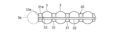
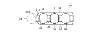
- the holding belt 30 includes a plurality of spacer portions 31 arranged in a line at regular intervals, and a pair of coupling belt portions 32 that connect the spacer portions 31, and the spacer portions and the coupling belt portions are made of synthetic resin. It is manufactured by injection molding.
- the holding belt 30 has flexibility as described above, and repeats stretching and bending when circulating in the endless circulation path together with the balls 3. At this time, it is only the coupling belt portion 32 that exhibits flexibility, and the coupling belt portion 32 can be flexed more freely than the spacer portion 31.
- Each spacer portion 31 is provided with a concave seat 33 having a curvature similar to the spherical surface of the ball 3, and a space between adjacent spacer portions is a pocket 34 for accommodating the ball. Further, the end spacer portion 31a located at the end of the holding belt 30 is also formed in the same shape as the other spacer portions 31, and a free ball 3a described later is provided in the end spacer portion 31a in the endless circulation path. It comes into sliding contact with the concave seat 33a.
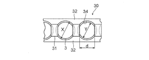
- the diameter X of the accommodation pocket 34 of the ball 3 provided on the holding belt 30 is set slightly larger than the diameter Y of the ball 3.
- the distance d between the spacer portions 31 adjacent to each other is set to be smaller than the diameter Y of the ball 3, and the ball 3 accommodated in the pocket 34 may fall out between the spacer portions 31 located on both sides. Absent.
- the rolling element may be a roller.
- the concave seat 33 formed in the spacer portion 31 is a concave seat having a curvature approximate to the outer peripheral surface of the roller.
- the concave seat 33 formed in the spacer portion 31 is not essential, and from the viewpoint of avoiding direct contact between the rolling elements, the spacer portion 31 may be a simple flat plate. There is no problem.
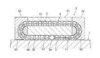
- the holding belt containing the ball 3 in the pocket 34 is incorporated in the endless circulation path 6. Both end portions of the holding belt 30 face each other inside the infinite circulation path 6, and a ball (hereinafter referred to as “free ball”) 3 a not accommodated in the pocket 34 is disposed therebetween.
- the free balls 3 a are the same as the balls 3 arranged in the pockets 34 of the holding belt 30, and a load is applied between the track rail 1 and the block main body like the other balls 3. .
- the spherical surface of the free ball 3a is in contact with the concave seat 33 of the end spacer portion 31a of the holding belt. Accordingly, a large number of balls 3 are arranged in the infinite circulation path 6 at a constant interval corresponding to the thickness of the spacer portion 31.
- the path length A of the endless circulation path 6 is set smaller than the sum of the total length B of the holding belt 30 and the diameter C of the free ball 3a. Has been. That is, (B + C)> A It is.
- the path length of the endless circulation path 6 is the length of one round of the locus drawn by the center of the ball 3 in the endless circulation path.
- the total length B of the holding belt 30 is different from the deepest portion of the concave seat 33a of the holding belt when the end spacer 31a is formed with the concave seat 33a in contact with the free ball 3a. This is the distance to the deepest part of the end concave seat 33a.
- the holding belt 30 is incorporated in the endless circulation path 6 in a state of being compressed in the longitudinal direction, and the pair of end spacer portions 31a positioned at both ends of the holding belt 30 are always provided with the free balls. It will come into contact with 3a.
- the diameter X of each pocket 34 of the holding belt 30 is set to be larger than the diameter Y of the ball 3 accommodated therein, and the distance between the ball 3 accommodated in the pocket 34 and the spacer portion 31 is set. There is a gap (XY) between them. Therefore, by eliminating this gap, the holding belt 30 can be compressed without difficulty, and at this time, the individual coupling belt portions 32 are slightly compressed and bent.
- the infinite circulation path 6 has a path length A, a total length B of the holding belt 30, a diameter C of the free ball 3 a, a diameter X of the pocket 34 of the holding belt 30, a diameter Y of the ball 3, and is arranged on the holding belt 30. If the total number Z of balls 3 to be played is set, the end spacer portion 31a of the holding belt 30 is inserted into the endless spacer 3 while holding one free ball 3a between both ends of the holding belt 30 incorporated in the endless circulation path 6. It is possible to always press the free ball 3a.
- the holding belt 30 and the free ball 3a are incorporated in the endless circulation path 6 so as to satisfy the above-described conditions, the circulation direction of the holding belt 30 in the endless circulation path 6 can be reduced. Since the front end always presses the rear end, fluctuations in the pulling force acting on the holding belt 30 can be reduced, and uneven wear of the holding belt 30 in the endless circulation path 6 can be prevented. It becomes.
Landscapes
- Engineering & Computer Science (AREA)
- General Engineering & Computer Science (AREA)
- Mechanical Engineering (AREA)
- Bearings For Parts Moving Linearly (AREA)
- Rolling Contact Bearings (AREA)
Abstract
保持ベルトが転動体と共に無限循環路内を循環する際に、当該保持ベルトに対して作用する引っ張り力を軽減し、保持ベルトの偏摩耗を防止することが可能な運動案内装置であって、軌道レール(1)と、前記軌道レールを転走する多数の転動体(3)と、前記転動体の無限循環路(6)を有すると共に前記軌道レールに沿って運動自在な移動ブロック(2)と、所定間隔で前記転動体を収容するポケット(34)が形成されると共に、前記無限循環路に組み込まれて前記転動体と共に当該無限循環路内を移動する保持ベルト(30)と、を備えており、前記保持ベルトは前記無限循環路内において一対の端部が1個の自由転動体(3a)を介して互いに対向し、以下の条件を満たしている。 (X-Y)×Z>(B+C)-A>0 A:無限循環路の経路長、B:保持ベルト全長、C:自由転動体の直径、X:ポケット径、Y:転動体の直径、Z:前記保持ベルトに配列される転動体数
Description
本発明は、工作機械のワークテーブルや各種搬送装置のテーブルを軌道レールに沿って自在に案内する運動案内装置に関する。
この種の運動案内装置としては特許文献1に開示されるものが知られている。この運動案内装置は、ベッド等の固定部に敷設される軌道レールと、この軌道レールに沿って自在に移動可能であると共に案内対象であるテーブル等の可動体を固定可能な移動ブロックとを備えている。前記移動ブロックはボール又はローラといった複数の転動体を介して前記軌道レールに組み付けられており、前記軌道レールには長手方向に沿って転動体の転走面が形成されている。前記移動ブロックには、前記軌道レールの転走面と対向する転動体の転走面が設けられると共に、当該転走面の一端から多端へ前記転動体を循環させる無限循環路が設けられており、前記転動体が当該無限循環路内を循環することにより、前記移動ブロックが前記軌道レールに沿って自在に運動を行うことが可能となっている。
また、前記無限循環路内には前記転動体の間隔を一定に保持するための保持ベルトが当該転動体と共に組み込まれている。前記保持ベルトは合成樹脂等の可撓性を有する材料から成形されており、当該保持ベルトには転動体を収容するポケットが一定の間隔で配列されている。また、保持ベルトはその全長が無限循環路の経路長よりも短く設定されており、無限循環路に組み込んだ際に、両端部が当該無限循環路内で間隔を空けて互いに向かい合っている。転動体はこの保持ベルトのポケット内で回転しながら前記軌道レールの転走面及び前記移動ブロックの転走面を転走し、ボールが無限循環路内を循環するのに伴い、当該保持ベルトも前記無限循環路内を循環する。
前記移動ブロックが有する転動体の無限循環路は、負荷通路と、この負荷通路と平行に設けられた戻し通路と、前記負荷通路と戻し通路の端部同士を接続する一対の方向転換路とから構成されている。前記負荷通路は前記軌道レールの転走面と前記移動ブロックの転走面とが対向する領域であり、前記転動体は軌道レールと移動ブロックとの間で荷重を負荷しながら当該負荷通路を転走する。一方、前記戻し通路及び前記一対の方向転換路は前記転動体を前記負荷通路の終端から始端へ戻すための無負荷通路であり、前記転動体は当該通路において何ら荷重を負荷していない。
このため、前記軌道レールと前記移動ブロックとの間に相対的な運動が生じると、前記負荷通路内の転動体は強制的に転がされて当該通路内を進行することになるが、前記戻し通路及び前記一対の方向転換路内の転動体は自ら転動せず、前記保持ベルトを介して負荷通路内の転動体に引っ張られ、あるいは押されて当該戻し通路及び一対の方向転換路を進行することになる。
前述したように、前記保持ベルトは両端部が互いに向かい合うようにして前記無限循環路内に組み込まれているので、このような無限循環路内における転動体の動きに起因し、前記保持ベルトにはその端部が前記負荷通路に出入りする際に循環方向に沿った引っ張り力が繰り返し作用することになる。これに伴い、当該保持ベルトが方向転換路に設けられたベルト案内溝に対して部分的に強く擦れて偏摩耗が促進される懸念があった。
本発明はこのような課題に鑑みなされたものであり、その目的とするところは、保持ベルトが転動体と共に無限循環路内を循環する際に、当該保持ベルトに対して作用する引っ張り力を軽減し、保持ベルトの偏摩耗を防止することが可能な運動案内装置を提供することにある。
すなわち、本発明の運動案内装置は、軌道レールと、前記軌道レールを転走する多数の転動体と、前記転動体の無限循環路を有すると共に前記軌道レールに沿って運動自在な移動ブロックと、所定間隔で前記転動体を収容するポケットが形成されると共に、前記無限循環路に組み込まれて前記転動体と共に当該無限循環路内を移動する保持ベルトと、を備えており、前記保持ベルトは前記無限循環路内において一対の端部が1個の自由転動体を介して互いに対向し、以下の条件、
(X-Y)×Z>(B+C)-A>0
A:無限循環路の経路長 X:ポケット径
B:保持ベルト全長 Y:転動体の直径
C:自由転動体の直径 Z:前記保持ベルトに配列される転動体数
を満たすものである。
(X-Y)×Z>(B+C)-A>0
A:無限循環路の経路長 X:ポケット径
B:保持ベルト全長 Y:転動体の直径
C:自由転動体の直径 Z:前記保持ベルトに配列される転動体数
を満たすものである。
本発明によれば、前記保持ベルトは長手方向に押し縮められた状態で無限循環路に組み込まれるので、前記保持ベルトの両端部が自由転動体を介して常に互いを押し合っており、前記保持ベルトの循環に伴って当該保持ベルトに作用する引っ張り力が軽減され、当該保持ベルトの偏摩耗を防止することが可能となる。
以下、添付図面を用いて本発明の運動案内装置を詳細に説明する。
図1は本発明を適用可能な運動案内装置の一例を示す斜視図である。この運動案内装置は、直線状に延びる軌道レール1と、転動体としての多数のボール3を介して前記軌道レール1に組付けられた移動ブロック2とから構成されており、固定部に前記軌道レール1を敷設し、前記移動ブロック2に対して各種の可動体を搭載することで、かかる可動体を軌道レール1に沿って往復移動自在に案内することができるようになっている。
前記軌道レール1は略断面四角形状の長尺体に形成されている。この軌道レール1には長手方向に所定の間隔をおいて上面から底面に貫通するボルト取付け孔12が複数形成されており、これらボルト取付け孔12に挿入した固定ボルトを用いて、軌道レール1をベッド、コラム等の固定部に対して強固に固定することができるようになっている。前記軌道レール1の左右両側面には長手方向に沿って突部がそれぞれ設けられると共に、これら突部の上下にはボールの転走面11が1条ずつ設けられ、軌道レール全体としては4条の転走面11が設けられている。尚、前記軌道レール1に設けられる転走面11の条数はこれに限られるものではない。
一方、前記移動ブロック2は、大きく分けて、金属製のブロック本体21と、このブロック本体21の移動方向の両端に装着される一対の合成樹脂製のエンドプレート22とから構成されている。この移動ブロック2は前記軌道レールの各転走面11に対応してボール3の無限循環路を複数備えており、かかる無限循環路は前記移動ブロック2の両端に前記一対のエンドプレートを固定することによって完成している。各無限循環路には可撓性の保持ベルト30が組み込まれており、かかる保持ベルト30には多数のボール3が一列に配列されている。従って、前記移動ブロック2が前記軌道レール1の長手方向へ動かされ、前記ボール3が前記軌道レール1の転走面を転がると、前記保持ベルト30がボール3と一緒に前記無限循環路を循環する。
また、前記移動ブロックには当該移動ブロックと軌道レールとの隙間を密閉する各種シール部材4,5,7が固定されており、軌道レール1に付着した塵芥などが前記無限循環路の内部に侵入するのを防止している。尚、図1は前記無限循環路内におけるボール3及び保持ベルト30の存在を把握できるように、前記移動ブロック2の全体の1/4を切り欠いて描いてある。
図2及び図3は前記ボール3が配列された前記保持ベルト30の一部を示すものであり、当該保持ベルト30の長手方向の端部を含んでいる。前記保持ベルト30は、一定間隔で一列に配列された複数のスペーサ部31と、これらスペーサ部31を連結する一対の結合ベルト部32とから構成され、これらスペーサ部と結合ベルト部は合成樹脂の射出成形によって製作されている。前記保持ベルト30は前述のごとく可撓性を備え、前記無限循環路内をボール3と一緒に循環する際に、伸展と湾曲を繰り返すことになる。この際、可撓性を発揮しているのは専ら前記結合ベルト部32であり、当該結合ベルト部32は前記スペーサ部31に比べて自由に撓むことが可能である。
各スペーサ部31には前記ボール3の球面に近似した曲率の凹面座33が設けられており、互いに隣接するスペーサ部の間が前記ボールを収容するポケット34になっている。また、前記保持ベルト30の端部に位置する末端スペーサ部31aも他のスペーサ部31と同じ形状に形成されており、前記無限循環路内では後述する自由ボール3aが末端スペーサ部31aの具備する凹面座33aに摺接するようになっている。
図4に示すように、前記保持ベルト30に設けたボール3の収容ポケット34の直径Xはボール3の直径Yよりも僅かに大きく設定されている。但し、互いに隣接するスペーサ部31の間の距離dはボール3の直径Yよりも小さく設定されており、前記ポケット34に収容されたボール3は両側に位置するスペーサ部31の間から抜け落ちることがない。
尚、図2乃至図4を用いて説明した実施形態では本発明の転動体としてボールを用いたが、当該転動体はローラであってもよい。その場合、前記スペーサ部31に形成する凹面座33はローラの外周面に近似した曲率の凹面座となる。また、前記スペーサ部31に形成された凹面座33は必須のものではなく、転動体同士の直接の接触を回避するという観点からすれば、当該スペーサ部31は単なる平板状のものであっても差し支えない。
図5は前記無限循環路6を示す断面図である。前記無限循環路6は、負荷通路60、戻し通路61及び一対の方向転換路62で構成されている。前記移動ブロック2を構成するブロック本体21には、前記軌道レール1の転走面11と対向する転走面23が形成されており、ボール3は軌道レール1の転走面11とブロック本体21の転走面23との間で荷重を負荷しながら転がる。前記無限循環路6のうち、このようにボール3が荷重を負荷しながら転動している通路部分が前記負荷通路60である。また、前記ブロック本体21には前記負荷通路60と平行に前記戻し通路61が形成されている。通常、この戻し通路61は前記ブロック本体21を貫通して設けられており、その内径はボール3の直径よりも僅かに大きく設定されている。一方、前記一対の方向転換路62は前記負荷通路60の長手方向の両側に位置して、当該負荷通路60の端部と前記戻し通路61の端部とを接続している。各方向転換路62は前記エンドプレート22に設けられており、一対のエンドプレート22を前記ブロック本体21の両端の所定の位置に固定することにより、前記方向転換路62が前記負荷通路60と前記戻し通路61とを接続し、前記ボール3が循環可能な無限循環路6が完成する。
前記無限循環路6にはボール3を前記ポケット34に収容した前記保持ベルトが組み込まれる。前記保持ベルト30の両端部は当該無限循環路6の内部で互いに対向し、それらの間には前記ポケット34に収容されていないボール(以下、「自由ボール」という)3aが配置されている。この自由ボール3aは前記保持ベルト30のポケット34に配列されたボール3と同一のものであり、他のボール3と同様に前記軌道レール1と前記ブロック本体との間で荷重を負荷している。また、当該自由ボール3aの球面は前記保持ベルトの末端スペーサ部31aの凹面座33に当接している。従って、前記無限循環路6内には前記スペーサ部31の厚みに相当する一定の間隔で多数のボール3が配列されていることになる。
前記自由ボール3aと前記末端スペーサ31aの凹面座33を常に接触させるため、前記無限循環路6の経路長Aは前記保持ベルト30の全長Bと前記自由ボール3aの直径Cの和よりも小さく設定されている。すなわち、
(B+C)>A
である。ここで、前記無限循環路6の経路長とは、当該無限循環路内でボール3の中心が描く軌跡の一周分の長さである。また、前記保持ベルト30の全長Bとは、前記末端スペーサ部31aに前記自由ボール3aと接する凹面座33aが形成されている場合には、当該保持ベルトの一旦の凹面座33aの最深部から他端の凹面座33aの最深部までの距離である。
(B+C)>A
である。ここで、前記無限循環路6の経路長とは、当該無限循環路内でボール3の中心が描く軌跡の一周分の長さである。また、前記保持ベルト30の全長Bとは、前記末端スペーサ部31aに前記自由ボール3aと接する凹面座33aが形成されている場合には、当該保持ベルトの一旦の凹面座33aの最深部から他端の凹面座33aの最深部までの距離である。
従って、以下の式、
δ=(B+C)-A>0
が満足されれば、前記保持ベルト30はその長手方向へ押し縮められた状態で前記無限循環路6に組み込まれ、当該保持ベルト30の両端に位置する一対の末端スペーサ部31aは常に前記自由ボール3aと接触することになる。
δ=(B+C)-A>0
が満足されれば、前記保持ベルト30はその長手方向へ押し縮められた状態で前記無限循環路6に組み込まれ、当該保持ベルト30の両端に位置する一対の末端スペーサ部31aは常に前記自由ボール3aと接触することになる。
一方、前記無限循環路6に対して前記保持ベルト30及び自由ボール3aを組み込むためには、当該保持ベルト30の全長を前述の長さδだけ長手方向へ押し縮めることが必要である。この点に関し、前記保持ベルト30の各ポケット34の直径Xはそこに収容されるボール3の直径Yよりも大きく設定しており、当該ポケット34に収容されたボール3と前記スペーサ部31との間に隙間(X-Y)が存在する。従って、この隙間を排除することにより、前記保持ベルト30を無理なく押し縮めることが可能であり、この際に個々の結合ベルト部32はわずかに圧縮されて撓んだ状態となる。
前記保持ベルト30に配列されるボール3の総数をZとした場合、各ボール3とスペーサ部31との隙間を排除するように当該保持ベルト30を押し縮めると、その最大量は、
δmax=(X-Y)Z
となる。すなわち、このδmaxまでは前記スペーサ部31を押し潰すことなく、前記保持ベルト30の全長をその長手方向へ無理なく押し縮めることができる。
δmax=(X-Y)Z
となる。すなわち、このδmaxまでは前記スペーサ部31を押し潰すことなく、前記保持ベルト30の全長をその長手方向へ無理なく押し縮めることができる。
以上から明らかなように、以下の条件、
(X-Y)×Z>(B+C)-A>0
を満たすように、無限循環路6の経路長A、保持ベルト30の全長B、自由ボール3aの直径C、保持ベルト30のポケット34の直径X、ボール3の直径Y、前記保持ベルト30に配列されるボール3の総数Zを設定すれば、前記無限循環路6に組み込んだ保持ベルト30の両端部の間に1個の自由ボール3aを挟みつつ、当該保持ベルト30の末端スペーサ部31aを前記自由ボール3aに常に圧接させておくことが可能となる。
(X-Y)×Z>(B+C)-A>0
を満たすように、無限循環路6の経路長A、保持ベルト30の全長B、自由ボール3aの直径C、保持ベルト30のポケット34の直径X、ボール3の直径Y、前記保持ベルト30に配列されるボール3の総数Zを設定すれば、前記無限循環路6に組み込んだ保持ベルト30の両端部の間に1個の自由ボール3aを挟みつつ、当該保持ベルト30の末端スペーサ部31aを前記自由ボール3aに常に圧接させておくことが可能となる。
前記無限循環路6内で前記保持ベルト30がボール3と共に一方向へ循環している場合、当該保持ベルト30は前記負荷通路60内を転走しているボール3によって動かされることから、無限循環路6内における保持ベルト30の両端部の位置に応じて、当該保持ベルト30には大きな引っ張り力が作用することになる。
その際、前述した条件を満たすように前記無限循環路6内に保持ベルト30と自由ボール3aを組み込んであれば、当該無限循環路6内における保持ベルト30の循環方向に関し、前記保持ベルト30の前端が常に後端を押圧することになるので、前記保持ベルト30に作用する引っ張り力の変動を軽減することができ、無限循環路6内における前記保持ベルト30の偏摩耗を防止することが可能となる。
尚、本発明はボールを転動体とした運動案内装置だけでなく、ローラを転動体とした運動案内装置にも適用可能である。また、図1を用いて具体的に示した運動案内装置はあくまでも一例であり、本発明を適用可能な運動案内装置の形状はこれに限定されるものではない。
Claims (4)
- 軌道レール(1)と、前記軌道レールを転走する多数の転動体(3)と、前記転動体の無限循環路(6)を有すると共に前記軌道レールに沿って運動自在な移動ブロック(2)と、
所定間隔で前記転動体を収容するポケットが形成されると共に、前記無限循環路に組み込まれて前記転動体と共に当該無限循環路内を移動する保持ベルト(30)と、を備え、
前記保持ベルトは前記無限循環路内において一対の端部が1個の自由転動体(3a)を介して互い
に対向し、
以下の条件、
(X-Y)×Z>(B+C)-A>0
A:無限循環路の経路長 X:ポケット径
B:保持ベルト全長 Y:転動体の直径
C:自由転動体の直径 Z:前記保持ベルトに配列される転動体数
を満たすことを特徴とする運動案内装置。 - 前記保持ベルト(30)は、一定間隔で一列に配列された複数のスペーサ部(31)と、これらスペーサ部を連結すると共に可撓性を有する一対の結合ベルト部(32)とから構成され、前記転動体の収容ポケット(34)は互いに隣接する一対のスペーサ部の間に設けられていることを特長とする請求項1記載の運動案内装置。
- 各スペーサ部(31)は前記転動体(3)が接する凹面座(33)を有しており、前記保持ベルトの端部に位置する末端スペーサ部(31a)は前記自由転動体(3a)が接する凹面座(33a)を有していることを特長とする請求項2記載の運動案内装置。
- 前記自由転動体(3a)は前記保持ベルト(30)の収容ポケット(34)に収容された転動体(3)と同一直径であり、前記軌道レール(1)と前記移動ブロック(2)との間で荷重を負荷していることを特長とする請求項1記載の運動案内装置。
Priority Applications (3)
| Application Number | Priority Date | Filing Date | Title |
|---|---|---|---|
| DE112016005728.8T DE112016005728T5 (de) | 2015-12-15 | 2016-12-01 | Bewegunsführungsvorrichtung |
| CN201680066512.5A CN108350937B (zh) | 2015-12-15 | 2016-12-01 | 运动引导装置 |
| US15/781,964 US10436248B2 (en) | 2015-12-15 | 2016-12-01 | Motion guide device |
Applications Claiming Priority (2)
| Application Number | Priority Date | Filing Date | Title |
|---|---|---|---|
| JP2015-244324 | 2015-12-15 | ||
| JP2015244324A JP6373246B2 (ja) | 2015-12-15 | 2015-12-15 | 運動案内装置 |
Publications (1)
| Publication Number | Publication Date |
|---|---|
| WO2017104428A1 true WO2017104428A1 (ja) | 2017-06-22 |
Family
ID=59056345
Family Applications (1)
| Application Number | Title | Priority Date | Filing Date |
|---|---|---|---|
| PCT/JP2016/085731 Ceased WO2017104428A1 (ja) | 2015-12-15 | 2016-12-01 | 運動案内装置 |
Country Status (6)
| Country | Link |
|---|---|
| US (1) | US10436248B2 (ja) |
| JP (1) | JP6373246B2 (ja) |
| CN (1) | CN108350937B (ja) |
| DE (1) | DE112016005728T5 (ja) |
| TW (1) | TWI700440B (ja) |
| WO (1) | WO2017104428A1 (ja) |
Families Citing this family (6)
| Publication number | Priority date | Publication date | Assignee | Title |
|---|---|---|---|---|
| JP6385384B2 (ja) * | 2016-04-11 | 2018-09-05 | Thk株式会社 | 転がり案内装置 |
| JP1586244S (ja) * | 2017-05-09 | 2020-09-14 | ||
| USD875150S1 (en) * | 2017-05-31 | 2020-02-11 | Thk Co., Ltd. | End plate for motion guide device |
| JP6834789B2 (ja) | 2017-06-05 | 2021-02-24 | コベルコ建機株式会社 | ストラットの引き起こし方法、およびクレーン |
| TWI708019B (zh) * | 2019-03-11 | 2020-10-21 | 精浚科技股份有限公司 | 線性滑軌的滾動模組及鏈帶 |
| CN111720445B (zh) * | 2019-03-20 | 2022-02-01 | 精浚科技股份有限公司 | 线性滑轨的滚动模块及链带 |
Citations (5)
| Publication number | Priority date | Publication date | Assignee | Title |
|---|---|---|---|---|
| JPH0552217A (ja) * | 1991-08-22 | 1993-03-02 | T H K Kk | ボールチエイン |
| JPH112241A (ja) * | 1997-06-13 | 1999-01-06 | Thk Kk | 転動体付ベルト |
| JP2007154905A (ja) * | 2005-11-30 | 2007-06-21 | Nsk Ltd | 直動案内装置用転動体収容ベルトおよび直動案内装置、並びに転動体収容ベルト製造用金型 |
| JP2008185045A (ja) * | 2007-01-26 | 2008-08-14 | Nsk Ltd | 直動案内装置 |
| WO2010074155A1 (ja) * | 2008-12-26 | 2010-07-01 | Thk株式会社 | 転動体リテーナ及びこれを用いた無限循環式直線運動装置 |
Family Cites Families (7)
| Publication number | Priority date | Publication date | Assignee | Title |
|---|---|---|---|---|
| JP3243415B2 (ja) | 1996-06-27 | 2002-01-07 | テイエチケー株式会社 | 摺動案内装置及びその有端転動体チェーン |
| JPH112243A (ja) * | 1997-06-10 | 1999-01-06 | Nippon Seiko Kk | 潤滑剤供給体 |
| JP2000046052A (ja) * | 1998-07-28 | 2000-02-15 | Nippon Seiko Kk | 直動案内装置 |
| JP2000120674A (ja) * | 1998-10-12 | 2000-04-25 | Nsk Ltd | 直線運動案内装置 |
| DE102006059161B4 (de) * | 2005-12-15 | 2023-01-12 | Nsk Ltd. | Lineare Führungsvorrichtung |
| US20080085067A1 (en) * | 2006-10-05 | 2008-04-10 | Hsin-Tsun Hsu | Linear Guideway with Synchronously Operating Spacers |
| US8408796B1 (en) * | 2011-11-21 | 2013-04-02 | Chieftech Precision Co., Ltd. | Rolling element retainer belt and linear motion guide apparatus |
-
2015
- 2015-12-15 JP JP2015244324A patent/JP6373246B2/ja active Active
-
2016
- 2016-12-01 DE DE112016005728.8T patent/DE112016005728T5/de active Pending
- 2016-12-01 CN CN201680066512.5A patent/CN108350937B/zh active Active
- 2016-12-01 US US15/781,964 patent/US10436248B2/en active Active
- 2016-12-01 WO PCT/JP2016/085731 patent/WO2017104428A1/ja not_active Ceased
- 2016-12-07 TW TW105140464A patent/TWI700440B/zh active
Patent Citations (5)
| Publication number | Priority date | Publication date | Assignee | Title |
|---|---|---|---|---|
| JPH0552217A (ja) * | 1991-08-22 | 1993-03-02 | T H K Kk | ボールチエイン |
| JPH112241A (ja) * | 1997-06-13 | 1999-01-06 | Thk Kk | 転動体付ベルト |
| JP2007154905A (ja) * | 2005-11-30 | 2007-06-21 | Nsk Ltd | 直動案内装置用転動体収容ベルトおよび直動案内装置、並びに転動体収容ベルト製造用金型 |
| JP2008185045A (ja) * | 2007-01-26 | 2008-08-14 | Nsk Ltd | 直動案内装置 |
| WO2010074155A1 (ja) * | 2008-12-26 | 2010-07-01 | Thk株式会社 | 転動体リテーナ及びこれを用いた無限循環式直線運動装置 |
Also Published As
| Publication number | Publication date |
|---|---|
| JP6373246B2 (ja) | 2018-08-15 |
| DE112016005728T5 (de) | 2018-09-06 |
| JP2017110704A (ja) | 2017-06-22 |
| US10436248B2 (en) | 2019-10-08 |
| CN108350937B (zh) | 2019-12-20 |
| TW201732170A (zh) | 2017-09-16 |
| US20180355915A1 (en) | 2018-12-13 |
| CN108350937A (zh) | 2018-07-31 |
| TWI700440B (zh) | 2020-08-01 |
Similar Documents
| Publication | Publication Date | Title |
|---|---|---|
| JP6373246B2 (ja) | 運動案内装置 | |
| CN108779797B (zh) | 滚动导向装置 | |
| JP6173217B2 (ja) | 運動案内装置 | |
| CN107614904B (zh) | 滚动引导装置 | |
| JP3263005B2 (ja) | 転がり案内装置 | |
| JP2017110704A5 (ja) | ||
| US7585112B2 (en) | Linear motion guide apparatus | |
| JP3343195B2 (ja) | ローラチェイン | |
| TWI686551B (zh) | 複數排滾動體收容束帶及運動導引裝置 | |
| CN107448473B (zh) | 滚动引导装置 | |
| JP2008175324A (ja) | ボール連結体 | |
| JP2012026534A (ja) | 転動体保持スペーサ及びこれを用いた運動案内装置 | |
| CN113661332A (zh) | 运动引导装置 | |
| JP6338853B2 (ja) | ローラ連結体及びこれを用いた転がり案内装置 | |
| JP6364157B2 (ja) | 運動案内装置 | |
| JP3436708B2 (ja) | 直線運動案内装置 | |
| JP2012002361A (ja) | 案内装置用ローラーリテーナ及びこれを用いた案内装置 | |
| JP4501862B2 (ja) | 転動体収容ベルトおよび直動案内装置 | |
| JP2008240882A (ja) | リニアガイド装置 | |
| JP2002339969A (ja) | ローラチェイン | |
| JP4600340B2 (ja) | 転動体収容ベルトおよび直動案内装置 | |
| JP2007132403A5 (ja) | ||
| JP2006242388A (ja) | ボールチェーン | |
| JP2011094764A (ja) | 転動体連結帯及びこの転動体連結帯を備える運動案内装置 | |
| KR20060060798A (ko) | 가이드 벨트 |
Legal Events
| Date | Code | Title | Description |
|---|---|---|---|
| 121 | Ep: the epo has been informed by wipo that ep was designated in this application |
Ref document number: 16875411 Country of ref document: EP Kind code of ref document: A1 |
|
| WWE | Wipo information: entry into national phase |
Ref document number: 112016005728 Country of ref document: DE |
|
| 122 | Ep: pct application non-entry in european phase |
Ref document number: 16875411 Country of ref document: EP Kind code of ref document: A1 |