WO2017082012A1 - Dispositif d'humidification et machine de production de carton ondulé - Google Patents
Dispositif d'humidification et machine de production de carton ondulé Download PDFInfo
- Publication number
- WO2017082012A1 WO2017082012A1 PCT/JP2016/081128 JP2016081128W WO2017082012A1 WO 2017082012 A1 WO2017082012 A1 WO 2017082012A1 JP 2016081128 W JP2016081128 W JP 2016081128W WO 2017082012 A1 WO2017082012 A1 WO 2017082012A1
- Authority
- WO
- WIPO (PCT)
- Prior art keywords
- liquid
- chamber
- liner paper
- roll
- blade
- Prior art date
Links
Images


Classifications
-
- B—PERFORMING OPERATIONS; TRANSPORTING
- B31—MAKING ARTICLES OF PAPER, CARDBOARD OR MATERIAL WORKED IN A MANNER ANALOGOUS TO PAPER; WORKING PAPER, CARDBOARD OR MATERIAL WORKED IN A MANNER ANALOGOUS TO PAPER
- B31F—MECHANICAL WORKING OR DEFORMATION OF PAPER, CARDBOARD OR MATERIAL WORKED IN A MANNER ANALOGOUS TO PAPER
- B31F1/00—Mechanical deformation without removing material, e.g. in combination with laminating
- B31F1/20—Corrugating; Corrugating combined with laminating to other layers
- B31F1/24—Making webs in which the channel of each corrugation is transverse to the web feed
- B31F1/26—Making webs in which the channel of each corrugation is transverse to the web feed by interengaging toothed cylinders cylinder constructions
- B31F1/28—Making webs in which the channel of each corrugation is transverse to the web feed by interengaging toothed cylinders cylinder constructions combined with uniting the corrugated webs to flat webs ; Making double-faced corrugated cardboard
- B31F1/2845—Details, e.g. provisions for drying, moistening, pressing
-
- B—PERFORMING OPERATIONS; TRANSPORTING
- B28—WORKING CEMENT, CLAY, OR STONE
- B28B—SHAPING CLAY OR OTHER CERAMIC COMPOSITIONS; SHAPING SLAG; SHAPING MIXTURES CONTAINING CEMENTITIOUS MATERIAL, e.g. PLASTER
- B28B19/00—Machines or methods for applying the material to surfaces to form a permanent layer thereon
-
- B—PERFORMING OPERATIONS; TRANSPORTING
- B31—MAKING ARTICLES OF PAPER, CARDBOARD OR MATERIAL WORKED IN A MANNER ANALOGOUS TO PAPER; WORKING PAPER, CARDBOARD OR MATERIAL WORKED IN A MANNER ANALOGOUS TO PAPER
- B31F—MECHANICAL WORKING OR DEFORMATION OF PAPER, CARDBOARD OR MATERIAL WORKED IN A MANNER ANALOGOUS TO PAPER
- B31F1/00—Mechanical deformation without removing material, e.g. in combination with laminating
- B31F1/20—Corrugating; Corrugating combined with laminating to other layers
- B31F1/24—Making webs in which the channel of each corrugation is transverse to the web feed
- B31F1/26—Making webs in which the channel of each corrugation is transverse to the web feed by interengaging toothed cylinders cylinder constructions
- B31F1/28—Making webs in which the channel of each corrugation is transverse to the web feed by interengaging toothed cylinders cylinder constructions combined with uniting the corrugated webs to flat webs ; Making double-faced corrugated cardboard
- B31F1/2818—Glue application specially adapted therefor
-
- B—PERFORMING OPERATIONS; TRANSPORTING
- B31—MAKING ARTICLES OF PAPER, CARDBOARD OR MATERIAL WORKED IN A MANNER ANALOGOUS TO PAPER; WORKING PAPER, CARDBOARD OR MATERIAL WORKED IN A MANNER ANALOGOUS TO PAPER
- B31F—MECHANICAL WORKING OR DEFORMATION OF PAPER, CARDBOARD OR MATERIAL WORKED IN A MANNER ANALOGOUS TO PAPER
- B31F1/00—Mechanical deformation without removing material, e.g. in combination with laminating
- B31F1/36—Moistening and heating webs to facilitate mechanical deformation and drying deformed webs
-
- B—PERFORMING OPERATIONS; TRANSPORTING
- B05—SPRAYING OR ATOMISING IN GENERAL; APPLYING FLUENT MATERIALS TO SURFACES, IN GENERAL
- B05C—APPARATUS FOR APPLYING FLUENT MATERIALS TO SURFACES, IN GENERAL
- B05C1/00—Apparatus in which liquid or other fluent material is applied to the surface of the work by contact with a member carrying the liquid or other fluent material, e.g. a porous member loaded with a liquid to be applied as a coating
- B05C1/003—Apparatus in which liquid or other fluent material is applied to the surface of the work by contact with a member carrying the liquid or other fluent material, e.g. a porous member loaded with a liquid to be applied as a coating incorporating means for heating or cooling the liquid or other fluent material
-
- B—PERFORMING OPERATIONS; TRANSPORTING
- B05—SPRAYING OR ATOMISING IN GENERAL; APPLYING FLUENT MATERIALS TO SURFACES, IN GENERAL
- B05C—APPARATUS FOR APPLYING FLUENT MATERIALS TO SURFACES, IN GENERAL
- B05C1/00—Apparatus in which liquid or other fluent material is applied to the surface of the work by contact with a member carrying the liquid or other fluent material, e.g. a porous member loaded with a liquid to be applied as a coating
- B05C1/04—Apparatus in which liquid or other fluent material is applied to the surface of the work by contact with a member carrying the liquid or other fluent material, e.g. a porous member loaded with a liquid to be applied as a coating for applying liquid or other fluent material to work of indefinite length
- B05C1/08—Apparatus in which liquid or other fluent material is applied to the surface of the work by contact with a member carrying the liquid or other fluent material, e.g. a porous member loaded with a liquid to be applied as a coating for applying liquid or other fluent material to work of indefinite length using a roller or other rotating member which contacts the work along a generating line
- B05C1/0813—Apparatus in which liquid or other fluent material is applied to the surface of the work by contact with a member carrying the liquid or other fluent material, e.g. a porous member loaded with a liquid to be applied as a coating for applying liquid or other fluent material to work of indefinite length using a roller or other rotating member which contacts the work along a generating line characterised by means for supplying liquid or other fluent material to the roller
-
- B—PERFORMING OPERATIONS; TRANSPORTING
- B05—SPRAYING OR ATOMISING IN GENERAL; APPLYING FLUENT MATERIALS TO SURFACES, IN GENERAL
- B05C—APPARATUS FOR APPLYING FLUENT MATERIALS TO SURFACES, IN GENERAL
- B05C1/00—Apparatus in which liquid or other fluent material is applied to the surface of the work by contact with a member carrying the liquid or other fluent material, e.g. a porous member loaded with a liquid to be applied as a coating
- B05C1/04—Apparatus in which liquid or other fluent material is applied to the surface of the work by contact with a member carrying the liquid or other fluent material, e.g. a porous member loaded with a liquid to be applied as a coating for applying liquid or other fluent material to work of indefinite length
- B05C1/08—Apparatus in which liquid or other fluent material is applied to the surface of the work by contact with a member carrying the liquid or other fluent material, e.g. a porous member loaded with a liquid to be applied as a coating for applying liquid or other fluent material to work of indefinite length using a roller or other rotating member which contacts the work along a generating line
- B05C1/0826—Apparatus in which liquid or other fluent material is applied to the surface of the work by contact with a member carrying the liquid or other fluent material, e.g. a porous member loaded with a liquid to be applied as a coating for applying liquid or other fluent material to work of indefinite length using a roller or other rotating member which contacts the work along a generating line the work being a web or sheets
-
- B—PERFORMING OPERATIONS; TRANSPORTING
- B31—MAKING ARTICLES OF PAPER, CARDBOARD OR MATERIAL WORKED IN A MANNER ANALOGOUS TO PAPER; WORKING PAPER, CARDBOARD OR MATERIAL WORKED IN A MANNER ANALOGOUS TO PAPER
- B31F—MECHANICAL WORKING OR DEFORMATION OF PAPER, CARDBOARD OR MATERIAL WORKED IN A MANNER ANALOGOUS TO PAPER
- B31F1/00—Mechanical deformation without removing material, e.g. in combination with laminating
- B31F1/20—Corrugating; Corrugating combined with laminating to other layers
- B31F1/24—Making webs in which the channel of each corrugation is transverse to the web feed
- B31F1/26—Making webs in which the channel of each corrugation is transverse to the web feed by interengaging toothed cylinders cylinder constructions
- B31F1/28—Making webs in which the channel of each corrugation is transverse to the web feed by interengaging toothed cylinders cylinder constructions combined with uniting the corrugated webs to flat webs ; Making double-faced corrugated cardboard
- B31F1/2831—Control
-
- B—PERFORMING OPERATIONS; TRANSPORTING
- B31—MAKING ARTICLES OF PAPER, CARDBOARD OR MATERIAL WORKED IN A MANNER ANALOGOUS TO PAPER; WORKING PAPER, CARDBOARD OR MATERIAL WORKED IN A MANNER ANALOGOUS TO PAPER
- B31F—MECHANICAL WORKING OR DEFORMATION OF PAPER, CARDBOARD OR MATERIAL WORKED IN A MANNER ANALOGOUS TO PAPER
- B31F1/00—Mechanical deformation without removing material, e.g. in combination with laminating
- B31F1/20—Corrugating; Corrugating combined with laminating to other layers
- B31F1/24—Making webs in which the channel of each corrugation is transverse to the web feed
- B31F1/26—Making webs in which the channel of each corrugation is transverse to the web feed by interengaging toothed cylinders cylinder constructions
- B31F1/28—Making webs in which the channel of each corrugation is transverse to the web feed by interengaging toothed cylinders cylinder constructions combined with uniting the corrugated webs to flat webs ; Making double-faced corrugated cardboard
- B31F1/2845—Details, e.g. provisions for drying, moistening, pressing
- B31F1/285—Heating or drying equipment
-
- B—PERFORMING OPERATIONS; TRANSPORTING
- B31—MAKING ARTICLES OF PAPER, CARDBOARD OR MATERIAL WORKED IN A MANNER ANALOGOUS TO PAPER; WORKING PAPER, CARDBOARD OR MATERIAL WORKED IN A MANNER ANALOGOUS TO PAPER
- B31F—MECHANICAL WORKING OR DEFORMATION OF PAPER, CARDBOARD OR MATERIAL WORKED IN A MANNER ANALOGOUS TO PAPER
- B31F1/00—Mechanical deformation without removing material, e.g. in combination with laminating
- B31F1/20—Corrugating; Corrugating combined with laminating to other layers
- B31F1/24—Making webs in which the channel of each corrugation is transverse to the web feed
- B31F1/26—Making webs in which the channel of each corrugation is transverse to the web feed by interengaging toothed cylinders cylinder constructions
- B31F1/28—Making webs in which the channel of each corrugation is transverse to the web feed by interengaging toothed cylinders cylinder constructions combined with uniting the corrugated webs to flat webs ; Making double-faced corrugated cardboard
- B31F1/2845—Details, e.g. provisions for drying, moistening, pressing
- B31F1/2877—Pressing means for bringing facer sheet and corrugated webs into contact or keeping them in contact, e.g. rolls, belts
- B31F1/2881—Pressing means for bringing facer sheet and corrugated webs into contact or keeping them in contact, e.g. rolls, belts for bringing a second facer sheet into contact with an already single faced corrugated web
-
- B—PERFORMING OPERATIONS; TRANSPORTING
- B32—LAYERED PRODUCTS
- B32B—LAYERED PRODUCTS, i.e. PRODUCTS BUILT-UP OF STRATA OF FLAT OR NON-FLAT, e.g. CELLULAR OR HONEYCOMB, FORM
- B32B2255/00—Coating on the layer surface
- B32B2255/12—Coating on the layer surface on paper layer
Definitions
- the present invention relates to a humidifier that humidifies liner paper after being heated by a preheater and before being bonded to a core paper, and a corrugating machine using the humidifier.
- the corrugated machine manufacturing line has a mill roll stand equipped with a base liner paper, a front liner base paper, a core liner base paper roll, and a corrugated machine.
- Splicer as a splicing device for continuously supplying the corrugated cardboard toward the back, and liner paper that forms the core paper fed from the mill roll stand into a corrugated shape and paste applied to the top of the corrugated shape
- the liner paper is heated with a preheater prior to the lamination of the liner paper to the core paper in a single facer or double facer. This is because in the liner paper laminating operation, the liner paper is preheated to a predetermined liner paper temperature so that the liner paper is satisfactorily pasted. Therefore, in general, heating is performed by bringing liner paper into contact with the peripheral surface (heating surface) of a roll-shaped preheater and transporting it.
- the amount of heating applied to the liner paper increases as the time during which the liner paper is in contact with the roll-shaped preheater is longer, that is, the winding angle (wrap angle) of the liner paper with respect to the preheater is larger. Therefore, the heating amount of the liner paper is set by adjusting the wrap angle.
- the wrap angle adjusts the contact area of liner paper to the preheater by moving the rolls arranged in parallel with the preheater on the upstream side and downstream side of the preheater in the circumferential direction at equal intervals with respect to the peripheral surface of the preheater. To set.
- the liner paper is improved by increasing the wrap angle and increasing the heating amount in order to complement the increase in heat capacity of the liner paper. Preheated to the predetermined liner paper temperature to be bonded.
- the moisture of the liner paper that easily penetrates the paste is generally 3 to 6% by weight.
- the moisture of the liner paper especially the surface layer
- This reduction in moisture creates a problem of reducing the penetration depth, which is the depth at which glue permeates the liner paper per unit time.
- Patent Document 1 (see FIG. 1), an appropriate amount of moisture is contained in the liner paper heated by the preheater, and a watering roll is attached to the preheater so that the downstream double facer can be well bonded to the core paper.
- a corrugating machine disposed downstream is disclosed.
- Patent Document 2 (see FIG. 8) discloses a watering roll device for humidifying liner paper disposed between a heating portion and a cooling portion of a double facer.
- Patent Document 2 aims to prevent warping in the width direction of the liner paper by appropriately humidifying the liner paper conveyed to the cooling unit with a watering roll.
- JP 2008-055777 A Japanese Patent Laid-Open No. 11-221870
- the watering roll in Patent Document 1 is immersed in water stored in a pan to form a water film on the outer peripheral surface, and this water film is applied to the surface of the liner paper that comes into contact.
- water heated to a predetermined temperature heat supplied to the pan. If the temperature of the water is low, the temperature of the liner paper is lowered, the liner paper temperature necessary for the pasting operation in the next process cannot be maintained, and a case of poor bonding may occur, so this is avoided. .
- Patent Document 1 since the entire upper part (hereinafter referred to as an open part) of the pan storing the humidified heating water is opened, a large gap is formed between the pan and the watering roll. . As a result, the heat of the heating water is dissipated from the opening, and it is difficult to maintain the heating water at a predetermined high temperature (for example, 90 ° C.).
- a predetermined high temperature for example, 90 ° C.
- Patent Document 2 aims to prevent warping in the width direction of liner paper, although a humidifying device for liner paper is disclosed, temperature control of water for humidifying liner paper is disclosed. There is room for improvement.
- An object of the present invention is to provide a humidifying device and a corrugating machine that can suppress the release of heat from heated water as much as possible and can humidify liner paper at an appropriate temperature. To do.
- a humidifying device that humidifies a liner paper that is conveyed in one direction and is bonded to the core paper through glue applied to the top of the corrugated core paper that has been formed into a waveform,
- a liquid application roll disposed downstream of a pre-heater for heating the liner paper prior to the bonding, and applying a heated liquid to the liner paper;
- a chamber having an internal space that is disposed opposite to the peripheral surface of the liquid roll and is supplied with the liquid;
- the chamber has an opening that communicates with the internal space and supplies the liquid to the peripheral surface of the liquid application roll, and a direction orthogonal to the axial direction of the liquid application roll of the opening Is a humidifying device characterized in that the length of the humidifier is smaller than the diameter of the liquid application roll.
- the heated liquid for humidification is held in the interior space of the chamber having high hermeticity, the liquid is brought into contact with the liquid application roll through the opening of the chamber, and the liquid application roll in the opening is further provided. Since the length in the width direction in the direction orthogonal to the axis is smaller than the diameter of the liquid application roll, the liquid application roll can substantially function as a lid for the opening.
- an outer surface of the opening member extending in the axial direction forming the opening is inclined obliquely downward from a horizontal plane. This is because the droplets adhering to the surface naturally fall by the dead weight and are discarded.
- a plurality of the blades are arranged in parallel in the axial direction and have a blade driving mechanism that drives each blade in a direction in which the blade comes in contact with and separates from the surface of the liquid application roll. This is because it is possible to give a distribution to the amount of liquid attached in the axial direction of the roll peripheral surface of the liquid application roll.
- the blade is disposed downstream of the chamber in the rotation direction of the liquid application roll. This is because the amount of liquid adhering to the peripheral surface of the liquid application roll can be adjusted before applying the liquid to the liner paper.
- the blade is constituted by the opening member that forms the opening of the chamber. This is because the opening member of the chamber can also serve as a blade function.
- the heating means is preferably disposed in the chamber. This is because the liquid can be heated immediately before being applied to the liner paper, so that a temperature drop due to heat radiation can be suppressed.
- the liquid path is preferably a circulation path having a supply path for supplying the liquid into the chamber and a recovery path for returning the liquid stored in the pan to the supply path.
- This is because the heating water can be reused to increase the water heating efficiency. That is, since the liquid stored in the pan has been heated once, it has a certain temperature and can be raised to a predetermined temperature with a small heating amount.
- the paste is starch paste, and the temperature of the liquid is desirably 90 ° C or higher. This is because the liner paper temperature preheated by the preheater can be maintained.
- a preheater that heats a sheet-like liner paper that is transported in one direction and is bonded to the core paper via glue applied to the top of the corrugated core paper that is formed into a waveform.
- the corrugating machine is characterized in that the humidifier described in any one of 1) to 15) above is disposed downstream of the machine.
- the humidifier as described above is provided downstream of the preheater, the optimum condition is obtained by obtaining the optimum moisture content of the liner paper while maintaining the temperature of the liner paper heated by the preheater at the optimum bonding temperature.
- the above-mentioned pasting can be realized.
- the heating liquid of the humidifier is held in the chamber, temperature management becomes easy, and maintenance of the appropriate temperature of the liner paper can be easily realized.
- the heated liquid for humidification is held in the internal space of the chamber having high hermeticity, and the liquid is supplied to the liquid application roll through the opening of the chamber. Since the length in the direction orthogonal to the axial direction of the application roll is smaller than the diameter of the application roll, the application roll can substantially function as a lid for the opening. As a result, heat release from the liquid held in the chamber is suppressed as much as possible, and the liner paper can be humidified at an appropriate temperature by this liquid. Moreover, even if it is a heavy liner paper with a large heat capacity, the temperature of the liner paper can be set to an appropriate temperature for bonding without reducing the conveying speed, and good bonding strength can be obtained. .
- the humidifier as described above is provided downstream of the preheater, the optimum moisture content of the liner paper is obtained while maintaining the temperature of the liner paper heated by the preheater at the optimum bonding temperature.
- the heating liquid of the humidifier is held in the chamber, the temperature can be easily maintained, and the maintenance of the appropriate temperature of the liner paper can be easily realized.
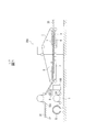
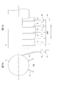
- FIG. 1 is a schematic side view showing a double facer of a corrugating machine according to an embodiment of the present invention and its vicinity.
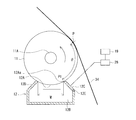
- FIG. 2 is a schematic diagram showing the configuration of the humidifier according to the embodiment of the present invention.
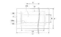
- FIG. 3 is a schematic plan view for explaining the relationship between the size of the liquid application roll (water application roll) and the opening of the chamber.
- FIG. 4 is a schematic diagram when the relative position of the chamber with respect to the liquid application roll is adjusted by the gap adjustment mechanism.
- FIG. 5 is a schematic side view for explaining a range in which the blade for water scraping that can be set defined by the positional relationship between the liquid application roll and the chamber is provided.
- 6A and 6B are schematic views showing the chamber blade together with the liquid application roll, in which FIG.
- FIG. 6A is a cross-sectional view and FIG. 6B is a front view seen from a direction perpendicular thereto.
- 7A and 7B are schematic views showing a doctor blade together with a liquid application roll, in which FIG. 7A is a cross-sectional view, and FIG. 7B is a side view as seen from a direction perpendicular thereto.
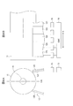
- FIG. 8 is a schematic diagram showing the positional relationship between the two for explaining the limit of the position of the chamber relative to the liquid application roll.
- FIG. 1 is a schematic side view showing a double facer of a corrugating machine according to this embodiment and its vicinity.
- the double facer 200 manufactures a double-faced cardboard 35 by bonding a front liner paper 34 to a single-faced cardboard 31 manufactured by a single facer (not shown). Therefore, starch paste (hereinafter referred to as “glue”) is formed on the corrugated top portion 32a of the core paper 32 of the single-sided cardboard 31 while conveying the single-sided cardboard 31 supplied from the single facer in one direction (from left to right in FIG. 1).
- glue starch paste
- the front liner paper 34 is bonded through
- the front liner paper 34 is heated by the preheater 1 prior to the bonding of the single-sided cardboard 31 and the front liner paper 34, and the humidifying device ( Heating water is applied at 100, which will be described in detail later.
- the front liner paper 34 is fed out from the base paper roll 33 mounted on the mill roll stand and preheated by the preheater 1.
- the preheated front liner paper 34 is humidified by the humidifier 100 and then introduced into the double facer 200.
- the double facer 200 includes a hot plate group 2 that forms a travel path of the single-sided cardboard 31 and the front liner paper 34, and the single-sided cardboard paper 31 and the front liner paper 34 are overlapped to run on the hot plate group 2.
- heating steam is supplied to the hollow portion of the hot plate group 2, and the upper surface of each hot plate is heated to 180 ° C., for example.
- An upper conveyor 3 and a lower conveyor 4 that sandwich and convey a double-sided cardboard 35 formed by laminating a single-sided cardboard 31 and a front liner paper 34 above the hot-plate group 2 and downstream of the hot-plate group 2. Is arranged.
- a pressurizing device 5 that pressurizes the back surface of the upper conveyor 3 by an air pressurizing device or a weight roll and thus presses the single-sided cardboard 31 and the front liner paper 34 from above is provided on the upper part of the hot plate group 2.
- a lower roll group 6 that supports the lower conveyor 4 from the back surface, and an upper weight roll group 7 disposed on the back surface of the upper conveyor 3 on the downstream side of the pressurizing device 5 are provided.
- the single-sided cardboard 31 and the front liner paper 34 introduced between the hot plate group 2 and the pressure device 5 of the double facer 200 were applied to the top 32 a of the core paper 32 of the single-sided cardboard 31 by the gluing device 8. It is placed in a state of being joined via the raw starch solution, and is sandwiched and conveyed between the upper conveyor 3 and the lower conveyor 4. Then, the raw starch liquid is gelatinized by the heat from the front liner paper 34 that receives the temperature while running while sliding in contact with the hot plate group 2, and the front liner paper 34 is made by the adhesive force. Is bonded to the core paper 32 to form a double-sided cardboard 35. The formed double-sided cardboard 35 is transported by the upper conveyor 3 and the lower conveyor 4 and is transported to the next process.
- the raw starch solution is applied to the top 32a of the core paper 32, and the front liner paper 34 is bonded to each top 32a.
- the front liner paper 34 contains appropriate moisture at the time of bonding together with the application of “pressing force” to the bonding portion and the “heating time” of a certain level or more. It is important to keep it humid.
- a humidifier 100 is disposed downstream of the preheater 1 and upstream of the double facer 200.
- the front liner paper 34 is heated to a predetermined temperature by the preheater 1. This is because the starch paste applied to the top 32a of the core paper 32 by the gluing device 8 is gelled by raising the temperature when the core paper 32 of the single-sided cardboard 31 and the front liner paper 34 are bonded together, This is because, in the double facer 200, the core paper 32 and the front liner paper 34 are satisfactorily bonded to each other.
- the moisture content of the front liner paper 34 is reduced by heating in the preheater 1, the moisture content of the front liner paper 34 should be maintained at the optimum moisture content (about 3 to 6% by weight) for bonding. Becomes difficult.
- the front liner paper 34 it is desirable to apply moisture to the front liner paper 34 and humidify it appropriately.
- moisture when moisture is applied for humidification, if the temperature of the moisture to be applied is low, the temperature of the front liner paper 34 is lower than the temperature required for bonding. Therefore, the water used for humidification is heated so that the temperature of the front liner paper 34 at the time of bonding becomes optimum (specifically, it will be described in detail later).
- the heated water for humidification is also referred to as heated water.
- the heating of the front liner paper 34 by the preheater 1 is performed by adjusting the position of an adjustment roll (not shown) arranged in parallel with the axis of the roll forming the preheater 1 on the upstream side and the downstream side of the preheater 1. Is going. That is, the contact area (lap angle) of the front liner paper 34 with respect to the preheater 1 is adjusted by moving the adjustment roll in the circumferential direction at equal intervals with respect to the peripheral surface of the preheater 1. As a result, the heating amount supplied from the preheater 1 to the front liner paper 34 can be adjusted. Incidentally, the heating amount increases as the wrap angle increases. Further, the wrap angle (heating amount) is adjusted to be a predetermined value based on the heat capacity defined by the weight of the front liner paper 34 or the like.
- FIG. 2 is a schematic diagram showing the configuration of the humidifier according to the present embodiment, and is a diagram showing in detail the configuration of the humidifier 100 shown as a block in FIG.
- the humidifying device 100 includes a watering roll (liquid applying roll) 11 and a chamber 12.
- the front liner paper 34 heated by the preheater 1 is brought into contact with the peripheral surface of the watering roll 11, the heated water adhering to the peripheral surface of the watering roll 11 is applied to the front liner paper 34.
- the watering roll 11 is in a vertically downward rotational phase, and its peripheral surface comes into contact with heated water inside the chamber 12 vertically below the rotating shaft 11A via the opening 12A.
- the peripheral surface of the watering roll 11 is flat, for example, and is subjected to metal (chrome) plating. Moreover, you may form a recessed part in the surrounding surface of the watering roll 11 by engraving.
- the amount of heated water applied is adjusted.
- the front liner paper 34 that has passed through the preheater 1 is guided by the guide rolls 15 ⁇ / b> A, 15 ⁇ / b> B, and 15 ⁇ / b> C, and is conveyed toward the double facer 200 in a state where moisture (heated water) is applied by contact with the watering roll 11.
- the amount of heated water applied may be adjusted by moving the guide rolls 15B and 15C to change the contact area (wrap angle) of the front liner paper 34 to the watering roll 11.
- the chamber 12 has opening members 12C and 12D.
- the opening members 12C and 12D are opposed to each other on the downstream side and the upstream side in the rotation direction of the watering roll 11, and are extended in the axial direction of the rotation shaft 11A. Two sides facing each other are defined. Heated water is supplied to the internal space 12B of the chamber 12 communicated via the opening 12A.
- the heated water is stored in the water tank 16, pumped up from the water tank 16 by the pump 17 driven to rotate by the motor 25, and supplied to the internal space 12 ⁇ / b> B through the supply path 13 ⁇ / b> A of the liquid path 13 as described above.
- the heated water in the internal space 12B of the chamber 12 is pressed against the peripheral surface of the watering roll 11 with a predetermined pressure through the opening 12A. Further, the heated water overflowing outside the chamber 12 through the gap between the opening 12 ⁇ / b> A of the chamber 12 and the watering roll 11 is stored in a pan 18 disposed below the chamber 12. That is, the liquid path 13 in the present embodiment has a heated water supply path 13A from the water tank 16 to the chamber 12, and a heated water recovery path 13B from the pan 18 to the water tank 16, and both paths 13A, The liquid path 13 is formed as a circulation path of heated water by 13B.
- the discharge pressure of the pump 17 in the present embodiment is controlled according to the rotation speed of the motor 25.
- the rotation speed of the motor 25 is controlled by a command from the control device 19.
- the pressure of the heated water in the chamber 12 is adjusted.
- Such pressure adjustment of the heating water can also be realized by controlling the supply pressure with a pressure adjusting valve (not shown) while keeping the rotation speed of the pump 17 constant.
- the water tank 16 is provided with a temperature sensor 20 that detects the temperature of the heated water in the water tank 16 and a heater 22 that heats the heated water in the water tank 16.
- the temperature sensor 20 and the heater 22 are respectively provided in the water tank 16. Soaked in heated water.
- the temperature of the heated water in the water tank 16 (in other words, the temperature of the heated water supplied to the chamber 12 via the supply path 13A) is based on the temperature detected by the temperature sensor 20, and the temperature controller 21 is connected to the AC power supply AC and the heater 22.
- the control is performed by turning on / off the switch SW1 interposed between them (turning on / off the power supply to the heater 22).
- the control signal for the switch SW1 output from the temperature controller 21 includes a temperature command value indicating the set temperature of the heated water in the water tank 16 output from the control device 19, and a real-time temperature detection value detected by the temperature sensor 20. And is generated based on the result of comparing. That is, if the temperature command value is higher than the temperature detection value by a predetermined temperature, the switch SW1 is turned on and the heater 22 is turned on. If the temperature command value is lower than the temperature detection value by a predetermined temperature, the switch SW1 is turned off and the heater 22 is turned on. In this way, the temperature of the heated water is maintained within a certain range from the set temperature.
- the temperature of the heated water stored in the water tank 16 is the surface liner paper 34 between the preheater 1 and the watering roll 11 (after being heated by the preheater 1 and before being heated by the watering roll 11). It is determined based on the temperature. This is when the front liner paper 34 is coated with heating water by the watering roll 11 and then bonded to the top 32a of the core paper 32 of the single-sided cardboard 31 with the double facer 200 (see FIG. 1; the same applies hereinafter). This is because the surface temperature of the front liner paper 34 is controlled so that the bonding is performed at an appropriate temperature in consideration of the gelatinization temperature of the starch paste.
- the temperature sensor 23 detects the surface temperature of the front liner paper 34 on the downstream side of the preheater 1 and the upstream side of the watering roll 11, that is, between the preheater 1 and the watering roll 11. Is arranged.
- the temperature sensor 23 sends temperature information indicating the detected surface temperature of the front liner paper 34 to the control device 19.
- the control device 19 has a temperature so that the temperature of the front liner paper 34 becomes an appropriate temperature when being bonded to the single-sided cardboard 31.
- the temperature command value for the controller 21 is determined.
- the temperature of the heated water is set to 90 ° C. or higher so that the temperature of the front liner paper 34 preheated by the preheater 1 can be maintained.
- the rotating peripheral speed of the watering roll 11 in this embodiment is controlled by an inverter-driven motor 26. As the rotating peripheral speed of the watering roll 11 increases, the amount of heated water applied to the front liner paper 34 also increases. However, if the rotating peripheral speed is too high, the surface of the water film on the peripheral surface of the watering roll 11 will be reduced. There is a case where the surface liner paper 34 is roughed to cause uneven humidification. Therefore, in the present embodiment, the surface liner paper 34 can be uniformly humidified without roughening the surface of the water film on the peripheral surface of the watering roll 11, and a water film having an appropriate thickness is formed on the surface liner paper 34.
- a set value for the rotational peripheral speed is determined so that the front liner paper 34 can be appropriately humidified.
- the set value is stored in the control device 19 and is output from the control device 19 to the speed controller 24 as a rotation command value.
- the speed controller 24 converts the voltage of the AC power supply AC into a voltage corresponding to the rotation command value, and supplies it to the inverter-driven motor 26.
- the motor 26 is rotationally driven at a rotational speed based on the rotation command value output from the control device 19.
- the setting value of the rotational peripheral speed of the watering roll 11 is obtained in advance by experiment or the like so that the water film surface of the peripheral surface of the watering roll 11 is not roughened. do it.
- the heat dissipation from the heated water held in the chamber 12 is suppressed as much as possible, and the temperature of the heated water in the chamber 12 It is devised to be kept at a predetermined temperature.
- FIG. 3 is a schematic plan view for explaining the relationship between the size of the watering roll 11 and the opening 12 ⁇ / b> A of the chamber 12.
- opening length the length L2 of the opening 12A in the axial direction of the watering roll 11
- roll length the length L1 in the coaxial direction of the watering roll 11
- opening width the length W (hereinafter referred to as opening width) W in the direction orthogonal to the axial length of the opening 12A is smaller than the diameter (hereinafter referred to as roll diameter) ⁇ of the watering roll 11. It is formed.
- the opening 12A of the chamber 12 is covered with the watering roll 11, thereby suppressing the heat dissipation from the heating water from the opening 12A.
- the opening width W is formed to be smaller than the roll diameter ⁇ (opening width W ⁇ roll diameter ⁇ )
- the opening length L2 is formed to be shorter than the roll length L1. If (opening length L2 ⁇ roll length L1), at least if the opening width W is smaller than the roll diameter ⁇ (opening width W ⁇ roll diameter ⁇ ), the effect of suppressing the heat dissipation of the heating water can be obtained.
- the opening width W is made smaller than the roll diameter ⁇ and the opening length L2 is made shorter than the roll length L1, it is naturally possible to obtain a better heat dissipation suppression effect. it can.
- the opening length L2 is preferably set to a dimension larger than the entire width of the liner paper 34 so that moisture can be applied to the entire width of the liner paper 34.
- the gap is preferably as small as possible, but it is defined by the amount of humidification between the four sides defining the opening 12A and one side 12Aa of the opening 12A on the most downstream side in the roll rotation direction. It is necessary to provide a slight gap. Thus, the most effective heat retention can be ensured by ensuring that the remaining three sides defining the opening 12A are in contact with the peripheral surface of the watering roll 11 while ensuring the gap. It is important that the gap between the watering roll 11 does not roughen the surface of the water film of the watering roll 11. In addition, what is necessary is just to determine the optimal value (setting value) of the clearance gap between the watering roll 11 and the opening part 12A by experiment.
- a seal member is provided on three sides excluding one side 12Aa formed by the opening member 12C, and the chamber 12 is in contact with the watering roll 11 via the seal member. In this case, even better heat retention can be ensured.
- a gap between the watering roll 11 and the opening 12 ⁇ / b> A of the chamber 12 is provided by providing a gap adjusting mechanism 27 that adjusts the relative position of the chamber 12 with respect to the watering roll 11. It can also be configured to be able to adjust.
- the structure which adjusts the position of the chamber 12 with respect to the watering roll 11 by moving the chamber 12 linearly in the vertical direction by the gap adjusting mechanism 27 is exemplified.
- the gap adjusting mechanism 27 can be used to adjust the gap between the opening 12A and the watering roll 11 to a desired size.
- the amount of water to be attached to the peripheral surface of the roll 11 can be arbitrarily set, and as a result, the humidification amount for the front liner paper 34 can be arbitrarily set.
- the operation of the gap adjustment mechanism 27 is controlled by the control device 19.
- the thickness of the water film on the peripheral surface of the watering roll 11, and consequently the surface liner paper 34 is appropriately scraped off by heating water adhering to the peripheral surface of the watering roll 11.
- the amount of heating water applied is adjusted. That is, the scraping of the heated water adhering to the peripheral surface of the watering roll 11 is performed after the watering roll 11 comes into contact with the heated water in the chamber 12 along with its rotation and causes the heated water to adhere to the peripheral surface. And before applying to the front liner paper 34.
- the scraping of the heated water is a range between “the inner space 12 ⁇ / b> B of the chamber 12” and “the contact point P between the watering roll 11 and the front liner paper 34”. This can be done with ⁇ .
- the opening member that forms the opening 12A of the chamber 12 and extends in the axial direction X of the watering roll 11 A blade (chamber blade) can also be formed using the opening member 12C on the downstream side in the rotation direction of the watering roll 11 among the 12C and 12D (the opening member 12C is hereinafter also referred to as the blade 12C).
- the lower end portion of the blade 12C is rotatably supported by the hinge portion 12E.
- the gap between the tip of the blade 12C and the peripheral surface of the watering roll 11 is easily adjusted, and the heated water is scraped from the peripheral surface of the watering roll 11.
- the amount to be taken can be set as appropriate.
- a hinge portion (not shown) is provided at the base end portion of the blade 14 so that the amount of rotation is adjusted and the peripheral surface of the watering roll 11 is provided.
- the amount of scraping of the heated water from the peripheral surface of the watering roll 11 can be appropriately set.
- the blades 12C and 14 as described above may be configured such that a plurality of blades 12C, 14 narrow in the axial direction X of the watering roll 11 are arranged in the axial direction X. Examples of such blades 12C and 14 will be described with reference to FIGS. 6A, 6B, 7A, and 7B.
- FIGS. 6A and 6B are schematic views showing a blade formed as a chamber blade together with a watering roll, in which FIG. 6A is a cross-sectional view and FIG. 6B is a front view as seen from a direction perpendicular thereto.
- the blade drive mechanism 28 individually adjusts the rotation amount (tilt) of each blade 12C, so that the tip of each blade 12C is appropriately adjusted with respect to the peripheral surface of the watering roll 11.
- the gap between the blade 12 and the peripheral surface of the watering roll 11 is adjusted for each blade 12C.
- Such individual adjustment makes it possible to change the distribution of the amount of scraping water with respect to the axial direction X of the watering roll 11.
- water films can be formed on the peripheral surface of the watering roll 11 with different film thicknesses depending on the position in the axial direction X.
- the surface liner paper 34 is humidified with water films of different thicknesses, so that the bonding conditions are optimized and the distribution of the amount of humidification of the surface liner paper 34 in the axial direction X is changed to optimize the bonding conditions.
- the warpage of the double-sided cardboard 35 in the axial direction X can be controlled.
- the blade 12C is a member constituting a part of the chamber 12, it is a member having a relatively large predetermined thickness. That is, even when each blade 12C is rotated independently, as shown by a broken line in FIG. 6A, the blades 12C adjacent in the axial direction X are partially overlapped by the thickness thereof, and each of the plurality of blades 12C is overlapped. A gap is prevented from being generated between them, and leakage of heated water through the gap is prevented.
- FIGS. 7A and 7B are schematic views showing blades (doctor blades) 14 formed separately from the chamber together with a watering roll.
- FIG. 7A is a cross-sectional view
- FIG. 7B is viewed from a direction perpendicular thereto. It is a front view.
- a plurality of narrow blades 14 are provided side by side in the axial direction X.
- Each blade 14 is individually rotated by a blade driving mechanism 29 around a hinge (not shown) at the base end.
- blade 14 is contacted / separated suitably with respect to the surrounding surface of the watering roll 11, and each clearance gap between each blade 14 and the surrounding surface of the watering roll 11 can be adjusted separately.
- each blade 14 is configured separately from the chamber 12 and is disposed downstream of the chamber 12 in the roll rotation direction. For this reason, each blade 14 will be arrange
- Both the blade 12C and the blade 14 adjust the gap with the watering roll 11 by changing the rotation amount with the base end portion as the rotation center and adjusting the inclination, thereby adjusting the watering roll 11.
- the quantity of the heating water made to adhere to the surrounding surface of this may be controlled, it does not restrict to this.
- the blade 12C and the blade 14 are formed so as to be able to advance and retreat in the respective longitudinal directions, the gap between the tips of the blades 12C and 14 and the peripheral surface of the watering roll 11 can be adjusted. Can be achieved.
- the control device 19 controls the blade drive mechanisms 28 and 29 that adjust the gap between the watering roll 11 and the blades 12C and 14.
- the watering roll 11 can function as a lid of the opening 12A.
- the airtightness of the internal space 12B of the chamber 12 can be enhanced, and the heated water heated to a predetermined temperature can be held in the internal space 12B having a high airtightness.
- the heat dissipation in the heating water in the chamber 12 can be suppressed as much as possible and maintained at a predetermined temperature. Therefore, the front liner paper 34 can be humidified with heated water having a predetermined temperature that takes into account the gelatinization temperature of the starch paste.
- the temperature of the front liner paper 34 can be set to a temperature suitable for the gelatinization of the glue, and the water content of the front liner paper 34 can be set to a water content suitable for the penetration of the glue.
- the single-sided cardboard 31 (core paper 32) and the front liner paper 34 can be bonded well.
- the humidifier 100 as described above is provided downstream of the preheater 1, so that the temperature and moisture content of the front liner paper 34 heated by the preheater 1 are bonded to each other by glue. It can be suitable, and the bonding of the front liner paper 34 to the core paper 32 on the downstream side of the humidifying device 100 under the optimum conditions can be realized.
- the present invention is not limited to this.
- the arrangement of the chamber 12 may be a position shifted from the vertical lower position of the watering roll 11 to some extent on the downstream side or the upstream side in the roll rotation direction (counterclockwise direction in this example).
- an example of the limit of the range allowed as the position of the chamber 12 is shown by a two-dot chain line in FIG.
- the chamber 12 has the opening member 12C on the downstream side (right side in the drawing) with respect to the rotation direction of the watering roll 11 with respect to the vertical center line VC, and the opening member on the upstream side (left side in the drawing).
- Each of the outer surfaces of 12D is a surface (including a vertical surface) that is inclined obliquely downward from the horizontal plane toward the outside of the chamber 12 (as it is separated from the watering roll 11 if expressed differently). Need to be. This is because the water droplets W1 and W2 that have exuded from the chamber 12 between the watering roll 11 and the upper end portions of the opening members 12C and 12D are dropped by their own weight and are discharged.
- the outer surface of the opening member 12C and the opening member 12D is a surface (including a horizontal surface) inclined obliquely upward toward the outside of the chamber 12, the watering roll 11 and the opening member 12C. , 12D, water exuding from the chamber 12 is accumulated as water droplets W1, W2, and in some cases, the accumulated water droplets W1, W2 are formed on the peripheral surface of the watering roll 11. If the surface liner paper 34 is scattered or scattered on the front liner paper 34 (see FIG. 2), an adverse situation such as an adverse effect on the front liner paper 34 occurs. Therefore, the position of the chamber 12 indicated by a two-dot chain line in FIG. 8 is the limit position of the allowable range.
- the outer surface of the opening member 12C and the opening member 12D refers to a surface of the opening member 12C and the opening member 12D that faces the outside of the chamber 12, that is, a surface opposite to the inner surface facing the internal space 12B. .
- the liquid path 13 for supplying water to the chamber 12 is a circulation path having the supply path 13A and the recovery path 13B including the pan 18, but in principle, only the supply path 13A may be used.
- the circulation path by configuring the circulation path, the heated water overflowing from the chamber 12 can be reused, and wasteful consumption of the heated water can be prevented.
- the temperature sensor 23 may be disposed on the downstream side of the watering roll 11 as long as it is upstream of the double facer 200.
- information on the temperature detected by the temperature sensor 23 is returned to the control device 19, where the temperature of the front liner paper 34 at the time of pasting by the double facer 200 is a predetermined temperature in consideration of the gelling temperature of the starch paste. This is because the temperature of the heated water is controlled so that
- the mounting position of the temperature sensor 20 for detecting the temperature of the heated water and the heater 22 for heating the heated water can detect the temperature of the heated water supplied to the chamber 12 such as in the chamber 12 or the liquid path 13. If it is a position which can be heated and a position where heated water can be heated, there is no particular limitation on the place. However, the mounting position of the temperature sensor 20 is optimal as long as the inside of the chamber 12 has solved the problem of installation space. This is because the temperature of the heated water immediately before adhering to the front liner paper 34 can be directly managed by the temperature sensor 20.
- a surfactant may be added to the heated water.
- the heated water can be easily soaked into the front liner paper 34. Thereby, the wetting time until heated water permeates sufficiently can be shortened, and the necessary penetration depth of the paste can be obtained in a short time.
- the back liner paper and the core paper are pasted together by glue even in the production of the single-sided cardboard 31 in the single facer, so that it is provided on the upstream side of the single facer.
- a similar humidifier 100 may be disposed between the preheater and the single facer. Thereby, favorable pasting with back liner paper and core paper can be performed.
- the humidifier 100 can be substituted for the preheater 1. In this case, heating by the preheater 1 can be stopped. In the case of a corrugating machine dedicated to lightweight liner paper, the preheater can be omitted by using the humidifier 100 as a preheater.
Landscapes
- Engineering & Computer Science (AREA)
- Mechanical Engineering (AREA)
- Chemical & Material Sciences (AREA)
- Ceramic Engineering (AREA)
- Machines For Manufacturing Corrugated Board In Mechanical Paper-Making Processes (AREA)
Abstract
L'invention concerne un dispositif d'humidification et une machine de production de carton ondulé avec lesquels le dégagement de chaleur provenant de l'eau chauffée peut être supprimé autant que possible et un papier doublure peut être humidifié à la température appropriée. L'invention réalise un dispositif d'humidification (100) destiné à humidifier un papier doublure de surface (34) fixé à un papier central par le biais d'une colle à l'amidon appliquée sur les sommets des ondes dans le papier central. Le dispositif d'humidification (100) comprend : un rouleau applicateur de liquide (11) destiné à appliquer de l'eau chauffée sur le papier doublure de surface (34), le rouleau applicateur de liquide (11) se trouvant en aval d'un préchauffeur (11) pour chauffer le papier doublure de surface (34) avant la fixation ; et une chambre (12) disposée en regard de la face périphérique du rouleau applicateur de liquide (11) et pourvue d'un espace interne (12B) vers lequel est acheminée l'eau chauffée ; la chambre (12) comprend en outre une ouverture (12A) servant à l'alimentation en eau chauffée de la face périphérique du rouleau applicateur de liquide (11), et la chambre (12) est formée de telle sorte que la longueur de l'ouverture (12A) dans la direction orthogonale à la direction axiale du rouleau applicateur de liquide (11) est inférieure au diamètre du rouleau applicateur de liquide (11).
Priority Applications (3)
| Application Number | Priority Date | Filing Date | Title |
|---|---|---|---|
| CN201680065437.0A CN108290364B (zh) | 2015-11-10 | 2016-10-20 | 加湿装置及瓦楞机 |
| EP16863976.3A EP3357679B1 (fr) | 2015-11-10 | 2016-10-20 | Dispositif d'humidification et machine de production de carton ondulé |
| US15/774,515 US20200247081A1 (en) | 2015-11-10 | 2016-10-20 | Humidifying device and corrugating machine |
Applications Claiming Priority (2)
| Application Number | Priority Date | Filing Date | Title |
|---|---|---|---|
| JP2015220422A JP6734041B2 (ja) | 2015-11-10 | 2015-11-10 | 加湿装置およびコルゲートマシン |
| JP2015-220422 | 2015-11-10 |
Publications (1)
| Publication Number | Publication Date |
|---|---|
| WO2017082012A1 true WO2017082012A1 (fr) | 2017-05-18 |
Family
ID=58694980
Family Applications (1)
| Application Number | Title | Priority Date | Filing Date |
|---|---|---|---|
| PCT/JP2016/081128 WO2017082012A1 (fr) | 2015-11-10 | 2016-10-20 | Dispositif d'humidification et machine de production de carton ondulé |
Country Status (5)
| Country | Link |
|---|---|
| US (1) | US20200247081A1 (fr) |
| EP (1) | EP3357679B1 (fr) |
| JP (1) | JP6734041B2 (fr) |
| CN (1) | CN108290364B (fr) |
| WO (1) | WO2017082012A1 (fr) |
Cited By (3)
| Publication number | Priority date | Publication date | Assignee | Title |
|---|---|---|---|---|
| CN107322985A (zh) * | 2017-06-16 | 2017-11-07 | 宁夏夏进制箱包装有限公司 | 防爆裂的瓦楞纸双压线装置 |
| WO2020149059A1 (fr) | 2019-01-17 | 2020-07-23 | 三菱重工機械システム株式会社 | Dispositif d'humidification de feuille, procédé et dispositif de fabrication de feuille de carton |
| CN112477295A (zh) * | 2020-12-28 | 2021-03-12 | 滁州卷烟材料厂 | 一种瓦楞纸板加湿方法 |
Families Citing this family (6)
| Publication number | Priority date | Publication date | Assignee | Title |
|---|---|---|---|---|
| CN109551826A (zh) * | 2018-12-26 | 2019-04-02 | 佛山市富利包装机械有限公司 | 全线湿部原纸对齐系统 |
| IT201900006568A1 (it) * | 2019-05-06 | 2020-11-06 | Fosber Spa | Metodo e dispositivo per il controllo della trazione del cartone ondulato nei piani caldi di una linea di produzione |
| JP7319149B2 (ja) * | 2019-09-10 | 2023-08-01 | レンゴー株式会社 | 段ボールシート製造装置 |
| CN112495714A (zh) * | 2020-12-26 | 2021-03-16 | 吴江市盛泽兴隆轧光厂 | 一种纺织复合机涂胶装置及其使用方法 |
| CN113771426B (zh) * | 2021-09-03 | 2023-06-30 | 上豪包装机械(镇江)有限公司 | 一种纸袋机伺服局部加湿装置及其使用方法 |
| CN115503292B (zh) * | 2022-10-19 | 2023-10-27 | 揭阳市合联纸业有限公司 | 一种瓦楞纸生产系统 |
Citations (4)
| Publication number | Priority date | Publication date | Assignee | Title |
|---|---|---|---|---|
| JPH0834081A (ja) * | 1994-07-22 | 1996-02-06 | Yoshizawa Kogyo Kk | コルゲートマシン |
| JPH11501263A (ja) * | 1995-02-27 | 1999-02-02 | ベーハーエス コルゲイテッド マシーネン ウント アンラーゲンバウ ゲゼルシャフト ミット ベシュレンクテル ハフツング | 段ボールの製造方法およびその装置 |
| JPH11221870A (ja) * | 1998-02-06 | 1999-08-17 | Mitsubishi Heavy Ind Ltd | コルゲートマシン |
| JP2008055777A (ja) * | 2006-08-31 | 2008-03-13 | Mitsubishi Heavy Ind Ltd | 段ボール紙の製造方法及び装置 |
Family Cites Families (11)
| Publication number | Priority date | Publication date | Assignee | Title |
|---|---|---|---|---|
| DE1240727B (de) * | 1964-11-03 | 1967-05-18 | Waldhof Zellstoff Fab | Verfahren und Vorrichtung zum Befeuchten von Wellpappe |
| DE1561494C3 (de) * | 1967-01-24 | 1974-12-05 | Harris-Intertype Corp., Cleveland, Ohio (V.St.A.) | Vorrichtung zur Herstellung von Wellpappe |
| SE463078B (sv) * | 1988-09-27 | 1990-10-08 | Btg Kaelle Inventing Ab | Paafoeringsanordning foer en- eller tvaasidig belaeggning av en loepande bana |
| WO1993019931A1 (fr) * | 1992-03-31 | 1993-10-14 | Ranpak Corp. | Procede et dispositif servant a fabriquer un produit de conditionnement elastique ameliore |
| CN2355872Y (zh) * | 1998-09-07 | 1999-12-29 | 季福宝 | 多功能纸板自动裱合机 |
| JP3457919B2 (ja) * | 1999-11-05 | 2003-10-20 | 三菱重工業株式会社 | コルゲートマシン |
| JP2008114468A (ja) * | 2006-11-02 | 2008-05-22 | Mitsubishi Heavy Ind Ltd | 段ボール紙の反り及び接着不良防止方法 |
| JPWO2014069307A1 (ja) * | 2012-10-30 | 2016-09-08 | キヤノン株式会社 | シート処理装置及び画像形成システム |
| CN204138992U (zh) * | 2014-08-07 | 2015-02-04 | 南通中大纸业有限公司 | 一种瓦楞纸蒸汽加湿装置 |
| CN204451454U (zh) * | 2015-02-26 | 2015-07-08 | 陕西科技大学 | 一种平版胶印机免酒精润版液刮板式清洁供水装置 |
| CN204602523U (zh) * | 2015-05-18 | 2015-09-02 | 天津鑫丰塑料制品有限公司 | 胶带底涂装置 |
-
2015
- 2015-11-10 JP JP2015220422A patent/JP6734041B2/ja active Active
-
2016
- 2016-10-20 EP EP16863976.3A patent/EP3357679B1/fr active Active
- 2016-10-20 CN CN201680065437.0A patent/CN108290364B/zh not_active Expired - Fee Related
- 2016-10-20 US US15/774,515 patent/US20200247081A1/en not_active Abandoned
- 2016-10-20 WO PCT/JP2016/081128 patent/WO2017082012A1/fr active Application Filing
Patent Citations (4)
| Publication number | Priority date | Publication date | Assignee | Title |
|---|---|---|---|---|
| JPH0834081A (ja) * | 1994-07-22 | 1996-02-06 | Yoshizawa Kogyo Kk | コルゲートマシン |
| JPH11501263A (ja) * | 1995-02-27 | 1999-02-02 | ベーハーエス コルゲイテッド マシーネン ウント アンラーゲンバウ ゲゼルシャフト ミット ベシュレンクテル ハフツング | 段ボールの製造方法およびその装置 |
| JPH11221870A (ja) * | 1998-02-06 | 1999-08-17 | Mitsubishi Heavy Ind Ltd | コルゲートマシン |
| JP2008055777A (ja) * | 2006-08-31 | 2008-03-13 | Mitsubishi Heavy Ind Ltd | 段ボール紙の製造方法及び装置 |
Cited By (4)
| Publication number | Priority date | Publication date | Assignee | Title |
|---|---|---|---|---|
| CN107322985A (zh) * | 2017-06-16 | 2017-11-07 | 宁夏夏进制箱包装有限公司 | 防爆裂的瓦楞纸双压线装置 |
| WO2020149059A1 (fr) | 2019-01-17 | 2020-07-23 | 三菱重工機械システム株式会社 | Dispositif d'humidification de feuille, procédé et dispositif de fabrication de feuille de carton |
| US11691376B2 (en) | 2019-01-17 | 2023-07-04 | Mitsubishi Heavy Industries Machinery Systems, Ltd. | Sheet humidifying device, method, and cardboard sheet manufacturing device |
| CN112477295A (zh) * | 2020-12-28 | 2021-03-12 | 滁州卷烟材料厂 | 一种瓦楞纸板加湿方法 |
Also Published As
| Publication number | Publication date |
|---|---|
| CN108290364B (zh) | 2020-09-25 |
| EP3357679A4 (fr) | 2018-12-26 |
| US20200247081A1 (en) | 2020-08-06 |
| EP3357679B1 (fr) | 2020-01-01 |
| CN108290364A (zh) | 2018-07-17 |
| EP3357679A1 (fr) | 2018-08-08 |
| JP2017087561A (ja) | 2017-05-25 |
| JP6734041B2 (ja) | 2020-08-05 |
Similar Documents
| Publication | Publication Date | Title |
|---|---|---|
| WO2017082012A1 (fr) | Dispositif d'humidification et machine de production de carton ondulé | |
| EP2391505B1 (fr) | Procédé de contrôle de l'humidité et de la température lors d'une opération d'ondulation | |
| WO2012071804A1 (fr) | Procédé de production et chaîne de production de carton ondulé doté d'une couverture préimprimée | |
| US10040266B2 (en) | Glue application device and glue application method for cardboard sheets and cardboard sheet manufacturing device | |
| US7976667B2 (en) | Machine for bonding films made of different materials in several layers, and the corresponding method | |
| CN103894319B (zh) | 一种封缄胶带涂布机及胶带涂布方法 | |
| JPH11221870A (ja) | コルゲートマシン | |
| CN201942949U (zh) | 预印面纸瓦楞纸板生产装置 | |
| WO2018205880A1 (fr) | Appareil de liaison pour carton ondulé | |
| KR101384365B1 (ko) | 포장지의 필름 합지방법 및 그 장치 | |
| CN104553236A (zh) | 一种节能环保的覆膜机 | |
| JPH11291366A (ja) | 片面段ボール製造方法および装置 | |
| JP2006218841A (ja) | ダンボール紙製造装置 | |
| JP2008055777A (ja) | 段ボール紙の製造方法及び装置 | |
| JP6323275B2 (ja) | Icカードの製造装置 | |
| JP3495425B2 (ja) | コルゲートマシン | |
| FI127490B (fi) | Aaltopahvin säätö- ja valmistuslaitteisto sekä säätö- ja valmistusmenetelmä | |
| CN211756635U (zh) | 一种适用于厚纸板的双面机 | |
| JP2002113799A (ja) | 両面段ボールの製造方法及びその製造装置 | |
| US11691376B2 (en) | Sheet humidifying device, method, and cardboard sheet manufacturing device | |
| JP2008088710A (ja) | シート貼着方法およびシート貼着装置 | |
| JP6584761B2 (ja) | Icカードの製造装置 | |
| JP2919824B1 (ja) | ダブルフェーサ | |
| JPS58220726A (ja) | 段ボ−ルシ−ト製造機における糊付け装置 | |
| JP2008062627A (ja) | 紙シートの加熱方法及び装置 |
Legal Events
| Date | Code | Title | Description |
|---|---|---|---|
| 121 | Ep: the epo has been informed by wipo that ep was designated in this application |
Ref document number: 16863976 Country of ref document: EP Kind code of ref document: A1 |
|
| WWE | Wipo information: entry into national phase |
Ref document number: 2016863976 Country of ref document: EP |
|
| NENP | Non-entry into the national phase |
Ref country code: DE |