WO2017082012A1 - Humidifying device and corrugating machine - Google Patents
Humidifying device and corrugating machine Download PDFInfo
- Publication number
- WO2017082012A1 WO2017082012A1 PCT/JP2016/081128 JP2016081128W WO2017082012A1 WO 2017082012 A1 WO2017082012 A1 WO 2017082012A1 JP 2016081128 W JP2016081128 W JP 2016081128W WO 2017082012 A1 WO2017082012 A1 WO 2017082012A1
- Authority
- WO
- WIPO (PCT)
- Prior art keywords
- liquid
- chamber
- liner paper
- roll
- blade
- Prior art date
Links
Images


Classifications
-
- B—PERFORMING OPERATIONS; TRANSPORTING
- B31—MAKING ARTICLES OF PAPER, CARDBOARD OR MATERIAL WORKED IN A MANNER ANALOGOUS TO PAPER; WORKING PAPER, CARDBOARD OR MATERIAL WORKED IN A MANNER ANALOGOUS TO PAPER
- B31F—MECHANICAL WORKING OR DEFORMATION OF PAPER, CARDBOARD OR MATERIAL WORKED IN A MANNER ANALOGOUS TO PAPER
- B31F1/00—Mechanical deformation without removing material, e.g. in combination with laminating
- B31F1/20—Corrugating; Corrugating combined with laminating to other layers
- B31F1/24—Making webs in which the channel of each corrugation is transverse to the web feed
- B31F1/26—Making webs in which the channel of each corrugation is transverse to the web feed by interengaging toothed cylinders cylinder constructions
- B31F1/28—Making webs in which the channel of each corrugation is transverse to the web feed by interengaging toothed cylinders cylinder constructions combined with uniting the corrugated webs to flat webs ; Making double-faced corrugated cardboard
- B31F1/2845—Details, e.g. provisions for drying, moistening, pressing
-
- B—PERFORMING OPERATIONS; TRANSPORTING
- B28—WORKING CEMENT, CLAY, OR STONE
- B28B—SHAPING CLAY OR OTHER CERAMIC COMPOSITIONS; SHAPING SLAG; SHAPING MIXTURES CONTAINING CEMENTITIOUS MATERIAL, e.g. PLASTER
- B28B19/00—Machines or methods for applying the material to surfaces to form a permanent layer thereon
-
- B—PERFORMING OPERATIONS; TRANSPORTING
- B31—MAKING ARTICLES OF PAPER, CARDBOARD OR MATERIAL WORKED IN A MANNER ANALOGOUS TO PAPER; WORKING PAPER, CARDBOARD OR MATERIAL WORKED IN A MANNER ANALOGOUS TO PAPER
- B31F—MECHANICAL WORKING OR DEFORMATION OF PAPER, CARDBOARD OR MATERIAL WORKED IN A MANNER ANALOGOUS TO PAPER
- B31F1/00—Mechanical deformation without removing material, e.g. in combination with laminating
- B31F1/20—Corrugating; Corrugating combined with laminating to other layers
- B31F1/24—Making webs in which the channel of each corrugation is transverse to the web feed
- B31F1/26—Making webs in which the channel of each corrugation is transverse to the web feed by interengaging toothed cylinders cylinder constructions
- B31F1/28—Making webs in which the channel of each corrugation is transverse to the web feed by interengaging toothed cylinders cylinder constructions combined with uniting the corrugated webs to flat webs ; Making double-faced corrugated cardboard
- B31F1/2818—Glue application specially adapted therefor
-
- B—PERFORMING OPERATIONS; TRANSPORTING
- B31—MAKING ARTICLES OF PAPER, CARDBOARD OR MATERIAL WORKED IN A MANNER ANALOGOUS TO PAPER; WORKING PAPER, CARDBOARD OR MATERIAL WORKED IN A MANNER ANALOGOUS TO PAPER
- B31F—MECHANICAL WORKING OR DEFORMATION OF PAPER, CARDBOARD OR MATERIAL WORKED IN A MANNER ANALOGOUS TO PAPER
- B31F1/00—Mechanical deformation without removing material, e.g. in combination with laminating
- B31F1/36—Moistening and heating webs to facilitate mechanical deformation and drying deformed webs
-
- B—PERFORMING OPERATIONS; TRANSPORTING
- B05—SPRAYING OR ATOMISING IN GENERAL; APPLYING FLUENT MATERIALS TO SURFACES, IN GENERAL
- B05C—APPARATUS FOR APPLYING FLUENT MATERIALS TO SURFACES, IN GENERAL
- B05C1/00—Apparatus in which liquid or other fluent material is applied to the surface of the work by contact with a member carrying the liquid or other fluent material, e.g. a porous member loaded with a liquid to be applied as a coating
- B05C1/003—Apparatus in which liquid or other fluent material is applied to the surface of the work by contact with a member carrying the liquid or other fluent material, e.g. a porous member loaded with a liquid to be applied as a coating incorporating means for heating or cooling the liquid or other fluent material
-
- B—PERFORMING OPERATIONS; TRANSPORTING
- B05—SPRAYING OR ATOMISING IN GENERAL; APPLYING FLUENT MATERIALS TO SURFACES, IN GENERAL
- B05C—APPARATUS FOR APPLYING FLUENT MATERIALS TO SURFACES, IN GENERAL
- B05C1/00—Apparatus in which liquid or other fluent material is applied to the surface of the work by contact with a member carrying the liquid or other fluent material, e.g. a porous member loaded with a liquid to be applied as a coating
- B05C1/04—Apparatus in which liquid or other fluent material is applied to the surface of the work by contact with a member carrying the liquid or other fluent material, e.g. a porous member loaded with a liquid to be applied as a coating for applying liquid or other fluent material to work of indefinite length
- B05C1/08—Apparatus in which liquid or other fluent material is applied to the surface of the work by contact with a member carrying the liquid or other fluent material, e.g. a porous member loaded with a liquid to be applied as a coating for applying liquid or other fluent material to work of indefinite length using a roller or other rotating member which contacts the work along a generating line
- B05C1/0813—Apparatus in which liquid or other fluent material is applied to the surface of the work by contact with a member carrying the liquid or other fluent material, e.g. a porous member loaded with a liquid to be applied as a coating for applying liquid or other fluent material to work of indefinite length using a roller or other rotating member which contacts the work along a generating line characterised by means for supplying liquid or other fluent material to the roller
-
- B—PERFORMING OPERATIONS; TRANSPORTING
- B05—SPRAYING OR ATOMISING IN GENERAL; APPLYING FLUENT MATERIALS TO SURFACES, IN GENERAL
- B05C—APPARATUS FOR APPLYING FLUENT MATERIALS TO SURFACES, IN GENERAL
- B05C1/00—Apparatus in which liquid or other fluent material is applied to the surface of the work by contact with a member carrying the liquid or other fluent material, e.g. a porous member loaded with a liquid to be applied as a coating
- B05C1/04—Apparatus in which liquid or other fluent material is applied to the surface of the work by contact with a member carrying the liquid or other fluent material, e.g. a porous member loaded with a liquid to be applied as a coating for applying liquid or other fluent material to work of indefinite length
- B05C1/08—Apparatus in which liquid or other fluent material is applied to the surface of the work by contact with a member carrying the liquid or other fluent material, e.g. a porous member loaded with a liquid to be applied as a coating for applying liquid or other fluent material to work of indefinite length using a roller or other rotating member which contacts the work along a generating line
- B05C1/0826—Apparatus in which liquid or other fluent material is applied to the surface of the work by contact with a member carrying the liquid or other fluent material, e.g. a porous member loaded with a liquid to be applied as a coating for applying liquid or other fluent material to work of indefinite length using a roller or other rotating member which contacts the work along a generating line the work being a web or sheets
-
- B—PERFORMING OPERATIONS; TRANSPORTING
- B31—MAKING ARTICLES OF PAPER, CARDBOARD OR MATERIAL WORKED IN A MANNER ANALOGOUS TO PAPER; WORKING PAPER, CARDBOARD OR MATERIAL WORKED IN A MANNER ANALOGOUS TO PAPER
- B31F—MECHANICAL WORKING OR DEFORMATION OF PAPER, CARDBOARD OR MATERIAL WORKED IN A MANNER ANALOGOUS TO PAPER
- B31F1/00—Mechanical deformation without removing material, e.g. in combination with laminating
- B31F1/20—Corrugating; Corrugating combined with laminating to other layers
- B31F1/24—Making webs in which the channel of each corrugation is transverse to the web feed
- B31F1/26—Making webs in which the channel of each corrugation is transverse to the web feed by interengaging toothed cylinders cylinder constructions
- B31F1/28—Making webs in which the channel of each corrugation is transverse to the web feed by interengaging toothed cylinders cylinder constructions combined with uniting the corrugated webs to flat webs ; Making double-faced corrugated cardboard
- B31F1/2831—Control
-
- B—PERFORMING OPERATIONS; TRANSPORTING
- B31—MAKING ARTICLES OF PAPER, CARDBOARD OR MATERIAL WORKED IN A MANNER ANALOGOUS TO PAPER; WORKING PAPER, CARDBOARD OR MATERIAL WORKED IN A MANNER ANALOGOUS TO PAPER
- B31F—MECHANICAL WORKING OR DEFORMATION OF PAPER, CARDBOARD OR MATERIAL WORKED IN A MANNER ANALOGOUS TO PAPER
- B31F1/00—Mechanical deformation without removing material, e.g. in combination with laminating
- B31F1/20—Corrugating; Corrugating combined with laminating to other layers
- B31F1/24—Making webs in which the channel of each corrugation is transverse to the web feed
- B31F1/26—Making webs in which the channel of each corrugation is transverse to the web feed by interengaging toothed cylinders cylinder constructions
- B31F1/28—Making webs in which the channel of each corrugation is transverse to the web feed by interengaging toothed cylinders cylinder constructions combined with uniting the corrugated webs to flat webs ; Making double-faced corrugated cardboard
- B31F1/2845—Details, e.g. provisions for drying, moistening, pressing
- B31F1/285—Heating or drying equipment
-
- B—PERFORMING OPERATIONS; TRANSPORTING
- B31—MAKING ARTICLES OF PAPER, CARDBOARD OR MATERIAL WORKED IN A MANNER ANALOGOUS TO PAPER; WORKING PAPER, CARDBOARD OR MATERIAL WORKED IN A MANNER ANALOGOUS TO PAPER
- B31F—MECHANICAL WORKING OR DEFORMATION OF PAPER, CARDBOARD OR MATERIAL WORKED IN A MANNER ANALOGOUS TO PAPER
- B31F1/00—Mechanical deformation without removing material, e.g. in combination with laminating
- B31F1/20—Corrugating; Corrugating combined with laminating to other layers
- B31F1/24—Making webs in which the channel of each corrugation is transverse to the web feed
- B31F1/26—Making webs in which the channel of each corrugation is transverse to the web feed by interengaging toothed cylinders cylinder constructions
- B31F1/28—Making webs in which the channel of each corrugation is transverse to the web feed by interengaging toothed cylinders cylinder constructions combined with uniting the corrugated webs to flat webs ; Making double-faced corrugated cardboard
- B31F1/2845—Details, e.g. provisions for drying, moistening, pressing
- B31F1/2877—Pressing means for bringing facer sheet and corrugated webs into contact or keeping them in contact, e.g. rolls, belts
- B31F1/2881—Pressing means for bringing facer sheet and corrugated webs into contact or keeping them in contact, e.g. rolls, belts for bringing a second facer sheet into contact with an already single faced corrugated web
-
- B—PERFORMING OPERATIONS; TRANSPORTING
- B32—LAYERED PRODUCTS
- B32B—LAYERED PRODUCTS, i.e. PRODUCTS BUILT-UP OF STRATA OF FLAT OR NON-FLAT, e.g. CELLULAR OR HONEYCOMB, FORM
- B32B2255/00—Coating on the layer surface
- B32B2255/12—Coating on the layer surface on paper layer
Definitions
- the present invention relates to a humidifier that humidifies liner paper after being heated by a preheater and before being bonded to a core paper, and a corrugating machine using the humidifier.
- the corrugated machine manufacturing line has a mill roll stand equipped with a base liner paper, a front liner base paper, a core liner base paper roll, and a corrugated machine.
- Splicer as a splicing device for continuously supplying the corrugated cardboard toward the back, and liner paper that forms the core paper fed from the mill roll stand into a corrugated shape and paste applied to the top of the corrugated shape
- the liner paper is heated with a preheater prior to the lamination of the liner paper to the core paper in a single facer or double facer. This is because in the liner paper laminating operation, the liner paper is preheated to a predetermined liner paper temperature so that the liner paper is satisfactorily pasted. Therefore, in general, heating is performed by bringing liner paper into contact with the peripheral surface (heating surface) of a roll-shaped preheater and transporting it.
- the amount of heating applied to the liner paper increases as the time during which the liner paper is in contact with the roll-shaped preheater is longer, that is, the winding angle (wrap angle) of the liner paper with respect to the preheater is larger. Therefore, the heating amount of the liner paper is set by adjusting the wrap angle.
- the wrap angle adjusts the contact area of liner paper to the preheater by moving the rolls arranged in parallel with the preheater on the upstream side and downstream side of the preheater in the circumferential direction at equal intervals with respect to the peripheral surface of the preheater. To set.
- the liner paper is improved by increasing the wrap angle and increasing the heating amount in order to complement the increase in heat capacity of the liner paper. Preheated to the predetermined liner paper temperature to be bonded.
- the moisture of the liner paper that easily penetrates the paste is generally 3 to 6% by weight.
- the moisture of the liner paper especially the surface layer
- This reduction in moisture creates a problem of reducing the penetration depth, which is the depth at which glue permeates the liner paper per unit time.
- Patent Document 1 (see FIG. 1), an appropriate amount of moisture is contained in the liner paper heated by the preheater, and a watering roll is attached to the preheater so that the downstream double facer can be well bonded to the core paper.
- a corrugating machine disposed downstream is disclosed.
- Patent Document 2 (see FIG. 8) discloses a watering roll device for humidifying liner paper disposed between a heating portion and a cooling portion of a double facer.
- Patent Document 2 aims to prevent warping in the width direction of the liner paper by appropriately humidifying the liner paper conveyed to the cooling unit with a watering roll.
- JP 2008-055777 A Japanese Patent Laid-Open No. 11-221870
- the watering roll in Patent Document 1 is immersed in water stored in a pan to form a water film on the outer peripheral surface, and this water film is applied to the surface of the liner paper that comes into contact.
- water heated to a predetermined temperature heat supplied to the pan. If the temperature of the water is low, the temperature of the liner paper is lowered, the liner paper temperature necessary for the pasting operation in the next process cannot be maintained, and a case of poor bonding may occur, so this is avoided. .
- Patent Document 1 since the entire upper part (hereinafter referred to as an open part) of the pan storing the humidified heating water is opened, a large gap is formed between the pan and the watering roll. . As a result, the heat of the heating water is dissipated from the opening, and it is difficult to maintain the heating water at a predetermined high temperature (for example, 90 ° C.).
- a predetermined high temperature for example, 90 ° C.
- Patent Document 2 aims to prevent warping in the width direction of liner paper, although a humidifying device for liner paper is disclosed, temperature control of water for humidifying liner paper is disclosed. There is room for improvement.
- An object of the present invention is to provide a humidifying device and a corrugating machine that can suppress the release of heat from heated water as much as possible and can humidify liner paper at an appropriate temperature. To do.
- a humidifying device that humidifies a liner paper that is conveyed in one direction and is bonded to the core paper through glue applied to the top of the corrugated core paper that has been formed into a waveform,
- a liquid application roll disposed downstream of a pre-heater for heating the liner paper prior to the bonding, and applying a heated liquid to the liner paper;
- a chamber having an internal space that is disposed opposite to the peripheral surface of the liquid roll and is supplied with the liquid;
- the chamber has an opening that communicates with the internal space and supplies the liquid to the peripheral surface of the liquid application roll, and a direction orthogonal to the axial direction of the liquid application roll of the opening Is a humidifying device characterized in that the length of the humidifier is smaller than the diameter of the liquid application roll.
- the heated liquid for humidification is held in the interior space of the chamber having high hermeticity, the liquid is brought into contact with the liquid application roll through the opening of the chamber, and the liquid application roll in the opening is further provided. Since the length in the width direction in the direction orthogonal to the axis is smaller than the diameter of the liquid application roll, the liquid application roll can substantially function as a lid for the opening.
- an outer surface of the opening member extending in the axial direction forming the opening is inclined obliquely downward from a horizontal plane. This is because the droplets adhering to the surface naturally fall by the dead weight and are discarded.
- a plurality of the blades are arranged in parallel in the axial direction and have a blade driving mechanism that drives each blade in a direction in which the blade comes in contact with and separates from the surface of the liquid application roll. This is because it is possible to give a distribution to the amount of liquid attached in the axial direction of the roll peripheral surface of the liquid application roll.
- the blade is disposed downstream of the chamber in the rotation direction of the liquid application roll. This is because the amount of liquid adhering to the peripheral surface of the liquid application roll can be adjusted before applying the liquid to the liner paper.
- the blade is constituted by the opening member that forms the opening of the chamber. This is because the opening member of the chamber can also serve as a blade function.
- the heating means is preferably disposed in the chamber. This is because the liquid can be heated immediately before being applied to the liner paper, so that a temperature drop due to heat radiation can be suppressed.
- the liquid path is preferably a circulation path having a supply path for supplying the liquid into the chamber and a recovery path for returning the liquid stored in the pan to the supply path.
- This is because the heating water can be reused to increase the water heating efficiency. That is, since the liquid stored in the pan has been heated once, it has a certain temperature and can be raised to a predetermined temperature with a small heating amount.
- the paste is starch paste, and the temperature of the liquid is desirably 90 ° C or higher. This is because the liner paper temperature preheated by the preheater can be maintained.
- a preheater that heats a sheet-like liner paper that is transported in one direction and is bonded to the core paper via glue applied to the top of the corrugated core paper that is formed into a waveform.
- the corrugating machine is characterized in that the humidifier described in any one of 1) to 15) above is disposed downstream of the machine.
- the humidifier as described above is provided downstream of the preheater, the optimum condition is obtained by obtaining the optimum moisture content of the liner paper while maintaining the temperature of the liner paper heated by the preheater at the optimum bonding temperature.
- the above-mentioned pasting can be realized.
- the heating liquid of the humidifier is held in the chamber, temperature management becomes easy, and maintenance of the appropriate temperature of the liner paper can be easily realized.
- the heated liquid for humidification is held in the internal space of the chamber having high hermeticity, and the liquid is supplied to the liquid application roll through the opening of the chamber. Since the length in the direction orthogonal to the axial direction of the application roll is smaller than the diameter of the application roll, the application roll can substantially function as a lid for the opening. As a result, heat release from the liquid held in the chamber is suppressed as much as possible, and the liner paper can be humidified at an appropriate temperature by this liquid. Moreover, even if it is a heavy liner paper with a large heat capacity, the temperature of the liner paper can be set to an appropriate temperature for bonding without reducing the conveying speed, and good bonding strength can be obtained. .
- the humidifier as described above is provided downstream of the preheater, the optimum moisture content of the liner paper is obtained while maintaining the temperature of the liner paper heated by the preheater at the optimum bonding temperature.
- the heating liquid of the humidifier is held in the chamber, the temperature can be easily maintained, and the maintenance of the appropriate temperature of the liner paper can be easily realized.
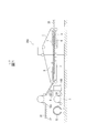
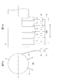
- FIG. 1 is a schematic side view showing a double facer of a corrugating machine according to an embodiment of the present invention and its vicinity.
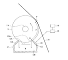
- FIG. 2 is a schematic diagram showing the configuration of the humidifier according to the embodiment of the present invention.
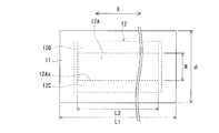
- FIG. 3 is a schematic plan view for explaining the relationship between the size of the liquid application roll (water application roll) and the opening of the chamber.
- FIG. 4 is a schematic diagram when the relative position of the chamber with respect to the liquid application roll is adjusted by the gap adjustment mechanism.
- FIG. 5 is a schematic side view for explaining a range in which the blade for water scraping that can be set defined by the positional relationship between the liquid application roll and the chamber is provided.
- 6A and 6B are schematic views showing the chamber blade together with the liquid application roll, in which FIG.
- FIG. 6A is a cross-sectional view and FIG. 6B is a front view seen from a direction perpendicular thereto.
- 7A and 7B are schematic views showing a doctor blade together with a liquid application roll, in which FIG. 7A is a cross-sectional view, and FIG. 7B is a side view as seen from a direction perpendicular thereto.
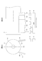
- FIG. 8 is a schematic diagram showing the positional relationship between the two for explaining the limit of the position of the chamber relative to the liquid application roll.
- FIG. 1 is a schematic side view showing a double facer of a corrugating machine according to this embodiment and its vicinity.
- the double facer 200 manufactures a double-faced cardboard 35 by bonding a front liner paper 34 to a single-faced cardboard 31 manufactured by a single facer (not shown). Therefore, starch paste (hereinafter referred to as “glue”) is formed on the corrugated top portion 32a of the core paper 32 of the single-sided cardboard 31 while conveying the single-sided cardboard 31 supplied from the single facer in one direction (from left to right in FIG. 1).
- glue starch paste
- the front liner paper 34 is bonded through
- the front liner paper 34 is heated by the preheater 1 prior to the bonding of the single-sided cardboard 31 and the front liner paper 34, and the humidifying device ( Heating water is applied at 100, which will be described in detail later.
- the front liner paper 34 is fed out from the base paper roll 33 mounted on the mill roll stand and preheated by the preheater 1.
- the preheated front liner paper 34 is humidified by the humidifier 100 and then introduced into the double facer 200.
- the double facer 200 includes a hot plate group 2 that forms a travel path of the single-sided cardboard 31 and the front liner paper 34, and the single-sided cardboard paper 31 and the front liner paper 34 are overlapped to run on the hot plate group 2.
- heating steam is supplied to the hollow portion of the hot plate group 2, and the upper surface of each hot plate is heated to 180 ° C., for example.
- An upper conveyor 3 and a lower conveyor 4 that sandwich and convey a double-sided cardboard 35 formed by laminating a single-sided cardboard 31 and a front liner paper 34 above the hot-plate group 2 and downstream of the hot-plate group 2. Is arranged.
- a pressurizing device 5 that pressurizes the back surface of the upper conveyor 3 by an air pressurizing device or a weight roll and thus presses the single-sided cardboard 31 and the front liner paper 34 from above is provided on the upper part of the hot plate group 2.
- a lower roll group 6 that supports the lower conveyor 4 from the back surface, and an upper weight roll group 7 disposed on the back surface of the upper conveyor 3 on the downstream side of the pressurizing device 5 are provided.
- the single-sided cardboard 31 and the front liner paper 34 introduced between the hot plate group 2 and the pressure device 5 of the double facer 200 were applied to the top 32 a of the core paper 32 of the single-sided cardboard 31 by the gluing device 8. It is placed in a state of being joined via the raw starch solution, and is sandwiched and conveyed between the upper conveyor 3 and the lower conveyor 4. Then, the raw starch liquid is gelatinized by the heat from the front liner paper 34 that receives the temperature while running while sliding in contact with the hot plate group 2, and the front liner paper 34 is made by the adhesive force. Is bonded to the core paper 32 to form a double-sided cardboard 35. The formed double-sided cardboard 35 is transported by the upper conveyor 3 and the lower conveyor 4 and is transported to the next process.
- the raw starch solution is applied to the top 32a of the core paper 32, and the front liner paper 34 is bonded to each top 32a.
- the front liner paper 34 contains appropriate moisture at the time of bonding together with the application of “pressing force” to the bonding portion and the “heating time” of a certain level or more. It is important to keep it humid.
- a humidifier 100 is disposed downstream of the preheater 1 and upstream of the double facer 200.
- the front liner paper 34 is heated to a predetermined temperature by the preheater 1. This is because the starch paste applied to the top 32a of the core paper 32 by the gluing device 8 is gelled by raising the temperature when the core paper 32 of the single-sided cardboard 31 and the front liner paper 34 are bonded together, This is because, in the double facer 200, the core paper 32 and the front liner paper 34 are satisfactorily bonded to each other.
- the moisture content of the front liner paper 34 is reduced by heating in the preheater 1, the moisture content of the front liner paper 34 should be maintained at the optimum moisture content (about 3 to 6% by weight) for bonding. Becomes difficult.
- the front liner paper 34 it is desirable to apply moisture to the front liner paper 34 and humidify it appropriately.
- moisture when moisture is applied for humidification, if the temperature of the moisture to be applied is low, the temperature of the front liner paper 34 is lower than the temperature required for bonding. Therefore, the water used for humidification is heated so that the temperature of the front liner paper 34 at the time of bonding becomes optimum (specifically, it will be described in detail later).
- the heated water for humidification is also referred to as heated water.
- the heating of the front liner paper 34 by the preheater 1 is performed by adjusting the position of an adjustment roll (not shown) arranged in parallel with the axis of the roll forming the preheater 1 on the upstream side and the downstream side of the preheater 1. Is going. That is, the contact area (lap angle) of the front liner paper 34 with respect to the preheater 1 is adjusted by moving the adjustment roll in the circumferential direction at equal intervals with respect to the peripheral surface of the preheater 1. As a result, the heating amount supplied from the preheater 1 to the front liner paper 34 can be adjusted. Incidentally, the heating amount increases as the wrap angle increases. Further, the wrap angle (heating amount) is adjusted to be a predetermined value based on the heat capacity defined by the weight of the front liner paper 34 or the like.
- FIG. 2 is a schematic diagram showing the configuration of the humidifier according to the present embodiment, and is a diagram showing in detail the configuration of the humidifier 100 shown as a block in FIG.
- the humidifying device 100 includes a watering roll (liquid applying roll) 11 and a chamber 12.
- the front liner paper 34 heated by the preheater 1 is brought into contact with the peripheral surface of the watering roll 11, the heated water adhering to the peripheral surface of the watering roll 11 is applied to the front liner paper 34.
- the watering roll 11 is in a vertically downward rotational phase, and its peripheral surface comes into contact with heated water inside the chamber 12 vertically below the rotating shaft 11A via the opening 12A.
- the peripheral surface of the watering roll 11 is flat, for example, and is subjected to metal (chrome) plating. Moreover, you may form a recessed part in the surrounding surface of the watering roll 11 by engraving.
- the amount of heated water applied is adjusted.
- the front liner paper 34 that has passed through the preheater 1 is guided by the guide rolls 15 ⁇ / b> A, 15 ⁇ / b> B, and 15 ⁇ / b> C, and is conveyed toward the double facer 200 in a state where moisture (heated water) is applied by contact with the watering roll 11.
- the amount of heated water applied may be adjusted by moving the guide rolls 15B and 15C to change the contact area (wrap angle) of the front liner paper 34 to the watering roll 11.
- the chamber 12 has opening members 12C and 12D.
- the opening members 12C and 12D are opposed to each other on the downstream side and the upstream side in the rotation direction of the watering roll 11, and are extended in the axial direction of the rotation shaft 11A. Two sides facing each other are defined. Heated water is supplied to the internal space 12B of the chamber 12 communicated via the opening 12A.
- the heated water is stored in the water tank 16, pumped up from the water tank 16 by the pump 17 driven to rotate by the motor 25, and supplied to the internal space 12 ⁇ / b> B through the supply path 13 ⁇ / b> A of the liquid path 13 as described above.
- the heated water in the internal space 12B of the chamber 12 is pressed against the peripheral surface of the watering roll 11 with a predetermined pressure through the opening 12A. Further, the heated water overflowing outside the chamber 12 through the gap between the opening 12 ⁇ / b> A of the chamber 12 and the watering roll 11 is stored in a pan 18 disposed below the chamber 12. That is, the liquid path 13 in the present embodiment has a heated water supply path 13A from the water tank 16 to the chamber 12, and a heated water recovery path 13B from the pan 18 to the water tank 16, and both paths 13A, The liquid path 13 is formed as a circulation path of heated water by 13B.
- the discharge pressure of the pump 17 in the present embodiment is controlled according to the rotation speed of the motor 25.
- the rotation speed of the motor 25 is controlled by a command from the control device 19.
- the pressure of the heated water in the chamber 12 is adjusted.
- Such pressure adjustment of the heating water can also be realized by controlling the supply pressure with a pressure adjusting valve (not shown) while keeping the rotation speed of the pump 17 constant.
- the water tank 16 is provided with a temperature sensor 20 that detects the temperature of the heated water in the water tank 16 and a heater 22 that heats the heated water in the water tank 16.
- the temperature sensor 20 and the heater 22 are respectively provided in the water tank 16. Soaked in heated water.
- the temperature of the heated water in the water tank 16 (in other words, the temperature of the heated water supplied to the chamber 12 via the supply path 13A) is based on the temperature detected by the temperature sensor 20, and the temperature controller 21 is connected to the AC power supply AC and the heater 22.
- the control is performed by turning on / off the switch SW1 interposed between them (turning on / off the power supply to the heater 22).
- the control signal for the switch SW1 output from the temperature controller 21 includes a temperature command value indicating the set temperature of the heated water in the water tank 16 output from the control device 19, and a real-time temperature detection value detected by the temperature sensor 20. And is generated based on the result of comparing. That is, if the temperature command value is higher than the temperature detection value by a predetermined temperature, the switch SW1 is turned on and the heater 22 is turned on. If the temperature command value is lower than the temperature detection value by a predetermined temperature, the switch SW1 is turned off and the heater 22 is turned on. In this way, the temperature of the heated water is maintained within a certain range from the set temperature.
- the temperature of the heated water stored in the water tank 16 is the surface liner paper 34 between the preheater 1 and the watering roll 11 (after being heated by the preheater 1 and before being heated by the watering roll 11). It is determined based on the temperature. This is when the front liner paper 34 is coated with heating water by the watering roll 11 and then bonded to the top 32a of the core paper 32 of the single-sided cardboard 31 with the double facer 200 (see FIG. 1; the same applies hereinafter). This is because the surface temperature of the front liner paper 34 is controlled so that the bonding is performed at an appropriate temperature in consideration of the gelatinization temperature of the starch paste.
- the temperature sensor 23 detects the surface temperature of the front liner paper 34 on the downstream side of the preheater 1 and the upstream side of the watering roll 11, that is, between the preheater 1 and the watering roll 11. Is arranged.
- the temperature sensor 23 sends temperature information indicating the detected surface temperature of the front liner paper 34 to the control device 19.
- the control device 19 has a temperature so that the temperature of the front liner paper 34 becomes an appropriate temperature when being bonded to the single-sided cardboard 31.
- the temperature command value for the controller 21 is determined.
- the temperature of the heated water is set to 90 ° C. or higher so that the temperature of the front liner paper 34 preheated by the preheater 1 can be maintained.
- the rotating peripheral speed of the watering roll 11 in this embodiment is controlled by an inverter-driven motor 26. As the rotating peripheral speed of the watering roll 11 increases, the amount of heated water applied to the front liner paper 34 also increases. However, if the rotating peripheral speed is too high, the surface of the water film on the peripheral surface of the watering roll 11 will be reduced. There is a case where the surface liner paper 34 is roughed to cause uneven humidification. Therefore, in the present embodiment, the surface liner paper 34 can be uniformly humidified without roughening the surface of the water film on the peripheral surface of the watering roll 11, and a water film having an appropriate thickness is formed on the surface liner paper 34.
- a set value for the rotational peripheral speed is determined so that the front liner paper 34 can be appropriately humidified.
- the set value is stored in the control device 19 and is output from the control device 19 to the speed controller 24 as a rotation command value.
- the speed controller 24 converts the voltage of the AC power supply AC into a voltage corresponding to the rotation command value, and supplies it to the inverter-driven motor 26.
- the motor 26 is rotationally driven at a rotational speed based on the rotation command value output from the control device 19.
- the setting value of the rotational peripheral speed of the watering roll 11 is obtained in advance by experiment or the like so that the water film surface of the peripheral surface of the watering roll 11 is not roughened. do it.
- the heat dissipation from the heated water held in the chamber 12 is suppressed as much as possible, and the temperature of the heated water in the chamber 12 It is devised to be kept at a predetermined temperature.
- FIG. 3 is a schematic plan view for explaining the relationship between the size of the watering roll 11 and the opening 12 ⁇ / b> A of the chamber 12.
- opening length the length L2 of the opening 12A in the axial direction of the watering roll 11
- roll length the length L1 in the coaxial direction of the watering roll 11
- opening width the length W (hereinafter referred to as opening width) W in the direction orthogonal to the axial length of the opening 12A is smaller than the diameter (hereinafter referred to as roll diameter) ⁇ of the watering roll 11. It is formed.
- the opening 12A of the chamber 12 is covered with the watering roll 11, thereby suppressing the heat dissipation from the heating water from the opening 12A.
- the opening width W is formed to be smaller than the roll diameter ⁇ (opening width W ⁇ roll diameter ⁇ )
- the opening length L2 is formed to be shorter than the roll length L1. If (opening length L2 ⁇ roll length L1), at least if the opening width W is smaller than the roll diameter ⁇ (opening width W ⁇ roll diameter ⁇ ), the effect of suppressing the heat dissipation of the heating water can be obtained.
- the opening width W is made smaller than the roll diameter ⁇ and the opening length L2 is made shorter than the roll length L1, it is naturally possible to obtain a better heat dissipation suppression effect. it can.
- the opening length L2 is preferably set to a dimension larger than the entire width of the liner paper 34 so that moisture can be applied to the entire width of the liner paper 34.
- the gap is preferably as small as possible, but it is defined by the amount of humidification between the four sides defining the opening 12A and one side 12Aa of the opening 12A on the most downstream side in the roll rotation direction. It is necessary to provide a slight gap. Thus, the most effective heat retention can be ensured by ensuring that the remaining three sides defining the opening 12A are in contact with the peripheral surface of the watering roll 11 while ensuring the gap. It is important that the gap between the watering roll 11 does not roughen the surface of the water film of the watering roll 11. In addition, what is necessary is just to determine the optimal value (setting value) of the clearance gap between the watering roll 11 and the opening part 12A by experiment.
- a seal member is provided on three sides excluding one side 12Aa formed by the opening member 12C, and the chamber 12 is in contact with the watering roll 11 via the seal member. In this case, even better heat retention can be ensured.
- a gap between the watering roll 11 and the opening 12 ⁇ / b> A of the chamber 12 is provided by providing a gap adjusting mechanism 27 that adjusts the relative position of the chamber 12 with respect to the watering roll 11. It can also be configured to be able to adjust.
- the structure which adjusts the position of the chamber 12 with respect to the watering roll 11 by moving the chamber 12 linearly in the vertical direction by the gap adjusting mechanism 27 is exemplified.
- the gap adjusting mechanism 27 can be used to adjust the gap between the opening 12A and the watering roll 11 to a desired size.
- the amount of water to be attached to the peripheral surface of the roll 11 can be arbitrarily set, and as a result, the humidification amount for the front liner paper 34 can be arbitrarily set.
- the operation of the gap adjustment mechanism 27 is controlled by the control device 19.
- the thickness of the water film on the peripheral surface of the watering roll 11, and consequently the surface liner paper 34 is appropriately scraped off by heating water adhering to the peripheral surface of the watering roll 11.
- the amount of heating water applied is adjusted. That is, the scraping of the heated water adhering to the peripheral surface of the watering roll 11 is performed after the watering roll 11 comes into contact with the heated water in the chamber 12 along with its rotation and causes the heated water to adhere to the peripheral surface. And before applying to the front liner paper 34.
- the scraping of the heated water is a range between “the inner space 12 ⁇ / b> B of the chamber 12” and “the contact point P between the watering roll 11 and the front liner paper 34”. This can be done with ⁇ .
- the opening member that forms the opening 12A of the chamber 12 and extends in the axial direction X of the watering roll 11 A blade (chamber blade) can also be formed using the opening member 12C on the downstream side in the rotation direction of the watering roll 11 among the 12C and 12D (the opening member 12C is hereinafter also referred to as the blade 12C).
- the lower end portion of the blade 12C is rotatably supported by the hinge portion 12E.
- the gap between the tip of the blade 12C and the peripheral surface of the watering roll 11 is easily adjusted, and the heated water is scraped from the peripheral surface of the watering roll 11.
- the amount to be taken can be set as appropriate.
- a hinge portion (not shown) is provided at the base end portion of the blade 14 so that the amount of rotation is adjusted and the peripheral surface of the watering roll 11 is provided.
- the amount of scraping of the heated water from the peripheral surface of the watering roll 11 can be appropriately set.
- the blades 12C and 14 as described above may be configured such that a plurality of blades 12C, 14 narrow in the axial direction X of the watering roll 11 are arranged in the axial direction X. Examples of such blades 12C and 14 will be described with reference to FIGS. 6A, 6B, 7A, and 7B.
- FIGS. 6A and 6B are schematic views showing a blade formed as a chamber blade together with a watering roll, in which FIG. 6A is a cross-sectional view and FIG. 6B is a front view as seen from a direction perpendicular thereto.
- the blade drive mechanism 28 individually adjusts the rotation amount (tilt) of each blade 12C, so that the tip of each blade 12C is appropriately adjusted with respect to the peripheral surface of the watering roll 11.
- the gap between the blade 12 and the peripheral surface of the watering roll 11 is adjusted for each blade 12C.
- Such individual adjustment makes it possible to change the distribution of the amount of scraping water with respect to the axial direction X of the watering roll 11.
- water films can be formed on the peripheral surface of the watering roll 11 with different film thicknesses depending on the position in the axial direction X.
- the surface liner paper 34 is humidified with water films of different thicknesses, so that the bonding conditions are optimized and the distribution of the amount of humidification of the surface liner paper 34 in the axial direction X is changed to optimize the bonding conditions.
- the warpage of the double-sided cardboard 35 in the axial direction X can be controlled.
- the blade 12C is a member constituting a part of the chamber 12, it is a member having a relatively large predetermined thickness. That is, even when each blade 12C is rotated independently, as shown by a broken line in FIG. 6A, the blades 12C adjacent in the axial direction X are partially overlapped by the thickness thereof, and each of the plurality of blades 12C is overlapped. A gap is prevented from being generated between them, and leakage of heated water through the gap is prevented.
- FIGS. 7A and 7B are schematic views showing blades (doctor blades) 14 formed separately from the chamber together with a watering roll.
- FIG. 7A is a cross-sectional view
- FIG. 7B is viewed from a direction perpendicular thereto. It is a front view.
- a plurality of narrow blades 14 are provided side by side in the axial direction X.
- Each blade 14 is individually rotated by a blade driving mechanism 29 around a hinge (not shown) at the base end.
- blade 14 is contacted / separated suitably with respect to the surrounding surface of the watering roll 11, and each clearance gap between each blade 14 and the surrounding surface of the watering roll 11 can be adjusted separately.
- each blade 14 is configured separately from the chamber 12 and is disposed downstream of the chamber 12 in the roll rotation direction. For this reason, each blade 14 will be arrange
- Both the blade 12C and the blade 14 adjust the gap with the watering roll 11 by changing the rotation amount with the base end portion as the rotation center and adjusting the inclination, thereby adjusting the watering roll 11.
- the quantity of the heating water made to adhere to the surrounding surface of this may be controlled, it does not restrict to this.
- the blade 12C and the blade 14 are formed so as to be able to advance and retreat in the respective longitudinal directions, the gap between the tips of the blades 12C and 14 and the peripheral surface of the watering roll 11 can be adjusted. Can be achieved.
- the control device 19 controls the blade drive mechanisms 28 and 29 that adjust the gap between the watering roll 11 and the blades 12C and 14.
- the watering roll 11 can function as a lid of the opening 12A.
- the airtightness of the internal space 12B of the chamber 12 can be enhanced, and the heated water heated to a predetermined temperature can be held in the internal space 12B having a high airtightness.
- the heat dissipation in the heating water in the chamber 12 can be suppressed as much as possible and maintained at a predetermined temperature. Therefore, the front liner paper 34 can be humidified with heated water having a predetermined temperature that takes into account the gelatinization temperature of the starch paste.
- the temperature of the front liner paper 34 can be set to a temperature suitable for the gelatinization of the glue, and the water content of the front liner paper 34 can be set to a water content suitable for the penetration of the glue.
- the single-sided cardboard 31 (core paper 32) and the front liner paper 34 can be bonded well.
- the humidifier 100 as described above is provided downstream of the preheater 1, so that the temperature and moisture content of the front liner paper 34 heated by the preheater 1 are bonded to each other by glue. It can be suitable, and the bonding of the front liner paper 34 to the core paper 32 on the downstream side of the humidifying device 100 under the optimum conditions can be realized.
- the present invention is not limited to this.
- the arrangement of the chamber 12 may be a position shifted from the vertical lower position of the watering roll 11 to some extent on the downstream side or the upstream side in the roll rotation direction (counterclockwise direction in this example).
- an example of the limit of the range allowed as the position of the chamber 12 is shown by a two-dot chain line in FIG.
- the chamber 12 has the opening member 12C on the downstream side (right side in the drawing) with respect to the rotation direction of the watering roll 11 with respect to the vertical center line VC, and the opening member on the upstream side (left side in the drawing).
- Each of the outer surfaces of 12D is a surface (including a vertical surface) that is inclined obliquely downward from the horizontal plane toward the outside of the chamber 12 (as it is separated from the watering roll 11 if expressed differently). Need to be. This is because the water droplets W1 and W2 that have exuded from the chamber 12 between the watering roll 11 and the upper end portions of the opening members 12C and 12D are dropped by their own weight and are discharged.
- the outer surface of the opening member 12C and the opening member 12D is a surface (including a horizontal surface) inclined obliquely upward toward the outside of the chamber 12, the watering roll 11 and the opening member 12C. , 12D, water exuding from the chamber 12 is accumulated as water droplets W1, W2, and in some cases, the accumulated water droplets W1, W2 are formed on the peripheral surface of the watering roll 11. If the surface liner paper 34 is scattered or scattered on the front liner paper 34 (see FIG. 2), an adverse situation such as an adverse effect on the front liner paper 34 occurs. Therefore, the position of the chamber 12 indicated by a two-dot chain line in FIG. 8 is the limit position of the allowable range.
- the outer surface of the opening member 12C and the opening member 12D refers to a surface of the opening member 12C and the opening member 12D that faces the outside of the chamber 12, that is, a surface opposite to the inner surface facing the internal space 12B. .
- the liquid path 13 for supplying water to the chamber 12 is a circulation path having the supply path 13A and the recovery path 13B including the pan 18, but in principle, only the supply path 13A may be used.
- the circulation path by configuring the circulation path, the heated water overflowing from the chamber 12 can be reused, and wasteful consumption of the heated water can be prevented.
- the temperature sensor 23 may be disposed on the downstream side of the watering roll 11 as long as it is upstream of the double facer 200.
- information on the temperature detected by the temperature sensor 23 is returned to the control device 19, where the temperature of the front liner paper 34 at the time of pasting by the double facer 200 is a predetermined temperature in consideration of the gelling temperature of the starch paste. This is because the temperature of the heated water is controlled so that
- the mounting position of the temperature sensor 20 for detecting the temperature of the heated water and the heater 22 for heating the heated water can detect the temperature of the heated water supplied to the chamber 12 such as in the chamber 12 or the liquid path 13. If it is a position which can be heated and a position where heated water can be heated, there is no particular limitation on the place. However, the mounting position of the temperature sensor 20 is optimal as long as the inside of the chamber 12 has solved the problem of installation space. This is because the temperature of the heated water immediately before adhering to the front liner paper 34 can be directly managed by the temperature sensor 20.
- a surfactant may be added to the heated water.
- the heated water can be easily soaked into the front liner paper 34. Thereby, the wetting time until heated water permeates sufficiently can be shortened, and the necessary penetration depth of the paste can be obtained in a short time.
- the back liner paper and the core paper are pasted together by glue even in the production of the single-sided cardboard 31 in the single facer, so that it is provided on the upstream side of the single facer.
- a similar humidifier 100 may be disposed between the preheater and the single facer. Thereby, favorable pasting with back liner paper and core paper can be performed.
- the humidifier 100 can be substituted for the preheater 1. In this case, heating by the preheater 1 can be stopped. In the case of a corrugating machine dedicated to lightweight liner paper, the preheater can be omitted by using the humidifier 100 as a preheater.
Landscapes
- Engineering & Computer Science (AREA)
- Mechanical Engineering (AREA)
- Chemical & Material Sciences (AREA)
- Ceramic Engineering (AREA)
- Machines For Manufacturing Corrugated Board In Mechanical Paper-Making Processes (AREA)
Abstract
Provided are a humidifying device and a corrugating machine whereby release of heat from heated water can be suppressed as much as possible and a liner paper can be humidified at the appropriate temperature. A humidifying device (100) for humidifying a surface liner paper (34) affixed to a core paper via a starch glue applied to apexes of waves in the core paper, wherein the humidifying device (100) has: a liquid application roller (11) for applying heated water to the surface liner paper (34), the liquid application roller (11) being provided downstream from a preheater (11) for heating the surface liner paper (34) prior to the affixing; and a chamber (12) disposed facing the peripheral face of the liquid application roller (11) and provided with an internal space (12B) to which the heated water is supplied; the chamber (12) furthermore has an opening (12A) for supplying the heated water to the peripheral face of the liquid application roller (11), and the chamber (12) is formed so that the length of the opening (12A) in the direction orthogonal to the axial direction of the liquid application roller (11) is less than the diameter of the liquid application roller (11).
Description
本発明は、プレヒータにより加熱された後、かつ中芯紙に貼合される前にライナ紙を加湿する加湿装置、およびこの加湿装置を使用したコルゲートマシンに関する。
The present invention relates to a humidifier that humidifies liner paper after being heated by a preheater and before being bonded to a core paper, and a corrugating machine using the humidifier.
コルゲートマシンと称される段ボール製造装置の製造ラインは、一般に段ボール紙の原料になる表ライナ紙の原紙や裏ライナ紙の原紙や中芯原紙の原紙ロールを装備するミルロールスタンドと、コルゲートマシンに向けて連続的に段ボール原紙を供給するための紙継ぎ装置としてのスプライサと、該ミルロールスタンドから繰り出された中芯紙を波形に成形するとともに波形の頂部に塗布した糊を介して裏ライナ紙と貼り合わせ、片面段ボール紙を製造するシングルフェーサと、該シングルフェーサで製造された片面段ボール紙における前記波形の残りの頂部に塗布した糊を介して表ライナ紙と貼り合わせることにより両面段ボール紙を製造するダブルフェーサとを備えている。
The corrugated machine manufacturing line, called the corrugating machine, has a mill roll stand equipped with a base liner paper, a front liner base paper, a core liner base paper roll, and a corrugated machine. Splicer as a splicing device for continuously supplying the corrugated cardboard toward the back, and liner paper that forms the core paper fed from the mill roll stand into a corrugated shape and paste applied to the top of the corrugated shape A single facer for producing a single-sided corrugated cardboard, and a double-faced corrugated cardboard by adhering to a front liner paper via glue applied to the remaining top of the corrugated sheet in the single-sided cardboard produced by the single facer And a double facer for producing paper.
この種のコルゲートマシンにおいては、シングルフェーサやダブルフェーサにおける中芯紙に対するライナ紙の貼合に先立ちライナ紙をプレヒータで加熱している。これは、ライナ紙の貼合作業において、ライナ紙が良好に貼合されるよう所定のライナ紙温度に予熱するためである。そこで、一般的には、ロール状のプレヒータの周面(加熱面)にライナ紙を接触させて搬送させることにより加熱している。ここで、ライナ紙がロール状のプレヒータに接触している時間が長い、すなわちライナ紙のプレヒータに対する巻付け角(ラップ角)が大きいほどライナ紙に与えられる加熱量は増加する。そこで、ラップ角の調整によりライナ紙の加熱量を設定している。ラップ角は、プレヒータの上流側と下流側にプレヒータと平行に配設されたロールをプレヒータの周面に対して等間隔で円周方向に移動させて、ライナ紙のプレヒータに対する接触面積を調整して設定する。
In this type of corrugating machine, the liner paper is heated with a preheater prior to the lamination of the liner paper to the core paper in a single facer or double facer. This is because in the liner paper laminating operation, the liner paper is preheated to a predetermined liner paper temperature so that the liner paper is satisfactorily pasted. Therefore, in general, heating is performed by bringing liner paper into contact with the peripheral surface (heating surface) of a roll-shaped preheater and transporting it. Here, the amount of heating applied to the liner paper increases as the time during which the liner paper is in contact with the roll-shaped preheater is longer, that is, the winding angle (wrap angle) of the liner paper with respect to the preheater is larger. Therefore, the heating amount of the liner paper is set by adjusting the wrap angle. The wrap angle adjusts the contact area of liner paper to the preheater by moving the rolls arranged in parallel with the preheater on the upstream side and downstream side of the preheater in the circumferential direction at equal intervals with respect to the peripheral surface of the preheater. To set.
従来技術においては、単位面積当たりの重量が大きい重量ライナ紙を貼合する場合も、ライナ紙の熱容量増大を補完するためにラップ角を増大させ、加熱量を増大させることによりライナ紙が良好に貼合される所定のライナ紙温度に予熱している。
In the prior art, even when laminating heavy liner paper with a large weight per unit area, the liner paper is improved by increasing the wrap angle and increasing the heating amount in order to complement the increase in heat capacity of the liner paper. Preheated to the predetermined liner paper temperature to be bonded.
糊が浸透し易いライナ紙の水分は、一般に3~6重量%であるが、上述の如くプレヒータにより加熱熱量を増大させると、同時にライナ紙(特に表層)の水分を減少させてしまう。この水分の減少が、単位時間当たりに糊がライナ紙に浸透する深さである浸透深さを減少させるという問題を生起する。かかる問題を回避するためには、濡れ時間を長くして浸透時間を稼ぐべくライナ紙の搬送速度を落とさざるを得ない。しかしながら、この場合には、段ボールの生産効率の低下を招来する。
The moisture of the liner paper that easily penetrates the paste is generally 3 to 6% by weight. However, as described above, when the amount of heating heat is increased by the preheater, the moisture of the liner paper (especially the surface layer) is simultaneously reduced. This reduction in moisture creates a problem of reducing the penetration depth, which is the depth at which glue permeates the liner paper per unit time. In order to avoid such a problem, it is necessary to reduce the liner paper conveyance speed in order to increase the wetting time and increase the permeation time. In this case, however, the production efficiency of the cardboard is reduced.
特許文献1(図1参照)には、プレヒータで加熱後のライナ紙に適度な水分を含有させ、下流のダブルフェーサにおける中芯紙との貼合が良好に行われるよう、水付けロールをプレヒータの下流に配設したコルゲートマシンが開示されている。また、特許文献2(図8参照)には、ダブルフェーサのヒーティング部とクーリング部との間にライナ紙の加湿用の水付けロール装置を配設したものが開示されている。ただ、特許文献2は、クーリング部に搬送されるライナ紙を水付けロールで適度に加湿することによりライナ紙の幅方向に関する反りを防止することを目的とするものである。
In Patent Document 1 (see FIG. 1), an appropriate amount of moisture is contained in the liner paper heated by the preheater, and a watering roll is attached to the preheater so that the downstream double facer can be well bonded to the core paper. A corrugating machine disposed downstream is disclosed. Patent Document 2 (see FIG. 8) discloses a watering roll device for humidifying liner paper disposed between a heating portion and a cooling portion of a double facer. However, Patent Document 2 aims to prevent warping in the width direction of the liner paper by appropriately humidifying the liner paper conveyed to the cooling unit with a watering roll.
上記特許文献1における水付けロールは、パンに貯留された水に浸漬して外周面に水膜を形成し、接触するライナ紙の表面にこの水膜を塗布する。ここで、ライナ紙に塗布した水によりライナ紙の温度が低下するので、パンには所定温度に加熱した水(加熱水)が供給される。水の温度が低いと、ライナ紙の温度が低下し、次工程の貼合作業に必要なライナ紙温度を保持できず、貼合不良となる場合が発生するので、これを回避するためである。
The watering roll in Patent Document 1 is immersed in water stored in a pan to form a water film on the outer peripheral surface, and this water film is applied to the surface of the liner paper that comes into contact. Here, since the temperature of the liner paper is lowered by the water applied to the liner paper, water heated to a predetermined temperature (heated water) is supplied to the pan. If the temperature of the water is low, the temperature of the liner paper is lowered, the liner paper temperature necessary for the pasting operation in the next process cannot be maintained, and a case of poor bonding may occur, so this is avoided. .
しかしながら、特許文献1において、加湿用の加熱水を貯留しているパンは上部全体(以下、開放部という)が開放されているので、パンと水付けロールとの間に大きな隙間が形成される。この結果、加熱水の熱が前記開放部から放熱してしまい、加熱水を所定の高温(例えば90℃)に保持することが難しかった。
However, in Patent Document 1, since the entire upper part (hereinafter referred to as an open part) of the pan storing the humidified heating water is opened, a large gap is formed between the pan and the watering roll. . As a result, the heat of the heating water is dissipated from the opening, and it is difficult to maintain the heating water at a predetermined high temperature (for example, 90 ° C.).
一方、特許文献2は、ライナ紙の幅方向に関する反りを防止することを目的とするものであるため、ライナ紙の加湿装置は開示されているものの、ライナ紙を加湿するための水の温度管理に関しては改善の余地がある。
On the other hand, since Patent Document 2 aims to prevent warping in the width direction of liner paper, although a humidifying device for liner paper is disclosed, temperature control of water for humidifying liner paper is disclosed. There is room for improvement.
本発明は、上記従来技術に鑑み、加熱水からの熱の放出を可及的に抑制し、適切な温度でライナ紙の加湿を行うことができる加湿装置およびコルゲートマシンを提供することを目的とする。
An object of the present invention is to provide a humidifying device and a corrugating machine that can suppress the release of heat from heated water as much as possible and can humidify liner paper at an appropriate temperature. To do.
上記目的を達成する本発明は、
1) 一方向へ搬送され、波形に成形された中芯紙の前記波形の頂部に塗布された糊を介して前記中芯紙に貼合されるライナ紙を加湿する加湿装置であって、
前記貼合に先立ち前記ライナ紙を加熱するプレヒータの下流に配設され、前記ライナ紙に加熱した液体を塗布する液付けロールと、
前記液付ロールの周面に対向して配置され、前記液体が供給される内部空間を備えたチャンバとを有するとともに、
前記チャンバは、前記内部空間と連通して前記液体を前記液付けロールの前記周面に供給するための開口部を有しており、前記開口部の前記液付けロールの軸方向に直交する方向の長さが、前記液付けロールの直径よりも小さいことを特徴とする加湿装置である。 The present invention for achieving the above object
1) A humidifying device that humidifies a liner paper that is conveyed in one direction and is bonded to the core paper through glue applied to the top of the corrugated core paper that has been formed into a waveform,
A liquid application roll disposed downstream of a pre-heater for heating the liner paper prior to the bonding, and applying a heated liquid to the liner paper;
A chamber having an internal space that is disposed opposite to the peripheral surface of the liquid roll and is supplied with the liquid;
The chamber has an opening that communicates with the internal space and supplies the liquid to the peripheral surface of the liquid application roll, and a direction orthogonal to the axial direction of the liquid application roll of the opening Is a humidifying device characterized in that the length of the humidifier is smaller than the diameter of the liquid application roll.
かかる本発明によれば、加湿用の加熱した液体を密閉性が高いチャンバの内部空間で保持するとともに、液体はチャンバの開口部を介して液付けロールに接触され、さらに開口部の液付けロールの軸に直交する方向の幅方向長さが、液付けロールの直径よりも小さいので、実質的に液付けロールを開口部の蓋として機能させることができる。
According to the present invention, the heated liquid for humidification is held in the interior space of the chamber having high hermeticity, the liquid is brought into contact with the liquid application roll through the opening of the chamber, and the liquid application roll in the opening is further provided. Since the length in the width direction in the direction orthogonal to the axis is smaller than the diameter of the liquid application roll, the liquid application roll can substantially function as a lid for the opening.
2) ここで、前記チャンバを、前記液付けロールの軸心の鉛直下方に配設するのが望ましい。チャンバに付着した液滴が、自重により自然に落下して排斥され易くなるからである。
2) Here, it is desirable to arrange the chamber vertically below the axis of the liquid application roll. This is because the droplets adhering to the chamber are easily dropped by their own weight and easily discharged.
3) さらに、前記チャンバは、前記開口部を形成する前記軸方向に伸びる開口部材の外側面が、水平面よりも斜め下方に傾斜するのが望ましい。前記面に付着した液滴が自重により自然に落下して排斥されるからである。
3) Further, in the chamber, it is preferable that an outer surface of the opening member extending in the axial direction forming the opening is inclined obliquely downward from a horizontal plane. This is because the droplets adhering to the surface naturally fall by the dead weight and are discarded.
4) 前記内部空間と、前記液付けロールと前記ライナ紙との接触点との間に配設され、液付けロールの表面に付着した前記液体を掻き取るブレードとを備えるとともに、前記液付けロールと前記ブレードとの少なくとも一方の作動を制御して前記ライナ紙に塗布する前記液体の量を調節する制御手段を備えているのが望ましい。液付けロールの周面に付着する液体の量ひいては前記ライナ紙に付与する液体量を調整することができるからである。
4) Provided between the internal space and a contact point between the liquid application roll and the liner paper, and provided with a blade for scraping the liquid adhering to the surface of the liquid application roll, and the liquid application roll It is desirable to provide control means for controlling the operation of at least one of the blade and the blade to adjust the amount of the liquid applied to the liner paper. This is because the amount of liquid adhering to the peripheral surface of the liquid application roll and thus the amount of liquid applied to the liner paper can be adjusted.
5) 前記ブレードは、前記軸方向に複数並設されるとともに、各ブレードが前記液付けロールの表面に対して接離する方向に駆動するブレード駆動機構を有するのが望ましい。液付けロールのロール周面の軸方向に関する液体の付着量に分布を持たせることができるからである。
5) It is preferable that a plurality of the blades are arranged in parallel in the axial direction and have a blade driving mechanism that drives each blade in a direction in which the blade comes in contact with and separates from the surface of the liquid application roll. This is because it is possible to give a distribution to the amount of liquid attached in the axial direction of the roll peripheral surface of the liquid application roll.
6) 前記ブレードを、前記チャンバよりも前記液付けロールの回転方向下流側に配設するのが望ましい。ライナ紙に液体を付与する前に、液付けロールの周面に付着する液体の量を調整することができるからである。
6) It is desirable that the blade is disposed downstream of the chamber in the rotation direction of the liquid application roll. This is because the amount of liquid adhering to the peripheral surface of the liquid application roll can be adjusted before applying the liquid to the liner paper.
7) さらに、前記ブレードを、前記チャンバの前記開口部を形成する前記開口部材により構成されたものであることが望ましい。チャンバの開口部材にブレード機能を兼用させることができるからである。
7) Furthermore, it is desirable that the blade is constituted by the opening member that forms the opening of the chamber. This is because the opening member of the chamber can also serve as a blade function.
8) 前記チャンバの前記開口部と前記液付けロールの周面との隙間を調整する隙間調整機構を備えるのが望ましい。前記隙間を容易に調整することができるからである。
8) It is desirable to provide a clearance adjustment mechanism that adjusts the clearance between the opening of the chamber and the peripheral surface of the liquid application roll. This is because the gap can be easily adjusted.
9) 前記液付けロールを回転するモータを備え、前記制御手段は、前記モータの回転速度を制御するのが望ましい。モータの回転速度を制御することでライナ紙に塗布する液体の量を容易に制御し得るからである。
9) It is desirable that a motor for rotating the liquid application roll is provided, and the control means controls the rotational speed of the motor. This is because the amount of liquid applied to the liner paper can be easily controlled by controlling the rotation speed of the motor.
10) 前記チャンバ内に液体を供給する液体経路を有するとともに、前記液体経路に前記液体の加熱手段を介設するのが望ましい。放熱による液体の温度低下を相殺することができるからである。
10) It is desirable to have a liquid path for supplying a liquid into the chamber and to provide a heating means for the liquid in the liquid path. This is because the temperature drop of the liquid due to heat dissipation can be offset.
11) 前記加熱手段は、前記チャンバ内に配設されるのが望ましい。ライナ紙に塗布される直前で液体を加熱することができるので、放熱による温度低下を抑えることができるからである。
11) The heating means is preferably disposed in the chamber. This is because the liquid can be heated immediately before being applied to the liner paper, so that a temperature drop due to heat radiation can be suppressed.
12) 前記液体経路に前記液体の温度を計測する温度センサを備え、前記温度センサの検出結果に基づいて前記加熱手段の出力を制御するのが望ましい。液体を所定温度に保持することを容易に行い得るからである。
12) It is desirable to provide a temperature sensor for measuring the temperature of the liquid in the liquid path, and to control the output of the heating means based on the detection result of the temperature sensor. This is because it is possible to easily maintain the liquid at a predetermined temperature.
13) 前記チャンバの下方に前記液体を受けるパンを配設するのが望ましい。チャンバから溢れた液体やブレードで掻きとられた液体を回収することができるからである。
13) It is desirable to arrange a pan for receiving the liquid below the chamber. This is because the liquid overflowing from the chamber and the liquid scraped by the blade can be recovered.
14) 前記液体経路は、前記チャンバ内に前記液体を供給する供給経路と、前記パンに貯留された前記液体を、前記供給経路へ戻す回収経路とを備えた循環路であることが望ましい。加熱水を再利用し、水の昇温効率を高めることができるからである。つまり、前記パンに貯留された前記液体は、一度は加熱されているので、ある程度の温度を有しており、少ない加熱量で所定温度まで昇温することができる。
14) The liquid path is preferably a circulation path having a supply path for supplying the liquid into the chamber and a recovery path for returning the liquid stored in the pan to the supply path. This is because the heating water can be reused to increase the water heating efficiency. That is, since the liquid stored in the pan has been heated once, it has a certain temperature and can be raised to a predetermined temperature with a small heating amount.
15) 前記糊は澱粉糊であり、前記液体の温度を90℃以上とするのが望ましい。プレヒータで予熱されたライナ紙温度を保持し得るからである。
15) The paste is starch paste, and the temperature of the liquid is desirably 90 ° C or higher. This is because the liner paper temperature preheated by the preheater can be maintained.
16) 他の発明は、
一方向へ搬送され、波形に成形された中芯紙の前記波形の頂部に塗布された糊を介して前記中芯紙に貼合されるシート状のライナ紙を前記貼合に先立ち加熱するプレヒータの下流に上記1)~15)のいずれか一つに記載する加湿装置が配設されたことを特徴とするコルゲートマシンである。 16) Other inventions
A preheater that heats a sheet-like liner paper that is transported in one direction and is bonded to the core paper via glue applied to the top of the corrugated core paper that is formed into a waveform. The corrugating machine is characterized in that the humidifier described in any one of 1) to 15) above is disposed downstream of the machine.
本発明によれば、上述の如き加湿装置をプレヒータの下流に有するので、プレヒータで加熱したライナ紙の温度を最適貼合温度に保持しつつ、ライナ紙の最適水分量を得ることにより、最適条件での前記貼合を実現することができる。ここで加湿装置の加熱液体はチャンバに保持されているので、温度管理が容易になり、ライナ紙の適正温度の維持を容易に実現し得る。
According to the present invention, since the humidifier as described above is provided downstream of the preheater, the optimum condition is obtained by obtaining the optimum moisture content of the liner paper while maintaining the temperature of the liner paper heated by the preheater at the optimum bonding temperature. The above-mentioned pasting can be realized. Here, since the heating liquid of the humidifier is held in the chamber, temperature management becomes easy, and maintenance of the appropriate temperature of the liner paper can be easily realized.
本発明の加湿装置によれば、加湿用の加熱した液体を密閉性が高いチャンバの内部空間で保持するとともに、液体はチャンバの開口部を介して液付けロールに供給され、さらに開口部の液付けロールの軸方向に直交する方向の長さが液付けロールの直径よりも小さいので、実質的に液付けロールを開口部の蓋として機能させることができる。この結果、チャンバ内に保持されている液体からの放熱を可及的に抑制し、この液体によって適切な温度でライナ紙の加湿を行うことができる。
また、これにより、熱容量が大きい重量ライナ紙であっても、搬送速度を落とすことなく、ライナ紙の温度を貼合に適切な温度とすることができ、良好な貼合強度を得ることができる。 According to the humidifying device of the present invention, the heated liquid for humidification is held in the internal space of the chamber having high hermeticity, and the liquid is supplied to the liquid application roll through the opening of the chamber. Since the length in the direction orthogonal to the axial direction of the application roll is smaller than the diameter of the application roll, the application roll can substantially function as a lid for the opening. As a result, heat release from the liquid held in the chamber is suppressed as much as possible, and the liner paper can be humidified at an appropriate temperature by this liquid.
Moreover, even if it is a heavy liner paper with a large heat capacity, the temperature of the liner paper can be set to an appropriate temperature for bonding without reducing the conveying speed, and good bonding strength can be obtained. .
また、本発明のコルゲートマシンによれば、上述の如き加湿装置をプレヒータの下流に有するので、プレヒータで加熱したライナ紙の温度を最適貼合温度に保持しつつ、ライナ紙の最適水分量を得ることにより、最適条件での貼合を実現することができる。ここで加湿装置の加熱液体はチャンバに保持されているので、温度保持が容易になり、ライナ紙の適正温度の維持を容易に実現し得る。
Further, according to the corrugating machine of the present invention, since the humidifier as described above is provided downstream of the preheater, the optimum moisture content of the liner paper is obtained while maintaining the temperature of the liner paper heated by the preheater at the optimum bonding temperature. By this, it is possible to realize bonding under optimum conditions. Here, since the heating liquid of the humidifier is held in the chamber, the temperature can be easily maintained, and the maintenance of the appropriate temperature of the liner paper can be easily realized.
以下、図面を参照して、本発明の実施の形態について説明する。
なお、以下に示す各実施形態はあくまでも例示に過ぎず、以下の各実施形態で明示しない種々の変形や技術の適用を排除する意図はない。以下の各実施形態の各構成は、それらの趣旨を逸脱しない範囲で種々変形して実施することができるとともに、必要に応じて取捨選択することができ、あるいは適宜組み合わせることが可能である。 Embodiments of the present invention will be described below with reference to the drawings.
Note that each embodiment described below is merely an example, and there is no intention to exclude various modifications and technical applications that are not explicitly described in the following embodiments. Each configuration of each of the following embodiments can be implemented with various modifications without departing from the spirit thereof, can be selected as necessary, or can be appropriately combined.
[1.ダブルフェーサ及びその周辺の構成]
図1は本実施形態に係るコルゲートマシンのダブルフェーサおよびその近傍部分を抽出して示す模式的な側面図である。図1に示すように、ダブルフェーサ200は、シングルフェーサ(図示せず)で製造された片面段ボール31に表ライナ紙34を貼合して、両面段ボール35を製造する。このため、シングルフェーサから供給される片面段ボール31を一方向(図1中の左側から右側)へ搬送しつつ片面段ボール31の中芯紙32の波形の頂部32aに澱粉糊(以下、糊ともいう)を介して表ライナ紙34を貼合している。
ここで、本実施形態におけるコルゲートマシンでは、片面段ボール31と表ライナ紙34との貼合に先立ち、表ライナ紙34をプレヒータ1で加熱するとともに、加熱した表ライナ紙34に対して加湿装置(構造に関しては後に詳述する)100で加熱水を塗布している。
付言すると、表ライナ紙34は、ミルロールスタンドに装着された原紙ロール33から繰り出され、プレヒータ1で予備加熱される。予備加熱された表ライナ紙34は、加湿装置100で加湿された後、ダブルフェーサ200に導入される。 [1. Double facer and surrounding structure]
FIG. 1 is a schematic side view showing a double facer of a corrugating machine according to this embodiment and its vicinity. As shown in FIG. 1, thedouble facer 200 manufactures a double-faced cardboard 35 by bonding a front liner paper 34 to a single-faced cardboard 31 manufactured by a single facer (not shown). Therefore, starch paste (hereinafter referred to as “glue”) is formed on the corrugated top portion 32a of the core paper 32 of the single-sided cardboard 31 while conveying the single-sided cardboard 31 supplied from the single facer in one direction (from left to right in FIG. 1). The front liner paper 34 is bonded through
Here, in the corrugating machine according to the present embodiment, thefront liner paper 34 is heated by the preheater 1 prior to the bonding of the single-sided cardboard 31 and the front liner paper 34, and the humidifying device ( Heating water is applied at 100, which will be described in detail later.
In other words, thefront liner paper 34 is fed out from the base paper roll 33 mounted on the mill roll stand and preheated by the preheater 1. The preheated front liner paper 34 is humidified by the humidifier 100 and then introduced into the double facer 200.
図1は本実施形態に係るコルゲートマシンのダブルフェーサおよびその近傍部分を抽出して示す模式的な側面図である。図1に示すように、ダブルフェーサ200は、シングルフェーサ(図示せず)で製造された片面段ボール31に表ライナ紙34を貼合して、両面段ボール35を製造する。このため、シングルフェーサから供給される片面段ボール31を一方向(図1中の左側から右側)へ搬送しつつ片面段ボール31の中芯紙32の波形の頂部32aに澱粉糊(以下、糊ともいう)を介して表ライナ紙34を貼合している。
ここで、本実施形態におけるコルゲートマシンでは、片面段ボール31と表ライナ紙34との貼合に先立ち、表ライナ紙34をプレヒータ1で加熱するとともに、加熱した表ライナ紙34に対して加湿装置(構造に関しては後に詳述する)100で加熱水を塗布している。
付言すると、表ライナ紙34は、ミルロールスタンドに装着された原紙ロール33から繰り出され、プレヒータ1で予備加熱される。予備加熱された表ライナ紙34は、加湿装置100で加湿された後、ダブルフェーサ200に導入される。 [1. Double facer and surrounding structure]
FIG. 1 is a schematic side view showing a double facer of a corrugating machine according to this embodiment and its vicinity. As shown in FIG. 1, the
Here, in the corrugating machine according to the present embodiment, the
In other words, the
ダブルフェーサ200は、片面段ボール31および表ライナ紙34の走行路を形成する熱板群2を備え、片面段ボール紙31と表ライナ紙34とが重ね合わされて熱板群2上を走行する。ここで、熱板群2の中空部には加熱蒸気が供給され、各熱板上面は、例えば180℃に加熱される。熱板群2の上方および熱板群2の下流側には、片面段ボール31と表ライナ紙34とが貼合されて形成された両面段ボール35を挟持して搬送する上コンベア3および下コンベア4が配設されている。また、熱板群2の上部には、エア加圧装置またはウェイトロール等によって上コンベア3の背面を加圧し、ひいては片面段ボール31および表ライナ紙34を上方から加圧する加圧装置5が設けられている。さらに、下コンベア4を背面から支持する下ロール群6と、加圧装置5の下流側で上コンベア3の背面に配置された上ウェイトロール群7とが設けられている。
The double facer 200 includes a hot plate group 2 that forms a travel path of the single-sided cardboard 31 and the front liner paper 34, and the single-sided cardboard paper 31 and the front liner paper 34 are overlapped to run on the hot plate group 2. Here, heating steam is supplied to the hollow portion of the hot plate group 2, and the upper surface of each hot plate is heated to 180 ° C., for example. An upper conveyor 3 and a lower conveyor 4 that sandwich and convey a double-sided cardboard 35 formed by laminating a single-sided cardboard 31 and a front liner paper 34 above the hot-plate group 2 and downstream of the hot-plate group 2. Is arranged. In addition, a pressurizing device 5 that pressurizes the back surface of the upper conveyor 3 by an air pressurizing device or a weight roll and thus presses the single-sided cardboard 31 and the front liner paper 34 from above is provided on the upper part of the hot plate group 2. ing. Furthermore, a lower roll group 6 that supports the lower conveyor 4 from the back surface, and an upper weight roll group 7 disposed on the back surface of the upper conveyor 3 on the downstream side of the pressurizing device 5 are provided.
ダブルフェーサ200の熱板群2と加圧装置5との間に導入された片面段ボール31と表ライナ紙34とは、糊付装置8で片面段ボール31の中芯紙32の頂部32aに塗布された生澱粉液を介して接合された状態に置かれ、上コンベア3と下コンベア4とで挟持されて搬送される。そして、熱板群2に接触摺動しながら走行しつつ受熱して昇温される表ライナ紙34からの熱によって生澱粉液が糊化(ゲル化)され、その接着力で表ライナ紙34が中芯紙32に貼合され、両面段ボール35が形成される。形成された両面段ボール35は、上コンベア3および下コンベア4により搬送されて次工程に搬送される。
The single-sided cardboard 31 and the front liner paper 34 introduced between the hot plate group 2 and the pressure device 5 of the double facer 200 were applied to the top 32 a of the core paper 32 of the single-sided cardboard 31 by the gluing device 8. It is placed in a state of being joined via the raw starch solution, and is sandwiched and conveyed between the upper conveyor 3 and the lower conveyor 4. Then, the raw starch liquid is gelatinized by the heat from the front liner paper 34 that receives the temperature while running while sliding in contact with the hot plate group 2, and the front liner paper 34 is made by the adhesive force. Is bonded to the core paper 32 to form a double-sided cardboard 35. The formed double-sided cardboard 35 is transported by the upper conveyor 3 and the lower conveyor 4 and is transported to the next process.
このように当該コルゲートマシンにおけるダブルフェーサ200では中芯紙32の頂部32aに生澱粉液が塗布され、各頂部32aに表ライナ紙34が貼合される。この場合の貼合力を良好に発揮させるためには、貼合部に対する「加圧力」の付与と一定以上の「加熱時間」とともに、表ライナ紙34が貼合時に適度の水分を含有するように加湿しておくことが肝要である。かかる加湿を行うため、プレヒータ1の下流側でダブルフェーサ200の上流側には、加湿装置100が配設してある。
Thus, in the double facer 200 in the corrugating machine, the raw starch solution is applied to the top 32a of the core paper 32, and the front liner paper 34 is bonded to each top 32a. In order to satisfactorily exert the bonding force in this case, the front liner paper 34 contains appropriate moisture at the time of bonding together with the application of “pressing force” to the bonding portion and the “heating time” of a certain level or more. It is important to keep it humid. In order to perform such humidification, a humidifier 100 is disposed downstream of the preheater 1 and upstream of the double facer 200.
本実施形態においては、表ライナ紙34がプレヒータ1で所定の温度に加熱される。これは、糊付装置8で中芯紙32の頂部32aに塗布した澱粉糊を、片面段ボール31の中芯紙32と表ライナ紙34との貼合せの際に昇温させてゲル化させ、ダブルフェーサ200において片面段ボール31の中芯紙32と表ライナ紙34とを良好に貼合させるためである。一方、プレヒータ1における加熱により表ライナ紙34の含有水分量が減少するので、表ライナ紙34の含有水分量を、貼合にとって最適な含有水分量(3~6重量%程度)に保持することが困難になる。そこで、表ライナ紙34に水分を付与して適度に加湿するのが望ましい。
しかしながら、加湿のために水分を付与した場合には、付与する水分の温度が低いと表ライナ紙34の温度が、貼合に必要な温度よりも低下してしまう。そこで、貼合時の表ライナ紙34の温度が最適になるように、加湿に使用する水を加熱している(具体的には後に詳述する)。以下、加熱された加湿用の水を加熱水ともいう。 In the present embodiment, thefront liner paper 34 is heated to a predetermined temperature by the preheater 1. This is because the starch paste applied to the top 32a of the core paper 32 by the gluing device 8 is gelled by raising the temperature when the core paper 32 of the single-sided cardboard 31 and the front liner paper 34 are bonded together, This is because, in the double facer 200, the core paper 32 and the front liner paper 34 are satisfactorily bonded to each other. On the other hand, since the moisture content of the front liner paper 34 is reduced by heating in the preheater 1, the moisture content of the front liner paper 34 should be maintained at the optimum moisture content (about 3 to 6% by weight) for bonding. Becomes difficult. Therefore, it is desirable to apply moisture to the front liner paper 34 and humidify it appropriately.
However, when moisture is applied for humidification, if the temperature of the moisture to be applied is low, the temperature of thefront liner paper 34 is lower than the temperature required for bonding. Therefore, the water used for humidification is heated so that the temperature of the front liner paper 34 at the time of bonding becomes optimum (specifically, it will be described in detail later). Hereinafter, the heated water for humidification is also referred to as heated water.
しかしながら、加湿のために水分を付与した場合には、付与する水分の温度が低いと表ライナ紙34の温度が、貼合に必要な温度よりも低下してしまう。そこで、貼合時の表ライナ紙34の温度が最適になるように、加湿に使用する水を加熱している(具体的には後に詳述する)。以下、加熱された加湿用の水を加熱水ともいう。 In the present embodiment, the
However, when moisture is applied for humidification, if the temperature of the moisture to be applied is low, the temperature of the
ここで、プレヒータ1による表ライナ紙34の加熱は、プレヒータ1の上流側と下流側とでプレヒータ1を形成するロールの軸と平行に配設された図示しない調整ロールの位置を調整することにより行っている。すなわち、調整ロールをプレヒータ1の周面に対して等間隔で円周方向に移動させて表ライナ紙34のプレヒータ1に対する接触面積(ラップ角)を調整している。このことでプレヒータ1から表ライナ紙34に供給される加熱量を調整することができる。ちなみに、ラップ角が大きいほど加熱量が増大する。また、ラップ角(加熱量)は表ライナ紙34の重量等に規定される熱容量に基づき所定の値になるように調整される。
Here, the heating of the front liner paper 34 by the preheater 1 is performed by adjusting the position of an adjustment roll (not shown) arranged in parallel with the axis of the roll forming the preheater 1 on the upstream side and the downstream side of the preheater 1. Is going. That is, the contact area (lap angle) of the front liner paper 34 with respect to the preheater 1 is adjusted by moving the adjustment roll in the circumferential direction at equal intervals with respect to the peripheral surface of the preheater 1. As a result, the heating amount supplied from the preheater 1 to the front liner paper 34 can be adjusted. Incidentally, the heating amount increases as the wrap angle increases. Further, the wrap angle (heating amount) is adjusted to be a predetermined value based on the heat capacity defined by the weight of the front liner paper 34 or the like.
[2.加湿装置の構成]
図2は、本実施形態に係る加湿装置の構成を示す模式図であり、図1においてブロックで示す加湿装置100の構成を詳細に示す図である。図2に示すように、加湿装置100は水付けロール(液付けロール)11とチャンバ12とを有している。プレヒータ1で加熱された表ライナ紙34を水付けロール11の周面に当接させることにより水付けロール11の周面に付着している加熱水が表ライナ紙34に塗布される。水付けロール11は、鉛直下方の回転位相で、その周面が、その回転軸11Aの鉛直下方のチャンバ12の内部の加熱水に開口部12Aを介して接触するようになっている。なお、水付けロール11の周面は、例えば平坦であり金属(クロム)メッキが施されている。また、水付けロール11の周面に、彫刻により凹部を形成してもよい。 [2. Humidifier configuration]
FIG. 2 is a schematic diagram showing the configuration of the humidifier according to the present embodiment, and is a diagram showing in detail the configuration of thehumidifier 100 shown as a block in FIG. As shown in FIG. 2, the humidifying device 100 includes a watering roll (liquid applying roll) 11 and a chamber 12. When the front liner paper 34 heated by the preheater 1 is brought into contact with the peripheral surface of the watering roll 11, the heated water adhering to the peripheral surface of the watering roll 11 is applied to the front liner paper 34. The watering roll 11 is in a vertically downward rotational phase, and its peripheral surface comes into contact with heated water inside the chamber 12 vertically below the rotating shaft 11A via the opening 12A. The peripheral surface of the watering roll 11 is flat, for example, and is subjected to metal (chrome) plating. Moreover, you may form a recessed part in the surrounding surface of the watering roll 11 by engraving.
図2は、本実施形態に係る加湿装置の構成を示す模式図であり、図1においてブロックで示す加湿装置100の構成を詳細に示す図である。図2に示すように、加湿装置100は水付けロール(液付けロール)11とチャンバ12とを有している。プレヒータ1で加熱された表ライナ紙34を水付けロール11の周面に当接させることにより水付けロール11の周面に付着している加熱水が表ライナ紙34に塗布される。水付けロール11は、鉛直下方の回転位相で、その周面が、その回転軸11Aの鉛直下方のチャンバ12の内部の加熱水に開口部12Aを介して接触するようになっている。なお、水付けロール11の周面は、例えば平坦であり金属(クロム)メッキが施されている。また、水付けロール11の周面に、彫刻により凹部を形成してもよい。 [2. Humidifier configuration]
FIG. 2 is a schematic diagram showing the configuration of the humidifier according to the present embodiment, and is a diagram showing in detail the configuration of the
かくして回転軸11Aの回転(図2では反時計方向への回転)に伴いチャンバ12内の加熱水と接触した水付けロール11の周面に加熱水による水膜が形成され、この水膜(加熱水)を表ライナ紙34に塗布している。ここで、チャンバ12よりも水付けロール11の回転方向(以下、ロール回転方向ともいう)で下流側に位置設定された「表ライナ紙34と水付けロール11との接触箇所P」と、チャンバ12との間にはブレード(ドクターブレード)14が配設してある。このブレード14で水付けロール11の周面に付着する余分な加熱水を適宜掻き取ることにより、水付けロール11の周面の形成される水膜の厚さ、ひいては表ライナ紙34に塗布される加熱水の塗布量を調整している。プレヒータ1を通過した表ライナ紙34は、案内ロール15A,15B,15Cで案内され、水付けロール11との接触により水分(加熱水)を付与された状態でダブルフェーサ200に向けて搬送される。なお、案内ロール15B,15Cを移動させて、水付けロール11への表ライナ紙34の接触面積(ラップ角)を変化させて、加熱水の塗布量を調整してもよい。
Thus, as the rotating shaft 11A rotates (counterclockwise in FIG. 2), a water film is formed on the peripheral surface of the watering roll 11 in contact with the heated water in the chamber 12, and this water film (heated) Water) is applied to the front liner paper 34. Here, the “contact point P between the front liner paper 34 and the watering roll 11” positioned downstream of the chamber 12 in the rotation direction of the watering roll 11 (hereinafter also referred to as the roll rotation direction), and the chamber A blade (doctor blade) 14 is disposed between the blades 12 and 12. By scraping off excessive heated water adhering to the peripheral surface of the watering roll 11 with this blade 14, the thickness of the water film formed on the peripheral surface of the watering roll 11, and consequently, applied to the front liner paper 34. The amount of heated water applied is adjusted. The front liner paper 34 that has passed through the preheater 1 is guided by the guide rolls 15 </ b> A, 15 </ b> B, and 15 </ b> C, and is conveyed toward the double facer 200 in a state where moisture (heated water) is applied by contact with the watering roll 11. Note that the amount of heated water applied may be adjusted by moving the guide rolls 15B and 15C to change the contact area (wrap angle) of the front liner paper 34 to the watering roll 11.
チャンバ12は、開口部材12C,12Dを有している。開口部材12C,12Dは水付けロール11の回転方向に関する下流側と上流側とで相対向するとともに回転軸11Aの軸方向に延伸されており、それぞれの上端で開口部12Aの前記下流側と上流側との相対向する2辺を規定している。開口部12Aを介して連通されているチャンバ12の内部空間12Bには、加熱水が供給される。加熱水は、水槽16内に貯留され、モータ25で回転駆動されるポンプ17により水槽16から汲み上げられるとともに液体経路13の供給経路13Aを介して上述のとおり内部空間12Bに供給される。この結果、チャンバ12の内部空間12Bの加熱水は、開口部12Aを介して所定の圧力で水付けロール11の周面に押し当てられる。
また、チャンバ12の開口部12Aと水付けロール11との間の隙間を介してチャンバ12の外部に溢れた加熱水は、チャンバ12の下方に配設されたパン18に貯留される。すなわち、本実施形態における液体経路13は、水槽16からチャンバ12に至る加熱水の供給径路13Aと、パン18から水槽16に戻る加熱水の回収径路13Bとを有しており、両経路13A,13Bにより液体経路13を加熱水の循環径路として形成している。ここで、本実施形態におけるポンプ17は、モータ25の回転数に応じて吐出圧力が制御される。また、モータ25は制御装置19からの指令によりその回転数が制御される。かくして、チャンバ12内の加熱水の圧力が調整される。かかる加熱水の圧力調整は、ポンプ17の回転数を一定にして圧力調整弁(図示せず)で供給圧力を制御することによっても実現し得る。 Thechamber 12 has opening members 12C and 12D. The opening members 12C and 12D are opposed to each other on the downstream side and the upstream side in the rotation direction of the watering roll 11, and are extended in the axial direction of the rotation shaft 11A. Two sides facing each other are defined. Heated water is supplied to the internal space 12B of the chamber 12 communicated via the opening 12A. The heated water is stored in the water tank 16, pumped up from the water tank 16 by the pump 17 driven to rotate by the motor 25, and supplied to the internal space 12 </ b> B through the supply path 13 </ b> A of the liquid path 13 as described above. As a result, the heated water in the internal space 12B of the chamber 12 is pressed against the peripheral surface of the watering roll 11 with a predetermined pressure through the opening 12A.
Further, the heated water overflowing outside thechamber 12 through the gap between the opening 12 </ b> A of the chamber 12 and the watering roll 11 is stored in a pan 18 disposed below the chamber 12. That is, the liquid path 13 in the present embodiment has a heated water supply path 13A from the water tank 16 to the chamber 12, and a heated water recovery path 13B from the pan 18 to the water tank 16, and both paths 13A, The liquid path 13 is formed as a circulation path of heated water by 13B. Here, the discharge pressure of the pump 17 in the present embodiment is controlled according to the rotation speed of the motor 25. The rotation speed of the motor 25 is controlled by a command from the control device 19. Thus, the pressure of the heated water in the chamber 12 is adjusted. Such pressure adjustment of the heating water can also be realized by controlling the supply pressure with a pressure adjusting valve (not shown) while keeping the rotation speed of the pump 17 constant.
また、チャンバ12の開口部12Aと水付けロール11との間の隙間を介してチャンバ12の外部に溢れた加熱水は、チャンバ12の下方に配設されたパン18に貯留される。すなわち、本実施形態における液体経路13は、水槽16からチャンバ12に至る加熱水の供給径路13Aと、パン18から水槽16に戻る加熱水の回収径路13Bとを有しており、両経路13A,13Bにより液体経路13を加熱水の循環径路として形成している。ここで、本実施形態におけるポンプ17は、モータ25の回転数に応じて吐出圧力が制御される。また、モータ25は制御装置19からの指令によりその回転数が制御される。かくして、チャンバ12内の加熱水の圧力が調整される。かかる加熱水の圧力調整は、ポンプ17の回転数を一定にして圧力調整弁(図示せず)で供給圧力を制御することによっても実現し得る。 The
Further, the heated water overflowing outside the
水槽16には、水槽16内の加熱水の温度を検出する温度センサ20と、水槽16内の加熱水を加熱するヒータ22とが設けられており、温度センサ20及びヒータ22はそれぞれ水槽16内の加熱水に浸漬されている。
水槽16内の加熱水の温度(換言すれば供給経路13Aを介してチャンバ12に供給される加熱水の温度)は、温度センサ20の検出温度に基づき、温度コントローラ21が交流電源ACとヒータ22との間に介在させたスイッチSW1をオン/オフさせること(ヒータ22への通電をオン/オフさせること)により制御する。つまり、温度コントローラ21から出力されるスイッチSW1に対する制御信号は、制御装置19から出力される水槽16内の加熱水の設定温度を表す温度指令値と、温度センサ20が検出するリアルタイムの温度検出値とを比較した結果に基づき生成される。
すなわち、温度指令値が温度検出値よりも所定温度高ければ、スイッチSW1がオンされてヒータ22がオンし、温度指令値が温度検出値よりも所定温度低ければスイッチSW1がオフされてヒータ22がオフし、これにより、加熱水の温度が設定温度から一定範囲内に維持される。 Thewater tank 16 is provided with a temperature sensor 20 that detects the temperature of the heated water in the water tank 16 and a heater 22 that heats the heated water in the water tank 16. The temperature sensor 20 and the heater 22 are respectively provided in the water tank 16. Soaked in heated water.
The temperature of the heated water in the water tank 16 (in other words, the temperature of the heated water supplied to thechamber 12 via the supply path 13A) is based on the temperature detected by the temperature sensor 20, and the temperature controller 21 is connected to the AC power supply AC and the heater 22. The control is performed by turning on / off the switch SW1 interposed between them (turning on / off the power supply to the heater 22). That is, the control signal for the switch SW1 output from the temperature controller 21 includes a temperature command value indicating the set temperature of the heated water in the water tank 16 output from the control device 19, and a real-time temperature detection value detected by the temperature sensor 20. And is generated based on the result of comparing.
That is, if the temperature command value is higher than the temperature detection value by a predetermined temperature, the switch SW1 is turned on and theheater 22 is turned on. If the temperature command value is lower than the temperature detection value by a predetermined temperature, the switch SW1 is turned off and the heater 22 is turned on. In this way, the temperature of the heated water is maintained within a certain range from the set temperature.
水槽16内の加熱水の温度(換言すれば供給経路13Aを介してチャンバ12に供給される加熱水の温度)は、温度センサ20の検出温度に基づき、温度コントローラ21が交流電源ACとヒータ22との間に介在させたスイッチSW1をオン/オフさせること(ヒータ22への通電をオン/オフさせること)により制御する。つまり、温度コントローラ21から出力されるスイッチSW1に対する制御信号は、制御装置19から出力される水槽16内の加熱水の設定温度を表す温度指令値と、温度センサ20が検出するリアルタイムの温度検出値とを比較した結果に基づき生成される。
すなわち、温度指令値が温度検出値よりも所定温度高ければ、スイッチSW1がオンされてヒータ22がオンし、温度指令値が温度検出値よりも所定温度低ければスイッチSW1がオフされてヒータ22がオフし、これにより、加熱水の温度が設定温度から一定範囲内に維持される。 The
The temperature of the heated water in the water tank 16 (in other words, the temperature of the heated water supplied to the
That is, if the temperature command value is higher than the temperature detection value by a predetermined temperature, the switch SW1 is turned on and the
水槽16に貯留される加熱水の温度は、プレヒータ1と水付けロール11との間における(プレヒータ1で加熱された後かつ水付けロール11で加熱水が塗布される前の)表ライナ紙34の温度に基づき決定される。これは、表ライナ紙34が水付けロール11により加熱水を塗布された後、ダブルフェーサ200(図1参照;以下同じ)で片面段ボール31の中芯紙32の頂部32aに貼合される際に、澱粉糊のゲル化温度を加味した適切な温度で貼合が行われるように表ライナ紙34の表面温度を制御するためである。
このため、本実施形態では、プレヒータ1の下流側かつ水付けロール11の上流側で、つまりプレヒータ1と水付けロール11との間で、表ライナ紙34の表面の温度を検出する温度センサ23が配設してある。温度センサ23は、検出した表ライナ紙34の表面温度を表す温度情報を制御装置19に送出する。 The temperature of the heated water stored in thewater tank 16 is the surface liner paper 34 between the preheater 1 and the watering roll 11 (after being heated by the preheater 1 and before being heated by the watering roll 11). It is determined based on the temperature. This is when the front liner paper 34 is coated with heating water by the watering roll 11 and then bonded to the top 32a of the core paper 32 of the single-sided cardboard 31 with the double facer 200 (see FIG. 1; the same applies hereinafter). This is because the surface temperature of the front liner paper 34 is controlled so that the bonding is performed at an appropriate temperature in consideration of the gelatinization temperature of the starch paste.
For this reason, in the present embodiment, thetemperature sensor 23 detects the surface temperature of the front liner paper 34 on the downstream side of the preheater 1 and the upstream side of the watering roll 11, that is, between the preheater 1 and the watering roll 11. Is arranged. The temperature sensor 23 sends temperature information indicating the detected surface temperature of the front liner paper 34 to the control device 19.
このため、本実施形態では、プレヒータ1の下流側かつ水付けロール11の上流側で、つまりプレヒータ1と水付けロール11との間で、表ライナ紙34の表面の温度を検出する温度センサ23が配設してある。温度センサ23は、検出した表ライナ紙34の表面温度を表す温度情報を制御装置19に送出する。 The temperature of the heated water stored in the
For this reason, in the present embodiment, the
制御装置19は、表ライナ紙34が水付けロール11により加熱水を塗布された後でも、表ライナ紙34の温度が片面段ボール31に貼合される際に適切な温度となるように、温度コントローラ21に対する温度指令値を決定している。本実施形態では、プレヒータ1で予熱された表ライナ紙34の温度を保持できるように、加熱水の温度は90℃以上に設定されている。
Even after the front liner paper 34 is coated with heated water by the watering roll 11, the control device 19 has a temperature so that the temperature of the front liner paper 34 becomes an appropriate temperature when being bonded to the single-sided cardboard 31. The temperature command value for the controller 21 is determined. In the present embodiment, the temperature of the heated water is set to 90 ° C. or higher so that the temperature of the front liner paper 34 preheated by the preheater 1 can be maintained.
本実施形態における水付けロール11はインバータ駆動のモータ26でその回転周速が制御される。水付けロール11は、その回転周速が増大するにしたがって表ライナ紙34に対する加熱水の塗布量も増大するが、回転周速が速すぎると、水付けロール11の周面の水膜表面が荒れて表ライナ紙34に対する加湿むらを生起する場合がある。そこで、本実施形態では、水付けロール11の周面の水膜表面が荒れることなく表ライナ紙34の均一な加湿を実現でき、しかも表ライナ紙34に適切な厚さの水膜を形成して表ライナ紙34の適切な加湿を行うことができるように回転周速に関する設定値を定めている。かかる設定値は制御装置19に記憶されており、制御装置19から回転指令値として速度コントローラ24に出力される。速度コントローラ24では交流電源ACの電圧を回転指令値に対応する電圧に変換してインバータ駆動のモータ26に供給する。この結果、モータ26は制御装置19が出力する回転指令値に基づく回転数で回転駆動される。なお、上記水付けロール11の回転周速の設定値は、水付けロール11の周面の水膜表面が荒れることのない周速を実験等により予め求めておき、この周速を設定値とすればよい。
The rotating peripheral speed of the watering roll 11 in this embodiment is controlled by an inverter-driven motor 26. As the rotating peripheral speed of the watering roll 11 increases, the amount of heated water applied to the front liner paper 34 also increases. However, if the rotating peripheral speed is too high, the surface of the water film on the peripheral surface of the watering roll 11 will be reduced. There is a case where the surface liner paper 34 is roughed to cause uneven humidification. Therefore, in the present embodiment, the surface liner paper 34 can be uniformly humidified without roughening the surface of the water film on the peripheral surface of the watering roll 11, and a water film having an appropriate thickness is formed on the surface liner paper 34. Thus, a set value for the rotational peripheral speed is determined so that the front liner paper 34 can be appropriately humidified. The set value is stored in the control device 19 and is output from the control device 19 to the speed controller 24 as a rotation command value. The speed controller 24 converts the voltage of the AC power supply AC into a voltage corresponding to the rotation command value, and supplies it to the inverter-driven motor 26. As a result, the motor 26 is rotationally driven at a rotational speed based on the rotation command value output from the control device 19. In addition, the setting value of the rotational peripheral speed of the watering roll 11 is obtained in advance by experiment or the like so that the water film surface of the peripheral surface of the watering roll 11 is not roughened. do it.
本実施形態では、加湿する加熱水の温度等による加湿条件を変動させないため、チャンバ12内に保持されている加熱水からの放熱を可及的に抑制してチャンバ12内の加熱水の温度が所定温度に保持されるよう工夫している。
In this embodiment, in order not to change the humidification conditions depending on the temperature of the heated water to be humidified, etc., the heat dissipation from the heated water held in the chamber 12 is suppressed as much as possible, and the temperature of the heated water in the chamber 12 It is devised to be kept at a predetermined temperature.
以下この点について図3を参照して説明する。図3は水付けロール11とチャンバ12の開口部12Aとの大きさの関係を説明するための模式的な平面図である。
図3に示すように、水付けロール11の軸方向に関する開口部12Aの長さ(以下、開口長という)L2が、水付けロール11の同軸方向に関する長さ(以下、ロール長という)L1よりも小さく、同時に開口部12Aの前記軸方向長さに直交する方向に関する長さ(以下、開口幅という)Wが、水付けロール11の直径(以下、ロール径という)φよりも小さくなるように形成してある。この結果、チャンバ12の開口部12Aは水付けロール11で蓋をされた状態となり、これにより開口部12Aからの加熱水の放熱を抑制することができる。ここで本実施形態では、開口幅Wをロール径φよりも小さくなるように形成し(開口幅W<ロール径φ)、かつ、開口長L2をロール長L1よりも短くなるように形成したが(開口長L2<ロール長L1)、少なくとも開口幅Wがロール径φよりも小さくなっていれば(開口幅W<ロール径φ)、加熱水の放熱を抑止する効果は得られる。ただ、本実施形態の如く、開口幅Wをロール径φよりも小さく形成すると同時に開口長L2をロール長L1よりも短く形成した方が、当然、より良好な熱の放散抑止効果を得ることができる。
なお、開口長さL2は、ライナ紙34の全幅に水分を付与できるよう、ライナ紙34の全幅よりも大きな寸法に設定されていることが好ましい。 Hereinafter, this point will be described with reference to FIG. FIG. 3 is a schematic plan view for explaining the relationship between the size of the wateringroll 11 and the opening 12 </ b> A of the chamber 12.
As shown in FIG. 3, the length L2 of theopening 12A in the axial direction of the watering roll 11 (hereinafter referred to as opening length) L2 is greater than the length L1 in the coaxial direction of the watering roll 11 (hereinafter referred to as roll length). At the same time so that the length W (hereinafter referred to as opening width) W in the direction orthogonal to the axial length of the opening 12A is smaller than the diameter (hereinafter referred to as roll diameter) φ of the watering roll 11. It is formed. As a result, the opening 12A of the chamber 12 is covered with the watering roll 11, thereby suppressing the heat dissipation from the heating water from the opening 12A. In this embodiment, the opening width W is formed to be smaller than the roll diameter φ (opening width W <roll diameter φ), and the opening length L2 is formed to be shorter than the roll length L1. If (opening length L2 <roll length L1), at least if the opening width W is smaller than the roll diameter φ (opening width W <roll diameter φ), the effect of suppressing the heat dissipation of the heating water can be obtained. However, as in this embodiment, when the opening width W is made smaller than the roll diameter φ and the opening length L2 is made shorter than the roll length L1, it is naturally possible to obtain a better heat dissipation suppression effect. it can.
The opening length L2 is preferably set to a dimension larger than the entire width of theliner paper 34 so that moisture can be applied to the entire width of the liner paper 34.
図3に示すように、水付けロール11の軸方向に関する開口部12Aの長さ(以下、開口長という)L2が、水付けロール11の同軸方向に関する長さ(以下、ロール長という)L1よりも小さく、同時に開口部12Aの前記軸方向長さに直交する方向に関する長さ(以下、開口幅という)Wが、水付けロール11の直径(以下、ロール径という)φよりも小さくなるように形成してある。この結果、チャンバ12の開口部12Aは水付けロール11で蓋をされた状態となり、これにより開口部12Aからの加熱水の放熱を抑制することができる。ここで本実施形態では、開口幅Wをロール径φよりも小さくなるように形成し(開口幅W<ロール径φ)、かつ、開口長L2をロール長L1よりも短くなるように形成したが(開口長L2<ロール長L1)、少なくとも開口幅Wがロール径φよりも小さくなっていれば(開口幅W<ロール径φ)、加熱水の放熱を抑止する効果は得られる。ただ、本実施形態の如く、開口幅Wをロール径φよりも小さく形成すると同時に開口長L2をロール長L1よりも短く形成した方が、当然、より良好な熱の放散抑止効果を得ることができる。
なお、開口長さL2は、ライナ紙34の全幅に水分を付与できるよう、ライナ紙34の全幅よりも大きな寸法に設定されていることが好ましい。 Hereinafter, this point will be described with reference to FIG. FIG. 3 is a schematic plan view for explaining the relationship between the size of the watering
As shown in FIG. 3, the length L2 of the
The opening length L2 is preferably set to a dimension larger than the entire width of the
チャンバ12の開口部12Aからの放熱を考える場合、開口部12Aと水付けロール11との間の隙間を考慮することも肝要である。放熱を抑制する観点からは、この隙間は小さいほど望ましいが、開口部12Aを規定する4辺の内、ロール回転方向に関して最下流側の開口部12Aの一辺12Aaとの間には加湿量によって規定される僅かな隙間を設けておく必要がある。そこで、前記隙間を確保して開口部12Aを規定する残りの3辺を水付けロール11の周面に当接させる構成とすることで、最も効果的な保温性を確保し得る。水付けロール11との間の前記隙間は、水付けロール11の水膜表面が荒れないようにすることが肝要である。なお、水付けロール11と開口部12Aとの間の隙間の最適値(設定値)は、実験等により決定しておけばよい。
When considering heat radiation from the opening 12A of the chamber 12, it is also important to consider the gap between the opening 12A and the watering roll 11. From the viewpoint of suppressing heat dissipation, the gap is preferably as small as possible, but it is defined by the amount of humidification between the four sides defining the opening 12A and one side 12Aa of the opening 12A on the most downstream side in the roll rotation direction. It is necessary to provide a slight gap. Thus, the most effective heat retention can be ensured by ensuring that the remaining three sides defining the opening 12A are in contact with the peripheral surface of the watering roll 11 while ensuring the gap. It is important that the gap between the watering roll 11 does not roughen the surface of the water film of the watering roll 11. In addition, what is necessary is just to determine the optimal value (setting value) of the clearance gap between the watering roll 11 and the opening part 12A by experiment.
開口部12Aを規定する4辺の内、開口部材12Cで形成する1辺12Aaを除く3辺についてはシール部材を配設し、このシール部材を介して水付けロール11にチャンバ12が当接するように構成しても良く、この場合には、さらに良好な保温性を確保し得る。
Of the four sides that define the opening 12A, a seal member is provided on three sides excluding one side 12Aa formed by the opening member 12C, and the chamber 12 is in contact with the watering roll 11 via the seal member. In this case, even better heat retention can be ensured.
ここで、図4に示すように、水付けロール11に対するチャンバ12の相対的な位置を調整する隙間調整機構27を設けることにより、水付けロール11とチャンバ12の開口部12Aとの間の隙間を調整できるように構成することもできる。チャンバ12を隙間調整機構27にて鉛直方向に直線移動することにより水付けロール11に対してチャンバ12の位置を調整する構造が例示される。このように隙間調整機構27を設けることは必須ではないが、隙間調整機構27を設けることで開口部12Aと水付けロール11との隙間を所望の大きさに調整することが可能となり、水付けロール11の周面に付着させる水量を任意に設定することができ、ひいては表ライナ紙34に対する加湿量を任意に設定することができる。なお、隙間調整機構27の作動は制御装置19により制御される。
Here, as shown in FIG. 4, a gap between the watering roll 11 and the opening 12 </ b> A of the chamber 12 is provided by providing a gap adjusting mechanism 27 that adjusts the relative position of the chamber 12 with respect to the watering roll 11. It can also be configured to be able to adjust. The structure which adjusts the position of the chamber 12 with respect to the watering roll 11 by moving the chamber 12 linearly in the vertical direction by the gap adjusting mechanism 27 is exemplified. Although it is not essential to provide the gap adjusting mechanism 27 as described above, the gap adjusting mechanism 27 can be used to adjust the gap between the opening 12A and the watering roll 11 to a desired size. The amount of water to be attached to the peripheral surface of the roll 11 can be arbitrarily set, and as a result, the humidification amount for the front liner paper 34 can be arbitrarily set. The operation of the gap adjustment mechanism 27 is controlled by the control device 19.
また、前述の如く本実施形態では、水付けロール11の周面に付着する加熱水を適宜掻き取ることにより、水付けロール11の周面の水膜の厚さ、ひいては表ライナ紙34への加熱水の塗布量を調整するようになっている。すなわち、水付けロール11の周面に付着する加熱水の掻き取りは、水付けロール11がその回転に伴いチャンバ12内の加熱水に接触してその周面に加熱水を付着させた後で、かつ表ライナ紙34に塗布する前に行えば良い。詳細には、図5に示すように、かかる加熱水の掻き取りは、「チャンバ12の内部空間12B」と、「水付けロール11と表ライナ紙34との接触箇所P」との間の範囲θで行えば良い。
Further, as described above, in the present embodiment, the thickness of the water film on the peripheral surface of the watering roll 11, and consequently the surface liner paper 34, is appropriately scraped off by heating water adhering to the peripheral surface of the watering roll 11. The amount of heating water applied is adjusted. That is, the scraping of the heated water adhering to the peripheral surface of the watering roll 11 is performed after the watering roll 11 comes into contact with the heated water in the chamber 12 along with its rotation and causes the heated water to adhere to the peripheral surface. And before applying to the front liner paper 34. Specifically, as shown in FIG. 5, the scraping of the heated water is a range between “the inner space 12 </ b> B of the chamber 12” and “the contact point P between the watering roll 11 and the front liner paper 34”. This can be done with θ.
したがって、上記のようにブレード(ドクターブレード)14(図2参照)に代えて、図5に示すように、チャンバ12の開口部12Aを形成するとともに水付けロール11の軸方向Xに伸びる開口部材12C,12Dの内、水付けロール11の回転方向下流側の開口部材12Cを利用してブレード(チャンバブレード)を形成することもできる(そこで、以下、開口部材12Cをブレード12Cともいう)。ブレード12Cはその下端部をヒンジ部12Eに回動可能に支持されている。ブレード12Cを回動して傾きを適宜変更することで、容易にブレード12Cの先端と水付けロール11の周面との隙間を調整して、水付けロール11の周面からの加熱水の掻き取り量を適宜設定することができる。
Therefore, instead of the blade (doctor blade) 14 (see FIG. 2) as described above, as shown in FIG. 5, the opening member that forms the opening 12A of the chamber 12 and extends in the axial direction X of the watering roll 11 A blade (chamber blade) can also be formed using the opening member 12C on the downstream side in the rotation direction of the watering roll 11 among the 12C and 12D (the opening member 12C is hereinafter also referred to as the blade 12C). The lower end portion of the blade 12C is rotatably supported by the hinge portion 12E. By rotating the blade 12C and changing the inclination as appropriate, the gap between the tip of the blade 12C and the peripheral surface of the watering roll 11 is easily adjusted, and the heated water is scraped from the peripheral surface of the watering roll 11. The amount to be taken can be set as appropriate.
もちろん、上述の如くドクターブレードであるブレード14を使用する場合もこのブレード14の基端部にヒンジ部(図示せず)を設けることで、その回動量を調節して水付けロール11の周面との間の隙間を適宜調整して、水付けロール11の周面からの加熱水の掻き取り量を適宜設定することができる。
Of course, when using the blade 14 which is a doctor blade as described above, a hinge portion (not shown) is provided at the base end portion of the blade 14 so that the amount of rotation is adjusted and the peripheral surface of the watering roll 11 is provided. The amount of scraping of the heated water from the peripheral surface of the watering roll 11 can be appropriately set.
上述の如きブレード12C,14は、水付けロール11の軸方向Xに関して幅狭のものを、軸方向Xに複数並べる構成とすることもできる。このようなブレード12C,14の例を図6A,図6B,図7A及び図7Bを参照して説明する。
The blades 12C and 14 as described above may be configured such that a plurality of blades 12C, 14 narrow in the axial direction X of the watering roll 11 are arranged in the axial direction X. Examples of such blades 12C and 14 will be described with reference to FIGS. 6A, 6B, 7A, and 7B.
図6A及び図6Bは、はチャンバブレードとして形成したブレードを水付けロールとともに示す模式図で、図6Aが横断面図、図6Bがこれと直角な方向から見た正面図である。図6A及び図6Bに示す例では、ブレード駆動機構28により、個別に各ブレード12Cの回動量(傾き)を調整することで、各ブレード12Cの先端を水付けロール11の周面に対して適宜接離させて、各ブレード12C毎に水付けロール11の周面との間の隙間を調節する。かかる個別の調節により水付けロール11の軸方向Xに関する水の掻き取り量の分布を変化させることができる。かくして、水付けロール11の周面に、軸方向Xに関する位置に応じて異なる膜厚で水膜を形成することができる。このように異なる厚さの水膜により表ライナ紙34を加湿することで貼合条件の適正化とともに、軸方向Xにおける表ライナ紙34の加湿量の分布を変化させ、貼合条件の適正化とともに、両面段ボール35の軸方向Xの反りも制御し得る。
6A and 6B are schematic views showing a blade formed as a chamber blade together with a watering roll, in which FIG. 6A is a cross-sectional view and FIG. 6B is a front view as seen from a direction perpendicular thereto. In the example shown in FIGS. 6A and 6B, the blade drive mechanism 28 individually adjusts the rotation amount (tilt) of each blade 12C, so that the tip of each blade 12C is appropriately adjusted with respect to the peripheral surface of the watering roll 11. The gap between the blade 12 and the peripheral surface of the watering roll 11 is adjusted for each blade 12C. Such individual adjustment makes it possible to change the distribution of the amount of scraping water with respect to the axial direction X of the watering roll 11. Thus, water films can be formed on the peripheral surface of the watering roll 11 with different film thicknesses depending on the position in the axial direction X. In this way, the surface liner paper 34 is humidified with water films of different thicknesses, so that the bonding conditions are optimized and the distribution of the amount of humidification of the surface liner paper 34 in the axial direction X is changed to optimize the bonding conditions. At the same time, the warpage of the double-sided cardboard 35 in the axial direction X can be controlled.
ここで、ブレード12Cはチャンバ12の一部を構成する部材であるので、比較的大きな所定の厚みを有する部材としている。つまり、それぞれのブレード12Cを独立に回動した場合でも、図6Aに破線で示すように、軸方向Xで隣接するブレード12Cがその厚みにより一部が重なるようにして、複数のブレード12Cの各相互間に隙間が生じることを防止し、この隙間を介しての加熱水の漏洩を防止するようにしている。
Here, since the blade 12C is a member constituting a part of the chamber 12, it is a member having a relatively large predetermined thickness. That is, even when each blade 12C is rotated independently, as shown by a broken line in FIG. 6A, the blades 12C adjacent in the axial direction X are partially overlapped by the thickness thereof, and each of the plurality of blades 12C is overlapped. A gap is prevented from being generated between them, and leakage of heated water through the gap is prevented.
図7A及び図7Bは、チャンバとは別に独立させて形成したブレード(ドクターブレード)14を水付けロールとともに示す模式図で、図7Aが横断面図、図7Bがこれと直角な方向から見た正面図である。図7A及び図7Bに示すように、幅狭のブレード14が、軸方向Xに関して複数並べて設けられている。各ブレード14は、ブレード駆動機構29により、基端部のヒンジ部(図示せず)を中心にそれぞれが個別に回動される。これにより、各ブレード14の先端を水付けロール11の周面に対して適宜接離させて、各ブレード14と水付けロール11の周面との間の各隙間を個別に調整し得るように構成してある。かくして、ブレード14をそれぞれ独立に回動させて水付けロール11の周面との隙間を調整することで軸方向Xにおける表ライナ紙34の加湿量の分布を変化させ、貼合条件の適正化とともに、両面段ボール35の軸方向Xの反りも制御し得る。なお、各ブレード14は、チャンバ12とは別体に構成されてチャンバ12よりもロール回転方向下流側に配設される。このため、各ブレード14は、図6A及び図6Bに示すブレード12Cに比べてロール回転方向下流側に配設されることとなる。
7A and 7B are schematic views showing blades (doctor blades) 14 formed separately from the chamber together with a watering roll. FIG. 7A is a cross-sectional view, and FIG. 7B is viewed from a direction perpendicular thereto. It is a front view. As shown in FIGS. 7A and 7B, a plurality of narrow blades 14 are provided side by side in the axial direction X. Each blade 14 is individually rotated by a blade driving mechanism 29 around a hinge (not shown) at the base end. Thereby, the front-end | tip of each braid | blade 14 is contacted / separated suitably with respect to the surrounding surface of the watering roll 11, and each clearance gap between each blade 14 and the surrounding surface of the watering roll 11 can be adjusted separately. It is configured. Thus, the distribution of the amount of humidification of the front liner paper 34 in the axial direction X is changed by rotating the blades 14 independently and adjusting the gap with the peripheral surface of the watering roll 11 to optimize the bonding conditions. At the same time, the warpage of the double-sided cardboard 35 in the axial direction X can be controlled. Each blade 14 is configured separately from the chamber 12 and is disposed downstream of the chamber 12 in the roll rotation direction. For this reason, each blade 14 will be arrange | positioned in the roll rotation direction downstream compared with the braid | blade 12C shown to FIG. 6A and 6B.
ブレード12Cおよびブレード14は、いずれもその基端部を回動中心とした回動量を変更して傾きを調整することにより水付けロール11との間の隙間を調整し、これにより水付けロール11の周面に付着させる加熱水の量を制御するように構成したが、これに限るものではない。ブレード12Cおよびブレード14をそれぞれの長手方向に進退可能に形成することで、ブレード12C,14の先端と水付けロール11の周面との間の隙間を調整するように構成しても同様の目的を達成し得る。なお、水付けロール11とブレード12C,14との隙間調整を行うブレード駆動機構28,29の制御は制御装置19が行う。
Both the blade 12C and the blade 14 adjust the gap with the watering roll 11 by changing the rotation amount with the base end portion as the rotation center and adjusting the inclination, thereby adjusting the watering roll 11. Although it comprised so that the quantity of the heating water made to adhere to the surrounding surface of this may be controlled, it does not restrict to this. Even if the blade 12C and the blade 14 are formed so as to be able to advance and retreat in the respective longitudinal directions, the gap between the tips of the blades 12C and 14 and the peripheral surface of the watering roll 11 can be adjusted. Can be achieved. The control device 19 controls the blade drive mechanisms 28 and 29 that adjust the gap between the watering roll 11 and the blades 12C and 14.
[3.作用・効果]
上述の如き本実施形態に係る加湿装置によれば、水付けロール11を開口部12Aの蓋として機能させることができる。この結果、チャンバ12の内部空間12Bの密閉性を高めることができ、この密閉性の高い内部空間12B内に、所定温度に加熱された加熱水を保持することができる。このため、チャンバ12内の加熱水の放熱を可及的に抑制して所定の温度に維持することができる。したがって、澱粉糊のゲル化温度を加味した所定温度の加熱水で表ライナ紙34を加湿することができる。これにより、表ライナ紙34の温度を糊のゲル化に適した温度にすることができ、かつ、表ライナ紙34の含有水分量を、糊の浸透に適した含有水分量にすることができ、片面段ボール31(中芯紙32)と表ライナ紙34との貼合を良好に行うことができる。 [3. Action / Effect]
According to the humidifying device according to the present embodiment as described above, the wateringroll 11 can function as a lid of the opening 12A. As a result, the airtightness of the internal space 12B of the chamber 12 can be enhanced, and the heated water heated to a predetermined temperature can be held in the internal space 12B having a high airtightness. For this reason, the heat dissipation in the heating water in the chamber 12 can be suppressed as much as possible and maintained at a predetermined temperature. Therefore, the front liner paper 34 can be humidified with heated water having a predetermined temperature that takes into account the gelatinization temperature of the starch paste. As a result, the temperature of the front liner paper 34 can be set to a temperature suitable for the gelatinization of the glue, and the water content of the front liner paper 34 can be set to a water content suitable for the penetration of the glue. The single-sided cardboard 31 (core paper 32) and the front liner paper 34 can be bonded well.
上述の如き本実施形態に係る加湿装置によれば、水付けロール11を開口部12Aの蓋として機能させることができる。この結果、チャンバ12の内部空間12Bの密閉性を高めることができ、この密閉性の高い内部空間12B内に、所定温度に加熱された加熱水を保持することができる。このため、チャンバ12内の加熱水の放熱を可及的に抑制して所定の温度に維持することができる。したがって、澱粉糊のゲル化温度を加味した所定温度の加熱水で表ライナ紙34を加湿することができる。これにより、表ライナ紙34の温度を糊のゲル化に適した温度にすることができ、かつ、表ライナ紙34の含有水分量を、糊の浸透に適した含有水分量にすることができ、片面段ボール31(中芯紙32)と表ライナ紙34との貼合を良好に行うことができる。 [3. Action / Effect]
According to the humidifying device according to the present embodiment as described above, the watering
また、本実施形態に係るコルゲートマシンによれば、上述の如き加湿装置100をプレヒータ1の下流に有するので、プレヒータ1で加熱した表ライナ紙34の温度及び含有水分量を、糊による貼合に好適なものとすることができ、加湿装置100の下流側での中芯紙32に対する表ライナ紙34の最適条件での貼合を実現することができる。
In addition, according to the corrugating machine according to the present embodiment, the humidifier 100 as described above is provided downstream of the preheater 1, so that the temperature and moisture content of the front liner paper 34 heated by the preheater 1 are bonded to each other by glue. It can be suitable, and the bonding of the front liner paper 34 to the core paper 32 on the downstream side of the humidifying device 100 under the optimum conditions can be realized.
[4.その他]
本発明は、上述の実施の形態に限定されるものではない。次のような構成の加湿装置も本発明の技術思想の範囲に属する。 [4. Others]
The present invention is not limited to the above-described embodiment. A humidifier having the following configuration also belongs to the scope of the technical idea of the present invention.
本発明は、上述の実施の形態に限定されるものではない。次のような構成の加湿装置も本発明の技術思想の範囲に属する。 [4. Others]
The present invention is not limited to the above-described embodiment. A humidifier having the following configuration also belongs to the scope of the technical idea of the present invention.
1)上記実施の形態においてチャンバ12は、水付けロール11の回転軸11Aの軸心の鉛直下方に配設したが、これに限るものではない。チャンバ12の配置は、水付けロール11の鉛直下方位置から、ロール回転方向(本例では反時計方向)に関し、下流側または上流側に、ある程度ずれた位置でも構わない。この場合にチャンバ12の位置として許容される範囲の限界の一例を、図8に二点鎖線で示す。チャンバ12は、鉛直方向の中心線VCに対して水付けロール11の回転方向に関する下流側(図中の右側)では開口部材12Cの外側面が、また上流側(図中の左側)では開口部材12Dの外側面が、それぞれ、チャンバ12の外方に向かって(異なる表現をすれば水付けロール11から離れるにしたがって)、水平面よりも斜め下方に傾斜する面(鉛直面も含む)となっている必要がある。水付けロール11と、開口部材12C,12Dの上端部との間にチャンバ12から染み出た水滴W1,W2を自重により落下させて排斥するためである。
1) Although the chamber 12 is disposed vertically below the axis of the rotating shaft 11A of the watering roll 11 in the above embodiment, the present invention is not limited to this. The arrangement of the chamber 12 may be a position shifted from the vertical lower position of the watering roll 11 to some extent on the downstream side or the upstream side in the roll rotation direction (counterclockwise direction in this example). In this case, an example of the limit of the range allowed as the position of the chamber 12 is shown by a two-dot chain line in FIG. The chamber 12 has the opening member 12C on the downstream side (right side in the drawing) with respect to the rotation direction of the watering roll 11 with respect to the vertical center line VC, and the opening member on the upstream side (left side in the drawing). Each of the outer surfaces of 12D is a surface (including a vertical surface) that is inclined obliquely downward from the horizontal plane toward the outside of the chamber 12 (as it is separated from the watering roll 11 if expressed differently). Need to be. This is because the water droplets W1 and W2 that have exuded from the chamber 12 between the watering roll 11 and the upper end portions of the opening members 12C and 12D are dropped by their own weight and are discharged.
これに対し、開口部材12Cおよび開口部材12Dの外側面が、チャンバ12の外方に向かって、斜め上方に傾斜する面(水平面も含む)である場合には、水付けロール11と開口部材12C,12Dの先端部との間にチャンバ12から染み出た水が水滴W1,W2となって溜まり、場合によっては溜まった水滴W1,W2が、水付けロール11の周面に形成された水膜を荒らしたり、表ライナ紙34(図2参照)に飛び散ることにより、表ライナ紙34に悪影響を及ぼす等、不都合な事態が生起される。
したがって、図8に二点鎖線で示すチャンバ12の位置が、許容される範囲の限界の位置となる。
なお、開口部材12Cおよび開口部材12Dの外側面とは、開口部材12Cおよび開口部材12Dの面のうちチャンバ12の外部に向かう面、すなわち内部空間12Bに臨む内側面とは反対側の面をいう。 On the other hand, when the outer surface of the openingmember 12C and the opening member 12D is a surface (including a horizontal surface) inclined obliquely upward toward the outside of the chamber 12, the watering roll 11 and the opening member 12C. , 12D, water exuding from the chamber 12 is accumulated as water droplets W1, W2, and in some cases, the accumulated water droplets W1, W2 are formed on the peripheral surface of the watering roll 11. If the surface liner paper 34 is scattered or scattered on the front liner paper 34 (see FIG. 2), an adverse situation such as an adverse effect on the front liner paper 34 occurs.
Therefore, the position of thechamber 12 indicated by a two-dot chain line in FIG. 8 is the limit position of the allowable range.
The outer surface of the openingmember 12C and the opening member 12D refers to a surface of the opening member 12C and the opening member 12D that faces the outside of the chamber 12, that is, a surface opposite to the inner surface facing the internal space 12B. .
したがって、図8に二点鎖線で示すチャンバ12の位置が、許容される範囲の限界の位置となる。
なお、開口部材12Cおよび開口部材12Dの外側面とは、開口部材12Cおよび開口部材12Dの面のうちチャンバ12の外部に向かう面、すなわち内部空間12Bに臨む内側面とは反対側の面をいう。 On the other hand, when the outer surface of the opening
Therefore, the position of the
The outer surface of the opening
2)上記実施形態ではチャンバ12に水を供給する液体経路13は供給径路13Aとパン18を含む回収径路13Bとを有する循環径路としたが、原理的には供給径路13Aだけでも構わない。ただ、上記実施形態の如く、循環径路を構成することでチャンバ12から溢れ出た加熱水を再利用することができ、加熱水の無駄な消費を防ぐことはできる。
2) In the above embodiment, the liquid path 13 for supplying water to the chamber 12 is a circulation path having the supply path 13A and the recovery path 13B including the pan 18, but in principle, only the supply path 13A may be used. However, as in the above embodiment, by configuring the circulation path, the heated water overflowing from the chamber 12 can be reused, and wasteful consumption of the heated water can be prevented.
3)温度センサ23の配設位置は、ダブルフェーサ200の上流側であれば水付けロール11の下流側でも良い。本発明は、温度センサ23の検出温度の情報を制御装置19に戻し、制御装置19ではダブルフェーサ200での貼合時の表ライナ紙34の温度が澱粉糊のゲル化温度を加味した所定の温度になるように加熱水の温度を制御しているからである。
3) The temperature sensor 23 may be disposed on the downstream side of the watering roll 11 as long as it is upstream of the double facer 200. In the present invention, information on the temperature detected by the temperature sensor 23 is returned to the control device 19, where the temperature of the front liner paper 34 at the time of pasting by the double facer 200 is a predetermined temperature in consideration of the gelling temperature of the starch paste. This is because the temperature of the heated water is controlled so that
4)加熱水の温度を検出する温度センサ20および加熱水を加熱するヒータ22の取付位置は、チャンバ12内、液体経路13内等、チャンバ12に供給される加熱水の温度を検出することができる位置、加熱水を加熱し得る位置であれば、特に場所的な限定はない。但し、温度センサ20の取付位置は、中でもチャンバ12内が、設置スペースの問題さえ解決されていれば最適である。表ライナ紙34に付着させる直前の加熱水の温度を温度センサ20により直接管理することができるからである。
4) The mounting position of the temperature sensor 20 for detecting the temperature of the heated water and the heater 22 for heating the heated water can detect the temperature of the heated water supplied to the chamber 12 such as in the chamber 12 or the liquid path 13. If it is a position which can be heated and a position where heated water can be heated, there is no particular limitation on the place. However, the mounting position of the temperature sensor 20 is optimal as long as the inside of the chamber 12 has solved the problem of installation space. This is because the temperature of the heated water immediately before adhering to the front liner paper 34 can be directly managed by the temperature sensor 20.
5)加熱水に界面活性剤を添加しても良い。界面活性剤を添加することで、表ライナ紙34に加熱水が浸み込み易くすることができる。これにより、加熱水が十分に染みこむまでの濡れ時間を短縮することができ、ひいては短時間で必要な糊の浸透深さを得ることができる。
5) A surfactant may be added to the heated water. By adding the surfactant, the heated water can be easily soaked into the front liner paper 34. Thereby, the wetting time until heated water permeates sufficiently can be shortened, and the necessary penetration depth of the paste can be obtained in a short time.
6)上記実施の形態には、図示はしないがシングルフェーサにおける片面段ボール31の製造においても裏ライナ紙と中芯紙とが糊により貼り合わされるので、シングルフェーサの上流側に設けられたプレヒータと、シングルフェーサとの間に同様の加湿装置100を配設するようにしても良い。これにより、裏ライナ紙と中芯紙との良好な貼合を行うことができる。
7)軽量のライナ紙を取り扱う場合には、ライナ紙に加熱水を塗布するだけで、このライナ紙を生澱粉液が糊化する温度まで昇温することが可能になるので、上記実施形態において加湿装置100をプレヒータ1の代用とすることもできる。この場合、プレヒータ1による加熱を止めることができる。また、軽量のライナ紙専用のコルゲートマシンの場合には、加湿装置100をプレヒータとして使用することによりプレヒータを省略することもできる。 6) In the above embodiment, although not shown, the back liner paper and the core paper are pasted together by glue even in the production of the single-sided cardboard 31 in the single facer, so that it is provided on the upstream side of the single facer. A similar humidifier 100 may be disposed between the preheater and the single facer. Thereby, favorable pasting with back liner paper and core paper can be performed.
7) When handling lightweight liner paper, it is possible to raise the temperature of the liner paper to a temperature at which the raw starch liquid is gelatinized by simply applying heated water to the liner paper. Thehumidifier 100 can be substituted for the preheater 1. In this case, heating by the preheater 1 can be stopped. In the case of a corrugating machine dedicated to lightweight liner paper, the preheater can be omitted by using the humidifier 100 as a preheater.
7)軽量のライナ紙を取り扱う場合には、ライナ紙に加熱水を塗布するだけで、このライナ紙を生澱粉液が糊化する温度まで昇温することが可能になるので、上記実施形態において加湿装置100をプレヒータ1の代用とすることもできる。この場合、プレヒータ1による加熱を止めることができる。また、軽量のライナ紙専用のコルゲートマシンの場合には、加湿装置100をプレヒータとして使用することによりプレヒータを省略することもできる。 6) In the above embodiment, although not shown, the back liner paper and the core paper are pasted together by glue even in the production of the single-
7) When handling lightweight liner paper, it is possible to raise the temperature of the liner paper to a temperature at which the raw starch liquid is gelatinized by simply applying heated water to the liner paper. The
1 プレヒータ
11 水付けロール(液付けロール)
12 チャンバ
12A 開口部
12B 内部空間
12C 開口部材
13 液体経路
13A 供給経路
13B 回収経路
14 ブレード
16 水槽
18 パン
19 制御装置
20 温度センサ
22 ヒータ
23 温度センサ
27 隙間調整機構
28,29 ブレード駆動機構
31 片面段ボール
32 中芯紙
34 表ライナ紙
100 加湿装置
200 ダブルフェーサ
L1 ロール長
L2 開口部12Aの長さ寸法
W 開口部12Aの幅寸法
φ ロール径
1Preheater 11 Watering roll (Liquidizing roll)
DESCRIPTION OFSYMBOLS 12 Chamber 12A Opening part 12B Internal space 12C Opening member 13 Liquid path 13A Supply path 13B Recovery path 14 Blade 16 Water tank 18 Pan 19 Controller 20 Temperature sensor 22 Heater 23 Temperature sensor 27 Gap adjustment mechanism 28, 29 Blade drive mechanism 31 Single-sided cardboard 32 Core paper 34 Front liner paper 100 Humidifier 200 Double facer L1 Roll length L2 Length of opening 12A W Width of opening 12A φ Roll diameter
11 水付けロール(液付けロール)
12 チャンバ
12A 開口部
12B 内部空間
12C 開口部材
13 液体経路
13A 供給経路
13B 回収経路
14 ブレード
16 水槽
18 パン
19 制御装置
20 温度センサ
22 ヒータ
23 温度センサ
27 隙間調整機構
28,29 ブレード駆動機構
31 片面段ボール
32 中芯紙
34 表ライナ紙
100 加湿装置
200 ダブルフェーサ
L1 ロール長
L2 開口部12Aの長さ寸法
W 開口部12Aの幅寸法
φ ロール径
1
DESCRIPTION OF
Claims (16)
- 一方向へ搬送され、波形に成形された中芯紙の前記波形の頂部に塗布された糊を介して前記中芯紙に貼合されるライナ紙を加湿する加湿装置であって、
前記貼合に先立ち前記ライナ紙を加熱するプレヒータの下流に配設され、前記ライナ紙に加熱した液体を塗布する液付けロールと、
前記液付ロールの周面に対向して配置され、前記液体が供給される内部空間を備えたチャンバとを有するとともに、
前記チャンバは、前記内部空間と連通して前記液体を前記液付けロールの前記周面に供給するための開口部を有しており、前記開口部の前記液付けロールの軸方向に直交する方向の長さが、前記液付けロールの直径よりも小さいことを特徴とする加湿装置。 A humidifier that humidifies the liner paper that is conveyed in one direction and is bonded to the core paper via glue applied to the top of the corrugated core paper that is formed into a waveform,
A liquid application roll disposed downstream of a pre-heater for heating the liner paper prior to the bonding, and applying a heated liquid to the liner paper;
A chamber having an internal space that is disposed opposite to the peripheral surface of the liquid roll and is supplied with the liquid;
The chamber has an opening that communicates with the internal space and supplies the liquid to the peripheral surface of the liquid application roll, and a direction orthogonal to the axial direction of the liquid application roll of the opening The humidifier characterized in that the length of the humidifier is smaller than the diameter of the liquid application roll. - 前記チャンバは、前記液付けロールの軸心の鉛直下方に配設されたことを特徴とする請求項1に記載の加湿装置。 The humidifier according to claim 1, wherein the chamber is disposed vertically below the axis of the liquid roll.
- 前記チャンバは、前記開口部を形成する前記軸方向に伸びる開口部材の外側面が、水平面よりも斜め下方に傾斜することを特徴とする請求項1に記載の加湿装置。 The humidifying device according to claim 1, wherein the chamber has an outer surface of an opening member extending in the axial direction that forms the opening portion inclined obliquely below a horizontal plane.
- 前記内部空間と、前記液付けロールと前記ライナ紙との接触点との間に配設され、液付けロールの表面に付着した前記液体を掻き取るブレードを備えるとともに、
前記液付けロールと前記ブレードとの少なくとも一方の作動を制御して前記ライナ紙に塗布する前記液体の量を調節する制御手段を備えたことを特徴とする請求項1~請求項3のいずれか一項に記載の加湿装置。 A blade disposed between the inner space and the contact point between the liquid application roll and the liner paper, and scraping off the liquid adhering to the surface of the liquid application roll;
The control unit according to any one of claims 1 to 3, further comprising a control unit that controls an operation of at least one of the liquid application roll and the blade to adjust an amount of the liquid applied to the liner paper. The humidifier according to one item. - 前記ブレードは、前記軸方向に複数並設されるとともに、各ブレードが前記液付けロールの表面に対して接離する方向に駆動するブレード駆動機構を有することを特徴とする請求項4に記載の加湿装置。 5. The blade according to claim 4, wherein a plurality of the blades are arranged in parallel in the axial direction, and each blade has a blade driving mechanism that drives in a direction in which the blade comes in contact with and separates from the surface of the liquid application roll. Humidifier.
- 前記ブレードは、前記チャンバよりも前記液付けロールの回転方向下流側に配設されたことを特徴とする請求項4または請求項5に記載の加湿装置。 The humidifying device according to claim 4 or 5, wherein the blade is disposed downstream of the chamber in the rotation direction of the liquid application roll.
- 前記ブレードは、前記チャンバの前記開口部を形成する前記開口部材により構成されたことを特徴とする請求項4または請求項5に記載の加湿装置。 The humidifying device according to claim 4 or 5, wherein the blade is configured by the opening member that forms the opening of the chamber.
- 前記チャンバの前記開口部と前記液付けロールの周面との隙間を調整する隙間調整機構を備えたことを特徴とする請求項1~請求項7のいずれか一項に記載の加湿装置。 The humidifier according to any one of claims 1 to 7, further comprising a gap adjusting mechanism that adjusts a gap between the opening of the chamber and the peripheral surface of the liquid application roll.
- 前記液付けロールを回転するモータを備え、前記制御手段は、前記モータの回転速度を制御することを特徴とする請求項1~請求項8のいずれか一項に記載の加湿装置。 The humidifier according to any one of claims 1 to 8, further comprising a motor for rotating the liquid application roll, wherein the control means controls a rotation speed of the motor.
- 前記チャンバ内に前記液体を供給する液体経路を有するとともに、前記液体経路に前記液体の加熱手段を介設したことを特徴とする請求項1~請求項9のいずれか一項に記載の加湿装置。 The humidifying device according to any one of claims 1 to 9, wherein the chamber has a liquid path for supplying the liquid, and the liquid path is provided with a heating means for the liquid. .
- 前記加熱手段は、前記チャンバ内に配設されたことを特徴とする請求項10に記載の加湿装置。 The humidifying device according to claim 10, wherein the heating means is disposed in the chamber.
- 前記液体経路に前記液体の温度を計測する温度センサを備え、前記温度センサの検出結果に基づいて前記加熱手段の出力を制御するようにしたことを特徴とする請求項10または請求項11に記載の加湿装置。 The temperature sensor for measuring the temperature of the liquid in the liquid path is provided, and the output of the heating means is controlled based on the detection result of the temperature sensor. Humidifier.
- 前記チャンバの下方に前記液体を受けるパンを配設したことを特徴とする請求項1~請求項12のいずれか一項に記載の加湿装置。 The humidifying device according to any one of claims 1 to 12, wherein a pan for receiving the liquid is disposed below the chamber.
- 前記液体経路は、前記チャンバ内に前記液体を供給する供給経路と、前記パンに貯留された前記液体を、前記供給経路へ戻す回収経路とを備えた循環路であることを特徴とする請求項13に記載の加湿装置。 The liquid path is a circulation path including a supply path for supplying the liquid into the chamber and a recovery path for returning the liquid stored in the pan to the supply path. 14. The humidifying device according to 13.
- 前記糊は澱粉糊であり、前記液体の温度を90℃以上とすることを特徴とする請求項1~請求項14のいずれか一項に記載の加湿装置。 The humidifying device according to any one of claims 1 to 14, wherein the paste is starch paste and the temperature of the liquid is 90 ° C or higher.
- 一方向へ搬送され、波形に成形された中芯紙の前記波形の頂部に塗布された糊を介して前記中芯紙に貼合されるシート状のライナ紙を、前記貼合に先立ち加熱するプレヒータの下流に、請求項1~請求項15のいずれか一項に記載する加湿装置が配設されたことを特徴とするコルゲートマシン。
Prior to the pasting, the sheet-like liner paper that is conveyed in one direction and is pasted to the core paper through the glue applied to the top of the corrugated core paper that has been formed into a corrugated shape is heated. A corrugating machine, wherein the humidifier according to any one of claims 1 to 15 is disposed downstream of the preheater.
Priority Applications (3)
| Application Number | Priority Date | Filing Date | Title |
|---|---|---|---|
| US15/774,515 US20200247081A1 (en) | 2015-11-10 | 2016-10-20 | Humidifying device and corrugating machine |
| EP16863976.3A EP3357679B1 (en) | 2015-11-10 | 2016-10-20 | Humidifying device and corrugating machine |
| CN201680065437.0A CN108290364B (en) | 2015-11-10 | 2016-10-20 | Humidifying device and corrugating machine |
Applications Claiming Priority (2)
| Application Number | Priority Date | Filing Date | Title |
|---|---|---|---|
| JP2015220422A JP6734041B2 (en) | 2015-11-10 | 2015-11-10 | Humidifier and corrugating machine |
| JP2015-220422 | 2015-11-10 |
Publications (1)
| Publication Number | Publication Date |
|---|---|
| WO2017082012A1 true WO2017082012A1 (en) | 2017-05-18 |
Family
ID=58694980
Family Applications (1)
| Application Number | Title | Priority Date | Filing Date |
|---|---|---|---|
| PCT/JP2016/081128 WO2017082012A1 (en) | 2015-11-10 | 2016-10-20 | Humidifying device and corrugating machine |
Country Status (5)
| Country | Link |
|---|---|
| US (1) | US20200247081A1 (en) |
| EP (1) | EP3357679B1 (en) |
| JP (1) | JP6734041B2 (en) |
| CN (1) | CN108290364B (en) |
| WO (1) | WO2017082012A1 (en) |
Cited By (3)
| Publication number | Priority date | Publication date | Assignee | Title |
|---|---|---|---|---|
| CN107322985A (en) * | 2017-06-16 | 2017-11-07 | 宁夏夏进制箱包装有限公司 | The double cord grips of the corrugated paper of explosion-proof |
| WO2020149059A1 (en) | 2019-01-17 | 2020-07-23 | 三菱重工機械システム株式会社 | Sheet humidifying device, method, and cardboard sheet manufacturing device |
| CN112477295A (en) * | 2020-12-28 | 2021-03-12 | 滁州卷烟材料厂 | Corrugated board humidifying method |
Families Citing this family (6)
| Publication number | Priority date | Publication date | Assignee | Title |
|---|---|---|---|---|
| CN109551826A (en) * | 2018-12-26 | 2019-04-02 | 佛山市富利包装机械有限公司 | All fronts wet end body paper alignment |
| IT201900006568A1 (en) * | 2019-05-06 | 2020-11-06 | Fosber Spa | METHOD AND DEVICE FOR THE CONTROL OF THE TRACTION OF CORRUGATED CARDBOARD IN THE HOT PLATES OF A PRODUCTION LINE |
| JP7319149B2 (en) * | 2019-09-10 | 2023-08-01 | レンゴー株式会社 | Cardboard sheet manufacturing equipment |
| CN112495714A (en) * | 2020-12-26 | 2021-03-16 | 吴江市盛泽兴隆轧光厂 | Gluing device of textile compound machine and using method thereof |
| CN113771426B (en) * | 2021-09-03 | 2023-06-30 | 上豪包装机械(镇江)有限公司 | Servo local humidifying device of paper bag machine and using method of servo local humidifying device |
| CN115503292B (en) * | 2022-10-19 | 2023-10-27 | 揭阳市合联纸业有限公司 | Corrugated paper production system |
Citations (4)
| Publication number | Priority date | Publication date | Assignee | Title |
|---|---|---|---|---|
| JPH0834081A (en) * | 1994-07-22 | 1996-02-06 | Yoshizawa Kogyo Kk | Corrugating machine |
| JPH11501263A (en) * | 1995-02-27 | 1999-02-02 | ベーハーエス コルゲイテッド マシーネン ウント アンラーゲンバウ ゲゼルシャフト ミット ベシュレンクテル ハフツング | Corrugated cardboard manufacturing method and apparatus |
| JPH11221870A (en) * | 1998-02-06 | 1999-08-17 | Mitsubishi Heavy Ind Ltd | Corrugating machine |
| JP2008055777A (en) * | 2006-08-31 | 2008-03-13 | Mitsubishi Heavy Ind Ltd | Method of and apparatus for manufacturing corrugated cardboard |
Family Cites Families (11)
| Publication number | Priority date | Publication date | Assignee | Title |
|---|---|---|---|---|
| DE1240727B (en) * | 1964-11-03 | 1967-05-18 | Waldhof Zellstoff Fab | Method and device for moistening corrugated cardboard |
| DE1561494C3 (en) * | 1967-01-24 | 1974-12-05 | Harris-Intertype Corp., Cleveland, Ohio (V.St.A.) | Device for the production of corrugated cardboard |
| SE463078B (en) * | 1988-09-27 | 1990-10-08 | Btg Kaelle Inventing Ab | APPLICATION DEVICE MAKES ONE OR TWO-SIDE COATING OF A CURRENT COAT |
| ATE154285T1 (en) * | 1992-03-31 | 1997-06-15 | Ranpak Corp | METHOD AND DEVICE FOR PRODUCING A RESILIENT PACKAGING MATERIAL |
| CN2355872Y (en) * | 1998-09-07 | 1999-12-29 | 季福宝 | Multifunctional automatic pasting machine for paper board |
| JP3457919B2 (en) * | 1999-11-05 | 2003-10-20 | 三菱重工業株式会社 | Corrugated machine |
| JP2008114468A (en) * | 2006-11-02 | 2008-05-22 | Mitsubishi Heavy Ind Ltd | Prevention method of warping and poor adhesion of corrugated cardboard paper |
| EP2916174A4 (en) * | 2012-10-30 | 2016-06-15 | Canon Kk | Sheet treatment device and image forming system |
| CN204138992U (en) * | 2014-08-07 | 2015-02-04 | 南通中大纸业有限公司 | A kind of corrugated paper steam humidifying device |
| CN204451454U (en) * | 2015-02-26 | 2015-07-08 | 陕西科技大学 | A kind of offset print is exempted from alcohol edition-0 moistening liquid scraper-type and is cleaned water supply installation |
| CN204602523U (en) * | 2015-05-18 | 2015-09-02 | 天津鑫丰塑料制品有限公司 | Adhesive tape primary coat device |
-
2015
- 2015-11-10 JP JP2015220422A patent/JP6734041B2/en active Active
-
2016
- 2016-10-20 WO PCT/JP2016/081128 patent/WO2017082012A1/en active Application Filing
- 2016-10-20 US US15/774,515 patent/US20200247081A1/en not_active Abandoned
- 2016-10-20 EP EP16863976.3A patent/EP3357679B1/en active Active
- 2016-10-20 CN CN201680065437.0A patent/CN108290364B/en not_active Expired - Fee Related
Patent Citations (4)
| Publication number | Priority date | Publication date | Assignee | Title |
|---|---|---|---|---|
| JPH0834081A (en) * | 1994-07-22 | 1996-02-06 | Yoshizawa Kogyo Kk | Corrugating machine |
| JPH11501263A (en) * | 1995-02-27 | 1999-02-02 | ベーハーエス コルゲイテッド マシーネン ウント アンラーゲンバウ ゲゼルシャフト ミット ベシュレンクテル ハフツング | Corrugated cardboard manufacturing method and apparatus |
| JPH11221870A (en) * | 1998-02-06 | 1999-08-17 | Mitsubishi Heavy Ind Ltd | Corrugating machine |
| JP2008055777A (en) * | 2006-08-31 | 2008-03-13 | Mitsubishi Heavy Ind Ltd | Method of and apparatus for manufacturing corrugated cardboard |
Cited By (4)
| Publication number | Priority date | Publication date | Assignee | Title |
|---|---|---|---|---|
| CN107322985A (en) * | 2017-06-16 | 2017-11-07 | 宁夏夏进制箱包装有限公司 | The double cord grips of the corrugated paper of explosion-proof |
| WO2020149059A1 (en) | 2019-01-17 | 2020-07-23 | 三菱重工機械システム株式会社 | Sheet humidifying device, method, and cardboard sheet manufacturing device |
| US11691376B2 (en) | 2019-01-17 | 2023-07-04 | Mitsubishi Heavy Industries Machinery Systems, Ltd. | Sheet humidifying device, method, and cardboard sheet manufacturing device |
| CN112477295A (en) * | 2020-12-28 | 2021-03-12 | 滁州卷烟材料厂 | Corrugated board humidifying method |
Also Published As
| Publication number | Publication date |
|---|---|
| CN108290364B (en) | 2020-09-25 |
| JP2017087561A (en) | 2017-05-25 |
| US20200247081A1 (en) | 2020-08-06 |
| EP3357679A1 (en) | 2018-08-08 |
| EP3357679B1 (en) | 2020-01-01 |
| JP6734041B2 (en) | 2020-08-05 |
| EP3357679A4 (en) | 2018-12-26 |
| CN108290364A (en) | 2018-07-17 |
Similar Documents
| Publication | Publication Date | Title |
|---|---|---|
| WO2017082012A1 (en) | Humidifying device and corrugating machine | |
| EP2391505B1 (en) | Method for moisture and temperature control in corrugating operation | |
| US7976667B2 (en) | Machine for bonding films made of different materials in several layers, and the corresponding method | |
| WO2014129057A1 (en) | Glue application device and glue application method for cardboard sheets and cardboard sheet manufacturing device | |
| CN103894319B (en) | A kind of Sealing adhesive tape coating machine and adhesive tape coating method | |
| CN201942949U (en) | Corrugated board production device of pre-printed facial tissue | |
| WO2018205880A1 (en) | Corrugated fiberboard bonding apparatus | |
| CN104553236A (en) | Energy-saving environmental-protection film covering machine | |
| KR101384365B1 (en) | Process and apparatus for packing paper dry laminating | |
| JPH11291366A (en) | Method and apparatus for manufacturing single-faced corrugated fiberboard | |
| JP2006218841A (en) | Corrugated paper manufacturing apparatus | |
| JP2008055777A (en) | Method of and apparatus for manufacturing corrugated cardboard | |
| JP2005193504A (en) | Corrugated cardboard sheet manufacturing apparatus | |
| JP6323275B2 (en) | IC card manufacturing equipment | |
| JP3495425B2 (en) | Corrugated machine | |
| FI127490B (en) | Equipment and method for the control and production of corrugated fibreboard | |
| JP7240880B2 (en) | Sheet moisturizing apparatus and method, and corrugated cardboard sheet manufacturing apparatus | |
| CN211756635U (en) | Double-sided machine suitable for thick paperboard | |
| JP2006315393A (en) | Sheet heating device of corrugated fiberboard manufacturing apparatus | |
| JP2002113799A (en) | Method for manufacturing double side corrugated board and manufacturing device therefor | |
| JP2008088710A (en) | Sheet sticking method and sheet sticking device | |
| CN116476453A (en) | Corrugated board wet end production equipment and production process | |
| JP6584761B2 (en) | IC card manufacturing equipment | |
| JP2919824B1 (en) | Double facer | |
| JPS58220726A (en) | Pasting device in corrugated cardboard sheet manufacturing machine |
Legal Events
| Date | Code | Title | Description |
|---|---|---|---|
| 121 | Ep: the epo has been informed by wipo that ep was designated in this application |
Ref document number: 16863976 Country of ref document: EP Kind code of ref document: A1 |
|
| WWE | Wipo information: entry into national phase |
Ref document number: 2016863976 Country of ref document: EP |
|
| NENP | Non-entry into the national phase |
Ref country code: DE |