WO2017078145A1 - 椅子 - Google Patents
椅子 Download PDFInfo
- Publication number
- WO2017078145A1 WO2017078145A1 PCT/JP2016/082826 JP2016082826W WO2017078145A1 WO 2017078145 A1 WO2017078145 A1 WO 2017078145A1 JP 2016082826 W JP2016082826 W JP 2016082826W WO 2017078145 A1 WO2017078145 A1 WO 2017078145A1
- Authority
- WO
- WIPO (PCT)
- Prior art keywords
- pedestal
- installation base
- elastic member
- wall
- chair according
- Prior art date
Links
Images


Classifications
-
- A—HUMAN NECESSITIES
- A47—FURNITURE; DOMESTIC ARTICLES OR APPLIANCES; COFFEE MILLS; SPICE MILLS; SUCTION CLEANERS IN GENERAL
- A47C—CHAIRS; SOFAS; BEDS
- A47C9/00—Stools for specified purposes
- A47C9/002—Stools for specified purposes with exercising means or having special therapeutic or ergonomic effects
-
- A—HUMAN NECESSITIES
- A47—FURNITURE; DOMESTIC ARTICLES OR APPLIANCES; COFFEE MILLS; SPICE MILLS; SUCTION CLEANERS IN GENERAL
- A47C—CHAIRS; SOFAS; BEDS
- A47C3/00—Chairs characterised by structural features; Chairs or stools with rotatable or vertically-adjustable seats
- A47C3/02—Rocking chairs
- A47C3/025—Rocking chairs with seat, or seat and back-rest unit elastically or pivotally mounted in a rigid base frame
- A47C3/026—Rocking chairs with seat, or seat and back-rest unit elastically or pivotally mounted in a rigid base frame with central column, e.g. rocking office chairs; Tilting chairs
-
- A—HUMAN NECESSITIES
- A47—FURNITURE; DOMESTIC ARTICLES OR APPLIANCES; COFFEE MILLS; SPICE MILLS; SUCTION CLEANERS IN GENERAL
- A47C—CHAIRS; SOFAS; BEDS
- A47C3/00—Chairs characterised by structural features; Chairs or stools with rotatable or vertically-adjustable seats
- A47C3/20—Chairs or stools with vertically-adjustable seats
- A47C3/30—Chairs or stools with vertically-adjustable seats with vertically-acting fluid cylinder
-
- A—HUMAN NECESSITIES
- A47—FURNITURE; DOMESTIC ARTICLES OR APPLIANCES; COFFEE MILLS; SPICE MILLS; SUCTION CLEANERS IN GENERAL
- A47C—CHAIRS; SOFAS; BEDS
- A47C7/00—Parts, details, or accessories of chairs or stools
- A47C7/002—Chair or stool bases
- A47C7/004—Chair or stool bases for chairs or stools with central column, e.g. office chairs
-
- A—HUMAN NECESSITIES
- A47—FURNITURE; DOMESTIC ARTICLES OR APPLIANCES; COFFEE MILLS; SPICE MILLS; SUCTION CLEANERS IN GENERAL
- A47C—CHAIRS; SOFAS; BEDS
- A47C7/00—Parts, details, or accessories of chairs or stools
- A47C7/02—Seat parts
- A47C7/14—Seat parts of adjustable shape; elastically mounted ; adaptable to a user contour or ergonomic seating positions
Definitions
- the present invention relates to a chair in which a seat on which a seated person is seated is supported by a pedestal, and the pedestal is swingably supported on an installation base.
- a storage chamber for storing a rubber-like elastic member is provided on the installation base, and a rubber-like elastic member fixed to the lower end of the pedestal is stored in this storage chamber.
- the accommodation chamber is provided with a gap that allows the elastic member to bulge.
- the rubber-like elastic member bulges outside through the gap, so that deformation of the elastic member itself and the accompanying tilting of the pedestal are allowed. At this time, the elastic reaction force of the elastic member acts on the pedestal. To do.
- the chair described in Patent Document 2 is provided with a flange-shaped abutting wall at the lower end of the pedestal, and a rubber-like elastic member and an auxiliary reaction force generating member such as a coil spring between the abutting wall and the installation base. And are installed in parallel.
- the rubber-like elastic member and the auxiliary reaction force generating member are elastically deformed so that the tilting of the pedestal is allowed and the reaction force of the elastic member and the auxiliary reaction force generating member acts on the pedestal. .
- the lower end of a pedestal is supported on an installation base via a rubber-like elastic member so as to be tiltable.
- the installation base is provided with a support wall that supports the lower surface of the elastic member
- the pedestal column is provided with a contact wall that supports the upper surface of the elastic member.
- the elastic member is held in a compressed state by the contact wall of the pedestal and the support wall of the installation base.
- the installation base is provided with a tilt allowing hole through which the lower portion of the pedestal is inserted so as to be tiltable, and the contact wall and the elastic member are disposed inside the tilt allowing hole.
- the lower portion of the pedestal is supported by the installation base via a rubber-like elastic member, and the installation base has a tilting permissible hole through which the lower portion of the pedestal can be tilted.
- the leg is provided with an abutting wall that abuts the upper surface of the elastic member, and an inward flange portion is provided at the inner peripheral edge of the tilting allowable hole of the installation base so as to cover the upper edge of the abutting wall. It has been.
- the rubber-like elastic member fixed to the lower end of the pedestal is crushed in the accommodation chamber due to the tilting of the pedestal, and a part of the elastic member is accompanied by a gap in the accommodation chamber. It has a structure that bulges outside. For this reason, in the case of the chair described in Patent Document 1, when the pedestal frequently tilts, a local load repeatedly acts on a portion of the elastic member that bulges outside from the gap of the storage chamber. Therefore, improvement of the structure is desired from the viewpoint of maintaining the expected performance of the component parts over a long period of time.
- the present invention can obtain a smooth tilting of the pedestal and a stable elastic reaction force by the elastic member while reducing the local load of the elastic member interposed between the pedestal and the installation base.
- the purpose is to provide a chair that can be used.
- the chair described in Patent Document 3 is set such that when the pedestal is in a vertical posture, the upper surface of the contact wall of the pedestal is substantially the same height as the upper portion of the tilting permissible hole of the installation base. . For this reason, when the pedestal is tilted, the abutting wall is tilted with respect to the upper end of the tilting permissible hole, and a depression or gap is formed inside the tilting permissible hole, which reduces the appearance from the outside and bites foreign matter. There is a possibility of coming.
- the chair described in Patent Document 1 is provided with a flange portion that covers the upper peripheral edge of the contact wall on the inner peripheral edge of the tilt allowable hole of the installation base. For this reason, although the appearance is not reduced from the outside due to the tilting of the pedestal and the foreign object is less bitten, if the abutting wall that receives the elastic reaction force directly from the elastic member abuts the flange, A large load is applied to the wall. Therefore, it becomes difficult to stably obtain the desired performance over a long period of time.
- the present invention provides a chair that can close the gap between the tilting permissible hole of the installation base and the pedestal and that can stably maintain the expected performance of the component over a long period of time. Objective.
- a first aspect of a chair according to the present invention is an installation base that is placed on or fixed to an installation surface and includes a tilting permissible hole, and a leg that stands up from the installation base and that is tiltably supported by the installation base.
- An elastic member that supports the elastic member on the installation base, and has a support wall having an insertion hole, and a drop-out restricting portion that passes through the support wall downward and restricts the dropout of the pedestal from the installation base
- the support wall of the installation base is provided with a slide guide in which a part of the drop-out restricting portion is inserted into the insertion hole and slidably contacts with the drop-out restricting portion at the peripheral edge of the lower surface of the insertion hole.
- the part is slidably in contact with the sliding guide below the insertion hole. It has a spherical guide surface of the convex.
- the elastic member is clamped and fixed between the pedestal and the support wall of the installation base.
- an initial load in the compression direction is applied to the elastic member, and a large sinking of the pedestal and a rapid tilting of the pedestal due to deformation of the elastic member during sitting are suppressed.
- the contact portion with the guide surface of the slide-regulating portion of the sliding guide is a convex curved surface.
- the spherical guide surface stably makes line contact with the sliding guide of the installation base regardless of the tilting position of the pedestal. For this reason, unnecessary sliding resistance is less likely to occur when the pedestal is tilted. Therefore, by adopting this structure, it is possible to obtain a stable tilting of the pedestal.
- the contact portion with the guide surface of the slip-out restricting portion is formed in an annular shape along the peripheral area of the insertion hole.
- the spherical guide surface stably makes a line contact with the sliding guide of the installation base.
- the installation base is configured such that the support wall and the sliding guide are separate members.
- the support wall is formed of a strong member such as a metal
- the sliding guide is formed of a resin having high slidability, so that the support wall is secured with sufficient rigidity and strength while being prevented from coming off. It becomes possible to improve the slidability with respect to the guide surface of a part.
- a sixth aspect of the chair according to the present invention is the contact according to any one of the first to fifth aspects, wherein the leg column projects radially outward from the main body portion of the leg column and contacts the upper surface of the elastic member.
- a seventh aspect of the chair according to the present invention is the chair according to any one of the first to fifth aspects, wherein the drop-out restricting portion is configured as a separate part from the member of the main body of the pedestal, and the member of the main body and the installation base The spacer for restricting the displacement restricting portion together with the support wall and the member of the main body portion together with the support wall in a state where the elastic member is sandwiched between the support wall and restricting the displacement of the disengaging restricting portion relative to the member of the main body portion.
- a member is provided.
- the pedestal has a contact wall that presses the upper surface of the elastic member, and the tilting permissible hole of the installation base is in contact with the pedestal.
- a cover member that is disposed above the wall, is inserted into the leg column so as to be tiltable, and is disposed above the contact wall so as to be integrally tiltable with the leg column so as to close the tilt allowing hole from below. It is arrange
- the cover member that is not fixed to the pedestal and whose downward displacement is restricted is tilted together with the pedestal, and the tilting perforation holes and the pedestal of the installation base are tilted regardless of the tilting position of the pedestal. Is closed by a cover member. Further, since the cover member is only restricted in downward displacement in a non-fixed state with respect to the pedestal, even if the cover member comes into contact with the installation base, a large stress is hardly generated on the pedestal.
- the cover member is restricted from being displaced downward in a non-fixed state to the abutting wall.
- the downward displacement of the cover member can be regulated using the contact wall that presses the upper surface of the elastic member, the structure of the pedestal can be simplified.
- the slip-out restricting portion has a spherical guide surface convex upward, and when the pedestal tilts, this guide surface elastically deforms the elastic member while slidingly contacting the sliding guide of the installation base.
- the reaction force can be accumulated over a wide range of the elastic member when the pedestal is tilted. Therefore, according to this invention, the load which acts on an elastic member locally can be reduced.
- the spherical guide surface of the drop-out restricting portion is guided in sliding contact with the sliding guide of the installation base. Smooth tilting and a stable elastic reaction force by the elastic member can be obtained.
- the cover member is disposed above the contact wall that contacts the upper surface of the elastic member so as to be integrally tiltable with the pedestal so as to close the tilt allowing hole from below. Therefore, it is possible to close the gap between the tilt allowable hole of the installation base and the leg column regardless of the tilt position of the leg column. Moreover, since the cover member is not fixed to the pedestal and the downward displacement is restricted, and the excessive stress is unlikely to act on the cover member, the intended performance of the cover member should be maintained stably over a long period of time. Can do.
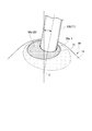
- FIG. 1 is a view of a chair 1 according to the embodiment as seen from the front
- FIG. 2 is a view showing a longitudinal section of the chair 1 as a whole.
- the chair 1 has an installation base 10 placed on an installation surface such as a floor of a building, and stands up from the installation base 10 in a circumferential direction centered on the standing position.
- a cylindrical leg column 11 supported by the installation base 10 so as to be tiltable in an arbitrary direction, and a seat body 12 supported by the upper part of the leg column 11 and receiving the seating load of the seated person on the upper surface. ing.
- FIG. 3 is an enlarged view of the vertical section of the lower region of the chair 1 with the installation base 10 as the center.
- the installation base 10 includes a base frame 13 made of a sheet metal having a circular top view and a resin upper member 14 attached to the base frame 13 and covering the top of the base frame 13 with a circular top view.
- the upper member 14 bulges upward while drawing a gently curved surface from the outer peripheral edge portion toward the central portion, and the tilting portion in which the lower region of the pedestal 11 is tiltably inserted into the central region of the bulging portion.
- An allowable hole 15 is formed.
- the base frame 13 has a central region that protrudes upward, and this protruding portion is a flat wall that extends substantially horizontally.
- This flat wall is a support wall 16 that supports the lower surface of an elastic member 19 to be described later.
- a space 17 is provided between the upper surface of the support wall 16 of the base frame 13 and the upper member 14.
- the peripheral edge 15a of the tilt allowing hole 15 of the upper member 14 is formed by a thin wall having a substantially constant thickness, and the lower surface of the peripheral edge 15a is substantially in line with the shape of the upper surface of the peripheral edge 15a. , A substantially spherical arc surface.
- an annular installation member 90 that protrudes downward and contacts the installation surface is attached to the lower surface of the outer peripheral edge of the base frame 13.
- the installation member 90 is formed of a resin material that is difficult to slip, and is disposed on the inner side of the outer peripheral end portion of the installation base 10.
- a flat contact wall 18 made of a sheet metal having a circular plan view is integrally provided at the lower end portion of the pillar 11.
- the contact wall 18 is integrally attached to the lower end of the main body portion (inner cylinder 11A) of the pedestal 11 by welding or the like.
- a disc-like rubber-like elastic member 19 having a through hole 19 a in the center is interposed between the contact wall 18 and the support wall 16 in a state where the elastic member 19 is compressed by the contact wall 18 and the support wall 16 (a state in which the initial reaction force is accumulated).
- the lower end of the pillar 11 is supported by the installation base 10 via the elastic member 19 so as to be tiltable.
- the elastic member 19 urges the leg column 11 by an elastic reaction force so that the leg column 11 assumes a vertical posture which is an initial tilting posture.
- an insertion hole 20 having an inner diameter larger than that of the through hole 19 a of the elastic member 19 is formed in the center portion of the support wall 16 of the base frame 13.
- An annular sliding guide 21 made of a highly slidable resin member is attached to the peripheral edge of the lower surface of the insertion hole 20 of the support wall 16.
- a downwardly convex support surface 21 a having an arcuate cross section is formed on the inner peripheral edge of the sliding guide 21, a downwardly convex support surface 21 a having an arcuate cross section.
- the arcuate cross section of the support surface 21 a is formed continuously in the circumferential direction of the sliding guide 21.
- the slip-out restricting member 22 has a shaft portion 22a inserted into the through hole 19a of the elastic member 19, and a hemispherical head portion 22b continuously provided so as to project radially outward from the lower end of the shaft portion 22a. is doing.
- the head portion 22 b is a guide surface 23 whose upper outer surface is formed in a spherical shape, and this spherical portion is slidably abutting on the support surface 21 a of the sliding guide 21.
- the slip-out restricting member 22 is fixed to the contact wall 18 of the leg column 11 by a metal cylindrical spacer member 24 and a bolt 25 in a state where the guide surface 23 of the head portion 22b is in contact with the sliding guide 21.
- the spacer member 24 has a flange portion 24b at the upper end of the shaft portion 24a.
- a through hole 18a is formed in the abutting wall 18 of the pedestal 11, and a shaft portion 24a of the spacer member 24 is inserted into the through hole 18a from above.
- the flange portion 24 b of the spacer member 24 abuts on the upper surface of the abutting wall 18 and regulates the downward displacement of the spacer member 24.
- an internal thread to which the shaft portion of the bolt 25 is screwed is provided on the inner peripheral surface of the shaft portion 24 a of the spacer member 24.
- the shaft regulating member 22 is provided with a shaft hole 22c, and the shaft portion 24a of the spacer member 24 is inserted into the shaft hole 22c. Further, a recess 22b-1 communicating with the shaft hole 22c is formed on the end surface (the lower surface in FIG. 3) of the head portion 22b of the removal restricting member 22.
- the bolt 25 is screwed into the female thread of the spacer member 24 in the shaft hole 22c from the concave portion 22b-1 of the removal restricting member 22. When the bolt 25 is tightened into the spacer member 24, the tightening load of the bolt 25 is removed and acts on the support wall 16 of the installation base 10 via the head portion 22 b of the restriction member 22.
- the elastic member 19 interposed between the contact wall 18 and the support wall 16 is compressed.
- the drop-out restricting member 22 is pressed to a predetermined amount or more in the direction of the abutting wall 18 (the inner cylinder 11A of the pedestal 11), and the head of the bolt 25 is moved to the shaft portion 24a of the spacer member 24.
- the tightening of the bolt 25 (displacement in the proximity direction of the removal restricting member 22 with respect to the inner cylinder 11A) is restricted.
- the drop-out restricting member 22 when the drop-out restricting member 22 is fixed to the contact wall 18 by the bolt 25, the elastic member 19 is compressed by a predetermined amount by the contact wall 18 and the support wall 16. In this state, when the head portion 22 b of the drop-out restricting member 22 comes into contact with the slide guide 21, the drop of the pedestal 11 from the installation base 10 is restricted. In addition, the leg column 11 is allowed to tilt in any direction as the elastic member 19 sandwiched between the flat abutting wall 18 and the support wall 16 is bent, but when the leg column 11 tilts, The spherical guide surface 23 of the head portion 22 b of the slip-out restricting member 22 slides on the support surface 21 a of the sliding guide 21, whereby the tilting of the pedestal 11 is guided.
- the pedestal 11 tilts around the vicinity of the center C of the spherical guide surface 23 below the elastic member 19.
- the elastic member 19 is compressed by a predetermined amount by fixing the drop-out restricting member 22 to the abutting wall 18 by the spacer member 24 and the bolt 25.
- the member 22 may be compressed in advance before being fixed to the abutting wall 18.
- a metal support member 27 having a frustoconical shape is attached to the upper surface of the contact wall 18.
- a cover member 26 that closes the gap between the tilt allowable hole 15 and the pedestal 11 from below is disposed near the tilt allowable hole 15 of the upper member 14.
- the cover member 26 is integrally formed of resin, and a thin cover main body portion 26a is formed by a substantially spherical solid surface.
- a through-hole 26a-1 through which the inner cylinder 11A of the pedestal 11 is inserted is formed at the center of the cover body 26a. Further, a protrusion 26b that protrudes downward in a cylindrical shape is provided on the lower surface of the outer peripheral edge of the through hole 26a-1 of the cover body 26a.
- the support member 27 attached to the abutting wall 18 is formed in a truncated cone shape from a metal material.
- the support member 27 includes an outward flange 27a, a tapered cylindrical portion 27b extending from the inner end portion of the outward flange 27a and gradually decreasing in diameter upward, and an upper end of the cylindrical portion 27b.
- an upper wall portion 27c that is bent inward in the radial direction and extends substantially horizontally.
- a through hole 27c-1 is formed at the center of the upper wall portion 27c.
- the inner cylinder 11A of the pedestal 11 is fitted into the through hole 27c-1, and the peripheral edge of the through hole 27c-1 is fixed to the outer surface of the inner cylinder 11A by welding.
- the outward flange 27a is placed on the upper surface of the contact wall 18 and is fixed to the contact wall 18 by a fastening member 50 such as a bolt and a nut.
- An annular reinforcing plate 27d extending substantially horizontally is fixed to the inner peripheral surface of the cylindrical portion 27b by welding.
- the inner cylinder 11A of the pedestal 11 is fitted into the inner peripheral part of the reinforcing plate 27d, and the inner peripheral part of the reinforcing plate 27d is fixed to the outer peripheral surface of the inner cylinder 11A by welding.
- the outward flange 27a of the support member 27 constitutes a lower wall portion that contacts the upper surface of the contact wall 18, and the cylindrical portion 27b and the upper wall portion 27c are located upward from the lower wall portion.
- An upright wall portion that stands up and abuts on the pedestal 11 is configured.
- the pedestal 11 is disposed across the outer cylinder 11B having a seat support member 28 attached to the upper end, the inner cylinder 11A assembled to the outer cylinder 11B so as to freely advance and retract, and the seat support member 28 and the inner cylinder 11A.
- a gas spring 29 for adjusting the expansion / contraction length of the inner cylinder 11A and the outer cylinder 11B.
- the gas spring 29 has an expansion / contraction length between the inner cylinder 11 ⁇ / b> A and the outer cylinder 11 ⁇ / b> B (elevating height of the seat body 12) when a not-shown expansion / contraction adjustment section provided at the upper end is pressed by an operation lever 30 described later. Can be adjusted freely.
- FIG. 4 is an enlarged view of a vertical section of the upper region of the chair 1 with the seat body 12 as the center
- FIG. 5 is an exploded view of a part of the seat body 12.
- the seat support member 28 includes a main body block 28A to which the seat body 12 is attached to the upper end surface, and a boss portion 28B that is integrally provided at the lower end of the main body block 28A and is fitted and fixed to the upper end portion of the outer cylinder 11B. It is equipped with.
- the upper end portion of the gas spring 29 is fitted and fixed to the axial center portion of the boss portion 28B and the main body block 28A.
- a concave portion 28A-1 in which the push operation portion 30a at the base end of the operation lever 30 is disposed is formed at substantially the center of the upper surface of the main body block 28A.
- the operating lever 30 is connected to an annular ring operating portion 30b, a plurality of connecting arm portions 30c extending radially inward from the ring operating portion 30b, and radially inner ends of the plurality of connecting arm portions 30c.
- a boss portion 30d, and the push operation portion 30a is held by the boss portion 30d.
- the ring operation portion 30b of the operation lever 30 is coaxially disposed on the radially outer side of the main body block 28A of the seat support member 28.
- the body block 28A of the seat support member 28 is formed with a plurality of insertion grooves 28A-2 through which the connecting arm portions 30c of the operation lever 30 are inserted.
- a metal closing plate 31 is attached to the upper surface of the main body block 28A. The upper displacement of the boss portion 30 d of the operation lever 30 and each connecting arm portion 30 c is regulated by the closing plate 31.
- the seat 12 includes a hard resin seat plate 32 fixed to the upper surface of the main body block 28 ⁇ / b> A of the seat support member 28, a cushion material 33 that is an interior material supported on the upper surface of the seat plate 32, and the cushion material 33. Covers the outer surface of the upper surface and the outer peripheral edge, and is attached to the lower surface of the outer peripheral edge of the seat plate 32 and the skin material 34 fixed to the seat plate 32 by being squeezed inward by the outer peripheral edge on the lower surface side of the seat plate 32. And a resin-made seat plate cover 35 covering the lower surface and the outer peripheral edge of the seat plate 32.
- symbol 40 in FIG. 4 is a string material for contracting the outer-periphery edge part of the skin material 34 which covered the cushion material 33 on the lower surface side of the seat board 32.
- a seated person can sit on the seat body 12 as follows.
- the seated person stands rearward in front of the seat body 12 of the chair 1, puts his hand on the seat body 12, and sits down on the upper surface of the seat body 12.
- the pedestal 11 of the chair 1 is appropriately tilted with respect to the installation base 10 according to the position and direction of the load applied from the seated person to the seat body 12.
- the elastic member 19 interposed between the installation base 10 and the leg column 11 is deformed, and a reaction force corresponding to the tilt of the leg column 11 is generated in the elastic member 19.
- the chair 1 stops the tilting of the pedestal 11 when the reaction force accumulated in the elastic member 19 and the load inputted to the seat body 12 through the buttocks of the seated person are balanced. In this state, the seated person's buttocks are stably held on the upper surface of the seat body 12.
- FIG. 6 is a diagram illustrating the behavior when the pedestal 11 is tilted with respect to the installation base 10.
- the elastic member 19 interposed between the abutment wall 18 and the support wall 16 is on the side where the load is applied.
- the spherical guide surface 23 of the drop-out restricting member 22 positioned below the elastic member 19 slides with respect to the support surface 21a of the slide guide 21, and this sliding causes the leg 11 Is tilted.
- the leg column 11 when the leg column 11 is tilted, the leg column 11 tilts about the vicinity of the center C of the spherical guide surface 23, so that the upper portion of the elastic member 19 sandwiched between the abutment wall 18 and the support wall 16.
- the moment of the force toward the vicinity of the center C of the spherical guide surface 23 acts from the entire lower surface of the contact wall 18 in contact with the elastic member 19. Therefore, loads in the compression direction and the shear direction are accumulated as elastic reaction forces in a wide area of the elastic member 19. As a result, a local load is unlikely to act on the elastic member 19.
- the drop-out restricting member 22 provided at the lower end of the pedestal 11 includes the spherical guide surface 23 convex upward, and the drop-out restricting member 22 is restricted when the pedestal 11 is tilted.
- the elastic member 19 is elastically deformed while the guide surface 23 of the member 22 is in sliding contact with the sliding guide 21 of the installation base 10. For this reason, when the leg column 11 is tilted, it is possible to suppress a local load from acting on the elastic member 19 and to obtain a smooth tilt of the leg column 11 and a stable elastic reaction force by the elastic member 19. .
- the guide surface 23 of the drop-out restricting member 22 is formed in an upward convex spherical shape, and the pedestal 11 is located near the center C of the guide surface 23 below the elastic member 19. Tilt as the center. Therefore, when the pedestal 11 is tilted, a load is input from the entire lower surface of the contact wall 18 in contact with the elastic member 19 as a moment of force toward the vicinity of the center C of the guide surface 23 on the upper portion of the elastic member 19. Elastic reaction force can be accumulated in a wide area of the elastic member 19. Therefore, in the chair 1 according to this embodiment, the durability of the elastic member 19 is advantageous, and a sufficient tilting reaction force can be obtained without causing an increase in the thickness of the elastic member 19.
- the elastic member 19 is sandwiched and fixed in a compressed state between the abutting wall 18 of the pedestal 11 and the support wall 16 of the installation base 10, so that the elastic member when seated The large depression of the pedestal 11 accompanying the deformation of 19 and the rapid tilting of the pedestal 11 can be suppressed.
- the support surface 21a of the sliding guide 21 that guides the guide surface 23 of the drop-out restricting member 22 is formed by a convex curved surface, the tilting position of the pedestal 11 is set. Regardless, the spherical guide surface 23 of the removal restricting member 22 can be supported in a line contact state by the support surface 21 a of the sliding guide 21. Therefore, by adopting this structure, unnecessary sliding resistance in the sliding guide 21 can be reduced, and stable tilting of the pedestal 11 can be obtained.
- the support surface 21a of the sliding guide 21 is formed in an annular shape along the peripheral area of the insertion hole 20 of the support wall 16, the pedestal 11 is tilted in any direction.
- the spherical guide surface 23 can be supported by the sliding guide 21 in a line contact state.
- the support wall 16 and the slide guide 21 of the installation base 10 are configured as separate parts, the support wall 16 is formed of a solid metal material, and the slide guide 21 is It is made of a highly slidable resin. For this reason, it is possible to easily improve the slidability with respect to the guide surface 23 of the drop-out restricting member 22 while ensuring sufficient rigidity and strength of the support wall 16.
- a contact wall 18 is provided at the lower end of the main body portion (inner cylinder 11A) of the pedestal 11 so as to protrude outward in the radial direction from the main body portion of the pedestal 11. Yes. Therefore, the load accompanying the tilting of the pedestal 11 can be applied to the upper surface of the elastic member 19 over a wide area of the contact wall 18. Therefore, the load accompanying the tilting of the pedestal 11 can be distributed over a wider area of the elastic member 19, and the local load acting on the elastic member 19 can be further reduced.
- the drop-out restricting member 22 is configured as a separate part from the member (contact wall 18) of the main body of the pedestal 11, and is elastic between the contact wall 18 and the support wall 16.
- the drop-out restricting member 22 is fastened together and fixed, and a spacer member 24 is provided that restricts the displacement of the drop-out restricting member 22 with respect to the contact wall 18 and the displacement in the separation direction. .
- the guide surface 23 is guided by the sliding guide 21 and the pedestal 11 is tilted. The tilt of the pedestal 11 can be stabilized.
- the behavior of the cover member 26 when the pedestal 11 is tilted with respect to the installation base 10 will be mainly discussed.
- the elastic member 19 interposed between the abutment wall 18 and the support wall 16 is on the side where the load is applied.
- the spherical guide surface 23 of the drop-out restricting member 22 positioned below the elastic member 19 slides with respect to the sliding guide 21, and the sliding of the leg column 11 guides the sliding. Is done. Accordingly, the pedestal 11 is tilted in the direction in which the load is applied around the vicinity of the center C of the spherical guide surface 23 at this time.
- the outer peripheral edge portion of the cover main body portion 26a of the cover member 26 is the lower surface of the peripheral edge portion 15a of the tilt allowable hole 15 as shown in FIG. Near or slidably touches.
- the cover member 26 is supported by the support member 27 at the protrusion 26b on the lower surface.
- the downward displacement is only restricted. Therefore, the contact impact received from the installation base 10 by the protrusion 26b sliding on the support member 27 or slightly rising is performed.
- the chair 1 has a cover that closes the gap between the tilting permissible hole 15 and the pedestal 11 above the contact wall 18 that is in contact with the elastic member 19 at the lower end of the pedestal 11.
- a member 26 is disposed.
- the cover member 26 is engaged with the pedestal 11 so as to be integrally tiltable, and downward displacement is restricted to the contact wall 18 in a non-fixed state.
- the clearance gap between the tilt permission hole 15 and the leg pillar 11 can be obstruct
- FIG. it is possible to prevent excessive stress from acting on the cover member 26 when the pedestal 11 is tilted. Therefore, in the case of this chair 1, the expected performance of the cover member 26 can be stably maintained over a long period of time.
- the downward displacement of the cover member 26 is regulated by the abutting wall 18 that abuts on the elastic member 19.
- a displacement regulating portion such as a support flange is separately provided on the pedestal 11, and this displacement regulating is provided.
- the downward displacement of the cover member 26 may be regulated by the portion.
- the structure of the footnote 11 can be simplified to reduce the manufacturing cost.
- the cover main body portion 26a of the cover member 26 is formed in a substantially spherical shape centered around the tilt center of the pedestal 11. Therefore, even when the pedestal 11 is tilted in any direction, the distance and the contact pressure between the peripheral edge portion 15a of the tilt allowing hole 15 and the outer surface of the cover main body portion 26a can be more easily maintained.
- the abutting wall 18 that abuts the elastic member 19 is formed so as to protrude outward in the radial direction from the inner cylinder 11 ⁇ / b> A of the pedestal column 11. It is possible to act on a large area on the elastic member 19. Therefore, by adopting this structure, the reaction force by the elastic member 19 can be increased efficiently.
- a support member 27 that is in contact with the cover member 26 from below is installed on the upper portion of the contact wall 18. Therefore, the cover member 26 can be stably supported from below by the support member 27 standing upward while keeping the contact wall 18 in a flat shape that can easily transmit the load to the elastic member 19. Therefore, by adopting this structure, it is possible to achieve both stable load transmission from the contact wall 18 to the elastic member 19 and prevention of the downward displacement of the cover member 26.
- an outward flange 27a that is a lower wall portion that comes into contact with the upper surface of the contact wall 18, a cylindrical portion 27b that is a standing wall portion that stands upward from the outward flange 27a, and an upper wall It has a portion 27c.
- the cover member 26 is moved in a state where the outward flange 27a as the lower wall portion is brought into contact with the contact wall 18 and the cylindrical portion 27b and the upper wall portion 27c as the standing wall portions are brought into contact with the leg pillars.
- the support member 27 can be stably supported in a non-contact state from below.
- the upright wall portion of the support member 27 includes a cylindrical portion 27b extending upward from the outward flange 27a, and an upper portion of the cylindrical portion 27b is bent to extend substantially horizontally so that the inner peripheral edge portion is And an upper wall portion 27c that comes into contact with the inner cylinder 11A.
- the support member 27 has a crank-like cross-sectional shape with high rigidity, and can efficiently receive the load in the falling direction of the support member 27. Therefore, by adopting this structure, the shape of the support member 27 can be stably maintained, and the cover member 26 can always be stably supported from below.
- the protrusion 26b that slidably contacts the support member 27 is provided on the lower surface of the cover member 26, the height of the support member 27 is prevented from becoming higher than necessary.
- the lower surface side of the cover member 26 can be stably supported by the support member 27 by the protrusion 26b.
- the installation base 10 is movably mounted on an installation surface such as a floor of a building.
- the installation base 10 can be fixedly installed on the installation surface. .
- the reaction force can be accumulated over a wide range of the elastic member when the pedestal is tilted, and the load acting locally on the elastic member can be reduced.
- a smooth tilt reaction of the pedestal and a stable elastic reaction force by the elastic member can be obtained.
- the cover member since the cover member is not fixed to the pedestal and the downward displacement is restricted, and the excessive stress is unlikely to act on the cover member, the intended performance of the cover member should be maintained stably over a long period of time. Can do.
Landscapes
- Chairs Characterized By Structure (AREA)
- Chair Legs, Seat Parts, And Backrests (AREA)
Priority Applications (3)
| Application Number | Priority Date | Filing Date | Title |
|---|---|---|---|
| EP16862204.1A EP3372118B1 (en) | 2015-11-06 | 2016-11-04 | Chair |
| US15/772,725 US10362876B2 (en) | 2015-11-06 | 2016-11-04 | Chair |
| CN201680063561.3A CN108289546B (zh) | 2015-11-06 | 2016-11-04 | 椅子 |
Applications Claiming Priority (4)
| Application Number | Priority Date | Filing Date | Title |
|---|---|---|---|
| JP2015218888A JP6566561B2 (ja) | 2015-11-06 | 2015-11-06 | 椅子 |
| JP2015-218924 | 2015-11-06 | ||
| JP2015218924A JP6566562B2 (ja) | 2015-11-06 | 2015-11-06 | 椅子 |
| JP2015-218888 | 2015-11-06 |
Publications (1)
| Publication Number | Publication Date |
|---|---|
| WO2017078145A1 true WO2017078145A1 (ja) | 2017-05-11 |
Family
ID=58662279
Family Applications (1)
| Application Number | Title | Priority Date | Filing Date |
|---|---|---|---|
| PCT/JP2016/082826 WO2017078145A1 (ja) | 2015-11-06 | 2016-11-04 | 椅子 |
Country Status (4)
| Country | Link |
|---|---|
| US (1) | US10362876B2 (zh) |
| EP (1) | EP3372118B1 (zh) |
| CN (1) | CN108289546B (zh) |
| WO (1) | WO2017078145A1 (zh) |
Cited By (4)
| Publication number | Priority date | Publication date | Assignee | Title |
|---|---|---|---|---|
| CN107568974A (zh) * | 2017-09-28 | 2018-01-12 | 重庆军工产业集团有限公司 | 应急指挥车用防滑椅子 |
| JP2020065872A (ja) * | 2018-10-26 | 2020-04-30 | 有限会社ルネセイコウ | 椅子 |
| US11006754B2 (en) * | 2018-04-12 | 2021-05-18 | American Leather Operations, Llc | Motion chair |
| US20220240681A1 (en) * | 2019-06-10 | 2022-08-04 | Inventor Group Gmbh | Tiltable Stool |
Families Citing this family (10)
| Publication number | Priority date | Publication date | Assignee | Title |
|---|---|---|---|---|
| US10905244B2 (en) * | 2016-05-24 | 2021-02-02 | Maria Terese ENGELL | Balance chair |
| USD910324S1 (en) * | 2018-06-13 | 2021-02-16 | Shou-Ping Tao | Wobble chair |
| CN111214029A (zh) * | 2018-11-23 | 2020-06-02 | 恒林家居股份有限公司 | 一种具有摇摆功能的坐具 |
| HUP1800441A1 (hu) * | 2018-12-21 | 2020-06-29 | Ferenc Benesch | Aktív szék, elsõsorban irodai használatra |
| IT201900003255A1 (it) * | 2019-03-06 | 2020-09-06 | Donati Spa | Base di appoggio per una seduta oscillante |
| US10966528B1 (en) * | 2019-08-08 | 2021-04-06 | Ronald B. Johnson | Spring stool |
| KR102193566B1 (ko) * | 2019-09-19 | 2020-12-21 | 체어마이스터 주식회사 | 경동 의자 |
| USD1005093S1 (en) * | 2019-11-09 | 2023-11-21 | Society Brands, Inc. | Chair locking mechanism |
| DE102020103861B3 (de) * | 2020-02-14 | 2021-04-29 | Hellstern medical GmbH | Operationsstuhl |
| KR102275811B1 (ko) * | 2020-10-23 | 2021-07-09 | 체어마이스터 주식회사 | 경동 의자 |
Citations (4)
| Publication number | Priority date | Publication date | Assignee | Title |
|---|---|---|---|---|
| FR1170615A (fr) * | 1957-04-04 | 1959-01-16 | Tabouret d'opérateur plus spécialement pour dentistes | |
| DE2642112A1 (de) * | 1975-10-02 | 1978-03-23 | Alfred Von Schuckmann | Sitz |
| DE202008017086U1 (de) * | 2008-12-24 | 2009-03-05 | Fritz Becker Kg | Bewegungsstuhl |
| DE102010036129A1 (de) * | 2010-09-01 | 2012-03-01 | Girsberger Holding Ag | Stehhilfe |
Family Cites Families (18)
| Publication number | Priority date | Publication date | Assignee | Title |
|---|---|---|---|---|
| DE1829791U (de) * | 1961-02-08 | 1961-04-20 | Franz Michael Laux | Pendelschemel- oder pendelstuhl. |
| US6098937A (en) * | 1998-01-08 | 2000-08-08 | Carnahan; Garnett | Support stand, assembly using the same, and method of making the same |
| AU3141400A (en) * | 1999-03-18 | 2000-10-09 | Thomas Walser | Seating device with an elastic support element and seat element for a seating device |
| CN2587249Y (zh) * | 2002-12-06 | 2003-11-26 | 易川 | 逍遥旋转椅 |
| NO328660B1 (no) * | 2008-04-02 | 2010-04-19 | Sapdesign As | Anordning ved stol |
| CN201270990Y (zh) * | 2008-05-28 | 2009-07-15 | 东莞市美缇皮具有限公司 | 座椅的返回装置 |
| US8646841B2 (en) * | 2009-08-13 | 2014-02-11 | Mary Ann Molnar | Seat with a non-vertical central supporting column and tri-planar moveable base |
| US8540314B2 (en) | 2009-10-28 | 2013-09-24 | Products Of Tomorrow, Inc. | Flex chair |
| CN102232737A (zh) * | 2010-05-07 | 2011-11-09 | 上海市格致中学 | 防摔摇椅 |
| WO2013008868A1 (ja) * | 2011-07-12 | 2013-01-17 | 株式会社岡村製作所 | カート装置 |
| CN202739347U (zh) * | 2012-06-27 | 2013-02-20 | 安吉艺维斯家具有限公司 | 一种可摇摆的酒吧椅 |
| EP2721965B1 (de) * | 2012-10-19 | 2015-05-06 | aeris GmbH | Sitzmöbel mit Verdrehsicherung |
| US20140332644A1 (en) * | 2013-03-19 | 2014-11-13 | Gerald Ray Davis | Handy Drink Holder |
| CN204091452U (zh) * | 2014-09-22 | 2015-01-14 | 安吉县聚源家具有限公司 | 一种能使转动轴心对齐的吧椅 |
| CN205795340U (zh) * | 2016-05-19 | 2016-12-14 | 强龙家具股份有限公司 | 一种能够倾仰摆动的椅子 |
| CN205795341U (zh) * | 2016-05-19 | 2016-12-14 | 强龙家具股份有限公司 | 一种双向控制气杆阀门的椅子 |
| US9763520B1 (en) * | 2016-08-15 | 2017-09-19 | Oasychair Co., Ltd | Reclinable office chair |
| US10034547B1 (en) * | 2017-03-03 | 2018-07-31 | Oasyschair Co., Ltd. | Reclinable office chair |
-
2016
- 2016-11-04 WO PCT/JP2016/082826 patent/WO2017078145A1/ja active Application Filing
- 2016-11-04 US US15/772,725 patent/US10362876B2/en active Active
- 2016-11-04 CN CN201680063561.3A patent/CN108289546B/zh active Active
- 2016-11-04 EP EP16862204.1A patent/EP3372118B1/en active Active
Patent Citations (4)
| Publication number | Priority date | Publication date | Assignee | Title |
|---|---|---|---|---|
| FR1170615A (fr) * | 1957-04-04 | 1959-01-16 | Tabouret d'opérateur plus spécialement pour dentistes | |
| DE2642112A1 (de) * | 1975-10-02 | 1978-03-23 | Alfred Von Schuckmann | Sitz |
| DE202008017086U1 (de) * | 2008-12-24 | 2009-03-05 | Fritz Becker Kg | Bewegungsstuhl |
| DE102010036129A1 (de) * | 2010-09-01 | 2012-03-01 | Girsberger Holding Ag | Stehhilfe |
Cited By (7)
| Publication number | Priority date | Publication date | Assignee | Title |
|---|---|---|---|---|
| CN107568974A (zh) * | 2017-09-28 | 2018-01-12 | 重庆军工产业集团有限公司 | 应急指挥车用防滑椅子 |
| US11006754B2 (en) * | 2018-04-12 | 2021-05-18 | American Leather Operations, Llc | Motion chair |
| US11583085B2 (en) | 2018-04-12 | 2023-02-21 | American Leather Operations, Llc | Motion chair |
| US11910932B2 (en) | 2018-04-12 | 2024-02-27 | American Leather Operations, Llc | Motion chair |
| JP2020065872A (ja) * | 2018-10-26 | 2020-04-30 | 有限会社ルネセイコウ | 椅子 |
| JP7078263B2 (ja) | 2018-10-26 | 2022-05-31 | 有限会社ルネセイコウ | 椅子 |
| US20220240681A1 (en) * | 2019-06-10 | 2022-08-04 | Inventor Group Gmbh | Tiltable Stool |
Also Published As
| Publication number | Publication date |
|---|---|
| EP3372118A4 (en) | 2019-05-01 |
| CN108289546A (zh) | 2018-07-17 |
| EP3372118A1 (en) | 2018-09-12 |
| US10362876B2 (en) | 2019-07-30 |
| EP3372118B1 (en) | 2020-01-01 |
| US20190200769A1 (en) | 2019-07-04 |
| CN108289546B (zh) | 2021-01-12 |
Similar Documents
| Publication | Publication Date | Title |
|---|---|---|
| WO2017078145A1 (ja) | 椅子 | |
| US9016786B2 (en) | Moveable item of seating furniture comprising a device for controlling the return force | |
| JP7130094B2 (ja) | 椅子 | |
| JP7514276B2 (ja) | ランバーサポート装置付き椅子 | |
| US10765214B2 (en) | Guide spring for a seating device and sprung seating device | |
| AU2017329476B2 (en) | Seating furniture | |
| JP6566561B2 (ja) | 椅子 | |
| JP6989604B2 (ja) | 椅子 | |
| JP6566562B2 (ja) | 椅子 | |
| JP6739161B2 (ja) | 椅子 | |
| JP7055135B2 (ja) | 椅子 | |
| JP6339841B2 (ja) | 椅子 | |
| JP2007007249A (ja) | 椅子 | |
| JP6662609B2 (ja) | 椅子 | |
| JP4353472B2 (ja) | 椅子 | |
| JP4512916B2 (ja) | 椅子の座 | |
| JP6141754B2 (ja) | 椅子のロッキング機構および椅子 | |
| JP6650763B2 (ja) | 什器 | |
| KR102058116B1 (ko) | 경동 의자 | |
| JP6927730B2 (ja) | 椅子用荷重支持部材 | |
| JP3525239B2 (ja) | 椅子の背凭れスライド装置 | |
| JP2018064905A (ja) | 椅子用背凭れ、及び、椅子 | |
| KR20230065795A (ko) | 의자용 마운트 | |
| JP2021036951A (ja) | 椅子 | |
| JP2017124105A (ja) | 什器 |
Legal Events
| Date | Code | Title | Description |
|---|---|---|---|
| 121 | Ep: the epo has been informed by wipo that ep was designated in this application |
Ref document number: 16862204 Country of ref document: EP Kind code of ref document: A1 |
|
| NENP | Non-entry into the national phase |
Ref country code: DE |
|
| WWE | Wipo information: entry into national phase |
Ref document number: 2016862204 Country of ref document: EP |