WO2017064957A1 - 内燃機関用のスパークプラグ - Google Patents
内燃機関用のスパークプラグ Download PDFInfo
- Publication number
- WO2017064957A1 WO2017064957A1 PCT/JP2016/076608 JP2016076608W WO2017064957A1 WO 2017064957 A1 WO2017064957 A1 WO 2017064957A1 JP 2016076608 W JP2016076608 W JP 2016076608W WO 2017064957 A1 WO2017064957 A1 WO 2017064957A1
- Authority
- WO
- WIPO (PCT)
- Prior art keywords
- gap
- insulator
- filler
- base end
- spark plug
- Prior art date
- Legal status (The legal status is an assumption and is not a legal conclusion. Google has not performed a legal analysis and makes no representation as to the accuracy of the status listed.)
- Ceased
Links
Images

Classifications
-
- H—ELECTRICITY
- H01—ELECTRIC ELEMENTS
- H01T—SPARK GAPS; OVERVOLTAGE ARRESTERS USING SPARK GAPS; SPARKING PLUGS; CORONA DEVICES; GENERATING IONS TO BE INTRODUCED INTO NON-ENCLOSED GASES
- H01T13/00—Sparking plugs
- H01T13/20—Sparking plugs characterised by features of the electrodes or insulation
- H01T13/36—Sparking plugs characterised by features of the electrodes or insulation characterised by the joint between insulation and body, e.g. using cement
-
- H—ELECTRICITY
- H01—ELECTRIC ELEMENTS
- H01T—SPARK GAPS; OVERVOLTAGE ARRESTERS USING SPARK GAPS; SPARKING PLUGS; CORONA DEVICES; GENERATING IONS TO BE INTRODUCED INTO NON-ENCLOSED GASES
- H01T13/00—Sparking plugs
- H01T13/20—Sparking plugs characterised by features of the electrodes or insulation
- H01T13/34—Sparking plugs characterised by features of the electrodes or insulation characterised by the mounting of electrodes in insulation, e.g. by embedding
-
- H—ELECTRICITY
- H01—ELECTRIC ELEMENTS
- H01T—SPARK GAPS; OVERVOLTAGE ARRESTERS USING SPARK GAPS; SPARKING PLUGS; CORONA DEVICES; GENERATING IONS TO BE INTRODUCED INTO NON-ENCLOSED GASES
- H01T13/00—Sparking plugs
- H01T13/20—Sparking plugs characterised by features of the electrodes or insulation
- H01T13/38—Selection of materials for insulation
Definitions
- This disclosure relates to a spark plug for an internal combustion engine.
- spark plugs are used as ignition devices for internal combustion engines.
- spark plugs In an environment where the discharge voltage is high, spark plugs cause creeping insulation breakdown, so-called flashover, between the base end of the insulator and the terminal fitting on the plug head, or between the base end of the housing and the insulator. It becomes easy to do. When flashover occurs, spark discharge does not occur at the plug tip, and ignition of fuel gas is hindered.
- Patent Document 1 discloses that the terminal metal fitting of the plug head is inclined by inclining the contact surface of the terminal metal fitting in accordance with the inclination of the base end portion of the insulator. A configuration with reduced eccentricity and bending is disclosed. This increases the creepage distance through the surface of the insulator between the center electrode and the terminal fitting, making it difficult for the creeping streamer to reach the negative corona discharge and suppressing the occurrence of flashover. Yes.
- This disclosure intends to provide a spark plug for an internal combustion engine in which occurrence of flashover is suppressed and damage to an insulator is prevented.
- a spark plug for an internal combustion engine includes a cylindrical housing; A cylindrical insulator held inside the housing such that the base end protrudes; A center electrode held inside the insulator so that the tip protrudes; and A terminal fitting connected to the proximal end of the insulator and provided to energize the center electrode; A grounding electrode fixed to the tip of the housing and forming a spark discharge gap with the tip of the center electrode; and Fill at least one of the first gap formed between the base end of the insulator and the terminal fitting and the second gap formed between the base end of the housing and the insulator. The agent is filled.
- At least one of the first gap and the second gap is filled with the filler, and an air layer is prevented from being formed in the gap.
- the ionization of the air layer due to the concentration of the electric field in the gap when a high voltage is applied to the center electrode is suppressed, and the occurrence of corona discharge is suppressed. Therefore, the occurrence of flashover due to the occurrence of the corona discharge is also suppressed.
- this structure since it is not necessary to incline the contact surface of a terminal metal fitting according to the inclination of the base end part of an insulator, an insulator is damaged at the time of fusion
- FIG. 1 is a partial front sectional view of a spark plug in Embodiment 1.
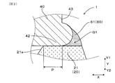
- FIG. 2 is a partially enlarged view of a cross section in the vicinity of the first gap of the spark plug in Embodiment 1.
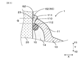
- FIG. 3 is a partially enlarged cross-sectional view of the vicinity of the second gap of the spark plug in Embodiment 1.
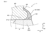
- FIG. 4 is a partially enlarged view of a cross section near the first gap of the spark plug in Modification 1.
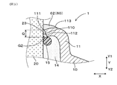
- FIG. 5 is a partially enlarged cross-sectional view in the vicinity of the second gap of the spark plug in Modification 2.
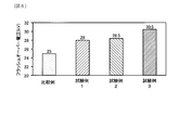
- FIG. 6 is a diagram showing measurement results of flashover voltage in Test Examples 1 to 3 and Comparative Example.
- a spark plug 1 for an internal combustion engine includes a housing 10, an insulator 20, a center electrode 30, a terminal fitting 40 and a ground electrode 50.
- the housing 10 has a cylindrical shape.
- the insulator 20 has a cylindrical shape, and is held inside the housing 10 so that the base end portion 21 of the insulator 20 protrudes.
- the center electrode 30 is held inside the insulator 20 so that the tip 32 of the center electrode 30 protrudes.
- the terminal fitting 40 is connected to the base end portion 21 of the insulator 20 and is provided to energize the center electrode 30.
- the ground electrode 50 is fixed to the distal end portion 12 of the housing 10 and forms a spark discharge gap G0 between the ground electrode 50 and the distal end portion 32 of the center electrode 30.
- the first gap G1 formed between the base end 21 of the insulator 20 and the terminal fitting 40 and the second gap G2 formed between the base end 11 of the housing 10 and the insulator 20 are provided. At least one is filled with a filler 60.
- spark plug 1 for the internal combustion engine of the present embodiment
- the spark plug 1 for an internal combustion engine is also referred to as “spark plug 1”.
- the spark plug 1 can be used as ignition means in an internal combustion engine provided in an automobile or the like.
- a side inserted into a combustion chamber (not shown) is a front end side, and an end portion on the front end side is a front end portion.
- the side opposite to the distal end side is referred to as a proximal end side
- the end portion on the proximal end side is referred to as a proximal end portion.
- the plug axial direction Y means the axial direction of the spark plug 1.
- a direction from the distal end portion toward the proximal end portion is defined as a proximal end direction Y1
- a direction from the proximal end portion toward the distal end portion is defined as a distal end direction Y2.
- the housing 10 is made of metal and has a cylindrical shape extending in the plug axis direction Y.
- a mounting screw portion 13 is formed on the outer peripheral surface of the housing 10 to be screwed into an internal combustion engine (not shown).
- the spark plug 1 is attached to the internal combustion engine via the attachment screw portion 13.
- An insulator 20 is inserted and held inside the housing 10.
- the insulator 20 has a cylindrical shape extending in the plug axis direction Y.
- a base end portion 21 of the insulator 20 protrudes from the base end portion 11 of the housing 10.
- An inclined surface 21 a is formed inside the base end portion 21 of the insulator 20.
- the insulator 20 is held in the housing 10 by caulking the base end portion 11 of the housing 10 via the talc 14 and the O-ring 15 at approximately the center in the plug axial direction Y. Yes.
- a center electrode 30 is inserted and held inside the insulator 20.
- the center electrode 30 has a rod shape extending in the plug axis direction Y.
- a center electrode side metal tip 33 is attached to the tip 32 of the center electrode 30 and protrudes from the tip 22 of the insulator 20.
- a terminal fitting 40 is provided at the base end portion 21 of the insulator 20.
- the terminal fitting 40 is configured to be electrically connected to the proximal end portion 31 of the center electrode 30 inserted and held inside the insulator 20 and to be energized with the center electrode 30.
- the terminal fitting 40 is fused and fixed to the proximal end portion 21 of the insulator 20.
- a base end portion 41 of the terminal fitting 40 is electrically connected to a secondary side of an ignition coil of an ignition device (not shown).
- the ground electrode 50 extends from the front end portion 12 of the housing 10 in the plug axis direction Y and is bent so as to intersect the axis 30 a of the center electrode 30.
- the ground electrode 50 is provided with a ground electrode side metal tip 53 at a position facing the center electrode side metal tip 33.
- the center electrode side metal tip 33 and the ground electrode side metal tip 53 are separated by a predetermined distance to form a spark discharge gap G0.
- the terminal fitting 40 has a facing portion 42 that faces the proximal end portion 21 of the insulator 20.
- the base end portion 21 of the insulator 20 and the facing portion 42 of the terminal fitting 40 are in contact with each other in the region P in the entire circumferential direction.
- a first gap G1 is formed between the base end portion 21 of the insulator 20 and the facing portion 42 of the terminal fitting 40.
- the first gap G1 is filled with the first filler 61. As shown in FIG. 1, the first filler 61 is filled all around the base end portion 21 of the insulator 20. In the present embodiment, the first filler 61 is provided to fill the entire first gap G1 and to slightly rise from the first gap G1 in order to reliably fill the first gap G1.
- the first filler 61 is not particularly limited as long as it is a material that can fill the first gap G1, but is preferably an insulating material such as silicon resin, fluororesin, or epoxy resin. In this embodiment, silicon resin is employed.
- a second gap G ⁇ b> 2 is formed between the base end portion 11 of the housing 10 and the insulator 20.
- the second gap G2 is located on the proximal side Y1 of the end surface 110 of the base end portion 11 in the plug axial direction Y in the region between the end surface 110 of the base end portion 11 of the housing 10 and the side surface 23 of the insulator 20.
- This is a space formed in a region Q from a base end side corner portion 111 that is an end portion to a front end side corner portion 112 that is an end portion of the front end side Y2.
- the second gap 62 is filled in the second gap G2.
- the second filler 62 is filled all around the base end portion 11 of the housing 10.
- the second filler 62 is provided not only in the second gap G2 but also in the proximal end Y1 of the second gap G2, as shown in FIG. Part 111 is covered.
- the spark plug 1 of the present embodiment includes the first filler 61 and the second filler 62 described above as the filler 60 as shown in FIG.
- the effect in the spark plug 1 of this embodiment is explained in full detail.
- the first gap G1 and the second gap G2 are filled with the first filler 61 and the second filler 62 as the filler 60, and the first gap G1 and the second gap G2 are filled with air. Formation of the layer is prevented.
- the ionization of the air layer due to the concentration of the electric field in the first gap G1 and the second gap G2 when a high voltage is applied to the center electrode 30 is suppressed, and the occurrence of corona discharge is suppressed. Therefore, the occurrence of flashover due to the occurrence of the corona discharge is also suppressed.
- the filler 60 is made of an insulating resin. Therefore, insulation is ensured in the first gap G1 and the second gap G2, and the occurrence of flashover is further suppressed.
- the filler 60 is filled in both the first gap G1 and the second gap G2. Thereby, the occurrence of flashover can be effectively prevented.
- the second filler 62 as the filler 60 may be filled in at least the second gap G2. In this case, since the occurrence of the creeping streamer is suppressed by suppressing the occurrence of positive corona discharge, the effect of preventing the occurrence of flashover can be ensured.
- the second filler 62 as the filler 60 covers the base end side corner 111 of the housing 10.
- the occurrence of positive corona discharge between the base end side corner portion 111 and the side surface 23 of the insulator 20 is suppressed, and the occurrence of creeping streamers is further suppressed, The occurrence of flashover is further prevented.
- the first filler 61 as the filler 60 may be filled in at least the first gap G1. In this case, by suppressing the occurrence of negative corona discharge in the first gap G1, the effect of suppressing the occurrence of flashover can be achieved.
- the first filler 61 filled in the first gap G ⁇ b> 1 may further cover a part of the tip end side surface 43 of the terminal fitting 40. Good. In this case, it is possible to further suppress the occurrence of negative corona discharge between the distal end side surface 43 of the terminal fitting 40 and the proximal end portion 21 of the insulator 20, and further suppress the occurrence of flashover. it can.
- the base end portion 11 of the housing 10 may be crimped so as to be wound around the distal end side Y2 which is the O ring 15 side.
- the second filler 62 as the filler 60 is positioned closer to the base end side Y1 than the base end side corner 111 in the plug axial direction Y in addition to the second gap G2.
- the base end portion 11 is provided so as to cover the base end side endmost portion 113.
- the present disclosure is not limited to the above-described embodiments and modifications, and can be applied to various embodiments without departing from the gist thereof.
- the formation mode of the second filler 62 in Embodiment 1 and the formation mode of the first filler 61 in Modification 1 are combined, or the formation mode of the first filler 61 in Embodiment 1 and the first aspect in Modification 1 are combined.
- the formation mode of the two fillers 62 may be combined.
- only one of the first filler 61 and the second filler 62 may be provided.
- Test Examples 1 to 3 which are spark plugs for an internal combustion engine of the present disclosure.
- the first gap G1 shown in FIG. 1 is filled with the first filler 61 as the filler 60, and the second gap G2 is not filled with the filler 60.
- the first gap G1 shown in FIG. 1 is not filled with the filler 60, and the second gap G2 is filled with the second filler 62 as the filler 60. It was.
- the spark plug of Test Example 3 has the same configuration as that of the above-described first embodiment, and as shown in FIG.
- each spark plug was immersed in insulating oil at the tip including the spark discharge gap G0 shown in FIG. 1 so that the base end was in the atmosphere so that no discharge occurred in the spark discharge gap G0. .
- a high voltage was applied at an applied frequency of 30 Hz from an ignition coil (not shown) connected to the terminal fitting 40.
- the applied voltage was gradually increased from 20 kV, and the flashover voltage, which was the applied voltage when flashover occurred between the first gap G1 and the second gap G2, was measured.
- the flashover voltage was 25 kV, but in test example 1, the flashover voltage was 28 kV, and in test example 2, the flashover voltage was 28.5 kV. Even the flashover voltage was rising. Further, in Test Example 3, the flashover voltage was 30.5 kV, the flashover voltage was higher than that of the comparative example, and the flashover voltage was higher than that of Test Examples 1 and 2.
Landscapes
- Spark Plugs (AREA)
Priority Applications (2)
| Application Number | Priority Date | Filing Date | Title |
|---|---|---|---|
| US15/768,106 US10790640B2 (en) | 2015-10-14 | 2016-09-09 | Spark plug for internal combustion engine |
| DE112016004687.1T DE112016004687B4 (de) | 2015-10-14 | 2016-09-09 | Zündkerze für eine Maschine mit interner Verbrennung |
Applications Claiming Priority (2)
| Application Number | Priority Date | Filing Date | Title |
|---|---|---|---|
| JP2015203199A JP6661958B2 (ja) | 2015-10-14 | 2015-10-14 | 内燃機関用のスパークプラグ |
| JP2015-203199 | 2015-10-14 |
Publications (1)
| Publication Number | Publication Date |
|---|---|
| WO2017064957A1 true WO2017064957A1 (ja) | 2017-04-20 |
Family
ID=58517557
Family Applications (1)
| Application Number | Title | Priority Date | Filing Date |
|---|---|---|---|
| PCT/JP2016/076608 Ceased WO2017064957A1 (ja) | 2015-10-14 | 2016-09-09 | 内燃機関用のスパークプラグ |
Country Status (4)
| Country | Link |
|---|---|
| US (1) | US10790640B2 (enExample) |
| JP (1) | JP6661958B2 (enExample) |
| DE (1) | DE112016004687B4 (enExample) |
| WO (1) | WO2017064957A1 (enExample) |
Citations (3)
| Publication number | Priority date | Publication date | Assignee | Title |
|---|---|---|---|---|
| JPH10125444A (ja) * | 1996-08-29 | 1998-05-15 | Denso Corp | イオン電流検出用スパークプラグおよびイオン電流検出装置 |
| JP2013016295A (ja) * | 2011-07-01 | 2013-01-24 | Ngk Spark Plug Co Ltd | スパークプラグ |
| JP2014167903A (ja) * | 2013-01-31 | 2014-09-11 | Ngk Spark Plug Co Ltd | 点火プラグ及びその製造方法 |
Family Cites Families (10)
| Publication number | Priority date | Publication date | Assignee | Title |
|---|---|---|---|---|
| JPS55164794U (enExample) | 1979-05-14 | 1980-11-26 | ||
| DE19737614B4 (de) | 1996-08-29 | 2010-04-08 | DENSO CORPORATION, Kariya-shi | Zündkerze für ein Gerät zur Erfassung eines Ionenstroms, ohne daß ein impulsartiges Rauschen auf dem Ionenstrom erzeugt wird |
| JPH11329666A (ja) | 1998-05-15 | 1999-11-30 | Ngk Spark Plug Co Ltd | スパークプラグ |
| JP2001135457A (ja) * | 1999-11-05 | 2001-05-18 | Denso Corp | スパークプラグ |
| JP2001203059A (ja) | 2000-01-17 | 2001-07-27 | Ngk Spark Plug Co Ltd | スパークプラグ用絶縁体並びにそれを備えるスパークプラグ及びその製造方法 |
| JP4596700B2 (ja) * | 2001-07-26 | 2010-12-08 | 日本特殊陶業株式会社 | スパークプラグ |
| KR20100017797A (ko) * | 2007-05-17 | 2010-02-16 | 페더럴-모굴 이그니션 컴퍼니 | 저항형 시일을 갖춘 작은 직경의 스파크 플러그 |
| WO2009122996A1 (ja) * | 2008-04-02 | 2009-10-08 | 日本特殊陶業株式会社 | スパークプラグ及びその製造方法 |
| JP5725486B1 (ja) | 2014-04-11 | 2015-05-27 | 一般社団法人 レトロフィットジャパン協会 | H型鋼柱の補強構造 |
| TWM556508U (zh) | 2017-12-07 | 2018-03-11 | 富粧生科股份有限公司 | 化妝品容器 |
-
2015
- 2015-10-14 JP JP2015203199A patent/JP6661958B2/ja active Active
-
2016
- 2016-09-09 US US15/768,106 patent/US10790640B2/en active Active
- 2016-09-09 WO PCT/JP2016/076608 patent/WO2017064957A1/ja not_active Ceased
- 2016-09-09 DE DE112016004687.1T patent/DE112016004687B4/de active Active
Patent Citations (3)
| Publication number | Priority date | Publication date | Assignee | Title |
|---|---|---|---|---|
| JPH10125444A (ja) * | 1996-08-29 | 1998-05-15 | Denso Corp | イオン電流検出用スパークプラグおよびイオン電流検出装置 |
| JP2013016295A (ja) * | 2011-07-01 | 2013-01-24 | Ngk Spark Plug Co Ltd | スパークプラグ |
| JP2014167903A (ja) * | 2013-01-31 | 2014-09-11 | Ngk Spark Plug Co Ltd | 点火プラグ及びその製造方法 |
Also Published As
| Publication number | Publication date |
|---|---|
| US20180309270A1 (en) | 2018-10-25 |
| US10790640B2 (en) | 2020-09-29 |
| JP6661958B2 (ja) | 2020-03-11 |
| JP2017076519A (ja) | 2017-04-20 |
| DE112016004687B4 (de) | 2023-08-10 |
| DE112016004687T5 (de) | 2018-07-05 |
Similar Documents
| Publication | Publication Date | Title |
|---|---|---|
| JP6095700B2 (ja) | コロナ先端絶縁体 | |
| US8499751B2 (en) | Internal combustion engine ignition coil device | |
| US11456578B2 (en) | Spark plug | |
| JP6238895B2 (ja) | 温度制御機能を有するコロナ点火器 | |
| JP6401246B2 (ja) | 気密性燃焼シールを備えるコロナ点火装置 | |
| JP5963908B1 (ja) | スパークプラグ | |
| WO2012147262A1 (ja) | スパークプラグ及びその製造方法 | |
| JP5888160B2 (ja) | 内燃機関用のスパークプラグ及びこれを備えた点火装置 | |
| WO2017064957A1 (ja) | 内燃機関用のスパークプラグ | |
| JPH10125444A (ja) | イオン電流検出用スパークプラグおよびイオン電流検出装置 | |
| JP2009193737A (ja) | 点火プラグ | |
| JP6557632B2 (ja) | スパークプラグ | |
| JP6476766B2 (ja) | 内燃機関用の点火コイル及びその取付構造 | |
| JP6686307B2 (ja) | 内燃機関用の点火コイル | |
| JP7070196B2 (ja) | 内燃機関用のスパークプラグ | |
| JP6592473B2 (ja) | 点火プラグ | |
| JP2017076519A5 (enExample) | ||
| JP2020004679A (ja) | 点火プラグ | |
| JP6903545B2 (ja) | 内燃機関用点火コイル | |
| JP6467370B2 (ja) | スパークプラグ | |
| JP6207573B2 (ja) | スパークプラグ用の絶縁体の検査方法 | |
| JP2017147020A (ja) | スパークプラグ | |
| JPWO2019069640A1 (ja) | 点火プラグ | |
| JPH04155792A (ja) | 高電圧スイッチ素子用ガス入り放電管及びこれを用いた点火プラグ | |
| JP2019009048A (ja) | 点火プラグ及び点火装置 |
Legal Events
| Date | Code | Title | Description |
|---|---|---|---|
| 121 | Ep: the epo has been informed by wipo that ep was designated in this application |
Ref document number: 16855211 Country of ref document: EP Kind code of ref document: A1 |
|
| WWE | Wipo information: entry into national phase |
Ref document number: 15768106 Country of ref document: US |
|
| WWE | Wipo information: entry into national phase |
Ref document number: 112016004687 Country of ref document: DE |
|
| 122 | Ep: pct application non-entry in european phase |
Ref document number: 16855211 Country of ref document: EP Kind code of ref document: A1 |