WO2017064957A1 - Spark plug for internal combustion engines - Google Patents
Spark plug for internal combustion engines Download PDFInfo
- Publication number
- WO2017064957A1 WO2017064957A1 PCT/JP2016/076608 JP2016076608W WO2017064957A1 WO 2017064957 A1 WO2017064957 A1 WO 2017064957A1 JP 2016076608 W JP2016076608 W JP 2016076608W WO 2017064957 A1 WO2017064957 A1 WO 2017064957A1
- Authority
- WO
- WIPO (PCT)
- Prior art keywords
- gap
- insulator
- filler
- base end
- spark plug
- Prior art date
Links
Images

Classifications
-
- H—ELECTRICITY
- H01—ELECTRIC ELEMENTS
- H01T—SPARK GAPS; OVERVOLTAGE ARRESTERS USING SPARK GAPS; SPARKING PLUGS; CORONA DEVICES; GENERATING IONS TO BE INTRODUCED INTO NON-ENCLOSED GASES
- H01T13/00—Sparking plugs
- H01T13/20—Sparking plugs characterised by features of the electrodes or insulation
- H01T13/36—Sparking plugs characterised by features of the electrodes or insulation characterised by the joint between insulation and body, e.g. using cement
-
- H—ELECTRICITY
- H01—ELECTRIC ELEMENTS
- H01T—SPARK GAPS; OVERVOLTAGE ARRESTERS USING SPARK GAPS; SPARKING PLUGS; CORONA DEVICES; GENERATING IONS TO BE INTRODUCED INTO NON-ENCLOSED GASES
- H01T13/00—Sparking plugs
- H01T13/20—Sparking plugs characterised by features of the electrodes or insulation
- H01T13/34—Sparking plugs characterised by features of the electrodes or insulation characterised by the mounting of electrodes in insulation, e.g. by embedding
-
- H—ELECTRICITY
- H01—ELECTRIC ELEMENTS
- H01T—SPARK GAPS; OVERVOLTAGE ARRESTERS USING SPARK GAPS; SPARKING PLUGS; CORONA DEVICES; GENERATING IONS TO BE INTRODUCED INTO NON-ENCLOSED GASES
- H01T13/00—Sparking plugs
- H01T13/20—Sparking plugs characterised by features of the electrodes or insulation
- H01T13/38—Selection of materials for insulation
Definitions
- This disclosure relates to a spark plug for an internal combustion engine.
- spark plugs are used as ignition devices for internal combustion engines.
- spark plugs In an environment where the discharge voltage is high, spark plugs cause creeping insulation breakdown, so-called flashover, between the base end of the insulator and the terminal fitting on the plug head, or between the base end of the housing and the insulator. It becomes easy to do. When flashover occurs, spark discharge does not occur at the plug tip, and ignition of fuel gas is hindered.
- Patent Document 1 discloses that the terminal metal fitting of the plug head is inclined by inclining the contact surface of the terminal metal fitting in accordance with the inclination of the base end portion of the insulator. A configuration with reduced eccentricity and bending is disclosed. This increases the creepage distance through the surface of the insulator between the center electrode and the terminal fitting, making it difficult for the creeping streamer to reach the negative corona discharge and suppressing the occurrence of flashover. Yes.
- This disclosure intends to provide a spark plug for an internal combustion engine in which occurrence of flashover is suppressed and damage to an insulator is prevented.
- a spark plug for an internal combustion engine includes a cylindrical housing; A cylindrical insulator held inside the housing such that the base end protrudes; A center electrode held inside the insulator so that the tip protrudes; and A terminal fitting connected to the proximal end of the insulator and provided to energize the center electrode; A grounding electrode fixed to the tip of the housing and forming a spark discharge gap with the tip of the center electrode; and Fill at least one of the first gap formed between the base end of the insulator and the terminal fitting and the second gap formed between the base end of the housing and the insulator. The agent is filled.
- At least one of the first gap and the second gap is filled with the filler, and an air layer is prevented from being formed in the gap.
- the ionization of the air layer due to the concentration of the electric field in the gap when a high voltage is applied to the center electrode is suppressed, and the occurrence of corona discharge is suppressed. Therefore, the occurrence of flashover due to the occurrence of the corona discharge is also suppressed.
- this structure since it is not necessary to incline the contact surface of a terminal metal fitting according to the inclination of the base end part of an insulator, an insulator is damaged at the time of fusion
- FIG. 1 is a partial front sectional view of a spark plug in Embodiment 1.
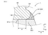
- FIG. 2 is a partially enlarged view of a cross section in the vicinity of the first gap of the spark plug in Embodiment 1.
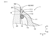
- FIG. 3 is a partially enlarged cross-sectional view of the vicinity of the second gap of the spark plug in Embodiment 1.
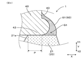
- FIG. 4 is a partially enlarged view of a cross section near the first gap of the spark plug in Modification 1.
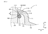
- FIG. 5 is a partially enlarged cross-sectional view in the vicinity of the second gap of the spark plug in Modification 2.
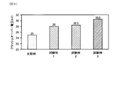
- FIG. 6 is a diagram showing measurement results of flashover voltage in Test Examples 1 to 3 and Comparative Example.
- a spark plug 1 for an internal combustion engine includes a housing 10, an insulator 20, a center electrode 30, a terminal fitting 40 and a ground electrode 50.
- the housing 10 has a cylindrical shape.
- the insulator 20 has a cylindrical shape, and is held inside the housing 10 so that the base end portion 21 of the insulator 20 protrudes.
- the center electrode 30 is held inside the insulator 20 so that the tip 32 of the center electrode 30 protrudes.
- the terminal fitting 40 is connected to the base end portion 21 of the insulator 20 and is provided to energize the center electrode 30.
- the ground electrode 50 is fixed to the distal end portion 12 of the housing 10 and forms a spark discharge gap G0 between the ground electrode 50 and the distal end portion 32 of the center electrode 30.
- the first gap G1 formed between the base end 21 of the insulator 20 and the terminal fitting 40 and the second gap G2 formed between the base end 11 of the housing 10 and the insulator 20 are provided. At least one is filled with a filler 60.
- spark plug 1 for the internal combustion engine of the present embodiment
- the spark plug 1 for an internal combustion engine is also referred to as “spark plug 1”.
- the spark plug 1 can be used as ignition means in an internal combustion engine provided in an automobile or the like.
- a side inserted into a combustion chamber (not shown) is a front end side, and an end portion on the front end side is a front end portion.
- the side opposite to the distal end side is referred to as a proximal end side
- the end portion on the proximal end side is referred to as a proximal end portion.
- the plug axial direction Y means the axial direction of the spark plug 1.
- a direction from the distal end portion toward the proximal end portion is defined as a proximal end direction Y1
- a direction from the proximal end portion toward the distal end portion is defined as a distal end direction Y2.
- the housing 10 is made of metal and has a cylindrical shape extending in the plug axis direction Y.
- a mounting screw portion 13 is formed on the outer peripheral surface of the housing 10 to be screwed into an internal combustion engine (not shown).
- the spark plug 1 is attached to the internal combustion engine via the attachment screw portion 13.
- An insulator 20 is inserted and held inside the housing 10.
- the insulator 20 has a cylindrical shape extending in the plug axis direction Y.
- a base end portion 21 of the insulator 20 protrudes from the base end portion 11 of the housing 10.
- An inclined surface 21 a is formed inside the base end portion 21 of the insulator 20.
- the insulator 20 is held in the housing 10 by caulking the base end portion 11 of the housing 10 via the talc 14 and the O-ring 15 at approximately the center in the plug axial direction Y. Yes.
- a center electrode 30 is inserted and held inside the insulator 20.
- the center electrode 30 has a rod shape extending in the plug axis direction Y.
- a center electrode side metal tip 33 is attached to the tip 32 of the center electrode 30 and protrudes from the tip 22 of the insulator 20.
- a terminal fitting 40 is provided at the base end portion 21 of the insulator 20.
- the terminal fitting 40 is configured to be electrically connected to the proximal end portion 31 of the center electrode 30 inserted and held inside the insulator 20 and to be energized with the center electrode 30.
- the terminal fitting 40 is fused and fixed to the proximal end portion 21 of the insulator 20.
- a base end portion 41 of the terminal fitting 40 is electrically connected to a secondary side of an ignition coil of an ignition device (not shown).
- the ground electrode 50 extends from the front end portion 12 of the housing 10 in the plug axis direction Y and is bent so as to intersect the axis 30 a of the center electrode 30.
- the ground electrode 50 is provided with a ground electrode side metal tip 53 at a position facing the center electrode side metal tip 33.
- the center electrode side metal tip 33 and the ground electrode side metal tip 53 are separated by a predetermined distance to form a spark discharge gap G0.
- the terminal fitting 40 has a facing portion 42 that faces the proximal end portion 21 of the insulator 20.
- the base end portion 21 of the insulator 20 and the facing portion 42 of the terminal fitting 40 are in contact with each other in the region P in the entire circumferential direction.
- a first gap G1 is formed between the base end portion 21 of the insulator 20 and the facing portion 42 of the terminal fitting 40.
- the first gap G1 is filled with the first filler 61. As shown in FIG. 1, the first filler 61 is filled all around the base end portion 21 of the insulator 20. In the present embodiment, the first filler 61 is provided to fill the entire first gap G1 and to slightly rise from the first gap G1 in order to reliably fill the first gap G1.
- the first filler 61 is not particularly limited as long as it is a material that can fill the first gap G1, but is preferably an insulating material such as silicon resin, fluororesin, or epoxy resin. In this embodiment, silicon resin is employed.
- a second gap G ⁇ b> 2 is formed between the base end portion 11 of the housing 10 and the insulator 20.
- the second gap G2 is located on the proximal side Y1 of the end surface 110 of the base end portion 11 in the plug axial direction Y in the region between the end surface 110 of the base end portion 11 of the housing 10 and the side surface 23 of the insulator 20.
- This is a space formed in a region Q from a base end side corner portion 111 that is an end portion to a front end side corner portion 112 that is an end portion of the front end side Y2.
- the second gap 62 is filled in the second gap G2.
- the second filler 62 is filled all around the base end portion 11 of the housing 10.
- the second filler 62 is provided not only in the second gap G2 but also in the proximal end Y1 of the second gap G2, as shown in FIG. Part 111 is covered.
- the spark plug 1 of the present embodiment includes the first filler 61 and the second filler 62 described above as the filler 60 as shown in FIG.
- the effect in the spark plug 1 of this embodiment is explained in full detail.
- the first gap G1 and the second gap G2 are filled with the first filler 61 and the second filler 62 as the filler 60, and the first gap G1 and the second gap G2 are filled with air. Formation of the layer is prevented.
- the ionization of the air layer due to the concentration of the electric field in the first gap G1 and the second gap G2 when a high voltage is applied to the center electrode 30 is suppressed, and the occurrence of corona discharge is suppressed. Therefore, the occurrence of flashover due to the occurrence of the corona discharge is also suppressed.
- the filler 60 is made of an insulating resin. Therefore, insulation is ensured in the first gap G1 and the second gap G2, and the occurrence of flashover is further suppressed.
- the filler 60 is filled in both the first gap G1 and the second gap G2. Thereby, the occurrence of flashover can be effectively prevented.
- the second filler 62 as the filler 60 may be filled in at least the second gap G2. In this case, since the occurrence of the creeping streamer is suppressed by suppressing the occurrence of positive corona discharge, the effect of preventing the occurrence of flashover can be ensured.
- the second filler 62 as the filler 60 covers the base end side corner 111 of the housing 10.
- the occurrence of positive corona discharge between the base end side corner portion 111 and the side surface 23 of the insulator 20 is suppressed, and the occurrence of creeping streamers is further suppressed, The occurrence of flashover is further prevented.
- the first filler 61 as the filler 60 may be filled in at least the first gap G1. In this case, by suppressing the occurrence of negative corona discharge in the first gap G1, the effect of suppressing the occurrence of flashover can be achieved.
- the first filler 61 filled in the first gap G ⁇ b> 1 may further cover a part of the tip end side surface 43 of the terminal fitting 40. Good. In this case, it is possible to further suppress the occurrence of negative corona discharge between the distal end side surface 43 of the terminal fitting 40 and the proximal end portion 21 of the insulator 20, and further suppress the occurrence of flashover. it can.
- the base end portion 11 of the housing 10 may be crimped so as to be wound around the distal end side Y2 which is the O ring 15 side.
- the second filler 62 as the filler 60 is positioned closer to the base end side Y1 than the base end side corner 111 in the plug axial direction Y in addition to the second gap G2.
- the base end portion 11 is provided so as to cover the base end side endmost portion 113.
- the present disclosure is not limited to the above-described embodiments and modifications, and can be applied to various embodiments without departing from the gist thereof.
- the formation mode of the second filler 62 in Embodiment 1 and the formation mode of the first filler 61 in Modification 1 are combined, or the formation mode of the first filler 61 in Embodiment 1 and the first aspect in Modification 1 are combined.
- the formation mode of the two fillers 62 may be combined.
- only one of the first filler 61 and the second filler 62 may be provided.
- Test Examples 1 to 3 which are spark plugs for an internal combustion engine of the present disclosure.
- the first gap G1 shown in FIG. 1 is filled with the first filler 61 as the filler 60, and the second gap G2 is not filled with the filler 60.
- the first gap G1 shown in FIG. 1 is not filled with the filler 60, and the second gap G2 is filled with the second filler 62 as the filler 60. It was.
- the spark plug of Test Example 3 has the same configuration as that of the above-described first embodiment, and as shown in FIG.
- each spark plug was immersed in insulating oil at the tip including the spark discharge gap G0 shown in FIG. 1 so that the base end was in the atmosphere so that no discharge occurred in the spark discharge gap G0. .
- a high voltage was applied at an applied frequency of 30 Hz from an ignition coil (not shown) connected to the terminal fitting 40.
- the applied voltage was gradually increased from 20 kV, and the flashover voltage, which was the applied voltage when flashover occurred between the first gap G1 and the second gap G2, was measured.
- the flashover voltage was 25 kV, but in test example 1, the flashover voltage was 28 kV, and in test example 2, the flashover voltage was 28.5 kV. Even the flashover voltage was rising. Further, in Test Example 3, the flashover voltage was 30.5 kV, the flashover voltage was higher than that of the comparative example, and the flashover voltage was higher than that of Test Examples 1 and 2.
Landscapes
- Spark Plugs (AREA)
Abstract
In a spark plug (1) for internal combustion engines, an insulator (20) is retained within a housing (10) so that the base end (21) of the insulator (20) will protrude from the housing (10). A center electrode (30) is retained within the insulator (20) so that the front end (32) of the center electrode (30) will protrude from the insulator (20). A terminal fitting (40) is connected to the base end (21) of the insulator (20) and is provided so as to be in electrical communication with the center electrode (30). A ground electrode (50) forms a spark discharge gap (G0) between the ground electrode (50) and the front end (32) of the center electrode (30). A first gap (G1) formed between the terminal fitting (40) and the base end (21) of the insulator (20) and/or a second gap (G2) formed between the insulator (20) and the base end (11) of the housing (10) is filled with a filler (60).
Description
本出願は、2015年10月14日に出願された日本出願番号2015-203199号に基づくもので、ここにその記載内容を援用する。
This application is based on Japanese Application No. 2015-203199 filed on Oct. 14, 2015, the contents of which are incorporated herein by reference.
本開示は、内燃機関用のスパークプラグに関する。
This disclosure relates to a spark plug for an internal combustion engine.
従来、内燃機関の点火装置としてスパークプラグが用いられている。スパークプラグは、放電電圧が高い環境では、絶縁碍子の基端部とプラグ頭部の端子金具との間や、ハウジングの基端部と絶縁碍子との間において沿面絶縁破壊、いわゆるフラッシュオーバーが発生しやすくなる。フラッシュオーバーが発生すると、プラグ先端に火花放電が発生せず、燃料ガスの点火が阻害される。
Conventionally, spark plugs are used as ignition devices for internal combustion engines. In an environment where the discharge voltage is high, spark plugs cause creeping insulation breakdown, so-called flashover, between the base end of the insulator and the terminal fitting on the plug head, or between the base end of the housing and the insulator. It becomes easy to do. When flashover occurs, spark discharge does not occur at the plug tip, and ignition of fuel gas is hindered.
スパークプラグにおけるフラッシュオーバーは次のようにして発生する。中心電極に高電圧が印加されると、端子金具と絶縁碍子の基端部との間隙に形成された空気層に電界が集中して負極性のコロナ放電が生じる。同様に、ハウジングにおける基端部と絶縁碍子との間隙に形成された空気層に電界が集中して正極性のコロナ放電が生じる。その後、さらに高電圧の印加が継続されると、正極性のコロナ放電が沿面ストリーマとなって、負極側に進展する。そして、沿面ストリーマが負極性のコロナ放電に到達することにより、短絡して沿面放電、すなわちフラッシュオーバーが発生する。
フ ラ ッ シ ュ Flash over in the spark plug occurs as follows. When a high voltage is applied to the center electrode, the electric field concentrates in the air layer formed in the gap between the terminal fitting and the base end of the insulator, and negative corona discharge occurs. Similarly, an electric field concentrates in the air layer formed in the gap between the base end portion and the insulator in the housing, and positive corona discharge is generated. Thereafter, when application of a higher voltage is continued, positive corona discharge becomes a creeping streamer and progresses to the negative electrode side. When the creeping streamer reaches negative corona discharge, the creeping streamer is short-circuited to generate creeping discharge, that is, flashover.
このようなフラッシュオーバーの発生を抑制する従来技術として、特許文献1には、絶縁碍子の基端部の傾斜に合わせて端子金具の当接面を傾斜させることにより、プラグ頭部の端子金具の偏心や曲がり等が低減された構成が開示されている。これにより、中心電極と端子金具との間における絶縁碍子の表面を介した沿面距離を拡大させることにより、沿面ストリーマを負極性のコロナ放電に到達させにくくして、フラッシュオーバーの発生を抑制している。
As a conventional technique for suppressing the occurrence of such flashover, Patent Document 1 discloses that the terminal metal fitting of the plug head is inclined by inclining the contact surface of the terminal metal fitting in accordance with the inclination of the base end portion of the insulator. A configuration with reduced eccentricity and bending is disclosed. This increases the creepage distance through the surface of the insulator between the center electrode and the terminal fitting, making it difficult for the creeping streamer to reach the negative corona discharge and suppressing the occurrence of flashover. Yes.
特許文献1に開示の構成では、絶縁碍子と端子金具を融着する際に、端子金具を軸方向に加圧すると、絶縁碍子の基端部に拡径方向の力が働き、絶縁碍子が破損しやすいため、改善の余地がある。
In the configuration disclosed in Patent Document 1, when the terminal metal fitting is pressed in the axial direction when the insulator and the terminal metal fitting are fused, a force in the diameter increasing direction acts on the base end portion of the insulator, and the insulator is damaged. There is room for improvement.
本開示は、フラッシュオーバーの発生が抑制されるとともに、絶縁碍子の破損が防止される内燃機関用のスパークプラグを提供しようとするものである。
This disclosure intends to provide a spark plug for an internal combustion engine in which occurrence of flashover is suppressed and damage to an insulator is prevented.
本開示の一態様にかかる内燃機関用のスパークプラグは、筒状のハウジングと、
基端部が突出するように上記ハウジングの内側に保持された筒状の絶縁碍子と、
先端部が突出するように上記絶縁碍子の内側に保持された中心電極と、
上記絶縁碍子の基端部に接続され、上記中心電極と通電するように設けられた端子金具と、
上記ハウジングの先端部に固定されるとともに、上記中心電極の先端部との間に火花放電ギャップを形成する接地電極と、を備え、
上記絶縁碍子の基端部と上記端子金具との間に形成された第1間隙、及び上記ハウジングの基端部と上記絶縁碍子との間に形成された第2間隙の少なくとも一方には、充填剤が充填されている。 A spark plug for an internal combustion engine according to one aspect of the present disclosure includes a cylindrical housing;
A cylindrical insulator held inside the housing such that the base end protrudes;
A center electrode held inside the insulator so that the tip protrudes; and
A terminal fitting connected to the proximal end of the insulator and provided to energize the center electrode;
A grounding electrode fixed to the tip of the housing and forming a spark discharge gap with the tip of the center electrode; and
Fill at least one of the first gap formed between the base end of the insulator and the terminal fitting and the second gap formed between the base end of the housing and the insulator. The agent is filled.
上記内燃機関用のスパークプラグにおいては、第1間隙及び第2間隙の少なくとも一方が充填剤により埋められて、当該間隙に空気層が形成されることが防止される。その結果、中心電極に高電圧を印加した際の当該間隙での電界の集中による空気層の電離が抑制され、コロナ放電の発生が抑制される。従って当該コロナ放電の発生に起因するフラッシュオーバーの発生も抑制されることとなる。そして、かかる構成によれば、絶縁碍子の基端部の傾斜に合わせて端子金具の当接面を傾斜させる必要がないため、絶縁碍子と端子金具との融着の際に絶縁碍子が破損することが防止される。
In the spark plug for the internal combustion engine, at least one of the first gap and the second gap is filled with the filler, and an air layer is prevented from being formed in the gap. As a result, the ionization of the air layer due to the concentration of the electric field in the gap when a high voltage is applied to the center electrode is suppressed, and the occurrence of corona discharge is suppressed. Therefore, the occurrence of flashover due to the occurrence of the corona discharge is also suppressed. And according to this structure, since it is not necessary to incline the contact surface of a terminal metal fitting according to the inclination of the base end part of an insulator, an insulator is damaged at the time of fusion | bonding of an insulator and a terminal metal fitting. It is prevented.
以上のごとく、本開示によれば、フラッシュオーバーの発生が抑制されるとともに、絶縁碍子の破損が防止される内燃機関用のスパークプラグを提供することができる。
As described above, according to the present disclosure, it is possible to provide a spark plug for an internal combustion engine in which occurrence of flashover is suppressed and breakage of an insulator is prevented.
本開示についての上記目的及びその他の目的、特徴や利点は、添付の図面を参照しながら下記の詳細な記述により、より明確になる。その図面は、
図1は、実施形態1における、スパークプラグの正面一部断面図であり、
図2は、実施形態1における、スパークプラグの第1間隙付近の断面一部拡大図であり、
図3は、実施形態1における、スパークプラグの第2間隙付近の断面一部拡大図であり、
図4は、変形形態1における、スパークプラグの第1間隙付近の断面一部拡大図であり、
図5は、変形形態2における、スパークプラグの第2間隙付近の断面一部拡大図であり、
図6は、試験例1~3及び比較例における、フラッシュオーバー電圧の測定結果を示す図である。
The above and other objects, features, and advantages of the present disclosure will become more apparent from the following detailed description with reference to the accompanying drawings. The drawing
FIG. 1 is a partial front sectional view of a spark plug in Embodiment 1. FIG. 2 is a partially enlarged view of a cross section in the vicinity of the first gap of the spark plug in Embodiment 1. FIG. 3 is a partially enlarged cross-sectional view of the vicinity of the second gap of the spark plug in Embodiment 1. FIG. 4 is a partially enlarged view of a cross section near the first gap of the spark plug in Modification 1. FIG. 5 is a partially enlarged cross-sectional view in the vicinity of the second gap of the spark plug in Modification 2. FIG. 6 is a diagram showing measurement results of flashover voltage in Test Examples 1 to 3 and Comparative Example.
(実施形態1)
内燃機関用のスパークプラグの実施形態について、図1~図3を用いて説明する。
本実施形態の内燃機関用のスパークプラグ1は、ハウジング10、絶縁碍子20、中心電極30、端子金具40及び接地電極50を備える。
ハウジング10は、筒状を成している。
絶縁碍子20は、筒状を成しており、絶縁碍子20の基端部21が突出するようにハウジング10の内側に保持されている。
中心電極30は、中心電極30の先端部32が突出するように絶縁碍子20の内側に保持されている。
端子金具40は、絶縁碍子20の基端部21に接続され、中心電極30と通電するように設けられている。
接地電極50は、ハウジング10の先端部12に固定されるとともに、中心電極30の先端部32との間に火花放電ギャップG0を形成している。
そして、絶縁碍子20の基端部21と端子金具40との間に形成された第1間隙G1、及びハウジング10の基端部11と絶縁碍子20との間に形成された第2間隙G2の少なくとも一方には、充填剤60が充填されている。 (Embodiment 1)
An embodiment of a spark plug for an internal combustion engine will be described with reference to FIGS.
Aspark plug 1 for an internal combustion engine according to this embodiment includes a housing 10, an insulator 20, a center electrode 30, a terminal fitting 40 and a ground electrode 50.
Thehousing 10 has a cylindrical shape.
Theinsulator 20 has a cylindrical shape, and is held inside the housing 10 so that the base end portion 21 of the insulator 20 protrudes.
Thecenter electrode 30 is held inside the insulator 20 so that the tip 32 of the center electrode 30 protrudes.
Theterminal fitting 40 is connected to the base end portion 21 of the insulator 20 and is provided to energize the center electrode 30.
Theground electrode 50 is fixed to the distal end portion 12 of the housing 10 and forms a spark discharge gap G0 between the ground electrode 50 and the distal end portion 32 of the center electrode 30.
The first gap G1 formed between thebase end 21 of the insulator 20 and the terminal fitting 40 and the second gap G2 formed between the base end 11 of the housing 10 and the insulator 20 are provided. At least one is filled with a filler 60.
内燃機関用のスパークプラグの実施形態について、図1~図3を用いて説明する。
本実施形態の内燃機関用のスパークプラグ1は、ハウジング10、絶縁碍子20、中心電極30、端子金具40及び接地電極50を備える。
ハウジング10は、筒状を成している。
絶縁碍子20は、筒状を成しており、絶縁碍子20の基端部21が突出するようにハウジング10の内側に保持されている。
中心電極30は、中心電極30の先端部32が突出するように絶縁碍子20の内側に保持されている。
端子金具40は、絶縁碍子20の基端部21に接続され、中心電極30と通電するように設けられている。
接地電極50は、ハウジング10の先端部12に固定されるとともに、中心電極30の先端部32との間に火花放電ギャップG0を形成している。
そして、絶縁碍子20の基端部21と端子金具40との間に形成された第1間隙G1、及びハウジング10の基端部11と絶縁碍子20との間に形成された第2間隙G2の少なくとも一方には、充填剤60が充填されている。 (Embodiment 1)
An embodiment of a spark plug for an internal combustion engine will be described with reference to FIGS.
A
The
The
The
The
The
The first gap G1 formed between the
以下、本実施形態の内燃機関用のスパークプラグ1について、詳述する。なお、以下において、内燃機関用のスパークプラグ1は「スパークプラグ1」ともいう。
スパークプラグ1は、自動車等に備えられる内燃機関における着火手段として用いることができる。スパークプラグ1において、図示しない燃焼室へ挿入される側を先端側とし、先端側の端部を先端部というものとする。また先端側の反対側を基端側とし、基端側の端部を基端部というものとする。また、本明細書において、プラグ軸方向Yとは、スパークプラグ1の軸方向を意味する。そして、プラグ軸方向Yのうち、先端部から基端部に向かう方向を基端方向Y1とし、基端部から先端部に向かう方向を先端方向Y2とする。 Hereinafter, thespark plug 1 for the internal combustion engine of the present embodiment will be described in detail. Hereinafter, the spark plug 1 for an internal combustion engine is also referred to as “spark plug 1”.
Thespark plug 1 can be used as ignition means in an internal combustion engine provided in an automobile or the like. In the spark plug 1, a side inserted into a combustion chamber (not shown) is a front end side, and an end portion on the front end side is a front end portion. Further, the side opposite to the distal end side is referred to as a proximal end side, and the end portion on the proximal end side is referred to as a proximal end portion. Further, in this specification, the plug axial direction Y means the axial direction of the spark plug 1. In the plug axis direction Y, a direction from the distal end portion toward the proximal end portion is defined as a proximal end direction Y1, and a direction from the proximal end portion toward the distal end portion is defined as a distal end direction Y2.
スパークプラグ1は、自動車等に備えられる内燃機関における着火手段として用いることができる。スパークプラグ1において、図示しない燃焼室へ挿入される側を先端側とし、先端側の端部を先端部というものとする。また先端側の反対側を基端側とし、基端側の端部を基端部というものとする。また、本明細書において、プラグ軸方向Yとは、スパークプラグ1の軸方向を意味する。そして、プラグ軸方向Yのうち、先端部から基端部に向かう方向を基端方向Y1とし、基端部から先端部に向かう方向を先端方向Y2とする。 Hereinafter, the
The
図1に示すように、ハウジング10は金属製であって、プラグ軸方向Yに延びる筒状を成している。ハウジング10の外周面には図示しない内燃機関に螺合するための取付ネジ部13が形成されている。そして、スパークプラグ1は、取付ネジ部13を介して内燃機関に取り付けられる。ハウジング10の内側には絶縁碍子20が挿通されて保持されている。
As shown in FIG. 1, the housing 10 is made of metal and has a cylindrical shape extending in the plug axis direction Y. A mounting screw portion 13 is formed on the outer peripheral surface of the housing 10 to be screwed into an internal combustion engine (not shown). The spark plug 1 is attached to the internal combustion engine via the attachment screw portion 13. An insulator 20 is inserted and held inside the housing 10.
図1に示すように、絶縁碍子20は、プラグ軸方向Yに延びる筒状を成している。絶縁碍子20の基端部21は、ハウジング10の基端部11から突出している。絶縁碍子20の基端部21の内側には傾斜面21aが形成されている。絶縁碍子20は、プラグ軸方向Yの略中央において、図3に示すように、ハウジング10の基端部11がタルク14及びОリング15を介して加締められることより、ハウジング10に保持されている。
As shown in FIG. 1, the insulator 20 has a cylindrical shape extending in the plug axis direction Y. A base end portion 21 of the insulator 20 protrudes from the base end portion 11 of the housing 10. An inclined surface 21 a is formed inside the base end portion 21 of the insulator 20. As shown in FIG. 3, the insulator 20 is held in the housing 10 by caulking the base end portion 11 of the housing 10 via the talc 14 and the O-ring 15 at approximately the center in the plug axial direction Y. Yes.
図1に示すように、絶縁碍子20の内側には、中心電極30が挿通されて保持されている。中心電極30は、プラグ軸方向Yに延びる棒状をなしている。中心電極30の先端部32には中心電極側金属チップ33が取り付けられており、絶縁碍子20の先端部22から突出している。
As shown in FIG. 1, a center electrode 30 is inserted and held inside the insulator 20. The center electrode 30 has a rod shape extending in the plug axis direction Y. A center electrode side metal tip 33 is attached to the tip 32 of the center electrode 30 and protrudes from the tip 22 of the insulator 20.
図1に示すように、絶縁碍子20の基端部21には、端子金具40が設けられている。端子金具40は、絶縁碍子20の内側に挿通保持された中心電極30の基端部31に電気的に接続され、中心電極30と通電するように構成されている。端子金具40は、絶縁碍子20の基端部21に融着されて固定されている。端子金具40の基端部41は、図示しない点火装置のイグニッションコイルにおける二次側に電気的に接続されている。
As shown in FIG. 1, a terminal fitting 40 is provided at the base end portion 21 of the insulator 20. The terminal fitting 40 is configured to be electrically connected to the proximal end portion 31 of the center electrode 30 inserted and held inside the insulator 20 and to be energized with the center electrode 30. The terminal fitting 40 is fused and fixed to the proximal end portion 21 of the insulator 20. A base end portion 41 of the terminal fitting 40 is electrically connected to a secondary side of an ignition coil of an ignition device (not shown).
図1に示すように、接地電極50は、ハウジング10の先端部12からプラグ軸方向Yに延設され、中心電極30の軸心30aと交差するように屈曲されている。接地電極50には、中心電極側金属チップ33と対向する位置に接地電極側金属チップ53が設けられている。そして、中心電極側金属チップ33と接地電極側金属チップ53とは所定距離だけ離隔して、火花放電ギャップG0が形成されている。
As shown in FIG. 1, the ground electrode 50 extends from the front end portion 12 of the housing 10 in the plug axis direction Y and is bent so as to intersect the axis 30 a of the center electrode 30. The ground electrode 50 is provided with a ground electrode side metal tip 53 at a position facing the center electrode side metal tip 33. The center electrode side metal tip 33 and the ground electrode side metal tip 53 are separated by a predetermined distance to form a spark discharge gap G0.
図2に示すように、端子金具40は、絶縁碍子20の基端部21に対向する対向部42を有する。絶縁碍子20の基端部21と端子金具40の対向部42とは、周方向全域における領域Pにおいて互いに接している。そして、当該領域Pの径方向Xの外側の領域において、絶縁碍子20の基端部21と端子金具40の対向部42との間に第1間隙G1が形成される。
As shown in FIG. 2, the terminal fitting 40 has a facing portion 42 that faces the proximal end portion 21 of the insulator 20. The base end portion 21 of the insulator 20 and the facing portion 42 of the terminal fitting 40 are in contact with each other in the region P in the entire circumferential direction. In the region outside the region P in the radial direction X, a first gap G1 is formed between the base end portion 21 of the insulator 20 and the facing portion 42 of the terminal fitting 40.
第1間隙G1には第1充填剤61が充填されている。図1に示すように、第1充填剤61は、絶縁碍子20の基端部21の全周において充填されている。また、本実施形態では、第1充填剤61は、第1間隙G1を確実に埋めるために、第1間隙G1全域を埋めるとともに、第1間隙G1から若干盛り上がって設けられている。第1充填剤61は、第1間隙G1を埋めることができる材料であれば特に限定されないが、例えば、シリコン樹脂、フッ素樹脂、エポキシ樹脂などの絶縁材料であることが好ましい。本実施形態では、シリコン樹脂を採用している。
The first gap G1 is filled with the first filler 61. As shown in FIG. 1, the first filler 61 is filled all around the base end portion 21 of the insulator 20. In the present embodiment, the first filler 61 is provided to fill the entire first gap G1 and to slightly rise from the first gap G1 in order to reliably fill the first gap G1. The first filler 61 is not particularly limited as long as it is a material that can fill the first gap G1, but is preferably an insulating material such as silicon resin, fluororesin, or epoxy resin. In this embodiment, silicon resin is employed.
図3に示すように、ハウジング10の基端部11と絶縁碍子20との間には第2間隙G2が形成されている。第2間隙G2は、ハウジング10の基端部11の端面110と絶縁碍子20の側面23との間の領域のうち、プラグ軸方向Yにおいて、基端部11の端面110の基端側Y1の端部である基端側角部111から、先端側Y2の端部である先端側角部112までの領域Qに形成される空間である。
As shown in FIG. 3, a second gap G <b> 2 is formed between the base end portion 11 of the housing 10 and the insulator 20. The second gap G2 is located on the proximal side Y1 of the end surface 110 of the base end portion 11 in the plug axial direction Y in the region between the end surface 110 of the base end portion 11 of the housing 10 and the side surface 23 of the insulator 20. This is a space formed in a region Q from a base end side corner portion 111 that is an end portion to a front end side corner portion 112 that is an end portion of the front end side Y2.
本実施形態では、第2間隙G2に第2充填剤62が充填されている。第2充填剤62は、ハウジング10の基端部11の全周において充填されている。本例では、第2充填剤62は、図3に示すように、第2間隙G2に加えて、第2間隙G2の基端側Y1にも設けられて、基端部11の基端側角部111を覆っている。
In the present embodiment, the second gap 62 is filled in the second gap G2. The second filler 62 is filled all around the base end portion 11 of the housing 10. In this example, the second filler 62 is provided not only in the second gap G2 but also in the proximal end Y1 of the second gap G2, as shown in FIG. Part 111 is covered.
本実施形態のスパークプラグ1では、図1に示すように、充填剤60として、上述した、第1充填剤61と第2充填剤62とを備えている。
The spark plug 1 of the present embodiment includes the first filler 61 and the second filler 62 described above as the filler 60 as shown in FIG.
次に、本実施形態のスパークプラグ1における作用効果について、詳述する。
スパークプラグ1においては、第1間隙G1及び第2間隙G2が、充填剤60としての第1充填剤61及び第2充填剤62により埋められて、当該第1間隙G1及び第2間隙G2に空気層が形成されることが防止されている。その結果、中心電極30に高電圧を印加した際の第1間隙G1及び第2間隙G2での電界の集中による空気層の電離が抑制され、コロナ放電の発生が抑制される。従って当該コロナ放電の発生に起因するフラッシュオーバーの発生も抑制されることとなる。そして、かかる構成によれば、絶縁碍子20の基端部21の傾斜面21aに合わせて端子金具40の対向部42を傾斜させる必要がないため、絶縁碍子20と端子金具40との融着の際に絶縁碍子20が破損することが防止される。 Next, the effect in thespark plug 1 of this embodiment is explained in full detail.
In thespark plug 1, the first gap G1 and the second gap G2 are filled with the first filler 61 and the second filler 62 as the filler 60, and the first gap G1 and the second gap G2 are filled with air. Formation of the layer is prevented. As a result, the ionization of the air layer due to the concentration of the electric field in the first gap G1 and the second gap G2 when a high voltage is applied to the center electrode 30 is suppressed, and the occurrence of corona discharge is suppressed. Therefore, the occurrence of flashover due to the occurrence of the corona discharge is also suppressed. And according to this structure, since it is not necessary to incline the opposing part 42 of the terminal metal fitting 40 according to the inclined surface 21a of the base end part 21 of the insulator 20, the fusion | bonding of the insulator 20 and the terminal metal fitting 40 is carried out. In this case, the insulator 20 is prevented from being damaged.
スパークプラグ1においては、第1間隙G1及び第2間隙G2が、充填剤60としての第1充填剤61及び第2充填剤62により埋められて、当該第1間隙G1及び第2間隙G2に空気層が形成されることが防止されている。その結果、中心電極30に高電圧を印加した際の第1間隙G1及び第2間隙G2での電界の集中による空気層の電離が抑制され、コロナ放電の発生が抑制される。従って当該コロナ放電の発生に起因するフラッシュオーバーの発生も抑制されることとなる。そして、かかる構成によれば、絶縁碍子20の基端部21の傾斜面21aに合わせて端子金具40の対向部42を傾斜させる必要がないため、絶縁碍子20と端子金具40との融着の際に絶縁碍子20が破損することが防止される。 Next, the effect in the
In the
また、本実施形態では、充填剤60は絶縁性樹脂からなる。そのため、第1間隙G1及び第2間隙G2において絶縁性が確保されるため、フラッシュオーバーの発生が一層抑制される。
In this embodiment, the filler 60 is made of an insulating resin. Therefore, insulation is ensured in the first gap G1 and the second gap G2, and the occurrence of flashover is further suppressed.
また、本実施形態では、第1間隙G1及び第2間隙G2の両方に充填剤60が充填されている。これにより、効果的にフラッシュオーバーの発生を防止することができる。
In this embodiment, the filler 60 is filled in both the first gap G1 and the second gap G2. Thereby, the occurrence of flashover can be effectively prevented.
なお、充填剤60としての第2充填剤62が、少なくとも第2間隙G2に充填されていることとしてもよい。この場合は、正極性のコロナ放電の発生が抑制されることにより、沿面ストリーマの発生が抑制されるため、フラッシュオーバーの発生の防止効果を確保することができる。
Note that the second filler 62 as the filler 60 may be filled in at least the second gap G2. In this case, since the occurrence of the creeping streamer is suppressed by suppressing the occurrence of positive corona discharge, the effect of preventing the occurrence of flashover can be ensured.
また、本実施形態では、充填剤60としての第2充填剤62は、ハウジング10の基端側角部111を覆っている。これにより、第2間隙G2に加えて、基端側角部111と絶縁碍子20の側面23との間における正極性のコロナ放電の発生が抑制され、沿面ストリーマの発生が一層抑制されるため、フラッシュオーバーの発生は一層防止される。
In the present embodiment, the second filler 62 as the filler 60 covers the base end side corner 111 of the housing 10. Thereby, in addition to the second gap G2, the occurrence of positive corona discharge between the base end side corner portion 111 and the side surface 23 of the insulator 20 is suppressed, and the occurrence of creeping streamers is further suppressed, The occurrence of flashover is further prevented.
なお、充填剤60としての第1充填剤61が、少なくとも第1間隙G1に充填されていることとしてもよい。この場合には、第1間隙G1における負極性のコロナ放電の発生が抑制されることにより、フラッシュオーバーの発生の抑制効果を奏することができる。
Note that the first filler 61 as the filler 60 may be filled in at least the first gap G1. In this case, by suppressing the occurrence of negative corona discharge in the first gap G1, the effect of suppressing the occurrence of flashover can be achieved.
図4に示す変形形態1におけるスパークプラグ1のように、第1間隙G1に充填された第1充填剤61が、端子金具40の先端部側面43の一部をさらに覆っているようにしてもよい。この場合は、端子金具40の先端部側面43と絶縁碍子20の基端部21との間における負極性のコロナ放電の発生を一層抑制することができ、フラッシュオーバーの発生を一層抑制することができる。
As in the spark plug 1 in the first modification shown in FIG. 4, the first filler 61 filled in the first gap G <b> 1 may further cover a part of the tip end side surface 43 of the terminal fitting 40. Good. In this case, it is possible to further suppress the occurrence of negative corona discharge between the distal end side surface 43 of the terminal fitting 40 and the proximal end portion 21 of the insulator 20, and further suppress the occurrence of flashover. it can.
また、図5に示す変形形態2におけるスパークプラグ1のように、ハウジング10の基端部11がОリング15側である先端側Y2に巻き込むように加締められていてもよい。そして、充填剤60としての第2充填剤62は、図5に示すように、第2間隙G2に加えて、プラグ軸方向Yにおいて、基端側角部111よりも基端側Y1に位置する、基端部11の基端側最端部113を覆うように設けられている。これにより、上述のごとく、基端部11が巻き込むように形成されている場合においても、正極性のコロナ放電の発生が一層抑制され、フラッシュオーバーの発生を一層抑制することができる。
Further, like the spark plug 1 in the modified embodiment 2 shown in FIG. 5, the base end portion 11 of the housing 10 may be crimped so as to be wound around the distal end side Y2 which is the O ring 15 side. As shown in FIG. 5, the second filler 62 as the filler 60 is positioned closer to the base end side Y1 than the base end side corner 111 in the plug axial direction Y in addition to the second gap G2. The base end portion 11 is provided so as to cover the base end side endmost portion 113. As a result, as described above, even when the base end portion 11 is formed so as to be involved, the occurrence of positive corona discharge is further suppressed, and the occurrence of flashover can be further suppressed.
本開示は上記実施形態及び変形形態に限定されるものではなく、その要旨を逸脱しない範囲において種々の実施形態に適用することが可能である。例えば、実施形態1における第2充填剤62の形成態様と変形形態1における第1充填剤61の形成態様とを組み合わせたり、実施形態1における第1充填剤61の形成態様と変形形態1における第2充填剤62の形成態様とを組み合わせたりしてもよい。また、第1充填剤61及び第2充填剤62のいずれか一方のみを備えることとしてもよい。
The present disclosure is not limited to the above-described embodiments and modifications, and can be applied to various embodiments without departing from the gist thereof. For example, the formation mode of the second filler 62 in Embodiment 1 and the formation mode of the first filler 61 in Modification 1 are combined, or the formation mode of the first filler 61 in Embodiment 1 and the first aspect in Modification 1 are combined. The formation mode of the two fillers 62 may be combined. Alternatively, only one of the first filler 61 and the second filler 62 may be provided.
(評価試験)
次に、本開示の内燃機関用のスパークプラグである試験例1~3について、フラッシュオーバー発生の評価試験を行った。
試験例1のスパークプラグは、図1に示した第1間隙G1に、充填剤60としての第1充填剤61が充填され、第2間隙G2には充填剤60が充填されていないものとした。
試験例2のスパークプラグは、図1に示した第1間隙G1には充填剤60が充填されておらず、第2間隙G2に充填剤60としての第2充填剤62が充填されているものとした。
試験例3のスパークプラグは、上述の実施形態1と同様の構成であって、図1に示すように、第1間隙G1及び第2間隙G2にそれぞれ充填剤60としての第1充填剤61、第2充填剤62が充填されているものとした。
比較例のスパークプラグとして、第1間隙G1及び第2間隙G2のいずれにも充填剤が充填されていないものを使用した。
なお、試験例1~3及び比較例におけるその他の構成は、上述の実施形態1と同等である。 (Evaluation test)
Next, an evaluation test for occurrence of flashover was performed on Test Examples 1 to 3 which are spark plugs for an internal combustion engine of the present disclosure.
In the spark plug of Test Example 1, the first gap G1 shown in FIG. 1 is filled with thefirst filler 61 as the filler 60, and the second gap G2 is not filled with the filler 60. .
In the spark plug of Test Example 2, the first gap G1 shown in FIG. 1 is not filled with thefiller 60, and the second gap G2 is filled with the second filler 62 as the filler 60. It was.
The spark plug of Test Example 3 has the same configuration as that of the above-described first embodiment, and as shown in FIG. 1, thefirst filler 61 as the filler 60 in the first gap G1 and the second gap G2, respectively. It was assumed that the second filler 62 was filled.
As the spark plug of the comparative example, a spark plug in which neither the first gap G1 nor the second gap G2 is filled is used.
The other configurations in Test Examples 1 to 3 and the comparative example are the same as those in the first embodiment.
次に、本開示の内燃機関用のスパークプラグである試験例1~3について、フラッシュオーバー発生の評価試験を行った。
試験例1のスパークプラグは、図1に示した第1間隙G1に、充填剤60としての第1充填剤61が充填され、第2間隙G2には充填剤60が充填されていないものとした。
試験例2のスパークプラグは、図1に示した第1間隙G1には充填剤60が充填されておらず、第2間隙G2に充填剤60としての第2充填剤62が充填されているものとした。
試験例3のスパークプラグは、上述の実施形態1と同様の構成であって、図1に示すように、第1間隙G1及び第2間隙G2にそれぞれ充填剤60としての第1充填剤61、第2充填剤62が充填されているものとした。
比較例のスパークプラグとして、第1間隙G1及び第2間隙G2のいずれにも充填剤が充填されていないものを使用した。
なお、試験例1~3及び比較例におけるその他の構成は、上述の実施形態1と同等である。 (Evaluation test)
Next, an evaluation test for occurrence of flashover was performed on Test Examples 1 to 3 which are spark plugs for an internal combustion engine of the present disclosure.
In the spark plug of Test Example 1, the first gap G1 shown in FIG. 1 is filled with the
In the spark plug of Test Example 2, the first gap G1 shown in FIG. 1 is not filled with the
The spark plug of Test Example 3 has the same configuration as that of the above-described first embodiment, and as shown in FIG. 1, the
As the spark plug of the comparative example, a spark plug in which neither the first gap G1 nor the second gap G2 is filled is used.
The other configurations in Test Examples 1 to 3 and the comparative example are the same as those in the first embodiment.
評価試験は、以下のように行った。まず、各スパークプラグを、図1に示した火花放電ギャップG0を含む先端部を絶縁油に浸漬し、基端部を大気中にある状態として、火花放電ギャップG0に放電が生じないようにした。そして、端子金具40に接続された図示しないイグニッションコイルから高電圧を印加周波数30Hzで印加した。印加電圧を20kVから徐々に上昇させて、第1間隙G1と第2間隙G2との間にフラッシュオーバーが発生した時の印加電圧であるフラッシュオーバー電圧を測定した。
The evaluation test was conducted as follows. First, each spark plug was immersed in insulating oil at the tip including the spark discharge gap G0 shown in FIG. 1 so that the base end was in the atmosphere so that no discharge occurred in the spark discharge gap G0. . A high voltage was applied at an applied frequency of 30 Hz from an ignition coil (not shown) connected to the terminal fitting 40. The applied voltage was gradually increased from 20 kV, and the flashover voltage, which was the applied voltage when flashover occurred between the first gap G1 and the second gap G2, was measured.
図6に示すように、比較例ではフラッシュオーバー電圧は25kVであったが、試験例1ではフラッシュオーバー電圧は28kVであり、試験例2ではフラッシュオーバー電圧は28.5kVであり、それぞれ比較例よりもフラッシュオーバー電圧が上昇していた。さらに、試験例3ではフラッシュオーバー電圧が30.5kVであり、比較例よりもフラッシュオーバー電圧が上昇するとともに、試験例1、2よりもフラッシュオーバー電圧が上昇していた。
As shown in FIG. 6, in the comparative example, the flashover voltage was 25 kV, but in test example 1, the flashover voltage was 28 kV, and in test example 2, the flashover voltage was 28.5 kV. Even the flashover voltage was rising. Further, in Test Example 3, the flashover voltage was 30.5 kV, the flashover voltage was higher than that of the comparative example, and the flashover voltage was higher than that of Test Examples 1 and 2.
上記測定結果から、試験例1~3のように第1間隙G1及び第2間隙G2の少なくとも一方に充填剤60を充填した場合には、比較例のように当該充填剤60を充填しない場合にくらべて、フラッシュオーバー電圧が上昇し、フラッシュオーバーの発生が抑制されることが確認された。また、試験例1、2のように、第1間隙G1及び第2間隙G2のいずれか一方にのみ充填剤60を充填する場合に比べて、試験例3のように、両方に充填剤60を充填した場合には、フラッシュオーバー電圧がさらに上昇し、フラッシュオーバーの発生が一層抑制されることが確認された。
From the above measurement results, when the filler 60 is filled in at least one of the first gap G1 and the second gap G2 as in Test Examples 1 to 3, the filler 60 is not filled as in the comparative example. Compared to this, it was confirmed that the flashover voltage was increased and the occurrence of flashover was suppressed. Further, compared to the case where only one of the first gap G1 and the second gap G2 is filled with the filler 60 as in Test Examples 1 and 2, the filler 60 is added to both as in Test Example 3. In the case of filling, it was confirmed that the flashover voltage further increased and the occurrence of flashover was further suppressed.
また、試験例1のように第1間隙G1に第1充填剤61を充填した場合に比べて、試験例2のように第2間隙G2に第2充填剤62を充填した場合の方が、フラッシュオーバー電圧が若干上昇し、フラッシュオーバーの発生が若干抑制されることが確認された。
Further, compared to the case where the first gap 61 is filled in the first gap G1 as in Test Example 1, the case where the second filler 62 is filled in the second gap G2 as in Test Example 2, It was confirmed that the flashover voltage slightly increased and the occurrence of flashover was slightly suppressed.
Claims (5)
- 筒状のハウジング(10)と、
基端部(21)が突出するように上記ハウジングの内側に保持された筒状の絶縁碍子(20)と、
先端部(32)が突出するように上記絶縁碍子の内側に保持された中心電極(30)と、
上記絶縁碍子の基端部に接続され、上記中心電極と通電するように設けられた端子金具(40)と、
上記ハウジングの先端部(12)に固定されるとともに、上記中心電極の先端部との間に火花放電ギャップ(G0)を形成する接地電極(50)と、を備え、
上記絶縁碍子の基端部と上記端子金具との間に形成された第1間隙(G1)、及び上記ハウジングの基端部(11)と上記絶縁碍子との間に形成された第2間隙(G2)の少なくとも一方には、充填剤(60)が充填されている、内燃機関用のスパークプラグ(1)。 A tubular housing (10);
A cylindrical insulator (20) held inside the housing so that the base end (21) protrudes;
A center electrode (30) held inside the insulator so that the tip (32) protrudes;
A terminal fitting (40) connected to the base end of the insulator and provided to energize the center electrode;
A ground electrode (50) fixed to the tip (12) of the housing and forming a spark discharge gap (G0) with the tip of the center electrode;
A first gap (G1) formed between the base end of the insulator and the terminal fitting, and a second gap (between the base end (11) of the housing and the insulator) ( A spark plug (1) for an internal combustion engine, wherein at least one of G2) is filled with a filler (60). - 上記充填剤は絶縁性樹脂からなる、請求項1に記載の内燃機関用のスパークプラグ。 The spark plug for an internal combustion engine according to claim 1, wherein the filler is made of an insulating resin.
- 上記充填剤は、少なくとも上記第2間隙に充填されている、請求項1又は2に記載の内燃機関用のスパークプラグ。 The spark plug for an internal combustion engine according to claim 1 or 2, wherein the filler is filled in at least the second gap.
- 上記充填剤は、上記ハウジングの基端側角部(111)を覆っている、請求項3に記載の内燃機関用のスパークプラグ。 The spark plug for an internal combustion engine according to claim 3, wherein the filler covers a base end side corner portion (111) of the housing.
- 上記充填剤は、少なくとも上記第1間隙に充填されているとともに、上記端子金具の先端部側面(43)の一部を覆っている、請求項1~4のいずれか一項に記載の内燃機関用のスパークプラグ。 The internal combustion engine according to any one of claims 1 to 4, wherein the filler is filled in at least the first gap and covers a part of the side surface (43) of the tip of the terminal fitting. Spark plug for use.
Priority Applications (2)
| Application Number | Priority Date | Filing Date | Title |
|---|---|---|---|
| US15/768,106 US10790640B2 (en) | 2015-10-14 | 2016-09-09 | Spark plug for internal combustion engine |
| DE112016004687.1T DE112016004687B4 (en) | 2015-10-14 | 2016-09-09 | Spark plug for an internal combustion engine |
Applications Claiming Priority (2)
| Application Number | Priority Date | Filing Date | Title |
|---|---|---|---|
| JP2015-203199 | 2015-10-14 | ||
| JP2015203199A JP6661958B2 (en) | 2015-10-14 | 2015-10-14 | Spark plugs for internal combustion engines |
Publications (1)
| Publication Number | Publication Date |
|---|---|
| WO2017064957A1 true WO2017064957A1 (en) | 2017-04-20 |
Family
ID=58517557
Family Applications (1)
| Application Number | Title | Priority Date | Filing Date |
|---|---|---|---|
| PCT/JP2016/076608 WO2017064957A1 (en) | 2015-10-14 | 2016-09-09 | Spark plug for internal combustion engines |
Country Status (4)
| Country | Link |
|---|---|
| US (1) | US10790640B2 (en) |
| JP (1) | JP6661958B2 (en) |
| DE (1) | DE112016004687B4 (en) |
| WO (1) | WO2017064957A1 (en) |
Citations (3)
| Publication number | Priority date | Publication date | Assignee | Title |
|---|---|---|---|---|
| JPH10125444A (en) * | 1996-08-29 | 1998-05-15 | Denso Corp | Spark plug for ion current detection and ion current detecting device |
| JP2013016295A (en) * | 2011-07-01 | 2013-01-24 | Ngk Spark Plug Co Ltd | Spark plug |
| JP2014167903A (en) * | 2013-01-31 | 2014-09-11 | Ngk Spark Plug Co Ltd | Ignition plug and method of manufacturing the same |
Family Cites Families (10)
| Publication number | Priority date | Publication date | Assignee | Title |
|---|---|---|---|---|
| JPS55164794U (en) | 1979-05-14 | 1980-11-26 | ||
| DE19737614B4 (en) | 1996-08-29 | 2010-04-08 | DENSO CORPORATION, Kariya-shi | A spark plug for a device for detecting an ion current, without generating a pulse-like noise on the ion current |
| JPH11329666A (en) | 1998-05-15 | 1999-11-30 | Ngk Spark Plug Co Ltd | Spark plug |
| JP2001135457A (en) * | 1999-11-05 | 2001-05-18 | Denso Corp | Spark plug |
| JP2001203059A (en) | 2000-01-17 | 2001-07-27 | Ngk Spark Plug Co Ltd | Insulator for spark plug and spark plug having insulating and its manufacturing method |
| JP4596700B2 (en) | 2001-07-26 | 2010-12-08 | 日本特殊陶業株式会社 | Spark plug |
| US8013502B2 (en) * | 2007-05-17 | 2011-09-06 | Federal-Mogul Corporation | Small-diameter spark plug with resistive seal |
| US8198791B2 (en) * | 2008-04-02 | 2012-06-12 | Ngk Spark Plug Co., Ltd. | Spark plug, and method for manufacturing the same |
| JP5725486B1 (en) | 2014-04-11 | 2015-05-27 | 一般社団法人 レトロフィットジャパン協会 | Reinforcement structure of H-shaped steel pillar |
| TWM556508U (en) | 2017-12-07 | 2018-03-11 | 富粧生科股份有限公司 | Cosmetics container |
-
2015
- 2015-10-14 JP JP2015203199A patent/JP6661958B2/en active Active
-
2016
- 2016-09-09 DE DE112016004687.1T patent/DE112016004687B4/en active Active
- 2016-09-09 US US15/768,106 patent/US10790640B2/en active Active
- 2016-09-09 WO PCT/JP2016/076608 patent/WO2017064957A1/en active Application Filing
Patent Citations (3)
| Publication number | Priority date | Publication date | Assignee | Title |
|---|---|---|---|---|
| JPH10125444A (en) * | 1996-08-29 | 1998-05-15 | Denso Corp | Spark plug for ion current detection and ion current detecting device |
| JP2013016295A (en) * | 2011-07-01 | 2013-01-24 | Ngk Spark Plug Co Ltd | Spark plug |
| JP2014167903A (en) * | 2013-01-31 | 2014-09-11 | Ngk Spark Plug Co Ltd | Ignition plug and method of manufacturing the same |
Also Published As
| Publication number | Publication date |
|---|---|
| DE112016004687B4 (en) | 2023-08-10 |
| JP2017076519A (en) | 2017-04-20 |
| DE112016004687T5 (en) | 2018-07-05 |
| JP6661958B2 (en) | 2020-03-11 |
| US10790640B2 (en) | 2020-09-29 |
| US20180309270A1 (en) | 2018-10-25 |
Similar Documents
| Publication | Publication Date | Title |
|---|---|---|
| JP6095700B2 (en) | Corona tip insulator | |
| US8499751B2 (en) | Internal combustion engine ignition coil device | |
| US20160049773A1 (en) | Corona ignition device | |
| JP6238895B2 (en) | Corona igniter with temperature control function | |
| JP5963908B1 (en) | Spark plug | |
| JP6401246B2 (en) | Corona igniter with hermetic combustion seal | |
| US11456578B2 (en) | Spark plug | |
| WO2012147262A1 (en) | Spark plug and production method therefor | |
| WO2017064957A1 (en) | Spark plug for internal combustion engines | |
| JP5888160B2 (en) | Spark plug for internal combustion engine and ignition device provided with the same | |
| JP2009193737A (en) | Spark plug | |
| JP6686307B2 (en) | Ignition coil for internal combustion engine | |
| JP6476766B2 (en) | Ignition coil for internal combustion engine and its mounting structure | |
| JPH10125444A (en) | Spark plug for ion current detection and ion current detecting device | |
| JP7070196B2 (en) | Spark plug for internal combustion engine | |
| JP6592473B2 (en) | Spark plug | |
| JP6359575B2 (en) | Spark plug | |
| JP2017076519A5 (en) | ||
| JP6903545B2 (en) | Ignition coil for internal combustion engine | |
| JP2018174034A (en) | Spark plug | |
| JP6557632B2 (en) | Spark plug | |
| JP6467370B2 (en) | Spark plug | |
| JP2005129398A (en) | Spark plug for internal combustion engine | |
| JP6207573B2 (en) | Insulator inspection method for spark plug | |
| JPWO2019069640A1 (en) | Spark plug |
Legal Events
| Date | Code | Title | Description |
|---|---|---|---|
| 121 | Ep: the epo has been informed by wipo that ep was designated in this application |
Ref document number: 16855211 Country of ref document: EP Kind code of ref document: A1 |
|
| WWE | Wipo information: entry into national phase |
Ref document number: 15768106 Country of ref document: US |
|
| WWE | Wipo information: entry into national phase |
Ref document number: 112016004687 Country of ref document: DE |
|
| 122 | Ep: pct application non-entry in european phase |
Ref document number: 16855211 Country of ref document: EP Kind code of ref document: A1 |