WO2017056659A1 - 樹脂製はすば歯車 - Google Patents
樹脂製はすば歯車 Download PDFInfo
- Publication number
- WO2017056659A1 WO2017056659A1 PCT/JP2016/071801 JP2016071801W WO2017056659A1 WO 2017056659 A1 WO2017056659 A1 WO 2017056659A1 JP 2016071801 W JP2016071801 W JP 2016071801W WO 2017056659 A1 WO2017056659 A1 WO 2017056659A1
- Authority
- WO
- WIPO (PCT)
- Prior art keywords
- tooth
- helical gear
- modification
- width direction
- resin
- Prior art date
- Legal status (The legal status is an assumption and is not a legal conclusion. Google has not performed a legal analysis and makes no representation as to the accuracy of the status listed.)
- Ceased
Links
Images




Classifications
-
- F—MECHANICAL ENGINEERING; LIGHTING; HEATING; WEAPONS; BLASTING
- F16—ENGINEERING ELEMENTS AND UNITS; GENERAL MEASURES FOR PRODUCING AND MAINTAINING EFFECTIVE FUNCTIONING OF MACHINES OR INSTALLATIONS; THERMAL INSULATION IN GENERAL
- F16H—GEARING
- F16H55/00—Elements with teeth or friction surfaces for conveying motion; Worms, pulleys or sheaves for gearing mechanisms
- F16H55/02—Toothed members; Worms
- F16H55/08—Profiling
- F16H55/0886—Profiling with corrections along the width, e.g. flank width crowning for better load distribution
-
- F—MECHANICAL ENGINEERING; LIGHTING; HEATING; WEAPONS; BLASTING
- F16—ENGINEERING ELEMENTS AND UNITS; GENERAL MEASURES FOR PRODUCING AND MAINTAINING EFFECTIVE FUNCTIONING OF MACHINES OR INSTALLATIONS; THERMAL INSULATION IN GENERAL
- F16H—GEARING
- F16H55/00—Elements with teeth or friction surfaces for conveying motion; Worms, pulleys or sheaves for gearing mechanisms
- F16H55/02—Toothed members; Worms
- F16H55/06—Use of materials; Use of treatments of toothed members or worms to affect their intrinsic material properties
-
- F—MECHANICAL ENGINEERING; LIGHTING; HEATING; WEAPONS; BLASTING
- F16—ENGINEERING ELEMENTS AND UNITS; GENERAL MEASURES FOR PRODUCING AND MAINTAINING EFFECTIVE FUNCTIONING OF MACHINES OR INSTALLATIONS; THERMAL INSULATION IN GENERAL
- F16H—GEARING
- F16H55/00—Elements with teeth or friction surfaces for conveying motion; Worms, pulleys or sheaves for gearing mechanisms
- F16H55/02—Toothed members; Worms
- F16H55/08—Profiling
-
- F—MECHANICAL ENGINEERING; LIGHTING; HEATING; WEAPONS; BLASTING
- F16—ENGINEERING ELEMENTS AND UNITS; GENERAL MEASURES FOR PRODUCING AND MAINTAINING EFFECTIVE FUNCTIONING OF MACHINES OR INSTALLATIONS; THERMAL INSULATION IN GENERAL
- F16H—GEARING
- F16H55/00—Elements with teeth or friction surfaces for conveying motion; Worms, pulleys or sheaves for gearing mechanisms
- F16H55/02—Toothed members; Worms
- F16H55/08—Profiling
- F16H55/088—Profiling with corrections on tip or foot of the teeth, e.g. addendum relief for better approach contact
-
- F—MECHANICAL ENGINEERING; LIGHTING; HEATING; WEAPONS; BLASTING
- F16—ENGINEERING ELEMENTS AND UNITS; GENERAL MEASURES FOR PRODUCING AND MAINTAINING EFFECTIVE FUNCTIONING OF MACHINES OR INSTALLATIONS; THERMAL INSULATION IN GENERAL
- F16H—GEARING
- F16H55/00—Elements with teeth or friction surfaces for conveying motion; Worms, pulleys or sheaves for gearing mechanisms
- F16H55/02—Toothed members; Worms
- F16H55/06—Use of materials; Use of treatments of toothed members or worms to affect their intrinsic material properties
- F16H2055/065—Moulded gears, e.g. inserts therefor
-
- F—MECHANICAL ENGINEERING; LIGHTING; HEATING; WEAPONS; BLASTING
- F16—ENGINEERING ELEMENTS AND UNITS; GENERAL MEASURES FOR PRODUCING AND MAINTAINING EFFECTIVE FUNCTIONING OF MACHINES OR INSTALLATIONS; THERMAL INSULATION IN GENERAL
- F16H—GEARING
- F16H55/00—Elements with teeth or friction surfaces for conveying motion; Worms, pulleys or sheaves for gearing mechanisms
- F16H55/02—Toothed members; Worms
- F16H55/08—Profiling
- F16H2055/0866—Profiles for improving radial engagement of gears, e.g. chamfers on the tips of the teeth
-
- G—PHYSICS
- G03—PHOTOGRAPHY; CINEMATOGRAPHY; ANALOGOUS TECHNIQUES USING WAVES OTHER THAN OPTICAL WAVES; ELECTROGRAPHY; HOLOGRAPHY
- G03G—ELECTROGRAPHY; ELECTROPHOTOGRAPHY; MAGNETOGRAPHY
- G03G15/00—Apparatus for electrographic processes using a charge pattern
- G03G15/06—Apparatus for electrographic processes using a charge pattern for developing
- G03G15/08—Apparatus for electrographic processes using a charge pattern for developing using a solid developer, e.g. powder developer
- G03G15/0822—Arrangements for preparing, mixing, supplying or dispensing developer
- G03G15/0887—Arrangements for conveying and conditioning developer in the developing unit, e.g. agitating, removing impurities or humidity
- G03G15/0891—Arrangements for conveying and conditioning developer in the developing unit, e.g. agitating, removing impurities or humidity for conveying or circulating developer, e.g. augers
-
- G—PHYSICS
- G03—PHOTOGRAPHY; CINEMATOGRAPHY; ANALOGOUS TECHNIQUES USING WAVES OTHER THAN OPTICAL WAVES; ELECTROGRAPHY; HOLOGRAPHY
- G03G—ELECTROGRAPHY; ELECTROPHOTOGRAPHY; MAGNETOGRAPHY
- G03G21/00—Arrangements not provided for by groups G03G13/00 - G03G19/00, e.g. cleaning, elimination of residual charge
- G03G21/16—Mechanical means for facilitating the maintenance of the apparatus, e.g. modular arrangements
- G03G21/18—Mechanical means for facilitating the maintenance of the apparatus, e.g. modular arrangements using a processing cartridge, whereby the process cartridge comprises at least two image processing means in a single unit
Definitions
- the present invention relates to a resin helical gear used for rotation transmission, and more particularly to a resin helical gear whose tooth profile has been modified for the purpose of reducing rotation transmission errors caused by misalignment of gear shafts. is there.
- JP-A-8-197332 (particularly paragraphs 0001 to 0006, FIG. 17) JP 2014-89483 A (particularly FIGS. 5 to 6)
- the present invention provides a resin helical gear with high rotation transmission accuracy that can reduce rotation transmission errors caused by misalignment of gear shafts.
- the present invention relates to a resin helical gear 1 having a three-dimensional tooth surface modification portion 12 on a tooth surface 11 of an involute tooth-shaped tooth 2.
- the three-dimensional tooth surface modification portion 12 of the tooth surface 11 includes a tooth tip modification surface 16 that gradually decreases the tooth thickness from the position between the tooth tip 13 and the tooth root 14 toward the tooth tip 13, and the tooth This is a composite surface of an arc crowning surface 18 that gradually reduces the tooth thickness from a position between one end in the width direction and the other end in the tooth width direction toward both ends in the tooth width direction.
- the tooth surface 11 of the tooth 2 having the involute tooth shape remains as a line L1 extending from the intersection P0 between the starting position of the tooth tip modification surface 16 and the vertex position of the arc crowning surface 18 to the tooth base 14.
- the resin helical gear according to the present invention reduces the rotation transmission error caused by the misalignment of the gear shaft and has the misalignment of the gear shaft, compared with the resin helical gear that is not subjected to tooth profile modification. Even in this case, the rotation transmission accuracy can be improved. Further, the resin helical gear according to the present invention can reduce the variation in rotation transmission error with respect to the alignment error as compared with the resin helical gear that is not subjected to tooth profile modification (can increase the robustness). .
- FIG. 1A and 1B are views showing a resin helical gear according to an embodiment of the present invention, in which FIG. 1A is a front view of the resin helical gear, and FIG. 1B is A1-A1 in FIG.
- FIG. 1C is a sectional view of a resin helical gear cut along a line, and FIG. 1C is a perspective view showing the teeth of the resin helical gear as viewed obliquely from above. It is a figure which shows typically the meshing state of the tooth
- FIGS. 2 (a-2), (b-2), and (c-2) is set and the first embodiment of the present invention is applied under the condition that the load torque acts 0.1 Nm.
- FIG. 7A is a diagram showing the meshing state of helical gears having the same tooth width
- FIG. 7B is a diagram showing the meshed teeth of FIG.
- FIG. 8A is a diagram showing the meshing state of helical gears with different tooth widths
- FIG. 8B is an enlarged diagram showing the meshed teeth of FIG. 8A.
- FIG. 3 is a side view of a toner cartridge including a resin helical gear according to the present invention.
- FIG. 1 is a view showing a resin helical gear 1 according to an embodiment of the present invention.
- FIG. 1A is a front view of the resin helical gear 1 according to the present embodiment.
- FIG. 1B is a sectional view of the resin helical gear 1 cut along the line A1-A1 in FIG.
- FIG.1 (c) is a perspective view which shows the tooth
- a resin helical gear 1 includes a cylindrical boss 4 in which a shaft hole 3 fitted to a shaft is formed, and an outer circumferential surface 4a of the boss 4 radially outward. It has an extending disk-shaped web 5, a cylindrical rim 6 formed on the outer peripheral edge of the web 5, and a plurality of teeth 2 formed on the outer peripheral side of the rim 6. Further, in the resin helical gear 1, the web 5 that connects the outer peripheral surface 4 a of the boss 4 and the inner peripheral surface 6 a of the rim 6 is located at the central portion along the central axis 7 of the boss 4. In addition, the resin helical gear 1 has one side surface 4b (left side surface in FIG.
- the tooth 2 of the helical helical gear 1 shown in FIG. 1 (c) is formed by modifying the tooth surfaces 11 and 11 of the tooth 2 of the involute tooth profile (standard tooth profile) 3D. ing. That is, in the resin helical gear 1 of the present embodiment, the three-dimensional tooth surface modification portion 12 of the tooth surface 11 is positioned on the tooth surface 11 between the tooth tip 13 and the tooth base 14 (reference pitch circle 15 (Line segment in the tooth width direction passing through the upper point P0) On the tooth surface 11 between the tooth width direction one end and the tooth width direction other end, the tooth tip modification surface 16 gradually decreasing the tooth thickness from L0 toward the tooth tip 13.
- An arc crowning surface 18 that gradually decreases the tooth thickness from the position of (the line segment 17 on the tooth surface 11 located in the center of the tooth width direction and from the tooth tip 13 toward the tooth root 14) toward both ends of the tooth width direction; It is a composite surface.
- the tooth surface 11 of the involute tooth-shaped tooth 2 has an intersection P0 (a point on the reference pitch circle and a center point in the tooth width direction) between the start position of the tooth tip modification surface 16 and the vertex position of the arc crowning surface 18. To the center (P1) in the tooth width direction of the tooth base 14 as a line L1.
- the tooth tip 13 of the tooth tip modification surface 16 when the tooth profile modification amount at the tooth tip 13 of the tooth tip modification surface 16 is ⁇ 1, and the tooth profile modification amount at both ends in the tooth width direction of the arc crowning surface 18 is ⁇ 2, the tooth tip 13 And the tooth profile modification amount ⁇ 3 at both ends in the tooth width direction is the sum of ⁇ 1 and ⁇ 2 ( ⁇ 1 + ⁇ 2).
- the description of the tooth 2 of the resin helical gear 1 based on FIG. 1C is that both tooth surfaces 11 and 11 of the tooth 2 are similarly subjected to three-dimensional tooth surface modification. One of the tooth surfaces 11 and 11 was described in detail, and the other of the tooth surfaces 11 and 11 was omitted.
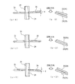
- FIG. 2 schematically shows the meshing state of the teeth 22 and 23 when the gear shafts 20 and 21 are misaligned and the meshing state of the teeth 22 and 23 when the gear shafts 20 and 21 are not misaligned.
- FIG. 2A-1 shows a state where the gear shaft 20 of the helical gear 24 on the driving side is assembled with being shifted by ⁇ with respect to the gear shaft 21 of the helical gear 25 on the driven side.
- FIG. 2A-2 shows a state where the teeth 22 of the helical gear 24 on the driving side and the teeth 23 of the helical gear 25 on the driven side in FIG. 2A-1 are engaged.
- FIG. 2A-1 shows a state where the gear shaft 20 of the helical gear 24 on the driving side is assembled with being shifted by ⁇ with respect to the gear shaft 21 of the helical gear 25 on the driven side.
- FIG. 2A-2 shows a state where the teeth 22 of the helical gear 24 on the driving side and the teeth 23 of the helical gear 25 on the
- FIG. 2B-1 shows that the gear shaft 20 of the driving side helical gear 24 is assembled without causing the gear shaft 21 of the driven side helical gear 25 to be displaced (without causing misalignment). Shows the state.
- FIG. 2B-2 shows a state where the tooth 22 of the helical gear 24 on the driving side and the tooth 23 of the helical gear 25 on the driven side in FIG.
- FIG. 2C-1 shows a state where the gear shaft 20 of the driving-side helical gear 24 is assembled with being shifted by + ⁇ with respect to the gear shaft 21 of the driven-side helical gear 25.
- FIG. 2C-2 shows a state in which the teeth 22 of the helical gear 24 on the driving side and the teeth 23 of the helical gear 25 on the driven side in FIG.
- the driving side helical 24 and the driven side helical gear 25 shown in FIGS. 2 (a-1), 2 (b-1) and 2 (c-1) clarify the difference between them. Therefore, for convenience, the tooth width of the helical gear 24 on the driving side is made smaller than the tooth width of the helical gear 25 on the driven side.
- FIG. 3 is a diagram showing a cross-sectional shape of the blade 27 of the hob 26 that is a rack-shaped tool.
- the hob 26 provided with the blade 27 shown in FIG. 3 is used for creating an electric discharge master of the injection mold of the resin helical gear 1 shown in FIG.
- the tooth tip 30 side from the position 28 corresponding to the reference pitch circle is a standard tooth profile (involute tooth profile) 31, and the tooth base 32 side from the position 28 corresponding to the reference pitch circle is a tooth tip modified surface forming part 33.
- the amount of deviation ( ⁇ ) between the extension line 31a of the standard tooth profile 31 and the tooth tip modified surface forming portion 33 at the blade base 32 is the tooth profile modification amount ⁇ 1 and the discharge.
- the electrical discharge machining master has a resin-made overall shape including a portion corresponding to the three-dimensional tooth surface modification portion 12 of the resin helical gear 1 by the hob 26 provided with the blade 27 shown in FIG. It is created into the same shape as the helical gear 1.
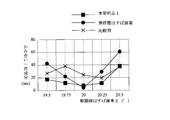
- FIG. 4 shows a state where the meshing states of the teeth 22 and 23 shown in FIGS. 2 (a-2), (b-2), and (c-2) are set and the load torque is 0.1 Nm.
- the result of measuring the primary component of meshing as a rotation transmission error of the helical gear 1 made of resin according to the first embodiment of the invention (abbreviated as product 1 of the present invention) in a one-tooth engagement test is generally used.
- the horizontal axis represents the torsion angle ⁇ of the helical gear on the drive side, which will be described later, and the vertical axis represents the meshing primary component (sec) of the rotation transmission error.
- the meshing primary component as a rotation transmission error is abbreviated as a rotation transmission error as appropriate.
- the single-tooth contact test was performed using a single-tooth contact tester (MEATA-4) manufactured by Ogasawara Precision Laboratories.
- the gear specifications of the driving-side helical gear 24 and the driven-side helical gear 25 used in this one-tooth engagement test are as follows: number of teeth (Z) 36, module (m) 0.7, pressure angle ( ⁇ ) 20 °, torsion angle ( ⁇ ) 20 °, tooth width 7 mm, parallel teeth.
- the alignment error ( ⁇ shown in FIGS. 2A and 2C) of the gear shafts 20 and 21 is 0 in consideration of the condition in which the resin helical gear 1 according to the present embodiment is used. .25 ° and 0.5 °.
- the one-tooth engagement test is performed under conditions in which the resin helical gear 1 according to the present embodiment is used (mainly used under a load torque of 0.1 to 0.25 Nm). In consideration, a load torque of 0.1 Nm, 0.2 Nm, or 0.25 Nm was applied.
- a helical gear (unmodified helical gear) made of resin (POM (equivalent to M25)) was used as the driving-side helical gear 24 having a standard tooth profile (involute tooth profile).
- the driven helical gear 25 is made of an unmodified helical gear (not shown) made of a resin (POM (equivalent to M25)) and a crowning (crowning amount 20 ⁇ m), which are used as criteria for judging whether the rotation transmission error is good or bad.
- Helical gear (comparative example) made of applied resin (POM (equivalent to M25)), helical gear 1 made of resin (POM (equivalent to M25)) according to the invention product 1, or invention products 2 to 3 described later
- One of the helical gears 1 made of resin (POM (equivalent to M25)) is used.
- the meshing state shown in FIG. 2 (c-2) is configured.
- the single-tooth surface meshing tester ensures that the inter-axis distance during the test of the gear shaft 20 of the helical gear 24 on the driving side and the gear shaft 21 of the helical gear 25 on the driven side is backlash to the theoretical inter-axis distance. For this reason, the distance is 0.25 mm.
- POM (M25) indicates grade M25 of trade name “Duracon” (registered trademark) manufactured by Polyplastics Co., Ltd.
- the product 1 of the present invention has no modification in the state where there is no alignment error (the helical angle 24 of the helical gear 24 on the driving side is 20 °).
- the rotation transmission error is almost the same as that of a gear.
- the product 1 of the present invention is in a state where there is an alignment error (when the helical angle 24 of the helical gear 24 on the drive side is 19.5 °, 19.75 °, 20.25 °, 20.5 °). If the rotation transmission error is not modified, it is smaller than that of the helical gear, and the effect of the tooth profile modification is significant.
- the product 1 of the present invention can reduce the variation of the rotation transmission error with respect to the alignment error (can improve the robustness) as compared with the unmodified helical gear.
- the variation of the rotation transmission error with respect to the alignment error can be reduced (the robustness can be increased) as compared with the unmodified helical gear, but there is no alignment error (the driving side is the helical gear 24).
- the rotation transmission error is large (bad) when the twist angle ⁇ is 20 ° and when there is an alignment error (when the twist angle ⁇ of the helical gear 24 on the drive side is 19.75 °).
- the product 1 of the present invention has the same rotation transmission error when the torsion angle ⁇ of the helical gear 24 on the driving side is 20.5 °, but the torsion angle of the helical gear 24 on the driving side.
- the rotation transmission error is small when ⁇ is 19.5 ° to 20.25 °.
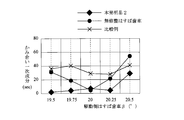
- FIG. 5 shows a state where the meshing states of the teeth 22 and 23 shown in FIGS. 2 (a-2), (b-2), and (c-2) are set and the load torque is 0.2 Nm.
- the result of measuring the primary component of meshing as a rotation transmission error of the helical gear 1 made of resin according to the second embodiment of the invention (abbreviated as product 2 of the present invention) in a one-tooth engagement test is generally used.
- the horizontal axis represents the torsion angle ⁇ of the helical gear on the driving side
- the vertical axis represents the meshing primary component (sec) of the rotation transmission error.
- the product 2 of the present invention has no modification in the state where there is no alignment error (the helical angle 24 of the helical gear 24 on the driving side is 20 °).
- the rotation transmission error is almost the same as that of a gear.
- there is an alignment error (when the helical angle 24 of the driving side helical gear 24 is 19.5 °, 19.75 °, 20.25 °, 20.5 °). If the rotation transmission error is not modified, it is smaller than that of the helical gear, and the effect of the tooth profile modification is significant.
- the product 2 of the present invention can reduce the variation of the rotation transmission error with respect to the alignment error as compared with the unmodified helical gear (can increase the robustness).
- the comparative example can reduce the variation of the rotation transmission error with respect to the alignment error compared to the unmodified helical gear (it can increase the robustness)
- the helical angle 24 of the helical gear 24 is 19 on the driving side.
- the rotation transmission error is large (bad) in the range of 5 ° to 20.25 °.
- the product 2 of the present invention can reduce the rotation transmission error regardless of the presence or absence of the alignment error.
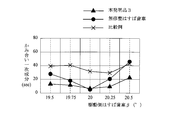
- FIG. 6 shows a state in which the meshing states of the teeth 22 and 23 shown in FIGS. 2 (a-2), (b-2), and (c-2) are set, and the load torque is 0.25 Nm. It is generally used as a result of measuring a primary component of meshing as a rotation transmission error of a helical gear 1 made of resin according to a third embodiment of the invention (abbreviated as product 3 of the present invention) in a one-tooth engagement test.
- product 3 of the present invention abbreviated as product 3 of the present invention
- the horizontal axis represents the helical angle ⁇ of the helical gear on the driving side
- the vertical axis represents the meshing primary component (sec) of the rotation transmission error.
- the product 3 of the present invention has no modification in the state where there is no alignment error (the helical angle 24 of the helical gear 24 on the driving side is 20 °).
- the rotation transmission error is almost the same as that of a gear.
- there is an alignment error (when the torsion angle ⁇ of the helical gear 24 on the driving side is 19.5 °, 19.75 °, 20.25 °, 20.5 °). If the rotation transmission error is not modified, it is smaller than that of the helical gear, and the effect of the tooth profile modification is significant.
- the product 3 of the present invention can reduce the variation of the rotation transmission error with respect to the alignment error (can improve the robustness) as compared with the unmodified helical gear.
- the comparative example can reduce the variation of the rotation transmission error with respect to the alignment error compared to the unmodified helical gear (it can increase the robustness)
- the helical angle 24 of the helical gear 24 is 19 on the driving side.
- the rotation transmission error is large (bad) in the range of 5 ° to 20.25 °.
- the product 3 of the present invention rotates regardless of the presence or absence of an alignment error (when the torsion angle ⁇ of the helical gear 24 on the driving side is in the range of 19.5 ° to 20.5 °). Transmission error can be reduced.
- the resin helical gear 1 according to the present embodiment (the products 1 to 3 of the present invention) is used under the main use conditions (the load torque is 0.1 to 0.25 Nm).
- the load torque is 0.1 to 0.25 Nm.
- the rotation transmission error due to misalignment of the gear shafts 20 and 21 is reduced, and even when the gear shafts 20 and 21 are misaligned.
- the rotation transmission accuracy can be improved.
- the products 1 to 3 of the present invention have an alignment error compared to a resin helical gear that is not subjected to tooth profile modification under the main usage conditions (when the load torque is 0.1 to 0.25 Nm).
- the variation in rotation transmission error with respect to can be reduced (robustness can be increased), and stable rotation transmission can be achieved.
- the resin helical gear 1 according to the present embodiment has a tooth width of the tooth tip modification surface 16 as the load torque increases, as is apparent from the results of the one-tooth engagement test shown in FIGS.
- the tooth profile modification amount ⁇ 1 at the tooth tip 13 at the center in the direction is increased, or the tooth profile modification amount ⁇ 1 at the tooth tip 13 at the center in the tooth width direction of the tooth tip modification surface 16 is increased and both ends of the arc crowning surface 18 in the tooth width direction are increased.
- By increasing the tooth profile modification amount ⁇ 2 at there is a tendency to produce a favorable effect (an effect of reducing rotation transmission error and increasing robustness) according to the load torque.
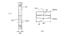
- FIG. 7 is a view showing a meshing state of the driving-side helical gear 24 and the driven-side helical gear 25 according to the embodiment.
- FIG. 7 (a) is a diagram showing the meshing state of the helical gears 24 and 25 having the same tooth width W1
- FIG. 7 (b) is a diagram of the meshed teeth 22 and 23 of FIG. 7 (a). It is a figure which expands and shows.
- the tooth 22 of the helical gear 24 on the driving side and the tooth 23 of the helical gear 25 on the driven side are formed to have the same tooth width W1.
- the crowning vertex position P ⁇ b> 1 is located at the center CL ⁇ b> 1 of the tooth 23 in the tooth width direction.
- the resin helical gear 1 (driven side helical gear 25) according to the present invention is not limited to the embodiment shown in FIG. 7, but as shown in FIG.
- the helical gear 25a has a configuration in which the small-diameter helical gear 25a meshes with the driving-side helical gear 24, the small-diameter helical gear 25a has a tooth width W3 of the teeth 23 of the helical gear 25a and the driving-side helical gear. Since the tooth width W2 of the 24 teeth 22 is different (W3> W2), the crowning apex position P2 is formed at the center CL2 of the effective tooth width W2 that meshes with the helical gear 24 on the driving side.
- the start position of the tooth tip modification surface 16 is on the reference pitch circle 15, but the present invention is not limited to this, and the start position of the tooth tip modification surface 16 is the reference pitch. It may be shifted from the circle 15 toward the tooth tip 13 or the tooth root 14. Further, in the resin helical gear 1 according to the present embodiment, the vertex position of the arc crowning surface 18 is the center of the tooth 2 in the width direction of the tooth 2, but the present invention is not limited to this, and the vertex position of the arc crowning surface 18 is determined. The tooth 2 may be shifted toward one end in the tooth width direction or the other end of the tooth 2 in the tooth width direction.
- FIG. 9 is a simplified view of the toner cartridge 34 to which the resin helical gear 1 according to the present invention is rotatably attached.
- the toner cartridge 34 shown in FIG. 9 is detachably attached to an image forming apparatus 35 (a printer, a copier, a facsimile machine, a complex machine thereof, etc.), and the toner cartridge in the image forming apparatus main body 36 is provided.
- the helical gear 1 (25) made of resin according to the present invention meshes with the helical gear 24 attached to the image forming apparatus main body 36 side, and the helical side gear on the driving side.
- the rotation of 24 is transmitted to the other gears 38 and 40.
- the resin helical gear 1 according to the present invention is not limited to the case of being attached to the toner cartridge 34, and can be widely used in other power transmission parts of the image forming apparatus 35, automobile parts, precision machines, and the like. it can.
Landscapes
- Engineering & Computer Science (AREA)
- General Engineering & Computer Science (AREA)
- Mechanical Engineering (AREA)
- Physics & Mathematics (AREA)
- Electromagnetism (AREA)
- Thermal Sciences (AREA)
- Gears, Cams (AREA)
- Electrophotography Configuration And Component (AREA)
Abstract
歯車軸のミスアライメントに起因する回転伝達誤差を減少させることができる回転伝達精度の良い樹脂製はすば歯車を提供する。インボリュート歯形形状の歯(2)の歯面(11)に三次元的歯面修整部分(12)を有する樹脂製はすば歯車(1)において、歯面(11)の三次元的歯面修整部分(12)は、歯先修整面(16)と円弧クラウニング面(18)との合成面である。そして、歯先修整面(16)は、歯先(13)と歯元(14)の間の位置から歯先に向けて歯厚を漸減させるようになっている。また、円弧クラウニング面(18)は、歯幅方向一端と歯幅方向他端の間の位置から歯幅方向両端に向けて歯厚を漸減させるようになっている。歯先修整面(16)の開始位置と円弧クラウニング面(18)の頂点位置との交点P0から歯元(14)まで延びる線(L1)は、インボリュート歯形形状の歯(2)の歯面(11)上の線に一致する。
Description
この発明は、回転伝達に使用される樹脂製はすば歯車に関し、特に歯車軸のミスアライメントに起因する回転伝達誤差の減少を目的として歯形修整が施された樹脂製はすば歯車に関するものである。
従来から、はすば歯車を使用した動力伝達装置の技術分野において、歯車軸のミスアライメントに起因する回転伝達誤差を減少させる様々な技術が開発されてきた。例えば、はすば歯車は、歯当たりを歯幅中央部に集中させるために、歯すじ方向に適当なふくらみをつけるような加工(クラウニング)を施し、歯車軸のミスアライメントに起因する回転伝達誤差を減少させるようにした技術が知られている(特許文献1、2参照)。
しかしながら、上記従来のクラウニングを施した樹脂製はすば歯車は、歯車軸のミスアライメントに起因する回転伝達誤差を十分に減少させることができなかった。
そこで、本発明は、歯車軸のミスアライメントに起因する回転伝達誤差を減少させることができる回転伝達精度の良い樹脂製はすば歯車を提供する。
本発明は、インボリュート歯形形状の歯2の歯面11に三次元的歯面修整部分12を有する樹脂製はすば歯車1に関するものである。この発明において、前記歯面11の三次元的歯面修整部分12は、歯先13と歯元14の間の位置から歯先13に向けて歯厚を漸減させる歯先修整面16と、歯幅方向一端と歯幅方向他端の間の位置から歯幅方向両端に向けて歯厚を漸減させる円弧クラウニング面18と、の合成面である。そして、前記インボリュート歯形形状の歯2の歯面11は、前記歯先修整面16の開始位置と前記円弧クラウニング面18の頂点位置との交点P0から歯元14まで延びる線L1として残っている。
本発明に係る樹脂製はすば歯車は、歯形修整を施さない樹脂製はすば歯車と比較し、歯車軸のミスアライメントに起因する回転伝達誤差を減少させ、歯車軸のミスアライメントがあった場合でも回転伝達精度を向上させることができる。また、本発明に係る樹脂製はすば歯車は、歯形修整を施さない樹脂製はすば歯車と比較し、アライメント誤差に対する回転伝達誤差のばらつきを小さくできる(ロバスト性を高くすることができる)。
以下、本発明の実施形態を図面に基づき詳述する。
図1は、本発明の実施形態に係る樹脂製はすば歯車1を示す図である。なお、図1(a)は、本実施形態に係る樹脂製はすば歯車1の正面図である。また、図1(b)は、図1(a)のA1-A1線に沿って切断して示す樹脂製はすば歯車1の断面図である。また、図1(c)は、本実施形態に係る樹脂製はすば歯車1の歯2を斜め上方から見て示す斜視図である。
この図1に示すように、樹脂製はすば歯車1は、軸に嵌合される軸穴3が形成された円筒状のボス4と、このボス4の外周面4aから径方向外方へ延びる円板状のウェブ5と、このウェブ5の外周端に形成された円筒状のリム6と、リム6の外周側に複数形成された歯2と、を有している。また、この樹脂製はすば歯車1は、ボス4の外周面4aとリム6の内周面6aとを接続するウェブ5がボス4の中心軸7に沿った中央部に位置している。また、この樹脂製はすば歯車1は、中心軸7に直交する第1の仮想平面8上に、ボス4の一方の側面4b(図1(b)における左側面)、リム6の一方の側面6b(図1(b)における左側面)、及び歯2の歯幅方向の一端面2a(図1(b)における左側端面)が位置するように形成されている。また、この樹脂製はすば歯車1は、中心軸7に直交し且つ第1の仮想平面8と平行の第2の仮想平面10上に、ボス4の他方の側面4c(図1(b)における右側面)、リム6の他方の側面6c(図1(b)における右側面)、及び歯2の歯幅方向の他端面2b(図1(b)における右側端面)が位置するように形成されている。そして、このような樹脂製はすば歯車1は、ポリアセタール(POM)、ポリアミド(PA)等のプラスチックを使用して形作られている。
図1(c)に示す樹脂製はすば歯車1の歯2は、インボリュート歯形形状(標準歯形形状)の歯2の両歯面11,11に三次元的歯面修整を施すことによって形成されている。すなわち、本実施形態の樹脂製はすば歯車1において、歯面11の三次元的歯面修整部分12は、歯先13と歯元14の間の歯面11上の位置(基準ピッチ円15上の点P0を通る歯幅方向の線分)L0から歯先13に向けて歯厚を漸減させる歯先修整面16と、歯幅方向一端と歯幅方向他端の間の歯面11上の位置(歯幅方向中央に位置し且つ歯先13から歯元14に向かう歯面11上の線分17)から前記歯幅方向両端に向けて歯厚を漸減させる円弧クラウニング面18と、の合成面になっている。そして、インボリュート歯形形状の歯2の歯面11は、歯先修整面16の開始位置と円弧クラウニング面18の頂点位置との交点P0(基準ピッチ円上の点で且つ歯幅方向中央の点)から歯元14の歯幅方向中央(P1)まで延びる線L1として残っている。また、この樹脂製はすば歯車1は、歯先修整面16の歯先13における歯形修整量をΔ1とし、円弧クラウニング面18の歯幅方向両端における歯形修整量をΔ2とすると、歯先13で且つ歯幅方向両端における歯形修整量Δ3がΔ1とΔ2の和(Δ1+Δ2)となる。なお、この図1(c)に基づく樹脂製はすば歯車1の歯2の説明は、歯2の両歯面11,11が同様に三次元的歯面修整を施されたものであるため、両歯面11,11のうちの一方について詳述し、両歯面11,11のうちの他方については省略した。
図2は、歯車軸20,21にミスアライメントが生じた場合の歯22,23の噛み合い状態と、歯車軸20,21にミスアライメントが生じない場合の歯22,23の噛み合い状態とを模式的に示す図である。なお、図2(a-1)は、駆動側はすば歯車24の歯車軸20が被動側はすば歯車25の歯車軸21に対して-θだけずれて組み付けられた状態を示している。そして、図2(a-2)は、図2(a-1)における駆動側はすば歯車24の歯22と被動側はすば歯車25の歯23の噛み合い状態を示している。また、図2(b-1)は、駆動側はすば歯車24の歯車軸20が被動側はすば歯車25の歯車軸21にずれを生じることなく(ミスアライメントを生じることなく)組み付けられた状態を示している。そして、図2(b-2)は、図2(b-1)における駆動側はすば歯車24の歯22と被動側はすば歯車25の歯23の噛み合い状態を示している。また、図2(c-1)は、駆動側はすば歯車24の歯車軸20が被動側はすば歯車25の歯車軸21に対して+θだけずれて組み付けられた状態を示している。そして、図2(c-2)は、図2(c-1)における駆動側はすば歯車24の歯22と被動側はすば歯車25の歯23の噛み合い状態を示している。また、図2(a-1)、図2(b-1)及び図2(c-1)に示す駆動側はすば24と被動側はすば歯車25は、両者の違いを明確にするため、便宜的に駆動側はすば歯車24の歯幅を被動側はすば歯車25の歯幅よりも小さくしてある。
図3は、ラック形工具であるホブ26の刃27の断面形状を示す図である。この図3に示す刃27を備えたホブ26は、図1に示した樹脂製はすば歯車1の射出成形用金型の放電加工用マスタを創成加工するために使用されるものであり、基準ピッチ円に対応する位置28から刃先30側が標準歯形部(インボリュート歯形部)31であって、基準ピッチ円に対応する位置28から刃元32側が歯先修整面形成部33である。そして、この図3に示す刃27を備えたホブ26は、刃元32における標準歯形部31の延長線31aと歯先修整面形成部33とのずれ量(Δ)が歯形修整量Δ1及び放電加工間隙等を考慮して決定される。そして、放電加工用マスタは、図3に示す刃27を備えたホブ26によって、樹脂製はすば歯車1の三次元的歯面修整部分12に対応する部分を含めた全体形状が、樹脂製はすば歯車1と同様の形状に創成加工される。
図4は、図2(a-2)、(b-2)、(c-2)に示した歯22,23の噛み合い状態を設定し、負荷トルクが0.1Nm作用する条件下において、本発明の第1実施例に係る樹脂製はすば歯車1(本発明品1と略称する)の回転伝達誤差としてのかみ合い一次成分を片歯面噛み合い試験で測定した結果と、一般的に使用される歯面修整を施さない樹脂製はすば歯車(無修整はすば歯車)の回転伝達誤差としてのかみ合い一次成分を片歯面噛み合い試験で測定した結果と、クラウニング(クラウニング量20μm)を施した樹脂製はすば歯車(比較例)の回転伝達誤差(かみ合い一次成分)を片歯面かみ合い試験で測定した結果と、を対比して示す図である。この本発明品1は、歯先修整面16の歯幅方向中央の歯先13における歯形修整量Δ1が10μmであり、円弧クラウニング面18の歯幅方向両端における歯形修整量Δ2が10μmであり、歯先13で且つ歯幅方向両端における歯形修整量Δ3(Δ3=Δ1+Δ2)が20μmである。なお、図4において、横軸が後述する駆動側はすば歯車のねじれ角βを表し、縦軸が回転伝達誤差のうちのかみ合い一次成分(sec)を表している。また、以下の説明において、回転伝達誤差としてのかみ合い一次成分を回転伝達誤差と適宜略称する。
片歯面噛み合い試験は、株式会社小笠原プレシジョンラボラトリー製の片歯面噛み合い試験機(MEATA-4)を使用して行った。この片歯面噛み合い試験に使用される駆動側はすば歯車24及び被動側はすば歯車25の歯車諸元は、歯数(Z)36、モジュール(m)0.7、圧力角(α)20°、ねじれ角(β)20°、歯幅7mm、並歯となっている。また、歯車軸20,21のアライメント誤差(図2(a)及び図2(c)に示すθ)は、本実施形態に係る樹脂製はすば歯車1が使用される条件を考慮して0.25°と0.5°とした。また、片歯面噛み合い試験は、本実施形態に係る樹脂製はすば歯車1が使用される条件(主に、0.1~0.25Nmの負荷トルクが作用した状態で使用される)を考慮して、0.1Nm、0.2Nm、又は0.25Nmの負荷トルクを付与して行った。そして、標準歯形(インボリュート歯形)を有する駆動側はすば歯車24は、樹脂(POM(M25相当))製のはすば歯車(無修整はすば歯車)が使用された。また、被動側はすば歯車25は、回転伝達誤差の良否判断の基準となる樹脂(POM(M25相当))製の無修整はすば歯車(図示せず)、クラウニング(クラウニング量20μm)を施した樹脂(POM(M25相当))製はすば歯車(比較例)、本発明品1に係る樹脂(POM(M25相当))製はすば歯車1、又は後述する本発明品2乃至3に係る樹脂(POM(M25相当))製はすば歯車1のいずれかが使用される。なお、片歯面噛み合い試験機は、歯車軸20,21のアライメント誤差を付与できないため(駆動側はすば歯車24の歯車軸20を被動側はすば歯車25の歯車軸21に対して傾けた状態で取り付けることができない構造であるため)、基準の駆動側はすば歯車24(β=20°)を歯22のねじれ角(β)が19.5°(θ=0.5°)と19.75°(θ=0.25°)の駆動側はすば歯車24に代えることにより、図2(a-2)に示す噛み合い状態を構成し、また、基準の駆動側はすば歯車24(β=20°)を歯22のねじれ角(β)が20.25°(θ=0.25°)と20.5°(θ=0.5°)の駆動側はすば歯車24に代えることにより、図2(c-2)に示す噛み合い状態を構成するようになっている。また、片歯面噛み合い試験機は、駆動側はすば歯車24の歯車軸20と被動側はすば歯車25の歯車軸21の試験時の軸間距離が、理論軸間距離にバックラッシ確保のための0.25mmを加えた距離になっている。ここで、POM(M25)は、ポリプラスチックス株式会社製の商品名「ジュラコン」(登録商標)のグレードM25を示している。
図4に示す片歯面噛み合い試験の結果によれば、本発明品1は、アライメント誤差が無い状態(駆動側はすば歯車24のねじれ角βが20°の状態)において、無修整はすば歯車とほぼ同等の回転伝達誤差である。また、本発明品1は、アライメント誤差がある状態(駆動側はすば歯車24のねじれ角βが19.5°、19.75°、20.25°、20.5°の状態)において、回転伝達誤差が無修整はすば歯車よりも小さく、歯形修整の効果が大きく現れている。また、本発明品1は、無修整はすば歯車と比較して、アライメント誤差に対する回転伝達誤差のばらつきを小さくできる(ロバスト性を高くすることができる)。比較例は、無修整はすば歯車と比較し、アライメント誤差に対する回転伝達誤差のばらつきを小さくできる(ロバスト性を高くすることができる)ものの、アライメント誤差が無い状態(駆動側はすば歯車24のねじれ角βが20°の状態)及びアライメント誤差がある状態(駆動側はすば歯車24のねじれ角βが19.75°の状態)で回転伝達誤差が大きく(悪く)なっている。このような比較例に対し、本発明品1は、駆動側はすば歯車24のねじれ角βが20.5°で同等の回転伝達誤差であるが、駆動側はすば歯車24のねじれ角βが19.5°~20.25°で回転伝達誤差が小さくなっている。
図5は、図2(a-2)、(b-2)、(c-2)に示した歯22,23の噛み合い状態を設定し、負荷トルクが0.2Nm作用する条件下において、本発明の第2実施例に係る樹脂製はすば歯車1(本発明品2と略称する)の回転伝達誤差としてのかみ合い一次成分を片歯面噛み合い試験で測定した結果と、一般的に使用される歯面修整を施さない樹脂製はすば歯車(無修整はすば歯車)の回転伝達誤差としてのかみ合い一次成分を片歯面噛み合い試験で測定した結果と、クラウニング(クラウニング量20μm)を施した樹脂製はすば歯車(比較例)の回転伝達誤差(かみ合い一次成分)を片歯面かみ合い試験で測定した結果と、を対比して示す図である。この本発明品2は、歯先修整面16の歯幅方向中央の歯先13における歯形修整量Δ1が20μmであり、円弧クラウニング面18の歯幅方向両端における歯形修整量Δ2が10μmであり、歯先13で且つ歯幅方向両端における歯形修整量Δ3(Δ3=Δ1+Δ2)が30μmである。なお、図5において、横軸が駆動側はすば歯車のねじれ角βを表し、縦軸が回転伝達誤差のうちのかみ合い一次成分(sec)を表している。
図5に示す片歯面噛み合い試験の結果によれば、本発明品2は、アライメント誤差が無い状態(駆動側はすば歯車24のねじれ角βが20°の状態)において、無修整はすば歯車とほぼ同等の回転伝達誤差である。また、本発明品2は、アライメント誤差がある状態(駆動側はすば歯車24のねじれ角βが19.5°、19.75°、20.25°、20.5°の状態)において、回転伝達誤差が無修整はすば歯車よりも小さく、歯形修整の効果が大きく現れている。また、本発明品2は、無修整はすば歯車と比較して、アライメント誤差に対する回転伝達誤差のばらつきを小さくできる(ロバスト性を高くすることができる)。比較例は、無修整はすば歯車と比較し、アライメント誤差に対する回転伝達誤差のばらつきを小さくできる(ロバスト性を高くすることができる)ものの、駆動側はすば歯車24のねじれ角βが19.5°~20.25°の状態で回転伝達誤差が大きく(悪く)なっている。このような比較例に対し、本発明品2は、アライメント誤差の有無にかかわらず、回転伝達誤差を小さくすることができる。
図6は、図2(a-2)、(b-2)、(c-2)に示した歯22,23の噛み合い状態を設定し、負荷トルクが0.25Nm作用する条件下において、本発明の第3実施例に係る樹脂製はすば歯車1(本発明品3と略称する)の回転伝達誤差としてのかみ合い一次成分を片歯面噛み合い試験で測定した結果と、一般的に使用される歯面修整を施さない樹脂製はすば歯車(無修整はすば歯車)の回転伝達誤差としてのかみ合い一次成分を片歯面噛み合い試験で測定した結果と、クラウニング(クラウニング量20μm)を施した樹脂製はすば歯車(比較例)の回転伝達誤差(かみ合い一次成分)を片歯面かみ合い試験で測定した結果と、を対比して示す図である。この本発明品3は、歯先修整面16の歯幅方向中央の歯先13における歯形修整量Δ1が20μmであり、円弧クラウニング面18の歯幅方向両端における歯形修整量Δ2が20μmであり、歯先13で且つ歯幅方向両端における歯形修整量Δ3(Δ3=Δ1+Δ2)が40μmである。なお、図6において、横軸が駆動側はすば歯車のねじれ角βを表し、縦軸が回転伝達誤差のうちのかみ合い一次成分(sec)を表している。
図6に示す片歯面噛み合い試験の結果によれば、本発明品3は、アライメント誤差が無い状態(駆動側はすば歯車24のねじれ角βが20°の状態)において、無修整はすば歯車とほぼ同等の回転伝達誤差である。また、本発明品3は、アライメント誤差がある状態(駆動側はすば歯車24のねじれ角βが19.5°、19.75°、20.25°、20.5°の状態)において、回転伝達誤差が無修整はすば歯車よりも小さく、歯形修整の効果が大きく現れている。また、本発明品3は、無修整はすば歯車と比較して、アライメント誤差に対する回転伝達誤差のばらつきを小さくできる(ロバスト性を高くすることができる)。比較例は、無修整はすば歯車と比較し、アライメント誤差に対する回転伝達誤差のばらつきを小さくできる(ロバスト性を高くすることができる)ものの、駆動側はすば歯車24のねじれ角βが19.5°~20.25°の状態で回転伝達誤差が大きく(悪く)なっている。このような比較例に対し、本発明品3は、アライメント誤差の有無にかかわらず(駆動側はすば歯車24のねじれ角βが19.5°~20.5°の範囲内において)、回転伝達誤差を小さくすることができる。
以上の説明から明らかなように、本実施形態に係る樹脂製はすば歯車1(本発明品1~3)は、主に使用される条件下(負荷トルクが0.1~0.25Nmの場合)において、歯形修整を施さない樹脂製はすば歯車と比較し、歯車軸20,21のミスアライメントに起因する回転伝達誤差を減少させ、歯車軸20,21のミスアライメントがあった場合でも回転伝達精度を向上させることができる。また、本発明品1~3は、主に使用される条件下(負荷トルクが0.1~0.25Nmの場合)において、歯形修整を施さない樹脂製はすば歯車と比較し、アライメント誤差に対する回転伝達誤差のばらつきを小さくでき(ロバスト性を高くすることができ)、安定した回転伝達を可能にする。
なお、本実施形態に係る樹脂製はすば歯車1は、図4乃至図6の片歯面噛み合い試験の結果から明らかなように、負荷トルクの増加にしたがって、歯先修整面16の歯幅方向中央の歯先13における歯形修整量Δ1を増加させるか、又は、歯先修整面16の歯幅方向中央の歯先13における歯形修整量Δ1を増加させると共に円弧クラウニング面18の歯幅方向両端における歯形修整量Δ2を増加させることによって、負荷トルクに応じた好ましい効果(回転伝達誤差を減少させ、ロバスト性を高くする効果)を生じる傾向がある。
(変形例1)
図7は、上記実施形態に係る駆動側はすば歯車24と被動側はすば歯車25の噛み合い状態を示す図である。なお、図7(a)は歯幅W1が同一のはすば歯車24,25同士のかみ合い状態を示す図であり、図7(b)は図7(a)のかみ合った歯22,23同士を拡大して示す図である。
この図7に示すように、駆動側はすば歯車24の歯22と被動側はすば歯車25(本発明品1~3)の歯23は、歯幅W1が同一に形成されており、クラウニングの頂点位置P1が歯23の歯幅方向中央CL1に位置している。
しかしながら、本発明に係る樹脂製はすば歯車1(被動側はすば歯車25)は、図7に示す実施態様に限定されるものでなく、図8に示すように、2段歯車の小径はすば歯車25aであって、この小径はすば歯車25aが駆動側はすば歯車24と噛み合う構成の場合、小径はすば歯車25aの歯23の歯幅W3と駆動側はすば歯車24の歯22の歯幅W2とが異なる(W3>W2)ため、クラウニングの頂点位置P2が駆動側はすば歯車24と噛み合う有効歯幅W2の中央CL2に位置するように形成される。
図7は、上記実施形態に係る駆動側はすば歯車24と被動側はすば歯車25の噛み合い状態を示す図である。なお、図7(a)は歯幅W1が同一のはすば歯車24,25同士のかみ合い状態を示す図であり、図7(b)は図7(a)のかみ合った歯22,23同士を拡大して示す図である。
この図7に示すように、駆動側はすば歯車24の歯22と被動側はすば歯車25(本発明品1~3)の歯23は、歯幅W1が同一に形成されており、クラウニングの頂点位置P1が歯23の歯幅方向中央CL1に位置している。
しかしながら、本発明に係る樹脂製はすば歯車1(被動側はすば歯車25)は、図7に示す実施態様に限定されるものでなく、図8に示すように、2段歯車の小径はすば歯車25aであって、この小径はすば歯車25aが駆動側はすば歯車24と噛み合う構成の場合、小径はすば歯車25aの歯23の歯幅W3と駆動側はすば歯車24の歯22の歯幅W2とが異なる(W3>W2)ため、クラウニングの頂点位置P2が駆動側はすば歯車24と噛み合う有効歯幅W2の中央CL2に位置するように形成される。
(変形例2)
本実施形態に係る樹脂製はすば歯車1は、歯先修整面16の開始位置が基準ピッチ円15上になっているが、これに限られず、歯先修整面16の開始位置を基準ピッチ円15上から歯先13寄り又は歯元14寄りにずらしても良い。また、本実施形態に係る樹脂製はすば歯車1は、円弧クラウニング面18の頂点位置が歯2の歯幅方向中央になっているが、これに限られず、円弧クラウニング面18の頂点位置を歯2の歯幅方向一端寄り又は歯2の歯幅方向他端寄りにずらしても良い。
本実施形態に係る樹脂製はすば歯車1は、歯先修整面16の開始位置が基準ピッチ円15上になっているが、これに限られず、歯先修整面16の開始位置を基準ピッチ円15上から歯先13寄り又は歯元14寄りにずらしても良い。また、本実施形態に係る樹脂製はすば歯車1は、円弧クラウニング面18の頂点位置が歯2の歯幅方向中央になっているが、これに限られず、円弧クラウニング面18の頂点位置を歯2の歯幅方向一端寄り又は歯2の歯幅方向他端寄りにずらしても良い。
(応用例)
図9は、本発明に係る樹脂製はすば歯車1が回動可能に取り付けられたトナーカートリッジ34を簡略化して示す図である。この図9に示すトナーカートリッジ34は、画像形成装置35(プリンタ、複写機、ファクシミリ装置、これらの複合機等)に着脱可能に取り付けられるようになっており、画像形成装置本体36内のトナーカートリッジ収容スペース37に収容されると、本発明に係る樹脂製はすば歯車1(25)が画像形成装置本体36側に取り付けられた駆動側はすば歯車24と噛み合い、駆動側はすば歯車24の回転を他の歯車38,40に伝達するようになっている。
なお、本発明に係る樹脂製はすば歯車1は、トナーカートリッジ34に取り付けられる場合に限定されず、画像形成装置35の他の動力伝達部分、自動車部品、精密機械等に広く使用することができる。
図9は、本発明に係る樹脂製はすば歯車1が回動可能に取り付けられたトナーカートリッジ34を簡略化して示す図である。この図9に示すトナーカートリッジ34は、画像形成装置35(プリンタ、複写機、ファクシミリ装置、これらの複合機等)に着脱可能に取り付けられるようになっており、画像形成装置本体36内のトナーカートリッジ収容スペース37に収容されると、本発明に係る樹脂製はすば歯車1(25)が画像形成装置本体36側に取り付けられた駆動側はすば歯車24と噛み合い、駆動側はすば歯車24の回転を他の歯車38,40に伝達するようになっている。
なお、本発明に係る樹脂製はすば歯車1は、トナーカートリッジ34に取り付けられる場合に限定されず、画像形成装置35の他の動力伝達部分、自動車部品、精密機械等に広く使用することができる。
1……樹脂製はすば歯車、2……歯、11……歯面、12……三次元的歯面修整部分、13……歯先、14……歯元、16……歯先修整面、18……円弧クラウニング面、P0……交点、L1……線
Claims (5)
- インボリュート歯形形状の歯の歯面に三次元的歯面修整部分を有する樹脂製はすば歯車において、
前記歯面の三次元的歯面修整部分は、歯先と歯元の間の位置から歯先に向けて歯厚を漸減させる歯先修整面と、歯幅方向一端と歯幅方向他端の間の位置から前記歯幅方向両端に向けて歯厚を漸減させる円弧クラウニング面と、の合成面であり、
前記インボリュート歯形形状の歯の歯面は、前記歯先修整面の開始位置と前記円弧クラウニング面の頂点位置との交点から歯元まで延びる線として残っている、
ことを特徴とする樹脂製はすば歯車。 - 前記歯先修整面の開始位置は基準ピッチ円であり、前記円弧クラウニング面の頂点位置は歯幅方向中央である、
ことを特徴とする請求項1に記載の樹脂製はすば歯車。 - 前記歯先修整面の前記歯先における歯形修整量をΔ1とし、
前記円弧クラウニング面の前記歯幅方向両端における歯形修整量をΔ2とすると、
前記歯先で且つ前記歯幅方向両端における歯形修整量Δ3は、Δ1+Δ2となる、
ことを特徴とする請求項2に記載の樹脂製はすば歯車。 - 前記歯先修正面の開始位置は基準ピッチ円であり、前記円弧クラウニング面の頂点位置は有効歯幅の中央である、
ことを特徴とする請求項1に記載の樹脂製はすば歯車。 - 画像形成装置本体側に取り付けられた駆動側はすば歯車と噛み合う被動側はすば歯車を回動可能に有するトナーカートリッジにおいて、
前記被動側はすば歯車は、前記請求項1に記載の樹脂製はすば歯車である、
ことを特徴とするトナーカートリッジ。
Priority Applications (2)
| Application Number | Priority Date | Filing Date | Title |
|---|---|---|---|
| CN201680055328.0A CN108138936B (zh) | 2015-09-29 | 2016-07-26 | 树脂制斜齿轮 |
| US15/764,074 US10816076B2 (en) | 2015-09-29 | 2016-07-26 | Plastic helical gear |
Applications Claiming Priority (2)
| Application Number | Priority Date | Filing Date | Title |
|---|---|---|---|
| JP2015-190700 | 2015-09-29 | ||
| JP2015190700A JP6560578B2 (ja) | 2015-09-29 | 2015-09-29 | 樹脂製はすば歯車 |
Publications (1)
| Publication Number | Publication Date |
|---|---|
| WO2017056659A1 true WO2017056659A1 (ja) | 2017-04-06 |
Family
ID=58423430
Family Applications (1)
| Application Number | Title | Priority Date | Filing Date |
|---|---|---|---|
| PCT/JP2016/071801 Ceased WO2017056659A1 (ja) | 2015-09-29 | 2016-07-26 | 樹脂製はすば歯車 |
Country Status (4)
| Country | Link |
|---|---|
| US (1) | US10816076B2 (ja) |
| JP (1) | JP6560578B2 (ja) |
| CN (1) | CN108138936B (ja) |
| WO (1) | WO2017056659A1 (ja) |
Families Citing this family (8)
| Publication number | Priority date | Publication date | Assignee | Title |
|---|---|---|---|---|
| US20180291997A1 (en) * | 2017-04-10 | 2018-10-11 | Caterpillar Global Mining Llc | Gear tooth geometry for crowd gear assembly on rope shovel |
| JP2019211076A (ja) * | 2018-05-30 | 2019-12-12 | キヤノン株式会社 | 駆動伝達装置及び画像形成装置 |
| CN109899481B (zh) * | 2019-03-22 | 2024-05-28 | 中南大学 | 一种斜齿轮及具有该斜齿轮的传动机构 |
| US11022921B2 (en) | 2019-04-10 | 2021-06-01 | Ricoh Company, Ltd. | Image forming apparatus |
| CN111136423B (zh) * | 2019-12-25 | 2022-05-24 | 山西太钢鑫磊资源有限公司 | 一种弓形齿板齿牙磨损的修整方法 |
| CN112728011A (zh) * | 2020-12-25 | 2021-04-30 | 中国船舶重工集团公司第七0三研究所 | 一种用于对构斜齿轮传动性能测试的齿轮传动结构 |
| US11054013B1 (en) * | 2021-01-08 | 2021-07-06 | Enplas Corporation | Profile modification for planetary gear device gear teeth |
| IT202200017307A1 (it) * | 2022-08-12 | 2024-02-12 | Gen Electric | Gruppo trasmissione |
Citations (3)
| Publication number | Priority date | Publication date | Assignee | Title |
|---|---|---|---|---|
| JPH0422799A (ja) * | 1990-05-16 | 1992-01-27 | Daikin Ind Ltd | ターボ圧縮機の増速装置 |
| JPH1089442A (ja) * | 1996-09-18 | 1998-04-07 | Kawasaki Heavy Ind Ltd | 3次元歯面修整はすば/やまば歯車 |
| JP2008240793A (ja) * | 2007-03-26 | 2008-10-09 | Enplas Corp | 樹脂製歯車 |
Family Cites Families (16)
| Publication number | Priority date | Publication date | Assignee | Title |
|---|---|---|---|---|
| CH564999A5 (ja) * | 1974-03-07 | 1975-08-15 | Maag Zahnraeder & Maschinen Ag | |
| JP3786982B2 (ja) | 1995-01-19 | 2006-06-21 | トヨタ自動車株式会社 | 歯車の歯面修整方法 |
| JP2768912B2 (ja) * | 1995-04-18 | 1998-06-25 | 川崎重工業株式会社 | はすば/やまば歯車における3次元歯面修整構造 |
| JPH08312755A (ja) * | 1995-05-16 | 1996-11-26 | Matsushita Electric Ind Co Ltd | 平行軸歯車対 |
| US5802921A (en) * | 1996-08-13 | 1998-09-08 | Rouverol; William S. | Maximum power density gearing |
| US6253047B1 (en) * | 2000-03-08 | 2001-06-26 | Xerox Corporation | Printer motion quality improvement with crowned gear drive systems |
| WO2005044482A1 (en) * | 2003-11-07 | 2005-05-19 | Bishop Innovation Limited | Method and apparatus for forging gear teeth |
| JP4868893B2 (ja) * | 2005-09-28 | 2012-02-01 | 株式会社エンプラス | 歯車及び歯車装置 |
| JP5520374B2 (ja) * | 2010-06-21 | 2014-06-11 | 大岡技研株式会社 | 自由曲面歯車 |
| JP5734102B2 (ja) * | 2011-06-01 | 2015-06-10 | 株式会社ハーモニック・ドライブ・システムズ | テーパ型の可撓性外歯車を備えた波動歯車装置 |
| US9164474B2 (en) * | 2013-01-08 | 2015-10-20 | Clover Technologies Group, Llc | Toner drum gear projection |
| JP5705344B2 (ja) | 2014-02-20 | 2015-04-22 | キヤノン株式会社 | 画像形成装置 |
| CN103821905B (zh) * | 2014-03-11 | 2016-05-25 | 华中科技大学 | 一种渐开线齿轮齿廓修形方法、修形齿廓及其应用 |
| JP6448423B2 (ja) * | 2014-12-05 | 2019-01-09 | 株式会社エンプラス | 樹脂製はすば歯車 |
| CN104832623B (zh) * | 2015-06-02 | 2017-03-22 | 重庆大学 | 用于齿面扭曲消减的齿向修形曲线设计方法 |
| US20180291997A1 (en) * | 2017-04-10 | 2018-10-11 | Caterpillar Global Mining Llc | Gear tooth geometry for crowd gear assembly on rope shovel |
-
2015
- 2015-09-29 JP JP2015190700A patent/JP6560578B2/ja active Active
-
2016
- 2016-07-26 CN CN201680055328.0A patent/CN108138936B/zh active Active
- 2016-07-26 US US15/764,074 patent/US10816076B2/en active Active
- 2016-07-26 WO PCT/JP2016/071801 patent/WO2017056659A1/ja not_active Ceased
Patent Citations (3)
| Publication number | Priority date | Publication date | Assignee | Title |
|---|---|---|---|---|
| JPH0422799A (ja) * | 1990-05-16 | 1992-01-27 | Daikin Ind Ltd | ターボ圧縮機の増速装置 |
| JPH1089442A (ja) * | 1996-09-18 | 1998-04-07 | Kawasaki Heavy Ind Ltd | 3次元歯面修整はすば/やまば歯車 |
| JP2008240793A (ja) * | 2007-03-26 | 2008-10-09 | Enplas Corp | 樹脂製歯車 |
Also Published As
| Publication number | Publication date |
|---|---|
| US20180274649A1 (en) | 2018-09-27 |
| JP6560578B2 (ja) | 2019-08-14 |
| JP2017067109A (ja) | 2017-04-06 |
| CN108138936A (zh) | 2018-06-08 |
| CN108138936B (zh) | 2021-01-15 |
| US10816076B2 (en) | 2020-10-27 |
Similar Documents
| Publication | Publication Date | Title |
|---|---|---|
| JP6560578B2 (ja) | 樹脂製はすば歯車 | |
| JP6448423B2 (ja) | 樹脂製はすば歯車 | |
| JP6624904B2 (ja) | 樹脂製はすば歯車 | |
| US10253862B2 (en) | Dual-type strain wave gearing | |
| JP2009236144A (ja) | まがりばかさ歯車及び歯車装置 | |
| KR20130021326A (ko) | 기어 기구 및 기어드 모터 | |
| JP2008032161A (ja) | 円錐インボリュート歯車及び歯車対 | |
| KR101846691B1 (ko) | 차량용 디퍼렌셜 장치 | |
| WO2013140721A1 (ja) | 偏心揺動型歯車装置 | |
| JP6682228B2 (ja) | 樹脂製はすば歯車 | |
| JP5520978B2 (ja) | 駆動装置 | |
| JP2005121106A (ja) | かさ歯車 | |
| KR20180018352A (ko) | 기어 기구 및 그 제조 방법 | |
| CN107228169B (zh) | 齿轮驱动装置 | |
| WO2016088577A1 (ja) | 樹脂製はすば歯車 | |
| JP2014149046A (ja) | 樹脂製歯車 | |
| WO2013132748A1 (ja) | 偏心揺動型歯車装置 | |
| JP2009150524A (ja) | ギア構造 | |
| JP4925309B2 (ja) | 樹脂製歯車 | |
| JP2024135370A (ja) | エンコーダ、回転角度算出方法、回転角度算出プログラム | |
| JP6540520B2 (ja) | デファレンシャルのファイナルドリブンギヤ | |
| JP2017172666A (ja) | 歯車駆動装置 | |
| JP6783639B2 (ja) | ギヤードモータ | |
| JP2008115886A (ja) | 斜歯歯車 | |
| JP2024122761A (ja) | エンコーダ |
Legal Events
| Date | Code | Title | Description |
|---|---|---|---|
| 121 | Ep: the epo has been informed by wipo that ep was designated in this application |
Ref document number: 16850836 Country of ref document: EP Kind code of ref document: A1 |
|
| WWE | Wipo information: entry into national phase |
Ref document number: 15764074 Country of ref document: US |
|
| NENP | Non-entry into the national phase |
Ref country code: DE |
|
| 122 | Ep: pct application non-entry in european phase |
Ref document number: 16850836 Country of ref document: EP Kind code of ref document: A1 |