WO2017006586A1 - Dispositif d'alimentation, et système de serveur équipé de celui-ci - Google Patents
Dispositif d'alimentation, et système de serveur équipé de celui-ci Download PDFInfo
- Publication number
- WO2017006586A1 WO2017006586A1 PCT/JP2016/057516 JP2016057516W WO2017006586A1 WO 2017006586 A1 WO2017006586 A1 WO 2017006586A1 JP 2016057516 W JP2016057516 W JP 2016057516W WO 2017006586 A1 WO2017006586 A1 WO 2017006586A1
- Authority
- WO
- WIPO (PCT)
- Prior art keywords
- power supply
- power
- connection conductor
- supply device
- connection
- Prior art date
Links
- 239000004020 conductor Substances 0.000 claims abstract description 117
- 238000006243 chemical reaction Methods 0.000 claims abstract description 22
- 239000011810 insulating material Substances 0.000 claims abstract description 6
- 238000003860 storage Methods 0.000 description 56
- 238000003825 pressing Methods 0.000 description 9
- 238000010586 diagram Methods 0.000 description 8
- 238000009826 distribution Methods 0.000 description 5
- XEEYBQQBJWHFJM-UHFFFAOYSA-N Iron Chemical compound [Fe] XEEYBQQBJWHFJM-UHFFFAOYSA-N 0.000 description 4
- 230000008878 coupling Effects 0.000 description 4
- 238000010168 coupling process Methods 0.000 description 4
- 238000005859 coupling reaction Methods 0.000 description 4
- 238000003780 insertion Methods 0.000 description 4
- 230000037431 insertion Effects 0.000 description 4
- 230000002457 bidirectional effect Effects 0.000 description 3
- 238000009434 installation Methods 0.000 description 3
- 230000000630 rising effect Effects 0.000 description 3
- 238000005520 cutting process Methods 0.000 description 2
- 230000000694 effects Effects 0.000 description 2
- 230000012447 hatching Effects 0.000 description 2
- 230000017525 heat dissipation Effects 0.000 description 2
- 238000009413 insulation Methods 0.000 description 2
- 229910052742 iron Inorganic materials 0.000 description 2
- 239000000463 material Substances 0.000 description 2
- 238000000034 method Methods 0.000 description 2
- RYGMFSIKBFXOCR-UHFFFAOYSA-N Copper Chemical compound [Cu] RYGMFSIKBFXOCR-UHFFFAOYSA-N 0.000 description 1
- ATJFFYVFTNAWJD-UHFFFAOYSA-N Tin Chemical compound [Sn] ATJFFYVFTNAWJD-UHFFFAOYSA-N 0.000 description 1
- 238000005452 bending Methods 0.000 description 1
- 229910052802 copper Inorganic materials 0.000 description 1
- 239000010949 copper Substances 0.000 description 1
- 230000007423 decrease Effects 0.000 description 1
- 238000000605 extraction Methods 0.000 description 1
- 230000005484 gravity Effects 0.000 description 1
- 230000020169 heat generation Effects 0.000 description 1
- 238000007689 inspection Methods 0.000 description 1
- 238000005304 joining Methods 0.000 description 1
- 238000012423 maintenance Methods 0.000 description 1
- 239000002184 metal Substances 0.000 description 1
- 229910052751 metal Inorganic materials 0.000 description 1
- 238000005192 partition Methods 0.000 description 1
- 239000011347 resin Substances 0.000 description 1
- 229920005989 resin Polymers 0.000 description 1
- 229910001220 stainless steel Inorganic materials 0.000 description 1
- 239000010935 stainless steel Substances 0.000 description 1
Images


Classifications
-
- G—PHYSICS
- G06—COMPUTING; CALCULATING OR COUNTING
- G06F—ELECTRIC DIGITAL DATA PROCESSING
- G06F1/00—Details not covered by groups G06F3/00 - G06F13/00 and G06F21/00
- G06F1/26—Power supply means, e.g. regulation thereof
- G06F1/266—Arrangements to supply power to external peripherals either directly from the computer or under computer control, e.g. supply of power through the communication port, computer controlled power-strips
-
- H—ELECTRICITY
- H05—ELECTRIC TECHNIQUES NOT OTHERWISE PROVIDED FOR
- H05K—PRINTED CIRCUITS; CASINGS OR CONSTRUCTIONAL DETAILS OF ELECTRIC APPARATUS; MANUFACTURE OF ASSEMBLAGES OF ELECTRICAL COMPONENTS
- H05K7/00—Constructional details common to different types of electric apparatus
- H05K7/14—Mounting supporting structure in casing or on frame or rack
- H05K7/1485—Servers; Data center rooms, e.g. 19-inch computer racks
- H05K7/1488—Cabinets therefor, e.g. chassis or racks or mechanical interfaces between blades and support structures
- H05K7/1492—Cabinets therefor, e.g. chassis or racks or mechanical interfaces between blades and support structures having electrical distribution arrangements, e.g. power supply or data communications
-
- G—PHYSICS
- G06—COMPUTING; CALCULATING OR COUNTING
- G06F—ELECTRIC DIGITAL DATA PROCESSING
- G06F1/00—Details not covered by groups G06F3/00 - G06F13/00 and G06F21/00
- G06F1/16—Constructional details or arrangements
- G06F1/18—Packaging or power distribution
- G06F1/189—Power distribution
Definitions
- the present invention relates to, for example, a power supply device that supplies DC power to a server system installed in a data center, and a server system including the power supply device.
- FIG. 19 shows a schematic configuration of a conventional general server system power supply system disclosed in Patent Document 1.
- This power supply system includes an uninterruptible power supply 1 connected to an AC 400V system power supply 3 and a transformer 2 that insulates and converts the voltage of the AC power output from the uninterruptible power supply 1.
- the uninterruptible power supply 1 includes a battery 1a, an AC / DC converter 1b, and a DC / AC converter 1c.
- the battery 1a is charged by an AC / DC converter 1b that converts AC power from the system power supply 3 into DC power.
- the DC power output from the AC / DC converter 1b or the DC power discharged from the battery 1a is converted into AC power of 400V AC by the DC / AC converter 1c.
- the 400V AC power output from the DC / AC converter 1c is converted by the transformer 2 into 200V or 100V AC power. Further, the converted AC power is converted into low voltage (12 V) DC power by the power converter 5 in the server system 4.
- the power converter 5 is composed of a series circuit of an AC / DC converter 5a and a DC / DC converter 5b. This 12V DC power is supplied to a plurality of servers 4a to 4n serving as loads. The individual servers 4a to 4n in the server system operate with 12V DC power.
- a plurality of servers 4a to 4n are stored in a server rack by a predetermined number to constitute a server system.
- the power converter 5 is provided corresponding to each server system. And the power converter 5 is integrally accommodated in the server rack in which each server is accommodated.
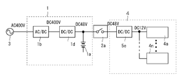
- the power supply system shown in FIG. 20 supplies high-voltage (400 V) DC power output from the AC / DC converter 1b of the uninterruptible power supply 1 to the server system 4 via the DC distribution device 2a.
- the high voltage (400V) direct current power is converted into a low voltage direct current power of 12V by the DC / DC converter 5d in the server system 4.
- This power supply system is referred to as a high voltage direct current power supply system (HVDC).
- the uninterruptible power supply 1 further includes a DC / DC converter 1d.
- the high voltage (400V) DC power output from the AC / DC converter 1b is converted into low voltage (48V) DC power by the DC / DC converter 1d.
- This low voltage (48V) DC power is supplied to the server system 4 via the DC power distribution equipment 2a.
- the low voltage (48V) DC power is further converted into low voltage (12V) DC power by the DC / DC converter 5e in the server system 4.
- This power supply system is referred to as a low voltage DC power supply system.
- the power conversion efficiency can be increased.
- a circuit breaker for cutting off high-voltage DC power is required as the DC power distribution circuit breaker 2a.
- the circuit breaker capable of interrupting high-voltage DC power is not only large, but also requires electric shock countermeasures for DC high-voltage (DC400V) distribution.
- Patent Document 1 proposes a power supply system shown in FIG.
- the power supply system shown in FIG. 22 supplies 200 V AC power supplied from the AC system power supply 3 to the server system 4.
- the server rack 40 of the server system 4 houses the uninterruptible power supply 10 and a plurality of servers 4a to 4n.
- the uninterruptible power supply 10 includes a power supply unit 20 and a battery unit 30.
- the power supply circuit unit 21 of the power supply unit 20 includes an AC / DC converter 22 that converts AC power supplied from the system power supply 3 into DC power, and DC power output from the AC / DC converter 22 to 12V DC power.
- a DC / DC converter 23 for conversion is provided. 12V DC power output from the DC / DC converter 23 is supplied to the servers 4a to 4n.
- the battery circuit unit 31 of the battery unit 30 includes a battery 32 that charges DC power and a DC / DC converter 33 that allows DC current to flow in both directions.
- the battery 32 is connected in parallel to the output of the power supply circuit unit 21 via a bidirectional DC / DC converter 33.
- the battery 32 is charged by the direct current output of the power supply circuit unit 21 through the bidirectional DC / DC converter 33 and supplies the charged direct current power to the servers 4a to 4n via the DC / DC converter 33.
- the power supply unit 20 and the battery unit 30 configured in this way are housed in a common shelf 50 as shown in FIGS. 23A and 23B to form the uninterruptible power supply 10. Yes.
- Output terminals drawn out to the back sides of the power supply unit 20 and the battery unit 30 are connected to power buses 42 and 43 in the server rack 40 via connectors 44.
- the power buses 42 and 43 are connected to a power input terminal of a server (load) 4 (not shown).
- Storing the power supply unit and the battery unit together with the server in the server rack in this way can reduce the installation space as compared with the case where the uninterruptible power supply is installed separately. Further, when the uninterruptible power supply fails, the influence is limited to only the server stored in the server rack, and does not affect the servers in other server racks. Therefore, the reliability of the server system can be improved.
- the present invention provides a power supply device that supplies DC power, the power supply device including a plurality of power conversion units that output the DC power, and output terminals of the plurality of power conversion units.
- a connection conductor module for parallel connection, a plurality of power conversion units, and a shelf for storing the connection conductor module are provided, and the connection conductor module is stored in a module case formed of an insulating material and the module case It is characterized by comprising a connecting conductor.
- the module case has an opening in a surface facing the plurality of power conversion units
- the connection conductor includes a terminal for fitting with an output terminal of the plurality of power conversion units.
- the terminal of the connection conductor is fitted and coupled to the output terminals of the plurality of power conversion units at the opening.
- the module case is composed of a first case and a second case, and the connection conductor is formed by fitting the first case and the second case into the module case. It is fixed and held inside.
- connection conductor is mounted and fixed in a holding groove provided in the first case or the second case.
- connection conductor module includes a fitting portion for fitting with a fitting portion provided on at least one of the side wall and the bottom wall of the shelf.
- connection conductor and the shelf are insulated by the module case on the upper surface, the bottom surface, and both side surfaces of the connection conductor module.
- the plurality of power conversion units that output the DC power are a power supply unit that converts the power of the AC power source into DC power and outputs the power, or a battery that converts the power of the battery into DC power and outputs the power. Is a unit.
- connection conductor includes positive and negative terminal pairs for drawing the DC power to the outside on both the left and right sides of the power supply device.
- a server power supply system can be configured by the power supply device of the present invention. In this case, it is preferable to store the power supply device in a server rack in which the server is accommodated.
- the power supply device includes a power supply unit, a battery unit, and a connection conductor module.
- the module case is detachably attached to a shelf in which the power supply unit and the battery unit are stored. And a power supply unit and a battery unit are inserted in the shelf of a power supply device, and each output terminal is electrically connected in parallel with the connection conductor of a connection conductor module.
- the connection conductor is held by a module case formed of an insulating material.
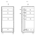
- FIG. 1A is a front sectional view
- FIG. 1B is a side sectional view.
- FIG. 2A is a front view showing a state where no unit is stored in each storage chamber of the shelf.
- FIG. 2B is a front view showing a state where the unit is stored in each storage chamber of the shelf.
- It is a perspective view which shows the state in the middle of accommodating a power supply unit and a battery unit in the shelf of an uninterruptible power supply.
- FIG. 1 It is a partial expansion perspective view which shows the insertion process of the connection conductor module in FIG. It is a perspective view which shows the completion state of the assembly of an uninterruptible power supply. It is a disassembled perspective view which shows the structure of a connection conductor module. It is the perspective view which looked at the structure of the connection conductor module from the reverse direction to FIG. It is a front view which shows the structure in the middle of the assembly of a connection conductor module. It is a perspective view which shows the state which assembled the connection conductor module. It is a perspective view which shows the external appearance of an uninterruptible power supply. (A) is a top view which expands and shows the connection terminal part of an uninterruptible power supply.
- (B) is a top view which expands and shows the A section in (a) further. It is a perspective view which shows the state which removed some cover plates of the uninterruptible power supply. It is a perspective view which shows the connection structure of the output terminal of the connection conductor module of an uninterruptible power supply device, and an extraction conductor. It is the longitudinal cross-sectional view which showed the storage state of the battery unit in the storage chamber of a shelf, (a) shows the state by which the battery unit was pulled out from the storage chamber, (b) is a battery unit just before a flapper. (C) is a diagram showing a state where the battery unit has reached the position of the flapper. It is a figure which expands and shows the A section of FIG.15 (c).
- FIG. 22 It is a figure which shows the state which the flapper in the storage chamber of a shelf closed, (a) is the top view, (b) is a perspective view which cut
- FIGS. 1 to 18 The schematic circuit configuration of the power supply system described below is the same as the schematic circuit configuration of the power supply system shown in FIG. 1 to 18, the same or equivalent elements as those in the conventional server system described with reference to FIGS. 19 to 23 are denoted by the same reference numerals.
- FIG. 1 is a diagram illustrating a schematic configuration of a server system housed in a server rack 40.
- a server rack 40 In the server rack 40, a plurality of server units 4 (a to n) and uninterruptible power supply devices 10 stacked in multiple stages are housed.
- FIG. 1A is a front view showing a part cut away in order to show the configuration inside the server rack.
- FIG. 1B is a side view with a part cut away to show the internal configuration of the server rack.
- the server rack 40 is, for example, a 19-inch rack standardized by EIA (American Electronic Industry Association).
- the uninterruptible power supply 10 includes a metal shelf 11, a power unit 20, a battery unit 30, and a connection conductor module 6 described later.
- FIG. 2A is a front view of the shelf 11 of the uninterruptible power supply 10.
- the shelf 11 is provided with a plurality of storage chambers formed by dividing the width direction into four equal parts. The left two rows of storage chambers are further divided into two upper and lower stages. Accordingly, the shelf 11 is formed with four small storage chambers 12 (ad) and two large storage chambers 13 (a, b).
- the power supply units 20 (a to d) are stored in the four small storage chambers 12 (a to d) so as to be able to be taken in and out.
- the battery unit 30 (a, b) is stored in a removable manner.
- the power supply unit 20 includes an AC / DC converter 22 and a DC / DC converter 23 as in the conventional apparatus shown in FIG.
- the AC / DC converter 22 converts AC power supplied from a commercial power supply 3 into DC power.
- the DC / DC converter 23 converts the DC power that is the output of the AC / DC converter 22 into DC power of a voltage (for example, 12V) for supplying to the server units 4 (a to n) and outputs the DC power.
- the battery unit 30 includes a battery 32 and a bidirectional DC / DC converter 33. When the power supply unit 20 is operating, the DC / DC converter 33 charges the battery 32 with the DC power output from the power supply unit 20.
- the DC / DC converter 33 discharges the direct-current power charged in the battery 32 and supplies it to the load server 4.
- the DC output unit of the power supply unit 20 and the DC output unit of the battery unit 30 are electrically connected.
- a maximum of four power supply units 20 are stored in the storage chamber 12 of the shelf 11 and a maximum of two battery units 30 are stored in the storage chamber 13.
- the number of each storage is determined by the required server power capacity.
- a DC bus composed of a positive bar conductor 45 and a negative bar conductor 46 is provided.
- the output part of the uninterruptible power supply 10 is electrically connected to this DC bus.
- the DC power output from the uninterruptible power supply 10 is supplied to each server unit 4 (a to n) via the DC bus.
- a plurality of uninterruptible power supplies 10 may be housed in the server rack 40. In this case, each output part of each uninterruptible power supply 10 is connected in parallel to the DC bus.
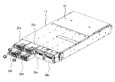
- FIGS. 3 to 6 show the configuration of the uninterruptible power supply 10 in the order of assembly steps.
- FIG. 3 shows a state in the middle of inserting the four power supply units 20 (ad) and the two battery units 30 (a, b) into the shelf 11.
- FIG. 4 shows a state where insertion of each unit into the shelf 11 is completed.
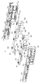
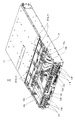
- FIG. 5 is a view showing a state where the upper surface cover 16 at the rear part of the shelf 11 is removed and the connection conductor module 6 is extracted.
- connection conductor module 6 is mounted in the shelf 11 as will be described later.
- the connection conductor module 6 includes a module case 61 formed of an insulating material and a connection conductor portion having conductivity.
- the connection conductor portion includes connection terminals 62 (P, N), connection terminals 63 (P, N), lead terminals 64P, 65N, and connection conductors 64, 65.
- connection terminals 62 (P, N) for connecting to the output terminals of the respective power supply units 20 and connection terminals 63 (P for connecting to the output terminals of the battery unit 30).
- connection terminals 64P and 65N for outputting electric power to the outside are provided.
- connection terminal 62P and the connection terminal 63P are connection terminals on the positive potential side and are connected to the positive electrode connection conductor 64.
- connection terminal 62N and the connection terminal 63N are connection terminals on the negative potential side, and are connected to the negative electrode connection conductor 65.
- An output terminal is provided on the back of the power supply unit 20 and the battery unit 30. Each output terminal is fitted to the connection terminal 62 (P, N) and the connection terminal 63 (P, N) of the connection conductor module 6.
- the output power of the power supply unit 20 and the battery unit 30 is taken out from the lead terminals 64P, 64N and 65P, 65N.
- FIG. 6 is an enlarged view of a portion where the shelf 11 and the connection conductor module 6 are inserted.
- the connection conductor module 6 is fixed to the shelf 11 without using screws. That is, the shelf 11 is provided with fitting grooves 11m on both side walls and a plurality of fitting protrusions 11n on the bottom wall. Further, the connecting conductor module 6 is provided with fitting pieces 61m that fit into the fitting grooves 11m on both side walls, and a fitting hole 61n (not shown) that fits with the fitting protrusion 11n on the bottom wall portion. .
- connection conductor module 6 When the connecting conductor module 6 is inserted into the shelf 11, the fitting piece 61 m of the connecting conductor module 6 is fitted into the fitting groove 11 m of the shelf 11, and the fitting hole 61 n of the connecting conductor module 6 is fitted into the shelf 11. It fits into the protrusion 11n. Thereby, the connection conductor module 6 inserted in the shelf 11 is firmly fixed to the shelf 11 without using a screw. Then, an upper cover 16 is put on the upper opening of the shelf 11 in which the connection conductor module 6 is inserted. Since the top cover 16 is fixed to the shelf 11 with screws, the connection conductor module 6 does not come out of the shelf 11.
- connection conductor portion in the connection conductor module 6 and the shelf 11 can be improved by fixing the connection conductor module 6 to the shelf 11 without using screws.
- insulation performance between the positive potential conductor portion and the negative potential conductor portion in the connection conductor module 6 can be enhanced.
- connection conductor module 6 Next, the assembly process of the connection conductor module 6 will be described with reference to FIGS.
- FIG. 7 shows a state in which all components of the connection conductor module 6 are disassembled.
- the connection conductor module 6 includes a module case 61 made of an insulating material such as an insulating resin and a connection conductor portion having conductivity.
- the module case 61 is divided into a front case 61a and a rear case 61b.
- the front case 61a and the rear case 61b have front and rear surfaces that are open, form a rectangular cylindrical body, and include a plurality of terminal chambers that are partitioned by a partition wall.
- a part of the rear case 61b is inserted into the front case 61a, and both cases are fitted and joined together.
- the front case 61a and the rear case 61b are fixed without using screws.
- the front case 61a includes a plurality of elastic coupling pieces 61c provided with fitting holes 61d at the top end portion of the upper surface.
- the rear case 61b has a plurality of fitting protrusions 61e on the upper surface corresponding to the fitting holes 61d.
- the positive connection conductor 64 and the negative connection conductor 65 held by the module case 61 are bar-shaped conductors made of a copper flat plate or the like.
- a pair of lead terminals 64P and 65N for taking out DC power to the outside are integrally formed at both ends in the width direction of the connection conductors 64 and 65 or in the vicinity of both ends. Thereby, DC power can be taken out from either the left or right side of the uninterruptible power supply 10.
- connection terminals 62P and 63P are fastened and fixed to the positive connection conductor 64 by fixing screws 64k, respectively (see FIG. 8).
- the connection terminal 62P is a terminal connected to the positive output terminal of the power supply unit 20.
- the connection terminal 63P is a terminal connected to the positive output terminal of the battery unit 30.
- Two connection terminals 62N and 63N are fastened and fixed to the negative electrode connection conductor 65 by fixing screws 65k (see FIG. 8).
- the connection terminal 62 ⁇ / b> N is a terminal connected to the negative output terminal of the power supply unit 20.
- the connection terminal 63N is a terminal connected to the negative output terminal of the battery unit 30.
- connection terminals 62P and 62N are provided with four connection terminal pieces 62h and 62d, respectively, corresponding to the output terminals of the power supply units 20a to 20d arranged in two stages and two rows.
- connection terminals 63P and 63N are provided with two connection terminal pieces 63n and 63f respectively corresponding to the output terminals of the battery units 30a and 30b arranged in two rows.
- the front case 61 a has a plurality of terminal chambers 62 (ad), 63 (a, b) corresponding to the storage chambers 12 (ad), 13 (a, b) formed in the shelf 11. Is formed. In these terminal chambers 62 (a to d) and 63 (a and b), the tips of the connection terminal pieces 62 (d and h) and 63 (f and n) are projected to the front side of the front case 61a.
- the connection terminals 62 (P, N) and 63 (P, N) are accommodated.
- FIG. 8 shows a state in which the connection terminals 62P, 62N, 63P, and 63N are integrally fixed to the connection conductors 64 and 65, respectively. 8 is a perspective view seen from the opposite direction to FIG.
- connection conductors 64, 65 When the connection conductors 64, 65 are inserted into the front case 61a, the side edges of the connection terminals 62P, 62N, 63P, 63N coupled to the connection conductors 64, 65 are provided on the bottom wall portion of the front case 61a.
- the holding grooves 61g and 61h are fitted.
- the connection conductors 64, 65 are connected to the front case 61a. Held in place.
- the rear case 61b is inserted and fitted into the front case 61a.
- the fitting projection 61e of the rear case 61b enters the lower side of the elastic coupling piece 61c while elastically deforming and pushing up the elastic coupling piece 61c on the upper surface of the front case 61a.
- the fitting protrusion 61e of the rear case 61b reaches the position of the fitting hole 61d provided in the elastic coupling piece 61c of the front case 61a, it fits into the fitting hole 61d.
- connection conductors 64 and 65 incorporated in the front case 61 a are suppressed by the rear case 61 b from the rear surface side, and the connection conductors 64 and 65 are fixedly held by the module case 61.
- FIG. 9 shows a state in which the connection conductors 64 and 65 are inserted into the front case 61a.
- the positive electrode connection conductor 64 and the connection terminals 62P and 63P coupled thereto are shown by high density hatching.
- the negative electrode connection conductor 65 and the connection terminals 62N and 63N coupled to the negative electrode connection conductor 65 are indicated by low density hatching.
- the positive connection terminals 62P and 63P and the negative connection terminals 62N and 63N are alternately arranged in the width direction of the module case 61.
- the external appearance of the connecting conductor module 6 is shown in FIG.
- the module case 61 is configured by fitting a part of the rear case 61b into the front case 61a. Therefore, from the appearance, the trace (parting line) obtained by joining the front case 61a and the rear case 61b can hardly be seen, and the module case 61 shows a substantially integrated appearance.
- the appearance of the power supply unit 20 is shown in FIG.
- the power supply unit 20 houses an AC / DC converter 22 and a DC / DC converter 23 in a unit case 24. On the back surface of the power supply unit 20, two sets of a positive output terminal 21P and a negative output terminal 21N for outputting DC power are provided. The reason why two sets of the positive output terminal 21P and the negative output terminal 21N are provided is to reduce the current flowing per terminal and to reduce the contact resistance of the electrical connection portion with the connection conductor module 6.
- the output terminals 21P and 21N are formed as pinched female terminals.
- the connection terminal pieces 62 (d, h) and 63 (f, n) of the connection conductor module 6 connected to the output terminals 21P and 21N are formed as flat male terminals as shown in FIG.
- the output terminals 31P and 31N of the battery unit 30 are also formed as pinched female terminals having the same shape as the output terminals 21P and 21N of the power supply unit 20.
- connection terminal pieces 62 (d, h) of the connection conductor module 6 are inserted into the gaps between the output terminals 21P, 21N of the power supply unit 20 and are sandwiched between the output terminals 21P, 21N.
- electrical connection between the power supply unit 20 and the connection conductor module 6 is performed at the front opening of the module case 61.
- the connection terminal piece 63 (f, n) of the connection conductor module 6 is similarly inserted into the gap between the output terminals 31P and 31N of the battery unit 30 and sandwiched between the output terminals 31P and 31N. Thereby, the electrical connection between the battery unit 30 and the connection conductor module 6 is performed.
- connection conductor module 6 houses the power supply unit 20, the battery unit 30, and the connection conductor module 6 in the shelf 11.
- External output terminals 11P and 11N are provided on the back of the shelf 11 of the uninterruptible power supply 10.
- the external output terminals 11P and 11N are connected to the external lead terminals 64P and 65N of the connection conductor module 6 by the connection line 12.
- the external output terminals 11P and 11N of the uninterruptible power supply 10 are connected to the output terminals of the power supply unit 20 and the battery unit 30 in the shelf 11 via the connection line 12 and the connection conductor module 6.
- a flexible insulated wire as the connection line 12.
- connection line 12 includes two positive side connection lines 12a and 12b and two negative side connection lines 12c and 12d.
- the connection line 12 is configured by connecting the two connection lines in parallel as described above, the electrical resistance is halved, so that the resistance loss of the connection line 12 can be reduced. Thereby, the efficiency of the uninterruptible power supply 10 whole can be improved.
- FIG. 14 is a diagram showing a terminal structure included in the uninterruptible power supply 10 which is an embodiment of the present invention. This figure shows an embodiment of a terminal structure for connecting two connection lines 12a and 12b in parallel to the lead terminal 64P of the connection conductor module 6.
- connection terminals 13a and 13b formed in a square shape are connected to one end of the connection lines 12a and 12b.
- the two connection terminals 13a and 13b are arranged side by side on a lead terminal 64P formed in a square shape.
- the presser plate 14 formed in a square shape having substantially the same size as the lead terminal 64P is disposed on the connection terminals 13a and 13b.
- the lead terminal 64P sandwiching the connection terminals 13a and 13b and the presser plate 14 are fastened with equal pressure by the fastening bolts 15a and 15b. Thereby, the connection terminals 13a and 13b are fixed to the lead terminal 64P with equal pressure.
- the presser plate 14 is formed of a rectangular iron plate having high mechanical rigidity and high thermal conductivity, and has a surface plated with tin. With such a configuration, the entire contact surfaces of the two connection terminals 13a and 13b can be brought into contact with the lead terminal 64P with substantially equal pressure. For this reason, the contact resistance of the contact portion between the two connection terminals 13a and 13b and the lead terminal 64P can be reduced. As a result, it is possible to suppress the bias of the current flowing through the two connection terminals 13a and 13b and to reduce the loss caused by the contact resistance of the terminal portion.
- connection terminals 13c and 13d are connected to one ends of the connection lines 12c and 12d.
- the lead terminal 65N sandwiching the connection terminals 13c and 13d and the presser plate 14 are fastened with equal pressure by the fastening bolts 15a and 15b. Accordingly, the connection terminals 13c and 13d are fixed to the lead terminal 65N with an equal pressure. Therefore, the entire contact surfaces of the two connection terminals 13c and 13d can be brought into contact with the lead terminal 65N with substantially equal pressure. For this reason, the contact resistance of the contact portion between the two connection terminals 13c and 13d and the lead terminal 64P can be reduced. As a result, it is possible to suppress the bias of the current flowing through the two connection terminals 13c and 13d and to reduce the loss caused by the contact resistance of the terminal portion.
- the presser plate 14 may be made of a material other than the iron plate, such as stainless steel, as long as it has high mechanical rigidity and high thermal conductivity. Further, the presser plate 14 has a rising piece 14a formed by bending a part of the outer side at a right angle and rising several mm. The rising piece 14a functions to increase the rigidity of the presser plate 14 and to increase the heat dissipation effect by expanding the surface area. Thereby, the heat dissipation effect of the terminal connection part is improved, and the temperature rise of this part can be suppressed.
- the uninterruptible power supply 10 described here is configured by storing a power supply unit 20, a battery unit 30, and a connection conductor module 6 in a shelf 11, as in the uninterruptible power supply 10 described above.
- a power supply unit 20 a battery unit 30, and a connection conductor module 6 in a shelf 11, as in the uninterruptible power supply 10 described above.
- work for extracting a part of the power supply units 20 or the battery units 30 from the shelf 11 of the uninterruptible power supply 10 occurs. As shown in FIG.
- the cross-sectional area of the storage chamber 13 that stores the battery unit 30 is larger than the cross-sectional area of the storage chamber 12 that stores the power supply unit 20. Therefore, it is easy to insert a hand or a tool into the storage chamber 13 from which the battery unit 30 has been extracted. Moreover, since the cross-sectional area of the storage chamber 12 in which the power supply unit 20 is stored is small, it is not easy to insert a hand here. However, a thin rod-like tool such as a screwdriver can be inserted relatively easily.
- connection terminals 62 ⁇ / b> P, 62 ⁇ / b> N, 63 ⁇ / b> P, and 63 ⁇ / b> N of the connection conductor module 6 are exposed at the back of the storage chambers 12 and 13.
- the connection terminals 62P, 62N, 63P, and 63N of the connection conductor module 6 exposed the hands are brought into contact with these terminals. Risk of electric shock.
- connection terminals 62P, 62N, 63P, and 63N When a tool or the like is inserted into the storage chambers 12 and 13 from which the power supply unit 20 or the battery unit 30 has been removed, it comes into contact with the connection terminals 62P, 62N, 63P, and 63N, and a DC power supply short circuit accident occurs. There is danger.
- the uninterruptible power supply 10 shown in FIG. 15A uses a flapper mechanism 17 at a position between the insertion port of the storage chamber 13 and the front surface of the connection conductor module 6.
- a storage room shielding mechanism is provided.
- the flapper mechanism 17 includes a flapper 17a and a latch plate 18.
- the flapper 17 a has a flat plate shape and has a pair of support protrusions 17 b and 17 b that are formed to protrude outward at both upper ends thereof.
- the support protrusions 17 b and 17 b are inserted into bearing holes 13 a provided in the upper portions of both side walls of the storage chamber 13, so that the flapper 17 a is rotatably supported in the storage chamber 13.
- the flapper 17 a hangs vertically due to gravity and closes the front surface of the connection conductor module 6.
- the uninterruptible power supply 10 is provided with a latch plate 18 for preventing the flapper 17a from being rotated at this position even if a hand or the like is inserted into the storage chamber 13.
- the flapper mechanism 71 can prevent a human hand or the like inserted into the storage chamber 13 from touching the connection terminals 62P, 62N, 63P, 63N of the connection conductor module 6.
- FIG. 17 shows a detailed configuration of the flapper mechanism 17, (a) is a plan sectional view showing the flapper mechanism 17 in an enlarged manner, and (b) is a further enlarged view by partially cutting out the part. It is a perspective view shown.
- the flapper 17a hangs vertically and closes the front surface of the connection conductor module 6. At this time, the flapper 17a is latched by the latch plate 18 so as not to be pushed open by an external force.
- the latch plate 18 is made of a spring material, has a hook-shaped latch piece 18 a at the tip, and is disposed outside the storage chamber 13.
- the latch plate 18 is fixed to the outer wall of the storage chamber 13, that is, the outer wall of the shelf 11, at the base end opposite to the tip provided with the latch piece 18 a.
- the latch plate 18 includes a latch piece 18a at the tip, and two pressing protrusions 18b and 18c that protrude toward the storage chamber 13 at an intermediate portion.
- the latch plate 18 is pressed against the outer wall of the storage chamber 13 by its own spring force. For this reason, the latch piece 18 a provided at the tip and the pressing projections 18 b and 18 c provided at the intermediate portion enter the storage chamber 13 through the through holes provided in the outer wall of the storage chamber 13.
- the latch piece 18a that has entered the storage chamber 13 presses the back surface of the vertical flapper 17a, and locks the flapper 17a from the back surface side. For this reason, even if the pushing force P as shown by the arrow is applied to the front surface side of the flapper 17a, the rotation of the flapper 17a is prevented.
- FIG. 15B is a diagram in the middle of inserting the battery unit 30 into the storage chamber 13. This figure shows that the protrusion 31r provided on the upper part of the battery unit 30 has just reached the installation position of the flapper 17a.
- the pressing body 31 s provided on the side wall of the battery unit 30 comes into contact with the pressing protrusion 18 c of the latch plate 18 that has entered the storage chamber 13.
- the pressing projection 18 c comes into contact with the pressing projection 18 c
- the latch plate 18 is elastically deformed, and the pressing projection 18 c and the latch piece 18 a are pushed out of the storage chamber 13.
- the latch piece 18a is pushed out of the storage chamber 13, the locking of the flapper 17a is released, so that the flapper 17a can be rotated.
- the flapper 17a When the battery unit 30 is further pushed in, the flapper 17a is pushed by the protrusion 31r and rotates upward. The rotated flapper 17a is in a horizontal state at the top of the storage chamber 13 as shown in FIGS. 18 (a) and 18 (b). As a result, the interior of the storage chamber 13 is completely opened.
- the output terminals 31P, 31N of the battery unit 30 are joined to the connection terminal pieces 62P, 62N, 63P, 63N of the connection conductor module 6 and are electrically connected.
- the protrusion 31r at the tip of the battery unit 30 is detached from the flapper 17a. Then, the flapper 17a is not supported from below, rotates downward by its own weight, and hangs vertically. With the removal of the battery unit 30, the pressing of the latch plate 18 by the pressing body 31s of the battery unit 30 is also released. Then, the latch plate 18 returns to a position where it comes into contact with the outer wall of the shelf 11 by its own spring force. As a result, the latch piece 18 a enters the storage chamber 13 of the shelf 11. The latch piece 18a that has entered the storage chamber 13 of the shelf 11 locks the lower end of the flapper 17a to prevent the flapper 17a from rotating. In this way, the battery unit 30 can be inserted, and it is possible to reliably prevent human hands or tools inserted from the insertion port of the storage chamber 13 from coming into contact with the connection terminals of the connection conductor module 6.
- the storage chamber 12 for storing the power supply unit 20 has a small cross-sectional area, but a rod-like tool such as a screwdriver can be inserted. Therefore, in order to prevent such a contact accident due to a tool, a storage chamber shielding mechanism using a flapper mechanism 17 similar to the storage chamber 13 of the battery unit 30 may be provided in the storage chamber 12 in which the power supply unit 20 is stored. it can.
- Uninterruptible power supply 11 Shelf 12 (a, b, c, d): Connection line 13 (a, b, c, d): Connection terminal 14: Presser plate 14a: Launch piece 15 (a, b) : Fastening bolt 16: Top cover 20 (a, b, c, d): Power supply unit 30 (a, b): Battery unit 40: Server rack 4 (a to n): Server unit 6: Connection conductor module 61: Module Case 62 (P, N), 63 (P, N): Connection terminal 64P, 65N: Lead-out terminal
Abstract
L'invention fournit un système d'alimentation dans lequel des unités conversion de puissance admises sur un support de serveur, sont connectées entre elles à l'intérieur d'une tablette dans laquelle elles sont admises, et qui présente une connexion facile à un jeu de barres à l'intérieur du support de serveur. Une unité alimentation convertissant une puissance électrique de courant alternatif en puissance électrique de courant continu, et une unité batterie convertissant une puissance électrique dont est chargée une batterie en puissance électrique de courant continu et l'émettant en sortie, sont admises ensemble sur une tablette, et un dispositif d'alimentation sans interruption de service est ainsi configuré. Une borne sortie de courant continu de l'unité alimentation et une borne sortie de courant continu de l'unité batterie, sont connectées en parallèle, à l'intérieur de ladite tablette, par un module de conducteurs de connexion maintenant des conducteurs de connexion dans une partie interne. Ce module de conducteurs de connexion est configuré par une enveloppe de module formée par un matériau isolant, et par les conducteurs de connexion admis à l'intérieur de cette enveloppe de module.
Priority Applications (3)
| Application Number | Priority Date | Filing Date | Title |
|---|---|---|---|
| CN201680004906.8A CN107111348A (zh) | 2015-07-03 | 2016-03-10 | 电源装置以及具备该电源装置的服务器系统 |
| JP2017527088A JP6787316B2 (ja) | 2015-07-03 | 2016-03-10 | 電源装置およびこの電源装置を備えるサーバシステム |
| US15/641,555 US20170300100A1 (en) | 2015-07-03 | 2017-07-05 | Power supply device and server system provided with same |
Applications Claiming Priority (4)
| Application Number | Priority Date | Filing Date | Title |
|---|---|---|---|
| JP2015-134645 | 2015-07-03 | ||
| JP2015134645 | 2015-07-03 | ||
| JP2015-135037 | 2015-07-06 | ||
| JP2015135037 | 2015-07-06 |
Related Child Applications (1)
| Application Number | Title | Priority Date | Filing Date |
|---|---|---|---|
| US15/641,555 Continuation US20170300100A1 (en) | 2015-07-03 | 2017-07-05 | Power supply device and server system provided with same |
Publications (1)
| Publication Number | Publication Date |
|---|---|
| WO2017006586A1 true WO2017006586A1 (fr) | 2017-01-12 |
Family
ID=57685017
Family Applications (3)
| Application Number | Title | Priority Date | Filing Date |
|---|---|---|---|
| PCT/JP2016/057518 WO2017006588A1 (fr) | 2015-07-03 | 2016-03-10 | Dispositif d'alimentation |
| PCT/JP2016/057517 WO2017006587A1 (fr) | 2015-07-03 | 2016-03-10 | Structure de connexion de borne et système d'alimentation pour serveur équipé de cette structure |
| PCT/JP2016/057516 WO2017006586A1 (fr) | 2015-07-03 | 2016-03-10 | Dispositif d'alimentation, et système de serveur équipé de celui-ci |
Family Applications Before (2)
| Application Number | Title | Priority Date | Filing Date |
|---|---|---|---|
| PCT/JP2016/057518 WO2017006588A1 (fr) | 2015-07-03 | 2016-03-10 | Dispositif d'alimentation |
| PCT/JP2016/057517 WO2017006587A1 (fr) | 2015-07-03 | 2016-03-10 | Structure de connexion de borne et système d'alimentation pour serveur équipé de cette structure |
Country Status (5)
| Country | Link |
|---|---|
| US (1) | US20170300100A1 (fr) |
| JP (3) | JPWO2017006588A1 (fr) |
| CN (1) | CN107111348A (fr) |
| TW (3) | TW201702796A (fr) |
| WO (3) | WO2017006588A1 (fr) |
Cited By (2)
| Publication number | Priority date | Publication date | Assignee | Title |
|---|---|---|---|---|
| EP3461246A3 (fr) * | 2017-09-01 | 2019-07-03 | Delta Electronics, Inc. | Étagère de distribution d'énergie d'entrées multiples et son ensemble de barre de bus |
| US10404041B2 (en) | 2017-09-01 | 2019-09-03 | Delta Electronics, Inc. | Multiple input power distribution shelf and bus bar assembly thereof |
Families Citing this family (4)
| Publication number | Priority date | Publication date | Assignee | Title |
|---|---|---|---|---|
| JP6407452B2 (ja) * | 2015-11-30 | 2018-10-17 | 三菱電機株式会社 | 直流分電盤およびマイグレーション装置 |
| US10470333B2 (en) * | 2018-01-05 | 2019-11-05 | Quanta Computer Inc. | Flexible chassis for different sized sleds |
| TWI737477B (zh) * | 2020-09-01 | 2021-08-21 | 新加坡商鴻運科股份有限公司 | 散熱主機殼及具有該散熱主機殼之散熱裝置 |
| US11382237B1 (en) * | 2020-12-29 | 2022-07-05 | Quanta Computer Inc. | Chassis power supply reception |
Citations (2)
| Publication number | Priority date | Publication date | Assignee | Title |
|---|---|---|---|---|
| US20070114852A1 (en) * | 2005-11-18 | 2007-05-24 | Delta Electronics, Inc. | Parallel uninterruptible power supply system |
| JP2011125124A (ja) * | 2009-12-09 | 2011-06-23 | Sanyo Electric Co Ltd | サーバーとサーバーに収納される無停電電源装置 |
Family Cites Families (25)
| Publication number | Priority date | Publication date | Assignee | Title |
|---|---|---|---|---|
| JPH05335041A (ja) * | 1992-05-29 | 1993-12-17 | Fujitsu Ltd | 端子接続方法 |
| JPH07200101A (ja) * | 1993-12-28 | 1995-08-04 | Fujitsu Ltd | 電源ユニット |
| JPH0935774A (ja) * | 1995-07-20 | 1997-02-07 | Sony Corp | 環状導電端子の固定装置 |
| JP3120704B2 (ja) * | 1995-08-07 | 2000-12-25 | 住友電装株式会社 | ボルト止め圧着端子 |
| JPH11111353A (ja) * | 1997-10-03 | 1999-04-23 | Nemic Lambda Kk | 端子台 |
| JPH11110083A (ja) * | 1997-10-07 | 1999-04-23 | Hitachi Ltd | 情報処理装置 |
| JP3037289B1 (ja) * | 1998-11-12 | 2000-04-24 | 甲府日本電気株式会社 | 電源冗長機能を有する装置 |
| US6650537B2 (en) * | 2001-10-31 | 2003-11-18 | Hewlett-Packard Development Company, L.P. | Low profile DC distribution module for a power supply unit |
| US7173821B2 (en) * | 2003-05-16 | 2007-02-06 | Rackable Systems, Inc. | Computer rack with power distribution system |
| JP4181028B2 (ja) * | 2003-12-22 | 2008-11-12 | 矢崎総業株式会社 | 電気接続箱 |
| US7137850B2 (en) * | 2004-11-01 | 2006-11-21 | Ewing Carrel W | Circuit link connector |
| US7252524B1 (en) * | 2006-03-17 | 2007-08-07 | Eaton Power Quality Corporation | Power interconnect assemblies and methods for configuring the same |
| NO324673B1 (no) * | 2006-05-08 | 2007-12-03 | Eltek Valere As | Switch mode kraftforsyningssystem |
| JP4434181B2 (ja) * | 2006-07-21 | 2010-03-17 | 株式会社日立製作所 | 電力変換装置 |
| JP2009170128A (ja) * | 2008-01-11 | 2009-07-30 | Chugoku Electric Power Co Inc:The | ボルト等緩み止め金具 |
| JP2010087028A (ja) * | 2008-09-29 | 2010-04-15 | Shindengen Electric Mfg Co Ltd | 電子機器装置 |
| JP5505117B2 (ja) * | 2010-06-16 | 2014-05-28 | 横河電機株式会社 | 絶縁電源装置 |
| JP5803130B2 (ja) * | 2011-02-16 | 2015-11-04 | 富士通株式会社 | 電子機器 |
| JP2012248140A (ja) * | 2011-05-31 | 2012-12-13 | Shinohara Electric Co Ltd | サーバシステムにおける直流電源の給電構造 |
| JP2013065684A (ja) * | 2011-09-16 | 2013-04-11 | Toshiba Mitsubishi-Electric Industrial System Corp | 電気機器収容装置 |
| JP5845941B2 (ja) * | 2012-02-02 | 2016-01-20 | 富士通株式会社 | 蓋開閉装置及び収納装置 |
| CN102611309A (zh) * | 2012-02-24 | 2012-07-25 | 山东齐林电科电力设备制造有限公司 | 高绝缘耐压隔离电源 |
| CN104620469B (zh) * | 2013-03-15 | 2018-03-30 | 富士电机株式会社 | 不间断电源装置 |
| JP2014203814A (ja) * | 2013-04-10 | 2014-10-27 | 株式会社ミスミ | 端子接続構造とこれを備える端子台、及び端子接続方法 |
| CN104426387B (zh) * | 2013-09-06 | 2019-04-19 | 力博特公司 | 用于机架可安装模块化直流电力单元的系统以及方法 |
-
2016
- 2016-03-10 WO PCT/JP2016/057518 patent/WO2017006588A1/fr active Application Filing
- 2016-03-10 JP JP2017527090A patent/JPWO2017006588A1/ja not_active Withdrawn
- 2016-03-10 JP JP2017527089A patent/JP6753399B2/ja active Active
- 2016-03-10 JP JP2017527088A patent/JP6787316B2/ja active Active
- 2016-03-10 CN CN201680004906.8A patent/CN107111348A/zh active Pending
- 2016-03-10 WO PCT/JP2016/057517 patent/WO2017006587A1/fr active Application Filing
- 2016-03-10 WO PCT/JP2016/057516 patent/WO2017006586A1/fr active Application Filing
- 2016-06-13 TW TW105118415A patent/TW201702796A/zh unknown
- 2016-06-13 TW TW105118417A patent/TW201716915A/zh unknown
- 2016-06-13 TW TW105118416A patent/TW201711284A/zh unknown
-
2017
- 2017-07-05 US US15/641,555 patent/US20170300100A1/en not_active Abandoned
Patent Citations (2)
| Publication number | Priority date | Publication date | Assignee | Title |
|---|---|---|---|---|
| US20070114852A1 (en) * | 2005-11-18 | 2007-05-24 | Delta Electronics, Inc. | Parallel uninterruptible power supply system |
| JP2011125124A (ja) * | 2009-12-09 | 2011-06-23 | Sanyo Electric Co Ltd | サーバーとサーバーに収納される無停電電源装置 |
Cited By (4)
| Publication number | Priority date | Publication date | Assignee | Title |
|---|---|---|---|---|
| EP3461246A3 (fr) * | 2017-09-01 | 2019-07-03 | Delta Electronics, Inc. | Étagère de distribution d'énergie d'entrées multiples et son ensemble de barre de bus |
| US10404041B2 (en) | 2017-09-01 | 2019-09-03 | Delta Electronics, Inc. | Multiple input power distribution shelf and bus bar assembly thereof |
| US10951013B2 (en) | 2017-09-01 | 2021-03-16 | Delta Electronics, Inc. | Multiple input power distribution shelf and bus bar assembly thereof |
| EP4044778A1 (fr) * | 2017-09-01 | 2022-08-17 | Delta Electronics, Inc. | Étagère de distribution d'énergie d'entrées multiples et son ensemble de barre de bus |
Also Published As
| Publication number | Publication date |
|---|---|
| TW201702796A (zh) | 2017-01-16 |
| JPWO2017006586A1 (ja) | 2018-04-19 |
| JP6787316B2 (ja) | 2020-11-18 |
| WO2017006587A1 (fr) | 2017-01-12 |
| CN107111348A (zh) | 2017-08-29 |
| TW201711284A (zh) | 2017-03-16 |
| TW201716915A (zh) | 2017-05-16 |
| JP6753399B2 (ja) | 2020-09-09 |
| JPWO2017006587A1 (ja) | 2018-04-19 |
| JPWO2017006588A1 (ja) | 2018-04-19 |
| US20170300100A1 (en) | 2017-10-19 |
| WO2017006588A1 (fr) | 2017-01-12 |
Similar Documents
| Publication | Publication Date | Title |
|---|---|---|
| WO2017006586A1 (fr) | Dispositif d'alimentation, et système de serveur équipé de celui-ci | |
| US9986658B2 (en) | Power connection clip for a shelf in a server rack | |
| CN110352633B (zh) | 逆变器装置 | |
| JP5678240B2 (ja) | ヒューズを備える合成/分配バスバーアセンブリを有するターミナルユニット | |
| US20180198247A1 (en) | Modular Assembly Housing | |
| KR20110057590A (ko) | 대용량 배터리 팩과 대용량 배터리 팩의 조립체 | |
| KR101468144B1 (ko) | 인버터 모듈 | |
| EP2858229B1 (fr) | Appareil permettant de connecter une liaison de bus CC partagée | |
| US9673602B2 (en) | System for isolating power conductors using cover assemblies | |
| US20020004328A1 (en) | Multiple pin contactor device for power bus bar systems | |
| US20180190964A1 (en) | Electrical energy storage module | |
| CN204858285U (zh) | 一种无孔封闭母线系统及断路器转接器组件 | |
| CN210805861U (zh) | 电池箱装置及电池箱系统 | |
| JP6362549B2 (ja) | 蓄電装置 | |
| CN108539693B (zh) | 母线组合式铜排固定安装结构 | |
| CN112670630A (zh) | 电池箱装置及电池箱系统 | |
| CN111602305B (zh) | 用于电气柜的导电母线 | |
| EP3375059B1 (fr) | Support de distribution modulaire pour disjoncteurs | |
| CN216871825U (zh) | 一种隔离开关 | |
| KR101427209B1 (ko) | 인버터 모듈의 접속 구조 | |
| JP6452402B2 (ja) | 蓄電装置 | |
| CN210007171U (zh) | 电源机柜和电源系统 | |
| WO2023015790A1 (fr) | Armoire de commande de type tiroir, disjoncteur à boîtier moulé, ensembles enfichables et appareil | |
| CN218887942U (zh) | 一种可抽出式配电模块 | |
| CN215601578U (zh) | 一种储能模块及储能机柜 |
Legal Events
| Date | Code | Title | Description |
|---|---|---|---|
| 121 | Ep: the epo has been informed by wipo that ep was designated in this application |
Ref document number: 16821057 Country of ref document: EP Kind code of ref document: A1 |
|
| ENP | Entry into the national phase |
Ref document number: 2017527088 Country of ref document: JP Kind code of ref document: A |
|
| NENP | Non-entry into the national phase |
Ref country code: DE |
|
| 122 | Ep: pct application non-entry in european phase |
Ref document number: 16821057 Country of ref document: EP Kind code of ref document: A1 |