WO2017006586A1 - Power supply device and server system provided with same - Google Patents
Power supply device and server system provided with same Download PDFInfo
- Publication number
- WO2017006586A1 WO2017006586A1 PCT/JP2016/057516 JP2016057516W WO2017006586A1 WO 2017006586 A1 WO2017006586 A1 WO 2017006586A1 JP 2016057516 W JP2016057516 W JP 2016057516W WO 2017006586 A1 WO2017006586 A1 WO 2017006586A1
- Authority
- WO
- WIPO (PCT)
- Prior art keywords
- power supply
- power
- connection conductor
- supply device
- connection
- Prior art date
Links
- 239000004020 conductor Substances 0.000 claims abstract description 117
- 238000006243 chemical reaction Methods 0.000 claims abstract description 22
- 239000011810 insulating material Substances 0.000 claims abstract description 6
- 238000003860 storage Methods 0.000 description 56
- 238000003825 pressing Methods 0.000 description 9
- 238000010586 diagram Methods 0.000 description 8
- 238000009826 distribution Methods 0.000 description 5
- XEEYBQQBJWHFJM-UHFFFAOYSA-N Iron Chemical compound [Fe] XEEYBQQBJWHFJM-UHFFFAOYSA-N 0.000 description 4
- 230000008878 coupling Effects 0.000 description 4
- 238000010168 coupling process Methods 0.000 description 4
- 238000005859 coupling reaction Methods 0.000 description 4
- 238000003780 insertion Methods 0.000 description 4
- 230000037431 insertion Effects 0.000 description 4
- 230000002457 bidirectional effect Effects 0.000 description 3
- 238000009434 installation Methods 0.000 description 3
- 230000000630 rising effect Effects 0.000 description 3
- 238000005520 cutting process Methods 0.000 description 2
- 230000000694 effects Effects 0.000 description 2
- 230000012447 hatching Effects 0.000 description 2
- 230000017525 heat dissipation Effects 0.000 description 2
- 238000009413 insulation Methods 0.000 description 2
- 229910052742 iron Inorganic materials 0.000 description 2
- 239000000463 material Substances 0.000 description 2
- 238000000034 method Methods 0.000 description 2
- RYGMFSIKBFXOCR-UHFFFAOYSA-N Copper Chemical compound [Cu] RYGMFSIKBFXOCR-UHFFFAOYSA-N 0.000 description 1
- ATJFFYVFTNAWJD-UHFFFAOYSA-N Tin Chemical compound [Sn] ATJFFYVFTNAWJD-UHFFFAOYSA-N 0.000 description 1
- 238000005452 bending Methods 0.000 description 1
- 229910052802 copper Inorganic materials 0.000 description 1
- 239000010949 copper Substances 0.000 description 1
- 230000007423 decrease Effects 0.000 description 1
- 238000000605 extraction Methods 0.000 description 1
- 230000005484 gravity Effects 0.000 description 1
- 230000020169 heat generation Effects 0.000 description 1
- 238000007689 inspection Methods 0.000 description 1
- 238000005304 joining Methods 0.000 description 1
- 238000012423 maintenance Methods 0.000 description 1
- 239000002184 metal Substances 0.000 description 1
- 229910052751 metal Inorganic materials 0.000 description 1
- 238000005192 partition Methods 0.000 description 1
- 239000011347 resin Substances 0.000 description 1
- 229920005989 resin Polymers 0.000 description 1
- 229910001220 stainless steel Inorganic materials 0.000 description 1
- 239000010935 stainless steel Substances 0.000 description 1
Images


Classifications
-
- G—PHYSICS
- G06—COMPUTING; CALCULATING OR COUNTING
- G06F—ELECTRIC DIGITAL DATA PROCESSING
- G06F1/00—Details not covered by groups G06F3/00 - G06F13/00 and G06F21/00
- G06F1/26—Power supply means, e.g. regulation thereof
- G06F1/266—Arrangements to supply power to external peripherals either directly from the computer or under computer control, e.g. supply of power through the communication port, computer controlled power-strips
-
- H—ELECTRICITY
- H05—ELECTRIC TECHNIQUES NOT OTHERWISE PROVIDED FOR
- H05K—PRINTED CIRCUITS; CASINGS OR CONSTRUCTIONAL DETAILS OF ELECTRIC APPARATUS; MANUFACTURE OF ASSEMBLAGES OF ELECTRICAL COMPONENTS
- H05K7/00—Constructional details common to different types of electric apparatus
- H05K7/14—Mounting supporting structure in casing or on frame or rack
- H05K7/1485—Servers; Data center rooms, e.g. 19-inch computer racks
- H05K7/1488—Cabinets therefor, e.g. chassis or racks or mechanical interfaces between blades and support structures
- H05K7/1492—Cabinets therefor, e.g. chassis or racks or mechanical interfaces between blades and support structures having electrical distribution arrangements, e.g. power supply or data communications
-
- G—PHYSICS
- G06—COMPUTING; CALCULATING OR COUNTING
- G06F—ELECTRIC DIGITAL DATA PROCESSING
- G06F1/00—Details not covered by groups G06F3/00 - G06F13/00 and G06F21/00
- G06F1/16—Constructional details or arrangements
- G06F1/18—Packaging or power distribution
- G06F1/189—Power distribution
Definitions
- the present invention relates to, for example, a power supply device that supplies DC power to a server system installed in a data center, and a server system including the power supply device.
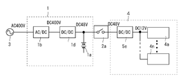
- FIG. 19 shows a schematic configuration of a conventional general server system power supply system disclosed in Patent Document 1.
- This power supply system includes an uninterruptible power supply 1 connected to an AC 400V system power supply 3 and a transformer 2 that insulates and converts the voltage of the AC power output from the uninterruptible power supply 1.
- the uninterruptible power supply 1 includes a battery 1a, an AC / DC converter 1b, and a DC / AC converter 1c.
- the battery 1a is charged by an AC / DC converter 1b that converts AC power from the system power supply 3 into DC power.
- the DC power output from the AC / DC converter 1b or the DC power discharged from the battery 1a is converted into AC power of 400V AC by the DC / AC converter 1c.
- the 400V AC power output from the DC / AC converter 1c is converted by the transformer 2 into 200V or 100V AC power. Further, the converted AC power is converted into low voltage (12 V) DC power by the power converter 5 in the server system 4.
- the power converter 5 is composed of a series circuit of an AC / DC converter 5a and a DC / DC converter 5b. This 12V DC power is supplied to a plurality of servers 4a to 4n serving as loads. The individual servers 4a to 4n in the server system operate with 12V DC power.
- a plurality of servers 4a to 4n are stored in a server rack by a predetermined number to constitute a server system.
- the power converter 5 is provided corresponding to each server system. And the power converter 5 is integrally accommodated in the server rack in which each server is accommodated.
- the power supply system shown in FIG. 20 supplies high-voltage (400 V) DC power output from the AC / DC converter 1b of the uninterruptible power supply 1 to the server system 4 via the DC distribution device 2a.
- the high voltage (400V) direct current power is converted into a low voltage direct current power of 12V by the DC / DC converter 5d in the server system 4.
- This power supply system is referred to as a high voltage direct current power supply system (HVDC).
- the uninterruptible power supply 1 further includes a DC / DC converter 1d.
- the high voltage (400V) DC power output from the AC / DC converter 1b is converted into low voltage (48V) DC power by the DC / DC converter 1d.
- This low voltage (48V) DC power is supplied to the server system 4 via the DC power distribution equipment 2a.
- the low voltage (48V) DC power is further converted into low voltage (12V) DC power by the DC / DC converter 5e in the server system 4.
- This power supply system is referred to as a low voltage DC power supply system.
- the power conversion efficiency can be increased.
- a circuit breaker for cutting off high-voltage DC power is required as the DC power distribution circuit breaker 2a.
- the circuit breaker capable of interrupting high-voltage DC power is not only large, but also requires electric shock countermeasures for DC high-voltage (DC400V) distribution.
- Patent Document 1 proposes a power supply system shown in FIG.
- the power supply system shown in FIG. 22 supplies 200 V AC power supplied from the AC system power supply 3 to the server system 4.
- the server rack 40 of the server system 4 houses the uninterruptible power supply 10 and a plurality of servers 4a to 4n.
- the uninterruptible power supply 10 includes a power supply unit 20 and a battery unit 30.
- the power supply circuit unit 21 of the power supply unit 20 includes an AC / DC converter 22 that converts AC power supplied from the system power supply 3 into DC power, and DC power output from the AC / DC converter 22 to 12V DC power.
- a DC / DC converter 23 for conversion is provided. 12V DC power output from the DC / DC converter 23 is supplied to the servers 4a to 4n.
- the battery circuit unit 31 of the battery unit 30 includes a battery 32 that charges DC power and a DC / DC converter 33 that allows DC current to flow in both directions.
- the battery 32 is connected in parallel to the output of the power supply circuit unit 21 via a bidirectional DC / DC converter 33.
- the battery 32 is charged by the direct current output of the power supply circuit unit 21 through the bidirectional DC / DC converter 33 and supplies the charged direct current power to the servers 4a to 4n via the DC / DC converter 33.
- the power supply unit 20 and the battery unit 30 configured in this way are housed in a common shelf 50 as shown in FIGS. 23A and 23B to form the uninterruptible power supply 10. Yes.
- Output terminals drawn out to the back sides of the power supply unit 20 and the battery unit 30 are connected to power buses 42 and 43 in the server rack 40 via connectors 44.
- the power buses 42 and 43 are connected to a power input terminal of a server (load) 4 (not shown).
- Storing the power supply unit and the battery unit together with the server in the server rack in this way can reduce the installation space as compared with the case where the uninterruptible power supply is installed separately. Further, when the uninterruptible power supply fails, the influence is limited to only the server stored in the server rack, and does not affect the servers in other server racks. Therefore, the reliability of the server system can be improved.
- the present invention provides a power supply device that supplies DC power, the power supply device including a plurality of power conversion units that output the DC power, and output terminals of the plurality of power conversion units.
- a connection conductor module for parallel connection, a plurality of power conversion units, and a shelf for storing the connection conductor module are provided, and the connection conductor module is stored in a module case formed of an insulating material and the module case It is characterized by comprising a connecting conductor.
- the module case has an opening in a surface facing the plurality of power conversion units
- the connection conductor includes a terminal for fitting with an output terminal of the plurality of power conversion units.
- the terminal of the connection conductor is fitted and coupled to the output terminals of the plurality of power conversion units at the opening.
- the module case is composed of a first case and a second case, and the connection conductor is formed by fitting the first case and the second case into the module case. It is fixed and held inside.
- connection conductor is mounted and fixed in a holding groove provided in the first case or the second case.
- connection conductor module includes a fitting portion for fitting with a fitting portion provided on at least one of the side wall and the bottom wall of the shelf.
- connection conductor and the shelf are insulated by the module case on the upper surface, the bottom surface, and both side surfaces of the connection conductor module.
- the plurality of power conversion units that output the DC power are a power supply unit that converts the power of the AC power source into DC power and outputs the power, or a battery that converts the power of the battery into DC power and outputs the power. Is a unit.
- connection conductor includes positive and negative terminal pairs for drawing the DC power to the outside on both the left and right sides of the power supply device.
- a server power supply system can be configured by the power supply device of the present invention. In this case, it is preferable to store the power supply device in a server rack in which the server is accommodated.
- the power supply device includes a power supply unit, a battery unit, and a connection conductor module.
- the module case is detachably attached to a shelf in which the power supply unit and the battery unit are stored. And a power supply unit and a battery unit are inserted in the shelf of a power supply device, and each output terminal is electrically connected in parallel with the connection conductor of a connection conductor module.
- the connection conductor is held by a module case formed of an insulating material.
- FIG. 1A is a front sectional view
- FIG. 1B is a side sectional view.
- FIG. 2A is a front view showing a state where no unit is stored in each storage chamber of the shelf.
- FIG. 2B is a front view showing a state where the unit is stored in each storage chamber of the shelf.
- It is a perspective view which shows the state in the middle of accommodating a power supply unit and a battery unit in the shelf of an uninterruptible power supply.
- FIG. 1 It is a partial expansion perspective view which shows the insertion process of the connection conductor module in FIG. It is a perspective view which shows the completion state of the assembly of an uninterruptible power supply. It is a disassembled perspective view which shows the structure of a connection conductor module. It is the perspective view which looked at the structure of the connection conductor module from the reverse direction to FIG. It is a front view which shows the structure in the middle of the assembly of a connection conductor module. It is a perspective view which shows the state which assembled the connection conductor module. It is a perspective view which shows the external appearance of an uninterruptible power supply. (A) is a top view which expands and shows the connection terminal part of an uninterruptible power supply.
- (B) is a top view which expands and shows the A section in (a) further. It is a perspective view which shows the state which removed some cover plates of the uninterruptible power supply. It is a perspective view which shows the connection structure of the output terminal of the connection conductor module of an uninterruptible power supply device, and an extraction conductor. It is the longitudinal cross-sectional view which showed the storage state of the battery unit in the storage chamber of a shelf, (a) shows the state by which the battery unit was pulled out from the storage chamber, (b) is a battery unit just before a flapper. (C) is a diagram showing a state where the battery unit has reached the position of the flapper. It is a figure which expands and shows the A section of FIG.15 (c).
- FIG. 22 It is a figure which shows the state which the flapper in the storage chamber of a shelf closed, (a) is the top view, (b) is a perspective view which cut
- FIGS. 1 to 18 The schematic circuit configuration of the power supply system described below is the same as the schematic circuit configuration of the power supply system shown in FIG. 1 to 18, the same or equivalent elements as those in the conventional server system described with reference to FIGS. 19 to 23 are denoted by the same reference numerals.
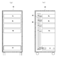
- FIG. 1 is a diagram illustrating a schematic configuration of a server system housed in a server rack 40.
- a server rack 40 In the server rack 40, a plurality of server units 4 (a to n) and uninterruptible power supply devices 10 stacked in multiple stages are housed.
- FIG. 1A is a front view showing a part cut away in order to show the configuration inside the server rack.
- FIG. 1B is a side view with a part cut away to show the internal configuration of the server rack.
- the server rack 40 is, for example, a 19-inch rack standardized by EIA (American Electronic Industry Association).
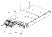
- the uninterruptible power supply 10 includes a metal shelf 11, a power unit 20, a battery unit 30, and a connection conductor module 6 described later.
- FIG. 2A is a front view of the shelf 11 of the uninterruptible power supply 10.
- the shelf 11 is provided with a plurality of storage chambers formed by dividing the width direction into four equal parts. The left two rows of storage chambers are further divided into two upper and lower stages. Accordingly, the shelf 11 is formed with four small storage chambers 12 (ad) and two large storage chambers 13 (a, b).
- the power supply units 20 (a to d) are stored in the four small storage chambers 12 (a to d) so as to be able to be taken in and out.
- the battery unit 30 (a, b) is stored in a removable manner.
- the power supply unit 20 includes an AC / DC converter 22 and a DC / DC converter 23 as in the conventional apparatus shown in FIG.
- the AC / DC converter 22 converts AC power supplied from a commercial power supply 3 into DC power.
- the DC / DC converter 23 converts the DC power that is the output of the AC / DC converter 22 into DC power of a voltage (for example, 12V) for supplying to the server units 4 (a to n) and outputs the DC power.
- the battery unit 30 includes a battery 32 and a bidirectional DC / DC converter 33. When the power supply unit 20 is operating, the DC / DC converter 33 charges the battery 32 with the DC power output from the power supply unit 20.
- the DC / DC converter 33 discharges the direct-current power charged in the battery 32 and supplies it to the load server 4.
- the DC output unit of the power supply unit 20 and the DC output unit of the battery unit 30 are electrically connected.
- a maximum of four power supply units 20 are stored in the storage chamber 12 of the shelf 11 and a maximum of two battery units 30 are stored in the storage chamber 13.
- the number of each storage is determined by the required server power capacity.
- a DC bus composed of a positive bar conductor 45 and a negative bar conductor 46 is provided.
- the output part of the uninterruptible power supply 10 is electrically connected to this DC bus.
- the DC power output from the uninterruptible power supply 10 is supplied to each server unit 4 (a to n) via the DC bus.
- a plurality of uninterruptible power supplies 10 may be housed in the server rack 40. In this case, each output part of each uninterruptible power supply 10 is connected in parallel to the DC bus.
- FIGS. 3 to 6 show the configuration of the uninterruptible power supply 10 in the order of assembly steps.
- FIG. 3 shows a state in the middle of inserting the four power supply units 20 (ad) and the two battery units 30 (a, b) into the shelf 11.
- FIG. 4 shows a state where insertion of each unit into the shelf 11 is completed.
- FIG. 5 is a view showing a state where the upper surface cover 16 at the rear part of the shelf 11 is removed and the connection conductor module 6 is extracted.
- connection conductor module 6 is mounted in the shelf 11 as will be described later.
- the connection conductor module 6 includes a module case 61 formed of an insulating material and a connection conductor portion having conductivity.
- the connection conductor portion includes connection terminals 62 (P, N), connection terminals 63 (P, N), lead terminals 64P, 65N, and connection conductors 64, 65.
- connection terminals 62 (P, N) for connecting to the output terminals of the respective power supply units 20 and connection terminals 63 (P for connecting to the output terminals of the battery unit 30).
- connection terminals 64P and 65N for outputting electric power to the outside are provided.
- connection terminal 62P and the connection terminal 63P are connection terminals on the positive potential side and are connected to the positive electrode connection conductor 64.
- connection terminal 62N and the connection terminal 63N are connection terminals on the negative potential side, and are connected to the negative electrode connection conductor 65.
- An output terminal is provided on the back of the power supply unit 20 and the battery unit 30. Each output terminal is fitted to the connection terminal 62 (P, N) and the connection terminal 63 (P, N) of the connection conductor module 6.
- the output power of the power supply unit 20 and the battery unit 30 is taken out from the lead terminals 64P, 64N and 65P, 65N.
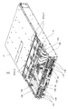
- FIG. 6 is an enlarged view of a portion where the shelf 11 and the connection conductor module 6 are inserted.
- the connection conductor module 6 is fixed to the shelf 11 without using screws. That is, the shelf 11 is provided with fitting grooves 11m on both side walls and a plurality of fitting protrusions 11n on the bottom wall. Further, the connecting conductor module 6 is provided with fitting pieces 61m that fit into the fitting grooves 11m on both side walls, and a fitting hole 61n (not shown) that fits with the fitting protrusion 11n on the bottom wall portion. .
- connection conductor module 6 When the connecting conductor module 6 is inserted into the shelf 11, the fitting piece 61 m of the connecting conductor module 6 is fitted into the fitting groove 11 m of the shelf 11, and the fitting hole 61 n of the connecting conductor module 6 is fitted into the shelf 11. It fits into the protrusion 11n. Thereby, the connection conductor module 6 inserted in the shelf 11 is firmly fixed to the shelf 11 without using a screw. Then, an upper cover 16 is put on the upper opening of the shelf 11 in which the connection conductor module 6 is inserted. Since the top cover 16 is fixed to the shelf 11 with screws, the connection conductor module 6 does not come out of the shelf 11.
- connection conductor portion in the connection conductor module 6 and the shelf 11 can be improved by fixing the connection conductor module 6 to the shelf 11 without using screws.
- insulation performance between the positive potential conductor portion and the negative potential conductor portion in the connection conductor module 6 can be enhanced.
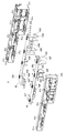
- connection conductor module 6 Next, the assembly process of the connection conductor module 6 will be described with reference to FIGS.
- FIG. 7 shows a state in which all components of the connection conductor module 6 are disassembled.
- the connection conductor module 6 includes a module case 61 made of an insulating material such as an insulating resin and a connection conductor portion having conductivity.
- the module case 61 is divided into a front case 61a and a rear case 61b.
- the front case 61a and the rear case 61b have front and rear surfaces that are open, form a rectangular cylindrical body, and include a plurality of terminal chambers that are partitioned by a partition wall.
- a part of the rear case 61b is inserted into the front case 61a, and both cases are fitted and joined together.
- the front case 61a and the rear case 61b are fixed without using screws.
- the front case 61a includes a plurality of elastic coupling pieces 61c provided with fitting holes 61d at the top end portion of the upper surface.
- the rear case 61b has a plurality of fitting protrusions 61e on the upper surface corresponding to the fitting holes 61d.
- the positive connection conductor 64 and the negative connection conductor 65 held by the module case 61 are bar-shaped conductors made of a copper flat plate or the like.
- a pair of lead terminals 64P and 65N for taking out DC power to the outside are integrally formed at both ends in the width direction of the connection conductors 64 and 65 or in the vicinity of both ends. Thereby, DC power can be taken out from either the left or right side of the uninterruptible power supply 10.
- connection terminals 62P and 63P are fastened and fixed to the positive connection conductor 64 by fixing screws 64k, respectively (see FIG. 8).
- the connection terminal 62P is a terminal connected to the positive output terminal of the power supply unit 20.
- the connection terminal 63P is a terminal connected to the positive output terminal of the battery unit 30.
- Two connection terminals 62N and 63N are fastened and fixed to the negative electrode connection conductor 65 by fixing screws 65k (see FIG. 8).
- the connection terminal 62 ⁇ / b> N is a terminal connected to the negative output terminal of the power supply unit 20.
- the connection terminal 63N is a terminal connected to the negative output terminal of the battery unit 30.
- connection terminals 62P and 62N are provided with four connection terminal pieces 62h and 62d, respectively, corresponding to the output terminals of the power supply units 20a to 20d arranged in two stages and two rows.
- connection terminals 63P and 63N are provided with two connection terminal pieces 63n and 63f respectively corresponding to the output terminals of the battery units 30a and 30b arranged in two rows.
- the front case 61 a has a plurality of terminal chambers 62 (ad), 63 (a, b) corresponding to the storage chambers 12 (ad), 13 (a, b) formed in the shelf 11. Is formed. In these terminal chambers 62 (a to d) and 63 (a and b), the tips of the connection terminal pieces 62 (d and h) and 63 (f and n) are projected to the front side of the front case 61a.
- the connection terminals 62 (P, N) and 63 (P, N) are accommodated.
- FIG. 8 shows a state in which the connection terminals 62P, 62N, 63P, and 63N are integrally fixed to the connection conductors 64 and 65, respectively. 8 is a perspective view seen from the opposite direction to FIG.
- connection conductors 64, 65 When the connection conductors 64, 65 are inserted into the front case 61a, the side edges of the connection terminals 62P, 62N, 63P, 63N coupled to the connection conductors 64, 65 are provided on the bottom wall portion of the front case 61a.
- the holding grooves 61g and 61h are fitted.
- the connection conductors 64, 65 are connected to the front case 61a. Held in place.
- the rear case 61b is inserted and fitted into the front case 61a.
- the fitting projection 61e of the rear case 61b enters the lower side of the elastic coupling piece 61c while elastically deforming and pushing up the elastic coupling piece 61c on the upper surface of the front case 61a.
- the fitting protrusion 61e of the rear case 61b reaches the position of the fitting hole 61d provided in the elastic coupling piece 61c of the front case 61a, it fits into the fitting hole 61d.
- connection conductors 64 and 65 incorporated in the front case 61 a are suppressed by the rear case 61 b from the rear surface side, and the connection conductors 64 and 65 are fixedly held by the module case 61.
- FIG. 9 shows a state in which the connection conductors 64 and 65 are inserted into the front case 61a.
- the positive electrode connection conductor 64 and the connection terminals 62P and 63P coupled thereto are shown by high density hatching.
- the negative electrode connection conductor 65 and the connection terminals 62N and 63N coupled to the negative electrode connection conductor 65 are indicated by low density hatching.
- the positive connection terminals 62P and 63P and the negative connection terminals 62N and 63N are alternately arranged in the width direction of the module case 61.
- the external appearance of the connecting conductor module 6 is shown in FIG.
- the module case 61 is configured by fitting a part of the rear case 61b into the front case 61a. Therefore, from the appearance, the trace (parting line) obtained by joining the front case 61a and the rear case 61b can hardly be seen, and the module case 61 shows a substantially integrated appearance.
- the appearance of the power supply unit 20 is shown in FIG.
- the power supply unit 20 houses an AC / DC converter 22 and a DC / DC converter 23 in a unit case 24. On the back surface of the power supply unit 20, two sets of a positive output terminal 21P and a negative output terminal 21N for outputting DC power are provided. The reason why two sets of the positive output terminal 21P and the negative output terminal 21N are provided is to reduce the current flowing per terminal and to reduce the contact resistance of the electrical connection portion with the connection conductor module 6.
- the output terminals 21P and 21N are formed as pinched female terminals.
- the connection terminal pieces 62 (d, h) and 63 (f, n) of the connection conductor module 6 connected to the output terminals 21P and 21N are formed as flat male terminals as shown in FIG.
- the output terminals 31P and 31N of the battery unit 30 are also formed as pinched female terminals having the same shape as the output terminals 21P and 21N of the power supply unit 20.
- connection terminal pieces 62 (d, h) of the connection conductor module 6 are inserted into the gaps between the output terminals 21P, 21N of the power supply unit 20 and are sandwiched between the output terminals 21P, 21N.
- electrical connection between the power supply unit 20 and the connection conductor module 6 is performed at the front opening of the module case 61.
- the connection terminal piece 63 (f, n) of the connection conductor module 6 is similarly inserted into the gap between the output terminals 31P and 31N of the battery unit 30 and sandwiched between the output terminals 31P and 31N. Thereby, the electrical connection between the battery unit 30 and the connection conductor module 6 is performed.
- connection conductor module 6 houses the power supply unit 20, the battery unit 30, and the connection conductor module 6 in the shelf 11.
- External output terminals 11P and 11N are provided on the back of the shelf 11 of the uninterruptible power supply 10.
- the external output terminals 11P and 11N are connected to the external lead terminals 64P and 65N of the connection conductor module 6 by the connection line 12.
- the external output terminals 11P and 11N of the uninterruptible power supply 10 are connected to the output terminals of the power supply unit 20 and the battery unit 30 in the shelf 11 via the connection line 12 and the connection conductor module 6.
- a flexible insulated wire as the connection line 12.
- connection line 12 includes two positive side connection lines 12a and 12b and two negative side connection lines 12c and 12d.
- the connection line 12 is configured by connecting the two connection lines in parallel as described above, the electrical resistance is halved, so that the resistance loss of the connection line 12 can be reduced. Thereby, the efficiency of the uninterruptible power supply 10 whole can be improved.
- FIG. 14 is a diagram showing a terminal structure included in the uninterruptible power supply 10 which is an embodiment of the present invention. This figure shows an embodiment of a terminal structure for connecting two connection lines 12a and 12b in parallel to the lead terminal 64P of the connection conductor module 6.
- connection terminals 13a and 13b formed in a square shape are connected to one end of the connection lines 12a and 12b.
- the two connection terminals 13a and 13b are arranged side by side on a lead terminal 64P formed in a square shape.
- the presser plate 14 formed in a square shape having substantially the same size as the lead terminal 64P is disposed on the connection terminals 13a and 13b.
- the lead terminal 64P sandwiching the connection terminals 13a and 13b and the presser plate 14 are fastened with equal pressure by the fastening bolts 15a and 15b. Thereby, the connection terminals 13a and 13b are fixed to the lead terminal 64P with equal pressure.
- the presser plate 14 is formed of a rectangular iron plate having high mechanical rigidity and high thermal conductivity, and has a surface plated with tin. With such a configuration, the entire contact surfaces of the two connection terminals 13a and 13b can be brought into contact with the lead terminal 64P with substantially equal pressure. For this reason, the contact resistance of the contact portion between the two connection terminals 13a and 13b and the lead terminal 64P can be reduced. As a result, it is possible to suppress the bias of the current flowing through the two connection terminals 13a and 13b and to reduce the loss caused by the contact resistance of the terminal portion.
- connection terminals 13c and 13d are connected to one ends of the connection lines 12c and 12d.
- the lead terminal 65N sandwiching the connection terminals 13c and 13d and the presser plate 14 are fastened with equal pressure by the fastening bolts 15a and 15b. Accordingly, the connection terminals 13c and 13d are fixed to the lead terminal 65N with an equal pressure. Therefore, the entire contact surfaces of the two connection terminals 13c and 13d can be brought into contact with the lead terminal 65N with substantially equal pressure. For this reason, the contact resistance of the contact portion between the two connection terminals 13c and 13d and the lead terminal 64P can be reduced. As a result, it is possible to suppress the bias of the current flowing through the two connection terminals 13c and 13d and to reduce the loss caused by the contact resistance of the terminal portion.
- the presser plate 14 may be made of a material other than the iron plate, such as stainless steel, as long as it has high mechanical rigidity and high thermal conductivity. Further, the presser plate 14 has a rising piece 14a formed by bending a part of the outer side at a right angle and rising several mm. The rising piece 14a functions to increase the rigidity of the presser plate 14 and to increase the heat dissipation effect by expanding the surface area. Thereby, the heat dissipation effect of the terminal connection part is improved, and the temperature rise of this part can be suppressed.
- the uninterruptible power supply 10 described here is configured by storing a power supply unit 20, a battery unit 30, and a connection conductor module 6 in a shelf 11, as in the uninterruptible power supply 10 described above.
- a power supply unit 20 a battery unit 30, and a connection conductor module 6 in a shelf 11, as in the uninterruptible power supply 10 described above.
- work for extracting a part of the power supply units 20 or the battery units 30 from the shelf 11 of the uninterruptible power supply 10 occurs. As shown in FIG.
- the cross-sectional area of the storage chamber 13 that stores the battery unit 30 is larger than the cross-sectional area of the storage chamber 12 that stores the power supply unit 20. Therefore, it is easy to insert a hand or a tool into the storage chamber 13 from which the battery unit 30 has been extracted. Moreover, since the cross-sectional area of the storage chamber 12 in which the power supply unit 20 is stored is small, it is not easy to insert a hand here. However, a thin rod-like tool such as a screwdriver can be inserted relatively easily.
- connection terminals 62 ⁇ / b> P, 62 ⁇ / b> N, 63 ⁇ / b> P, and 63 ⁇ / b> N of the connection conductor module 6 are exposed at the back of the storage chambers 12 and 13.
- the connection terminals 62P, 62N, 63P, and 63N of the connection conductor module 6 exposed the hands are brought into contact with these terminals. Risk of electric shock.
- connection terminals 62P, 62N, 63P, and 63N When a tool or the like is inserted into the storage chambers 12 and 13 from which the power supply unit 20 or the battery unit 30 has been removed, it comes into contact with the connection terminals 62P, 62N, 63P, and 63N, and a DC power supply short circuit accident occurs. There is danger.
- the uninterruptible power supply 10 shown in FIG. 15A uses a flapper mechanism 17 at a position between the insertion port of the storage chamber 13 and the front surface of the connection conductor module 6.
- a storage room shielding mechanism is provided.
- the flapper mechanism 17 includes a flapper 17a and a latch plate 18.
- the flapper 17 a has a flat plate shape and has a pair of support protrusions 17 b and 17 b that are formed to protrude outward at both upper ends thereof.
- the support protrusions 17 b and 17 b are inserted into bearing holes 13 a provided in the upper portions of both side walls of the storage chamber 13, so that the flapper 17 a is rotatably supported in the storage chamber 13.
- the flapper 17 a hangs vertically due to gravity and closes the front surface of the connection conductor module 6.
- the uninterruptible power supply 10 is provided with a latch plate 18 for preventing the flapper 17a from being rotated at this position even if a hand or the like is inserted into the storage chamber 13.
- the flapper mechanism 71 can prevent a human hand or the like inserted into the storage chamber 13 from touching the connection terminals 62P, 62N, 63P, 63N of the connection conductor module 6.
- FIG. 17 shows a detailed configuration of the flapper mechanism 17, (a) is a plan sectional view showing the flapper mechanism 17 in an enlarged manner, and (b) is a further enlarged view by partially cutting out the part. It is a perspective view shown.
- the flapper 17a hangs vertically and closes the front surface of the connection conductor module 6. At this time, the flapper 17a is latched by the latch plate 18 so as not to be pushed open by an external force.
- the latch plate 18 is made of a spring material, has a hook-shaped latch piece 18 a at the tip, and is disposed outside the storage chamber 13.
- the latch plate 18 is fixed to the outer wall of the storage chamber 13, that is, the outer wall of the shelf 11, at the base end opposite to the tip provided with the latch piece 18 a.
- the latch plate 18 includes a latch piece 18a at the tip, and two pressing protrusions 18b and 18c that protrude toward the storage chamber 13 at an intermediate portion.
- the latch plate 18 is pressed against the outer wall of the storage chamber 13 by its own spring force. For this reason, the latch piece 18 a provided at the tip and the pressing projections 18 b and 18 c provided at the intermediate portion enter the storage chamber 13 through the through holes provided in the outer wall of the storage chamber 13.
- the latch piece 18a that has entered the storage chamber 13 presses the back surface of the vertical flapper 17a, and locks the flapper 17a from the back surface side. For this reason, even if the pushing force P as shown by the arrow is applied to the front surface side of the flapper 17a, the rotation of the flapper 17a is prevented.
- FIG. 15B is a diagram in the middle of inserting the battery unit 30 into the storage chamber 13. This figure shows that the protrusion 31r provided on the upper part of the battery unit 30 has just reached the installation position of the flapper 17a.
- the pressing body 31 s provided on the side wall of the battery unit 30 comes into contact with the pressing protrusion 18 c of the latch plate 18 that has entered the storage chamber 13.
- the pressing projection 18 c comes into contact with the pressing projection 18 c
- the latch plate 18 is elastically deformed, and the pressing projection 18 c and the latch piece 18 a are pushed out of the storage chamber 13.
- the latch piece 18a is pushed out of the storage chamber 13, the locking of the flapper 17a is released, so that the flapper 17a can be rotated.
- the flapper 17a When the battery unit 30 is further pushed in, the flapper 17a is pushed by the protrusion 31r and rotates upward. The rotated flapper 17a is in a horizontal state at the top of the storage chamber 13 as shown in FIGS. 18 (a) and 18 (b). As a result, the interior of the storage chamber 13 is completely opened.
- the output terminals 31P, 31N of the battery unit 30 are joined to the connection terminal pieces 62P, 62N, 63P, 63N of the connection conductor module 6 and are electrically connected.
- the protrusion 31r at the tip of the battery unit 30 is detached from the flapper 17a. Then, the flapper 17a is not supported from below, rotates downward by its own weight, and hangs vertically. With the removal of the battery unit 30, the pressing of the latch plate 18 by the pressing body 31s of the battery unit 30 is also released. Then, the latch plate 18 returns to a position where it comes into contact with the outer wall of the shelf 11 by its own spring force. As a result, the latch piece 18 a enters the storage chamber 13 of the shelf 11. The latch piece 18a that has entered the storage chamber 13 of the shelf 11 locks the lower end of the flapper 17a to prevent the flapper 17a from rotating. In this way, the battery unit 30 can be inserted, and it is possible to reliably prevent human hands or tools inserted from the insertion port of the storage chamber 13 from coming into contact with the connection terminals of the connection conductor module 6.
- the storage chamber 12 for storing the power supply unit 20 has a small cross-sectional area, but a rod-like tool such as a screwdriver can be inserted. Therefore, in order to prevent such a contact accident due to a tool, a storage chamber shielding mechanism using a flapper mechanism 17 similar to the storage chamber 13 of the battery unit 30 may be provided in the storage chamber 12 in which the power supply unit 20 is stored. it can.
- Uninterruptible power supply 11 Shelf 12 (a, b, c, d): Connection line 13 (a, b, c, d): Connection terminal 14: Presser plate 14a: Launch piece 15 (a, b) : Fastening bolt 16: Top cover 20 (a, b, c, d): Power supply unit 30 (a, b): Battery unit 40: Server rack 4 (a to n): Server unit 6: Connection conductor module 61: Module Case 62 (P, N), 63 (P, N): Connection terminal 64P, 65N: Lead-out terminal
Landscapes
- Engineering & Computer Science (AREA)
- Theoretical Computer Science (AREA)
- General Engineering & Computer Science (AREA)
- Power Engineering (AREA)
- Physics & Mathematics (AREA)
- General Physics & Mathematics (AREA)
- Computer Hardware Design (AREA)
- Human Computer Interaction (AREA)
- Microelectronics & Electronic Packaging (AREA)
- Inverter Devices (AREA)
- Stand-By Power Supply Arrangements (AREA)
- Connections By Means Of Piercing Elements, Nuts, Or Screws (AREA)
- Charge And Discharge Circuits For Batteries Or The Like (AREA)
- Battery Mounting, Suspending (AREA)
Abstract
[Problem] To provide a power supply system in which power conversion units accommodated in a server rack are connected to each other within a shelf for accommodating said power conversion units, thereby facilitating connection with a DC bus line within the server rack. [Solution] Both a power supply unit for converting AC current into DC current and a battery unit for converting power stored in a battery into DC current and outputting the result are accommodated in one shelf in order to configure an uninterruptible power supply device, and the DC output terminals of the power supply unit and the DC output terminals of the battery unit are connected in parallel within the shelf by a connection conductor module that holds a connection conductor therein. The connection conductor module is configured from a module case formed from an insulating material and a connection conductor accommodated within the module case.
Description
この発明は、例えばデータセンタに設置されたサーバシステムに直流電力を供給する電源装置およびこの電源装置を備えるサーバシステムに関する。
The present invention relates to, for example, a power supply device that supplies DC power to a server system installed in a data center, and a server system including the power supply device.
図19は、特許文献1に示された従来の一般的なサーバシステム用電源システムの概略構成を示すものである。
FIG. 19 shows a schematic configuration of a conventional general server system power supply system disclosed in Patent Document 1.
この電源システムは、交流400Vの系統電源3に接続される無停電電源装置1と、この無停電電源装置1から出力される交流電力の電圧を絶縁して変換する変圧器2とを備える。
This power supply system includes an uninterruptible power supply 1 connected to an AC 400V system power supply 3 and a transformer 2 that insulates and converts the voltage of the AC power output from the uninterruptible power supply 1.
無停電電源装置1は、バッテリ1a,AC/DC変換器1b,DC/AC変換器1cを備える。このバッテリ1aは、系統電源3からの交流電力を直流電力に変換するAC/DC変換器1bにより充電される。そして、AC/DC変換器1bから出力される直流電力、またはバッテリ1aから放電される直流電力は、DC/AC変換器1cにより交流400Vの交流電力に変換される。
The uninterruptible power supply 1 includes a battery 1a, an AC / DC converter 1b, and a DC / AC converter 1c. The battery 1a is charged by an AC / DC converter 1b that converts AC power from the system power supply 3 into DC power. The DC power output from the AC / DC converter 1b or the DC power discharged from the battery 1a is converted into AC power of 400V AC by the DC / AC converter 1c.
DC/AC変換器1cから出力される400Vの交流電力は変圧器2により200Vまたは100Vの交流電力に変換される。さらに、変換された交流電力はサーバシステム4内の電力変換器5により低電圧(12V)の直流電力に変換される。電力変換器5は、AC/DC変換器5aとDC/DC変換器5bの直列回路で構成されている。この12Vの直流電力は負荷となる複数台のサーバ4a~4nに供給される。サーバシステム内の個別のサーバ4a~4nは、12Vの直流電力で動作する。
The 400V AC power output from the DC / AC converter 1c is converted by the transformer 2 into 200V or 100V AC power. Further, the converted AC power is converted into low voltage (12 V) DC power by the power converter 5 in the server system 4. The power converter 5 is composed of a series circuit of an AC / DC converter 5a and a DC / DC converter 5b. This 12V DC power is supplied to a plurality of servers 4a to 4n serving as loads. The individual servers 4a to 4n in the server system operate with 12V DC power.
複数台のサーバ4a~4nは、所定数ずつサーバラックに収納されてサーバシステムを構成する。電力変換器5は、各サーバシステムに対応して設けられる。そして電力変換器5は、各サーバが収納されているサーバラックに一体に収納される。
A plurality of servers 4a to 4n are stored in a server rack by a predetermined number to constitute a server system. The power converter 5 is provided corresponding to each server system. And the power converter 5 is integrally accommodated in the server rack in which each server is accommodated.
しかしながら、このような電源システムは、AC/DC変換器1b、5aやDC/DC変換器5b等の多くの変換器により、電力変換が行われるため、電力変換段数が多くなる。そのため、全体の電力変換効率が低下する。そこで、図20および図21に示すような直流電力供給のための電源システムが提案されている。
However, in such a power supply system, since power conversion is performed by many converters such as the AC / DC converters 1b and 5a and the DC / DC converter 5b, the number of power conversion stages increases. As a result, the overall power conversion efficiency decreases. Accordingly, a power supply system for supplying DC power as shown in FIGS. 20 and 21 has been proposed.
図20に示す電源システムは、無停電電源装置1のAC/DC変換器1bから出力される高電圧(400V)の直流電力を、直流用配電機器2aを介してサーバシステム4に給電する。そして、この高電圧(400V)の直流電力は、サーバシステム4内のDC/DC変換器5dにより12Vの低電圧の直流電力に変換される。この電源システムは、高電圧直流給電システム(HVDC)と称される。
The power supply system shown in FIG. 20 supplies high-voltage (400 V) DC power output from the AC / DC converter 1b of the uninterruptible power supply 1 to the server system 4 via the DC distribution device 2a. The high voltage (400V) direct current power is converted into a low voltage direct current power of 12V by the DC / DC converter 5d in the server system 4. This power supply system is referred to as a high voltage direct current power supply system (HVDC).
また、図21に示す電源システムでは、無停電電源装置1が、さらにDC/DC変換器1dを備えている。AC/DC変換器1bから出力される高電圧(400V)の直流電力は、DC/DC変換器1dにより、低電圧(48V)の直流電力に変換される。この低電圧(48V)の直流電力は、直流用配電機器2aを介してサーバシステム4に給電される。この低電圧(48V)の直流電力は、サーバシステム4内のDC/DC変換器5eにより、さらに低電圧(12V)の直流電力に変換される。この電源システムは、低電圧直流給電システムと称される。
In the power supply system shown in FIG. 21, the uninterruptible power supply 1 further includes a DC / DC converter 1d. The high voltage (400V) DC power output from the AC / DC converter 1b is converted into low voltage (48V) DC power by the DC / DC converter 1d. This low voltage (48V) DC power is supplied to the server system 4 via the DC power distribution equipment 2a. The low voltage (48V) DC power is further converted into low voltage (12V) DC power by the DC / DC converter 5e in the server system 4. This power supply system is referred to as a low voltage DC power supply system.
このような直流給電を行う電源システムは、電力変換の段数が少ないので、電力変換効率を高めることができる。
Since the power supply system that performs such DC power supply has a small number of power conversion stages, the power conversion efficiency can be increased.
しかし、図20に示す高電圧直流給電を行う電源システムにおいては、直流配電用遮断器2aとして高電圧の直流電力を遮断するための遮断器が必要である。高電圧の直流電力を遮断可能な遮断器は、大形であるだけでなく、直流高電圧(DC400V)配電に対する感電対策も必要となる。
However, in the power supply system that performs high-voltage DC power supply shown in FIG. 20, a circuit breaker for cutting off high-voltage DC power is required as the DC power distribution circuit breaker 2a. The circuit breaker capable of interrupting high-voltage DC power is not only large, but also requires electric shock countermeasures for DC high-voltage (DC400V) distribution.
一方、図21の電源システムは、低電圧の直流大電流を取り扱うので、配電線等の導体における損失や発熱が大きくなるという問題がある。
On the other hand, since the power supply system of FIG. 21 handles a low-voltage DC large current, there is a problem that loss and heat generation in a conductor such as a distribution line increase.
また、図19に示す電源システムでは、データセンタに、数百kW以上の大容量で大形の無停電電源装置1を集中配置している。そのため、データセンタに設置する無停電電源装置の設置スペースが大きくなる。しかも、無停電電源装置1に故障が発生した際は、すべてのサーバが停止することになり、システム全体の信頼性が低下するという問題がある。
Further, in the power supply system shown in FIG. 19, large uninterruptible power supply devices 1 having a large capacity of several hundred kW or more are centrally arranged in a data center. Therefore, the installation space for the uninterruptible power supply installed in the data center is increased. In addition, when a failure occurs in the uninterruptible power supply 1, all servers are stopped, and there is a problem that the reliability of the entire system is lowered.
このような従来の電源システムが有する問題点を解決するため、特許文献1には図22に示す電源システムが提案されている。
In order to solve such problems of the conventional power supply system, Patent Document 1 proposes a power supply system shown in FIG.
図22に示す電源システムは、交流の系統電源3から供給される200Vの交流電力をサーバシステム4に給電するものである。サーバシステム4のサーバラック40には、無停電電源装置10と複数のサーバ4a~4nが収納されている。無停電電源装置10は、電源ユニット20とバッテリユニット30により構成されている。電源ユニット20の電源回路部21は、系統電源3から供給される交流電力を直流電力に変換するAC/DC変換器22とこのAC/DC変換器22の出力の直流電力を12Vの直流電力に変換するDC/DC変換器23を備える。DC/DC変換器23から出力される12Vの直流電力がサーバ4a~4nに供給される。
The power supply system shown in FIG. 22 supplies 200 V AC power supplied from the AC system power supply 3 to the server system 4. The server rack 40 of the server system 4 houses the uninterruptible power supply 10 and a plurality of servers 4a to 4n. The uninterruptible power supply 10 includes a power supply unit 20 and a battery unit 30. The power supply circuit unit 21 of the power supply unit 20 includes an AC / DC converter 22 that converts AC power supplied from the system power supply 3 into DC power, and DC power output from the AC / DC converter 22 to 12V DC power. A DC / DC converter 23 for conversion is provided. 12V DC power output from the DC / DC converter 23 is supplied to the servers 4a to 4n.
また、バッテリユニット30のバッテリ回路部31は、直流電力を充電するバッテリ32と、双方向に直流電流の通流を行うDC/DC変換器33とを備える。バッテリ32は双方向のDC/DC変換器33を介して電源回路部21の出力に並列に接続される。バッテリ32は、双方向のDC/DC変換器33を通して、電源回路部21の直流出力によって充電されるとともに、充電した直流電力をDC/DC変換器33を介してサーバ4a~4nに供給する。
The battery circuit unit 31 of the battery unit 30 includes a battery 32 that charges DC power and a DC / DC converter 33 that allows DC current to flow in both directions. The battery 32 is connected in parallel to the output of the power supply circuit unit 21 via a bidirectional DC / DC converter 33. The battery 32 is charged by the direct current output of the power supply circuit unit 21 through the bidirectional DC / DC converter 33 and supplies the charged direct current power to the servers 4a to 4n via the DC / DC converter 33.
そして、このように構成された電源ユニット20とバッテリユニット30は、図23の(a)、(b)に示すように、共通のシェルフ50に収納されて、無停電電源装置10を構成している。電源ユニット20とバッテリユニット30のそれぞれの背面側に引き出された出力端子は、コネクタ44を介してサーバラック40内の電力母線42、43に接続される。電力母線42、43は、ここには図示しないサーバ(負荷)4の電源入力端子に接続される。
The power supply unit 20 and the battery unit 30 configured in this way are housed in a common shelf 50 as shown in FIGS. 23A and 23B to form the uninterruptible power supply 10. Yes. Output terminals drawn out to the back sides of the power supply unit 20 and the battery unit 30 are connected to power buses 42 and 43 in the server rack 40 via connectors 44. The power buses 42 and 43 are connected to a power input terminal of a server (load) 4 (not shown).
このように電源ユニットとバッテリユニットとをサーバとともにサーバラックに収納すると、無停電電源装置を別置する場合に比べてその設置スペースを低減することができる。さらに無停電電源装置が故障した場合、その影響がそのサーバラックに収納されたサーバだけに限定され、他のサーバラックのサーバには影響しない。したがって、サーバシステムの信頼性を高めることができる。
Storing the power supply unit and the battery unit together with the server in the server rack in this way can reduce the installation space as compared with the case where the uninterruptible power supply is installed separately. Further, when the uninterruptible power supply fails, the influence is limited to only the server stored in the server rack, and does not affect the servers in other server racks. Therefore, the reliability of the server system can be improved.
しかし、このような従来の無停電電源装置では、電源ユニットとバッテリユニットの背面において、各ユニットとサーバラック内の直流母線とをコネクタにより接続する必要がある。このコネクタの数は電源ユニットとバッテリユニットの数に応じて多数必要となるだけでなく、これらの接続に手間を要するという問題がある。
However, in such a conventional uninterruptible power supply, it is necessary to connect each unit and the DC bus in the server rack by a connector on the back of the power supply unit and the battery unit. The number of connectors is not only required depending on the number of power supply units and battery units, but also has a problem that it takes time to connect them.
この発明は、電源ユニットとバッテリユニットとを収納ケース内で相互に接続し、サーバラック内での直流母線との接続が容易となる電源システムを提供することを課題とするものである。
It is an object of the present invention to provide a power supply system in which a power supply unit and a battery unit are connected to each other in a storage case and can be easily connected to a DC bus in a server rack.
前記の課題を解決するため、この発明は、直流電力を給電する電源装置であって、前記電源装置は、前記直流電力を出力する複数の電力変換ユニット、前記複数の電力変換ユニットの出力端子を並列接続するための接続導体モジュール、前記複数の電力変換ユニットおよび前記接続導体モジュールを収納するシェルフを備え、前記接続導体モジュールは、絶縁材料で形成されたモジュールケースと前記モジュールケース内に収納される接続導体とで構成されていることを特徴とする。
In order to solve the above-described problem, the present invention provides a power supply device that supplies DC power, the power supply device including a plurality of power conversion units that output the DC power, and output terminals of the plurality of power conversion units. A connection conductor module for parallel connection, a plurality of power conversion units, and a shelf for storing the connection conductor module are provided, and the connection conductor module is stored in a module case formed of an insulating material and the module case It is characterized by comprising a connecting conductor.
この発明においては、前記モジュールケースは、前記複数の電力変換ユニットと対向する面に開口部を有し、前記接続導体は、前記複数の電力変換ユニットの出力端子と嵌合するための端子を備え、前記接続導体の前記端子は、前記開口部で前記複数の電力変換ユニットの出力端子と嵌合結合される。
In this invention, the module case has an opening in a surface facing the plurality of power conversion units, and the connection conductor includes a terminal for fitting with an output terminal of the plurality of power conversion units. The terminal of the connection conductor is fitted and coupled to the output terminals of the plurality of power conversion units at the opening.
また、この発明において、前記モジュールケースは、第1と第2のケースとから構成され、前記接続導体は、前記第1のケースと第2のケースとが嵌合されることにより、前記モジュールケース内に固定保持される。
In the present invention, the module case is composed of a first case and a second case, and the connection conductor is formed by fitting the first case and the second case into the module case. It is fixed and held inside.
そして、前記接続導体は、前記第1のケースもしくは前記第2のケースに設けられた保持溝に装着固定される。
The connection conductor is mounted and fixed in a holding groove provided in the first case or the second case.
さらに、この発明において、前記接続導体モジュールは、前記シェルフの側壁と底壁の少なくともいずれかに設けられた嵌合部と嵌合するための嵌合部を備えている。
Furthermore, in the present invention, the connection conductor module includes a fitting portion for fitting with a fitting portion provided on at least one of the side wall and the bottom wall of the shelf.
また、前記接続導体と前記シェルフとは、前記接続導体モジュールの上面、底面および両側面において、前記モジュールケースで絶縁されている。
Further, the connection conductor and the shelf are insulated by the module case on the upper surface, the bottom surface, and both side surfaces of the connection conductor module.
さらに、この発明において、前記直流電力を出力する複数の電力変換ユニットは、交流電源の電力を直流電力に変換して出力する電源ユニット、または、バッテリの電力を直流電力に変換して出力するバッテリユニットである。
Further, in the present invention, the plurality of power conversion units that output the DC power are a power supply unit that converts the power of the AC power source into DC power and outputs the power, or a battery that converts the power of the battery into DC power and outputs the power. Is a unit.
さらにまた、この発明において、前記接続導体は、前記電源装置の左右両側に、前記直流電力を外部へ引き出すための正極性と負極性の端子対を備えている。
この発明の電源装置により、サーバ用電源システムを構成することができる。この場合、電源装置をサーバの収容されたサーバラックに収納するのがよい。 Furthermore, in the present invention, the connection conductor includes positive and negative terminal pairs for drawing the DC power to the outside on both the left and right sides of the power supply device.
A server power supply system can be configured by the power supply device of the present invention. In this case, it is preferable to store the power supply device in a server rack in which the server is accommodated.
この発明によれば、電源装置は、電源ユニット,バッテリユニットおよび接続導体モジュールを備える。モジュールケースは、前記電源ユニットおよびバッテリユニットが収納されているシェルフに着脱可能に装着される。そして、電源ユニットとバッテリユニットとは、電源装置のシェルフに挿入されることで、それぞれの出力端子が接続導体モジュールの接続導体と電気的に並列接続される。接続導体は、絶縁材で形成されたモジュールケースにより保持される。この接続導体モジュールの接続端子を、電源ユニットおよびバッテリユニットの出力端子に嵌合結合することにより電源装置内の複数のユニットの並列接続を簡単に行うことができる。
According to this invention, the power supply device includes a power supply unit, a battery unit, and a connection conductor module. The module case is detachably attached to a shelf in which the power supply unit and the battery unit are stored. And a power supply unit and a battery unit are inserted in the shelf of a power supply device, and each output terminal is electrically connected in parallel with the connection conductor of a connection conductor module. The connection conductor is held by a module case formed of an insulating material. By connecting and connecting the connection terminals of the connection conductor module to the output terminals of the power supply unit and the battery unit, a plurality of units in the power supply device can be easily connected in parallel.
以下に、図1~図18を参照して、本発明の実施形態である無停電電源装置および電源システムについて説明する。以下で説明する電源システムの概略回路構成は、図22に示した電源システムの概略回路構成と同じである。図1~図18において、図19から図23を用いて説明した従来のサーバシステムと同じまたは等価な要素には、同じ符号を付している。
Hereinafter, an uninterruptible power supply and a power supply system according to an embodiment of the present invention will be described with reference to FIGS. The schematic circuit configuration of the power supply system described below is the same as the schematic circuit configuration of the power supply system shown in FIG. 1 to 18, the same or equivalent elements as those in the conventional server system described with reference to FIGS. 19 to 23 are denoted by the same reference numerals.
図1は、サーバラック40内に収められたサーバシステムの概略構成を示す図である。サーバラック40内には、多段に重ねられた複数のサーバユニット4(a~n)と無停電電源装置10が収められている。図1(a)は、サーバラック内部の構成を示すために一部を切断して示す正面図である。図1(b)は、サーバラック内部の構成を示すために一部を切断して示す側面図である。
サーバラック40は、例えば、EIA(米国電子工業会)によって規格化された19インチラックである。 FIG. 1 is a diagram illustrating a schematic configuration of a server system housed in aserver rack 40. In the server rack 40, a plurality of server units 4 (a to n) and uninterruptible power supply devices 10 stacked in multiple stages are housed. FIG. 1A is a front view showing a part cut away in order to show the configuration inside the server rack. FIG. 1B is a side view with a part cut away to show the internal configuration of the server rack.
Theserver rack 40 is, for example, a 19-inch rack standardized by EIA (American Electronic Industry Association).
サーバラック40は、例えば、EIA(米国電子工業会)によって規格化された19インチラックである。 FIG. 1 is a diagram illustrating a schematic configuration of a server system housed in a
The
無停電電源装置10は、金属製のシェルフ11とこのシェルフ11に収められた電源ユニット20、バッテリユニット30および後述する接続導体モジュール6等により構成されている。
図2(a)は、無停電電源装置10のシェルフ11を正面から見た図である。シェルフ11には、幅方向を4等分して形成された複数の収納室が設けられている。左の2列の収納室は、さらに上下2段に分割されている。したがって、シェルフ11には、4個の小収納室12(a~d)と2個の大収納室13(a、b)が形成されている。
4個の小収納室12(a~d)には、図2(b)に示すように、電源ユニット20(a~d)が出し入れ可能に収納される。また、大収納室13(a、b)には、バッテリユニット30(a、b)が、出し入れ可能に収納される。 Theuninterruptible power supply 10 includes a metal shelf 11, a power unit 20, a battery unit 30, and a connection conductor module 6 described later.
FIG. 2A is a front view of theshelf 11 of the uninterruptible power supply 10. The shelf 11 is provided with a plurality of storage chambers formed by dividing the width direction into four equal parts. The left two rows of storage chambers are further divided into two upper and lower stages. Accordingly, the shelf 11 is formed with four small storage chambers 12 (ad) and two large storage chambers 13 (a, b).
As shown in FIG. 2B, the power supply units 20 (a to d) are stored in the four small storage chambers 12 (a to d) so as to be able to be taken in and out. In the large storage chamber 13 (a, b), the battery unit 30 (a, b) is stored in a removable manner.
図2(a)は、無停電電源装置10のシェルフ11を正面から見た図である。シェルフ11には、幅方向を4等分して形成された複数の収納室が設けられている。左の2列の収納室は、さらに上下2段に分割されている。したがって、シェルフ11には、4個の小収納室12(a~d)と2個の大収納室13(a、b)が形成されている。
4個の小収納室12(a~d)には、図2(b)に示すように、電源ユニット20(a~d)が出し入れ可能に収納される。また、大収納室13(a、b)には、バッテリユニット30(a、b)が、出し入れ可能に収納される。 The
FIG. 2A is a front view of the
As shown in FIG. 2B, the power supply units 20 (a to d) are stored in the four small storage chambers 12 (a to d) so as to be able to be taken in and out. In the large storage chamber 13 (a, b), the battery unit 30 (a, b) is stored in a removable manner.
電源ユニット20は、図22に示した従来装置と同様に、AC/DC変換器22およびDC/DC変換器23とで構成される。AC/DC変換器22は、商用の系統電源3から給電される交流電力を直流電力に変換する。DC/DC変換器23は、AC/DC変換器22の出力である直流電力をサーバユニット4(a~n)に供給するための電圧(例えば12V)の直流電力に変換して出力する。バッテリユニット30はバッテリ32と双方向のDC/DC変換器33とで構成される。電源ユニット20が動作しているときは、DC/DC変換器33が、電源ユニット20から出力される直流電力をバッテリ32に充電する。一方、電源ユニット20が出力不能となったときは、DC/DC変換器33は、バッテリ32に充電された直流電力を放電して負荷のサーバ4に供給する。電源ユニット20の直流出力部とバッテリユニット30の直流出力部とは、電気的に接続されている。
The power supply unit 20 includes an AC / DC converter 22 and a DC / DC converter 23 as in the conventional apparatus shown in FIG. The AC / DC converter 22 converts AC power supplied from a commercial power supply 3 into DC power. The DC / DC converter 23 converts the DC power that is the output of the AC / DC converter 22 into DC power of a voltage (for example, 12V) for supplying to the server units 4 (a to n) and outputs the DC power. The battery unit 30 includes a battery 32 and a bidirectional DC / DC converter 33. When the power supply unit 20 is operating, the DC / DC converter 33 charges the battery 32 with the DC power output from the power supply unit 20. On the other hand, when the power supply unit 20 becomes unable to output, the DC / DC converter 33 discharges the direct-current power charged in the battery 32 and supplies it to the load server 4. The DC output unit of the power supply unit 20 and the DC output unit of the battery unit 30 are electrically connected.
ここに示す実施例では、シェルフ11の収納室12に電源ユニット20が最大4個収納され、収納室13にバッテリユニット30が最大2個収納される。それぞれの収納個数は、必要とするサーバの電源容量によって決定される。
In the embodiment shown here, a maximum of four power supply units 20 are stored in the storage chamber 12 of the shelf 11 and a maximum of two battery units 30 are stored in the storage chamber 13. The number of each storage is determined by the required server power capacity.
サーバラック40内には、サーバユニット4と無停電電源装置10以外に、正極バー導体45および負極バー導体46からなる直流母線が設けられている。この直流母線には、無停電電源装置10の出力部が電気的に接続されている。無停電電源装置10から出力される直流電力は、この直流母線を介して各サーバユニット4(a~n)に給電される。サーバラック40内には複数の無停電電源装置10が収められていても良い。この場合、各無停電電源装置10のそれぞれの出力部は、直流母線に並列に接続される。
In the server rack 40, in addition to the server unit 4 and the uninterruptible power supply 10, a DC bus composed of a positive bar conductor 45 and a negative bar conductor 46 is provided. The output part of the uninterruptible power supply 10 is electrically connected to this DC bus. The DC power output from the uninterruptible power supply 10 is supplied to each server unit 4 (a to n) via the DC bus. A plurality of uninterruptible power supplies 10 may be housed in the server rack 40. In this case, each output part of each uninterruptible power supply 10 is connected in parallel to the DC bus.
この発明の一実施形態である無停電電源装置10について、図3ないし図6を用いて説明する。
図3から図6は、無停電電源装置10の構成を、組み立て工程順に示したものである。 Anuninterruptible power supply 10 that is an embodiment of the present invention will be described with reference to FIGS.
3 to 6 show the configuration of theuninterruptible power supply 10 in the order of assembly steps.
図3から図6は、無停電電源装置10の構成を、組み立て工程順に示したものである。 An
3 to 6 show the configuration of the
図3は、4個の電源ユニット20(a~d)および2個のバッテリユニット30(a,b)をシェルフ11に挿入する途中の状態を示している。図4は、シェルフ11へ各ユニットの挿入を完了した状態を示している。
FIG. 3 shows a state in the middle of inserting the four power supply units 20 (ad) and the two battery units 30 (a, b) into the shelf 11. FIG. 4 shows a state where insertion of each unit into the shelf 11 is completed.
図5は、シェルフ11の後部の上面カバー16を外して、接続導体モジュール6を抜き出した状態を示す図である。
FIG. 5 is a view showing a state where the upper surface cover 16 at the rear part of the shelf 11 is removed and the connection conductor module 6 is extracted.
接続導体モジュール6は、後述するとおり、シェルフ11内に装着されている。接続導体モジュール6は、絶縁材で形成されたモジュールケース61と導電性を有する接続導体部とで構成されている。接続導体部は、接続端子62(P、N),接続端子63(P、N),引き出し端子64P、65Nおよび接続導体64,65で構成される。
接続導体モジュール6の前面側開口部には、各電源ユニット20の出力端子と接続するための接続端子62(P、N)、およびバッテリユニット30の出力端子と接続するための接続端子63(P、N)が備えられている。また、接続導体モジュール6の背面側には、電力を外部へ出力するための引き出し端子64P、65Nが備えられている。接続端子62Pと接続端子63Pとは、正電位側の接続端子であり、正極接続導体64と接続される。接続端子62Nと接続端子63Nとは、負電位側の接続端子であり、負極接続導体65と接続される。 Theconnection conductor module 6 is mounted in the shelf 11 as will be described later. The connection conductor module 6 includes a module case 61 formed of an insulating material and a connection conductor portion having conductivity. The connection conductor portion includes connection terminals 62 (P, N), connection terminals 63 (P, N), lead terminals 64P, 65N, and connection conductors 64, 65.
In the opening on the front surface side of theconnection conductor module 6, connection terminals 62 (P, N) for connecting to the output terminals of the respective power supply units 20 and connection terminals 63 (P for connecting to the output terminals of the battery unit 30). , N). On the back side of the connection conductor module 6, lead terminals 64P and 65N for outputting electric power to the outside are provided. The connection terminal 62P and the connection terminal 63P are connection terminals on the positive potential side and are connected to the positive electrode connection conductor 64. The connection terminal 62N and the connection terminal 63N are connection terminals on the negative potential side, and are connected to the negative electrode connection conductor 65.
接続導体モジュール6の前面側開口部には、各電源ユニット20の出力端子と接続するための接続端子62(P、N)、およびバッテリユニット30の出力端子と接続するための接続端子63(P、N)が備えられている。また、接続導体モジュール6の背面側には、電力を外部へ出力するための引き出し端子64P、65Nが備えられている。接続端子62Pと接続端子63Pとは、正電位側の接続端子であり、正極接続導体64と接続される。接続端子62Nと接続端子63Nとは、負電位側の接続端子であり、負極接続導体65と接続される。 The
In the opening on the front surface side of the
電源ユニット20とバッテリユニット30の背面には、出力端子が備えられている。それぞれの出力端子が、接続導体モジュール6の接続端子62(P、N)および接続端子63(P、N)と嵌合する。
An output terminal is provided on the back of the power supply unit 20 and the battery unit 30. Each output terminal is fitted to the connection terminal 62 (P, N) and the connection terminal 63 (P, N) of the connection conductor module 6.
電源ユニット20およびバッテリユニット30の出力電力は、引き出し端子64P、64Nおよび65P、65Nから外部に取り出される。
The output power of the power supply unit 20 and the battery unit 30 is taken out from the lead terminals 64P, 64N and 65P, 65N.
図6は、シェルフ11と接続導体モジュール6の挿入部分の拡大図である。接続導体モジュール6は、ネジを使用しないでシェルフ11に固定される。すなわち、シェルフ11には、両側壁に嵌合溝11mが設けられているとともに、底壁に複数の嵌合突起11nが設けられている。また、接続導体モジュール6には、嵌合溝11mに嵌り合う嵌合片61mが両側壁に設けられるとともに、底壁部に嵌合突起11nと嵌り合う嵌合孔61n(不図示)が設けられる。
FIG. 6 is an enlarged view of a portion where the shelf 11 and the connection conductor module 6 are inserted. The connection conductor module 6 is fixed to the shelf 11 without using screws. That is, the shelf 11 is provided with fitting grooves 11m on both side walls and a plurality of fitting protrusions 11n on the bottom wall. Further, the connecting conductor module 6 is provided with fitting pieces 61m that fit into the fitting grooves 11m on both side walls, and a fitting hole 61n (not shown) that fits with the fitting protrusion 11n on the bottom wall portion. .
接続導体モジュール6がシェルフ11に挿入されると、接続導体モジュール6の嵌合片61mがシェルフ11の嵌合溝11mに嵌合し、接続導体モジュール6の嵌合孔61nがシェルフ11の嵌合突起11nに嵌合する。これにより、シェルフ11に挿入された接続導体モジュール6が、ネジを用いることなく、シェルフ11に強固に固定される。そして、接続導体モジュール6の挿入されたシェルフ11の上部開口には、上面カバー16が被せられる。上面カバー16は、シェルフ11にネジで固定されるので、接続導体モジュール6がシェルフ11から抜け出ることはない。
When the connecting conductor module 6 is inserted into the shelf 11, the fitting piece 61 m of the connecting conductor module 6 is fitted into the fitting groove 11 m of the shelf 11, and the fitting hole 61 n of the connecting conductor module 6 is fitted into the shelf 11. It fits into the protrusion 11n. Thereby, the connection conductor module 6 inserted in the shelf 11 is firmly fixed to the shelf 11 without using a screw. Then, an upper cover 16 is put on the upper opening of the shelf 11 in which the connection conductor module 6 is inserted. Since the top cover 16 is fixed to the shelf 11 with screws, the connection conductor module 6 does not come out of the shelf 11.
接続導体モジュール6が、ネジを用いることなく、シェルフ11に固定されることにより、接続導体モジュール6内の接続導体部とシェルフ11間の絶縁性能を高めることができる。併せて、接続導体モジュール6内の正電位導体部と負電位導体部の間の絶縁性能を高めることができる。
The insulation performance between the connection conductor portion in the connection conductor module 6 and the shelf 11 can be improved by fixing the connection conductor module 6 to the shelf 11 without using screws. In addition, the insulation performance between the positive potential conductor portion and the negative potential conductor portion in the connection conductor module 6 can be enhanced.
次に、接続導体モジュール6の組立工程を、図7ないし図10を用いて説明する。
Next, the assembly process of the connection conductor module 6 will be described with reference to FIGS.
まず、図7に、接続導体モジュール6の全部品が分解された状態を示す。
First, FIG. 7 shows a state in which all components of the connection conductor module 6 are disassembled.
接続導体モジュール6は、絶縁樹脂などの絶縁材で構成されたモジュールケース61と、導電性を有する接続導体部とからなる。モジュールケース61は、前部ケース61aと後部ケース61bに分割して構成されている。前部ケース61aと後部ケース61bは、前、後面が開口され、矩形状の筒状体をなし、仕切壁により仕切られて形成された複数の端子室を内部に備える。前部ケース61a内に後部ケース61bの一部が挿入され、両ケースが一体に嵌合結合される。前部ケース61aと後部ケース61bの固定はネジによらないで行われる。そのため、前部ケース61aは、上面の先端部に嵌合孔61dの設けられた弾性結合片61cを複数備える。また、後部ケース61bは、この嵌合孔61dに対応してこれに嵌り合う複数の嵌合突起61eを上面に備える。
The connection conductor module 6 includes a module case 61 made of an insulating material such as an insulating resin and a connection conductor portion having conductivity. The module case 61 is divided into a front case 61a and a rear case 61b. The front case 61a and the rear case 61b have front and rear surfaces that are open, form a rectangular cylindrical body, and include a plurality of terminal chambers that are partitioned by a partition wall. A part of the rear case 61b is inserted into the front case 61a, and both cases are fitted and joined together. The front case 61a and the rear case 61b are fixed without using screws. Therefore, the front case 61a includes a plurality of elastic coupling pieces 61c provided with fitting holes 61d at the top end portion of the upper surface. The rear case 61b has a plurality of fitting protrusions 61e on the upper surface corresponding to the fitting holes 61d.
モジュールケース61によって保持される正極接続導体64および負極接続導体65は、銅平板等で構成されたバー状導電体である。この接続導体64、65の幅方向両端部または両端部近傍に、外部へ直流電力を取り出すための引き出し端子64P、65Nがそれぞれ1対ずつ一体に形成されている。これにより、無停電電源装置10の左右どちらの側からも直流電力の取り出しが可能となる。
The positive connection conductor 64 and the negative connection conductor 65 held by the module case 61 are bar-shaped conductors made of a copper flat plate or the like. A pair of lead terminals 64P and 65N for taking out DC power to the outside are integrally formed at both ends in the width direction of the connection conductors 64 and 65 or in the vicinity of both ends. Thereby, DC power can be taken out from either the left or right side of the uninterruptible power supply 10.
正極接続導体64には、それぞれ2個の接続端子62P,63Pが固定ネジ64kにより締め付け固定される(図8参照)。接続端子62Pは、電源ユニット20の正極出力端子に接続される端子である。接続端子63Pは、バッテリユニット30の正極出力端子に接続される端子である。
負極接続導体65には、それぞれ2個の接続端子62N,63Nが固定ネジ65kにより締め付け固定される(図8参照)。接続端子62Nは、電源ユニット20の負極出力端子に接続される端子である。接続端子63Nは、バッテリユニット30の負極出力端子に接続される端子である。
接続端子62P、62Nには、2段、2列に配置される電源ユニット20a~20dの各出力端子に対応して、接続端子片62hおよび62dがそれぞれ4個ずつ設けられている。一方、接続端子63P、63Nには、2列に配置されるバッテリユニット30a、30bの各出力端子に対応して、接続端子片63n、63fがそれぞれ2個ずつ設けられている。 Two connection terminals 62P and 63P are fastened and fixed to the positive connection conductor 64 by fixing screws 64k, respectively (see FIG. 8). The connection terminal 62P is a terminal connected to the positive output terminal of the power supply unit 20. The connection terminal 63P is a terminal connected to the positive output terminal of the battery unit 30.
Two connection terminals 62N and 63N are fastened and fixed to the negative electrode connection conductor 65 by fixing screws 65k (see FIG. 8). The connection terminal 62 </ b> N is a terminal connected to the negative output terminal of the power supply unit 20. The connection terminal 63N is a terminal connected to the negative output terminal of the battery unit 30.
The connection terminals 62P and 62N are provided with four connection terminal pieces 62h and 62d, respectively, corresponding to the output terminals of the power supply units 20a to 20d arranged in two stages and two rows. On the other hand, the connection terminals 63P and 63N are provided with two connection terminal pieces 63n and 63f respectively corresponding to the output terminals of the battery units 30a and 30b arranged in two rows.
負極接続導体65には、それぞれ2個の接続端子62N,63Nが固定ネジ65kにより締め付け固定される(図8参照)。接続端子62Nは、電源ユニット20の負極出力端子に接続される端子である。接続端子63Nは、バッテリユニット30の負極出力端子に接続される端子である。
接続端子62P、62Nには、2段、2列に配置される電源ユニット20a~20dの各出力端子に対応して、接続端子片62hおよび62dがそれぞれ4個ずつ設けられている。一方、接続端子63P、63Nには、2列に配置されるバッテリユニット30a、30bの各出力端子に対応して、接続端子片63n、63fがそれぞれ2個ずつ設けられている。 Two
Two
The
前部ケース61aには、シェルフ11に形成された収納室12(a~d)、13(a、b)に対応して、複数の端子室62(a~d)、63(a、b)が形成されている。これらの端子室62(a~d)、63(a、b)に、接続端子片62(d、h)、63(f、n)の先端が前部ケース61aの前面側へ突出するように、接続端子62(P、N)、63(P、N)が収納される。
The front case 61 a has a plurality of terminal chambers 62 (ad), 63 (a, b) corresponding to the storage chambers 12 (ad), 13 (a, b) formed in the shelf 11. Is formed. In these terminal chambers 62 (a to d) and 63 (a and b), the tips of the connection terminal pieces 62 (d and h) and 63 (f and n) are projected to the front side of the front case 61a. The connection terminals 62 (P, N) and 63 (P, N) are accommodated.
このように、接続導体64、65にそれぞれ接続端子62P、62N、63P、63Nが一体的に固定された状態を図8に示す。なお図8は、図7とは逆方向からみた斜視図である。
FIG. 8 shows a state in which the connection terminals 62P, 62N, 63P, and 63N are integrally fixed to the connection conductors 64 and 65, respectively. 8 is a perspective view seen from the opposite direction to FIG.
接続導体64、65が前部ケース61aに挿入されるとき、接続導体64、65に結合固定された接続端子62P、62N、63P、63Nの側辺が、前部ケース61aの底壁部に設けられた保持溝61g、61hに嵌め込まれる。接続端子62P、62N、63P、63Nの側辺が前部ケース61aの底壁部に設けられた保持溝61g、61hに嵌合することにより、接続導体64、65が、前部ケース61a内の所定位置に保持される。
When the connection conductors 64, 65 are inserted into the front case 61a, the side edges of the connection terminals 62P, 62N, 63P, 63N coupled to the connection conductors 64, 65 are provided on the bottom wall portion of the front case 61a. The holding grooves 61g and 61h are fitted. By connecting the side edges of the connection terminals 62P, 62N, 63P, 63N to the holding grooves 61g, 61h provided in the bottom wall portion of the front case 61a, the connection conductors 64, 65 are connected to the front case 61a. Held in place.
接続導体64、65を前部ケース61aに挿入された後、後部ケース61bが前部ケース61aに挿入嵌合される。この際、後部ケース61bの嵌合突起61eが、前部ケース61aの上面の弾性結合片61cを弾性変形させて押し上げながら、弾性結合片61cの下側に入り込む。後部ケース61bの嵌合突起61eは、前部ケース61aの弾性結合片61cに設けられた嵌合孔61dの位置に達すると、嵌合孔61dに嵌合する。嵌合孔61dと嵌合突起61eとが嵌合することにより、前部ケース61aと後部ケース61bとが結合固定され、一体的なモジュールケース61が形成される。これにより、前部ケース61aに組み込まれた接続導体64、65が後面側から後部ケース61bによって抑えられ、接続導体64、65がモジュールケース61によって固定的に保持される。
After the connecting conductors 64 and 65 are inserted into the front case 61a, the rear case 61b is inserted and fitted into the front case 61a. At this time, the fitting projection 61e of the rear case 61b enters the lower side of the elastic coupling piece 61c while elastically deforming and pushing up the elastic coupling piece 61c on the upper surface of the front case 61a. When the fitting protrusion 61e of the rear case 61b reaches the position of the fitting hole 61d provided in the elastic coupling piece 61c of the front case 61a, it fits into the fitting hole 61d. When the fitting hole 61d and the fitting protrusion 61e are fitted, the front case 61a and the rear case 61b are coupled and fixed to form an integral module case 61. Thereby, the connection conductors 64 and 65 incorporated in the front case 61 a are suppressed by the rear case 61 b from the rear surface side, and the connection conductors 64 and 65 are fixedly held by the module case 61.
接続導体64、65が前部ケース61aに挿入された状態を図9に示す。この図9において、正極接続導体64およびこれに結合された接続端子62P、63Pは、密度の高いハッチングで示されている。そして、負極接続導体65およびこれに結合された接続端子62N、63Nは、密度の低いハッチングで示されている。
FIG. 9 shows a state in which the connection conductors 64 and 65 are inserted into the front case 61a. In FIG. 9, the positive electrode connection conductor 64 and the connection terminals 62P and 63P coupled thereto are shown by high density hatching. The negative electrode connection conductor 65 and the connection terminals 62N and 63N coupled to the negative electrode connection conductor 65 are indicated by low density hatching.
図9に示すように、正極の接続端子62P、63Pと負極の接続端子62N、63Nとは、モジュールケース61の幅方向に交互に配置される。
As shown in FIG. 9, the positive connection terminals 62P and 63P and the negative connection terminals 62N and 63N are alternately arranged in the width direction of the module case 61.
接続導体モジュール6の外観を図10に示す。モジュールケース61は、前部ケース61aに後部ケース61bの一部が嵌め込まれて構成されている。したがって、外観からは、前部ケース61aと後部ケース61bとを結合した形跡(分割線)をほとんど見ることができず、モジュールケース61は、ほぼ一体的な外見を示す。
The external appearance of the connecting conductor module 6 is shown in FIG. The module case 61 is configured by fitting a part of the rear case 61b into the front case 61a. Therefore, from the appearance, the trace (parting line) obtained by joining the front case 61a and the rear case 61b can hardly be seen, and the module case 61 shows a substantially integrated appearance.
電源ユニット20の外観を図11に示す。
The appearance of the power supply unit 20 is shown in FIG.
電源ユニット20は、ユニットケース24内に、AC/DC変換器22、DC/DC変換器23を収納している。電源ユニット20の背面には、直流電力を出力するための正極出力端子21Pと負極出力端子21Nとが、2組備えられている。正極出力端子21Pと負極出力端子21Nとを2組備えるのは、1端子当たりに通電する電流を低減するためと、接続導体モジュール6との電気的接続部の接触抵抗を低減するためである。
The power supply unit 20 houses an AC / DC converter 22 and a DC / DC converter 23 in a unit case 24. On the back surface of the power supply unit 20, two sets of a positive output terminal 21P and a negative output terminal 21N for outputting DC power are provided. The reason why two sets of the positive output terminal 21P and the negative output terminal 21N are provided is to reduce the current flowing per terminal and to reduce the contact resistance of the electrical connection portion with the connection conductor module 6.
出力端子21P、21Nは、挟持型の雌端子に形成されている。出力端子21P、21Nと接続される接続導体モジュール6の接続端子片62(d、h)、63(f、n)は、図10に示すように平板の雄型端子に形成されている。また、図示しないが、バッテリユニット30の出力端子31P、31Nも、電源ユニット20の出力端子21Pおよび21Nと同じ形状の挟持型の雌端子に形成されている。
The output terminals 21P and 21N are formed as pinched female terminals. The connection terminal pieces 62 (d, h) and 63 (f, n) of the connection conductor module 6 connected to the output terminals 21P and 21N are formed as flat male terminals as shown in FIG. Although not shown, the output terminals 31P and 31N of the battery unit 30 are also formed as pinched female terminals having the same shape as the output terminals 21P and 21N of the power supply unit 20.
接続導体モジュール6が無停電電源装置10のシェルフ11に挿入、固定された状態を、図12(a)、(b)に示す。接続導体モジュール6の接続端子片62(d、h)が、電源ユニット20の出力端子21P、21Nの間隙に挿入されて出力端子21P、21Nにより挟持される。これにより、電源ユニット20と接続導体モジュール6の間の電気的な接続が、モジュールケース61の前面開口部において行われる。図示しないが、接続導体モジュール6の接続端子片63(f、n)が、同様に、バッテリユニット30の出力端子31P,31Nの間隙に挿入されて出力端子31P,31Nにより挟持される。これにより、バッテリユニット30と接続導体モジュール6の間の電気的な接続が行われる。
The state where the connection conductor module 6 is inserted and fixed to the shelf 11 of the uninterruptible power supply 10 is shown in FIGS. The connection terminal pieces 62 (d, h) of the connection conductor module 6 are inserted into the gaps between the output terminals 21P, 21N of the power supply unit 20 and are sandwiched between the output terminals 21P, 21N. As a result, electrical connection between the power supply unit 20 and the connection conductor module 6 is performed at the front opening of the module case 61. Although not shown, the connection terminal piece 63 (f, n) of the connection conductor module 6 is similarly inserted into the gap between the output terminals 31P and 31N of the battery unit 30 and sandwiched between the output terminals 31P and 31N. Thereby, the electrical connection between the battery unit 30 and the connection conductor module 6 is performed.
次に、接続導体モジュール6と無停電電源装置10との間の接続構造について、図13および図14を参照して説明する。無停電電源装置10は、上述したとおり、シェルフ11内に電源ユニット20、バッテリユニット30、接続導体モジュール6を収納する。
Next, a connection structure between the connection conductor module 6 and the uninterruptible power supply 10 will be described with reference to FIGS. 13 and 14. As described above, the uninterruptible power supply 10 houses the power supply unit 20, the battery unit 30, and the connection conductor module 6 in the shelf 11.
無停電電源装置10のシェルフ11の背面には、外部出力端子11P、11Nが備えられている。外部出力端子11P、11Nは、接続線12によって、接続導体モジュール6の外部引き出し端子64P、65Nと接続される。これによって、無停電電源装置10の外部出力端子11P、11Nが、接続線12と接続導体モジュール6とを介して、シェルフ11内の電源ユニット20、バッテリユニット30の出力端子に接続される。外部出力端子11P、11Nと接続導体モジュール6の外部引き出し端子64P、65Nとの接続作業を容易にするため、接続線12としては、可撓性を有する絶縁電線を使用するのがよい。
External output terminals 11P and 11N are provided on the back of the shelf 11 of the uninterruptible power supply 10. The external output terminals 11P and 11N are connected to the external lead terminals 64P and 65N of the connection conductor module 6 by the connection line 12. Accordingly, the external output terminals 11P and 11N of the uninterruptible power supply 10 are connected to the output terminals of the power supply unit 20 and the battery unit 30 in the shelf 11 via the connection line 12 and the connection conductor module 6. In order to facilitate the connection work between the external output terminals 11P and 11N and the external lead terminals 64P and 65N of the connection conductor module 6, it is preferable to use a flexible insulated wire as the connection line 12.
無停電電源装置10は、低電圧かつ大電流の直流電力を出力する。したがって、接続線12は、図13に示すように、2本の正極側接続線12a、12bと2本の負極側接続線12c、12dで構成される。このように2本の接続線を並列接続して接続線12を構成すると電気抵抗が半減されるので、接続線12の抵抗損失を低減することができる。これにより、無停電電源装置10全体の効率を高めることができる。
The uninterruptible power supply 10 outputs low-voltage and large-current DC power. Therefore, as shown in FIG. 13, the connection line 12 includes two positive side connection lines 12a and 12b and two negative side connection lines 12c and 12d. When the connection line 12 is configured by connecting the two connection lines in parallel as described above, the electrical resistance is halved, so that the resistance loss of the connection line 12 can be reduced. Thereby, the efficiency of the uninterruptible power supply 10 whole can be improved.
図14は、本発明の一実施形態である無停電電源装置10が備える端子構造を示す図である。この図は、接続導体モジュール6の引き出し端子64Pに2本の接続線12a、12bを並列接続するための端子構造の実施例を示している。
FIG. 14 is a diagram showing a terminal structure included in the uninterruptible power supply 10 which is an embodiment of the present invention. This figure shows an embodiment of a terminal structure for connecting two connection lines 12a and 12b in parallel to the lead terminal 64P of the connection conductor module 6.
接続線12a、12bの一端には、方形状に形成された接続端子13a、13bが接続されている。2つの接続端子13a、13bは、方形状に形成された引き出し端子64P上に並べて配置される。さらに、接続端子13a、13bの上に、引き出し端子64Pとほぼ同じ大きさの方形状に形成された押え板14が配置される。接続端子13a、13bを挟み込んだ引き出し端子64Pと押え板14とが、締結ボルト15a、15bによって、均等な圧力で締結される。これにより、接続端子13a、13bが、均等な圧力で引き出し端子64Pに固定される。
The connection terminals 13a and 13b formed in a square shape are connected to one end of the connection lines 12a and 12b. The two connection terminals 13a and 13b are arranged side by side on a lead terminal 64P formed in a square shape. Furthermore, the presser plate 14 formed in a square shape having substantially the same size as the lead terminal 64P is disposed on the connection terminals 13a and 13b. The lead terminal 64P sandwiching the connection terminals 13a and 13b and the presser plate 14 are fastened with equal pressure by the fastening bolts 15a and 15b. Thereby, the connection terminals 13a and 13b are fixed to the lead terminal 64P with equal pressure.
押え板14は、機械的剛性が高くかつ熱伝導性が高い長方形状の鉄板で形成されており、表面に錫めっきが施されている。
このような構成にすると、2つの接続端子13a、13bの接触面全体をほぼ均等な圧力で引き出し端子64Pに接触させることができる。このため、2つの接続端子13a、13bと引き出し端子64Pの接触部分の接触抵抗を低減することができる。その結果、2つの接続端子13a、13bに流れる電流の偏りが抑えられるとともに、端子部の接触抵抗によって発生する損失を低減することが可能となる。 Thepresser plate 14 is formed of a rectangular iron plate having high mechanical rigidity and high thermal conductivity, and has a surface plated with tin.
With such a configuration, the entire contact surfaces of the two connection terminals 13a and 13b can be brought into contact with the lead terminal 64P with substantially equal pressure. For this reason, the contact resistance of the contact portion between the two connection terminals 13a and 13b and the lead terminal 64P can be reduced. As a result, it is possible to suppress the bias of the current flowing through the two connection terminals 13a and 13b and to reduce the loss caused by the contact resistance of the terminal portion.
このような構成にすると、2つの接続端子13a、13bの接触面全体をほぼ均等な圧力で引き出し端子64Pに接触させることができる。このため、2つの接続端子13a、13bと引き出し端子64Pの接触部分の接触抵抗を低減することができる。その結果、2つの接続端子13a、13bに流れる電流の偏りが抑えられるとともに、端子部の接触抵抗によって発生する損失を低減することが可能となる。 The
With such a configuration, the entire contact surfaces of the two
同様に、接続線12c、12dの一端に方形状の接続端子13c,13dが接続されている。この接続端子13c,13dを挟み込んだ引き出し端子65Nと押え板14とが、締結ボルト15a、15bによって、均等な圧力で締結される。これにより、接続端子13c,13dが、均等な圧力で引き出し端子65Nに固定される。
したがって、2つの接続端子13c,13dの接触面全体をほぼ均等な圧力で引き出し端子65Nに接触させることができる。このため、2つの接続端子13c,13dと引き出し端子64Pの接触部分の接触抵抗を低減することができる。その結果、2つの接続端子13c,13dに流れる電流の偏りが抑えられるとともに、端子部の接触抵抗によって発生する損失を低減することが可能となる。 Similarly, rectangular connection terminals 13c and 13d are connected to one ends of the connection lines 12c and 12d. The lead terminal 65N sandwiching the connection terminals 13c and 13d and the presser plate 14 are fastened with equal pressure by the fastening bolts 15a and 15b. Accordingly, the connection terminals 13c and 13d are fixed to the lead terminal 65N with an equal pressure.
Therefore, the entire contact surfaces of the two connection terminals 13c and 13d can be brought into contact with thelead terminal 65N with substantially equal pressure. For this reason, the contact resistance of the contact portion between the two connection terminals 13c and 13d and the lead terminal 64P can be reduced. As a result, it is possible to suppress the bias of the current flowing through the two connection terminals 13c and 13d and to reduce the loss caused by the contact resistance of the terminal portion.
したがって、2つの接続端子13c,13dの接触面全体をほぼ均等な圧力で引き出し端子65Nに接触させることができる。このため、2つの接続端子13c,13dと引き出し端子64Pの接触部分の接触抵抗を低減することができる。その結果、2つの接続端子13c,13dに流れる電流の偏りが抑えられるとともに、端子部の接触抵抗によって発生する損失を低減することが可能となる。 Similarly, rectangular connection terminals 13c and 13d are connected to one ends of the
Therefore, the entire contact surfaces of the two connection terminals 13c and 13d can be brought into contact with the
押え板14は、機械的剛性が高くかつ熱伝導性が高ければ、鉄板以外の他の材料、例えばステンレスで形成されていても良い。さらに、押え板14には、外側辺の一部を直角に折り曲げて数mm立ち上げた立ち上げ片14aが形成されている。この立ち上げ片14aは、押え板14の剛性を高めるとともに、表面積を拡大して放熱効果を高める働きをする。これにより、端子接続部分の放熱効果が向上し、この部分の温度上昇を抑えることができる。
The presser plate 14 may be made of a material other than the iron plate, such as stainless steel, as long as it has high mechanical rigidity and high thermal conductivity. Further, the presser plate 14 has a rising piece 14a formed by bending a part of the outer side at a right angle and rising several mm. The rising piece 14a functions to increase the rigidity of the presser plate 14 and to increase the heat dissipation effect by expanding the surface area. Thereby, the heat dissipation effect of the terminal connection part is improved, and the temperature rise of this part can be suppressed.
次に、感電事故および短絡事故の発生を防止するために、この発明の一実施形態である無停電電源装置10が備える機構を、図15~図18を参照して説明する。ここで説明する無停電電源装置10は、上述した無停電電源装置10と同じく、シェルフ11に電源ユニット20、バッテリユニット30、接続導体モジュール6を収納して構成されている。この無停電電源装置10の保守・点検時には、一般に、無停電電源装置10のシェルフ11から一部の電源ユニット20もしくはバッテリユニット30を抜き出す作業が発生する。
図2に示すように、バッテリユニット30を収納する収納室13の断面積は、電源ユニット20を収納する収納室12の断面積よりも大きい。そのため、バッテリユニット30を抜き出した収納室13には、人手もしくは工具を挿入することが容易である。
また、電源ユニット20を収納する収納室12の断面積は小さいので、ここへ人手を挿入することは容易ではない。しかし、ねじ回しのような細い棒状の工具は、比較的容易に挿入することができる。 Next, a mechanism provided in theuninterruptible power supply 10 according to one embodiment of the present invention in order to prevent the occurrence of an electric shock accident and a short-circuit accident will be described with reference to FIGS. The uninterruptible power supply 10 described here is configured by storing a power supply unit 20, a battery unit 30, and a connection conductor module 6 in a shelf 11, as in the uninterruptible power supply 10 described above. At the time of maintenance / inspection of the uninterruptible power supply 10, generally, work for extracting a part of the power supply units 20 or the battery units 30 from the shelf 11 of the uninterruptible power supply 10 occurs.
As shown in FIG. 2, the cross-sectional area of thestorage chamber 13 that stores the battery unit 30 is larger than the cross-sectional area of the storage chamber 12 that stores the power supply unit 20. Therefore, it is easy to insert a hand or a tool into the storage chamber 13 from which the battery unit 30 has been extracted.
Moreover, since the cross-sectional area of the storage chamber 12 in which thepower supply unit 20 is stored is small, it is not easy to insert a hand here. However, a thin rod-like tool such as a screwdriver can be inserted relatively easily.
図2に示すように、バッテリユニット30を収納する収納室13の断面積は、電源ユニット20を収納する収納室12の断面積よりも大きい。そのため、バッテリユニット30を抜き出した収納室13には、人手もしくは工具を挿入することが容易である。
また、電源ユニット20を収納する収納室12の断面積は小さいので、ここへ人手を挿入することは容易ではない。しかし、ねじ回しのような細い棒状の工具は、比較的容易に挿入することができる。 Next, a mechanism provided in the
As shown in FIG. 2, the cross-sectional area of the
Moreover, since the cross-sectional area of the storage chamber 12 in which the
シェルフ11から電源ユニット20もしくはバッテリユニット30が抜去られると、収納室12、13の奥部に接続導体モジュール6の接続端子62P、62N、63P、63Nが露出する。このように接続導体モジュール6の接続端子62P、62N、63P、63Nが露出した状態で、収納室12、13にシェルフ11の前面から人手が挿入されると、人手がこれらの端子と接触して感電事故が発生する危険がある。また、電源ユニット20もしくはバッテリユニット30が抜去された収納室12、13に工具等が挿入されると、これが接続端子62P、62N、63P、63Nと接触して、直流電源の短絡事故が発生する危険がある。
When the power supply unit 20 or the battery unit 30 is removed from the shelf 11, the connection terminals 62 </ b> P, 62 </ b> N, 63 </ b> P, and 63 </ b> N of the connection conductor module 6 are exposed at the back of the storage chambers 12 and 13. In this manner, when a hand is inserted into the storage chambers 12 and 13 from the front surface of the shelf 11 with the connection terminals 62P, 62N, 63P, and 63N of the connection conductor module 6 exposed, the hands are brought into contact with these terminals. Risk of electric shock. Further, when a tool or the like is inserted into the storage chambers 12 and 13 from which the power supply unit 20 or the battery unit 30 has been removed, it comes into contact with the connection terminals 62P, 62N, 63P, and 63N, and a DC power supply short circuit accident occurs. There is danger.
このような危険を防止すために、図15(a)に示す無停電電源装置10では、収納室13の挿入口と接続導体モジュール6の前面との間の位置に、フラッパ機構17を用いた収納室遮蔽機構を設けている。フラッパ機構17は、フラッパ17aとラッチ板18とからなる。
フラッパ17aは、図17、18に詳細を示すように、平板状であり、その上部両端に外側へ突出形成された1対の支持突起17b、17bを有する。この支持突起17b、17bが収納室13の両側壁の上部に設けた軸受穴13aに挿入されることにより、フラッパ17aが収納室13内で、回動自在に支持される。 In order to prevent such a risk, theuninterruptible power supply 10 shown in FIG. 15A uses a flapper mechanism 17 at a position between the insertion port of the storage chamber 13 and the front surface of the connection conductor module 6. A storage room shielding mechanism is provided. The flapper mechanism 17 includes a flapper 17a and a latch plate 18.
As shown in detail in FIGS. 17 and 18, theflapper 17 a has a flat plate shape and has a pair of support protrusions 17 b and 17 b that are formed to protrude outward at both upper ends thereof. The support protrusions 17 b and 17 b are inserted into bearing holes 13 a provided in the upper portions of both side walls of the storage chamber 13, so that the flapper 17 a is rotatably supported in the storage chamber 13.
フラッパ17aは、図17、18に詳細を示すように、平板状であり、その上部両端に外側へ突出形成された1対の支持突起17b、17bを有する。この支持突起17b、17bが収納室13の両側壁の上部に設けた軸受穴13aに挿入されることにより、フラッパ17aが収納室13内で、回動自在に支持される。 In order to prevent such a risk, the
As shown in detail in FIGS. 17 and 18, the
図15(a)に示すように、収納室13からバッテリユニット30が抜去られると、フラッパ17aは、重力によって垂直に垂れさがり、接続導体モジュール6の前面を閉じる。
そして、無停電電源装置10は、収納室13に人手等が挿入されてもフラッパ17aがこの位置で回動されないようにするためのラッチ板18を備える。このフラッパ機構71により、収納室13内に挿入された人手等が、接続導体モジュール6の接続端子62P、62N、63P、63Nに触れるのを防止することができる。 As shown in FIG. 15A, when thebattery unit 30 is removed from the storage chamber 13, the flapper 17 a hangs vertically due to gravity and closes the front surface of the connection conductor module 6.
Theuninterruptible power supply 10 is provided with a latch plate 18 for preventing the flapper 17a from being rotated at this position even if a hand or the like is inserted into the storage chamber 13. The flapper mechanism 71 can prevent a human hand or the like inserted into the storage chamber 13 from touching the connection terminals 62P, 62N, 63P, 63N of the connection conductor module 6.
そして、無停電電源装置10は、収納室13に人手等が挿入されてもフラッパ17aがこの位置で回動されないようにするためのラッチ板18を備える。このフラッパ機構71により、収納室13内に挿入された人手等が、接続導体モジュール6の接続端子62P、62N、63P、63Nに触れるのを防止することができる。 As shown in FIG. 15A, when the
The
図17は、フラッパ機構17の詳細な構成を示すもので、(a)は、フラッパ機構17部分を拡大して示す平面断面図、(b)は、同部分を部分的に切り欠いてさらに拡大して示す斜視図である。
これらの図に示すように、フラッパ17aが、垂直に垂れ下がった状態となって、接続導体モジュール6の前面を閉じている。このとき、フラッパ17aは、外力によって押し開かれることがないようにラッチ板18によってラッチされる。
このラッチ板18は、ばね材で構成され、先端に鉤状のラッチ片18aを備え、収納室13の外側に配置される。このラッチ板18は、ラッチ片18aの設けられた先端とは反対側の基端部が、収納室13の外側壁、すなわちシェルフ11の外側壁に固定される。また、ラッチ板18は、先端にラッチ片18aを備えるほか、中間部に収納室13側に突出する2つの押圧突起18b、18cを備える。
収納室13からバッテリユニット20が抜去されてフラッパ17aが垂直に垂れ下がっているとき、ラッチ板18は、自身のばね力により収納室13の外側壁に押し付けられる。このため、先端に設けられたラッチ片18aと中間部に設けられた押圧突起18b、18cが、収納室13の外側壁に設けた貫通孔を通して、収納室13内に侵入する。
収納室13内に侵入したラッチ片18aは、垂直なフラッパ17aの背面を押圧して、フラッパ17aを背面側から係止する。このため、矢印で示すような押し込み力Pをフラッパ17aの前面側に加えても、フラッパ17aの回動が阻止される。 FIG. 17 shows a detailed configuration of theflapper mechanism 17, (a) is a plan sectional view showing the flapper mechanism 17 in an enlarged manner, and (b) is a further enlarged view by partially cutting out the part. It is a perspective view shown.
As shown in these drawings, theflapper 17a hangs vertically and closes the front surface of the connection conductor module 6. At this time, the flapper 17a is latched by the latch plate 18 so as not to be pushed open by an external force.
Thelatch plate 18 is made of a spring material, has a hook-shaped latch piece 18 a at the tip, and is disposed outside the storage chamber 13. The latch plate 18 is fixed to the outer wall of the storage chamber 13, that is, the outer wall of the shelf 11, at the base end opposite to the tip provided with the latch piece 18 a. The latch plate 18 includes a latch piece 18a at the tip, and two pressing protrusions 18b and 18c that protrude toward the storage chamber 13 at an intermediate portion.
When thebattery unit 20 is removed from the storage chamber 13 and the flapper 17a is hanging vertically, the latch plate 18 is pressed against the outer wall of the storage chamber 13 by its own spring force. For this reason, the latch piece 18 a provided at the tip and the pressing projections 18 b and 18 c provided at the intermediate portion enter the storage chamber 13 through the through holes provided in the outer wall of the storage chamber 13.
Thelatch piece 18a that has entered the storage chamber 13 presses the back surface of the vertical flapper 17a, and locks the flapper 17a from the back surface side. For this reason, even if the pushing force P as shown by the arrow is applied to the front surface side of the flapper 17a, the rotation of the flapper 17a is prevented.
これらの図に示すように、フラッパ17aが、垂直に垂れ下がった状態となって、接続導体モジュール6の前面を閉じている。このとき、フラッパ17aは、外力によって押し開かれることがないようにラッチ板18によってラッチされる。
このラッチ板18は、ばね材で構成され、先端に鉤状のラッチ片18aを備え、収納室13の外側に配置される。このラッチ板18は、ラッチ片18aの設けられた先端とは反対側の基端部が、収納室13の外側壁、すなわちシェルフ11の外側壁に固定される。また、ラッチ板18は、先端にラッチ片18aを備えるほか、中間部に収納室13側に突出する2つの押圧突起18b、18cを備える。
収納室13からバッテリユニット20が抜去されてフラッパ17aが垂直に垂れ下がっているとき、ラッチ板18は、自身のばね力により収納室13の外側壁に押し付けられる。このため、先端に設けられたラッチ片18aと中間部に設けられた押圧突起18b、18cが、収納室13の外側壁に設けた貫通孔を通して、収納室13内に侵入する。
収納室13内に侵入したラッチ片18aは、垂直なフラッパ17aの背面を押圧して、フラッパ17aを背面側から係止する。このため、矢印で示すような押し込み力Pをフラッパ17aの前面側に加えても、フラッパ17aの回動が阻止される。 FIG. 17 shows a detailed configuration of the
As shown in these drawings, the
The
When the
The
すなわち、フラッパ17aが垂直に垂れさがって接続導体モジュール6の前面を閉じるので、収納室13に人手や工具等を挿入しても、これらが誤って接続導体モジュール6の露出している接続端子に接触することを確実に防止することができる。
That is, since the flapper 17a hangs vertically and closes the front surface of the connection conductor module 6, even if a hand or a tool is inserted into the storage chamber 13, these are mistakenly connected to the connection terminals exposed in the connection conductor module 6. Contact can be reliably prevented.
図15(b)は、バッテリユニット30が収納室13に挿入される途中の図である。この図は、バッテリユニット30の上部に設けられた突起31rが、丁度、フラッパ17aの設置位置に達したところを示している。この状態では、図18(a)に示すように、バッテリユニット30の側壁に設けられた押圧体31sが、収納室13内に侵入しているラッチ板18の押圧突起18cと接触する。
押圧体31sが押圧突起18cに接触することにより、ラッチ板18が弾性変形して、押圧突起18cとラッチ片18aが収納室13の外側に押し出される。ラッチ片18aが収納室13の外側に押し出されると、フラッパ17aの係止が解除されるので、フラッパ17aは回動可能となる。 FIG. 15B is a diagram in the middle of inserting thebattery unit 30 into the storage chamber 13. This figure shows that the protrusion 31r provided on the upper part of the battery unit 30 has just reached the installation position of the flapper 17a. In this state, as shown in FIG. 18A, the pressing body 31 s provided on the side wall of the battery unit 30 comes into contact with the pressing protrusion 18 c of the latch plate 18 that has entered the storage chamber 13.
When thepressing body 31 s comes into contact with the pressing projection 18 c, the latch plate 18 is elastically deformed, and the pressing projection 18 c and the latch piece 18 a are pushed out of the storage chamber 13. When the latch piece 18a is pushed out of the storage chamber 13, the locking of the flapper 17a is released, so that the flapper 17a can be rotated.
押圧体31sが押圧突起18cに接触することにより、ラッチ板18が弾性変形して、押圧突起18cとラッチ片18aが収納室13の外側に押し出される。ラッチ片18aが収納室13の外側に押し出されると、フラッパ17aの係止が解除されるので、フラッパ17aは回動可能となる。 FIG. 15B is a diagram in the middle of inserting the
When the
ここで、バッテリユニット30を、さらに収納室13の奥へ押し込むと、図15(c)に示すように、バッテリユニット30の突起31rがフラッパ17aと接触する。この状態をより明確にするため、突起31rを含む部分を拡大して図16に示す。
Here, when the battery unit 30 is further pushed into the storage chamber 13, the protrusion 31r of the battery unit 30 comes into contact with the flapper 17a as shown in FIG. In order to clarify this state, the portion including the protrusion 31r is enlarged and shown in FIG.
バッテリユニット30をさらに押し込むと、フラッパ17aが突起31rに押されて上方へ回動する。回動したフラッパ17aは、図18(a)、(b)に示すように収納室13の上部で水平状態となる。これにより、収納室13内が完全に開いた状態となる。ここからさらにバッテリユニット30を押し込むことにより、バッテリユニット30の出力端子31P、31Nが接続導体モジュール6の接続端子片62P、62N、63P、63Nに接合し、電気的に接続される。
When the battery unit 30 is further pushed in, the flapper 17a is pushed by the protrusion 31r and rotates upward. The rotated flapper 17a is in a horizontal state at the top of the storage chamber 13 as shown in FIGS. 18 (a) and 18 (b). As a result, the interior of the storage chamber 13 is completely opened. By further pushing the battery unit 30 from here, the output terminals 31P, 31N of the battery unit 30 are joined to the connection terminal pieces 62P, 62N, 63P, 63N of the connection conductor module 6 and are electrically connected.
バッテリユニット30が収納室13から抜去られると、バッテリユニット30の先端の突起31rがフラッパ17aから外れる。そうすると、フラッパ17aは、下方からの支持がなくなり、自重で下方へ回動し、垂直に垂れ下がる。バッテリユニット30の抜去にともなって、バッテリユニット30の押圧体31sによるラッチ板18の押圧も解除される。そうすると、ラッチ板18が自身のバネ力によりシェルフ11の外壁に接触する位置に戻る。これにより、ラッチ片18aが、シェルフ11の収納室13内に進入する。シェルフ11の収納室13内に進入したラッチ片18aは、フラッパ17aの下端を係止して、フラッパ17aの回動を阻止する。このようにして、バッテリユニット30の挿入を可能としながら、収納室13の挿入口から挿入された人手や工具等が接続導体モジュール6の接続端子と接触することを確実に防止することができる。
When the battery unit 30 is removed from the storage chamber 13, the protrusion 31r at the tip of the battery unit 30 is detached from the flapper 17a. Then, the flapper 17a is not supported from below, rotates downward by its own weight, and hangs vertically. With the removal of the battery unit 30, the pressing of the latch plate 18 by the pressing body 31s of the battery unit 30 is also released. Then, the latch plate 18 returns to a position where it comes into contact with the outer wall of the shelf 11 by its own spring force. As a result, the latch piece 18 a enters the storage chamber 13 of the shelf 11. The latch piece 18a that has entered the storage chamber 13 of the shelf 11 locks the lower end of the flapper 17a to prevent the flapper 17a from rotating. In this way, the battery unit 30 can be inserted, and it is possible to reliably prevent human hands or tools inserted from the insertion port of the storage chamber 13 from coming into contact with the connection terminals of the connection conductor module 6.
なお、電源ユニット20を収納する収納室12は、断面積が小さいが、ねじ回しのような棒状の工具の挿入が可能である。したがって、このような工具による接触事故を防止するために、電源ユニット20を収納する収納室12にもバッテリユニット30の収納室13と同様のフラッパ機構17を用いた収納室遮蔽機構を設けることができる。
The storage chamber 12 for storing the power supply unit 20 has a small cross-sectional area, but a rod-like tool such as a screwdriver can be inserted. Therefore, in order to prevent such a contact accident due to a tool, a storage chamber shielding mechanism using a flapper mechanism 17 similar to the storage chamber 13 of the battery unit 30 may be provided in the storage chamber 12 in which the power supply unit 20 is stored. it can.
10:無停電電源装置
11:シェルフ
12(a,b,c,d):接続線
13(a,b,c,d):接続端子
14:押え板
14a:立ち上げ片
15(a、b):締結ボルト
16:上面カバー
20(a,b,c,d):電源ユニット
30(a,b):バッテリユニット
40:サーバラック
4(a~n):サーバユニット
6:接続導体モジュール
61:モジュールケース
62(P,N),63(P,N):接続端子
64P,65N:引き出し端子 10: Uninterruptible power supply 11: Shelf 12 (a, b, c, d): Connection line 13 (a, b, c, d): Connection terminal 14:Presser plate 14a: Launch piece 15 (a, b) : Fastening bolt 16: Top cover 20 (a, b, c, d): Power supply unit 30 (a, b): Battery unit 40: Server rack 4 (a to n): Server unit 6: Connection conductor module 61: Module Case 62 (P, N), 63 (P, N): Connection terminal 64P, 65N: Lead-out terminal
11:シェルフ
12(a,b,c,d):接続線
13(a,b,c,d):接続端子
14:押え板
14a:立ち上げ片
15(a、b):締結ボルト
16:上面カバー
20(a,b,c,d):電源ユニット
30(a,b):バッテリユニット
40:サーバラック
4(a~n):サーバユニット
6:接続導体モジュール
61:モジュールケース
62(P,N),63(P,N):接続端子
64P,65N:引き出し端子 10: Uninterruptible power supply 11: Shelf 12 (a, b, c, d): Connection line 13 (a, b, c, d): Connection terminal 14:
Claims (10)
- 直流電力を給電する電源装置であって、
前記電源装置は、前記直流電力を出力する複数の電力変換ユニット、前記複数の電力変換ユニットの出力端子を並列接続するための接続導体モジュール、前記複数の電力変換ユニットおよび前記接続導体モジュールを収納するシェルフを備え、
前記接続導体モジュールは、絶縁材料で形成されたモジュールケースと前記モジュールケース内に収納される接続導体とで構成されている、
ことを特徴とする電源装置。 A power supply device for supplying DC power,
The power supply unit houses a plurality of power conversion units that output the DC power, a connection conductor module for connecting output terminals of the plurality of power conversion units in parallel, the plurality of power conversion units, and the connection conductor module. With a shelf,
The connection conductor module is composed of a module case formed of an insulating material and a connection conductor housed in the module case.
A power supply device characterized by that. - 請求項1に記載の電源装置であって、
前記モジュールケースは、前記複数の電力変換ユニットと対向する面に開口部を有し、
前記接続導体は、前記複数の電力変換ユニットの出力端子と嵌合するための端子を備え、
前記接続導体の前記端子は、前記開口部で前記複数の電力変換ユニットの出力端子と嵌合結合される、
ことを特徴とする電源装置。 The power supply device according to claim 1,
The module case has an opening on a surface facing the plurality of power conversion units,
The connection conductor includes a terminal for fitting with an output terminal of the plurality of power conversion units,
The terminal of the connection conductor is fitted and coupled to the output terminals of the plurality of power conversion units at the opening.
A power supply device characterized by that. - 請求項1に記載の電源装置であって、
前記モジュールケースは、第1と第2のケースとから構成され、
前記接続導体は、前記第1のケースと第2のケースとが嵌合されることにより、前記モジュールケース内に固定保持される、
ことを特徴とする電源装置。 The power supply device according to claim 1,
The module case is composed of a first case and a second case,
The connection conductor is fixedly held in the module case by fitting the first case and the second case.
A power supply device characterized by that. - 請求項3に記載の電源装置であって、
前記接続導体は、前記第1のケースもしくは前記第2のケースに設けられた保持溝に装着固定されることを特徴とする電源装置。 The power supply device according to claim 3,
The power supply device, wherein the connection conductor is mounted and fixed in a holding groove provided in the first case or the second case. - 請求項1に記載の電源装置であって、
前記接続導体モジュールは、前記シェルフの側壁と底壁の少なくともいずれかに設けられた嵌合部と嵌合するための嵌合部を備えていることを特徴とする電源装置。 The power supply device according to claim 1,
The power supply device, wherein the connection conductor module includes a fitting portion for fitting with a fitting portion provided on at least one of a side wall and a bottom wall of the shelf. - 請求項1に記載の電源装置であって、
前記接続導体と前記シェルフとは、前記接続導体モジュールの上面、底面および両側面において、前記モジュールケースで絶縁されていることを特徴とする電源装置。 The power supply device according to claim 1,
The power supply device, wherein the connection conductor and the shelf are insulated by the module case on an upper surface, a bottom surface, and both side surfaces of the connection conductor module. - 請求項1に記載の電源装置であって、
前記直流電力を出力する複数の電力変換ユニットは、交流電源の電力を直流電力に変換して出力する電源ユニット、または、バッテリの電力を直流電力に変換して出力するバッテリユニットであることを特徴とする電源装置。 The power supply device according to claim 1,
The plurality of power conversion units that output DC power are power units that convert AC power into DC power and output, or battery units that convert battery power into DC power and output the power. Power supply. - 請求項1に記載の電源装置であって、
前記接続導体は、前記電源装置の左右両側に、前記直流電力を外部へ引き出すための正極性と負極性の端子対を備えていることを特徴とする電源装置。 The power supply device according to claim 1,
The connection conductor includes a positive and negative terminal pair for drawing the DC power to the outside on both the left and right sides of the power supply device. - 請求項1乃至請求項8に記載の電源装置を備えることを特徴とするサーバ用電源システム。 A server power supply system comprising the power supply device according to claim 1.
- 請求項1乃至請求項8に記載の電源装置がサーバを収容したサーバラックに収納されていることを特徴とするサーバシステム。 A server system, wherein the power supply device according to any one of claims 1 to 8 is housed in a server rack housing a server.
Priority Applications (3)
| Application Number | Priority Date | Filing Date | Title |
|---|---|---|---|
| CN201680004906.8A CN107111348A (en) | 2015-07-03 | 2016-03-10 | Supply unit and the server system for possessing the supply unit |
| JP2017527088A JP6787316B2 (en) | 2015-07-03 | 2016-03-10 | Power supply and server system with this power supply |
| US15/641,555 US20170300100A1 (en) | 2015-07-03 | 2017-07-05 | Power supply device and server system provided with same |
Applications Claiming Priority (4)
| Application Number | Priority Date | Filing Date | Title |
|---|---|---|---|
| JP2015134645 | 2015-07-03 | ||
| JP2015-134645 | 2015-07-03 | ||
| JP2015135037 | 2015-07-06 | ||
| JP2015-135037 | 2015-07-06 |
Related Child Applications (1)
| Application Number | Title | Priority Date | Filing Date |
|---|---|---|---|
| US15/641,555 Continuation US20170300100A1 (en) | 2015-07-03 | 2017-07-05 | Power supply device and server system provided with same |
Publications (1)
| Publication Number | Publication Date |
|---|---|
| WO2017006586A1 true WO2017006586A1 (en) | 2017-01-12 |
Family
ID=57685017
Family Applications (3)
| Application Number | Title | Priority Date | Filing Date |
|---|---|---|---|
| PCT/JP2016/057516 WO2017006586A1 (en) | 2015-07-03 | 2016-03-10 | Power supply device and server system provided with same |
| PCT/JP2016/057518 WO2017006588A1 (en) | 2015-07-03 | 2016-03-10 | Power supply device |
| PCT/JP2016/057517 WO2017006587A1 (en) | 2015-07-03 | 2016-03-10 | Terminal connection structure and server power supply system provided with same |
Family Applications After (2)
| Application Number | Title | Priority Date | Filing Date |
|---|---|---|---|
| PCT/JP2016/057518 WO2017006588A1 (en) | 2015-07-03 | 2016-03-10 | Power supply device |
| PCT/JP2016/057517 WO2017006587A1 (en) | 2015-07-03 | 2016-03-10 | Terminal connection structure and server power supply system provided with same |
Country Status (5)
| Country | Link |
|---|---|
| US (1) | US20170300100A1 (en) |
| JP (3) | JPWO2017006588A1 (en) |
| CN (1) | CN107111348A (en) |
| TW (3) | TW201716915A (en) |
| WO (3) | WO2017006586A1 (en) |
Cited By (2)
| Publication number | Priority date | Publication date | Assignee | Title |
|---|---|---|---|---|
| EP3461246A3 (en) * | 2017-09-01 | 2019-07-03 | Delta Electronics, Inc. | Multiple input power distribution shelf and bus bar assembly thereof |
| US10404041B2 (en) | 2017-09-01 | 2019-09-03 | Delta Electronics, Inc. | Multiple input power distribution shelf and bus bar assembly thereof |
Families Citing this family (4)
| Publication number | Priority date | Publication date | Assignee | Title |
|---|---|---|---|---|
| JP6407452B2 (en) * | 2015-11-30 | 2018-10-17 | 三菱電機株式会社 | DC distribution board and migration device |
| US10470333B2 (en) * | 2018-01-05 | 2019-11-05 | Quanta Computer Inc. | Flexible chassis for different sized sleds |
| TWI737477B (en) * | 2020-09-01 | 2021-08-21 | 新加坡商鴻運科股份有限公司 | Heat dissipation main casing and heat dissipating device having the same |
| US11382237B1 (en) * | 2020-12-29 | 2022-07-05 | Quanta Computer Inc. | Chassis power supply reception |
Citations (2)
| Publication number | Priority date | Publication date | Assignee | Title |
|---|---|---|---|---|
| US20070114852A1 (en) * | 2005-11-18 | 2007-05-24 | Delta Electronics, Inc. | Parallel uninterruptible power supply system |
| JP2011125124A (en) * | 2009-12-09 | 2011-06-23 | Sanyo Electric Co Ltd | Server and uninterruptible power supply housed in the server |
Family Cites Families (25)
| Publication number | Priority date | Publication date | Assignee | Title |
|---|---|---|---|---|
| JPH05335041A (en) * | 1992-05-29 | 1993-12-17 | Fujitsu Ltd | Terminal connecting method |
| JPH07200101A (en) * | 1993-12-28 | 1995-08-04 | Fujitsu Ltd | Power unit |
| JPH0935774A (en) * | 1995-07-20 | 1997-02-07 | Sony Corp | Fixing device for circular conductive terminal |
| JP3120704B2 (en) * | 1995-08-07 | 2000-12-25 | 住友電装株式会社 | Bolted crimp terminal |
| JPH11111353A (en) * | 1997-10-03 | 1999-04-23 | Nemic Lambda Kk | Terminal block |
| JPH11110083A (en) * | 1997-10-07 | 1999-04-23 | Hitachi Ltd | Information processor |
| JP3037289B1 (en) * | 1998-11-12 | 2000-04-24 | 甲府日本電気株式会社 | Device with power supply redundancy function |
| US6650537B2 (en) * | 2001-10-31 | 2003-11-18 | Hewlett-Packard Development Company, L.P. | Low profile DC distribution module for a power supply unit |
| US7173821B2 (en) * | 2003-05-16 | 2007-02-06 | Rackable Systems, Inc. | Computer rack with power distribution system |
| JP4181028B2 (en) * | 2003-12-22 | 2008-11-12 | 矢崎総業株式会社 | Electrical junction box |
| US7137850B2 (en) * | 2004-11-01 | 2006-11-21 | Ewing Carrel W | Circuit link connector |
| US7252524B1 (en) * | 2006-03-17 | 2007-08-07 | Eaton Power Quality Corporation | Power interconnect assemblies and methods for configuring the same |
| NO324673B1 (en) * | 2006-05-08 | 2007-12-03 | Eltek Valere As | Switch mode power supply system |
| JP4434181B2 (en) * | 2006-07-21 | 2010-03-17 | 株式会社日立製作所 | Power converter |
| JP2009170128A (en) * | 2008-01-11 | 2009-07-30 | Chugoku Electric Power Co Inc:The | Metal fitting for locking bolt or the like |
| JP2010087028A (en) * | 2008-09-29 | 2010-04-15 | Shindengen Electric Mfg Co Ltd | Electronic equipment device |
| JP5505117B2 (en) * | 2010-06-16 | 2014-05-28 | 横河電機株式会社 | Isolated power supply |
| JP5803130B2 (en) * | 2011-02-16 | 2015-11-04 | 富士通株式会社 | Electronics |
| JP2012248140A (en) * | 2011-05-31 | 2012-12-13 | Shinohara Electric Co Ltd | Feeding structure of direct-current power supply in server system |
| JP2013065684A (en) * | 2011-09-16 | 2013-04-11 | Toshiba Mitsubishi-Electric Industrial System Corp | Electrical apparatus housing device |
| JP5845941B2 (en) * | 2012-02-02 | 2016-01-20 | 富士通株式会社 | Lid opening / closing device and storage device |
| CN102611309A (en) * | 2012-02-24 | 2012-07-25 | 山东齐林电科电力设备制造有限公司 | High-insulation-voltage isolated power supply |
| WO2014141487A1 (en) * | 2013-03-15 | 2014-09-18 | 富士電機株式会社 | Uninterruptible power supply apparatus |
| JP2014203814A (en) * | 2013-04-10 | 2014-10-27 | 株式会社ミスミ | Terminal connection structure, terminal block with the same, and terminal connection method |
| CN104426387B (en) * | 2013-09-06 | 2019-04-19 | 力博特公司 | System and method for the mountable modularized dc power unit of rack |
-
2016
- 2016-03-10 JP JP2017527090A patent/JPWO2017006588A1/en not_active Withdrawn
- 2016-03-10 WO PCT/JP2016/057516 patent/WO2017006586A1/en active Application Filing
- 2016-03-10 JP JP2017527088A patent/JP6787316B2/en active Active
- 2016-03-10 WO PCT/JP2016/057518 patent/WO2017006588A1/en active Application Filing
- 2016-03-10 CN CN201680004906.8A patent/CN107111348A/en active Pending
- 2016-03-10 WO PCT/JP2016/057517 patent/WO2017006587A1/en active Application Filing
- 2016-03-10 JP JP2017527089A patent/JP6753399B2/en active Active
- 2016-06-13 TW TW105118417A patent/TW201716915A/en unknown
- 2016-06-13 TW TW105118416A patent/TW201711284A/en unknown
- 2016-06-13 TW TW105118415A patent/TW201702796A/en unknown
-
2017
- 2017-07-05 US US15/641,555 patent/US20170300100A1/en not_active Abandoned
Patent Citations (2)
| Publication number | Priority date | Publication date | Assignee | Title |
|---|---|---|---|---|
| US20070114852A1 (en) * | 2005-11-18 | 2007-05-24 | Delta Electronics, Inc. | Parallel uninterruptible power supply system |
| JP2011125124A (en) * | 2009-12-09 | 2011-06-23 | Sanyo Electric Co Ltd | Server and uninterruptible power supply housed in the server |
Cited By (4)
| Publication number | Priority date | Publication date | Assignee | Title |
|---|---|---|---|---|
| EP3461246A3 (en) * | 2017-09-01 | 2019-07-03 | Delta Electronics, Inc. | Multiple input power distribution shelf and bus bar assembly thereof |
| US10404041B2 (en) | 2017-09-01 | 2019-09-03 | Delta Electronics, Inc. | Multiple input power distribution shelf and bus bar assembly thereof |
| US10951013B2 (en) | 2017-09-01 | 2021-03-16 | Delta Electronics, Inc. | Multiple input power distribution shelf and bus bar assembly thereof |
| EP4044778A1 (en) * | 2017-09-01 | 2022-08-17 | Delta Electronics, Inc. | Multiple input power distribution shelf and bus bar assembly thereof |
Also Published As
| Publication number | Publication date |
|---|---|
| WO2017006587A1 (en) | 2017-01-12 |
| JPWO2017006587A1 (en) | 2018-04-19 |
| TW201716915A (en) | 2017-05-16 |
| US20170300100A1 (en) | 2017-10-19 |
| TW201702796A (en) | 2017-01-16 |
| JP6753399B2 (en) | 2020-09-09 |
| CN107111348A (en) | 2017-08-29 |
| WO2017006588A1 (en) | 2017-01-12 |
| JP6787316B2 (en) | 2020-11-18 |
| JPWO2017006586A1 (en) | 2018-04-19 |
| JPWO2017006588A1 (en) | 2018-04-19 |
| TW201711284A (en) | 2017-03-16 |
Similar Documents
| Publication | Publication Date | Title |
|---|---|---|
| WO2017006586A1 (en) | Power supply device and server system provided with same | |
| US9986658B2 (en) | Power connection clip for a shelf in a server rack | |
| CN110352633B (en) | Inverter device | |
| JP5678240B2 (en) | Terminal unit having composite / distribution busbar assembly with fuse | |
| KR101108180B1 (en) | Battery pack and assembly of battery pack for large capacity power | |
| US20180198247A1 (en) | Modular Assembly Housing | |
| KR101468144B1 (en) | Inverter module | |
| US9673602B2 (en) | System for isolating power conductors using cover assemblies | |
| EP2858229B1 (en) | Apparatus for Connecting a Shared DC Bus Link | |
| EP1168552A1 (en) | A multiple pin contactor device for power busbar systems | |
| US20180190964A1 (en) | Electrical energy storage module | |
| CN112670630A (en) | Battery box device and battery box system | |
| CN216871825U (en) | Isolating switch | |
| CN204858285U (en) | Sclausura enclosed bus system and circuit breaker adapter subassembly | |
| CN210744014U (en) | Battery box device and battery box system | |
| CN210805861U (en) | Battery box device and battery box system | |
| JP6362549B2 (en) | Power storage device | |
| US3219963A (en) | Coaxial connector construction | |
| CN108539693B (en) | Bus combined copper bar fixed mounting structure | |
| CN111602305B (en) | Conductive bus for electrical cabinet | |
| EP3375059B1 (en) | Modular distribution back support for circuit breakers | |
| KR101427209B1 (en) | Inverter module connection structure | |
| JP6452402B2 (en) | Power storage device | |
| CN210007171U (en) | Power supply cabinet and power supply system | |
| WO2023015790A1 (en) | Drawer-type switchgear cabinet, molded case circuit breaker, plug-in assemblies, and apparatus |
Legal Events
| Date | Code | Title | Description |
|---|---|---|---|
| 121 | Ep: the epo has been informed by wipo that ep was designated in this application |
Ref document number: 16821057 Country of ref document: EP Kind code of ref document: A1 |
|
| ENP | Entry into the national phase |
Ref document number: 2017527088 Country of ref document: JP Kind code of ref document: A |
|
| NENP | Non-entry into the national phase |
Ref country code: DE |
|
| 122 | Ep: pct application non-entry in european phase |
Ref document number: 16821057 Country of ref document: EP Kind code of ref document: A1 |