WO2016208359A1 - 流量制御弁及び高圧燃料供給ポンプ - Google Patents
流量制御弁及び高圧燃料供給ポンプ Download PDFInfo
- Publication number
- WO2016208359A1 WO2016208359A1 PCT/JP2016/066525 JP2016066525W WO2016208359A1 WO 2016208359 A1 WO2016208359 A1 WO 2016208359A1 JP 2016066525 W JP2016066525 W JP 2016066525W WO 2016208359 A1 WO2016208359 A1 WO 2016208359A1
- Authority
- WO
- WIPO (PCT)
- Prior art keywords
- fixed core
- control valve
- valve
- peripheral side
- flow control
- Prior art date
- Legal status (The legal status is an assumption and is not a legal conclusion. Google has not performed a legal analysis and makes no representation as to the accuracy of the status listed.)
- Ceased
Links
Images


Classifications
-
- F—MECHANICAL ENGINEERING; LIGHTING; HEATING; WEAPONS; BLASTING
- F02—COMBUSTION ENGINES; HOT-GAS OR COMBUSTION-PRODUCT ENGINE PLANTS
- F02M—SUPPLYING COMBUSTION ENGINES IN GENERAL WITH COMBUSTIBLE MIXTURES OR CONSTITUENTS THEREOF
- F02M59/00—Pumps specially adapted for fuel-injection and not provided for in groups F02M39/00 -F02M57/00, e.g. rotary cylinder-block type of pumps
- F02M59/20—Varying fuel delivery in quantity or timing
- F02M59/36—Varying fuel delivery in quantity or timing by variably-timed valves controlling fuel passages to pumping elements or overflow passages
- F02M59/366—Valves being actuated electrically
-
- F—MECHANICAL ENGINEERING; LIGHTING; HEATING; WEAPONS; BLASTING
- F02—COMBUSTION ENGINES; HOT-GAS OR COMBUSTION-PRODUCT ENGINE PLANTS
- F02M—SUPPLYING COMBUSTION ENGINES IN GENERAL WITH COMBUSTIBLE MIXTURES OR CONSTITUENTS THEREOF
- F02M51/00—Fuel-injection apparatus characterised by being operated electrically
-
- F—MECHANICAL ENGINEERING; LIGHTING; HEATING; WEAPONS; BLASTING
- F02—COMBUSTION ENGINES; HOT-GAS OR COMBUSTION-PRODUCT ENGINE PLANTS
- F02M—SUPPLYING COMBUSTION ENGINES IN GENERAL WITH COMBUSTIBLE MIXTURES OR CONSTITUENTS THEREOF
- F02M59/00—Pumps specially adapted for fuel-injection and not provided for in groups F02M39/00 -F02M57/00, e.g. rotary cylinder-block type of pumps
- F02M59/02—Pumps specially adapted for fuel-injection and not provided for in groups F02M39/00 -F02M57/00, e.g. rotary cylinder-block type of pumps of reciprocating-piston or reciprocating-cylinder type
-
- F—MECHANICAL ENGINEERING; LIGHTING; HEATING; WEAPONS; BLASTING
- F02—COMBUSTION ENGINES; HOT-GAS OR COMBUSTION-PRODUCT ENGINE PLANTS
- F02M—SUPPLYING COMBUSTION ENGINES IN GENERAL WITH COMBUSTIBLE MIXTURES OR CONSTITUENTS THEREOF
- F02M59/00—Pumps specially adapted for fuel-injection and not provided for in groups F02M39/00 -F02M57/00, e.g. rotary cylinder-block type of pumps
- F02M59/20—Varying fuel delivery in quantity or timing
- F02M59/36—Varying fuel delivery in quantity or timing by variably-timed valves controlling fuel passages to pumping elements or overflow passages
-
- F—MECHANICAL ENGINEERING; LIGHTING; HEATING; WEAPONS; BLASTING
- F02—COMBUSTION ENGINES; HOT-GAS OR COMBUSTION-PRODUCT ENGINE PLANTS
- F02M—SUPPLYING COMBUSTION ENGINES IN GENERAL WITH COMBUSTIBLE MIXTURES OR CONSTITUENTS THEREOF
- F02M59/00—Pumps specially adapted for fuel-injection and not provided for in groups F02M39/00 -F02M57/00, e.g. rotary cylinder-block type of pumps
- F02M59/44—Details, components parts, or accessories not provided for in, or of interest apart from, the apparatus of groups F02M59/02 - F02M59/42; Pumps having transducers, e.g. to measure displacement of pump rack or piston
- F02M59/46—Valves
- F02M59/466—Electrically operated valves, e.g. using electromagnetic or piezoelectric operating means
-
- F—MECHANICAL ENGINEERING; LIGHTING; HEATING; WEAPONS; BLASTING
- F16—ENGINEERING ELEMENTS AND UNITS; GENERAL MEASURES FOR PRODUCING AND MAINTAINING EFFECTIVE FUNCTIONING OF MACHINES OR INSTALLATIONS; THERMAL INSULATION IN GENERAL
- F16K—VALVES; TAPS; COCKS; ACTUATING-FLOATS; DEVICES FOR VENTING OR AERATING
- F16K31/00—Actuating devices; Operating means; Releasing devices
- F16K31/02—Actuating devices; Operating means; Releasing devices electric; magnetic
- F16K31/06—Actuating devices; Operating means; Releasing devices electric; magnetic using a magnet, e.g. diaphragm valves, cutting off by means of a liquid
- F16K31/0644—One-way valve
- F16K31/0655—Lift valves
-
- F—MECHANICAL ENGINEERING; LIGHTING; HEATING; WEAPONS; BLASTING
- F16—ENGINEERING ELEMENTS AND UNITS; GENERAL MEASURES FOR PRODUCING AND MAINTAINING EFFECTIVE FUNCTIONING OF MACHINES OR INSTALLATIONS; THERMAL INSULATION IN GENERAL
- F16K—VALVES; TAPS; COCKS; ACTUATING-FLOATS; DEVICES FOR VENTING OR AERATING
- F16K31/00—Actuating devices; Operating means; Releasing devices
- F16K31/02—Actuating devices; Operating means; Releasing devices electric; magnetic
- F16K31/06—Actuating devices; Operating means; Releasing devices electric; magnetic using a magnet, e.g. diaphragm valves, cutting off by means of a liquid
- F16K31/0675—Electromagnet aspects, e.g. electric supply therefor
-
- H—ELECTRICITY
- H01—ELECTRIC ELEMENTS
- H01F—MAGNETS; INDUCTANCES; TRANSFORMERS; SELECTION OF MATERIALS FOR THEIR MAGNETIC PROPERTIES
- H01F7/00—Magnets
- H01F7/06—Electromagnets; Actuators including electromagnets
- H01F7/08—Electromagnets; Actuators including electromagnets with armatures
- H01F7/16—Rectilinearly-movable armatures
Definitions
- the present invention relates to a high-pressure fuel supply pump that pumps fuel to a fuel injection valve of an internal combustion engine, and more particularly, to a high-pressure fuel pump that includes a flow control valve that adjusts the amount of fuel to be discharged.
- a high-pressure fuel pump provided with a flow control valve for increasing the pressure of the fuel and discharging a desired fuel flow rate is widely used.
- Patent Document 1 There is a method disclosed in Patent Document 1 as a drive unit structure that improves the responsiveness of the flow control valve.
- the saturation magnetic flux density of the stainless steel forming the fixed core and the movable core is made larger than the saturation magnetic flux density of the stainless steel forming the case, thereby increasing the magnetic attractive force and improving the responsiveness.
- a method is disclosed.
- a predetermined timing is used to control the discharge flow rate to the fuel injection device. Therefore, it is necessary to close the intake valve.
- the suction valve needs to be closed from the open state until the pressurizing piston for pressurizing the fuel reaches the compression stroke.
- the speed of the pressurizing piston increases, so the time required for the valve closing operation needs to be shortened.
- An object of the present invention is to improve the responsiveness of an electromagnetic flow control valve provided for closing the intake valve so as to control it to a desired discharge flow rate.
- a flow control valve of a high-pressure pump includes a fixed core disposed on the inner peripheral side of the coil, a yoke disposed on the outer peripheral side of the coil, and a cover portion facing the coil in the axial direction.
- the fixed core has an enlarged portion that contacts the cover portion in the axial direction and expands toward the outer peripheral side of the coil, and the cover portion is restricted in the axial direction only by the contact portion with the fixed core. It is characterized by that.
- an electromagnetic flow control valve provided for closing the intake valve and control the flow rate to a desired discharge flow rate.
- FIG. 1 is a diagram illustrating an example of an overall configuration of a fuel supply system including a high-pressure fuel supply pump to which the present invention is applicable. It is the figure which showed the specific example of the high pressure fuel supply pump main body 101 comprised mechanically in Example 1 integrally. It is the figure which showed the state in which the attachment root part 204 was embedded in the internal combustion engine main body, and was fixed. It is the figure which showed the cross-sectional enlarged view of the drive part structure of the fuel-injection apparatus in 1st Example of this invention. 3 is an enlarged cross-sectional view of a flow control valve 106 of the high-pressure fuel supply pump main body 101 in Embodiment 1.
- FIG. 5 is an enlarged cross-sectional view of a flow control valve 106 according to the first embodiment, and shows a state where an intake valve 113 is closed and an anchor portion 118 and a fixed core 412 are in contact in a discharge process.
- FIG. 5 is an enlarged cross-sectional view of a flow control valve 106 in Embodiment 1 and shows a state in which the suction valve 113 is closed and the anchor rod 117 and the suction valve 113 are in contact in the discharge process. It is the figure which showed the time chart which showed each part state in each process in a pump action
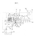
- FIG. 1 is a diagram illustrating an example of the overall configuration of a fuel supply system including a high-pressure fuel supply pump according to the present embodiment.
- FIG. 2 is a cross-sectional view of the high-pressure fuel pump main body in the present embodiment. In FIG. 2, the same symbols are used for components equivalent to those in FIG.
- a portion 101 surrounded by a broken line indicates a high-pressure fuel supply pump main body, and the mechanisms and components shown in the broken line indicate that they are integrated into the high-pressure fuel supply pump main body 101.
- Fuel is fed into the high-pressure fuel supply pump main body 101 from the fuel tank 110 via the feed pump 111, and pressurized fuel is sent from the high-pressure fuel supply pump main body 101 through the common rail 121 to the fuel injection device 122. It is done.
- the engine control unit 123 takes in the fuel pressure from the pressure sensor 124 and controls the feed pump 111, the electromagnetic coil 102 (solenoid) in the high-pressure fuel supply pump main body 101, and the fuel injection device 122 in order to optimize the pressure.
- the fuel in the fuel tank 110 is pumped up by the feed pump 111 based on the control signal S 1 from the engine control unit 123, pressurized to an appropriate feed pressure, and passed through the suction pipe 112 to the low pressure fuel of the high pressure fuel supply pump 101. It is sent to the suction port (suction joint) 103.
- the fuel that has passed through the low pressure fuel suction port 103 reaches the suction port 107 of the flow rate control valve 106 that constitutes the variable capacity mechanism via the pressure pulsation reduction mechanism 104 and the suction passage 105.
- the pressure pulsation reduction mechanism 104 communicates with an annular low-pressure fuel chamber 109 that changes the pressure in conjunction with a plunger 108 that reciprocates by an engine cam mechanism (not shown). The pulsation of the fuel pressure sucked into the suction port 107 is reduced.
- the fuel that has flowed into the suction port 107 of the flow control valve 106 passes through the suction valve 113 and flows into the pressurizing chamber 114.
- the valve position of the intake valve 113 is determined by controlling the electromagnetic coil 106 in the high-pressure fuel supply pump main body 101 based on the control signal S2 from the engine control unit 123.
- the reciprocating power is given to the plunger 108 by an engine cam mechanism (not shown).
- the reciprocating motion of the plunger 108 sucks fuel from the suction valve 113 in the lowering process of the plunger 108, pressurizes the sucked fuel in the lifting process of the plunger 108, and the pressure sensor 124 is attached via the discharge valve mechanism 115.
- Fuel is pumped to the common rail 121. Thereafter, based on the control signal S3 from the engine control unit 123, the fuel injection device 122 injects fuel into the engine.
- the discharge valve mechanism 115 provided at the outlet of the pressurizing chamber 114 includes a discharge valve sheet 115a, a discharge valve 115b that contacts and separates from the discharge valve sheet 115a, and a discharge valve spring that biases the discharge valve 115b toward the discharge valve sheet 115a. 115c or the like.
- the discharge valve 115b is opened. The pressurized fuel is pumped to the side.
- 113 is a suction valve
- 117 is a rod for controlling the position of the suction valve 113
- 442 is a movable portion
- 441 is fixed to the anchor portion 118 and is slid with the rod 117.
- the moving anchor sliding portion, 119 is a suction valve spring
- 125 is a biasing spring that biases the rod toward the suction valve 113
- 126 is an anchor portion biasing spring.
- the suction valve 113 is biased in the valve closing direction by the suction valve spring 119, and is biased in the valve opening direction by the rod biasing spring 125 via the rod 117.
- the movable portion 442 is biased in the valve closing direction by the anchor portion biasing spring 126.
- the valve position of the suction valve 113 is controlled by driving the rod 117 by the solenoid 102.
- a component formed integrally with the movable portion 442 and the anchor sliding portion 441 is referred to as an anchor portion 118.
- the high-pressure fuel supply pump 101 controls the solenoid 102 in the high-pressure fuel supply pump body 101 by the control signal S ⁇ b> 2 given to the flow control valve 106 by the engine control unit 123, and sends the pressure to the common rail 121 via the discharge valve mechanism 115.
- the fuel flow rate is discharged so that the desired fuel becomes the desired supply fuel.
- the pressurizing chamber 114 and the common rail 121 are communicated with each other by a relief valve 130.
- the relief valve 130 is a valve mechanism arranged in parallel with the discharge valve mechanism 115.
- the relief valve 130 opens and the fuel is returned to the pressurizing chamber 114 of the high-pressure fuel supply pump 101, so that the inside of the common rail 121. Prevents abnormal high pressure conditions.
- the relief valve 130 forms a high-pressure flow path 131 that connects the discharge passage 116 downstream of the discharge valve 115b in the high-pressure fuel supply pump main body 101 and the pressurizing chamber 114, and bypasses the discharge valve 115b here.
- the high-pressure channel 131 is provided with a relief valve 132 that restricts the flow of fuel in only one direction from the discharge channel 131 to the pressurizing chamber 114.
- the relief valve 132 is pressed against the relief valve seat 134 by a relief spring 133 that generates a pressing force, and the pressure difference between the inside of the pressurizing chamber 114 and the inside of the high-pressure channel 131 is determined by the relief spring 133. If it becomes above, it will set so that the relief valve 130 may leave
- the differential pressure between the discharge passage 131 and the pressurizing chamber 114 is greater than the opening pressure of the relief valve 132. Then, the relief valve 130 is opened, and the fuel having an abnormally high pressure is returned from the discharge passage 131 to the pressurizing chamber 114, and the high-pressure section piping such as the common rail 121 is protected.
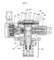
- FIG. 2 is a diagram showing a specific example of the high-pressure fuel supply pump main body 101 which is mechanically integrated.
- a plunger 108 that reciprocates (in this case, up and down) by an engine cam mechanism (not shown) in the central height direction shown in the figure is disposed in the cylinder 201, and in the cylinder 201 above the plunger 108.
- a pressurizing chamber 114 is formed.
- a mechanism on the flow control valve 106 side is arranged on the left side of the center of the figure, and a mechanism of relief 130 is arranged on the right side of the center of the figure.
- a low-pressure fuel inlet (not shown), a pressure pulsation reduction mechanism 202, a suction passage 203, and the like are arranged in the upper part of the figure as a fuel suction side mechanism.
- a plunger internal combustion engine side mechanism 204 is described in the lower center portion of FIG.
- the plunger internal combustion engine side mechanism 204 is a portion that is embedded and fixed in the internal combustion engine body as shown in FIG. Note that the low-pressure fuel inlet is not shown in the display cross section of FIG.
- the low-pressure fuel intake port can be displayed in a display section at a different angle, but since it is not directly related to the present invention, description and display are omitted.
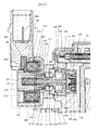
- FIG. 3 shows a state in which the attachment root (plunger internal combustion engine side mechanism) 204 is embedded and fixed in the internal combustion engine body.
- the attachment root portion 204 since the attachment root portion 204 is mainly described, description of other portions is omitted.
- the low-pressure fuel inlet 301 is located at the upper part of the fuel pump body, but the low-pressure fuel inlet 131 may be provided on the circumference around the cylinder 108.
- reference numeral 302 denotes a thick portion of the cylinder head of the internal combustion engine.
- the cylinder head 302 of the internal combustion engine is formed with an attachment root attachment hole 303 having a two-stage diameter in accordance with the shape of the attachment root 204.
- the attachment root portion 204 is airtightly fixed to the cylinder head 302 of the internal combustion engine.
- the high-pressure fuel supply pump is in close contact with the plane of the cylinder head 302 using a flange 304 provided in the pump body 1, and is fixed with at least two or more bolts 305.
- the mounting flange 304 is welded to the pump body 1 at the welded portion 306 by laser welding to form an annular fixed portion.
- an O-ring 307 is fitted into the pump body 1 for sealing between the cylinder head 302 and the pump body 1 to prevent engine oil from leaking to the outside.
- the flange 304 and the pump body 1 may be integrally formed.
- the plunger root portion 204 is provided with a tappet 310 at the lower end 308 of the plunger 108, which converts the rotational motion of the cam 309 attached to the camshaft of the internal combustion engine into vertical motion and transmits it to the plunger 108.
- the plunger 108 is pressure-bonded to the tappet 310 by a spring 312 via a retainer 311. Thereby, the plunger 108 is reciprocated up and down with the rotational movement of the cam 309.
- a plunger seal 314 held at the lower end of the inner periphery of the seal holder 313 is installed in a state where the plunger seal 314 is slidably in contact with the outer periphery of the plunger 108 at the lower portion of the cylinder 315 in the figure.
- the fuel can be sealed even when the plunger 108 slides to prevent the fuel from leaking to the outside.
- the high pressure fuel supply pump main body 101 has a bottomed cylindrical shape with an end (upper side in FIG. 2) formed so as to guide the reciprocating motion of the plunger 108 and form a pressurizing chamber 114 therein.
- a cylinder 201 is attached.
- an annular groove 206, an annular groove 207, and a pressurizing chamber are formed on the outer peripheral side so as to communicate with the pressurizing chamber 114 flow control valve 106 and a discharge valve mechanism 115 for discharging fuel from the pressurizing chamber 114 to the discharge passage.
- a plurality of communication holes communicating with 114 are provided.
- the cylinder 201 is fixed at the outer diameter by being joined to the high-pressure fuel supply pump main body 101 by press-fitting. It is sealed. Further, a small diameter portion 207 is provided on the outer diameter of the cylinder 201 on the pressure chamber 114 side. When the fuel in the pressurizing chamber 114 is pressurized, the cylinder 201 exerts a force on the low pressure fuel chamber 220 side. However, by providing the pump body 101 with the small diameter portion 230, the cylinder 201 is pulled out to the low pressure fuel chamber 208 side. To prevent that. By bringing the surfaces into contact with a plane in the axial direction, in addition to the sealing of the contact cylindrical surface of the high-pressure fuel supply pump main body 101 and the cylinder 201, a double seal function is also achieved.
- a damper cover 208 is fixed to the head of the high-pressure fuel supply pump main body 101.
- a suction joint (not shown) is provided on the low pressure fuel chamber side of the high pressure fuel supply pump main body 101 to form a low pressure fuel inlet (not shown).
- the fuel that has passed through the low-pressure fuel suction port passes through a filter (not shown) fixed inside the suction joint, and passes through the pressure pulsation reducing mechanism 202 and the low-pressure fuel flow path 203 to the suction port 209 of the flow control valve 106.
- the plunger 108 has a large diameter portion 210 and a small diameter portion 211, so that the volume of the annular low pressure fuel chamber 212 increases and decreases as the plunger 108 reciprocates.
- the increase / decrease in volume is communicated with the low pressure fuel chamber 220 through the fuel passage 320 (FIG. 3), so that when the plunger 108 is lowered, the annular low pressure fuel chamber 212 is moved to the low pressure fuel chamber 220, and when the plunger 108 is raised, the low pressure is reduced.
- a fuel flow is generated from the fuel chamber 220 to the annular low pressure fuel chamber 212.
- the flow rate of fuel into and out of the pump in the pump suction process or return process can be reduced, and the function of reducing pulsation is provided.
- the low pressure fuel chamber 220 is provided with a pressure pulsation reduction mechanism 202 that reduces the pressure pulsation generated in the high pressure fuel supply pump from spreading to the fuel pipe 130 (FIG. 1).
- a pressure pulsation reduction mechanism 202 that reduces the pressure pulsation generated in the high pressure fuel supply pump from spreading to the fuel pipe 130 (FIG. 1).
- the pressure pulsation reduction mechanism 202 is formed of a metal damper in which two corrugated disk-shaped metal plates are bonded together on the outer periphery thereof, and an inert gas such as argon is injected therein, and the pressure pulsation is generated by the metal damper. Absorption is reduced by expanding and contracting.
- Reference numeral 221 denotes a mounting bracket for fixing the metal damper to the high-pressure fuel supply pump main body 101.
- the discharge valve mechanism includes a discharge valve sheet 115a, a discharge valve 115b that contacts and separates from the discharge valve sheet 115a, a discharge valve spring 115c that biases the discharge valve 115b toward the discharge valve sheet 115a, a discharge valve 115b, and a discharge valve sheet 115a.
- the discharge valve holder 115d and the discharge valve holder 115d are joined by welding at a contact portion (not shown) to form an integral discharge valve mechanism 115.
- FIG. 4 shows the state in the suction process among the suction, return, and discharge processes in the pump operation
- FIGS. 5 and 6 show the state in the discharge process.
- the structure on the flow control valve 106 side is broadly described as a suction valve portion 4A mainly composed of the suction valve 113, and a solenoid mechanism portion 4B mainly composed of the rod 117, the movable portion and the solenoid 102.
- the suction valve The part A includes a suction valve 113, a suction valve seat 401, a suction valve stopper 402, a suction valve biasing spring 119, and a suction valve holder 403.
- the intake valve seat 401 is cylindrical, has a seat portion 405 in the axial direction on the inner peripheral side, and two or more intake passage portions 404 that are radially centered about the axis of the cylinder. 101 is held by press fitting.
- the suction valve holder 403 has claws in two or more directions radially, and the claw outer peripheral side is fitted and held coaxially on the inner peripheral side of the suction valve seat 401. Further, a suction stopper 402 having a cylindrical shape and having a collar shape at one end is press-fitted and held on the inner peripheral cylindrical surface of the suction valve holder 403.
- the suction valve urging spring 119 is disposed on the inner peripheral side of the suction valve stopper 402 in a small diameter part for stabilizing one end of the spring coaxially, and the suction valve 113 and the suction valve seat part 405 are suctioned.
- a suction valve biasing spring 119 is fitted to the valve guide portion 444 between the valve stoppers 402.
- the suction valve urging spring 119 is a compression coil spring and is installed so that the urging force acts in a direction in which the suction valve 113 is pressed against the suction valve seat portion 405. It is not limited to the compression coil spring, and any form may be used as long as an urging force can be obtained, and a leaf spring having an urging force integrated with the suction valve 113 may be used.
- the suction valve portion A By configuring the suction valve portion A in this way, in the pump suction process, the fuel that has passed through the suction passage 404 and entered the flow control valve passes between the suction valve 113 and the seat portion 405, The fuel passes through the fuel passage 445 provided on the outer peripheral side of the suction valve 113 and the outer diameter of the suction valve stopper 402, passes through the passage of the high-pressure fuel supply pump main body 101 and the cylinder, and flows the fuel into the pressurizing chamber. Further, in the pump discharge process, the intake valve 113 comes into contact with the intake valve seat portion 405 to seal the fuel, thereby fulfilling the function of a check valve that prevents the fuel from flowing back to the inlet side.
- the amount of movement 446 in the axial direction of the suction valve 113 is limited by the suction valve stopper 402. This is because if the amount of movement is too large, the reverse flow rate increases due to a response delay when the intake valve 113 is closed, and the performance as a pump decreases.
- the movement amount can be regulated by the shape and dimension of the suction valve seat 401, the suction valve 113, and the suction valve stopper 402 in the axial direction and the press-fitting position.
- the suction valve stopper 402 is provided with an annular protrusion so that the contact area with the suction valve stopper 402 is reduced when the suction valve 113 is open. This is because the intake valve 113 is easily separated from the intake valve stopper 402 during the transition from the open state to the closed state, that is, the valve closing response is improved.
- the pressure between the suction valve 113 and the suction valve stopper 402 decreases, A squeeze force acts in a direction that prevents movement, and the suction valve 113 is less likely to be separated from the suction valve stopper 402.
- the suction valve 113, the suction valve seat 401, and the suction valve stopper 402 repeatedly collide when operated, it is preferable to use a material obtained by heat-treating martensitic stainless steel having high strength, high hardness, and excellent corrosion resistance.
- a material obtained by heat-treating martensitic stainless steel having high strength, high hardness, and excellent corrosion resistance.
- an austenitic stainless material may be used in consideration of corrosion resistance.
- the solenoid mechanism B includes a rod 117 that is a movable part, a movable part, a guide part 410 that is a fixed part, an outer core 411, a fixed core 412, a rod biasing spring 125, an anchor part biasing spring 126, and a cover part 415. , Yoke 423 and solenoid 102.
- the rod 117 and the anchor 118 which are movable parts are configured as separate members.
- the rod 117 is slidably held in the axial direction on the inner peripheral side of the guide portion 410, and the inner peripheral side of the anchor sliding portion 441 of the movable portion is slidably held on the outer peripheral side of the rod 117. That is, both the rod 117 and the anchor portion 118 are configured to be slidable in the axial direction as long as they are geometrically restricted.
- the anchor sliding portion 441 is configured to come into contact with the flange portion 417a of the rod 117 at the end surface on the fixed core 412 side.
- the anchor portion 118 has one or more through holes 450 penetrating in the axial direction of the component in the anchor sliding portion 441 so that the anchor portion 118 moves smoothly and freely in the axial direction in the fuel. Limits are eliminated as much as possible.
- the through hole 450 is provided at the center of the rod 117, and a lateral groove fuel passage is provided on the suction valve 113 side of the guide portion 410 so as to be substantially parallel to the suction passage portion 404, so that the fixed core 412 of the anchor portion 118 is provided.
- the space on the side and the space 413 upstream of the suction valve seat 401 may be communicated with each other. As a result, the space on the fixed core 412 side of the anchor portion 118 can be communicated without providing the fuel passage 414 of the guide portion 410, and the processing cost of the guide portion 410 can be suppressed.
- the guide portion 410 is inserted in the radial direction on the inner peripheral side of the hole into which the intake valve 113 of the high-pressure fuel supply pump main body 101 is inserted, and is axially abutted against one end portion of the intake valve seat 405.
- the high-pressure fuel supply pump main body 101 is arranged to be sandwiched between the outer core 411 that is welded and fixed to the high-pressure fuel supply pump main body 101 and the high-pressure fuel supply pump main body 101.
- the guide portion 410 is provided with a fuel passage 414 that penetrates in the axial direction, and the pressure of the fuel chamber on the anchor portion 118 side is adjusted so that the anchor portion 118 can move freely and smoothly. It is configured not to disturb the movement of
- the outer core 411 has a thin cylindrical shape on the side opposite to the portion to be welded to the high-pressure fuel supply pump main body 101, and is fixed by joining and fixing the fixed core 412 on the inner peripheral side thereof.
- a rod urging spring 40 is disposed on the inner peripheral side of the fixed core 412 with a narrow diameter portion as a guide, the rod 117 comes into contact with the suction valve 113, and the suction valve 113 is separated from the suction valve seat 401, that is, suction. An urging force is applied in the valve opening direction of the valve 113.
- the anchor portion biasing spring 126 is disposed so as to apply a biasing force to the anchor portion 118 in the direction of the rod collar portion 117a while inserting the one end into a cylindrical central bearing portion 452 provided on the center side of the guide portion 410 and maintaining the same axis. It is said.
- the movement amount 470 of the anchor part 118 is set larger than the movement amount 446 of the suction valve 113.
- the discharge flow rate can be secured.
- the excluded volume accompanying the movement of the anchor portion 118 when the valve is closed flows between the anchor portion 118 and the fixed core 812, so that the pressure between the anchor portion 118 and the fixed core 812 increases.
- a fluid force so-called squeeze force
- the squeeze force is generally proportional to the cube of the gap between the anchor portion 118 and the fixed core 812, the smaller the gap, the greater the influence.
- the rod 117 and the guide portion 410 slide relative to each other, and the rod 117 repeatedly collides with the suction valve 113, so that a heat-treated martensitic stainless steel is used in consideration of hardness and corrosion resistance.
- the anchor portion 118 and the fixed core 412 are preferably made of ferritic magnetic stainless steel to form a magnetic circuit, and the rod biasing spring 125 and the anchor portion biasing spring 126 are preferably made of austenitic stainless steel in consideration of corrosion resistance.
- the intake valve portion A and the solenoid mechanism portion B are configured by organically arranging three springs.
- the suction valve biasing spring 119 configured in the suction valve section A, the rod biasing spring 125 and the anchor section biasing spring 126 configured in the solenoid mechanism section B correspond to this.
- any spring uses a coil spring, but any spring can be used as long as it can obtain an urging force.
- the solenoid part includes a cover part 415, a yoke 423, a solenoid 102, a bobbin 453, a terminal 454, and a connector 455.
- a solenoid 102 in which a copper wire is wound around a bobbin 453 is disposed so as to be surrounded by a cover portion 415 and a yoke 423, and is molded and fixed integrally with a connector which is a resin member.
- the respective ends of the two terminals 454 are connected to both ends of the copper wire of the solenoid 102 so as to be energized.
- the terminal 454 is molded integrally with the connector 455 so that the remaining end can be connected to the engine control unit side.
- a seal ring 418 is provided on the solenoid 102 side in the radial direction of the outer diameter of the fixed core 412.
- the seal ring 418 is fixed by being press-fit to the outer diameter portion 417 of the fixed core 412 and the outer diameter portion 420 of the outer core 411, and the vicinity of the press-fit fixing portion is welded to seal the fuel.
- the seal ring 418 is provided on the outer diameter side facing the suction surface 421 of the fixed core 412 in the radial direction. Further, the small diameter portion 440 of the yoke 423 is press-fitted into the outer core 411 and fixed. At that time, the inner diameter side of the cover portion 415 is configured to come into contact with the fixed core 39 or close to it with a slight clearance.
- Both the cover part 415 and the yoke 423 are made of a magnetic stainless steel material for constituting a magnetic circuit and considering corrosion resistance, and the bobbin 453 and the connector 454 are made of high-strength heat-resistant resin in consideration of strength characteristics and heat resistance characteristics.
- the solenoid 102 is made of copper, and the terminal 454 is made of brass plated with metal.
- a magnetic circuit is formed by the anchor portion 118, the fixed core 412, the cover portion 415, the yoke 423, and the outer core 411 as shown by a broken line 422 in FIG.
- a current is supplied to 102, a magnetic attractive force is generated between the fixed core 412 and the anchor portion 118, and a force that pulls the anchor portion 118 toward the fixed core 412 is generated.
- the seal ring 418 By configuring the seal ring 418 to use austenitic stainless steel, the magnetic flux can easily pass between the fixed core 412 and the anchor portion 118, and the magnetic attractive force can be improved.
- the seal ring 418 is integrally formed with the outer core 411, the magnetic flux flowing on the outer core 411 side can be reduced by making the portion located on the outer diameter in the radial direction of the suction surface 421 as thin as possible. As a result, the magnetic flux passing between the fixed core 412 and the anchor portion 118 increases, and the magnetic attractive force can be improved.
- the anchor part 118 that is a movable part is attracted to the fixed core together with the rod 117, and the anchor part 118 is fixed to the fixed core 412. The anchor part continues to move until it comes into contact with.
- the above configuration of the high pressure fuel supply pump according to the present invention operates as follows in each step of suction, return, and discharge in the pump operation.
- the inhalation process will be explained.
- the plunger 108 moves in the direction of the cam 309 (the plunger 108 is lowered) by the rotation of the cam 309 in FIG. That is, the position of the plunger 108 has moved from the top dead center to the bottom dead center.
- the volume of the pressurizing chamber 114 increases and the fuel pressure in the pressurizing chamber 114 decreases.
- the plunger 108 moves in the upward direction by the rotation of the cam 309 in FIG. That is, the position of the plunger 108 starts to move from the bottom dead center toward the top dead center.
- the volume of the pressurizing chamber 114 decreases with the compressing motion after the suction in the plunger 108.
- the fuel once sucked into the pressurizing chamber 114 is again sucked through the intake valve 113 in the valve open state. Since the pressure is returned to the passage 404, the pressure in the pressurizing chamber 114 does not increase. This process is called a return process.
- FIG. 5 shows the positional relationship of each part on the flow rate control valve 106 side when the magnetic attractive force is applied, and this will be described with reference to FIG.
- a current is applied to the solenoid 102
- magnetic flux passes between the fixed core 412 and the anchor portion 118
- a magnetic attractive force is generated in the anchor portion 118
- the magnetic attraction attracts the anchor portion 118 to the fixed core 412 side. Force is generated.
- the compression process of the plunger 108 (the ascending process from the lower start point to the upper start point) includes a return process and a discharge process.
- the amount of high-pressure fuel that is discharged can be controlled by controlling the energization timing of the solenoid 102 of the flow control valve 106. If the timing of energizing the solenoid 102 is advanced, the ratio of the return process in the compression process is small and the ratio of the discharge process is large. That is, the amount of fuel returned to the suction passage 404 is small and the amount of fuel discharged at high pressure is large. On the other hand, if the timing of energization is delayed, the ratio of the return process in the compression process is large and the ratio of the discharge process is small.
- the amount of fuel returned to the suction passage 404 is large, and the amount of fuel discharged at high pressure is small.
- the amount of fuel discharged at high pressure can be controlled to an amount required by the internal combustion engine.
- FIG. 6 shows the positional relationship of each part on the flow rate control valve 106 side in the discharge process.
- a diagram of a non-energized state in which the energization of the solenoid 102 is released when the suction valve 113 is closed (valve closed) after the pump chamber pressure has increased sufficiently is shown.
- a system is in place to effectively generate and act the next magnetic attractive force. This structure is characterized by the establishment of this system.
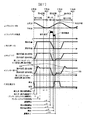
- the suction process is a period in which the position of the plunger 108 is from the top dead center to the bottom dead center, and the position of the plunger 108 is dead in the period of the return process and the discharge process. This is the period from point to top dead center.
- the suction current is supplied to the solenoid 102 during the return process, and the process proceeds to the discharge process while the holding current is subsequently supplied.
- C) the position of the suction valve 113, d) the position of the rod 117, and e) the position of the anchor portion 118 are changed in accordance with b) the generation of the magnetic attraction force due to the current supply to the solenoid 102.
- the original position is restored.
- the suction valve 113 collides with the suction valve stopper 402, and the suction valve 113 stops at that position.
- the rod 117 also stops at a position where the tip comes into contact with the suction valve 113 (the plunger rod opening position in FIG. 7).
- the anchor portion 118 initially moves in the opening direction of the suction valve 113 at the same speed as the rod 117, but continues to move with inertial force even after the time t2 when the rod 117 comes into contact with the suction valve 113 and stops. .
- the portion indicated by OA in FIG. 7 is this overshoot region.
- the anchor portion biasing spring 126 overcomes the inertial force, the anchor portion 118 moves again in the direction approaching the fixed core 412, and contacts the rod collar portion 417a in a form in which the anchor portion 118 is pressed (see FIG. 7 at the anchor portion valve opening position).
- the stop time of the anchor part 118 due to re-contact between the rod 117 and the anchor part 118 is indicated by t3.
- the state which shows each position of the anchor part 118, the rod 117, and the suction valve 113 in the stable state after the stop time t3 in the time t4 is shown by FIG.
- the rod 117 and the anchor portion 118 are completely separated at the portion indicated by OA.
- the rod 117 and the anchor portion 118 may be in contact with each other.
- the load acting on the contact portion between the rod collar portion 417a and the anchor portion 118 decreases after the movement of the anchor rod 117 stops, and when it becomes zero, the anchor portion 118 starts to separate from the anchor rod 117.
- the setting force of the anchor portion biasing spring 126 that leaves a slight load may be used.
- the magnitude of the abnormal noise is due to the magnitude of the energy at the time of the collision
- the energy that collides with the suction valve stopper 32 is the suction. It is generated only by the mass of the valve 113 and the mass of the anchor rod 117. That is, since the mass of the anchor portion 118 does not contribute to the collision energy, the problem of abnormal noise can be reduced by configuring the rod 117 and the anchor portion 118 separately.
- the movable portion 442 may be made of ferritic stainless steel having good magnetic properties, and the sliding portion 441 may be made of austenitic stainless steel having high hardness.
- SUS420 is preferably used for the sliding portion 441 because the hardness can be secured by heat treatment of quenching.
- the anchor portion biasing spring 126 in order for the anchor portion 118 to continue the movement in the valve opening direction by the inertia force, the surface of the anchor portion 118 that faces the fixed core 412, and the fixed core 412 The distance from the suction surface 421 increases (the OA portion in FIG. 7).
- the solenoid 102 in order to make a transition from the return process, which is a subsequent process, as the operation time, the magnetic resistance between the fixed core 421 and the anchor portion 118 increases, and the necessary magnetic force There arises a problem that the suction force cannot be obtained. If the required magnetic attractive force cannot be obtained, the maximum flow rate of fuel discharged from the high-pressure fuel supply pump may be reduced.
- the anchor portion biasing spring 126 has an important function for preventing the flow rate from decreasing.
- the plunger 108 is further lowered to reach the bottom dead center (time t5). During this time, the fuel continues to flow into the pressurizing chamber 114, and this process is an intake process. The plunger 108 lowered to the bottom dead center enters the ascending process and proceeds to the returning process.
- the suction valve 113 remains stopped in the open state by the force f1 in the direction in which the valve opens, and the direction of the fluid passing through the suction valve 113 is reversed. That is, in the suction process, fuel has flowed from the passage of the suction valve seat 405 into the pressurization chamber 114, but at the time of the rising process, the fuel is returned from the pressurization chamber 114 toward the passage of the suction valve seat 405. It is. This process is a return process.
- a current is supplied to the solenoid 102 to create a transition state from the return process to the discharge process.
- t ⁇ b> 7 represents the closing motion start time of the suction valve 113
- t ⁇ b> 8 represents the holding current start time
- t ⁇ b> 9 represents the closing time of the suction valve 113
- t ⁇ b> 10 represents the energization end time of the solenoid 102.
- the rod 117 that is in contact with the collar portion 417a in the axial direction also moves in the valve closing direction, and the suction valve 113 receives the force of the suction valve biasing spring 126 and the flow.
- the valve closing starts (time t9) due to a decrease in the physical strength, mainly the static pressure due to the flow velocity passing through the seat portion from the pressurizing chamber side.
- the anchor portion biasing spring 126 is provided in the present invention.
- the suction valve 113 is kept open even at the discharge timing, so that the discharge process cannot be started, that is, a necessary discharge amount cannot be obtained.
- the anchor portion biasing spring 126 has an important function for preventing an abnormal noise problem that may occur in the suction process and for preventing a problem that the discharge process cannot be started.
- the anchor portion 118 moves in the direction of the fixed core 412 by the anchor rod 117 being separated from the intake valve 113 after the intake valve 113 is closed, and collides with the fixed core 412 and stops.
- the rod 35 continues to move with the inertial force even after the anchor portion 36 stops, but the rod biasing spring 126 overcomes the inertial force and is pushed back so that the collar portion 417a can return to a position where it comes into contact with the anchor portion 118.
- the anchor rod 117 and the anchor part 118 are configured separately, the energy that collides with the fixed core 412 is the anchor part 118. Only the mass of contributes. That is, since the mass of the rod 117 does not contribute to the collision energy, the problem of abnormal noise is reduced by configuring the rod 117 and the anchor portion 118 separately.
- the magnetic resistance between the anchor part 118 and the fixed core 412 is small due to the contact, so that a sufficient magnetic attractive force is generated and the contact is maintained. Therefore, a small current value (holding current) can be obtained.
- the pushed fluid passes through the outer periphery of the anchor portion 118 and flows toward the guide portion, but the flow rate increases because the passage on the outer periphery side of the anchor portion is narrow, that is, cavitation occurs due to a rapid decrease in static pressure.
- cavitation erosion may occur in the seal ring 418.
- a thin wall portion is formed in the outer core 411 in order to propose a leakage magnetic flux that passes through other than the suction surface 421 by using the seal ring 418. There is no need, and there is an effect of suppressing cavitation.
- one or more axial through holes 450 are provided on the center side of the sliding portion 441 constituting the anchor portion 118.
- the through hole 450 is provided on the end surface of the movable portion 442 on the fixed core 412 side, the attractive area is reduced and the magnetic attractive force is reduced.
- the movable portion 442 and the sliding portion 441 as separate bodies, it is possible to provide the through hole 450 at a position downstream of the movable portion 442 that is not the main path of the magnetic circuit. Ensuring both.
- the radial position of the through hole 450 is preferably provided on the outer diameter side of the inner diameter of the fixed core 412 or the inner diameter of the end surface of the movable portion 442 on the fixed core 412 side.
- the anchor portion 118 and the rod 117 are configured separately, even when a force for closing the suction valve 113 is applied to the rod 117, only the rod 117 is pushed out to the fixed core 412 side, and the anchor portion 118 is left behind. Then, the movement to the fixed core 412 side is performed with the force of only the normal magnetic attractive force. That is, there is no sudden space reduction, and the occurrence of erosion problems can be prevented.
- the anchor portion 118 and the rod 117 are formed separately, and there are problems that the desired magnetic attraction force cannot be obtained, noise, and function deterioration.
- the anchor portion biasing spring 126 is installed. This makes it possible to eliminate this harmful effect.
- the magnetic attractive force does not act on the anchor portion 118, and the anchor portion 118 and the rod 117 move away from the fixed core 412 by the resultant force of the rod biasing spring 125 and the anchor portion biasing spring 126.
- the rod 117 stops at a position where it collides with the closed suction valve 113. That is, the amount of movement of the rod 117 at this time is a value obtained by subtracting 446 from 470 in FIG.
- the magnetic attraction force acting on the anchor portion 118 simultaneously moves at a timing when the force in the valve opening direction acting on the anchor portion 118 and the rod 117 falls below.
- the anchor portion 118 continues to move toward the suction valve 113 by inertial force ( The state of OB in FIG. 7).
- the anchor portion biasing spring 126 overcomes the inertial force and applies a biasing force in the direction of the fixed core 412 to the anchor portion 118, the anchor portion 118 is in contact with the collar portion 417a of the rod 117 (the state of FIG. 6). Can be stopped.
- the fuel led to the low pressure fuel inlet (not shown) is pressurized to a high pressure by the reciprocating movement of the plunger 108 in the pressurizing chamber 114 of the high pressure fuel supply pump main body 101 as the pump main body,
- a high-pressure fuel supply pump suitable for being pumped from the fuel discharge port (not shown) to the common rail 121 can be provided.
- the suction valve 113 needs to be closed quickly, it is preferable to set the spring force of the suction valve spring 119 as large as possible and set the spring force of the anchor portion biasing spring 41 small. As a result, it is possible to prevent the flow efficiency from deteriorating due to the delay in closing the intake valve 113.
- the anchor portion 118 is formed of a movable portion 442 that forms a magnetic path and a sliding portion 441 that slides with the rod 117.
- the sliding portion 441 is subjected to a heat treatment such as a surface treatment such as a plating treatment or a quenching treatment to increase the hardness.
- a heat treatment such as a surface treatment such as a plating treatment or a quenching treatment to increase the hardness.
- plating treatment a method is conceivable in which only the sliding portion 441 is treated by masking a portion that does not require treatment.
- quenching treatment induction quenching, laser quenching, or partial carburizing quenching in which a carburizing agent is applied to a portion that does not require treatment can be considered.
- the flow control valve 106 of the present invention is not limited to the high-pressure fuel pump main body 101, and even when applied to a device for controlling the flow rate of an injector or the like, an effect of improving responsiveness can be obtained.
- the axial position of the passage 460 may be configured closer to the fixed core than the suction passage 404.
- the passage 460 and the suction passage 404 are configured such that the cross sections of the fuel passages overlap each other. With this configuration, the fuel coming from the suction passage 404 is secured without enlarging the outer diameter of the high-pressure pump body while ensuring a space for containing the suction valve 113, the suction valve seat 401, and the suction valve stopper 402 in the high-pressure pump body. Since it flows in an oblique direction with respect to the passage 460, there is a merit that the passage sectional area of the fuel can be secured.
- the sliding surface of the guide portion 452 with the anchor rod 117 may be extended to a position facing the passage 460 in the radial direction. .
- the strength against abrasion of the sliding portion due to sliding can be secured, and the inclination of the anchor portion 118 can be suppressed.
- the gap between the outer diameter of the anchor portion 118 and the inner diameter of the outer core 411 can be designed to be small, so that the magnetic resistance is reduced and the magnetic attractive force can be improved.
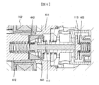
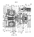
- FIG. 8 is an enlarged view of the flow control valve 106 in the second embodiment.
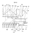
- FIG. 9 is an enlarged view of the cover portion 815, the fixed core 812, and the yoke 423, which are components of the magnetic circuit indicated by the enlarged portion 834 in FIG.
- the magnetic flux lines generated in the magnetic circuit are indicated by dotted lines.
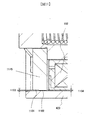
- FIG. 10 is an enlarged view of the enlarged portion 886 including the cover portion 815, the fixed core 812, the anchor portion 818, and the outer core 811 of FIG.
- the fixed core 812 is provided with an enlarged portion 830 in which the outer diameter increases toward the outer peripheral side of the solenoid 102 by contacting the cover portion 815 in the axial direction, and a small diameter portion 831 in which the outer diameter decreases.
- the cover portion 815 has a narrow-diameter portion 831 that is an end surface on the outer peripheral side of the fixed core 812 and an inner peripheral-side facing surface 835 that opposes the radial direction.
- the movable portion 442 and the sliding portion 441 in the first embodiment are integrally formed in the second embodiment and are referred to as an anchor portion 418.
- the fixed core 812 is provided with a small-diameter portion 831 on the outside in the axial direction, that is, on the side opposite to the anchor portion 118. Further, a fixing pin 832 is fixed to the narrow diameter portion 831, and the cover portion 815 is pressed so as to come into contact with the outer diameter enlarged portion 830, thereby restricting the axial movement of the cover portion 815.
- a seal ring 818 is provided on the suction valve 113 side facing the enlarged portion 830 in the axial direction.
- the outer diameter of the enlarged portion 830 of the fixed core 812 is configured to be larger than the inner diameter of the seal ring 818.
- the seal ring 818 is press-fitted and fixed to the outer diameter portion 419 of the fixed core 412 and the outer diameter portion 420 of the outer core 411, and is joined by welding, for example, to seal the fuel.
- the seal ring 818 is provided at a position facing the suction surface 421 of the fixed core 412 and the movable core 118 in the radial direction, blocks magnetic flow other than between the movable core 117 and the fixed core 812, and reduces leakage magnetic flux. .
- the magnetic flux flowing through the fixed core 812 and the movable core 118 increases, and the magnetic attractive force can be improved.
- the guide portion 452 and the suction valve seat 401 in the first embodiment are integrally formed, and a member constituted by the guide portion 452 and the suction valve seat 401 is referred to as a guide portion 852.
- the contact between the cover portion 815 and the enlarged portion 830 eliminates the magnetic gap between the cover portion 815 and the fixed core 812, thereby reducing the magnetic resistance.
- the magnetic attractive force can be increased, and the response of the anchor portion 418 is improved, so that the response of the intake valve 813 is also improved.
- the magnetic flux that can be generated in the magnetic circuit increases as the magnetic resistance decreases, and the magnetic flux that passes between the anchor portion 818 and the fixed core 812 also relatively increases.
- the magnetoresistance R is expressed by the following equation (3), where ⁇ is the permeability of the magnetic material constituting the magnetic circuit and S is the cross-sectional area of the cross section through which the magnetic flux passes. Is required.
- the magnetic gap between the cover portion 815 and the fixed core 812 can be reduced by bringing the cover portion 815 and the fixed core 812 into contact with each other in the axial direction, the magnetic permeability between the fixed core 812 and the cover portion 815 is reduced to a vacuum.
- the magnetic permeability of the magnetic material that constitutes the cover portion 815 and the fixed core 812 is determined from the magnetic permeability. As a result, the magnetic permeability can be increased, the magnetic resistance can be reduced, and the magnetic attractive force can be improved.
- the gap 842 between the outer diameter of the cover portion 815 and the inner diameter of the yoke 423 may be configured to be smaller than the gap 840 between the inner diameter of the cover portion 815 and the narrow diameter portion 831 of the fixed core 812. Since the magnetic flux tends to flow through a portion having a small magnetic resistance, the magnetic flux flowing from the fixed core 812 to the cover portion 815 is unlikely to flow between the cover portion 815 and the small diameter portion 831, and the fixed core 812 and the cover portion It tends to flow to the contact surface 833 with 815. In addition, since the main path of magnetic flux is between the cover portion 815 and the yoke 423, a large amount of magnetic flux generated in the magnetic circuit passes. Therefore, by configuring the magnetic gap between the cover portion 815 through which a lot of magnetic flux passes and the yoke 423 to be small, the magnetic resistance can be reduced and the magnetic attractive force can be improved.
- the load at the time of press-fitting acts on the seal ring 418, so the welded portion of the seal ring 418 and the seal ring 418 may be deformed by receiving the load at the time of press-fitting is there.
- stress is likely to act on the welded portion between the seal ring 418 and the fixed core 812 and the welded portion between the seal ring 418 and the inner core 811.
- the cover portion 815 generates a pressing force by the fixing pin 833 so that the cover portion 815 is restricted in the axial direction only by the outer diameter enlarged portion 830 of the fixed core 812.
- a large load at the time of press-fitting does not act on the welded portion, and the magnetic attraction force generated when the seal ring 418 is deformed or deformed by receiving the load and the moving amount of the anchor portion 118 is changed suppresses variations. effective.
- the material of the fixed core 812 and the anchor portion 418 may be a material having a magnetic property, particularly a high saturation magnetic flux density.
- the transmission of the fixed core 812 and the anchor portion 418 is obtained from the equation (3). Since the magnetic permeability ⁇ increases, the magnetic resistance decreases and the magnetic attractive force can be improved. Further, the magnetic attraction force acting on the anchor portion 418 is expressed by Equation (4) in a static state where there is no change in current, and the magnetic flux density B on the attraction surface of the anchor portion 418 and the anchor portion 418 are fixed. The attraction area S determined by the area facing the core 812 and the vacuum permeability ⁇ 0 are obtained. Therefore, by using a material having the highest saturation magnetic flux density for the fixed core 812 and the anchor portion 418, the magnetic attractive force can be improved and the responsiveness when the valve is closed can be improved.
- the location where the main magnetic flux generated in the magnetic circuit passes through the air (in the fuel) is a surface facing the anchor portion 418 in the fixed core 812, and a surface facing the fixed core 812 in the movable portion 418. It becomes the side surface 870 which opposes the outer core 811 in radial direction.
- the outer core 811 has a cross-sectional integral of the side surface 870, and the area of the surface facing the magnetic flux when the magnetic flux passes through the air is larger, so the anchor portion 418 is closer to the anchor portion 418 than the fixed core 812.
- a material having high magnetic properties may be used.
- the anchor rod 817 may be made of a material having lower magnetic characteristics than the anchor portion 818. Since the anchor rod 817 collides with the anchor portion 818 and the suction valve 813, the mechanical strength of the material, in particular, the hardness is required to be high. Therefore, martensitic stainless steel such as SUS420 may be used. In addition, SUS420 has a property that the hardness is increased by quenching and the magnetism is decreased by heat treatment. Therefore, SUS420 used for the guide portion 817 can be both hardened and reduced in magnetism by quenching. By reducing the magnetic characteristics of the anchor rod 817, the magnetic flux leaking from the fixed core 812 to the anchor rod 817 side can be reduced, and the magnetic attractive force can be improved.
- a material with good magnetic properties may be expensive. Therefore, by using a material with inferior magnetic properties for the cover portion 815, the yoke 423, and the outer core 811 compared to the fixed core 812 and the anchor portion 418, The cost of the flow control valve 106 can be reduced.
- the outer core 811 it is preferable to use a material having better magnetic properties for the outer core 811 than the cover portion 815 and the yoke 423. Since the magnetic flux flowing from the side surface 870 of the anchor portion 418 passes through the outer core 811, the magnetic resistance can be reduced by improving the magnetic characteristics and facilitating the passage of the magnetic flux. As a result, the magnetic attractive force is increased and the responsiveness can be improved.
- the anchor portion 418 is provided with a step 871 so that the step 871 is in contact with the end surface of the anchor rod 817 on the suction valve 813 side.
- the axial position of the end surface 872 on the fixed core 812 side of the anchor rod 817 is preferably on the intake valve 813 side than the end surface on the anchor portion 418 side of the fixed core 812.
- the axial position of the end surface 872 of the anchor rod 817 is closer to the cover portion 815 than the end surface on the anchor portion 418 side of the fixed core 812, the distance between the fixed core 812 and the end surface 872 becomes smaller, and the anchor rod 817 side In some cases, magnetic flux leaks to reduce the magnetic attractive force, resulting in slow response. Therefore, according to the configuration of the second embodiment of the present invention, since the magnetic flux that does not pass between the anchor portion 418 and the fixed core 812 and leaks to the anchor rod 817 can be reduced, the responsiveness can be improved.
- a pedestal surface 878 of the anchor portion biasing spring 126 whose inner diameter is reduced is provided on the end surface of the anchor portion 418 on the suction valve 813 side, and has a function of guiding the anchor portion biasing spring 126 in the radial direction.
- the axial position of the end surface on the intake valve 813 side of the anchor portion 418 is configured to be closer to the intake valve 813 side than the end surface on the fixed core 812 side of the guide portion 852.
- the material length can be shortened, and the material cost can be suppressed.
- the inner diameter of the outer core 811 has a function of guiding the anchor portion biasing spring 126 in the radial direction
- the outer diameter of the anchor portion biasing spring 126 is increased
- the anchor portion 418 has an anchor portion on the downstream end surface.
- a base for the biasing spring 126 may be configured. In the case of this configuration, since the anchor portion biasing spring 126 and the fuel passage 873 do not overlap in the radial direction, a large cross-sectional area of the fuel passage 873 can be secured. As a result, cavitation caused by an increase in pressure on the upper portion of the anchor portion 418 can be suppressed by the excluded volume accompanying the movement of the anchor portion 418.
- the configuration of the guide portion 852 will be described.
- the guide portion 852 has a function of sliding with the anchor rod 817 and a function of sealing fuel with the intake valve 813. Further, at least two fuel passages 881 are provided on the circumference of the guide portion 852, and the guide portion 852 has a function of causing the excluded volume accompanying the movement of the anchor portion 418 to flow downstream.
- the fixed core 812 side end surface of the guide portion 852 is provided with a pedestal surface of the anchor portion biasing spring 826 and has a guide portion 882 that guides the anchor portion biasing spring 826 with an outer diameter.
- the guide portion 882 By providing the guide portion 882, the inclination of the anchor portion biasing spring 826 can be suppressed. As a result, the moment with respect to the axial direction acting on the anchor portion 418 can be reduced, and the inclination of the anchor portion 418 can be suppressed.
- the anchor portion 418 is inclined, the magnetic resistance of the anchor side gap may be nonuniform in the circumferential direction with respect to the axis, and the magnetic attractive force may be reduced. With the configuration of this embodiment, the inclination of the anchor portion 418 can be suppressed, and the magnetic attractive force is increased, so that the responsiveness can be improved.
- the moving amount 446 of the suction valve 813 is preferably smaller than the moving amount 884 of the anchor portion 818, and the gap 885 between the anchor portion 818 and the guide portion 882 is preferably set smaller than the moving amount of the anchor portion 818.
- the end surface of the anchor portion 818 that faces the guide portion 882 and the surface of the guide portion 818 that faces the anchor portion 818 may be substantially flat.
- the squeeze force generally increases in proportion to the cube of the gap 885, the squeeze force increases as the anchor portion 818 approaches the guide portion 882, and the effect of decelerating the anchor portion 818 is enhanced.
- the gap 885 can be set small, so that the guide portion 882 can be extended to the anchor portion 818 side, and the effect that the sliding length between the anchor rod 817 and the guide portion 882 can be increased is obtained. .
- the effect of increasing the sliding length is as described above.
- the anchor portion 418 is provided with a fuel passage 872 for communicating the upstream and downstream of the anchor portion 418. Since the effect of providing the fuel passage 872 overlaps with that of the first embodiment, detailed description thereof is omitted.
- Two or more fuel passages 872 may be provided in a position opposite to the inner diameter of the fixed core 812 in the axial direction, and may be provided in a circumferential shape with respect to the shaft.
- the radial cross-sectional area between the outer diameter of the anchor portion 118 and the inner diameter of the outer core 811 (side gap) may be designed to be larger than the total cross-sectional area of the fuel passage 872.
- the flow rate associated with the excluded volume of the anchor portion 418 flows separately into the fuel passage 872 and the side gap, but when the gap between the anchor portion 418 and the fixed core 812 becomes small, the space in the space on the fixed core 418 side of the anchor portion 418 becomes smaller.
- the flow resistance increases, and it becomes difficult for the fuel to flow to the inner diameter side, that is, the fuel passage 872 side. Therefore, by making the cross-sectional area of the side gap larger than the total cross-sectional area of the fuel passage 872, the fuel accompanying the excluded volume can be efficiently flowed to the downstream side, and cavitation caused by a sudden pressure change is suppressed. There is an effect that can be done.
- FIG. 9 is a diagram showing magnetic flux lines when a magnetic attractive force is generated in the anchor portion 118 in the enlarged portion 834 of the flow control valve in FIG. 8 in FIG.
- the same symbols are used for parts equivalent to those in FIG.
- the magnetic flux lines passing through the fixed core 812, the cover portion 815, and the yoke 423 are indicated by dotted lines.
- the axial thickness of the cover portion 815 may be configured to be thicker than the radial thickness of the yoke 423.
- the magnetic path cross-sectional area is larger on the outer diameter side farther from the central axis 850 than on the inner diameter side near the central axis 850 of the solenoid 102. Therefore, by making the axial thickness of the cover portion 815 geometrically smaller in cross-sectional area than the cover portion 815 larger than the radial thickness of the yoke 423, the magnetic path cross-sectional area can be secured and the magnetoresistance Can be reduced.
- the magnetic attractive force can be increased, the responsiveness is improved and the controllability of the flow rate is improved.
- the magnetic flux does not easily pass through the gap portion, so that the magnetic flux flowing from the cover portion 815 to the yoke 423 as shown by the dotted line in FIG. Expands in the axial direction at the gap.
- the magnetic flux 903 passing through the vicinity of the opposite end surface 902 of the cover portion 815 facing the fixed core 812 cannot pass through the gap between the cover portion 815 and the yoke 423 as shown in the enlarged portion 901, and is in the air. May leak.
- the thickness of the cover portion 815 in the axial direction larger than the thickness of the yoke 423 in the radial direction, the leakage magnetic flux passing through the air of the enlarged portion 901 can be reduced, and the magnetic attractive force can be improved.
- the gap 840 between the inner peripheral facing surface 835 facing the small diameter portion 831 of the fixed core 812 of the cover portion 815 and the outer peripheral side of the small diameter portion of the fixed core 812 is formed in a range of approximately 12 ⁇ m to 100 ⁇ m. Good.
- the inner diameter or outer diameter of the cover portion 815 It is preferable to provide a gap in either the inner diameter or the outer diameter of the cover portion 815 so that the radial position can be defined on either one.
- the outer portion of the cover portion 815 is arranged so that the gap between the outer diameter of the cover portion 815 and the inner diameter of the yoke 423 can be reduced.
- the diameter and the inner diameter of the yoke 423 may be fitted with a clearance or light press-fitting.
- the gap 840 is preferably provided with a gap in the range of about 12 ⁇ m to 100 ⁇ m larger than 0 so that the inner diameter of the cover portion 815 and the small diameter portion 831 of the fixed core 812 do not contact each other.
- the radial position of the cover portion 815 is defined by the outer diameter of the cover portion 815 and the inner diameter of the yoke 423, the coaxial of the cover portion 815, the inner diameter of the yoke 423, and the coaxial of the stator 812 so as to ensure a gap 840. It is necessary to decide in consideration of the dimensional tolerance.
- the coaxial of the cover portion 815 is 0.01 mm
- the inner diameter of the yoke 423 is ⁇ 0.01 mm
- the coaxial of the stator 812 is 0.02
- each dimension The mean square of 0.02 mm is necessary, and the gap 840 on one side needs to be 0.012 mm or more.
- the maximum dimension tolerance is 0.05 mm for the cover 815
- the inner diameter of the yoke 423 is 0.1 mm
- the stator 812 is 0.05
- the sum of the dimensions is 0.2 mm.
- the gap 840 on one side needs to be 0.1 mm or more.
- the gap 840 is provided with a gap in the range of about 12 ⁇ m to 100 ⁇ m, and the gap 840 between the inner diameter of the cover portion 815 and the outer diameter of the narrow diameter portion 831 is minimized while defining the radial position of the cover portion 815.
- This makes it possible to achieve both improvement in magnetic attraction force.
- the relief 904 is not provided in the narrow diameter portion 831 of the fixed core 812, the corner portion of the contact surface 833 between the narrow diameter portion 831 and the cover portion of the fixed core 812 is processed.
- a curvature R is formed.
- the maximum value of the gap 840 needs to be set in consideration of R.
- R is R0.2 mm, which is a general mechanical dimension, 200 ⁇ m is added to the maximum value 100 ⁇ m of the gap 840 to 300 ⁇ m.
- the gap 840 If the gap 840 is too large, the magnetic resistance of the leakage magnetic flux passing through the gap 840 increases, and the magnetic attractive force decreases.
- the gap 840 is increased, it is necessary to increase the inner diameter of the cover portion 815 or decrease the outer diameter of the small diameter portion 831 of the fixed core 812. In the above-described case, the cover portion 815 and the fixed core 812 In some cases, the contact area of the magnetic field decreases and the magnetic attractive force decreases. Further, in the case described later, there is a problem that it is difficult to secure the strength of the fixed core 812 because the thickness of the narrow diameter portion 831 and the inner diameter of the spring chamber 860 becomes small. Therefore, by setting the maximum value of the gap 840 to a range of 100 ⁇ m or less, it is possible to improve both the magnetic attractive force and ensure the strength of the fixed core 812.
- a processing curvature R is formed at the corner portion of the small diameter portion 831 and the contact surface.
- the magnetic flux cannot pass through the contact surface 833 and may pass between the narrow-diameter portion 831 and the inner peripheral side facing surface of the cover portion 815.
- the clearance 904 in the narrow diameter portion 831 the gap between the narrow diameter portion 831 and the inner peripheral side facing surface of the cover portion 815 can be reduced, and the narrow diameter portion 831 and the inner peripheral side facing surface of the cover portion 815 can be reduced.
- the magnetic attractive force acting on the anchor portion 118 can be improved.
- the responsiveness when the intake valve 113 is closed from the open state can be improved.
- the axial position of the pedestal surface 860 of the rod biasing spring 125 provided on the fixed core 812 is upstream of the contact surface 833 between the cover portion 815 and the fixed core 812, that is, in the direction opposite to the suction valve 113. It is good to provide.
- the flow rate of the fuel passing through the outer diameter of the intake valve 113 increases, and the fluid force acting on the intake valve 113 in the valve closing direction increases.
- the suction valve 813 may close at an unintended timing, and the required maximum flow rate may not be ensured.
- the rod biasing spring 125 By configuring the axial position of the base surface 860 of the rod biasing spring 125 provided on the fixed core 812 on the upstream side of the contact surface 833 between the cover portion 815 and the fixed core 812, the rod biasing spring 125 is configured. A clearance for storage can be secured, and the suction valve 113 can be maintained in the open state even when the flow rate is increased. As a result, it is possible to increase the flow rate supplied to the injector 122, to cope with the high output required by the engine, and to maintain the necessary output even when ethanol mixed fuel is used. Further, the outer diameter of the narrow diameter portion 831 of the fixed core 812 may be configured to be larger than the inner diameter of the portion of the fixed core 812 in which the rod biasing spring 125 is included.
- the thickness 861 between the narrow diameter portion 831 and the inner diameter of the fixed core can be secured, and the spring load of the rod biasing spring 125 and the load by the fixing pin 832 are applied to the fixed core 812. Can also ensure the necessary strength.
- the cover ring 815 side end surface of the seal ring 818 is in contact with the fixed core 812, and a gap 885 may be provided between the end surface of the seal ring 818 on the suction valve 813 side and the outer core 811.
- the suction valve 813 can be reliably closed.
- the displacement amount 884 with the gap 883 between the seal ring 419 and the outer core 811 the movement amount 446 of the intake valve 813 is measured first, and the maximum value of the variation in the movement amount 446 and the dimensional tolerance is measured.
- the gap 833 may be determined so as to be the above.
- the gap 885 may be provided between the fixed core 812 and the seal ring 419.
- the end surface on the suction valve 813 side of the seal ring 419 and the end surface on the fixed core 812 side of the outer core 811 may be brought into contact with each other.
- a recess 874 whose outer diameter is reduced on the outer diameter of the outer core 811.
- the outer core 811 is welded and fixed to the body 875 of the high-pressure fuel pump by a welded portion 876.
- the incident angle 877 of the welding machine can be secured, so that the welded portion 876 can be stably welded, the strength of the welded portion is improved, and reliability is increased.
- the outer diameter of the suction surface 1005 of the fixed core 812 is provided with a flat portion 1003 parallel to the axis, and an outer diameter reducing portion 1002 whose outer diameter is reduced compared to the outer diameter expanding portion 830 upstream of the flat portion 1002.
- the magnetic attractive force is proportional to the square of the magnetic flux density of the attractive surface 1005.
- the magnetic path cross-sectional area is secured by the enlarged portion 830 to reduce the magnetic resistance.
- an outer diameter reducing portion 1002 that reduces the outer diameter is provided in the vicinity of the attracting surface 1005 to reduce the magnetic resistance and improve the magnetic flux density of the attracting surface 1005. .
- the magnetic attractive force is increased and the responsiveness when the valve is closed can be improved.
- the magnetic flux passing in the vicinity of the outer diameter reducing portion 1002 flows obliquely with respect to the axial direction, but by providing the flat portion 1003, the flow of magnetic flux flowing through the outer diameter reducing portion 1002 is along the axial direction. So as to pass in a direction perpendicular to the suction surface 1006 of the anchor portion 818.
- the magnetic flux passes perpendicularly to the attraction surface 1006, the magnetic flux passes through the shortest distance, so that the magnetic resistance is reduced and the magnetic attractive force can be improved. Further, by providing the flat portion 1003 and the outer diameter reduced portion 1002, magnetic flux leaking from the suction surface 1005 of the fixed core 812 to the protruding portion 1007 that contacts the seal ring 419 of the outer core 811 can be suppressed. The magnetic flux passing through increases and the magnetic attractive force increases.
- an enlarged portion 1014 whose inner diameter increases toward the suction surface 1005 on the inner diameter of the fixed core 812.
- the magnetic flux density of the attraction surface 1005 can be improved and the magnetic attraction force can be improved.
- the inner diameter of the anchor portion 818 may be increased.
- the inner diameter of the anchor portion 818 is smaller than the inner diameter of the fixed core 812, the vicinity of the inner diameter of the fixed core 812 When the magnetic flux that has passed through is obliquely passed with respect to the attraction surface 1006 of the anchor portion 818, the passing distance of the upper space 1012 that becomes the vacuum permeability may be increased, and the magnetic resistance may increase.
- the enlarged portion 1014 on the inner diameter of the fixed core 812 an effect of increasing the magnetic attractive force and improving the response can be obtained.
- a synergistic effect of increasing the magnetic attractive force can be obtained.
- the axial position of the enlarged portion 1014 may be configured closer to the intake valve 813 than the outer diameter reducing portion 1002.
- the cross-sectional area from the inner diameter of the seal ring 419 toward the suction surface 1005 is fixed on the inner diameter side compared to the change in the cross-sectional area due to the difference between the inner diameter of the seal ring 419 and the outer diameter of the suction surface 1005.
- the change in the cross-sectional area of the enlarged portion 1014 of the inner diameter of the core 812 becomes smaller.
- the outer diameter of the enlarged portion 830 may be set slightly larger than the outer diameter of the seal ring 419.
- the outer diameter of the welded portion is slightly increased. Therefore, by determining the radial position of the bobbin 453 of the solenoid 102 with the outer diameter of the enlarged portion 830, the radial position of the fixed core 812 and the anchor portion 818 can be accurately determined, and the position of the solenoid 102 is shifted. The fall of the magnetic attraction force by this can be suppressed.
- the welded portion of the seal ring 419 It is preferable to provide a recess that reduces the outer diameter in the outer diameter. With this configuration, even when the seal ring 419 is welded, the outer diameter after welding can be suppressed smaller than the outer diameter of the seal ring 419, and the position of the solenoid 102 can be determined accurately.
- an escape portion 1004 may be provided on the end surface 1009 of the outer core 811 facing the yoke 423.
- the yoke 423 is press-fitted and fixed to the press-fit portion 1008 of the outer core 811, but the end surface 1009 on the yoke 423 side of the outer core 811 and the end surface on the end surface 1009 side of the yoke 423 are brought into contact with each other by the escape portion 1004. Can do.
- the magnetic flux that has passed from the side surface of the anchor portion 818 to the outer core 811 side passes through the press-fit portion 1008. However, since the inner diameter of the yoke 423 is geometrically smaller than the outer diameter, it passes through the press-fit portion 1008.
- an inclined surface 1010 in which the outer diameter toward the contact surface 1011 with the anchor portion 818 decreases may be provided on the outer diameter of the collar portion 1017a of the anchor rod 817.
- the flange portion Cavitation erosion may occur due to an increase in the flow rate of the fuel flowing through 1017a and separation occurring downstream of the flange portion 1017a.
- the cross-sectional area of the fuel passage gradually increases from the flange portion 1017a toward the downstream, so that the flow velocity increased at the flange portion can be decreased toward the downstream, and cavitation due to peeling. Erosion can be suppressed.
- the contact surface between the anchor rod 817 and the anchor portion 818 is abraded due to cavitation erosion, and the movement amount 884 of the anchor portion 818 is changed to prevent the magnetic attractive force from changing.
- an inclined surface 1013 may be provided at the inlet of the fuel passage 873 of the anchor portion 818.
- the inclined surface 1013 can suppress cavitation erosion caused by separation of fuel flowing from the upper space 1012 at the entrance of the fuel passage 873. Even if the hole diameter of the fuel passage 873 is increased, an effect of suppressing cavitation erosion can be obtained, but the suction area is reduced by the fuel passage, and the magnetic attraction force is reduced.
- Example 2 of the present invention by providing the inclined surface 1010 and the inclined surface 1013, it is possible to maintain the magnetic attractive force while suppressing cavitation erosion.
- the inclined surface 1013 may be configured with a taper, a curvature including R, or a curvature including a taper and R.
- FIG. 11 is an enlarged view of the cover portion 815, the fixed core 812, and the yoke 423, which are components of the magnetic circuit in the third embodiment.
- the same symbols are used for parts equivalent to those in FIGS.
- the cover portion 1115 is formed by pressing.
- the punching process is performed so that the outer diameter and the inner diameter dimension of the cover portion 1115 are made from a plate material with a metal mold, so that the machining can be performed in a short time as compared with the cutting, so that there is an advantage that the cost can be reduced.
- the cover portion 1115 When the cover portion 1115 is molded by a press, when the outer diameter of the cover portion 1115 is extracted with a mold, a crack occurs in the material, and the outer diameter of the cover portion 1115 is reduced to the outer diameter of the cover portion 1115.
- a shear surface 1102 is generated that is substantially identical to the mold.
- the gap 1103 between the inner diameter of the yoke 423 and the fracture surface 1101 becomes larger than the gap 1104 between the inner diameter of the yoke 423 and the shear surface 1102.
- the orientation of the cover portion 1115 may be adjusted so that the shear surface 1101 is positioned on the solenoid 102 side.
- Flux has a property of easily flowing at locations magnetic resistance is small, and wherein the internal magnetic field H in the street magnetic circuit shown in (5) is proportional to the product of the number of turns T of the current A and the solenoid 102, magnetic flux passing It is inversely proportional to the length l of the magnetic path to be performed. Therefore, the magnetic flux because the person passing through the magnetic inside material close to the solenoid 102 is shortened the length of the magnetic path, the internal magnetic field H in generated in the magnetic circuit increases. As a result, the magnetic flux generated in the magnetic circuit is increased, and the magnetic attraction force is increased, so that the responsiveness of the anchor portion 818 is improved.
- the cover 1115 when the cover 1115 is pressed with a mold, if the clearance between the mold and the outer diameter of the cover 1115 is small, secondary shear may occur. Even in this case, since the sag due to pressing occurs on the fracture surface 1101 side, the outer diameter becomes smaller than that of the shear surface 1102. Therefore, by determining the direction of the cover portion 1115 so that the shear surface 1102 comes to the solenoid 102 side, the suction force increases as described above, and the responsiveness of the anchor portion 815 can be improved.
Landscapes
- Engineering & Computer Science (AREA)
- General Engineering & Computer Science (AREA)
- Mechanical Engineering (AREA)
- Chemical & Material Sciences (AREA)
- Combustion & Propulsion (AREA)
- Physics & Mathematics (AREA)
- Electromagnetism (AREA)
- Fuel-Injection Apparatus (AREA)
- Magnetically Actuated Valves (AREA)
Priority Applications (4)
| Application Number | Priority Date | Filing Date | Title |
|---|---|---|---|
| EP16814130.7A EP3315760B1 (en) | 2015-06-25 | 2016-06-03 | Flow rate control valve and high-pressure fuel supply pump |
| US15/736,464 US10731615B2 (en) | 2015-06-25 | 2016-06-03 | Flow rate control valve and high-pressure fuel supply pump |
| CN201680035569.9A CN107709749B (zh) | 2015-06-25 | 2016-06-03 | 流量控制阀和高压燃料供给泵 |
| JP2017524814A JP6462873B2 (ja) | 2015-06-25 | 2016-06-03 | 流量制御弁及び高圧燃料供給ポンプ |
Applications Claiming Priority (2)
| Application Number | Priority Date | Filing Date | Title |
|---|---|---|---|
| JP2015-127207 | 2015-06-25 | ||
| JP2015127207 | 2015-06-25 |
Publications (1)
| Publication Number | Publication Date |
|---|---|
| WO2016208359A1 true WO2016208359A1 (ja) | 2016-12-29 |
Family
ID=57585026
Family Applications (1)
| Application Number | Title | Priority Date | Filing Date |
|---|---|---|---|
| PCT/JP2016/066525 Ceased WO2016208359A1 (ja) | 2015-06-25 | 2016-06-03 | 流量制御弁及び高圧燃料供給ポンプ |
Country Status (5)
| Country | Link |
|---|---|
| US (1) | US10731615B2 (enExample) |
| EP (1) | EP3315760B1 (enExample) |
| JP (2) | JP6462873B2 (enExample) |
| CN (1) | CN107709749B (enExample) |
| WO (1) | WO2016208359A1 (enExample) |
Cited By (11)
| Publication number | Priority date | Publication date | Assignee | Title |
|---|---|---|---|---|
| WO2018221158A1 (ja) * | 2017-05-31 | 2018-12-06 | 日立オートモティブシステムズ株式会社 | 高圧燃料供給ポンプ |
| WO2019003719A1 (ja) * | 2017-06-27 | 2019-01-03 | 日立オートモティブシステムズ株式会社 | 高圧燃料供給ポンプ |
| WO2019012969A1 (ja) * | 2017-07-14 | 2019-01-17 | 日立オートモティブシステムズ株式会社 | 電磁吸入弁、及びこれを備えた高圧燃料ポンプ |
| JP2019100310A (ja) * | 2017-12-07 | 2019-06-24 | 日立オートモティブシステムズ株式会社 | 高圧燃料ポンプ |
| WO2020022076A1 (ja) * | 2018-07-27 | 2020-01-30 | 日立オートモティブシステムズ株式会社 | 燃料ポンプ |
| WO2020085041A1 (ja) * | 2018-10-26 | 2020-04-30 | 日立オートモティブシステムズ株式会社 | 電磁弁機構及び高圧燃料ポンプ |
| TWI760680B (zh) * | 2019-02-04 | 2022-04-11 | 日商Ckd股份有限公司 | 真空壓力比例控制閥 |
| CN115917137A (zh) * | 2020-06-30 | 2023-04-04 | 株式会社电装 | 高压泵 |
| JP2024003373A (ja) * | 2022-06-27 | 2024-01-15 | 日立Astemo株式会社 | ソレノイド、減衰力調整機構および減衰力調整式緩衝器 |
| US12095339B2 (en) | 2019-02-25 | 2024-09-17 | Hitachi Astemo, Ltd. | Fuel pump |
| WO2024252603A1 (ja) * | 2023-06-08 | 2024-12-12 | 日立Astemo株式会社 | 電磁弁機構及び燃料ポンプ |
Families Citing this family (13)
| Publication number | Priority date | Publication date | Assignee | Title |
|---|---|---|---|---|
| JP6584520B2 (ja) * | 2015-09-30 | 2019-10-02 | 日立オートモティブシステムズ株式会社 | 高圧燃料ポンプ及び制御装置 |
| US10961962B2 (en) * | 2016-06-27 | 2021-03-30 | Hitachi Automotive Systems, Ltd. | High-pressure fuel supply pump |
| JP7012149B2 (ja) * | 2018-04-24 | 2022-01-27 | 日立Astemo株式会社 | 電磁弁、高圧ポンプおよびエンジンシステム |
| DE112019004948T5 (de) * | 2018-11-16 | 2021-07-22 | Hitachi Astemo, Ltd. | Solenoidmechanismus und Hochdruckkraftstoffpumpe |
| DE112020001277T5 (de) * | 2019-04-18 | 2021-12-02 | Hitachi Astemo, Ltd. | Elektromagnetischer Ventilmechanismus und Hochdruckkraftstoffzufuhrpumpe, die diesen enthält |
| IT201900006571A1 (it) * | 2019-05-06 | 2020-11-06 | Bosch Gmbh Robert | Gruppo di pompaggio per alimentare combustibile, preferibilmente gasolio, ad un motore a combustione interna |
| JP7349505B2 (ja) | 2019-11-19 | 2023-09-22 | 日立Astemo株式会社 | 電磁弁機構及び高圧燃料供給ポンプ |
| WO2021199609A1 (ja) | 2020-04-03 | 2021-10-07 | 日立Astemo株式会社 | 物体検出装置、および、物体検出方法 |
| CN111577691B (zh) * | 2020-04-20 | 2022-04-05 | 同济大学 | 一种基于阀后蓄能补偿的低脉动流量控制阀 |
| CN111692143B (zh) * | 2020-06-03 | 2022-06-28 | 中煤科工集团西安研究院有限公司 | 一种钻机用上卸扣给进回转速度匹配装置及液控方法 |
| JP2022140950A (ja) * | 2021-03-15 | 2022-09-29 | 山洋電気株式会社 | 電磁ソレノイド及び電磁ソレノイドの製造方法 |
| KR20220168376A (ko) * | 2021-06-16 | 2022-12-23 | 현대자동차주식회사 | 밀폐밸브 |
| GB2613392B (en) * | 2021-12-02 | 2024-04-03 | Phinia Delphi Luxembourg Sarl | Fuel pump |
Citations (3)
| Publication number | Priority date | Publication date | Assignee | Title |
|---|---|---|---|---|
| JP2002188744A (ja) * | 2000-12-25 | 2002-07-05 | Nidec Tosok Corp | 比例電磁弁 |
| JP2010275893A (ja) * | 2009-05-27 | 2010-12-09 | Denso Corp | 燃料噴射制御装置 |
| JP2014105758A (ja) * | 2012-11-27 | 2014-06-09 | Denso Corp | 高圧流体用電磁弁装置 |
Family Cites Families (14)
| Publication number | Priority date | Publication date | Assignee | Title |
|---|---|---|---|---|
| JPH03157576A (ja) * | 1989-11-15 | 1991-07-05 | Aisin Aw Co Ltd | 三方電磁弁及びその製造方法 |
| JP3719566B2 (ja) * | 1996-05-27 | 2005-11-24 | 株式会社デンソー | 電磁弁 |
| JPH09317927A (ja) * | 1996-05-30 | 1997-12-12 | Mitsubishi Electric Corp | 空気制御バルブ |
| US6418867B1 (en) * | 1997-01-30 | 2002-07-16 | Scott W. Erickson | Birdseed mixture and method for propagating native wild flowers |
| JP2003156169A (ja) * | 2001-09-04 | 2003-05-30 | Denso Corp | 電磁式流体制御装置 |
| JP4569825B2 (ja) * | 2005-04-26 | 2010-10-27 | 株式会社デンソー | 高圧燃料ポンプ |
| JP5421059B2 (ja) * | 2009-10-21 | 2014-02-19 | 豊興工業株式会社 | 電磁弁 |
| CN101907044A (zh) * | 2010-06-04 | 2010-12-08 | 陆国祥 | 车用高速燃气喷射电磁阀 |
| JP5636301B2 (ja) * | 2010-09-06 | 2014-12-03 | 川崎重工業株式会社 | 弁座体および弁装置 |
| JP5638971B2 (ja) | 2011-01-28 | 2014-12-10 | 株式会社デンソー | 電磁駆動装置及び高圧ポンプ |
| JP5924764B2 (ja) | 2012-02-13 | 2016-05-25 | 株式会社ケーヒン | 燃料噴射弁 |
| JP5939667B2 (ja) * | 2012-02-24 | 2016-06-22 | 株式会社ケーヒン | 電磁式燃料噴射弁 |
| FR2988140B1 (fr) * | 2012-03-15 | 2016-02-05 | Bosch Gmbh Robert | Soupape de regulation de pression d'accumulateur haute pression de carburant de moteur a combustion interne |
| JP2014105757A (ja) * | 2012-11-27 | 2014-06-09 | Denso Corp | 高圧流体用電磁弁装置 |
-
2016
- 2016-06-03 US US15/736,464 patent/US10731615B2/en active Active
- 2016-06-03 JP JP2017524814A patent/JP6462873B2/ja active Active
- 2016-06-03 CN CN201680035569.9A patent/CN107709749B/zh active Active
- 2016-06-03 EP EP16814130.7A patent/EP3315760B1/en active Active
- 2016-06-03 WO PCT/JP2016/066525 patent/WO2016208359A1/ja not_active Ceased
-
2018
- 2018-12-27 JP JP2018244920A patent/JP6779274B2/ja active Active
Patent Citations (3)
| Publication number | Priority date | Publication date | Assignee | Title |
|---|---|---|---|---|
| JP2002188744A (ja) * | 2000-12-25 | 2002-07-05 | Nidec Tosok Corp | 比例電磁弁 |
| JP2010275893A (ja) * | 2009-05-27 | 2010-12-09 | Denso Corp | 燃料噴射制御装置 |
| JP2014105758A (ja) * | 2012-11-27 | 2014-06-09 | Denso Corp | 高圧流体用電磁弁装置 |
Non-Patent Citations (1)
| Title |
|---|
| See also references of EP3315760A4 * |
Cited By (23)
| Publication number | Priority date | Publication date | Assignee | Title |
|---|---|---|---|---|
| CN110678642B (zh) * | 2017-05-31 | 2022-03-01 | 日立安斯泰莫株式会社 | 高压燃料供给泵 |
| WO2018221158A1 (ja) * | 2017-05-31 | 2018-12-06 | 日立オートモティブシステムズ株式会社 | 高圧燃料供給ポンプ |
| CN110678642A (zh) * | 2017-05-31 | 2020-01-10 | 日立汽车系统株式会社 | 高压燃料供给泵 |
| JPWO2018221158A1 (ja) * | 2017-05-31 | 2020-03-19 | 日立オートモティブシステムズ株式会社 | 高圧燃料供給ポンプ |
| JPWO2019003719A1 (ja) * | 2017-06-27 | 2020-02-27 | 日立オートモティブシステムズ株式会社 | 高圧燃料供給ポンプ |
| WO2019003719A1 (ja) * | 2017-06-27 | 2019-01-03 | 日立オートモティブシステムズ株式会社 | 高圧燃料供給ポンプ |
| US11053903B2 (en) | 2017-06-27 | 2021-07-06 | Hitachi Automotive Systems, Ltd. | High-pressure fuel supply pump |
| CN110799746A (zh) * | 2017-06-27 | 2020-02-14 | 日立汽车系统株式会社 | 高压燃料供给泵 |
| CN110809670B (zh) * | 2017-07-14 | 2021-07-16 | 日立汽车系统株式会社 | 电磁吸入阀以及具备该电磁吸入阀的高压燃料泵 |
| JPWO2019012969A1 (ja) * | 2017-07-14 | 2020-03-19 | 日立オートモティブシステムズ株式会社 | 電磁吸入弁、及びこれを備えた高圧燃料ポンプ |
| WO2019012969A1 (ja) * | 2017-07-14 | 2019-01-17 | 日立オートモティブシステムズ株式会社 | 電磁吸入弁、及びこれを備えた高圧燃料ポンプ |
| CN110809670A (zh) * | 2017-07-14 | 2020-02-18 | 日立汽车系统株式会社 | 电磁吸入阀以及具备该电磁吸入阀的高压燃料泵 |
| JP2019100310A (ja) * | 2017-12-07 | 2019-06-24 | 日立オートモティブシステムズ株式会社 | 高圧燃料ポンプ |
| CN112334647A (zh) * | 2018-07-27 | 2021-02-05 | 日立汽车系统株式会社 | 燃料泵 |
| WO2020022076A1 (ja) * | 2018-07-27 | 2020-01-30 | 日立オートモティブシステムズ株式会社 | 燃料ポンプ |
| JPWO2020022076A1 (ja) * | 2018-07-27 | 2021-06-10 | 日立Astemo株式会社 | 燃料ポンプ |
| JP7019816B2 (ja) | 2018-07-27 | 2022-02-15 | 日立Astemo株式会社 | 燃料ポンプ |
| WO2020085041A1 (ja) * | 2018-10-26 | 2020-04-30 | 日立オートモティブシステムズ株式会社 | 電磁弁機構及び高圧燃料ポンプ |
| TWI760680B (zh) * | 2019-02-04 | 2022-04-11 | 日商Ckd股份有限公司 | 真空壓力比例控制閥 |
| US12095339B2 (en) | 2019-02-25 | 2024-09-17 | Hitachi Astemo, Ltd. | Fuel pump |
| CN115917137A (zh) * | 2020-06-30 | 2023-04-04 | 株式会社电装 | 高压泵 |
| JP2024003373A (ja) * | 2022-06-27 | 2024-01-15 | 日立Astemo株式会社 | ソレノイド、減衰力調整機構および減衰力調整式緩衝器 |
| WO2024252603A1 (ja) * | 2023-06-08 | 2024-12-12 | 日立Astemo株式会社 | 電磁弁機構及び燃料ポンプ |
Also Published As
| Publication number | Publication date |
|---|---|
| JP2019082179A (ja) | 2019-05-30 |
| JP6779274B2 (ja) | 2020-11-04 |
| JP6462873B2 (ja) | 2019-01-30 |
| CN107709749A (zh) | 2018-02-16 |
| JPWO2016208359A1 (ja) | 2018-03-29 |
| US10731615B2 (en) | 2020-08-04 |
| US20180135579A1 (en) | 2018-05-17 |
| EP3315760B1 (en) | 2021-09-29 |
| EP3315760A1 (en) | 2018-05-02 |
| CN107709749B (zh) | 2020-03-27 |
| EP3315760A4 (en) | 2018-12-19 |
Similar Documents
| Publication | Publication Date | Title |
|---|---|---|
| JP6462873B2 (ja) | 流量制御弁及び高圧燃料供給ポンプ | |
| JP6293290B2 (ja) | 高圧燃料供給ポンプ | |
| JP2016094913A (ja) | 高圧燃料供給ポンプ | |
| US10337480B2 (en) | High-pressure fuel pump and control device | |
| US11542903B2 (en) | High-pressure fuel supply pump provided with electromagnetic intake valve | |
| JP2016142143A (ja) | 高圧燃料供給ポンプ | |
| CN109072843B (zh) | 高压燃料供给泵的控制装置和高压燃料供给泵 | |
| JP2018087548A (ja) | 高圧燃料供給ポンプ | |
| JP6817316B2 (ja) | 高圧燃料供給ポンプ | |
| US10961961B2 (en) | Control method of high-pressure fuel supply pump and high-pressure fuel supply pump using the same | |
| US11053903B2 (en) | High-pressure fuel supply pump | |
| JP6770193B2 (ja) | 高圧燃料供給ポンプ | |
| JP6602692B2 (ja) | 高圧燃料供給ポンプの制御方法及びそれを用いた高圧燃料供給ポンプ。 | |
| JP7077212B2 (ja) | 高圧燃料ポンプ | |
| WO2024084567A1 (ja) | 燃料ポンプ |
Legal Events
| Date | Code | Title | Description |
|---|---|---|---|
| 121 | Ep: the epo has been informed by wipo that ep was designated in this application |
Ref document number: 16814130 Country of ref document: EP Kind code of ref document: A1 |
|
| ENP | Entry into the national phase |
Ref document number: 2017524814 Country of ref document: JP Kind code of ref document: A |
|
| WWE | Wipo information: entry into national phase |
Ref document number: 15736464 Country of ref document: US |
|
| NENP | Non-entry into the national phase |
Ref country code: DE |
|
| WWE | Wipo information: entry into national phase |
Ref document number: 2016814130 Country of ref document: EP |