WO2016208355A1 - 樹脂成形品及び樹脂成形品を製造する方法 - Google Patents
樹脂成形品及び樹脂成形品を製造する方法 Download PDFInfo
- Publication number
- WO2016208355A1 WO2016208355A1 PCT/JP2016/066493 JP2016066493W WO2016208355A1 WO 2016208355 A1 WO2016208355 A1 WO 2016208355A1 JP 2016066493 W JP2016066493 W JP 2016066493W WO 2016208355 A1 WO2016208355 A1 WO 2016208355A1
- Authority
- WO
- WIPO (PCT)
- Prior art keywords
- resin molded
- protrusion
- molded product
- resin
- cavity
- Prior art date
- Legal status (The legal status is an assumption and is not a legal conclusion. Google has not performed a legal analysis and makes no representation as to the accuracy of the status listed.)
- Ceased
Links
Images




Classifications
-
- B—PERFORMING OPERATIONS; TRANSPORTING
- B29—WORKING OF PLASTICS; WORKING OF SUBSTANCES IN A PLASTIC STATE IN GENERAL
- B29C—SHAPING OR JOINING OF PLASTICS; SHAPING OF MATERIAL IN A PLASTIC STATE, NOT OTHERWISE PROVIDED FOR; AFTER-TREATMENT OF THE SHAPED PRODUCTS, e.g. REPAIRING
- B29C45/00—Injection moulding, i.e. forcing the required volume of moulding material through a nozzle into a closed mould; Apparatus therefor
- B29C45/0046—Details relating to the filling pattern or flow paths or flow characteristics of moulding material in the mould cavity
-
- B—PERFORMING OPERATIONS; TRANSPORTING
- B29—WORKING OF PLASTICS; WORKING OF SUBSTANCES IN A PLASTIC STATE IN GENERAL
- B29C—SHAPING OR JOINING OF PLASTICS; SHAPING OF MATERIAL IN A PLASTIC STATE, NOT OTHERWISE PROVIDED FOR; AFTER-TREATMENT OF THE SHAPED PRODUCTS, e.g. REPAIRING
- B29C45/00—Injection moulding, i.e. forcing the required volume of moulding material through a nozzle into a closed mould; Apparatus therefor
- B29C45/0025—Preventing defects on the moulded article, e.g. weld lines, shrinkage marks
-
- B—PERFORMING OPERATIONS; TRANSPORTING
- B29—WORKING OF PLASTICS; WORKING OF SUBSTANCES IN A PLASTIC STATE IN GENERAL
- B29C—SHAPING OR JOINING OF PLASTICS; SHAPING OF MATERIAL IN A PLASTIC STATE, NOT OTHERWISE PROVIDED FOR; AFTER-TREATMENT OF THE SHAPED PRODUCTS, e.g. REPAIRING
- B29C45/00—Injection moulding, i.e. forcing the required volume of moulding material through a nozzle into a closed mould; Apparatus therefor
- B29C45/17—Component parts, details or accessories; Auxiliary operations
- B29C45/64—Mould opening, closing or clamping devices
- B29C45/641—Clamping devices using means for straddling or interconnecting the mould halves, e.g. jaws, straps, latches
-
- B—PERFORMING OPERATIONS; TRANSPORTING
- B29—WORKING OF PLASTICS; WORKING OF SUBSTANCES IN A PLASTIC STATE IN GENERAL
- B29C—SHAPING OR JOINING OF PLASTICS; SHAPING OF MATERIAL IN A PLASTIC STATE, NOT OTHERWISE PROVIDED FOR; AFTER-TREATMENT OF THE SHAPED PRODUCTS, e.g. REPAIRING
- B29C45/00—Injection moulding, i.e. forcing the required volume of moulding material through a nozzle into a closed mould; Apparatus therefor
- B29C45/0025—Preventing defects on the moulded article, e.g. weld lines, shrinkage marks
- B29C2045/0027—Gate or gate mark locations
-
- B—PERFORMING OPERATIONS; TRANSPORTING
- B29—WORKING OF PLASTICS; WORKING OF SUBSTANCES IN A PLASTIC STATE IN GENERAL
- B29C—SHAPING OR JOINING OF PLASTICS; SHAPING OF MATERIAL IN A PLASTIC STATE, NOT OTHERWISE PROVIDED FOR; AFTER-TREATMENT OF THE SHAPED PRODUCTS, e.g. REPAIRING
- B29C45/00—Injection moulding, i.e. forcing the required volume of moulding material through a nozzle into a closed mould; Apparatus therefor
- B29C45/0046—Details relating to the filling pattern or flow paths or flow characteristics of moulding material in the mould cavity
- B29C2045/0049—Details relating to the filling pattern or flow paths or flow characteristics of moulding material in the mould cavity the injected material flowing against a mould cavity protruding part
-
- B—PERFORMING OPERATIONS; TRANSPORTING
- B29—WORKING OF PLASTICS; WORKING OF SUBSTANCES IN A PLASTIC STATE IN GENERAL
- B29C—SHAPING OR JOINING OF PLASTICS; SHAPING OF MATERIAL IN A PLASTIC STATE, NOT OTHERWISE PROVIDED FOR; AFTER-TREATMENT OF THE SHAPED PRODUCTS, e.g. REPAIRING
- B29C45/00—Injection moulding, i.e. forcing the required volume of moulding material through a nozzle into a closed mould; Apparatus therefor
- B29C45/17—Component parts, details or accessories; Auxiliary operations
- B29C45/26—Moulds
- B29C45/27—Sprue channels ; Runner channels or runner nozzles
- B29C45/2701—Details not specific to hot or cold runner channels
- B29C45/2708—Gates
- B29C2045/2716—The gate axis being perpendicular to main injection axis, e.g. injecting into side walls of a container
-
- B—PERFORMING OPERATIONS; TRANSPORTING
- B29—WORKING OF PLASTICS; WORKING OF SUBSTANCES IN A PLASTIC STATE IN GENERAL
- B29C—SHAPING OR JOINING OF PLASTICS; SHAPING OF MATERIAL IN A PLASTIC STATE, NOT OTHERWISE PROVIDED FOR; AFTER-TREATMENT OF THE SHAPED PRODUCTS, e.g. REPAIRING
- B29C45/00—Injection moulding, i.e. forcing the required volume of moulding material through a nozzle into a closed mould; Apparatus therefor
- B29C45/17—Component parts, details or accessories; Auxiliary operations
- B29C45/26—Moulds
- B29C45/27—Sprue channels ; Runner channels or runner nozzles
- B29C45/2701—Details not specific to hot or cold runner channels
- B29C45/2708—Gates
-
- B—PERFORMING OPERATIONS; TRANSPORTING
- B29—WORKING OF PLASTICS; WORKING OF SUBSTANCES IN A PLASTIC STATE IN GENERAL
- B29C—SHAPING OR JOINING OF PLASTICS; SHAPING OF MATERIAL IN A PLASTIC STATE, NOT OTHERWISE PROVIDED FOR; AFTER-TREATMENT OF THE SHAPED PRODUCTS, e.g. REPAIRING
- B29C45/00—Injection moulding, i.e. forcing the required volume of moulding material through a nozzle into a closed mould; Apparatus therefor
- B29C45/17—Component parts, details or accessories; Auxiliary operations
- B29C45/26—Moulds
- B29C45/37—Mould cavity walls, i.e. the inner surface forming the mould cavity, e.g. linings
-
- B—PERFORMING OPERATIONS; TRANSPORTING
- B29—WORKING OF PLASTICS; WORKING OF SUBSTANCES IN A PLASTIC STATE IN GENERAL
- B29L—INDEXING SCHEME ASSOCIATED WITH SUBCLASS B29C, RELATING TO PARTICULAR ARTICLES
- B29L2011/00—Optical elements, e.g. lenses, prisms
- B29L2011/0083—Reflectors
Definitions
- the present invention relates to a resin molded product.
- the present invention also relates to a method for producing a resin molded product.
- Patent Document 1 since it is necessary to provide both a side valve gate and a design surface valve gate in a molding die, and to control the opening and closing of both the valve gates, the structure of the molding apparatus is complicated. Become.
- the resin molded product according to one aspect of the present invention is A resin molded product body; A protrusion that is integrally formed with the resin molded body and protrudes from the resin molded body, Is provided.
- the molten resin flows through a portion corresponding to the protrusion of the cavity defined by a pair of molds, A recess is formed on the back side of the protrusion, A hollow bag-like bulging portion is formed on the front side of the protrusion.
- the molten resin may be injected from the side gate into the cavity.
- the protrusion may protrude from the design surface of the resin molded product.
- Silver streak occurs along a straight direction connecting the side gate to the part corresponding to the protrusion of the cavity (hereinafter referred to as protrusion corresponding part), so the direction in which the silver streak occurs is directed toward the design surface of the resin molded product. If it is a problem.
- the design surface refers to a region that can be seen when the automotive lamp is viewed from the front, and excludes a region that is hidden by a bumper or the like and cannot be seen. Therefore, the present invention is particularly effective when the protrusion protrudes from the design surface of the resin molded product. Thus, since silver streaks do not appear on the design surface of the resin molded product, the appearance of the resin molded product can be improved.
- the side gate and the portion corresponding to the protrusion of the cavity may be disposed so as to approach each other.
- the present invention is particularly effective when the side gate and the protrusion corresponding part are arranged so as to approach each other.
- the distance between the protrusion corresponding portion C′1 of the cavity C ′ and the side gate 5a is generated. Therefore, when using a mold in which the side gate 5a and the protrusion corresponding portion C′1 are arranged close to each other (for example, the distance d1 is 50 mm or less), in other words, between the protrusion 2 and the gate mark 1b.
- the present invention is particularly effective when the resin molded product 1 having a distance of 50 mm or less is formed.
- the plate thickness of the bulge portion may be substantially the same as the plate thickness of the resin molded body around the bulge portion.
- the molten resin flowing from the inlet C-1a of the protrusion corresponding part C-1 flows without staying in the middle and smoothly flows out from the outlet C-1b. Therefore, the occurrence of an unfilled portion of molten resin that leads to silver streaks (silver stripes) in the protrusion corresponding portion C-1 of the cavity C is further suppressed.
- the resin molded product according to another aspect of the present invention is: A resin molded product body; A protrusion that is integrally formed with the resin molded body and protrudes from the resin molded body, Is provided. On the back side of the protrusion, a recess is formed, The plate thickness of the protrusion is substantially the same as the plate thickness of the resin molded body portion around the protrusion.
- the method for producing the resin molded product according to one aspect of the present invention includes: A step of clamping an upper mold having a concave portion and a lower mold having a convex portion facing the concave portion; Pouring a melted resin into a cavity formed between the upper mold and the lower mold. The molten resin flows through a part of the cavity formed between the concave portion and the convex portion.
- FIG. 2 is a longitudinal sectional view at a protrusion position of the resin molded product shown in FIG. 1, wherein (a) is a sectional view taken along line IIa-IIa shown in FIG. 1, and (b) is a sectional view taken along line IIb-IIb shown in FIG. is there.
- FIG. 1 is a longitudinal sectional view at a protrusion position of the resin molded product shown in FIG. 1, wherein (a) is a sectional view taken along line IIa-IIa shown in FIG. 1, and (b) is a sectional view taken along line IIb-IIb shown in FIG. is there.
- FIG. 6A is a cross-sectional view taken along the line VIa-VIa shown in FIG. 5 and FIG. 5B is a cross-sectional view taken along line VIb-VIb shown in FIG.
- FIG. 1 to 3 show a first embodiment
- FIG. 1 is a perspective view of a resin molded product according to the first embodiment.
- FIG. 2 is a vertical cross-sectional view at the protrusion position of the resin molded product.
- FIG. 3 is a sectional view of an essential part of a cavity of a mold for molding the resin molded product.
- a resin molded product 10 constituting an automobile lamp functions on the design surface 11a side of a resin molded product main body 11 formed in a flat plate shape for positioning or reinforcing with other lamp component members.
- a rectangular protrusion 12 that protrudes perpendicularly to the resin molded product main body 11 is integrally formed.
- the protrusion 12 is formed of a hollow bag-like bulging portion 12a that is formed with a recess 14 on the back side and bulges on the front side.
- protrusion 12 is formed substantially the same as the plate
- FIG. Reference numeral 17a in FIG. 1 is a gate mark attached when the resin molded product 10 is injection-molded by the cavity C shown in FIG.
- the lower mold 20 and the upper mold 30 shown in FIG. 3 include a cavity C for injection molding the resin molded product 10.
- a cavity C for molding the resin molded product 10 is defined, and the molten resin guided to the runner 16 is injected into the cavity C through the side gate 17.
- the movable upper mold 30 is movable in the approaching / separating direction (vertical direction) relative to the fixed lower mold 20, and the divided surfaces of the lower mold 20 and the upper mold 30 facing each other are arranged on the dividing surface. Forming surfaces 20a and 30a that define the cavity C are formed.
- the molding surface 20a of the lower mold 20 has a recess on the back side of the protrusion 12. 14 is formed on the molding surface 30a of the upper mold 30, and a recess 30b corresponding to the bulging portion 12a is formed. Then, when the lower mold 20 and the upper mold 30 are clamped, the convex portion 20b of the lower mold 20 and the concave portion 30b of the upper mold 30 are engaged in the vertical direction, and between the convex portion 20b and the concave portion 30b.
- the molten resin flow path C-1 is configured.
- the molten resin injected from the side gate 17 into the cavity C flows smoothly without flowing into and staying in the protrusion corresponding portion C-1, which is a continuous resin flow path, as shown by arrows in FIG. .
- the resin molded product 10 is shape
- an automotive headlamp has two light source units (not shown) that form a predetermined light distribution in a container-shaped lamp body 50 that forms a lamp chamber and that opens on the front side.
- the front cover 60 is assembled to the front opening of the lamp body 50, and a black extension reflector 70 is provided inside the front cover 60 so that the entire lamp chamber can be seen integrally. It is assembled.
- the extension reflector 70 is configured by an extension reflector main body 71 having a shape that follows the front cover 60 and is formed with openings 72 and 73 that do not hinder the light emission of the light source unit, and the interior of the lamp chamber excluding the light source unit. Is formed in a complicated shape extending in a three-dimensional direction along the front opening of the lamp body 50, and is made of a PBT material that is lightweight and has excellent fluidity during molding.
- the extension reflector 70 is fixed and integrated in advance with the fastening screw 80 (see FIG. 5) on the front cover 60, and formed on the peripheral portion of the front cover 60.
- the sealed seal leg 62 into the seal groove 52 formed at the peripheral edge portion of the front opening of the lamp body 50, for example, an uneven lance engaging portion (not shown) between the seal leg 62 and the seal groove 52 is shown.
- Reference numeral 54 denotes a sealing material.
- bosses 64 are formed to protrude at predetermined three locations on the back surface of the front cover 60, and on the other hand, at a predetermined position corresponding to the boss 64 on the front surface side of the extension reflector 70 (extension reflector main body 71),
- a positioning projection 74 (74A, 74B, 74C), a fastening screw 80, and a circular hole 75 for insertion can be provided so that the bosses 64 on the front cover 60 side can contact each other.
- the positioning protrusion 74 and the circular hole 75 are provided in the vicinity of the openings 72, 73 on the lower edge of the extension reflector 70 and on the left side of the opening 72 on the upper edge, as shown in FIG. ing.
- the positioning projection 74 is formed of a hollow bag-like bulging portion 74a having a recess 76 formed on the back side thereof and bulging on the front side.
- the extension reflector 70 when the extension reflector 70 is injection-molded, the molten resin smoothly flows through the portion C1-1 corresponding to the projection 74 of the cavity C1 for molding the extension reflector 70, so that the positioning projection is supported. The molten resin does not stay in the part C1-1.
- a black surface resin layer 61 is formed on the entire circumference of the front side peripheral portion of the transparent front cover 60, and includes an extension reflector including a screw fixing portion with the extension reflector 70. By hiding the entire peripheral area of 70, the appearance (non-visibility) from the front of the headlamp is improved.
- extension reflector 70 can be seen near the center through the transparent front cover 60, the peripheral part is hidden by the black surface resin layer 61 of the front cover 60 and is not visible. That is, the range indicated by reference numeral 71 a in FIG. 5 that can be seen through the front cover 60 is the design surface of the extension reflector 70.
- a cavity C1 for molding the extension reflector 70 is formed by the molding surface 120a of the fixed-side lower mold 120 and the molding surface 130a of the movable-side upper mold 130 that can move toward and away from the lower mold 120. It is defined.
- a side gate 142 that communicates with the runner 140 that is a resin passage and injects resin into the cavity C1 is provided at a predetermined position on the dividing surface of the molds 120 and 130.
- the side gate 142 has a volume of the cavity C1 such that the molten resin injected into the cavity C1 formed by the lower mold 120 and the upper mold 130 is efficiently filled in the entire cavity C1 in a short time. Is provided at a predetermined position that is substantially equal in the left-right direction across the wall.
- the extension reflector 70 is provided with two openings 72 and 73 on the right side in the left-right direction.
- a side gate 142 (see FIG. 7) is provided at a predetermined position of the cavity C1 corresponding to the remaining gate mark 142a (see FIGS. 4 and 5).
- the side gate 142 is connected to the protrusion corresponding portion C so that the distance d between the side gate 142 where the molten resin is injected and the protrusion corresponding portion C1-1 corresponding to the protrusion 74A of the cavity C is 50 mm or less. ⁇ 1 is placed in close proximity.
- the design surface 71a of the extension reflector 70 (the region indicated by the slanted lines in FIG. 4) is a straight line connecting the side gate 142 and the protrusion corresponding portion C1-1 of the cavity C1, in other words, the gate trace of the extension reflector 70 that is a molded product. It will be located on the straight line which connects 142a and protrusion 74A.
- extension reflector 70 when the extension reflector 70 is injection-molded, if an unfilled portion of the molten resin occurs in the projection corresponding portion C1-1 of the cavity C1, a silver streak (silver strip) is formed on the design surface 71a of the extension reflector 70. May appear).
- the protrusion 74A is formed of a hollow bag-like bulging portion 74a having a recess 76 formed on the back side thereof and bulging to the front side, so that the protrusion corresponding portion C1-1 of the cavity C1.
- the molten resin (PBT material) injected from the side gate 142 into the cavity C1 flows into and stays in the protrusion corresponding portion C1-1 which is a continuous resin flow path, as shown by arrows in FIG. It flows smoothly without filling, and the entire inside of the cavity C1 is filled with the molten resin. Therefore, an unfilled portion of the molten resin does not occur in the protrusion corresponding portion C1-1 of the cavity C1, which causes silver streak to appear during injection molding. Therefore, silver streaks do not appear on the design surface 71a of the extension reflector 70 formed by the cavity C1 (or the appearance of silver streaks is suppressed as much as possible), and the extension reflector 70 having excellent appearance can be formed.
- all of the three positioning projections 74 (74A, 74B, 74C) provided on the extension reflector 70 are formed in a hollow bag shape in which a recess 76 is formed on the back side thereof and bulges on the front side.
- the portions corresponding to the projections 74B and 74C of the cavity C1 are all located at a distance of 50 mm or more from the side gate 142.
- the gate mark 142a and the projections 74B and 74C The design surface 71a of the extension reflector 70 is not positioned on a straight line connecting the two.
- the positioning protrusions 74B and 74C do not need to be formed in the shape of a hollow bag in which the concave portion 76 is formed on the rear surface side and bulges on the front surface side like the protrusion 74A, and is conventionally known having a predetermined thickness. You may comprise in the shape of a solid plate.
- the extension reflector 70 provided with the positioning projections 74A, 74B, and 74C used when fixing the front cover 60 is described.
- the extension reflector provided with the reinforcing ribs is described.
- the present invention may be applied to a lamp body (lamp body) provided with positioning protrusions and reinforcing ribs.
Landscapes
- Engineering & Computer Science (AREA)
- Manufacturing & Machinery (AREA)
- Mechanical Engineering (AREA)
- Moulds For Moulding Plastics Or The Like (AREA)
Abstract
樹脂成形品(10)は、樹脂成形品本体(11)と、樹脂成形本体(11)と一体的に形成されると共に、樹脂成形品本体(11)から突出する突起(12)と、を備える。樹脂成形品(10)の射出成形では、溶解樹脂は、一対の金型(20,30)によって画成されたキャビティ(C)の突起(12)に対応する部分(C-1)を流動する。突起(12)の背面側には、凹部(14)が形成されており、突起(12)の前面側には、中抜き袋状の膨出部(12a)が形成されている。
Description
本発明は、樹脂成形品に関する。また、本発明は、樹脂成形品を製造する方法に関する。
近年、エクステンションリフレクター等の自動車用灯具構成部材は、ランプデザインニーズの多様化に伴い、大型で複雑な形状への対応が求められている。これらニーズに対応するため、流動性の高いPBT系材料からなる樹脂成形品が使用されている。当該樹脂成形品は、薄肉・軽量にして、種々の複雑な形状であっても射出成形により簡単に製造できる。
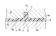
例えば、図8に示すような、突起(例えば、前面カバーを位置決めするためのリブ)2が設けられた樹脂成形品(例えば、エクステンションリフレクター)1を成形する場合、図9に示すように、金型3,4を型締めし、成形面3a,4aによって画成されるキャビティC’を用いて射出成形する。しかし、サイドゲート5aからキャビティC’に射出された溶融樹脂6の一部が、キャビティC’における前記突起2に対応する部分C’1に流入するが、突起対応部C’1が行き止まりのため、これ以上流動できず突起対応部C’1に滞留し、未充填部分7ができる。この未充填部分7には、溶融樹脂6に含まれていた水分や揮発成分がガスとして存在し、溶解樹脂6の射出が進むと未充填部分7が圧縮されて、ガスが成形面3aに沿って金型3,4外に抜け出るが、このガスが抜け出る際の痕跡が、シルバーストリーク(銀条の筋)として樹脂成形品1の意匠面1aに出現し、樹脂成形品1の外観性を低下させる。
そこで、射出成形の際に前記したシルバーストリークが現れないようにする様々な提案がなされている。
たとえば、特許文献1に記載された射出成形方法では、開口部周縁に意匠面よりも厚肉のシールリブを備えたレンズカバー(前面カバーともいう)を射出成形する際に、射出成形開始当初は、サイドバルブゲートからキャビティのシールリブ部分に向けて樹脂を射出し、溶融樹脂が所定位置まで充填された段階で、サイドバルブゲートを閉じて、意匠面バルブゲートからキャビティの意匠面部分に向けて樹脂を射出することで、キャビティ内の途中に溶融樹脂の流れが滞留せず、キャティ内に未充填部分が発生せず、したがって、レンズカバーの意匠面にシルバーストリークが出現しない。
しかし、特許文献1では、成形用の金型にサイドバルブゲートと意匠面バルブゲートの両方を設け、さらには、前記両バルブゲートの開閉を制御する必要があるため、成形装置の構造が複雑となる。
また、成形されたレンズカバーの意匠面には、確かにシルバーストリークが出現しないものの、意匠面バルブゲートの痕跡が新たに残るため、レンズカバーの外観性が改善されるとはいえない。
本発明は、複雑な構造を有する成形装置を用いずに製造された、シルバーストリークが出現しない樹脂成形品を提供することを目的とする。また、本発明は、複雑な構造を有する成形装置を用いずに、シルバーストリークが出現しない樹脂成形品を製造する方法を提供することを目的とする。
本発明の一側面に係る樹脂成形品は、
樹脂成形品本体と、
前記樹脂成形本体と一体的に形成されると共に、前記樹脂成形品本体から突出する突起と、
を備える。
前記樹脂成形品の射出成形では、溶解樹脂は、一対の金型によって画成されたキャビティの前記突起に対応する部分を流動し、
前記突起の背面側には、凹部が形成されており、
前記突起の前面側には、中抜き袋状の膨出部が形成されている。
樹脂成形品本体と、
前記樹脂成形本体と一体的に形成されると共に、前記樹脂成形品本体から突出する突起と、
を備える。
前記樹脂成形品の射出成形では、溶解樹脂は、一対の金型によって画成されたキャビティの前記突起に対応する部分を流動し、
前記突起の背面側には、凹部が形成されており、
前記突起の前面側には、中抜き袋状の膨出部が形成されている。
上記構成によれば、複雑な構造を有する成形装置を用いずに製造された、シルバーストリークが出現しない樹脂成形品を提供することができる。
また、前記樹脂成形品の射出成形では、前記溶解樹脂は、サイドゲートから前記キャビティに射出されてもよい。前記突起は、前記樹脂成形品の意匠面から突出してもよい。
シルバーストリークは、サイドゲートからキャビティの突起に対応する部分(以下、突起対応部という。)を結んだ直線方向に沿って発生するので、シルバーストリークの発生する方向が樹脂成形品の意匠面に向っている場合に問題となる。なお、意匠面とは、自動車用灯具を前方から見た場合に視認できる領域をいい、例えば、バンパー等で隠れて見えない領域を除く。従って、突起が樹脂成形品の意匠面から突出する場合に、本発明は特に有効である。このように、樹脂成形品の意匠面にシルバーストリークが出現しないので、樹脂成形品の外観性を改善できる。
また、前記サイドゲートと前記キャビティの前記突起に対応する部分は、互いに接近するように配置されてもよい。
樹脂成形品の射出成形工程では、サイドゲートからキャビティ内に高圧で溶融樹脂が射出されるため、ゲート近傍では溶融樹脂の移動速度が速い分、キャビティの突起対応部における樹脂の流動も速い。このため、突起対応部の特に樹脂の流れにくい場所に溶融樹脂が滞留し、未充填部分が発生し易い。
従って、サイドゲートと突起対応部が互いに接近するように配置されている場合に、本発明は特に有効である。
従って、サイドゲートと突起対応部が互いに接近するように配置されている場合に、本発明は特に有効である。
具体的には、発明者が考察した結果、突起2が形成された従来の樹脂成形品1(図8)においては、キャビティC’の突起対応部C’1とサイドゲート5aとの間の距離d1が50mm以下となると、突起対応部C’1に樹脂が滞留して、シルバーストリーク(銀条の筋)に繋がる溶融樹脂6の未充填部分7が発生する可能性がある。このため、サイドゲート5aと突起対応部C’1が互いに接近(例えば、距離d1が50mm以下)して配置された金型を用いる場合に、換言すれば、突起2とゲート痕1bとの間の距離が50mm以下となる樹脂成形品1を形成する場合に、本発明は特に有効である。
また、前記膨出部の板厚は、前記膨出部の周辺における前記樹脂成形本体の板厚と略同一であってもよい。
図1及び2に示すように、膨出部の板厚T1が膨出部の周辺における樹脂成形本体の板厚Tと略同一となっているので、図3に示すように、キャビティCの突起対応部C-1は、溶融樹脂の入り口C-1aから出口C-1bまでキャビティCの隙間(間隔)Tと同じ隙間(間隔)T1(=T)で中抜き袋状に延在するので、射出成形の際、突起対応部C-1の入り口C-1aから流入した溶融樹脂は、途中で滞留することなく流動し、出口C-1bからスムーズに流出する。したがって、キャビティCの突起対応部C-1に、シルバーストリーク(銀条の筋)に繋がる溶融樹脂の未充填部分が発生することがさらに抑制される。
本発明の他の側面に係る樹脂成形品は、
樹脂成形品本体と、
前記樹脂成形本体と一体的に形成されると共に、前記樹脂成形品本体から突出する突起と、
を備える。
前記突起の背面側には、凹部が形成され、
前記突起の板厚は、前記突起の周辺における前記樹脂成形本体の部分の板厚と略同一である。
樹脂成形品本体と、
前記樹脂成形本体と一体的に形成されると共に、前記樹脂成形品本体から突出する突起と、
を備える。
前記突起の背面側には、凹部が形成され、
前記突起の板厚は、前記突起の周辺における前記樹脂成形本体の部分の板厚と略同一である。
上記構成によれば、複雑な構造を有する成形装置を用いずに製造された、シルバーストリークが出現しない樹脂成形品を提供することができる。
本発明の一側面に係る前記樹脂成形品を製造する方法は、
凹部を有する上金型と、前記凹部と対向する凸部を有する下金型とを型締めする工程と、
前記上金型と前記下金型との間に形成されたキャビティに溶解樹脂を流し込む工程と、を含む。
前記溶解樹脂は、前記凹部と前記凸部との間に形成された前記キャビティの一部を流動する。
凹部を有する上金型と、前記凹部と対向する凸部を有する下金型とを型締めする工程と、
前記上金型と前記下金型との間に形成されたキャビティに溶解樹脂を流し込む工程と、を含む。
前記溶解樹脂は、前記凹部と前記凸部との間に形成された前記キャビティの一部を流動する。
上記方法によれば、複雑な構造を有する成形装置を用いずに、シルバーストリークが出現しない樹脂成形品を製造する方法を提供することができる。
図面を参照しながら、本発明の実施形態(以下、本実施形態という。)について以下に説明する。
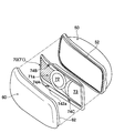
図1~図3は、第1実施形態を示し、図1は第1実施形態に係る樹脂成形品の斜視図である。図2は同樹脂成形品の突起位置における縦断面図である。図3は同樹脂成形品を成形する金型のキャビティの要部断面図である。
図1,2において、自動車用灯具を構成する樹脂成形品10は、平板状に形成された樹脂成形品本体11の意匠面11a側に、他の灯具構成部材との位置決め用または補強用として機能する、樹脂成形品本体11に対し垂直に突出する矩形状の突起12が一体に形成されている。突起12は、図2の(a)および(b)に示すように、その背面側に凹部14が形成されて前面側に膨出する中抜き袋状の膨出部12aで構成されている。そして、突起12を構成する膨出部12aの板厚T1は、樹脂成形品本体11の板厚Tとほぼ同一に形成されている。図1の符号17aは、図3に示すキャビティCによって樹脂成形品10を射出成形する際に付いたゲート痕である。
図3に示す下金型20と上金型30は、樹脂成形品10を射出成形するキャビティCを備えている。下金型20と上金型30を型締めすることで、樹脂成形品10を成形するキャビティCが画成され、ランナ16に導かれた溶融樹脂がサイドゲート17を介してキャビティCに射出される。
即ち、固定側の下金型20に対し、可動側の上金型30が接近離反方向(上下方向)に移動可能に構成され、下金型20と上金型30の対向する分割面には、キャビティCを画成する成形面20a,30aが形成されている。
そして、樹脂成形品10の突起12は、前記したように、中抜き袋状の膨出部12aで構成されているので、下金型20の成形面20aには、突起12の背面側の凹部14に対応する凸部20bが形成され、一方、上金型30の成形面30aには、膨出部12aに対応する凹部30bが形成されている。そして、下金型20と上金型30を型締めすると、下金型20の凸部20bと、上金型30の凹部30bが上下方向に係合し、凸部20bと凹部30b間には、キャビティCの間隔(隙間)Tとほぼ同じ一定の間隔(隙間)T1で凸部20bを包囲するように袋状に延在する、キャビティCの突起12(膨出部12a)に対応する部分である溶融樹脂の流路C-1が構成されている。
そして、サイドゲート17からキャビティCに射出された溶融樹脂は、図3の矢印に示すように、連続する樹脂の流路である突起対応部C-1に流入し滞留することなくスムーズに流動する。詳しくは、キャビティCの突起対応部C-1は、溶融樹脂の入り口C-1aから出口C-1bまでキャビティCの隙間(間隔)Tと同じ隙間(間隔)T1(=T)で中抜き袋状に延在するので、射出成形の際、突起対応部C-1の入り口C-1aから流入した溶融樹脂は、途中で滞留することなく流動し、出口C-1bからスムーズに流出する。そして、キャビティC内全体に樹脂が充填されることで、樹脂成形品10が成形される。
したがって、射出成形の際に、キャビティCの突起対応部C-1に、樹脂成形品10の意匠面11aへのシルバーストリーク(銀条の筋)出現に繋がる溶融樹脂の未充填部分が発生することが極力抑制される。
図4~7は、樹脂成形品をエクステンションリフレクターに適用した例を示す。
自動車用ヘッドランプは、図4に示すように、灯室を形成する、前面側が開口する容器状のランプボディ50内に、所定の配光を形成する2つの光源ユニット(図示せず)が左右に隣接して配置されるとともに、ランプボディ50の前面開口部には、前面カバー60が組み付けられ、前面カバー60の内側には、灯室内全体を一体的に見せる、例えば黒色のエクステンションリフレクター70が組み付けられている。
エクステンションリフレクター70は、前面カバー60に倣って湾曲する形状のエクステンションリフレクター本体71で構成され、光源ユニットの発光を妨げないための開口部72,73が形成されるとともに、光源ユニットを除く灯室内部を隠すべくランプボディ50の前面開口部に沿って三次元方向に延在する複雑な形状に形成されており、軽量にして成形時の流動性に優れたPBT系材料によって構成されている。
そして、前面カバー60およびエクステンションリフレクター70をランプボディ50に組み付けるには、前面カバー60にエクステンションリフレクター70を締結ねじ80(図5参照)によって予め固定一体化しておき、前面カバー60の周縁部に形成されているシール脚62を、ランプボディ50の前面開口部の周縁部に形成されているシール溝52に組み付けることで、例えば、シール脚62とシール溝52間の凹凸ランス係合部(図示せず)が係合し、ランプボディ50と前面カバー60が抜け止め固定される。符号54は、シール材である。
また、前面カバー60の背面の所定の3箇所にボス64が突出形成され、一方、エクステンションリフレクター70(エクステンションリフレクター本体71)の前面側の前記ボス64に対応する所定位置には、前面カバー60とエクステンションリフレクター70をねじ固定する際に、前面カバー60側のボス64がそれぞれ当接できる位置決用の突起74(74A,74B,74C)、締結ねじ80および挿通用の円孔75が設けられている(図4,5参照)。本例では、位置決用の突起74および円孔75は、図4に示すように、エクステンションリフレクター70の下側縁の開口部72,73の近傍および上側縁の開口部72の左側に設けられている。
位置決用の突起74は、図6の(a)および(b)に示すように、その背面側に凹部76が形成されて前面側に膨出する中抜き袋状の膨出部74aで構成されている。エクステンションリフレクター本体71は全体がほぼ一定の厚さtに形成されるとともに、膨出部74aを構成する板厚t1も、エクステンションリフレクター本体71における突起74(膨出部74a)周辺領域の板厚tとほぼ同じ厚さ(t1=t)となっている。後で詳しく説明するが、エクステンションリフレクター70を射出成形する際に、エクステンションリフレクター70を成形するキャビティC1の突起74に対応する部分C1-1を溶融樹脂がスムーズに流動して、位置決用突起対応部C1-1に溶融樹脂が滞留しない構造となっている。
また、図5に示すように、透明な前面カバー60の前面側周縁部の全周には、黒色の表面樹脂層61が形成されており、エクステンションリフレクター70とのねじ固定部を含む、エクステンションリフレクター70の周縁領域全体を隠すことで、ヘッドランプの前方からの外観性(非視認性)が向上している。
このため、エクステンションリフレクター70は、透明な前面カバー60を通じてその中央部付近が見えるものの、その周縁部は、前面カバー60の黒色表面樹脂層61によって隠れて見えない。即ち、前面カバー60を通じて見える、図5の符号71aで示す範囲がエクステンションリフレクター70の意匠面となる。
次に、図7を参照することで、エクステンションリフレクター70を射出成形する際に、溶解樹脂が射出されるキャビティC1について以下に説明する。
固定側の下金型120の成形面120aと、下金型120に対し接近離反方向に移動可能な可動側の上金型130の成形面130aによって、エクステンションリフレクター70を成形するためのキャビティC1が画成されている。
また、金型120,130の分割面の所定位置には、樹脂通路であるランナ140に連通し、キャビティC1に樹脂を射出するサイドゲート142が設けられている。サイドゲート142は、下金型120と上金型130により形成されるキャビティC1内に射出された溶融樹脂が効率よく短時間でキャビティC1内全体に充填されるように、キャビティC1の容積がゲートを挟んで左右方向にほぼ等しくなる所定位置に設けられている。詳しくは、エクステンションリフレクター70には、図4に示すように、2つの開口部72,73が左右方向右寄りに設けられているので、成形されたエクステンションリフレクター70の左右方向中央部よりも幾分左寄りに残るゲート痕142a(図4,5参照)に対応する、キャビティC1の所定位置にサイドゲート142(図7参照)が設けられている。
さらに詳しくは、溶融樹脂が射出されるサイドゲート142とキャビティCの突起74Aに対応する突起対応部C1-1との間の距離dが50mm以下となるように、サイドゲート142は突起対応部C-1に近接配置されている。エクステンションリフレクター70の意匠面71a(図4の斜線で示す領域)は、サイドゲート142とキャビティC1の突起対応部C1-1を結ぶ直線上、換言すれば、成形品であるエクステンションリフレクター70のゲート痕142aと突起74Aを結ぶ直線上に位置することになる。
このため、エクステンションリフレクター70を射出成形する際に、キャビティC1の突起対応部C1-1に、溶融樹脂の未充填部分が発生した場合には、エクステンションリフレクター70の意匠面71aにシルバーストリーク(銀条の筋)が出現する可能性がある。
本実施例では、突起74Aが、その背面側に凹部76が形成されて前面側に膨出する中抜き袋状の膨出部74aで構成されているので、キャビティC1の突起対応部C1-1は、一定の隙間(t1)を保持して中抜き袋状に延在して、連続する樹脂の流路であるキャビティC1の一部を構成している。
このため、サイドゲート142からキャビティC1に射出された溶融樹脂(PBT系材料)は、図7の矢印に示すように、連続する樹脂の流路である突起対応部C1-1に流入し滞留することなくスムーズに流動して、キャビティC1内全体に溶融樹脂が充填される。したがって、射出成形の際に、シルバーストリーク出現の原因となる、キャビティC1の突起対応部C1-1に溶融樹脂の未充填部分が発生することはない。よって、キャビティC1によって成形されたエクステンションリフレクター70の意匠面71aには、シルバーストリークが出現せず(又は、シルバーストリークの出現が極力抑制され)、外観性に優れたエクステンションリフレクター70を成形できる。
本実施例では、エクステンションリフレクター70に設けられた3個の位置決め用突起74(74A,74B,74C)のすべてが、その背面側に凹部76が形成されて前面側に膨出する中抜き袋状の膨出部74aで構成されているが、そもそもキャビティC1の突起74B,74Cに対応する部分は、いずれもサイドゲート142から50mm以上離れた位置にある、さらに、ゲート痕142aと突起74B,74Cを結ぶ直線上にエクステンションリフレクター70の意匠面71aは位置されない。
このため、エクステンションリフレクタ―70の射出成形の際、キャビティC1の突起74B,74Cにそれぞれ対応する部分に溶融樹脂の滞留が仮に発生したとしても、エクステンションリフレクター70の意匠面71aにシルバーストリークが出現することはない(又は、シルバーストリークの出現が極力抑制される)。
したがって、位置決め用突起74B,74Cは、突起74Aのように、その背面側に凹部76が形成されて前面側に膨出する中抜き袋状に構成する必要はなく、所定の厚みをもつ従来公知の中実板状に構成してもよい。
また、本実施例では、前面カバー60を固定する際に用いる位置決用の突起74A,74B,74Cが設けられたエクステンションリフレクター70について説明しているが、補強用のリブが設けられたエクステンションリフレクターや、位置決め用の突起や補強用のリブが設けられたランプボディ(灯具ボディ)に本発明を適用してもよい。
以上、本発明の実施形態について説明をしたが、本発明の技術的範囲が本実施形態の説明によって限定的に解釈されるべきではないのは言うまでもない。本実施形態は単なる一例であって、特許請求の範囲に記載された発明の範囲内において、様々な実施形態の変更が可能であることが当業者によって理解されるところである。本発明の技術的範囲は特許請求の範囲に記載された発明の範囲及びその均等の範囲に基づいて定められるべきである。
本出願は、2015年6月23日に出願された日本国特許出願(特願2015-125349号)に開示された内容を適宜援用する。
Claims (6)
- 樹脂成形品本体と、
前記樹脂成形本体と一体的に形成されると共に、前記樹脂成形品本体から突出する突起と、
を備えた樹脂成形品であって、
前記樹脂成形品の射出成形では、溶解樹脂は、一対の金型によって画成されたキャビティの前記突起に対応する部分を流動し、
前記突起の背面側には、凹部が形成されており、
前記突起の前面側には、中抜き袋状の膨出部が形成されている、樹脂成形品。 - 前記樹脂成形品の射出成形では、前記溶解樹脂は、サイドゲートから前記キャビティに射出され、
前記突起は、前記樹脂成形品の意匠面から突出する、請求項1に記載の樹脂成形品。 - 前記サイドゲートと前記キャビティの前記突起に対応する部分は、互いに接近するように配置されている、請求項2に記載の樹脂成形品。
- 前記膨出部の板厚は、前記膨出部の周辺における前記樹脂成形本体の板厚と略同一である、請求項1から3のうち何れか一項に記載の樹脂成形品。
- 樹脂成形品本体と、
前記樹脂成形本体と一体的に形成されると共に、前記樹脂成形品本体から突出する突起と、
を備え、
前記突起の背面側には、凹部が形成され、
前記突起の板厚は、前記突起の周辺における前記樹脂成形本体の部分の板厚と略同一である、樹脂成形品。 - 凹部を有する上金型と、前記凹部と対向する凸部を有する下金型とを型締めする工程と、
前記上金型と前記下金型との間に形成されたキャビティに溶解樹脂を流し込む工程と、を含み、
前記溶解樹脂は、前記凹部と前記凸部との間に形成された前記キャビティの一部を流動する、請求項5に記載の樹脂成形品を製造する方法。
Priority Applications (2)
| Application Number | Priority Date | Filing Date | Title |
|---|---|---|---|
| US15/738,937 US11203137B2 (en) | 2015-06-23 | 2016-06-02 | Resin molded product and method for producing resin molded product |
| CN201680036779.XA CN107735239A (zh) | 2015-06-23 | 2016-06-02 | 树脂成型品及制造树脂成型品的方法 |
Applications Claiming Priority (2)
| Application Number | Priority Date | Filing Date | Title |
|---|---|---|---|
| JP2015125349A JP6666082B2 (ja) | 2015-06-23 | 2015-06-23 | 樹脂成形品 |
| JP2015-125349 | 2015-06-23 |
Publications (1)
| Publication Number | Publication Date |
|---|---|
| WO2016208355A1 true WO2016208355A1 (ja) | 2016-12-29 |
Family
ID=57585412
Family Applications (1)
| Application Number | Title | Priority Date | Filing Date |
|---|---|---|---|
| PCT/JP2016/066493 Ceased WO2016208355A1 (ja) | 2015-06-23 | 2016-06-02 | 樹脂成形品及び樹脂成形品を製造する方法 |
Country Status (4)
| Country | Link |
|---|---|
| US (1) | US11203137B2 (ja) |
| JP (1) | JP6666082B2 (ja) |
| CN (1) | CN107735239A (ja) |
| WO (1) | WO2016208355A1 (ja) |
Families Citing this family (5)
| Publication number | Priority date | Publication date | Assignee | Title |
|---|---|---|---|---|
| JP7036612B2 (ja) * | 2018-02-13 | 2022-03-15 | 株式会社小糸製作所 | 樹脂成形品 |
| CN110341113A (zh) * | 2019-08-09 | 2019-10-18 | 华域视觉科技(上海)有限公司 | 一种车灯配光镜视认角花纹结构及车灯 |
| JP7368219B2 (ja) * | 2019-12-17 | 2023-10-24 | 日本プラスト株式会社 | 樹脂成形品 |
| EP4644767A1 (en) | 2022-12-28 | 2025-11-05 | Koito Manufacturing Co., Ltd. | Vehicular lamp |
| JP7789131B1 (ja) | 2024-06-24 | 2025-12-19 | 森六株式会社 | 樹脂成形品 |
Citations (6)
| Publication number | Priority date | Publication date | Assignee | Title |
|---|---|---|---|---|
| JP2001132566A (ja) * | 1999-11-05 | 2001-05-15 | Honda Motor Co Ltd | エンジンの吸気系部品およびその製造方法 |
| JP2004237586A (ja) * | 2003-02-06 | 2004-08-26 | Koito Mfg Co Ltd | 車両灯具用樹脂部品の親子取り成形方法および成形装置 |
| JP2009096105A (ja) * | 2007-10-18 | 2009-05-07 | Koito Mfg Co Ltd | 車両用灯具の前面カバー |
| JP2010214749A (ja) * | 2009-03-17 | 2010-09-30 | Stanley Electric Co Ltd | 車両用灯具のレンズカバー製造方法 |
| JP2011194624A (ja) * | 2010-03-18 | 2011-10-06 | Stanley Electric Co Ltd | レンズカバー成形用金型およびレンズカバーの製造方法 |
| JP2013199012A (ja) * | 2012-03-23 | 2013-10-03 | Stanley Electric Co Ltd | 車両用灯具のレンズカバー製造方法 |
Family Cites Families (7)
| Publication number | Priority date | Publication date | Assignee | Title |
|---|---|---|---|---|
| JP2738059B2 (ja) * | 1989-09-29 | 1998-04-08 | 橋本フォーミング工業株式会社 | 射出成形型 |
| WO2002032643A1 (en) * | 2000-10-19 | 2002-04-25 | Infiltrator Systems, Inc. | Gate flow diverter, mold for use therewith; and method for use thereof |
| JP5005422B2 (ja) * | 2007-05-09 | 2012-08-22 | 株式会社エンプラス | 射出成形ギヤ |
| JP4553932B2 (ja) * | 2007-11-27 | 2010-09-29 | スタンレー電気株式会社 | レンズカバー製造方法 |
| JP5451410B2 (ja) * | 2010-01-14 | 2014-03-26 | スタンレー電気株式会社 | プロジェクタ型前照灯及びその樹脂製投影レンズの配置構造 |
| EP2656997B1 (en) * | 2012-04-23 | 2020-08-12 | ABB Schweiz AG | Method for injection moulding of thermoplastic pole parts, and mould for proceeding the same |
| JP6037502B2 (ja) * | 2012-09-27 | 2016-12-07 | 日本プラスト株式会社 | 樹脂成形品 |
-
2015
- 2015-06-23 JP JP2015125349A patent/JP6666082B2/ja active Active
-
2016
- 2016-06-02 WO PCT/JP2016/066493 patent/WO2016208355A1/ja not_active Ceased
- 2016-06-02 CN CN201680036779.XA patent/CN107735239A/zh active Pending
- 2016-06-02 US US15/738,937 patent/US11203137B2/en active Active
Patent Citations (6)
| Publication number | Priority date | Publication date | Assignee | Title |
|---|---|---|---|---|
| JP2001132566A (ja) * | 1999-11-05 | 2001-05-15 | Honda Motor Co Ltd | エンジンの吸気系部品およびその製造方法 |
| JP2004237586A (ja) * | 2003-02-06 | 2004-08-26 | Koito Mfg Co Ltd | 車両灯具用樹脂部品の親子取り成形方法および成形装置 |
| JP2009096105A (ja) * | 2007-10-18 | 2009-05-07 | Koito Mfg Co Ltd | 車両用灯具の前面カバー |
| JP2010214749A (ja) * | 2009-03-17 | 2010-09-30 | Stanley Electric Co Ltd | 車両用灯具のレンズカバー製造方法 |
| JP2011194624A (ja) * | 2010-03-18 | 2011-10-06 | Stanley Electric Co Ltd | レンズカバー成形用金型およびレンズカバーの製造方法 |
| JP2013199012A (ja) * | 2012-03-23 | 2013-10-03 | Stanley Electric Co Ltd | 車両用灯具のレンズカバー製造方法 |
Also Published As
| Publication number | Publication date |
|---|---|
| JP2017007214A (ja) | 2017-01-12 |
| US20180194046A1 (en) | 2018-07-12 |
| US11203137B2 (en) | 2021-12-21 |
| CN107735239A (zh) | 2018-02-23 |
| JP6666082B2 (ja) | 2020-03-13 |
Similar Documents
| Publication | Publication Date | Title |
|---|---|---|
| US8393772B2 (en) | Vehicle lamp | |
| JP6666082B2 (ja) | 樹脂成形品 | |
| KR100211202B1 (ko) | 차량램프와 그 제조장치 및 제조방법 | |
| CN106881807B (zh) | 树脂成型品 | |
| CN107921684B (zh) | 树脂成型品和成型装置 | |
| JP2013199012A (ja) | 車両用灯具のレンズカバー製造方法 | |
| KR20190098055A (ko) | 수지 성형품 | |
| JP6598601B2 (ja) | 自動車用灯具用前面カバーおよび金型装置 | |
| JP6768396B2 (ja) | 射出成形品 | |
| JP6181483B2 (ja) | 射出成形品および射出成形装置 | |
| JP4679203B2 (ja) | 樹脂製リング形状品の射出成形型 | |
| JP6487334B2 (ja) | 投影レンズ及びそれを備えた車両用灯具 | |
| US8470233B2 (en) | Metal mold for use in molding lens cover and method for producing lens cover | |
| JP2017205978A (ja) | 二色成形品および二色成形品の製造方法 | |
| JP7036720B2 (ja) | 金型および二色成形品の製造方法 | |
| KR100912855B1 (ko) | 발포금형 | |
| JP6602296B2 (ja) | 金型 | |
| CN101769494B (zh) | 车灯 | |
| JP6382591B2 (ja) | 樹脂成形品の製造方法 | |
| JP2015153629A (ja) | 投影レンズ及びそれを備えた車両用灯具 | |
| JPH07124985A (ja) | 射出中空成形方法 | |
| JP5000208B2 (ja) | 樹脂成形品 | |
| JP7175749B2 (ja) | 射出成形方法 | |
| JP5186321B2 (ja) | パッド付きインストルメントパネル及びその製造方法 | |
| JP4551789B2 (ja) | 樹脂製リング形状品及びその射出成形方法 |
Legal Events
| Date | Code | Title | Description |
|---|---|---|---|
| 121 | Ep: the epo has been informed by wipo that ep was designated in this application |
Ref document number: 16814126 Country of ref document: EP Kind code of ref document: A1 |
|
| NENP | Non-entry into the national phase |
Ref country code: DE |
|
| 122 | Ep: pct application non-entry in european phase |
Ref document number: 16814126 Country of ref document: EP Kind code of ref document: A1 |