WO2016199922A1 - 合金化溶融亜鉛めっき鋼板およびその製造方法 - Google Patents
合金化溶融亜鉛めっき鋼板およびその製造方法 Download PDFInfo
- Publication number
- WO2016199922A1 WO2016199922A1 PCT/JP2016/067448 JP2016067448W WO2016199922A1 WO 2016199922 A1 WO2016199922 A1 WO 2016199922A1 JP 2016067448 W JP2016067448 W JP 2016067448W WO 2016199922 A1 WO2016199922 A1 WO 2016199922A1
- Authority
- WO
- WIPO (PCT)
- Prior art keywords
- steel sheet
- hot
- dip galvanized
- cooling
- cold
- Prior art date
- Legal status (The legal status is an assumption and is not a legal conclusion. Google has not performed a legal analysis and makes no representation as to the accuracy of the status listed.)
- Ceased
Links
Classifications
-
- C—CHEMISTRY; METALLURGY
- C21—METALLURGY OF IRON
- C21D—MODIFYING THE PHYSICAL STRUCTURE OF FERROUS METALS; GENERAL DEVICES FOR HEAT TREATMENT OF FERROUS OR NON-FERROUS METALS OR ALLOYS; MAKING METAL MALLEABLE, e.g. BY DECARBURISATION OR TEMPERING
- C21D9/00—Heat treatment, e.g. annealing, hardening, quenching or tempering, adapted for particular articles; Furnaces therefor
- C21D9/46—Heat treatment, e.g. annealing, hardening, quenching or tempering, adapted for particular articles; Furnaces therefor for sheet metals
-
- B—PERFORMING OPERATIONS; TRANSPORTING
- B32—LAYERED PRODUCTS
- B32B—LAYERED PRODUCTS, i.e. PRODUCTS BUILT-UP OF STRATA OF FLAT OR NON-FLAT, e.g. CELLULAR OR HONEYCOMB, FORM
- B32B15/00—Layered products comprising a layer of metal
-
- B—PERFORMING OPERATIONS; TRANSPORTING
- B32—LAYERED PRODUCTS
- B32B—LAYERED PRODUCTS, i.e. PRODUCTS BUILT-UP OF STRATA OF FLAT OR NON-FLAT, e.g. CELLULAR OR HONEYCOMB, FORM
- B32B15/00—Layered products comprising a layer of metal
- B32B15/01—Layered products comprising a layer of metal all layers being exclusively metallic
- B32B15/013—Layered products comprising a layer of metal all layers being exclusively metallic one layer being formed of an iron alloy or steel, another layer being formed of a metal other than iron or aluminium
-
- B—PERFORMING OPERATIONS; TRANSPORTING
- B32—LAYERED PRODUCTS
- B32B—LAYERED PRODUCTS, i.e. PRODUCTS BUILT-UP OF STRATA OF FLAT OR NON-FLAT, e.g. CELLULAR OR HONEYCOMB, FORM
- B32B15/00—Layered products comprising a layer of metal
- B32B15/04—Layered products comprising a layer of metal comprising metal as the main or only constituent of a layer, which is next to another layer of the same or of a different material
- B32B15/043—Layered products comprising a layer of metal comprising metal as the main or only constituent of a layer, which is next to another layer of the same or of a different material of metal
-
- B—PERFORMING OPERATIONS; TRANSPORTING
- B32—LAYERED PRODUCTS
- B32B—LAYERED PRODUCTS, i.e. PRODUCTS BUILT-UP OF STRATA OF FLAT OR NON-FLAT, e.g. CELLULAR OR HONEYCOMB, FORM
- B32B15/00—Layered products comprising a layer of metal
- B32B15/18—Layered products comprising a layer of metal comprising iron or steel
-
- C—CHEMISTRY; METALLURGY
- C21—METALLURGY OF IRON
- C21D—MODIFYING THE PHYSICAL STRUCTURE OF FERROUS METALS; GENERAL DEVICES FOR HEAT TREATMENT OF FERROUS OR NON-FERROUS METALS OR ALLOYS; MAKING METAL MALLEABLE, e.g. BY DECARBURISATION OR TEMPERING
- C21D1/00—General methods or devices for heat treatment, e.g. annealing, hardening, quenching or tempering
- C21D1/26—Methods of annealing
-
- C—CHEMISTRY; METALLURGY
- C21—METALLURGY OF IRON
- C21D—MODIFYING THE PHYSICAL STRUCTURE OF FERROUS METALS; GENERAL DEVICES FOR HEAT TREATMENT OF FERROUS OR NON-FERROUS METALS OR ALLOYS; MAKING METAL MALLEABLE, e.g. BY DECARBURISATION OR TEMPERING
- C21D6/00—Heat treatment of ferrous alloys
- C21D6/004—Heat treatment of ferrous alloys containing Cr and Ni
-
- C—CHEMISTRY; METALLURGY
- C21—METALLURGY OF IRON
- C21D—MODIFYING THE PHYSICAL STRUCTURE OF FERROUS METALS; GENERAL DEVICES FOR HEAT TREATMENT OF FERROUS OR NON-FERROUS METALS OR ALLOYS; MAKING METAL MALLEABLE, e.g. BY DECARBURISATION OR TEMPERING
- C21D6/00—Heat treatment of ferrous alloys
- C21D6/005—Heat treatment of ferrous alloys containing Mn
-
- C—CHEMISTRY; METALLURGY
- C21—METALLURGY OF IRON
- C21D—MODIFYING THE PHYSICAL STRUCTURE OF FERROUS METALS; GENERAL DEVICES FOR HEAT TREATMENT OF FERROUS OR NON-FERROUS METALS OR ALLOYS; MAKING METAL MALLEABLE, e.g. BY DECARBURISATION OR TEMPERING
- C21D6/00—Heat treatment of ferrous alloys
- C21D6/008—Heat treatment of ferrous alloys containing Si
-
- C—CHEMISTRY; METALLURGY
- C21—METALLURGY OF IRON
- C21D—MODIFYING THE PHYSICAL STRUCTURE OF FERROUS METALS; GENERAL DEVICES FOR HEAT TREATMENT OF FERROUS OR NON-FERROUS METALS OR ALLOYS; MAKING METAL MALLEABLE, e.g. BY DECARBURISATION OR TEMPERING
- C21D8/00—Modifying the physical properties of ferrous metals or ferrous alloys by deformation combined with, or followed by, heat treatment
- C21D8/02—Modifying the physical properties of ferrous metals or ferrous alloys by deformation combined with, or followed by, heat treatment during manufacturing of plates or strips
- C21D8/0221—Modifying the physical properties of ferrous metals or ferrous alloys by deformation combined with, or followed by, heat treatment during manufacturing of plates or strips characterised by the working steps
- C21D8/0226—Hot rolling
-
- C—CHEMISTRY; METALLURGY
- C21—METALLURGY OF IRON
- C21D—MODIFYING THE PHYSICAL STRUCTURE OF FERROUS METALS; GENERAL DEVICES FOR HEAT TREATMENT OF FERROUS OR NON-FERROUS METALS OR ALLOYS; MAKING METAL MALLEABLE, e.g. BY DECARBURISATION OR TEMPERING
- C21D8/00—Modifying the physical properties of ferrous metals or ferrous alloys by deformation combined with, or followed by, heat treatment
- C21D8/02—Modifying the physical properties of ferrous metals or ferrous alloys by deformation combined with, or followed by, heat treatment during manufacturing of plates or strips
- C21D8/0221—Modifying the physical properties of ferrous metals or ferrous alloys by deformation combined with, or followed by, heat treatment during manufacturing of plates or strips characterised by the working steps
- C21D8/0236—Cold rolling
-
- C—CHEMISTRY; METALLURGY
- C21—METALLURGY OF IRON
- C21D—MODIFYING THE PHYSICAL STRUCTURE OF FERROUS METALS; GENERAL DEVICES FOR HEAT TREATMENT OF FERROUS OR NON-FERROUS METALS OR ALLOYS; MAKING METAL MALLEABLE, e.g. BY DECARBURISATION OR TEMPERING
- C21D8/00—Modifying the physical properties of ferrous metals or ferrous alloys by deformation combined with, or followed by, heat treatment
- C21D8/02—Modifying the physical properties of ferrous metals or ferrous alloys by deformation combined with, or followed by, heat treatment during manufacturing of plates or strips
- C21D8/0247—Modifying the physical properties of ferrous metals or ferrous alloys by deformation combined with, or followed by, heat treatment during manufacturing of plates or strips characterised by the heat treatment
- C21D8/0263—Modifying the physical properties of ferrous metals or ferrous alloys by deformation combined with, or followed by, heat treatment during manufacturing of plates or strips characterised by the heat treatment following hot rolling
-
- C—CHEMISTRY; METALLURGY
- C21—METALLURGY OF IRON
- C21D—MODIFYING THE PHYSICAL STRUCTURE OF FERROUS METALS; GENERAL DEVICES FOR HEAT TREATMENT OF FERROUS OR NON-FERROUS METALS OR ALLOYS; MAKING METAL MALLEABLE, e.g. BY DECARBURISATION OR TEMPERING
- C21D8/00—Modifying the physical properties of ferrous metals or ferrous alloys by deformation combined with, or followed by, heat treatment
- C21D8/02—Modifying the physical properties of ferrous metals or ferrous alloys by deformation combined with, or followed by, heat treatment during manufacturing of plates or strips
- C21D8/0278—Modifying the physical properties of ferrous metals or ferrous alloys by deformation combined with, or followed by, heat treatment during manufacturing of plates or strips involving a particular surface treatment
-
- C—CHEMISTRY; METALLURGY
- C22—METALLURGY; FERROUS OR NON-FERROUS ALLOYS; TREATMENT OF ALLOYS OR NON-FERROUS METALS
- C22C—ALLOYS
- C22C18/00—Alloys based on zinc
-
- C—CHEMISTRY; METALLURGY
- C22—METALLURGY; FERROUS OR NON-FERROUS ALLOYS; TREATMENT OF ALLOYS OR NON-FERROUS METALS
- C22C—ALLOYS
- C22C38/00—Ferrous alloys, e.g. steel alloys
-
- C—CHEMISTRY; METALLURGY
- C22—METALLURGY; FERROUS OR NON-FERROUS ALLOYS; TREATMENT OF ALLOYS OR NON-FERROUS METALS
- C22C—ALLOYS
- C22C38/00—Ferrous alloys, e.g. steel alloys
- C22C38/001—Ferrous alloys, e.g. steel alloys containing N
-
- C—CHEMISTRY; METALLURGY
- C22—METALLURGY; FERROUS OR NON-FERROUS ALLOYS; TREATMENT OF ALLOYS OR NON-FERROUS METALS
- C22C—ALLOYS
- C22C38/00—Ferrous alloys, e.g. steel alloys
- C22C38/002—Ferrous alloys, e.g. steel alloys containing In, Mg, or other elements not provided for in one single group C22C38/001 - C22C38/60
-
- C—CHEMISTRY; METALLURGY
- C22—METALLURGY; FERROUS OR NON-FERROUS ALLOYS; TREATMENT OF ALLOYS OR NON-FERROUS METALS
- C22C—ALLOYS
- C22C38/00—Ferrous alloys, e.g. steel alloys
- C22C38/005—Ferrous alloys, e.g. steel alloys containing rare earths, i.e. Sc, Y, Lanthanides
-
- C—CHEMISTRY; METALLURGY
- C22—METALLURGY; FERROUS OR NON-FERROUS ALLOYS; TREATMENT OF ALLOYS OR NON-FERROUS METALS
- C22C—ALLOYS
- C22C38/00—Ferrous alloys, e.g. steel alloys
- C22C38/008—Ferrous alloys, e.g. steel alloys containing tin
-
- C—CHEMISTRY; METALLURGY
- C22—METALLURGY; FERROUS OR NON-FERROUS ALLOYS; TREATMENT OF ALLOYS OR NON-FERROUS METALS
- C22C—ALLOYS
- C22C38/00—Ferrous alloys, e.g. steel alloys
- C22C38/02—Ferrous alloys, e.g. steel alloys containing silicon
-
- C—CHEMISTRY; METALLURGY
- C22—METALLURGY; FERROUS OR NON-FERROUS ALLOYS; TREATMENT OF ALLOYS OR NON-FERROUS METALS
- C22C—ALLOYS
- C22C38/00—Ferrous alloys, e.g. steel alloys
- C22C38/04—Ferrous alloys, e.g. steel alloys containing manganese
-
- C—CHEMISTRY; METALLURGY
- C22—METALLURGY; FERROUS OR NON-FERROUS ALLOYS; TREATMENT OF ALLOYS OR NON-FERROUS METALS
- C22C—ALLOYS
- C22C38/00—Ferrous alloys, e.g. steel alloys
- C22C38/06—Ferrous alloys, e.g. steel alloys containing aluminium
-
- C—CHEMISTRY; METALLURGY
- C22—METALLURGY; FERROUS OR NON-FERROUS ALLOYS; TREATMENT OF ALLOYS OR NON-FERROUS METALS
- C22C—ALLOYS
- C22C38/00—Ferrous alloys, e.g. steel alloys
- C22C38/08—Ferrous alloys, e.g. steel alloys containing nickel
-
- C—CHEMISTRY; METALLURGY
- C22—METALLURGY; FERROUS OR NON-FERROUS ALLOYS; TREATMENT OF ALLOYS OR NON-FERROUS METALS
- C22C—ALLOYS
- C22C38/00—Ferrous alloys, e.g. steel alloys
- C22C38/10—Ferrous alloys, e.g. steel alloys containing cobalt
-
- C—CHEMISTRY; METALLURGY
- C22—METALLURGY; FERROUS OR NON-FERROUS ALLOYS; TREATMENT OF ALLOYS OR NON-FERROUS METALS
- C22C—ALLOYS
- C22C38/00—Ferrous alloys, e.g. steel alloys
- C22C38/10—Ferrous alloys, e.g. steel alloys containing cobalt
- C22C38/105—Ferrous alloys, e.g. steel alloys containing cobalt containing Co and Ni
-
- C—CHEMISTRY; METALLURGY
- C22—METALLURGY; FERROUS OR NON-FERROUS ALLOYS; TREATMENT OF ALLOYS OR NON-FERROUS METALS
- C22C—ALLOYS
- C22C38/00—Ferrous alloys, e.g. steel alloys
- C22C38/12—Ferrous alloys, e.g. steel alloys containing tungsten, tantalum, molybdenum, vanadium, or niobium
-
- C—CHEMISTRY; METALLURGY
- C22—METALLURGY; FERROUS OR NON-FERROUS ALLOYS; TREATMENT OF ALLOYS OR NON-FERROUS METALS
- C22C—ALLOYS
- C22C38/00—Ferrous alloys, e.g. steel alloys
- C22C38/14—Ferrous alloys, e.g. steel alloys containing titanium or zirconium
-
- C—CHEMISTRY; METALLURGY
- C22—METALLURGY; FERROUS OR NON-FERROUS ALLOYS; TREATMENT OF ALLOYS OR NON-FERROUS METALS
- C22C—ALLOYS
- C22C38/00—Ferrous alloys, e.g. steel alloys
- C22C38/16—Ferrous alloys, e.g. steel alloys containing copper
-
- C—CHEMISTRY; METALLURGY
- C22—METALLURGY; FERROUS OR NON-FERROUS ALLOYS; TREATMENT OF ALLOYS OR NON-FERROUS METALS
- C22C—ALLOYS
- C22C38/00—Ferrous alloys, e.g. steel alloys
- C22C38/18—Ferrous alloys, e.g. steel alloys containing chromium
-
- C—CHEMISTRY; METALLURGY
- C22—METALLURGY; FERROUS OR NON-FERROUS ALLOYS; TREATMENT OF ALLOYS OR NON-FERROUS METALS
- C22C—ALLOYS
- C22C38/00—Ferrous alloys, e.g. steel alloys
- C22C38/18—Ferrous alloys, e.g. steel alloys containing chromium
- C22C38/20—Ferrous alloys, e.g. steel alloys containing chromium with copper
-
- C—CHEMISTRY; METALLURGY
- C22—METALLURGY; FERROUS OR NON-FERROUS ALLOYS; TREATMENT OF ALLOYS OR NON-FERROUS METALS
- C22C—ALLOYS
- C22C38/00—Ferrous alloys, e.g. steel alloys
- C22C38/18—Ferrous alloys, e.g. steel alloys containing chromium
- C22C38/22—Ferrous alloys, e.g. steel alloys containing chromium with molybdenum or tungsten
-
- C—CHEMISTRY; METALLURGY
- C22—METALLURGY; FERROUS OR NON-FERROUS ALLOYS; TREATMENT OF ALLOYS OR NON-FERROUS METALS
- C22C—ALLOYS
- C22C38/00—Ferrous alloys, e.g. steel alloys
- C22C38/18—Ferrous alloys, e.g. steel alloys containing chromium
- C22C38/24—Ferrous alloys, e.g. steel alloys containing chromium with vanadium
-
- C—CHEMISTRY; METALLURGY
- C22—METALLURGY; FERROUS OR NON-FERROUS ALLOYS; TREATMENT OF ALLOYS OR NON-FERROUS METALS
- C22C—ALLOYS
- C22C38/00—Ferrous alloys, e.g. steel alloys
- C22C38/18—Ferrous alloys, e.g. steel alloys containing chromium
- C22C38/26—Ferrous alloys, e.g. steel alloys containing chromium with niobium or tantalum
-
- C—CHEMISTRY; METALLURGY
- C22—METALLURGY; FERROUS OR NON-FERROUS ALLOYS; TREATMENT OF ALLOYS OR NON-FERROUS METALS
- C22C—ALLOYS
- C22C38/00—Ferrous alloys, e.g. steel alloys
- C22C38/18—Ferrous alloys, e.g. steel alloys containing chromium
- C22C38/28—Ferrous alloys, e.g. steel alloys containing chromium with titanium or zirconium
-
- C—CHEMISTRY; METALLURGY
- C22—METALLURGY; FERROUS OR NON-FERROUS ALLOYS; TREATMENT OF ALLOYS OR NON-FERROUS METALS
- C22C—ALLOYS
- C22C38/00—Ferrous alloys, e.g. steel alloys
- C22C38/18—Ferrous alloys, e.g. steel alloys containing chromium
- C22C38/30—Ferrous alloys, e.g. steel alloys containing chromium with cobalt
-
- C—CHEMISTRY; METALLURGY
- C22—METALLURGY; FERROUS OR NON-FERROUS ALLOYS; TREATMENT OF ALLOYS OR NON-FERROUS METALS
- C22C—ALLOYS
- C22C38/00—Ferrous alloys, e.g. steel alloys
- C22C38/18—Ferrous alloys, e.g. steel alloys containing chromium
- C22C38/32—Ferrous alloys, e.g. steel alloys containing chromium with boron
-
- C—CHEMISTRY; METALLURGY
- C22—METALLURGY; FERROUS OR NON-FERROUS ALLOYS; TREATMENT OF ALLOYS OR NON-FERROUS METALS
- C22C—ALLOYS
- C22C38/00—Ferrous alloys, e.g. steel alloys
- C22C38/18—Ferrous alloys, e.g. steel alloys containing chromium
- C22C38/34—Ferrous alloys, e.g. steel alloys containing chromium with more than 1.5% by weight of silicon
-
- C—CHEMISTRY; METALLURGY
- C22—METALLURGY; FERROUS OR NON-FERROUS ALLOYS; TREATMENT OF ALLOYS OR NON-FERROUS METALS
- C22C—ALLOYS
- C22C38/00—Ferrous alloys, e.g. steel alloys
- C22C38/18—Ferrous alloys, e.g. steel alloys containing chromium
- C22C38/38—Ferrous alloys, e.g. steel alloys containing chromium with more than 1.5% by weight of manganese
-
- C—CHEMISTRY; METALLURGY
- C22—METALLURGY; FERROUS OR NON-FERROUS ALLOYS; TREATMENT OF ALLOYS OR NON-FERROUS METALS
- C22C—ALLOYS
- C22C38/00—Ferrous alloys, e.g. steel alloys
- C22C38/18—Ferrous alloys, e.g. steel alloys containing chromium
- C22C38/40—Ferrous alloys, e.g. steel alloys containing chromium with nickel
- C22C38/42—Ferrous alloys, e.g. steel alloys containing chromium with nickel with copper
-
- C—CHEMISTRY; METALLURGY
- C22—METALLURGY; FERROUS OR NON-FERROUS ALLOYS; TREATMENT OF ALLOYS OR NON-FERROUS METALS
- C22C—ALLOYS
- C22C38/00—Ferrous alloys, e.g. steel alloys
- C22C38/18—Ferrous alloys, e.g. steel alloys containing chromium
- C22C38/40—Ferrous alloys, e.g. steel alloys containing chromium with nickel
- C22C38/44—Ferrous alloys, e.g. steel alloys containing chromium with nickel with molybdenum or tungsten
-
- C—CHEMISTRY; METALLURGY
- C22—METALLURGY; FERROUS OR NON-FERROUS ALLOYS; TREATMENT OF ALLOYS OR NON-FERROUS METALS
- C22C—ALLOYS
- C22C38/00—Ferrous alloys, e.g. steel alloys
- C22C38/18—Ferrous alloys, e.g. steel alloys containing chromium
- C22C38/40—Ferrous alloys, e.g. steel alloys containing chromium with nickel
- C22C38/46—Ferrous alloys, e.g. steel alloys containing chromium with nickel with vanadium
-
- C—CHEMISTRY; METALLURGY
- C22—METALLURGY; FERROUS OR NON-FERROUS ALLOYS; TREATMENT OF ALLOYS OR NON-FERROUS METALS
- C22C—ALLOYS
- C22C38/00—Ferrous alloys, e.g. steel alloys
- C22C38/18—Ferrous alloys, e.g. steel alloys containing chromium
- C22C38/40—Ferrous alloys, e.g. steel alloys containing chromium with nickel
- C22C38/48—Ferrous alloys, e.g. steel alloys containing chromium with nickel with niobium or tantalum
-
- C—CHEMISTRY; METALLURGY
- C22—METALLURGY; FERROUS OR NON-FERROUS ALLOYS; TREATMENT OF ALLOYS OR NON-FERROUS METALS
- C22C—ALLOYS
- C22C38/00—Ferrous alloys, e.g. steel alloys
- C22C38/18—Ferrous alloys, e.g. steel alloys containing chromium
- C22C38/40—Ferrous alloys, e.g. steel alloys containing chromium with nickel
- C22C38/50—Ferrous alloys, e.g. steel alloys containing chromium with nickel with titanium or zirconium
-
- C—CHEMISTRY; METALLURGY
- C22—METALLURGY; FERROUS OR NON-FERROUS ALLOYS; TREATMENT OF ALLOYS OR NON-FERROUS METALS
- C22C—ALLOYS
- C22C38/00—Ferrous alloys, e.g. steel alloys
- C22C38/18—Ferrous alloys, e.g. steel alloys containing chromium
- C22C38/40—Ferrous alloys, e.g. steel alloys containing chromium with nickel
- C22C38/52—Ferrous alloys, e.g. steel alloys containing chromium with nickel with cobalt
-
- C—CHEMISTRY; METALLURGY
- C22—METALLURGY; FERROUS OR NON-FERROUS ALLOYS; TREATMENT OF ALLOYS OR NON-FERROUS METALS
- C22C—ALLOYS
- C22C38/00—Ferrous alloys, e.g. steel alloys
- C22C38/18—Ferrous alloys, e.g. steel alloys containing chromium
- C22C38/40—Ferrous alloys, e.g. steel alloys containing chromium with nickel
- C22C38/54—Ferrous alloys, e.g. steel alloys containing chromium with nickel with boron
-
- C—CHEMISTRY; METALLURGY
- C22—METALLURGY; FERROUS OR NON-FERROUS ALLOYS; TREATMENT OF ALLOYS OR NON-FERROUS METALS
- C22C—ALLOYS
- C22C38/00—Ferrous alloys, e.g. steel alloys
- C22C38/18—Ferrous alloys, e.g. steel alloys containing chromium
- C22C38/40—Ferrous alloys, e.g. steel alloys containing chromium with nickel
- C22C38/58—Ferrous alloys, e.g. steel alloys containing chromium with nickel with more than 1.5% by weight of manganese
-
- C—CHEMISTRY; METALLURGY
- C22—METALLURGY; FERROUS OR NON-FERROUS ALLOYS; TREATMENT OF ALLOYS OR NON-FERROUS METALS
- C22C—ALLOYS
- C22C38/00—Ferrous alloys, e.g. steel alloys
- C22C38/60—Ferrous alloys, e.g. steel alloys containing lead, selenium, tellurium, or antimony, or more than 0.04% by weight of sulfur
-
- C—CHEMISTRY; METALLURGY
- C23—COATING METALLIC MATERIAL; COATING MATERIAL WITH METALLIC MATERIAL; CHEMICAL SURFACE TREATMENT; DIFFUSION TREATMENT OF METALLIC MATERIAL; COATING BY VACUUM EVAPORATION, BY SPUTTERING, BY ION IMPLANTATION OR BY CHEMICAL VAPOUR DEPOSITION, IN GENERAL; INHIBITING CORROSION OF METALLIC MATERIAL OR INCRUSTATION IN GENERAL
- C23C—COATING METALLIC MATERIAL; COATING MATERIAL WITH METALLIC MATERIAL; SURFACE TREATMENT OF METALLIC MATERIAL BY DIFFUSION INTO THE SURFACE, BY CHEMICAL CONVERSION OR SUBSTITUTION; COATING BY VACUUM EVAPORATION, BY SPUTTERING, BY ION IMPLANTATION OR BY CHEMICAL VAPOUR DEPOSITION, IN GENERAL
- C23C2/00—Hot-dipping or immersion processes for applying the coating material in the molten state without affecting the shape; Apparatus therefor
- C23C2/02—Pretreatment of the material to be coated, e.g. for coating on selected surface areas
- C23C2/022—Pretreatment of the material to be coated, e.g. for coating on selected surface areas by heating
- C23C2/0224—Two or more thermal pretreatments
-
- C—CHEMISTRY; METALLURGY
- C23—COATING METALLIC MATERIAL; COATING MATERIAL WITH METALLIC MATERIAL; CHEMICAL SURFACE TREATMENT; DIFFUSION TREATMENT OF METALLIC MATERIAL; COATING BY VACUUM EVAPORATION, BY SPUTTERING, BY ION IMPLANTATION OR BY CHEMICAL VAPOUR DEPOSITION, IN GENERAL; INHIBITING CORROSION OF METALLIC MATERIAL OR INCRUSTATION IN GENERAL
- C23C—COATING METALLIC MATERIAL; COATING MATERIAL WITH METALLIC MATERIAL; SURFACE TREATMENT OF METALLIC MATERIAL BY DIFFUSION INTO THE SURFACE, BY CHEMICAL CONVERSION OR SUBSTITUTION; COATING BY VACUUM EVAPORATION, BY SPUTTERING, BY ION IMPLANTATION OR BY CHEMICAL VAPOUR DEPOSITION, IN GENERAL
- C23C2/00—Hot-dipping or immersion processes for applying the coating material in the molten state without affecting the shape; Apparatus therefor
- C23C2/02—Pretreatment of the material to be coated, e.g. for coating on selected surface areas
- C23C2/024—Pretreatment of the material to be coated, e.g. for coating on selected surface areas by cleaning or etching
-
- C—CHEMISTRY; METALLURGY
- C23—COATING METALLIC MATERIAL; COATING MATERIAL WITH METALLIC MATERIAL; CHEMICAL SURFACE TREATMENT; DIFFUSION TREATMENT OF METALLIC MATERIAL; COATING BY VACUUM EVAPORATION, BY SPUTTERING, BY ION IMPLANTATION OR BY CHEMICAL VAPOUR DEPOSITION, IN GENERAL; INHIBITING CORROSION OF METALLIC MATERIAL OR INCRUSTATION IN GENERAL
- C23C—COATING METALLIC MATERIAL; COATING MATERIAL WITH METALLIC MATERIAL; SURFACE TREATMENT OF METALLIC MATERIAL BY DIFFUSION INTO THE SURFACE, BY CHEMICAL CONVERSION OR SUBSTITUTION; COATING BY VACUUM EVAPORATION, BY SPUTTERING, BY ION IMPLANTATION OR BY CHEMICAL VAPOUR DEPOSITION, IN GENERAL
- C23C2/00—Hot-dipping or immersion processes for applying the coating material in the molten state without affecting the shape; Apparatus therefor
- C23C2/04—Hot-dipping or immersion processes for applying the coating material in the molten state without affecting the shape; Apparatus therefor characterised by the coating material
- C23C2/06—Zinc or cadmium or alloys based thereon
-
- C—CHEMISTRY; METALLURGY
- C23—COATING METALLIC MATERIAL; COATING MATERIAL WITH METALLIC MATERIAL; CHEMICAL SURFACE TREATMENT; DIFFUSION TREATMENT OF METALLIC MATERIAL; COATING BY VACUUM EVAPORATION, BY SPUTTERING, BY ION IMPLANTATION OR BY CHEMICAL VAPOUR DEPOSITION, IN GENERAL; INHIBITING CORROSION OF METALLIC MATERIAL OR INCRUSTATION IN GENERAL
- C23C—COATING METALLIC MATERIAL; COATING MATERIAL WITH METALLIC MATERIAL; SURFACE TREATMENT OF METALLIC MATERIAL BY DIFFUSION INTO THE SURFACE, BY CHEMICAL CONVERSION OR SUBSTITUTION; COATING BY VACUUM EVAPORATION, BY SPUTTERING, BY ION IMPLANTATION OR BY CHEMICAL VAPOUR DEPOSITION, IN GENERAL
- C23C2/00—Hot-dipping or immersion processes for applying the coating material in the molten state without affecting the shape; Apparatus therefor
- C23C2/26—After-treatment
- C23C2/28—Thermal after-treatment, e.g. treatment in oil bath
- C23C2/285—Thermal after-treatment, e.g. treatment in oil bath for remelting the coating
-
- C—CHEMISTRY; METALLURGY
- C23—COATING METALLIC MATERIAL; COATING MATERIAL WITH METALLIC MATERIAL; CHEMICAL SURFACE TREATMENT; DIFFUSION TREATMENT OF METALLIC MATERIAL; COATING BY VACUUM EVAPORATION, BY SPUTTERING, BY ION IMPLANTATION OR BY CHEMICAL VAPOUR DEPOSITION, IN GENERAL; INHIBITING CORROSION OF METALLIC MATERIAL OR INCRUSTATION IN GENERAL
- C23C—COATING METALLIC MATERIAL; COATING MATERIAL WITH METALLIC MATERIAL; SURFACE TREATMENT OF METALLIC MATERIAL BY DIFFUSION INTO THE SURFACE, BY CHEMICAL CONVERSION OR SUBSTITUTION; COATING BY VACUUM EVAPORATION, BY SPUTTERING, BY ION IMPLANTATION OR BY CHEMICAL VAPOUR DEPOSITION, IN GENERAL
- C23C2/00—Hot-dipping or immersion processes for applying the coating material in the molten state without affecting the shape; Apparatus therefor
- C23C2/26—After-treatment
- C23C2/28—Thermal after-treatment, e.g. treatment in oil bath
- C23C2/29—Cooling or quenching
-
- C—CHEMISTRY; METALLURGY
- C23—COATING METALLIC MATERIAL; COATING MATERIAL WITH METALLIC MATERIAL; CHEMICAL SURFACE TREATMENT; DIFFUSION TREATMENT OF METALLIC MATERIAL; COATING BY VACUUM EVAPORATION, BY SPUTTERING, BY ION IMPLANTATION OR BY CHEMICAL VAPOUR DEPOSITION, IN GENERAL; INHIBITING CORROSION OF METALLIC MATERIAL OR INCRUSTATION IN GENERAL
- C23C—COATING METALLIC MATERIAL; COATING MATERIAL WITH METALLIC MATERIAL; SURFACE TREATMENT OF METALLIC MATERIAL BY DIFFUSION INTO THE SURFACE, BY CHEMICAL CONVERSION OR SUBSTITUTION; COATING BY VACUUM EVAPORATION, BY SPUTTERING, BY ION IMPLANTATION OR BY CHEMICAL VAPOUR DEPOSITION, IN GENERAL
- C23C2/00—Hot-dipping or immersion processes for applying the coating material in the molten state without affecting the shape; Apparatus therefor
- C23C2/34—Hot-dipping or immersion processes for applying the coating material in the molten state without affecting the shape; Apparatus therefor characterised by the shape of the material to be treated
- C23C2/36—Elongated material
- C23C2/40—Plates; Strips
-
- C—CHEMISTRY; METALLURGY
- C23—COATING METALLIC MATERIAL; COATING MATERIAL WITH METALLIC MATERIAL; CHEMICAL SURFACE TREATMENT; DIFFUSION TREATMENT OF METALLIC MATERIAL; COATING BY VACUUM EVAPORATION, BY SPUTTERING, BY ION IMPLANTATION OR BY CHEMICAL VAPOUR DEPOSITION, IN GENERAL; INHIBITING CORROSION OF METALLIC MATERIAL OR INCRUSTATION IN GENERAL
- C23C—COATING METALLIC MATERIAL; COATING MATERIAL WITH METALLIC MATERIAL; SURFACE TREATMENT OF METALLIC MATERIAL BY DIFFUSION INTO THE SURFACE, BY CHEMICAL CONVERSION OR SUBSTITUTION; COATING BY VACUUM EVAPORATION, BY SPUTTERING, BY ION IMPLANTATION OR BY CHEMICAL VAPOUR DEPOSITION, IN GENERAL
- C23C30/00—Coating with metallic material characterised only by the composition of the metallic material, i.e. not characterised by the coating process
- C23C30/005—Coating with metallic material characterised only by the composition of the metallic material, i.e. not characterised by the coating process on hard metal substrates
-
- C—CHEMISTRY; METALLURGY
- C21—METALLURGY OF IRON
- C21D—MODIFYING THE PHYSICAL STRUCTURE OF FERROUS METALS; GENERAL DEVICES FOR HEAT TREATMENT OF FERROUS OR NON-FERROUS METALS OR ALLOYS; MAKING METAL MALLEABLE, e.g. BY DECARBURISATION OR TEMPERING
- C21D2211/00—Microstructure comprising significant phases
- C21D2211/001—Austenite
-
- C—CHEMISTRY; METALLURGY
- C21—METALLURGY OF IRON
- C21D—MODIFYING THE PHYSICAL STRUCTURE OF FERROUS METALS; GENERAL DEVICES FOR HEAT TREATMENT OF FERROUS OR NON-FERROUS METALS OR ALLOYS; MAKING METAL MALLEABLE, e.g. BY DECARBURISATION OR TEMPERING
- C21D2211/00—Microstructure comprising significant phases
- C21D2211/002—Bainite
-
- C—CHEMISTRY; METALLURGY
- C21—METALLURGY OF IRON
- C21D—MODIFYING THE PHYSICAL STRUCTURE OF FERROUS METALS; GENERAL DEVICES FOR HEAT TREATMENT OF FERROUS OR NON-FERROUS METALS OR ALLOYS; MAKING METAL MALLEABLE, e.g. BY DECARBURISATION OR TEMPERING
- C21D2211/00—Microstructure comprising significant phases
- C21D2211/008—Martensite
-
- Y—GENERAL TAGGING OF NEW TECHNOLOGICAL DEVELOPMENTS; GENERAL TAGGING OF CROSS-SECTIONAL TECHNOLOGIES SPANNING OVER SEVERAL SECTIONS OF THE IPC; TECHNICAL SUBJECTS COVERED BY FORMER USPC CROSS-REFERENCE ART COLLECTIONS [XRACs] AND DIGESTS
- Y02—TECHNOLOGIES OR APPLICATIONS FOR MITIGATION OR ADAPTATION AGAINST CLIMATE CHANGE
- Y02P—CLIMATE CHANGE MITIGATION TECHNOLOGIES IN THE PRODUCTION OR PROCESSING OF GOODS
- Y02P10/00—Technologies related to metal processing
- Y02P10/20—Recycling
-
- Y—GENERAL TAGGING OF NEW TECHNOLOGICAL DEVELOPMENTS; GENERAL TAGGING OF CROSS-SECTIONAL TECHNOLOGIES SPANNING OVER SEVERAL SECTIONS OF THE IPC; TECHNICAL SUBJECTS COVERED BY FORMER USPC CROSS-REFERENCE ART COLLECTIONS [XRACs] AND DIGESTS
- Y10—TECHNICAL SUBJECTS COVERED BY FORMER USPC
- Y10T—TECHNICAL SUBJECTS COVERED BY FORMER US CLASSIFICATION
- Y10T428/00—Stock material or miscellaneous articles
- Y10T428/12—All metal or with adjacent metals
- Y10T428/12493—Composite; i.e., plural, adjacent, spatially distinct metal components [e.g., layers, joint, etc.]
- Y10T428/12771—Transition metal-base component
- Y10T428/12785—Group IIB metal-base component
- Y10T428/12792—Zn-base component
- Y10T428/12799—Next to Fe-base component [e.g., galvanized]
-
- Y—GENERAL TAGGING OF NEW TECHNOLOGICAL DEVELOPMENTS; GENERAL TAGGING OF CROSS-SECTIONAL TECHNOLOGIES SPANNING OVER SEVERAL SECTIONS OF THE IPC; TECHNICAL SUBJECTS COVERED BY FORMER USPC CROSS-REFERENCE ART COLLECTIONS [XRACs] AND DIGESTS
- Y10—TECHNICAL SUBJECTS COVERED BY FORMER USPC
- Y10T—TECHNICAL SUBJECTS COVERED BY FORMER US CLASSIFICATION
- Y10T428/00—Stock material or miscellaneous articles
- Y10T428/12—All metal or with adjacent metals
- Y10T428/12493—Composite; i.e., plural, adjacent, spatially distinct metal components [e.g., layers, joint, etc.]
- Y10T428/12771—Transition metal-base component
- Y10T428/12861—Group VIII or IB metal-base component
- Y10T428/12951—Fe-base component
- Y10T428/12958—Next to Fe-base component
- Y10T428/12965—Both containing 0.01-1.7% carbon [i.e., steel]
-
- Y—GENERAL TAGGING OF NEW TECHNOLOGICAL DEVELOPMENTS; GENERAL TAGGING OF CROSS-SECTIONAL TECHNOLOGIES SPANNING OVER SEVERAL SECTIONS OF THE IPC; TECHNICAL SUBJECTS COVERED BY FORMER USPC CROSS-REFERENCE ART COLLECTIONS [XRACs] AND DIGESTS
- Y10—TECHNICAL SUBJECTS COVERED BY FORMER USPC
- Y10T—TECHNICAL SUBJECTS COVERED BY FORMER US CLASSIFICATION
- Y10T428/00—Stock material or miscellaneous articles
- Y10T428/12—All metal or with adjacent metals
- Y10T428/12493—Composite; i.e., plural, adjacent, spatially distinct metal components [e.g., layers, joint, etc.]
- Y10T428/12771—Transition metal-base component
- Y10T428/12861—Group VIII or IB metal-base component
- Y10T428/12951—Fe-base component
- Y10T428/12972—Containing 0.01-1.7% carbon [i.e., steel]
- Y10T428/12979—Containing more than 10% nonferrous elements [e.g., high alloy, stainless]
-
- Y—GENERAL TAGGING OF NEW TECHNOLOGICAL DEVELOPMENTS; GENERAL TAGGING OF CROSS-SECTIONAL TECHNOLOGIES SPANNING OVER SEVERAL SECTIONS OF THE IPC; TECHNICAL SUBJECTS COVERED BY FORMER USPC CROSS-REFERENCE ART COLLECTIONS [XRACs] AND DIGESTS
- Y10—TECHNICAL SUBJECTS COVERED BY FORMER USPC
- Y10T—TECHNICAL SUBJECTS COVERED BY FORMER US CLASSIFICATION
- Y10T428/00—Stock material or miscellaneous articles
- Y10T428/24—Structurally defined web or sheet [e.g., overall dimension, etc.]
- Y10T428/24942—Structurally defined web or sheet [e.g., overall dimension, etc.] including components having same physical characteristic in differing degree
- Y10T428/2495—Thickness [relative or absolute]
- Y10T428/24967—Absolute thicknesses specified
-
- Y—GENERAL TAGGING OF NEW TECHNOLOGICAL DEVELOPMENTS; GENERAL TAGGING OF CROSS-SECTIONAL TECHNOLOGIES SPANNING OVER SEVERAL SECTIONS OF THE IPC; TECHNICAL SUBJECTS COVERED BY FORMER USPC CROSS-REFERENCE ART COLLECTIONS [XRACs] AND DIGESTS
- Y10—TECHNICAL SUBJECTS COVERED BY FORMER USPC
- Y10T—TECHNICAL SUBJECTS COVERED BY FORMER US CLASSIFICATION
- Y10T428/00—Stock material or miscellaneous articles
- Y10T428/24—Structurally defined web or sheet [e.g., overall dimension, etc.]
- Y10T428/24942—Structurally defined web or sheet [e.g., overall dimension, etc.] including components having same physical characteristic in differing degree
- Y10T428/24983—Hardness
-
- Y—GENERAL TAGGING OF NEW TECHNOLOGICAL DEVELOPMENTS; GENERAL TAGGING OF CROSS-SECTIONAL TECHNOLOGIES SPANNING OVER SEVERAL SECTIONS OF THE IPC; TECHNICAL SUBJECTS COVERED BY FORMER USPC CROSS-REFERENCE ART COLLECTIONS [XRACs] AND DIGESTS
- Y10—TECHNICAL SUBJECTS COVERED BY FORMER USPC
- Y10T—TECHNICAL SUBJECTS COVERED BY FORMER US CLASSIFICATION
- Y10T428/00—Stock material or miscellaneous articles
- Y10T428/26—Web or sheet containing structurally defined element or component, the element or component having a specified physical dimension
- Y10T428/263—Coating layer not in excess of 5 mils thick or equivalent
- Y10T428/264—Up to 3 mils
- Y10T428/265—1 mil or less
Definitions
- the present invention relates to an alloyed hot-dip galvanized steel sheet and a method for producing the same.
- Patent Document 1 discloses a high-strength galvannealed steel sheet with good workability and a method for producing the same.
- Patent Document 2 discloses a high-strength galvannealed steel sheet having a tensile strength of 590 MPa or more, and a method for producing the same, including an galvannealed layer having excellent plating wettability and plating adhesion. It is disclosed.
- Patent Document 3 discloses a high-strength galvannealed steel sheet having excellent workability and corrosion resistance and a method for producing the same.
- Patent Document 4 discloses a steel sheet for a molded member, a molded member, and a method for producing the same, which have ultrahigh strength by heat treatment and have excellent ductility.
- Patent Document 1 discloses an alloyed hot-dip galvanized steel sheet that has high strength and excellent press workability even when reheating for alloying is performed by optimizing the ratio of C, Si, and Mn. It is described that can be obtained.
- the TRIP steel sheet needs to contain Si in order to retain austenite.
- this Si greatly impairs plating properties, particularly alloying of galvanizing.
- the assumed strength level in the technique described in Patent Document 1 is 880 MPa or less, the C content is as low as 0.15% by mass or less. When the C content is increased, alloying is further suppressed, so that it is difficult to achieve a balance between strength and elongation while promoting alloying.
- Patent Document 2 As a technique for promoting alloying in a TRIP steel sheet, as described in Patent Document 2, a method of controlling the atmosphere during annealing before plating is known. With this technique, since an oxide of Si is formed not in the surface of the steel sheet but in the interior, the alloying of zinc and iron is facilitated.
- the technique of Patent Document 2 relates to a relatively low steel having a C content of less than 0.3% by mass.
- the C content is set to 0.3% by mass. % Or more is necessary.
- the C content is 0.3% by mass or more, alloying is difficult to proceed. Therefore, even when the technique described in Patent Document 2 is adopted, retained austenite is ensured and sufficient alloying proceeds. It is difficult to make it.
- Patent Document 3 describes a method of suppressing decomposition of retained austenite in a TRIP steel sheet during reheating associated with alloying treatment. According to the method described in Patent Document 3, the amount of C in the austenite before the alloying treatment can be lowered, the driving force for generating carbide from austenite can be lowered, and austenite can be secured.
- the present invention has been made to solve the above problems, and provides an alloyed hot-dip galvanized steel sheet excellent in uniform deformability (uniform elongation) and local deformability (local elongation), and a method for producing the same. For the purpose.
- the present invention has been made to solve the above-mentioned problems, and the gist thereof is the following alloyed hot-dip galvanized steel sheet and a method for producing the same.
- An alloyed hot-dip galvanized steel sheet provided with an alloyed hot-dip galvanized layer on the surface of the steel sheet,
- the chemical composition of the steel sheet is mass%, C: 0.25 to 0.70%, Si: 0.25 to 2.50%, Mn: 1.00 to 5.00%, Al: 0.005 to 3.50%, P: 0.15% or less, S: 0.03% or less, N: 0.02% or less, O: 0.01% or less, Ti: 0 to 0.50%, Nb: 0 to 0.50%, V: 0 to 0.50%, Cr: 0 to 1.50%, Mo: 0 to 1.50%, Cu: 0 to 5.00%, Ni: 0 to 5.00%, B: 0 to 0.003%, Ca: 0 to 0.05%, REM: 0 to 0.05%, Mg: 0 to 0.05%, W: 0 to 0.50%, Zr: 0 to 0.05%, Sb: 0 to 0.50%, Sn: 0 to 0.50%,
- the chemical composition is mass%, Si + Al: 0.80% or more, The alloyed hot-dip galvanized steel sheet according to (1) above.
- the chemical composition is mass%, Ti: 0.005 to 0.50%, Nb: 0.005 to 0.50%, V: 0.005 to 0.50%, Cr: 0.01 to 1.50%, Mo: 0.01 to 1.50%, Cu: 0.01 to 5.00%, Ni: 0.01 to 5.00%, B: 0.0001 to 0.003%, Ca: 0.0001 to 0.05%, REM: 0.0005 to 0.05%, Mg: 0.0001 to 0.05%, W: 0.005 to 0.50%, Zr: 0.005 to 0.05%, Sb: 0.005 to 0.50%, Sn: 0.005 to 0.50%, As: 0.005 to 0.05%, Te: 0.001 to 0.05%, Y: 0.001 to 0.20% Hf: 0.001 to 0.20%, and Co: 0.001 to 1.00%, Containing one or more selected from The galvannealed steel sheet according to (1) or (2) above.
- the amount of C contained in the retained austenite is 0.85% by mass or more.
- the amount of Fe contained in the alloyed hot-dip galvanized layer is 3.0 to 20.0 mass%.
- the steel sheet includes a surface soft layer having a hardness of 0.9 times or less of an average hardness in a region from a thickness of 1/4 position to a thickness of 1/2 position on the surface layer,
- the surface soft layer has a thickness from the interface between the alloyed hot-dip galvanized layer and the steel sheet of more than 10 ⁇ m.
- the steel sheet includes a surface soft layer having a hardness of 0.9 times or less of an average hardness in a region from a plate thickness 1 ⁇ 4 position to a plate thickness 1 ⁇ 2 position on the surface layer,
- the surface soft layer has a thickness from the interface between the alloyed hot-dip galvanized layer and the steel sheet of 10 ⁇ m or less,
- the ratio of the fatigue limit to the tensile strength of the steel sheet is 0.30 or more,
- the galvannealed steel sheet according to any one of (1) to (5) above.
- a method of producing the galvannealed steel sheet according to any one of (1) to (5) above (A) A smelting step for melting a steel ingot or slab having the chemical composition according to any one of (1) to (3) above, (B) A hot rolling step in which the steel ingot or slab is heated and subjected to hot rolling to obtain a hot rolled steel sheet, (C) a first cooling step for cooling the hot-rolled steel sheet; (D) a winding process for winding the hot-rolled steel sheet; (E) rewinding the hot-rolled steel sheet, pickling, and then cold-rolling to give a cold-rolled steel sheet, (F) An annealing process for holding the cold-rolled steel sheet in a temperature range of Ac 1 point to 920 ° C.
- a method for producing the galvannealed steel sheet according to (6) above (A) A smelting step for melting a steel ingot or slab having the chemical composition according to any one of (1) to (3) above, (B) A hot rolling step in which the steel ingot or slab is heated and subjected to hot rolling to obtain a hot rolled steel sheet, (C) a first cooling step for cooling the hot-rolled steel sheet; (D) a winding process for winding the hot-rolled steel sheet; (E) rewinding the hot-rolled steel sheet, pickling, and then cold-rolling to give a cold-rolled steel sheet, (F) An annealing process for holding the cold-rolled steel sheet in an atmosphere having a dew point of ⁇ 25 ° C.
- (10) A method for producing the galvannealed steel sheet according to (7) above, (A) A smelting step for melting a steel ingot or slab having the chemical composition according to any one of (1) to (3) above, (B) A hot rolling step in which the steel ingot or slab is heated and subjected to hot rolling to obtain a hot rolled steel sheet, (C) a first cooling step for cooling the hot-rolled steel sheet; (D) a winding process for winding the hot-rolled steel sheet; (E) rewinding the hot-rolled steel sheet, pickling, and then cold-rolling to give a cold-rolled steel sheet, (F) An annealing process for holding the cold-rolled steel sheet in an atmosphere having a dew point of ⁇ 15 ° C.
- the C content in the steel sheet is 0.3% by mass or more
- the retained austenite is 10% by volume or more
- the tensile strength is 1470 MPa or more
- the product of the tensile strength and the uniform elongation is 13000 MPa% or more
- the present inventors decided not to concentrate C in the austenite at the stage of alloying treatment. Furthermore, after the alloying treatment, a heat treatment for advancing the transformation is added. It has been found that TRIP steel containing stable retained austenite can be obtained by concentrating C in austenite by this heat treatment.
- C 0.25 to 0.70%
- C is an element effective for obtaining high strength.
- C is also an element that stabilizes retained austenite that contributes to improving the ductility of the steel sheet.
- the C content is less than 0.25%, the above effects are not sufficiently exhibited, and it is difficult to obtain a necessary tensile strength (1470 MPa or more).
- the C content exceeds 0.70%, it becomes too hard and cold rolling becomes difficult. Therefore, the C content is 0.25 to 0.70%.
- the strength of the steel sheet is borne by tempered martensite and bainite, which will be described later, but if the C content is low, these structures become soft and the required tensile strength may not be obtained. Therefore, the C content is preferably 0.28% or more, and more preferably 0.30% or more. Further, the C content is preferably 0.60% or less, and more preferably 0.50% or less.
- Si 0.25 to 2.50%
- Si is an element that is effective in improving workability by strengthening ferrite and making the structure uniform.
- Si is also an element that functions to suppress the precipitation of cementite and promote the austenite residue.
- the Si content is set to 0.25 to 2.50%.
- the Si content is preferably 0.30% or more, and more preferably 0.60% or more. Moreover, it is preferable that Si content is 2.30% or less, and it is more preferable that it is 2.00% or less.
- Mn 1.00 to 5.00%
- Mn is an element essential for producing MA (Martensite-Austenite Constituent) and achieving both strength and elongation.
- MA Martensite-Austenite Constituent
- Mn content is 1.00 to 5.00%.
- the Mn content is preferably 1.20% or more, and more preferably 1.50% or more. Further, the Mn content is preferably 4.5% or less, and more preferably 4.00% or less.
- Al 0.005 to 3.50%
- Al is a deoxidizing element and, like Si, is an element that suppresses precipitation of cementite and is effective in increasing retained austenite.
- the Al content is set to 0.005 to 3.50%.
- the Al content is preferably 0.010% or more, and more preferably 0.020% or more.
- Al content is 3.30% or less, and it is more preferable that it is 3.00% or less.
- the total content of Si and Al is preferably 0.80% or more, more preferably 0.90% or more, and 1.00% or more. Is more preferable.
- P 0.15% or less
- P is an impurity element that segregates and deteriorates toughness.
- the P content exceeds 0.15%, the toughness is significantly deteriorated. Therefore, the P content is 0.15% or less.
- the P content is preferably 0.12% or less, and more preferably 0.10% or less.
- 0.003% is the lower limit of the substantial P content.
- S 0.03% or less
- S is an impurity element that forms MnS and inhibits elongation. If the S content exceeds 0.03%, the elongation is significantly reduced. Therefore, the S content is 0.03% or less.
- the S content is preferably 0.02% or less, and more preferably 0.01% or less.
- 0.0002% is the lower limit of the substantial S content.
- N 0.02% or less
- N is an impurity element and is an element that forms a nitride that causes cracking of the slab during continuous casting. If it exceeds 0.02%, the cracks of the slab become remarkable. Therefore, the N content is 0.02% or less.
- the N content is preferably 0.01% or less.
- 0.0007% is the practical lower limit of N.
- O 0.01% or less
- O is an element that forms inclusions and inhibits local ductility and toughness.
- the O content exceeds 0.01%, the local ductility and toughness are significantly reduced. Therefore, the O content is 0.01% or less.
- the O content is preferably 0.008% or less, and more preferably 0.006% or less.
- 0.0001% is the practical lower limit of O.
- the alloyed hot-dip galvanized steel sheet of the present invention further includes the following amounts of Ti, Nb, V, Cr, Mo, Cu, Ni, B, Ca, REM, Mg, W, and Zr.
- One or more elements selected from Sb, Sn, As, Te, Y, Hf, and Co may be contained.
- Ti, Nb, and V are elements that form precipitates to refine crystal grains and contribute to the improvement of strength and toughness, and may be contained as necessary. However, if any element is contained in an amount exceeding 0.50%, the above effect is saturated and the manufacturing cost increases. Therefore, the contents of Ti, Nb, and V are all 0.50% or less. The content of these elements is preferably 0.35% or less.
- Ti and Nb refine austenite and stabilize austenite, one or two of Ti and Nb are preferably contained in an amount of 0.010% or more, more preferably 0.030% or more. Further preferred.
- Cr and Mo like Mn, are elements that stabilize austenite, promote transformation strengthening, and are effective in increasing the strength of the steel sheet. Further, Cr and Mo are also elements that act to suppress the decomposition of austenite during the alloying process. Therefore, you may contain these elements as needed. However, if any element is contained in excess of 1.50%, the progress of the bainite transformation is slowed and C does not concentrate in the austenite. As a result, austenite is not stabilized, and finally the volume ratio of fresh martensite becomes excessive. Therefore, the contents of Cr and Mo are both 1.50% or less. The content of these elements is preferably 1.30% or less. Further, the Cr content is more preferably 1.20% or less, and the Mo content is more preferably 1.00% or less.
- Cr is more preferably contained in an amount of 0.10% or more
- Mo is more preferably contained in an amount of 0.05% or more.
- Cu and Ni are elements having an action of suppressing corrosion. Further, Cu and Ni are elements that contribute to the stabilization of austenite, while concentrating on the surface of the steel sheet, suppressing the penetration of hydrogen into the steel sheet and suppressing delayed fracture. Therefore, you may contain these elements as needed. However, if any element is contained in excess of 5.00%, the above effect is saturated and the manufacturing cost increases. Therefore, the contents of Cu and Ni are both 5.00% or less. The content of these elements is preferably 4.00% or less.
- B 0 to 0.003%
- B is an element that suppresses nucleation starting from the grain boundary, enhances hardenability, and contributes to high strength, and may be contained as necessary. However, if the B content exceeds 0.003%, the above effects are saturated and the manufacturing cost increases. Therefore, the B content is 0.003% or less.
- the B content is preferably 0.002% or less. In order to obtain the above effect, the B content is preferably 0.0001% or more, and more preferably 0.0002% or more.
- Ca, REM, and Mg are elements that spheroidize sulfides and contribute to the improvement of the local elongation of the steel sheet, and may be contained as necessary. However, if any element is contained in excess of 0.05%, the above effects are saturated and the manufacturing cost increases. Therefore, the contents of Ca, REM, and Mg are all 0.05% or less. The content of these elements is preferably 0.04% or less.
- REM refers to a total of 16 elements of Sc and lanthanoid, and the content of REM means the total content of these elements.
- the lanthanoid is industrially added in the form of misch metal.
- W 0 to 0.50% W is an element that enhances the hardenability and contributes to the improvement of the strength of the steel sheet, so it may be contained if necessary. However, if the W content exceeds 0.50%, the above effects are saturated and the manufacturing cost increases. Therefore, the W content is 0.50% or less.
- the W content is preferably 0.35% or less. In order to acquire said effect, it is preferable that W content is 0.005% or more, and it is more preferable that it is 0.010% or more.
- Zr 0 to 0.05%
- Zr is an element that improves the hardenability and contributes to the improvement of the strength of the steel sheet, and may be contained as necessary. However, if the Zr content exceeds 0.05%, the above effect is saturated and the manufacturing cost increases. Therefore, the Zr content is 0.05% or less.
- the Zr content is preferably 0.03% or less. In order to acquire said effect, it is preferable that Zr content is 0.005% or more, and it is more preferable that it is 0.07% or more.
- Sb and Sn are elements that contribute to the improvement of plating wettability and plating adhesion and prevent the decarburization of steel, and may be contained as necessary. However, if any element is contained in excess of 0.50%, thermal embrittlement occurs in the steel sheet, cracking may occur during hot working, and surface flaws may occur in the steel sheet. There is a risk of cracking even during cold working. Therefore, the content of Sb and Sn is both 0.50% or less. The content of these elements is preferably 0.35% or less.
- 0.005% or more, preferably 0.010% or more, of one or more selected from Sb and Sn is preferably contained.
- As and Te are elements that contribute to the improvement of the mechanical strength of the steel sheet, and may be contained as necessary. However, if any element is contained in excess of 0.05%, local deformability may be reduced. Therefore, the contents of As and Te are both 0.05% or less. The content of these elements is preferably 0.03% or less.
- Y and Hf are effective elements for improving the corrosion resistance of the steel sheet, and may be contained as necessary. However, if any element is contained in excess of 0.20%, the local elongation of the steel sheet may be greatly deteriorated. Therefore, the contents of Y and Hf are both 0.20% or less. The content of these elements is preferably 0.15% or less.
- Co 0 to 1.00%
- Co is an element having an action of promoting bainite transformation.
- it is necessary to cause bainite transformation to concentrate C in the austenite, so Co is an element useful for promoting the TRIP effect. Therefore, you may contain Co as needed.
- the Co content is set to 1.00% or less.
- the Co content is preferably 0.80% or less. In order to obtain the above effect, the Co content is preferably 0.001% or more, and more preferably 0.008% or more.
- the balance is Fe and impurities.
- impurities are components that are mixed due to various factors of raw materials such as ores and scraps and manufacturing processes when industrially manufacturing steel sheets, and are permitted within a range that does not adversely affect the present invention. Means something.
- Residual austenite 10.0-60.0%
- a steel sheet containing residual austenite has excellent elongation, specifically, excellent uniform elongation due to transformation induced plasticity (TRIP) generated by transformation of austenite into martensite during processing.
- TRIP transformation induced plasticity
- the volume ratio of retained austenite is set to 10.0 to 60.0%.
- the volume ratio of retained austenite is preferably 13.0% or more.
- the volume ratio of retained austenite is preferably 50.0% or less, more preferably 40.0% or less, and even more preferably 30.0% or less.
- C content (C ⁇ ) contained in retained austenite 0.85% by mass or more
- C C content (C ⁇ ) contained in retained austenite: 0.85% by mass or more
- C ⁇ is concentrated in the retained austenite.
- C ⁇ is preferably 0.85% by mass or more, more preferably 0.90% by mass or more, and further preferably 0.95% by mass or more.
- C ⁇ is not particularly defined, but if it exceeds 1.50% by mass, austenite is not transformed into martensite during deformation, the TRIP effect cannot be obtained, and ductility may be deteriorated. Therefore, C ⁇ is preferably 1.50% by mass or less.
- High temperature tempered martensite 5.0% or more
- High temperature tempered martensite is martensite tempered at a temperature of 480 to 600 ° C.
- High-temperature tempered martensite is harder than ferrite and softer than low-temperature tempered martensite described later, and is presumed to be effective in improving ductility.
- the volume ratio of the high-temperature tempered martensite is preferably 10.0% or more.
- the volume fractions of the low-temperature tempered martensite, retained austenite and bainite cannot be ensured.
- Low temperature tempered martensite 5.0% or more
- Low temperature tempered martensite is martensite tempered at a temperature of 100 to 450 ° C.
- Low-temperature tempered martensite is harder than the above-described high-temperature tempered martensite, and is a structure necessary for ensuring a tensile strength of 1470 MPa or more. Therefore, the volume ratio of the low temperature tempered martensite needs to be 5.0% or more.
- the volume ratio of the low-temperature tempered martensite is preferably 10.0% or more, and more preferably 15.0% or more. However, if the volume fraction of the low-temperature tempered martensite is excessive, the volume fractions of the high-temperature tempered martensite, retained austenite, and bainite cannot be ensured.
- Fresh martensite 10.0% or less
- the amount of fresh martensite is usually increased.
- the volume of fresh martensite If the rate exceeds 10.0%, the local ductility and the yield ratio of the steel sheet are lowered, which is not preferable. Therefore, the volume ratio of fresh martensite is set to 10.0% or less.
- the volume ratio of fresh martensite is preferably 7.0% or less.
- ferrite 0 to 15.0% Since ferrite is a soft structure, when its volume ratio exceeds 15.0%, it becomes impossible to obtain a tensile strength of 1470 MPa or more. Therefore, the volume ratio of ferrite is set to 15.0% or less.
- the volume ratio of retained austenite may be reduced. Moreover, since the structure is softer than tempered martensite, the strength is lowered. Therefore, the volume ratio of pearlite is 10.0% or less.
- the volume ratio of pearlite is preferably as low as possible, preferably 5.0% or less, and more preferably 0%.
- the balance is bainite.
- Total volume ratio of high-temperature tempered martensite, low-temperature tempered martensite and bainite 30.0% or more Tempered martensite
- “high-temperature tempered martensite” and “low-temperature tempered martensite” In the case where the total volume ratio of sight and bainite is less than 30.0% and an attempt is made to secure a tensile strength of 1470 MPa, it is necessary to increase the volume ratio of fresh martensite. However, when the volume ratio of fresh martensite is increased, the local ductility is lowered. For this reason, the total volume ratio is set to 30.0% or more from the viewpoint of securing required local ductility while maintaining a tensile strength of 1470 MPa or more.
- the total volume ratio of tempered martensite and bainite is set to 30.0% or more. From the viewpoint of improving local deformability and strength, the total volume ratio of tempered martensite and bainite is preferably 40.0% or more.
- tempered martensite and bainite contribute not only to improvement in tensile strength but also to improvement in yield strength. Therefore, by setting the total volume ratio to a predetermined value or more, the yield ratio is set to 0.58 or more. It becomes possible. Therefore, the plated steel sheet of the present invention is suitable as a member for automobiles.
- V ⁇ The volume fraction of retained austenite (V ⁇ ) can be calculated from the data obtained using the Mo—K ⁇ ray by the following formula.
- V ⁇ (2/3) ⁇ 100 / (0.7 ⁇ ⁇ (111) / ⁇ (200) +1) ⁇ + (1/3) ⁇ 100 / (0.78 ⁇ ⁇ (211) / ⁇ (311) +1) ⁇
- ⁇ (211), ⁇ (200), ⁇ (211), and ⁇ (311) represent surface strength.
- C ⁇ (lattice constant ⁇ 3.572) /0.033
- F.S.Lepera “Journal” of “Metals” 32, No. 3, (1980) 38-39, the cross section in the rolling direction is corroded to reveal fresh martensite and retained austenite. Thereafter, at a position of 1/4 of the plate thickness, it was observed at a magnification of 1000 times using an optical microscope, the structure photograph was image-processed, and the total area ratio (%) of fresh martensite and residual austenite was measured. The volume ratio.
- the volume ratio of fresh martensite is obtained by subtracting the volume ratio of retained austenite measured by the above method from the value of the total volume ratio of fresh martensite and retained austenite.
- a cross section perpendicular to the rolling direction is cut out, mirror-polished, and then the electrolytically polished sample is measured with a SEM-EBSD at an area of 100 ⁇ m ⁇ 100 ⁇ m at 0.1 step intervals. Then, using the analysis software of TSL Solutions Inc., the average value of the image quality within each grain (Grain Average Image Quality: GAIQ value) is calculated.
- the fraction of crystal grains having a GAIQ value of 5000 or less is defined as the total volume ratio of low-temperature tempered martensite and fresh martensite. From this value, the volume ratio of low-temperature tempered martensite is determined by subtracting the volume ratio of fresh martensite.
- a section perpendicular to the rolling direction is cut out, mirror-polished, and then corroded with nital.
- the sample is subjected to SEM observation, and the fraction of the lath-like structure and containing cementite is determined as the total area ratio of the high-temperature tempered martensite and the low-temperature tempered martensite, and is defined as the total volume ratio.
- SEM observation is performed at a magnification of 5000 times, and the measurement area is an area of 25 ⁇ m ⁇ 20 ⁇ m with four or more visual fields. From this value, the volume ratio of high-temperature tempered martensite is determined by subtracting the volume ratio of low-temperature tempered martensite.
- the total of bainite and tempered martensite is also determined by SEM observation. Those in which bainite or martensite blocks are observed are bainite or tempered martensite. And the total area rate of a bainite and a tempered martensite is measured, and let it be a total volume ratio.
- ferrite and pearlite are subjected to nital corrosion and then observed with an SEM.
- the substructure is free of ferrite and the lamellar structure is pearlite.
- each area ratio of a ferrite and pearlite is calculated
- (C) Alloyed hot-dip galvanized layer Fe content in alloyed hot-dip galvanized layer 3.0-20.0 mass%
- the alloyed hot-dip galvanized layer may be a normal alloyed hot-dip galvanized layer.
- the Fe amount in the plating layer is preferably 3.0% by mass or more.
- the amount of Fe in the plating layer is preferably 20.0% by mass or less.
- the Fe content of the plating layer is more preferably 5.0% by mass or more, and further preferably 7.0% by mass or more. Further, the Fe amount in the plating layer is more preferably 15.0% by mass or less. Note that the amount of Fe in the plating layer can be adjusted by the conditions of heat treatment (alloying treatment) after hot dip galvanizing.
- the alloyed hot-dip galvanized steel sheet according to the present invention has a tensile strength of 1470 MPa or more from the viewpoint of ensuring sufficient shock absorption.
- the upper limit of the tensile strength is not particularly limited.
- the tensile strength may be appropriately selected within the range of 1470 to 2200 MPa depending on the application.
- the product of tensile strength and uniform elongation is set to 13000 MPa% or more, and the product of tensile strength and local elongation is set to 5000 MPa% or more. Since parts for automobiles require uniform deformation characteristics and local deformation characteristics, it is necessary to satisfy these two requirements.
- the yield ratio of the plated steel sheet according to the present invention is preferably 0.58 or more, more preferably 0.70 or more, and further preferably 0.80 or more. From the same viewpoint, the plated steel sheet according to the present invention preferably has a yield strength of 850 MPa or more.
- required in the tensile test of a rolling orthogonal direction is employ
- the direction perpendicular to rolling refers to a direction perpendicular to the rolling direction and thickness direction of the steel sheet, that is, the width direction.
- the alloyed hot-dip galvanized steel sheet according to the present invention is used as a material steel sheet for automobile parts subjected to repeated loads, in addition to excellent uniform deformation characteristics and local deformation characteristics, excellent fatigue characteristics are required. It is done.
- the ratio of the fatigue limit to the tensile strength is preferably 0.30 or more, and more preferably 0.35 or more.
- the fatigue limit of the steel sheet is measured by setting the stress ratio to ⁇ 1, the repetition frequency to 25 Hz, and the maximum number of repetitions to 2 ⁇ 10 6 times.
- the galvannealed steel sheet according to the present invention includes a surface soft layer.
- the surface soft layer means a layer that is present on the surface layer of the steel sheet and has a hardness of 0.9 times or less of the average hardness in the region from the plate thickness 1/4 position to the plate thickness 1/2 position.
- the thickness of the surface soft layer is not particularly limited. Absent.
- additional characteristics can be obtained by appropriately adjusting the thickness of the surface soft layer according to the application.
- liquid metal brittle cracks may occur in the welds. This liquid metal brittle cracking is more likely to occur as the steel sheet strength increases.
- the plated steel sheet is used as a material steel sheet for automobile parts that are subjected to repeated loads, excellent fatigue characteristics are required.
- the thickness of the surface soft layer 10 ⁇ m or less it is possible to improve the fatigue characteristics and to make the ratio of the fatigue limit to the tensile strength 0.30 or more. It becomes.
- the thickness of the surface soft layer shall be obtained by the following procedure. First, a cross section perpendicular to the rolling direction is cut out and mirror-polished. Then, the micro Vickers hardness is sequentially measured at a pitch of 10 ⁇ m from the position of 10 ⁇ m to the center of the plate thickness (plate thickness 1/2 position) from the interface between the plating layer of the sample and the steel plate.
- the test force may be appropriately selected according to the hardness of the tissue, and may be, for example, 2 to 25 gf. When the indentation overlaps, the measurement is performed by shifting in the direction perpendicular to the plate thickness.
- the average hardness in the region from the thickness 1/4 position to the thickness 1/2 position is obtained, and the position that is 0.9 times the hardness is specified. And the distance from the interface of a plating layer and a steel plate to the position used as 0.9 time of said average hardness is defined as the thickness of a surface soft layer.
- the hardness at the position of 10 ⁇ m from the interface between the plating layer and the steel sheet exceeds 0.9 times the average hardness in the region from the thickness 1/4 position to the thickness 1/2 position, It becomes difficult to measure the thickness of the surface soft layer by the above method. In that case, the change in the tissue fraction is investigated by SEM observation, and the thickness of the surface soft layer is determined.
- the structure of the surface layer is measured at a magnification of 500 to 1000 times, and the metal structure is observed over a range of 100 to 200 ⁇ m in a direction perpendicular to the plate thickness direction.
- the fraction of the hard structure in the position of 2, 4, 6, 8, 10 micrometers is calculated
- the average fraction of the hard structure in the region from the plate thickness 1/4 position to the plate thickness 1/2 position is obtained, the position that is 0.9 times the average fraction is specified, and the position and plating
- the distance from the interface between the layer and the steel sheet is defined as the thickness of the surface soft layer.
- the fraction of hard structure means the total area ratio of structures other than ferrite and pearlite.
- Hot rolling process A steel ingot or slab is heated and subjected to hot rolling to obtain a hot rolled steel sheet.
- the conditions in the hot rolling process are not particularly limited, but for example, it is preferable that the heating temperature before hot rolling is 1000 to 1300 ° C. and the finishing temperature of hot rolling is 800 to 1000 ° C.
- the heating temperature is less than 1000 ° C., the temperature may decrease during conveyance until hot rolling, and finishing rolling may not be completed at the required temperature. On the other hand, when the heating temperature exceeds 1300 ° C., the steel having the above-described chemical composition may reach the melting point and melt.
- the steel having the chemical composition defined in the present invention is hard, if the finishing temperature is less than 800 ° C., a large load is applied to the rolling mill and hot rolling may be difficult. On the other hand, when the finishing temperature exceeds 1000 ° C., the crystals of the steel sheet after rolling become coarse, and various properties of the alloyed hot-dip galvanized steel sheet finally obtained may be deteriorated.
- (C) 1st cooling process The hot-rolled steel plate after finish rolling is cooled.
- the cooling conditions in the first cooling step it is preferable to cool at an average cooling rate of 10 ° C./s or more and stop the cooling in a temperature range of 300 to 700 ° C.
- the average cooling rate is preferably 200 ° C./s or less, more preferably 100 ° C./s or less, and further preferably 60 ° C./s or less.
- the cooling stop temperature is less than 300 ° C.
- the structure of the steel sheet is mainly martensite, which may make winding difficult.
- the cooling stop temperature exceeds 700 ° C.
- the scale generated on the surface of the steel sheet reaches the inside of the steel sheet, which may make pickling difficult.
- the cooling stop temperature may be appropriately set in consideration of these.
- the hot-rolled steel sheet after the cooling stop is wound.
- the coiling temperature is not particularly limited, but is preferably 700 ° C. or lower.
- the coiling temperature may be appropriately set in consideration of the strength of the hot-rolled steel sheet and the ease of pickling, similarly to the cooling stop temperature in the first cooling step.
- (E) Cold-rolling process The wound hot-rolled steel sheet is rewound again, pickled, and then cold-rolled to obtain a cold-rolled steel sheet.
- the rolling reduction in the cold rolling process is preferably 90% or less.
- the rolling reduction may be appropriately set in the range of 90% or less in consideration of the desired plate thickness and rolling mill capacity.
- (F) Annealing process The cold-rolled steel sheet after cold rolling is annealed for 5 s or more in a temperature range of Ac 1 point to 920 ° C. If the annealing temperature is less than Ac 1 point, cementite does not become austenite, and bainite, retained austenite and tempered martensite cannot be obtained as the final structure, so it is necessary to be Ac 1 point or more. On the other hand, the higher the annealing temperature, the thicker the scale generated on the steel sheet surface, and the wettability during plating deteriorates. Moreover, from the viewpoint of suppressing the coarsening of the particle size to ensure good toughness and reducing the energy cost, the annealing temperature is set to 920 ° C. or lower. The annealing temperature is preferably 900 ° C. or lower.
- the holding time for holding at the above annealing temperature is less than 5 s, temperature unevenness occurs depending on the location of the steel sheet, the structure cannot be made uniform enough, and it becomes difficult to obtain sufficient local elongation. Therefore, the holding time is 5 s or more.
- the holding time is preferably 10 seconds or longer.
- the annealing atmosphere there are no particular restrictions on the annealing atmosphere.
- the thickness of the surface soft layer is 10 ⁇ m or less, the ratio of the fatigue limit to the tensile strength of the steel sheet is increased, and the fatigue characteristics are improved.
- the thickness of the surface soft layer exceeds 10 ⁇ m, the liquid metal brittle crack resistance of the steel sheet is improved.
- the dew point of the annealing atmosphere is preferably ⁇ 25 ° C. or more, more preferably ⁇ 15 ° C., more preferably ⁇ 10 ° C. More preferably.
- the dew point of the annealing atmosphere is preferably ⁇ 15 ° C. or less, more preferably ⁇ 20 ° C. or less, and more preferably ⁇ 25 ° C. or less. Is more preferable.
- (G) Second cooling step The annealed cold-rolled steel sheet is cooled to a temperature range of 100 to 350 ° C. at an average cooling rate of 1 ° C./s or more. If the average cooling rate in the second cooling step is less than 1 ° C./s, there is a risk that cementite will precipitate in the steel sheet.
- the average cooling rate is preferably 5 ° C./s or more, and more preferably 8 ° C./s or more.
- the average cooling rate is preferably a rate that can be easily controlled to the target cooling stop temperature, preferably 100 ° C./s or less, and more preferably 50 ° C./s or less.
- the cooling stop temperature is set to 100 to 350 ° C.
- the lower limit of the cooling stop temperature may be appropriately set according to the steel type or heat treatment conditions, is preferably 130 ° C. or higher, more preferably 150 ° C. or higher, further preferably 175 ° C. or higher, 200 It is particularly preferable to set the temperature to be equal to or higher.
- the cooling stop temperature is preferably 300 ° C. or lower.
- (I) Plating step After the pretreatment is completed, the cold-rolled steel sheet is immersed in a hot dip galvanizing bath, and the hot dip galvanized steel sheet is applied to the hot dip galvanized steel sheet.
- the bath composition, bath temperature, and plating adhesion amount of the hot dip galvanizing bath may be set as appropriate according to the desired composition and thickness of the hot dip galvanized layer.
- the plating adhesion amount for example, the plating adhesion amount per one surface may be set in the range of 20 to 80 g / m 2 .
- the hot dip galvanized steel sheet is heated to 480 to 600 ° C. to alloy the hot dip galvanized steel to obtain an alloyed hot dip galvanized steel sheet. What is necessary is just to set suitably about the conditions of alloying process so that the amount of Fe in an alloying hot-dip galvanized layer can ensure more than predetermined amount. For example, when the coating amount per side is in the range of 20 to 80 g / m 2 , the hot dip galvanized steel sheet is preferably heated to 490 to 560 ° C. and held for 5 to 60 s.
- the cooling start temperature in the third cooling step is the steel plate temperature at the end of the alloying step.
- the cooling in the third cooling step promotes partial martensite formation and promotes bainite transformation and distribution of C from martensite to austenite, thereby stabilizing residual austenite.
- 10 volume% or more of retained austenite in the tempering process after the third cooling process it is necessary that 10 volume% or more of austenite is present in the steel sheet at the end of the third cooling process.
- the average cooling rate is preferably 5 ° C./s or more.
- the upper limit of the average cooling rate is not particularly limited, but is preferably 500 ° C./s or less from the viewpoint of economy.
- the cooling stop temperature is less than 80 ° C. or exceeds 300 ° C., the above effect may not be obtained in the same manner.
- the cooling stop temperature is preferably 110 ° C. or higher. Since the strength increases when the cooling stop temperature is low, the cooling end temperature is preferably 250 ° C. or lower.
- (L) Tempering process The alloyed hot-dip galvanized steel sheet after the cooling stop is subjected to a tempering process for holding at 1 to 48 hours in a temperature range of 100 to 450 ° C. Tempering is performed to obtain an effect of tempering martensite, an effect of promoting bainite transformation, and an effect of concentrating C from martensite and bainite to retained austenite.
- the tempering temperature is 100 to 450 ° C.
- the tempering temperature is preferably 120 ° C. or higher, and more preferably 140 ° C. or higher.
- the tempering temperature is preferably 430 ° C. or lower.
- the tempering time is 1 s to 48 h.
- the tempering time is preferably 10 s or more, and more preferably 30 s or more.
- the tempering time is preferably 45 hours or less, more preferably 40 hours or less.
- the steel plate may be subjected to skin pass rolling or leveler treatment in order to improve the flatness of the galvannealed steel plate. Further, a film having oiling or lubricating action may be formed on the galvannealed steel sheet.
- the hot-rolled steel sheet was cooled with a water spray to the coiling temperature at the speeds shown in Tables 2 to 4 (first cooling speed). Thereafter, the furnace was charged, held at the coiling temperature for 60 minutes, and coiled by simulating the coiling to a temperature of 100 ° C. or lower at an average cooling rate of 20 ° C./h. The obtained hot-rolled steel sheet was pickled to remove scales and then cold-rolled under the conditions shown in Tables 2 to 4.
- Test materials were collected from the obtained cold rolled steel sheets.
- the test material was annealed to be heated to a predetermined temperature and held, and then cooled at a predetermined rate (second cooling rate).
- Tables 2 to 4 show the maximum annealing temperature, annealing time and dew point in the annealing process, and the second cooling rate and the second cooling stop temperature in the second cooling process.
- test materials were isothermally held, and then heated or cooled to 460 ° C. of the hot dipping bath temperature at 5 ° C./s to perform hot dip galvanization. Thereafter, alloying was performed under the GA conditions shown in Tables 2 to 4, and then cooled to the third cooling stop temperature at a rate of 10 ° C./s (third cooling rate). After cooling, it was heated at a rate of 10 ° C./s, tempered under the conditions shown in Tables 2 to 4, and then cooled to room temperature at a cooling rate of 10 ° C./s.
- alloyed hot-dip galvanized steel sheets were also produced under the conventional manufacturing conditions shown in Table 5.
- Up to the cold rolling process is the same process as described above. After the cold rolling process, annealing was performed, and then second cooling was performed. Then, the tempering process was performed by heating to the tempering temperature at a rate of 10 ° C./s. Thereafter, the temperature was raised as it was, alloying treatment was performed under the GA conditions shown in Table 5, and then cooled to the third cooling stop temperature at a rate of 10 ° C./s (third cooling rate).
- V ⁇ The volume fraction (V ⁇ ) of retained austenite was calculated from the data obtained using the Mo—K ⁇ ray by the following formula.
- V ⁇ (2/3) ⁇ 100 / (0.7 ⁇ ⁇ (111) / ⁇ (200) +1) ⁇ + (1/3) ⁇ 100 / (0.78 ⁇ ⁇ (211) / ⁇ (311) +1) ⁇
- ⁇ (211), ⁇ (200), ⁇ (211), and ⁇ (311) represent surface strength.
- C ⁇ (lattice constant ⁇ 3.572) /0.033
- F.S.Lepera “Journal” of “Metals” 32, No. 3, (1980) 38-39, the cross section in the rolling direction was corroded to reveal fresh martensite and retained austenite. Thereafter, at a position of 1/4 of the plate thickness, it was observed at a magnification of 1000 times using an optical microscope, the structure photograph was image-processed, and the total area ratio (%) of fresh martensite and residual austenite was measured. The volume ratio was used.
- volume fraction of fresh martensite was determined by subtracting the volume fraction of retained austenite measured by the above method from the value of the total volume fraction of fresh martensite and retained austenite.
- the fraction of crystal grains having a GAIQ value of 5000 or less was taken as the total volume fraction of low-temperature tempered martensite and fresh martensite. From this value, the volume ratio of low-temperature tempered martensite was determined by subtracting the volume ratio of fresh martensite.
- a cross section perpendicular to the rolling direction was cut out, mirror-polished, and then corroded with nital.
- the sample was subjected to SEM observation, and the fraction of the lath-like structure and containing cementite was determined as the total area ratio of the high-temperature tempered martensite and the low-temperature tempered martensite, and was used as the total volume ratio.
- SEM observation was performed at a magnification of 5000 times, and the measurement area was an area of 25 ⁇ m ⁇ 20 ⁇ m with 4 fields of view or more. From this value, the volume ratio of the high-temperature tempered martensite was determined by subtracting the volume ratio of the low-temperature tempered martensite.
- the total of bainite and tempered martensite was also determined by SEM observation. Those in which bainite or martensite blocks were observed were designated as bainite or tempered martensite. And the total area rate of bainite and tempered martensite was measured, and it was made into the total volume rate.
- the amount of Fe contained in the plated layer of each galvannealed steel sheet was measured. Specifically, the Fe concentration (mass%) in the region of (1/8 ⁇ plating layer thickness) to (7/8 ⁇ plating layer thickness) starting from the interface between the hot-dip galvanized layer and the base material Measurement was performed using an energy dispersive X-ray analyzer (EDX). And the average value was computed and it was set as the amount of Fe contained in a plating layer.
- EDX energy dispersive X-ray analyzer
- the thickness of the surface soft layer was measured by the following procedure using each galvannealed steel sheet.
- a cross section perpendicular to the rolling direction was cut out and mirror-polished.
- the micro Vickers hardness was sequentially measured at a 10 ⁇ m pitch from the position of 10 ⁇ m to the center of the plate thickness (plate thickness 1/2 position) from the interface between the plated layer and the steel plate of the sample.
- the test force was adjusted in the range of 2 to 25 gf depending on the hardness of the tissue. When the indentation overlaps, the measurement is performed while shifting in the direction perpendicular to the plate thickness.
- the average hardness in the region from the plate thickness 1 ⁇ 4 position to the plate thickness 1 ⁇ 2 position was determined, and the position that was 0.9 times the hardness was specified. And the distance from the interface of a plating layer and a steel plate to the position used as 0.9 time of said average hardness was calculated
- the surface layer structure was measured at a magnification of 500 to 1000 times, and the metal structure was observed over a range of 100 to 200 ⁇ m in a direction perpendicular to the plate thickness direction.
- the fraction of the hard structure in the position of 2, 4, 6, 8, 10 micrometers was calculated
- the average fraction of the hard structure in the region from the plate thickness 1/4 position to the plate thickness 1/2 position is obtained, the position that is 0.9 times the average fraction is specified, and the position and plating
- the distance from the interface between the layer and the steel plate was the thickness of the surface soft layer.
- JIS No. 5 tensile test specimens were taken from the heat-treated test material so that the direction perpendicular to the rolling direction and the width direction was the tensile direction, and yield strength (YS), tensile strength (TS), uniform elongation (uEL) and total elongation (tEL) were measured.
- YiS yield strength
- TS tensile strength
- uEL uniform elongation
- tEL total elongation
- the difference between total elongation and uniform elongation was defined as local elongation (lEL).
- each galvannealed steel sheet was evaluated using each galvannealed steel sheet.
- the fatigue limit was measured by a plane bending fatigue test using a JIS No. 1 test piece.
- the stress ratio was ⁇ 1 and the repetition frequency was 25 Hz.
- each steel plate was subjected to a fatigue test in which a stress of 0.6 times the tensile strength was applied. As a result, all the steel plates were broken at a repetition number of less than 2 ⁇ 10 6 times, and therefore the same fatigue test was repeated by reducing the stress by 20 MPa. And when it became the stress which does not produce a fracture
- the test was performed with the stress increased by 5 MPa, and if it failed, the test was performed with the stress lowered by 5 MPa.
- the maximum stress at which no fracture occurred when the maximum number of repetitions was 2 ⁇ 10 6 was defined as the fatigue limit.
- each alloyed hot-dip galvanized steel sheet was evaluated for resistance to liquid metal brittle cracking according to the following procedure.
- the energization pattern was an energization pattern in which a 50 Hz power source was used, the applied pressure was 250 to 750 kgf, and a current with a nugget diameter of 5.5 to 6.0 mm was energized in 40 cycles.
- the mode of liquid metal brittle cracking was obtained by polishing a steel plate cross section including the center of the nugget and observing with a SEM, and evaluating the degree of cracking by the following crack rating.
- a crack is generated inside the plate assembly, and the length of the crack exceeds 10 ⁇ m.
- 2 Although the crack has arisen inside the board assembly, the length of a crack is 10 micrometers or less.
- 3 The crack has progressed to the nugget, or the crack has occurred on the outside of the plate assembly at a position 300 ⁇ m away from the nugget. 4: The crack has arisen only between the surface part of the steel plate which the electrode contacted, and the nugget. 5: There is no crack.
- Tables 10 to 13 show the measurement results of mechanical properties and the evaluation results of fatigue properties and resistance to liquid metal brittle cracking.
- Test No. which is an example of the present invention.
- TS exceeds 1470 MPa
- the product of tensile strength and uniform elongation is 13000 MPa% or more, tensile strength and local elongation It can be seen that the product is 5000MP% or more, has excellent formability, and is sufficiently alloyed in the plating layer.
- test no. 5 had a high second cooling stop temperature, so high-temperature tempered martensite was not obtained, and the product of tensile strength and uniform elongation was low.
- Test No. 6 since the maximum annealing temperature was low, a large amount of ferrite-pearlite transformation occurred and the tensile strength was low.
- Test No. No. 7 was slow in the second cooling rate, and thus transformed into pearlite during the cooling, resulting in a low retained austenite fraction and a low product of tensile strength and uniform elongation.
- Test No. No. 8 had a long tempering time, and the residual austenite was decomposed into bainite containing carbide, so the amount of residual austenite was reduced and the product of tensile strength and uniform elongation was low.
- Test No. No. 20 has a high tempering treatment temperature, and austenite is decomposed into bainite containing carbide, so that there is little retained austenite and the product of tensile strength and uniform elongation is low.
- Test No. No. 21 has a low tempering treatment temperature. Since No. 22 was not tempered, C did not concentrate in austenite, fresh martensite increased, and the product of tensile strength and local elongation decreased.
- Test No. 26 Although No. 26 was excellent in mechanical properties, the alloying of the plating layer was insufficient due to the low alloying temperature. Test No. In No. 27, since the alloying temperature was high and a large amount of pearlite was produced, the retained austenite fraction was low, and the product of tensile strength and uniform elongation was low.
- Test No. No. 31 because the third cooling stop temperature is high, the amount of tempered martensite is small, and then the bainite transformation does not proceed. As a result, C is not concentrated in the austenite and finally fresh martensite is generated. Both the product of tensile strength and uniform elongation and the product of tensile strength and local elongation decreased. In addition, Test No. In No. 32, the third cooling stop temperature was low, and a large amount of martensite was generated at this point, and austenite was reduced. Therefore, the product of tensile strength and uniform elongation and the product of tensile strength and local elongation were both low.
- Test No. 72 the C content was lower than the specified range, and the tensile strength was low.
- Test No. 73 the C content was higher than the specified range, the retained austenite was excessive, and fractured immediately after the start of the tensile test.
- Test No. In No. 74 the Si content was lower than the specified range, and retained austenite could not be secured, and the product of tensile strength and uniform elongation was low.
- Test No. 75 had a Si content higher than the specified range, and fractured during cold rolling.
- Test No. In No. 76 the Mn content was lower than the specified range, the pearlite transformation progressed during the second cooling, the retained austenite could not be secured, and the tensile strength was low.
- Test No. 77 to 79 since the contents of Mn, Cr and Mo are higher than the specified ranges, bainite transformation does not proceed, C does not concentrate in austenite, a large amount of martensite remains, tensile strength and The product with local growth was lower.
- Test No. 86 to 89 are examples in which alloying treatment was performed after tempering treatment according to a conventional method.
- Test No. In 86 and 87 although alloying is progressing because the alloying temperature is sufficient, the volume ratio of retained austenite and low-temperature tempered martensite is low, and the product of tensile strength and tensile strength and uniform elongation is low. It was.
- Test No. In 88 although alloying progressed to some extent, the volume ratio of low-temperature tempered martensite was lowered, and the product of tensile strength and tensile strength and uniform elongation was lowered. Test No.
- the test No. in which the dew point was ⁇ 25 ° C. or lower in the annealing process was used.
- Nos. 2, 12, 24, 29, 66 to 68, 84, and 85 had a surface soft layer thickness of 10 ⁇ m or less, a high ratio of fatigue limit to tensile strength, and excellent fatigue characteristics.
Landscapes
- Chemical & Material Sciences (AREA)
- Engineering & Computer Science (AREA)
- Organic Chemistry (AREA)
- Materials Engineering (AREA)
- Mechanical Engineering (AREA)
- Metallurgy (AREA)
- Physics & Mathematics (AREA)
- Thermal Sciences (AREA)
- Chemical Kinetics & Catalysis (AREA)
- Crystallography & Structural Chemistry (AREA)
- Oil, Petroleum & Natural Gas (AREA)
- Heat Treatment Of Sheet Steel (AREA)
- Coating With Molten Metal (AREA)
Abstract
Description
前記鋼板の化学組成が、質量%で、
C:0.25~0.70%、
Si:0.25~2.50%、
Mn:1.00~5.00%、
Al:0.005~3.50%、
P:0.15%以下、
S:0.03%以下、
N:0.02%以下、
O:0.01%以下、
Ti:0~0.50%、
Nb:0~0.50%、
V:0~0.50%、
Cr:0~1.50%、
Mo:0~1.50%、
Cu:0~5.00%、
Ni:0~5.00%、
B:0~0.003%、
Ca:0~0.05%、
REM:0~0.05%、
Mg:0~0.05%、
W:0~0.50%、
Zr:0~0.05%、
Sb:0~0.50%、
Sn:0~0.50%、
As:0~0.05%、
Te:0~0.05%、
Y:0~0.20%、
Hf:0~0.20%、
Co:0~1.00%、
残部:Feおよび不純物であり、
前記鋼板の板厚1/4位置における金属組織が、体積%で、
残留オーステナイト:10.0~60.0%、
高温焼戻しマルテンサイト:5.0%以上、
低温焼戻しマルテンサイト:5.0%以上、
フレッシュマルテンサイト:10.0%以下、
フェライト:0~15.0%、
パーライト:0~10.0%、
残部:ベイナイトであり、
高温焼戻しマルテンサイトと低温焼戻しマルテンサイトとベイナイトとの合計体積率が30.0%以上であり、
引張強度が1470MPa以上、
引張強度と均一伸びとの積が13000MPa%以上、
引張強度と局部伸びとの積が5000MPa%以上である、
合金化溶融亜鉛めっき鋼板。
Si+Al:0.80%以上である、
上記(1)に記載の合金化溶融亜鉛めっき鋼板。
Ti:0.005~0.50%、
Nb:0.005~0.50%、
V:0.005~0.50%、
Cr:0.01~1.50%、
Mo:0.01~1.50%、
Cu:0.01~5.00%、
Ni:0.01~5.00%、
B:0.0001~0.003%、
Ca:0.0001~0.05%、
REM:0.0005~0.05%、
Mg:0.0001~0.05%、
W:0.005~0.50%、
Zr:0.005~0.05%、
Sb:0.005~0.50%、
Sn:0.005~0.50%、
As:0.005~0.05%、
Te:0.001~0.05%、
Y:0.001~0.20%、
Hf:0.001~0.20%、および、
Co:0.001~1.00%、
から選択される1種以上を含有する、
上記(1)または(2)に記載の合金化溶融亜鉛めっき鋼板。
上記(1)から(3)までのいずれかに記載の合金化溶融亜鉛めっき鋼板。
上記(1)から(4)までのいずれかに記載の合金化溶融亜鉛めっき鋼板。
前記表層軟質層の、前記合金化溶融亜鉛めっき層と前記鋼板との界面からの厚さが、10μm超である、
上記(1)から(5)までのいずれかに記載の合金化溶融亜鉛めっき鋼板。
前記表層軟質層の、前記合金化溶融亜鉛めっき層と前記鋼板との界面からの厚さが、10μm以下であり、
前記鋼板の引張強度に対する疲労限の比が0.30以上である、
上記(1)から(5)までのいずれかに記載の合金化溶融亜鉛めっき鋼板。
(a)上記(1)から(3)までのいずれかに記載の化学組成を有する鋼塊またはスラブを溶製する溶製工程、
(b)前記鋼塊またはスラブを加熱して熱間圧延を施し、熱延鋼板とする熱延工程、
(c)前記熱延鋼板を冷却する第1冷却工程、
(d)前記熱延鋼板を巻き取る巻取工程、
(e)前記熱延鋼板を巻き戻して、酸洗した後、冷間圧延を施し、冷延鋼板とする冷延工程、
(f)前記冷延鋼板をAc1点~920℃の温度域で5s以上保持する焼鈍工程、
(g)前記冷延鋼板を1℃/s以上の平均冷却速度で、100~600℃の温度域まで冷却する第2冷却工程、
(h)前記冷延鋼板を溶融亜鉛めっき浴温度まで冷却または加熱する前処理工程、
(i)前記冷延鋼板を溶融亜鉛めっき浴に浸漬して、鋼板に溶融亜鉛めっきを施し、溶融亜鉛めっき鋼板とするめっき工程、
(j)前記溶融亜鉛めっき鋼板を480~600℃に加熱し、溶融亜鉛めっきを合金化し、合金化溶融亜鉛めっき鋼板とする合金化工程、
(k)前記合金化溶融亜鉛めっき鋼板を1℃/s以上の平均冷却速度で、80~300℃の温度域まで冷却する第3冷却工程、および、
(l)前記合金化溶融亜鉛めっき鋼板を100~450℃の温度域で1s以上48h以下保持する焼戻工程、
を含み、上記(a)から(l)までの工程を順に行う、合金化溶融亜鉛めっき鋼板の製造方法。
(a)上記(1)から(3)までのいずれかに記載の化学組成を有する鋼塊またはスラブを溶製する溶製工程、
(b)前記鋼塊またはスラブを加熱して熱間圧延を施し、熱延鋼板とする熱延工程、
(c)前記熱延鋼板を冷却する第1冷却工程、
(d)前記熱延鋼板を巻き取る巻取工程、
(e)前記熱延鋼板を巻き戻して、酸洗した後、冷間圧延を施し、冷延鋼板とする冷延工程、
(f)前記冷延鋼板を、露点が-25℃以上の雰囲気において、Ac1点~920℃の温度域で5s以上保持する焼鈍工程、
(g)前記冷延鋼板を1℃/s以上の平均冷却速度で、100~600℃の温度域まで冷却する第2冷却工程、
(h)前記冷延鋼板を溶融亜鉛めっき浴温度まで冷却または加熱する前処理工程、
(i)前記冷延鋼板を溶融亜鉛めっき浴に浸漬して、鋼板に溶融亜鉛めっきを施し、溶融亜鉛めっき鋼板とするめっき工程、
(j)前記溶融亜鉛めっき鋼板を480~600℃に加熱し、溶融亜鉛めっきを合金化し、合金化溶融亜鉛めっき鋼板とする合金化工程、
(k)前記合金化溶融亜鉛めっき鋼板を1℃/s以上の平均冷却速度で、80~300℃の温度域まで冷却する第3冷却工程、および、
(l)前記合金化溶融亜鉛めっき鋼板を100~450℃の温度域で1s以上48h以下保持する焼戻工程、
を含み、上記(a)から(l)までの工程を順に行う、合金化溶融亜鉛めっき鋼板の製造方法。
(a)上記(1)から(3)までのいずれかに記載の化学組成を有する鋼塊またはスラブを溶製する溶製工程、
(b)前記鋼塊またはスラブを加熱して熱間圧延を施し、熱延鋼板とする熱延工程、
(c)前記熱延鋼板を冷却する第1冷却工程、
(d)前記熱延鋼板を巻き取る巻取工程、
(e)前記熱延鋼板を巻き戻して、酸洗した後、冷間圧延を施し、冷延鋼板とする冷延工程、
(f)前記冷延鋼板を、露点が-15℃以下の雰囲気において、Ac1点~920℃の温度域で5s以上保持する焼鈍工程、
(g)前記冷延鋼板を1℃/s以上の平均冷却速度で、100~600℃の温度域まで冷却する第2冷却工程、
(h)前記冷延鋼板を溶融亜鉛めっき浴温度まで冷却または加熱する前処理工程、
(i)前記冷延鋼板を溶融亜鉛めっき浴に浸漬して、鋼板に溶融亜鉛めっきを施し、溶融亜鉛めっき鋼板とするめっき工程、
(j)前記溶融亜鉛めっき鋼板を480~600℃に加熱し、溶融亜鉛めっきを合金化し、合金化溶融亜鉛めっき鋼板とする合金化工程、
(k)前記合金化溶融亜鉛めっき鋼板を1℃/s以上の平均冷却速度で、80~300℃の温度域まで冷却する第3冷却工程、および、
(l)前記合金化溶融亜鉛めっき鋼板を100~450℃の温度域で1s以上48h以下保持する焼戻工程、
を含み、上記(a)から(l)までの工程を順に行う、合金化溶融亜鉛めっき鋼板の製造方法。
各元素の限定理由は下記のとおりである。なお、以下の説明において含有量についての「%」は、「質量%」を意味する。
Cは、高強度を得るために有効な元素である。また、Cは、鋼板の延性の向上に寄与する残留オーステナイトを安定化する元素でもある。C含有量が0.25%未満では、上記の効果が十分に発現せず、必要な引張強度(1470MPa以上)を得ることが困難である。一方、C含有量が0.70%を超えると、硬くなりすぎて、冷間圧延が困難になる。そのため、C含有量は0.25~0.70%とする。
Siは、鋼板を高強度化する元素であることに加えて、フェライトを強化し、組織を均一化することにより、加工性の改善に有効な元素である。また、Siは、セメンタイトの析出を抑制し、オーステナイトの残留を促進する作用をなす元素でもある。
Mnは、M-A(Martensite-Austenite Constituent)を生成させ、強度と伸びとの両立を図るのに必須の元素である。Mn含有量が1.00%未満では、上記の効果が十分に発現しない。一方、Mn含有量が5.00%を超えると、ベイナイト変態の進行が遅くなり、オーステナイト中にCが濃化しなくなる。そして、その結果、オーステナイトが安定化されず、最終的にフレッシュマルテンサイトの体積率が過剰となる。そのため、Mn含有量は1.00~5.00%とする。Mn含有量は1.20%以上であるのが好ましく、1.50%以上であるのがより好ましい。また、Mn含有量は4.5%以下であるのが好ましく、4.00%以下であるのがより好ましい。
Alは、脱酸元素であるとともに、Siと同様に、セメンタイトの析出を抑えて、残留オーステナイトの増加に有効な元素である。Al含有量が0.005%未満では、上記の効果が十分に発現しない。一方、Al含有量が3.50%を超えると、介在物が増加して、加工性が劣化する。そのため、Al含有量は0.005~3.50%とする。Al含有量は0.010%以上であるのが好ましく、0.020%以上であるのがより好ましい。また、Al含有量は3.30%以下であるのが好ましく、3.00%以下であるのがより好ましい。
SiおよびAlのそれぞれの含有量が上記の範囲を満たしていても、Si+Alが0.80%未満であると、SiとAlの相乗効果が十分でなく、ベイナイト変態時、セメンタイトが析出し、残留オーステナイトが安定化しないおそれがある。そのため、残留オーステナイトをより安定化させるため、SiおよびAlの合計含有量は0.80%以上とするのが好ましく、0.90%以上とするのがより好ましく、1.00%以上とするのがさらに好ましい。
Pは、不純物元素で、偏析して靱性を劣化させる元素である。P含有量が0.15%を超えると、靱性が著しく劣化する。そのため、P含有量は0.15%以下とする。P含有量は0.12%以下であるのが好ましく、0.10%以下であるのがより好ましい。なお、P含有量を0.003%未満に低減するためには、製造コストが大幅に上昇する。したがって、0.003%が実質的なP含有量の下限となる。
Sは、不純物元素で、MnSを形成して伸びを阻害する元素である。S含有量が0.03%を超えると、伸びが著しく低下する。そのため、S含有量は0.03%以下とする。S含有量は0.02%以下であるのが好ましく、0.01%以下であるのがより好ましい。なお、S含有量を0.0002%未満に低減するためには、製造コストが大幅に上昇する。したがって、0.0002%が実質的なS含有量の下限となる。
Nは、不純物元素で、連続鋳造中に、スラブのひび割れの原因となる窒化物を形成する元素である。0.02%を超えると、スラブのひび割れが著しくなる。そのため、N含有量は0.02%以下とする。N含有量は0.01%以下であるのが好ましい。なお、N含有量を0.0007%未満に低減するためには、製造コストが大幅に上昇する。したがって、0.0007%が実質的なNの下限となる。
Oは、介在物を形成し、局部延性および靭性を阻害する元素である。O含有量が0.01%を超えると、局部延性および靱性が著しく低下する。そのため、O含有量は0.01%以下とする。O含有量は0.008%以下であるのが好ましく、0.006%以下であるのがより好ましい。なお、O含有量を0.0001%未満に低減するためには、製造コストが大幅に上昇する。そのため、0.0001%が実質的なOの下限となる。
Nb:0~0.50%
V:0~0.50%
Ti、NbおよびVは、析出物を形成して結晶粒を微細化し、強度および靱性の向上に寄与する元素であるため、必要に応じて含有させてもよい。しかし、いずれの元素も0.50%を超えて含有させると、上記の効果が飽和し、製造コストが上昇する。そのため、Ti、NbおよびVの含有量をいずれも0.50%以下とする。これらの元素の含有量はいずれも0.35%以下であるのが好ましい。
Mo:0~1.50%
CrおよびMoは、Mnと同様に、オーステナイトを安定化して、変態強化を促進し、鋼板の高強度化に有効な元素である。また、CrおよびMoは、合金化処理時に、オーステナイトの分解を抑制する作用をなす元素でもある。そのため、これらの元素を必要に応じて含有させてもよい。しかし、いずれの元素も1.50%を超えて含有させると、ベイナイト変態の進行が遅くなり、オーステナイト中にCが濃化しなくなる。そして、その結果、オーステナイトが安定化されず、最終的にフレッシュマルテンサイトの体積率が過剰となる。そのため、CrおよびMoの含有量をいずれも1.50%以下とする。これらの元素の含有量はいずれも1.30%以下であるのが好ましい。また、Cr含有量は1.20%以下であるのがより好ましく、Mo含有量は1.00%以下であるのがより好ましい。
Ni:0~5.00%
CuおよびNiは、腐食を抑制する作用を有する元素である。また、CuおよびNiは、鋼板の表面に濃化して、鋼板内への水素の侵入を抑制し、遅れ破壊を抑制する作用を有するとともに、オーステナイトの安定化に寄与する元素でもある。そのため、これらの元素を必要に応じて含有させてもよい。しかし、いずれの元素も5.00%を超えて含有させると、上記の効果が飽和し、製造コストが上昇する。そのため、CuおよびNiの含有量をいずれも5.00%以下とする。これらの元素の含有量はいずれも4.00%以下であるのが好ましい。
Bは、粒界を起点とする核生成を抑え、焼入れ性を高めて、高強度化に寄与する元素であるため、必要に応じて含有させてもよい。しかし、B含有量が0.003%を超えると、上記の効果が飽和し、製造コストが上昇する。そのため、B含有量は0.003%以下とする。B含有量は0.002%以下であるのが好ましい。上記効果を得るためには、B含有量は0.0001%以上であるが好ましく、0.0002%以上であるのがより好ましい。
REM:0~0.05%
Mg:0~0.05%
Ca、REMおよびMgは、硫化物を球状化して、鋼板の局部伸びの向上に寄与する元素であるため、必要に応じて含有させてもよい。しかし、いずれの元素も0.05%を超えて含有させると、上記の効果が飽和し、製造コストが上昇する。そのため、Ca、REMおよびMgの含有量をいずれも0.05%以下とする。これらの元素の含有量はいずれも0.04%以下であるのが好ましい。
Wは、焼入れ性を高め、鋼板強度の向上に寄与する元素であるため、必要に応じて含有させてもよい。しかし、W含有量が0.50%を超えると、上記の効果が飽和し、製造コストが上昇する。そのため、W含有量は0.50%以下とする。W含有量は0.35%以下であるのが好ましい。上記の効果を得るためには、W含有量は0.005%以上であるのが好ましく、0.010%以上であるのがより好ましい。
Zrは、焼入れ性を高め、鋼板強度の向上に寄与する元素であるため、必要に応じて含有させてもよい。しかし、Zr含有量が0.05%を超えると、上記の効果が飽和し、製造コストが上昇する。そのため、Zr含有量は0.05%以下とする。Zr含有量は0.03%以下であるのが好ましい。上記の効果を得るためには、Zr含有量は0.005%以上であるのが好ましく、0.07%以上であるのがより好ましい。
Sn:0~0.50%
SbおよびSnは、めっき濡れ性とめっき密着性との向上に寄与するとともに、鋼の脱炭を防ぐ作用をなす元素であるため、必要に応じて含有させてもよい。しかし、いずれの元素も0.50%を超えて含有させると、鋼板に熱脆化が生じ、熱間加工の際に割れが生じ、鋼板に表面疵が発生するおそれがあり、また、シャー切断などの冷間加工時にも割れが生じるおそれがある。そのため、SbおよびSnの含有量をいずれも0.50%以下とする。これらの元素の含有量はいずれも0.35%以下であるのが好ましい。
Te:0~0.05%
AsおよびTeは、鋼板の機械的強度の向上に寄与する元素であるため、必要に応じて含有させてもよい。しかし、いずれの元素も0.05%を超えて含有させると、局部変形能が低下するおそれがある。そのため、AsおよびTeの含有量をいずれも0.05%以下とする。これらの元素の含有量はいずれも0.03%以下であるのが好ましい。
Hf:0~0.20%
YおよびHfは、鋼板の耐食性の向上に有効な元素であるため、必要に応じて含有させてもよい。しかし、いずれの元素も0.20%を超えて含有させると、鋼板の局部伸びが大きく劣化するおそれがある。そのため、YおよびHfの含有量をいずれも0.20%以下とする。これらの元素の含有量はいずれも0.15%以下であるのが好ましい。
Coは、ベイナイト変態を促進する作用を有する元素である。TRIP効果を促進するためには、ベイナイト変態を生じさせて、オーステナイト中へCを濃化させる必要があるため、Coは、TRIP効果の促進に有用な元素である。そのため、Coを必要に応じて含有させてもよい。しかし、Co含有量が1.00%を超えると、鋼板の溶接性および局部伸びが大きく劣化するおそれがある。そのため、Co含有量は1.00%以下とする。Co含有量は0.80%以下であるのが好ましい。上記の効果を得るためには、Co含有量は0.001%以上であるのが好ましく、0.008%以上であるのがより好ましい。
本発明の鋼板の板厚1/4位置における金属組織について説明する。なお、以下の説明において「%」は、「体積%」を意味する。
残留オーステナイトを含む鋼板は、加工中に、オーステナイトがマルテンサイトに変態して生じる変態誘起塑性(Transformation Induced Plasticity:TRIP)により、優れた伸び、具体的には、優れた均一伸びを有する。
残留オーステナイトを安定的に存在させるためには、残留オーステナイト中にCが濃化していることが好ましい。Cγが0.85質量%未満であると、残留オーステナイトが不安定になり、消失しやすくなる。その結果、残留オーステナイトを10.0%以上確保することが難しくなり、所要の均一伸びと局部伸びとを確保できない場合がある。そのため、Cγは0.85質量%以上であるのが好ましく、0.90質量%以上であるのがより好ましく、0.95質量%以上であるのがさらに好ましい。
高温焼戻しマルテンサイトは、480~600℃の温度で焼戻されたマルテンサイトである。高温焼戻しマルテンサイトは、フェライトに比べ硬質で、かつ、後述の低温焼戻しマルテンサイトに比べ軟質であり、延性の向上に有効であると推定される。上記の効果を得るためには、高温焼戻しマルテンサイトの体積率を5.0%以上とする必要がある。高温焼戻しマルテンサイトの体積率は10.0%以上であるのが好ましい。しかし、高温焼戻しマルテンサイトの体積率が過剰であると、低温焼戻しマルテンサイト、残留オーステナイトおよびベイナイトの体積率を確保できなくなるため、70.0%以下とすることが好ましい。
低温焼戻しマルテンサイトは、100~450℃の温度で焼戻されたマルテンサイトである。低温焼戻しマルテンサイトは、前述の高温焼戻しマルテンサイトに比べ硬質であるため、1470MPa以上の引張強度を確保するために必要な組織である。そのため、低温焼戻しマルテンサイトの体積率を5.0%以上とする必要がある。低温焼戻しマルテンサイトの体積率は10.0%以上であるのが好ましく、15.0%以上であるのがより好ましい。しかし、低温焼戻しマルテンサイトの体積率が過剰であると、高温焼戻しマルテンサイト、残留オーステナイトおよびベイナイトの体積率を確保できなくなるため、70.0%以下とすることが好ましい。
高強度の鋼板を製造する場合、通常、フレッシュマルテンサイト(焼戻されていないマルテンサイト)を多くするが、本発明のめっき鋼板の場合、フレッシュマルテンサイトの体積率が10.0%を超えると、鋼板の局部延性および降伏比が低下するため好ましくない。そのため、フレッシュマルテンサイトの体積率は10.0%以下とする。フレッシュマルテンサイトの体積率は7.0%以下であるのが好ましい。
フェライトは軟質な組織であるため、その体積率が15.0%を超えると1470MPa以上の引張強度を得ることができなくなる。そのため、フェライトの体積率は15.0%以下とする。
合金化処理時にパーライトが生じると、残留オーステナイトの体積率を減らすおそれがある。また、焼戻しマルテンサイトよりも軟質な組織であるため、強度が低下する。そのため、パーライトの体積率は10.0%以下とする。パーライトの体積率はできるだけ低い方が好ましく、5.0%以下であるのが好ましく、0%であるのがより好ましい。
焼戻しマルテンサイト(以下の説明において、「高温焼戻しマルテンサイト」および「低温焼戻しマルテンサイト」をまとめて「焼戻しマルテンサイト」ともいう。)とベイナイトとの合計体積率が30.0%未満の場合で、引張強度1470MPaを確保しようとすると、フレッシュマルテンサイトの体積率を高くする必要がある。しかしながら、フレッシュマルテンサイトの体積率を高くすると、局部延性が低下する。そのため、引張強度1470MPa以上を維持しつつ所要の局部延性を確保する点から、上記の合計体積率を30.0%以上とする。
Vγ=(2/3){100/(0.7×α(111)/γ(200)+1)}
+(1/3){100/(0.78×α(211)/γ(311)+1)}
ただし、α(211)、γ(200)、α(211)、およびγ(311)は面強度を表す。
Cγ=(格子定数-3.572)/0.033
合金化溶融亜鉛めっき層に含まれるFe量:3.0~20.0質量%
合金化溶融亜鉛めっき層は、通常の合金化溶融亜鉛めっき層でよい。しかし、めっき層に含まれるFe量が3.0質量%未満であると、合金化溶融亜鉛めっき鋼板の溶接性および摺動性が不十分となる場合がある。そのため、めっき層のFe量は3.0質量%以上であるのが好ましい。一方、耐パウダリング性を確保する観点から、めっき層のFe量は20.0質量%以下であるのが好ましい。
本発明に係る合金化溶融亜鉛めっき鋼板は、十分な衝撃吸収性を確保する観点から、1470MPa以上の引張強度を有するものとする。引張強度の上限は特に限定されない。引張強度は、用途に応じて、1470~2200MPaの範囲内で適宜選択すればよい。
本発明に係る合金化溶融亜鉛めっき鋼板は、表層軟質層を備える。表層軟質層とは、鋼板表層に存在し、板厚1/4位置から板厚1/2位置までの領域における平均硬さの0.9倍以下の硬さを有する層を意味する。
本発明に係る合金化溶融亜鉛めっき鋼板の製造条件について特に制限はないが、以下に示す製造方法を用いることにより、製造することができる。以下の製造方法では、下記の(a)から(l)までの工程を順に行う。各工程について詳しく説明する。
上述の化学組成を有する鋼塊またはスラブを溶製する。溶製工程における条件については特に制限はなく、通常の方法を用いればよい。
鋼塊またはスラブを加熱して熱間圧延を施し、熱延鋼板とする。熱延工程における条件についても特に制限は設けないが、例えば、熱間圧延前の加熱温度を1000~1300℃とし、熱間圧延の仕上げ温度を800~1000℃とするのが好ましい。
仕上げ圧延終了後の熱延鋼板を冷却する。第1冷却工程における冷却条件について特に制限は設けないが、10℃/s以上の平均冷却速度で冷却し、300~700℃の温度範囲で冷却を停止することが好ましい。
冷却停止後の熱延鋼板を巻き取る。巻取温度についても特には限定されないが、700℃以下とすることが好ましい。巻取温度についても前記第1冷却工程における冷却停止温度と同様に、熱延鋼板の強度および酸洗のしやすさを考慮して適宜設定すればよい。
巻き取られた熱延鋼板を再び巻き戻して、酸洗した後、冷間圧延を施し、冷延鋼板とする。冷延工程における条件についても特に制限は設けない。ただし、本発明で規定される化学組成を有する鋼は硬いため、圧下率が90%を超えると、冷間圧延を短時間で終了することが難しくなる。そのため、冷延工程における圧下率は90%以下が好ましい。圧下率は90%以下の範囲で、所望の板厚および圧延機の能力を考慮して適宜設定すればよい。
冷間圧延後の冷延鋼板に対して、Ac1点~920℃の温度域で5s以上保持する焼鈍を施す。焼鈍温度がAc1点未満であると、セメンタイトがオーステナイトにならず、最終組織として、ベイナイト、残留オーステナイトおよび焼戻しマルテンサイトを得ることができないため、Ac1点以上である必要がある。一方、焼鈍温度が高温であるほど鋼板表面に生成するスケールが厚くなり、めっきの際の濡れ性が劣化する。また、粒径の粗大化を抑制して良好な靭性を確保する観点、およびエネルギーコストを低減する観点から、焼鈍温度は920℃以下とする。焼鈍温度は900℃以下とするのが好ましい。
焼鈍後の冷延鋼板を1℃/s以上の平均冷却速度で、100~350℃の温度域まで冷却する。第2冷却工程における平均冷却速度が1℃/s未満であると、鋼板中にセメンタイトが析出するおそれが生じる。平均冷却速度は5℃/s以上であるのが好ましく、8℃/s以上であるのがより好ましい。
冷延鋼板に溶融亜鉛めっきを施す前に、冷延鋼板を溶融亜鉛めっき浴温度まで冷却または加熱する前処理を施す。鋼板の温度がめっき温度から大きく外れたままで、鋼板をめっき浴に浸漬すると、外観不良につながる可能性がある。なお、冷延鋼板の温度とめっき浴温度とを厳密に一致させる必要はなく、50℃程度の差までであれば許容される。
前処理が完了した後、冷延鋼板を溶融亜鉛めっき浴に浸漬して、鋼板に溶融亜鉛めっきを施し、溶融亜鉛めっき鋼板とする。溶融亜鉛めっき浴の浴組成、浴温度、およびめっき付着量については特に限定されず、所望の溶融亜鉛めっき層の組成および厚さに応じて適宜設定すればよい。めっき付着量については、例えば、片面当りのめっき付着量を20~80g/m2の範囲内とすればよい。
溶融亜鉛めっき鋼板を480~600℃に加熱し、溶融亜鉛めっきを合金化することによって合金化溶融亜鉛めっき鋼板とする。合金化処理の条件については、合金化溶融亜鉛めっき層中のFe量を所定量以上確保できるよう適宜設定すればよい。例えば、片面当りのめっき付着量が20~80g/m2の範囲内である場合、溶融亜鉛めっき鋼板を490~560℃に加熱して、5~60s保持すること好ましい。
合金化処理の後、合金化溶融亜鉛めっき鋼板を1℃/s以上の平均冷却速度で、80~300℃の温度域まで冷却する。第3冷却工程における冷却開始温度は、合金化工程の終了時の鋼板温度である。
冷却停止後の合金化溶融亜鉛めっき鋼板に対して、100~450℃の温度域で1s以上48h以下保持する焼戻処理を施す。焼戻は、マルテンサイトを焼き戻す効果、ベイナイト変態を促進する効果、ならびに、マルテンサイトおよびベイナイトから残留オーステナイトへCを濃化させる効果を得るために行う。
焼戻工程の後、合金化溶融亜鉛めっき鋼板の平坦性を改善するため、鋼板にスキンパス圧延またはレベラー処理を施してもよい。さらに、合金化溶融亜鉛めっき鋼板に、塗油または潤滑作用のある皮膜を形成してもよい。

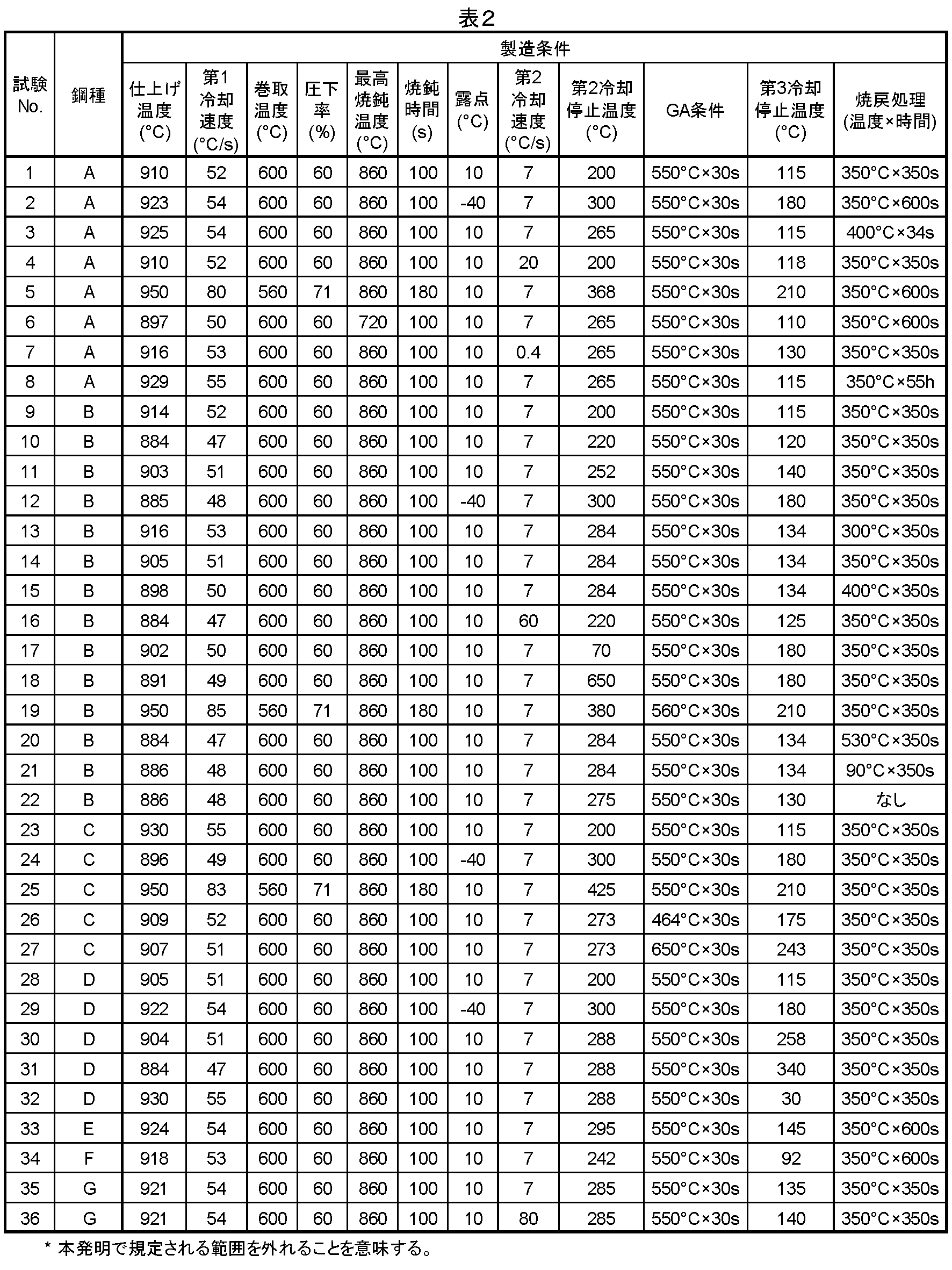
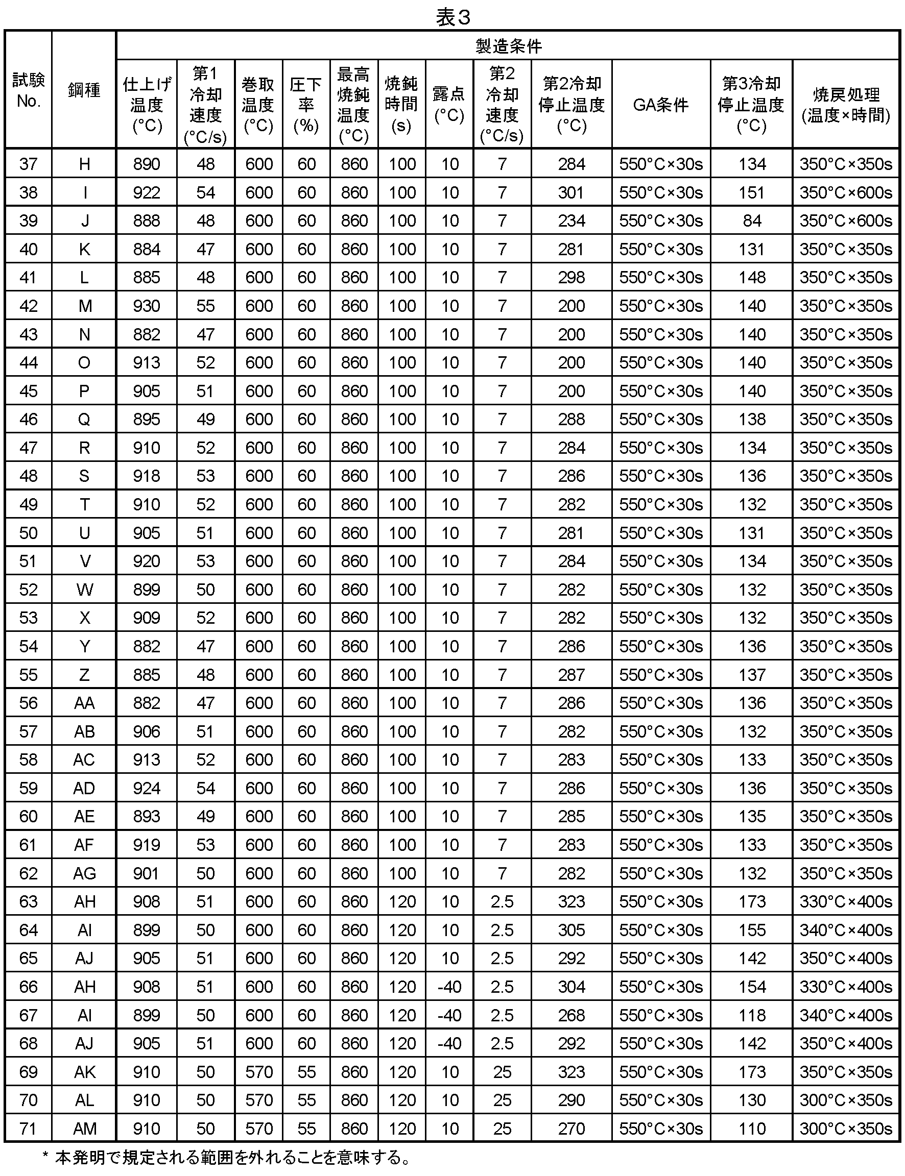
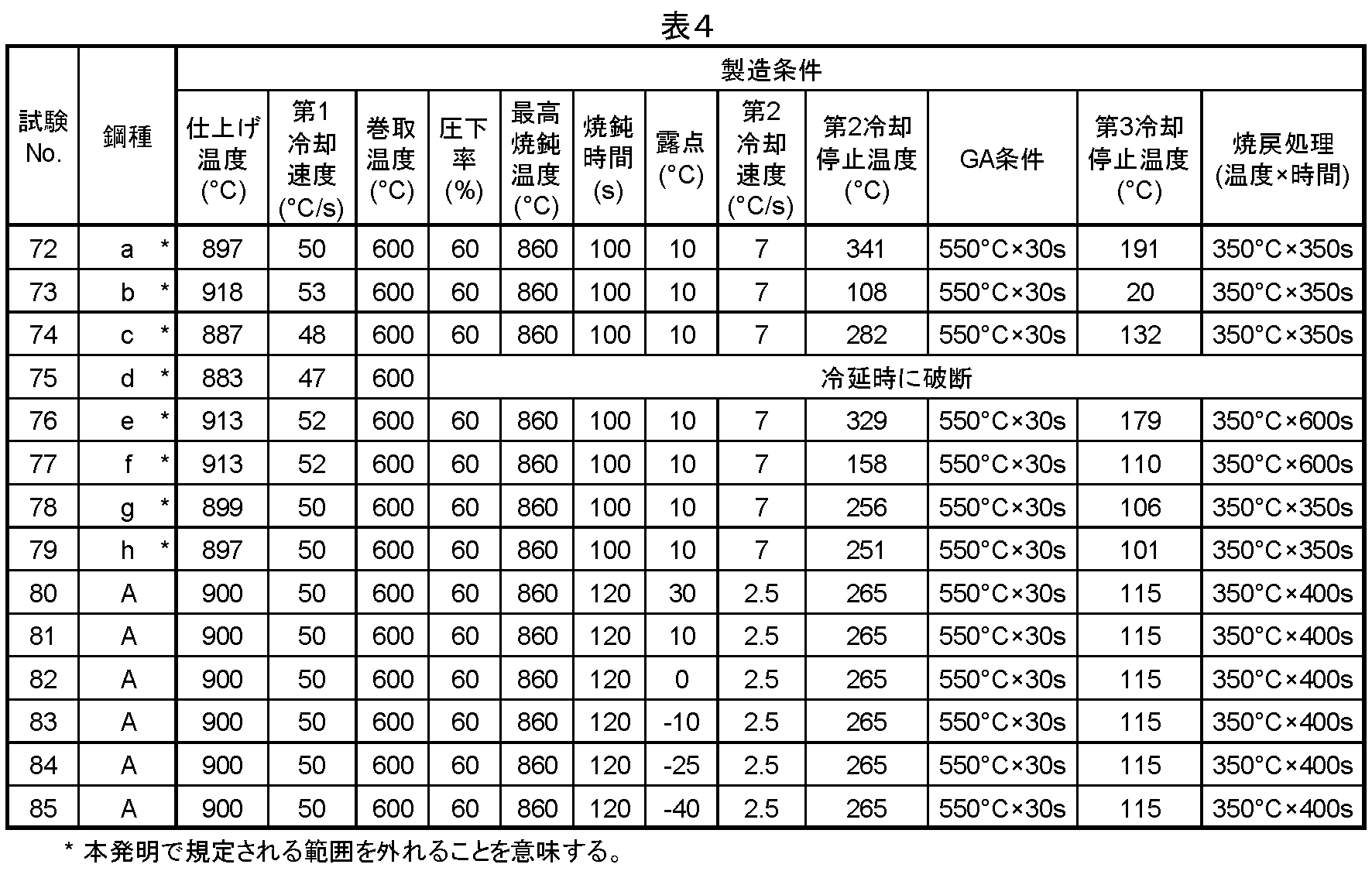
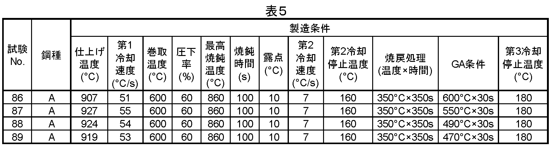
Vγ=(2/3){100/(0.7×α(111)/γ(200)+1)}
+(1/3){100/(0.78×α(211)/γ(311)+1)}
ただし、α(211)、γ(200)、α(211)、およびγ(311)は面強度を表す。
Cγ=(格子定数-3.572)/0.033
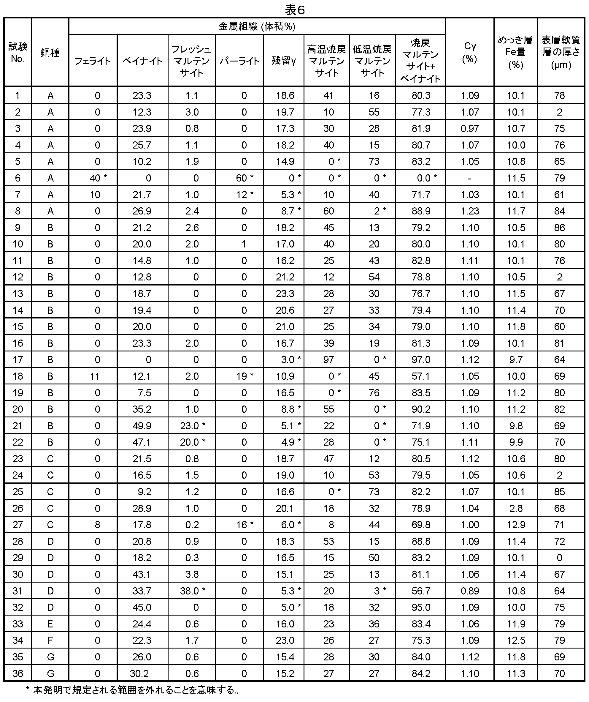
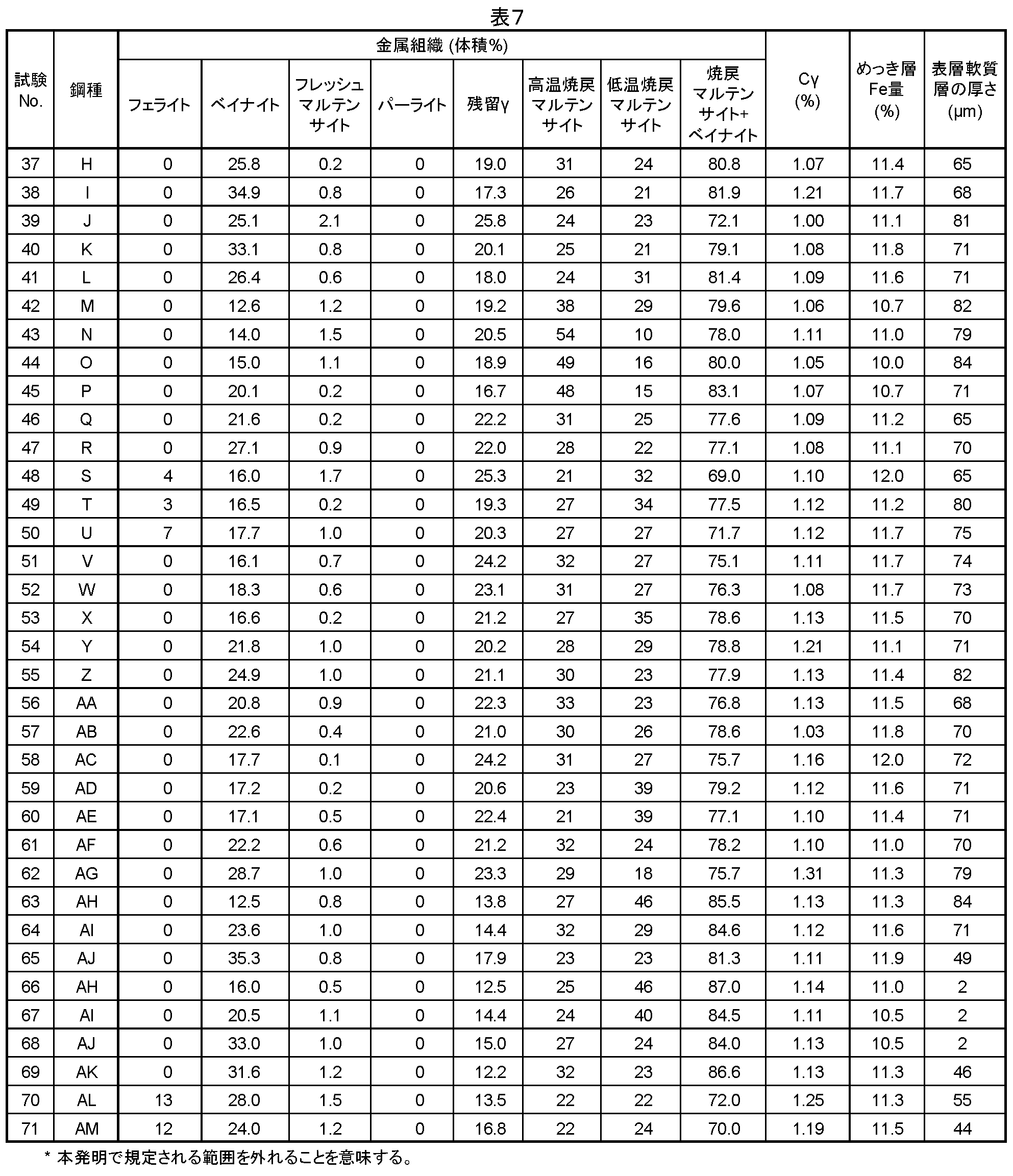

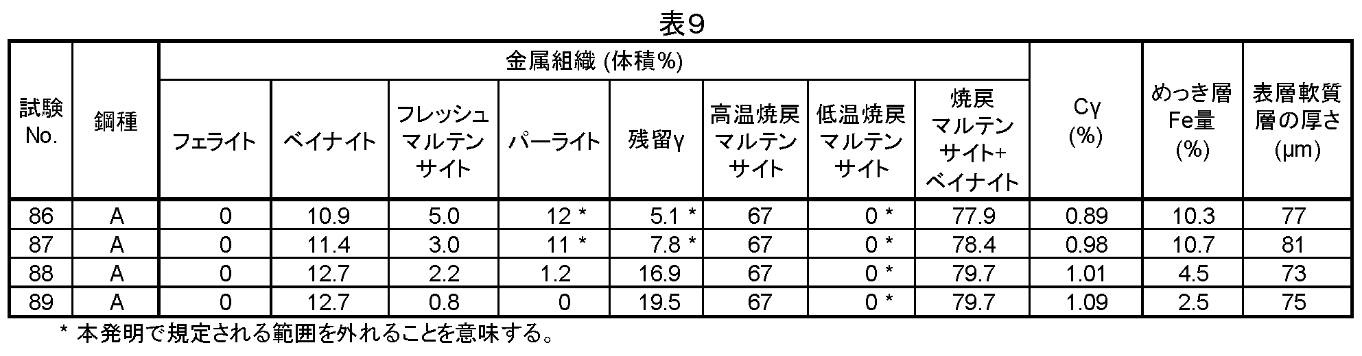
2:板組の内側に割れが生じているが、割れの長さが10μm以下である。
3:ナゲットにまで割れが進展している、または、ナゲットから300μm離れた位置の板組の外側に割れが生じている。
4:電極が接触した鋼板の表面部分とナゲットの間にだけ割れが生じている。
5:割れがない。
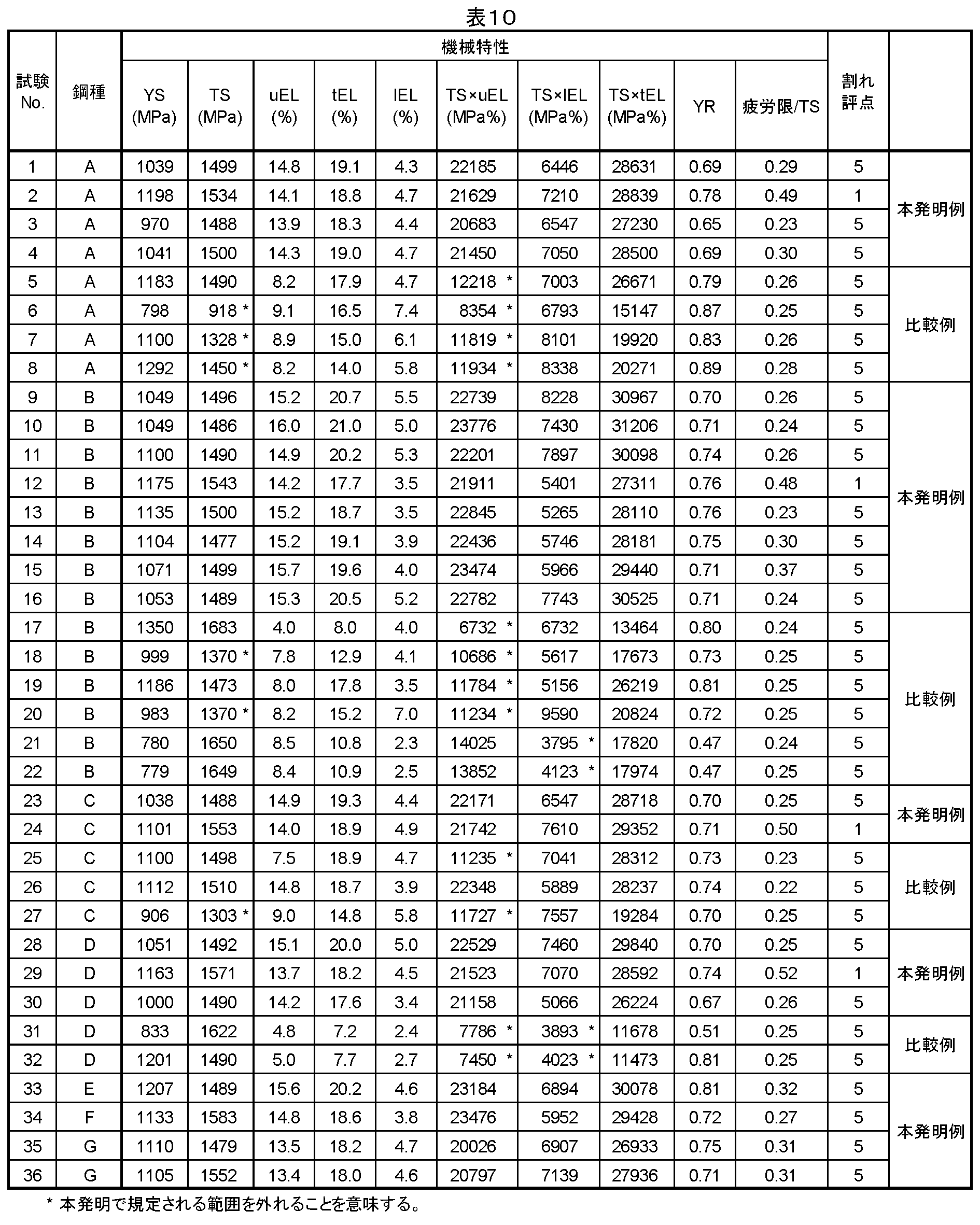
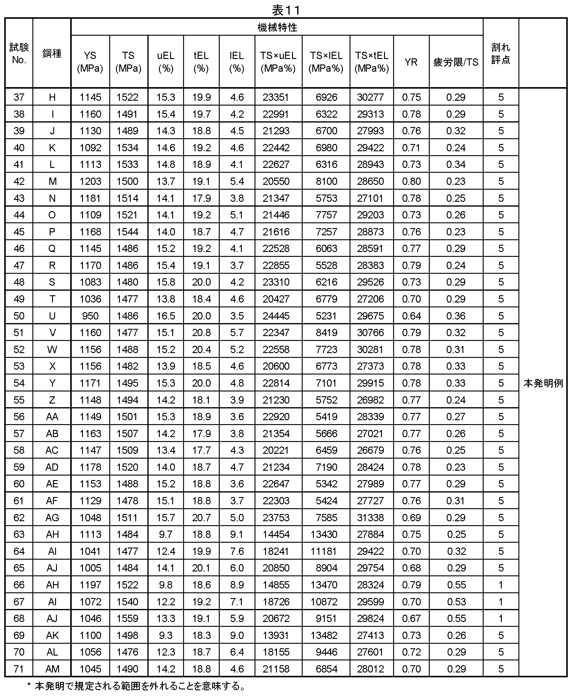
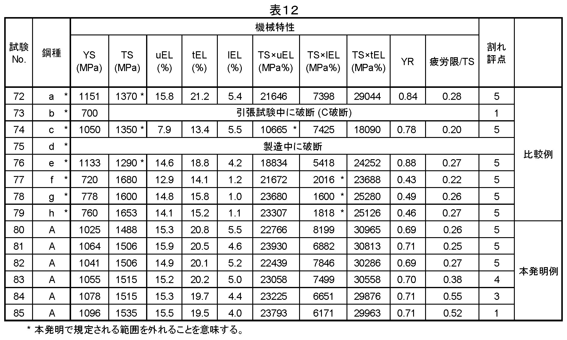

Claims (10)
- 鋼板の表面に合金化溶融亜鉛めっき層を備える合金化溶融亜鉛めっき鋼板であって、
前記鋼板の化学組成が、質量%で、
C:0.25~0.70%、
Si:0.25~2.50%、
Mn:1.00~5.00%、
Al:0.005~3.50%、
P:0.15%以下、
S:0.03%以下、
N:0.02%以下、
O:0.01%以下、
Ti:0~0.50%、
Nb:0~0.50%、
V:0~0.50%、
Cr:0~1.50%、
Mo:0~1.50%、
Cu:0~5.00%、
Ni:0~5.00%、
B:0~0.003%、
Ca:0~0.05%、
REM:0~0.05%、
Mg:0~0.05%、
W:0~0.50%、
Zr:0~0.05%、
Sb:0~0.50%、
Sn:0~0.50%、
As:0~0.05%、
Te:0~0.05%、
Y:0~0.20%、
Hf:0~0.20%、
Co:0~1.00%、
残部:Feおよび不純物であり、
前記鋼板の板厚1/4位置における金属組織が、体積%で、
残留オーステナイト:10.0~60.0%、
高温焼戻しマルテンサイト:5.0%以上、
低温焼戻しマルテンサイト:5.0%以上、
フレッシュマルテンサイト:10.0%以下、
フェライト:0~15.0%、
パーライト:0~10.0%、
残部:ベイナイトであり、
高温焼戻しマルテンサイトと低温焼戻しマルテンサイトとベイナイトとの合計体積率が30.0%以上であり、
引張強度が1470MPa以上、
引張強度と均一伸びとの積が13000MPa%以上、
引張強度と局部伸びとの積が5000MPa%以上である、
合金化溶融亜鉛めっき鋼板。 - 前記化学組成が、質量%で、
Si+Al:0.80%以上である、
請求項1に記載の合金化溶融亜鉛めっき鋼板。 - 前記化学組成が、質量%で、
Ti:0.005~0.50%、
Nb:0.005~0.50%、
V:0.005~0.50%、
Cr:0.01~1.50%、
Mo:0.01~1.50%、
Cu:0.01~5.00%、
Ni:0.01~5.00%、
B:0.0001~0.003%、
Ca:0.0001~0.05%、
REM:0.0005~0.05%、
Mg:0.0001~0.05%、
W:0.005~0.50%、
Zr:0.005~0.05%、
Sb:0.005~0.50%、
Sn:0.005~0.50%、
As:0.005~0.05%、
Te:0.001~0.05%、
Y:0.001~0.20%、
Hf:0.001~0.20%、および、
Co:0.001~1.00%、
から選択される1種以上を含有する、
請求項1または請求項2に記載の合金化溶融亜鉛めっき鋼板。 - 前記残留オーステナイトに含まれるC量が、0.85質量%以上である、
請求項1から請求項3までのいずれかに記載の合金化溶融亜鉛めっき鋼板。 - 前記合金化溶融亜鉛めっき層に含まれるFe量が、3.0~20.0質量%である、
請求項1から請求項4までのいずれかに記載の合金化溶融亜鉛めっき鋼板。 - 前記鋼板が表層に、板厚1/4位置から板厚1/2位置までの領域における平均硬さの0.9倍以下の硬さを有する表層軟質層を備え、
前記表層軟質層の、前記合金化溶融亜鉛めっき層と前記鋼板との界面からの厚さが、10μm超である、
請求項1から請求項5までのいずれかに記載の合金化溶融亜鉛めっき鋼板。 - 前記鋼板が表層に、板厚1/4位置から板厚1/2位置までの領域における平均硬さの0.9倍以下の硬さを有する表層軟質層を備え、
前記表層軟質層の、前記合金化溶融亜鉛めっき層と前記鋼板との界面からの厚さが、10μm以下であり、
前記鋼板の引張強度に対する疲労限の比が0.30以上である、
請求項1から請求項5までのいずれかに記載の合金化溶融亜鉛めっき鋼板。 - 請求項1から請求項5までのいずれかに記載の合金化溶融亜鉛めっき鋼板を製造する方法であって、
(a)上記(1)から(3)までのいずれかに記載の化学組成を有する鋼塊またはスラブを溶製する溶製工程、
(b)前記鋼塊またはスラブを加熱して熱間圧延を施し、熱延鋼板とする熱延工程、
(c)前記熱延鋼板を冷却する第1冷却工程、
(d)前記熱延鋼板を巻き取る巻取工程、
(e)前記熱延鋼板を巻き戻して、酸洗した後、冷間圧延を施し、冷延鋼板とする冷延工程、
(f)前記冷延鋼板をAc1点~920℃の温度域で5s以上保持する焼鈍工程、
(g)前記冷延鋼板を1℃/s以上の平均冷却速度で、100~600℃の温度域まで冷却する第2冷却工程、
(h)前記冷延鋼板を溶融亜鉛めっき浴温度まで冷却または加熱する前処理工程、
(i)前記冷延鋼板を溶融亜鉛めっき浴に浸漬して、鋼板に溶融亜鉛めっきを施し、溶融亜鉛めっき鋼板とするめっき工程、
(j)前記溶融亜鉛めっき鋼板を480~600℃に加熱し、溶融亜鉛めっきを合金化し、合金化溶融亜鉛めっき鋼板とする合金化工程、
(k)前記合金化溶融亜鉛めっき鋼板を1℃/s以上の平均冷却速度で、80~300℃の温度域まで冷却する第3冷却工程、および、
(l)前記合金化溶融亜鉛めっき鋼板を100~450℃の温度域で1s以上48h以下保持する焼戻工程、
を含み、上記(a)から(l)までの工程を順に行う、合金化溶融亜鉛めっき鋼板の製造方法。 - 請求項6に記載の合金化溶融亜鉛めっき鋼板を製造する方法であって、
(a)上記(1)から(3)までのいずれかに記載の化学組成を有する鋼塊またはスラブを溶製する溶製工程、
(b)前記鋼塊またはスラブを加熱して熱間圧延を施し、熱延鋼板とする熱延工程、
(c)前記熱延鋼板を冷却する第1冷却工程、
(d)前記熱延鋼板を巻き取る巻取工程、
(e)前記熱延鋼板を巻き戻して、酸洗した後、冷間圧延を施し、冷延鋼板とする冷延工程、
(f)前記冷延鋼板を、露点が-25℃以上の雰囲気において、Ac1点~920℃の温度域で5s以上保持する焼鈍工程、
(g)前記冷延鋼板を1℃/s以上の平均冷却速度で、100~600℃の温度域まで冷却する第2冷却工程、
(h)前記冷延鋼板を溶融亜鉛めっき浴温度まで冷却または加熱する前処理工程、
(i)前記冷延鋼板を溶融亜鉛めっき浴に浸漬して、鋼板に溶融亜鉛めっきを施し、溶融亜鉛めっき鋼板とするめっき工程、
(j)前記溶融亜鉛めっき鋼板を480~600℃に加熱し、溶融亜鉛めっきを合金化し、合金化溶融亜鉛めっき鋼板とする合金化工程、
(k)前記合金化溶融亜鉛めっき鋼板を1℃/s以上の平均冷却速度で、80~300℃の温度域まで冷却する第3冷却工程、および、
(l)前記合金化溶融亜鉛めっき鋼板を100~450℃の温度域で1s以上48h以下保持する焼戻工程、
を含み、上記(a)から(l)までの工程を順に行う、合金化溶融亜鉛めっき鋼板の製造方法。 - 請求項7に記載の合金化溶融亜鉛めっき鋼板を製造する方法であって、
(a)上記(1)から(3)までのいずれかに記載の化学組成を有する鋼塊またはスラブを溶製する溶製工程、
(b)前記鋼塊またはスラブを加熱して熱間圧延を施し、熱延鋼板とする熱延工程、
(c)前記熱延鋼板を冷却する第1冷却工程、
(d)前記熱延鋼板を巻き取る巻取工程、
(e)前記熱延鋼板を巻き戻して、酸洗した後、冷間圧延を施し、冷延鋼板とする冷延工程、
(f)前記冷延鋼板を、露点が-15℃以下の雰囲気において、Ac1点~920℃の温度域で5s以上保持する焼鈍工程、
(g)前記冷延鋼板を1℃/s以上の平均冷却速度で、100~600℃の温度域まで冷却する第2冷却工程、
(h)前記冷延鋼板を溶融亜鉛めっき浴温度まで冷却または加熱する前処理工程、
(i)前記冷延鋼板を溶融亜鉛めっき浴に浸漬して、鋼板に溶融亜鉛めっきを施し、溶融亜鉛めっき鋼板とするめっき工程、
(j)前記溶融亜鉛めっき鋼板を480~600℃に加熱し、溶融亜鉛めっきを合金化し、合金化溶融亜鉛めっき鋼板とする合金化工程、
(k)前記合金化溶融亜鉛めっき鋼板を1℃/s以上の平均冷却速度で、80~300℃の温度域まで冷却する第3冷却工程、および、
(l)前記合金化溶融亜鉛めっき鋼板を100~450℃の温度域で1s以上48h以下保持する焼戻工程、
を含み、上記(a)から(l)までの工程を順に行う、合金化溶融亜鉛めっき鋼板の製造方法。
Priority Applications (8)
| Application Number | Priority Date | Filing Date | Title |
|---|---|---|---|
| EP16807627.1A EP3309273B1 (en) | 2015-06-11 | 2016-06-10 | Galvannealed steel sheet and method for manufacturing same |
| CN201680034062.1A CN107636184A (zh) | 2015-06-11 | 2016-06-10 | 合金化热浸镀锌钢板及其制造方法 |
| US15/580,002 US10745775B2 (en) | 2015-06-11 | 2016-06-10 | Galvannealed steel sheet and method for producing the same |
| JP2016564653A JP6187710B2 (ja) | 2015-06-11 | 2016-06-10 | 合金化溶融亜鉛めっき鋼板およびその製造方法 |
| KR1020187000513A KR102081361B1 (ko) | 2015-06-11 | 2016-06-10 | 합금화 용융 아연 도금 강판 및 그 제조 방법 |
| MX2017015286A MX2017015286A (es) | 2015-06-11 | 2016-06-10 | Lamina de acero galvanizada y recocida y metodo para producirla. |
| BR112017025389-5A BR112017025389A2 (ja) | 2015-06-11 | 2016-06-10 | An alloying hot-dip zinc-coated carbon steel sheet and a manufacturing method for the same |
| CN202210520289.4A CN114990431A (zh) | 2015-06-11 | 2016-06-10 | 合金化热浸镀锌钢板及其制造方法 |
Applications Claiming Priority (6)
| Application Number | Priority Date | Filing Date | Title |
|---|---|---|---|
| JP2015-118648 | 2015-06-11 | ||
| JP2015118648 | 2015-06-11 | ||
| JP2015-137192 | 2015-07-08 | ||
| JP2015137052 | 2015-07-08 | ||
| JP2015-137052 | 2015-07-08 | ||
| JP2015137192 | 2015-07-08 |
Publications (1)
| Publication Number | Publication Date |
|---|---|
| WO2016199922A1 true WO2016199922A1 (ja) | 2016-12-15 |
Family
ID=57503465
Family Applications (1)
| Application Number | Title | Priority Date | Filing Date |
|---|---|---|---|
| PCT/JP2016/067448 Ceased WO2016199922A1 (ja) | 2015-06-11 | 2016-06-10 | 合金化溶融亜鉛めっき鋼板およびその製造方法 |
Country Status (9)
| Country | Link |
|---|---|
| US (1) | US10745775B2 (ja) |
| EP (1) | EP3309273B1 (ja) |
| JP (1) | JP6187710B2 (ja) |
| KR (1) | KR102081361B1 (ja) |
| CN (2) | CN107636184A (ja) |
| BR (1) | BR112017025389A2 (ja) |
| MX (1) | MX2017015286A (ja) |
| TW (1) | TWI602927B (ja) |
| WO (1) | WO2016199922A1 (ja) |
Cited By (32)
| Publication number | Priority date | Publication date | Assignee | Title |
|---|---|---|---|---|
| JP2017053001A (ja) * | 2015-09-09 | 2017-03-16 | 新日鐵住金株式会社 | 溶融亜鉛めっき鋼板および合金化溶融亜鉛めっき鋼板、並びにそれらの製造方法 |
| JP6213696B1 (ja) * | 2016-12-05 | 2017-10-18 | 新日鐵住金株式会社 | 高強度鋼板 |
| KR101858852B1 (ko) * | 2016-12-16 | 2018-06-28 | 주식회사 포스코 | 항복강도, 연성 및 구멍확장성이 우수한 고강도 냉연강판, 용융아연도금강판 및 이들의 제조방법 |
| WO2018131722A1 (ja) * | 2017-01-16 | 2018-07-19 | 新日鐵住金株式会社 | 鋼板及びその製造方法 |
| WO2018151322A1 (ja) * | 2017-02-20 | 2018-08-23 | 新日鐵住金株式会社 | 高強度鋼板 |
| WO2018151331A1 (ja) * | 2017-02-20 | 2018-08-23 | 新日鐵住金株式会社 | 高強度鋼板 |
| JP6421903B1 (ja) * | 2018-03-30 | 2018-11-14 | 新日鐵住金株式会社 | 溶融亜鉛めっき鋼板及び合金化溶融亜鉛めっき鋼板 |
| JP2019505678A (ja) * | 2015-12-29 | 2019-02-28 | アルセロールミタル | 超高強度合金化溶融亜鉛めっき鋼板を製造するための方法、及び得られた合金化溶融亜鉛めっき鋼板 |
| TWI671410B (zh) * | 2018-03-30 | 2019-09-11 | 日商日本製鐵股份有限公司 | 鋼板及其製造方法 |
| WO2019189842A1 (ja) * | 2018-03-30 | 2019-10-03 | Jfeスチール株式会社 | 高強度亜鉛めっき鋼板、高強度部材およびそれらの製造方法 |
| WO2019212045A1 (ja) * | 2018-05-01 | 2019-11-07 | 日本製鉄株式会社 | 亜鉛系めっき鋼板及びその製造方法 |
| JP6645637B1 (ja) * | 2018-08-22 | 2020-02-14 | Jfeスチール株式会社 | 高強度鋼板及びその製造方法 |
| WO2020039696A1 (ja) * | 2018-08-22 | 2020-02-27 | Jfeスチール株式会社 | 高強度鋼板及びその製造方法 |
| JP2020042004A (ja) * | 2018-09-10 | 2020-03-19 | 日本製鉄株式会社 | 析出物識別方法、析出物情報取得方法およびプログラム |
| WO2020080493A1 (ja) * | 2018-10-17 | 2020-04-23 | 日本製鉄株式会社 | 鋼板及び鋼板の製造方法 |
| JP2020128597A (ja) * | 2015-12-29 | 2020-08-27 | アルセロールミタル | 超高強度合金化溶融亜鉛めっき鋼板を製造するための方法、及び得られた合金化溶融亜鉛めっき鋼板 |
| EP3707283A1 (en) * | 2017-11-10 | 2020-09-16 | ArcelorMittal | Cold rolled heat treated steel sheet and a method of manufacturing thereof |
| CN111868282A (zh) * | 2018-07-18 | 2020-10-30 | 日本制铁株式会社 | 钢板 |
| EP3633058A4 (en) * | 2017-05-24 | 2020-12-02 | Kabushiki Kaisha Kobe Seiko Sho (Kobe Steel, Ltd.) | HIGH STRENGTH PLATED STEEL SHEET AND ITS MANUFACTURING PROCESS |
| JP2021500475A (ja) * | 2016-12-21 | 2021-01-07 | アルセロールミタル | 被覆鋼板の製造方法 |
| CN112281054A (zh) * | 2020-09-21 | 2021-01-29 | 中国石油天然气集团有限公司 | 一种SiMnNiMoV系中碳合金钢、钻机吊环及其制造方法 |
| WO2021141100A1 (ja) | 2020-01-09 | 2021-07-15 | 日本製鉄株式会社 | ホットスタンプ成形体 |
| WO2021141103A1 (ja) | 2020-01-09 | 2021-07-15 | 日本製鉄株式会社 | ホットスタンプ成形体 |
| WO2021141097A1 (ja) | 2020-01-09 | 2021-07-15 | 日本製鉄株式会社 | ホットスタンプ成形体 |
| JP2021123801A (ja) * | 2020-02-07 | 2021-08-30 | Jfeスチール株式会社 | 高強度鋼板およびその製造方法 |
| WO2021176285A1 (en) | 2020-03-02 | 2021-09-10 | Arcelormittal | High strength cold rolled and galvannealed steel sheet and manufacturing process thereof |
| CN113544296A (zh) * | 2019-03-20 | 2021-10-22 | 日本制铁株式会社 | 热冲压成形体 |
| US11332813B2 (en) * | 2018-04-05 | 2022-05-17 | Nippon Steel Corporation | Steel material suitable for use in sour environment |
| US11447842B2 (en) * | 2016-10-21 | 2022-09-20 | Hyundai Steel Company | High-strength reinforcing steel and method for manufacturing same |
| JP2023505444A (ja) * | 2019-12-03 | 2023-02-09 | ポスコホールディングス インコーポレーティッド | 表面品質及びスポット溶接性に優れた亜鉛めっき鋼板、並びにその製造方法 |
| JP2023505445A (ja) * | 2019-12-03 | 2023-02-09 | ポスコホールディングス インコーポレーティッド | 電気抵抗スポット溶接部の疲労強度に優れた亜鉛めっき鋼板、及びその製造方法 |
| JP2023542951A (ja) * | 2020-09-23 | 2023-10-12 | アルセロールミタル | 冷間圧延被覆鋼板及びその製造方法 |
Families Citing this family (48)
| Publication number | Priority date | Publication date | Assignee | Title |
|---|---|---|---|---|
| CN108603262B (zh) * | 2016-01-27 | 2020-03-20 | 杰富意钢铁株式会社 | 高屈服比型高强度镀锌钢板及其制造方法 |
| CN106244940A (zh) * | 2016-08-26 | 2016-12-21 | 天津新伟祥工业有限公司 | 一种铬锰氮系奥氏体耐热钢及其制备方法 |
| WO2018115946A1 (en) * | 2016-12-21 | 2018-06-28 | Arcelormittal | A method for the manufacture of a coated steel sheet |
| CN108300947A (zh) * | 2017-12-20 | 2018-07-20 | 柳州科瑞科技有限公司 | 一种高强度模具材料及其制备方法 |
| TW201938816A (zh) * | 2018-03-19 | 2019-10-01 | 日商新日鐵住金股份有限公司 | 高強度冷軋鋼板及其製造方法 |
| TWI650435B (zh) * | 2018-03-30 | 2019-02-11 | 日商新日鐵住金股份有限公司 | 鋼板及其製造方法 |
| CN108866437B (zh) * | 2018-07-06 | 2020-07-17 | 鞍钢股份有限公司 | 980MPa级轻质细晶的相变诱导塑性钢及其制备工艺 |
| TWI671409B (zh) * | 2018-08-28 | 2019-09-11 | 日商Jfe鋼鐵股份有限公司 | 鋼板及其製造方法 |
| KR102153197B1 (ko) * | 2018-12-18 | 2020-09-08 | 주식회사 포스코 | 가공성이 우수한 냉연강판, 용융아연도금강판 및 이들의 제조방법 |
| KR102276740B1 (ko) | 2018-12-18 | 2021-07-13 | 주식회사 포스코 | 연성 및 가공성이 우수한 고강도 강판 및 그 제조방법 |
| CN111471924A (zh) * | 2019-01-23 | 2020-07-31 | 山东卓远装饰材料有限公司 | 一种板材及其制备方法 |
| EP3922744B1 (en) * | 2019-02-06 | 2023-09-27 | Nippon Steel Corporation | Hot dip galvanized steel sheet and method for producing same |
| KR102464737B1 (ko) * | 2019-02-06 | 2022-11-10 | 닛폰세이테츠 가부시키가이샤 | 용융 아연 도금 강판 및 그의 제조 방법 |
| KR102321295B1 (ko) | 2019-12-18 | 2021-11-03 | 주식회사 포스코 | 가공성이 우수한 고강도 강판 및 그 제조방법 |
| KR102321292B1 (ko) | 2019-12-18 | 2021-11-03 | 주식회사 포스코 | 가공성이 우수한 고강도 강판 및 그 제조방법 |
| KR102321285B1 (ko) | 2019-12-18 | 2021-11-03 | 주식회사 포스코 | 가공성이 우수한 고강도 강판 및 그 제조방법 |
| KR102348527B1 (ko) | 2019-12-18 | 2022-01-07 | 주식회사 포스코 | 가공성이 우수한 고강도 강판 및 그 제조방법 |
| KR102748708B1 (ko) * | 2019-12-19 | 2025-01-06 | 닛폰세이테츠 가부시키가이샤 | 강판 및 그 제조 방법 |
| KR102348503B1 (ko) * | 2019-12-19 | 2022-01-06 | 주식회사 포스코 | 굽힘 특성이 우수한 강판 및 그 제조방법 |
| WO2021144804A1 (en) * | 2020-01-17 | 2021-07-22 | Indian Institute Of Technology Bombay | High strength and toughness low carbon nanostructured bainitic steel and preparation method thereof |
| CN114729432B (zh) * | 2020-03-16 | 2023-07-21 | 日本制铁株式会社 | 钢板 |
| MX2022011584A (es) * | 2020-03-17 | 2022-10-18 | Jfe Steel Corp | Lamina de acero de alta resistencia y metodo para producir la misma. |
| CN115362275B (zh) * | 2020-03-31 | 2024-03-01 | 杰富意钢铁株式会社 | 钢板、部件及其制造方法 |
| US12098439B2 (en) | 2020-03-31 | 2024-09-24 | Jfe Steel Corporation | Steel sheet, member, and method for producing them |
| JP7440799B2 (ja) * | 2020-06-08 | 2024-02-29 | 日本製鉄株式会社 | 鋼板及びその製造方法 |
| MX2022015468A (es) | 2020-06-08 | 2023-01-16 | Nippon Steel Corp | Lamina de acero y metodo para producir la misma. |
| CN111705267A (zh) * | 2020-06-30 | 2020-09-25 | 中铁宝桥集团有限公司 | 一种合金钢槽型护轨的制造方法 |
| KR102398151B1 (ko) * | 2020-09-07 | 2022-05-16 | 주식회사 포스코 | 연성이 우수한 초고강도 강판의 제조방법 및 이를 이용하여 제조된 초고강도 강판 |
| JP7417169B2 (ja) * | 2020-09-11 | 2024-01-18 | 日本製鉄株式会社 | 鋼板およびその製造方法 |
| CN112159931B (zh) * | 2020-09-28 | 2022-08-12 | 首钢集团有限公司 | 一种具有连续屈服的1000MPa级中锰TRIP钢及其制备方法 |
| KR102451003B1 (ko) * | 2020-12-18 | 2022-10-11 | 주식회사 포스코 | 도금밀착성 및 점용접성이 우수한 고강도 용융아연도금강판 및 그 제조방법 |
| CN112981243A (zh) * | 2021-02-03 | 2021-06-18 | 安徽绿能技术研究院有限公司 | 一种耐冲击合金铸钢及其制备方法 |
| JP7111281B1 (ja) | 2021-03-02 | 2022-08-02 | Jfeスチール株式会社 | 鋼板、部材およびそれらの製造方法 |
| WO2022185805A1 (ja) * | 2021-03-02 | 2022-09-09 | Jfeスチール株式会社 | 鋼板、部材およびそれらの製造方法 |
| WO2022185804A1 (ja) * | 2021-03-02 | 2022-09-09 | Jfeスチール株式会社 | 鋼板、部材およびそれらの製造方法 |
| JP7876505B2 (ja) | 2021-03-10 | 2026-06-19 | 日本製鉄株式会社 | 冷延鋼板及びその製造方法 |
| CN115181895B (zh) * | 2021-04-02 | 2023-09-12 | 宝山钢铁股份有限公司 | 1180MPa级别低碳低合金热镀锌Q&P钢及快速热处理热镀锌制造方法 |
| CN113416889B (zh) * | 2021-05-21 | 2022-07-22 | 鞍钢股份有限公司 | 焊接性能良好超高强热镀锌dh1470钢及制备方法 |
| CN113403529B (zh) * | 2021-05-21 | 2022-07-19 | 鞍钢股份有限公司 | 冷冲压用1470MPa级合金化镀锌钢板及其制备方法 |
| WO2022249650A1 (ja) * | 2021-05-26 | 2022-12-01 | Jfeスチール株式会社 | 自動車用部材およびその抵抗スポット溶接方法 |
| CN114150227B (zh) * | 2021-12-07 | 2022-11-18 | 武汉科技大学 | 用中薄板坯轧制Rm≥1500MPa高韧性热冲压钢及生产方法 |
| CN114990425B (zh) * | 2022-01-11 | 2023-07-18 | 长沙中金智能装备有限公司 | 一种废钢破碎用刀具及其制备、修复方法 |
| KR20240098869A (ko) * | 2022-12-21 | 2024-06-28 | 주식회사 포스코 | 굽힘성이 우수한 열간성형용 냉연강판, 열간성형부재 및 그들의 제조방법 |
| KR102918607B1 (ko) * | 2022-12-29 | 2026-01-29 | 현대제철 주식회사 | 내부식성 초고강도 냉연강판 및 그 제조방법 |
| CN119592878B (zh) * | 2023-09-11 | 2026-01-23 | 宝山钢铁股份有限公司 | 一种紧固件用盘条、低屈强比的超高强紧固件及其制造方法 |
| KR20250084345A (ko) * | 2023-12-01 | 2025-06-11 | 현대제철 주식회사 | 수소취성 저항성이 우수한 초고강도 냉연강판 및 그 제조방법 |
| KR102925633B1 (ko) * | 2023-12-01 | 2026-02-12 | 현대제철 주식회사 | 수소취성 저항성이 우수한 초고강도 냉연강판 및 그 제조방법 |
| KR20250093730A (ko) * | 2023-12-15 | 2025-06-25 | 주식회사 포스코 | 냉연강판 및 그 제조방법 |
Citations (2)
| Publication number | Priority date | Publication date | Assignee | Title |
|---|---|---|---|---|
| WO2013047755A1 (ja) * | 2011-09-30 | 2013-04-04 | 新日鐵住金株式会社 | 耐衝撃特性に優れた高強度溶融亜鉛めっき鋼板およびその製造方法、並びに、高強度合金化溶融亜鉛めっき鋼板およびその製造方法 |
| WO2013047830A1 (ja) * | 2011-09-30 | 2013-04-04 | 新日鐵住金株式会社 | 引張強度980MPa以上有するめっき密着性、成形性と穴広げ性に優れた高強度溶融亜鉛めっき鋼板及び高強度合金化溶融亜鉛めっき鋼板とその製造方法 |
Family Cites Families (11)
| Publication number | Priority date | Publication date | Assignee | Title |
|---|---|---|---|---|
| JP3527092B2 (ja) | 1998-03-27 | 2004-05-17 | 新日本製鐵株式会社 | 加工性の良い高強度合金化溶融亜鉛めっき鋼板とその製造方法 |
| JP5402007B2 (ja) * | 2008-02-08 | 2014-01-29 | Jfeスチール株式会社 | 加工性に優れた高強度溶融亜鉛めっき鋼板およびその製造方法 |
| JP2010065272A (ja) | 2008-09-10 | 2010-03-25 | Jfe Steel Corp | 高強度鋼板およびその製造方法 |
| JP5365112B2 (ja) * | 2008-09-10 | 2013-12-11 | Jfeスチール株式会社 | 高強度鋼板およびその製造方法 |
| JP5651964B2 (ja) | 2010-02-16 | 2015-01-14 | 新日鐵住金株式会社 | 延性及び穴広げ性並びに耐食性に優れた合金化溶融亜鉛めっき鋼板及びその製造方法 |
| KR101253885B1 (ko) | 2010-12-27 | 2013-04-16 | 주식회사 포스코 | 연성이 우수한 성형 부재용 강판, 성형 부재 및 그 제조방법 |
| PL2762600T3 (pl) * | 2011-09-30 | 2019-09-30 | Nippon Steel & Sumitomo Metal Corporation | Blacha stalowa cienka cynkowana zanurzeniowo na gorąco oraz sposób jej wytwarzania |
| TWI468534B (zh) | 2012-02-08 | 2015-01-11 | 新日鐵住金股份有限公司 | 高強度冷軋鋼板及其製造方法 |
| BR112015008396B1 (pt) | 2012-11-06 | 2019-12-03 | Nippon Steel Corporation | chapa de aço galvanizada por imersão a quente em liga e método de produção da mesma |
| JP6007882B2 (ja) * | 2013-10-15 | 2016-10-19 | 新日鐵住金株式会社 | 引張最大強度780MPaを有する衝突特性に優れた高強度鋼板、高強度溶融亜鉛めっき鋼板、並びに、高強度合金化溶融亜鉛めっき鋼板 |
| JP6007881B2 (ja) | 2013-10-15 | 2016-10-12 | 新日鐵住金株式会社 | 引張最大強度780MPa以上を有する衝突特性に優れた高強度鋼板、高強度溶融亜鉛めっき鋼板及び高強度合金化溶融亜鉛めっき鋼板 |
-
2016
- 2016-06-10 EP EP16807627.1A patent/EP3309273B1/en active Active
- 2016-06-10 MX MX2017015286A patent/MX2017015286A/es unknown
- 2016-06-10 BR BR112017025389-5A patent/BR112017025389A2/ja active Search and Examination
- 2016-06-10 CN CN201680034062.1A patent/CN107636184A/zh active Pending
- 2016-06-10 WO PCT/JP2016/067448 patent/WO2016199922A1/ja not_active Ceased
- 2016-06-10 CN CN202210520289.4A patent/CN114990431A/zh active Pending
- 2016-06-10 KR KR1020187000513A patent/KR102081361B1/ko active Active
- 2016-06-10 JP JP2016564653A patent/JP6187710B2/ja active Active
- 2016-06-10 US US15/580,002 patent/US10745775B2/en active Active
- 2016-06-13 TW TW105118877A patent/TWI602927B/zh not_active IP Right Cessation
Patent Citations (2)
| Publication number | Priority date | Publication date | Assignee | Title |
|---|---|---|---|---|
| WO2013047755A1 (ja) * | 2011-09-30 | 2013-04-04 | 新日鐵住金株式会社 | 耐衝撃特性に優れた高強度溶融亜鉛めっき鋼板およびその製造方法、並びに、高強度合金化溶融亜鉛めっき鋼板およびその製造方法 |
| WO2013047830A1 (ja) * | 2011-09-30 | 2013-04-04 | 新日鐵住金株式会社 | 引張強度980MPa以上有するめっき密着性、成形性と穴広げ性に優れた高強度溶融亜鉛めっき鋼板及び高強度合金化溶融亜鉛めっき鋼板とその製造方法 |
Cited By (78)
| Publication number | Priority date | Publication date | Assignee | Title |
|---|---|---|---|---|
| JP2017053001A (ja) * | 2015-09-09 | 2017-03-16 | 新日鐵住金株式会社 | 溶融亜鉛めっき鋼板および合金化溶融亜鉛めっき鋼板、並びにそれらの製造方法 |
| JP2020128597A (ja) * | 2015-12-29 | 2020-08-27 | アルセロールミタル | 超高強度合金化溶融亜鉛めっき鋼板を製造するための方法、及び得られた合金化溶融亜鉛めっき鋼板 |
| JP2019505678A (ja) * | 2015-12-29 | 2019-02-28 | アルセロールミタル | 超高強度合金化溶融亜鉛めっき鋼板を製造するための方法、及び得られた合金化溶融亜鉛めっき鋼板 |
| US11447842B2 (en) * | 2016-10-21 | 2022-09-20 | Hyundai Steel Company | High-strength reinforcing steel and method for manufacturing same |
| JP6213696B1 (ja) * | 2016-12-05 | 2017-10-18 | 新日鐵住金株式会社 | 高強度鋼板 |
| WO2018105003A1 (ja) * | 2016-12-05 | 2018-06-14 | 新日鐵住金株式会社 | 高強度鋼板 |
| KR101858852B1 (ko) * | 2016-12-16 | 2018-06-28 | 주식회사 포스코 | 항복강도, 연성 및 구멍확장성이 우수한 고강도 냉연강판, 용융아연도금강판 및 이들의 제조방법 |
| JP2021500475A (ja) * | 2016-12-21 | 2021-01-07 | アルセロールミタル | 被覆鋼板の製造方法 |
| WO2018131722A1 (ja) * | 2017-01-16 | 2018-07-19 | 新日鐵住金株式会社 | 鋼板及びその製造方法 |
| TWI666329B (zh) * | 2017-01-16 | 2019-07-21 | 日商新日鐵住金股份有限公司 | 鋼板及其製造方法 |
| JPWO2018131722A1 (ja) * | 2017-01-16 | 2019-11-07 | 日本製鉄株式会社 | 鋼板及びその製造方法 |
| US11261505B2 (en) | 2017-02-20 | 2022-03-01 | Nippon Steel Corporation | High strength steel sheet |
| US11408046B2 (en) | 2017-02-20 | 2022-08-09 | Nippon Steel Corporation | High strength steel sheet |
| WO2018151331A1 (ja) * | 2017-02-20 | 2018-08-23 | 新日鐵住金株式会社 | 高強度鋼板 |
| WO2018151322A1 (ja) * | 2017-02-20 | 2018-08-23 | 新日鐵住金株式会社 | 高強度鋼板 |
| EP3633058A4 (en) * | 2017-05-24 | 2020-12-02 | Kabushiki Kaisha Kobe Seiko Sho (Kobe Steel, Ltd.) | HIGH STRENGTH PLATED STEEL SHEET AND ITS MANUFACTURING PROCESS |
| JP2023011852A (ja) * | 2017-11-10 | 2023-01-24 | アルセロールミタル | 冷間圧延熱処理鋼板及びその製造方法 |
| US11572599B2 (en) | 2017-11-10 | 2023-02-07 | Arcelormittal | Cold rolled heat treated steel sheet and a method of manufacturing thereof |
| JP2025013954A (ja) * | 2017-11-10 | 2025-01-28 | アルセロールミタル | 冷間圧延熱処理鋼板及びその製造方法 |
| US12338506B2 (en) | 2017-11-10 | 2025-06-24 | Arcelormittal | Cold rolled heat treated steel sheet and a method of manufacturing thereof |
| JP2021502486A (ja) * | 2017-11-10 | 2021-01-28 | アルセロールミタル | 冷間圧延熱処理鋼板及びその製造方法 |
| EP3707283A1 (en) * | 2017-11-10 | 2020-09-16 | ArcelorMittal | Cold rolled heat treated steel sheet and a method of manufacturing thereof |
| JP6631760B1 (ja) * | 2018-03-30 | 2020-01-15 | Jfeスチール株式会社 | 高強度亜鉛めっき鋼板および高強度部材 |
| JP2020045568A (ja) * | 2018-03-30 | 2020-03-26 | Jfeスチール株式会社 | 高強度亜鉛めっき鋼板の製造方法、及び高強度部材の製造方法 |
| US11795531B2 (en) | 2018-03-30 | 2023-10-24 | Jfe Steel Corporation | High-strength galvanized steel sheet, high strength member, and method for manufacturing the same |
| JP6421903B1 (ja) * | 2018-03-30 | 2018-11-14 | 新日鐵住金株式会社 | 溶融亜鉛めっき鋼板及び合金化溶融亜鉛めっき鋼板 |
| TWI671410B (zh) * | 2018-03-30 | 2019-09-11 | 日商日本製鐵股份有限公司 | 鋼板及其製造方法 |
| WO2019187124A1 (ja) * | 2018-03-30 | 2019-10-03 | 日本製鉄株式会社 | 溶融亜鉛めっき鋼板及び合金化溶融亜鉛めっき鋼板 |
| WO2019189842A1 (ja) * | 2018-03-30 | 2019-10-03 | Jfeスチール株式会社 | 高強度亜鉛めっき鋼板、高強度部材およびそれらの製造方法 |
| US11332813B2 (en) * | 2018-04-05 | 2022-05-17 | Nippon Steel Corporation | Steel material suitable for use in sour environment |
| JP6631765B1 (ja) * | 2018-05-01 | 2020-01-15 | 日本製鉄株式会社 | 亜鉛系めっき鋼板及びその製造方法 |
| US11859259B2 (en) | 2018-05-01 | 2024-01-02 | Nippon Steel Corporation | Zinc-plated steel sheet and manufacturing method thereof |
| CN112041475A (zh) * | 2018-05-01 | 2020-12-04 | 日本制铁株式会社 | 镀锌钢板及其制造方法 |
| WO2019212045A1 (ja) * | 2018-05-01 | 2019-11-07 | 日本製鉄株式会社 | 亜鉛系めっき鋼板及びその製造方法 |
| CN112041475B (zh) * | 2018-05-01 | 2021-09-17 | 日本制铁株式会社 | 镀锌钢板及其制造方法 |
| CN111868282B (zh) * | 2018-07-18 | 2021-12-31 | 日本制铁株式会社 | 钢板 |
| CN111868282A (zh) * | 2018-07-18 | 2020-10-30 | 日本制铁株式会社 | 钢板 |
| WO2020039697A1 (ja) * | 2018-08-22 | 2020-02-27 | Jfeスチール株式会社 | 高強度鋼板及びその製造方法 |
| WO2020039696A1 (ja) * | 2018-08-22 | 2020-02-27 | Jfeスチール株式会社 | 高強度鋼板及びその製造方法 |
| JP6683297B1 (ja) * | 2018-08-22 | 2020-04-15 | Jfeスチール株式会社 | 高強度鋼板及びその製造方法 |
| US11846002B2 (en) | 2018-08-22 | 2023-12-19 | Jfe Steel Corporation | High-strength steel sheet and method for manufacturing same |
| US11898230B2 (en) | 2018-08-22 | 2024-02-13 | Jfe Steel Corporation | High-strength steel sheet and method for manufacturing same |
| JP6645637B1 (ja) * | 2018-08-22 | 2020-02-14 | Jfeスチール株式会社 | 高強度鋼板及びその製造方法 |
| JP7277729B2 (ja) | 2018-09-10 | 2023-05-19 | 日本製鉄株式会社 | 析出物識別方法、析出物情報取得方法およびプログラム |
| JP2020042004A (ja) * | 2018-09-10 | 2020-03-19 | 日本製鉄株式会社 | 析出物識別方法、析出物情報取得方法およびプログラム |
| WO2020080493A1 (ja) * | 2018-10-17 | 2020-04-23 | 日本製鉄株式会社 | 鋼板及び鋼板の製造方法 |
| JP6760543B1 (ja) * | 2018-10-17 | 2020-09-23 | 日本製鉄株式会社 | 鋼板及び鋼板の製造方法 |
| CN113544296B (zh) * | 2019-03-20 | 2023-01-10 | 日本制铁株式会社 | 热冲压成形体 |
| CN113544296A (zh) * | 2019-03-20 | 2021-10-22 | 日本制铁株式会社 | 热冲压成形体 |
| US12054801B2 (en) | 2019-12-03 | 2024-08-06 | Posco | Zinc plated steel sheet having excellent surface quality and spot weldability, and manufacturing method therefor |
| JP7585324B2 (ja) | 2019-12-03 | 2024-11-18 | ポスコホールディングス インコーポレーティッド | 表面品質及びスポット溶接性に優れた亜鉛めっき鋼板、並びにその製造方法 |
| JP2024138313A (ja) * | 2019-12-03 | 2024-10-08 | ポスコホールディングス インコーポレーティッド | 表面品質及びスポット溶接性に優れた亜鉛めっき鋼板、並びにその製造方法 |
| JP2023505444A (ja) * | 2019-12-03 | 2023-02-09 | ポスコホールディングス インコーポレーティッド | 表面品質及びスポット溶接性に優れた亜鉛めっき鋼板、並びにその製造方法 |
| US12630896B2 (en) | 2019-12-03 | 2026-05-19 | Posco | Zinc plated steel sheet having excellent surface quality and spot weldability, and manufacturing method therefor |
| JP7845759B2 (ja) | 2019-12-03 | 2026-04-14 | ポスコホールディングス インコーポレーティッド | 表面品質及びスポット溶接性に優れた亜鉛めっき鋼板、並びにその製造方法 |
| JP2024138314A (ja) * | 2019-12-03 | 2024-10-08 | ポスコホールディングス インコーポレーティッド | 電気抵抗スポット溶接部の疲労強度に優れた亜鉛めっき鋼板、及びその製造方法 |
| US12486553B2 (en) | 2019-12-03 | 2025-12-02 | Posco | Zinc plated steel sheet having excellent fatigue strength of electrical resistance spot welds, and manufacturing method thereof |
| US11981973B2 (en) | 2019-12-03 | 2024-05-14 | Posco | Zinc plated steel sheet having excellent fatigue strength of electrical resistance spot welds, and manufacturing method thereof |
| JP7585325B2 (ja) | 2019-12-03 | 2024-11-18 | ポスコホールディングス インコーポレーティッド | 電気抵抗スポット溶接部の疲労強度に優れた亜鉛めっき鋼板、及びその製造方法 |
| JP2023505445A (ja) * | 2019-12-03 | 2023-02-09 | ポスコホールディングス インコーポレーティッド | 電気抵抗スポット溶接部の疲労強度に優れた亜鉛めっき鋼板、及びその製造方法 |
| JP7845623B2 (ja) | 2019-12-03 | 2026-04-14 | ポスコホールディングス インコーポレーティッド | 電気抵抗スポット溶接部の疲労強度に優れた亜鉛めっき鋼板、及びその製造方法 |
| EP4089193A4 (en) * | 2020-01-09 | 2023-07-26 | Nippon Steel Corporation | HOT STAMPING MOLDED BODY |
| US12358036B2 (en) | 2020-01-09 | 2025-07-15 | Nippon Steel Corporation | Hot-stamping formed body |
| WO2021141100A1 (ja) | 2020-01-09 | 2021-07-15 | 日本製鉄株式会社 | ホットスタンプ成形体 |
| KR20220092945A (ko) | 2020-01-09 | 2022-07-04 | 닛폰세이테츠 가부시키가이샤 | 핫 스탬프 성형체 |
| KR20220091571A (ko) | 2020-01-09 | 2022-06-30 | 닛폰세이테츠 가부시키가이샤 | 핫 스탬프 성형체 |
| KR20220091572A (ko) | 2020-01-09 | 2022-06-30 | 닛폰세이테츠 가부시키가이샤 | 핫 스탬프 성형체 |
| WO2021141103A1 (ja) | 2020-01-09 | 2021-07-15 | 日本製鉄株式会社 | ホットスタンプ成形体 |
| WO2021141097A1 (ja) | 2020-01-09 | 2021-07-15 | 日本製鉄株式会社 | ホットスタンプ成形体 |
| US12410498B2 (en) | 2020-01-09 | 2025-09-09 | Nippon Steel Corporation | Hot-stamping formed body |
| US12392017B2 (en) | 2020-01-09 | 2025-08-19 | Nippon Steel Corporation | Hot-stamping formed body |
| JP2021123801A (ja) * | 2020-02-07 | 2021-08-30 | Jfeスチール株式会社 | 高強度鋼板およびその製造方法 |
| JP7276366B2 (ja) | 2020-02-07 | 2023-05-18 | Jfeスチール株式会社 | 高強度鋼板およびその製造方法 |
| WO2021176285A1 (en) | 2020-03-02 | 2021-09-10 | Arcelormittal | High strength cold rolled and galvannealed steel sheet and manufacturing process thereof |
| WO2021176249A1 (en) | 2020-03-02 | 2021-09-10 | Arcelormittal | High strength cold rolled and galvannealed steel sheet and manufacturing process thereof |
| CN112281054A (zh) * | 2020-09-21 | 2021-01-29 | 中国石油天然气集团有限公司 | 一种SiMnNiMoV系中碳合金钢、钻机吊环及其制造方法 |
| JP2025111554A (ja) * | 2020-09-23 | 2025-07-30 | アルセロールミタル | 冷間圧延被覆鋼板及びその製造方法 |
| JP2023542951A (ja) * | 2020-09-23 | 2023-10-12 | アルセロールミタル | 冷間圧延被覆鋼板及びその製造方法 |
Also Published As
| Publication number | Publication date |
|---|---|
| BR112017025389A2 (ja) | 2018-08-07 |
| TW201713778A (zh) | 2017-04-16 |
| JPWO2016199922A1 (ja) | 2017-06-22 |
| US20180298462A1 (en) | 2018-10-18 |
| CN107636184A (zh) | 2018-01-26 |
| KR20180016518A (ko) | 2018-02-14 |
| EP3309273B1 (en) | 2021-05-26 |
| KR102081361B1 (ko) | 2020-02-25 |
| US10745775B2 (en) | 2020-08-18 |
| JP6187710B2 (ja) | 2017-08-30 |
| EP3309273A1 (en) | 2018-04-18 |
| TWI602927B (zh) | 2017-10-21 |
| CN114990431A (zh) | 2022-09-02 |
| EP3309273A4 (en) | 2018-12-26 |
| MX2017015286A (es) | 2018-02-19 |
Similar Documents
| Publication | Publication Date | Title |
|---|---|---|
| JP6187710B2 (ja) | 合金化溶融亜鉛めっき鋼板およびその製造方法 | |
| JP6525114B1 (ja) | 高強度亜鉛めっき鋼板およびその製造方法 | |
| JP6620474B2 (ja) | 溶融亜鉛めっき鋼板および合金化溶融亜鉛めっき鋼板、並びにそれらの製造方法 | |
| JP6354075B1 (ja) | 高強度薄鋼板およびその製造方法 | |
| JP6787535B1 (ja) | 高強度鋼板およびその製造方法 | |
| JP5418047B2 (ja) | 高強度鋼板およびその製造方法 | |
| JP5454745B2 (ja) | 高強度鋼板およびその製造方法 | |
| KR101411783B1 (ko) | 고강도 강판 및 그 제조 방법 | |
| JP5403185B2 (ja) | 引張強度980MPa以上有するめっき密着性、成形性と穴広げ性に優れた高強度溶融亜鉛めっき鋼板及び高強度合金化溶融亜鉛めっき鋼板とその製造方法 | |
| RU2566121C1 (ru) | Высокопрочный гальванизированный погружением стальной лист с превосходной характеристикой сопротивления удару и способ его изготовления и высокопрочный, подвергнутый легированию, гальванизированный погружением стальной лист и способ его изготовления | |
| CN113166865B (zh) | 成形性、韧性及焊接性优异的高强度钢板及其制造方法 | |
| WO2020162556A1 (ja) | 溶融亜鉛めっき鋼板およびその製造方法 | |
| WO2020162560A1 (ja) | 溶融亜鉛めっき鋼板およびその製造方法 | |
| JP7364933B2 (ja) | 鋼板及びその製造方法 | |
| JP2017002384A (ja) | 耐スポット溶接部破断特性に優れた鋼板及びその製造方法 | |
| JPWO2015093043A1 (ja) | 高強度溶融亜鉛めっき鋼板及びその製造方法 | |
| JP2017048412A (ja) | 溶融亜鉛めっき鋼板、合金化溶融亜鉛めっき鋼板、およびそれらの製造方法 | |
| JP5741456B2 (ja) | 合金化溶融亜鉛めっき鋼板およびその製造方法 | |
| EP2757169A1 (en) | High-strength steel sheet having excellent workability and method for producing same | |
| JP6750771B1 (ja) | 溶融亜鉛めっき鋼板およびその製造方法 | |
| JP5239562B2 (ja) | 加工性に優れる高強度溶融亜鉛めっき鋼板およびその製造方法 | |
| US20130048155A1 (en) | High-strength galvanized steel sheet having excellent formability and spot weldability and method for manufacturing the same | |
| US11186889B2 (en) | High-strength steel sheet and manufacturing method therefor | |
| JP7311808B2 (ja) | 鋼板及びその製造方法 | |
| CN115210398B (zh) | 钢板、构件和它们的制造方法 |
Legal Events
| Date | Code | Title | Description |
|---|---|---|---|
| ENP | Entry into the national phase |
Ref document number: 2016564653 Country of ref document: JP Kind code of ref document: A |
|
| 121 | Ep: the epo has been informed by wipo that ep was designated in this application |
Ref document number: 16807627 Country of ref document: EP Kind code of ref document: A1 |
|
| WWE | Wipo information: entry into national phase |
Ref document number: MX/A/2017/015286 Country of ref document: MX |
|
| WWE | Wipo information: entry into national phase |
Ref document number: 15580002 Country of ref document: US |
|
| NENP | Non-entry into the national phase |
Ref country code: DE |
|
| ENP | Entry into the national phase |
Ref document number: 20187000513 Country of ref document: KR Kind code of ref document: A |
|
| WWE | Wipo information: entry into national phase |
Ref document number: 2016807627 Country of ref document: EP |
|
| REG | Reference to national code |
Ref country code: BR Ref legal event code: B01A Ref document number: 112017025389 Country of ref document: BR |
|
| ENP | Entry into the national phase |
Ref document number: 112017025389 Country of ref document: BR Kind code of ref document: A2 Effective date: 20171127 |