WO2016199612A1 - ガラス板の製造方法、ガラス板、および表示装置 - Google Patents
ガラス板の製造方法、ガラス板、および表示装置 Download PDFInfo
- Publication number
- WO2016199612A1 WO2016199612A1 PCT/JP2016/065920 JP2016065920W WO2016199612A1 WO 2016199612 A1 WO2016199612 A1 WO 2016199612A1 JP 2016065920 W JP2016065920 W JP 2016065920W WO 2016199612 A1 WO2016199612 A1 WO 2016199612A1
- Authority
- WO
- WIPO (PCT)
- Prior art keywords
- glass plate
- curved surface
- polishing
- glass
- max
- Prior art date
- Legal status (The legal status is an assumption and is not a legal conclusion. Google has not performed a legal analysis and makes no representation as to the accuracy of the status listed.)
- Ceased
Links
Images



Classifications
-
- B—PERFORMING OPERATIONS; TRANSPORTING
- B24—GRINDING; POLISHING
- B24B—MACHINES, DEVICES, OR PROCESSES FOR GRINDING OR POLISHING; DRESSING OR CONDITIONING OF ABRADING SURFACES; FEEDING OF GRINDING, POLISHING, OR LAPPING AGENTS
- B24B13/00—Machines or devices designed for grinding or polishing optical surfaces on lenses or surfaces of similar shape on other work; Accessories therefor
- B24B13/01—Specific tools, e.g. bowl-like; Production, dressing or fastening of these tools
-
- B—PERFORMING OPERATIONS; TRANSPORTING
- B24—GRINDING; POLISHING
- B24B—MACHINES, DEVICES, OR PROCESSES FOR GRINDING OR POLISHING; DRESSING OR CONDITIONING OF ABRADING SURFACES; FEEDING OF GRINDING, POLISHING, OR LAPPING AGENTS
- B24B29/00—Machines or devices for polishing surfaces on work by means of tools made of soft or flexible material with or without the application of solid or liquid polishing agents
- B24B29/005—Machines or devices for polishing surfaces on work by means of tools made of soft or flexible material with or without the application of solid or liquid polishing agents using brushes
-
- B—PERFORMING OPERATIONS; TRANSPORTING
- B24—GRINDING; POLISHING
- B24B—MACHINES, DEVICES, OR PROCESSES FOR GRINDING OR POLISHING; DRESSING OR CONDITIONING OF ABRADING SURFACES; FEEDING OF GRINDING, POLISHING, OR LAPPING AGENTS
- B24B7/00—Machines or devices designed for grinding plane surfaces on work, including polishing plane glass surfaces; Accessories therefor
- B24B7/20—Machines or devices designed for grinding plane surfaces on work, including polishing plane glass surfaces; Accessories therefor characterised by a special design with respect to properties of the material of non-metallic articles to be ground
- B24B7/22—Machines or devices designed for grinding plane surfaces on work, including polishing plane glass surfaces; Accessories therefor characterised by a special design with respect to properties of the material of non-metallic articles to be ground for grinding inorganic material, e.g. stone, ceramics, porcelain
- B24B7/24—Machines or devices designed for grinding plane surfaces on work, including polishing plane glass surfaces; Accessories therefor characterised by a special design with respect to properties of the material of non-metallic articles to be ground for grinding inorganic material, e.g. stone, ceramics, porcelain for grinding or polishing glass
- B24B7/242—Machines or devices designed for grinding plane surfaces on work, including polishing plane glass surfaces; Accessories therefor characterised by a special design with respect to properties of the material of non-metallic articles to be ground for grinding inorganic material, e.g. stone, ceramics, porcelain for grinding or polishing glass for plate glass
-
- C—CHEMISTRY; METALLURGY
- C03—GLASS; MINERAL OR SLAG WOOL
- C03C—CHEMICAL COMPOSITION OF GLASSES, GLAZES OR VITREOUS ENAMELS; SURFACE TREATMENT OF GLASS; SURFACE TREATMENT OF FIBRES OR FILAMENTS MADE FROM GLASS, MINERALS OR SLAGS; JOINING GLASS TO GLASS OR OTHER MATERIALS
- C03C19/00—Surface treatment of glass, not in the form of fibres or filaments, by mechanical means
-
- C—CHEMISTRY; METALLURGY
- C03—GLASS; MINERAL OR SLAG WOOL
- C03C—CHEMICAL COMPOSITION OF GLASSES, GLAZES OR VITREOUS ENAMELS; SURFACE TREATMENT OF GLASS; SURFACE TREATMENT OF FIBRES OR FILAMENTS MADE FROM GLASS, MINERALS OR SLAGS; JOINING GLASS TO GLASS OR OTHER MATERIALS
- C03C21/00—Treatment of glass, not in the form of fibres or filaments, by diffusing ions or metals in the surface
- C03C21/001—Treatment of glass, not in the form of fibres or filaments, by diffusing ions or metals in the surface in liquid phase, e.g. molten salts, solutions
- C03C21/002—Treatment of glass, not in the form of fibres or filaments, by diffusing ions or metals in the surface in liquid phase, e.g. molten salts, solutions to perform ion-exchange between alkali ions
Definitions
- the present invention relates to a glass plate manufacturing method, a glass plate, and a display device.
- Patent Document 1 describes a technique of polishing a curved surface of a glass plate with a rubber sleeve.
- the rubber sleeve is a rubber hollow cylinder, and is used while supplying air to the inside and maintaining a constant internal pressure.
- the rubber sleeve is elastically deformed so as to be in close contact with the curved surface of the glass plate during polishing.
- Patent Document 2 describes a technique for polishing a curved surface of a glass plate with a rotating drum.
- the curved surface of the glass plate can be polished by changing the position of the center of the rotating drum with respect to the center of the glass plate according to the rotation angle of the glass plate.
- Patent Document 3 describes a technique for polishing a curved surface of a glass plate with a polishing pad.
- the polishing pad has a plurality of elastic members inside and is elastically deformed so as to be in close contact with the curved surface of the glass plate during polishing.
- polishing the curved surface of a glass plate polishing with a rubber sleeve, a rotating drum, a polishing pad, etc. has a slow polishing rate and takes a long time to remove large defects.
- the present invention has been made in view of the above problems, and has as its main object to provide a method for producing a glass plate, which can remove a major defect of the glass plate in a short time.
- a method for producing a glass plate comprising a polishing step of polishing the curved surface of the glass plate with a polishing tool
- the polishing tool is a rotary brush, and has a rotary core and brush hair provided on an outer peripheral portion of the rotary core,
- the brush hair has an average diameter of 300 ⁇ m or less
- the relative position of the rotating brush with respect to the glass plate is swung in the axial direction of the rotating brush,
- the swing speed is 1 mm / sec or more and the swing amplitude is 0.5 mm or more.
- a method for producing a glass plate that can remove a major defect of the glass plate in a short time.
- FIG. 2 is a cross-sectional view taken along line II-II in FIG. It is a figure which shows the glass plate after grinding
- FIG. It is a figure which shows the manufacturing method of the glass plate by the comparative example 2.
- FIG. It is a figure which shows the edge part of the glass plate after grinding
- FIG. 1 is a cross-sectional view illustrating a glass plate manufacturing method according to an embodiment.
- the movement trajectory of the center line of the rotating brush 20 is indicated by a two-dot chain line.
- FIG. 2 is a sectional view taken along line II-II in FIG. 1 and 2, the X direction, the Y direction, and the Z direction are directions perpendicular to each other.
- the X direction represents the axial direction of the rotary brush 20
- the Z direction represents the up-down direction
- the Y direction represents a direction perpendicular to the X direction and the Z direction.
- the glass plate manufacturing method has a polishing step of polishing the curved surface 11 of the glass plate 10 with a rotating brush 20 as a polishing tool.
- the glass plate 10 may be for in-vehicle use or display use, for example.
- the display may be any of a cathode ray tube, a liquid crystal display, a plasma display, an organic EL display, or the like.
- the display includes a display of a mobile terminal.
- the glass plate 10 may be curved as a whole, and may be constituted by a part of a cylindrical body, for example.
- the glass plate 10 may be partially curved. That is, only a part of the glass plate 10 may be curved and the remaining part of the glass plate 10 may be flat.
- the glass plate 10 has a curved surface 11.
- the minimum value of the radius of curvature is, for example, 30 to 10000 mm, preferably 100 to 10000 mm, more preferably 300 to 10000 mm, and still more preferably 500 to 5000 mm.
- the radius of curvature of the curved surface 11 is measured by cutting the curved surface 11 at a plane including the normal line at the point of the curved surface 11.
- the radius of curvature may change between a minimum value and a maximum value.
- the radius of curvature does not have to change, and the minimum value and the maximum value may be the same.
- the curved surface 11 of the glass plate 10 is curved in a sectional view perpendicular to the X direction as shown in FIG. 1, and may be flat in a sectional view perpendicular to the Y direction as shown in FIG.
- the radius of curvature of the curved surface 11 is the smallest in the cross section perpendicular to the X direction and the largest in the cross section perpendicular to the Y direction.
- the maximum value of the radius of curvature is infinite.
- the curved surface 11 of the glass plate 10 of the present embodiment is flat in a cross-sectional view perpendicular to the Y direction, but may be curved.
- the curved surface 11 of the glass plate 10 is a curved surface that is concave upward in a cross-sectional view perpendicular to the X direction, as shown in FIG.
- the curved surface 11 may be an upward convex curved surface.
- the rotating brush 20 has a rotating core 21 and brush bristles 22 provided on the outer periphery of the rotating core 21.
- a plurality of brush bristles 22 are provided.
- a plurality of brush bristles 22 are shown as a bundle.
- the rotary core 21 is formed in a cylindrical shape, for example.
- the outer peripheral surface of the rotating core 21 is flat in a cross-sectional view perpendicular to the Y direction as shown in FIG.
- the length of the plurality of brush bristles 22 can be made uniform from one end of the rotary core 21 to the other end of the rotary core 21 along the X direction, and uneven polishing can be suppressed.
- the outer peripheral surface of the rotating core 21 may be curved.
- the rotary core 21 may be formed such that the center part is thicker than both end parts, or the center part is thinner than both end parts.
- the lengths of the plurality of brush bristles 22 can be aligned from one end of the rotary core 21 to the other end of the rotary core 21 along the X direction, and polishing unevenness can be suppressed.
- the brush bristles 22 may be embedded in the outer peripheral surface of the rotary core 21 or may be held by a clamp that is wound around the outer peripheral surface of the rotary core 21.
- the brush bristles 22 are formed of resin or the like.
- the length of the brush bristles 22 may be substantially constant.
- the average diameter of the bristles 22 is, for example, 300 ⁇ m or less. When the average diameter of the bristles 22 is 300 ⁇ m or less, the waviness of the curved surface 11 after polishing can be reduced. Further, since the brush bristles 22 are easily bent, scratches are difficult to enter when foreign matter is bitten.
- the average diameter of the brush bristles 22 is preferably 200 ⁇ m or less, more preferably 100 ⁇ m or more.
- the length of the brush bristles 22 is preferably 2 mm or more, and preferably 5 mm or more.
- the length of the brush bristles 22 is 2 mm or more, the contact pressure due to the repulsive force of the bristles 22 does not become too strong when the brush bristles 22 are pressed against the polished surface, and a polished surface with few scratches is obtained.
- the length of the brush bristles 22 is preferably 100 mm or less, and more preferably 50 mm or less. If the length of the brush bristles 22 is 100 mm or less, when the bristles 22 are pressed against the polishing surface, a contact pressure due to the repulsive force of the brush bristles 22 is appropriately obtained and a high polishing rate is obtained.
- the curved surface 11 of the glass plate 10 is polished by the rotating brush 20 while rotating the rotating brush 20 around the center line of the rotating brush 20.
- slurry containing abrasive grains is supplied to the rotating brush 20.
- abrasive grains for example, cerium oxide particles are used.
- aluminum oxide, zirconium oxide, iron oxide, silicon oxide and the like can also be used. Polishing with the rotating brush 20 has a higher polishing speed and less time for removing a large defect than polishing with a rubber sleeve, a rotating drum, a polishing pad, or the like.
- the relative position of the rotating brush 20 with respect to the glass plate 10 is moved along the curved surface 11 in a cross-sectional view perpendicular to the X direction as shown in FIG.
- the rotating brush 20 can polish the entire curved surface 11.
- This relative movement may be performed by any of the movement of the rotating brush 20, the movement of the glass plate 10, and both movements, but in FIG.
- the movement trajectory of the rotating brush 20 is curved.
- This relative movement is performed so that the distance between the center line of the rotating brush 20 and the curved surface 11 of the glass plate 10 is constant in FIG. It may be performed to become.
- the relative position of the rotating brush 20 with respect to the glass plate 10 is swung in the X direction in the polishing step.
- This rocking may be performed by any of rocking of the rotating brush 20, rocking of the glass plate 10, or both of them, but is performed by rocking of the glass plate 10 in FIG. 1.
- the magnitude of the rocking speed is, for example, 1 mm / sec or more, preferably 2 mm / sec or more.
- the swing speed is preferably 50 mm / sec or less.
- the magnitude of the oscillation speed is represented by the magnitude of the oscillation speed when passing through the oscillation center.
- the swing amplitude is, for example, 0.5 mm or more, preferably 3 mm or more, more preferably 5 mm or more.
- the swing amplitude is preferably 200 mm or less.
- the swing amplitude means the maximum amount of displacement from the swing center.
- Polishing with the rotating brush 20 is particularly suitable when an anti-glare coating is applied to the polished glass plate 10.
- the antiglare coat has an effect of making the streak-like polished marks invisible from the outside.
- the antiglare coat is applied to, for example, the on-vehicle glass plate 10.
- the opposite surface 12 of the curved surface 11 of the glass plate 10 may be vacuum-adsorbed by the curved surface 31 of the pedestal 30.
- the shape of the curved surface 11 of the glass plate 10 is stabilized. Further, it is easy to remove the glass plate 10 from the pedestal 30 after polishing.
- the base 30 may be, for example, carbon or metal, but is preferably made of at least one resin material selected from the group consisting of polyvinyl chloride, polycarbonate, polyacetal, acrylic, polyamide, polyurethane, polypropylene, and polyethylene. These resin materials are soft and can limit the generation of contact scratches with the pedestal 30 in the glass plate 10. Moreover, it is not necessary to produce the whole pedestal 30 with the said material, The site
- the curved surface 31 of the pedestal 30 has substantially the same shape as the curved surface 11 of the glass plate 10.
- the curved surface 31 of the pedestal 30 may be curved in a sectional view perpendicular to the X direction as shown in FIG. 1 and may be flat in a sectional view perpendicular to the Y direction as shown in FIG.
- the curved surface 31 of the pedestal 30 does not have to be substantially the same shape as the curved surface 11 of the glass plate 10, and may have a shape corresponding to the opposite surface 12.
- the curved surface 31 of the pedestal 30 is a curved surface that is concave upward in a sectional view perpendicular to the X direction, as shown in FIG.
- the curved surface 31 of the base 30 should just be the substantially same shape as the curved surface 11 of the glass plate 10, and may be a convex curved surface.
- the polished glass plate 10 can be easily removed from the recess, and the efficiency of replacement of the glass plate 10 is good.
- the glass plate 10 may be swung by swinging the pedestal 30 in the X direction. As described above, generation of streak-like polishing marks on the curved surface 11 of the glass plate 10 can be suppressed.
- the glass plate 10 may be turned by turning the pedestal 30. Thereby, generation
- the turning direction of the glass plate 10 may be maintained in one direction or may be repeatedly reversed. In the latter case, the glass plate 10 may be turned within a predetermined angle range of less than 360 °.
- the pedestal 30 is attached to the turning table 40 and turned together with the turning table 40.
- the turning table 40 is turnable around the turning shaft 41.
- only one surface of the glass plate 10 is polished, but the opposite surface may be polished, or both surfaces of the glass plate 10 may be polished.
- FIG. 3 is a view showing a glass plate after polishing according to an embodiment.
- the polished glass plate 10A shown in FIG. 3 is obtained by polishing the glass plate 10 shown in FIGS.
- the thickness of the glass plate 10A is, for example, 0.5 to 5.0 mm, preferably 0.5 to 3.0 mm, and more preferably 0.7 to 2.5 mm.
- the glass plate 10A has a polished curved surface 11A.
- the glass plate 10A may be curved as a whole.
- the glass plate 10A may be partially curved. That is, only a part of the glass plate 10A may be curved and the remaining part of the glass plate 10A may be flat.
- the arithmetic average height (Sa) of the frequency component having a wavelength of 25 to 500 ⁇ m is 0.5 to 50 nm.
- a Gaussian filter is used to extract frequency components.
- the curved surface 11A having an arithmetic average height (Sa) of 0.5 to 50 nm can be formed by polishing with the rotating brush 20.
- Arithmetic mean height (Sa) is measured according to the international standard (ISO 25178).
- the cut-off value of the high-pass filter is 25 ⁇ m, and the cut-off value of the low-pass filter is 500 ⁇ m.
- the cutoff value of the low-pass filter is sufficiently smaller than the minimum radius of curvature of the curved surface 11A of the glass plate 10A.
- the maximum value of the arithmetic mean waviness of the frequency component of the wavelength 25 ⁇ 500 ⁇ m (Wa) (Wa max) and the minimum value (Wa min) and the ratio of (Wa max / Wa min) Is 1.5 or more.
- the ratio (Wa max / Wa min) is preferably 1.6 or more.
- the ratio (Wa max / Wa min) is preferably 10 or less.
- Arithmetic mean waviness (Wa) is measured in accordance with Japanese Industrial Standard (JIS B0601: 2013).
- the cut-off value of the high-pass filter is 25 ⁇ m
- the cut-off value of the low-pass filter is 500 ⁇ m.
- the cutoff value of the low-pass filter is sufficiently smaller than the minimum radius of curvature of the curved surface 11A of the glass plate 10A. Therefore, the reference plane of the arithmetic mean waviness (Wa) may be a plane substantially parallel to the XY plane.
- the arithmetic average waviness (Wa) is measured along a linear measurement path on the reference plane. When the measurement path is rotated about the Z axis, arithmetic average waviness (Wa) varies between a minimum value (Wa min) and maximum value (Wa max).
- the ratio (Wa max / Wa min) is 1.5 or more represents that the curved surface 11A is formed by polishing with a rotating brush 20.
- the arithmetic mean waviness (Wa) tends to be the minimum value (Wa min ).
- polishing with the rotating brush 20 has a higher polishing speed and less time for removing a large defect than polishing with a rubber sleeve, a rotating drum, a polishing pad, or the like.
- polishing with a rubber sleeve, a rotating drum, a polishing pad, or the like has a higher polishing speed and less time for removing a large defect than polishing with a rubber sleeve, a rotating drum, a polishing pad, or the like.
- the number of major drawbacks is small.
- Example 1 soda lime glass having a minimum curvature radius of 1500 mm, a length of 150 mm, a width of 150 mm, and a thickness of 1 mm was prepared.
- This glass plate was constituted by a part of a cylindrical body, curved in a cross-sectional view perpendicular to the X direction, and flat in a cross-sectional view perpendicular to the Y direction.
- This glass plate had a chamfered portion having a planar shape with a chamfering angle of 45 ° and a chamfering width of 0.1 mm at the boundary between the upper surface and the end surface and the boundary between the lower surface and the end surface.
- the chamfering angle means an angle formed between the extended surface of the upper surface or the lower surface and the chamfered portion.
- the chamfer width is the distance from the outer edge of the upper surface or the lower surface to the intersection of the extended surface of the upper surface or the lower surface and the extended surface of the end surface, and means the dimension of the chamfered portion.
- the rotating brush one composed of a cylindrical rotating core and brush hairs provided on the outer periphery of the rotating core was prepared.
- the brush bristles were made of nylon 66, the average diameter was 200 ⁇ m, and the average length was 20 mm.
- the diameter of the rotating brush was 150 mm.
- the upper surface of the glass plate was polished by 5 ⁇ m with a rotating brush while rotating the rotating brush at a rotation speed of 900 rpm around the center line of the rotating brush.
- the glass plate was vacuum-adsorbed to the pedestal to maintain the upper surface of the glass plate as a concave curved surface.
- a slurry containing cerium oxide particles was supplied to the rotating brush.
- the center line of the rotating brush was moved along the upper surface of the glass plate at a moving speed of 1 mm / sec in a cross-sectional view perpendicular to the X direction.
- the distance between the center line of the rotating brush and the upper surface of the glass plate was set to a constant value (a value 6 mm shorter than the radius of the rotating brush).
- the glass plate was rocked by rocking the pedestal in the X direction.
- the swing speed was 15 mm / sec, and the swing amplitude was 13 mm.
- the pedestal was not turned.
- the glass plate A was obtained by the above.
- the measurement range was a 3.6 mm square range at the center of the glass plate.
- the arithmetic average height (Sa) of the glass plate was 7 nm. Further, the arithmetic mean waviness of the glass plate (Wa), the minimum value (Wa min) is 2.8 nm, the maximum value (Wa max) is 5.1 nm, the ratio (Wa max / Wa min) 1.8 met It was.
- the time required for polishing 5 ⁇ m was 25 minutes.
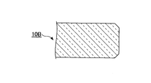
- FIG. 4 is a view showing an end portion of the polished glass plate obtained in Example 1.
- FIG. 4 In the glass plate 10B after polishing shown in FIG. 4, the shape of the chamfered portion was kept flat. It is estimated that the brush bristles having an average diameter of 200 mm have a small stress applied to the chamfered portion of the glass plate.
- Comparative Example 1 In Comparative Example 1, the glass plate was polished in the same manner as in Example 1 except that the average diameter of the bristles was 400 ⁇ m and the pedestal was not rocked, and a glass plate B was obtained.
- the arithmetic average height (Sa) of the glass plate was 70 nm. Further, the arithmetic mean waviness of the glass plate (Wa), the minimum value (Wa min) is 4 nm, the maximum value (Wa max) is 100 nm, the ratio (Wa max / Wa min) was 25.
- the time required for polishing 5 ⁇ m was 25 minutes. Defects having a maximum diameter of 7 ⁇ m or more and a depth or height of 1 ⁇ m or more were observed on the polished surface of the glass plate, 10 pieces per 10000 mm 2 .
- Comparative Example 2 In Comparative Example 2, the same glass as in Example 1 was prepared, and the curved surface 111 of the glass plate 110 was polished with the polishing pad 120 as shown in FIG. As the polishing head 121, a circular SUS304 base metal having a diameter of 60 mm was prepared, and a polyurethane polishing pad 120 was attached to the tip of the polishing head 121. As the polishing pad 120, a surface in contact with the glass plate 110 having grooves in a grid shape with a pitch of 10 mm was used.
- the polishing pad 120 was pressed against the glass plate 110 with a pressure of 150 g / cm 2 while rotating at 150 rpm.
- the glass plate 110 was vacuum-adsorbed to the pedestal 130 to maintain the upper surface of the glass plate 110 as a concave curved surface 111.
- a slurry containing cerium oxide particles was supplied to the polishing pad 120.
- the polishing pad 120 was moved on the glass plate 110 in the X direction and the Y direction at a speed of 60 mm / min, and the entire surface of the curved surface 111 was polished by 5 ⁇ m.
- the time required for polishing was 300 minutes. Thus, a glass plate C was obtained.
- the arithmetic average height (Sa) of the polished surface of the glass plate 110 was 1.6 nm. Further, the arithmetic mean waviness of the polished surface of the glass plate 110 (Wa) is a minimum value (Wa min) is 1.5 nm, the maximum value (Wa max) is 2 nm, the ratio (Wa max / Wa min) 1.3 Met. The defect that the maximum diameter was 7 ⁇ m or more and the depth or height was 1 ⁇ m or more was not observed on the polished surface of the glass plate 110.
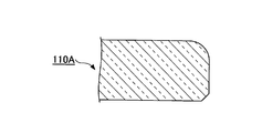
- FIG. 6 is a view showing the edge of the polished glass plate obtained in Comparative Example 2.
- the shape of the chamfered portion does not maintain a planar shape, and has a curved shape. It is presumed that the stress when the polishing pad is in contact with the chamfered portion of the glass plate 110A is large.
- the OCA tape (“MHM-FWD” manufactured by Niei Kakko Co., Ltd.) is laminated on the opposite side of the polished surface of the glass plates A to C, and each of these glass plates and a liquid crystal panel as a display panel are bonded to each other.
- a display device was manufactured in combination with the above. In the display device using the glass plate A, when the image on the liquid crystal panel was visually recognized through the glass plate A, the image was not distorted, swelled, or flickered.
- the central portion of the glass plate C had the same visibility as the glass plate A, but the chamfered portion was also polished, so that the peripheral portion of the glass plate C can also be visually recognized.
- the image looked distorted. This is because Wa max / Wa min and Sa are small, but the peripheral portion has a curved shape as shown in FIG. 6, and the visibility is different between the central portion and the peripheral portion of the glass plate C. This is because the image looks distorted. Therefore, it turned out that the glass plate A is suitable as a cover glass used for a display apparatus.
- the glass plate may not have a chamfered portion at the outer peripheral end before polishing, but preferably has a chamfered portion at the outer peripheral end.
- tip of an outer peripheral edge part can be suppressed at the time of grinding
- the shape of the chamfered portion may be a curved surface shape before polishing, but is preferably a planar shape.
- the dimensional variation of the chamfered portion is small before and after polishing.
- the chamfer angle of the planar chamfer is, for example, 40 to 50 °.
- polishing may be carried out by applying an external force such as by adsorbing the glass plate to the pedestal to increase the radius of curvature of the glass plate having a small radius of curvature.
- the rotating brush of this embodiment can grind
- polishing surface about the glass plate which has both a curved surface and a plane on a grinding
- the minimum radius of the rotating core be equal to or smaller than the minimum radius of curvature of the concave surface of the polishing surface.
- the surface of the glass plate obtained in this embodiment is preferably smooth.
- the arithmetic average roughness Ra is preferably 0.2 nm to 50 nm from the viewpoint of visibility, touch, and the like.
- the root mean square roughness Rq is preferably 0.3 to 100 nm from the viewpoint of slipperiness and slipperiness.
- the maximum height roughness Rz is preferably 0.5 to 100 nm from the viewpoint of slipperiness, which is rough.
- the maximum cross-sectional height roughness Rt is preferably 1 to 500 nm from the viewpoint of slipperiness, which indicates roughness.
- the maximum peak height roughness Rp is preferably 0.3 to 500 nm from the viewpoint of slipperiness.
- the maximum valley depth roughness Rv is preferably from 0.3 to 500 nm from the viewpoint of slipperiness.
- the average length roughness Rsm is preferably 0.3 to 100 nm from the viewpoint of slipperiness, which is rough.
- the kurtosis roughness Rku is preferably 1 or more and 3 or less from the viewpoint of touch.
- the skewness roughness Rsk is preferably ⁇ 1 or more and 1 or less from the viewpoint of uniformity such as visibility and touch.
- the glass plate obtained in the present embodiment may be subjected to various treatments before and after polishing.
- the chamfering process using a grinding wheel or an acid may be performed before the polishing process, may be performed after the polishing process, or may be performed both before and after the polishing process.
- surface treatment may be performed before and after polishing to form a surface treatment layer. Specifically, an antiglare treatment layer by etching or film formation, an antireflection treatment layer, an antifouling treatment layer by an anti-fingerprinting agent, etc. And an anti-fogging treatment layer. When the polishing treatment is performed after the surface treatment, only the untreated surface is polished.
- the glass plate may be strengthened before and after the polishing treatment, and a chemical strengthening treatment is preferred.
- chemical strengthening after the polishing treatment uniform strengthening can be put in the glass plate surface.
- chemical strengthening before the polishing treatment it is possible to remove the strengthened scratches on the glass plate surface. Therefore, the polishing treatment may be performed both before and after the chemical strengthening treatment depending on the situation.
- a printing process such as decorative printing may be performed before and after the polishing process. Not limited to these, various processes can be performed, and the order of the processes may be determined as appropriate.
- the composition of the glass plate is, for example, non-alkali glass or soda lime glass when chemical strengthening treatment is not performed, for example, soda lime glass, soda lime silicate glass, aluminosilicate glass when chemical strengthening treatment is performed, Examples thereof include borate glass, lithium aluminosilicate glass, and borosilicate glass.
- Aluminosilicate glass is preferred because it is easy to be subjected to a tempering treatment even if the thickness is small, and a high-strength glass can be obtained even if it is thin.
- the glass composition include a composition expressed in mol%, SiO 2 50 to 80%, Al 2 O 3 0.1 to 25%, Li 2 O + Na 2 O + K 2 O 3 to 30%, MgO Glass containing 0 to 25% of Ca, 0 to 25% of CaO and 0 to 5% of ZrO 2 , but is not particularly limited. More specifically, the following glass compositions may be mentioned. For example, “containing 0 to 25% of MgO” means that MgO is not essential but may contain up to 25%.
- the glass of (i) is contained in soda lime silicate glass, and the glass of (ii) and (iii) is contained in aluminosilicate glass.
- composition expressed in mol% is SiO 2 50-74%, Al 2 O 3 1-10%, Na 2 O 6-14%, K 2 O 3-11%, Li 2 O 0 to 5.0%, MgO 2 to 15%, CaO 0 to 6% and ZrO 2 0 to 5%, and the total content of SiO 2 and Al 2 O 3 is 75% or less, Na A glass having a total content of 2 O and K 2 O of 12 to 25% and a total content of MgO and CaO of 7 to 15%.
- composition expressed in mol% is SiO 2 68-80%, Al 2 O 3 4-10%, Na 2 O 5-15%, K 2 O 0-1%, Li 2 O Containing 0 to 5.0% of Mg, 4 to 15% of MgO, and 0 to 1% of ZrO 2 .
- the composition expressed in mol% is SiO 2 67-75%, Al 2 O 3 0-4%, Na 2 O 7-15%, K 2 O 1-9%, Li 2 O 0 to 5.0%, MgO 6 to 14% and ZrO 2 0 to 1.5%, and the total content of SiO 2 and Al 2 O 3 is 71 to 75%, Na 2 O and K Glass whose total content of 2 O is 12 to 20%, and when CaO is contained, the content is less than 1%.
- the total content of Li 2 O and Na 2 O in the glass composition is 12 mol% or more. Furthermore, as the Li 2 O content in the glass composition increases, the glass transition point decreases and molding becomes easy. Therefore, the Li 2 O content is preferably 0.5 mol% or more. More preferably, it is 0.0 mol% or more, and more preferably 2.0 mol% or more. Furthermore, in order to increase the surface compressive stress (Compressive Stress: CS) and the compressive stress layer depth (Depth of Layer: DOL), the glass composition contains 60 mol% or more of SiO 2 and 8 mol% or more of Al 2 O 3. It is preferable to do.
- Compressive Stress: CS Compressive Stress
- DOL compressive stress layer depth
- the maximum value of CS is 400 MPa or more, preferably 500 MPa or more, and more preferably 600 MPa or more.
- DOL is 10 ⁇ m or more.
- alkali metal ions typically Na ions
- alkali metal ions typically This is a process of forming a compressive stress layer on the glass surface by exchanging with K ions.
- the chemical strengthening treatment can be performed by a conventionally known method, and generally the glass is immersed in molten potassium nitrate. Further, a mixed salt of potassium nitrate and potassium carbonate can be used as the molten salt, and it is preferable that 5 to 10 parts by mass of potassium carbonate is contained with respect to 100 parts by mass of the mixed salt.
- the glass is ion-exchanged to have silver ions on the surface and impart antibacterial properties.
- the glass plate having a curved shape is preferably formed into a predetermined shape from a flat glass plate.
- the molding method to be used is a self-weight molding method, a vacuum molding method, a press molding method, or a desired molding method according to the desired curved shape of the glass after molding. Just choose.
- the self-weight molding method a plate glass is placed on a predetermined mold corresponding to a curved surface shape after molding, and then the plate glass is softened and bent into a predetermined shape by bending the plate glass by gravity. Is the method.
- the vacuum forming method is a method of forming a predetermined shape by applying a differential pressure to the front and back surfaces of the plate glass while the plate glass is softened, bending the plate glass and fitting it into a mold.
- a plate glass is set on a predetermined mold corresponding to the shape of the curved surface after forming, a clamp mold is set on the plate glass, the periphery of the plate glass is sealed, and then the space between the mold and the plate glass is set.
- a differential pressure is applied to the front and back surfaces of the plate glass. Under the present circumstances, you may pressurize the upper surface side of plate glass auxiliary.
- a plate glass is set between predetermined molds (lower mold, upper mold) according to the curved surface shape after molding, and a press load is applied between the upper and lower molds in a state where the plate glass is softened.
- This is a method of forming a predetermined shape by bending a plate glass and fitting it into a mold.
- the vacuum forming method is excellent as a method for forming a curved surface shape, and one of the two main surfaces of the glass plate can be formed without contacting the mold, so that scratches, dents, etc. Reduces uneven defects.
- a local pressure forming method, a differential pressure forming method different from the vacuum forming method, and the like can be used, and an appropriate forming method may be selected depending on the glass plate having a curved surface shape after forming.
- These molding methods may be used in combination. You may implement the process which reheats (annealing) about the glass plate after shaping
- the use of the glass plate of the present embodiment is not particularly limited. Specific examples include transparent parts for vehicles (headlight covers, side mirrors, front transparent boards, side transparent boards, rear transparent boards, instrument panel surfaces, etc.), meters, building windows, show windows, interior parts for buildings. , Exterior materials for buildings, displays (notebook computers, monitors, LCDs, PDPs, ELDs, CRTs, PDAs, etc.), LCD color filters, touch panel substrates, pickup lenses, optical lenses, eyeglass lenses, camera parts, video parts, CCDs Cover substrates, optical fiber end faces, projector parts, copier parts, transparent substrates for solar cells (cover glass, etc.), mobile phone windows, backlight unit parts (light guide plates, cold cathode tubes, etc.), backlight unit parts Liquid crystal brightness enhancement film (prism, transflective film, etc.), liquid crystal brightness direction Film, organic EL light-emitting element component, inorganic EL light-emitting element component, phosphor light-emitting element component, optical filter, end face of optical component
- the article of the present invention includes the glass plate of the present embodiment.
- the article of the present invention may be composed of the glass plate of the present embodiment, or may further include other members other than the glass plate of the present embodiment.
- Examples of the article of the present invention include those mentioned above for the use of the glass plate, devices provided with any one or more of them, and the like.
- Examples of the device include an image display device, a lighting device, and a solar cell module.
- the article of the present invention is preferably an image display device in terms of uniform optical properties such as visibility.
Landscapes
- Engineering & Computer Science (AREA)
- Chemical & Material Sciences (AREA)
- Mechanical Engineering (AREA)
- Geochemistry & Mineralogy (AREA)
- Chemical Kinetics & Catalysis (AREA)
- General Chemical & Material Sciences (AREA)
- Life Sciences & Earth Sciences (AREA)
- Materials Engineering (AREA)
- Organic Chemistry (AREA)
- Ceramic Engineering (AREA)
- Inorganic Chemistry (AREA)
- Surface Treatment Of Glass (AREA)
- Grinding And Polishing Of Tertiary Curved Surfaces And Surfaces With Complex Shapes (AREA)
- Devices For Indicating Variable Information By Combining Individual Elements (AREA)
Abstract
Description
ガラス板の曲面を研磨具により研磨する研磨工程を有する、ガラス板の製造方法であって、
前記研磨具は、回転ブラシであって、回転芯と前記回転芯の外周部に設けられるブラシ毛とを有し、
前記ブラシ毛の平均直径が300μm以下であり、
前記研磨工程では、前記ガラス板に対する前記回転ブラシの相対位置を前記回転ブラシの軸方向に揺動させ、
揺動速度の大きさが1mm/sec以上、揺動振幅が0.5mm以上である、ガラス板の製造方法が提供される。
回転芯21の最小半径が研磨面の最小曲率半径より小さいと均一な研磨を実施でき、良好な研磨面を有するガラス板が得られる。
ブラシ毛22の長さは2mm以上であることが好ましく、5mm以上であることが好ましい。ブラシ毛22の長さが2mm以上であれば、研磨面にブラシ毛22を押し当てた際にブラシ毛22の反発力による接触圧が強くなりすぎず、傷の少ない研磨面が得られる。またブラシ毛22の長さは100mm以下が好ましく、50mm以下がより好ましい。ブラシ毛22の長さが100mm以下であれば、研磨面にブラシ毛22を押し当てた際にブラシ毛22の反発力による接触圧が適度に得られ高い研磨速度が得られる。
また、ガラス板10を台座30に載置させる場合、載置面にガラス板10を嵌め込む凹部を設けてもよい。ガラス板10が回転ブラシ20に引きずられて台座30に対しずれることを抑制でき、ガラス板10の擦り傷を低減できる。さらにガラス板10の面取り部に圧力が集中して図6に示すように面取り部が丸まってしまうことを抑制できる。
さらに凹部の側壁面に窪みを設けてもよい。窪みにへらなどを差し込むことで研磨後のガラス板10を凹部から取り除きやすく、ガラス板10の交換の効率が良い。
ガラス板としては、最小曲率半径1500mm、縦150mm、横150mm、厚さ1mmのソーダライムガラスを用意した。このガラス板は、円筒体の一部で構成され、X方向に垂直な断面視で湾曲しており、Y方向に垂直な断面視で平らであった。このガラス板は、上面と端面の境界および下面と端面の境界のそれぞれに、面取り角度が45°、面取り幅が0.1mmの平面形状の面取り部を有するものであった。ここで、面取り角度とは、上面または下面の延長面と面取り部とのなす角度を意味する。また、面取り幅とは、上面または下面の外縁から、上面または下面の延長面と端面の延長面との交点までの距離とし、面取り部の寸法を意味する。
比較例1では、ブラシ毛の平均直径を400μmとし、且つ、台座の揺動を行わない以外、実施例1と同様にガラス板の研磨を行い、ガラス板Bを得た。
比較例2では実施例1と同じガラスを用意し、図5のように研磨パッド120でガラス板110の曲面111を研磨した。研磨ヘッド121は径がφ60mmの円形のSUS304製の台金を用意し、研磨ヘッド121の先端にポリウレタン製の研磨パッド120を取り付けた。研磨パッド120はガラス板110と接する面に10mmピッチで格子状に溝を切ってあるものを使用した。
以上、ガラス板の製造方法の実施形態などを説明したが、本発明は上記実施形態などに限定されず、特許請求の範囲に記載された本発明の要旨の範囲内において、種々の変形、改良が可能である。
また、ガラス板を台座に吸着させる等で外力をかけ、小さな曲率半径のガラス板の曲率半径を大きくさせ、研磨を実施してもよい。
本実施形態によれば大型の曲面形状を有するガラス板を研磨できる点で優れている。従来の研磨法によれば、部分ごとに研磨する必要があるため均一性にバラつきがでる。本実施形態によれば回転ブラシなどのサイズを調整するだけで様々なサイズの曲面形状を有するガラス板を均一に研磨できる。
(i)モル%で表示した組成で、SiO2を63~73%、Al2O3を0.1~5.2%、Na2Oを10~16%、K2Oを0~1.5%、Li2Oを0~5.0%、MgOを5~13%及びCaOを4~10%を含むガラス。
(ii)モル%で表示した組成が、SiO2を50~74%、Al2O3を1~10%、Na2Oを6~14%、K2Oを3~11%、Li2Oを0~5.0%、MgOを2~15%、CaOを0~6%およびZrO2を0~5%含有し、SiO2およびAl2O3の含有量の合計が75%以下、Na2OおよびK2Oの含有量の合計が12~25%、MgOおよびCaOの含有量の合計が7~15%であるガラス。
(iii)モル%で表示した組成が、SiO2を68~80%、Al2O3を4~10%、Na2Oを5~15%、K2Oを0~1%、Li2Oを0~5.0%、MgOを4~15%およびZrO2を0~1%含有するガラス。
(iv)モル%で表示した組成が、SiO2を67~75%、Al2O3を0~4%、Na2Oを7~15%、K2Oを1~9%、Li2Oを0~5.0%、MgOを6~14%およびZrO2を0~1.5%含有し、SiO2およびAl2O3の含有量の合計が71~75%、Na2OおよびK2Oの含有量の合計が12~20%であり、CaOを含有する場合その含有量が1%未満であるガラス。
化学強化処理したガラスは、CSの最大値が400MPa以上であり、500MPa以上が好ましく、600MPa以上がより好ましい。DOLは10μm以上である。これによりCSおよびDOLを当該範囲とすることにより、ガラス主面に優れた強度と耐擦傷性を付与できる。
自重成形法は、成形後の曲面形状に応じた所定の金型上に板ガラスを設置した後、板ガラスを軟化させて、重力により板ガラスを曲げて金型になじませて、所定の形状に成形する方法である。
これらのうち真空成形法は、曲面形状に成形する方法として優れており、ガラス板の二つの主面のうち、一方の主面は成形型と接触せずに成形できるため、傷、へこみなどの凹凸状欠点を減らせる。
なお、他に、局所加熱成形法、真空成形法と異なる差圧成形法なども使用でき、成形後の曲面形状を有するガラス板に応じて、適切な成形法を選択すればよく、2種以上の成形法を併用してもよい。
成形後のガラス板について再加熱(アニール処理)して残留応力を緩和させる処理を実施してもよい。
また、使用する平板状のガラス板には、エッチング処理層やウェットコートやドライコートによるコーティング層などを有する基材を用いてもよい。
本発明の物品は、本実施形態のガラス板からなるものでもよく、本実施形態のガラス板以外の他の部材をさらに備えるものでもよい。
本発明の物品の例としては、前記でガラス板の用途として挙げたもの、それらのいずれか1種以上を備える装置、等が挙げられる。
装置としては、例えば画像表示装置、照明装置、太陽電池モジュール等が挙げられる。
本発明の物品は、均一な視認性等の光学特性の点で、画像表示装置であることが好ましい。特に、大型の曲面形状を有するガラス板が求められる、液晶パネルや有機ELパネルなどの表示パネルが貼合された表示装置に適しており、さらに複雑な曲面形状を備える車載用表示装置に適している。これにより複雑な曲面形状を備えているガラス板であっても均一に研磨でき、均一な視認性が確保できる。
11 曲面
12 反対面
20 回転ブラシ
21 回転芯
22 ブラシ毛
30 台座
31 曲面
40 旋回テーブル
41 旋回軸
Claims (11)
- ガラス板の曲面を研磨具により研磨する研磨工程を有する、ガラス板の製造方法であって、
前記研磨具は、回転ブラシであって、回転芯と前記回転芯の外周部に設けられるブラシ毛とを有し、
前記ブラシ毛の平均直径が300μm以下であり、
前記研磨工程では、前記ガラス板に対する前記回転ブラシの相対位置を前記回転ブラシの軸方向に揺動させ、
揺動速度の大きさが1mm/sec以上、揺動振幅が0.5mm以上である、ガラス板の製造方法。 - ガラス板の曲面を研磨具により研磨する研磨工程を有する、ガラス板の製造方法であって、
前記研磨具は、回転ブラシであって、回転芯と前記回転芯の外周部に設けられるブラシ毛とを有し、
前記ブラシ毛の平均直径が300μm以下であり、
前記研磨工程では、前記ガラス板に対する前記回転ブラシの相対位置を前記回転ブラシの軸方向に揺動させ、
揺動速度の大きさが1mm/sec以上、揺動振幅が3mm以上である、ガラス板の製造方法。 - 前記研磨工程では、前記ガラス板の前記曲面の反対面を台座の曲面で真空吸着させる、請求項1または2に記載のガラス板の製造方法。
- 前記研磨工程では、前記ガラス板を真空吸着する台座を旋回させる、請求項1~3のいずれか一項に記載のガラス板の製造方法。
- 前記台座の前記ガラス板と接触する部位が、ポリ塩化ビニル、ポリカーボネート、ポリアセタール、アクリル、ポリアミド、ポリウレタン、ポリプロピレンからなる群より選ばれる少なくとも1つの樹脂材料からなる、請求項3または4に記載のガラス板の製造方法。
- 板厚が0.5~3.0mmであるガラス板であって、
曲面を有し、
前記曲面の少なくとも一部において、波長25~500μmの周波数成分の算術平均高さ(Sa)が0.5~50nmであり、かつ、波長25~500μmの周波数成分の算術平均うねり(Wa)の最大値(Wamax)と最小値(Wamin)との比(Wamax/Wamin)が1.5以上であるガラス板。 - 板厚が0.5~3.0mmであるガラス板であって、
研磨済みの曲面を有し、
前記曲面の少なくとも一部において、波長25~500μmの周波数成分の算術平均高さ(Sa)が0.5~50nmであり、かつ、波長25~500μmの周波数成分の算術平均うねり(Wa)の最大値(Wamax)と最小値(Wamin)との比(Wamax/Wamin)が1.5以上であるガラス板。 - 板厚が0.5~5.0mmであるガラス板であって、
曲面を有し、
前記ガラス板の表面圧縮応力(Compressive Stress: CS)が400MPa以上であり、
前記曲面の少なくとも一部において、波長25~500μmの周波数成分の算術平均高さ(Sa)が0.5~50nmであり、かつ、波長25~500μmの周波数成分の算術平均うねり(Wa)の最大値(Wamax)と最小値(Wamin)との比(Wamax/Wamin)が1.5以上であるガラス板。 - 板厚が0.5~5.0mmである第1面と第2面とを有するガラス板であって、
曲面を有し、
前記第1面に表面処理層を備え、
前記ガラス板の表面圧縮応力(Compressive Stress: CS)が400MPa以上であり、
前記第2面における前記曲面の少なくとも一部において、波長25~500μmの周波数成分の算術平均高さ(Sa)が0.5~50nmであり、かつ、波長25~500μmの周波数成分の算術平均うねり(Wa)の最大値(Wamax)と最小値(Wamin)との比(Wamax/Wamin)が1.5以上であるガラス板。 - 前記曲面の少なくとも一部において、最大径が7μm以上であり、且つ深さまたは高さが1μm以上である欠点が、10000mm2あたり3個以下である、請求項6~9のいずれか一項に記載のガラス板。
- 請求項6~10のいずれか一項に記載のガラス板と表示パネルとを備えた表示装置。
Priority Applications (4)
| Application Number | Priority Date | Filing Date | Title |
|---|---|---|---|
| JP2017523589A JP6881301B2 (ja) | 2015-06-12 | 2016-05-30 | ガラス板の製造方法 |
| CN201690000902.8U CN208378728U (zh) | 2015-06-12 | 2016-05-30 | 玻璃板和显示装置 |
| DE112016002662.5T DE112016002662T5 (de) | 2015-06-12 | 2016-05-30 | Verfahren zur herstellung einer glasplatte, glasplatte und anzeigevorrichtung |
| US15/813,339 US20180071881A1 (en) | 2015-06-12 | 2017-11-15 | Method for manufacturing glass plate, glass plate, and display device |
Applications Claiming Priority (2)
| Application Number | Priority Date | Filing Date | Title |
|---|---|---|---|
| JP2015118863 | 2015-06-12 | ||
| JP2015-118863 | 2015-06-12 |
Related Child Applications (1)
| Application Number | Title | Priority Date | Filing Date |
|---|---|---|---|
| US15/813,339 Continuation US20180071881A1 (en) | 2015-06-12 | 2017-11-15 | Method for manufacturing glass plate, glass plate, and display device |
Publications (1)
| Publication Number | Publication Date |
|---|---|
| WO2016199612A1 true WO2016199612A1 (ja) | 2016-12-15 |
Family
ID=57503744
Family Applications (1)
| Application Number | Title | Priority Date | Filing Date |
|---|---|---|---|
| PCT/JP2016/065920 Ceased WO2016199612A1 (ja) | 2015-06-12 | 2016-05-30 | ガラス板の製造方法、ガラス板、および表示装置 |
Country Status (5)
| Country | Link |
|---|---|
| US (1) | US20180071881A1 (ja) |
| JP (1) | JP6881301B2 (ja) |
| CN (2) | CN210163336U (ja) |
| DE (1) | DE112016002662T5 (ja) |
| WO (1) | WO2016199612A1 (ja) |
Cited By (12)
| Publication number | Priority date | Publication date | Assignee | Title |
|---|---|---|---|---|
| JP2018126847A (ja) * | 2017-02-10 | 2018-08-16 | 旭硝子株式会社 | 基材処理装置 |
| KR20190021164A (ko) * | 2017-08-22 | 2019-03-05 | 가부시기가이샤 디스코 | 연삭 방법 |
| JP2019085276A (ja) * | 2017-11-01 | 2019-06-06 | Agc株式会社 | 3dカバーガラス、およびその製造方法 |
| WO2019131431A1 (ja) * | 2017-12-27 | 2019-07-04 | Hoya株式会社 | 円盤状ガラス基板の製造方法、薄板ガラス基板の製造方法、導光板の製造方法及び円盤状ガラス基板 |
| JP2020124804A (ja) * | 2020-04-21 | 2020-08-20 | Hoya株式会社 | 円盤状ガラス基板の製造方法、薄板ガラス基板の製造方法、導光板の製造方法及び円盤状ガラス基板 |
| JP2020533190A (ja) * | 2017-09-12 | 2020-11-19 | カール・ツァイス・エスエムティー・ゲーエムベーハー | 光学素子の製造時に加工物を加工する方法 |
| JP2021094808A (ja) * | 2019-12-18 | 2021-06-24 | 日本板硝子株式会社 | カバーガラス |
| JP2021133490A (ja) * | 2020-02-28 | 2021-09-13 | 国立大学法人 東京大学 | 修正研磨加工方法および修正研磨加工装置 |
| JP2022511740A (ja) * | 2018-11-27 | 2022-02-01 | コーニング インコーポレイテッド | 改善された表面及び縁部品質を有するヘッドアップディスプレイミラー、及びその成形方法 |
| TWI778194B (zh) * | 2017-12-18 | 2022-09-21 | 日商Agc股份有限公司 | 顯示器用玻璃基板 |
| JP2022548702A (ja) * | 2019-09-18 | 2022-11-21 | ショット アクチエンゲゼルシャフト | 立体的に変形された薄ガラス |
| US12091348B2 (en) | 2017-07-12 | 2024-09-17 | Corning Incorporated | Apparatus and methods for manufacturing a glass substrate |
Families Citing this family (10)
| Publication number | Priority date | Publication date | Assignee | Title |
|---|---|---|---|---|
| KR101994051B1 (ko) * | 2016-05-23 | 2019-06-27 | 닛폰세이테츠 가부시키가이샤 | 형상 측정 장치 및 형상 측정 방법 |
| DE102016125544B4 (de) * | 2016-12-23 | 2020-10-01 | Glaswerke Arnold Gmbh & Co. Kg | Verfahren zur Herstellung einer biozid wirkenden Glasoberfläche eines Kalk-Natronsilicatglases |
| AU2019100242A4 (en) * | 2018-03-07 | 2019-04-18 | Schott Ag | Articles that can be burner shields having grease flow control and/or chemical resistance |
| WO2020069260A1 (en) * | 2018-09-28 | 2020-04-02 | Corning Incorporated | Glass-based articles with improved stress profiles |
| WO2021012144A1 (zh) * | 2019-07-22 | 2021-01-28 | 重庆鑫景特种玻璃有限公司 | 减反射玻璃及其制备方法与应用 |
| WO2022039056A1 (ja) * | 2020-08-19 | 2022-02-24 | Agc株式会社 | 化学強化ガラス |
| US20260010247A1 (en) * | 2022-07-08 | 2026-01-08 | Nippon Electric Glass Co., Ltd. | Top panel for tactile sense presentation device, tactile sense presentation device, and method for manufacturing top panel for tactile sense presentation device |
| CN115521077B (zh) * | 2022-10-28 | 2023-09-22 | 佛山市晶玻科技有限公司 | 曲面淋漆工艺 |
| CN116175377A (zh) * | 2022-12-14 | 2023-05-30 | 中国建筑材料科学研究总院有限公司 | 复杂表面的抛光方法及防光晕光电玻璃窗的抛光设备 |
| DE102023213187A1 (de) * | 2023-12-21 | 2025-06-26 | Carl Zeiss Smt Gmbh | Verfahren zum Glätten einer Oberfläche eines Substrats |
Citations (6)
| Publication number | Priority date | Publication date | Assignee | Title |
|---|---|---|---|---|
| JPH06312360A (ja) * | 1993-04-26 | 1994-11-08 | Central Glass Co Ltd | ガラス板面の給電・端子部研磨装置 |
| JP2002210647A (ja) * | 2001-01-15 | 2002-07-30 | Seiko Epson Corp | 光学レンズの平滑処理方法およびこれを用いた光学レンズの製造方法、光学レンズの平滑処理装置 |
| JP2009502721A (ja) * | 2005-08-02 | 2009-01-29 | ショット アクチエンゲゼルシャフト | 板ガラスを後処理する方法及び装置 |
| JP2011134432A (ja) * | 2009-11-26 | 2011-07-07 | Asahi Glass Co Ltd | 磁気記録媒体用ガラス基板およびその製造方法 |
| JP2012142044A (ja) * | 2010-12-28 | 2012-07-26 | Konica Minolta Advanced Layers Inc | 情報記録媒体用ガラス基板の製造方法および情報記録媒体 |
| JP2013220486A (ja) * | 2012-04-13 | 2013-10-28 | Konica Minolta Inc | ディスプレイ用カバーガラスの研磨方法および研磨装置 |
Family Cites Families (5)
| Publication number | Priority date | Publication date | Assignee | Title |
|---|---|---|---|---|
| SG88773A1 (en) * | 1999-03-31 | 2002-05-21 | Hoya Corp | Substrate for an information recording medium, information recording medium using the substrate, and method of producing the substrate |
| US9434644B2 (en) * | 2010-09-30 | 2016-09-06 | Avanstrate Inc. | Cover glass and method for producing cover glass |
| CN104736651A (zh) * | 2011-11-09 | 2015-06-24 | 罗地亚经营管理公司 | 添加剂混合物和组合物以及用于抛光玻璃基底的方法 |
| KR102157750B1 (ko) * | 2012-11-29 | 2020-09-21 | 코닝 인코포레이티드 | 레이저 손상 및 에칭에 의한 유리 제품의 제조방법 |
| TW201704177A (zh) * | 2015-06-10 | 2017-02-01 | 康寧公司 | 蝕刻玻璃基板的方法及玻璃基板 |
-
2016
- 2016-05-30 CN CN201822191444.4U patent/CN210163336U/zh active Active
- 2016-05-30 JP JP2017523589A patent/JP6881301B2/ja active Active
- 2016-05-30 WO PCT/JP2016/065920 patent/WO2016199612A1/ja not_active Ceased
- 2016-05-30 DE DE112016002662.5T patent/DE112016002662T5/de not_active Withdrawn
- 2016-05-30 CN CN201690000902.8U patent/CN208378728U/zh active Active
-
2017
- 2017-11-15 US US15/813,339 patent/US20180071881A1/en not_active Abandoned
Patent Citations (6)
| Publication number | Priority date | Publication date | Assignee | Title |
|---|---|---|---|---|
| JPH06312360A (ja) * | 1993-04-26 | 1994-11-08 | Central Glass Co Ltd | ガラス板面の給電・端子部研磨装置 |
| JP2002210647A (ja) * | 2001-01-15 | 2002-07-30 | Seiko Epson Corp | 光学レンズの平滑処理方法およびこれを用いた光学レンズの製造方法、光学レンズの平滑処理装置 |
| JP2009502721A (ja) * | 2005-08-02 | 2009-01-29 | ショット アクチエンゲゼルシャフト | 板ガラスを後処理する方法及び装置 |
| JP2011134432A (ja) * | 2009-11-26 | 2011-07-07 | Asahi Glass Co Ltd | 磁気記録媒体用ガラス基板およびその製造方法 |
| JP2012142044A (ja) * | 2010-12-28 | 2012-07-26 | Konica Minolta Advanced Layers Inc | 情報記録媒体用ガラス基板の製造方法および情報記録媒体 |
| JP2013220486A (ja) * | 2012-04-13 | 2013-10-28 | Konica Minolta Inc | ディスプレイ用カバーガラスの研磨方法および研磨装置 |
Cited By (20)
| Publication number | Priority date | Publication date | Assignee | Title |
|---|---|---|---|---|
| JP2018126847A (ja) * | 2017-02-10 | 2018-08-16 | 旭硝子株式会社 | 基材処理装置 |
| US12091348B2 (en) | 2017-07-12 | 2024-09-17 | Corning Incorporated | Apparatus and methods for manufacturing a glass substrate |
| KR20190021164A (ko) * | 2017-08-22 | 2019-03-05 | 가부시기가이샤 디스코 | 연삭 방법 |
| KR102554989B1 (ko) | 2017-08-22 | 2023-07-12 | 가부시기가이샤 디스코 | 연삭 방법 |
| JP2020533190A (ja) * | 2017-09-12 | 2020-11-19 | カール・ツァイス・エスエムティー・ゲーエムベーハー | 光学素子の製造時に加工物を加工する方法 |
| US11980990B2 (en) | 2017-09-12 | 2024-05-14 | Carl Zeiss Smt Gmbh | Method for machining a workpiece in the production of an optical element |
| JP7343486B2 (ja) | 2017-09-12 | 2023-09-12 | カール・ツァイス・エスエムティー・ゲーエムベーハー | 光学素子の製造時に加工物を加工する方法 |
| JP2019085276A (ja) * | 2017-11-01 | 2019-06-06 | Agc株式会社 | 3dカバーガラス、およびその製造方法 |
| JP7031230B2 (ja) | 2017-11-01 | 2022-03-08 | Agc株式会社 | 3dカバーガラス、およびその製造方法 |
| TWI778194B (zh) * | 2017-12-18 | 2022-09-21 | 日商Agc股份有限公司 | 顯示器用玻璃基板 |
| WO2019131431A1 (ja) * | 2017-12-27 | 2019-07-04 | Hoya株式会社 | 円盤状ガラス基板の製造方法、薄板ガラス基板の製造方法、導光板の製造方法及び円盤状ガラス基板 |
| JP2019115952A (ja) * | 2017-12-27 | 2019-07-18 | Hoya株式会社 | 円盤状ガラス基板の製造方法、薄板ガラス基板の製造方法、導光板の製造方法及び円盤状ガラス基板 |
| JP2022511740A (ja) * | 2018-11-27 | 2022-02-01 | コーニング インコーポレイテッド | 改善された表面及び縁部品質を有するヘッドアップディスプレイミラー、及びその成形方法 |
| JP2022548702A (ja) * | 2019-09-18 | 2022-11-21 | ショット アクチエンゲゼルシャフト | 立体的に変形された薄ガラス |
| JP2021094808A (ja) * | 2019-12-18 | 2021-06-24 | 日本板硝子株式会社 | カバーガラス |
| JP7502022B2 (ja) | 2019-12-18 | 2024-06-18 | 日本板硝子株式会社 | カバーガラス |
| JP2021133490A (ja) * | 2020-02-28 | 2021-09-13 | 国立大学法人 東京大学 | 修正研磨加工方法および修正研磨加工装置 |
| JP7557166B2 (ja) | 2020-02-28 | 2024-09-27 | 国立大学法人 東京大学 | 修正研磨加工方法および修正研磨加工装置 |
| JP7003178B2 (ja) | 2020-04-21 | 2022-01-20 | Hoya株式会社 | 円盤状ガラス基板の製造方法、薄板ガラス基板の製造方法、導光板の製造方法及び円盤状ガラス基板 |
| JP2020124804A (ja) * | 2020-04-21 | 2020-08-20 | Hoya株式会社 | 円盤状ガラス基板の製造方法、薄板ガラス基板の製造方法、導光板の製造方法及び円盤状ガラス基板 |
Also Published As
| Publication number | Publication date |
|---|---|
| US20180071881A1 (en) | 2018-03-15 |
| JPWO2016199612A1 (ja) | 2018-03-29 |
| CN210163336U (zh) | 2020-03-20 |
| CN208378728U (zh) | 2019-01-15 |
| JP6881301B2 (ja) | 2021-06-02 |
| DE112016002662T5 (de) | 2018-03-08 |
Similar Documents
| Publication | Publication Date | Title |
|---|---|---|
| JP6881301B2 (ja) | ガラス板の製造方法 | |
| CN207291374U (zh) | 带有印刷层的板及显示装置 | |
| JP6833165B2 (ja) | 輸送機用内装組立体 | |
| JP6687044B2 (ja) | 曲面カバーガラス及びその製造方法、並びに車載用表示部材 | |
| JP7067077B2 (ja) | ガラス板及び表示装置 | |
| KR102011993B1 (ko) | 스파클 제어하기 위한 방법 및 이에 의한 제품 | |
| EP2646383B1 (en) | Anti-glare glass sheet having compressive stress equipoise and methods thereof | |
| CN102548922B (zh) | 具有防眩光性的玻璃和显示器 | |
| CN107814478B (zh) | 弯曲玻璃物品的制造方法和弯曲玻璃物品 | |
| JP6866908B2 (ja) | ガラス物品の製造方法 | |
| JP2017001940A (ja) | ガラス基板及びその製造方法、カバーガラス及びその製造方法、携帯情報端末、並びに表示装置 | |
| US20110267698A1 (en) | Anti-glare surface treatment method and articles thereof | |
| CN104661976A (zh) | 纹理化的玻璃表面及其制备方法 | |
| CN107867792A (zh) | 玻璃物品的制造方法和玻璃物品 | |
| JP2020024477A (ja) | カバー部材及びその製造方法、並びに携帯情報端末 | |
| JP6977642B2 (ja) | ガラス物品 | |
| CN114080371B (zh) | 玻璃基体以及其制造方法 | |
| CN111606573A (zh) | 带有凹凸形状的玻璃基体及其制造方法 | |
| WO2020255926A1 (ja) | ガラス基体 |
Legal Events
| Date | Code | Title | Description |
|---|---|---|---|
| 121 | Ep: the epo has been informed by wipo that ep was designated in this application |
Ref document number: 16807319 Country of ref document: EP Kind code of ref document: A1 |
|
| ENP | Entry into the national phase |
Ref document number: 2017523589 Country of ref document: JP Kind code of ref document: A |
|
| WWE | Wipo information: entry into national phase |
Ref document number: 112016002662 Country of ref document: DE |
|
| 122 | Ep: pct application non-entry in european phase |
Ref document number: 16807319 Country of ref document: EP Kind code of ref document: A1 |