WO2016194502A1 - 流量制御弁 - Google Patents
流量制御弁 Download PDFInfo
- Publication number
- WO2016194502A1 WO2016194502A1 PCT/JP2016/062458 JP2016062458W WO2016194502A1 WO 2016194502 A1 WO2016194502 A1 WO 2016194502A1 JP 2016062458 W JP2016062458 W JP 2016062458W WO 2016194502 A1 WO2016194502 A1 WO 2016194502A1
- Authority
- WO
- WIPO (PCT)
- Prior art keywords
- valve body
- control valve
- flow control
- section
- opening
- Prior art date
- Legal status (The legal status is an assumption and is not a legal conclusion. Google has not performed a legal analysis and makes no representation as to the accuracy of the status listed.)
- Ceased
Links
Images




Classifications
-
- F—MECHANICAL ENGINEERING; LIGHTING; HEATING; WEAPONS; BLASTING
- F01—MACHINES OR ENGINES IN GENERAL; ENGINE PLANTS IN GENERAL; STEAM ENGINES
- F01P—COOLING OF MACHINES OR ENGINES IN GENERAL; COOLING OF INTERNAL-COMBUSTION ENGINES
- F01P7/00—Controlling of coolant flow
- F01P7/14—Controlling of coolant flow the coolant being liquid
-
- F—MECHANICAL ENGINEERING; LIGHTING; HEATING; WEAPONS; BLASTING
- F01—MACHINES OR ENGINES IN GENERAL; ENGINE PLANTS IN GENERAL; STEAM ENGINES
- F01P—COOLING OF MACHINES OR ENGINES IN GENERAL; COOLING OF INTERNAL-COMBUSTION ENGINES
- F01P11/00—Component parts, details, or accessories not provided for in, or of interest apart from, groups F01P1/00 - F01P9/00
- F01P11/14—Indicating devices; Other safety devices
- F01P11/16—Indicating devices; Other safety devices concerning coolant temperature
-
- F—MECHANICAL ENGINEERING; LIGHTING; HEATING; WEAPONS; BLASTING
- F01—MACHINES OR ENGINES IN GENERAL; ENGINE PLANTS IN GENERAL; STEAM ENGINES
- F01P—COOLING OF MACHINES OR ENGINES IN GENERAL; COOLING OF INTERNAL-COMBUSTION ENGINES
- F01P7/00—Controlling of coolant flow
- F01P7/14—Controlling of coolant flow the coolant being liquid
- F01P7/16—Controlling of coolant flow the coolant being liquid by thermostatic control
- F01P7/165—Controlling of coolant flow the coolant being liquid by thermostatic control characterised by systems with two or more loops
-
- F—MECHANICAL ENGINEERING; LIGHTING; HEATING; WEAPONS; BLASTING
- F16—ENGINEERING ELEMENTS AND UNITS; GENERAL MEASURES FOR PRODUCING AND MAINTAINING EFFECTIVE FUNCTIONING OF MACHINES OR INSTALLATIONS; THERMAL INSULATION IN GENERAL
- F16K—VALVES; TAPS; COCKS; ACTUATING-FLOATS; DEVICES FOR VENTING OR AERATING
- F16K11/00—Multiple-way valves, e.g. mixing valves; Pipe fittings incorporating such valves
- F16K11/02—Multiple-way valves, e.g. mixing valves; Pipe fittings incorporating such valves with all movable sealing faces moving as one unit
- F16K11/08—Multiple-way valves, e.g. mixing valves; Pipe fittings incorporating such valves with all movable sealing faces moving as one unit comprising only taps or cocks
- F16K11/087—Multiple-way valves, e.g. mixing valves; Pipe fittings incorporating such valves with all movable sealing faces moving as one unit comprising only taps or cocks with spherical plug
- F16K11/0873—Multiple-way valves, e.g. mixing valves; Pipe fittings incorporating such valves with all movable sealing faces moving as one unit comprising only taps or cocks with spherical plug the plug being only rotatable around one spindle
- F16K11/0876—Multiple-way valves, e.g. mixing valves; Pipe fittings incorporating such valves with all movable sealing faces moving as one unit comprising only taps or cocks with spherical plug the plug being only rotatable around one spindle one connecting conduit having the same axis as the spindle
-
- F—MECHANICAL ENGINEERING; LIGHTING; HEATING; WEAPONS; BLASTING
- F16—ENGINEERING ELEMENTS AND UNITS; GENERAL MEASURES FOR PRODUCING AND MAINTAINING EFFECTIVE FUNCTIONING OF MACHINES OR INSTALLATIONS; THERMAL INSULATION IN GENERAL
- F16K—VALVES; TAPS; COCKS; ACTUATING-FLOATS; DEVICES FOR VENTING OR AERATING
- F16K11/00—Multiple-way valves, e.g. mixing valves; Pipe fittings incorporating such valves
- F16K11/10—Multiple-way valves, e.g. mixing valves; Pipe fittings incorporating such valves with two or more closure members not moving as a unit
- F16K11/105—Three-way check or safety valves with two or more closure members
-
- F—MECHANICAL ENGINEERING; LIGHTING; HEATING; WEAPONS; BLASTING
- F16—ENGINEERING ELEMENTS AND UNITS; GENERAL MEASURES FOR PRODUCING AND MAINTAINING EFFECTIVE FUNCTIONING OF MACHINES OR INSTALLATIONS; THERMAL INSULATION IN GENERAL
- F16K—VALVES; TAPS; COCKS; ACTUATING-FLOATS; DEVICES FOR VENTING OR AERATING
- F16K27/00—Construction of housing; Use of materials therefor
- F16K27/06—Construction of housing; Use of materials therefor of taps or cocks
- F16K27/067—Construction of housing; Use of materials therefor of taps or cocks with spherical plugs
-
- F—MECHANICAL ENGINEERING; LIGHTING; HEATING; WEAPONS; BLASTING
- F16—ENGINEERING ELEMENTS AND UNITS; GENERAL MEASURES FOR PRODUCING AND MAINTAINING EFFECTIVE FUNCTIONING OF MACHINES OR INSTALLATIONS; THERMAL INSULATION IN GENERAL
- F16K—VALVES; TAPS; COCKS; ACTUATING-FLOATS; DEVICES FOR VENTING OR AERATING
- F16K31/00—Actuating devices; Operating means; Releasing devices
- F16K31/02—Actuating devices; Operating means; Releasing devices electric; magnetic
- F16K31/025—Actuating devices; Operating means; Releasing devices electric; magnetic actuated by thermo-electric means
-
- F—MECHANICAL ENGINEERING; LIGHTING; HEATING; WEAPONS; BLASTING
- F16—ENGINEERING ELEMENTS AND UNITS; GENERAL MEASURES FOR PRODUCING AND MAINTAINING EFFECTIVE FUNCTIONING OF MACHINES OR INSTALLATIONS; THERMAL INSULATION IN GENERAL
- F16K—VALVES; TAPS; COCKS; ACTUATING-FLOATS; DEVICES FOR VENTING OR AERATING
- F16K31/00—Actuating devices; Operating means; Releasing devices
- F16K31/02—Actuating devices; Operating means; Releasing devices electric; magnetic
- F16K31/04—Actuating devices; Operating means; Releasing devices electric; magnetic using a motor
- F16K31/041—Actuating devices; Operating means; Releasing devices electric; magnetic using a motor for rotating valves
- F16K31/042—Actuating devices; Operating means; Releasing devices electric; magnetic using a motor for rotating valves with electric means, e.g. for controlling the motor or a clutch between the valve and the motor
-
- F—MECHANICAL ENGINEERING; LIGHTING; HEATING; WEAPONS; BLASTING
- F16—ENGINEERING ELEMENTS AND UNITS; GENERAL MEASURES FOR PRODUCING AND MAINTAINING EFFECTIVE FUNCTIONING OF MACHINES OR INSTALLATIONS; THERMAL INSULATION IN GENERAL
- F16K—VALVES; TAPS; COCKS; ACTUATING-FLOATS; DEVICES FOR VENTING OR AERATING
- F16K31/00—Actuating devices; Operating means; Releasing devices
- F16K31/02—Actuating devices; Operating means; Releasing devices electric; magnetic
- F16K31/04—Actuating devices; Operating means; Releasing devices electric; magnetic using a motor
- F16K31/041—Actuating devices; Operating means; Releasing devices electric; magnetic using a motor for rotating valves
- F16K31/043—Actuating devices; Operating means; Releasing devices electric; magnetic using a motor for rotating valves characterised by mechanical means between the motor and the valve, e.g. lost motion means reducing backlash, clutches, brakes or return means
-
- F—MECHANICAL ENGINEERING; LIGHTING; HEATING; WEAPONS; BLASTING
- F01—MACHINES OR ENGINES IN GENERAL; ENGINE PLANTS IN GENERAL; STEAM ENGINES
- F01P—COOLING OF MACHINES OR ENGINES IN GENERAL; COOLING OF INTERNAL-COMBUSTION ENGINES
- F01P11/00—Component parts, details, or accessories not provided for in, or of interest apart from, groups F01P1/00 - F01P9/00
- F01P11/14—Indicating devices; Other safety devices
- F01P11/18—Indicating devices; Other safety devices concerning coolant pressure, coolant flow, or liquid-coolant level
-
- F—MECHANICAL ENGINEERING; LIGHTING; HEATING; WEAPONS; BLASTING
- F01—MACHINES OR ENGINES IN GENERAL; ENGINE PLANTS IN GENERAL; STEAM ENGINES
- F01P—COOLING OF MACHINES OR ENGINES IN GENERAL; COOLING OF INTERNAL-COMBUSTION ENGINES
- F01P7/00—Controlling of coolant flow
- F01P7/14—Controlling of coolant flow the coolant being liquid
- F01P2007/146—Controlling of coolant flow the coolant being liquid using valves
-
- F—MECHANICAL ENGINEERING; LIGHTING; HEATING; WEAPONS; BLASTING
- F01—MACHINES OR ENGINES IN GENERAL; ENGINE PLANTS IN GENERAL; STEAM ENGINES
- F01P—COOLING OF MACHINES OR ENGINES IN GENERAL; COOLING OF INTERNAL-COMBUSTION ENGINES
- F01P2031/00—Fail safe
Definitions
- the present invention relates to a flow rate control valve used for controlling the flow rate of cooling water for automobiles.
- Patent Document 1 As a conventional flow control valve applied to the flow control of cooling water for automobiles, for example, the one described in Patent Document 1 below is known.
- This flow control valve is used to control the distribution of cooling water to auxiliary equipment such as radiators and heaters, and has an almost cylindrical shape in which one end in the axial direction is formed as an inlet and a plurality of outlets are formed in the peripheral wall. And a substantially cylindrical valve body that is rotatably accommodated on the inner peripheral side of the housing, has one axial end opening toward the introduction port, and a plurality of openings are formed in the peripheral wall.
- the cooling water introduced from the introduction port according to the rotational position of the valve body that is, the polymerization state of each opening and each discharge port, and the inner circumferential side passage of the valve body and the polymerization It can be distributed to the auxiliary machines through the opening and the outlet in the state.
- the present invention has been devised in view of such technical problems, and an object thereof is to provide a flow control valve capable of reducing the flow resistance of a fluid.
- the present invention has an opening formed in the axial direction of a hollow valve body housing portion, and is formed so as to have an introduction port for introducing fluid and an opening cross section smaller than the opening cross section of the introduction port.
- a housing having a plurality of discharge ports communicating with the body housing portion in the radial direction and used for discharging the fluid in the valve body housing portion, and rotatably supported in the housing, and each of the discharge ports depending on the rotation position.
- a valve body having a plurality of openings in which the polymerization state with the outlet changes, and in the axial direction of the valve body housing portion, the opening cross section between the introduction port and at least one discharge port is reduced. It is characterized by that.
- a bypass passage is provided outside the valve body in the radial direction of the valve body, and the side cross section is formed by the bypass passage to reduce the opening cross section. It is desirable.
- the opening cross section As another aspect relating to the reduction of the opening cross section, it is desirable to gradually reduce the opening cross section of the housing or the valve body. Thus, the flow resistance of the fluid can be more effectively reduced by gradually reducing the opening cross section.
- the present invention it is possible to suppress a rapid reduction in the flow path cross-sectional area of the fluid by reducing the opening cross section between the introduction port in the axial direction of the valve body housing portion and at least one discharge port. It becomes possible, and the flow resistance of the fluid can be reduced.
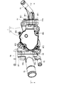
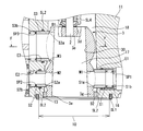
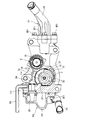
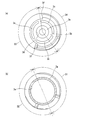
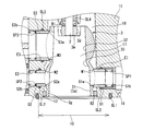
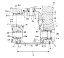
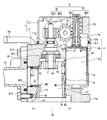
- FIG. 4 is a sectional view taken along line AA in FIG. 3.
- FIG. 6 is a sectional view taken along line BB of FIG.
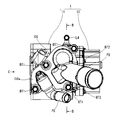
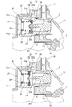
- FIG. 2 is a longitudinal cross-sectional view of the fail-safe valve shown in FIG. 2, (a) is a valve closing state, (b) is a figure which shows a valve opening state. It is the arrow view seen from the C direction of FIG.
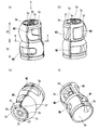
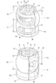
- FIG. 3 is a perspective view of the valve body shown in FIG. 2, and (a) to (d) are views showing states seen from different viewpoints.
- (A) is an arrow view seen from the D direction of FIG. 10 (a)
- (b) is the EE sectional view taken on the line of FIG. 10 (a).
- (a) is a state where all the discharge ports are out of communication
- (b) is a state where only the 1st discharge port is connected
- FIG. 4 is a development view of the valve body housing portion showing a state in which the first and second discharge ports are in communication with each other
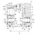
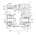
- FIG. It is principal part sectional drawing of the flow control valve showing the 1st other example of the form of the taper part shown in FIG. It is principal part sectional drawing of the flow control valve showing the 2nd other example of the form of the taper part shown in FIG. It is the figure showing the other example of the form of the valve body shown in FIG. 11, Comprising: (a) is the perspective view seen from radial direction one side, (b) is the perspective view seen from radial direction other side.
- FIG. 17 is a view corresponding to FIG. 4 showing a flow control valve to which the valve body shown in FIG. 16 is applied.
- FIG. 5 is a sectional view taken along line FF in FIG. 4.
- FIG. 5 is a view corresponding to FIG. 4 of a second embodiment of the flow control valve according to the present invention. It is principal part sectional drawing of the flow control valve showing the other example of the form of the taper part shown in FIG.
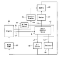
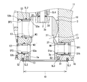
- FIG. 16 is a cross-sectional view of a main part of a flow control valve showing another example of the flow control valve shown in FIG. 15, which is another embodiment of the flow control valve according to the present invention.
- cooling water a circulating system for automotive cooling water
- FIG. 1 to 13 show a first embodiment of a flow control valve according to the present invention.
- the control valve CV is disposed at the side of the engine EG (specifically, a cylinder head (not shown)), and between the engine EG and the heating heat exchanger HT (EGR cooler EC), the oil cooler OC, and the radiator RD. Is arranged.
- the cooling water pressurized by the water pump WP and guided to the flow control valve CV through the introduction passage L0 is supplied to the heating heat exchanger HT, the oil cooler OC, and the radiator RD via the first to third pipes L1 to L3.
- Each flow is distributed to the side, and each flow rate is controlled.
- the cooling water led to the heating heat exchanger HT is led to the EGR cooler EC and then returned to the engine EG side.
- the flow rate control valve CV is provided with a bypass passage BL that bypasses the introduction passage L0 and directly leads the cooling water to the throttle chamber TC, and the cooling water guided from the engine EG side with the bypass passage BL. Can always be supplied to the throttle chamber TC. Then, the cooling water supplied to the throttle chamber TC is guided to the EGR cooler EC and is returned to the engine EG side through the EGR cooler EC, similarly to the heating heat exchanger HT.
- a symbol WT in FIG. 1 indicates a water temperature sensor.
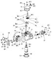
- the flow control valve CV includes a first housing 11 that houses a valve body 3 and an electric motor 4 described later. And a second housing 12 that houses a speed reduction mechanism 5 to be described later, and an end wall 11b of the first housing 11 that separates the first housing 11 and the second housing 12 from each other.
- a rotary shaft 2 rotatably supported by a bearing B1 held by 11b, and a substantially cylindrical valve body 3 fixed to one end of the rotary shaft 2 and rotatably accommodated in the first housing 11.
- an electric motor 4 disposed in parallel with the valve body 3 in the first housing 11 and used for driving control of the valve body 3, and interposed between the motor output shaft 4 c of the electric motor 4 and the rotary shaft 2.
- a speed reduction mechanism 5 for transmitting by rolling reduction rate is mainly comprised.
- the first housing 11 is cast from an aluminum alloy material, and a substantially cylindrical valve body accommodating portion 13 that is biased toward one end side in the width direction and accommodates the valve body 3 opens toward one end side in the axial direction.
- a substantially cylindrical motor housing portion 14 that is formed and is adjacent to the valve body housing portion 13 and is biased toward the other end in the width direction to house the electric motor 4 is opened toward the other end in the axial direction. It is formed and fixed to a side portion of the engine (not shown) by a bolt (not shown) via a first flange portion 11a formed and extending in the outer peripheral area of the one end side opening of the valve body housing portion 13.
- annular seal member SL1 is interposed between the first flange portion 11a of the first housing 11 and the engine side portion, and the inside of the valve body housing portion 13 is liquidated by the seal member SL1. It is configured to be held tightly.
- the valve body accommodating portion 13 communicates with the interior of the engine (not shown) through the inlet 10 formed in a stepped diameter on the one end side in the axial direction, so that cooling water from the inside of the engine is introduced. Yes.
- the introduction port 10 does not indicate an opening on one end side of the valve body housing portion 13 but an opening of the first flange portion 11 a connected to the inside of the engine. Pointing. That is, on the one end side in the axial direction of the valve body accommodating portion 13, the valve body 10 is opened in the engine with the maximum diameter, and the cross section of the opening is reduced from the introduction port 10 in a step shape.
- the accommodating portion 13 is formed with an opening.
- valve body 3 is accommodated and arrange
- the opening cross section including the introduction port 10 and the inner peripheral side passage 17 and the outer peripheral side passage 18 (cross section taken along the line FF in FIG. 4) is configured to be reduced in stages.
- the opening cross section of each of the outlets E1 to E3 described later is formed to be smaller than the opening cross section of the introduction port 10. That is, the opening cross section from the inlet 10 to each of the outlets E1 to E3 is configured to be the largest at the inlet 10 and the smallest at each of the outlets E1 to E3.
- first to third discharge ports E1 to E3 are formed penetrating in the radial direction.
- first to third outlets E1 to E3 there are a first outlet E1 having a medium diameter communicating with the heating heat exchanger HT, and a second outlet E2 having a small diameter communicating with the oil cooler OC.
- 3 discharge ports E3 are arranged adjacent to each other in parallel in the axial direction of the valve body housing portion 13, the first and second discharge ports E1 and E2 are on the introduction port 10 side, and the third discharge port E3 is the end. They are biased on the wall 11b side.
- the first to third outlets E1 to E3 are respectively connected to the first to third pipes L1 to L3 (first to third pipes L1 to L3) via first to third outlet pipes P1 to P3, which will be described later. (See FIG. 1). That is, a first outlet O1 constituting a first discharge pipe P1 to be described later is formed on the outer peripheral portion of the valve body accommodating portion 13 on the one side in the radial direction, and second and third discharge pipes P2 and P3 to be described later are formed. The second outlet O2 is attached and fixed to the other side with a plurality of bolts BT1.
- the first outlet O1 is an outer peripheral part of the valve body housing part 13 and is formed to protrude from an outer part of the flange O1a and a flange O1a used for mounting and fixing to the outer end side opening edge of the first discharge port E1,
- the first discharge pipe P1 that guides the cooling water discharged from the first discharge port E1 to the first pipe L1 is integrally formed.
- the second outlet O2 is an outer peripheral portion of the valve body accommodating portion 13 and serves for mounting and fixing to the outer end side opening edges of the second and third discharge ports E1 and E2.
- the third discharge pipe P3 is integrally formed.
- first to third discharge ports E1 to E3 when the first to third discharge ports E1 to E3 are closed, there is a space between each of the discharge ports E1 to E3 and the valve body 3.
- Sealing means for liquid-tight sealing is provided.
- This sealing means is accommodated in the inner end side of each of the discharge ports E1 to E3 so as to be movable back and forth, and seals between each of the discharge ports E1 to E3 and the valve body 3 by slidingly contacting the outer peripheral surface of the valve body 3.
- the discharge pipes P1 to P3 are elastically mounted with a predetermined preload between the opening edges of the discharge pipes P1 to P3 and the inner end surfaces of the seal members S1 to S3, and the seal members S1 to S3 are attached to the valve body 3 side.
- the first to third coil springs SP1 to SP3 that are energized, and the inner peripheral surface of each of the discharge ports E1 to E3 and the respective seal members are accommodated in a recess formed in the inner peripheral surface of each of the discharge ports E1 to E3.
- Each sealing member S is interposed between the outer peripheral surfaces of S1 to S3.
- Each outlet E1 ⁇ E3 by sliding contact with the outer peripheral surface of the ⁇ S3 and the known O-ring SL2 for sealing between the respective seal members S1 ⁇ S3, and a.
- Each of the sealing members S1 to S3 is formed in a first conical taper shape formed in a substantially conical taper shape on the inner peripheral edge on one end side which is the valve body 3 side so as to be in sliding contact with first to third seal sliding contact portions D1 to D3 described later.
- the third valve body sliding contact portions S1a to S3a are provided, and on the other end side, flat first to third seating surfaces S1b to S3b for seating on one end side of the coil springs SP1 to SP3 are provided. Is formed.
- each valve body sliding contact portion S1a to S3a has a so-called line contact in which only the middle portion in the thickness width direction (radial direction) is in sliding contact with each of the seal sliding contact surfaces D1 to D3. It comes in sliding contact.
- the inner end side faces the outer peripheral side passage 18 and the fourth discharge pipe P ⁇ b> 4 is connected to the outer end side at the other end side of the valve body housing portion 13.
- a fourth discharge port E4 that guides the cooling water to the throttle chamber TC is formed to penetrate, thereby forming the bypass passage BL (see FIG. 1). That is, with this configuration, the cooling water guided to the outer peripheral passage 18 is always discharged from the fourth discharge pipe P4 regardless of the rotation phase of the valve body 3 described later, and the fourth pipe L4 (see FIG. 1). It is possible to distribute to the throttle chamber TC via
- the side of the third discharge port E3 accommodates the valve body in an emergency when the valve body 3 cannot be driven, for example, when the electric system has failed.
- a fail-safe valve 20 is provided to enable communication between the portion 13 (outer peripheral passage 18) and the third discharge port E3, and the supply of cooling water to the radiator RD is ensured even when the valve body 3 is stationary. By doing so, it is possible to prevent overheating of the engine EG.
- the fail-safe valve 20 is inserted into a through hole 11c that is formed through the peripheral wall of the valve body housing portion 13, and an outer peripheral side passage 18 and a third discharge pipe P3 (a discharge chamber 27 described later) are provided on the inner peripheral side.
- a valve body 21 that is a substantially cylindrical flow path constituting member that constitutes a communication port 26 as a communicating flow path, and is accommodated in the inner end side of the valve body 21 and is filled when the cooling water temperature exceeds a predetermined temperature.
- the thermo-element 22 is configured such that the rod 22a advances in the valve-opening direction when the wax (not shown) expands, and a valve that is fixed to the rod 22a of the thermo-element 22 and serves to open and close the communication port 26 A member 23, a substantially disc-shaped retainer member 24 supported by an outer end portion (a support piece portion 21c of an arm portion 21b described later) of the valve body 21 so as to face the valve member 23; With a predetermined preload between the burner member 24 and the valve member 23 is elastically mounted, a coil spring 25 for biasing the valve member 23 and the valve closing direction, and is mainly comprised.
- the valve body 21 has a substantially stepped diameter, and is provided with a small-diameter body main body 21a for accommodating and holding the thermoelement 22 and protruding at a predetermined position in the circumferential direction on the outer end side of the body main body 21a.
- a plurality of arm portions 21 b for supporting the member 24.
- a support piece portion 21c configured in a substantially claw shape is bent at the distal end portion of each arm portion 21b inwardly in the radial direction, and the retainer member 24 is supported by each support piece portion 21c. It is the composition which becomes.
- the valve member 23 is provided so as to cover a cored bar 23a used for fixing the thermoelement 22 to the rod 22a and an outer peripheral edge of the cored bar 23a, and has an adhesive property with the valve body 21 when the valve is closed. And a rubber coating 23b for improvement.
- the communication port 26 is opened and closed by the covering 23b of the valve member 23 being seated on and off the outer edge of the body main body 21a.
- the valve is opened by the movement, and the inflow hole (not shown) and the communication port 26 communicate with each other, so that the cooling water guided to the outer peripheral side passage 18 is discharged from the third discharge pipe P3, and the third It will be supplied to the radiator RD through the pipe L3 (see FIG. 1).
- the second housing 12 has one end facing the first housing 11 straddling the valve body housing portion 13 and the motor housing portion 14 so as to cover the housing portions 13 and 14. Is fixed to the other end side of the first housing 11 by a plurality of bolts BT2 via a second flange portion 12a that is formed in a concave shape that opens to the outer peripheral area of the one end side opening.
- a speed reduction mechanism accommodating portion 15 that accommodates the speed reduction mechanism 5 is formed between the other end side of the one housing 11.
- the rotary shaft 2 is rotatably supported by the bearing B1 accommodated and disposed in a shaft insertion hole 11d formed through the end wall 11b corresponding to the other end wall of the valve body accommodating portion 13, and is axially supported.
- a valve body 3 is fixed to one end, and a second bevel gear HG2 described later is fixed to the other end so as to be integrally rotatable.
- An annular seal member SL4 is interposed between the outer peripheral surface of the rotary shaft 2 and the inner end side opening edge of the shaft insertion hole 11d, and the seal member SL4 rotates with the shaft insertion hole 11d. The inflow of cooling water from the valve body housing part 13 side to the speed reduction mechanism housing part 15 through the radial clearance with the shaft 2 is suppressed.
- the valve body 3 is integrally molded from a predetermined synthetic resin material, and as shown in FIGS. 4 and 11, one end side in the axial direction is the inner periphery of the cooling water introduced from the inlet 10 of the first housing 11. An opening is formed as an inflow port 3 a for inflow into the side passage 17.
- the valve body 3 is configured such that the inner diameter gradually decreases from one end side in the axial direction toward the other end side. The area gradually decreases from the inlet 3a toward the third opening M3.
- first to third tapered portions which are a plurality of tapered portions as shown in FIGS.
- the inner diameter may be changed by the portions 31 to 33.
- the inner peripheral surfaces corresponding to first and second axial regions X1 and X2 to be described later are configured as first and second tapered portions 31 and 32, and the connecting portions of both tapered portions 31 and 32 are configured.
- Is configured as a third taper portion 33 and the inner diameter of the valve body 3 is increased from the first taper portion 31 to the third taper portion 33 and from the third taper portion 33 to the second taper portion 32 for each of the taper portions 31 to 33. It is good also as a structure which is gradually reduced and changed.
- the inclination of the third taper portion 33 is set larger than the first and second taper portions 31, 32 as shown in FIG.
- the connection may be made smoothly only by the third taper portion 33, or as shown in FIG. 15, the taper portions 31 to 33 may be set to have substantially the same inclination and connected stepwise.
- the connection mode of the taper portions 31 to 33 can be arbitrarily set according to the specifications, cost, etc. of the flow control valve CV.
- the taper portions 31 to 33 reduce the inner diameter
- the reduction rate of the channel cross-sectional area of the inner peripheral side passage 17 is further reduced, and the reduction amount of the channel cross-sectional area is further increased.
- the overall thickness (diameter width) of the valve body 3 can be further reduced by the tapered portions 31 to 33, thereby improving the pivotability of the valve body 3 and increasing the flow rate of cooling water. There is a merit that it is offered.
- the other end side is closed by the end wall 3b, and a plurality of substantially arc-shaped communication ports 3c that allow the inner peripheral side passage 17 and the outer peripheral side passage 18 to communicate with each other are provided in the circumferential direction on the end wall 3b.
- a notch is formed along.
- Each communication port 3c also constitutes a bypass hole according to the present invention together with an auxiliary suction port M4 described later.
- a substantially cylindrical shaft fixing portion 3d provided for attachment to the rotary shaft 2 extends along the axial direction at the center portion of the end wall 3b corresponding to the axial center of the valve body 3.
- a metal insert member 3e is integrally formed on the inner peripheral side of the shaft fixing portion 3d, and is press-fitted and fixed to the rotary shaft 2 via the insert member 3e.
- valve body 3 has a substantially spherical seal sliding contact portion (first to third seal slides to be described later) that serves as a sealing action when the valve is closed by sliding contact with the seal members S1 to S3.
- the joints D1 to D3) are formed in a dumpling shape that is connected in series in the axial direction, and the discharge ports E1 to E3 are opened and closed by rotating within a predetermined angular range of about 180 ° in the circumferential direction. It has come to be.
- the valve body 3 is rotated by a bearing B2 fitted and held at one end side of the valve body housing portion 13 via a bearing portion 3g having a large diameter formed at one end portion. It is supported.
- the valve body 3 is formed in the first axial region X1 on one end side, the second axial region X2 on the other end side, and the two axial regions in forming the seal sliding contact portions D1 to D3. Broadly divided.
- the first and second axial regions X1 and X2 are formed substantially evenly with a substantially intermediate position in the axial direction of the valve body 3 as a boundary.
- at least hole edges of first to third openings M1 to M3 described later are formed in a substantially spherical shape, that is, a curved surface having substantially the same curvature.
- the curvature is configured to be the same as the rotation radius of the valve body 3.
- the first axial direction region X1 is provided over almost a half circumference, and covers the first seal sliding contact portion D1 that is in sliding contact with the first seal member S1, and the remaining almost half circumference. And a second seal sliding contact portion D2 that is in sliding contact with the second seal member S2.
- the first seal sliding contact portion D1 is provided with a first opening portion M1 having a long hole shape that is set to have an axial width that overlaps with the first discharge port E1 almost without excess or shortage along the circumferential direction. ing.
- the second seal sliding contact portion D2 is provided with a second opening portion M2 having a long hole shape that is set to have an axial width that overlaps with the second discharge port E2 substantially without excess or deficiency along the circumferential direction. It has been.
- the first opening M1 and the second opening M2 are located in different circumferential positions in the first axial region X1 in the rotational axis direction of the valve body 3.
- the second axial region X2 is provided over a half circumference and includes a third seal sliding contact portion D3 that is in sliding contact with the third seal member S3, and a remaining circumferential region. And a non-seal sliding contact portion D4 that does not face the third discharge port E3 and does not provide a sealing action by the third seal member S3.
- the third seal sliding contact portion D3 is provided with a long-hole-shaped third opening M3 set in the circumferential direction so as to overlap with the third discharge port E3 without substantial excess or deficiency. ing.
- the third opening M3 is formed in the shape of the long hole along the circumferential direction, so that the third outlet M3 is overlapped with the third outlet E3, that is, the third outlet.
- the cooling water in the inner peripheral side passage 17 (including water flowing into the inner peripheral side passage 17 from the outer peripheral side passage 18 through an auxiliary suction port M4 and the like described later) is included.
- the cooling water in the outer circumferential side passage 18 faces the outer circumferential side passage 18 on the circumferential end side (hereinafter referred to as “direct communication portion”). .) Directly flows into the third outlet E3 via TX.
- the third discharge port E3 when the third discharge port E3 is closed, the third discharge port E3 is blocked by the circumferential region excluding the third opening M3 in the third seal sliding contact portion D3. Cooling water from the inner peripheral side passage 17 side through M3 as well as cooling water from the outer peripheral side passage 18 side through the direct communication portion TX are simultaneously shut off.
- the non-seal sliding contact portion D4 is provided with an auxiliary suction port M4 as a bypass hole according to the present invention having a substantially rectangular shape in plan view along the circumferential direction.
- the auxiliary suction port M4 guides the coolant flowing through the outer peripheral side passage 18 to the inner peripheral side passage 17, and allows the bypass flow passing through the outer peripheral side passage 18 to This is used for merging into the mainstream that flows through the circumferential passage 17.
- the non-seal slidable contact portion D4 is a so-called non-use region, it is aspherical, unlike the first to third seal slidable contact portions D1 to D3, which are substantially spherical. It is formed in a flat shape, thereby reducing the weight of the valve body 3 and reducing the yield of the material constituting the valve body 3.
- first to fourth states shown in FIG.
- the communication state with the first to third discharge ports E1 to E3 is set to be switched.
- the third seal sliding contact portion D3 at the other end portion of the valve body 3 is provided with a pair of contact portions 3f and 3f for use in restricting the rotation of the valve body 3.
- the contact portions 3 f and 3 f are provided so as to be able to contact a rotation restricting portion 11 e protruding from the other peripheral wall of the valve body housing portion 13.
- the rotation range of the valve body 3 is regulated within the predetermined angle range by coming into contact with the portion 11e. Since the contact portions 3f and 3f are inevitably provided in accordance with the configuration of the valve body 3, the rotation restricting stopper is separately provided by using the contact portions 3f and 3f. There is no need to provide the flow rate control valve CV, and the cost is reduced.
- the electric motor 4 includes a flange portion 4 b provided at a base end portion of the motor body 4 a in a state where the motor body 4 a is housed in the motor housing portion 14 of the first housing 11.
- the motor output shaft 4c faces into the speed reduction mechanism accommodating portion 15 of the second housing 12 through the opening on one end side of the motor accommodating portion 14. It is out.
- the electric motor 4 is driven and controlled by a vehicle-mounted electronic controller (not shown), and the valve body 3 is controlled to rotate according to the vehicle operating state, thereby appropriately distributing the cooling water to the radiator RD and the like. Realized.
- the speed reduction mechanism 5 is a drive mechanism composed of two worm gears, and is connected to the first worm gear G1, which is linked to the motor output shaft 4c and decelerates the rotation of the electric motor 4, and is connected to the first worm gear G1.
- the second worm gear G2 is configured to further reduce the rotation of the electric motor 4 transmitted via the first worm gear G1 and transmit it to the rotating shaft 2, and the second worm gear G2 is connected to the first worm gear G1. In contrast, they are arranged almost orthogonally.
- the first worm gear G1 is integrally provided on the outer periphery of the motor output shaft 4c.
- the first screw gear WG1 rotates integrally with the motor output shaft 4c, and the first screw gear WG1 substantially parallel to the motor rotation shaft 4c.
- the first inclined tooth is integrally provided on the outer periphery of one end side of the rotary shaft 19 provided in a shape orthogonal to the first shaft, and meshes with the first screw gear WG1 to decelerate and output the rotation of the first screw gear WG1.
- a gear HG1 In the first worm gear G1, the first screw gear WG1 is constituted by a single thread, the first inclined gear HG1 is constituted by 14 teeth, and the reduction ratio is set to 1/14. Has been.
- the second worm gear G2 is integrally provided on the outer periphery of the other end of the rotary shaft 19, and is orthogonal to the second screw gear WG2 and a second screw gear WG2 that rotates integrally with the first inclined gear HG1.
- a second inclined tooth which is fixed to the outer periphery of the other end of the rotary shaft 2 arranged in a shape so as to be integrally rotatable and decelerates and outputs the rotation of the second screw gear WG2 by meshing with the second screw gear WG2.
- the second worm gear G2 also has the second screw gear WG2 formed of a single thread and the second inclined gear HG2 formed of 14 teeth, similarly to the first worm gear G1.
- the reduction ratio is set to 1/14.
- FIG. 13 the first to third openings M1 to M3 of the valve body 3 are indicated by broken lines, while the first to third discharge ports E1 to E3 of the first housing 11 are hatched.
- relative identification of each of the outlets E1 to E3 and each of the openings M1 to M3 is performed by painting and displaying the state in which these two E1 to E3 and M1 to M3 are overlapped and communicated. Shall be intended.
- the flow control valve CV is driven and controlled by the control current from the electronic controller (not shown) that is calculated and output based on the driving state of the vehicle, so that the flow control valve CV corresponds to the driving state of the vehicle.
- the rotational position (phase) of the valve body 3 is controlled so that the relative relationship between the discharge ports E1 to E3 and the openings M1 to M3 is as follows.
- any of the first to third openings M1 to M3 is in a non-communication state with respect to the discharge ports E1 to E3.
- the cooling water is not supplied to any of the heating heat exchanger HT, the oil cooler OC, and the radiator RD.
- any of the first to third openings M1 to M3 is in communication with the discharge ports E1 to E3.
- the cooling water is supplied to all of the heating heat exchanger HT, the oil cooler OC, and the radiator RD, and the first to third discharge ports E1 to E3 and the first to third openings are provided.
- the supply amount changes based on the amount of polymerization with the parts M1 to M3.
- the thick solid arrow indicates the main flow (flow of cooling water directly flowing into the inner peripheral passage 17 from the inlet 10), and the thin solid arrow indicates the inner periphery from the auxiliary suction port M4 from the outer peripheral passage 18.
- the bypass flow that flows into the third discharge port E3 via the side passage 17 is shown, and the thin broken line shows the bypass flow that flows directly from the outer peripheral passage 18 into the third discharge port E3 through the third opening M3. ing.
- the cooling water flows into each discharge port having a sufficiently small inner diameter compared with the above, so that the cooling water flowing into the discharge port from the inner peripheral passage is rapidly reduced in the flow path.
- the stagnation caused by the stagnation is caused, and the increase in the flow resistance of the cooling water due to the stagnation has been a problem.
- the valve body accommodating portion 13 has an opening cross section in the axial direction that is slightly narrower than the introduction port 10 from the introduction port 10 that is the maximum opening. After shrinking to the body housing part 13 and further branching from the opening of the valve body housing part 13 to the inner peripheral side passage 17 and the outer peripheral side passage 18, in the inner peripheral side passage 17 constituting the main flow, from the inflow port 3a The taper portion 30 gradually reduces the size until reaching the third opening M3 (third discharge port E3).
- the opening cross section between the introduction port 10 and the third discharge port E3 in the axial direction of the valve body housing portion 13 is reduced.
- the inner circumferential surface of the valve body 3 is configured as the tapered portion 30 having a conical taper shape that gradually decreases toward the third opening M3, so that the opening cross section is gradually reduced. Therefore, the flow resistance can be more effectively reduced.
- the inner circumferential side passage 17 and the outer circumferential side passage 18 are formed on the inner and outer circumferential sides of the valve body 3 in the valve body housing portion 13, so that the opening cross section Is substantially reduced only from the inlet 10 to the valve body accommodating portion 13 and is greatly reduced from the inlet 10 to the inner peripheral side passage 17 of the valve body 3.
- the amount of area reduction can be reduced, and the flow resistance of the cooling water can be further reduced.
- auxiliary suction port M4 in the valve body 3 a part of the bypass flow of the outer peripheral side passage 18 is joined to the main flow of the inner peripheral side passage 17 through the auxiliary suction port M4. Is possible.
- the reduction amount of the opening cross section in the valve body housing portion 13 can be substantially reduced to the reduction amount by the taper portion 30, and the flow passage cross-sectional area can be reduced more gradually.
- the bypass-shaped flow in the outer peripheral side passage 18 is not limited to the auxiliary suction port M4, but is extended in the circumferential direction of the valve body 3 in the elongated hole-shaped third. Since the opening M3 can also directly flow into the third outlet E3, the flow resistance can be further reduced in conjunction with the stepwise reduction of the flow path cross-sectional area. .
- FIGS. 16 and 17 show a first modification of the first embodiment of the flow control valve according to the present invention.
- the configuration of the valve body 3, specifically the shapes of the openings M1 to M3, are shown in FIGS. And the arrangement has been changed.
- the same configurations as those of the first embodiment are denoted by the same reference numerals as those of the first embodiment, and a detailed description thereof will be omitted.
- the valve body 3X arranges the first opening M1 and the second opening M2 in different axial regions X1 and X2, respectively.
- a different third axial region X3 is formed between the direction regions X1 and X2, and the third opening M3 is disposed in the third axial region X3.
- it is formed in the conical taper shape similar to the said 1st Embodiment between the inflow port 3a of the valve body 3X, and the said 3rd opening part M3.
- a tapered portion 34 is provided.
- the tapered portion 34 can provide the same effects as the first embodiment, and the openings M1 to M3 are arranged in different axial regions X1 to X3.
- the outer diameter of each of the axial regions X1 to X3, that is, the outer diameter of the entire valve body 3X can be reduced, and the valve body 3X can be downsized, and the flow control valve CV can be downsized.
- FIG. 18 shows a second modification of the first embodiment of the flow control valve according to the present invention, in which the configuration of the valve body 3, in particular, the configuration of each of the openings M1 to M3 is changed. .
- FIG. 18 corresponds to the cross section taken along the line FF of FIG. 4, and for convenience, only the third opening M3 is shown, but the other first and second openings M1 and M2 are also shown. It is the same. Also in this modification, the same configurations as those in the first embodiment are denoted by the same reference numerals as those in the first embodiment, and a specific description thereof will be omitted.
- valve body 3Y according to the present modification has an opening crossing with the inner peripheral surface of each of the openings M1 to M3 from the radially inner side toward the outer side in addition to the configuration of the valve body 3 according to the first embodiment.
- the surface is constituted by a tapered portion 35 having a conical taper shape whose surface gradually decreases.
- the tapered portions 35 are provided between the inner circumferential passage 17 and the discharge ports E1 to E3 whose flow path cross-sectional area is relatively greatly reduced from the inner circumferential passage 17 as in the present modification.
- FIG. 19 shows a second embodiment of the flow control valve according to the present invention, in which the arrangement of the tapered portion 30 according to the first embodiment is changed.
- the same configurations as those in the first embodiment are denoted by the same reference numerals as those in the first embodiment, and a detailed description thereof will be omitted.
- the tapered portion 30 is abolished, and instead, in the axial direction of the valve body housing portion 13, the first housing 11 extends from the introduction port 10 to the valve body housing portion 13.
- a tapered portion 36 having a conical taper shape whose inner peripheral surface gradually decreases in diameter toward the other end side is provided by the taper portion 36 from the inlet 10 in the axial direction of the valve body housing portion 13 according to the present invention. "Reduction of the opening cross section while going to the third discharge port E3" is realized.
- taper portion In addition to the series of taper portions 36 shown in FIG. 19, for example, as shown in FIG. 20, only a part from the inlet 10 to the valve body housing portion 13 is used as the taper portion according to the present embodiment. It is good also as a structure which reduces the said opening cross section by forming in a cone taper shape (providing the said taper part 36 only in part).
- the taper portion 36 can reduce the opening cross section (flow passage cross-sectional area) between the inlet 10 and the valve body accommodating portion 13. The effect similar to a form is show
- the present invention is not limited to the configuration exemplified in each of the above-described embodiments.
- the size of the first to third discharge ports E1 to E3 and the shape, quantity, and arrangement of the first to third openings M1 to M3 can be used as long as they can achieve the above-described effects of the present invention, such as the (circumferential position) and the like, as well as the angle and quantity of each of the tapered portions 30 to 36 according to the present invention.
- the shape can be freely changed according to the specifications.
- the opening cross section gradually decreases from the introduction port 10 toward the third discharge port E3 in the axial direction of the valve body housing portion 13
- the invention is intended to reduce and change the opening cross-section between the inlet port 10 in the axial direction of the valve body housing portion 13 and the discharge ports E1 to E3.
- 21 is not limited to the “configuration in which the opening cross-section is gradually reduced and changed”, and is, for example, the inner circumference of the valve body 3 having a small cylinder as shown in FIG.
- the configuration may be such that the portion is simply reduced via a stepped portion 37 having a substantially vertical cross section.
- each of the tapered portions 30 to 36 in each of the embodiments is not limited to the configuration of each of the tapered portions 30 to 36 illustrated in the embodiments, and the specifications of the flow control valve CV are necessary. It is also possible to apply a combination of the configurations according to the above. That is, for example, the tapered portion 30 according to the first embodiment and the tapered portion 35 according to the second modification of the embodiment are combined, or the tapered portion 30 according to the first embodiment and the second embodiment are combined.
- the cross section of the opening between the outlets E1 to E3 can be reduced in a stepwise manner, and the flow resistance is further effectively reduced. be able to.
- the application of the flow rate control valve CV to the circulation system of the cooling water is illustrated as an example.
- the flow rate control valve CV is not limited to the cooling water, for example, lubricating oil.
- the present invention can be applied to various fluids.
- the flow control valve has an opening formed in the axial direction of the hollow valve body housing portion, and is provided with an inlet for fluid introduction, and an opening crossing smaller than the opening cross section of the inlet.
- a housing having a plurality of discharge ports communicating with the valve body housing portion in a radial direction and used for discharging the fluid in the valve body housing portion, and rotatable in the valve body housing portion.
- a valve body having a plurality of openings in which a polymerization state with each of the discharge ports changes according to the rotation position thereof, and at least 1 from the introduction port in the axial direction of the valve body housing portion The opening cross section between the two outlets is reduced.
- a bypass passage is provided on the outer peripheral side of the valve body in the valve body housing portion for supplying the fluid.
- valve body is provided with a bypass hole communicating with the bypass passage.
- a bearing is provided between the introduction port and the bypass passage so as to support rotation of the valve body.
- the opening cross section is gradually reduced and changed.
- the opening cross section inside the valve body is gradually reduced.
- the inner circumferential surface of the valve body is formed in a conical taper shape that gradually decreases toward the openings, thereby gradually reducing and changing the opening cross section.
- the inner peripheral surface of the valve body is formed in a stepped shape that reduces in steps toward the openings, thereby gradually reducing and changing the opening cross section. ing.
- the opening cross section is gradually reduced and changed by gradually reducing and changing the inner diameter of the housing toward the discharge ports.
- the inner peripheral surface of the housing is formed in a conical taper shape that gradually decreases toward the discharge ports, so that the opening cross section is gradually reduced and changed.
- the inner peripheral surface of the housing is formed in a stepped shape that reduces in steps toward the discharge ports, so that the opening cross section is gradually reduced and changed.
- a plurality of the openings are arranged at different circumferential positions on the outer periphery of the valve body, and at least a part of the openings is superposed in the axial direction of the valve body.
- the at least one outlet is connected to a radiator for cooling the internal combustion engine.
- the flow control valve is formed with an opening in the axial direction of the hollow valve body housing part, and is provided with an inlet for fluid introduction, and an opening cross section of the inlet.
- a housing having a plurality of discharge ports that communicate with the valve body housing portion in the radial direction and serve to discharge the fluid in the valve body housing portion, and the valve body housing.
- a valve body having a plurality of openings that are rotatably supported in the part and whose polymerization state with each discharge port changes according to the rotation position, and provided on the outer peripheral side of the valve body in the valve body housing part. And a bypass passage for the flow of the fluid.
- valve body is provided with a bypass hole communicating with the bypass passage.
- the flow control valve is formed with an opening in the axial direction of the hollow valve body housing part, and is provided with an inlet for fluid introduction, and an opening cross section of the inlet.
- a housing having a plurality of discharge ports that communicate with the valve body housing portion in the radial direction and serve to discharge the fluid in the valve body housing portion, and the valve body housing.
- a valve body having a plurality of openings that are rotatably supported in the section and change a polymerization state with each of the discharge ports according to the rotation position, and in the axial direction of the valve body housing section, the introduction The opening cross-section of the housing or the valve body is gradually reduced and contracted from the opening toward the at least one discharge opening.
Landscapes
- Engineering & Computer Science (AREA)
- General Engineering & Computer Science (AREA)
- Mechanical Engineering (AREA)
- Chemical & Material Sciences (AREA)
- Combustion & Propulsion (AREA)
- Multiple-Way Valves (AREA)
- Taps Or Cocks (AREA)
- Sliding Valves (AREA)
- Indication Of The Valve Opening Or Closing Status (AREA)
Abstract
Description
図1~図13は本発明に係る流量制御弁の第1実施形態を示し、まず、この流量制御弁CVが適用される冷却水の循環回路について説明すると、図1に示すように、当該流量制御弁CVは、エンジンEG(具体的には、図示外のシリンダヘッド)の側部に配置され、該エンジンEGと暖房熱交換器HT(EGRクーラEC)、オイルクーラOC及びラジエータRDとの間に配置されている。そして、ウォータポンプWPによって加圧され導入通路L0を通じて当該流量制御弁CVに導かれた冷却水が、第1~第3配管L1~L3を介して暖房熱交換器HT、オイルクーラOC及びラジエータRD側へとそれぞれ分配されると共に、その各流量が制御されるようになっている。なお、この際、前記暖房熱交換器HTへと導かれた冷却水については、EGRクーラECへと導かれた後、エンジンEG側へと還流されるようになっている。
図16、図17は、本発明に係る流量制御弁の第1実施形態の第1変形例を示したもので、前記弁体3の構成、具体的には前記各開口部M1~M3の形状及び配置を変更したものである。なお、本変形例においても、前記第1実施形態と同様の構成については、該第1実施形態と同一の符号を付すことにより、具体的な説明は省略する。
図18は、本発明に係る流量制御弁の第1実施形態の第2変形例を示したもので、前記弁体3の構成、特に前記各開口部M1~M3の構成を変更したものである。なお、図18は、図4のF-F線断面に相当するものであり、便宜上、第3開口部M3のみを図示しているが、その他の第1、第2開口部M1,M2についても同様である。また、本変形例においても、前記第1実施形態と同様の構成については、該第1実施形態と同一の符号を付すことによって、具体的な説明は省略する。
図19は、本発明に係る流量制御弁の第2実施形態を示したものであって、前記第1実施形態に係るテーパ部30の配置を変更したものである。なお、本実施形態においても、前記第1実施形態と同様の構成については、該第1実施形態と同一の符号を付すことにより、具体的な説明は省略する。
前記開口横断面を徐々に縮小変化させている。
前記開口横断面のうち前記弁体の内部の開口横断面を徐々に縮小変化させている。
前記弁体収容部の軸方向において、前記弁体の内周面を、前記各開口部側へ向かって漸次縮小する円錐テーパ状に形成することで、前記開口横断面を徐々に縮小変化させている。
前記弁体収容部の軸方向において、前記弁体の内周面を、前記各開口部側へ向かって段差状に縮小する階段状に形成することで、前記開口横断面を徐々に縮小変化させている。
前記弁体収容部の軸方向において、前記ハウジングの内径を前記各排出口側へ向けて徐々に縮小変化させることにより、前記開口横断面を徐々に縮小変化させている。
前記弁体収容部の軸方向において、前記ハウジングの内周面を、前記各排出口側へ向かって漸次縮小する円錐テーパ状に形成することで、前記開口横断面を徐々に縮小変化させている。
前記弁体の軸方向において、前記ハウジングの内周面を、前記各排出口側へ向かって段差状に縮小する階段状に形成することで、前記開口横断面を徐々に縮小変化させている。
前記各開口部を前記弁体の外周の異なる周方向位置に複数配置すると共に、該各開口部の少なくとも一部を前記弁体の軸方向に重合させて配置している。
前記少なくとも1つの排出口は、内燃機関の冷却に供するラジエータに接続されている。
Claims (16)
- 中空状の弁体収容部の軸方向に開口形成され、流体の導入に供する導入口と、前記導入口の開口横断面よりも小さな開口横断面となるように形成され、前記弁体収容部と径方向から連通して当該弁体収容部内の前記流体の排出に供する複数の排出口とを有するハウジングと、
前記弁体収容部内に回転可能に支持され、その回転位置に応じて前記各排出口との重合状態が変化する複数の開口部を有する弁体と、
を備え、
前記弁体収容部の軸方向において、前記導入口から少なくとも1つの前記排出口に向かう間の開口横断面を縮小したことを特徴とする流量制御弁。 - 請求項1に記載の流量制御弁において、
前記弁体収容部内における前記弁体の外周側に、前記流体の通流に供するバイパス通路を設けたことを特徴とする流量制御弁。 - 請求項2に記載の流量制御弁において、
前記弁体に、前記バイパス通路と連通するバイパス孔を設けたことを特徴とする流量制御弁。 - 請求項3に記載の流量制御弁において、
前記導入口と前記バイパス通路との間に、前記弁体の回転支持に供する軸受を設けたことを特徴とする流量制御弁。 - 請求項1に記載の流量制御弁において、
前記開口横断面を徐々に縮小変化させたことを特徴とする流量制御弁。 - 請求項5に記載の流量制御弁において、
前記開口横断面のうち前記弁体の内部の開口横断面を徐々に縮小変化させたことを特徴とする流量制御弁。 - 請求項6に記載の流量制御弁において、
前記弁体収容部の軸方向において、前記弁体の内周面を、前記各開口部側へ向かって漸次縮小する円錐テーパ状に形成することで、前記開口横断面を徐々に縮小変化させたことを特徴とする流量制御弁。 - 請求項6に記載の流量制御弁において、
前記弁体収容部の軸方向において、前記弁体の内周面を、前記各開口部側へ向かって段差状に縮小する階段状に形成することで、前記開口横断面を徐々に縮小変化させたことを特徴とする流量制御弁。 - 請求項5に記載の流量制御弁において、
前記弁体収容部の軸方向において、前記ハウジングの内径を前記各排出口側へ向けて徐々に縮小変化させることにより、前記開口横断面を徐々に縮小変化させたことを特徴とする流量制御弁。 - 請求項9に記載の流量制御弁において、
前記弁体収容部の軸方向において、前記ハウジングの内周面を、前記各排出口側へ向かって漸次縮小する円錐テーパ状に形成することで、前記開口横断面を徐々に縮小変化させたことを特徴とする流量制御弁。 - 請求項9に記載の流量制御弁において、
前記弁体の軸方向において、前記ハウジングの内周面を、前記各排出口側へ向かって段差状に縮小する階段状に形成することで、前記開口横断面を徐々に縮小変化させたことを特徴とする流量制御弁。 - 請求項1に記載の流量制御弁において、
前記各開口部を前記弁体の外周の異なる周方向位置に複数配置すると共に、該各開口部の少なくとも一部を前記弁体の軸方向に重合させて配置したことを特徴とする流量制御弁。 - 請求項1に記載の流量制御弁において、
前記少なくとも1つの排出口は、内燃機関の冷却に供するラジエータに接続されることを特徴とする流量制御弁。 - 中空状の弁体収容部の軸方向に開口形成され、流体の導入に供する導入口と、前記導入口の開口横断面よりも小さな開口横断面となるように形成され、前記弁体収容部と径方向から連通して当該弁体収容部内の前記流体の排出に供する複数の排出口とを有するハウジングと、
前記弁体収容部内に回転可能に支持され、その回転位置に応じて前記各排出口との重合状態が変化する複数の開口部を有する弁体と、
前記弁体収容部内における前記弁体の外周側に設けられ、前記流体の通流に供するバイパス通路と、
を備えたことを特徴とする流量制御弁。 - 請求項14に記載の流量制御弁において、
前記弁体に、前記バイパス通路と連通するバイパス孔を設けたことを特徴とする流量制御弁。 - 中空状の弁体収容部の軸方向に開口形成され、流体の導入に供する導入口と、前記導入口の開口横断面よりも小さな開口横断面となるように形成され、前記弁体収容部と径方向から連通して当該弁体収容部内の前記流体の排出に供する複数の排出口とを有するハウジングと、
前記弁体収容部内に回転可能に支持され、その回転位置に応じて前記各排出口との重合状態が変化する複数の開口部を有する弁体と、
を備え、
前記弁体収容部の軸方向において、前記導入口から少なくとも1つの前記排出口に向かう間の前記ハウジング又は前記弁体の開口横断面を徐々に縮小変化させたことを特徴とする流量制御弁。
Priority Applications (4)
| Application Number | Priority Date | Filing Date | Title |
|---|---|---|---|
| CN201680032869.1A CN107614949B (zh) | 2015-06-05 | 2016-04-20 | 流量控制阀 |
| CN202010021070.0A CN111120695B (zh) | 2015-06-05 | 2016-04-20 | 流量控制阀 |
| JP2017521733A JP6571179B2 (ja) | 2015-06-05 | 2016-04-20 | 流量制御弁 |
| US15/579,471 US10280829B2 (en) | 2015-06-05 | 2016-04-20 | Flow rate control valve |
Applications Claiming Priority (2)
| Application Number | Priority Date | Filing Date | Title |
|---|---|---|---|
| JP2015114393 | 2015-06-05 | ||
| JP2015-114393 | 2015-06-05 |
Publications (1)
| Publication Number | Publication Date |
|---|---|
| WO2016194502A1 true WO2016194502A1 (ja) | 2016-12-08 |
Family
ID=57441030
Family Applications (1)
| Application Number | Title | Priority Date | Filing Date |
|---|---|---|---|
| PCT/JP2016/062458 Ceased WO2016194502A1 (ja) | 2015-06-05 | 2016-04-20 | 流量制御弁 |
Country Status (4)
| Country | Link |
|---|---|
| US (1) | US10280829B2 (ja) |
| JP (3) | JP6571179B2 (ja) |
| CN (2) | CN107614949B (ja) |
| WO (1) | WO2016194502A1 (ja) |
Cited By (11)
| Publication number | Priority date | Publication date | Assignee | Title |
|---|---|---|---|---|
| WO2018207740A1 (ja) * | 2017-05-09 | 2018-11-15 | 株式会社デンソー | 冷却水制御弁装置 |
| WO2018230658A1 (ja) * | 2017-06-14 | 2018-12-20 | 株式会社デンソー | バルブ装置 |
| WO2018230499A1 (ja) * | 2017-06-14 | 2018-12-20 | 株式会社デンソー | バルブ装置 |
| WO2018230652A1 (ja) * | 2017-06-14 | 2018-12-20 | 株式会社デンソー | バルブ装置 |
| JP2019211064A (ja) * | 2018-05-31 | 2019-12-12 | 株式会社デンソー | バルブ装置 |
| CN110741192A (zh) * | 2017-06-14 | 2020-01-31 | 株式会社电装 | 阀装置 |
| CN115585289A (zh) * | 2018-05-31 | 2023-01-10 | 株式会社电装 | 阀装置 |
| US11698140B2 (en) | 2020-06-05 | 2023-07-11 | Illinois Tool Works Inc. | Ball valve with multi-angular sealing for coolant control regulator |
| US11913370B2 (en) | 2021-02-10 | 2024-02-27 | Illinois Tool Works Inc. | Valve assembly failsafe |
| WO2025173453A1 (ja) * | 2024-02-15 | 2025-08-21 | 日本サーモスタット株式会社 | 弁装置 |
| WO2025258185A1 (ja) * | 2024-06-14 | 2025-12-18 | 日本サーモスタット株式会社 | 弁装置 |
Families Citing this family (29)
| Publication number | Priority date | Publication date | Assignee | Title |
|---|---|---|---|---|
| JP6409956B2 (ja) * | 2015-03-30 | 2018-10-24 | アイシン精機株式会社 | 冷媒制御バルブ装置 |
| JP6493146B2 (ja) | 2015-10-19 | 2019-04-03 | 株式会社デンソー | 弁制御装置 |
| JP6772991B2 (ja) * | 2016-09-27 | 2020-10-21 | 株式会社デンソー | 弁装置および冷却システム |
| CN109519561B (zh) * | 2017-09-20 | 2022-04-15 | 株式会社三国 | 旋转式阀装置 |
| KR102478096B1 (ko) * | 2017-12-19 | 2022-12-19 | 현대자동차주식회사 | 유량제어밸브 |
| DE102018203450B4 (de) * | 2018-03-07 | 2020-04-02 | Continental Automotive Gmbh | Dichtungsanordnung, Fluidregelventil mit einer solchen Dichtungsanordnung und Verwendung eines solchen Fluidregelventils |
| JP7037973B2 (ja) * | 2018-03-19 | 2022-03-17 | 日立Astemo株式会社 | 制御弁及びその製造方法 |
| JP7124683B2 (ja) * | 2018-05-31 | 2022-08-24 | 株式会社デンソー | バルブ装置 |
| WO2020008822A1 (ja) * | 2018-07-05 | 2020-01-09 | 日立オートモティブシステムズ株式会社 | 制御弁、流量制御弁及び二部材の接続構造 |
| US11473859B2 (en) * | 2018-11-05 | 2022-10-18 | Schaeffler Technologies AG & Co. KG | Method of seating a valve seal |
| DE102018009680A1 (de) * | 2018-12-13 | 2020-06-18 | Voss Automotive Gmbh | Massenstromsteuerungseinheit sowie Kühlmittelsystem mit zumindest einer solchen Massenstromsteuerungseinheit |
| JP7192546B2 (ja) * | 2019-02-07 | 2022-12-20 | 株式会社デンソー | 冷却水制御弁装置 |
| JP7172749B2 (ja) | 2019-03-06 | 2022-11-16 | 株式会社デンソー | バルブ装置 |
| CN111720591B (zh) * | 2019-03-18 | 2024-06-28 | 罗伯特·博世有限公司 | 分配阀和制冷系统 |
| CN112013134B (zh) * | 2019-05-30 | 2023-09-19 | 浙江三花汽车零部件有限公司 | 一种控制阀 |
| JP7167900B2 (ja) | 2019-11-07 | 2022-11-09 | 株式会社デンソー | バルブ装置 |
| JP7287245B2 (ja) | 2019-11-12 | 2023-06-06 | 株式会社デンソー | 制御弁 |
| KR20210098087A (ko) | 2020-01-31 | 2021-08-10 | 현대자동차주식회사 | 유량제어밸브 장치 |
| CN113280153B (zh) * | 2020-02-19 | 2026-01-20 | 伊利诺斯工具制品有限公司 | 阀 |
| CN113280152B (zh) * | 2020-02-19 | 2025-12-16 | 伊利诺斯工具制品有限公司 | 阀 |
| KR20210119659A (ko) * | 2020-03-25 | 2021-10-06 | 현대자동차주식회사 | 유량제어밸브 장치 |
| JP7542986B2 (ja) * | 2020-05-01 | 2024-09-02 | 株式会社ミクニ | バルブ装置、冷却水制御装置、及び冷却水回路 |
| JP7619136B2 (ja) * | 2021-04-08 | 2025-01-22 | 株式会社デンソー | バルブ装置 |
| JP7716281B2 (ja) | 2021-09-08 | 2025-07-31 | Astemo株式会社 | 弁体、流路切換弁、及び自動車用熱媒体システム |
| KR20230068549A (ko) * | 2021-11-11 | 2023-05-18 | 현대자동차주식회사 | 제어 밸브 및 이를 포함하는 차량용 냉각 시스템 |
| KR20240053788A (ko) * | 2022-10-18 | 2024-04-25 | 현대자동차주식회사 | 제어 밸브 및 이를 포함하는 차량용 냉각 시스템 |
| JP7824657B2 (ja) | 2023-04-04 | 2026-03-05 | 株式会社不二工機 | 流路切換弁 |
| US12429140B2 (en) * | 2023-10-19 | 2025-09-30 | Schaeffler Technologies AG & Co. KG | Coolant control valve |
| CN118128937A (zh) * | 2024-04-15 | 2024-06-04 | 超达阀门集团股份有限公司 | 用于高温环境金属对金属密封区域的流体流量控制阀 |
Citations (2)
| Publication number | Priority date | Publication date | Assignee | Title |
|---|---|---|---|---|
| JP2010043555A (ja) * | 2008-08-08 | 2010-02-25 | Honda Motor Co Ltd | 内燃機関の冷却装置 |
| JP2015096736A (ja) * | 2013-11-15 | 2015-05-21 | 日立オートモティブシステムズ株式会社 | 流量制御弁 |
Family Cites Families (22)
| Publication number | Priority date | Publication date | Assignee | Title |
|---|---|---|---|---|
| JPS5749953U (ja) * | 1980-09-08 | 1982-03-20 | ||
| JPH01206167A (ja) * | 1988-02-10 | 1989-08-18 | Toto Ltd | 弁構造 |
| JP2708302B2 (ja) * | 1991-11-08 | 1998-02-04 | 三菱重工業株式会社 | 方向切換弁 |
| JP3122227B2 (ja) * | 1992-05-28 | 2001-01-09 | 富士重工業株式会社 | エンジンの冷却水温度制御方法 |
| US6568428B2 (en) * | 1998-07-23 | 2003-05-27 | Laars, Inc. | Backwash valve |
| JP4081946B2 (ja) * | 1999-11-30 | 2008-04-30 | 株式会社デンソー | 流量調整弁 |
| FR2827359B1 (fr) | 2001-07-11 | 2004-11-05 | Valeo Thermique Moteur Sa | Vanne de commande pour un circuit de refroidissement d'un moteur thermique de vehicule automobile |
| US6681805B2 (en) * | 2001-11-28 | 2004-01-27 | Ranco Incorporated Of Delaware | Automotive coolant control valve |
| JP2007100894A (ja) * | 2005-10-06 | 2007-04-19 | Mitsubishi Electric Corp | 湯水混合弁 |
| US7506664B2 (en) * | 2006-04-27 | 2009-03-24 | Ranco Incorporated Of Delaware | Automotive coolant control valve |
| DE102006038213B4 (de) * | 2006-08-16 | 2010-11-11 | Itw Automotive Products Gmbh & Co. Kg | Thermostatventil |
| DE102006053307A1 (de) * | 2006-11-13 | 2008-05-15 | Robert Bosch Gmbh | Ventil zur Steuerung von Volumenströmen |
| KR101022102B1 (ko) * | 2009-06-26 | 2011-03-17 | 베어코리아 주식회사 | 유로 개폐구조 |
| JP5331731B2 (ja) * | 2010-03-03 | 2013-10-30 | 日立オートモティブシステムズ株式会社 | 電磁式の流量制御弁及びそれを用いた高圧燃料供給ポンプ |
| JP5925456B2 (ja) * | 2011-09-22 | 2016-05-25 | 株式会社ミクニ | 冷却水制御バルブ装置 |
| CN202531912U (zh) * | 2012-03-27 | 2012-11-14 | 福建海洋铜业有限公司 | 一种采暖三通球阀 |
| TW201341696A (zh) * | 2012-04-11 | 2013-10-16 | zi-feng Liu | 流量控制閥 |
| WO2014041963A1 (ja) * | 2012-09-14 | 2014-03-20 | 日産自動車株式会社 | 内燃機関の冷却装置 |
| JP6184707B2 (ja) | 2013-03-15 | 2017-08-23 | 株式会社山田製作所 | エンジンの潤滑油供給装置 |
| DE112014001515B4 (de) * | 2013-03-21 | 2019-08-08 | Hitachi Automotive Systems, Ltd. | Flussraten-Steuerventil |
| US9500299B2 (en) * | 2013-07-25 | 2016-11-22 | Schaeffler Technologies AG & Co. KG | Thermal management valve module with isolated flow chambers |
| JP6254402B2 (ja) * | 2013-09-19 | 2017-12-27 | 日立オートモティブシステムズ株式会社 | 流量制御弁 |
-
2016
- 2016-04-20 CN CN201680032869.1A patent/CN107614949B/zh active Active
- 2016-04-20 CN CN202010021070.0A patent/CN111120695B/zh active Active
- 2016-04-20 JP JP2017521733A patent/JP6571179B2/ja active Active
- 2016-04-20 US US15/579,471 patent/US10280829B2/en active Active
- 2016-04-20 WO PCT/JP2016/062458 patent/WO2016194502A1/ja not_active Ceased
-
2019
- 2019-08-06 JP JP2019144437A patent/JP6837260B2/ja active Active
-
2021
- 2021-02-04 JP JP2021016281A patent/JP7284771B2/ja active Active
Patent Citations (2)
| Publication number | Priority date | Publication date | Assignee | Title |
|---|---|---|---|---|
| JP2010043555A (ja) * | 2008-08-08 | 2010-02-25 | Honda Motor Co Ltd | 内燃機関の冷却装置 |
| JP2015096736A (ja) * | 2013-11-15 | 2015-05-21 | 日立オートモティブシステムズ株式会社 | 流量制御弁 |
Cited By (20)
| Publication number | Priority date | Publication date | Assignee | Title |
|---|---|---|---|---|
| WO2018207740A1 (ja) * | 2017-05-09 | 2018-11-15 | 株式会社デンソー | 冷却水制御弁装置 |
| CN110741192B (zh) * | 2017-06-14 | 2022-03-22 | 株式会社电装 | 阀装置 |
| WO2018230658A1 (ja) * | 2017-06-14 | 2018-12-20 | 株式会社デンソー | バルブ装置 |
| WO2018230499A1 (ja) * | 2017-06-14 | 2018-12-20 | 株式会社デンソー | バルブ装置 |
| WO2018230652A1 (ja) * | 2017-06-14 | 2018-12-20 | 株式会社デンソー | バルブ装置 |
| JP2019002454A (ja) * | 2017-06-14 | 2019-01-10 | 株式会社デンソー | バルブ装置 |
| DE112018003065B4 (de) | 2017-06-14 | 2024-10-17 | Denso Corporation | Ventilvorrichtung |
| CN110741192A (zh) * | 2017-06-14 | 2020-01-31 | 株式会社电装 | 阀装置 |
| CN110753810A (zh) * | 2017-06-14 | 2020-02-04 | 株式会社电装 | 阀装置 |
| US11085548B2 (en) | 2017-06-14 | 2021-08-10 | Denso Corporation | Valve device |
| CN110753810B (zh) * | 2017-06-14 | 2021-10-29 | 株式会社电装 | 阀装置 |
| JP2019211064A (ja) * | 2018-05-31 | 2019-12-12 | 株式会社デンソー | バルブ装置 |
| JP7099294B2 (ja) | 2018-05-31 | 2022-07-12 | 株式会社デンソー | バルブ装置 |
| CN115585289A (zh) * | 2018-05-31 | 2023-01-10 | 株式会社电装 | 阀装置 |
| JP7286960B2 (ja) | 2018-05-31 | 2023-06-06 | 株式会社デンソー | バルブ装置 |
| JP2019211066A (ja) * | 2018-05-31 | 2019-12-12 | 株式会社デンソー | バルブ装置 |
| US11698140B2 (en) | 2020-06-05 | 2023-07-11 | Illinois Tool Works Inc. | Ball valve with multi-angular sealing for coolant control regulator |
| US11913370B2 (en) | 2021-02-10 | 2024-02-27 | Illinois Tool Works Inc. | Valve assembly failsafe |
| WO2025173453A1 (ja) * | 2024-02-15 | 2025-08-21 | 日本サーモスタット株式会社 | 弁装置 |
| WO2025258185A1 (ja) * | 2024-06-14 | 2025-12-18 | 日本サーモスタット株式会社 | 弁装置 |
Also Published As
| Publication number | Publication date |
|---|---|
| CN107614949B (zh) | 2020-02-07 |
| CN107614949A (zh) | 2018-01-19 |
| JP2021067366A (ja) | 2021-04-30 |
| JP2019184075A (ja) | 2019-10-24 |
| JP6571179B2 (ja) | 2019-09-04 |
| CN111120695A (zh) | 2020-05-08 |
| US10280829B2 (en) | 2019-05-07 |
| JP7284771B2 (ja) | 2023-05-31 |
| JPWO2016194502A1 (ja) | 2018-03-22 |
| US20180149073A1 (en) | 2018-05-31 |
| JP6837260B2 (ja) | 2021-03-03 |
| CN111120695B (zh) | 2022-10-11 |
Similar Documents
| Publication | Publication Date | Title |
|---|---|---|
| JP6571179B2 (ja) | 流量制御弁 | |
| JP6846083B2 (ja) | 弁及び冷却水の循環システム | |
| JP6501641B2 (ja) | 流量制御弁 | |
| JP6429988B2 (ja) | 流量制御弁 | |
| JP6254402B2 (ja) | 流量制御弁 | |
| JP6557044B2 (ja) | 流量制御弁 | |
| US10458562B2 (en) | Control valve | |
| JP6581367B2 (ja) | 流量制御弁 | |
| JP6616142B2 (ja) | 流量制御弁 | |
| JP6076235B2 (ja) | 流量制御弁 | |
| JP6312520B2 (ja) | 流量制御弁 | |
| JP2019157905A (ja) | 制御弁 | |
| JP7240185B2 (ja) | 制御弁 | |
| JP6784577B2 (ja) | 制御弁 | |
| JP2020008173A (ja) | 弁 |
Legal Events
| Date | Code | Title | Description |
|---|---|---|---|
| 121 | Ep: the epo has been informed by wipo that ep was designated in this application |
Ref document number: 16802939 Country of ref document: EP Kind code of ref document: A1 |
|
| ENP | Entry into the national phase |
Ref document number: 2017521733 Country of ref document: JP Kind code of ref document: A |
|
| WWE | Wipo information: entry into national phase |
Ref document number: 15579471 Country of ref document: US |
|
| NENP | Non-entry into the national phase |
Ref country code: DE |
|
| 122 | Ep: pct application non-entry in european phase |
Ref document number: 16802939 Country of ref document: EP Kind code of ref document: A1 |