WO2016185601A1 - モータ制御装置とモータ制御方法 - Google Patents
モータ制御装置とモータ制御方法 Download PDFInfo
- Publication number
- WO2016185601A1 WO2016185601A1 PCT/JP2015/064599 JP2015064599W WO2016185601A1 WO 2016185601 A1 WO2016185601 A1 WO 2016185601A1 JP 2015064599 W JP2015064599 W JP 2015064599W WO 2016185601 A1 WO2016185601 A1 WO 2016185601A1
- Authority
- WO
- WIPO (PCT)
- Prior art keywords
- control
- state
- motor
- drive voltage
- stop
- Prior art date
Links
Images


Classifications
-
- H—ELECTRICITY
- H02—GENERATION; CONVERSION OR DISTRIBUTION OF ELECTRIC POWER
- H02P—CONTROL OR REGULATION OF ELECTRIC MOTORS, ELECTRIC GENERATORS OR DYNAMO-ELECTRIC CONVERTERS; CONTROLLING TRANSFORMERS, REACTORS OR CHOKE COILS
- H02P21/00—Arrangements or methods for the control of electric machines by vector control, e.g. by control of field orientation
- H02P21/34—Arrangements for starting
-
- H—ELECTRICITY
- H02—GENERATION; CONVERSION OR DISTRIBUTION OF ELECTRIC POWER
- H02P—CONTROL OR REGULATION OF ELECTRIC MOTORS, ELECTRIC GENERATORS OR DYNAMO-ELECTRIC CONVERTERS; CONTROLLING TRANSFORMERS, REACTORS OR CHOKE COILS
- H02P27/00—Arrangements or methods for the control of AC motors characterised by the kind of supply voltage
- H02P27/04—Arrangements or methods for the control of AC motors characterised by the kind of supply voltage using variable-frequency supply voltage, e.g. inverter or converter supply voltage
- H02P27/06—Arrangements or methods for the control of AC motors characterised by the kind of supply voltage using variable-frequency supply voltage, e.g. inverter or converter supply voltage using dc to ac converters or inverters
- H02P27/08—Arrangements or methods for the control of AC motors characterised by the kind of supply voltage using variable-frequency supply voltage, e.g. inverter or converter supply voltage using dc to ac converters or inverters with pulse width modulation
-
- B—PERFORMING OPERATIONS; TRANSPORTING
- B60—VEHICLES IN GENERAL
- B60W—CONJOINT CONTROL OF VEHICLE SUB-UNITS OF DIFFERENT TYPE OR DIFFERENT FUNCTION; CONTROL SYSTEMS SPECIALLY ADAPTED FOR HYBRID VEHICLES; ROAD VEHICLE DRIVE CONTROL SYSTEMS FOR PURPOSES NOT RELATED TO THE CONTROL OF A PARTICULAR SUB-UNIT
- B60W10/00—Conjoint control of vehicle sub-units of different type or different function
- B60W10/04—Conjoint control of vehicle sub-units of different type or different function including control of propulsion units
- B60W10/08—Conjoint control of vehicle sub-units of different type or different function including control of propulsion units including control of electric propulsion units, e.g. motors or generators
-
- H—ELECTRICITY
- H02—GENERATION; CONVERSION OR DISTRIBUTION OF ELECTRIC POWER
- H02P—CONTROL OR REGULATION OF ELECTRIC MOTORS, ELECTRIC GENERATORS OR DYNAMO-ELECTRIC CONVERTERS; CONTROLLING TRANSFORMERS, REACTORS OR CHOKE COILS
- H02P1/00—Arrangements for starting electric motors or dynamo-electric converters
- H02P1/02—Details
- H02P1/04—Means for controlling progress of starting sequence in dependence upon time or upon current, speed, or other motor parameter
-
- H—ELECTRICITY
- H02—GENERATION; CONVERSION OR DISTRIBUTION OF ELECTRIC POWER
- H02P—CONTROL OR REGULATION OF ELECTRIC MOTORS, ELECTRIC GENERATORS OR DYNAMO-ELECTRIC CONVERTERS; CONTROLLING TRANSFORMERS, REACTORS OR CHOKE COILS
- H02P21/00—Arrangements or methods for the control of electric machines by vector control, e.g. by control of field orientation
- H02P21/06—Rotor flux based control involving the use of rotor position or rotor speed sensors
-
- H—ELECTRICITY
- H02—GENERATION; CONVERSION OR DISTRIBUTION OF ELECTRIC POWER
- H02P—CONTROL OR REGULATION OF ELECTRIC MOTORS, ELECTRIC GENERATORS OR DYNAMO-ELECTRIC CONVERTERS; CONTROLLING TRANSFORMERS, REACTORS OR CHOKE COILS
- H02P27/00—Arrangements or methods for the control of AC motors characterised by the kind of supply voltage
- H02P27/02—Arrangements or methods for the control of AC motors characterised by the kind of supply voltage using supply voltage with constant frequency and variable amplitude
-
- H—ELECTRICITY
- H02—GENERATION; CONVERSION OR DISTRIBUTION OF ELECTRIC POWER
- H02P—CONTROL OR REGULATION OF ELECTRIC MOTORS, ELECTRIC GENERATORS OR DYNAMO-ELECTRIC CONVERTERS; CONTROLLING TRANSFORMERS, REACTORS OR CHOKE COILS
- H02P27/00—Arrangements or methods for the control of AC motors characterised by the kind of supply voltage
- H02P27/04—Arrangements or methods for the control of AC motors characterised by the kind of supply voltage using variable-frequency supply voltage, e.g. inverter or converter supply voltage
- H02P27/06—Arrangements or methods for the control of AC motors characterised by the kind of supply voltage using variable-frequency supply voltage, e.g. inverter or converter supply voltage using dc to ac converters or inverters
- H02P27/08—Arrangements or methods for the control of AC motors characterised by the kind of supply voltage using variable-frequency supply voltage, e.g. inverter or converter supply voltage using dc to ac converters or inverters with pulse width modulation
- H02P27/085—Arrangements or methods for the control of AC motors characterised by the kind of supply voltage using variable-frequency supply voltage, e.g. inverter or converter supply voltage using dc to ac converters or inverters with pulse width modulation wherein the PWM mode is adapted on the running conditions of the motor, e.g. the switching frequency
-
- H—ELECTRICITY
- H02—GENERATION; CONVERSION OR DISTRIBUTION OF ELECTRIC POWER
- H02P—CONTROL OR REGULATION OF ELECTRIC MOTORS, ELECTRIC GENERATORS OR DYNAMO-ELECTRIC CONVERTERS; CONTROLLING TRANSFORMERS, REACTORS OR CHOKE COILS
- H02P29/00—Arrangements for regulating or controlling electric motors, appropriate for both AC and DC motors
- H02P29/02—Providing protection against overload without automatic interruption of supply
- H02P29/024—Detecting a fault condition, e.g. short circuit, locked rotor, open circuit or loss of load
- H02P29/027—Detecting a fault condition, e.g. short circuit, locked rotor, open circuit or loss of load the fault being an over-current
-
- H—ELECTRICITY
- H02—GENERATION; CONVERSION OR DISTRIBUTION OF ELECTRIC POWER
- H02P—CONTROL OR REGULATION OF ELECTRIC MOTORS, ELECTRIC GENERATORS OR DYNAMO-ELECTRIC CONVERTERS; CONTROLLING TRANSFORMERS, REACTORS OR CHOKE COILS
- H02P29/00—Arrangements for regulating or controlling electric motors, appropriate for both AC and DC motors
- H02P29/40—Regulating or controlling the amount of current drawn or delivered by the motor for controlling the mechanical load
Definitions
- the present invention relates to a motor control device and a motor control method for controlling a phase current of a motor by a drive voltage supplied to the motor.
- a motor control device that controls a phase current supplied to a motor by a PWM (Pulse Width Modulation) method (hereinafter referred to as PWM control) performs motor control when the phase current flowing in at least one phase exceeds a predetermined value.
- PWM control Pulse Width Modulation
- a device that determines that the PWM control is unstable and interrupts the PWM control is known (Patent Document 1).
- the method disclosed in Patent Document 1 returns PWM control when the phase current falls below a predetermined value.
- Patent Document 1 since PWM control is instantaneously restored when the phase current falls below a predetermined value, there is a case where overshoot occurs in the phase current immediately after that and vibration occurs in the motor torque.
- the present invention has been made in view of the above problems, and an object of the present invention is to provide a motor control device that reduces phase current overshoot when PWM control is restored and suppresses vibration generated in motor torque.
- a motor control method is provided.
- the motor control device includes a control start / stop determination unit and a drive voltage control unit.
- the control start / stop determination unit switches to the start state between the stop state and the start state when transitioning from the stop state in which the control of the drive voltage supplied to the motor is stopped to the start state in which the control is performed.
- the drive voltage control unit controls the drive voltage so that the phase current increases or decreases according to the elapsed time in the startup state.
- FIG. 1 shows the structural example of the drive power supply device 1 of an electric vehicle. It is a figure which shows the function structural example of the motor control apparatus 10 of 1st Embodiment. It is a figure which shows the example of the state transition of the motor control apparatus. It is a figure which shows the example of a change of the gate control signal upper limit in a control starting state.
- 3 is a diagram illustrating an example of a functional configuration of a drive voltage control unit 12.
- FIG. It is a figure which shows the example of the PWM signal in each state of a control stop, control starting, and control start. It is a figure which shows the example of the change of a phase current at the time of controlling the motor 5 with the motor control apparatus 10.
- FIG. It is a figure which shows the other example of the change of a phase current at the time of controlling the motor 5 with the motor control apparatus 10.
- FIG. It is a figure which shows the example which increases the amplitude of a PWM signal in a starting state. It is a figure which shows the other example of the change of the gate control signal upper limit in a control starting state. It is a figure which shows a part of operation
- FIG. 3 is a diagram illustrating an example of a functional configuration of a drive voltage control unit 22.
- FIG. It is a figure which shows the example of Vd1 * and Vq1 * which the voltage command value control part 21 calculates. It is a figure which shows the other example of Vd1 * and Vq1 * which the voltage command value control part 21 calculates. It is a figure which shows the other example of Vd1 * and Vq1 * which the voltage command value control part 21 calculates. It is a figure which shows the other example of Vd1 * and Vq1 * which the voltage command value control part 21 calculates. It is a figure which shows the example of the change of a phase current at the time of controlling the motor 5 with the motor control apparatus concerning a comparative example.
- FIG. 1 the structural example of the drive power supply device 1 of the electric vehicle containing the motor control apparatus 10 of 1st Embodiment is shown.
- the drive power supply device 1 supplies drive power to a three-phase permanent magnet synchronous motor (hereinafter referred to as a motor) that drives an electric vehicle such as a hybrid car or an electric vehicle.
- a motor three-phase permanent magnet synchronous motor
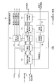
- the drive power supply device 1 includes a battery 2, relay units 3 and 14, an inverter 4, a motor 5, a capacitor 6, a current sensor 7, an angle sensor 8, a voltage sensor 9, a motor control device 10, and a vehicle control device 13.
- the battery 2 is a DC power source composed of a secondary battery or the like.
- the DC voltage of the battery 2 is supplied to the inverter 4 and the capacitor 6 via the relay unit 3.
- the relay unit 14 connected in parallel to the battery 2 is opened.
- the conduction between the relay units 3 and 14 is controlled by an ON / OFF operation (relay control signal) of a key switch operated by a driver via a vehicle control device 13 described later.
- the inverter 4 performs power conversion between the battery 2 and the motor 5.
- the inverter 4 converts the DC power supplied from the battery 2 into three phase voltages (U phase, V phase, W phase) and converts the three-phase AC power generated in the motor 5 into DC power.
- the inverter 4 includes a plurality of switching elements Tr1 to Tr6, a plurality of rectifier elements D1 to D6, and a gate drive circuit 41.
- the emitter electrode of the switching element Tr1 that connects the collector electrode to the positive electrode of the battery 2 and the collector electrode of the switching element Tr2 that connects the emitter electrode to the negative electrode of the battery 2 are connected to form an arm circuit.
- a connection point between a switching element Tr1 (hereinafter referred to as an upper arm) and Tr2 (hereinafter referred to as a lower arm) constituting the arm circuit is connected to a U-phase coil (not shown) of the motor 5.
- Rectifying elements D1 and D2 are connected to the upper arm Tr1 and the lower arm Tr2 in antiparallel directions, respectively.
- the upper arms Tr3 and Tr5 that connect the collector electrode to the positive electrode of the battery 2 and the lower arms Tr4 and Tr6 that connect the collector electrode to the negative electrode constitute an arm circuit similar to the upper arm Tr1 and the lower arm Tr2. Connection points of the respective arm circuits are connected to a V-phase coil and a W-phase coil, not shown, of the motor 5.
- the rectifying elements D3 to D6 are connected to the upper arms Tr3 and Tr5 and the lower arms Tr4 and Tr6 in antiparallel directions, respectively.
- a gate control signal generated based on a PWM signal output from the motor control device 10 is connected to each gate electrode of each of the switching elements Tr1 to Tr6 constituting the inverter 4.
- a gate control signal GUP is connected to the gate electrode of the upper arm Tr1.
- a gate control signal GUN is connected to the gate electrode of the lower arm Tr2.
- the gate control signal GVP is applied to the gate electrode of the upper arm Tr3
- the gate control signal GVN is applied to the gate electrode of the lower arm Tr4
- the gate control signal GWP is applied to the upper arm Tr5
- the gate control signal GWN is applied to the lower arm Tr6.
- the gate drive circuit 41 performs ON / OFF control of the upper arms Tr1, Tr3, Tr5 and the lower arms Tr2, Tr4, Tr6 at a predetermined timing based on the PWM signal input from the motor control device 10.
- the signals for ON / OFF control are the gate control signals GUP, GUN, GVP, GVN, GWP, and GWN.
- the predetermined timing is a cycle (hereinafter referred to as carrier cycle) in which the upper and lower arms Tr1 to Tr6 are ON / OFF controlled.
- the gate drive circuit 41 detects an overheat abnormality or an overcurrent abnormality state of each upper and lower arm and outputs an IGBT abnormality signal to the motor control device 10. Further, the gate drive circuit 41 converts the signal from the voltage sensor 9 that detects the voltage of the capacitor 6 that smoothes the voltage between the positive electrode and the negative electrode of the inverter 4 into an amplitude level that can be recognized by the motor control device 10. To the motor control device 10.
- the current sensor 7 outputs to the motor control device 10 a current sensor signal obtained by measuring the phase current flowing through the U-phase, V-phase, and W-phase coils. In addition, it is not necessary to provide the current sensors 7 in all three phases because the sum of the phase currents flowing through the respective phase coils becomes zero.
- the motor control device 10 controls the drive voltage supplied to the motor 5 with a PWM signal.
- the motor control device 10 includes angle information of a rotor (rotor) not shown in the motor 5, a current sensor signal (Iu, Iv, Iw), a capacitor voltage signal, a control start / stop signal, and a torque command.
- a PWM signal is generated based on the value T * .
- the PWM signal is a signal having the same pulse width and amplitude as the gate control signals GUP, GUN, GVP, GVN, GWP, and GWN. Note that U, V, and W are omitted when not particularly necessary, and are hereinafter referred to as gate control signals GP and GN.
- the control start / stop signal and the torque command value T * are input from the vehicle control device 13.
- the vehicle control device 13 includes a CPU, a ROM, and a RAM, and outputs a control start / stop signal when the key switch is turned on to start drive control of the electric vehicle. Further, the vehicle control device 13 calculates a torque command value T * based on the accelerator signal, the brake signal, and the shift position signal.
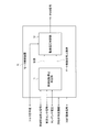
- a motor control device 10 according to the first embodiment will be described with reference to FIG.
- the motor control device 10 of the present embodiment includes a control start / stop determination unit 11 and a drive voltage control unit 12.
- the control start / stop determination unit 11 switches the state of the drive voltage supplied to the motor 5 to a stop state where control is stopped, a start state where control is being performed, or a start state.
- the drive voltage control unit 12 controls the drive voltage so that the phase current increases or decreases according to the elapsed time in the “start-up state”.
- the control start / stop determination unit 11 performs a control start / stop determination process of the motor control method according to the first embodiment. Moreover, the drive voltage control part 12 performs the drive voltage control process of the motor control method.
- FIG. 3 shows three states of the control start / stop determination unit 11: “control stop ⁇ (stop state)”, “control start ⁇ (start state)”, and “control start ⁇ (start state)”. Each state will be described with reference to the state transition diagram of FIG.
- Control stop ⁇ is a state in which the control of the inverter 4 is stopped.
- Control stop ⁇ is a state in which the output of the PWM signal is stopped, for example, when the electric vehicle is stopped, or when the rotational speed of the motor 5 is suddenly changed or the phase current is abnormal.
- Control start ⁇ is a state in which the inverter 4 is controlled according to the torque command value T * when the electric vehicle is running.
- Control start ⁇ is a state in which the inverter 4 is controlled by the PWM signal.
- Control start ⁇ is a state connecting “control stop ⁇ ” and “control start ⁇ ”.
- Control start ⁇ is a state in which the inverter 4 is controlled by a PWM signal different from the PWM signal in “control start ⁇ ”.
- control start ⁇ The state transition from “control stop ⁇ ” to “control start ⁇ ” occurs when the rotational speed of the motor 5 returns to less than a predetermined value. This is because when the number of rotations of the motor 5 after the return is lower than a predetermined value, the amount of overshoot becomes small without going through “control start ⁇ ”, so that “control stop ⁇ ” directly goes to “control start ⁇ ”. Transition.
- the control start / stop determination unit 11 determines “control start ⁇ ”
- the control start / stop determination unit 11 outputs a state signal indicating “control start ⁇ ” to the drive voltage control unit 12.
- control start / stop determination unit 11 determines “control stop ⁇ ”
- the control start / stop determination unit 11 outputs a state signal indicating “control stop ⁇ ” to the drive voltage control unit 12.
- the state transition from “control stop ⁇ ” to “control start ⁇ ” occurs when the number of revolutions of the motor 5 returns higher than a predetermined value. When the number of rotations of the motor 5 after the return is higher than a predetermined value, the amount of overshoot becomes large. Therefore, when returning from the “control stop ⁇ ” to the “control start ⁇ ”, the transition is made via the “control start ⁇ ”. .
- the control start / stop determination unit 11 determines “control start ⁇ ”
- the control start / stop determination unit 11 outputs a state signal indicating the state of “control start ⁇ ” to the drive voltage control unit 12.
- the determination of the state transition from “control stop ⁇ ” to “control start ⁇ ” can be performed based on a plurality of pieces of information. For example, when the change of the phase current when the control is resumed is large, when the rotational speed of the motor 5 is equal to or higher than a predetermined rotational speed, or when the temperature of the switching element of the inverter 4 is equal to or higher than the threshold value, etc. , Based on information such as rotation speed and temperature. Such information can be obtained from the current sensor signal, the rotor angle information, and the IGBT abnormality signal. The determination may be performed by using each piece of information individually or by combining a plurality of pieces of information. Further, the transition from “control activation ⁇ ” to “control start ⁇ ” may be performed based on each information.
- the state transition from “control start ⁇ ” to “control start ⁇ ” is performed, for example, when a predetermined time has elapsed since the transition to “control start ⁇ ”. Further, it is performed when the upper limit values (hereinafter referred to as gate control signal upper limit values) of the gate control signals GP and GN for turning on the upper and lower arms Tr1 to Tr6 reach a predetermined value.
- the mode (pulse width, amplitude) of the PWM signal is determined by the upper limit value of the gate control signal.
- the gate control signal upper limit value is output from the control start / stop determination unit 11 to the drive voltage control unit 12.
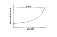
- FIG. 4 shows an example of a change in the gate control signal upper limit value.
- the horizontal axis in FIG. 4 represents the elapsed time since the transition to “control activation ⁇ ”, and the vertical axis represents, for example, the pulse width of the gate control signal upper limit value.
- the upper limit value corresponds to the elapsed time on a one-to-one basis and means that there is no larger size.
- the pulse width of the gate control signal upper limit value increases in accordance with the elapsed time from the transition to “control activation ⁇ ”.
- the pulse width of the gate control signal upper limit value increases linearly to, for example, a pulse width (predetermined value) corresponding to a duty ratio of 50% of the carrier period of the PWM signal.
- the drive voltage control unit 12 generates a PWM signal corresponding to the gate control signal upper limit value.
- the PWM signal is the same signal as the pulse width and amplitude of the gate control signals GP and GN as described above. Therefore, the motor control device 10 can control the magnitude of the phase current of the motor 5 by the PWM signal.
- the upper limit value of the gate control signal may be given to the drive voltage control unit 12. You can still do the same.
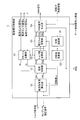
- FIG. 5 shows an example of the functional configuration of the drive voltage control unit 12 and the operation thereof will be described in more detail.
- the drive voltage controller 12 includes a voltage command value calculator 120, a current controller 121, a dq / 3-phase converter 122, a voltage / Duty converter 123, a PWM signal generator 124, a phase calculator 125, and a rotation speed calculator.
- the voltage command value calculation unit 120 uses the torque command value T * calculated by the vehicle control device 13 and the rotation speed ⁇ of the motor 5 calculated by the rotation speed calculation unit 126, and uses the d-axis current command value Id *. And the q-axis current command value Iq * are calculated.
- the d-axis current command value Id * and the q-axis current command value Iq * are d-axis and q-axis current values used in the current vector control method.
- the rotation speed calculator 126 calculates the rotation speed ⁇ of the motor 5 from the rotation phase ⁇ calculated by the phase calculator 125.
- the current control unit 121 receives a status signal input from the control start / stop determination unit 11, a d-axis current command value Id * , a q-axis current command value Iq *, and a three-phase / dq conversion unit 127.
- the d-axis voltage command value Vd * and the q-axis voltage command value Vq * are calculated using the d-axis current Id and the q-axis current Iq.
- Vd * and Vq * are calculated so that Id and Iq follow Id * and Iq * . That is, the drive voltage is determined so that the current measured by the current sensor follows the target current.
- both Vd * and Vq * are set to “0”. That is, the motor control device 10 of the present embodiment minimizes the influence on the phase current when transitioning to the “control start” state.
- the dq / 3-phase converter 122 converts the d-axis voltage command value Vd * and the q-axis voltage command value Vq * calculated by the current controller 121 into three phases based on the rotational phase ⁇ calculated by the phase calculator 125. Convert to AC voltage command values Vu * , Vv * , Vw * . The converted three-phase AC voltage command values Vu * , Vv * , Vw * are output to the PWM signal generation unit 124.
- the phase calculation unit 125 calculates the rotation phase ⁇ based on the rotor angle information from the angle sensor 8.
- the voltage / Duty conversion unit 123 is a duty signal Du * , which drives a three-phase switching element based on the three-phase AC voltage command values Vu * , Vv * , Vw * and a capacitor voltage signal which is a voltage of the capacitor 6. Dv * and Dw * are generated.
- the PWM signal generation unit 124 generates a PWM signal for controlling the inverter 4 based on the state signal, the gate control signal upper limit value, and the duty signals Du * , Dv * , Dw * .
- the pulse width of the PWM signal is determined by the upper limit value of the gate control signal. That is, in this embodiment, the mode of the PWM signal and the mode of the gate control signals GP and GN are the same.
- a signal input to the gate electrodes of the upper and lower arms Tr1 to Tr6 is referred to as a PWM signal.
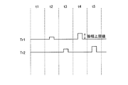
- FIG. 6 is a diagram showing PWM signals of the upper arm Tr1 and the lower arm Tr2 of the U phase.
- the PWM signals of the upper arm Tr1 and the lower arm Tr2 in the “control stop”, “control start”, and “control start” states from above are shown.
- the horizontal direction is time.
- both the upper arm Tr1 and the lower arm Tr2 are OFF.
- the upper and lower arms of the other phase are all OFF.
- Even in this “control stop” state when the electric vehicle is running, for example, the motor 5 is rotating, so that a back electromotive force is generated in the motor 5 due to a temporal change in the magnetic flux interlinking with each phase coil. To do.
- the phase current based on the back electromotive force flows to the battery 2 via the rectifying elements D1 to D6 connected to the upper and lower arms in antiparallel.
- the motor control device 10 literally does not control the motor 5.
- control start either the upper arm Tr1 or the lower arm Tr2 is always turned on.
- control start control of supplying a desired phase current to the motor 5 is performed by surely turning on one of the upper and lower arms.
- Control start is a state connecting “control stop” and “control start”.
- control activation the PWM signals of the upper arm Tr1 and the lower arm Tr2 change so that the upper limit value of the phase current increases in accordance with the elapsed time.
- the pulse width of the PWM signal is gradually increased according to the elapsed time.
- the maximum value (upper limit value) of the amplitude of the phase current can be gradually increased. The same applies to the other phases.
- the ON time of the lower arm Tr2 at time t3 is longer than the ON time of the upper arm Tr1 at time t2. Further, the ON time of the upper arm Tr1 at time t4 is longer than the ON time of the lower arm Tr2 at time t3. That is, the pulse width of the PWM signal increases corresponding to the change in the gate control signal upper limit value in FIG. When the pulse width of the PWM signal increases to a predetermined value, the state transitions to “control start”.
- FIG. 7 shows temporal changes in the phase current and torque when the state transitions from “control stop” ⁇ “control start” ⁇ “control start”.
- the amplitude of the phase current in the “control start” state gradually increases according to the elapsed time.
- the drive voltage control unit 12 controls the drive voltage supplied to the motor 5 so that the maximum value (upper limit value) of the amplitude of the phase current gradually increases.
- the drive voltage control unit 12 controls the drive voltage so that the maximum value (upper limit value) of the amplitude of the phase current gradually decreases according to the elapsed time.
- FIG. 8 shows a simulation result when the phase current is decreased.
- the drive voltage control unit 12 reduces overshoot and undershoot of the phase current.
- the mode of change of the maximum value (upper limit value) of the amplitude of the phase current is determined by the gate control signal upper limit value output by the control start / stop determination unit 11.
- the pulse width of the PWM signal gradually increases, so that there is no sudden change in the phase of the phase current. As a result, it is possible to suppress the jumping (falling) of the phase current called a secondary vibration system.
- the upper limit of the phase current is controlled to increase according to the elapsed time (FIGS. 7 and 8).
- the motor control device 10 of the present embodiment does not cause a device failure due to an excessive current. Further, torque fluctuation is not generated.
- FIG. 9 shows an example in which the amplitude of the PWM signal is increased according to the elapsed time in the “control start” state.
- the gate control signal upper limit value for changing the PWM signal has been described as an example in which the change rate is linearly changed with a constant change rate. However, as shown in FIG. 10, the change rate is gradually increased. Also good.
- the vertical and horizontal axes in FIG. 10 are the same as those in FIG.
- control start / stop determination unit 11 may be configured to switch to “control stop” when the phase current exceeds a threshold value.
- the control start / stop determination unit 11 changes the drive voltage state to the “control stop” state.
- the flow is shown.
- the drive voltage state transitions to the “control stop” state.
- the temperature of the switching elements Tr1 to Tr6 is equal to or higher than the threshold value (YES in step S11)
- the drive voltage state transitions to a “control stop” state.
- step S10 can be performed based on the phase current obtained from the current sensor, or may be performed based on the current command value that commands the target value. By making a transition to the “control stop” state with the phase current, it is possible to realize a motor control device that can detect an abnormal state of PWM control more quickly and stop PWM control accurately.
- the temperature of the switching elements Tr1 to Tr6 exceeds a threshold value, it can be obtained, for example, with the above-described IGBT abnormality signal.
- a threshold value By detecting the abnormal state of the PWM control depending on whether or not the temperature of the switching element exceeds the threshold value, it is possible to realize a motor control device that can prevent a failure of the switching element.
- control start / stop determination unit 11 may be configured to increase the time of the “control start” state as the phase current exceeding the threshold value increases.
- FIG. 12 shows an operation flow in which the length of time in the “control activation” state is changed in accordance with the magnitude of the phase current exceeding the threshold value.
- step S13 When the current value of the phase current exceeding the threshold is small (YES in step S13), the time during which the drive voltage is in the “control start” state is short (step S16). When the current value of the phase current exceeding the threshold value is medium (YES in step S14), the time during which the drive voltage is in the “control activation” state is medium (step S16). When the current value of the phase current exceeding the threshold is large (YES in step S15), the time during which the drive voltage is in the “control start” state is long (step S18).
- a motor control device 20 according to the second embodiment will be described with reference to FIG.
- the motor control device 20 of the present embodiment is different from the motor control device 10 (FIG. 2) in that it includes a voltage command value control unit 21 that controls a voltage command value in a “control stop” state.
- the drive voltage control unit 22 is different from the drive voltage control unit 12 in that a PWM signal is generated using the voltage command value (output of the voltage command value control unit 21).
- the voltage command value control unit 21 fixes the voltage command value for commanding increase / decrease of the phase current to a predetermined value in the “control stop” state. In other words, since the voltage command value is fixed to a predetermined value while the PWM control is stopped, it is possible to suppress fluctuations in the motor torque when transitioning from the “control stop” to the “control start” state.
- FIG. 14 shows a functional configuration example of the drive voltage control unit 22.
- the drive voltage control unit 22 differs from the drive voltage control unit 12 (FIG. 5) only in that a current control unit 221 is provided.
- the voltage command value while the PWM control is stopped is set to “0”.
- the current control unit 221 fixes the voltage command value whose status signal is “control stop” to a predetermined value.
- the predetermined values are, for example, the d-axis voltage command value Vd1 * and the q-axis voltage command value Vq1 newly calculated based on the torque command value T * , the rotational speed ⁇ , and the capacitor voltage in the “control stop” state. * It is good also. By newly calculating, even if the time of the “control stop” state is long, the motor torque can be made to follow the target value in a shorter time.
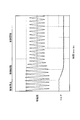
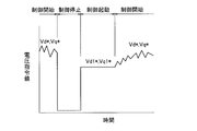
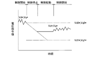
- FIG. 15 schematically shows the relationship between each state and the voltage command value when the new voltage designation values Vd1 * and Vq1 * are calculated in the “control stop” state.
- the horizontal axis is time, and the vertical axis is the voltage command value.
- the current control unit 121 calculates a new d-axis voltage command value Vd1 * and a q-axis voltage command value Vq1 * in the “control stop” state, and inputs the values to the current control unit 221. As a result, even when the “control stop” state is indefinitely long as indicated by a broken line, it is possible to suppress fluctuations in the motor torque when transitioning to the “control start” state.
- the predetermined value may be a voltage command value held by the voltage command value control unit 21 immediately before the transition to the “control stop” state.
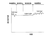
- FIG. 16 shows the relationship between each state and the voltage command value in that case.
- the horizontal and vertical axes in FIG. 16 are the same as those in FIG.
- the Vd * and Vq * prior to the transition to the state of the "control stop” the voltage command value control unit 21 holds as Vd0 * and Vq0 *.
- the change in the motor torque can be suppressed by inputting the voltage command value to the current control unit 221. This method is effective when the time of the “control stop” state is relatively short.
- the predetermined value depending on the length of time of the state of the "control stop”, "control stop” voltage command value controller 21 immediately before transition to a state of the holding Vd0 *, and Vq0 *, A value between Vd1 * and Vq1 * newly calculated and required for torque control is set.
- the voltage command value can be set appropriately, and fluctuations in motor torque when transitioning to the “control start” state can be suppressed.
- the motor control device 20 of the second embodiment it is possible to suppress fluctuations in the motor torque when transitioning from the “control stop” to the “control start” state. By suppressing the fluctuation of the motor torque, vibration based on the torque fluctuation is not generated.
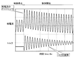
- FIG. 18 shows changes in phase current and torque over time when the motor 5 is driven by the motor control device of the comparative example and the state is changed from “control stop” to “control start”.
- the horizontal and vertical axes in FIG. 17 are the same as those in FIG.
- control start does not exist in the time change of the comparative example of FIG. That is, the state transitions from the “control stop” state to the “control start” state. Since the pulse width of the PWM signal when the PWM control is resumed is the same as that in the normal PWM control state and is wide, an overshoot may occur in the phase current depending on the rotation speed of the motor. As a result, vibration occurs in the motor torque.
- the motor control devices 10 and 20 of the present embodiment control the drive voltage so that the phase current increases or decreases according to the elapsed time when the drive voltage is in the activated state. Therefore, it is possible to reduce the overshoot of the phase current when the PWM control is restored, and to suppress the vibration generated in the motor torque.
- the PWM signals of the upper arm Tr1 and the lower arm Tr2 in the “control start” state are described as examples of inverted signals.
- a dead time in which the upper arm Tr1 and the lower arm Tr2 are simultaneously turned off is generally provided for each carrier cycle. In the description of the embodiment, the notation of dead time is omitted for the sake of simplicity.
- the motor 5 has been described as an example of a three-phase permanent magnet type synchronous motor for driving an electric vehicle, but is not limited to this example.
- the technical idea described in the above embodiment can be widely applied to motors such as actuators as well as driving (traveling) motors.
Priority Applications (11)
| Application Number | Priority Date | Filing Date | Title |
|---|---|---|---|
| EP15892600.6A EP3300246B1 (en) | 2015-05-21 | 2015-05-21 | Motor control device and motor control method |
| CA2986558A CA2986558C (en) | 2015-05-21 | 2015-05-21 | Motor control device and motor control method |
| US15/575,463 US10897220B2 (en) | 2015-05-21 | 2015-05-21 | Motor control device and motor control method |
| CN201580080213.2A CN107615643B (zh) | 2015-05-21 | 2015-05-21 | 电机控制装置和电机控制方法 |
| PCT/JP2015/064599 WO2016185601A1 (ja) | 2015-05-21 | 2015-05-21 | モータ制御装置とモータ制御方法 |
| RU2017144803A RU2657868C1 (ru) | 2015-05-21 | 2015-05-21 | Устройство управления электродвигателем и способ управления электродвигателем |
| MYPI2017704301A MY168995A (en) | 2015-05-21 | 2015-05-21 | Motor control device and motor control method |
| JP2017518701A JP6409966B2 (ja) | 2015-05-21 | 2015-05-21 | モータ制御装置とモータ制御方法 |
| KR1020177033289A KR101901544B1 (ko) | 2015-05-21 | 2015-05-21 | 모터 제어 장치와 모터 제어 방법 |
| BR112017024856-5A BR112017024856B1 (pt) | 2015-05-21 | 2015-05-21 | Dispositivo de controle de motor e método de controle de motor |
| MX2017014505A MX361836B (es) | 2015-05-21 | 2015-05-21 | Dispositivo de control de motor y método de control de motor. |
Applications Claiming Priority (1)
| Application Number | Priority Date | Filing Date | Title |
|---|---|---|---|
| PCT/JP2015/064599 WO2016185601A1 (ja) | 2015-05-21 | 2015-05-21 | モータ制御装置とモータ制御方法 |
Publications (1)
| Publication Number | Publication Date |
|---|---|
| WO2016185601A1 true WO2016185601A1 (ja) | 2016-11-24 |
Family
ID=57319626
Family Applications (1)
| Application Number | Title | Priority Date | Filing Date |
|---|---|---|---|
| PCT/JP2015/064599 WO2016185601A1 (ja) | 2015-05-21 | 2015-05-21 | モータ制御装置とモータ制御方法 |
Country Status (10)
| Country | Link |
|---|---|
| US (1) | US10897220B2 (zh) |
| EP (1) | EP3300246B1 (zh) |
| JP (1) | JP6409966B2 (zh) |
| KR (1) | KR101901544B1 (zh) |
| CN (1) | CN107615643B (zh) |
| BR (1) | BR112017024856B1 (zh) |
| CA (1) | CA2986558C (zh) |
| MX (1) | MX361836B (zh) |
| RU (1) | RU2657868C1 (zh) |
| WO (1) | WO2016185601A1 (zh) |
Families Citing this family (1)
| Publication number | Priority date | Publication date | Assignee | Title |
|---|---|---|---|---|
| CN115833684B (zh) * | 2021-12-15 | 2023-10-20 | 宁德时代新能源科技股份有限公司 | 永磁同步电机的转子温度的估算方法、装置和计算机设备 |
Citations (3)
| Publication number | Priority date | Publication date | Assignee | Title |
|---|---|---|---|---|
| JPH11252990A (ja) * | 1998-02-27 | 1999-09-17 | Fanuc Ltd | Pwm方式によるモータ制御装置 |
| JP2007104768A (ja) * | 2005-09-30 | 2007-04-19 | Nec Electronics Corp | モータ制御装置及びモータ制御方法 |
| JP2008271694A (ja) * | 2007-04-19 | 2008-11-06 | Rohm Co Ltd | モータ駆動回路、駆動方法およびそれを用いた冷却装置、電子計算機 |
Family Cites Families (21)
| Publication number | Priority date | Publication date | Assignee | Title |
|---|---|---|---|---|
| JP3226253B2 (ja) * | 1995-09-11 | 2001-11-05 | 株式会社東芝 | 永久磁石同期電動機の制御装置 |
| US6075328A (en) * | 1996-10-18 | 2000-06-13 | Hitachi, Ltd. | PWM/PAM control mode switching type motor control apparatus, and motor drive and air-conditioner using the same |
| RU2141719C1 (ru) * | 1998-03-25 | 1999-11-20 | Мищенко Владислав Алексеевич | Способ векторного управления синхронным электродвигателем с постоянными магнитами на роторе и электропривод для осуществления этого способа |
| JP3633531B2 (ja) * | 2001-08-28 | 2005-03-30 | トヨタ自動車株式会社 | 内燃機関の停止・始動制御装置 |
| RU2210172C2 (ru) * | 2001-09-28 | 2003-08-10 | ООО "НИИ автоматики и силовой электроники" | Способ управления синхронным двигателем в электромеханическом усилителе руля автомобиля |
| JP4789647B2 (ja) * | 2006-02-20 | 2011-10-12 | パナソニック株式会社 | モータ駆動装置 |
| EP2075906A4 (en) * | 2006-10-19 | 2013-09-11 | Mitsubishi Electric Corp | VECTOR CONTROL OF A PERMANENT MAGNET SYNCHRONOUS MOTOR |
| EP2194643B1 (en) * | 2007-09-25 | 2014-03-05 | Mitsubishi Electric Corporation | Controller for electric motor |
| JP4770883B2 (ja) * | 2008-06-25 | 2011-09-14 | 株式会社デンソー | 回転機の制御装置、及び回転機の制御システム |
| JP5252229B2 (ja) * | 2009-10-02 | 2013-07-31 | アイシン・エィ・ダブリュ株式会社 | 電動機駆動装置の制御装置 |
| JP5446921B2 (ja) * | 2010-01-22 | 2014-03-19 | マツダ株式会社 | 電気自動車の車両構造 |
| KR101628385B1 (ko) * | 2010-03-31 | 2016-06-08 | 현대자동차주식회사 | 영구자석 동기모터의 제어방법 |
| JP5857394B2 (ja) * | 2010-09-15 | 2016-02-10 | 日産自動車株式会社 | インバータ装置及びインバータ制御方法 |
| US8976560B2 (en) * | 2010-09-24 | 2015-03-10 | Nissan Motor Co., Ltd. | Inverter control device and inverter control method |
| JP5549505B2 (ja) * | 2010-09-28 | 2014-07-16 | 日産自動車株式会社 | 温度保護装置、モータ制御装置及び温度保護方法 |
| JP5906679B2 (ja) * | 2011-11-10 | 2016-04-20 | 富士電機株式会社 | 電力変換装置、および過電流保護回路 |
| JP5628233B2 (ja) * | 2012-03-15 | 2014-11-19 | 日立アプライアンス株式会社 | モータ駆動装置、流体圧縮システム、及び空気調和機 |
| CN103956861B (zh) * | 2014-04-19 | 2016-04-13 | 广东超力电机股份有限公司 | 微电机转子两端的风车片及换向器全自动装配机 |
| CN103956944A (zh) * | 2014-04-23 | 2014-07-30 | 上海理工大学 | 永磁同步电机带速启停控制系统及控制方法 |
| JP2017181805A (ja) * | 2016-03-30 | 2017-10-05 | 株式会社ジャパンディスプレイ | 表示装置、制御方法及び半導体装置 |
| JP2018046593A (ja) * | 2016-09-12 | 2018-03-22 | コニカミノルタ株式会社 | 永久磁石同期電動機の制御装置、制御方法、および画像形成装置 |
-
2015
- 2015-05-21 US US15/575,463 patent/US10897220B2/en active Active
- 2015-05-21 CN CN201580080213.2A patent/CN107615643B/zh active Active
- 2015-05-21 EP EP15892600.6A patent/EP3300246B1/en active Active
- 2015-05-21 KR KR1020177033289A patent/KR101901544B1/ko active IP Right Grant
- 2015-05-21 WO PCT/JP2015/064599 patent/WO2016185601A1/ja active Application Filing
- 2015-05-21 RU RU2017144803A patent/RU2657868C1/ru active
- 2015-05-21 CA CA2986558A patent/CA2986558C/en active Active
- 2015-05-21 MX MX2017014505A patent/MX361836B/es active IP Right Grant
- 2015-05-21 BR BR112017024856-5A patent/BR112017024856B1/pt active IP Right Grant
- 2015-05-21 JP JP2017518701A patent/JP6409966B2/ja active Active
Patent Citations (3)
| Publication number | Priority date | Publication date | Assignee | Title |
|---|---|---|---|---|
| JPH11252990A (ja) * | 1998-02-27 | 1999-09-17 | Fanuc Ltd | Pwm方式によるモータ制御装置 |
| JP2007104768A (ja) * | 2005-09-30 | 2007-04-19 | Nec Electronics Corp | モータ制御装置及びモータ制御方法 |
| JP2008271694A (ja) * | 2007-04-19 | 2008-11-06 | Rohm Co Ltd | モータ駆動回路、駆動方法およびそれを用いた冷却装置、電子計算機 |
Non-Patent Citations (1)
| Title |
|---|
| See also references of EP3300246A4 * |
Also Published As
| Publication number | Publication date |
|---|---|
| JPWO2016185601A1 (ja) | 2018-03-15 |
| KR101901544B1 (ko) | 2018-09-21 |
| EP3300246A1 (en) | 2018-03-28 |
| BR112017024856B1 (pt) | 2022-11-01 |
| US20180167014A1 (en) | 2018-06-14 |
| KR20170139085A (ko) | 2017-12-18 |
| CN107615643B (zh) | 2018-12-28 |
| CN107615643A (zh) | 2018-01-19 |
| CA2986558C (en) | 2018-05-29 |
| MX2017014505A (es) | 2018-03-01 |
| JP6409966B2 (ja) | 2018-10-24 |
| EP3300246A4 (en) | 2018-11-14 |
| BR112017024856A2 (pt) | 2018-08-07 |
| US10897220B2 (en) | 2021-01-19 |
| RU2657868C1 (ru) | 2018-06-18 |
| CA2986558A1 (en) | 2016-11-24 |
| EP3300246B1 (en) | 2020-04-29 |
| MX361836B (es) | 2018-12-18 |
Similar Documents
| Publication | Publication Date | Title |
|---|---|---|
| JP5138781B2 (ja) | 電力変換装置 | |
| US8310197B2 (en) | Control device for electric motor drive device | |
| JP4497235B2 (ja) | 交流電動機の制御装置および制御方法 | |
| US11211889B2 (en) | Motor system | |
| JP2013062970A (ja) | 回転電機制御システム | |
| JP2007143235A (ja) | 交流モータの駆動制御装置 | |
| JP2010114969A (ja) | 電力変換装置 | |
| JP6409966B2 (ja) | モータ制御装置とモータ制御方法 | |
| JP2005033932A (ja) | モータ制御装置 | |
| JP4007309B2 (ja) | モータ制御装置及びモータ制御方法 | |
| JP4784290B2 (ja) | モータ駆動装置 | |
| JP6776961B2 (ja) | インバータ制御装置及びインバータ制御方法 | |
| JP2005168140A (ja) | モータ制御装置及びその制御方法 | |
| JP3241252B2 (ja) | 交流モータ制御装置 | |
| JP2012090490A (ja) | モータ駆動制御システムの制御装置およびそれを搭載する車両 | |
| JP5325806B2 (ja) | 鉄道車両駆動制御装置 | |
| JP6681266B2 (ja) | 電動機の制御装置及びそれを備えた電動車両 | |
| JP2002051596A (ja) | 交流モーターの駆動制御装置 | |
| JP7196450B2 (ja) | モータシステム | |
| JP2023122381A (ja) | 駆動システム、制御装置 | |
| RU2419954C1 (ru) | Устройство управления электродвигателем | |
| JP2023081073A (ja) | 回転電機の制御装置、回転電機の制御方法、及び回転電機の制御プログラム | |
| JP2021197890A (ja) | 回転電機制御装置 | |
| JP2009207259A (ja) | モータ制御装置 | |
| JP2013074734A (ja) | モータ制御装置 |
Legal Events
| Date | Code | Title | Description |
|---|---|---|---|
| 121 | Ep: the epo has been informed by wipo that ep was designated in this application |
Ref document number: 15892600 Country of ref document: EP Kind code of ref document: A1 |
|
| ENP | Entry into the national phase |
Ref document number: 2017518701 Country of ref document: JP Kind code of ref document: A |
|
| WWE | Wipo information: entry into national phase |
Ref document number: MX/A/2017/014505 Country of ref document: MX |
|
| ENP | Entry into the national phase |
Ref document number: 20177033289 Country of ref document: KR Kind code of ref document: A |
|
| ENP | Entry into the national phase |
Ref document number: 2986558 Country of ref document: CA |
|
| WWE | Wipo information: entry into national phase |
Ref document number: 15575463 Country of ref document: US |
|
| NENP | Non-entry into the national phase |
Ref country code: DE |
|
| WWE | Wipo information: entry into national phase |
Ref document number: 2017144803 Country of ref document: RU |
|
| REG | Reference to national code |
Ref country code: BR Ref legal event code: B01A Ref document number: 112017024856 Country of ref document: BR |
|
| ENP | Entry into the national phase |
Ref document number: 112017024856 Country of ref document: BR Kind code of ref document: A2 Effective date: 20171121 |