EP3300246B1 - Motor control device and motor control method - Google Patents
Motor control device and motor control method Download PDFInfo
- Publication number
- EP3300246B1 EP3300246B1 EP15892600.6A EP15892600A EP3300246B1 EP 3300246 B1 EP3300246 B1 EP 3300246B1 EP 15892600 A EP15892600 A EP 15892600A EP 3300246 B1 EP3300246 B1 EP 3300246B1
- Authority
- EP
- European Patent Office
- Prior art keywords
- state
- control
- initiation
- motor
- drive voltage
- Prior art date
- Legal status (The legal status is an assumption and is not a legal conclusion. Google has not performed a legal analysis and makes no representation as to the accuracy of the status listed.)
- Active
Links
- 238000000034 method Methods 0.000 title claims description 14
- 230000000977 initiatory effect Effects 0.000 claims description 67
- 230000007704 transition Effects 0.000 claims description 46
- 230000007423 decrease Effects 0.000 claims description 12
- 230000003247 decreasing effect Effects 0.000 claims 2
- 238000010586 diagram Methods 0.000 description 12
- 230000005856 abnormality Effects 0.000 description 10
- 239000003990 capacitor Substances 0.000 description 8
- 230000000694 effects Effects 0.000 description 6
- 230000000052 comparative effect Effects 0.000 description 4
- 230000001360 synchronised effect Effects 0.000 description 3
- 230000002159 abnormal effect Effects 0.000 description 2
- 230000002547 anomalous effect Effects 0.000 description 2
- 238000006243 chemical reaction Methods 0.000 description 2
- 238000005259 measurement Methods 0.000 description 2
- 238000004088 simulation Methods 0.000 description 2
- 230000001419 dependent effect Effects 0.000 description 1
- 238000005265 energy consumption Methods 0.000 description 1
- 230000004907 flux Effects 0.000 description 1
Images


Classifications
-
- H—ELECTRICITY
- H02—GENERATION; CONVERSION OR DISTRIBUTION OF ELECTRIC POWER
- H02P—CONTROL OR REGULATION OF ELECTRIC MOTORS, ELECTRIC GENERATORS OR DYNAMO-ELECTRIC CONVERTERS; CONTROLLING TRANSFORMERS, REACTORS OR CHOKE COILS
- H02P21/00—Arrangements or methods for the control of electric machines by vector control, e.g. by control of field orientation
- H02P21/34—Arrangements for starting
-
- B—PERFORMING OPERATIONS; TRANSPORTING
- B60—VEHICLES IN GENERAL
- B60W—CONJOINT CONTROL OF VEHICLE SUB-UNITS OF DIFFERENT TYPE OR DIFFERENT FUNCTION; CONTROL SYSTEMS SPECIALLY ADAPTED FOR HYBRID VEHICLES; ROAD VEHICLE DRIVE CONTROL SYSTEMS FOR PURPOSES NOT RELATED TO THE CONTROL OF A PARTICULAR SUB-UNIT
- B60W10/00—Conjoint control of vehicle sub-units of different type or different function
- B60W10/04—Conjoint control of vehicle sub-units of different type or different function including control of propulsion units
- B60W10/08—Conjoint control of vehicle sub-units of different type or different function including control of propulsion units including control of electric propulsion units, e.g. motors or generators
-
- H—ELECTRICITY
- H02—GENERATION; CONVERSION OR DISTRIBUTION OF ELECTRIC POWER
- H02P—CONTROL OR REGULATION OF ELECTRIC MOTORS, ELECTRIC GENERATORS OR DYNAMO-ELECTRIC CONVERTERS; CONTROLLING TRANSFORMERS, REACTORS OR CHOKE COILS
- H02P1/00—Arrangements for starting electric motors or dynamo-electric converters
- H02P1/02—Details
- H02P1/04—Means for controlling progress of starting sequence in dependence upon time or upon current, speed, or other motor parameter
-
- H—ELECTRICITY
- H02—GENERATION; CONVERSION OR DISTRIBUTION OF ELECTRIC POWER
- H02P—CONTROL OR REGULATION OF ELECTRIC MOTORS, ELECTRIC GENERATORS OR DYNAMO-ELECTRIC CONVERTERS; CONTROLLING TRANSFORMERS, REACTORS OR CHOKE COILS
- H02P21/00—Arrangements or methods for the control of electric machines by vector control, e.g. by control of field orientation
- H02P21/06—Rotor flux based control involving the use of rotor position or rotor speed sensors
-
- H—ELECTRICITY
- H02—GENERATION; CONVERSION OR DISTRIBUTION OF ELECTRIC POWER
- H02P—CONTROL OR REGULATION OF ELECTRIC MOTORS, ELECTRIC GENERATORS OR DYNAMO-ELECTRIC CONVERTERS; CONTROLLING TRANSFORMERS, REACTORS OR CHOKE COILS
- H02P27/00—Arrangements or methods for the control of AC motors characterised by the kind of supply voltage
- H02P27/02—Arrangements or methods for the control of AC motors characterised by the kind of supply voltage using supply voltage with constant frequency and variable amplitude
-
- H—ELECTRICITY
- H02—GENERATION; CONVERSION OR DISTRIBUTION OF ELECTRIC POWER
- H02P—CONTROL OR REGULATION OF ELECTRIC MOTORS, ELECTRIC GENERATORS OR DYNAMO-ELECTRIC CONVERTERS; CONTROLLING TRANSFORMERS, REACTORS OR CHOKE COILS
- H02P27/00—Arrangements or methods for the control of AC motors characterised by the kind of supply voltage
- H02P27/04—Arrangements or methods for the control of AC motors characterised by the kind of supply voltage using variable-frequency supply voltage, e.g. inverter or converter supply voltage
- H02P27/06—Arrangements or methods for the control of AC motors characterised by the kind of supply voltage using variable-frequency supply voltage, e.g. inverter or converter supply voltage using dc to ac converters or inverters
- H02P27/08—Arrangements or methods for the control of AC motors characterised by the kind of supply voltage using variable-frequency supply voltage, e.g. inverter or converter supply voltage using dc to ac converters or inverters with pulse width modulation
- H02P27/085—Arrangements or methods for the control of AC motors characterised by the kind of supply voltage using variable-frequency supply voltage, e.g. inverter or converter supply voltage using dc to ac converters or inverters with pulse width modulation wherein the PWM mode is adapted on the running conditions of the motor, e.g. the switching frequency
-
- H—ELECTRICITY
- H02—GENERATION; CONVERSION OR DISTRIBUTION OF ELECTRIC POWER
- H02P—CONTROL OR REGULATION OF ELECTRIC MOTORS, ELECTRIC GENERATORS OR DYNAMO-ELECTRIC CONVERTERS; CONTROLLING TRANSFORMERS, REACTORS OR CHOKE COILS
- H02P29/00—Arrangements for regulating or controlling electric motors, appropriate for both AC and DC motors
- H02P29/02—Providing protection against overload without automatic interruption of supply
- H02P29/024—Detecting a fault condition, e.g. short circuit, locked rotor, open circuit or loss of load
- H02P29/027—Detecting a fault condition, e.g. short circuit, locked rotor, open circuit or loss of load the fault being an over-current
-
- H—ELECTRICITY
- H02—GENERATION; CONVERSION OR DISTRIBUTION OF ELECTRIC POWER
- H02P—CONTROL OR REGULATION OF ELECTRIC MOTORS, ELECTRIC GENERATORS OR DYNAMO-ELECTRIC CONVERTERS; CONTROLLING TRANSFORMERS, REACTORS OR CHOKE COILS
- H02P29/00—Arrangements for regulating or controlling electric motors, appropriate for both AC and DC motors
- H02P29/40—Regulating or controlling the amount of current drawn or delivered by the motor for controlling the mechanical load
Definitions
- the present invention relates to a motor control device and a motor control method which control a phase current of a motor by using a drive voltage supplied to the motor.
- PWM control Pulse Width Modulation
- a motor control device which determines that the motor control is unstable when a phase current flowing in at least one phase exceeds a predetermine value, and stops the PWM control (Patent Literature 1).
- the PWM control is resumed when the phase current falls below the predetermined value.
- Patent Literature 1 Japanese Patent Application Publication No. Hei 11-252990
- Prior art document CN 103 956 944 A discloses a system for controlling a start with speed and stop with speed of a permanent magnet synchronous motor.
- the motor can achieve smooth transition when it is started or stopped at a certain speed.
- the system is characterized by comprising a start and stop signal input portion, a computing portion, a storage portion, a judgment portion and a control portion, wherein the control portion is connected with the start and stop signal input portion, the computing portion, the storage portion and the judgment portion.
- the motor is controlled to adjust the current pulse width modulation value to a starting pulse width modulation value, so that a current control voltage value reaches a motor starting voltage value, and then the motor is started.
- the motor is controlled in order to slowly regulate a current pulse width modulation value to a stop pulse width modulation value, so that the current control voltage value reaches a motor stop voltage value. Then the motor is stopped.
- Prior art document EP 0 939 473 A2 proposes a motor controller for controlling currents flowing to a motor by the PWM system comprises interruption-restart control means for interrupting supply of PWM commands for at least one phase when the actual current flowing in at least one motor phase has exceeded a specified value, and for thereafter restarting PWM command supply.
- interruption-restart control means for interrupting supply of PWM commands for at least one phase when the actual current flowing in at least one motor phase has exceeded a specified value, and for thereafter restarting PWM command supply.
- control is performed to interrupt and restart supply of PWM commands.
- the current flowing to the motor is returned from an anomalous level to a normal level and the equipment protected.
- PWM command supply is resumed, normal control by PWM command is again performed, and a non-controlling state in the controller is avoided.
- Prior art document EP 0 837 549 A2 refers to a motor drive apparatus and an air-conditioner using a motor control apparatus having a feature to be able to gradually increase a dc voltage value to a predetermined value when starting the switching operation of a chopper circuit by means of the dc voltage control means thereof, and when stopping the switching operation of the chopper circuit to be able to gradually decrease the dc voltage value to a predetermined value. Further, the dc voltage command value is adjusted so as to be able to maintain a preferred value of dc voltage. Thereby, fluctuation in the number of revolutions of the motor can be prevented even if the converter is started or stopped while the motor is operating, thereby allowing the motor drive apparatus and air-conditioner using the motor control apparatus to be operated at their maximum capacities.
- Patent Literature 1 since the PWM control is resumed at the moment when the phase current falls below the predetermined value, overshoot may occur in the phase current just after the resuming and cause vibration in motor torque.
- the present invention has been made in view of the problem described above and an object thereof is to provide a motor control device and a motor control method which reduce overshoot of a phase current occurring at resuming of PWM control and thereby suppress vibration occurring in motor torque.
- a motor control device includes a control initiation-stop determiner and a drive voltage controller.
- the control initiation-stop determiner switches the state of the drive voltage to an initiation state during the transition from the stop state to the start state.
- the drive voltage controller controls the drive voltage such that the phase current increases or decreases in the initiation state as time elapses.
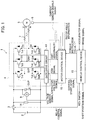
- Fig. 1 illustrates a configuration example of the drive power supply device 1 of an electric car which includes the motor control device 10 of the first embodiment.
- the drive power supply device 1 supplies drive power supply to a three-phase permanent magnet synchronous electric motor (hereafter, referred to as motor) which drives, for example, an electric vehicle such as a hybrid car or an electric car.
- motor three-phase permanent magnet synchronous electric motor
- the drive power supply device 1 includes a battery 2, relay units 3, 14, an inverter 4, a motor 5, a capacitor 6, current sensors 7, an angle sensor 8, a voltage sensor 9, the motor control device 10, and a vehicle control device 13.
- the battery 2 is a DC power supply consisting of a secondary cell and the like.
- the DC voltage of the battery 2 is supplied to the inverter 4 and the capacitor 6 via the relay unit 3.
- the relay unit 3 When the relay unit 3 is turned on, the relay unit 14 connected in parallel to the battery 2 is opened. Turn-on of the relay units 3, 14 is controlled by an ON/OFF operation (relay control signal) of a key switch operated by a driver, via the vehicle control device 13 to be described later.
- the inverter 4 performs power conversion between the battery 2 and the motor 5.
- the inverter 4 converts the DC power supplied from the battery 2 to three phase voltages (U phase, V phase, W phase) and converts three-phase AC power generated in the motor 5 to DC power.
- the inverter 4 includes multiple switching elements Tr1 to Tr6, multiple rectifying elements D1 to D6, and a gate drive circuit 41.
- An arm circuit is formed by connecting an emitter electrode of the switching element Tr1, having a collector electrode connected to a positive electrode of the battery 2, to a collector electrode of the switching element Tr2 having an emitter electrode connected to a negative electrode of the battery 2.
- a connection point of the switching elements Tr1 (hereafter, referred to as upper arm) and Tr2 (hereafter, referred to as lower arm) forming the arm circuit is connected to a not-illustrated U-phase coil of the motor 5.
- the rectifying elements D1 and D2 are connected respectively to the upper arm Tr1 and the lower arm Tr2 in an anti-parallel direction.
- the upper arms Tr3, Tr5, having collector electrodes connected to the positive electrode of the battery 2, and the lower arms Tr4, Tr6, having collector electrodes connected to the negative electrode of the battery 2, also form arms circuits like the upper arm Tr1 and the lower arm Tr2.
- the connection points in the respective arm circuits are connected respectively to not-illustrated V-phase coil and W-phase coil of the motor 5.
- the rectifying elements D3 to D6 are connected to the upper arms Tr3, Tr5 and the lower arms Tr4, Tr6 in the anti-parallel direction.
- Gate control signals generated based on a PWM signal outputted by the motor control device 10 are connected to gate electrodes of the switching elements Tr1 to Tr6 forming the inverter 4.
- a gate control signal GUP is connected to the gate electrode of the upper arm Tr1.
- a gate control signal GUN is connected to the gate electrode of the lower arm Tr2.
- a gate control signal GVP is connected to the gate electrode of the upper arm Tr3
- a gate control signal GVN is connected to the gate electrode of the lower arm Tr4
- a gate control signal GWP is connected to the upper arm Tr5, and a gate control signal GWN is connected to the lower arm Tr6.
- the gate drive circuit 41 controls ON/OFF of the upper arms Tr1, Tr3, Tr5 and the lower arms Tr2, Tr4, Tr6 at predetermined timing, based on the PWM signal received from the motor control device 10.
- Signals for ON/OFF control are the gate control signals GUP, GUN, GVP, GVN, GWP, GWN described above.
- the predetermined timing is a cycle (hereafter, referred to as carrier cycle) of ON/OFF control of the upper and lower arms Tr1 to Tr6.
- the gate drive circuit 41 detects overheat abnormality and overcurrent abnormality states in the upper and lower arms and outputs an IGBT abnormality signal to the motor control device 10. Furthermore, the gate drive circuit 41 converts a signal from the voltage sensor 9 to a signal with an amplitude level recognizable by the motor control device 10 and outputs the converted signal to the motor control device 10, the voltage sensor 9 configured to detect the voltage of the capacitor 6 which smooths the voltage between the positive electrode and the negative electrode of the inverter 4.
- the current sensors 7 output current sensor signals obtained by measuring phase currents flowing respectively through the U-phase coil, the V-phase coil, and the W-phase coil, to the motor control device 10. Note that, since the total of the phase currents flowing through the respective coils is zero, there is no need to provide the current sensors 7 for all three phases.
- the motor control device 10 controls a drive voltage supplied to the motor 5 by using the PWM signal.
- the motor control device 10 generates the PWM signal based on angle information of a not-illustrated rotor of the motor 5, the current sensor signals (Iu, Iv, Iw), a capacitor voltage signal, a control start-stop signal, and a torque instruction value T*.
- the PWM signal is a signal with the same pulse width and the same amplitude as the gate control signals GUP, GUN, GVP, GVN, GWP, GWN described above. Note that, notation of U, V, W is omitted when it is unnecessary, and the gate control signals are noted as gate control signals GP, GN hereafter.
- the motor control device 10 receives the control start-stop signal and the torque instruction value T* from the vehicle control device 13.
- the vehicle control device 13 includes a CPU, a ROM, and a RAM, and outputs the control start-stop signal in response to the ON operation of the key switch to start drive control of the electric vehicle. Moreover, the vehicle control device 13 calculates the torque instruction value T* based on an accelerator signal, a brake signal, and a shift position signal.
- the motor control device 10 according to the first embodiment is described with reference to Fig. 2 .
- the motor control device 10 of the embodiment includes a control initiation-stop determiner 11 and a drive voltage controller 12.
- the control initiation-stop determiner 11 switches a state of the drive voltage supplied to the motor 5 to a stop state in which the control is stopped, a start state in which the control is executed, or an initiation state.
- the drive voltage controller 12 controls the drive voltage such that the phase currents increase or decrease as the time elapses.
- control initiation-stop determiner 11 performs a control initiation-stop determination step in a motor control method according to the first embodiment.
- drive voltage controller 12 performs a drive voltage control step in the motor control method.
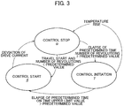
- Fig. 3 illustrates three states of the control initiation-stop determiner 11 which are "control stop ⁇ (stop state),” “control start ⁇ (start state),” and “control initiation ⁇ (initiation state).”
- the states are described with reference to the state transition diagram of Fig. 3 .
- control stop ⁇ is a state in which the control of the inverter 4 is stopped.
- control stop ⁇ is a state in which the output of the PWM signal is stopped, for example, when the electric vehicle is stopped or when there occurs an abnormality in the phase currents or an abrupt change in the number of revolutions of the motor 5.
- control start ⁇ is a state in which the inverter 4 is controlled according to the torque instruction value T* during the traveling of the electric vehicle or the like.
- control start ⁇ is a state in which the inverter 4 is controlled by using the PWM signal.
- control initiation ⁇ is a state connecting the "control stop ⁇ " and the “control start ⁇ .”
- control initiation ⁇ is a state in which the inverter 4 is controlled by using a PWM signal different from the PWM signal used in the "control start ⁇ .”
- a state transition from the "control stop ⁇ " to the "control start ⁇ " is performed when the number of revolutions of the motor 5 is to return to a value lower than a predetermined value. This is because, when the number of revolutions of the motor 5 after the return is lower than the predetermined value, an amount of overshoot is small even without transition to the "control initiation ⁇ .” Accordingly, the direct transition from the "control stop ⁇ " to the "control start ⁇ " is performed.
- the control initiation-stop determiner 11 determines to perform transition to the "control start ⁇ ”
- the control initiation-stop determiner 11 outputs a state signal indicating the "control start ⁇ " to the drive voltage controller 12.
- a state transition from the "control start ⁇ " to the "control stop ⁇ " is performed, for example, when abnormality in the phase currents occurs.
- the control initiation-stop determiner 11 determines to perform transition to the "control stop ⁇ ”
- the control initiation-stop determiner 11 outputs a state signal indicating the "control stop ⁇ " to the drive voltage controller 12.
- a state transition from the "control stop ⁇ " to the "control initiation ⁇ " is performed when the number of revolutions of the motor 5 is to return to a value higher than the predetermined value. Since the overshoot amount is large when the number of revolutions of the motor 5 after the return is higher than the predetermined value, the transition is performed in this case such that the state returns from the "control stop ⁇ " to the "control start ⁇ " via the "control initiation ⁇ .”
- the control initiation-stop determiner 11 determines to perform transition to the "control initiation ⁇ ”
- the control initiation-stop determiner 11 outputs a state signal indicating the "control initiation ⁇ " state to the drive voltage controller 12.
- the determination of the state transition from the "control stop ⁇ " to the "control initiation ⁇ " can be performed based on multiple pieces of information. For example, the determination is performed based on pieces of information such as the phase currents, the number of revolutions, and the temperatures such that the state transition is performed when changes in the phase currents at the time of resuming the control are large, when the number of revolutions of the motor 5 is equal to or more than the predetermined number of revolutions, when the temperature of the switching elements in the inverter 4 is equal to or more than a threshold, or in similar cases.
- Piece of information can be obtained from the current sensor signals, the rotor angle information, and the IGBT abnormality signal.
- the determination may be performed by using the pieces of information independently or by combining multiple pieces of information.
- the transition from the "control initiation ⁇ " to the "control start ⁇ " may also be performed based on the pieces of information.
- the state transition from the "control initiation ⁇ " to the "control start ⁇ " is performed, for example, when a predetermined time elapses from the moment of transition to the "control initiation ⁇ .” Moreover, the state transition is performed when the upper limit value of the gate control signals GP, GN (hereafter, referred to as gate control signal upper limit value) for turning ON the upper and lower arms Tr1 to Tr6 reaches a predetermined value.
- the gate control signal upper limit value determines the mode (pulse width, amplitude) of the PWM signal.
- the gate control signal upper limit value is outputted from the control initiation-stop determiner 11 to the drive voltage controller 12.
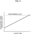
- Fig. 4 illustrates an example of a change of the gate control signal upper limit value.
- the horizontal axis of Fig. 4 represents a time elapsed from the transition to the "control initiation ⁇ " and the vertical axis of Fig. 4 represents, for example, the pulse width at the gate control signal upper limit value.
- the upper limit value is in one-to-one correspondence with the elapsed time, and means that there is no value greater than the upper limit.
- the pulse width at the gate control signal upper limit value is increased as the time elapses from the transition to the "control initiation ⁇ ."
- the pulse width at the gate control signal upper limit value is increased linearly to, for example, a pulse width (predetermined value) corresponding to a duty ratio of 50% of the carrier cycle of the PWM signal.
- the drive voltage controller 12 generates the PWM signal corresponding to the gate control signal upper limit value.
- the PWM signal is a signal with the same pulse width and the same amplitude as the gate control signals GP, GN as described above. Accordingly, the motor control device 10 can control the magnitudes of the phase currents of the motor 5 by using the PWM signal.
- drive voltage controller 12 may hold the gate control signal upper limit value. Similar operations can be performed also in this case.
- Fig. 5 illustrates a functional configuration example of the drive voltage controller 12, and operations thereof are described in further detail.
- the drive voltage controller 12 includes a current instruction value calculator 120, a current controller 121, a d-q/three-phase converter 122, a voltage/Duty converter 123, a PWM signal generator 124, a phase calculator 125, a number-of-revolutions calculator 126, and a three-phase/d-q converter 127.
- the current instruction value calculator 120 calculates a d-axis current instruction value Id* and a q-axis current instruction value Iq* by using the torque instruction value T* calculated by the vehicle control device 13 and the number of revolutions ⁇ of the motor 5 calculated by the number-of-revolutions calculator 126.
- the d-axis current instruction value Id* and the q-axis current instruction value Iq* are current values of the d-axis and the q-axis used in a current vector control method.
- the number-of-revolutions calculator 126 calculates the number of revolutions ⁇ of the motor 5 from a rotation phase ⁇ calculated by the phase calculator 125.
- the current controller 121 calculates a d-axis voltage instruction value Vd* and a q-axis voltage instruction value Vq* by using the state signal received from the control initiation-stop determiner 11, the d-axis current instruction value Id*, the q-axis current instruction value Iq*, and a d-axis current Id and a q-axis current Iq received from the three-phase/d-q converter 127.
- Vd* and Vq* are calculated such that Id and Iq follow the Id* and Iq*.
- the drive voltages are determined such that the currents measured by the current sensors follow the target currents.
- Vd* and Vq* are both set to "0." Specifically, the motor control device 10 of the embodiment minimizes an effect on the phase currents in the transition to the "control initiation” state.
- the d-q/three-phase converter 122 converts the d-axis voltage instruction value Vd* and the q-axis voltage instruction value Vq* calculated by the current controller 121 to three-phase AC voltage instruction values Vu*, Vv*, Vw*, based on the rotation phase ⁇ calculated by the phase calculator 125.
- the three-phase AC voltage instruction values Vu*, Vv*, Vw* obtained by the conversion are outputted to the PWM signal generator 124.
- the phase calculator 125 calculates the rotation phase ⁇ based on the rotor angle information from the angle sensor 8.
- the voltage/Duty converter 123 generates duty signals Du*, Dv*, Dw* which drive the three-phase switching elements, based on the three-phase AC voltage instruction values Vu*, Vv*, Vw* and the capacitor voltage signal being the voltage of the capacitor 6.
- the PWM signal generator 124 generates the PWM signal used to control the inverter 4, based on the state signal, the gate control signal upper limit value, and the duty signals Du*, Dv*, Dw*. In this case, the pulse width of the PWM signal is determined by the gate control signal upper limit value. In other words, in the embodiment, the mode of the PWM signal and the modes of the gate control signals GP, GN are the same. In the following description, the signals inputted into the gate electrodes of the upper and lower arms Tr1 to Tr6 are referred to as PWM signal.
- Fig. 6 is a diagram illustrating the PWM signals for the upper arm Tr1 and the lower arm Tr2 of the U phase.
- Fig. 6 illustrates the PWM signals for the upper arm Tr1 and the lower arm Tr2 in the states of "control stop,” “control initiation,” and “control start” from the top.
- the horizontal direction represents time.
- the upper arm Tr1 and the lower arm Tr2 are both OFF.
- the upper and lower arms of the other phases are also all OFF.
- the motor 5 is rotating, so even if it is the "control stop” state, counter electromotive force is generated in the motor 5 due to change over time in a magnetic flux interlinking with each phase coil.
- the phase current based on this counter electromotive force flows into the battery 2 via the rectifying elements D1 to D6 connected in anti-parallel to the upper and lower arms.
- the motor control device 10 literally does not control the motor 5.
- the “control initiation” is the state connecting the “control stop” and the “control start.”
- the PWM signals for the upper arm Tr1 and the lower arm Tr2 are changed such that the upper limit value of the phase current increases as the time elapses.
- the pulse width of the PWM signal is gradually increased as the time elapses.
- the maximum value (upper limit value) of the amplitude of the phase current can be gradually increased. This is the same for the other phases.
- the ON duration of the lower arm Tr2 in time t3 is longer than the ON duration of the upper arm Tr1 in time t2.
- the ON duration of the upper arm tr1 in time t4 is longer than the ON duration of the lower arm Tr2 in the time t3.
- the pulse width of each PWM signal increases depending on the change of the gate control signal upper limit value in Fig. 4 . Then, when the pulse width of each PWM signal increases to a predetermined value, the state transitions to the "control start.”
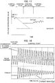
- Fig. 7 illustrates a result of simulation of the phase current in the case where the motor control device 10 of the embodiment controls the motor 5.
- Fig. 7 illustrates changes in the phase current and the torque over time in the case where the state transitions from the "control stop” to the "control initiation” and then to the "control start.”
- the amplitude of the phase current in the "control initiation" state gradually increases as the time elapses.
- the drive voltage controller 12 controls the drive voltage supplied to the motor 5 such that the maximum value (upper limit value) of the amplitude of the phase current gradually increases.
- the drive voltage controller 12 controls the drive voltage such that the maximum value (upper limit value) of the amplitude of the phase current gradually decreases as the time elapses.
- Fig. 8 illustrates a simulation result of the case where the phase current is reduced.
- the drive voltage controller 12 reduces the overshoot and the undershoot of the phase current as described above.
- the change mode of the maximum value (upper limit value) of the phase current amplitude is determined by the gate control signal upper limit value outputted by the control initiation-stop determiner 11.
- control initiation the control is performed such that the upper limit of the phase current increases as the time elapses ( Figs. 7 and 8 ).
- the motor control device 10 of the embodiment thus prevents occurrence of device failure due to an excessive current. Moreover, the motor control device 10 also prevents torque fluctuation.
- Fig. 9 illustrates an example in which the amplitude of the PWM signal is increased in the "control initiation" state as the time elapses.
- the amplitude of the PWM signal for each of the upper arm Tr1 and the lower arm Tr2 increases to match an amplitude upper limit value determined for each elapsed time. The same applies to the P phase and the W phase.
- a motor control device having the same effects as in the aforementioned case of controlling the pulse width can be achieved also by changing the amplitude of the PWM signal as described above. Moreover, similar effects can be obtained also by changing both of the pulse width and the amplitude simultaneously.
- the change rate may be gradually increased as illustrated in Fig. 10 .
- the vertical and horizontal axes in Fig. 10 are the same as those in Fig. 4 .
- the change of the phase current in the "control initiation" state can be made smoother by increasing the change rate of the gate control signal upper limit value as the time elapses as illustrated in Fig. 10 . As a result, abrupt rise (fall) of the phase current can be surely reduced.
- control initiation-stop determiner 11 may be configured to switch to the "control stop” when a phase current exceeds a threshold.
- Fig. 11 illustrates an operation flow in which the control initiation-stop determiner 11 switches the state of the drive voltage to the "control stop” state when the phase current exceeds the threshold and when the temperature of the switching elements Tr1 to Tr6 exceeds a threshold.
- the measurement value of the phase current reaches or exceeds the threshold (YES in step S10)
- the state of the drive voltage is transitioned to the "control stop” state.
- the temperature of the switching elements Tr1 to Tr6 reaches or exceeds the threshold (YES in step S11)
- the state of the drive voltage is transitioned to the "control stop” state.
- step S10 may be performed by using the phase current obtained from each current sensor or by using values such as a current instruction value instructing the aforementioned target value.
- a motor control device which can detect an abnormal state of the PWM control more quickly and stop the PWM control accurately can be achieved by performing transition to the "control stop" state based on the phase current.
- the temperature of the switching elements Tr1 to Tr6 exceeding the threshold can be detected by using, for example, the aforementioned IGBT abnormality signal.
- a motor control device which can prevent failure of the switching elements can be achieved by detecting an abnormal state of the PWM control based on whether the temperature of the switching elements has exceeded the threshold or not.
- Actively stopping the PWM control when abnormality in the phase current or the temperature is detected as described above can also suppress energy consumption. In other words, wasteful consumption of energy can also be prevented.
- control initiation-stop determiner 11 may be configured to set the duration of the "control initiation” state such that the larger the phase current exceeding the threshold is the longer the duration of the "control initiation” state is.
- Fig. 12 illustrates an operation flow in which the length of the duration of the "control initiation” state is changed depending on the magnitude of the phase current exceeding the threshold.
- step S16 When the current value of the phase current exceeding the threshold is low (YES in step S13), the duration in which the state of the drive voltage is set to the "control initiation” state is short (step S16).
- the duration in which the state of the drive voltage is set to the "control initiation” state is an intermediate length (step S16).
- step S15 When the current value of the phase current exceeding the threshold is high (YES in step S15), the duration in which the state of the drive voltage is set to the "control initiation” state is long (step S18).
- the duration in the "control initiation state” is set such that the larger the phase current exceeding the threshold is, the longer the duration in the "control initiation state” is, the time taken to resume the PWM control can be set such that the higher the phase current is, the longer the time taken to resume the PWM control is. Accordingly, a motor control device which can stabilize the resuming of the PWM control can be achieved.
- a motor control device which can stabilize the resuming of the PWM control can be achieved by setting the time taken to transition to the "control start” state such that the higher the temperature of the switching elements is, the longer the time taken to transition to the "control start” state is.
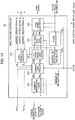
- the motor control device 20 of the embodiment is different from the motor control device 10 ( Fig. 2 ) in that the motor control device 20 includes a voltage instruction value controller 21 configured to control voltage instruction values in the "control stop" state.
- a drive voltage controller 22 is different from the drive voltage controller 12 in that the drive voltage controller 22 generates the PWM signal by using these voltage instruction values (outputs of the voltage instruction value controller 21).
- the voltage instruction value controller 21 fixes each of the voltage instruction values instructing increase or decrease of the phase currents to a predetermined value in the "control stop” state. Specifically, since the voltage instruction value is fixed to the predetermined value while the PWM control is stopped, fluctuation of the motor torque in the transition from the "control stop” state to the "control initiation” state can be suppressed.
- Fig. 14 illustrates a functional configuration example of the drive voltage controller 22.
- the drive voltage controller 22 is different from the drive voltage controller 12 ( Fig. 5 ) only in that the drive voltage controller 22 includes a current controller 221.
- the voltage instruction value in the period when the PWM control is stopped is set to "0."
- the state signal fixes the voltage instruction value in the "control stop" to the predetermined value.
- the predetermined value may be, for example, a d-axis voltage instruction value Vd1* and a q-axis voltage command value Vq1* newly calculated based on the torque instruction value T*, the number of revolutions co, and the capacitor voltage in the "control stop” state. Newly calculating the values allows the motor torque to follow the target value more quickly even when the duration of the "control stop" state is long.
- Fig. 15 schematically illustrates a relationship between the voltage instruction value and each of the states in the case where the new voltage instruction values Vd1*, Vq1* are calculated in the "control stop" state.
- the horizontal axis represents time and the vertical axis represents the voltage instruction value.
- the voltage instruction value controller 21 calculates the new d-axis voltage instruction value Vd1* and the new q-axis voltage command value Vq1* in the "control stop” state, and inputs these values into the current controller 221. As a result, fluctuation of the motor torque in the transition to the "control initiation” state can be suppressed even when the "control stop” state is infinitely long as illustrated by the broken line.
- the predetermined value may be the voltage instruction value held by the voltage instruction value controller 21 just before the transition to the "control stop" state.
- a relationship between the voltage instruction value and each state in this case is illustrated in Fig. 16 .
- the horizontal axis and the vertical axis of Fig. 16 are the same as those of Fig. 15 .
- the voltage instruction value controller 21 holds Vd* and Vq* just before the transition to the "control stop” state as Vd0* and Vq0*.
- the voltage instruction values thus held are inputted into the current controller 221 when the state transitions to the "control initiation" state to suppress fluctuation of the motor torque. This method is effective when the duration of the "control stop" state is relatively short.
- the predetermined value may be set, depending on the length of the duration of the "control stop” state, to a value between the voltage instruction value Vd0*, Vq0* held just before the transition to the "control stop” state and the voltage instruction value Vd1*, Vq1* newly calculated by using the torque instruction value T* required for the torque control.
- Fig. 17 schematically illustrates a relationship between the voltage instruction value and each state in the case where the predetermined value is set to a value between the held voltage instruction value Vd0*, Vq0* and the newly-calculated voltage instruction value Vd1*, Vq1*.
- the horizontal axis and the vertical axis of Fig. 17 are the same as those of Fig. 15 .
- the voltage command values Vd* and Vq* in the transition to the "control stop” state are each set to a value between Vd0*, Vq0* and Vd1*, Vq1* depending on the length of the duration of the "control stop” state.
- the duration of the "control stop” state in the case of using newly-calculated Vd1*, Vq1* is determined in advance and the value is determined from the proportional relationship between this time and the actual duration of the "control stop” state.
- the predetermined value is set, depending on the length of the duration of the "control stop” state, to a value between Vd0*, Vq0* held by the voltage instruction value controller 21 just before the transition to the "control stop” state and newly-calculated Vd1*, Vq1* required for the torque control.
- Vd0*, Vq0* held by the voltage instruction value controller 21 just before the transition to the "control stop” state
- Vd1*, Vq1* required for the torque control As a result, it is possible to appropriately set the voltage instruction value and suppress fluctuation of the motor torque in the transition to the "control initiation" state.
- the motor control device 20 of the second embodiment can suppress fluctuation of the motor torque in the transition from the "control stop” state to the "control initiation” state. Suppressing the fluctuation of the motor torque can prevent occurrence of vibration based on torque fluctuation.
- Fig. 18 illustrates changes in the phase current and the torque over time in the case where the motor 5 is driven by a motor control device of a comparative example and the state is transitioned from the "control stop” state to the "control start” state.
- the horizontal axis and the vertical axis of Fig. 17 are the same as those of Fig. 7 .
- the torque vibration occurs as soon as the state transitions from the "control stop” state to the "control start” state.
- the vibration continues for 30 ms or more.
- no vibration occurs in the same situation ( Fig. 7 ).
- the motor control devices 10 and 20 in the embodiments control the drive voltage such that each phase current increases or decreases as the time elapses in the situation where the state of the drive voltage is the initiation state. Accordingly, the motor control devices 10 and 20 can reduce overshoot of the phase current and suppress vibration occurring in the motor torque in the case where the PWM control is resumed.
- the present invention is not limited to this example.
- the technical idea described in the aforementioned embodiments can be applied not only to a motor for driving (traveling) but also to a wide variety of motors such as an actuator.
Description
- The present invention relates to a motor control device and a motor control method which control a phase current of a motor by using a drive voltage supplied to the motor.
- Conventionally, among motor control devices which control phase currents supplied to a motor by using a PWM (Pulse Width Modulation) method (hereafter, referred to as PWM control), there is known a motor control device which determines that the motor control is unstable when a phase current flowing in at least one phase exceeds a predetermine value, and stops the PWM control (Patent Literature 1). In the method disclosed in
Patent Literature 1, the PWM control is resumed when the phase current falls below the predetermined value. - Patent Literature 1: Japanese Patent Application Publication No.
Hei 11-252990 - Prior art document
CN 103 956 944 A discloses a system for controlling a start with speed and stop with speed of a permanent magnet synchronous motor. The motor can achieve smooth transition when it is started or stopped at a certain speed. The system is characterized by comprising a start and stop signal input portion, a computing portion, a storage portion, a judgment portion and a control portion, wherein the control portion is connected with the start and stop signal input portion, the computing portion, the storage portion and the judgment portion. When it is judged that the motor cannot conduct smooth start, the motor is controlled to adjust the current pulse width modulation value to a starting pulse width modulation value, so that a current control voltage value reaches a motor starting voltage value, and then the motor is started. When it is judged that the motor cannot conduct a smooth stop, the motor is controlled in order to slowly regulate a current pulse width modulation value to a stop pulse width modulation value, so that the current control voltage value reaches a motor stop voltage value. Then the motor is stopped. - Prior art document
EP 0 939 473 A2 proposes a motor controller for controlling currents flowing to a motor by the PWM system comprises interruption-restart control means for interrupting supply of PWM commands for at least one phase when the actual current flowing in at least one motor phase has exceeded a specified value, and for thereafter restarting PWM command supply. When the actual current flowing to the motor has reached a previously determined anomalous level, control is performed to interrupt and restart supply of PWM commands. By interrupting the supply of the PWM commands, the current flowing to the motor is returned from an anomalous level to a normal level and the equipment protected. After the motor current is returned to a normal level by the interruption of PWM command supply, PWM command supply is resumed, normal control by PWM command is again performed, and a non-controlling state in the controller is avoided. - Prior art document
EP 0 837 549 A2 refers to a motor drive apparatus and an air-conditioner using a motor control apparatus having a feature to be able to gradually increase a dc voltage value to a predetermined value when starting the switching operation of a chopper circuit by means of the dc voltage control means thereof, and when stopping the switching operation of the chopper circuit to be able to gradually decrease the dc voltage value to a predetermined value. Further, the dc voltage command value is adjusted so as to be able to maintain a preferred value of dc voltage. Thereby, fluctuation in the number of revolutions of the motor can be prevented even if the converter is started or stopped while the motor is operating, thereby allowing the motor drive apparatus and air-conditioner using the motor control apparatus to be operated at their maximum capacities. - However, in
Patent Literature 1, since the PWM control is resumed at the moment when the phase current falls below the predetermined value, overshoot may occur in the phase current just after the resuming and cause vibration in motor torque. - The present invention has been made in view of the problem described above and an object thereof is to provide a motor control device and a motor control method which reduce overshoot of a phase current occurring at resuming of PWM control and thereby suppress vibration occurring in motor torque.
- The object underlying the present invention is achieved by a motor control device and method according to
independent claim - A motor control device according to one aspect of the present invention includes a control initiation-stop determiner and a drive voltage controller. When a state of a drive voltage supplied to a motor is to be transitioned from a stop state in which control of the drive voltage is stopped to a start state in which the control is executed, the control initiation-stop determiner switches the state of the drive voltage to an initiation state during the transition from the stop state to the start state. The drive voltage controller controls the drive voltage such that the phase current increases or decreases in the initiation state as time elapses.
-
- [
Fig. 1] Fig. 1 is a diagram illustrating a configuration example of a drivepower supply device 1 for an electric car. - [
Fig. 2] Fig. 2 is a diagram illustrating a functional configuration example of amotor control device 10 in a first embodiment. - [
Fig. 3] Fig. 3 is a diagram illustrating an example of state transition of themotor control device 10. - [
Fig. 4] Fig. 4 is a graph illustrating an example of a change of a gate control signal upper limit value in a control initiation state. - [
Fig. 5] Fig. 5 is a diagram illustrating a functional configuration example of adrive voltage controller 12. - [
Fig. 6] Fig. 6 a diagram illustrating an example of a PWM signal in each of states of control stop, control initiation, and control start. - [
Fig. 7] Fig. 7 is a graph illustrating an example of a change of a phase current in the case where themotor control device 10 controls amotor 5. - [
Fig. 8] Fig. 8 is a graph illustrating another example of the change of the phase current in the case where themotor control device 10 controls themotor 5. - [
Fig. 9] Fig. 9 is a diagram illustrating an example in which the amplitude of the PWM signal is increased in the initiation state. - [
Fig. 10] Fig. 10 is a graph illustrating another example of the change of the gate control signal upper limit value in the control initiation state. - [
Fig. 11] Fig. 11 is a diagram illustrating part of an operation flow in which a control initiation-stop determiner 11 performs determination on the "control stop" state. - [
Fig. 12] Fig. 12 is a diagram illustrating part of an operation flow in which a control initiation-stop determiner 11 performs determination on the "control start" state. - [
Fig. 13] Fig. 13 is a diagram illustrating a functional configuration example of amotor control device 20 in a second embodiment. - [
Fig. 14] Fig. 14 is a diagram illustrating a functional configuration example of adrive voltage controller 22. - [
Fig. 15] Fig. 15 is a graph illustrating an example of Vd1* and Vq1* calculated by a voltageinstruction value controller 21. - [
Fig. 16] Fig. 16 is a graph illustrating another example of Vd1* and Vq1* calculated by the voltageinstruction value controller 21. - [
Fig. 17] Fig. 17 is a graph illustrating yet another example of Vd1* and Vq1* calculated by the voltageinstruction value controller 21. - [
Fig. 18] Fig. 18 is a graph illustrating an example of the change of the phase current in the case where a motor control device according to a comparative example controls themotor 5. - Embodiments are described with reference to the drawings. In the description of the drawings, the same parts are denoted by the same reference numerals and description thereof is omitted. Before describing a
motor control device 10 of a first embodiment, description is given of a drivepower supply device 1 of an electric car which includes themotor control device 10 of the first embodiment. -
Fig. 1 illustrates a configuration example of the drivepower supply device 1 of an electric car which includes themotor control device 10 of the first embodiment. The drivepower supply device 1 supplies drive power supply to a three-phase permanent magnet synchronous electric motor (hereafter, referred to as motor) which drives, for example, an electric vehicle such as a hybrid car or an electric car. - The drive
power supply device 1 includes abattery 2,relay units inverter 4, amotor 5, a capacitor 6,current sensors 7, an angle sensor 8, avoltage sensor 9, themotor control device 10, and avehicle control device 13. - The
battery 2 is a DC power supply consisting of a secondary cell and the like. The DC voltage of thebattery 2 is supplied to theinverter 4 and the capacitor 6 via therelay unit 3. When therelay unit 3 is turned on, therelay unit 14 connected in parallel to thebattery 2 is opened. Turn-on of therelay units vehicle control device 13 to be described later. - The
inverter 4 performs power conversion between thebattery 2 and themotor 5. Theinverter 4 converts the DC power supplied from thebattery 2 to three phase voltages (U phase, V phase, W phase) and converts three-phase AC power generated in themotor 5 to DC power. - The
inverter 4 includes multiple switching elements Tr1 to Tr6, multiple rectifying elements D1 to D6, and agate drive circuit 41. An arm circuit is formed by connecting an emitter electrode of the switching element Tr1, having a collector electrode connected to a positive electrode of thebattery 2, to a collector electrode of the switching element Tr2 having an emitter electrode connected to a negative electrode of thebattery 2. A connection point of the switching elements Tr1 (hereafter, referred to as upper arm) and Tr2 (hereafter, referred to as lower arm) forming the arm circuit is connected to a not-illustrated U-phase coil of themotor 5. The rectifying elements D1 and D2 are connected respectively to the upper arm Tr1 and the lower arm Tr2 in an anti-parallel direction. - The upper arms Tr3, Tr5, having collector electrodes connected to the positive electrode of the
battery 2, and the lower arms Tr4, Tr6, having collector electrodes connected to the negative electrode of thebattery 2, also form arms circuits like the upper arm Tr1 and the lower arm Tr2. The connection points in the respective arm circuits are connected respectively to not-illustrated V-phase coil and W-phase coil of themotor 5. The rectifying elements D3 to D6 are connected to the upper arms Tr3, Tr5 and the lower arms Tr4, Tr6 in the anti-parallel direction. - Gate control signals generated based on a PWM signal outputted by the
motor control device 10 are connected to gate electrodes of the switching elements Tr1 to Tr6 forming theinverter 4. A gate control signal GUP is connected to the gate electrode of the upper arm Tr1. A gate control signal GUN is connected to the gate electrode of the lower arm Tr2. Similarly, a gate control signal GVP is connected to the gate electrode of the upper arm Tr3, a gate control signal GVN is connected to the gate electrode of the lower arm Tr4, a gate control signal GWP is connected to the upper arm Tr5, and a gate control signal GWN is connected to the lower arm Tr6. - The
gate drive circuit 41 controls ON/OFF of the upper arms Tr1, Tr3, Tr5 and the lower arms Tr2, Tr4, Tr6 at predetermined timing, based on the PWM signal received from themotor control device 10. Signals for ON/OFF control are the gate control signals GUP, GUN, GVP, GVN, GWP, GWN described above. The predetermined timing is a cycle (hereafter, referred to as carrier cycle) of ON/OFF control of the upper and lower arms Tr1 to Tr6. - Moreover, the
gate drive circuit 41 detects overheat abnormality and overcurrent abnormality states in the upper and lower arms and outputs an IGBT abnormality signal to themotor control device 10. Furthermore, thegate drive circuit 41 converts a signal from thevoltage sensor 9 to a signal with an amplitude level recognizable by themotor control device 10 and outputs the converted signal to themotor control device 10, thevoltage sensor 9 configured to detect the voltage of the capacitor 6 which smooths the voltage between the positive electrode and the negative electrode of theinverter 4. - The
current sensors 7 output current sensor signals obtained by measuring phase currents flowing respectively through the U-phase coil, the V-phase coil, and the W-phase coil, to themotor control device 10. Note that, since the total of the phase currents flowing through the respective coils is zero, there is no need to provide thecurrent sensors 7 for all three phases. - The
motor control device 10 controls a drive voltage supplied to themotor 5 by using the PWM signal. Themotor control device 10 generates the PWM signal based on angle information of a not-illustrated rotor of themotor 5, the current sensor signals (Iu, Iv, Iw), a capacitor voltage signal, a control start-stop signal, and a torque instruction value T*. The PWM signal is a signal with the same pulse width and the same amplitude as the gate control signals GUP, GUN, GVP, GVN, GWP, GWN described above. Note that, notation of U, V, W is omitted when it is unnecessary, and the gate control signals are noted as gate control signals GP, GN hereafter. - The
motor control device 10 receives the control start-stop signal and the torque instruction value T* from thevehicle control device 13. Thevehicle control device 13 includes a CPU, a ROM, and a RAM, and outputs the control start-stop signal in response to the ON operation of the key switch to start drive control of the electric vehicle. Moreover, thevehicle control device 13 calculates the torque instruction value T* based on an accelerator signal, a brake signal, and a shift position signal. - Hereafter, characteristics of the
motor control device 10 of the first embodiment are described in detail. - The
motor control device 10 according to the first embodiment is described with reference toFig. 2 . Themotor control device 10 of the embodiment includes a control initiation-stop determiner 11 and adrive voltage controller 12. - The control initiation-
stop determiner 11 switches a state of the drive voltage supplied to themotor 5 to a stop state in which the control is stopped, a start state in which the control is executed, or an initiation state. In the "initiation state," thedrive voltage controller 12 controls the drive voltage such that the phase currents increase or decrease as the time elapses. - Note that the control initiation-
stop determiner 11 performs a control initiation-stop determination step in a motor control method according to the first embodiment. Moreover, thedrive voltage controller 12 performs a drive voltage control step in the motor control method. -
Fig. 3 illustrates three states of the control initiation-stop determiner 11 which are "control stop α (stop state)," "control start β (start state)," and "control initiation γ (initiation state)." The states are described with reference to the state transition diagram ofFig. 3 . - The "control stop α" is a state in which the control of the
inverter 4 is stopped. The "control stop α" is a state in which the output of the PWM signal is stopped, for example, when the electric vehicle is stopped or when there occurs an abnormality in the phase currents or an abrupt change in the number of revolutions of themotor 5. - The "control start β" is a state in which the
inverter 4 is controlled according to the torque instruction value T* during the traveling of the electric vehicle or the like. The "control start β" is a state in which theinverter 4 is controlled by using the PWM signal. - The "control initiation γ" is a state connecting the "control stop α" and the "control start β." The "control initiation γ" is a state in which the
inverter 4 is controlled by using a PWM signal different from the PWM signal used in the "control start β." - A state transition from the "control stop α" to the "control start β" is performed when the number of revolutions of the
motor 5 is to return to a value lower than a predetermined value. This is because, when the number of revolutions of themotor 5 after the return is lower than the predetermined value, an amount of overshoot is small even without transition to the "control initiation γ." Accordingly, the direct transition from the "control stop α" to the "control start β" is performed. When the control initiation-stop determiner 11 determines to perform transition to the "control start β," the control initiation-stop determiner 11 outputs a state signal indicating the "control start β" to thedrive voltage controller 12. - A state transition from the "control start β" to the "control stop α" is performed, for example, when abnormality in the phase currents occurs. When the control initiation-
stop determiner 11 determines to perform transition to the "control stop α," the control initiation-stop determiner 11 outputs a state signal indicating the "control stop α" to thedrive voltage controller 12. - A state transition from the "control stop α" to the "control initiation γ" is performed when the number of revolutions of the
motor 5 is to return to a value higher than the predetermined value. Since the overshoot amount is large when the number of revolutions of themotor 5 after the return is higher than the predetermined value, the transition is performed in this case such that the state returns from the "control stop α" to the "control start β" via the "control initiation γ." When the control initiation-stop determiner 11 determines to perform transition to the "control initiation γ," the control initiation-stop determiner 11 outputs a state signal indicating the "control initiation γ" state to thedrive voltage controller 12. - Note that the determination of the state transition from the "control stop α" to the "control initiation γ" can be performed based on multiple pieces of information. For example, the determination is performed based on pieces of information such as the phase currents, the number of revolutions, and the temperatures such that the state transition is performed when changes in the phase currents at the time of resuming the control are large, when the number of revolutions of the
motor 5 is equal to or more than the predetermined number of revolutions, when the temperature of the switching elements in theinverter 4 is equal to or more than a threshold, or in similar cases. These pieces of information can be obtained from the current sensor signals, the rotor angle information, and the IGBT abnormality signal. The determination may be performed by using the pieces of information independently or by combining multiple pieces of information. Moreover, the transition from the "control initiation γ" to the "control start β" may also be performed based on the pieces of information. - The state transition from the "control initiation γ" to the "control start β" is performed, for example, when a predetermined time elapses from the moment of transition to the "control initiation γ." Moreover, the state transition is performed when the upper limit value of the gate control signals GP, GN (hereafter, referred to as gate control signal upper limit value) for turning ON the upper and lower arms Tr1 to Tr6 reaches a predetermined value. The gate control signal upper limit value determines the mode (pulse width, amplitude) of the PWM signal.
- The gate control signal upper limit value is outputted from the control initiation-
stop determiner 11 to thedrive voltage controller 12.Fig. 4 illustrates an example of a change of the gate control signal upper limit value. The horizontal axis ofFig. 4 represents a time elapsed from the transition to the "control initiation γ" and the vertical axis ofFig. 4 represents, for example, the pulse width at the gate control signal upper limit value. In this case, the upper limit value is in one-to-one correspondence with the elapsed time, and means that there is no value greater than the upper limit. - As illustrated in
Fig. 4 , the pulse width at the gate control signal upper limit value is increased as the time elapses from the transition to the "control initiation γ." The pulse width at the gate control signal upper limit value is increased linearly to, for example, a pulse width (predetermined value) corresponding to a duty ratio of 50% of the carrier cycle of the PWM signal. - The
drive voltage controller 12 generates the PWM signal corresponding to the gate control signal upper limit value. The PWM signal is a signal with the same pulse width and the same amplitude as the gate control signals GP, GN as described above. Accordingly, themotor control device 10 can control the magnitudes of the phase currents of themotor 5 by using the PWM signal. - Note that the
drive voltage controller 12 may hold the gate control signal upper limit value. Similar operations can be performed also in this case. -
Fig. 5 illustrates a functional configuration example of thedrive voltage controller 12, and operations thereof are described in further detail. Thedrive voltage controller 12 includes a currentinstruction value calculator 120, acurrent controller 121, a d-q/three-phase converter 122, a voltage/Duty converter 123, aPWM signal generator 124, aphase calculator 125, a number-of-revolutions calculator 126, and a three-phase/d-q converter 127. - The current
instruction value calculator 120 calculates a d-axis current instruction value Id* and a q-axis current instruction value Iq* by using the torque instruction value T* calculated by thevehicle control device 13 and the number of revolutions ω of themotor 5 calculated by the number-of-revolutions calculator 126.
The d-axis current instruction value Id* and the q-axis current instruction value Iq* are current values of the d-axis and the q-axis used in a current vector control method. The number-of-revolutions calculator 126 calculates the number of revolutions ω of themotor 5 from a rotation phase θ calculated by thephase calculator 125. - The
current controller 121 calculates a d-axis voltage instruction value Vd* and a q-axis voltage instruction value Vq* by using the state signal received from the control initiation-stop determiner 11, the d-axis current instruction value Id*, the q-axis current instruction value Iq*, and a d-axis current Id and a q-axis current Iq received from the three-phase/d-q converter 127. In the "control start" state, Vd* and Vq* are calculated such that Id and Iq follow the Id* and Iq*. In other words, the drive voltages are determined such that the currents measured by the current sensors follow the target currents. - Moreover, in the "control initiation" state, Vd* and Vq* are both set to "0." Specifically, the
motor control device 10 of the embodiment minimizes an effect on the phase currents in the transition to the "control initiation" state. - The d-q/three-
phase converter 122 converts the d-axis voltage instruction value Vd* and the q-axis voltage instruction value Vq* calculated by thecurrent controller 121 to three-phase AC voltage instruction values Vu*, Vv*, Vw*, based on the rotation phase θ calculated by thephase calculator 125. The three-phase AC voltage instruction values Vu*, Vv*, Vw* obtained by the conversion are outputted to thePWM signal generator 124. Thephase calculator 125 calculates the rotation phase θ based on the rotor angle information from the angle sensor 8. - The voltage/
Duty converter 123 generates duty signals Du*, Dv*, Dw* which drive the three-phase switching elements, based on the three-phase AC voltage instruction values Vu*, Vv*, Vw* and the capacitor voltage signal being the voltage of the capacitor 6. - The
PWM signal generator 124 generates the PWM signal used to control theinverter 4, based on the state signal, the gate control signal upper limit value, and the duty signals Du*, Dv*, Dw*. In this case, the pulse width of the PWM signal is determined by the gate control signal upper limit value. In other words, in the embodiment, the mode of the PWM signal and the modes of the gate control signals GP, GN are the same. In the following description, the signals inputted into the gate electrodes of the upper and lower arms Tr1 to Tr6 are referred to as PWM signal. - An operation performed by the
drive voltage controller 12 to change the PWM signal is described. Description is given while referring to one phase of the PWM signal in the three states of "control stop," "control initiation," and "control start." -
Fig. 6 is a diagram illustrating the PWM signals for the upper arm Tr1 and the lower arm Tr2 of the U phase.Fig. 6 illustrates the PWM signals for the upper arm Tr1 and the lower arm Tr2 in the states of "control stop," "control initiation," and "control start" from the top. The horizontal direction represents time. - In the "control stop," the upper arm Tr1 and the lower arm Tr2 are both OFF. The upper and lower arms of the other phases are also all OFF. When the electric vehicle is, for example, traveling, the
motor 5 is rotating, so even if it is the "control stop" state, counter electromotive force is generated in themotor 5 due to change over time in a magnetic flux interlinking with each phase coil. The phase current based on this counter electromotive force flows into thebattery 2 via the rectifying elements D1 to D6 connected in anti-parallel to the upper and lower arms. In this "control stop" state, themotor control device 10 literally does not control themotor 5. - Meanwhile, in the "control start," either the upper arm Tr1 or the lower arm Tr2 is always set to the ON state. Control of supplying a desired phase current to the
motor 5 is performed by turning on and off the upper and lower arms such that the either one is always set to the ON state in the "control start". - The "control initiation" is the state connecting the "control stop" and the "control start." In the "control initiation," the PWM signals for the upper arm Tr1 and the lower arm Tr2 are changed such that the upper limit value of the phase current increases as the time elapses. For example, the pulse width of the PWM signal is gradually increased as the time elapses. As a result, the maximum value (upper limit value) of the amplitude of the phase current can be gradually increased. This is the same for the other phases.
- The ON duration of the lower arm Tr2 in time t3 is longer than the ON duration of the upper arm Tr1 in time t2. Moreover, the ON duration of the upper arm tr1 in time t4 is longer than the ON duration of the lower arm Tr2 in the time t3. In other words, the pulse width of each PWM signal increases depending on the change of the gate control signal upper limit value in
Fig. 4 . Then, when the pulse width of each PWM signal increases to a predetermined value, the state transitions to the "control start." - Providing the "control initiation" state described above reduces the overshoot of the phase current in the
motor 5.Fig. 7 illustrates a result of simulation of the phase current in the case where themotor control device 10 of the embodiment controls themotor 5.Fig. 7 illustrates changes in the phase current and the torque over time in the case where the state transitions from the "control stop" to the "control initiation" and then to the "control start." - As illustrated in
Fig. 7 , the amplitude of the phase current in the "control initiation" state gradually increases as the time elapses. As described above, thedrive voltage controller 12 controls the drive voltage supplied to themotor 5 such that the maximum value (upper limit value) of the amplitude of the phase current gradually increases. - Moreover, when the phase current in the "control stop" state is high, the
drive voltage controller 12 controls the drive voltage such that the maximum value (upper limit value) of the amplitude of the phase current gradually decreases as the time elapses.Fig. 8 illustrates a simulation result of the case where the phase current is reduced. - The
drive voltage controller 12 reduces the overshoot and the undershoot of the phase current as described above. The change mode of the maximum value (upper limit value) of the phase current amplitude is determined by the gate control signal upper limit value outputted by the control initiation-stop determiner 11. - The following operations and effects can be obtained from the
motor control device 10 of the first embodiment described above. - In the "control initiation" state, since the pulse width of the PWM signal gradually increases, no abrupt change occurs in the phase of the phase current. As a result, it is possible to suppress abrupt rise (fall) of the phase current which is called secondary vibration system.
- In the "control initiation" state, the control is performed such that the upper limit of the phase current increases as the time elapses (
Figs. 7 and8 ). Themotor control device 10 of the embodiment thus prevents occurrence of device failure due to an excessive current. Moreover, themotor control device 10 also prevents torque fluctuation. - In the example described above, although description is given by using the example in which the pulse width of the PWM signal is increased as the time elapses, the amplitude of the PWM signal may be increased as the time elapses.
Fig. 9 illustrates an example in which the amplitude of the PWM signal is increased in the "control initiation" state as the time elapses. When the state of the drive voltage transitions to the "control initiation" state, the amplitude of the PWM signal for each of the upper arm Tr1 and the lower arm Tr2 increases to match an amplitude upper limit value determined for each elapsed time. The same applies to the P phase and the W phase. - A motor control device having the same effects as in the aforementioned case of controlling the pulse width can be achieved also by changing the amplitude of the PWM signal as described above. Moreover, similar effects can be obtained also by changing both of the pulse width and the amplitude simultaneously.
- Moreover, in the example described above, although description is given by using the example in which the gate control signal upper limit value for changing the PWM signal is linearly changed at a fixed change rate, the change rate may be gradually increased as illustrated in
Fig. 10 . The vertical and horizontal axes inFig. 10 are the same as those inFig. 4 . - The change of the phase current in the "control initiation" state can be made smoother by increasing the change rate of the gate control signal upper limit value as the time elapses as illustrated in
Fig. 10 . As a result, abrupt rise (fall) of the phase current can be surely reduced. - Furthermore, description is given by using the example in which the state transition to the "control stop" state is performed when an excessive phase current flows due to unexpected disturbance and deviation between the target value and the measurement value (current sensor signal) of the phase current thus increases. However, the state can be more simply transitioned to the "control stop." For example, the control initiation-
stop determiner 11 may be configured to switch to the "control stop" when a phase current exceeds a threshold. -
Fig. 11 illustrates an operation flow in which the control initiation-stop determiner 11 switches the state of the drive voltage to the "control stop" state when the phase current exceeds the threshold and when the temperature of the switching elements Tr1 to Tr6 exceeds a threshold. When the measurement value of the phase current reaches or exceeds the threshold (YES in step S10), the state of the drive voltage is transitioned to the "control stop" state. Moreover, when the temperature of the switching elements Tr1 to Tr6 reaches or exceeds the threshold (YES in step S11), the state of the drive voltage is transitioned to the "control stop" state. - The determination of step S10 may be performed by using the phase current obtained from each current sensor or by using values such as a current instruction value instructing the aforementioned target value. A motor control device which can detect an abnormal state of the PWM control more quickly and stop the PWM control accurately can be achieved by performing transition to the "control stop" state based on the phase current.
- Note that the temperature of the switching elements Tr1 to Tr6 exceeding the threshold can be detected by using, for example, the aforementioned IGBT abnormality signal. A motor control device which can prevent failure of the switching elements can be achieved by detecting an abnormal state of the PWM control based on whether the temperature of the switching elements has exceeded the threshold or not.
- Actively stopping the PWM control when abnormality in the phase current or the temperature is detected as described above can also suppress energy consumption. In other words, wasteful consumption of energy can also be prevented.
- Moreover, the control initiation-
stop determiner 11 may be configured to set the duration of the "control initiation" state such that the larger the phase current exceeding the threshold is the longer the duration of the "control initiation" state is.Fig. 12 illustrates an operation flow in which the length of the duration of the "control initiation" state is changed depending on the magnitude of the phase current exceeding the threshold. - When the current value of the phase current exceeding the threshold is low (YES in step S13), the duration in which the state of the drive voltage is set to the "control initiation" state is short (step S16). When the current value of the phase current exceeding the threshold is an intermediate level (YES in step S14), the duration in which the state of the drive voltage is set to the "control initiation" state is an intermediate length (step S16). When the current value of the phase current exceeding the threshold is high (YES in step S15), the duration in which the state of the drive voltage is set to the "control initiation" state is long (step S18).
- Generally, the larger the phase current flowing in the motor is, the worse the level of abnormality in the PWM control is. Accordingly, the transition to the "control start" state needs to be performed more carefully. By achieving a configuration in which the duration in the "control initiation state" is set such that the larger the phase current exceeding the threshold is, the longer the duration in the "control initiation state" is, the time taken to resume the PWM control can be set such that the higher the phase current is, the longer the time taken to resume the PWM control is. Accordingly, a motor control device which can stabilize the resuming of the PWM control can be achieved.
- Note that the same applies to the temperature. An operation flow in the case of the temperature is the same as that in
Fig. 12 . Generally, the higher the temperature of the switching elements is, the worse the level of the abnormality in the PWM control is. Accordingly, a motor control device which can stabilize the resuming of the PWM control can be achieved by setting the time taken to transition to the "control start" state such that the higher the temperature of the switching elements is, the longer the time taken to transition to the "control start" state is. - Description is given of a
motor control device 20 according to a second embodiment with reference toFig. 13 . Themotor control device 20 of the embodiment is different from the motor control device 10 (Fig. 2 ) in that themotor control device 20 includes a voltageinstruction value controller 21 configured to control voltage instruction values in the "control stop" state. Moreover, adrive voltage controller 22 is different from thedrive voltage controller 12 in that thedrive voltage controller 22 generates the PWM signal by using these voltage instruction values (outputs of the voltage instruction value controller 21). - The voltage
instruction value controller 21 fixes each of the voltage instruction values instructing increase or decrease of the phase currents to a predetermined value in the "control stop" state. Specifically, since the voltage instruction value is fixed to the predetermined value while the PWM control is stopped, fluctuation of the motor torque in the transition from the "control stop" state to the "control initiation" state can be suppressed. -
Fig. 14 illustrates a functional configuration example of thedrive voltage controller 22. Thedrive voltage controller 22 is different from the drive voltage controller 12 (Fig. 5 ) only in that thedrive voltage controller 22 includes acurrent controller 221. - In the
current controller 121, the voltage instruction value in the period when the PWM control is stopped is set to "0." In thecurrent controller 221, the state signal fixes the voltage instruction value in the "control stop" to the predetermined value. - The predetermined value may be, for example, a d-axis voltage instruction value Vd1* and a q-axis voltage command value Vq1* newly calculated based on the torque instruction value T*, the number of revolutions co, and the capacitor voltage in the "control stop" state. Newly calculating the values allows the motor torque to follow the target value more quickly even when the duration of the "control stop" state is long.
-
Fig. 15 schematically illustrates a relationship between the voltage instruction value and each of the states in the case where the new voltage instruction values Vd1*, Vq1* are calculated in the "control stop" state. The horizontal axis represents time and the vertical axis represents the voltage instruction value. - The voltage
instruction value controller 21 calculates the new d-axis voltage instruction value Vd1* and the new q-axis voltage command value Vq1* in the "control stop" state, and inputs these values into thecurrent controller 221. As a result, fluctuation of the motor torque in the transition to the "control initiation" state can be suppressed even when the "control stop" state is infinitely long as illustrated by the broken line. - Moreover, the predetermined value may be the voltage instruction value held by the voltage
instruction value controller 21 just before the transition to the "control stop" state. A relationship between the voltage instruction value and each state in this case is illustrated inFig. 16 . - The horizontal axis and the vertical axis of
Fig. 16 are the same as those ofFig. 15 . The voltageinstruction value controller 21 holds Vd* and Vq* just before the transition to the "control stop" state as Vd0* and Vq0*. The voltage instruction values thus held are inputted into thecurrent controller 221 when the state transitions to the "control initiation" state to suppress fluctuation of the motor torque. This method is effective when the duration of the "control stop" state is relatively short. - Moreover, the predetermined value may be set, depending on the length of the duration of the "control stop" state, to a value between the voltage instruction value Vd0*, Vq0* held just before the transition to the "control stop" state and the voltage instruction value Vd1*, Vq1* newly calculated by using the torque instruction value T* required for the torque control.
-
Fig. 17 schematically illustrates a relationship between the voltage instruction value and each state in the case where the predetermined value is set to a value between the held voltage instruction value Vd0*, Vq0* and the newly-calculated voltage instruction value Vd1*, Vq1*. The horizontal axis and the vertical axis ofFig. 17 are the same as those ofFig. 15 . - The voltage command values Vd* and Vq* in the transition to the "control stop" state are each set to a value between Vd0*, Vq0* and Vd1*, Vq1* depending on the length of the duration of the "control stop" state. Depending on the length of the time means that, as illustrated in
Fig. 17 , the duration of the "control stop" state in the case of using newly-calculated Vd1*, Vq1* is determined in advance and the value is determined from the proportional relationship between this time and the actual duration of the "control stop" state. - As described above, the predetermined value is set, depending on the length of the duration of the "control stop" state, to a value between Vd0*, Vq0* held by the voltage
instruction value controller 21 just before the transition to the "control stop" state and newly-calculated Vd1*, Vq1* required for the torque control. As a result, it is possible to appropriately set the voltage instruction value and suppress fluctuation of the motor torque in the transition to the "control initiation" state. - As described above, the
motor control device 20 of the second embodiment can suppress fluctuation of the motor torque in the transition from the "control stop" state to the "control initiation" state. Suppressing the fluctuation of the motor torque can prevent occurrence of vibration based on torque fluctuation. -
Fig. 18 illustrates changes in the phase current and the torque over time in the case where themotor 5 is driven by a motor control device of a comparative example and the state is transitioned from the "control stop" state to the "control start" state. The horizontal axis and the vertical axis ofFig. 17 are the same as those ofFig. 7 . - In the change over time in the comparative example of
Fig. 18 , the aforementioned "control initiation" state does not exist. In other words, the state transitions from the "control stop" state to the "control start" state. Since the pulse width of the PWM signal at the time when the PWM control is resumed is the same as that in the normal PWM control state and is large, overshoot may occur in the phase current depending on the number of revolutions of the motor. As a result, the vibration occurs in the motor torque. - In the comparative example (
Fig. 18 ), the torque vibration occurs as soon as the state transitions from the "control stop" state to the "control start" state. The vibration continues for 30 ms or more. When themotor 5 is driven by themotor control device 10 of the first embodiment, no vibration occurs in the same situation (Fig. 7 ). - The
motor control devices motor control devices - Note that, in aforementioned
Fig. 6 , description is given by using the example in which the PWM signals for the upper arm Tr1 and the lower arm Tr2 in the "control start" state are signals opposite to each other. However, in practice, dead time in which the upper arm Tr1 and the lower arm Tr2 are simultaneously set to OFF is generally provided in each carrier cycle to prevent a through current flowing through the arm circuit . In the description of the embodiments, an illustration of the dead time is omitted to simplify the description. - Moreover, in the embodiments, although description is given by using the example in which the pulse width of the PWM signal is increased, a motor control device having similar effects can be achieved by employing a method of reducing the aforementioned dead time. Moreover, similar effects can be also obtained by changing the carrier cycle.
- Furthermore, in the aforementioned embodiments, although description is given by using the example in which the
motor 5 is the three-phase permanent magnet synchronous electric motor for driving the electric vehicle, the present invention is not limited to this example. The technical idea described in the aforementioned embodiments can be applied not only to a motor for driving (traveling) but also to a wide variety of motors such as an actuator. - Although the embodiments of the present invention are described above, it should not be understood that the description and drawings forming part of this disclosure limit the present invention. From this disclosure, various alternative embodiments, examples, and operation techniques will be found by those skilled in the art.
-
- 1
- drive power supply device
- 2
- battery
- 3, 14
- relay units
- 4
- inverter
- 5
- motor
- 6
- capacitor
- 7
- current sensor
- 8
- angle sensor
- 9
- voltage sensor
- 10
- motor control device
- 11
- control initiation-stop determiner
- 12
- drive voltage controller
- 13
- vehicle control device
- 20
- motor control device
- 21
- voltage instruction value controller
- 22
- drive voltage controller
Claims (9)
- A motor control device which is configured to control a phase current of a motor (5) by using a drive voltage supplied to the motor (5),
comprising:- a control initiation-stop determiner (11) configured to switch a state of the drive voltage to a stop state in which the control is stopped, a start state in which the control is executed, or an initiation state; wherein:wherein:- in the stop state, a control of an inverter is stopped,- in the start state, the inverter is controlled according to a torque instruction value, and- a drive voltage controller (12) configured to control the drive voltage based on the state switched by the control initiation-stop determiner (11),- when the state of the drive voltage is to be transitioned from the stop state to the start state, the control initiation-stop determiner (11) is configured to switch the state of the drive voltage to the initiation state during the transition from the stop state to the start state,- the drive voltage controller (12) is configured to control the drive voltage such that the phase current increases or decreases in the initiation state as time elapses, and- the control initiation-stop determiner (11) is configured to switch the state of the drive voltage to the stop state when the phase current exceeds a threshold,characterized in- that the motor control device is further configured such that in the initiation state overshoot and undershoot of the phase current in the motor are reduced by gradually increasing and decreasing, respectively, the phase current as time elapses and- that the control initiation-stop determiner (11) is configured to set a duration of the initiation state such that the larger a value of the phase current exceeding the threshold is, the longer the duration of the initiation state is. - The motor control device according to claim 1, wherein the drive voltage controller (12) is configured- to use a PWM signal to execute PWM control of controlling the drive voltage supplied to the motor (5), and- to control a pulse width of the PWM signal such that the phase current increases or decreases in the initiation state as the time elapses.
- The motor control device according to any one of the preceding claims, wherein the drive voltage controller (12) is configured- to use a PWM signal to execute PWM control of controlling the drive voltage supplied to the motor (5), and- to control an amplitude of the PWM signal such that an upper limit value of the phase current increases or decreases in the initiation state as the time elapses.
- The motor control device according to any one of the preceding claims, wherein the drive voltage controller (12) is configured- to use a PWM signal to execute PWM control of controlling the drive voltage supplied to the motor (5), and- to control a change rate of the PWM signal such that an upper limit value of the phase current increases or decreases in the initiation state as the time elapses.
- The motor control device according to any one of the preceding claims, comprising a voltage instruction value controller (21) configured to fix a voltage instruction value instructing increase or decrease of the drive voltage to a predetermined value in the stop state.
- The motor control device according to claim 5, which is configured such that the predetermined value is set to a value newly calculated by using a torque instruction value required for torque control.
- The motor control device according to claim 5, which is configured such that the predetermined value is set to the voltage instruction value held by the voltage instruction value controller (21) just before transition to the stop state.
- The motor control device according to claim 5, which is configured such that the predetermined value is set, depending on a length of duration of the stop state, to a value between the voltage instruction value held by the voltage instruction value controller (21) just before transition to the stop state and a voltage instruction value newly calculated by using a torque instruction value required for torque control.
- A motor control method configured to be performed by a motor control device which is configured to control a phase current of a motor (5) by using drive voltage supplied to the motor (5),
the method comprising:- a control initiation-stop determination step of switching a state of the drive voltage to a stop state in which the control is stopped, a start state in which the control is executed, or an initiation state; wherein:- in the stop state, a control of an inverter is stopped,- in the start state, the inverter is controlled according to a torque instruction value, and- a drive voltage control step of controlling the drive voltage based on the state switched by the control initiation-stop determination step, wherein :characterized in- in the control initiation-stop determination step, when the state of the drive voltage is to be transitioned from the stop state to the start state, the state of the drive voltage is switched to the initiation state during the transition from the stop state to the start state,- in the drive voltage control step, the drive voltage is controlled such that the phase current increases or decreases in the initiation state as time elapses, and- in the control initiation-stop determination step, the state of the drive voltage is switched to the stop state when the phase current exceeds a threshold- that in the initiation state overshoot and undershoot of the phase current in the motor are reduced by gradually increasing and decreasing, respectively, the phase current as time elapses and- that, in the control initiation-stop determination step, the larger the value of the phase current exceeding the threshold is, the longer the duration of the initiation state is set.
Applications Claiming Priority (1)
| Application Number | Priority Date | Filing Date | Title |
|---|---|---|---|
| PCT/JP2015/064599 WO2016185601A1 (en) | 2015-05-21 | 2015-05-21 | Motor control device and motor control method |
Publications (3)
| Publication Number | Publication Date |
|---|---|
| EP3300246A1 EP3300246A1 (en) | 2018-03-28 |
| EP3300246A4 EP3300246A4 (en) | 2018-11-14 |
| EP3300246B1 true EP3300246B1 (en) | 2020-04-29 |
Family
ID=57319626
Family Applications (1)
| Application Number | Title | Priority Date | Filing Date |
|---|---|---|---|
| EP15892600.6A Active EP3300246B1 (en) | 2015-05-21 | 2015-05-21 | Motor control device and motor control method |
Country Status (10)
| Country | Link |
|---|---|
| US (1) | US10897220B2 (en) |
| EP (1) | EP3300246B1 (en) |
| JP (1) | JP6409966B2 (en) |
| KR (1) | KR101901544B1 (en) |
| CN (1) | CN107615643B (en) |
| BR (1) | BR112017024856B1 (en) |
| CA (1) | CA2986558C (en) |
| MX (1) | MX361836B (en) |
| RU (1) | RU2657868C1 (en) |
| WO (1) | WO2016185601A1 (en) |
Families Citing this family (1)
| Publication number | Priority date | Publication date | Assignee | Title |
|---|---|---|---|---|
| CN115833684B (en) * | 2021-12-15 | 2023-10-20 | 宁德时代新能源科技股份有限公司 | Method and device for estimating rotor temperature of permanent magnet synchronous motor and computer equipment |
Family Cites Families (24)
| Publication number | Priority date | Publication date | Assignee | Title |
|---|---|---|---|---|
| JP3226253B2 (en) * | 1995-09-11 | 2001-11-05 | 株式会社東芝 | Control device for permanent magnet synchronous motor |
| US6075328A (en) * | 1996-10-18 | 2000-06-13 | Hitachi, Ltd. | PWM/PAM control mode switching type motor control apparatus, and motor drive and air-conditioner using the same |
| JPH11252990A (en) * | 1998-02-27 | 1999-09-17 | Fanuc Ltd | Pwm-type motor controller |
| RU2141719C1 (en) * | 1998-03-25 | 1999-11-20 | Мищенко Владислав Алексеевич | Method and electric drive for vector control of permanent-magnet synchronous motor |
| JP3633531B2 (en) * | 2001-08-28 | 2005-03-30 | トヨタ自動車株式会社 | Internal combustion engine stop / start control device |
| RU2210172C2 (en) * | 2001-09-28 | 2003-08-10 | ООО "НИИ автоматики и силовой электроники" | Way to control synchronous electric motor in electromechanical steering wheel booster of car |
| JP4732106B2 (en) | 2005-09-30 | 2011-07-27 | ルネサスエレクトロニクス株式会社 | Motor control device and motor control method |
| JP4789647B2 (en) * | 2006-02-20 | 2011-10-12 | パナソニック株式会社 | Motor drive device |
| KR101027231B1 (en) * | 2006-10-19 | 2011-04-06 | 미쓰비시덴키 가부시키가이샤 | Vector controller of permanent magnet synchronous motor |
| JP2008271694A (en) * | 2007-04-19 | 2008-11-06 | Rohm Co Ltd | Motor drive circuit, drive method, cooling device using the same and electronic computer |
| JP4205157B1 (en) * | 2007-09-25 | 2009-01-07 | 三菱電機株式会社 | Electric motor control device |
| JP4770883B2 (en) * | 2008-06-25 | 2011-09-14 | 株式会社デンソー | Rotating machine control device and rotating machine control system |
| JP5252229B2 (en) * | 2009-10-02 | 2013-07-31 | アイシン・エィ・ダブリュ株式会社 | Control device for motor drive device |
| JP5446921B2 (en) * | 2010-01-22 | 2014-03-19 | マツダ株式会社 | Electric vehicle structure |
| KR101628385B1 (en) * | 2010-03-31 | 2016-06-08 | 현대자동차주식회사 | Control method for permanent magnet synchronous motor |
| JP5857394B2 (en) * | 2010-09-15 | 2016-02-10 | 日産自動車株式会社 | Inverter device and inverter control method |
| WO2012039258A1 (en) * | 2010-09-24 | 2012-03-29 | 日産自動車株式会社 | Inverter control device and inverter control method |
| JP5549505B2 (en) * | 2010-09-28 | 2014-07-16 | 日産自動車株式会社 | Temperature protection device, motor control device, and temperature protection method |
| JP5906679B2 (en) * | 2011-11-10 | 2016-04-20 | 富士電機株式会社 | Power converter and overcurrent protection circuit |
| JP5628233B2 (en) | 2012-03-15 | 2014-11-19 | 日立アプライアンス株式会社 | Motor drive device, fluid compression system, and air conditioner |
| CN103956861B (en) * | 2014-04-19 | 2016-04-13 | 广东超力电机股份有限公司 | The windmill sheet at micro-motor rotor two ends and commutator full automatic assembly machine |
| CN103956944A (en) * | 2014-04-23 | 2014-07-30 | 上海理工大学 | System and method for controlling start with speed and stop with speed of permanent magnet synchronous motor |
| JP2017181805A (en) * | 2016-03-30 | 2017-10-05 | 株式会社ジャパンディスプレイ | Display device, control method, and semiconductor device |
| JP2018046593A (en) * | 2016-09-12 | 2018-03-22 | コニカミノルタ株式会社 | Control device for permanent magnet synchronous motor, control method, and image forming apparatus |
-
2015
- 2015-05-21 BR BR112017024856-5A patent/BR112017024856B1/en active IP Right Grant
- 2015-05-21 CN CN201580080213.2A patent/CN107615643B/en active Active
- 2015-05-21 CA CA2986558A patent/CA2986558C/en active Active
- 2015-05-21 JP JP2017518701A patent/JP6409966B2/en active Active
- 2015-05-21 WO PCT/JP2015/064599 patent/WO2016185601A1/en active Application Filing
- 2015-05-21 US US15/575,463 patent/US10897220B2/en active Active
- 2015-05-21 KR KR1020177033289A patent/KR101901544B1/en active IP Right Grant
- 2015-05-21 RU RU2017144803A patent/RU2657868C1/en active
- 2015-05-21 MX MX2017014505A patent/MX361836B/en active IP Right Grant
- 2015-05-21 EP EP15892600.6A patent/EP3300246B1/en active Active
Non-Patent Citations (1)
| Title |
|---|
| None * |
Also Published As
| Publication number | Publication date |
|---|---|
| KR101901544B1 (en) | 2018-09-21 |
| US20180167014A1 (en) | 2018-06-14 |
| KR20170139085A (en) | 2017-12-18 |
| JPWO2016185601A1 (en) | 2018-03-15 |
| EP3300246A4 (en) | 2018-11-14 |
| BR112017024856B1 (en) | 2022-11-01 |
| MX361836B (en) | 2018-12-18 |
| MX2017014505A (en) | 2018-03-01 |
| BR112017024856A2 (en) | 2018-08-07 |
| CA2986558C (en) | 2018-05-29 |
| WO2016185601A1 (en) | 2016-11-24 |
| JP6409966B2 (en) | 2018-10-24 |
| CN107615643A (en) | 2018-01-19 |
| EP3300246A1 (en) | 2018-03-28 |
| RU2657868C1 (en) | 2018-06-18 |
| CN107615643B (en) | 2018-12-28 |
| CA2986558A1 (en) | 2016-11-24 |
| US10897220B2 (en) | 2021-01-19 |
Similar Documents
| Publication | Publication Date | Title |
|---|---|---|
| JP4353304B2 (en) | Motor drive control device | |
| US8054031B2 (en) | Converter device, rotating electrical machine control device, and drive device | |
| JP2011120322A (en) | Control unit of motor drive unit | |
| US11211889B2 (en) | Motor system | |
| CN111095778B (en) | Inverter control device | |
| JP6645297B2 (en) | Inverter control device | |
| US20130026960A1 (en) | Brushless-motor drive apparatus | |
| JP2017184393A (en) | Inverter controller | |
| JP2007143235A (en) | Drive controller of ac motor | |
| JP2010166716A (en) | Controller and control system for rotating machine | |
| JP5787584B2 (en) | Motor drive device | |
| EP3300246B1 (en) | Motor control device and motor control method | |
| JP2010166715A (en) | Controller and control system for rotating machine | |
| US11070145B2 (en) | Power conversion control method and power conversion control device | |
| JP2013123288A (en) | Controller of motor | |
| JP2017195741A (en) | Control device and control method for electric power conversion system | |
| JP2010166714A (en) | Controller and control system for rotating machine | |
| JP2005176580A (en) | Device for controlling electric vehicle | |
| EP2165409B1 (en) | System and method for limiting input voltage to a power delivery system having regeneration capability | |
| JP4710259B2 (en) | Motor control device and control method thereof | |
| JPWO2016084170A1 (en) | Motor control device and control method | |
| JP2023122381A (en) | Driving system and control device | |
| JP2013252003A (en) | Inverter device | |
| JP2009207259A (en) | Motor controller | |
| KR20030050454A (en) | Apparatus for motor controlling on hybrid electric vehicle and method thereof |
Legal Events
| Date | Code | Title | Description |
|---|---|---|---|
| STAA | Information on the status of an ep patent application or granted ep patent |
Free format text: STATUS: THE INTERNATIONAL PUBLICATION HAS BEEN MADE |
|
| PUAI | Public reference made under article 153(3) epc to a published international application that has entered the european phase |
Free format text: ORIGINAL CODE: 0009012 |
|
| STAA | Information on the status of an ep patent application or granted ep patent |
Free format text: STATUS: REQUEST FOR EXAMINATION WAS MADE |
|
| 17P | Request for examination filed |
Effective date: 20171120 |
|
| AK | Designated contracting states |
Kind code of ref document: A1 Designated state(s): AL AT BE BG CH CY CZ DE DK EE ES FI FR GB GR HR HU IE IS IT LI LT LU LV MC MK MT NL NO PL PT RO RS SE SI SK SM TR |
|
| AX | Request for extension of the european patent |
Extension state: BA ME |
|
| DAV | Request for validation of the european patent (deleted) | ||
| DAX | Request for extension of the european patent (deleted) | ||
| A4 | Supplementary search report drawn up and despatched |
Effective date: 20181017 |
|
| RIC1 | Information provided on ipc code assigned before grant |
Ipc: H02P 27/08 20060101AFI20181009BHEP Ipc: H02P 29/024 20160101ALI20181009BHEP |
|
| STAA | Information on the status of an ep patent application or granted ep patent |
Free format text: STATUS: EXAMINATION IS IN PROGRESS |
|
| 17Q | First examination report despatched |
Effective date: 20190621 |
|
| GRAP | Despatch of communication of intention to grant a patent |
Free format text: ORIGINAL CODE: EPIDOSNIGR1 |
|
| STAA | Information on the status of an ep patent application or granted ep patent |
Free format text: STATUS: GRANT OF PATENT IS INTENDED |
|
| INTG | Intention to grant announced |
Effective date: 20200211 |
|
| GRAS | Grant fee paid |
Free format text: ORIGINAL CODE: EPIDOSNIGR3 |
|
| GRAA | (expected) grant |
Free format text: ORIGINAL CODE: 0009210 |
|
| STAA | Information on the status of an ep patent application or granted ep patent |
Free format text: STATUS: THE PATENT HAS BEEN GRANTED |
|
| AK | Designated contracting states |
Kind code of ref document: B1 Designated state(s): AL AT BE BG CH CY CZ DE DK EE ES FI FR GB GR HR HU IE IS IT LI LT LU LV MC MK MT NL NO PL PT RO RS SE SI SK SM TR |
|
| REG | Reference to a national code |
Ref country code: GB Ref legal event code: FG4D |
|
| REG | Reference to a national code |
Ref country code: CH Ref legal event code: EP |
|
| REG | Reference to a national code |
Ref country code: DE Ref legal event code: R096 Ref document number: 602015051930 Country of ref document: DE |
|
| REG | Reference to a national code |
Ref country code: AT Ref legal event code: REF Ref document number: 1264831 Country of ref document: AT Kind code of ref document: T Effective date: 20200515 |
|
| REG | Reference to a national code |
Ref country code: IE Ref legal event code: FG4D |
|
| REG | Reference to a national code |
Ref country code: NL Ref legal event code: MP Effective date: 20200429 |
|
| REG | Reference to a national code |
Ref country code: LT Ref legal event code: MG4D |
|
| PG25 | Lapsed in a contracting state [announced via postgrant information from national office to epo] |
Ref country code: FI Free format text: LAPSE BECAUSE OF FAILURE TO SUBMIT A TRANSLATION OF THE DESCRIPTION OR TO PAY THE FEE WITHIN THE PRESCRIBED TIME-LIMIT Effective date: 20200429 Ref country code: NO Free format text: LAPSE BECAUSE OF FAILURE TO SUBMIT A TRANSLATION OF THE DESCRIPTION OR TO PAY THE FEE WITHIN THE PRESCRIBED TIME-LIMIT Effective date: 20200729 Ref country code: IS Free format text: LAPSE BECAUSE OF FAILURE TO SUBMIT A TRANSLATION OF THE DESCRIPTION OR TO PAY THE FEE WITHIN THE PRESCRIBED TIME-LIMIT Effective date: 20200829 Ref country code: GR Free format text: LAPSE BECAUSE OF FAILURE TO SUBMIT A TRANSLATION OF THE DESCRIPTION OR TO PAY THE FEE WITHIN THE PRESCRIBED TIME-LIMIT Effective date: 20200730 Ref country code: SE Free format text: LAPSE BECAUSE OF FAILURE TO SUBMIT A TRANSLATION OF THE DESCRIPTION OR TO PAY THE FEE WITHIN THE PRESCRIBED TIME-LIMIT Effective date: 20200429 Ref country code: PT Free format text: LAPSE BECAUSE OF FAILURE TO SUBMIT A TRANSLATION OF THE DESCRIPTION OR TO PAY THE FEE WITHIN THE PRESCRIBED TIME-LIMIT Effective date: 20200831 Ref country code: LT Free format text: LAPSE BECAUSE OF FAILURE TO SUBMIT A TRANSLATION OF THE DESCRIPTION OR TO PAY THE FEE WITHIN THE PRESCRIBED TIME-LIMIT Effective date: 20200429 |
|
| REG | Reference to a national code |
Ref country code: AT Ref legal event code: MK05 Ref document number: 1264831 Country of ref document: AT Kind code of ref document: T Effective date: 20200429 |
|
| PG25 | Lapsed in a contracting state [announced via postgrant information from national office to epo] |
Ref country code: RS Free format text: LAPSE BECAUSE OF FAILURE TO SUBMIT A TRANSLATION OF THE DESCRIPTION OR TO PAY THE FEE WITHIN THE PRESCRIBED TIME-LIMIT Effective date: 20200429 Ref country code: BG Free format text: LAPSE BECAUSE OF FAILURE TO SUBMIT A TRANSLATION OF THE DESCRIPTION OR TO PAY THE FEE WITHIN THE PRESCRIBED TIME-LIMIT Effective date: 20200729 Ref country code: LV Free format text: LAPSE BECAUSE OF FAILURE TO SUBMIT A TRANSLATION OF THE DESCRIPTION OR TO PAY THE FEE WITHIN THE PRESCRIBED TIME-LIMIT Effective date: 20200429 Ref country code: HR Free format text: LAPSE BECAUSE OF FAILURE TO SUBMIT A TRANSLATION OF THE DESCRIPTION OR TO PAY THE FEE WITHIN THE PRESCRIBED TIME-LIMIT Effective date: 20200429 |
|
| PG25 | Lapsed in a contracting state [announced via postgrant information from national office to epo] |
Ref country code: NL Free format text: LAPSE BECAUSE OF FAILURE TO SUBMIT A TRANSLATION OF THE DESCRIPTION OR TO PAY THE FEE WITHIN THE PRESCRIBED TIME-LIMIT Effective date: 20200429 Ref country code: AL Free format text: LAPSE BECAUSE OF FAILURE TO SUBMIT A TRANSLATION OF THE DESCRIPTION OR TO PAY THE FEE WITHIN THE PRESCRIBED TIME-LIMIT Effective date: 20200429 |
|
| PG25 | Lapsed in a contracting state [announced via postgrant information from national office to epo] |
Ref country code: ES Free format text: LAPSE BECAUSE OF FAILURE TO SUBMIT A TRANSLATION OF THE DESCRIPTION OR TO PAY THE FEE WITHIN THE PRESCRIBED TIME-LIMIT Effective date: 20200429 Ref country code: MC Free format text: LAPSE BECAUSE OF FAILURE TO SUBMIT A TRANSLATION OF THE DESCRIPTION OR TO PAY THE FEE WITHIN THE PRESCRIBED TIME-LIMIT Effective date: 20200429 Ref country code: DK Free format text: LAPSE BECAUSE OF FAILURE TO SUBMIT A TRANSLATION OF THE DESCRIPTION OR TO PAY THE FEE WITHIN THE PRESCRIBED TIME-LIMIT Effective date: 20200429 Ref country code: IT Free format text: LAPSE BECAUSE OF FAILURE TO SUBMIT A TRANSLATION OF THE DESCRIPTION OR TO PAY THE FEE WITHIN THE PRESCRIBED TIME-LIMIT Effective date: 20200429 Ref country code: SM Free format text: LAPSE BECAUSE OF FAILURE TO SUBMIT A TRANSLATION OF THE DESCRIPTION OR TO PAY THE FEE WITHIN THE PRESCRIBED TIME-LIMIT Effective date: 20200429 Ref country code: EE Free format text: LAPSE BECAUSE OF FAILURE TO SUBMIT A TRANSLATION OF THE DESCRIPTION OR TO PAY THE FEE WITHIN THE PRESCRIBED TIME-LIMIT Effective date: 20200429 Ref country code: LI Free format text: LAPSE BECAUSE OF NON-PAYMENT OF DUE FEES Effective date: 20200531 Ref country code: AT Free format text: LAPSE BECAUSE OF FAILURE TO SUBMIT A TRANSLATION OF THE DESCRIPTION OR TO PAY THE FEE WITHIN THE PRESCRIBED TIME-LIMIT Effective date: 20200429 Ref country code: CH Free format text: LAPSE BECAUSE OF NON-PAYMENT OF DUE FEES Effective date: 20200531 Ref country code: RO Free format text: LAPSE BECAUSE OF FAILURE TO SUBMIT A TRANSLATION OF THE DESCRIPTION OR TO PAY THE FEE WITHIN THE PRESCRIBED TIME-LIMIT Effective date: 20200429 Ref country code: CZ Free format text: LAPSE BECAUSE OF FAILURE TO SUBMIT A TRANSLATION OF THE DESCRIPTION OR TO PAY THE FEE WITHIN THE PRESCRIBED TIME-LIMIT Effective date: 20200429 |
|
| REG | Reference to a national code |
Ref country code: DE Ref legal event code: R097 Ref document number: 602015051930 Country of ref document: DE |
|
| PG25 | Lapsed in a contracting state [announced via postgrant information from national office to epo] |
Ref country code: SK Free format text: LAPSE BECAUSE OF FAILURE TO SUBMIT A TRANSLATION OF THE DESCRIPTION OR TO PAY THE FEE WITHIN THE PRESCRIBED TIME-LIMIT Effective date: 20200429 Ref country code: PL Free format text: LAPSE BECAUSE OF FAILURE TO SUBMIT A TRANSLATION OF THE DESCRIPTION OR TO PAY THE FEE WITHIN THE PRESCRIBED TIME-LIMIT Effective date: 20200429 |
|
| PLBE | No opposition filed within time limit |
Free format text: ORIGINAL CODE: 0009261 |
|
| STAA | Information on the status of an ep patent application or granted ep patent |
Free format text: STATUS: NO OPPOSITION FILED WITHIN TIME LIMIT |
|
| REG | Reference to a national code |
Ref country code: BE Ref legal event code: MM Effective date: 20200531 |
|
| PG25 | Lapsed in a contracting state [announced via postgrant information from national office to epo] |
Ref country code: LU Free format text: LAPSE BECAUSE OF NON-PAYMENT OF DUE FEES Effective date: 20200521 |
|
| 26N | No opposition filed |
Effective date: 20210201 |
|
| PG25 | Lapsed in a contracting state [announced via postgrant information from national office to epo] |
Ref country code: IE Free format text: LAPSE BECAUSE OF NON-PAYMENT OF DUE FEES Effective date: 20200521 |
|
| PG25 | Lapsed in a contracting state [announced via postgrant information from national office to epo] |
Ref country code: BE Free format text: LAPSE BECAUSE OF NON-PAYMENT OF DUE FEES Effective date: 20200531 Ref country code: SI Free format text: LAPSE BECAUSE OF FAILURE TO SUBMIT A TRANSLATION OF THE DESCRIPTION OR TO PAY THE FEE WITHIN THE PRESCRIBED TIME-LIMIT Effective date: 20200429 |
|
| PG25 | Lapsed in a contracting state [announced via postgrant information from national office to epo] |
Ref country code: TR Free format text: LAPSE BECAUSE OF FAILURE TO SUBMIT A TRANSLATION OF THE DESCRIPTION OR TO PAY THE FEE WITHIN THE PRESCRIBED TIME-LIMIT Effective date: 20200429 Ref country code: MT Free format text: LAPSE BECAUSE OF FAILURE TO SUBMIT A TRANSLATION OF THE DESCRIPTION OR TO PAY THE FEE WITHIN THE PRESCRIBED TIME-LIMIT Effective date: 20200429 Ref country code: CY Free format text: LAPSE BECAUSE OF FAILURE TO SUBMIT A TRANSLATION OF THE DESCRIPTION OR TO PAY THE FEE WITHIN THE PRESCRIBED TIME-LIMIT Effective date: 20200429 |
|
| PG25 | Lapsed in a contracting state [announced via postgrant information from national office to epo] |
Ref country code: MK Free format text: LAPSE BECAUSE OF FAILURE TO SUBMIT A TRANSLATION OF THE DESCRIPTION OR TO PAY THE FEE WITHIN THE PRESCRIBED TIME-LIMIT Effective date: 20200429 |
|
| PGFP | Annual fee paid to national office [announced via postgrant information from national office to epo] |
Ref country code: FR Payment date: 20230420 Year of fee payment: 9 Ref country code: DE Payment date: 20230419 Year of fee payment: 9 |
|
| PGFP | Annual fee paid to national office [announced via postgrant information from national office to epo] |
Ref country code: GB Payment date: 20230420 Year of fee payment: 9 |