WO2016167198A1 - リアクトル、及びリアクトルの製造方法 - Google Patents
リアクトル、及びリアクトルの製造方法 Download PDFInfo
- Publication number
- WO2016167198A1 WO2016167198A1 PCT/JP2016/061591 JP2016061591W WO2016167198A1 WO 2016167198 A1 WO2016167198 A1 WO 2016167198A1 JP 2016061591 W JP2016061591 W JP 2016061591W WO 2016167198 A1 WO2016167198 A1 WO 2016167198A1
- Authority
- WO
- WIPO (PCT)
- Prior art keywords
- core
- gap
- foamed resin
- reactor
- resin
- Prior art date
- Legal status (The legal status is an assumption and is not a legal conclusion. Google has not performed a legal analysis and makes no representation as to the accuracy of the status listed.)
- Ceased
Links
Images



Classifications
-
- H—ELECTRICITY
- H01—ELECTRIC ELEMENTS
- H01F—MAGNETS; INDUCTANCES; TRANSFORMERS; SELECTION OF MATERIALS FOR THEIR MAGNETIC PROPERTIES
- H01F27/00—Details of transformers or inductances, in general
- H01F27/24—Magnetic cores
- H01F27/255—Magnetic cores made from particles
-
- H—ELECTRICITY
- H01—ELECTRIC ELEMENTS
- H01F—MAGNETS; INDUCTANCES; TRANSFORMERS; SELECTION OF MATERIALS FOR THEIR MAGNETIC PROPERTIES
- H01F37/00—Fixed inductances not covered by group H01F17/00
-
- H—ELECTRICITY
- H01—ELECTRIC ELEMENTS
- H01F—MAGNETS; INDUCTANCES; TRANSFORMERS; SELECTION OF MATERIALS FOR THEIR MAGNETIC PROPERTIES
- H01F27/00—Details of transformers or inductances, in general
- H01F27/24—Magnetic cores
- H01F27/26—Fastening parts of the core together; Fastening or mounting the core on casing or support
- H01F27/263—Fastening parts of the core together
-
- H—ELECTRICITY
- H01—ELECTRIC ELEMENTS
- H01F—MAGNETS; INDUCTANCES; TRANSFORMERS; SELECTION OF MATERIALS FOR THEIR MAGNETIC PROPERTIES
- H01F27/00—Details of transformers or inductances, in general
- H01F27/28—Coils; Windings; Conductive connections
- H01F27/2823—Wires
-
- H—ELECTRICITY
- H01—ELECTRIC ELEMENTS
- H01F—MAGNETS; INDUCTANCES; TRANSFORMERS; SELECTION OF MATERIALS FOR THEIR MAGNETIC PROPERTIES
- H01F3/00—Cores, Yokes, or armatures
- H01F3/10—Composite arrangements of magnetic circuits
-
- H—ELECTRICITY
- H01—ELECTRIC ELEMENTS
- H01F—MAGNETS; INDUCTANCES; TRANSFORMERS; SELECTION OF MATERIALS FOR THEIR MAGNETIC PROPERTIES
- H01F3/00—Cores, Yokes, or armatures
- H01F3/10—Composite arrangements of magnetic circuits
- H01F3/14—Constrictions; Gaps, e.g. air-gaps
-
- H—ELECTRICITY
- H01—ELECTRIC ELEMENTS
- H01F—MAGNETS; INDUCTANCES; TRANSFORMERS; SELECTION OF MATERIALS FOR THEIR MAGNETIC PROPERTIES
- H01F41/00—Apparatus or processes specially adapted for manufacturing or assembling magnets, inductances or transformers; Apparatus or processes specially adapted for manufacturing materials characterised by their magnetic properties
- H01F41/02—Apparatus or processes specially adapted for manufacturing or assembling magnets, inductances or transformers; Apparatus or processes specially adapted for manufacturing materials characterised by their magnetic properties for manufacturing cores, coils, or magnets
- H01F41/0206—Manufacturing of magnetic cores by mechanical means
Definitions
- the present invention relates to a reactor used for a vehicle-mounted DC-DC converter or a power converter component mounted on a vehicle such as a hybrid vehicle, and a reactor manufacturing method.
- the present invention relates to a reactor that can reduce and relieve stress that can be applied to a magnetic core and is excellent in manufacturability.
- the Reactor is one of the circuit components that perform voltage step-up and step-down operations.
- the reactor includes a coil having a cylindrical winding portion formed by spirally winding a winding, and a magnetic core that is disposed inside and outside the winding portion and forms a closed magnetic circuit with the excitation of the coil.
- Some magnetic cores are formed by assembling a plurality of core pieces mainly composed of a soft magnetic material and a gap plate interposed between the core pieces and made of a nonmagnetic material such as alumina.
- the core piece and the gap plate include, for example, an epoxy-based adhesive or a urethane-based adhesive (paragraph [0003] of the specification), a room temperature curable elastic adhesive (claim 1), as described in Patent Document 1. Can be integrated.
- Patent Document 2 discloses a magnetic core integrated with an elastic gap material made of an elastic material such as silicon rubber between core pieces without using an adhesive.
- a coil, a magnetic core, and a leaf spring that presses the magnetic core are assembled and housed in a case, and these are covered with an outer resin portion.
- the magnetic core is a band-shaped fastening material. A configuration for tightening and maintaining an annular shape is disclosed.
- the core pieces are firmly fixed to each other.
- the vicinity of the connecting portion of the core pieces in the core pieces can be a mechanical weak point.
- the reactor When used, the reactor is subjected to vibrations caused by magnetostriction or vibrations generated by automobiles equipped with the reactor. Stress due to these vibrations is applied to the magnetic core. If the core pieces are firmly fixed to each other, this stress does not cause the interface between the core piece and the adhesive to peel off, but may cause cracks in the vicinity of the connection point between the core pieces in the core piece. That is, the core piece itself may be damaged.
- the constituent material of the core piece is a composite material containing magnetic powder and resin, compared to the case where the core piece is a green compact or an electromagnetic steel plate, it contains more resin and is strong. It tends to be inferior.
- the core pieces separated from the attachment part Since the vicinity of the connection point can move to some extent with the attachment point as a base point, it is likely to become a weak point of mechanical strength. Therefore, it is desired that the stress applied to the magnetic core, particularly the core piece, can be reduced and alleviated.
- the substance interposed between the core pieces is solid, so that it is easier to transmit vibration than gas.
- another member such as the outer resin portion and further a leaf spring and a belt-like fastening material is required.
- the arrangement of the leaf springs and the tightening of the belt-shaped tightening material are performed against the urging force of the elastic gap material, so that the workability is inferior.
- an elastic adhesive is used, the magnetic core is tightened so that the core pieces come close to each other against the biasing force of the elastic adhesive so that a predetermined gap length is obtained in the elastic adhesive solidification process.
- the case where a member is required is also considered. If a mechanism that can adjust the tightening amount is arranged so that the tightening member and the belt-shaped tightening material do not crush the elastic gap material or the elastic adhesive and crush the elastic gap material, etc. Inferior to sex.
- one of the objects of the present invention is to provide a reactor that can reduce and alleviate the stress that can be applied to the magnetic core and is excellent in manufacturability.
- Another object of the present invention is to provide a reactor manufacturing method capable of easily manufacturing a reactor capable of reducing and mitigating stress that can be applied to a magnetic core.
- a reactor according to an aspect of the present invention includes a coil, a plurality of core pieces, and a gap material interposed between at least one set of core pieces, and a magnetic core that forms a closed magnetic circuit upon excitation of the coil; Is provided.
- At least one gap material is a foamed resin gap material including a foamed resin portion made of foamed resin in a contact area with the core piece.
- a method for manufacturing a reactor according to an aspect of the present invention relates to a method for manufacturing a reactor by assembling a coil and a magnetic core including a plurality of core pieces, and includes the following arrangement step and foaming step.
- arrangement step A step of arranging an unfoamed resin sheet between adjacent core pieces among the plurality of core pieces.
- Foaming step In accordance with a predetermined gap length, the unfoamed resin sheet is foamed in a state where the interval between the core pieces in which the unfoamed resin sheet is interposed is restricted, and the foamed resin is formed between the core pieces.
- the process of forming the foamed resin part comprised.
- the above reactor can reduce and alleviate stress that can be applied to the magnetic core, and is excellent in manufacturability.
- the reactor manufacturing method described above can easily manufacture a reactor that can reduce and mitigate stress that can be applied to the magnetic core.
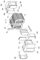
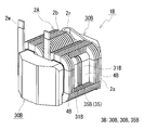
- FIG. FIG. 3 is an exploded perspective view illustrating a manufacturing process of the reactor according to the first embodiment. It is a schematic perspective view which shows the reactor of Embodiment 2. It is a disassembled perspective view explaining the manufacturing process of the reactor of Embodiment 2. FIG. It is a schematic perspective view which shows the reactor of Embodiment 3. It is a disassembled perspective view explaining the manufacturing process of the reactor of Embodiment 3. FIG. It is a schematic perspective view which shows the reactor of Embodiment 4. It is a disassembled perspective view explaining the manufacturing process of the reactor of Embodiment 4.
- a reactor according to an aspect of the present invention includes a coil, a plurality of core pieces, and a gap material interposed between at least one set of core pieces, and forms a closed magnetic circuit with excitation of the coil.
- At least one gap material is a foamed resin gap material including a foamed resin portion made of foamed resin in a contact region with the core piece.
- the above-described reactor can suppress the occurrence of damage such as cracks in the vicinity of the connecting portion of the core pieces in the core pieces due to the stress that can be applied due to vibration during use for the following reasons. Moreover, said reactor is excellent also in manufacturability for the following reasons.
- the reactor includes a foamed resin gap material including a foamed resin portion between at least one set of core pieces.
- the foamed resin portion is a state in which the foamed resin is expanded in volume including bubbles.
- a gas is generally less likely to transmit vibration than a solid.
- the presence of bubbles between the core pieces can reduce the transmission of vibrations in the magnetic core (can absorb vibrations) as compared with the case where only solids are interposed between the core pieces.
- the stress resulting from the vibration etc. which can be provided to said reactor can be reduced and relieved.
- the stress applied to the vicinity of the connection location between the core pieces is reduced by the above-described vibration reduction and absorption. Can be relaxed.
- the foamed resin portion can be easily formed by using, for example, an unfoamed resin sheet.
- the unfoamed resin sheet is thinner than a predetermined interval provided between the core pieces.
- the resin sheet can be supported by sandwiching an unfoamed resin sheet between the core pieces until foaming is completed.
- a regulating member or the like may be arranged on the outer periphery of the magnetic core assembly so that the gap between the core pieces becomes a predetermined gap length after foaming.
- the regulating member simply needs to hold the core pieces at a predetermined interval and suppress separation of the core pieces due to foaming of the resin. Can be configured. Moreover, it is not necessary to arrange against the urging force of the elastic material, and the restricting member can be easily arranged. In particular, if a non-foamed resin sheet is used, it is possible to maintain the state of adhering to a core piece or a gap plate described later with the resin sheet itself.
- the coil and the core piece to which the unfoamed resin sheet is attached can be easily assembled, and the positional displacement of the resin sheet in the foaming process hardly occurs, and it is necessary to arrange a support member for the resin sheet. No workability. Even when the above-described regulating member is used, the regulating member can be easily arranged as described above, and the workability is excellent.
- the resin sheet is thin and the foamed resin part is thick.
- An unfoamed resin sheet is available that is very thin (for example, 200 ⁇ m or less). Even if it is thin, a predetermined gap length can be secured after foaming by using a sheet having a sufficiently large expansion coefficient.
- the core piece or a gap plate dimensional error described later even if there is a dimensional error of the core piece or a gap plate dimensional error described later, even if there is a dimensional error of the gap plate, it can be absorbed by the volume expansion of the foamed resin. Available. Thus, the material can be easily selected and the workability is excellent.
- At least one foamed resin gap material may have a form in which the whole is the above-mentioned foamed resin portion.
- the above embodiment includes a foamed resin gap material substantially composed of a foamed resin between at least one pair of core pieces. Since this foamed resin gap material contains more air bubbles and more air bubbles are present between the core pieces, the above-described configuration can further alleviate the stress described above. Moreover, since the said form can form a foamed resin gap material easily by making it foam according to the space
- a foamed resin gap material hereinafter sometimes referred to as a single-layer gap material
- At least one foamed resin gap material may include a form including a gap plate and the foamed resin portion provided on one or both surfaces of the gap plate.
- the above-described embodiment includes a foamed resin gap material constituted by a gap plate substantially free of bubbles and a foamed resin portion containing bubbles between at least one pair of core pieces.
- the above-described form can relieve the stress described above.
- the said form can use the gap board which can make the thickness of a foamed resin part thin, can shorten the foaming time of an unfoamed resin sheet, or is inferior to some extent in dimensional accuracy as mentioned above by providing a gap board. It is excellent in manufacturability.
- All the gap materials provided in the magnetic core can be foamed resin gap materials (hereinafter sometimes referred to as multilayer gap materials) including a gap plate and a foamed resin portion.
- multilayer gap materials foamed resin gap materials
- the magnetic core includes a plurality of gap materials
- the single-layer gap material described in (2) above and the multilayer gap material described in (3) above can be combined.
- the foamed resin gap material is present in the magnetic core in the above-described form, there are few steps for placing an unfoamed resin sheet between the core pieces in the manufacturing process, and there is a restriction on the spacing between the core pieces. Fewer parts are needed, the spacing between the core pieces can be accurately regulated, and it is superior in manufacturability. Depending on the shape of the core piece, a member for regulating the interval can be dispensed with, which is excellent in manufacturability.
- each core piece is a composite material including soft magnetic powder and resin.
- the core piece composed of the composite material may be inferior in strength as compared with the case where it is composed of a powder compact or an electromagnetic steel sheet as described above, the above form is a foamed resin including a foamed resin portion. Since the gap material is provided, the above stress can be relieved.
- the composite material contains a resin
- the gap length is short, the loss (copper loss) caused by the leakage magnetic flux can be reduced even if the coil and the portion of the magnetic core disposed in the winding portion are arranged close to each other.
- the surface resin layer can be used as an insulating layer between the coils. Therefore, the said form can make a coil and a magnetic core adjoin, and can be made small.
- a method for manufacturing a reactor according to one aspect of the present invention relates to a method for manufacturing a reactor by assembling a coil and a magnetic core including a plurality of core pieces.
- arrangement process The process of arrange
- Foaming process According to a predetermined gap length, the unfoamed resin sheet is foamed in a state where the interval between the core pieces where the unfoamed resin sheet is interposed is restricted, and the foamed resin is formed between the core pieces.
- the process of forming the foamed resin part comprised.
- the above reactor manufacturing method includes a reactor including a foamed resin portion between core pieces in a simple process of foaming the resin sheet in a state in which a space between core pieces in which an unfoamed resin sheet is interposed is regulated. Can be manufactured.
- the reactor can reduce or alleviate stress that can be applied to the magnetic core during use as described above.
- the unfoamed resin sheet interposed between the core pieces can be supported by a pair of core pieces themselves arranged to face each other, and even when a restriction member is used, foaming is performed as described above. It is only necessary to suppress the separation between the core pieces, and the regulating member can be easily arranged.
- a non-foamed resin sheet that has such a degree of adhesive that it can maintain the state of adhering to the core piece, and in the case where a gap plate is used, the adhesive that can maintain the state of the resin sheet adhering to the gap plate. If it has a property, the assembly of a coil and the core piece which adhered the said resin sheet can also be performed easily. Further, the restriction member and the arrangement process thereof may be omitted.
- the manufacturing method of said reactor can manufacture easily the reactor which can reduce and relieve
- a reactor 1A according to the first embodiment will be described with reference to FIGS. (Reactor) Overall Configuration
- the reactor 1A is interposed between a coil 2A including a pair of winding portions 2a and 2b formed by spirally winding the winding 2w, and a plurality of core pieces 30A and 30A and the core pieces 30A and 30A.
- Reactor 1A is typically used by being attached to an installation target such as a converter case using a fixing member (not shown) such as a bolt.
- Reactor 1A is characterized in that at least one gap material among the plurality of gap materials is a foamed resin gap material 35A including a foamed resin portion 35 composed of a foamed resin portion.
- a foamed resin gap material 35A in this example includes one gap plate 355 and foamed resin portions 35 and 35 provided on both surfaces of the gap plate 355, respectively.
- the constituent material of each of the core pieces 30A and 30A is a composite material including soft magnetic powder and resin.
- the coil 2A of this example includes a pair of cylindrical winding portions 2a and 2b formed by spirally winding a single continuous winding 2w, and a winding 2w. And a connecting portion 2r for connecting both winding portions 2a and 2b.
- the winding parts 2a, 2b are arranged in parallel (side by side) so that their axes are parallel to each other.
- the winding 2w in this example is a covered rectangular wire (so-called enameled wire) having a flat wire conductor (copper or the like) and an insulating coating (polyamideimide or the like) on the outer periphery of the conductor, and the winding portions 2a and 2b are It is an edgewise coil.
- the winding parts 2a and 2b in this example are in the shape of a square cylinder with rounded corners, and each inner peripheral surface has four planes and four curved surfaces (surfaces forming corners) connecting adjacent planes. ) And.
- Both ends of the winding 2w are pulled out from the winding portions 2a and 2b in appropriate directions, and terminal fittings (not shown) or the like are attached to be electrically connected to an external device (not shown) such as a power source. Connected to.
- the magnetic core 3A includes a pair of U-shaped core pieces 30A and 30A as shown in FIG.
- Each of the core pieces 30A and 30A has the same shape, and a short columnar portion (hereinafter referred to as an inner core protrusion 31A) inserted and disposed in the winding portions 2a and 2b, and the coil 2A are substantially disposed.
- a columnar outer core portion 32A arranged so as to protrude from the coil 2A.
- the core piece 30A is a solid body in which a pair of inner core protrusions 31A and 31A protrude from the inner end surface 32e of the outer core part 32A.
- the inner core protrusion 31A has a rectangular parallelepiped shape with rounded corners, and the outer core portion 32A has a prismatic shape with trapezoidal upper and lower surfaces.
- the magnetic core 3A is assembled in an annular shape with the end faces 31e, 31e of the inner core protrusions 31A, 31A of both core pieces 30A, 30A facing each other.
- a gap corresponding to the gap length is provided between the end surface 31e of the inner core protrusion 31A of one core piece 30A and the end surface 31e of the inner core protrusion 31A of the other core piece 30A in a state of being annularly assembled. This gap is an arrangement place of one gap material.
- the magnetic core 3A has two gaps and a total of two gap members.
- the core piece 30A in this example is made of a composite material containing soft magnetic powder and resin. This composite material is molded using injection molding, cast molding, or the like. When injection molding is used, even a complicated three-dimensional shape such as having a concave portion 31r partially as described later can be easily molded.
- a powder of a soft magnetic material such as a metal such as iron or an iron alloy (Fe—Si alloy, Fe—Ni alloy, etc.) or a nonmetal such as ferrite can be suitably used.
- a thermosetting resin such as an epoxy resin or a thermoplastic resin such as a polyphenylene sulfide (PPS) resin can be used.
- the content of the soft magnetic powder in the composite material is 20 vol% or more and 80 vol% or less, and further 30 vol% or more and 70 vol% or less when the composite material is 100 vol%.
- the remainder is mainly a non-metallic organic material such as the above resin.
- the balance can further include non-metallic inorganic materials such as ceramics such as alumina and silica in addition to the resin (for example, 0.2% by volume to 20% by volume with 100% by volume of the composite material).
- the composite material can easily adjust the magnetic properties by adjusting the blending amount of soft magnetic powder, resin, non-metallic inorganic material and the like.
- a nonmagnetic material such as a resin
- the composite material can easily be obtained with a low relative magnetic permeability.
- the gap length can be easily shortened, and the leakage magnetic flux in the gap portion can be reduced.
- magnetic saturation is difficult.
- a of core pieces comprised from a composite material can be provided with the surface resin layer (it may contain the above-mentioned ceramics) substantially formed with resin in a composite material.
- the shape of the core piece 30A can be selected as appropriate. In addition to the U-shape shown in this example, it may be an E-shape as in Embodiments 3 and 4 to be described later.
- the lower surface of the outer core portion 32A protrudes from the lower surface of the inner core protrusion portion 31A, and is substantially flush with the lower surfaces of the winding portions 2a and 2b of the coil 2A. Therefore, the installation surface of reactor 1A is mainly composed of the lower surfaces of outer core portions 32A and 32A of both core pieces 30A and 30A and the lower surfaces of winding portions 2a and 2b. Since the installation surface of the reactor 1A is formed by both the coil 2A and the magnetic core 3A, the installation area is sufficiently large and excellent in stability. When the installation target includes a cooling mechanism, the installation surface of the reactor 1A functions as a heat dissipation surface, and the reactor 1A is excellent in heat dissipation.
- the gap material has a thickness set according to a predetermined gap length. In the case of using a plurality of gap materials, the thickness of each gap material may be a length obtained by equally dividing the total gap length. In this example, the thickness of each gap material is made equal.
- Each gap material is a foamed resin gap material 35A.
- the foamed resin gap material 35A includes a foamed resin portion 35 in a contact region with the core piece 30A, and includes a gap plate 355 at an intermediate position in the thickness direction.
- Each foamed resin gap material 35A in this example has the same configuration and the same size.
- the specific configuration is that one gap plate 355 interposed between the end surfaces 31e, 31e of the inner core protrusions 31A, 31A of the pair of core pieces 30A, 30A, one surface of the gap plate 355, and one core piece 30A.
- Foamed resin portion 35 interposed between the end surface 31e of the inner core protrusion 31A, and foaming interposed between the other surface of the gap plate 355 and the end surface 31e of the inner core protrusion 31A of the other core piece 30A.
- a three-layer multilayer gap material including a resin portion 35.
- the foamed resin portion 35 and the core piece 30 ⁇ / b> A, and the foamed resin portion 35 and the gap plate 355 are in close contact with each other due to the volume expansion of the foamed resin portion 35.
- the foamed resin portion 35 has adhesiveness, and the foamed resin portion 35 and the core piece 30A and the gap plate 355 are in close contact with each other by the adhesive force of the foamed resin portion 35 itself.
- the magnetic core 3A is maintained in an annular state. Therefore, the foamed resin portion 35 also functions as an adhesive for integrating the magnetic core 3A, and no additional adhesive for joining the core pieces 30A and 30A is necessary (this point is also described in Embodiment 3 described later). The same).
- the gap plate 355 is a member that suppresses magnetic saturation of the magnetic core 3A, and has a lower relative permeability than the core piece 30A.
- Examples of the gap plate 355 include those composed substantially only of a nonmagnetic material and those composed of a mixture containing a nonmagnetic material and a soft magnetic material.
- Nonmagnetic materials include nonmetallic inorganic materials such as alumina, and nonmetallic organic materials typified by resins such as unsaturated polyesters and PPS resins.
- the mixture include those containing PPS resin and soft magnetic powder such as iron powder.
- the gap plate 355 containing resin is preferably excellent in heat resistance to withstand the temperature during the heat treatment for forming the foamed resin portion 35.
- the shape and size of the gap plate 355 can be selected as appropriate. Typically, as shown in FIG. 2, it has substantially the same shape as the end surface 31e of the inner core protrusion 31A of the core piece 30A, and has a size equivalent to or smaller than the area of the end surface 31e. It is done. In this case, the peripheral edge of the gap plate 355 does not protrude from the outer periphery of the inner core protrusion 31A, and a small magnetic core 3A can be obtained.
- the foamed resin portion 35 is composed of a plurality of bubbles and a resin that encloses these bubbles. Since this resin is disposed close to the coil 2A, it is preferable that the resin has excellent electrical insulation and heat resistance with respect to the maximum temperature reached by the coil 2A (for example, 150 ° C. or higher, more preferably 180 ° C. or higher).
- the resin preferably has excellent resistance to the liquid refrigerant. Specific examples of the resin include PPS, nylon, and epoxy resin.
- the foamed resin portion 35 can be easily formed by using, for example, an unfoamed resin sheet 350 (FIG. 2, details will be described later) cut into a predetermined shape and size.
- the foamed resin portion 35 is formed by foaming a resin sheet 350 having a predetermined shape sandwiched between the core pieces 30A and 30A. Therefore, the shape of the foamed resin portion 35 is substantially similar to the shapes of the end surface 31e of the inner core protrusion 31A of the core piece 30A and the gap plate 355, and is flat.
- the ratio of the thickness of the foamed resin portion 35 to the thickness of one foamed resin gap material 35A (hereinafter referred to as the thickness ratio) can be selected as appropriate. Since the foamed resin gap material 35B shown in the second embodiment to be described later can be substantially composed only of the foamed resin, the upper limit of the thickness ratio is 100%. It is expected that the greater the thickness ratio, the greater the distribution of the foamed resin portion 35, and the smaller the distribution of the gap plate 355, the more bubbles exist between the core pieces 30A and 30A, and the better the stress relaxation properties. On the other hand, the smaller the thickness ratio and the greater the distribution of the gap plate 355, the shorter the foaming time for forming the foamed resin portion 35 and the better the productivity.
- the thickness ratio is, for example, 10% or more and 90% or less, and further 30% or more and 70% or less. In this example, it is about 67% (this is the same in Embodiment 3 described later).
- the non-foamed resin sheet 350 is thinner than the foamed resin portion 35 after foaming, and is excellent in workability because it is excellent in flexibility and can be easily disposed at any shape.
- the manufacturing method of the reactor of Embodiment 1 utilizes the unfoamed resin sheet 350.
- the unfoamed resin sheet 350 is made of a resin containing capsule particles filled with a liquid, and the liquid is vaporized by heating and the capsule expands to expand the resin.
- the unfoamed resin sheet 350 is in a semi-solidified state, a semi-cured state, or the like and has a certain degree of adhesiveness, the resin sheet 350 is formed on the end surface 31e of the inner core protrusion 31A or the gap plate 355 of the core piece 30A. It is preferable because it is easy to maintain the state of adhering.
- the laminate falls off from the core piece 30A or the gap from the laminate. It is possible to prevent the plate 355 from being peeled off, and it is excellent in assembling workability and manufacturing efficiency.
- an unfoamed resin sheet 350 containing an adhesive component or having an adhesive layer is used, the core piece 30A and the gap plate 355 are strongly bonded to each other by the adhesive force of the foamed resin portion 35 after foaming. Can be joined.
- a release paper may be attached to the adhesive layer, and the release paper may be removed when the resin sheet 350 is disposed on the core piece 30A or the gap plate 355.
- the thickness before expansion in the unfoamed resin sheet 350 and the expansion rate are determined so that the total thickness of the foamed resin portions 35 and 35 after foaming is determined from the predetermined gap length provided between the core pieces 30A and 30A.
- the volume expansion amount satisfying the thickness obtained by reducing the thickness of 355 can be selected within a range in which the volume expansion amount can be secured.
- the expansion coefficient is obtained by (thickness of the foamed resin part after foaming / thickness of the unfoamed resin sheet before foaming). When the volume expansion amount may be small to some extent, for example, when the gap plate 355 is included in the foamed resin gap material 35A as in this example or Embodiment 3 described later, the expansion coefficient is 1.5 or more and 2 or less. Can be about.
- the foaming time can be shortened and the productivity is excellent.
- the expansion coefficient is, for example, about 2 or more and 5 or less, further 3 or more, 4 or more, 4.5 or more.
- the thickness of the unfoamed resin sheet 350 0.2 mm or more is mentioned, for example.
- the unfoamed resin sheet 350 may be adjusted so that the foamed resin portion 35 after foaming has a predetermined shape and size.
- the size of the end surface 31e of the inner core protrusion 31A and the size of one surface of the gap plate 355 in the core piece 30A that forms the existence space of the foamed resin portion 35 is the same as or slightly smaller than the size, It is easy to suppress the amount of leakage from the outer periphery of the core piece 30A after foaming.
- the foamed resin leaked to the outer periphery of the core piece 30A can also be used for joining with the core piece 30A.
- the unfoamed resin sheet 350 and the gap plate 355 have the same shape and the same size, and the shape corresponding to the end surface 31e of the rectangular parallelepiped inner core protrusion 31A with rounded corners included in the core piece 30A ( An example of a rectangular shape with rounded corners) is shown.
- the manufacturing method of the reactor of Embodiment 1 has assembled the coil 2A and a pair of core pieces 30A and 30A, and arrange
- the coil 2A, U-shaped core pieces 30A and 30A, a plurality of unfoamed resin sheets 350, and a gap plate 355 are prepared. Then, two laminates having a three-layer structure in which each surface of the gap plate 355 is sandwiched between unfoamed resin sheets 350 and 350 are prepared.
- the inner core protrusions 31A and 31A provided in one core piece 30A are inserted from one opening in each winding part 2a and 2b of the coil 2A.
- the end face 31e, 31e of the inner core projecting part 31A, 31A is inserted into the other core piece 30A while the end face 31e, 31e is stopped.
- the inner core protrusions 31A and 31A provided are inserted.
- the resin sheet 350 When the unfoamed resin sheet 350 has adhesiveness, the resin sheet 350 is attached to the end surfaces 31e and 31e of the inner core protrusions 31A and 31A provided in the one core piece 30A, respectively.
- One core piece 30A on which 350 is disposed, the coil 2A, and the other core piece 30A are assembled.
- the resin sheets 350 and 350 of the laminate having the three-layer structure can be attached to the end faces 31e and 31e of the inner core protrusions 31A and 31A that are opposed to each other in both the core pieces 30A and 30A.
- the state in which the laminate is interposed between the end faces 31e and 31e can be more reliably maintained by the adhesiveness of the resin sheets 350 and 350 itself.
- the interval is regulated according to the predetermined gap length so that the predetermined interval can maintain the predetermined gap length.
- the outer end surfaces of the outer core portions 32A and 32A of the core pieces 30A and 30A may be sandwiched between restriction members (not shown). In this regulated state, heat treatment for foaming is performed to foam the resin sheet 350 to form the foamed resin portion 35 made of foamed resin.
- the heating temperature and holding time of the heat treatment may be appropriately selected according to the type of resin so as to have a predetermined gap length.
- the heating temperature is about 100 ° C. or higher and 170 ° C. or lower.
- Use of a resin (sheet) having a low heating temperature and a short holding time is preferable because thermal damage to the coil 2A and the magnetic core 3A (particularly the resin component) can be prevented during heat treatment.
- a resin (sheet) that can be foamed at a low temperature in a short time the productivity can be improved and the cost can be reduced.
- the foamed resin portions 35 and 35 can be formed on both sides of the gap plate 355, respectively.
- the foamed resin is interposed between the end surfaces 31e and 31e of the inner core protrusions 31A and 31A that are arranged to face each other, and is in close contact with both the end surface 31e of the inner core protrusion 31A and the gap plate 355.
- the unfoamed resin sheet 350 has an adhesive component or an adhesive layer, it adheres firmly to both the end surface 31e of the inner core protrusion 31A and the gap plate 355 by the adhesive strength and adhesive layer of the adhesive. it can.
- the reactor 1A provided with the foamed resin gap material 35A (multilayer gap material) including the gap plate 355 and the foamed resin portion 35 between the inner core protrusions 31A, 31A of the adjacent core pieces 30A, 30A. Can be manufactured.
- the reactor 1A since at least one of the gap materials is the foamed resin gap material 35A including the foamed resin portion 35 containing bubbles, stress caused by vibration or the like that can be imparted to the reactor 1A during use is foamed. Reduction and relaxation can be achieved by the resin gap material 35A. Therefore, the reactor 1A can suppress the occurrence of damage such as cracking in the vicinity of the connection location between the core pieces 30A and 30A due to this stress.
- the magnetic core 3A even when a location other than the connection location between the core pieces 30A and 30A, for example, the outer core portion 32A is an attachment location to the installation target, damage near the connection location between the core pieces 30A and 30A. Can be effectively suppressed.
- the reactor 1A can be easily manufactured by using a laminate including the unfoamed resin sheet 350 and the gap plate 355, and has excellent manufacturability.
- the unfoamed resin sheet 350 has adhesiveness, the state where the core piece 30A and the resin sheet 350 are in contact and the state where the gap plate 355 and the resin sheet 350 are in contact can be maintained by the resin sheet 350 itself.
- the coil 2A and the magnetic core 3A can be easily assembled, and a supporting jig for the resin sheet 350 is not required even during foaming, which is superior in manufacturability.
- the dimensional error of the core piece 30A and the gap plate 355 can be absorbed by the volume expansion of the foamed resin, and it is not necessary to adjust these dimensions with high accuracy, and the adjustment time can be shortened or eliminated, so that the productivity is excellent.
- the foamed resin portion 35 functions as an adhesive that joins the core pieces 30A and 30A, an adhesive for integrating the magnetic core 3A is not required. Excellent.
- the reactor 1A in this example is further excellent in manufacturability and is small for the following reasons because both the core pieces 30A and 30A are made of a composite material. Moreover, the reactor 1A of this example is excellent in manufacturability for the following reasons even when it includes a coil fixing portion 4A described later.
- the resin covering material of the core piece 30A such as the outer resin portion, the insulating interposition member called an insulator or bobbin interposed between the winding portions 2a, 2b of the coil 2A and the inner core protrusion 31A, etc. can be omitted. 1.
- the process and the arrangement process of the insulating interposed member can be omitted. 2. Even when the gap length is shortened, it is not necessary to adjust the thickness of the gap plate 355 with high accuracy.
- a foaming process for forming the foamed resin portion 35 and a foaming process for the coil fixing portion 4A described later can be performed simultaneously (small size).
- the surface resin layer mainly composed of resin in the composite material can be used as an insulating layer between the winding portions 2a and 2b.
- the winding portions 2a and 2b and the inner core protrusion 31A can be disposed close to each other.
- the reactor 1A of this example is further provided in the inner peripheral surfaces of the winding portions 2a and 2b of the coil 2A and the portions (here, the inner core protrusions) disposed in the winding portions 2a and 2b of the magnetic core 3A.
- 31A) is provided with a coil fixing portion 4A made of foamed resin in a cylindrical inner peripheral space between the outer peripheral surface and the outer peripheral surface.
- the coil fixing portion 4A regulates movements such as radial deformation, axial expansion and contraction, and circumferential rotation of the coil 2A by volume expansion of the foamed resin, and the coil with respect to the magnetic core 3A caused by such movement of the coil 2A 2A misalignment can be prevented.
- the non-foamed resin sheet 40A described above can be used to form the coil fixing portion 4A.
- the resin sheet 40A may be disposed at a predetermined position on the outer peripheral surface of the inner core protrusion 31A and assembled with the coil 2A, and then heat treatment for foaming may be performed. This heat treatment can be performed simultaneously with the heat treatment for forming the above-described foamed resin gap material 35A. Therefore, the form provided with the coil fixing part 4A can be manufactured by adding the arrangement step of the resin sheet 40A, and is excellent in manufacturability.
- the resin sheet 40A has adhesiveness, it is excellent in assembling workability with the coil 2A.
- the coil fixing portion 4A can be in close contact with the coil 2A and the magnetic core 3A after foaming.
- a part of the foamed resin can enter between adjacent turns provided in the winding portions 2a and 2b of the coil 2A.
- the foamed resin that has entered between the turns also constitutes a part of the coil fixing portion 4A.
- a recess 31r as shown in FIG. 2 at a predetermined position on the outer peripheral surface of the inner core protrusion 31A because the unfoamed resin sheet 40A can be easily positioned.
- the shape and size of the recess 31r may be selected according to the shape and size of the resin sheet 40A. In particular, when the recess 31r is provided extremely shallow in the vicinity of the outer peripheral surface of the inner core protrusion 31A as shown in FIG. 2, it is possible to suppress a decrease in the magnetic path area due to the formation of the recess 31r.
- the thickness of the resin sheet 40A is equal to or greater than the thickness of the resin sheet 40A, it is difficult for the resin sheet 40A to fall off the recess 31r during assembly with the coil 2 or the inner surface of the winding portions 2a and 2b of the coil 2 is contacted. It is preferable because it is difficult to be displaced. From these points, it is considered that the depth of the recess 31r is preferably about equal to or greater than 1.3 times the thickness of the resin sheet 40A.
- the above-described range of the coil fixing portion 4A in the inner circumferential space is an example, and can be changed as appropriate.
- the form including one coil fixing part 4A continuous in the circumferential direction in the inner circumferential space as in this example, the form including a plurality of coil fixing parts intermittently in the circumferential direction in the inner circumferential space; can do.
- the coil fixing portion can be formed only at a location that hardly affects the magnetic path (in this example, a corner portion or the like).
- the coil fixing portion 4A is formed in a [shape or] shape over a total of three flat portions of the upper and lower flat portions and the outer flat portion in the inner circumferential space described above and two corner portions connecting them. Exists.
- the surfaces other than the adjacent inner surface, in this case, the upper and lower surfaces and the outer surface, and these three surfaces The resin sheet 40A may be disposed so as to cover the two corners connecting the two. Even when the interval between the adjacent inner core protrusions 31A and 31A is narrow, the resin sheet 40A can be easily arranged, and the productivity is excellent.
- the resin sheet 40A is further provided. Easy to place.
- one coil fixing portion 4B, 4C continuous in the circumferential direction is provided in a space between the inner peripheral surface of the coil and the facing surface of the magnetic core. It is a form (FIG. 3, FIG. 5), Embodiment 4 mentioned later shows a form provided with several coil fixing
- the reactor 1B of Embodiment 2 is demonstrated with reference to FIG. 3, FIG.
- the basic configuration of the reactor 1B of the second embodiment is the same as that of the reactor 1A of the first embodiment, and includes a coil 2A including a pair of winding portions 2a and 2b, two U-shaped core pieces 30B and 30B, A magnetic core 3B including two gap members interposed between the core pieces 30B and 30B.
- Each gap material is a foamed resin gap material 35 ⁇ / b> B including the foamed resin portion 35.
- the entire foamed resin gap material 35B is the foamed resin portion 35 and does not include the gap plate 355 (FIG. 2).
- this difference will be described in detail, and a detailed description of overlapping configurations and effects will be omitted.
- Each foamed resin gap material 35B in this example has the same configuration and the same size, and is a single-layer gap material made entirely of foamed resin.
- the foamed resin gap material 35B is interposed between the end surface 31e of the inner core protrusion 31B provided in the one core piece 30B opposed to the end surface 31e of the inner core protrusion 31B provided in the other core piece 30B. And has a thickness corresponding to a predetermined gap length.
- the foamed resin gap material 35B is in close contact with both end faces 31e and 31e due to the volume expansion of the foamed resin.
- the foamed resin portion 35 further has adhesiveness, and is in close contact with the core piece 30B by the adhesive force of the foamed resin portion 35 itself. Therefore, as in the first embodiment, the foamed resin portion 35 also functions as an adhesive for integrating the magnetic core 3B, and no additional adhesive is required to join the core pieces 30B and 30B (this point). The same applies to Embodiment 4 described later).
- Each foamed resin gap material 35B (foamed resin portion 35) can be easily formed by using an unfoamed resin sheet 352 as in the first embodiment.
- the resin sheet 352 may have a coefficient of expansion that is such that the thickness after foaming is equal to or greater than a predetermined interval between the end faces 31e and 31e of the inner core protrusions 31B and 31B.
- it is arranged between the end faces 31e, 31e of the inner core protrusions 31B, 31B that are abutted with the unfoamed resin sheet 352 instead of the laminate of the above three-layer structure,
- the subsequent steps may be the same as in the first embodiment (FIG. 4).
- the reactor 1B of the second embodiment since at least one of the gap materials is a foamed resin gap material 35B composed of a foamed resin containing bubbles, stress caused by vibration or the like that can be imparted to the reactor 1B during use is foamed. It can be relieved by the resin gap material 35B. And the reactor 1B can be easily manufactured by disposing an unfoamed resin sheet 352 between the core pieces 30B and 30B and foaming in a state where the interval between the core pieces 30B and 30B is regulated according to the gap length. Also excellent in manufacturability. When the unfoamed resin sheet 352 has adhesiveness, it is excellent in manufacturability because it is excellent in assembling workability and workability during foaming. In particular, since the reactor 1B of the second embodiment does not include the gap plate 355, the number of parts to be assembled in the manufacturing process of the foamed resin gap material 35B is small, and the productivity is excellent.
- the reactor 1B of this example includes one outer corner in the inner space between the winding portions 2a and 2b of the coil 2A and the inner core protrusion 31B and two flat portions sandwiching the corner.
- An example in which a ⁇ -shaped or hook-shaped coil fixing portion 4B exists is shown.
- the coil fixing portion 4B is formed on the outer peripheral surface of one inner core protrusion 31B (here, the upper surface, the upper corner, and the outer surface connected to the corner), with one recess 31r.
- the resin sheet 40B can be easily arranged (FIG. 4).
- the lower (installation side) flat portion in the inner peripheral space and the space in the vicinity thereof can be used as the above-described space for improving heat dissipation.
- the reactor 1C of the third embodiment is common to the reactor 1A of the first embodiment in that a coil, a plurality of core pieces, and a foamed resin gap material including a foamed resin portion are included, and the shape of the coil, the shape of the magnetic core, The number of gap materials is different.
- the reactor 1C includes a coil 2C having one winding part 2c, two E-shaped core pieces 30C and 30C made of a composite material, and one interposed between the core pieces 30C and 30C.
- the differences will be described in detail, and detailed description of overlapping configurations and effects will be omitted.
- the coil 2C includes a cylindrical winding portion 2c formed by spirally winding a single continuous winding 2w, as shown in FIG. Has been pulled out in the direction.
- the winding part 2c of this example is an edgewise coil using the covered rectangular wire described in the first embodiment, and has a shape obtained by rounding the inner and outer corners of the square tube.
- Magnetic core 3C provided in the reactor 1C includes two core pieces 30C and 30C as shown in FIG. 6, and a part between the core pieces 30C and 30C (inner core protrusions 31C and 31C described later in detail). A gap).
- Each of the core pieces 30C and 30C has the same shape, which is similar to a so-called EE type core.
- the core piece 30C includes a short columnar inner core protrusion 31C that is inserted and arranged in the winding portion 2c, and an outer core portion 32C in which the coil 2C is not substantially arranged.
- the outer core portion 32C is connected to the inner core protruding portion 31C, is connected to the plate-like connecting portion 32o facing the end surface of the coil 2C, and the connecting portion 32o so as to cover a part of the outer peripheral surface of the coil 2C.
- a pair of outer peripheral portions 32s and 32s are provided.
- the inner core protrusion 31C protrudes from the central portion of the inner end surface 32e of the connecting portion 32o, and the outer peripheral portions 32s and 32s respectively extend from the portions near both edges of the inner end surface 32e to the inner core protrusion 31C. It is a solid projecting in parallel.
- the end surfaces of the outer peripheral portions 32s and 32s protrude beyond the end surface 31e of the inner core protrusion 31C. Therefore, in a state where the pair of core pieces 30C, 30C are assembled so that the end faces of the outer peripheral portions 32s, 32s of both core pieces 30C, 30C are in contact with each other, the end face 31e of the inner core protrusion 31C of one core piece 30C A gap of a predetermined size is provided between the end face 31e of the inner core protrusion 31C of the other core piece 30C.
- the magnetic core 3C uses this gap as a magnetic gap, and a foamed resin gap material 35C is provided in this gap.
- the inner core protrusion 31C in this example has a rectangular parallelepiped shape with rounded corners, and the connecting portion 32o and the outer peripheral portion 32s have a flat plate shape.
- the magnetic core 3C forms an annular closed magnetic circuit by assembling the end faces 31e, 31e of the inner core protrusions 31C, 31C of both core pieces 30C, 30C and the end faces of the outer peripheral part 32s so as to face each other.
- This closed magnetic path is formed by the inner core protrusion 31C of one core piece 30C ⁇ the foamed resin gap material 35C ⁇ the inner core protrusion 31C of the other core piece 30C ⁇ the connecting portion 32o of the other core piece 30C ⁇ the other core piece 30C.
- the outer peripheral portion 32s ⁇ the outer peripheral portion 32s of the one core piece 30C ⁇ the loop of the connecting portion 32o of the one core piece 30C is formed.
- the winding portion 2c is disposed in a gap between the inner core protrusion 31C formed by assembling both the core pieces 30C and 30C and the outer peripheral portions 32s and 32s.
- the end face of the winding part 2c is in contact with or faces the inner end face 32e of the connecting part 32o.
- the installation surface of reactor 1C is mainly configured by the lower surface of outer core portion 32C and the lower surface of winding portion 2c.
- the foamed resin gap material 35C is a multilayer gap material including the gap plate 355 and the foamed resin portions 35 and 35 provided on both surfaces of the gap plate 355, similarly to the foamed resin gap material 35A of the first embodiment.
- the thickness of the foamed resin gap material 35C is set according to a predetermined gap length, and corresponds to the interval between the end faces 31e, 31e of the inner core protrusions 31C, 31C provided in both the core pieces 30C, 30C. .
- the shape and size (area) of the foamed resin portion 35 and the gap plate 355 constituting the foamed resin gap material 35C are the same as those of the first embodiment in the shape of the end surface 31e of the inner core protruding portion 31C (rectangular shape with rounded corners). Shape) and size (area), and the foamed resin portion 35 has a flat plate shape.
- Such a foamed resin gap material 35 ⁇ / b> C can be similarly formed by using an unfoamed resin sheet 350 (FIG. 6) and a gap plate 355, as in the first embodiment.
- the reactor 1C of the third embodiment can be manufactured basically in the same manner as the reactor 1A of the first embodiment.
- a coil 2C, a pair of core pieces 30C and 30C, and a laminate having a three-layer structure in which each surface of the gap plate 355 is sandwiched between unfoamed resin sheets 350 and 350 are prepared.
- FIG. 6 The coil 2C and the pair of core pieces 30C and 30C are assembled, and a laminate including the unfoamed resin sheet 350 is disposed between the adjacent core pieces 30C.
- a gap of a predetermined size is automatically provided between the end surfaces 31e and 31e of the inner core protrusions 31C and 31C.
- the state in which the laminate is interposed between the end faces 31e and 31e can be maintained.
- the resin sheet 350 has adhesiveness, it can maintain the above-mentioned interposition state more favorably by adhering to the end surface 31e.
- the expansion rate is appropriately controlled by adjusting the temperature or the like, so that the gap between the core pieces 30C described in the first embodiment is controlled.
- a regulating member that regulates the interval can be omitted. For example, when the expansion coefficient is increased, a regulating member can be used.
- Both the core pieces 30C and 30C are assembled, and the foamed resin portion 35 is formed by foaming the unfoamed resin sheet 350 in a state where the above-described interval is regulated. By doing so, a reactor 1C including the foamed resin gap material 35C (multilayer gap material) is obtained.
- the foamed resin gap material 35C is in close contact with both end faces 31e and 31e of the inner core protrusions 31C and 31C provided in both the core pieces 30C and 30C by the volume expansion of the foamed resin.
- the foamed resin portion 35 further has adhesiveness, and is in close contact with the core piece 30C by the adhesive force of the foamed resin portion 35 itself.
- the reactor 1C of the third embodiment is a foamed resin gap material 35C provided with a foamed resin portion 35 in which the gap material includes air bubbles, stress caused by vibration or the like that can be imparted to the reactor 1C at the time of use is applied to the foamed resin gap material 35C. Can be relaxed by.
- the reactor 1C can be easily manufactured by foaming a laminate of the unfoamed resin sheet 350 and the gap plate 355 interposed between the core pieces 30C and 30C, and is excellent in manufacturability.
- the unfoamed resin sheet 350 has adhesiveness, it is excellent in manufacturability because it is excellent in assembling workability and workability during foaming.
- the reactor 1C of the third embodiment is excellent in manufacturability because the regulating member that regulates the interval between the core pieces 30C and 30C at the time of foaming can be omitted.
- the reactor 1C since the reactor 1C has only one foamed resin gap material 35C, ( ⁇ ) there are few assembly parts used in the manufacturing process, and ( ⁇ ) the interval between the core pieces 30C and 30C is determined according to the gap length. It is excellent in manufacturability from the point of being well regulated.
- the reactor 1C of this example connects these three flat portions, that is, the upper flat portion and the left and right flat portions in the inner circumferential space between the winding portion 2c of the coil 2C and the inner core protrusion 31C.
- An example in which a ⁇ -shaped coil fixing portion 4C exists between two upper corners is shown.
- Each core piece 30C is provided with one recess 31r at the location where the coil fixing portion 4C is formed on the outer peripheral surface of the inner core protrusion 31C (here, the region extending from the upper surface, the upper two corners, and the left and right surfaces).
- the resin sheet 40C can be easily arranged.
- the lower (installation side) flat portion in the inner peripheral space and the space in the vicinity thereof can be used as the above-described space for improving heat dissipation.
- a reactor 1D according to the fourth embodiment will be described with reference to FIGS.
- the basic configuration of the reactor 1D according to the fourth embodiment is the same as that of the reactor 1C according to the third embodiment.
- the coil 2C includes one winding part 2c, two E-shaped core pieces 30D and 30D, and the core piece. 30D, and a magnetic core 3D provided with one gap material interposed between 30D.
- the gap material is a foamed resin gap material 35 ⁇ / b> D including the foamed resin portion 35.
- one of the differences from the third embodiment is that the entire foamed resin gap material 35D is the foamed resin portion 35 and does not include the gap plate 355 (FIG. 6).
- the reactor 1 ⁇ / b> D is common to the third embodiment in that only one foamed resin gap material 35 ⁇ / b> D is provided.
- the differences will be described in detail, and detailed description of overlapping configurations and effects will be omitted.
- the foamed resin gap material 35D is a single-layer gap material that is entirely made of foamed resin.
- the foamed resin gap material 35D is interposed between the end surface 31e of the inner core protrusion 31D provided in the one core piece 30D arranged to face the end surface 31e of the inner core protrusion 31D provided in the other core piece 30D. And has a thickness corresponding to a predetermined gap length.
- the foamed resin gap material 35D is in close contact with both end faces 31e and 31e due to the volume expansion of the foamed resin.
- the foamed resin portion 35 in this example has adhesiveness, and the foamed resin gap material 35D and the core piece 30D are in close contact also by the adhesive force of the foamed resin portion 35 itself.
- Such a foamed resin gap material 35D (foamed resin portion 35) can be easily formed by using an unfoamed resin sheet 352 having a predetermined expansion coefficient, as in the second embodiment.
- the gap material is a foamed resin gap material 35D composed of a foamed resin containing bubbles
- stress caused by vibration or the like that can be imparted to the reactor 1D during use is applied to the foamed resin gap material. Can be relaxed by 35D.
- the reactor 1D can be easily manufactured by disposing an unfoamed resin sheet 352 between the core pieces 30D and 30D and foaming in a state in which the interval between the core pieces 30D and 30D is regulated according to the gap length. Also excellent in manufacturability.
- the unfoamed resin sheet 352 has adhesiveness, it is excellent in manufacturability because it is excellent in assembling workability and workability during foaming.
- the reactor 1D of the fourth embodiment does not include the gap plate 355, as in the second embodiment, and therefore, the number of parts to be assembled in the manufacturing process of the foamed resin gap material 35D is small, as in the third embodiment. Since the spacing regulating member can be omitted and the number of the foamed resin gap material 35D is one, it is excellent in manufacturability from the viewpoint of easily regulating the spacing between the core pieces 30D and 30D with high accuracy.
- the reactor 1D of this example includes a ⁇ -shaped coil fixing portion 4D (FIG. 7) disposed vertically opposite to the inner circumferential space between the winding portion 2c of the coil 2C and the inner core protrusion 31D.
- fixed part 4D exists is shown.
- One of the ⁇ -shaped coil fixing portions 4D extends over a total of three flat portions of the upper flat portion and a part of the left and right flat portions in the inner peripheral space, and two upper corner portions connecting these portions. Is provided.
- the other U-shaped coil fixing portion 4D has a total of three flat portions of the lower flat portion and the other portions of the left and right flat portions in the inner peripheral space, and two lower corner portions connecting them. It is provided over.
- Two concave portions 31r are provided at the location where the coil fixing portion 4D is formed on the outer peripheral surface of one inner core protrusion 31D, and the unfoamed resin sheets 40D and 40D can be easily arranged.
- Embodiments 1 to 4 described above can be modified or added as follows.
- (A) Form in which the foamed resin portion 35 is disposed only on one surface of the gap plate 355 in the multilayer gap material described in the first and third embodiments (b) Form in which the multilayer gap material includes a plurality of gap plates 355 ( c) Form including both the multilayer gap material described in Embodiments 1 and 3 and the above and the single-layer gap material described in Embodiments 2 and 4 (d) Core composed of a green compact and an electromagnetic steel sheet Form including pieces (e) Form in which the magnetic core includes three or more core pieces (f) The magnetic core includes three or more gap members, and each gap member is a multilayer gap described in the first to fourth embodiments.
- Form which is a material or a single layer gap material
- a form provided with a resin mold part which covers the perimeter of a magnetic core, or a core piece, or a combination of a core piece and a gap material.
- the recess 31r can be provided in the resin mold part.
- the core piece is made of a composite material
- the mounting portion made of the composite material is integrally formed.
- the mounting portion is a fastening member such as a bolt for fixing the reactor to the installation target.
- (I) Form including a sensor for measuring a physical quantity of a reactor such as a temperature sensor, a current sensor, a voltage sensor, a magnetic flux sensor, etc.
- the outer peripheral surface of the coil is made of metal, ceramics, etc.
- Form with an excellent heat sink (k)
- Form with a bonding layer (preferably made of an insulating material such as an insulating adhesive) fixed on the installation surface of the reactor and the heat sink
- the reactor of the present invention includes various on-vehicle converters (typically DC-DC converters) mounted on vehicles such as hybrid vehicles, plug-in hybrid vehicles, electric vehicles, and fuel cell vehicles, and converters for air conditioners. It can utilize suitably for the component of a converter and a power converter.
- DC-DC converters typically DC-DC converters mounted on vehicles such as hybrid vehicles, plug-in hybrid vehicles, electric vehicles, and fuel cell vehicles, and converters for air conditioners. It can utilize suitably for the component of a converter and a power converter.
Landscapes
- Engineering & Computer Science (AREA)
- Power Engineering (AREA)
- Chemical & Material Sciences (AREA)
- Composite Materials (AREA)
- Manufacturing & Machinery (AREA)
- Insulating Of Coils (AREA)
- Coils Or Transformers For Communication (AREA)
Abstract
磁性コアに負荷され得る応力を低減、緩和でき、製造性にも優れるリアクトル、及びリアクトルの製造方法を提供する。コイルと、複数のコア片と、少なくとも一組のコア片間に介在されるギャップ材とを備え、前記コイルの励磁に伴い閉磁路を形成する磁性コアとを備え、少なくとも一つのギャップ材は、発泡樹脂から構成される発泡樹脂部を前記コア片との接触領域に含む発泡樹脂ギャップ材であるリアクトル。
Description
本発明は、ハイブリッド自動車などの車両に搭載される車載用DC-DCコンバータや電力変換装置の構成部品などに利用されるリアクトル、及びリアクトルの製造方法に関する。特に、磁性コアに負荷され得る応力を低減、緩和でき、製造性にも優れるリアクトルに関する。
電圧の昇圧動作や降圧動作を行う回路の部品の一つに、リアクトルがある。リアクトルは、巻線を螺旋状に巻回してなる筒状の巻回部を有するコイルと、巻回部の内外に配置されて、コイルの励磁に伴って閉磁路を形成する磁性コアとを備える。磁性コアには、軟磁性材料を主成分とする複数のコア片と、コア片間に介在され、アルミナなどの非磁性材料から構成されるギャップ板とを組み付けて形成されるものがある。コア片とギャップ板とは、例えば、特許文献1に記載されるようにエポキシ系接着剤やウレタン系接着剤(明細書の段落[0003])、常温硬化性の弾性接着剤(請求項1)を用いることで、一体化することができる。
特許文献2は、コア片間にシリコンゴムなどの弾性材料からなる弾性ギャップ材を介在すると共に、接着剤を用いずに一体化した磁性コアを開示している。特許文献2は、コイルと、磁性コアと、磁性コアを押し付ける板ばねとを組み付けてケースに収納し、これらを外側樹脂部で覆う構成、板ばねに代えて、磁性コアを帯状締付材で締め付けて環状に維持する構成を開示している。
磁性コアに負荷され得る応力を低減、緩和できて、製造性にも優れるリアクトルが望まれている。
上述のエポキシ系接着剤といった熱硬化性接着剤を用いた場合には、コア片同士が強固に固定される。その反面、後述するようにコア片におけるコア片同士の接続箇所近傍が機械的弱点となり得る。
使用時のリアクトルには、磁歪に起因する振動やリアクトルが取り付けられている自動車などが発する振動などが与えられる。磁性コアには、これらの振動などに起因する応力が付与される。コア片同士が強固に固定されていると、この応力によって、コア片と接着剤との界面が剥離するのではなく、コア片におけるコア片同士の接続箇所近傍で割れなどが生じ得る。即ち、コア片自体に損傷が生じる恐れがある。特に、コア片の構成材料が、磁性粉末と樹脂とを含む複合材料である場合には、コア片が圧粉成形体や電磁鋼板である場合に比較して、樹脂を多く含むために強度に劣る傾向にある。また、磁性コアのうち、コア片同士の接続箇所以外の箇所、代表的には巻回部から露出した部分を設置対象への取付箇所とする場合には、取付箇所から離れているコア片同士の接続箇所近傍は取付箇所を基点としてある程度動けることから、機械的強度の弱点と更になり易い。そのため、磁性コア、特にコア片に負荷される応力を低減、緩和できることが望まれる。
上述の常温硬化性の弾性接着剤や、ゴムといった弾性ギャップ材を用いた場合には、コア片間に介在される物質が固体であるため、気体よりも振動を伝達し易い。
更に、上述のように接着剤を用いず、ゴムといった弾性ギャップ材を用いた場合には、製造性に劣る。
詳しくは、コア片と弾性ギャップ材との組み付け状態を維持するために、外側樹脂部、更には板ばねや帯状締付材といった別部材が必要であり、外側樹脂部の形成工程、別部材の配置工程など工程数が多く、製造性の低下を招く。特に、板ばねの配置や帯状締付材の締付は、弾性ギャップ材による付勢力に抗して行うため、作業性に劣る。弾性接着剤を用いた場合には、弾性接着剤の固化工程で、所定のギャップ長になるように、弾性接着剤の付勢力に抗してコア片同士が近接するように磁性コアを締め付ける別部材が必要な場合も考えられる。この締付部材や上記の帯状締付材が弾性ギャップ材や弾性接着剤を締め付けすぎて、弾性ギャップ材などを押し潰さないように、締付量を調整可能な機構などを配置すると、更に作業性に劣る。
そこで、本発明の目的の一つは、磁性コアに負荷され得る応力を低減、緩和でき、製造性にも優れるリアクトルを提供することにある。
本発明の別の目的は、磁性コアに負荷され得る応力を低減、緩和できるリアクトルを容易に製造できるリアクトルの製造方法を提供することにある。
本発明の一態様に係るリアクトルは、コイルと、複数のコア片と、少なくとも一組のコア片間に介在されるギャップ材とを備え、前記コイルの励磁に伴い閉磁路を形成する磁性コアとを備える。少なくとも一つのギャップ材は、発泡樹脂から構成される発泡樹脂部を前記コア片との接触領域に含む発泡樹脂ギャップ材である。
本発明の一態様に係るリアクトルの製造方法は、コイルと、複数のコア片を含む磁性コアとを組み付けてリアクトルを製造する方法に係るものであり、以下の配置工程と発泡工程とを備える。
(配置工程) 前記複数のコア片のうち、隣り合うコア片間に未発泡の樹脂シートを配置する工程。
(発泡工程) 所定のギャップ長に応じて、前記未発泡の樹脂シートが介在するコア片間の間隔を規制した状態で前記未発泡の樹脂シートを発泡させて、前記コア片間に発泡樹脂から構成される発泡樹脂部を形成する工程。
(配置工程) 前記複数のコア片のうち、隣り合うコア片間に未発泡の樹脂シートを配置する工程。
(発泡工程) 所定のギャップ長に応じて、前記未発泡の樹脂シートが介在するコア片間の間隔を規制した状態で前記未発泡の樹脂シートを発泡させて、前記コア片間に発泡樹脂から構成される発泡樹脂部を形成する工程。
上記のリアクトルは、磁性コアに負荷され得る応力を低減、緩和でき、製造性にも優れる。
上記のリアクトルの製造方法は、磁性コアに負荷され得る応力を低減、緩和できるリアクトルを容易に製造できる。
[本発明の実施の形態の説明]
最初に、本発明の実施態様を列記して説明する。
(1) 本発明の一態様に係るリアクトルは、コイルと、複数のコア片と、少なくとも一組のコア片間に介在されるギャップ材とを備え、上記コイルの励磁に伴い閉磁路を形成する磁性コアとを備える。少なくとも一つのギャップ材は、発泡樹脂から構成される発泡樹脂部を上記コア片との接触領域に含む発泡樹脂ギャップ材である。
最初に、本発明の実施態様を列記して説明する。
(1) 本発明の一態様に係るリアクトルは、コイルと、複数のコア片と、少なくとも一組のコア片間に介在されるギャップ材とを備え、上記コイルの励磁に伴い閉磁路を形成する磁性コアとを備える。少なくとも一つのギャップ材は、発泡樹脂から構成される発泡樹脂部を上記コア片との接触領域に含む発泡樹脂ギャップ材である。
上記のリアクトルは、以下の理由により、使用時の振動などに起因して付与され得る応力によって、コア片におけるコア片同士の接続箇所近傍に割れなどの損傷が生じることを抑制できる。また、上記のリアクトルは、以下の理由により、製造性にも優れる。
(振動吸収・応力緩和による損傷の抑制)
上記のリアクトルは、少なくとも一組のコア片間に、発泡樹脂部を含む発泡樹脂ギャップ材を備える。発泡樹脂部は、発泡した樹脂が気泡を含んで体積膨張した状態である。つまり、上記コア片間には、樹脂という固体と気泡という気体との双方が介在するといえる。気体は、一般に、固体よりも振動を伝達し難い。そのため、上記コア片間に気泡が介在することで、コア片間に固体のみが介在する場合に比較して、磁性コアにおける振動の伝達を低減できる(振動を吸収できる)からである。ひいては、上記のリアクトルに付与され得る振動などに起因する応力を低減、緩和できるからである。磁性コアのうち、コア片同士の接続箇所以外の箇所を設置対象への取付箇所とする場合でも、上述の振動の低減、吸収によって、コア片同士の接続箇所近傍に付与される応力を低減、緩和できる。
上記のリアクトルは、少なくとも一組のコア片間に、発泡樹脂部を含む発泡樹脂ギャップ材を備える。発泡樹脂部は、発泡した樹脂が気泡を含んで体積膨張した状態である。つまり、上記コア片間には、樹脂という固体と気泡という気体との双方が介在するといえる。気体は、一般に、固体よりも振動を伝達し難い。そのため、上記コア片間に気泡が介在することで、コア片間に固体のみが介在する場合に比較して、磁性コアにおける振動の伝達を低減できる(振動を吸収できる)からである。ひいては、上記のリアクトルに付与され得る振動などに起因する応力を低減、緩和できるからである。磁性コアのうち、コア片同士の接続箇所以外の箇所を設置対象への取付箇所とする場合でも、上述の振動の低減、吸収によって、コア片同士の接続箇所近傍に付与される応力を低減、緩和できる。
(良好な製造性)
以下のように未発泡の樹脂シートを利用することで、作業性に優れるからである。
発泡樹脂部は、例えば未発泡の樹脂シートを利用すれば、容易に形成できる。ここで、未発泡の樹脂シートは、コア片間に設ける所定の間隔よりも薄い。しかし、例えば、発泡が完了するまでの間、コア片同士で未発泡の樹脂シートを挟むことで、樹脂シートを支持できる。このとき、発泡後にコア片間の間隔が所定のギャップ長になるように、磁性コアの組物の外周に規制部材などを配置しておくとよい。この規制部材は、上述の弾性ギャップ材などの締め付けに用いる部材とは異なり、単にコア片間を所定の間隔に保持して、樹脂の発泡によってコア片同士が離反することを抑制できればよく、簡単な構成にできる。また、弾性材の付勢力に抗して配置する必要もなく、規制部材を容易に配置できる。
特に、未発泡の樹脂シートとして、粘着性を有するものを利用すれば、コア片や後述するギャップ板に付着した状態を樹脂シート自体で維持できる。そのため、コイルと、未発泡の樹脂シートが付着されたコア片とを容易に組み付けられる上に、発泡工程での上記樹脂シートの位置ずれが生じ難く、樹脂シートの支持部材などを配置する必要が無く、作業性により優れる。必要に応じて、上述の規制部材を利用した場合でも、上述のように規制部材を容易に配置でき、作業性に優れる。
以下のように未発泡の樹脂シートを利用することで、作業性に優れるからである。
発泡樹脂部は、例えば未発泡の樹脂シートを利用すれば、容易に形成できる。ここで、未発泡の樹脂シートは、コア片間に設ける所定の間隔よりも薄い。しかし、例えば、発泡が完了するまでの間、コア片同士で未発泡の樹脂シートを挟むことで、樹脂シートを支持できる。このとき、発泡後にコア片間の間隔が所定のギャップ長になるように、磁性コアの組物の外周に規制部材などを配置しておくとよい。この規制部材は、上述の弾性ギャップ材などの締め付けに用いる部材とは異なり、単にコア片間を所定の間隔に保持して、樹脂の発泡によってコア片同士が離反することを抑制できればよく、簡単な構成にできる。また、弾性材の付勢力に抗して配置する必要もなく、規制部材を容易に配置できる。
特に、未発泡の樹脂シートとして、粘着性を有するものを利用すれば、コア片や後述するギャップ板に付着した状態を樹脂シート自体で維持できる。そのため、コイルと、未発泡の樹脂シートが付着されたコア片とを容易に組み付けられる上に、発泡工程での上記樹脂シートの位置ずれが生じ難く、樹脂シートの支持部材などを配置する必要が無く、作業性により優れる。必要に応じて、上述の規制部材を利用した場合でも、上述のように規制部材を容易に配置でき、作業性に優れる。
更に、未発泡の樹脂シートの厚さと、上記のリアクトルに備える発泡樹脂部の厚さとは異なり、上記樹脂シートは薄く、発泡樹脂部の厚さは厚い。このように製造過程で厚さが変化するものを材料に用いることで、樹脂シートの厚さを高精度に調整する必要が無い。例えば、ギャップ長が短い場合にアルミナ板のような難削材をギャップ材に用いようとすると、高精度に研磨する必要があり、作業性に劣る。未発泡の樹脂シートは、非常に薄いもの(例えば200μm以下)が入手可能であり、薄くても、膨張率が十分に大きいものを利用することで、発泡後、所定のギャップ長を確保できる。また、コア片の寸法誤差や、後述するギャップ板を用いる場合にはギャップ板の寸法誤差などがあっても、発泡樹脂の体積膨張によって吸収できるため、寸法精度にある程度劣るコア片やギャップ板を利用できる。このように材料の選別を簡易に行えて、作業性に優れる。
(2) 上記のリアクトルの一例として、少なくとも一つの発泡樹脂ギャップ材は、その全体が上記発泡樹脂部である形態が挙げられる。
上記形態は、少なくとも一組のコア片間に実質的に発泡樹脂から構成された発泡樹脂ギャップ材を備える。この発泡樹脂ギャップ材は気泡をより多く含み、上記コア片間により多くの気泡が存在するため、上記形態は、上述の応力をより緩和できる。また、上記形態は、コア片間に未発泡の樹脂シートを介在させた状態で、このコア片間の間隔に応じて発泡させることで発泡樹脂ギャップ材を容易に形成できるため、組付部品点数が少なく、製造性により優れる。磁性コアに備える全てのギャップ材を実質的に発泡樹脂から構成される発泡樹脂ギャップ材(以下、単層ギャップ材と呼ぶことがある)とすることができる。
(3) 上記のリアクトルの一例として、少なくとも一つの発泡樹脂ギャップ材は、ギャップ板と、上記ギャップ板の一面又は両面に設けられた上記発泡樹脂部とを備える形態が挙げられる。
上記形態は、少なくとも一組のコア片間に、気泡を実質的に含まないギャップ板と、気泡を含む発泡樹脂部とで構成された発泡樹脂ギャップ材を備える。コア片に接して発泡樹脂部を備えることで、上記形態は、上述の応力を緩和できる。また、上記形態は、ギャップ板を備えることで、発泡樹脂部の厚さを薄くできて、未発泡の樹脂シートの発泡時間を短縮できたり、上述のように寸法精度にある程度劣るギャップ板を用いたりできるため、製造性に優れる。磁性コアに備える全てのギャップ材をギャップ板と発泡樹脂部とを備える発泡樹脂ギャップ材(以下、多層ギャップ材と呼ぶことがある)とすることができる。磁性コアに複数のギャップ材を備える場合、上記(2)で説明した単層ギャップ材と、この項(3)で説明した多層ギャップ材とを組み合わせて備えることができる。
(4) 上記のリアクトルの一例として、上記発泡樹脂ギャップ材を一つのみ備える形態が挙げられる。
上記形態は、磁性コアにおける発泡樹脂ギャップ材の存在箇所が一つであるため、製造過程において、コア片間に未発泡の樹脂シートを配置する工程が少ない上に、コア片間の間隔規制が必要な箇所が少なく、コア片間の間隔を精度よく規制できて、製造性により優れる。コア片の形状によっては、間隔を規制するための部材を不要にできることからも、製造性に優れる。
(5) 上記のリアクトルの一例として、各コア片の構成材料が、軟磁性粉末と樹脂とを含む複合材料である形態が挙げられる。
複合材料から構成されるコア片は、上述のように圧粉成形体や電磁鋼板などから構成される場合と比較して強度に劣る場合があるものの、上記形態は、発泡樹脂部を含む発泡樹脂ギャップ材を備えるため、上述の応力を緩和できる。
また、複合材料は樹脂を含むため、圧粉成形体や電磁鋼板などと比較して比透磁率が低いコア片とし易く、上記形態の磁性コアは、ギャップ長を短くし易い。ギャップ長が短くても発泡樹脂ギャップ材であれば、上述のように材料の選別が容易であることから、製造性にも優れる。
その他、ギャップ長が短い場合には、コイルと、磁性コアのうち巻回部内に配置される部分とを近接配置しても、漏れ磁束に起因する損失(銅損)を低減できる。また、複合材料に含まれる樹脂を主体とする表面樹脂層を備える場合には、表面樹脂層をコイルとの間の絶縁層に利用できる。そのため、上記形態は、コイルと磁性コアとを近接できて、小型にできる。
(6) 本発明の一態様に係るリアクトルの製造方法は、コイルと、複数のコア片を含む磁性コアとを組み付けてリアクトルを製造する方法に係るものであり、以下の配置工程と、発泡工程とを備える。
(配置工程) 上記複数のコア片のうち、隣り合うコア片間に未発泡の樹脂シートを配置する工程。
(発泡工程) 所定のギャップ長に応じて、上記未発泡の樹脂シートが介在するコア片間の間隔を規制した状態で上記未発泡の樹脂シートを発泡させて、上記コア片間に発泡樹脂から構成される発泡樹脂部を形成する工程。
(配置工程) 上記複数のコア片のうち、隣り合うコア片間に未発泡の樹脂シートを配置する工程。
(発泡工程) 所定のギャップ長に応じて、上記未発泡の樹脂シートが介在するコア片間の間隔を規制した状態で上記未発泡の樹脂シートを発泡させて、上記コア片間に発泡樹脂から構成される発泡樹脂部を形成する工程。
上記のリアクトルの製造方法は、未発泡の樹脂シートが介在されたコア片間の間隔を規制した状態で、上記樹脂シートを発泡させるという単純な工程で、コア片間に発泡樹脂部を備えるリアクトルを製造できる。このリアクトルは発泡樹脂部を備えることで、上述のように使用時に磁性コアに付与され得る応力を低減、緩和できる。
また、発泡が完了するまでの間、コア片間に介在させた未発泡の樹脂シートを対向配置させた一組のコア片自体によって支持でき、規制部材を利用する場合でも、上述のように発泡に伴うコア片同士の離反を抑制できればよく、規制部材を容易に配置できる。未発泡の樹脂シートが、コア片に付着した状態を維持可能な程度の粘着性を有するもの、ギャップ板を用いる場合には上記樹脂シートがギャップ板に付着した状態をも維持可能な程度の粘着性を有するものであれば、コイルと、上記樹脂シートを付着したコア片との組み付けも容易に行える。更に、上記規制部材やその配置工程を省略できる場合がある。加えて、未発泡の樹脂シートを利用することで、上述のように寸法精度にある程度劣るコア片やギャップ板を利用できる。これらのことから、上記のリアクトルの製造方法は、磁性コアに負荷され得る応力を低減、緩和できるリアクトルを容易に製造できる。
[本発明の実施形態の詳細]
以下、図面を参照して、本発明の実施形態に係るリアクトルを具体的に説明する。図中の同一符号は、同一名称物を示す。以下の実施形態では、図1,図3,図5,図7に示すリアクトル1A~1Dの下面が設置面となる状態を設置状態として説明する。この設置状態は例示であり、側面などを設置面とすることができる。また、図1,図3,図5,図7では、コイル2A,2Cのターンの一部を切り欠いて、巻回部2a,2c内の発泡樹脂ギャップ材35A,35B,35C,35D及びその近傍を露出させている。図2,図4,図6,図8では、分かり易いように、未発泡の樹脂シート350,352を厚く示す。
以下、図面を参照して、本発明の実施形態に係るリアクトルを具体的に説明する。図中の同一符号は、同一名称物を示す。以下の実施形態では、図1,図3,図5,図7に示すリアクトル1A~1Dの下面が設置面となる状態を設置状態として説明する。この設置状態は例示であり、側面などを設置面とすることができる。また、図1,図3,図5,図7では、コイル2A,2Cのターンの一部を切り欠いて、巻回部2a,2c内の発泡樹脂ギャップ材35A,35B,35C,35D及びその近傍を露出させている。図2,図4,図6,図8では、分かり易いように、未発泡の樹脂シート350,352を厚く示す。
[実施形態1]
図1,図2を参照して、実施形態1のリアクトル1Aを説明する。
(リアクトル)
・全体構成
リアクトル1Aは、巻線2wを螺旋状に巻回してなる一対の巻回部2a,2bを備えるコイル2Aと、複数のコア片30A,30Aとコア片30A,30A間に介在される複数のギャップ材とを備える磁性コア3Aとを備える。磁性コア3Aは、巻回部2a,2bの内外に配置されて、コイル2Aの励磁に伴い閉磁路を形成する。リアクトル1Aは、代表的には、ボルトなどの固定部材(図示せず)を用いて、コンバータケースなどの設置対象に取り付けられて使用される。リアクトル1Aは、複数のギャップ材のうち、少なくとも一つギャップ材が、発泡樹脂部から構成される発泡樹脂部35を含む発泡樹脂ギャップ材35Aであることを特徴の一つとする。この例の発泡樹脂ギャップ材35Aは、1枚のギャップ板355と、ギャップ板355の両面にそれぞれ設けられた発泡樹脂部35,35とを備えることを特徴の一つとする。更に、この例では、各コア片30A,30Aの構成材料が軟磁性粉末と樹脂とを含む複合材料であることを特徴の一つとする。以下、構成要素ごとに説明する。
図1,図2を参照して、実施形態1のリアクトル1Aを説明する。
(リアクトル)
・全体構成
リアクトル1Aは、巻線2wを螺旋状に巻回してなる一対の巻回部2a,2bを備えるコイル2Aと、複数のコア片30A,30Aとコア片30A,30A間に介在される複数のギャップ材とを備える磁性コア3Aとを備える。磁性コア3Aは、巻回部2a,2bの内外に配置されて、コイル2Aの励磁に伴い閉磁路を形成する。リアクトル1Aは、代表的には、ボルトなどの固定部材(図示せず)を用いて、コンバータケースなどの設置対象に取り付けられて使用される。リアクトル1Aは、複数のギャップ材のうち、少なくとも一つギャップ材が、発泡樹脂部から構成される発泡樹脂部35を含む発泡樹脂ギャップ材35Aであることを特徴の一つとする。この例の発泡樹脂ギャップ材35Aは、1枚のギャップ板355と、ギャップ板355の両面にそれぞれ設けられた発泡樹脂部35,35とを備えることを特徴の一つとする。更に、この例では、各コア片30A,30Aの構成材料が軟磁性粉末と樹脂とを含む複合材料であることを特徴の一つとする。以下、構成要素ごとに説明する。
・コイル
この例のコイル2Aは、図2に示すように、1本の連続する巻線2wを螺旋状に巻回して形成された一対の筒状の巻回部2a,2bと、巻線2wの一部から形成されて両巻回部2a,2bを接続する連結部2rとを有する。巻回部2a,2bは、互いの軸が平行するように並列(横並び)に配置されている。
この例のコイル2Aは、図2に示すように、1本の連続する巻線2wを螺旋状に巻回して形成された一対の筒状の巻回部2a,2bと、巻線2wの一部から形成されて両巻回部2a,2bを接続する連結部2rとを有する。巻回部2a,2bは、互いの軸が平行するように並列(横並び)に配置されている。
この例の巻線2wは、平角線の導体(銅など)と、導体の外周に絶縁被覆(ポリアミドイミドなど)とを有する被覆平角線(いわゆるエナメル線)であり、巻回部2a,2bはエッジワイズコイルである。この例の巻回部2a,2bは、角部を丸めた四角筒状であり、各内周面は、4つの平面と、隣り合う平面同士を連結する4つの曲面(角部を形成する面)とで構成されている。
巻線2wの両端部はいずれも、巻回部2a,2bから適宜な方向に引き出され、端子金具(図示せず)などが取り付けられて、電源などの外部装置(図示せず)に電気的に接続される。
・磁性コア
・・概略
磁性コア3Aは、図2に示すように一対のU字状のコア片30A,30Aを備える。各コア片30A,30Aは、同一形状であり、巻回部2a,2b内に挿通配置される短い柱状の部分(以下、内コア突部31Aと呼ぶ)と、コイル2Aが実質的に配置されず、コイル2Aから突出して配置される柱状の外側コア部32Aとを備える。コア片30Aは、外側コア部32Aの内端面32eから一対の内コア突部31A,31Aが突出した立体である。この例の内コア突部31Aは、角部を丸めた直方体状であり、外側コア部32Aは、上面及び下面が台形状の角柱状である。磁性コア3Aは、両コア片30A,30Aの内コア突部31A,31Aの端面31e,31e同士を対向配置させて環状に組み付ける。環状に組み付けた状態で、一方のコア片30Aの内コア突部31Aの端面31eと、他方のコア片30Aの内コア突部31Aの端面31eとの間にギャップ長に応じた隙間を設けており、この隙間が一つのギャップ材の配置箇所である。この例の磁性コア3Aでは、上記隙間を二つ有し、合計二つのギャップ材を備える。
・・概略
磁性コア3Aは、図2に示すように一対のU字状のコア片30A,30Aを備える。各コア片30A,30Aは、同一形状であり、巻回部2a,2b内に挿通配置される短い柱状の部分(以下、内コア突部31Aと呼ぶ)と、コイル2Aが実質的に配置されず、コイル2Aから突出して配置される柱状の外側コア部32Aとを備える。コア片30Aは、外側コア部32Aの内端面32eから一対の内コア突部31A,31Aが突出した立体である。この例の内コア突部31Aは、角部を丸めた直方体状であり、外側コア部32Aは、上面及び下面が台形状の角柱状である。磁性コア3Aは、両コア片30A,30Aの内コア突部31A,31Aの端面31e,31e同士を対向配置させて環状に組み付ける。環状に組み付けた状態で、一方のコア片30Aの内コア突部31Aの端面31eと、他方のコア片30Aの内コア突部31Aの端面31eとの間にギャップ長に応じた隙間を設けており、この隙間が一つのギャップ材の配置箇所である。この例の磁性コア3Aでは、上記隙間を二つ有し、合計二つのギャップ材を備える。
・・コア片
この例のコア片30Aは、軟磁性粉末と樹脂とを含む複合材料から構成されている。この複合材料は、射出成形、注型成形などを利用して成形する。射出成形を利用すると、後述するように部分的に凹部31rを有するなどといった複雑な立体形状であっても、容易に成形できる。軟磁性粉末は、鉄や鉄合金(Fe-Si合金、Fe-Ni合金など)といった金属、フェライトといった非金属などの軟磁性材料の粉末を好適に利用できる。複合材料中のバインダとなる樹脂は、エポキシ樹脂などの熱硬化性樹脂や、ポリフェニレンサルファイド(PPS)樹脂などの熱可塑性樹脂を利用できる。複合材料中の軟磁性粉末の含有量は、複合材料を100体積%とするとき、20体積%以上80体積%以下、更に30体積%以上70体積%以下が挙げられる。残部は、主として上記樹脂といった非金属有機材料が挙げられる。残部は、上記樹脂に加えて更にアルミナやシリカなどのセラミックスといった非金属無機材料などを含むことができる(例えば、複合材料を100体積%として0.2体積%以上20体積%以下)。
この例のコア片30Aは、軟磁性粉末と樹脂とを含む複合材料から構成されている。この複合材料は、射出成形、注型成形などを利用して成形する。射出成形を利用すると、後述するように部分的に凹部31rを有するなどといった複雑な立体形状であっても、容易に成形できる。軟磁性粉末は、鉄や鉄合金(Fe-Si合金、Fe-Ni合金など)といった金属、フェライトといった非金属などの軟磁性材料の粉末を好適に利用できる。複合材料中のバインダとなる樹脂は、エポキシ樹脂などの熱硬化性樹脂や、ポリフェニレンサルファイド(PPS)樹脂などの熱可塑性樹脂を利用できる。複合材料中の軟磁性粉末の含有量は、複合材料を100体積%とするとき、20体積%以上80体積%以下、更に30体積%以上70体積%以下が挙げられる。残部は、主として上記樹脂といった非金属有機材料が挙げられる。残部は、上記樹脂に加えて更にアルミナやシリカなどのセラミックスといった非金属無機材料などを含むことができる(例えば、複合材料を100体積%として0.2体積%以上20体積%以下)。
複合材料は、軟磁性粉末、樹脂、非金属無機材料などの配合量を調整することで、磁気特性を容易に調整できる。複合材料は、樹脂などの非磁性材料を含むことで、比透磁率が低いものを得易い。比透磁率が低いコア片を含む磁性コアでは、ギャップ長を短くし易く、ギャップ部分での漏れ磁束を低減できる。大電流用途などでは、ギャップを十分に設けると、磁気飽和し難い。
複合材料から構成されるコア片30Aは、複合材料中の樹脂によって実質的に形成される表面樹脂層(上述のセラミックスを含んでもよい)を備えるものとすることができる。
コア片30Aの形状は適宜選択できる。この例に示すU字状の他、後述する実施形態3,4のようなE字状などとすることができる。また、この例では、外側コア部32Aの下面が内コア突部31Aの下面よりも突出しており、コイル2Aの巻回部2a,2bの下面と実質的に面一である。そのため、リアクトル1Aの設置面は、主として両コア片30A,30Aの外側コア部32A,32Aの下面と、巻回部2a,2bの下面とで構成される。リアクトル1Aの設置面が、コイル2Aと磁性コア3Aとの双方で形成されることで、設置面積が十分に大きく安定性に優れる。設置対象が冷却機構を備える場合には、リアクトル1Aの設置面が放熱面としても機能して、リアクトル1Aは放熱性にも優れる。
・・ギャップ材
ギャップ材は、所定のギャップ長に応じて設定された厚さを有する。複数のギャップ材を用いる場合には、各ギャップ材の厚さは、総ギャップ長を等分した長さとすることが挙げられる。この例では、各ギャップ材の厚さを等しくしている。そして、各ギャップ材は発泡樹脂ギャップ材35Aである。発泡樹脂ギャップ材35Aは、コア片30Aとの接触領域に発泡樹脂部35を含み、厚さ方向の中間位置にギャップ板355を含む。
ギャップ材は、所定のギャップ長に応じて設定された厚さを有する。複数のギャップ材を用いる場合には、各ギャップ材の厚さは、総ギャップ長を等分した長さとすることが挙げられる。この例では、各ギャップ材の厚さを等しくしている。そして、各ギャップ材は発泡樹脂ギャップ材35Aである。発泡樹脂ギャップ材35Aは、コア片30Aとの接触領域に発泡樹脂部35を含み、厚さ方向の中間位置にギャップ板355を含む。
この例の各発泡樹脂ギャップ材35Aは、同じ構成及び同じ大きさのものである。具体的な構成は、一対のコア片30A,30Aの内コア突部31A,31Aの端面31e,31e間に介在される一つのギャップ板355と、ギャップ板355の一面と一方のコア片30Aの内コア突部31Aの端面31eとの間に介在される発泡樹脂部35と、ギャップ板355の他面と他方のコア片30Aの内コア突部31Aの端面31eとの間に介在される発泡樹脂部35とを備える三層の多層ギャップ材である。発泡樹脂部35とコア片30A、発泡樹脂部35とギャップ板355とは、発泡樹脂部35の体積膨張によって密着している。この例では、更に、発泡樹脂部35が接着性を有しており、発泡樹脂部35自体の接着力によっても、発泡樹脂部35とコア片30Aやギャップ板355とは密着している。この密着によって、磁性コア3Aは、環状の状態が維持される。そのため、発泡樹脂部35は、磁性コア3Aを一体化するための接着剤としても機能し、コア片30A,30A同士を接合する接着剤が別途不要である(この点は後述する実施形態3も同様)。
・・・ギャップ板
ギャップ板355は、磁性コア3Aの磁気飽和を抑制する部材であり、コア片30Aよりも比透磁率が低いものである。ギャップ板355は、実質的に非磁性材料のみから構成されるもの、非磁性材料と軟磁性材料とを含む混合物から構成されるものなどが挙げられる。非磁性材料は、アルミナなどの非金属無機材料や、不飽和ポリエステル、PPS樹脂などの樹脂に代表される非金属有機材料が挙げられる。混合物は、例えば、PPS樹脂と鉄粉などの軟磁性粉末とを含むものが挙げられる。樹脂を含むギャップ板355は、発泡樹脂部35を形成するための熱処理時の温度に耐え得る程度の耐熱性に優れるものが好ましい。
ギャップ板355は、磁性コア3Aの磁気飽和を抑制する部材であり、コア片30Aよりも比透磁率が低いものである。ギャップ板355は、実質的に非磁性材料のみから構成されるもの、非磁性材料と軟磁性材料とを含む混合物から構成されるものなどが挙げられる。非磁性材料は、アルミナなどの非金属無機材料や、不飽和ポリエステル、PPS樹脂などの樹脂に代表される非金属有機材料が挙げられる。混合物は、例えば、PPS樹脂と鉄粉などの軟磁性粉末とを含むものが挙げられる。樹脂を含むギャップ板355は、発泡樹脂部35を形成するための熱処理時の温度に耐え得る程度の耐熱性に優れるものが好ましい。
ギャップ板355の形状、大きさは適宜選択できる。代表的には、図2に示すように、コア片30Aの内コア突部31Aの端面31eと実質的に同じ形状、端面31eの面積と同等程度又はそれ以下程度の大きさを有することが挙げられる。この場合、ギャップ板355の周縁が内コア突部31Aの外周に突出せず、小型な磁性コア3Aとすることができる。
・・・発泡樹脂部
発泡樹脂部35は、複数の気泡及びこれらの気泡を内包する樹脂から構成される。この樹脂は、コイル2Aに近接して配置されることから、電気絶縁性に優れるもの、コイル2Aの最高到達温度に対する耐熱性に優れるもの(例えば150℃以上、更に180℃以上)が好ましい。リアクトル1Aが例えば液体冷媒によって直接冷却されて使用される場合には、上記樹脂は、液体冷媒などに対する耐性に優れるものが好ましい。具体的な樹脂は、PPS、ナイロン、エポキシ樹脂などが挙げられる。
発泡樹脂部35は、複数の気泡及びこれらの気泡を内包する樹脂から構成される。この樹脂は、コイル2Aに近接して配置されることから、電気絶縁性に優れるもの、コイル2Aの最高到達温度に対する耐熱性に優れるもの(例えば150℃以上、更に180℃以上)が好ましい。リアクトル1Aが例えば液体冷媒によって直接冷却されて使用される場合には、上記樹脂は、液体冷媒などに対する耐性に優れるものが好ましい。具体的な樹脂は、PPS、ナイロン、エポキシ樹脂などが挙げられる。
発泡樹脂部35は、例えば、所定の形状、大きさに切断した未発泡の樹脂シート350(図2、詳細は後述)を利用すると、容易に形成できる。発泡樹脂部35は、所定の形状の樹脂シート350がコア片30A,30A間に挟まれた状態で発泡することで形成される。そのため、発泡樹脂部35の形状は、コア片30Aの内コア突部31Aの端面31eやギャップ板355の形状に概ね相似であり、平板状である。
・・厚さ割合
一つの発泡樹脂ギャップ材35Aの厚さに占める発泡樹脂部35の厚さの割合(以下、厚さ割合と呼ぶ)は、適宜選択できる。後述の実施形態2に示す発泡樹脂ギャップ材35Bのように実質的に発泡樹脂のみで構成可能であるため、厚さ割合の上限は100%である。厚さ割合が大きく、発泡樹脂部35の配分が多く、ギャップ板355の配分が少ないほど、コア片30A,30A間に気泡が多く存在して、応力緩和性に優れると期待される。一方、厚さ割合が小さく、ギャップ板355の配分が多いほど、発泡樹脂部35を形成するための発泡時間を短縮でき、製造性に優れる。厚さ割合は、例えば、10%以上90%以下、更に30%以上70%以下が挙げられる。この例では、約67%である(この点は後述する実施形態3も同様)。
一つの発泡樹脂ギャップ材35Aの厚さに占める発泡樹脂部35の厚さの割合(以下、厚さ割合と呼ぶ)は、適宜選択できる。後述の実施形態2に示す発泡樹脂ギャップ材35Bのように実質的に発泡樹脂のみで構成可能であるため、厚さ割合の上限は100%である。厚さ割合が大きく、発泡樹脂部35の配分が多く、ギャップ板355の配分が少ないほど、コア片30A,30A間に気泡が多く存在して、応力緩和性に優れると期待される。一方、厚さ割合が小さく、ギャップ板355の配分が多いほど、発泡樹脂部35を形成するための発泡時間を短縮でき、製造性に優れる。厚さ割合は、例えば、10%以上90%以下、更に30%以上70%以下が挙げられる。この例では、約67%である(この点は後述する実施形態3も同様)。
(リアクトルの製造方法)
図2を主に参照して、リアクトル1Aの製造方法の一例を説明する。
発泡樹脂部35を含む発泡樹脂ギャップ材35Aを備えるリアクトル1Aを製造するには、未発泡の樹脂シート350を利用することが挙げられる。未発泡の樹脂シートは、切断することで、所望の形状、大きさのものを用意できる上に、液状の接着剤などよりも取り扱い易く、所定の配置箇所に容易に配置できて作業性に優れる。また、未発泡の樹脂シートを配置するだけで、均一的な厚さの未発泡の樹脂層を容易に形成できることからも、作業性に優れる。未発泡の樹脂シート350は発泡後の発泡樹脂部35の厚さよりも薄く、可撓性に優れて任意の形状の箇所に容易に配置できることからも作業性に優れる。このように製造性に優れる点から、実施形態1のリアクトルの製造方法は、未発泡の樹脂シート350を利用する。まず、未発泡の樹脂シート350を説明する。
図2を主に参照して、リアクトル1Aの製造方法の一例を説明する。
発泡樹脂部35を含む発泡樹脂ギャップ材35Aを備えるリアクトル1Aを製造するには、未発泡の樹脂シート350を利用することが挙げられる。未発泡の樹脂シートは、切断することで、所望の形状、大きさのものを用意できる上に、液状の接着剤などよりも取り扱い易く、所定の配置箇所に容易に配置できて作業性に優れる。また、未発泡の樹脂シートを配置するだけで、均一的な厚さの未発泡の樹脂層を容易に形成できることからも、作業性に優れる。未発泡の樹脂シート350は発泡後の発泡樹脂部35の厚さよりも薄く、可撓性に優れて任意の形状の箇所に容易に配置できることからも作業性に優れる。このように製造性に優れる点から、実施形態1のリアクトルの製造方法は、未発泡の樹脂シート350を利用する。まず、未発泡の樹脂シート350を説明する。
・未発泡の樹脂シート
未発泡の樹脂シート350には、市販品や公知のものを利用できる。例えば、内部に液体が充填されたカプセル粒子を含む樹脂からなり、加熱によって上記液体が気化してカプセルが膨張することで樹脂を膨張させるものなどが挙げられる。また、未発泡の樹脂シート350が半固化状態、半硬化状態などであって粘着性をある程度有するものであれば、コア片30Aの内コア突部31Aの端面31eやギャップ板355に樹脂シート350を付着した状態を維持し易く好ましい。例えば、コイル2Aと、コア片30Aと、未発泡の樹脂シート350とギャップ板355との積層物との組み付けの際や発泡工程で、積層物がコア片30Aから脱落したり、積層物からギャップ板355が剥離したりすることなどを防止でき、組立作業性、製造性に優れる。未発泡の樹脂シート350として、接着剤成分を含んでいたり、接着剤層を有していたりするものを利用すると、発泡後に発泡樹脂部35の接着力によって、コア片30Aやギャップ板355に強固に接合できる。接着剤層には離型紙を取り付けておき、コア片30Aやギャップ板355に樹脂シート350を配置する際に離型紙を取り外すとよい。接着剤層を備える複数の樹脂シートを積層して発泡することで、樹脂シートにおける樹脂層の厚さが薄かったり、膨張率が小さかったりする場合でも、所望の厚さの発泡樹脂部35を容易に形成できる。
未発泡の樹脂シート350には、市販品や公知のものを利用できる。例えば、内部に液体が充填されたカプセル粒子を含む樹脂からなり、加熱によって上記液体が気化してカプセルが膨張することで樹脂を膨張させるものなどが挙げられる。また、未発泡の樹脂シート350が半固化状態、半硬化状態などであって粘着性をある程度有するものであれば、コア片30Aの内コア突部31Aの端面31eやギャップ板355に樹脂シート350を付着した状態を維持し易く好ましい。例えば、コイル2Aと、コア片30Aと、未発泡の樹脂シート350とギャップ板355との積層物との組み付けの際や発泡工程で、積層物がコア片30Aから脱落したり、積層物からギャップ板355が剥離したりすることなどを防止でき、組立作業性、製造性に優れる。未発泡の樹脂シート350として、接着剤成分を含んでいたり、接着剤層を有していたりするものを利用すると、発泡後に発泡樹脂部35の接着力によって、コア片30Aやギャップ板355に強固に接合できる。接着剤層には離型紙を取り付けておき、コア片30Aやギャップ板355に樹脂シート350を配置する際に離型紙を取り外すとよい。接着剤層を備える複数の樹脂シートを積層して発泡することで、樹脂シートにおける樹脂層の厚さが薄かったり、膨張率が小さかったりする場合でも、所望の厚さの発泡樹脂部35を容易に形成できる。
未発泡の樹脂シート350における発泡前の厚さ、及び膨張率は、発泡後の発泡樹脂部35,35の合計厚さが、両コア片30A,30A間に設けられる所定のギャップ長からギャップ板355の厚さを減じた厚さを満たす体積膨張量を確保できる範囲で選択できる。膨張率は、(発泡後の発泡樹脂部の厚さ/発泡前の未発泡の樹脂シートの厚さ)で求められる。体積膨張量がある程度少なくてよい場合、例えば、本例や後述する実施形態3などのように発泡樹脂ギャップ材35Aなどにギャップ板355を含む場合などには、膨張率が1.5以上2以下程度とすることができる。この場合、発泡時間を短縮でき、製造性に優れる。体積膨張量がある程度多く必要な場合、例えば、後述する実施形態2,4などでは、膨張率は、例えば2以上5以下程度、更に3以上、4以上、4.5以上が挙げられる。未発泡の樹脂シート350の厚さは、例えば、0.2mm以上が挙げられる。
未発泡の樹脂シート350は、発泡後の発泡樹脂部35が所定の形状、大きさとなるように調整すればよい。代表的には、発泡樹脂部35の存在空間を形成するコア片30Aにおける内コア突部31Aの端面31eの大きさやギャップ板355の一面の大きさと同等程度、又は若干小さい程度とすると、配置し易く、発泡後におけるコア片30Aの外周からの漏出量を抑制できる。コア片30Aの外周に漏出した発泡樹脂をコア片30Aとの接合に利用することもできる。図2では、未発泡の樹脂シート350及びギャップ板355が同じ形状、同じ大きさであり、コア片30Aに備える角部を丸めた直方体状の内コア突部31Aの端面31eに対応した形状(角部を丸めた長方形状)、大きさである例を示す。
・製造方法
実施形態1のリアクトルの製造方法は、コイル2Aと、一対のコア片30A,30Aとを組み付けて、隣り合うコア片30A,30A間に未発泡の樹脂シート350を含む積層物を配置する配置工程と、所定のギャップ長に応じてコア片30A,30A間の間隔を規制した状態で、発泡に必要な熱処理を施して樹脂シート350を発泡させる発泡工程とを備える。
実施形態1のリアクトルの製造方法は、コイル2Aと、一対のコア片30A,30Aとを組み付けて、隣り合うコア片30A,30A間に未発泡の樹脂シート350を含む積層物を配置する配置工程と、所定のギャップ長に応じてコア片30A,30A間の間隔を規制した状態で、発泡に必要な熱処理を施して樹脂シート350を発泡させる発泡工程とを備える。
・・準備工程
この例では、コイル2Aと、U字状のコア片30A,30Aと、複数の未発泡の樹脂シート350と、ギャップ板355とを用意する。そして、ギャップ板355の各面を未発泡の樹脂シート350,350で挟んだ三層構造の積層物を二つ用意する。
この例では、コイル2Aと、U字状のコア片30A,30Aと、複数の未発泡の樹脂シート350と、ギャップ板355とを用意する。そして、ギャップ板355の各面を未発泡の樹脂シート350,350で挟んだ三層構造の積層物を二つ用意する。
・・配置工程
例えば、コイル2Aの各巻回部2a,2bにおける一方の開口部から、一方のコア片30Aに備える各内コア突部31A,31Aを挿入する。次に、各巻回部2a,2bの他方の開口部から、内コア突部31A,31Aの端面31e,31eを当たり止めとして上記三層構造の積層物を挿入すると共に、他方のコア片30Aに備える各内コア突部31A,31Aを挿入する。こうすることで、両コア片30A,30Aにおいて、対向配置される内コア突部31A,31Aの端面31e,31eによって、上記積層物を挟持できる。
例えば、コイル2Aの各巻回部2a,2bにおける一方の開口部から、一方のコア片30Aに備える各内コア突部31A,31Aを挿入する。次に、各巻回部2a,2bの他方の開口部から、内コア突部31A,31Aの端面31e,31eを当たり止めとして上記三層構造の積層物を挿入すると共に、他方のコア片30Aに備える各内コア突部31A,31Aを挿入する。こうすることで、両コア片30A,30Aにおいて、対向配置される内コア突部31A,31Aの端面31e,31eによって、上記積層物を挟持できる。
未発泡の樹脂シート350が粘着性を有する場合には、一方のコア片30Aに備える各内コア突部31A,31Aの端面31e,31eにそれぞれ樹脂シート350を付着させておき、樹脂シート350,350が配置された一方のコア片30Aと、コイル2Aと、他方のコア片30Aとを組み付ける。こうすることで、両コア片30A,30Aにおいて、対向配置される内コア突部31A,31Aの端面31e,31eのそれぞれに、上記三層構造の積層物の樹脂シート350,350を付着できる。樹脂シート350,350自体の粘着性によって、上記積層物が上記端面31e,31e間に介在された状態をより確実に維持できる。
・・発泡工程
未発泡の樹脂シート350を含む上記三層構造の積層物が介在するコア片30A,30A間の間隔、詳しくは対向配置される内コア突部31A,31Aの端面31e,31e間の間隔が所定のギャップ長を維持できるように、上記間隔を所定のギャップ長に応じて規制する。例えば、コア片30A,30Aの外側コア部32A,32Aの外端面などを規制部材(図示せず)で挟むことが挙げられる。この規制状態で、発泡のための熱処理を施して樹脂シート350を発泡させて、発泡樹脂から構成される発泡樹脂部35を形成する。
未発泡の樹脂シート350を含む上記三層構造の積層物が介在するコア片30A,30A間の間隔、詳しくは対向配置される内コア突部31A,31Aの端面31e,31e間の間隔が所定のギャップ長を維持できるように、上記間隔を所定のギャップ長に応じて規制する。例えば、コア片30A,30Aの外側コア部32A,32Aの外端面などを規制部材(図示せず)で挟むことが挙げられる。この規制状態で、発泡のための熱処理を施して樹脂シート350を発泡させて、発泡樹脂から構成される発泡樹脂部35を形成する。
上記熱処理の加熱温度及び保持時間は、所定のギャップ長となるように樹脂の種類などに応じて適宜選択するとよい。例えば、加熱温度は100℃以上170℃以下程度が挙げられる。加熱温度が低く、保持時間が短くてよい樹脂(シート)を利用すると、熱処理時に、コイル2Aや磁性コア3A(特に樹脂成分)の熱損傷を防止できて好ましい。また、低温かつ短時間で発泡可能な樹脂(シート)を用いることで、製造性を向上できる上に、コストの削減にも寄与する。
発泡後、この例では、ギャップ板355の両面に発泡樹脂部35,35をそれぞれ形成できる。発泡した樹脂は、対向配置される内コア突部31A,31Aの端面31e,31e間に介在されると共に、内コア突部31Aの端面31eとギャップ板355との双方に密着する。未発泡の樹脂シート350が接着剤成分や接着剤層を有する場合には、接着剤の接着力や接着剤層によって、内コア突部31Aの端面31eとギャップ板355との双方に強固に接着できる。
以上の発泡工程により、隣り合うコア片30A,30Aの内コア突部31A,31A間に、ギャップ板355と発泡樹脂部35とを含む発泡樹脂ギャップ材35A(多層ギャップ材)を備えるリアクトル1Aを製造できる。
(主たる特徴部分に基づく作用効果)
実施形態1のリアクトル1Aは、ギャップ材の少なくとも一つが、気泡を含んだ発泡樹脂部35を備える発泡樹脂ギャップ材35Aであるため、使用時にリアクトル1Aに付与され得る振動などに起因する応力を発泡樹脂ギャップ材35Aによって低減、緩和できる。従って、リアクトル1Aは、この応力に起因するコア片30A,30A同士の接続箇所近傍に割れなどの損傷が発生することを抑制できる。特に、磁性コア3Aのうち、コア片30A,30A同士の接続箇所以外の箇所、例えば外側コア部32Aを設置対象への取付箇所とする場合でも、コア片30A,30A同士の接続箇所近傍の損傷の発生を効果的に抑制できる。
実施形態1のリアクトル1Aは、ギャップ材の少なくとも一つが、気泡を含んだ発泡樹脂部35を備える発泡樹脂ギャップ材35Aであるため、使用時にリアクトル1Aに付与され得る振動などに起因する応力を発泡樹脂ギャップ材35Aによって低減、緩和できる。従って、リアクトル1Aは、この応力に起因するコア片30A,30A同士の接続箇所近傍に割れなどの損傷が発生することを抑制できる。特に、磁性コア3Aのうち、コア片30A,30A同士の接続箇所以外の箇所、例えば外側コア部32Aを設置対象への取付箇所とする場合でも、コア片30A,30A同士の接続箇所近傍の損傷の発生を効果的に抑制できる。
また、リアクトル1Aは、未発泡の樹脂シート350とギャップ板355とを含む積層物を利用することで、容易に製造できて製造性にも優れる。未発泡の樹脂シート350が粘着性を有する場合には、コア片30Aと樹脂シート350とが接した状態、ギャップ板355と樹脂シート350とが接した状態を樹脂シート350自体で維持できるため、コイル2Aと磁性コア3Aとを組み付け易く、発泡時にも樹脂シート350の支持治具などが不要であり、製造性により優れる。コア片30Aやギャップ板355の寸法誤差を発泡樹脂の体積膨張によって吸収でき、これらの寸法調整を高精度に行う必要が無く、調整時間を短縮できる又は不要にできることからも、製造性に優れる。この例のリアクトル1Aでは発泡樹脂部35がコア片30A,30A同士を接合する接着剤として機能するため、磁性コア3Aを一体化するための接着剤が別途不要であることからも、製造性に優れる。
この例のリアクトル1Aは、更に、コア片30A,30Aがいずれも複合材料から構成されていることから以下の理由によって、製造性に更に優れる上に、小型である。また、この例のリアクトル1Aは、更に、後述するコイル固定部4Aを備える場合でも、以下の理由によって、製造性に優れる。
(製造性)
1. 外側樹脂部といったコア片30Aの樹脂被覆材や、コイル2Aの巻回部2a,2bと内コア突部31Aとの間に介在されるインシュレータやボビンなどと呼ばれる絶縁介在部材などを省略でき、被覆工程や絶縁介在部材の配置工程を省略できる
2. ギャップ長を短くした場合でも、ギャップ板355の厚さを高精度に調整する必要が無い
3. 発泡樹脂部35を形成する発泡工程と、後述するコイル固定部4Aの発泡工程とを同時に行える
(小型)
ギャップ長を比較的短くし易く、ギャップ部分における漏れ磁束が少ないことに加えて、複合材料中の樹脂を主体とする表面樹脂層を巻回部2a,2bとの間の絶縁層に利用できる場合には、巻回部2a,2bと内コア突部31Aとを近接配置できる
1. 外側樹脂部といったコア片30Aの樹脂被覆材や、コイル2Aの巻回部2a,2bと内コア突部31Aとの間に介在されるインシュレータやボビンなどと呼ばれる絶縁介在部材などを省略でき、被覆工程や絶縁介在部材の配置工程を省略できる
2. ギャップ長を短くした場合でも、ギャップ板355の厚さを高精度に調整する必要が無い
3. 発泡樹脂部35を形成する発泡工程と、後述するコイル固定部4Aの発泡工程とを同時に行える
(小型)
ギャップ長を比較的短くし易く、ギャップ部分における漏れ磁束が少ないことに加えて、複合材料中の樹脂を主体とする表面樹脂層を巻回部2a,2bとの間の絶縁層に利用できる場合には、巻回部2a,2bと内コア突部31Aとを近接配置できる
・その他の構成
この例のリアクトル1Aは、更に、コイル2Aの巻回部2a,2bの内周面と磁性コア3Aにおける巻回部2a,2b内に配置される部分(ここでは内コア突部31A)の外周面との間の筒状の内周空間に、発泡樹脂から構成されるコイル固定部4Aを備える。コイル固定部4Aは、発泡樹脂の体積膨張によって、コイル2Aの径方向の変形、軸方向の伸縮、周方向の回転などの動きを規制し、このようなコイル2Aの動きによる磁性コア3Aに対するコイル2Aの位置ずれを防止できる。
この例のリアクトル1Aは、更に、コイル2Aの巻回部2a,2bの内周面と磁性コア3Aにおける巻回部2a,2b内に配置される部分(ここでは内コア突部31A)の外周面との間の筒状の内周空間に、発泡樹脂から構成されるコイル固定部4Aを備える。コイル固定部4Aは、発泡樹脂の体積膨張によって、コイル2Aの径方向の変形、軸方向の伸縮、周方向の回転などの動きを規制し、このようなコイル2Aの動きによる磁性コア3Aに対するコイル2Aの位置ずれを防止できる。
コイル固定部4Aの形成には、上述した未発泡の樹脂シート40Aを利用できる。内コア突部31Aの外周面の所定の位置に樹脂シート40Aを配置して、コイル2Aと組み付けた後、発泡のための熱処理を施すとよい。この熱処理は、上述した発泡樹脂ギャップ材35Aの形成のための熱処理と同時に行える。従って、コイル固定部4Aを備える形態は、樹脂シート40Aの配置工程を付加することで製造でき、製造性に優れる。樹脂シート40Aが粘着性を有する場合には、コイル2Aとの組み付け作業性にも優れる。樹脂シート40Aが接着剤成分や接着剤層を有する場合には、発泡後、コイル固定部4Aはコイル2Aと磁性コア3Aとに密着できる。
発泡による体積膨張によって、発泡樹脂の一部は、コイル2Aの巻回部2a,2bに備える隣り合うターン間に侵入し得る。このターン間に侵入した発泡樹脂もコイル固定部4Aの一部を構成する。
内コア突部31Aの外周面の所定の位置に、図2に示すように凹部31rを備えると、未発泡の樹脂シート40Aを容易に位置決めできて好ましい。凹部31rの形状、大きさは、樹脂シート40Aの形状、大きさに応じて選択するとよい。特に、凹部31rは、図2に示すように内コア突部31Aの外周面近傍に極浅く設けると、凹部31rの形成に伴う磁路面積の減少を抑制できる。また、樹脂シート40Aの厚さと同等以上であれば、コイル2との組み付け時などで樹脂シート40Aが凹部31rから脱落し難かったり、コイル2の巻回部2a,2bの内周面に接触して位置ずれし難かったりして好ましい。これらの点から、凹部31rの深さは、樹脂シート40Aの厚さに対して、同等以上1.3倍以下程度が好ましいと考えられる。
上述の内周空間におけるコイル固定部4Aの存在範囲は例示であり、適宜変更できる。この例のように上記内周空間にその周方向に連続する一つのコイル固定部4Aを備える形態の他、上記内周空間に、その周方向に断続して複数のコイル固定部を備える形態とすることができる。前者の連続した形態は、未発泡の樹脂シート40Aの使用数が少なく、配置工程が少なく、製造性に優れる。後者の分離した形態は、磁路に影響を与え難い箇所(この例では、角部など)にのみ、コイル固定部を形成できる。
この例では、上述の内周空間における上下の平坦部分及び外側の平坦部分の合計三つの平坦部分と、これらを繋ぐ二つの角部とに亘って、[状又は]状にコイル固定部4Aが存在する。このようなコイル固定部4Aの形成にあたり、図2に示すように、直方体状の内コア突部31Aの外周面において、隣り合う内側面以外の面、ここでは上下面及び外側面の三面とこれらを繋ぐ二つの角部とを覆うように樹脂シート40Aを配置すればよい。隣り合う内コア突部31A,31A間の間隔が狭い場合でも、樹脂シート40Aを容易に配置でき、製造性に優れる。この例では、一つの内コア突部31Aの外周面におけるコイル固定部4Aの形成箇所(上記の三面と二つの角部とに亘る領域)に一つの凹部31rを備えるため、樹脂シート40Aを更に配置し易い。
後述する実施形態2,3は、本例と同様に、コイルの内周面と磁性コアにおけるその対向面との間の空間に、その周方向に連続する一つのコイル固定部4B,4Cを備える形態であり(図3,図5)、後述する実施形態4は、その周方向に複数のコイル固定部4D,4Dを備える形態を示す。
上記内周空間におけるコイル固定部4A~4Dが存在していない空間は、上述の液体冷媒との接触領域や、別途用意した放熱シート(図示せず)の収納領域として利用すれば、放熱性を高められる。
[実施形態2]
図3,図4を参照して実施形態2のリアクトル1Bを説明する。
実施形態2のリアクトル1Bの基本的構成は、実施形態1のリアクトル1Aと同様であり、一対の巻回部2a,2bを備えるコイル2Aと、二つのU字状のコア片30B,30Bと、コア片30B,30B間に介在される二つのギャップ材とを備える磁性コア3Bとを備える。各ギャップ材はいずれも、発泡樹脂部35を含む発泡樹脂ギャップ材35Bである。実施形態2のリアクトル1Bでは、発泡樹脂ギャップ材35Bの全体が発泡樹脂部35であり、ギャップ板355(図2)を備えていない点が、実施形態1との相違点の一つである。以下、この相違点を詳細に説明し、重複する構成及び効果の詳細な説明は省略する。
図3,図4を参照して実施形態2のリアクトル1Bを説明する。
実施形態2のリアクトル1Bの基本的構成は、実施形態1のリアクトル1Aと同様であり、一対の巻回部2a,2bを備えるコイル2Aと、二つのU字状のコア片30B,30Bと、コア片30B,30B間に介在される二つのギャップ材とを備える磁性コア3Bとを備える。各ギャップ材はいずれも、発泡樹脂部35を含む発泡樹脂ギャップ材35Bである。実施形態2のリアクトル1Bでは、発泡樹脂ギャップ材35Bの全体が発泡樹脂部35であり、ギャップ板355(図2)を備えていない点が、実施形態1との相違点の一つである。以下、この相違点を詳細に説明し、重複する構成及び効果の詳細な説明は省略する。
この例の各発泡樹脂ギャップ材35Bは、同じ構成及び同じ大きさのものであり、その全体が発泡樹脂によって構成された単層ギャップ材である。発泡樹脂ギャップ材35Bは、対向配置される一方のコア片30Bに備える内コア突部31Bの端面31eと、他方のコア片30Bに備える内コア突部31Bの端面31eとの間に介在されており、所定のギャップ長に応じた厚さを有する。発泡樹脂ギャップ材35Bは、発泡樹脂の体積膨張によって両端面31e,31eに密着している。この例では、更に、発泡樹脂部35が接着性を有しており、発泡樹脂部35自体の接着力によっても、コア片30Bに密着している。そのため、実施形態1と同様に、発泡樹脂部35は、磁性コア3Bを一体化するための接着剤としても機能し、コア片30B,30B同士を接合する接着剤が別途不要である(この点は後述する実施形態4も同様)。
各発泡樹脂ギャップ材35B(発泡樹脂部35)は、実施形態1と同様に未発泡の樹脂シート352を用いることで容易に形成できる。樹脂シート352は、発泡後の厚さが、上記内コア突部31B,31Bの端面31e,31e間における所定の間隔以上となる程度の膨張率を有するものを利用すればよい。そして、実施形態1で説明した配置工程において、上述の三層構造の積層物に代えて未発泡の樹脂シート352を突き合わされた内コア突部31B,31Bの端面31e,31e間に配置し、以降の工程は、実施形態1と同様にすればよい(図4)。
実施形態2のリアクトル1Bは、ギャップ材の少なくとも一つが、気泡を含んだ発泡樹脂から構成される発泡樹脂ギャップ材35Bであるため、使用時にリアクトル1Bに付与され得る振動などに起因する応力を発泡樹脂ギャップ材35Bによって緩和できる。かつ、リアクトル1Bは、コア片30B,30B間に未発泡の樹脂シート352を配置して、コア片30B,30B間の間隔をギャップ長に応じて規制した状態で発泡させることで容易に製造でき、製造性にも優れる。未発泡の樹脂シート352が粘着性を有する場合には、組立作業性、発泡時の作業性に優れることからも製造性に優れる。特に、実施形態2のリアクトル1Bは、ギャップ板355を備えていないため、発泡樹脂ギャップ材35Bの製造過程での組付部品点数が少なく、製造性により優れる。
その他、この例のリアクトル1Bは、コイル2Aの巻回部2a,2bと内コア突部31Bとの間の内周空間における一つの外側の角部とこの角部を挟む二つの平坦部分とに亘ってГ字状又は¬状のコイル固定部4Bが存在する例を示す。一つの内コア突部31Bの外周面におけるコイル固定部4Bの形成箇所(ここでは上面と上側の角部とこの角部に繋がる外側面とに亘る領域)に一つの凹部31rを備えており、樹脂シート40Bを容易に配置できる(図4)。上記内周空間における下側(設置側)の平坦部分及びその近傍の空間は、上述の放熱性向上の空間に利用できる。
[実施形態3]
図5,図6を参照して実施形態3のリアクトル1Cを説明する。
実施形態3のリアクトル1Cは、コイルと、複数のコア片と、発泡樹脂部を含む発泡樹脂ギャップ材とを備える点が実施形態1のリアクトル1Aに共通し、コイルの形状、磁性コアの形状、ギャップ材の個数が異なる。詳しくは、リアクトル1Cは、一つの巻回部2cを備えるコイル2Cと、複合材料から構成される二つのE字状のコア片30C,30Cと、コア片30C,30C間に介在される一つギャップ材とを備える磁性コア3Cとを備え、このギャップ材が発泡樹脂部35を含む発泡樹脂ギャップ材35Cである。即ち、リアクトル1Cは、発泡樹脂ギャップ材35Cを一つのみ備える。以下、相違点を詳細に説明し、重複する構成及び効果の詳細な説明は省略する。
図5,図6を参照して実施形態3のリアクトル1Cを説明する。
実施形態3のリアクトル1Cは、コイルと、複数のコア片と、発泡樹脂部を含む発泡樹脂ギャップ材とを備える点が実施形態1のリアクトル1Aに共通し、コイルの形状、磁性コアの形状、ギャップ材の個数が異なる。詳しくは、リアクトル1Cは、一つの巻回部2cを備えるコイル2Cと、複合材料から構成される二つのE字状のコア片30C,30Cと、コア片30C,30C間に介在される一つギャップ材とを備える磁性コア3Cとを備え、このギャップ材が発泡樹脂部35を含む発泡樹脂ギャップ材35Cである。即ち、リアクトル1Cは、発泡樹脂ギャップ材35Cを一つのみ備える。以下、相違点を詳細に説明し、重複する構成及び効果の詳細な説明は省略する。
(リアクトル)
・コイル
コイル2Cは、図6に示すように、1本の連続する巻線2wを螺旋状に巻回して形成された筒状の巻回部2cを備え、巻線2wの端部が適宜な方向に引き出されている。この例の巻回部2cは、実施形態1で説明した被覆平角線を用いたエッジワイズコイルであり、四角筒の内外の角部を丸めた形状である。
・コイル
コイル2Cは、図6に示すように、1本の連続する巻線2wを螺旋状に巻回して形成された筒状の巻回部2cを備え、巻線2wの端部が適宜な方向に引き出されている。この例の巻回部2cは、実施形態1で説明した被覆平角線を用いたエッジワイズコイルであり、四角筒の内外の角部を丸めた形状である。
・磁性コア
リアクトル1Cに備える磁性コア3Cは、図6に示すように2個のコア片30C,30Cを備え、コア片30C,30C間の一部(詳しくは後述する内コア突部31C,31C間)に一つのギャップを備える。各コア片30C,30Cは、同一形状であり、いわゆるEE型コアに類する形状である。詳しくは、コア片30Cは、巻回部2c内に挿通配置される短い柱状の内コア突部31Cと、コイル2Cが実質的に配置されない外側コア部32Cとを備える。外側コア部32Cは、内コア突部31Cが連結され、コイル2Cの端面に対向する板状の連結部32oと、連結部32oに連続して、コイル2Cの外周面の一部を覆うように配置される一対の外周部32s,32sとを備える。コア片30Cは、いわば、連結部32oの内端面32eの中央部分から内コア突部31Cが突出し、内端面32eの両縁近傍の部分からそれぞれ、外周部32s,32sが内コア突部31Cに平行に突出した立体である。更に、外周部32s,32sの端面は、内コア突部31Cの端面31eよりも突出している。そのため、両コア片30C,30Cの外周部32s,32sの端面同士が接するように一対のコア片30C,30Cが組み付けられた状態では、一方のコア片30Cの内コア突部31Cの端面31eと、他方のコア片30Cの内コア突部31Cの端面31eとの間に所定の大きさの隙間が設けられる。磁性コア3Cは、この隙間を磁気ギャップとし、この隙間に発泡樹脂ギャップ材35Cを設ける。この例の内コア突部31Cは、角部を丸めた直方体状であり、連結部32o及び外周部32sは、平板状である。
リアクトル1Cに備える磁性コア3Cは、図6に示すように2個のコア片30C,30Cを備え、コア片30C,30C間の一部(詳しくは後述する内コア突部31C,31C間)に一つのギャップを備える。各コア片30C,30Cは、同一形状であり、いわゆるEE型コアに類する形状である。詳しくは、コア片30Cは、巻回部2c内に挿通配置される短い柱状の内コア突部31Cと、コイル2Cが実質的に配置されない外側コア部32Cとを備える。外側コア部32Cは、内コア突部31Cが連結され、コイル2Cの端面に対向する板状の連結部32oと、連結部32oに連続して、コイル2Cの外周面の一部を覆うように配置される一対の外周部32s,32sとを備える。コア片30Cは、いわば、連結部32oの内端面32eの中央部分から内コア突部31Cが突出し、内端面32eの両縁近傍の部分からそれぞれ、外周部32s,32sが内コア突部31Cに平行に突出した立体である。更に、外周部32s,32sの端面は、内コア突部31Cの端面31eよりも突出している。そのため、両コア片30C,30Cの外周部32s,32sの端面同士が接するように一対のコア片30C,30Cが組み付けられた状態では、一方のコア片30Cの内コア突部31Cの端面31eと、他方のコア片30Cの内コア突部31Cの端面31eとの間に所定の大きさの隙間が設けられる。磁性コア3Cは、この隙間を磁気ギャップとし、この隙間に発泡樹脂ギャップ材35Cを設ける。この例の内コア突部31Cは、角部を丸めた直方体状であり、連結部32o及び外周部32sは、平板状である。
磁性コア3Cは、両コア片30C,30Cの内コア突部31C,31Cの端面31e,31e同士、及び外周部32sの端面同士を対向配置させて組み付けることで、環状の閉磁路を形成する。この閉磁路は、一方のコア片30Cの内コア突部31C⇒発泡樹脂ギャップ材35C⇒他方のコア片30Cの内コア突部31C⇒他方のコア片30Cの連結部32o⇒他方のコア片30Cの外周部32s⇒一方のコア片30Cの外周部32s⇒一方のコア片30Cの連結部32oというループを形成する。両コア片30C,30Cが組み付けられてできる内コア突部31Cと各外周部32s,32sとの間の隙間に巻回部2cが配置される。巻回部2cの端面が連結部32oの内端面32eに接する又は対向する。
この例では、連結部32o及び外周部32sの下面は、内コア突部31Cの下面よりも突出しており、コイル2Cの巻回部2cの下面と実質的に面一である。そのため、リアクトル1Cの設置面は、主として外側コア部32Cの下面と、巻回部2cの下面とで構成される。
発泡樹脂ギャップ材35Cは、実施形態1の発泡樹脂ギャップ材35Aと同様に、ギャップ板355と、ギャップ板355の両面に設けられた発泡樹脂部35,35とを備える多層ギャップ材である。発泡樹脂ギャップ材35Cの厚さは、所定のギャップ長に応じて設定されており、両コア片30C,30Cに備える内コア突部31C,31Cの端面31e,31e間の間隔に対応している。発泡樹脂ギャップ材35Cを構成する発泡樹脂部35、ギャップ板355の形状、大きさ(面積)は、実施形態1と同様に、内コア突部31Cの端面31eの形状(角部を丸めた長方形状)、大きさ(面積)に概ね等しく、発泡樹脂部35は平板状である。このような発泡樹脂ギャップ材35Cは、実施形態1と同様に、未発泡の樹脂シート350(図6)と、ギャップ板355とを用いることで同様に形成できる。
(リアクトルの製造方法)
実施形態3のリアクトル1Cは、基本的には、実施形態1のリアクトル1Aと同様にして製造できる。概略を述べると、この例では、コイル2Cと、一対のコア片30C,30Cと、ギャップ板355の各面を未発泡の樹脂シート350,350で挟んだ三層構造の積層物とを用意する(図6)。コイル2Cと、一対のコア片30C,30Cとを組み付けて、隣り合うコア片30C間に未発泡の樹脂シート350を含む積層物を配置する。上述のように外周部32sの端面同士を接触させて両コア片30C,30Cを組み付けると、内コア突部31C,31Cの端面31e,31e間に自動的に所定の大きさの隙間が設けられ、上記端面31e,31e間に上記積層物が介在された状態を維持できる。樹脂シート350が粘着性を有する場合には、端面31eに付着することで、上述の介在状態をより良好に維持できる。コア片30C,30C自体によって上述の所定の隙間を維持できる実施形態3では、温度を調整するなどして、膨張率を適切に制御することで、実施形態1で説明した、コア片30C間の間隔を規制する規制部材が省略できる。膨張率を大きくする場合などでは、規制部材を利用することもできる。
実施形態3のリアクトル1Cは、基本的には、実施形態1のリアクトル1Aと同様にして製造できる。概略を述べると、この例では、コイル2Cと、一対のコア片30C,30Cと、ギャップ板355の各面を未発泡の樹脂シート350,350で挟んだ三層構造の積層物とを用意する(図6)。コイル2Cと、一対のコア片30C,30Cとを組み付けて、隣り合うコア片30C間に未発泡の樹脂シート350を含む積層物を配置する。上述のように外周部32sの端面同士を接触させて両コア片30C,30Cを組み付けると、内コア突部31C,31Cの端面31e,31e間に自動的に所定の大きさの隙間が設けられ、上記端面31e,31e間に上記積層物が介在された状態を維持できる。樹脂シート350が粘着性を有する場合には、端面31eに付着することで、上述の介在状態をより良好に維持できる。コア片30C,30C自体によって上述の所定の隙間を維持できる実施形態3では、温度を調整するなどして、膨張率を適切に制御することで、実施形態1で説明した、コア片30C間の間隔を規制する規制部材が省略できる。膨張率を大きくする場合などでは、規制部材を利用することもできる。
両コア片30C,30Cを組み付けて、上記間隔を規制した状態で未発泡の樹脂シート350を発泡させて、発泡樹脂部35を形成する。こうすることで、発泡樹脂ギャップ材35C(多層ギャップ材)を備えるリアクトル1Cが得られる。発泡樹脂ギャップ材35Cは、発泡樹脂の体積膨張によって両コア片30C,30Cに備える内コア突部31C,31Cの両端面31e,31eに密着している。この例では、更に、発泡樹脂部35が接着性を有しており、発泡樹脂部35自体の接着力によっても、コア片30Cに密着している。
実施形態3のリアクトル1Cは、ギャップ材が気泡を含んだ発泡樹脂部35を備える発泡樹脂ギャップ材35Cであるため、使用時にリアクトル1Cに付与され得る振動などに起因する応力を発泡樹脂ギャップ材35Cによって緩和できる。かつ、リアクトル1Cは、未発泡の樹脂シート350とギャップ板355との積層物をコア片30C,30C間に介在させた状態で発泡させることで容易に製造でき、製造性にも優れる。未発泡の樹脂シート350が粘着性を有する場合には、組立作業性、発泡時の作業性に優れることからも製造性に優れる。
特に、実施形態3のリアクトル1Cは、発泡時にコア片30C,30C間の間隔を規制する規制部材を省略できることからも、製造性に優れる。また、リアクトル1Cは、発泡樹脂ギャップ材35Cが一つであるため、(α)製造過程で用いる組付部品が少ない点、(β)コア片30C,30C間の間隔をギャップ長に応じて精度よく規制し易い点からも製造性に優れる。
その他、この例のリアクトル1Cは、コイル2Cの巻回部2cと内コア突部31Cとの間の内周空間における上側の平坦部分及び左右の平坦部分の合計三つの平坦部分と、これらを繋ぐ二つの上側の角部とに亘ってП字状のコイル固定部4Cが存在する例を示す。各コア片30Cは、内コア突部31Cの外周面におけるコイル固定部4Cの形成箇所(ここでは上面と上側の二つの角部と左右の面とに亘る領域)に一つの凹部31rを備えており、樹脂シート40Cを容易に配置できる。上記内周空間における下側(設置側)の平坦部分及びその近傍の空間は、上述の放熱性向上の空間に利用できる。
[実施形態4]
図7,図8を参照して実施形態4のリアクトル1Dを説明する。
実施形態4のリアクトル1Dの基本的構成は、実施形態3のリアクトル1Cと同様であり、一つの巻回部2cを備えるコイル2Cと、二つのE字状のコア片30D,30Dと、コア片30D,30D間に介在される一つのギャップ材とを備える磁性コア3Dとを備える。ギャップ材が、発泡樹脂部35を含む発泡樹脂ギャップ材35Dである。実施形態4のリアクトル1Dでは、発泡樹脂ギャップ材35Dの全体が発泡樹脂部35であり、ギャップ板355(図6)を備えていない点が、実施形態3との相違点の一つであり、実施形態2に共通する点である。リアクトル1Dは、発泡樹脂ギャップ材35Dを一つのみ備える点は、実施形態3との共通点である。以下、相違点を詳細に説明し、重複する構成及び効果の詳細な説明は省略する。
図7,図8を参照して実施形態4のリアクトル1Dを説明する。
実施形態4のリアクトル1Dの基本的構成は、実施形態3のリアクトル1Cと同様であり、一つの巻回部2cを備えるコイル2Cと、二つのE字状のコア片30D,30Dと、コア片30D,30D間に介在される一つのギャップ材とを備える磁性コア3Dとを備える。ギャップ材が、発泡樹脂部35を含む発泡樹脂ギャップ材35Dである。実施形態4のリアクトル1Dでは、発泡樹脂ギャップ材35Dの全体が発泡樹脂部35であり、ギャップ板355(図6)を備えていない点が、実施形態3との相違点の一つであり、実施形態2に共通する点である。リアクトル1Dは、発泡樹脂ギャップ材35Dを一つのみ備える点は、実施形態3との共通点である。以下、相違点を詳細に説明し、重複する構成及び効果の詳細な説明は省略する。
発泡樹脂ギャップ材35Dは、その全体が発泡樹脂によって構成された単層ギャップ材である。発泡樹脂ギャップ材35Dは、対向配置される一方のコア片30Dに備える内コア突部31Dの端面31eと、他方のコア片30Dに備える内コア突部31Dの端面31eとの間に介在されており、所定のギャップ長に応じた厚さを有する。発泡樹脂ギャップ材35Dは、発泡樹脂の体積膨張によって両端面31e,31eに密着している。この例の発泡樹脂部35は接着性を有しており、発泡樹脂部35自体の接着力によっても、発泡樹脂ギャップ材35Dとコア片30Dとは密着している。このような発泡樹脂ギャップ材35D(発泡樹脂部35)は、実施形態2と同様に、所定の膨張率を有する未発泡の樹脂シート352を用いることで容易に形成できる。
実施形態4のリアクトル1Dは、ギャップ材が、気泡を含んだ発泡樹脂から構成される発泡樹脂ギャップ材35Dであるため、使用時にリアクトル1Dに付与され得る振動などに起因する応力を発泡樹脂ギャップ材35Dによって緩和できる。かつ、リアクトル1Dは、コア片30D,30D間に未発泡の樹脂シート352を配置して、コア片30D,30D間の間隔をギャップ長に応じて規制した状態で発泡させることで容易に製造でき、製造性にも優れる。未発泡の樹脂シート352が粘着性を有する場合には、組立作業性、発泡時の作業性に優れることからも製造性に優れる。
特に、実施形態4のリアクトル1Dは、実施形態2と同様に、ギャップ板355を備えていないため、発泡樹脂ギャップ材35Dの製造過程での組付部品点数が少ない点、実施形態3と同様に間隔規制部材を省略できる点、発泡樹脂ギャップ材35Dが一つであるため、コア片30D,30D間の間隔を高精度に規制し易い点からも製造性に優れる。
その他、この例のリアクトル1Dは、コイル2Cの巻回部2cと内コア突部31Dとの間の内周空間に、上下に対向配置されたП字状のコイル固定部4D(図7)、U字状のコイル固定部4Dが存在する例を示す。一方のП字状のコイル固定部4Dは、上記内周空間における上側の平坦部分及び左右の平坦部分の一部の合計三つの平坦部分と、これらを繋ぐ二つの上側の角部とに亘って設けられている。他方のU字状のコイル固定部4Dは、上記内周空間における下側の平坦部分及び左右の平坦部分の他部の合計三つの平坦部分と、これらを繋ぐ二つの下側の角部とに亘って設けられている。一つの内コア突部31Dの外周面におけるコイル固定部4Dの形成箇所に二つの凹部31rを備えており、未発泡の樹脂シート40D,40Dを容易に配置できる。
[変形例]
上述した実施形態1~4は、以下の変更、追加構成が可能である。
(a)実施形態1,3で説明した多層ギャップ材について、発泡樹脂部35をギャップ板355の一面にのみ配置された形態
(b)上記多層ギャップ材について、複数のギャップ板355を備える形態
(c)実施形態1,3や上記で説明した多層ギャップ材と、実施形態2,4で説明した単層ギャップ材との双方を備える形態
(d)圧粉成形体や電磁鋼板から構成されるコア片を含む形態
(e)磁性コアが3つ以上のコア片を備える形態
(f)磁性コアがギャップ材を三つ以上備えて、各ギャップ材が、実施形態1~4などで説明した多層ギャップ材又は単層ギャップ材である形態
(g)磁性コア、又はコア片、又はコア片とギャップ材との組物の外周を覆う樹脂モールド部を備える形態。この形態では、凹部31rを樹脂モールド部に備えることができる。
(h)コア片が複合材料から構成される場合に、複合材料から構成される取付部が一体に成形されている形態
取付部は、リアクトルを設置対象に固定するためのボルトなどの締付部材が取り付けられる貫通孔などが設けられたものが挙げられる。
(i)温度センサ、電流センサ、電圧センサ、磁束センサなどのリアクトルの物理量を測定するセンサを備える形態
(j)コイルの外周面に、金属やセラミックスなどから構成され、熱伝導性、絶縁性に優れる放熱板を備える形態
(k)リアクトルの設置面に、設置対象や上記放熱板に固定する接合層(絶縁性接着剤などの絶縁性材料から構成されるものが好ましい)を備える形態
上述した実施形態1~4は、以下の変更、追加構成が可能である。
(a)実施形態1,3で説明した多層ギャップ材について、発泡樹脂部35をギャップ板355の一面にのみ配置された形態
(b)上記多層ギャップ材について、複数のギャップ板355を備える形態
(c)実施形態1,3や上記で説明した多層ギャップ材と、実施形態2,4で説明した単層ギャップ材との双方を備える形態
(d)圧粉成形体や電磁鋼板から構成されるコア片を含む形態
(e)磁性コアが3つ以上のコア片を備える形態
(f)磁性コアがギャップ材を三つ以上備えて、各ギャップ材が、実施形態1~4などで説明した多層ギャップ材又は単層ギャップ材である形態
(g)磁性コア、又はコア片、又はコア片とギャップ材との組物の外周を覆う樹脂モールド部を備える形態。この形態では、凹部31rを樹脂モールド部に備えることができる。
(h)コア片が複合材料から構成される場合に、複合材料から構成される取付部が一体に成形されている形態
取付部は、リアクトルを設置対象に固定するためのボルトなどの締付部材が取り付けられる貫通孔などが設けられたものが挙げられる。
(i)温度センサ、電流センサ、電圧センサ、磁束センサなどのリアクトルの物理量を測定するセンサを備える形態
(j)コイルの外周面に、金属やセラミックスなどから構成され、熱伝導性、絶縁性に優れる放熱板を備える形態
(k)リアクトルの設置面に、設置対象や上記放熱板に固定する接合層(絶縁性接着剤などの絶縁性材料から構成されるものが好ましい)を備える形態
なお、本発明は、これらの例示に限定されるものではなく、特許請求の範囲によって示され、特許請求の範囲と均等の意味及び範囲内での全ての変更が含まれることが意図される。
本発明のリアクトルは、ハイブリッド自動車、プラグインハイブリッド自動車、電気自動車、燃料電池自動車などの車両に搭載される車載用コンバータ(代表的にはDC-DCコンバータ)や、空調機のコンバータなどの種々のコンバータ、並びに電力変換装置の構成部品に好適に利用できる。
1A,1B,1C,1D リアクトル
2A,2C コイル
2a,2b,2c 巻回部 2r 連結部 2w 巻線
3A,3B,3C,3D 磁性コア
30A,30B,30C,30D コア片
31A,31B,31C,31D 内コア突部 31e 端面
31r 凹部
32A,32C 外側コア部 32o 連結部 32s 外周部
32e 内端面
35A,35B,35C,35D 発泡樹脂ギャップ材
35 発泡樹脂部 355 ギャップ板
350,352 未発泡の樹脂シート
4A,4B,4C,4D コイル固定部
40A,40B,40C,40D 未発泡の樹脂シート
2A,2C コイル
2a,2b,2c 巻回部 2r 連結部 2w 巻線
3A,3B,3C,3D 磁性コア
30A,30B,30C,30D コア片
31A,31B,31C,31D 内コア突部 31e 端面
31r 凹部
32A,32C 外側コア部 32o 連結部 32s 外周部
32e 内端面
35A,35B,35C,35D 発泡樹脂ギャップ材
35 発泡樹脂部 355 ギャップ板
350,352 未発泡の樹脂シート
4A,4B,4C,4D コイル固定部
40A,40B,40C,40D 未発泡の樹脂シート
Claims (6)
- コイルと、
複数のコア片と、少なくとも一組のコア片間に介在されるギャップ材とを備え、前記コイルの励磁に伴い閉磁路を形成する磁性コアとを備え、
少なくとも一つのギャップ材は、発泡樹脂から構成される発泡樹脂部を前記コア片との接触領域に含む発泡樹脂ギャップ材であるリアクトル。 - 少なくとも一つの発泡樹脂ギャップ材は、その全体が前記発泡樹脂部である請求項1に記載のリアクトル。
- 少なくとも一つの発泡樹脂ギャップ材は、ギャップ板と、前記ギャップ板の一面又は両面に設けられた前記発泡樹脂部とを備える請求項1に記載のリアクトル。
- 前記発泡樹脂ギャップ材を一つのみ備える請求項1から請求項3のいずれか1項に記載のリアクトル。
- 各コア片の構成材料が、軟磁性粉末と樹脂とを含む複合材料である請求項1から請求項4のいずれか1項に記載のリアクトル。
- コイルと、複数のコア片を含む磁性コアとを組み付けてリアクトルを製造するリアクトルの製造方法であって、
前記複数のコア片のうち、隣り合うコア片間に未発泡の樹脂シートを配置する工程と、
所定のギャップ長に応じて、前記未発泡の樹脂シートが介在するコア片間の間隔を規制した状態で前記未発泡の樹脂シートを発泡させて、前記コア片間に発泡樹脂から構成される発泡樹脂部を形成する工程とを備えるリアクトルの製造方法。
Priority Applications (2)
| Application Number | Priority Date | Filing Date | Title |
|---|---|---|---|
| CN201680018217.2A CN107430931A (zh) | 2015-04-14 | 2016-04-08 | 电抗器及电抗器的制造方法 |
| US15/565,571 US10832851B2 (en) | 2015-04-14 | 2016-04-08 | Reactor and manufacturing method for reactor |
Applications Claiming Priority (2)
| Application Number | Priority Date | Filing Date | Title |
|---|---|---|---|
| JP2015082402A JP6361884B2 (ja) | 2015-04-14 | 2015-04-14 | リアクトル、及びリアクトルの製造方法 |
| JP2015-082402 | 2015-04-14 |
Publications (1)
| Publication Number | Publication Date |
|---|---|
| WO2016167198A1 true WO2016167198A1 (ja) | 2016-10-20 |
Family
ID=57126761
Family Applications (1)
| Application Number | Title | Priority Date | Filing Date |
|---|---|---|---|
| PCT/JP2016/061591 Ceased WO2016167198A1 (ja) | 2015-04-14 | 2016-04-08 | リアクトル、及びリアクトルの製造方法 |
Country Status (4)
| Country | Link |
|---|---|
| US (1) | US10832851B2 (ja) |
| JP (1) | JP6361884B2 (ja) |
| CN (1) | CN107430931A (ja) |
| WO (1) | WO2016167198A1 (ja) |
Cited By (2)
| Publication number | Priority date | Publication date | Assignee | Title |
|---|---|---|---|---|
| US20200013542A1 (en) * | 2017-03-06 | 2020-01-09 | Autonetworks Technologies, Ltd. | Coil molded article and reactor |
| US11127517B2 (en) * | 2017-12-27 | 2021-09-21 | Samsung Electro-Mechanics Co., Ltd. | Coil component |
Families Citing this family (8)
| Publication number | Priority date | Publication date | Assignee | Title |
|---|---|---|---|---|
| JP2019102563A (ja) * | 2017-11-30 | 2019-06-24 | パナソニックIpマネジメント株式会社 | インダクタおよびその製造方法 |
| JP7133569B2 (ja) * | 2018-01-17 | 2022-09-08 | 株式会社タムラ製作所 | リアクトル |
| JP7191535B2 (ja) * | 2018-03-29 | 2022-12-19 | 株式会社小松製作所 | リアクトルコア、リアクトル及びリアクトルコアの製造方法 |
| CN108597797B (zh) * | 2018-04-26 | 2024-05-31 | 广东美的厨房电器制造有限公司 | 变压器及微波烹饪电器 |
| JP7368790B2 (ja) | 2019-12-19 | 2023-10-25 | 株式会社オートネットワーク技術研究所 | リアクトル、コンバータ、及び電力変換装置 |
| JP7367564B2 (ja) * | 2020-03-02 | 2023-10-24 | 株式会社オートネットワーク技術研究所 | リアクトル、コンバータ、及び電力変換装置 |
| CN112863843B (zh) * | 2021-01-04 | 2021-09-10 | 清远市佳和磁材有限公司 | 一种全自动互感器磁芯带材卷绕装置 |
| JP7630767B2 (ja) * | 2021-03-19 | 2025-02-18 | 株式会社オートネットワーク技術研究所 | リアクトル、コンバータ、及び電力変換装置 |
Citations (6)
| Publication number | Priority date | Publication date | Assignee | Title |
|---|---|---|---|---|
| JPS5463338A (en) * | 1977-10-31 | 1979-05-22 | Sony Corp | Protector for switching system stabilized power source |
| JPS57157126U (ja) * | 1981-03-25 | 1982-10-02 | ||
| JP2011159854A (ja) * | 2010-02-02 | 2011-08-18 | Toyota Motor Corp | リアクトル |
| JP2013197362A (ja) * | 2012-03-21 | 2013-09-30 | Toyota Central R&D Labs Inc | リアクトル |
| JP2015012147A (ja) * | 2013-06-28 | 2015-01-19 | 株式会社オートネットワーク技術研究所 | リアクトル |
| JP2015053464A (ja) * | 2013-09-09 | 2015-03-19 | 台達電子企業管理(上海)有限公司 | インダクタおよびそれを含むスイッチング回路 |
Family Cites Families (20)
| Publication number | Priority date | Publication date | Assignee | Title |
|---|---|---|---|---|
| US3609615A (en) * | 1970-05-21 | 1971-09-28 | Fair Rite Products | Adjustable ferrite cores |
| CA1107349A (en) | 1977-10-06 | 1981-08-18 | Akio Koizumi | Protective circuit for a switching regulator |
| JP3305421B2 (ja) * | 1993-05-21 | 2002-07-22 | 三菱電機株式会社 | 合成樹脂モールド型変成器およびその形成方法 |
| FR2714206B1 (fr) * | 1993-12-21 | 1996-03-01 | Thomson Television Components | Perfectionnement aux transformateurs du type à circuit magnétique fermé en ferrite. |
| JP2905186B1 (ja) * | 1998-01-12 | 1999-06-14 | 株式会社タムラ製作所 | リアクトル |
| JP4465635B2 (ja) * | 2008-03-17 | 2010-05-19 | トヨタ自動車株式会社 | リアクトル装置 |
| JP5240856B2 (ja) * | 2009-04-02 | 2013-07-17 | Necトーキン株式会社 | コイル部品 |
| JP5534551B2 (ja) | 2009-05-07 | 2014-07-02 | 住友電気工業株式会社 | リアクトル |
| US8525632B2 (en) * | 2009-07-29 | 2013-09-03 | Sumitomo Electric Industries, Ltd. | Reactor |
| JP5605550B2 (ja) * | 2010-06-16 | 2014-10-15 | 住友電気工業株式会社 | リアクトル及びその製造方法 |
| JP6127365B2 (ja) * | 2011-04-28 | 2017-05-17 | 住友電気工業株式会社 | リアクトル、複合材料、リアクトル用コア、コンバータ、及び電力変換装置 |
| JP2013004931A (ja) | 2011-06-21 | 2013-01-07 | Sumitomo Electric Ind Ltd | リアクトル、およびその製造方法 |
| DE112011105383B4 (de) * | 2011-06-27 | 2022-11-24 | Toyota Jidosha Kabushiki Kaisha | Drossel und Herstellungsverfahren dafür |
| WO2013001591A1 (ja) * | 2011-06-27 | 2013-01-03 | トヨタ自動車株式会社 | リアクトル、および、その製造方法 |
| JP6176516B2 (ja) * | 2011-07-04 | 2017-08-09 | 住友電気工業株式会社 | リアクトル、コンバータ、及び電力変換装置 |
| JP2013026420A (ja) * | 2011-07-20 | 2013-02-04 | Sumitomo Electric Ind Ltd | リアクトル |
| JP6024878B2 (ja) * | 2011-10-06 | 2016-11-16 | 住友電気工業株式会社 | リアクトル、リアクトル用コイル部品、コンバータ、及び電力変換装置 |
| JP2013093548A (ja) * | 2011-10-06 | 2013-05-16 | Sumitomo Electric Ind Ltd | リアクトル、リアクトル用コイル部品、コンバータ、及び電力変換装置 |
| JP6048910B2 (ja) * | 2011-11-14 | 2016-12-21 | 住友電気工業株式会社 | リアクトル、コイル成形体、コンバータ、及び電力変換装置 |
| CN104851563B (zh) * | 2014-02-14 | 2018-01-30 | 台达电子企业管理(上海)有限公司 | 应用于电抗器的磁芯以及电抗器 |
-
2015
- 2015-04-14 JP JP2015082402A patent/JP6361884B2/ja active Active
-
2016
- 2016-04-08 CN CN201680018217.2A patent/CN107430931A/zh active Pending
- 2016-04-08 WO PCT/JP2016/061591 patent/WO2016167198A1/ja not_active Ceased
- 2016-04-08 US US15/565,571 patent/US10832851B2/en active Active
Patent Citations (6)
| Publication number | Priority date | Publication date | Assignee | Title |
|---|---|---|---|---|
| JPS5463338A (en) * | 1977-10-31 | 1979-05-22 | Sony Corp | Protector for switching system stabilized power source |
| JPS57157126U (ja) * | 1981-03-25 | 1982-10-02 | ||
| JP2011159854A (ja) * | 2010-02-02 | 2011-08-18 | Toyota Motor Corp | リアクトル |
| JP2013197362A (ja) * | 2012-03-21 | 2013-09-30 | Toyota Central R&D Labs Inc | リアクトル |
| JP2015012147A (ja) * | 2013-06-28 | 2015-01-19 | 株式会社オートネットワーク技術研究所 | リアクトル |
| JP2015053464A (ja) * | 2013-09-09 | 2015-03-19 | 台達電子企業管理(上海)有限公司 | インダクタおよびそれを含むスイッチング回路 |
Cited By (3)
| Publication number | Priority date | Publication date | Assignee | Title |
|---|---|---|---|---|
| US20200013542A1 (en) * | 2017-03-06 | 2020-01-09 | Autonetworks Technologies, Ltd. | Coil molded article and reactor |
| US11615913B2 (en) * | 2017-03-06 | 2023-03-28 | Autonetworks Technologies, Ltd. | Coil molded article and reactor |
| US11127517B2 (en) * | 2017-12-27 | 2021-09-21 | Samsung Electro-Mechanics Co., Ltd. | Coil component |
Also Published As
| Publication number | Publication date |
|---|---|
| CN107430931A (zh) | 2017-12-01 |
| US20180122550A1 (en) | 2018-05-03 |
| JP2016201509A (ja) | 2016-12-01 |
| JP6361884B2 (ja) | 2018-07-25 |
| US10832851B2 (en) | 2020-11-10 |
Similar Documents
| Publication | Publication Date | Title |
|---|---|---|
| JP6361884B2 (ja) | リアクトル、及びリアクトルの製造方法 | |
| JP5626466B2 (ja) | リアクトル、および、その製造方法 | |
| JP5983942B2 (ja) | リアクトル、コンバータ、及び電力変換装置 | |
| CN107210118B (zh) | 电抗器 | |
| CN107408450B (zh) | 电抗器 | |
| CN107077960B (zh) | 电抗器 | |
| WO2012111499A1 (ja) | リアクトルとその製造方法並びにリアクトル部品 | |
| WO2015190215A1 (ja) | リアクトル | |
| JP2012209333A (ja) | リアクトル、およびリアクトルの製造方法 | |
| US12014858B2 (en) | Reactor | |
| JP2011165977A (ja) | リアクトル | |
| JP2013179259A (ja) | リアクトル、コンバータ及び電力変換装置、並びにリアクトル用コア材料 | |
| JP2012209327A (ja) | リアクトル | |
| JP2010206104A (ja) | コイル成形体及びリアクトル | |
| CN112840419B (zh) | 电抗器 | |
| JP2016100538A (ja) | チョークコイル | |
| US11521781B2 (en) | Reactor | |
| CN111771252B (zh) | 电抗器 | |
| CN111656470B (zh) | 电抗器 | |
| JP2016127070A (ja) | リアクトル | |
| JP6379981B2 (ja) | リアクトル | |
| JP2011009660A (ja) | リアクトル | |
| JP2016167521A (ja) | リアクトル、およびコア連結体の製造方法 | |
| JP2012204778A (ja) | リアクトル、及びリアクトル用ケース | |
| WO2019171940A1 (ja) | リアクトル |
Legal Events
| Date | Code | Title | Description |
|---|---|---|---|
| 121 | Ep: the epo has been informed by wipo that ep was designated in this application |
Ref document number: 16779989 Country of ref document: EP Kind code of ref document: A1 |
|
| WWE | Wipo information: entry into national phase |
Ref document number: 15565571 Country of ref document: US |
|
| NENP | Non-entry into the national phase |
Ref country code: DE |
|
| 122 | Ep: pct application non-entry in european phase |
Ref document number: 16779989 Country of ref document: EP Kind code of ref document: A1 |