WO2016158341A1 - 運転支援装置 - Google Patents
運転支援装置 Download PDFInfo
- Publication number
- WO2016158341A1 WO2016158341A1 PCT/JP2016/057927 JP2016057927W WO2016158341A1 WO 2016158341 A1 WO2016158341 A1 WO 2016158341A1 JP 2016057927 W JP2016057927 W JP 2016057927W WO 2016158341 A1 WO2016158341 A1 WO 2016158341A1
- Authority
- WO
- WIPO (PCT)
- Prior art keywords
- vehicle
- driving
- intervention
- behavior
- support device
- Prior art date
- Legal status (The legal status is an assumption and is not a legal conclusion. Google has not performed a legal analysis and makes no representation as to the accuracy of the status listed.)
- Ceased
Links
Images


Classifications
-
- B—PERFORMING OPERATIONS; TRANSPORTING
- B60—VEHICLES IN GENERAL
- B60W—CONJOINT CONTROL OF VEHICLE SUB-UNITS OF DIFFERENT TYPE OR DIFFERENT FUNCTION; CONTROL SYSTEMS SPECIALLY ADAPTED FOR HYBRID VEHICLES; ROAD VEHICLE DRIVE CONTROL SYSTEMS FOR PURPOSES NOT RELATED TO THE CONTROL OF A PARTICULAR SUB-UNIT
- B60W30/00—Purposes of road vehicle drive control systems not related to the control of a particular sub-unit, e.g. of systems using conjoint control of vehicle sub-units
- B60W30/08—Active safety systems predicting or avoiding probable or impending collision or attempting to minimise its consequences
- B60W30/09—Taking automatic action to avoid collision, e.g. braking and steering
-
- B—PERFORMING OPERATIONS; TRANSPORTING
- B60—VEHICLES IN GENERAL
- B60W—CONJOINT CONTROL OF VEHICLE SUB-UNITS OF DIFFERENT TYPE OR DIFFERENT FUNCTION; CONTROL SYSTEMS SPECIALLY ADAPTED FOR HYBRID VEHICLES; ROAD VEHICLE DRIVE CONTROL SYSTEMS FOR PURPOSES NOT RELATED TO THE CONTROL OF A PARTICULAR SUB-UNIT
- B60W30/00—Purposes of road vehicle drive control systems not related to the control of a particular sub-unit, e.g. of systems using conjoint control of vehicle sub-units
- B60W30/08—Active safety systems predicting or avoiding probable or impending collision or attempting to minimise its consequences
- B60W30/095—Predicting travel path or likelihood of collision
- B60W30/0953—Predicting travel path or likelihood of collision the prediction being responsive to vehicle dynamic parameters
-
- B—PERFORMING OPERATIONS; TRANSPORTING
- B60—VEHICLES IN GENERAL
- B60W—CONJOINT CONTROL OF VEHICLE SUB-UNITS OF DIFFERENT TYPE OR DIFFERENT FUNCTION; CONTROL SYSTEMS SPECIALLY ADAPTED FOR HYBRID VEHICLES; ROAD VEHICLE DRIVE CONTROL SYSTEMS FOR PURPOSES NOT RELATED TO THE CONTROL OF A PARTICULAR SUB-UNIT
- B60W30/00—Purposes of road vehicle drive control systems not related to the control of a particular sub-unit, e.g. of systems using conjoint control of vehicle sub-units
- B60W30/08—Active safety systems predicting or avoiding probable or impending collision or attempting to minimise its consequences
- B60W30/095—Predicting travel path or likelihood of collision
- B60W30/0956—Predicting travel path or likelihood of collision the prediction being responsive to traffic or environmental parameters
-
- B—PERFORMING OPERATIONS; TRANSPORTING
- B60—VEHICLES IN GENERAL
- B60W—CONJOINT CONTROL OF VEHICLE SUB-UNITS OF DIFFERENT TYPE OR DIFFERENT FUNCTION; CONTROL SYSTEMS SPECIALLY ADAPTED FOR HYBRID VEHICLES; ROAD VEHICLE DRIVE CONTROL SYSTEMS FOR PURPOSES NOT RELATED TO THE CONTROL OF A PARTICULAR SUB-UNIT
- B60W30/00—Purposes of road vehicle drive control systems not related to the control of a particular sub-unit, e.g. of systems using conjoint control of vehicle sub-units
- B60W30/14—Adaptive cruise control
-
- B—PERFORMING OPERATIONS; TRANSPORTING
- B60—VEHICLES IN GENERAL
- B60W—CONJOINT CONTROL OF VEHICLE SUB-UNITS OF DIFFERENT TYPE OR DIFFERENT FUNCTION; CONTROL SYSTEMS SPECIALLY ADAPTED FOR HYBRID VEHICLES; ROAD VEHICLE DRIVE CONTROL SYSTEMS FOR PURPOSES NOT RELATED TO THE CONTROL OF A PARTICULAR SUB-UNIT
- B60W40/00—Estimation or calculation of non-directly measurable driving parameters for road vehicle drive control systems not related to the control of a particular sub unit, e.g. by using mathematical models
- B60W40/08—Estimation or calculation of non-directly measurable driving parameters for road vehicle drive control systems not related to the control of a particular sub unit, e.g. by using mathematical models related to drivers or passengers
- B60W40/09—Driving style or behaviour
-
- B—PERFORMING OPERATIONS; TRANSPORTING
- B60—VEHICLES IN GENERAL
- B60W—CONJOINT CONTROL OF VEHICLE SUB-UNITS OF DIFFERENT TYPE OR DIFFERENT FUNCTION; CONTROL SYSTEMS SPECIALLY ADAPTED FOR HYBRID VEHICLES; ROAD VEHICLE DRIVE CONTROL SYSTEMS FOR PURPOSES NOT RELATED TO THE CONTROL OF A PARTICULAR SUB-UNIT
- B60W50/00—Details of control systems for road vehicle drive control not related to the control of a particular sub-unit, e.g. process diagnostic or vehicle driver interfaces
- B60W50/08—Interaction between the driver and the control system
- B60W50/085—Changing the parameters of the control units, e.g. changing limit values, working points by control input
-
- B—PERFORMING OPERATIONS; TRANSPORTING
- B62—LAND VEHICLES FOR TRAVELLING OTHERWISE THAN ON RAILS
- B62D—MOTOR VEHICLES; TRAILERS
- B62D6/00—Arrangements for automatically controlling steering depending on driving conditions sensed and responded to, e.g. control circuits
-
- G—PHYSICS
- G08—SIGNALLING
- G08G—TRAFFIC CONTROL SYSTEMS
- G08G1/00—Traffic control systems for road vehicles
- G08G1/16—Anti-collision systems
-
- B—PERFORMING OPERATIONS; TRANSPORTING
- B60—VEHICLES IN GENERAL
- B60W—CONJOINT CONTROL OF VEHICLE SUB-UNITS OF DIFFERENT TYPE OR DIFFERENT FUNCTION; CONTROL SYSTEMS SPECIALLY ADAPTED FOR HYBRID VEHICLES; ROAD VEHICLE DRIVE CONTROL SYSTEMS FOR PURPOSES NOT RELATED TO THE CONTROL OF A PARTICULAR SUB-UNIT
- B60W2420/00—Indexing codes relating to the type of sensors based on the principle of their operation
- B60W2420/40—Photo, light or radio wave sensitive means, e.g. infrared sensors
- B60W2420/403—Image sensing, e.g. optical camera
-
- B—PERFORMING OPERATIONS; TRANSPORTING
- B60—VEHICLES IN GENERAL
- B60W—CONJOINT CONTROL OF VEHICLE SUB-UNITS OF DIFFERENT TYPE OR DIFFERENT FUNCTION; CONTROL SYSTEMS SPECIALLY ADAPTED FOR HYBRID VEHICLES; ROAD VEHICLE DRIVE CONTROL SYSTEMS FOR PURPOSES NOT RELATED TO THE CONTROL OF A PARTICULAR SUB-UNIT
- B60W2420/00—Indexing codes relating to the type of sensors based on the principle of their operation
- B60W2420/40—Photo, light or radio wave sensitive means, e.g. infrared sensors
- B60W2420/408—Radar; Laser, e.g. lidar
-
- B—PERFORMING OPERATIONS; TRANSPORTING
- B60—VEHICLES IN GENERAL
- B60W—CONJOINT CONTROL OF VEHICLE SUB-UNITS OF DIFFERENT TYPE OR DIFFERENT FUNCTION; CONTROL SYSTEMS SPECIALLY ADAPTED FOR HYBRID VEHICLES; ROAD VEHICLE DRIVE CONTROL SYSTEMS FOR PURPOSES NOT RELATED TO THE CONTROL OF A PARTICULAR SUB-UNIT
- B60W2520/00—Input parameters relating to overall vehicle dynamics
- B60W2520/10—Longitudinal speed
-
- B—PERFORMING OPERATIONS; TRANSPORTING
- B60—VEHICLES IN GENERAL
- B60W—CONJOINT CONTROL OF VEHICLE SUB-UNITS OF DIFFERENT TYPE OR DIFFERENT FUNCTION; CONTROL SYSTEMS SPECIALLY ADAPTED FOR HYBRID VEHICLES; ROAD VEHICLE DRIVE CONTROL SYSTEMS FOR PURPOSES NOT RELATED TO THE CONTROL OF A PARTICULAR SUB-UNIT
- B60W2520/00—Input parameters relating to overall vehicle dynamics
- B60W2520/14—Yaw
-
- B—PERFORMING OPERATIONS; TRANSPORTING
- B60—VEHICLES IN GENERAL
- B60W—CONJOINT CONTROL OF VEHICLE SUB-UNITS OF DIFFERENT TYPE OR DIFFERENT FUNCTION; CONTROL SYSTEMS SPECIALLY ADAPTED FOR HYBRID VEHICLES; ROAD VEHICLE DRIVE CONTROL SYSTEMS FOR PURPOSES NOT RELATED TO THE CONTROL OF A PARTICULAR SUB-UNIT
- B60W2540/00—Input parameters relating to occupants
- B60W2540/10—Accelerator pedal position
-
- B—PERFORMING OPERATIONS; TRANSPORTING
- B60—VEHICLES IN GENERAL
- B60W—CONJOINT CONTROL OF VEHICLE SUB-UNITS OF DIFFERENT TYPE OR DIFFERENT FUNCTION; CONTROL SYSTEMS SPECIALLY ADAPTED FOR HYBRID VEHICLES; ROAD VEHICLE DRIVE CONTROL SYSTEMS FOR PURPOSES NOT RELATED TO THE CONTROL OF A PARTICULAR SUB-UNIT
- B60W2540/00—Input parameters relating to occupants
- B60W2540/12—Brake pedal position
-
- B—PERFORMING OPERATIONS; TRANSPORTING
- B60—VEHICLES IN GENERAL
- B60W—CONJOINT CONTROL OF VEHICLE SUB-UNITS OF DIFFERENT TYPE OR DIFFERENT FUNCTION; CONTROL SYSTEMS SPECIALLY ADAPTED FOR HYBRID VEHICLES; ROAD VEHICLE DRIVE CONTROL SYSTEMS FOR PURPOSES NOT RELATED TO THE CONTROL OF A PARTICULAR SUB-UNIT
- B60W2540/00—Input parameters relating to occupants
- B60W2540/18—Steering angle
-
- B—PERFORMING OPERATIONS; TRANSPORTING
- B60—VEHICLES IN GENERAL
- B60W—CONJOINT CONTROL OF VEHICLE SUB-UNITS OF DIFFERENT TYPE OR DIFFERENT FUNCTION; CONTROL SYSTEMS SPECIALLY ADAPTED FOR HYBRID VEHICLES; ROAD VEHICLE DRIVE CONTROL SYSTEMS FOR PURPOSES NOT RELATED TO THE CONTROL OF A PARTICULAR SUB-UNIT
- B60W2540/00—Input parameters relating to occupants
- B60W2540/30—Driving style
-
- B—PERFORMING OPERATIONS; TRANSPORTING
- B60—VEHICLES IN GENERAL
- B60W—CONJOINT CONTROL OF VEHICLE SUB-UNITS OF DIFFERENT TYPE OR DIFFERENT FUNCTION; CONTROL SYSTEMS SPECIALLY ADAPTED FOR HYBRID VEHICLES; ROAD VEHICLE DRIVE CONTROL SYSTEMS FOR PURPOSES NOT RELATED TO THE CONTROL OF A PARTICULAR SUB-UNIT
- B60W2552/00—Input parameters relating to infrastructure
- B60W2552/53—Road markings, e.g. lane marker or crosswalk
-
- B—PERFORMING OPERATIONS; TRANSPORTING
- B60—VEHICLES IN GENERAL
- B60W—CONJOINT CONTROL OF VEHICLE SUB-UNITS OF DIFFERENT TYPE OR DIFFERENT FUNCTION; CONTROL SYSTEMS SPECIALLY ADAPTED FOR HYBRID VEHICLES; ROAD VEHICLE DRIVE CONTROL SYSTEMS FOR PURPOSES NOT RELATED TO THE CONTROL OF A PARTICULAR SUB-UNIT
- B60W2554/00—Input parameters relating to objects
- B60W2554/20—Static objects
-
- B—PERFORMING OPERATIONS; TRANSPORTING
- B60—VEHICLES IN GENERAL
- B60W—CONJOINT CONTROL OF VEHICLE SUB-UNITS OF DIFFERENT TYPE OR DIFFERENT FUNCTION; CONTROL SYSTEMS SPECIALLY ADAPTED FOR HYBRID VEHICLES; ROAD VEHICLE DRIVE CONTROL SYSTEMS FOR PURPOSES NOT RELATED TO THE CONTROL OF A PARTICULAR SUB-UNIT
- B60W2554/00—Input parameters relating to objects
- B60W2554/40—Dynamic objects, e.g. animals, windblown objects
- B60W2554/402—Type
- B60W2554/4029—Pedestrians
-
- B—PERFORMING OPERATIONS; TRANSPORTING
- B60—VEHICLES IN GENERAL
- B60W—CONJOINT CONTROL OF VEHICLE SUB-UNITS OF DIFFERENT TYPE OR DIFFERENT FUNCTION; CONTROL SYSTEMS SPECIALLY ADAPTED FOR HYBRID VEHICLES; ROAD VEHICLE DRIVE CONTROL SYSTEMS FOR PURPOSES NOT RELATED TO THE CONTROL OF A PARTICULAR SUB-UNIT
- B60W2554/00—Input parameters relating to objects
- B60W2554/40—Dynamic objects, e.g. animals, windblown objects
- B60W2554/404—Characteristics
- B60W2554/4041—Position
-
- G—PHYSICS
- G08—SIGNALLING
- G08G—TRAFFIC CONTROL SYSTEMS
- G08G1/00—Traffic control systems for road vehicles
- G08G1/16—Anti-collision systems
- G08G1/165—Anti-collision systems for passive traffic, e.g. including static obstacles, trees
-
- G—PHYSICS
- G08—SIGNALLING
- G08G—TRAFFIC CONTROL SYSTEMS
- G08G1/00—Traffic control systems for road vehicles
- G08G1/16—Anti-collision systems
- G08G1/166—Anti-collision systems for active traffic, e.g. moving vehicles, pedestrians, bikes
Definitions
- the technology disclosed in this specification relates to a driving support device.
- Driving that intervenes in the operation of the driver for steering and braking of the vehicle in order to prevent the vehicle from colliding with obstacles, etc. or to secure the safety of the vehicle by stopping the vehicle at a predetermined position
- Support devices are known.
- the driving support device is required to reduce the driver's uncomfortable feeling due to the operation intervention as much as possible while ensuring safety.
- multiple trajectories that a vehicle can take when operation intervention is performed are calculated, and if the number of trajectories that do not overlap with the area where the obstacle exists exceeds a predetermined number, priority is given to reducing the sense of incongruity.
- the conventional driving support apparatus has room for improvement in terms of both ensuring safety and reducing discomfort.
- a driving support device disclosed in the present specification is a driving support device that performs an intervention for a predetermined operation of a vehicle, and includes a region setting unit that sets a predetermined region that is a region related to the behavior of the vehicle, In order to acquire driving behavior characteristic information indicating the driving behavior characteristics of the driver of the vehicle, and the behavior of the vehicle predicted using the acquired driving behavior characteristic information falls within the predetermined region over a predetermined prediction section
- a permissible control input range calculation unit that calculates a permissible control input range that is a range of the operation permitted at the current time, and a determination unit that determines whether or not the operation at the current time is within the permissible control input range.
- An operation intervention execution unit that executes the intervention when it is determined that the operation at the current time is outside the allowable control input range. According to this driving support device, while ensuring safety by operating intervention, by using driving behavior characteristic information for vehicle behavior prediction for calculating allowable control input range, it is possible to perform operation intervention by a uniform judgment method. Compared with the conventional configuration for determining whether or not to execute, the driver's uncomfortable feeling due to the operation intervention can be further reduced.
- the area setting unit acquires specific driving action information that is the driving action characteristic information of a specific driver, and uses the acquired specific driving action information to determine the predetermined area. It is good also as a structure to set. According to this driving support apparatus, the driver can be guided to a specific driving action (for example, a driving action to be exemplified) by the operation intervention, and safety can be more reliably achieved.
- a specific driving action for example, a driving action to be exemplified
- behavior information indicating the behavior of the vehicle is accumulated in association with the driver of the vehicle while the vehicle is traveling, and the driving behavior is stored using the accumulated behavior information. It is good also as a structure provided with the driving action characteristic information management part which produces
- the allowable control input range calculation unit acquires vehicle characteristic information indicating a movement characteristic of the vehicle, and uses the driving behavior characteristic information and the vehicle characteristic information to perform the behavior of the vehicle. It is good also as a structure which predicts. According to the present driving assistance device, it is possible to predict an appropriate behavior in consideration of the motion characteristics of the vehicle, and it is possible to achieve both ensuring safety and reducing discomfort at a high level.
- the driving assistance device may further include an intervention assistance input determining unit that variably determines the degree of intervention. According to this driving support apparatus, it is possible to perform the operation intervention with an appropriate degree of intervention according to the driving ability of the driver.
- the operation may be a steering operation, and the behavior of the vehicle may include a track taken by the vehicle. According to the present driving support device, it is possible to further reduce the driver's uncomfortable feeling due to the operation intervention regarding the steering operation.
- the operation may be at least one of a braking operation and an acceleration operation, and the behavior of the vehicle may include a speed of the vehicle. According to this driving support apparatus, the driver's uncomfortable feeling due to the operation intervention on at least one of braking and acceleration can be further reduced.
- the allowable control input range calculation unit may be configured to predict the behavior of the vehicle when the intervention is not executed. According to this driving support device, it is possible to perform behavior prediction with higher accuracy than behavior prediction when operation intervention is executed, and as a result, it is possible to accurately determine whether or not operation intervention can be performed.
- the technology disclosed in the present specification can be realized in various forms.
- the driving support device the vehicle including the driving support device, the driving support method, the vehicle control method, and the methods thereof.
- the present invention can be realized in the form of a computer program to be realized, a non-temporary recording medium on which the computer program is recorded, or the like.
- FIG. 10 It is explanatory drawing which shows schematic structure of the vehicle 10 in this embodiment. It is explanatory drawing which shows the outline
- 2 is an explanatory diagram illustrating an example of a traveling environment of the vehicle 10.
- FIG. It is explanatory drawing which shows an example of a driver
- FIG. 1 is an explanatory diagram showing a schematic configuration of a vehicle 10 in the present embodiment.
- the vehicle 10 includes a driving operation detection unit 210, a vehicle speed sensor 220, a yaw rate sensor 230, a GPS 240, a radar unit 250, a camera unit 260, and a driving support electronic control unit (hereinafter referred to as an “electronic control unit”) as an “ECU”. ”), A steering ECU 270, a steering device 272, a brake ECU 280, and a brake device 282.
- Each ECU included in the vehicle 10 includes a computer including a CPU and a storage unit, and is connected to each other via an in-vehicle network such as a CAN (Control Area Network).
- CAN Control Area Network
- the steering device 272 is a steering device that changes the traveling direction of the vehicle 10.
- the steering ECU 270 controls the operation of the steering device 272.
- the brake device 282 is a device that generates a braking force on the vehicle 10.
- the brake ECU 280 controls the operation of the brake device 282.
- the driving operation detection unit 210 is a sensor that detects the driving operation of the vehicle 10 by the driver.
- the driving operation detection unit 210 includes, for example, a steering angle sensor that detects the steering angle of the steering included in the steering device 272, and a brake pedal sensor that detects the depression angle of the brake pedal included in the brake device 282.
- the driving operation detection unit 210 outputs information indicating the detected driving operation (steering angle or depression angle of the brake pedal) to the driving support ECU 100.
- the vehicle speed sensor 220 is a sensor that detects the speed of the vehicle 10 and outputs information indicating the detected speed of the vehicle 10 to the driving support ECU 100.
- the yaw rate sensor 230 is a sensor that detects the yaw rate generated in the vehicle 10, and outputs information indicating the detected yaw rate of the vehicle 10 to the driving assistance ECU 100.
- the GPS 240 is a sensor that detects the position of the vehicle 10 and outputs information indicating the detected position of the vehicle 10 to the driving assistance ECU 100.
- the radar unit 250 includes a radar that uses, for example, millimeter waves, and detects obstacles around the vehicle 10 or detects an object (for example, a side wall) that defines a lane in which the vehicle 10 should travel. Is detected.
- the obstacle is, for example, another traveling vehicle, a parked vehicle, a pedestrian, or the like.
- An object that defines a lane can also be an obstacle.
- the radar unit 250 outputs information indicating the position of the detected obstacle or lane to the driving assistance ECU 100.
- the camera unit 260 includes a camera, detects an obstacle around the vehicle 10 by analyzing an image captured by the camera, and an object (for example, a side wall or the like) that defines a lane on which the vehicle 10 should travel. A lane is detected by detecting a white line or the like. The camera unit 260 outputs information indicating the position of the detected obstacle or lane to the driving assistance ECU 100.
- the driving support ECU 100 is a device that performs operation intervention control on the steering of the vehicle 10 in order to prevent the vehicle 10 from colliding with an obstacle and ensure the safety of the vehicle 10.
- the operation intervention control for the steering of the vehicle 10 is a control for causing the steering ECU 270 to execute an intervention for a steering operation by the driver, that is, a forced steering operation not based on the driver's operation.
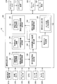
- FIGS. 2 and 3 are explanatory views showing an outline of the operation intervention control executed by the driving support ECU 100.
- FIG. FIGS. 2 and 3 show the steering angle of the steering ST included in the steering device 272 (counterclockwise is the positive direction) and the traveling environment of the vehicle 10 in association with each other. In this traveling environment, the vehicle 10 is traveling from the left side to the right side of the lane defined by the right side wall SW (R) and the left side wall SW (L), and there is an obstacle OB in front of the vehicle 10. is doing.
- 2 and 3 show a safety allowable region SR that is a region in which the behavior of the vehicle 10 should fall in order to ensure the safety of the vehicle 10.
- the driving assistance ECU 100 is permitted at the current time t because the predicted behavior of the vehicle 10 (trajectory in the present embodiment) falls within the safety tolerance region SR over the predicted section (temporal section in the present embodiment).
- An allowable control input range ⁇ safe (specifically, an allowable minimum value ⁇ min and an allowable maximum value ⁇ max of the steering angle ⁇ ), which is a range of operations (the steering angle ⁇ in the present embodiment), is calculated. 2 and 3, the trajectory VP ( ⁇ max ) of the vehicle 10 predicted when the steering angle at the current time t is the allowable maximum value ⁇ max and the steering angle at the current time t are allowable.
- a track VP ( ⁇ min ) of the vehicle 10 predicted when the minimum value ⁇ min is assumed is shown.
- the driving assistance ECU 100 does not perform the operation intervention when the steering angle ⁇ at the current time t is ⁇ 1 which is a value within the allowable control input range ⁇ safe , as in the example of FIG. 2, and the example of FIG. 3.
- the operation intervention is executed when the steering angle ⁇ at the current time t is ⁇ 2, which is a value outside the allowable control input range ⁇ safe .
- the operation intervention control executed by the driving assistance ECU 100 is an “emergency” operation intervention control in which an operation intervention is performed based only on a physical limit using a risk index such as a collision time margin (TTC). In other words, it can be said to be a “normal use” operation intervention control that operates at a stage where an urgent situation has not yet been reached (acts so as to avoid an urgent situation).
- TTC collision time margin
- driving behavior characteristic information DI indicating the driving behavior characteristics of each driver and vehicle characteristic information VI indicating the motion characteristics of the vehicle 10 are referred to.
- reference driving behavior information MI indicating a driving behavior characteristic of an exemplary driver is referred to for setting the safety tolerance region SR. This point will also be described in detail later.
- the driving assistance ECU 100 executes the above-described operation intervention control, as shown in FIG.
- An information storage unit 140 a driving behavior characteristic information management unit 150, an allowable control input range calculation unit 160, an operation intervention determination unit 170, and an operation intervention execution unit 180 are provided.
- the operation intervention execution unit 180 includes an intervention support input determination unit 182.
- the normative driving behavior information storage unit 110 of the driving assistance ECU 100 stores normative driving behavior information MI indicating the driving behavior characteristics of an exemplary driver.
- the safety tolerance region setting unit 120 sets the safety tolerance region SR with reference to the normative driving behavior information MI.
- the vehicle characteristic information storage unit 130 stores vehicle characteristic information VI indicating the movement characteristics of the vehicle 10.
- the driving behavior characteristic information management unit 150 generates and manages driving behavior characteristic information DI indicating the driving behavior characteristics of each driver.
- the driving behavior characteristic information storage unit 140 stores driving behavior characteristic information DI.
- the allowable control input range calculation unit 160 calculates the allowable control input range ⁇ safe .
- the operation intervention determination unit 170 determines whether or not to execute an operation intervention.
- the operation intervention execution unit 180 executes the operation intervention when it is determined to execute the operation intervention.
- the intervention support input determining unit 182 determines an intervention support input that is the degree of intervention when performing the operation intervention.
- the operation intervention control by the driving assistance ECU 100 will be described in more detail.
- the driving behavior characteristic information DI (FIG. 1) stored in the driving behavior characteristic information storage unit 140 is information indicating the driving behavior characteristics of each driver.
- the driving behavior characteristic is a behavior characteristic when each driver drives the vehicle 10, and includes, for example, a characteristic such as what kind of trajectory tends to follow at a certain speed in a certain traveling environment.
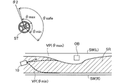
- FIG. 4 is an explanatory diagram illustrating an example of a traveling environment of the vehicle 10.
- the vehicle 10 the center of gravity
- the right side wall SW (R) is present on the right side when viewed from the vehicle 10
- the left side wall SW (L) is present on the left side
- the lane is defined by the two side walls SW.
- a parked vehicle having a length L OB in the x-axis direction and a width W OB in the y-axis direction exists as an obstacle OB at the coordinates (x c , y c ).
- y wr ⁇ 3.5 (m)
- y wl 3.5 (m)
- x c 70 (m)
- y c 1.57 (m)
- L OB 4.80 (m)
- W OB 1.94 (m).
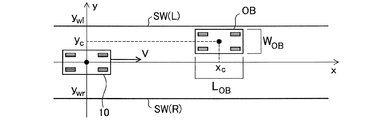
- 5 and 6 are explanatory diagrams showing an example of driving behavior characteristics of each driver.
- 5 shows a trajectory curve D (A) representing the travel trajectory of the vehicle 10 when the vehicle 10 travels by driving by the driver A in the travel environment shown in FIG.
- a yaw curve Y (A) representing a transition of the yaw of the vehicle 10 at that time is shown.
- FIG. 6 shows a trajectory curve D (B) and a yaw curve Y (B) when the vehicle 10 travels by driving by a driver B different from the driver A in the driving environment shown in FIG. Has been.
- the horizontal axis is the coordinate in the x-axis direction
- the vertical axis is the coordinate in the y-axis direction in the upper diagram
- the yaw angle (rad) of the vehicle 10 in the lower diagram As shown in FIGS. 5 and 6, even when traveling in the same traveling environment, the track curve D and the yaw curve Y may differ from one another depending on the driver. For example, the driver B who takes the driving action shown in FIG. 6 has an earlier start timing of the operation for avoiding the obstacle OB and the change in yaw is smaller than the driver A who takes the driving action shown in FIG. Therefore, it can be said that the vehicle has a driving behavior characteristic that more gently avoids the obstacle OB.
- the obstacle avoidance behavior of each driver is considered to be a manifestation of a sense of risk for the obstacle. Therefore, it is considered that the difference in the obstacle avoidance behavior of each driver, that is, the difference in the driving behavior characteristics is due to the difference in the risk feeling of each driver with respect to the obstacle. Therefore, in this embodiment, as an example of modeling of driving behavior characteristics, each driver's sense of risk is modeled and expressed as a parameter-represented potential function. Specifically, it is as follows.
- the attractive potential function U g from the goal on the straight path the repulsive potential function U w from the left and right boundaries (side walls and white lines) that define the lane, and the repulsive potential function U c from the obstacle OB are respectively.
- the following expressions (1) to (3) can be expressed.
- the attractive potential function U g from the goal is expressed as a linear potential function toward the front assuming that the goal is at infinity in the traveling direction.
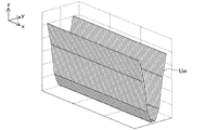
- the repulsive potential function U w from the left and right boundaries is expressed using a one-dimensional Gaussian function, assuming that the boundary length is infinite.
- FIG. 7 shows an example of the repulsive potential function U w from the left and right boundaries in the traveling environment of FIG.
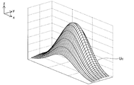
- the repulsive potential function U c from the obstacle OB is expressed using a two-dimensional Gaussian function.
- FIG. 8 shows an example of the repulsive potential function U c from the obstacle OB in the traveling environment of FIG. 7 and 8, the z-axis corresponds to the magnitude of the potential function.
- the magnitude of the attractive force, the magnitude of the repulsive force, the influence range, and the like can be adjusted. For example, when the size of the obstacle OB is different, It can be applied to various situations, such as when there is a difference in risk. In an actual driving environment, a plurality of these factors are combined at the same time. By using the superposition of these three potential functions, the driving behavior of the driver can be expressed.
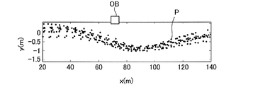
- FIG. 9 shows an example of the distribution of the coordinates P of the vehicle 10 at each time when the vehicle 10 is driven a plurality of times by driving by a driver in the driving environment shown in FIG.
- the parameter estimation problem of the potential function is formulated by the following optimization problem. ⁇ Parameter estimation problem>
- D (x i l , y i l ) is the steepest descent vector of the potential function U at the coordinates (x i l , y i l ).
- the evaluation function J in this optimization problem is the sum of the squares of the differences between the measured velocity vector v and the gradient vector d calculated from the potential field representing the sense of risk.
- the route generated by the potential field obtained as a result of the above optimization is expected to be similar to the driver's avoidance route, and the estimated parameters such as w ci, ⁇ cxi, ⁇ cyi are It is expected to express quantitatively the driver's sense of risk for obstacles in the driving environment.
- the estimated parameters are considered to be specific to the target intention or obstacle, and the same parameters can be used for similar obstacles even in different driving environments.
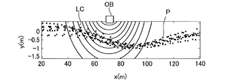
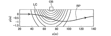
- FIG. 10 shows an example of a contour line LC of the potential field of the identified obstacle.
- the shape of the contour line LC may vary depending on the driver. Note that the evaluation function in the optimization problem for identifying the parameter of the potential function is not limited to the above-described one, and other functions can be taken.
- the driving behavior characteristic information management unit 150 (FIG. 1) of the vehicle 10 accumulates travel data of the vehicle 10 and estimates each parameter value of the potential function based on the accumulated travel data. Further, the driving behavior characteristic information DI for specifying each parameter value is generated and stored in the driving behavior characteristic information storage unit 140.
- the driving behavior characteristic information management unit 150 identifies a driver based on designation via a user interface (not shown) and accumulates driving data for each driver. Further, at a stage where sufficient driving data is not accumulated, for example, driving behavior characteristic information DI representing driving behavior characteristics of an average driver is stored in the driving behavior characteristic information storage unit 140, and sufficient traveling data is accumulated. At this stage, the driving behavior characteristic information DI is updated. Thereafter, the driving behavior characteristic information DI may be updated regularly or irregularly.
- the travel data corresponds to behavior information in the claims.
- the reference trajectory RP is a trajectory of the vehicle 10 in which the risk potential is as low as possible.
- the reference track RP needs to be a track on which the vehicle 10 can actually travel. That is, the vehicle 10 is subjected to nonholonomic restraint, and there is a limit to the steerable steering angle. Therefore, when generating the reference track RP, the vehicle characteristic information VI (FIG. 1) indicating the movement characteristic of the vehicle 10 stored in the vehicle characteristic information storage unit 130 is referred to.
- the vehicle characteristic information VI includes a vehicle movement characteristic model obtained by modeling the movement characteristic of the vehicle 10.
- a vehicle motion characteristic model there are a known two-wheel model represented by the following equations (8) to (10) and a known tire model represented by the following equations (11) to (12). used.
- This optimization problem is an optimization problem for searching for a front wheel steering angle and a state that minimizes a risk potential in a solution space that can be realized by a vehicle motion characteristic model.
- a reference trajectory RP is generated by the following procedure. By repeating this procedure, the path (x k , y k ) (k ⁇ ⁇ 1,2,3, ..., K ⁇ ) matched to the potential field is referenced under the constraint of the motion characteristic model of the vehicle 10 It is generated as a trajectory RP.
- FIG. 11 shows an example of the generated reference trajectory RP. • Step 1: Set the initial value.
- Step 2 Solve the above optimization problem, and calculate ⁇ k + 1 that advances the vehicle 10 in the direction of the lowest potential while satisfying the constraints of the vehicle motion characteristic model in the potential field adapted to each driver. .
- Step 3 Based on the obtained ⁇ k + 1 , the states x k + 1 , y k + 1 , ⁇ k + 1 at the next step are calculated based on the motion characteristic model of the vehicle 10.
- the safety tolerance region SR is set with reference to the normative driving behavior information MI (FIG. 1) stored in the normative driving behavior information storage unit 110.
- the normative driving behavior information MI is information indicating the driving behavior characteristics of an exemplary driver (for example, an instructor at a driving school), and in this embodiment, information indicating each parameter value of the potential function for the exemplary driver. (That is, exemplary driving behavior characteristic information DI of a driver).
- the normative driving behavior information MI corresponds to the specific driving behavior information in the claims.
- FIG. 12 is an explanatory diagram illustrating an example of a method for setting the safety tolerance region SR.
- FIG. 12 shows a reference trajectory RP generated using each parameter value of the potential function for an exemplary driver.
- This reference track RP can be said to be an exemplary track of the vehicle 10 in the specific traveling environment in which the reference track RP is generated.
- an area including the reference trajectory RP and having a width calculated in consideration of dispersion is set as the safety allowable area SR.
- the safety tolerance region SR corresponds to a predetermined region in the claims.
- the allowable control input range ⁇ safe is such that the trajectory of the vehicle 10 predicted with reference to the driving behavior characteristic information DI and the vehicle characteristic information VI falls within the safety allowable region SR over the prediction interval.
- the range of the steering angle allowed at the current time t (the minimum allowable value ⁇ min and the maximum allowable value ⁇ max of the steering angle ⁇ ).
- the allowable control input range calculation unit 160 sets the allowable control input range ⁇ safe by solving the following allowable control input range calculation problem from the viewpoint of satisfaction of constraints. ⁇ Allowable control input range calculation problem>
- Operation intervention judgment and operation intervention execution Next, operation intervention determination by the operation intervention determination unit 170 (FIG. 1) and operation intervention execution by the operation intervention execution unit 180 will be described.
- Operating the intervention determination unit 170 determines whether ⁇ steering angle at the current time t is in the allowable control input range ⁇ in safe, the steering angle ⁇ is in the allowable control input range ⁇ within safe at the present time t In this case, it is determined not to perform the operation intervention, and when the steering angle ⁇ at the current time t is outside the allowable control input range ⁇ safe , it is determined to perform the operation intervention.
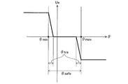
- FIG. 13 is an explanatory diagram illustrating an example of a method for determining the intervention support input Ua.
- the intervention support input Ua is preliminarily set in both cases where the steering angle ⁇ at the current time t is larger than the allowable maximum value ⁇ max and when the steering angle ⁇ at the current time t is smaller than the allowable minimum value ⁇ min. It is determined to be a fixed value.
- This value is variably set according to the driving ability of each driver.
- the steering angle ⁇ in order to smooth the operation feeling and further reduce the driver's uncomfortable feeling, the steering angle ⁇ also in the transition area ⁇ tra which is the area near the boundary on both sides in the allowable control input range ⁇ safe .
- the operation intervention is executed with the intervention support input Ua according to the above. That is, in the example of FIG. 13, the operation intervention is not performed when the steering angle ⁇ at the current time t is in a region other than the transition region ⁇ tra within the allowable control input range ⁇ safe .
- the operation intervention execution unit 180 performs an operation intervention on steering with the intervention support input Ua determined by the intervention support input determination unit 182 via the steering ECU 270.
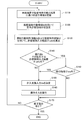
- FIG. 14 is a flowchart showing the flow of the operation intervention control process by the driving assistance ECU 100 of the present embodiment.
- the driving assistance ECU 100 indicates a detection result of a lane boundary or an obstacle, a driving operation, a vehicle speed, a yaw rate, and the like from the driving operation detection unit 210, the vehicle speed sensor 220, the yaw rate sensor 230, the radar unit 250, the camera unit 260, and the like.
- Information is acquired and the traveling environment of the vehicle 10 is grasped (S110).
- the safety permissible area setting unit 120 sets the safety permissible area SR (see FIG. 12) according to the grasped driving environment using the normative driving behavior information MI (step S120).
- the allowable control input range calculation unit 160 calculates the allowable control input range ⁇ safe (see FIGS. 2 and 3) using the driving behavior characteristic information DI and the vehicle characteristic information VI (S130).
- the operation intervention determination unit 170 determines in real time whether or not the operation (steering angle ⁇ ) at the current time t is within the allowable control input range ⁇ safe (S140). When it is determined that the steering angle ⁇ at the current time t is outside the allowable control input range ⁇ safe (S140: NO), the intervention support input determination unit 182 determines the intervention support input Ua (S150), The operation intervention execution unit 180 executes the operation intervention with the determined intervention support input Ua (S160).
- the operation intervention determination unit 170 shifts the steering angle ⁇ at the current time t. It is determined whether or not it is within the region ⁇ tra (see FIG. 13) (S142). When it is determined that the steering angle ⁇ at the current time t is within the transition region ⁇ tra (S142: YES), the intervention support input determination unit 182 determines the intervention support input Ua (S150), and the operation intervention is performed. The unit 180 executes the operation intervention with the determined intervention support input Ua (S160). If it is determined that the rudder angle ⁇ at the current time t is within the allowable control input range ⁇ safe (S140: YES) and outside the transition region ⁇ tra (S142: NO), S150 and S160 Processing is skipped.
- the driving support ECU 100 repeatedly executes the above-described processes from S110 to S160 while an instruction to end the process is not received (S170: NO). When an instruction to end the process is received (S170: YES), the driving support ECU 100 ends the operation intervention control process.
- the safety allowable region setting unit 120 sets the safety allowable region SR that is a region related to the track of the vehicle 10, and the allowable control input range calculation unit 160 Of the steering angle ⁇ permitted at the current time t so that the trajectory of the vehicle 10 predicted using the driving behavior characteristic information DI indicating the driving behavior characteristics of the driver of the driver falls within the safety tolerance region SR over the predetermined prediction section.
- the allowable control input range ⁇ safe that is the range is calculated, and the operation intervention determination unit 170 determines whether or not the steering angle ⁇ at the current time t is within the allowable control input range ⁇ safe , and at the current time t.
- the operation intervention execution unit 180 executes an operation intervention regarding steering.
- the driving support ECU 100 uses the driving behavior characteristic information DI for the trajectory prediction of the vehicle 10 for calculating the allowable control input range ⁇ safe while ensuring the safety by the operation intervention. Therefore, the driver's uncomfortable feeling due to the operation intervention can be further reduced as compared with the conventional configuration in which it is determined whether or not the operation intervention is executed by a uniform determination method.
- the safety allowable region SR is set using the normative driving behavior information MI which is the exemplary driving behavior characteristic information DI of the driver, the driver is exemplified by the operation intervention. Safe driving behavior can be ensured, and safety can be more reliably achieved.
- the driving behavior characteristic information management unit 150 accumulates and accumulates driving data (behavior information) indicating the behavior of the vehicle 10 while the vehicle 10 is traveling in association with the driver. Because driving behavior characteristic information DI is generated using the travel data, it is possible to create driving behavior characteristic information DI that accurately reflects the driving behavior characteristics of the driver, and more effective driver discomfort due to operation intervention. Can be reduced.
- the vehicle characteristic information VI indicating the movement characteristic of the vehicle 10 is used for the trajectory prediction of the vehicle 10 for calculating the allowable control input range ⁇ safe , and thus the movement characteristic of the vehicle 10 is calculated. Therefore, it is possible to predict an appropriate trajectory in consideration of the above, and to ensure both safety and reduction of discomfort at a high level.
- the intervention support input determining unit 182 can variably determine the intervention support input Ua, so that the operation is performed with an appropriate intervention support input Ua according to the driving ability of the driver. Intervention can be performed.
- the trajectory of the vehicle 10 predicted when the allowable control input range calculation unit 160 calculates the allowable control input range ⁇ safe is a trajectory when no operation intervention is performed. Compared with the trajectory prediction when the operation intervention is performed, the trajectory prediction can be performed with high accuracy, and as a result, the determination of whether or not the operation intervention can be performed can be performed with high accuracy.
- the operation intervention control for the steering of the vehicle 10 has been described.
- the present invention is also applied to the operation intervention control for the braking of the vehicle 10, for example, when the vehicle 10 is temporarily stopped at an intersection with poor visibility. Is possible.
- the present invention is applied to the operation intervention control for braking, for example, it is as follows.
- FIG. 15 is an explanatory diagram illustrating an example of a method of setting the safety tolerance region SR in the modification.
- the vertical axis represents the speed of the vehicle 10 and the horizontal axis represents the distance from the intersection.
- a stop line SL exists at a position 5 (m) before the intersection.
- FIG. 15 shows a reference track RP generated using exemplary driver travel data, and a safety tolerance region SR for a vehicle speed set with a certain width in the reference track RP.
- the operation intervention control for acceleration may be executed. For example, when it is determined that the vehicle speed falls below the safety tolerance region SR in the predicted section, an operation intervention that increases the depression angle of the accelerator pedal may be performed.
- the present invention not only the operation intervention regarding steering but also the operation intervention regarding braking and acceleration, it is possible to further reduce the driver's uncomfortable feeling while ensuring safety by the operation intervention. it can.
- the configuration of the vehicle 10 in the above embodiment is merely an example, and the vehicle 10 may not include some of the components described above, or the vehicle 10 may include components not described above.
- the model representing the driving behavior characteristic of the driver described in the above embodiment is merely an example, and other models such as a hybrid dynamic system model may be employed.
- the model representing the vehicle motion characteristics described in the above embodiment is merely an example, and other models such as a steady circle turning model and a constant velocity model may be employed.
- the intervention support input Ua is determined to be a predetermined constant value outside the allowable control input range ⁇ safe (see FIG. 13), but the intervention support input Ua is steered at the current time. It may be changed according to the angle ⁇ .
- the operation intervention an acceptable control input range theta within safe may be not executed at all.
- the safety tolerance region SR is set using the normative driving behavior information MI that is the driving behavior characteristic information DI of the exemplary driver.
- the safe allowable area SR may be set using the driving behavior characteristic information DI. Further, it is not always necessary to use the driving behavior characteristic information DI when setting the safety tolerance region SR. If the behavior of the vehicle 10 is set to be within the range in order to ensure the safety of the vehicle 10, the safety tolerance region is set.
- An arbitrary method can be adopted as the SR setting method.
- the prediction interval is a temporal interval, but the prediction interval may be a distance interval.
- the driving assistance ECU 100 executes the operation intervention control in the normal range that operates in a situation where an emergency has not yet been reached.
- the driving assistance ECU 100 adds, for example, a collision time margin (TTC). It is also possible to execute an emergency operation intervention control in which an operation intervention is performed based only on physical limits using a risk index such as).
- Vehicle 100 Driving support ECU 110: Standard driving behavior information storage unit 120: Safety tolerance region setting unit 130: Vehicle characteristic information storage unit 140: Driving behavior characteristic information storage unit 150: Driving behavior characteristic information management unit 160: Permissible control Input range calculation unit 170: operation intervention determination unit 180: operation intervention execution unit 182: intervention support input determination unit 210: driving operation detection unit 220: vehicle speed sensor 230: yaw rate sensor 240: GPS 250: radar unit 260: camera unit 270: Steering ECU 272: Steering device 280: Brake ECU 282: Brake device DI: Driving behavior characteristic information MI: Standard driving behavior information VI: Vehicle characteristic information
Landscapes
- Engineering & Computer Science (AREA)
- Transportation (AREA)
- Mechanical Engineering (AREA)
- Automation & Control Theory (AREA)
- Physics & Mathematics (AREA)
- Mathematical Physics (AREA)
- Chemical & Material Sciences (AREA)
- Combustion & Propulsion (AREA)
- General Physics & Mathematics (AREA)
- Human Computer Interaction (AREA)
- Control Of Driving Devices And Active Controlling Of Vehicle (AREA)
- Traffic Control Systems (AREA)
- Steering Control In Accordance With Driving Conditions (AREA)
Priority Applications (3)
| Application Number | Priority Date | Filing Date | Title |
|---|---|---|---|
| US15/561,093 US20180118200A1 (en) | 2015-03-27 | 2016-03-14 | Driving assistance device |
| EP16772224.8A EP3276589B1 (en) | 2015-03-27 | 2016-03-14 | Driving assistance device |
| CN201680018276.XA CN107408344B (zh) | 2015-03-27 | 2016-03-14 | 驾驶辅助设备 |
Applications Claiming Priority (2)
| Application Number | Priority Date | Filing Date | Title |
|---|---|---|---|
| JP2015065761A JP6315827B2 (ja) | 2015-03-27 | 2015-03-27 | 運転支援装置 |
| JP2015-065761 | 2015-03-27 |
Publications (1)
| Publication Number | Publication Date |
|---|---|
| WO2016158341A1 true WO2016158341A1 (ja) | 2016-10-06 |
Family
ID=57005664
Family Applications (1)
| Application Number | Title | Priority Date | Filing Date |
|---|---|---|---|
| PCT/JP2016/057927 Ceased WO2016158341A1 (ja) | 2015-03-27 | 2016-03-14 | 運転支援装置 |
Country Status (5)
| Country | Link |
|---|---|
| US (1) | US20180118200A1 (enExample) |
| EP (1) | EP3276589B1 (enExample) |
| JP (1) | JP6315827B2 (enExample) |
| CN (1) | CN107408344B (enExample) |
| WO (1) | WO2016158341A1 (enExample) |
Cited By (3)
| Publication number | Priority date | Publication date | Assignee | Title |
|---|---|---|---|---|
| CN110121449A (zh) * | 2017-01-11 | 2019-08-13 | 本田技研工业株式会社 | 车辆控制装置、车辆控制方法及车辆控制程序 |
| US20210150225A1 (en) * | 2019-11-15 | 2021-05-20 | Honda Motor Co., Ltd. | System and method for providing an interpretable and unified representation for trajectory prediction |
| JP2022038621A (ja) * | 2020-08-27 | 2022-03-10 | いすゞ自動車株式会社 | 自動運転装置 |
Families Citing this family (9)
| Publication number | Priority date | Publication date | Assignee | Title |
|---|---|---|---|---|
| CN110382320A (zh) * | 2017-04-25 | 2019-10-25 | 北川博隆 | 使用重力场理论的车辆自动运行计算算法 |
| JP6845083B2 (ja) * | 2017-05-18 | 2021-03-17 | トヨタ自動車株式会社 | 運転支援装置 |
| JP2019028524A (ja) * | 2017-07-26 | 2019-02-21 | 本田技研工業株式会社 | 制御装置 |
| KR102005900B1 (ko) * | 2017-11-30 | 2019-08-01 | 주식회사 만도 | 차량의 전방 및 측방 충돌 가능성을 기초로 어시스트 토크를 조정하는 전동식 조향 장치 및 방법 |
| US11400927B2 (en) * | 2018-01-29 | 2022-08-02 | Ford Global Technologies, Llc | Collision avoidance and mitigation |
| CN114502335B (zh) * | 2019-10-03 | 2024-07-12 | 三菱电机株式会社 | 用于具有几何约束的非线性机器人系统的轨迹优化的方法和系统 |
| JP7384258B1 (ja) | 2022-09-26 | 2023-11-21 | いすゞ自動車株式会社 | 自動運転装置 |
| JP7687377B1 (ja) | 2023-12-06 | 2025-06-03 | いすゞ自動車株式会社 | 自動運転装置及び自動運転方法 |
| JP2026007932A (ja) * | 2024-07-04 | 2026-01-19 | Astemo株式会社 | 車両制御装置、車両制御方法 |
Citations (3)
| Publication number | Priority date | Publication date | Assignee | Title |
|---|---|---|---|---|
| JP2009298355A (ja) * | 2008-06-17 | 2009-12-24 | Nissan Motor Co Ltd | 車両用障害物回避支援装置及び車両用障害物回避支援方法 |
| WO2011074115A1 (ja) * | 2009-12-18 | 2011-06-23 | トヨタ自動車株式会社 | 走行制御装置 |
| JP2012108653A (ja) * | 2010-11-16 | 2012-06-07 | Toyota Motor Corp | 運転支援装置 |
Family Cites Families (11)
| Publication number | Priority date | Publication date | Assignee | Title |
|---|---|---|---|---|
| JP4062310B2 (ja) * | 2005-02-07 | 2008-03-19 | 日産自動車株式会社 | 運転意図推定装置、車両用運転操作補助装置および車両用運転操作補助装置を備えた車両 |
| JP4466571B2 (ja) * | 2005-05-12 | 2010-05-26 | 株式会社デンソー | ドライバ状態検出装置、車載警報装置、運転支援システム |
| WO2007077867A1 (ja) * | 2005-12-28 | 2007-07-12 | National University Corporation Nagoya University | 運転行動推定装置、運転支援装置、車両評価システム、ドライバモデル作成装置、及び運転行動判定装置 |
| JP5205997B2 (ja) * | 2008-02-06 | 2013-06-05 | 日産自動車株式会社 | 車両用運転操作支援装置 |
| JP2009220605A (ja) * | 2008-03-13 | 2009-10-01 | Aisin Aw Co Ltd | 運転支援装置、運転支援方法および運転支援プログラム |
| JP4541428B2 (ja) * | 2008-05-28 | 2010-09-08 | ヒロセ電機株式会社 | 平型導体用電気コネクタ |
| JP5200732B2 (ja) * | 2008-07-29 | 2013-06-05 | 日産自動車株式会社 | 走行制御装置、及び走行制御方法 |
| DE102010045694A1 (de) * | 2010-09-16 | 2012-03-22 | Daimler Ag | Verfahren zur Vermeidung von Kollisionen eines Fahrzeugs mit Hindernissen |
| DE102012010130A1 (de) * | 2012-05-23 | 2012-12-13 | Daimler Ag | Verfahren zum Ermitteln von kollisionsgefährdenden Lenkwinkelwerteneines Kraftfahrzeuges unter Berücksichtigung eines dynamischen Abstandsgrenzwerts |
| WO2015134311A1 (en) * | 2014-03-03 | 2015-09-11 | Inrix Inc | Traffic obstruction detection |
| US9248834B1 (en) * | 2014-10-02 | 2016-02-02 | Google Inc. | Predicting trajectories of objects based on contextual information |
-
2015
- 2015-03-27 JP JP2015065761A patent/JP6315827B2/ja not_active Expired - Fee Related
-
2016
- 2016-03-14 WO PCT/JP2016/057927 patent/WO2016158341A1/ja not_active Ceased
- 2016-03-14 US US15/561,093 patent/US20180118200A1/en not_active Abandoned
- 2016-03-14 EP EP16772224.8A patent/EP3276589B1/en not_active Not-in-force
- 2016-03-14 CN CN201680018276.XA patent/CN107408344B/zh not_active Expired - Fee Related
Patent Citations (3)
| Publication number | Priority date | Publication date | Assignee | Title |
|---|---|---|---|---|
| JP2009298355A (ja) * | 2008-06-17 | 2009-12-24 | Nissan Motor Co Ltd | 車両用障害物回避支援装置及び車両用障害物回避支援方法 |
| WO2011074115A1 (ja) * | 2009-12-18 | 2011-06-23 | トヨタ自動車株式会社 | 走行制御装置 |
| JP2012108653A (ja) * | 2010-11-16 | 2012-06-07 | Toyota Motor Corp | 運転支援装置 |
Non-Patent Citations (1)
| Title |
|---|
| See also references of EP3276589A4 * |
Cited By (5)
| Publication number | Priority date | Publication date | Assignee | Title |
|---|---|---|---|---|
| CN110121449A (zh) * | 2017-01-11 | 2019-08-13 | 本田技研工业株式会社 | 车辆控制装置、车辆控制方法及车辆控制程序 |
| US20210150225A1 (en) * | 2019-11-15 | 2021-05-20 | Honda Motor Co., Ltd. | System and method for providing an interpretable and unified representation for trajectory prediction |
| US11527073B2 (en) * | 2019-11-15 | 2022-12-13 | Honda Motor Co., Ltd. | System and method for providing an interpretable and unified representation for trajectory prediction |
| JP2022038621A (ja) * | 2020-08-27 | 2022-03-10 | いすゞ自動車株式会社 | 自動運転装置 |
| JP7314883B2 (ja) | 2020-08-27 | 2023-07-26 | いすゞ自動車株式会社 | 自動運転装置 |
Also Published As
| Publication number | Publication date |
|---|---|
| EP3276589A1 (en) | 2018-01-31 |
| EP3276589A4 (en) | 2019-01-02 |
| US20180118200A1 (en) | 2018-05-03 |
| CN107408344A (zh) | 2017-11-28 |
| EP3276589B1 (en) | 2021-11-17 |
| JP6315827B2 (ja) | 2018-04-25 |
| JP2016186683A (ja) | 2016-10-27 |
| CN107408344B (zh) | 2021-07-06 |
Similar Documents
| Publication | Publication Date | Title |
|---|---|---|
| JP6315827B2 (ja) | 運転支援装置 | |
| US9566981B2 (en) | Method and system for post-collision manoeuvre planning and vehicle equipped with such system | |
| DE112012007183B4 (de) | Fahrunterstützungsvorrichtung und Fahrunterstützungsverfahren | |
| CN109664885B (zh) | 车载交通辅助 | |
| US9405727B2 (en) | Driving support device, driving support method, and driving support program | |
| CN102076541B (zh) | 用于自动车道居中和车道变换控制系统的路径生成算法 | |
| KR101480610B1 (ko) | 차량의 충돌 방지 장치 및 그 방법 | |
| EP2615598A1 (en) | Vehicle with computing means for monitoring and predicting traffic participant objects | |
| CN111247045A (zh) | 车辆控制装置 | |
| CN112242069A (zh) | 一种确定车速的方法和装置 | |
| CN110709911A (zh) | 行驶辅助装置的行驶辅助方法以及行驶辅助装置 | |
| CN116390879A (zh) | 用于避免即将发生的碰撞的系统和方法 | |
| JP7364111B2 (ja) | 処理方法、処理システム、処理プログラム | |
| CN103153746A (zh) | 驾驶辅助系统和驾驶辅助方法 | |
| KR20170046483A (ko) | 자율 비상 제동 장치 및 방법 | |
| KR20190045308A (ko) | 차량 판정 방법, 주행 경로 보정 방법, 차량 판정 장치, 및 주행 경로 보정 장치 | |
| JP6838769B2 (ja) | 周辺環境認識装置、表示制御装置 | |
| WO2022158272A1 (ja) | 処理方法、処理システム、処理プログラム、処理装置 | |
| JP2010039718A (ja) | 車両制御装置、車両制御方法および車両制御処理プログラム | |
| JP6372964B2 (ja) | 車両の走行レーン監視方法および制御器 | |
| JP2023505700A (ja) | 車両の軌道を予測するためのシステムおよび方法 | |
| Silberling et al. | Development and application of a collision avoidance capability metric | |
| Raksincharoensak et al. | Vehicle motion planning and control for autonomous driving intelligence system based on risk potential optimization framework | |
| JP4923766B2 (ja) | 車両用制動力制御装置 | |
| CN118701108B (zh) | 一种自动驾驶车辆的控制方法、装置、介质及电子设备 |
Legal Events
| Date | Code | Title | Description |
|---|---|---|---|
| 121 | Ep: the epo has been informed by wipo that ep was designated in this application |
Ref document number: 16772224 Country of ref document: EP Kind code of ref document: A1 |
|
| DPE1 | Request for preliminary examination filed after expiration of 19th month from priority date (pct application filed from 20040101) | ||
| WWE | Wipo information: entry into national phase |
Ref document number: 15561093 Country of ref document: US |
|
| NENP | Non-entry into the national phase |
Ref country code: DE |