WO2016148189A1 - 二軸延伸ブロー成形装置 - Google Patents
二軸延伸ブロー成形装置 Download PDFInfo
- Publication number
- WO2016148189A1 WO2016148189A1 PCT/JP2016/058319 JP2016058319W WO2016148189A1 WO 2016148189 A1 WO2016148189 A1 WO 2016148189A1 JP 2016058319 W JP2016058319 W JP 2016058319W WO 2016148189 A1 WO2016148189 A1 WO 2016148189A1
- Authority
- WO
- WIPO (PCT)
- Prior art keywords
- blow
- fixing plate
- fixing member
- blow molding
- blow core
- Prior art date
- Legal status (The legal status is an assumption and is not a legal conclusion. Google has not performed a legal analysis and makes no representation as to the accuracy of the status listed.)
- Ceased
Links
Images


Classifications
-
- B—PERFORMING OPERATIONS; TRANSPORTING
- B29—WORKING OF PLASTICS; WORKING OF SUBSTANCES IN A PLASTIC STATE IN GENERAL
- B29C—SHAPING OR JOINING OF PLASTICS; SHAPING OF MATERIAL IN A PLASTIC STATE, NOT OTHERWISE PROVIDED FOR; AFTER-TREATMENT OF THE SHAPED PRODUCTS, e.g. REPAIRING
- B29C49/00—Blow-moulding, i.e. blowing a preform or parison to a desired shape within a mould; Apparatus therefor
- B29C49/08—Biaxial stretching during blow-moulding
- B29C49/10—Biaxial stretching during blow-moulding using mechanical means for prestretching
- B29C49/12—Stretching rods
- B29C49/1202—Means for fixing the stretching rod to the driving means, e.g. clamping means or bayonet connections
-
- B—PERFORMING OPERATIONS; TRANSPORTING
- B29—WORKING OF PLASTICS; WORKING OF SUBSTANCES IN A PLASTIC STATE IN GENERAL
- B29C—SHAPING OR JOINING OF PLASTICS; SHAPING OF MATERIAL IN A PLASTIC STATE, NOT OTHERWISE PROVIDED FOR; AFTER-TREATMENT OF THE SHAPED PRODUCTS, e.g. REPAIRING
- B29C49/00—Blow-moulding, i.e. blowing a preform or parison to a desired shape within a mould; Apparatus therefor
- B29C49/08—Biaxial stretching during blow-moulding
- B29C49/10—Biaxial stretching during blow-moulding using mechanical means for prestretching
- B29C49/122—Drive means therefor
- B29C49/1226—Mechanical
-
- B—PERFORMING OPERATIONS; TRANSPORTING
- B29—WORKING OF PLASTICS; WORKING OF SUBSTANCES IN A PLASTIC STATE IN GENERAL
- B29C—SHAPING OR JOINING OF PLASTICS; SHAPING OF MATERIAL IN A PLASTIC STATE, NOT OTHERWISE PROVIDED FOR; AFTER-TREATMENT OF THE SHAPED PRODUCTS, e.g. REPAIRING
- B29C49/00—Blow-moulding, i.e. blowing a preform or parison to a desired shape within a mould; Apparatus therefor
- B29C49/28—Blow-moulding apparatus
- B29C49/28006—Blow-moulding apparatus having special frame
-
- B—PERFORMING OPERATIONS; TRANSPORTING
- B29—WORKING OF PLASTICS; WORKING OF SUBSTANCES IN A PLASTIC STATE IN GENERAL
- B29C—SHAPING OR JOINING OF PLASTICS; SHAPING OF MATERIAL IN A PLASTIC STATE, NOT OTHERWISE PROVIDED FOR; AFTER-TREATMENT OF THE SHAPED PRODUCTS, e.g. REPAIRING
- B29C49/00—Blow-moulding, i.e. blowing a preform or parison to a desired shape within a mould; Apparatus therefor
- B29C49/42—Component parts, details or accessories; Auxiliary operations
- B29C49/4236—Drive means
- B29C49/4237—Pneumatic drive means
-
- B—PERFORMING OPERATIONS; TRANSPORTING
- B29—WORKING OF PLASTICS; WORKING OF SUBSTANCES IN A PLASTIC STATE IN GENERAL
- B29C—SHAPING OR JOINING OF PLASTICS; SHAPING OF MATERIAL IN A PLASTIC STATE, NOT OTHERWISE PROVIDED FOR; AFTER-TREATMENT OF THE SHAPED PRODUCTS, e.g. REPAIRING
- B29C49/00—Blow-moulding, i.e. blowing a preform or parison to a desired shape within a mould; Apparatus therefor
- B29C49/02—Combined blow-moulding and manufacture of the preform or the parison
- B29C2049/023—Combined blow-moulding and manufacture of the preform or the parison using inherent heat of the preform, i.e. 1 step blow moulding
-
- B—PERFORMING OPERATIONS; TRANSPORTING
- B29—WORKING OF PLASTICS; WORKING OF SUBSTANCES IN A PLASTIC STATE IN GENERAL
- B29C—SHAPING OR JOINING OF PLASTICS; SHAPING OF MATERIAL IN A PLASTIC STATE, NOT OTHERWISE PROVIDED FOR; AFTER-TREATMENT OF THE SHAPED PRODUCTS, e.g. REPAIRING
- B29C49/00—Blow-moulding, i.e. blowing a preform or parison to a desired shape within a mould; Apparatus therefor
- B29C49/42—Component parts, details or accessories; Auxiliary operations
- B29C49/48—Moulds
- B29C2049/4879—Moulds characterised by mould configurations
- B29C2049/4881—Moulds characterised by mould configurations having a mandrel or core e.g. two mould halves with a core in-between
-
- B—PERFORMING OPERATIONS; TRANSPORTING
- B29—WORKING OF PLASTICS; WORKING OF SUBSTANCES IN A PLASTIC STATE IN GENERAL
- B29C—SHAPING OR JOINING OF PLASTICS; SHAPING OF MATERIAL IN A PLASTIC STATE, NOT OTHERWISE PROVIDED FOR; AFTER-TREATMENT OF THE SHAPED PRODUCTS, e.g. REPAIRING
- B29C49/00—Blow-moulding, i.e. blowing a preform or parison to a desired shape within a mould; Apparatus therefor
- B29C49/42—Component parts, details or accessories; Auxiliary operations
- B29C49/48—Moulds
- B29C2049/4879—Moulds characterised by mould configurations
- B29C2049/4887—Mould halves consisting of an independent neck and main part
-
- B—PERFORMING OPERATIONS; TRANSPORTING
- B29—WORKING OF PLASTICS; WORKING OF SUBSTANCES IN A PLASTIC STATE IN GENERAL
- B29C—SHAPING OR JOINING OF PLASTICS; SHAPING OF MATERIAL IN A PLASTIC STATE, NOT OTHERWISE PROVIDED FOR; AFTER-TREATMENT OF THE SHAPED PRODUCTS, e.g. REPAIRING
- B29C49/00—Blow-moulding, i.e. blowing a preform or parison to a desired shape within a mould; Apparatus therefor
- B29C49/42—Component parts, details or accessories; Auxiliary operations
- B29C49/78—Measuring, controlling or regulating
- B29C49/786—Temperature
- B29C2049/7861—Temperature of the preform
- B29C2049/7862—Temperature of the preform characterised by temperature values or ranges
-
- B—PERFORMING OPERATIONS; TRANSPORTING
- B29—WORKING OF PLASTICS; WORKING OF SUBSTANCES IN A PLASTIC STATE IN GENERAL
- B29C—SHAPING OR JOINING OF PLASTICS; SHAPING OF MATERIAL IN A PLASTIC STATE, NOT OTHERWISE PROVIDED FOR; AFTER-TREATMENT OF THE SHAPED PRODUCTS, e.g. REPAIRING
- B29C49/00—Blow-moulding, i.e. blowing a preform or parison to a desired shape within a mould; Apparatus therefor
- B29C49/42—Component parts, details or accessories; Auxiliary operations
- B29C49/78—Measuring, controlling or regulating
- B29C2049/7879—Stretching, e.g. stretch rod
-
- B—PERFORMING OPERATIONS; TRANSPORTING
- B29—WORKING OF PLASTICS; WORKING OF SUBSTANCES IN A PLASTIC STATE IN GENERAL
- B29C—SHAPING OR JOINING OF PLASTICS; SHAPING OF MATERIAL IN A PLASTIC STATE, NOT OTHERWISE PROVIDED FOR; AFTER-TREATMENT OF THE SHAPED PRODUCTS, e.g. REPAIRING
- B29C2949/00—Indexing scheme relating to blow-moulding
- B29C2949/07—Preforms or parisons characterised by their configuration
- B29C2949/0715—Preforms or parisons characterised by their configuration the preform having one end closed
-
- B—PERFORMING OPERATIONS; TRANSPORTING
- B29—WORKING OF PLASTICS; WORKING OF SUBSTANCES IN A PLASTIC STATE IN GENERAL
- B29C—SHAPING OR JOINING OF PLASTICS; SHAPING OF MATERIAL IN A PLASTIC STATE, NOT OTHERWISE PROVIDED FOR; AFTER-TREATMENT OF THE SHAPED PRODUCTS, e.g. REPAIRING
- B29C49/00—Blow-moulding, i.e. blowing a preform or parison to a desired shape within a mould; Apparatus therefor
- B29C49/02—Combined blow-moulding and manufacture of the preform or the parison
- B29C49/06—Injection blow-moulding
-
- B—PERFORMING OPERATIONS; TRANSPORTING
- B29—WORKING OF PLASTICS; WORKING OF SUBSTANCES IN A PLASTIC STATE IN GENERAL
- B29C—SHAPING OR JOINING OF PLASTICS; SHAPING OF MATERIAL IN A PLASTIC STATE, NOT OTHERWISE PROVIDED FOR; AFTER-TREATMENT OF THE SHAPED PRODUCTS, e.g. REPAIRING
- B29C49/00—Blow-moulding, i.e. blowing a preform or parison to a desired shape within a mould; Apparatus therefor
- B29C49/08—Biaxial stretching during blow-moulding
- B29C49/10—Biaxial stretching during blow-moulding using mechanical means for prestretching
- B29C49/122—Drive means therefor
- B29C49/1222—Pneumatic
-
- B—PERFORMING OPERATIONS; TRANSPORTING
- B29—WORKING OF PLASTICS; WORKING OF SUBSTANCES IN A PLASTIC STATE IN GENERAL
- B29C—SHAPING OR JOINING OF PLASTICS; SHAPING OF MATERIAL IN A PLASTIC STATE, NOT OTHERWISE PROVIDED FOR; AFTER-TREATMENT OF THE SHAPED PRODUCTS, e.g. REPAIRING
- B29C49/00—Blow-moulding, i.e. blowing a preform or parison to a desired shape within a mould; Apparatus therefor
- B29C49/08—Biaxial stretching during blow-moulding
- B29C49/10—Biaxial stretching during blow-moulding using mechanical means for prestretching
- B29C49/122—Drive means therefor
- B29C49/123—Electric drives, e.g. linear motors
-
- B—PERFORMING OPERATIONS; TRANSPORTING
- B29—WORKING OF PLASTICS; WORKING OF SUBSTANCES IN A PLASTIC STATE IN GENERAL
- B29C—SHAPING OR JOINING OF PLASTICS; SHAPING OF MATERIAL IN A PLASTIC STATE, NOT OTHERWISE PROVIDED FOR; AFTER-TREATMENT OF THE SHAPED PRODUCTS, e.g. REPAIRING
- B29C49/00—Blow-moulding, i.e. blowing a preform or parison to a desired shape within a mould; Apparatus therefor
- B29C49/28—Blow-moulding apparatus
- B29C49/30—Blow-moulding apparatus having movable moulds or mould parts
- B29C49/38—Blow-moulding apparatus having movable moulds or mould parts mounted on movable endless supports
-
- B—PERFORMING OPERATIONS; TRANSPORTING
- B29—WORKING OF PLASTICS; WORKING OF SUBSTANCES IN A PLASTIC STATE IN GENERAL
- B29C—SHAPING OR JOINING OF PLASTICS; SHAPING OF MATERIAL IN A PLASTIC STATE, NOT OTHERWISE PROVIDED FOR; AFTER-TREATMENT OF THE SHAPED PRODUCTS, e.g. REPAIRING
- B29C49/00—Blow-moulding, i.e. blowing a preform or parison to a desired shape within a mould; Apparatus therefor
- B29C49/42—Component parts, details or accessories; Auxiliary operations
- B29C49/48—Moulds
- B29C49/48185—Moulds with more than one separate mould cavity
Definitions
- the present invention relates to a biaxial stretch blow molding apparatus for forming a hollow container by blow molding while stretching a preform with a stretch rod.
- a biaxial stretch blow molding apparatus is known as an apparatus for producing a hollow container made of a synthetic resin such as a plastic container.
- the preform is conveyed to the blow mold by the rotating disk while the neck portion is held, and the preform is stretched by the stretch rod in the blow mold, and the mouth portion.
- the hollow container is blow-molded by feeding high-pressure air into the preform through a blow core mold that closes the (opening). Thereby, a hollow container of a desired shape can be formed.
- a core fixing plate having a blow core mold fixed by a first air cylinder provided in the fixed block is moved up and down (advanced and retracted) together with the lifting block, and is provided in the lifting block.
- a lifting plate to which a stretching rod is fixed is moved up and down by a second air cylinder (see, for example, Patent Document 1).
- the stretch rod When forming a hollow container with such a biaxial stretch blow molding apparatus, the stretch rod is moved (lowered) by the second air cylinder in a state where movement (for example, lowering) of the blow core mold is stopped. . Since air compresses and expands, it is difficult to perform fine speed control only with an air cylinder. For this reason, for example, in the apparatus described in Patent Document 1, if the first air cylinder and the second air cylinder are to be operated synchronously, there is a possibility that the apparatus may be damaged due to the timing shift. .
- the stretching rod is stretched at the standby (rising) position before the blow core mold is lowered so that it is inserted to the vicinity of the bottom of the preform.
- the rod is lowered in advance to a predetermined position corresponding to the length of the preform. That is, in the standby position, the extending rod protrudes below the blow core mold by a predetermined length. Thereby, the cycle time concerning blow molding can be shortened.
- the drive source of the blow core type and the stretching rod is changed from a pneumatic cylinder to a servo motor to shorten the cycle time.
- a first servo motor and a second servo motor are provided, and the first servo motor is driven when the second servo motor is stopped to advance and retract the blow core fixing plate and the extending rod fixing plate.
- the second servo motor is driven when the first servo motor is stopped, so that the stretch rod fixing plate is moved forward and backward independently (see, for example, Patent Document 2).
- the time required for the blow core mold and the lifting rod to be raised and lowered is shortened by moving the blow core mold and the lifting rod back and forth using the servo motor, so that the cycle time can be shortened.
- the present invention has been made in view of such circumstances, and biaxially-stretched blow that can efficiently move the blow core mold and the stretch rod back and forth to shorten the cycle time and stabilize the molding operation.
- An object is to provide a molding apparatus.
- a blow-core fixing member to which a blow-core mold is fixed and a stretching rod fixing member to which a stretching rod is fixed are moved forward and backward.
- a biaxial stretch blow molding apparatus comprising: a second drive means for moving forward and backward independently of the blow core fixing member. .
- the second driving means includes a servo motor, and the servo motor is fixed to the upper base.
- the second drive means includes a slide shaft that linearly moves in the axial direction by rotation of the servo motor, and the slide One end of the shaft is connected to the stretch rod fixing member, and the biaxial stretch blow molding apparatus is characterized.
- the first driving means includes an air cylinder, and the air cylinder is fixed to the upper base. It is in the biaxial stretch blow molding apparatus characterized by being made.
- the stretch rod fixing member contacts the blow core fixing member when driven backward.
- the biaxial stretch blow molding apparatus is characterized by being arranged as described above.
- the blow core fixing member to which the blow core mold is fixed and the stretch rod fixing member to which the stretch rod is fixed can be driven forward and backward independently. Therefore, the blow core fixing member and the extending rod fixing member can be efficiently advanced and retracted at the same timing. Therefore, it is possible to shorten the time required for the movement (advancing and retreating) of the blow core fixing member and the stretching rod fixing member, and hence the cycle time required for blue molding.
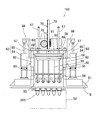
- an injection blow molding apparatus 1 is a so-called one-stage injection blow molding apparatus, which manufactures a hollow container made of a synthetic resin such as a beverage bottle.
- an injection molding device injection molding station
- a temperature control device temperature control station
- a biaxial stretch blow molding device blow molding station
- take-out An apparatus take-out station 6
- the injection molding device 3 is connected to a nozzle 7 of the injection device, and the injection molding device 3 performs injection molding of the preform.
- the temperature control device 4 the temperature of the preform is adjusted to a desired temperature
- the biaxial stretch blow molding device 5 the preform whose temperature is adjusted is biaxially stretch blow molded to form a hollow container which is a final molded product. .
- the hollow container thus formed is taken out by the take-out device 6.
- a turntable 8 is provided above the injection molding device 3, the temperature control device 4, the biaxial stretch blow molding device 5 and the take-out device 6, a turntable 8 is provided.
- the turntable 8 can rotate intermittently with respect to the machine base 2, for example, in the counterclockwise direction.
- the lip mold 9 is provided at four locations in the circumferential direction of the turntable 8, and the preform and the hollow container are sequentially transported to a predetermined apparatus by intermittent rotation of the turntable 8 with the neck portion held by the lip mold 9. It is like that.
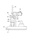
- FIG. 2 is a plan view showing a configuration of a main part of the biaxial stretch blow molding apparatus 5, in particular, a drive mechanism part
- FIG. 3 is a side view thereof.
- the biaxial stretch blow molding apparatus 5 has a blow cavity mold 52 below the upper base 51. Since the blow cavity mold 52 has an existing configuration, detailed description and illustration are omitted, but the blow cavity mold 52 has a pair of split molds, and each of the hollow containers, which are final molded products, is located at a position corresponding to each lip mold 9. A molding space (cavity) corresponding to the shape is formed.
- a blow core fixing plate (blow core fixing member) 54 to which a blow core mold 53 is fixed and a drawing rod fixing plate (extension rod fixing member) to which a drawing rod 55 is fixed are provided on the upper base 51 of the biaxial drawing blow molding apparatus 5.
- 56 is provided.
- a drive mechanism unit 100 for moving the blow core fixing plate 54 and the extending rod fixing plate 56 back and forth is provided.
- the “advance and retreat movement” refers to a movement for moving the blow core fixing plate 54 and the stretching rod fixing plate 56 toward the blow cavity mold 52 and a movement for moving the blow core fixing plate 56 away from the blow cavity mold 52.
- Blow core molds 53 are fixed to the blow core fixing plate 54 at positions corresponding to the plurality of lip molds 9, respectively.
- the blow core fixing plate 54 can be moved back and forth with respect to the blow cavity mold 52 by the drive mechanism unit 100.
- the blow core fixing plate 54 can be moved up and down (lifted and lowered).
- a pair of first guide shafts 57 are erected on both sides of the blow core fixing plate 54, respectively. That is, two first guide shafts 57 are provided side by side on the side of the blow core fixing plate 54, and a total of four first guide shafts 57 are erected on the upper base 51. .
- a plate-shaped reinforcing frame 58 is provided behind the first guide shaft 57 (on the right side in FIG. 2).
- a support member 59 is fixed to the tip portions (upper end portions) of the four first guide shafts 57 and the reinforcing frame 58.
- side plates 60 are provided at both ends of the blow core fixing plate 54, respectively. These side plates 60 are provided to face the two first guide shafts 57 arranged side by side, and the lower ends thereof are fixed to the blow core fixing plate 54. The upper ends of the side plates 60 are connected by a connecting plate 61 arranged in parallel to the blow core fixing plate 54. Further, a slide member 62 slidably mounted on the two opposing first guide shafts 57 is fixed to each side plate 60. That is, the blow core fixing plate 54 is slidably connected to the first guide shaft 57 via the side plate 60 and the slide member 62.
- an air cylinder 63 is provided as a first driving means for moving the blow core fixing plate 54 forward and backward. That is, the blow core fixing plate 54 can be moved by the two air cylinders 63.
- These air cylinders 63 are composed of a cylinder part 64 fixed to the upper base 51 and a drive rod 65 driven in the vertical direction by the cylinder part 64.
- the front end portion of the drive rod 65 is connected to the lower surface of the extending member 66 that extends from the slide member 62 to a position facing the drive rod 65.
- the air cylinder 63 is connected to the blow core fixing plate 54 via the extending member 66, the slide member 62, and the side plate 60.
- one end (upper end) of a plurality of stretching rods 55 corresponding to the plurality of blow core molds 53 is fixed to the stretching rod fixing plate 56.
- the other end (lower end) side of each extending rod is inserted into the blow core mold 53 through a through hole (not shown) formed in the blow core fixing plate 54.
- the extending rod fixing plate 56 is disposed below the connecting plate 61 described above, and can be moved forward and backward with respect to the blow cavity mold 52 by the drive mechanism unit 100 in the same manner as the blow core fixing plate 54. It is configured to be movable (up and down) in the direction.
- second guide shafts 67 are respectively provided in the vicinity of both ends thereof.
- the pair of second guide shafts 67 extends upward from the support member 59.
- a first opening (not shown) is formed in the connecting plate 61 disposed above the extending rod fixing plate 56 so as not to contact the second guide shaft 67.
- the support member 59 is provided with a guide hole 68 through which the second guide shaft 67 is slidably inserted and guides the movement of the second guide shaft 67.
- the guide hole 68 is constituted by a cylindrical guide hole forming member 69 longer than the thickness of the support member 59, and the guide hole forming member 69 is attached to the support member 59.
- the guide hole forming member 69 is attached to the support member 59 so as to protrude by a predetermined amount below the support member 59.
- the connecting plate 61 forms the guide hole.
- the rise of the blow core fixing plate 54 is regulated. That is, in this embodiment, the upper limit position (standby position) of the blow core fixing plate 54 is defined by the guide hole forming member 69.
- the configuration for defining the upper limit position of the blow core fixing plate 54 is not particularly limited.
- a stopper member that restricts the upward movement of the blow core fixing plate 54 may be provided separately from the guide hole forming member 69.
- the stopper member may be provided on a portion of the upper surface of the connecting plate 61 where the second guide shaft 67 does not penetrate, or may be provided on the lower surface of the support member 59.
- a servo motor 70 constituting a second driving means for driving the extending rod fixing plate 56 forward and backward is fixed.
- a drive gear 71 is fixed to the rotation shaft of the servo motor 70, and an extension rack (slide shaft) 73 having a gear portion 72 that engages with the drive gear 71 on one side of the extension rod fixing plate 56 is predetermined. It is provided in length.
- the connecting plate 61 and the support member 59 disposed above the extending rod fixing plate 56 are respectively formed with second openings (not shown) that are large enough not to contact the extending rack 73. Yes.
- the blow core fixing plate 54 and the stretch rod fixing plate 56 can be efficiently moved forward and backward, and the cycle time required for blow molding can be reduced. Shortening can be achieved.
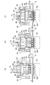
- the blow core fixing plate 54 is raised by the air cylinder 63, and the blow core mold is 53 is held at a position where it does not interfere with the turntable 8.
- the blow core fixing plate 54 is held at a standby position where the connecting plate 61 contacts the guide hole forming member 69.
- the extending rod 55 is held in such a state that its tip (lower end) protrudes about the same as or slightly protrudes from the lower end of the blow core mold 53.
- the tip (lower end) is held in a state where it hardly protrudes from the lower end of the blow core mold 53.
- the blow core mold 53 is disposed at a position relatively close to the blow cavity mold 52 (preform 200).
- the air cylinder 63 is driven to move the drive rod 65 downward (retract).
- the blow core fixing plate 54 is lowered along the first guide shaft 57.
- the blow core fixing plate 54 lowers each blow core mold 53 to a position where the mouth of the preform 200 is sealed.
- the servo motor 70 is driven at the same timing as when the blow core fixing plate 54 is lowered, and the drive gear 71 is rotated in a predetermined direction (clockwise in FIG. 4). As a result, the stretching rod fixing plate 56 is lowered together with the stretching rack 73. The stretching rod fixing plate 56 is lowered to a position where the tip of the stretching rod 55 is near the bottom of the preform 200.
- FIG. 4B shows a state in which the blow core fixing plate 54 is lowered
- FIG. 4C shows a state in which the stretch rod fixing plate 56 is further lowered.
- the plate 54 and the extending rod fixing plate 56 are lowered at the same timing as described above. That is, while the blow core fixing plate 54 is lowered, the stretching rod fixing plate 56 is also lowered.
- the air cylinder 63 as the first driving means for moving the blow core fixing plate 54 forward and backward is fixed to the upper base 51, while the second drive for moving the extending rod fixing plate 56 forward and backward.
- the servo motor 70 constituting the means is fixed to a support member 59. That is, the air cylinder 63 and the servo motor 70 are fixed independently of each other, and one does not affect the operation of the other. Therefore, the air cylinder 63 and the servo motor 70 can be operated at the same timing.
- the encoder and wiring of the servo motor 70 are configured not to receive vibrations or shocks associated with the lifting / lowering operation of the blow core fixing plate 54, and the occurrence of communication abnormality associated therewith is also suppressed. Therefore, the synchronous operation of the biaxial stretch blow molding device 5, for example, the synchronous operation of the rotating disk 8 and the stretch rod fixing plate 56 can be more reliably performed, and the mechanical operation (molding operation) at the time of blow molding. Increased stability.
- the “same timing” means that there is a period in which the stretch rod fixing plate 56 and the blow core fixing plate 54 are moving at the same time, and the servo motor 70 and the air cylinder 63 are not necessarily started simultaneously. Also good.
- the servo motor 70, the air cylinder 63, and the start timing are the rising speeds of the extending rod fixing plate 56 and the blow core fixing plate 54 so that the lowering of the extending rod fixing plate 56 is completed while the blow core fixing plate 54 is lowered. What is necessary is just to determine suitably in consideration.
- the servo motor 70 is driven, the drive gear 71 is rotated in a predetermined direction (clockwise in FIG. 5) to further lower the stretching rod 55, and through the blow core mold 53.
- a high-pressure air is supplied into the preform 200 and blow-molded to form a hollow container 210 having a predetermined shape.
- the servo motor 70 is driven, and the drive gear 71 is rotated in a predetermined direction (counterclockwise in the figure) as shown in FIG. Further, the air cylinder 63 is driven at the same timing as that of the drawing rod fixing plate 56 and the blow core fixing plate 54 is raised.
- the timing at which the blow core fixing plate 54 is raised is preferably at least the timing before the drawing rod fixing plate 56 contacts the connecting plate 61, and more preferably at the same time as the drawing rod fixing plate 56 is raised.
- the extending rod fixing plate 56 contacts the connecting plate 61
- the extending rod fixing plate 56 and the blow core fixing plate 54 rise independently, and the extending rod fixing plate 56 contacts the connecting plate 61.
- the stretch rod fixing plate 56 and the blow core fixing plate 54 rise in synchronization.
- the blow core fixing plate 54 is also pushed up by the extending rod fixing plate 56, that is, lifted by the driving force of the servo motor 70 together with the air cylinder 63, so that the blow core fixing plate 54 and the extending rod fixing plate 56 are moved earlier. It can be raised to the standby position.
- the blow core mold 53 may be tightly fitted to the neck portion of the preform 200, and the raising operation of the blow core mold 53 may be delayed only with the air cylinder.
- the lifting operation of the blow core fixing plate 54 is assisted by the force of the servo motor 70 via the stretching rod fixing plate 56, so that the blow core type 53 operation delays can be suppressed.
- blow core fixing plate 54 and the extending rod fixing plate 56 are raised to the standby position, the air cylinder 63 and the servo motor 70 are stopped, thereby completing the operations of the blow core fixing plate 54 and the extending rod fixing plate 56 in blow molding (one cycle). To do.
- the stretch rod fixing plate 56 can also be lowered independently while the blow core fixing plate 54 is being lowered. For this reason, it is not necessary to make the extending
- the power of the servo motor 70 is used together with the air cylinder 63 when the blow core fixing plate 54 is raised, the time required to raise the blow core fixing plate 54 and the extending rod fixing plate 56 to the standby position is also required. Shortened. Therefore, the cycle time for blow molding can be further shortened.
Landscapes
- Engineering & Computer Science (AREA)
- Manufacturing & Machinery (AREA)
- Mechanical Engineering (AREA)
- Blow-Moulding Or Thermoforming Of Plastics Or The Like (AREA)
- Moulds For Moulding Plastics Or The Like (AREA)
Priority Applications (8)
| Application Number | Priority Date | Filing Date | Title |
|---|---|---|---|
| EP16765018.3A EP3272490B8 (en) | 2015-03-18 | 2016-03-16 | Biaxial stretching and blow molding device |
| CN201680016357.6A CN107428064B (zh) | 2015-03-18 | 2016-03-16 | 双轴拉伸吹塑成型装置 |
| CN202010089084.6A CN111251578B (zh) | 2015-03-18 | 2016-03-16 | 双轴拉伸吹塑成型装置 |
| JP2017506584A JP6420463B2 (ja) | 2015-03-18 | 2016-03-16 | 二軸延伸ブロー成形装置 |
| KR1020197037224A KR102163446B1 (ko) | 2015-03-18 | 2016-03-16 | 2축연신 블로우성형장치 |
| KR1020177029636A KR102079045B1 (ko) | 2015-03-18 | 2016-03-16 | 2축연신 블로우성형장치 |
| US15/706,542 US10532509B2 (en) | 2015-03-18 | 2017-09-15 | Biaxial stretching and blow molding device |
| US16/704,753 US10870231B2 (en) | 2015-03-18 | 2019-12-05 | Biaxial stretching and blow molding device |
Applications Claiming Priority (2)
| Application Number | Priority Date | Filing Date | Title |
|---|---|---|---|
| JP2015-055264 | 2015-03-18 | ||
| JP2015055264 | 2015-03-18 |
Related Child Applications (1)
| Application Number | Title | Priority Date | Filing Date |
|---|---|---|---|
| US15/706,542 Continuation US10532509B2 (en) | 2015-03-18 | 2017-09-15 | Biaxial stretching and blow molding device |
Publications (1)
| Publication Number | Publication Date |
|---|---|
| WO2016148189A1 true WO2016148189A1 (ja) | 2016-09-22 |
Family
ID=56920022
Family Applications (1)
| Application Number | Title | Priority Date | Filing Date |
|---|---|---|---|
| PCT/JP2016/058319 Ceased WO2016148189A1 (ja) | 2015-03-18 | 2016-03-16 | 二軸延伸ブロー成形装置 |
Country Status (7)
| Country | Link |
|---|---|
| US (2) | US10532509B2 (enExample) |
| EP (1) | EP3272490B8 (enExample) |
| JP (2) | JP6420463B2 (enExample) |
| KR (2) | KR102079045B1 (enExample) |
| CN (2) | CN111251578B (enExample) |
| TW (2) | TWI650223B (enExample) |
| WO (1) | WO2016148189A1 (enExample) |
Cited By (4)
| Publication number | Priority date | Publication date | Assignee | Title |
|---|---|---|---|---|
| WO2019078358A1 (ja) | 2017-10-19 | 2019-04-25 | 日精エー・エス・ビー機械株式会社 | 樹脂製の容器の製造方法、金型ユニットおよび成形機 |
| WO2020196462A1 (ja) | 2019-03-26 | 2020-10-01 | 日精エー・エス・ビー機械株式会社 | 射出成形用金型、樹脂製容器製造装置、およびプラグユニット |
| US10870231B2 (en) | 2015-03-18 | 2020-12-22 | Nissei Asb Machine Co., Ltd. | Biaxial stretching and blow molding device |
| US11958230B2 (en) | 2019-09-27 | 2024-04-16 | Nissei Asb Machine Co., Ltd. | Method for producing resin container and device for producing resin container |
Families Citing this family (4)
| Publication number | Priority date | Publication date | Assignee | Title |
|---|---|---|---|---|
| CN112776305A (zh) * | 2019-11-07 | 2021-05-11 | 铨宝工业股份有限公司 | 吹塑成型系统 |
| KR102286242B1 (ko) * | 2019-12-13 | 2021-08-05 | 주식회사 지비피 | 사출-블로우 공정 통합 장치 |
| CN112721107B (zh) * | 2020-12-25 | 2024-09-03 | 佛山市工正包装设备科技股份有限公司 | 一种吹塑模结构 |
| KR20230142080A (ko) | 2022-03-31 | 2023-10-11 | (주)대동테크 | 블로우 성형장치 |
Citations (4)
| Publication number | Priority date | Publication date | Assignee | Title |
|---|---|---|---|---|
| WO1998003324A1 (fr) * | 1996-07-24 | 1998-01-29 | Frontier, Inc. | Machine de moulage a orientation biaxiale |
| JP2004209785A (ja) * | 2002-12-27 | 2004-07-29 | Aoki Technical Laboratory Inc | 延伸ロッドの伸長駆動装置 |
| CN202742661U (zh) * | 2012-09-24 | 2013-02-20 | 张士生 | 一种电机驱动的瓶坯拉伸装置 |
| JP2013539726A (ja) * | 2010-10-15 | 2013-10-28 | アムコー リミテッド | 予備伸縮ロッドアセンブリにより液体流を制御するためのブローノズル |
Family Cites Families (47)
| Publication number | Priority date | Publication date | Assignee | Title |
|---|---|---|---|---|
| US4409161A (en) * | 1981-11-13 | 1983-10-11 | The Continental Group, Inc. | Blow molding method |
| JPH0647270B2 (ja) * | 1989-07-31 | 1994-06-22 | 日精エー・エス・ビー機械株式会社 | 射出延伸吹込成形機 |
| US5182122A (en) * | 1989-08-31 | 1993-01-26 | Nissei Asb Machine Co., Ltd. | Apparatus for stretch blow molding hollow heat-resistant container |
| JPH0675911B2 (ja) * | 1990-08-14 | 1994-09-28 | 日精エー・エス・ビー機械株式会社 | 広口容器の延伸吹込成形方法及び装置 |
| EP0499136A3 (en) * | 1991-02-14 | 1993-06-23 | Husky Injection Molding Systems Ltd. | Servo electric driven stretch rods for blow molding machine |
| US5169705A (en) * | 1991-02-14 | 1992-12-08 | Husky Injection Molding Systems Ltd. | Servo electric driven stretch rods for blow molding machine |
| JP3370124B2 (ja) | 1993-01-28 | 2003-01-27 | 日精エー・エス・ビー機械株式会社 | ブロー成形装置及びブロー成形方法 |
| JP3344595B2 (ja) | 1993-03-02 | 2002-11-11 | 日精エー・エス・ビー機械株式会社 | 二軸延伸ブロー成形装置 |
| JP3391904B2 (ja) * | 1994-07-19 | 2003-03-31 | 日精エー・エス・ビー機械株式会社 | 二軸延伸ブロー成形装置及び方法 |
| CN2206716Y (zh) * | 1994-09-09 | 1995-09-06 | 缪墨龙 | 双列式拉伸吹塑成型机 |
| JP2954858B2 (ja) * | 1994-09-16 | 1999-09-27 | 日精エー・エス・ビー機械株式会社 | 射出延伸ブロー成形装置及び方法 |
| TW508300B (en) * | 1994-09-16 | 2002-11-01 | Asb Co Ltd | Injection-stretch-blow moulding method |
| CH690002A5 (fr) * | 1995-10-10 | 2000-03-15 | Tetra Pak Plastics Ltd Tetra P | Machine pour la fabrication de récipient en matière plastique. |
| DE29619781U1 (de) * | 1996-11-15 | 1997-01-02 | Mauser-Werke GmbH, 50321 Brühl | Blasformmaschine |
| JPH1148316A (ja) * | 1997-08-06 | 1999-02-23 | Tahara:Kk | 2軸延伸吹込成形装置におけるストレッチロッドの制御方法及びその装置 |
| JP2000043131A (ja) * | 1998-08-03 | 2000-02-15 | Tahara:Kk | 二軸延伸ブロー成形方法及びその成形機 |
| US6217819B1 (en) * | 1999-06-07 | 2001-04-17 | Ernst Dieter Wunderlich | Universal single-row and multi-row insert stretch blow molding method and apparatus therefor |
| JP3722671B2 (ja) * | 2000-06-28 | 2005-11-30 | 日精エー・エス・ビー機械株式会社 | 射出延伸ブロー成形装置 |
| JP3668684B2 (ja) * | 2000-12-25 | 2005-07-06 | 日精エー・エス・ビー機械株式会社 | 成形装置及び成形方法 |
| US6713013B2 (en) * | 2002-03-13 | 2004-03-30 | Ernst Dieter Wunderlich | Single-row and multi-row stretch blow molding method and apparatus therefor |
| MXPA05006304A (es) * | 2002-12-12 | 2005-08-29 | A K Tech Lab Inc | Dispositivo de extension de varilla de estiramiento y dispositivo de levantamiento de molde de fondo para maquina de moldeo por soplado de estiramiento. |
| JP2004188866A (ja) * | 2002-12-12 | 2004-07-08 | Aoki Technical Laboratory Inc | 延伸ブロー成形方法及びブロー金型装置 |
| JP2004262052A (ja) | 2003-02-28 | 2004-09-24 | Aoki Technical Laboratory Inc | ブロー成形装置 |
| JP4404678B2 (ja) | 2004-04-15 | 2010-01-27 | 株式会社青木固研究所 | ブローエア供給装置およびブロー成形機 |
| CN100513136C (zh) * | 2004-05-19 | 2009-07-15 | 日精Asb机械株式会社 | 可把持瓶的延伸吹塑成形方法 |
| FR2889671B1 (fr) * | 2005-08-12 | 2009-08-07 | Sidel Sas | Poste de soufflage pour installation d'etirage soufflage de recipients et installation comportant un tel ensemble |
| DE102005055209B3 (de) * | 2005-11-19 | 2007-02-08 | Illig Maschinenbau Gmbh & Co. Kg | Antriebseinrichtung für einen Streckhelfer zum mechanischen Verformen einer Kunststofffolie oder -platte |
| JP4753772B2 (ja) * | 2006-04-10 | 2011-08-24 | 日精エー・エス・ビー機械株式会社 | 射出延伸ブロー成形装置 |
| JP4837442B2 (ja) * | 2006-05-30 | 2011-12-14 | 株式会社青木固研究所 | 射出延伸ブロー成形機 |
| CN101130274A (zh) * | 2006-08-22 | 2008-02-27 | 东莞佳鸿机械制造有限公司 | 吹塑机的瓶胚拉伸吹气装置 |
| EP2117806B1 (de) * | 2007-02-15 | 2016-01-06 | KHS Corpoplast GmbH | Verfahren und vorrichtung zur blasformung von behältern unter verwendung eines servomotors für die reckstange |
| FR2918916B1 (fr) * | 2007-07-19 | 2009-10-23 | Sidel Participations | Installation pour la fabrication de recipients a partir d'une preforme et procede de commande des moyens de soufflage d'une telle installation |
| DE102008005311A1 (de) * | 2008-01-21 | 2009-07-23 | Armin Steinke | Vorrichtung zur Streckblasformung eines Behälters |
| IT1396854B1 (it) * | 2008-07-29 | 2012-12-20 | Sacmi Coop Mecc Imola Societa' Coop | Unita' di formatura di un impianto per il soffiaggio di contenitori di plastica, in particolare bottiglie |
| EP2199061A1 (de) * | 2008-12-19 | 2010-06-23 | Krones AG | Elektrisch betriebene Blasformmaschine und das Verfahren |
| FR2943941B1 (fr) * | 2009-04-02 | 2011-04-22 | Sidel Participations | Unite porte-moule avec tuyere pilotee |
| JP5697885B2 (ja) * | 2009-09-11 | 2015-04-08 | 日精エー・エス・ビー機械株式会社 | ブロー成形機 |
| TWM381512U (en) * | 2010-01-08 | 2010-06-01 | Chumpower Machinery Corp | Drawing lever mechanism of stretch-blow forming machine |
| CN101885234A (zh) * | 2010-07-02 | 2010-11-17 | 郝恩政 | 一步法注拉吹塑料中空成型机 |
| CN201841663U (zh) * | 2010-08-13 | 2011-05-25 | 浙江宏振机械模具集团有限公司 | 整体式往复注塑、吹塑成型机 |
| MY158479A (en) * | 2010-10-25 | 2016-10-14 | Nissei Asb Machine Co Ltd | Injection stretch blow molding device and molded part heating device |
| CN202011144U (zh) * | 2011-01-05 | 2011-10-19 | 周林富 | 并列式二至四工位拉伸气缸吹瓶机 |
| JP5798440B2 (ja) * | 2011-10-18 | 2015-10-21 | 日精エー・エス・ビー機械株式会社 | ブロー型ユニット及びそれを用いたブロー成形機 |
| DE202013009941U1 (de) * | 2012-11-12 | 2013-11-20 | Khs Corpoplast Gmbh | Vorrichtung zur Blasformung von Behältern mit einer Antriebseinrichtung und mit gekoppelten Bewegungsabläufen |
| CN203752495U (zh) * | 2014-02-25 | 2014-08-06 | 王益 | 一种瓶胚有封口独立气缸和同步拉伸的吹瓶机 |
| CN104175530A (zh) * | 2014-04-04 | 2014-12-03 | 林玉斋 | 多动板自动制瓶机 |
| JP6420463B2 (ja) | 2015-03-18 | 2018-11-07 | 日精エー・エス・ビー機械株式会社 | 二軸延伸ブロー成形装置 |
-
2016
- 2016-03-16 JP JP2017506584A patent/JP6420463B2/ja active Active
- 2016-03-16 KR KR1020177029636A patent/KR102079045B1/ko active Active
- 2016-03-16 CN CN202010089084.6A patent/CN111251578B/zh active Active
- 2016-03-16 EP EP16765018.3A patent/EP3272490B8/en active Active
- 2016-03-16 CN CN201680016357.6A patent/CN107428064B/zh active Active
- 2016-03-16 KR KR1020197037224A patent/KR102163446B1/ko active Active
- 2016-03-16 WO PCT/JP2016/058319 patent/WO2016148189A1/ja not_active Ceased
- 2016-03-18 TW TW106136238A patent/TWI650223B/zh active
- 2016-03-18 TW TW105108548A patent/TWI610792B/zh active
-
2017
- 2017-09-15 US US15/706,542 patent/US10532509B2/en active Active
-
2018
- 2018-10-11 JP JP2018192712A patent/JP6751739B2/ja active Active
-
2019
- 2019-12-05 US US16/704,753 patent/US10870231B2/en active Active
Patent Citations (4)
| Publication number | Priority date | Publication date | Assignee | Title |
|---|---|---|---|---|
| WO1998003324A1 (fr) * | 1996-07-24 | 1998-01-29 | Frontier, Inc. | Machine de moulage a orientation biaxiale |
| JP2004209785A (ja) * | 2002-12-27 | 2004-07-29 | Aoki Technical Laboratory Inc | 延伸ロッドの伸長駆動装置 |
| JP2013539726A (ja) * | 2010-10-15 | 2013-10-28 | アムコー リミテッド | 予備伸縮ロッドアセンブリにより液体流を制御するためのブローノズル |
| CN202742661U (zh) * | 2012-09-24 | 2013-02-20 | 张士生 | 一种电机驱动的瓶坯拉伸装置 |
Non-Patent Citations (1)
| Title |
|---|
| See also references of EP3272490A4 * |
Cited By (17)
| Publication number | Priority date | Publication date | Assignee | Title |
|---|---|---|---|---|
| US10870231B2 (en) | 2015-03-18 | 2020-12-22 | Nissei Asb Machine Co., Ltd. | Biaxial stretching and blow molding device |
| KR20220056251A (ko) | 2017-10-19 | 2022-05-04 | 닛세이 에이. 에스. 비 기카이 가부시키가이샤 | 수지제 용기의 제조방법, 금형 유닛 및 성형기 |
| EP4338930A2 (en) | 2017-10-19 | 2024-03-20 | Nissei ASB Machine Co., Ltd. | Method for producing resin vessel made of resin, mould unit and moulding apparatus |
| KR20250029991A (ko) | 2017-10-19 | 2025-03-05 | 닛세이 에이. 에스. 비 기카이 가부시키가이샤 | 수지제 용기의 제조방법, 금형 유닛 및 성형기 |
| KR20190087658A (ko) | 2017-10-19 | 2019-07-24 | 닛세이 에이. 에스. 비 기카이 가부시키가이샤 | 수지제 용기의 제조방법, 금형 유닛 및 성형기 |
| KR20210091372A (ko) | 2017-10-19 | 2021-07-21 | 닛세이 에이. 에스. 비 기카이 가부시키가이샤 | 수지제 용기의 제조방법, 금형 유닛 및 성형기 |
| KR20210092332A (ko) | 2017-10-19 | 2021-07-23 | 닛세이 에이. 에스. 비 기카이 가부시키가이샤 | 수지제 용기의 제조방법, 금형 유닛 및 성형기 |
| KR20200037449A (ko) | 2017-10-19 | 2020-04-08 | 닛세이 에이. 에스. 비 기카이 가부시키가이샤 | 수지제 용기의 제조방법, 금형 유닛 및 성형기 |
| US11260575B2 (en) | 2017-10-19 | 2022-03-01 | Nissei Asb Machine Co., Ltd. | Method for producing resin vessel made of resin, mould unit and moulding apparatus |
| KR20220119502A (ko) | 2017-10-19 | 2022-08-29 | 닛세이 에이. 에스. 비 기카이 가부시키가이샤 | 수지제 용기의 제조방법, 금형 유닛 및 성형기 |
| WO2019078358A1 (ja) | 2017-10-19 | 2019-04-25 | 日精エー・エス・ビー機械株式会社 | 樹脂製の容器の製造方法、金型ユニットおよび成形機 |
| KR20250026407A (ko) | 2017-10-19 | 2025-02-25 | 닛세이 에이. 에스. 비 기카이 가부시키가이샤 | 수지제 용기의 제조방법, 금형 유닛 및 성형기 |
| KR20240120758A (ko) | 2017-10-19 | 2024-08-07 | 닛세이 에이. 에스. 비 기카이 가부시키가이샤 | 수지제 용기의 제조방법, 금형 유닛 및 성형기 |
| KR20240091145A (ko) | 2017-10-19 | 2024-06-21 | 닛세이 에이. 에스. 비 기카이 가부시키가이샤 | 수지제 용기의 제조방법, 금형 유닛 및 성형기 |
| US11951664B2 (en) | 2019-03-26 | 2024-04-09 | Nissei Asb Machine Co., Ltd. | Die for injection molding, production apparatus for container made of resin, and plug unit |
| WO2020196462A1 (ja) | 2019-03-26 | 2020-10-01 | 日精エー・エス・ビー機械株式会社 | 射出成形用金型、樹脂製容器製造装置、およびプラグユニット |
| US11958230B2 (en) | 2019-09-27 | 2024-04-16 | Nissei Asb Machine Co., Ltd. | Method for producing resin container and device for producing resin container |
Also Published As
| Publication number | Publication date |
|---|---|
| KR102079045B1 (ko) | 2020-02-19 |
| CN111251578A (zh) | 2020-06-09 |
| CN111251578B (zh) | 2022-04-19 |
| EP3272490A4 (en) | 2018-12-05 |
| JP6420463B2 (ja) | 2018-11-07 |
| TWI650223B (zh) | 2019-02-11 |
| EP3272490A1 (en) | 2018-01-24 |
| KR102163446B1 (ko) | 2020-10-08 |
| US10532509B2 (en) | 2020-01-14 |
| TW201827200A (zh) | 2018-08-01 |
| TWI610792B (zh) | 2018-01-11 |
| US20200108542A1 (en) | 2020-04-09 |
| EP3272490B1 (en) | 2022-01-19 |
| JP2019022991A (ja) | 2019-02-14 |
| KR20180002614A (ko) | 2018-01-08 |
| JP6751739B2 (ja) | 2020-09-09 |
| TW201703976A (zh) | 2017-02-01 |
| KR20190142429A (ko) | 2019-12-26 |
| CN107428064A (zh) | 2017-12-01 |
| CN107428064B (zh) | 2020-02-28 |
| US20180001539A1 (en) | 2018-01-04 |
| JPWO2016148189A1 (ja) | 2018-02-01 |
| EP3272490B8 (en) | 2022-03-16 |
| US10870231B2 (en) | 2020-12-22 |
Similar Documents
| Publication | Publication Date | Title |
|---|---|---|
| JP6420463B2 (ja) | 二軸延伸ブロー成形装置 | |
| US11731337B2 (en) | Blow molding device and blow molding method | |
| CN103874572B (zh) | 吹塑模单元和使用该吹塑模单元的吹塑成形机 | |
| JP7620135B2 (ja) | 樹脂製容器の製造装置及び製造方法 | |
| CN101947852B (zh) | 一种注吹大容量塑料中空容器的模具设备及其工艺方法 | |
| US7874828B2 (en) | Machine for moulding plastic containers using means for moving the mould-support unit comprising two in-line connecting rods | |
| CN108472857B (zh) | 合模装置及方法 | |
| US9962879B2 (en) | Machine for forming containers made of thermoplastic material | |
| CN104139489A (zh) | 一种注塑模内自动贴标设备 |
Legal Events
| Date | Code | Title | Description |
|---|---|---|---|
| 121 | Ep: the epo has been informed by wipo that ep was designated in this application |
Ref document number: 16765018 Country of ref document: EP Kind code of ref document: A1 |
|
| ENP | Entry into the national phase |
Ref document number: 2017506584 Country of ref document: JP Kind code of ref document: A |
|
| NENP | Non-entry into the national phase |
Ref country code: DE |
|
| ENP | Entry into the national phase |
Ref document number: 20177029636 Country of ref document: KR Kind code of ref document: A |
|
| REEP | Request for entry into the european phase |
Ref document number: 2016765018 Country of ref document: EP |