WO2020196462A1 - 射出成形用金型、樹脂製容器製造装置、およびプラグユニット - Google Patents
射出成形用金型、樹脂製容器製造装置、およびプラグユニット Download PDFInfo
- Publication number
- WO2020196462A1 WO2020196462A1 PCT/JP2020/012860 JP2020012860W WO2020196462A1 WO 2020196462 A1 WO2020196462 A1 WO 2020196462A1 JP 2020012860 W JP2020012860 W JP 2020012860W WO 2020196462 A1 WO2020196462 A1 WO 2020196462A1
- Authority
- WO
- WIPO (PCT)
- Prior art keywords
- flow path
- plug
- molten resin
- injection molding
- base member
- Prior art date
Links
- 229920005989 resin Polymers 0.000 title claims abstract description 123
- 239000011347 resin Substances 0.000 title claims abstract description 123
- 238000001746 injection moulding Methods 0.000 title claims abstract description 76
- 238000004519 manufacturing process Methods 0.000 title claims description 22
- 230000002093 peripheral effect Effects 0.000 claims description 25
- 230000000452 restraining effect Effects 0.000 claims description 16
- 230000001629 suppression Effects 0.000 abstract description 3
- 238000002347 injection Methods 0.000 description 31
- 239000007924 injection Substances 0.000 description 31
- 238000000071 blow moulding Methods 0.000 description 29
- 238000000465 moulding Methods 0.000 description 29
- 239000000463 material Substances 0.000 description 16
- 238000001816 cooling Methods 0.000 description 11
- 230000014759 maintenance of location Effects 0.000 description 10
- 238000000034 method Methods 0.000 description 10
- 238000005553 drilling Methods 0.000 description 7
- 238000009792 diffusion process Methods 0.000 description 6
- 230000001965 increasing effect Effects 0.000 description 6
- 238000004904 shortening Methods 0.000 description 5
- 238000010586 diagram Methods 0.000 description 4
- 238000003754 machining Methods 0.000 description 4
- 238000007664 blowing Methods 0.000 description 3
- 238000005304 joining Methods 0.000 description 3
- 238000012545 processing Methods 0.000 description 3
- 230000006866 deterioration Effects 0.000 description 2
- 239000002184 metal Substances 0.000 description 2
- 229920000139 polyethylene terephthalate Polymers 0.000 description 2
- 239000005020 polyethylene terephthalate Substances 0.000 description 2
- 230000008569 process Effects 0.000 description 2
- 238000005452 bending Methods 0.000 description 1
- 230000008859 change Effects 0.000 description 1
- 238000005520 cutting process Methods 0.000 description 1
- 238000013461 design Methods 0.000 description 1
- 230000002542 deteriorative effect Effects 0.000 description 1
- 238000009826 distribution Methods 0.000 description 1
- 238000011143 downstream manufacturing Methods 0.000 description 1
- 230000003028 elevating effect Effects 0.000 description 1
- 238000000605 extraction Methods 0.000 description 1
- 230000020169 heat generation Effects 0.000 description 1
- 230000006872 improvement Effects 0.000 description 1
- 230000006698 induction Effects 0.000 description 1
- 238000010102 injection blow moulding Methods 0.000 description 1
- 238000003780 insertion Methods 0.000 description 1
- 230000037431 insertion Effects 0.000 description 1
- 238000012986 modification Methods 0.000 description 1
- 230000004048 modification Effects 0.000 description 1
- 239000012768 molten material Substances 0.000 description 1
- 239000004033 plastic Substances 0.000 description 1
- 229920003023 plastic Polymers 0.000 description 1
- 229920001225 polyester resin Polymers 0.000 description 1
- 239000004645 polyester resin Substances 0.000 description 1
- -1 polyethylene terephthalate Polymers 0.000 description 1
- 238000003672 processing method Methods 0.000 description 1
- 239000002994 raw material Substances 0.000 description 1
- 230000009467 reduction Effects 0.000 description 1
- 230000000717 retained effect Effects 0.000 description 1
- 238000007493 shaping process Methods 0.000 description 1
- 229920003002 synthetic resin Polymers 0.000 description 1
- 239000000057 synthetic resin Substances 0.000 description 1
- 229920005992 thermoplastic resin Polymers 0.000 description 1
Images


Classifications
-
- B—PERFORMING OPERATIONS; TRANSPORTING
- B29—WORKING OF PLASTICS; WORKING OF SUBSTANCES IN A PLASTIC STATE IN GENERAL
- B29C—SHAPING OR JOINING OF PLASTICS; SHAPING OF MATERIAL IN A PLASTIC STATE, NOT OTHERWISE PROVIDED FOR; AFTER-TREATMENT OF THE SHAPED PRODUCTS, e.g. REPAIRING
- B29C45/00—Injection moulding, i.e. forcing the required volume of moulding material through a nozzle into a closed mould; Apparatus therefor
- B29C45/17—Component parts, details or accessories; Auxiliary operations
- B29C45/26—Moulds
- B29C45/27—Sprue channels ; Runner channels or runner nozzles
- B29C45/2725—Manifolds
-
- B—PERFORMING OPERATIONS; TRANSPORTING
- B29—WORKING OF PLASTICS; WORKING OF SUBSTANCES IN A PLASTIC STATE IN GENERAL
- B29C—SHAPING OR JOINING OF PLASTICS; SHAPING OF MATERIAL IN A PLASTIC STATE, NOT OTHERWISE PROVIDED FOR; AFTER-TREATMENT OF THE SHAPED PRODUCTS, e.g. REPAIRING
- B29C45/00—Injection moulding, i.e. forcing the required volume of moulding material through a nozzle into a closed mould; Apparatus therefor
- B29C45/17—Component parts, details or accessories; Auxiliary operations
- B29C45/26—Moulds
- B29C45/27—Sprue channels ; Runner channels or runner nozzles
- B29C45/30—Flow control means disposed within the sprue channel, e.g. "torpedo" construction
-
- B—PERFORMING OPERATIONS; TRANSPORTING
- B29—WORKING OF PLASTICS; WORKING OF SUBSTANCES IN A PLASTIC STATE IN GENERAL
- B29C—SHAPING OR JOINING OF PLASTICS; SHAPING OF MATERIAL IN A PLASTIC STATE, NOT OTHERWISE PROVIDED FOR; AFTER-TREATMENT OF THE SHAPED PRODUCTS, e.g. REPAIRING
- B29C49/00—Blow-moulding, i.e. blowing a preform or parison to a desired shape within a mould; Apparatus therefor
- B29C49/02—Combined blow-moulding and manufacture of the preform or the parison
- B29C49/06—Injection blow-moulding
-
- B—PERFORMING OPERATIONS; TRANSPORTING
- B29—WORKING OF PLASTICS; WORKING OF SUBSTANCES IN A PLASTIC STATE IN GENERAL
- B29C—SHAPING OR JOINING OF PLASTICS; SHAPING OF MATERIAL IN A PLASTIC STATE, NOT OTHERWISE PROVIDED FOR; AFTER-TREATMENT OF THE SHAPED PRODUCTS, e.g. REPAIRING
- B29C45/00—Injection moulding, i.e. forcing the required volume of moulding material through a nozzle into a closed mould; Apparatus therefor
- B29C45/17—Component parts, details or accessories; Auxiliary operations
- B29C45/26—Moulds
- B29C2045/2683—Plurality of independent mould cavities in a single mould
-
- B—PERFORMING OPERATIONS; TRANSPORTING
- B29—WORKING OF PLASTICS; WORKING OF SUBSTANCES IN A PLASTIC STATE IN GENERAL
- B29C—SHAPING OR JOINING OF PLASTICS; SHAPING OF MATERIAL IN A PLASTIC STATE, NOT OTHERWISE PROVIDED FOR; AFTER-TREATMENT OF THE SHAPED PRODUCTS, e.g. REPAIRING
- B29C45/00—Injection moulding, i.e. forcing the required volume of moulding material through a nozzle into a closed mould; Apparatus therefor
- B29C45/17—Component parts, details or accessories; Auxiliary operations
- B29C45/26—Moulds
- B29C45/27—Sprue channels ; Runner channels or runner nozzles
- B29C45/2701—Details not specific to hot or cold runner channels
- B29C2045/2717—Reconfigurable runner channels
-
- B—PERFORMING OPERATIONS; TRANSPORTING
- B29—WORKING OF PLASTICS; WORKING OF SUBSTANCES IN A PLASTIC STATE IN GENERAL
- B29C—SHAPING OR JOINING OF PLASTICS; SHAPING OF MATERIAL IN A PLASTIC STATE, NOT OTHERWISE PROVIDED FOR; AFTER-TREATMENT OF THE SHAPED PRODUCTS, e.g. REPAIRING
- B29C45/00—Injection moulding, i.e. forcing the required volume of moulding material through a nozzle into a closed mould; Apparatus therefor
- B29C45/17—Component parts, details or accessories; Auxiliary operations
- B29C45/26—Moulds
- B29C45/27—Sprue channels ; Runner channels or runner nozzles
- B29C45/2725—Manifolds
- B29C2045/2733—Inserts, plugs, bushings
-
- B—PERFORMING OPERATIONS; TRANSPORTING
- B29—WORKING OF PLASTICS; WORKING OF SUBSTANCES IN A PLASTIC STATE IN GENERAL
- B29C—SHAPING OR JOINING OF PLASTICS; SHAPING OF MATERIAL IN A PLASTIC STATE, NOT OTHERWISE PROVIDED FOR; AFTER-TREATMENT OF THE SHAPED PRODUCTS, e.g. REPAIRING
- B29C49/00—Blow-moulding, i.e. blowing a preform or parison to a desired shape within a mould; Apparatus therefor
- B29C49/02—Combined blow-moulding and manufacture of the preform or the parison
- B29C2049/023—Combined blow-moulding and manufacture of the preform or the parison using inherent heat of the preform, i.e. 1 step blow moulding
-
- B—PERFORMING OPERATIONS; TRANSPORTING
- B29—WORKING OF PLASTICS; WORKING OF SUBSTANCES IN A PLASTIC STATE IN GENERAL
- B29C—SHAPING OR JOINING OF PLASTICS; SHAPING OF MATERIAL IN A PLASTIC STATE, NOT OTHERWISE PROVIDED FOR; AFTER-TREATMENT OF THE SHAPED PRODUCTS, e.g. REPAIRING
- B29C2949/00—Indexing scheme relating to blow-moulding
- B29C2949/07—Preforms or parisons characterised by their configuration
- B29C2949/076—Preforms or parisons characterised by their configuration characterised by the shape
- B29C2949/0768—Preforms or parisons characterised by their configuration characterised by the shape characterised by the shape of specific parts of preform
- B29C2949/077—Preforms or parisons characterised by their configuration characterised by the shape characterised by the shape of specific parts of preform characterised by the neck
- B29C2949/0771—Wide-mouth
-
- B—PERFORMING OPERATIONS; TRANSPORTING
- B29—WORKING OF PLASTICS; WORKING OF SUBSTANCES IN A PLASTIC STATE IN GENERAL
- B29C—SHAPING OR JOINING OF PLASTICS; SHAPING OF MATERIAL IN A PLASTIC STATE, NOT OTHERWISE PROVIDED FOR; AFTER-TREATMENT OF THE SHAPED PRODUCTS, e.g. REPAIRING
- B29C49/00—Blow-moulding, i.e. blowing a preform or parison to a desired shape within a mould; Apparatus therefor
- B29C49/02—Combined blow-moulding and manufacture of the preform or the parison
- B29C49/06—Injection blow-moulding
- B29C49/061—Injection blow-moulding with parison holding means displaceable between injection and blow stations
- B29C49/062—Injection blow-moulding with parison holding means displaceable between injection and blow stations following an arcuate path, e.g. rotary or oscillating-type
- B29C49/063—Injection blow-moulding with parison holding means displaceable between injection and blow stations following an arcuate path, e.g. rotary or oscillating-type with the parison axis held in the plane of rotation
Definitions
- This disclosure relates to injection molding dies, resin container manufacturing equipment, and plug units.
- the hot parison type blow molding method is a method of blow molding by utilizing the heat retained during injection molding of the preform, and it is possible to manufacture a container having a variety of aesthetic appearances as compared with the cold parison type.
- Patent Documents 1 and 2 the time required for the injection molding mold opening / closing operation and the elevating operation of the stretching device is shortened, in Patent Document 3, the control method of the injection device is changed, and in Patent Document 4, early release is possible.
- the molding cycle is shortened by adopting a preform shape and its injection molding mold.
- Patent Document 5 discloses a manifold device of a hot runner mold in which a branched and bent runner is formed in a manifold (hot runner type) main body.
- Patent Document 6 discloses a manifold provided with a molten material passage formed by smoothly bending by so-called diffusion bonding. The manifolds of Patent Document 5 and Patent Document 6 are used in an injection molding method (injection molding machine).
- a hot runner type is provided between the injection device and the injection cavity type.
- the configuration of the flow path inside the hot runner is greatly affected, and the quality of the preform may be deteriorated. ..
- an object of the present disclosure is to provide an injection molding die (hot runner mold), a resin container manufacturing apparatus, and a plug unit capable of shortening the injection molding time while maintaining the quality of the preform. And.
- the injection molding die of the present disclosure capable of solving the above problems is
- the flow path through which the molten resin passes and A main body having an introduction part for introducing the molten resin into the flow path and a supply part for supplying the molten resin from the flow path to the cavity type.
- An injection molding die including a plug flow path that is a part of the flow path and a plug unit that can be attached to the main body.
- a restraining portion for suppressing the occurrence of pressure loss when the molten resin passes through the flow path is formed in a portion of the plug flow path where the traveling direction of the molten resin changes.
- the injection molding die includes a flow path, a main body portion, and a plug unit that can be attached to the main body portion.
- a restraining portion for suppressing the occurrence of pressure loss when the molten resin passes through the flow path is formed at a portion where the traveling direction of the molten resin changes. .. Therefore, for example, even if the injection pressure of the injection device is increased in order to increase the flow rate of the molten resin, the molten resin is less likely to deteriorate and the quality of the preform is maintained. Further, by increasing the injection pressure of the injection device, the time required for the molten resin to be supplied from the introduction portion to the cavity mold via the flow path is also shortened. As described above, according to the above configuration, it is possible to provide an injection molding die capable of shortening the injection molding time while maintaining the quality of the preform.
- the resin container manufacturing apparatus of the present disclosure capable of solving the above problems is Including the injection molding die according to the present disclosure.
- the plug unit of the present disclosure that can solve the above problems is A plug unit that can be attached to the main body of an injection molding die in which a flow path through which molten resin passes is formed.
- the plug unit has a plug main body portion in which a plug flow path that is a part of the flow path is formed.
- a restraining portion for suppressing the occurrence of pressure loss when the molten resin passes through a part of the plug flow path is formed in a portion of the plug flow path where the traveling direction of the molten resin changes. There is.
- the plug unit has a plug main body portion in which the plug flow path is formed, and the molten resin is placed in the plug flow path in the portion of the plug flow path where the traveling direction of the molten resin changes.
- a restraining portion is formed to suppress the occurrence of pressure loss when passing through a part of the plastic.
- the plug unit can be attached to the main body of the injection molding die. As described above, according to the above configuration, even if the injection molding die is, for example, a gun drilling type injection molding die, a restraining portion can be provided in a part of the flow path.
- an injection molding die hot runner mold
- a resin container manufacturing apparatus a plug unit capable of shortening the injection molding time while maintaining the quality of the preform. ..
- FIG. 1 is a block diagram of a molding machine.
- FIG. 2 is a schematic cross-sectional view illustrating an injection molded portion.
- FIG. 3 is a cross-sectional view of an injection molding die (hot runner mold) according to the present disclosure.
- FIG. 4A is a cross-sectional view of a flow path formed by using a conventional plug unit.
- FIG. 4B is a cross-sectional view of a flow path formed by using a conventional plug unit.
- FIG. 4C is a cross-sectional view of a flow path formed by using the plug unit according to the present disclosure.
- FIG. 5 is a diagram illustrating a flowchart of a method for manufacturing a resin container.
- the “vertical direction” is a direction including the “upward direction” and the “downward direction”.
- the “front-back direction” is a direction including the “forward direction” and the “rear direction”.
- the "left-right direction” is a direction including the "left direction” and the "right direction”.
- the front-rear direction in FIG. 1 corresponds to the longitudinal direction of the molding machine 20.
- Each direction in FIG. 2 is a direction when the injection molding portion 21 is observed from the right side surface.
- FIGS. 4A to 4C are a direction when the hot runner type 60 is observed from above. Further, each direction in FIGS. 4A to 4C is a direction when the plug units 62, 162, 262 are observed from the outside front.
- the configurations of the injection molding die, the resin container manufacturing apparatus, and the plug unit according to the present disclosure are not limited to the definition of the direction in FIGS. 1 to 4C.
- FIG. 1 is a block diagram of the molding machine 20.
- the molding machine 20 includes at least an injection molding unit 21 for manufacturing the preform 11, and an injection device 25 for supplying a resin material as a raw material is connected to the molding machine 20.
- the injection device 25 has a nozzle for injecting the resin material into the injection molding unit 21.
- the molding machine 20 has a temperature control section (post-cooling section) 22 for adjusting or cooling the temperature of the manufactured preform 11 and a preform 11 on the downstream process side of the injection molding section 21 as needed.
- blow molding unit an example of a blow device 23 for blowing the product to manufacture a container
- take-out unit 24 for taking out the manufactured container.
- the injection molding die (hot runner mold 60) of the present disclosure can be used, for example, when the molding machine 20 is a cold parison type injection molding machine or a hot parison type blow molding machine.
- the molding machine 20 may have an injection molding unit 21, a blow molding unit 23, and an extraction unit 24, and may further include a temperature control unit 22. These molded portions are provided at positions rotated by a predetermined angle of 90 degrees or 120 degrees with respect to the conveying means 26.
- the transport means 26 is composed of a rotating plate or the like, and as illustrated in FIG. 2, the preform 11 or the container in a state where the neck portion 12 is supported by the neck mold 50 attached to the rotary plate of the transport means 26. Is configured to be transported to each part as the rotating plate rotates.
- the injection molding unit 21 is an injection molding unit for preform including an injection cavity type 30 (hereinafter, simply referred to as a cavity type 30), an injection core type 40, and a neck type 50. It includes 21A and a runner block type 60A (a part of the hot runner type 60).
- the hot runner mold 60 including the runner block mold 60A is an injection molding die for supplying the molten resin to the injection molding die unit 21A for preform.
- An introduction port 64 (an example of an introduction portion) is provided on the side surface of the runner block type 60A. The introduction port 64 is configured so that the nozzle of the injection device 25 can be brought into contact with the nozzle.
- an introduction flow path 68 extending from the introduction port 64 to the inside of the runner block type 60A is provided inside the runner block type 60A.
- the introduction flow path 68 is a flow path for introducing the molten resin injected from the injection device 25 into the flow path in the runner block type 60A.
- the introduction port 64 may be provided on the lower surface of the runner block type 60A.
- a hollow gate portion 31 is provided on the lower surface of the injection cavity mold 30.
- a hollow runner block nozzle hole 65A connected to the supply unit 65, which will be described later, is provided on the upper surface of the runner block type 60A. The gate portion 31 and the runner block nozzle hole 65A communicate with each other.
- a bottomed preform is formed by pouring a synthetic resin material such as a polyester resin (for example, PET: polyethylene terephthalate) from the injection device 25 into the preform-shaped space formed by molding these molds.
- the resin material is, for example, a thermoplastic resin, and can be appropriately selected depending on the application.
- the resin material injected from the injection device 25 to the injection molding unit 21 is a molten resin (molten resin).
- the preform 11 has an optimum wall thickness distribution (shape) depending on the container, and the body thickness (average thickness, wall thickness) of the preform 11 is, for example, 1.0 to 5.0 mm, preferably 1.5 to. It is set to 3.0 mm.
- the temperature control unit 22 is configured to adjust the temperature of the preform 11 manufactured by the injection molding unit 21 to a temperature suitable for final blowing.
- the blow molding unit 23 is configured to perform blow molding on the temperature-controlled preform 11 in the temperature control unit 22 to manufacture a container.
- the blow molding unit 23 is composed of a bottom mold and a pair of split molds (cavity molds for blow molding) that can be opened and closed.
- the outer shape of the side surface and the bottom surface of the container is defined by molding the bottom mold and the split mold.
- the hot runner type 60 includes a runner block type 60A, a base member 60B, and a plurality of side wall members 60C.
- the runner block type 60A is a block member included in the hot runner type 60.
- the runner block type 60A is attached to the base member 60B and is arranged so as to be surrounded by the plurality of side wall members 60C.
- the runner block type 60A has a main body 61, a plurality of plug units 62, and a plurality of plug units 69.
- the runner block type 60A according to the present embodiment has a total of six plug units, but the number of plug units is not limited to this.
- the main body 61 is a substantially rectangular parallelepiped or a substantially cylindrical body.
- the main body 61 includes a flow path 63, an introduction port 64, and a supply section 65.
- holes are provided on the upper surface and each side surface of the main body 61 for mounting various parts for the runner block type 60A on the runner block type 60A.
- the upper surface of the main body 61 is provided with a hole that functions as a supply 65.
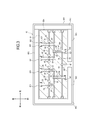
- a hole 601 for inserting the plug units 62 and 69 is provided on the side surface of the main body 61.
- the hole 601 is preferably T-shaped in a cross-sectional view in the front-rear direction, but is not limited thereto. For example, it may have a substantially square shape in cross-sectional view.
- a heater (not shown) is mounted.
- the plug unit 62 has a substantially tubular shape with a hollow inside. Further, the plug unit 62 may be mounted on the runner block type 60A, and the outer shape in the vertical cross-sectional view may be a substantially cylindrical body or a substantially prismatic body.
- the plug unit 62 is preferably T-shaped in cross-sectional view in the front-rear direction, but may be substantially square.
- the plug unit 62 can be attached to the main body 61.
- the plug unit 62 includes a plug main body portion 621 and a fixing portion 622.
- the plug main body 621 has a substantially tubular shape and is substantially rectangular in cross-sectional view. The length of the plug body 621 in the front-rear direction is longer than the length of the plug body 621 in the left-right direction.
- the fixed portion 622 is substantially rectangular in cross-sectional view in the front-rear direction.
- the length of the fixed portion 622 in the front-rear direction is shorter than the length of the fixed portion 622 in the left-right direction.
- the plug unit 69 includes a plug main body portion 691 and a fixing portion 692.
- the plug unit 69 has substantially the same configuration as the plug unit 62, but the linear flow path formed inside the plug unit 69 is larger than the linear flow path formed inside the plug unit 62. Different in the long run.
- the flow path 63 is a passage through which the molten resin introduced from the introduction port 64 can pass.
- the flow path 63 includes a main body flow path 66 formed inside the main body 61, and a plug flow path 67 formed inside the plug main body 621, 691. That is, the main body flow path 66 and the plug flow path 67 are a part of the flow path 63.
- the main body flow path 66 is linear. Therefore, the traveling direction of the molten resin passing through the main body flow path 66 does not change.
- the plug flow path 67 includes not only a linear flow path but also a curved flow path and a bifurcated flow path.
- the plug unit is attached to the main body of the runner block type when the flow path of the runner block type is generally manufactured by gun drilling.
- the first reason is that, for example, when a runner block type flow path is manufactured by diffusion joining, the flow path can be designed relatively freely, so that the flow path can be bent without using a plug unit. Because it can be done.
- the second reason is that when the plug unit is attached to the main body of the runner block type, it is necessary to provide a space for inserting the plug unit inside the runner block type, which causes spatial restrictions. is there.
- a space for example, an insertion hole for attaching the plug unit to the runner block type main body is provided in the runner block type main body. I don't do that.
- plug units are generally used when runner block type flow paths are generally made by gun drilling. Since the flow path 63 of the runner block type 60A according to this embodiment is manufactured by using gun drilling, plug units 62 and 69 are used.
- FIGS. 4A to 4C are cross-sectional views of a flow path formed by using the conventional plug unit 162 and a flow path formed by using the plug unit 262, and FIG. 4C is a cross-sectional view of the flow path formed by using the plug unit 62 according to the present disclosure. It is sectional drawing of the formed flow path.
- a flow path 163 is provided inside the plug unit 162.
- the flow path 163 is composed of a plurality of linear flow paths and is substantially L-shaped. Corner portions 164 and 165 are formed at the contact points of the linear flow paths.
- the corner portion 164 has an end portion 164A, an end portion 164B, and an inclined portion 164C.
- the angle between the end portion 164A and the end portion 164B in the flow path 163 is approximately 135 degrees, respectively.
- the angle of the corner portion 164 in the flow path 163 is approximately 90 degrees.
- the angle of the corner portion 165 in the flow path 163 is approximately 270 degrees.
- a substantially right-angled metal portion of the plug unit 162 protrudes toward the flow path side. Further, it is practically impossible to process the corner portion 165 into an inclined portion or a curved portion (in a state where the R value is large) like the corner portion 164.
- a flow path 263 is provided inside the plug unit 262.
- the flow path 263 is composed of a plurality of linear flow paths and is substantially T-shaped.
- a corner portion 265 is formed at the contact point of each linear flow path.
- the angle of the corner portion 265 in the flow path 263 is approximately 270 degrees. That is, it can be said that at the corner portion 265, a substantially right-angled metal portion of the plug unit 262 protrudes toward the flow path side. Further, it is practically impossible to process the corner portion 265 into an inclined portion or a curved portion (in a state where the R value is large) like the corner portion 164 of the plug unit 162.
- the molten resin passes through the flow path near the corners 164, 165, 265, the molten resin tends to stay or drift at the corners 164, 165, 265. Further, in the flow path near the corners 164, 165, 265, the flow resistance to the molten resin becomes large, and thus the pressure loss becomes large. In particular, at the corner portions 165 and 265 where the inclined portion and the curved portion cannot be formed, retention and drift of the molten resin are likely to occur, and the pressure loss is large. In the conventional plug unit 162 and plug unit 262, a substantially L-shaped flow path and a substantially T-shaped flow path cannot be integrally formed inside them. Therefore, when the conventional plug unit 162 and the plug unit 262 are used, the main body flow path 66 may be different from that in FIG.
- the plug unit 62 includes a first base member 62A, a second base member 62B, and a third base member 62C.
- the first base member 62A, the second base member 62B, and the third base member 62C are independent of each other. Therefore, the plug unit 62 may include, for example, only the first base member 62A and the third base member 62C.
- the first base member 62A is formed with a straight portion 70 in which the molten resin travels straight.
- the second base member 62B is formed with a curved portion 71, which is a portion where the traveling direction of the molten resin changes.
- the third base member 62C is formed with a branch portion 72 which is a portion where the traveling direction of the molten resin branches (changes).
- the straight portion 70, the curved portion 71, and the branch portion 72 can function as a part of the plug flow path 67.
- the plug unit 69 similarly to the plug unit 62, the first base member having a straight portion, the second base member having a curved portion, and the third base member having a branch portion formed therein. , Is equipped.
- the straight portion 70 is formed by drilling the first base member 62A.
- the curved portion 71 is formed by subjecting the second base member 62B to a machining process.
- the branch portion 72 is formed by subjecting the third base member 62C to a machining process.
- a curved surface 73 is formed on the outer portion of the inner peripheral surface of the curved portion 71 (the outer portion of the center line M which is a set of midpoints of the plug flow path 67).
- a curved surface 74 is formed on the inner portion (inner portion of the center line M) on the inner peripheral surface of the curved portion 71. Therefore, the radius of curvature of the curved surface 73 is larger than the radius of curvature of the curved surface 74.
- the branch portion 72 includes at least a first flow path 72A and a second flow path 72B. Therefore, in the branch portion 72, the plug flow path 67 branches in at least two different directions.
- a curved surface 75 is formed on the outer portion (outer portion of the center line M) on the inner peripheral surface of the first flow path 72A.
- a curved surface 76 is formed on the inner portion (inner portion of the center line M) on the inner peripheral surface of the first flow path 72A. Therefore, the radius of curvature of the curved surface 75 is larger than the radius of curvature of the curved surface 76.
- a curved surface 77 is formed on the outer portion (outer portion of the center line M) on the inner peripheral surface of the second flow path 72B.
- a curved surface 78 is formed on the inner portion (inner portion of the center line M) on the inner peripheral surface of the second flow path 72B. Therefore, the radius of curvature of the curved surface 77 is larger than the radius of curvature of the curved surface 78.
- a sharpened portion 79 is formed at the boundary between the curved surface 75 and the curved surface 77.
- the apex of the pointed portion 79 is pointed toward the front direction of the plug unit 62 (the direction opposite to the traveling direction of the molten resin in the straight portion 70).
- the boundary portion between the curved surface 75 and the curved surface 77 is formed in a pointed shape.
- the pointed portion 79 is on a line extending from the midpoint in the width direction of the straight portion 70 toward the traveling direction of the molten resin. Further, the pointed portion 79 is on a straight line formed by connecting the midpoint of the short side of the third base member 62C and the midpoint of the straight portion 70 in the width direction.
- all the regions corresponding to the corners 165 of the conventional plug unit 162 exemplified in FIG. 4A and the corners 265 of the plug unit 262 exemplified in FIG. 4B are curved. It is composed of surfaces (curved roads). Therefore, the retention, drift, and pressure loss of the molten resin generated at the corners 165 and 265 can be suppressed or reduced.
- the inner diameter of the straight portion 70 and the inner diameter of the curved portion 71 are equal.
- the inner diameter of the first flow path 72A and the inner diameter of the second flow path 72B are equal.
- the inner diameter of the first flow path 72A and the inner diameter of the second flow path 72B are smaller than the inner diameter of the straight portion 70 and the inner diameter of the curved portion 71.
- the branch portion 72 may be provided with a third flow path (not shown) or a fourth flow path (not shown), if necessary.
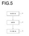
- FIG. 5 is an example of a case where the present disclosure is used in a 4-station type injection blow molding apparatus, and is a diagram illustrating a flowchart of a method for manufacturing a resin container.
- the container has an injection molding step S1 for injection molding the preform 11, a temperature control step S2 for controlling the temperature of the preform 11, and a blow molding step S3 for manufacturing the container by blow molding the temperature-controlled preform 11.
- the container is taken out by opening the neck portion 12 of the container from the neck mold 50.
- a resin material (molten resin) is injected from the injection device 25 into the introduction port 64.
- the molten resin injected toward the introduction port 64 is introduced into the main body flow path 66 formed in the main body portion 61 via the introduction flow path 68.
- the molten resin that has flowed into the main body flow path 66 flows into the plug flow path 67 formed in the plug unit 69 via the main body flow path 66.
- the molten resin that has flowed into the plug flow path 67 passes through the curved portion 71, the straight portion 70, and the branch portion 72 in this order. Since each of the curved surfaces 73 and 74 formed on the inner peripheral surface of the curved portion 71 has a curved shape so that the traveling direction of the molten resin gradually changes, the molten resin is curved when passing through the curved portion 71. The retention and drift of the molten resin in the part 71 are unlikely to occur. Further, in the curved portion 71, the flow resistance to the molten resin is reduced, and thus the pressure loss is also reduced. In this way, each of the curved surfaces 73 and 74 can function as a suppression unit 80 that suppresses the generation of pressure loss and the retention and drift of the molten resin.
- each of the curved surfaces 75 to 78 can function as a suppression unit 80 that suppresses the occurrence of pressure loss. Further, since the sharpened portion 79 is formed at the portion where each of the curved surface 75 and the curved surface 77 is connected, retention, drift, and pressure loss of the molten resin are unlikely to occur even in the vicinity of the sharpened portion 79.
- the molding machine 20 transfers the preform 11 from the injection molding section 21 to a post step, for example, a temperature control section (post-cooling). Part) 22 or move to the blow molding part.
- the injection molding portion 21 including the hot runner mold 60 provided with the runner block mold 60A it is possible to suppress the occurrence of pressure loss generated when the molten resin passes through the curved portion 71 and the branch portion 72. It is possible to reduce the retention and drift of the molten resin. Therefore, even if the injection molding time of the preform is shortened, a high quality preform can be produced. As a result, the time required for the entire molding cycle of the molding machine 20 is also shortened.
- the temperature control step (post-cooling step) S2 will be described.
- the preform 11 is housed in the preform-shaped space of the cavity type 30. Subsequently, air is sent to the inside of the preform 11 housed in the cavity mold 30, and a preliminary blow and a cooling blow are performed to bring the preform 11 into close contact with the inner wall of the cavity mold 30. After cooling for a certain period of time, the cooled preform 11 is moved to the blow molding unit 23. Since the runner block type 60A can form a high-quality preform, the temperature control step (post-cooling step) S2 can be completed in a short time.
- the processing method of the temperature control step (post-cooling step) S2 is not limited to the above.
- the blow molding step S3 will be described.
- the preform is housed in the blow molding portion 23 in a state where the bottom mold is stationary and the split mold is open. Subsequently, the preform 11 is stretched downward by the rod member. Then, the preform 11 is inflated to the shape of the container by the final blow that sends air to the inside of the preform 11, and the container is manufactured. After that, the split mold is opened and the container is opened from the blow molding unit 23.
- the container pulled out from the blow molding part 23 is moved to the take-out part 24 (FIG. 1), and the container is taken out by opening the neck part 12 of the container from the neck mold 50 (FIG. 2).
- a container is manufactured by the above method.
- the gun drill type hot runner is more advantageous in terms of cost than the diffusion joint processing type hot runner, which requires extremely high dimensional accuracy. For this reason, a gun drill type hot runner is generally adopted when a hot parison type blow molding method is used. However, when a gun drill type hot runner is adopted, the runner (flow path) can only be machined in a straight line. Therefore, the shape of the corner portion which is the intersection of the runners and the branch portion of the runner where the flow path branches into two is limited to an L-shape or a T-shape having a substantially right angle shape.
- a curved corner portion or a branch portion having a small pressure loss is formed like a corner portion or a branch portion in a diffusion bonding type hot runner. Can't. This is because when the runner block type flow path is manufactured by gun drilling, the gun drill can only be moved linearly with respect to the runner block type.
- the resin material tends to drift or stay.
- the flow resistance of the resin material increases, which in turn increases the pressure loss.
- the injection pressure of the injection device had to be increased.
- the method of increasing the injection pressure of the injection device causes temperature unevenness of the resin material due to induction of shear heat generation in the runner region such as the corner, the branch, and the narrow part, and as a result, the quality of the resin material deteriorates.
- the preform temperature was increased.
- the injection core type eccentricity is likely to occur, which is one of the causes of the increase in the uneven thickness of the preform.
- the unbalanced temperature and / or uneven thickness is large, the unbalanced temperature and / or uneven thickness of the preform cannot be eliminated with a short temperature control processing time in high-speed molding.
- the runner block type 60A has plug units 62 and 69 that are separate from the main body 61.
- the plug units 62 and 69 have a size of about 1/40 of the size of the runner block type 60A, and can be inserted and held from the external hole 601 of the main body 61. Therefore, when it is desired to form a flow path such as a gently curved curved portion or a branch portion in the runner block type 60A in addition to the linear flow path, the linear flow path is provided in the main body portion 61, and the curved portion or the curved portion or the like.
- the branch portion can be provided in separate plug units 62 and 69.
- a linear flow path can be easily formed by performing a gun drill on the main body 61 as in the conventional case.
- the curved portion and the branched portion can be easily formed into a desired diameter and shape by cutting the inside of the plug units 62 and 69 by machining or the like. Therefore, by making the plug units 62 and 69 forming the plug flow path 67 including the curved portion 71 or the branch portion 72 into a member separate from the main body portion 61, it is not necessary to rely on the diffusion joining processing type.
- the runner block type 60A in which the optimum flow path is configured can be easily realized.
- the plug unit 62 includes a first base member 62A, a second base member 62B, and a third base member 62C.
- the plug unit 69 also includes a first base member in which a straight portion is formed, a second base member in which a curved portion is formed, and a third base member in which a branch portion is formed. Therefore, for example, when it is intended to create a flow path inside the plug unit 62, the inside of each base member may be cut by machining for each base member, so that the inside of the plug unit 62 can be easily formed.
- a plug flow path 67 including a curved portion 71 and a branch portion 72 can be manufactured.
- the runner block mold 60A includes a flow path 63, a main body 61, and a plug unit 62. It has 69 and.
- the restraining portion 80 is formed in the curved portion 71 and the branch portion 72, which are the portions of the plug flow path 67 of the plug unit 62 where the traveling direction of the molten resin changes. Therefore, it is possible to prevent pressure loss and deterioration of the molten resin when the molten resin passes through the curved portion 71 and the branch portion 72.
- the injection pressure does not have to be increased more than necessary. Therefore, it is possible to produce a high-quality preform in which deterioration (burning) of the resin due to retention is suppressed, and uneven temperature and uneven thickness due to a high injection pressure that compensates for the pressure loss are also reduced.
- the curved portion 71 and the branch portion 72 are curved on the inner and outer portions on the inner peripheral surface. Since it is formed as a surface, it is possible to suppress the pressure loss generated when passing through the curved portion 71 and the branched portion 72, and the resin material is less likely to deteriorate.
- a sharpened portion 79 is formed at the boundary between the curved surface 75 and the curved surface 77. ..
- the boundary portion between the curved surface 75 and the curved surface 77 is formed in a pointed shape. Therefore, retention and drift of the molten resin are unlikely to occur in the vicinity of the sharpened portion 79. As a result, the pressure loss generated when the molten resin passes through the branch portion 72 can be reduced, and the resin material is less likely to deteriorate.
- the plug units 62 and 69 are composed of a plurality of base members. Therefore, for example, even if the design of the hot runner type 60 is changed, the length of the plug flow path 67 can be adjusted, and the diameter and radius of curvature of the plug flow path 67 can be processed and / or adjusted quickly and easily. Etc. can be performed.
- the plug unit 62 is the first in which the straight portion 70 is formed. It has a base member 62A, a second base member 62B on which a curved portion 71 is formed, and a third base member 62C on which a branch portion 72 is formed.
- the first base member 62A is arranged between the second base member 62B and the third base member 62C.
- the plug unit 69 as well as the plug unit 62, the first base member in which the straight portion is formed, the second base member in which the curved portion is formed, and the third base member in which the branch portion is formed are formed.
- the first base member is arranged between the second base member and the third base member. Therefore, according to the hot runner type 60, the molding machine 20, and the plug units 62 and 69, the length of the flow path 63 formed in the plug units 62 and 69 and the traveling direction of the flow path 63 can be adjusted. ..
- the present invention is not limited to the above-described embodiment, and can be freely modified, improved, and the like as appropriate.
- the material, shape, size, numerical value, form, number, arrangement location, etc. of each component in the above-described embodiment are arbitrary and are not limited as long as they can achieve the object of the present disclosure.
- the shape of the surface formed on the outer and inner sides of the inner peripheral surface of the curved portion 71 and the branch portion 72 is curved, but is limited to this. Absent. For example, it may be a part of the circumference of a substantially regular polygon.
- the plug unit 62 includes a first base member 62A, a second base member 62B, and a third base member 62C, but the present invention is not limited to this example.
- the plug unit 62 includes, for example, a configuration including a second base member 62B and a third base member 62C, a configuration including a first base member 62A and a second base member 62B, or a configuration including a first base member 62A and a third base member 62C. It may be provided.
- the plug unit 69 also has a configuration including a second base member and a third base member, a configuration including a first base member and a second base member, or a first base member and a third base member. It may be configured to include.
- the molding machine 20 is a so-called 4-station type molding machine in which a temperature control unit 22 is provided between the injection molding unit 21 and the blow molding unit 23.
- the temperature control unit 22 It may be a so-called 2-station type or 3-station type blow molding machine that is not provided with a blow molding unit 23, or an injection molding apparatus that is not provided with a blow molding unit 23.
- the plug flow path has a curved portion in which the traveling direction of the molten resin changes.
- the plug flow path has at least two branching portions that branch in different directions.
- the branch portion includes a first flow path and a second flow path.
- the restraining portion is any one of [1] to [3], which is formed as a curved surface on the inner portion of the inner peripheral surface of the first flow path and the inner portion of the inner peripheral surface of the second flow path, respectively.
- the restraining portion is further formed as a curved surface on an outer portion on the inner peripheral surface of the first flow path and an outer portion on the inner peripheral surface of the second flow path, respectively.
- the plurality of base members are A first base member in which a straight portion in which the molten resin travels straight is formed, A second base member in which a curved portion of the flow path in which the traveling direction of the molten resin changes is formed, and A third base member in which a branch portion in which the traveling direction of the molten resin branches is formed in the flow path, and Have, The injection molding die according to [6], wherein the first base member is arranged between the second base member and the third base member.
- a resin container manufacturing apparatus including the injection molding die according to any one of [1] to [7].
- a plug unit that can be attached to the main body of an injection molding die in which a flow path through which the molten resin passes is formed.
- the plug unit has a plug main body portion in which a plug flow path that is a part of the flow path is formed.
- a restraining portion for suppressing the occurrence of pressure loss when the molten resin passes through a part of the plug flow path is formed in a portion of the plug flow path where the traveling direction of the molten resin changes.
Abstract
溶融樹脂が通過する流路(63)と、溶融樹脂を流路(63)に導入するための導入部および溶融樹脂を流路(63)からキャビティ型(30)へ供給する供給部(65)を有する本体部(61)と、流路(63)の一部であるプラグ流路(67)が形成されているとともに、本体部(61)に対して取り付け可能なプラグユニット(62),(69)と、を備る射出成形用金型であって、プラグ流路(67)のうち溶融樹脂の進行方向が変化する部位には、溶融樹脂が流路(63)を通過する際に圧力損失が発生することを抑制する抑制部(80)が形成されている、射出成形用金型。
Description
本開示は、射出成形用金型、樹脂製容器製造装置、およびプラグユニットに関する。
ホットパリソン式のブロー成形方法はプリフォームの射出成形時の保有熱を利用してブロー成形する方法であり、コールドパリソン式と比較して多様かつ美的外観に優れた容器の製造が可能である。ホットパリソン式のブロー成形機には、射出成形部とブロー成形部との間に温調部が設けられた機種(4ステーション式)と設けられない機種(2ステーション式と3ステーション式)が存在する。温調部が存在すると、一般的に、ブロー前のプリフォームの温度条件を最終容器の賦形に適したものに調整しやすい。また、ホットパリソン式のブロー成形機において、成形サイクルの短縮を目的とした種々の方法・装置が開発されている。例えば、特許文献1及び特許文献2では射出成形型の型開閉動作や延伸装置の昇降動作に係る時間の短縮、特許文献3では射出装置の制御方法の変更、特許文献4では早期離型可能なプリフォーム形状とその射出成形型の採用、等を行い、成形サイクルの短縮を図っている。
また、特許文献5では、マニホールド(ホットランナー型)本体内に、分岐しかつ屈曲したランナーが形成されたホットランナー金型のマニホールド装置が開示されている。特許文献6では、いわゆる拡散接合により、滑らかに曲げて形成される溶融材料通路を備えるマニホールドが開示されている。なお、特許文献5や特許文献6のマニホールドは、射出成形法(射出成形機)で用いられている。
また、特許文献5では、マニホールド(ホットランナー型)本体内に、分岐しかつ屈曲したランナーが形成されたホットランナー金型のマニホールド装置が開示されている。特許文献6では、いわゆる拡散接合により、滑らかに曲げて形成される溶融材料通路を備えるマニホールドが開示されている。なお、特許文献5や特許文献6のマニホールドは、射出成形法(射出成形機)で用いられている。
近年、ホットパリソン式のブロー成形機の更なる生産性の向上、具体的には、成形サイクル時間の一層の短縮化が切望されている。
ホットパリソン式のブロー成形法の高速化(成形サイクルの短縮化)には、プリフォームの射出成形時間を短縮することが考えられる。通常、射出装置と射出キャビティ型との間には、ホットランナー型が設けられる。ここで、例えば、溶融樹脂の流動速度を上げるために、射出装置の射出圧力を上げてしまうと、ホットランナー内部の流路の構成に大きく影響し、プリフォームの品質が低下する虞があった。
そこで、本開示は、プリフォームの品質を維持しつつ、射出成形時間を短縮することが可能な射出成形用金型(ホットランナー型)、樹脂製容器製造装置およびプラグユニットを提供することを目的とする。
上記課題を解決することのできる本開示の射出成形用金型は、
溶融樹脂が通過する流路と、
前記溶融樹脂を前記流路に導入するための導入部および前記溶融樹脂を前記流路からキャビティ型へ供給する供給部を有する本体部と、
前記流路の一部であるプラグ流路が形成されているとともに、前記本体部に対して取り付け可能なプラグユニットと、を備える射出成形用金型であって、
前記プラグ流路のうち前記溶融樹脂の進行方向が変化する部位には、前記溶融樹脂が前記流路を通過する際に圧力損失が発生することを抑制する抑制部が形成されている。
溶融樹脂が通過する流路と、
前記溶融樹脂を前記流路に導入するための導入部および前記溶融樹脂を前記流路からキャビティ型へ供給する供給部を有する本体部と、
前記流路の一部であるプラグ流路が形成されているとともに、前記本体部に対して取り付け可能なプラグユニットと、を備える射出成形用金型であって、
前記プラグ流路のうち前記溶融樹脂の進行方向が変化する部位には、前記溶融樹脂が前記流路を通過する際に圧力損失が発生することを抑制する抑制部が形成されている。
上記構成によれば、射出成形用金型は、流路と、本体部と、本体部に対して取り付け可能なプラグユニットと、を備えている。プラグユニットに形成されたプラグ流路のうち前記溶融樹脂の進行方向が変化する部位には、溶融樹脂が流路を通過する際に圧力損失が発生することを抑制する抑制部が形成されている。このため、例えば、溶融樹脂の流動速度を上げるべく、射出装置の射出圧力を上げたとしても、溶融樹脂の劣化が生じにくく、プリフォームの品質が維持される。また、射出装置の射出圧力を上げることで、溶融樹脂が導入部から流路を介してキャビティ型に供給されるまでの時間も短縮される。
このように、上記構成によれば、プリフォームの品質を維持しつつ、射出成形時間を短縮することが可能な射出成形用金型を提供することができる。
このように、上記構成によれば、プリフォームの品質を維持しつつ、射出成形時間を短縮することが可能な射出成形用金型を提供することができる。
また、上記課題を解決することのできる本開示の樹脂製容器製造装置は、
上記本開示に係る射出成形用金型を含む。
上記本開示に係る射出成形用金型を含む。
また、上記課題を解決することのできる本開示のプラグユニットは、
溶融樹脂が通過する流路が形成された射出成形用金型の本体部に取り付け可能なプラグユニットであって、
前記プラグユニットは、前記流路の一部であるプラグ流路が形成されたプラグ本体部を有し、
前記プラグ流路のうち前記溶融樹脂の進行方向が変化する部位には、前記溶融樹脂が前記プラグ流路の一部を通過する際に圧力損失が発生することを抑制する抑制部が形成されている。
溶融樹脂が通過する流路が形成された射出成形用金型の本体部に取り付け可能なプラグユニットであって、
前記プラグユニットは、前記流路の一部であるプラグ流路が形成されたプラグ本体部を有し、
前記プラグ流路のうち前記溶融樹脂の進行方向が変化する部位には、前記溶融樹脂が前記プラグ流路の一部を通過する際に圧力損失が発生することを抑制する抑制部が形成されている。
上記構成によれば、プラグユニットは、プラグ流路が形成されたプラグ本体部を有しており、プラグ流路のうち前記溶融樹脂の進行方向が変化する部位には、溶融樹脂がプラグ流路の一部を通過する際に圧力損失が発生することを抑制する抑制部が形成されている。また、プラグユニットは、射出成形用金型の本体部に対して取り付け可能である。
このように、上記構成によれば、射出成形用金型が、例えば、ガンドリル加工式の射出成形用金型であったとしても、流路の一部に抑制部を設けることができる。
このように、上記構成によれば、射出成形用金型が、例えば、ガンドリル加工式の射出成形用金型であったとしても、流路の一部に抑制部を設けることができる。
本開示によれば、プリフォームの品質を維持しつつ、射出成形時間を短縮することが可能な射出成形用金型(ホットランナー型)、樹脂製容器製造装置およびプラグユニットを提供することができる。
以下、本開示の実施形態の一例について、図面を参照して説明する。尚、本図面に示された各部材の寸法は、説明の便宜上、実際の各部材の寸法とは異なる場合がある。
また、本実施形態の説明では、説明の便宜上、「左右方向」、「前後方向」、「上下方向」について適宜言及する。これらの方向は、各図において共通的に設定された方向である。ここで、「上下方向」は、「上方向」及び「下方向」を含む方向である。「前後方向」は、「前方向」及び「後方向」を含む方向である。「左右方向」は、「左方向」及び「右方向」を含む方向である。例えば、図1における前後方向は、成形機20の長手方向に対応している。図2における各方向は、射出成形部21を右側面から観察した場合における方向である。図3における各方向は、ホットランナー型60を上方向から観察した場合における方向である。また、図4A~図4Cにおける各方向は、プラグユニット62,162,262を外部正面から観察した場合における方向である。ただし、本開示に係る射出成形用金型、樹脂製容器製造装置、およびプラグユニットの構成は、図1~図4Cにおける方向の定義に限定されない。
まず、図1を参照して、樹脂製の容器を製造するための成形機20について説明する。図1は成形機20のブロック図である。図1に例示するように、成形機20は、プリフォーム11を製造するための射出成形部21を少なくとも備えており、原材料である樹脂材料を供給する射出装置25が接続されている。射出装置25は、樹脂材料を射出成形部21に射出するためのノズルを有している。また、成形機20は必要に応じて、射出成形部21の下流工程側に、製造されたプリフォーム11の温度を調整または冷却するための温調部(後冷却部)22と、プリフォーム11をブローして容器を製造するためのブロー成形部(ブロー装置の一例)23と、製造された容器を取り出すための取出部24とを備えている。本開示の射出成形用金型(ホットランナー型60)は、例えば、成形機20がコールドパリソン式の射出成形機や、ホットパリソン式のブロー成形機である場合に、利用可能である。
以下では、本開示の射出成形用金型を、ホットパリソン式のブロー成形で用いた場合について詳述する。成形機20は、射出成形部21とブロー成形部23と取出部24とを有し、さらに温調部22を備えていても構わない。これらの成形部は、搬送手段26を中心として所定角度90度または120度ずつ回転した位置に設けられている。搬送手段26は回転板等で構成されており、図2に例示するように、搬送手段26の回転板に取付けられているネック型50によりネック部12が支持された状態のプリフォーム11又は容器が、回転板の回転に伴って各部に搬送されるように構成されている。
図2に例示するように、射出成形部21は、射出キャビティ型30(以下、単にキャビティ型30という。)と、射出コア型40と、ネック型50と、を含むプリフォーム用射出成形型ユニット21Aと、ランナーブロック型60A(ホットランナー型60の一部)と、を備えている。ランナーブロック型60Aを含むホットランナー型60は、プリフォーム用射出成形型ユニット21Aに溶融樹脂を供給するための射出成形用金型である。なお、ランナーブロック型60Aの側面には、導入口64(導入部の一例)が設けられている。導入口64は、射出装置25のノズルを当接可能に構成されている。また、ランナーブロック型60Aの内部には、導入口64からランナーブロック型60Aの内部に延びる導入流路68が設けられている。導入流路68は、射出装置25から射出される溶融樹脂をランナーブロック型60A内の流路に導入する流路である。なお、導入口64はランナーブロック型60Aの下面に設けられても良い。射出キャビティ型30の下面には、中空状のゲート部31が設けられている。ランナーブロック型60Aの上面には、後述する供給部65に連設した中空状のランナーブロックノズル孔65Aが設けられている。ゲート部31とランナーブロックノズル孔65Aは連通する。
これらの型が型締めされることで形成されるプリフォーム形状の空間内に、射出装置25からポリエステル系樹脂(例えばPET:ポリエチレンテレフタレート)等の合成樹脂材料を流し込むことにより、有底のプリフォーム11が製造される。樹脂材料は、例えば熱可塑性樹脂であり、用途に応じ適宜選定できる。なお、射出装置25から射出成形部21へ射出される樹脂材料は、溶融状態の樹脂(溶融樹脂)である。プリフォーム11は容器に応じ最適な肉厚分布(形状)を有しており、その胴部の厚み(平均厚、肉厚)としては例えば1.0~5.0mm、好ましくは1.5~3.0mmに設定される。
温調部22は、射出成形部21で製造されたプリフォーム11の温度を、最終ブローするための適した温度に調整するように構成されている。
ブロー成形部23は、温調部22で温度調整されたプリフォーム11に対してブロー成形を行い、容器を製造するように構成されている。ブロー成形部23は、底型と、開閉可能な一対の割型(ブロー成形用キャビティ型)と、により構成されている。底型および割型が型締めされることにより、容器の側面及び底面の外形が規定される。
ここで、図3および図4A~図4Cを参照して、ホットランナー型60について詳細に説明する。図3に例示するように、ホットランナー型60は、ランナーブロック型60Aと、ベース部材60Bと、複数の側壁部材60Cと、を備えている。ランナーブロック型60Aは、ホットランナー型60に含まれるブロック部材である。ランナーブロック型60Aは、ベース部材60Bに取り付けられており、かつ複数の側壁部材60Cに囲まれるように配置されている。ランナーブロック型60Aは、本体部61と、複数のプラグユニット62と、複数のプラグユニット69と、を有する。本実施形態に係るランナーブロック型60Aは、合計で6つのプラグユニットを有しているが、プラグユニットの数はこれに限られない。
本体部61は、略直方体または略円柱体である。本体部61は、流路63と、導入口64と、供給部65と、を備えている。また、本体部61の上面および各側面には、ランナーブロック型60A用の各種部品をランナーブロック型60Aに装着するための穴が設けられている。例えば、本体部61の上面には、供給部65として機能する穴が設けられている。また、例えば、本体部61の側面には、プラグユニット62,69を挿入するための穴601が設けられている。穴601は、前後方向の断面視でT字型であることが好ましいが、これに限定されない。例えば、断面視で略四角型の形状でも良い。さらに、樹脂材料の溶融状態を維持するため、不図示のヒーターが搭載されている。
プラグユニット62は、内側が中空になっている略筒状である。また、プラグユニット62はランナーブロック型60Aに装着できれば良く、上下方向の断面視の外形は略円柱体でも略角柱体でも構わない。プラグユニット62は、前後方向の断面視でT字型であることが好ましいが、略四角型でも構わない。プラグユニット62は、本体部61に対して取り付け可能である。プラグユニット62は、プラグ本体部621と、固定部622と、を備える。プラグ本体部621は、略筒状であり、断面視で略長方形である。プラグ本体部621の前後方向の長さは、プラグ本体部621の左右方向の長さよりも長い。固定部622は、前後方向の断面視で略長方形である。固定部622の前後方向の長さは、固定部622の左右方向の長さよりも短い。プラグユニット62は、穴601に挿入された後、固定部622において、ピン留めされることによって穴601に対して回転不能な様態で固定される。
プラグユニット69は、プラグ本体部691と、固定部692と、を備える。プラグユニット69はプラグユニット62と略同様の構成であるが、プラグユニット69の内部に形成されている直線状の流路が、プラグユニット62の内部に形成されている直線状の流路よりも長い点で異なる。
流路63は、導入口64から導入された溶融樹脂が通過可能な通路である。流路63は、本体部61の内部に形成されている本体流路66と、プラグ本体部621,691の内部に形成されているプラグ流路67と、を含む。つまり、本体流路66とプラグ流路67は、流路63の一部である。
本体流路66は直線状である。したがって、本体流路66を通る溶融樹脂の進行方向は変化しない。一方、プラグ流路67は、直線状の流路のみならず、曲線状の流路や、二股状の流路も含む。
ところで、プラグユニットがランナーブロック型の本体部に取り付けられるのは、一般的に、ランナーブロック型の流路がガンドリル加工により作製される場合である。この理由としては、主に二つの理由がある。一つ目の理由は、例えば、ランナーブロック型の流路が拡散接合加工により製造される場合、流路を比較的自由に設計することができるため、プラグユニットを用いなくても流路を曲げることができるからである。二つ目の理由は、プラグユニットをランナーブロック型の本体部に取り付ける場合、プラグユニットを挿入するための空間をランナーブロック型の内部に設ける必要があり、空間的な制約が生じてしまうからである。つまり、例えば、拡散接合加工によりランナーブロック型の流路を作製する場合に、わざわざプラグユニットをランナーブロック型の本体部に取り付けるための空間(例えば、挿入穴)をランナーブロック型の本体部に設けることはしない。これらの理由により、プラグユニットが用いられるのは、一般的に、ランナーブロック型の流路がガンドリル加工により作製される場合である。本実施例に係るランナーブロック型60Aの流路63は、ガンドリル加工を用いて作製されるため、プラグユニット62,69が用いられている。
次に、図4A~図4Cを用いて、プラグユニット62について説明する。図4Aおよび図4Bは従来のプラグユニット162を用いて形成された流路およびプラグユニット262を用いて形成された流路の断面図であり、図4Cは本開示に係るプラグユニット62を用いて形成された流路の断面図である。
図4Aに例示するように、プラグユニット162の内部には、流路163が設けられている。流路163は、複数の直線状の流路から構成されており、略L字型である。各直線状の流路の接点には角部164,165が形成されている。角部164は、端部164Aと、端部164Bと、傾斜部164Cと、を有する。流路163内における端部164Aと端部164Bの角度は、それぞれ略135度である。流路163内における角部164の角度は略90度である。流路163内における角部165の角度は略270度である。つまり、角部165では、プラグユニット162の略直角状の金属部分が流路側に出っ張っているとも言える。さらに、角部165は、角部164のように傾斜部または曲線部(R値が大きい状態)に加工させることは実質的に不可能である。
図4Bに例示するように、プラグユニット262の内部には、流路263が設けられている。流路263は、複数の直線状の流路から構成されており、略T字型である。各直線状の流路の接点には角部265が形成されている。流路263内における角部265の角度は略270度である。つまり、角部265では、プラグユニット262の略直角状の金属部分が流路側に出っ張っているとも言える。さらに、角部265は、プラグユニット162の角部164のように傾斜部または曲線部(R値が大きい状態)に加工させることは実質的に不可能である。このため、溶融樹脂が角部164,165,265付近の流路を通過すると、角部164,165,265において、溶融樹脂の滞留や偏流が生じやすい。さらに、角部164,165,265付近の流路では、溶融樹脂に対する流動抵抗が大きくなり、ひいては圧力損失が大きくなる。特に、傾斜部や曲線部が形成できない角部165,265では、溶融樹脂の滞留や偏流が生じ易く、圧力損失も大きいものとなる。なお、従来のプラグユニット162およびプラグユニット262において、略L字型の流路と略T字型の流路を、それらの内部に一体的に形成することはできない。このため、従来のプラグユニット162およびプラグユニット262を用いる場合、本体流路66は図3とは異なる場合がある。
一方、図4Cに例示するように、プラグユニット62は、第一ベース部材62Aと、第二ベース部材62Bと、第三ベース部材62Cと、を備えている。第一ベース部材62A、第二ベース部材62B、第三ベース部材62Cは、それぞれが独立している。このため、プラグユニット62は、例えば、第一ベース部材62Aと第三ベース部材62Cのみを備えていてもよい。第一ベース部材62Aには、溶融樹脂が直進する直進部70が形成されている。第二ベース部材62Bには、溶融樹脂の進行方向が変化する部位である湾曲部71が形成されている。第三ベース部材62Cには、溶融樹脂の進行方向が分岐(変化)する部位である分岐部72が形成されている。直進部70、湾曲部71、および分岐部72は、プラグ流路67の一部として機能し得る。なお、プラグユニット69についても、プラグユニット62と同様に、直進部が形成された第一ベース部材と、湾曲部が形成された第二ベース部材と、分岐部が形成された第三ベース部材と、を備えている。
直進部70は、第一ベース部材62Aに対し、ドリル加工を施すことにより形成される。湾曲部71は、第二ベース部材62Bに対し、マシニング加工を施すことにより形成される。分岐部72は、第三ベース部材62Cに対し、マシニング加工を施すことにより形成される。
湾曲部71の内周面における外側部分(プラグ流路67の中点の集合である中心線Mの外側部分)には、湾曲面73が形成されている。湾曲部71の内周面における内側部分(中心線Mの内側部分)には、湾曲面74が形成されている。したがって、湾曲面73の曲率半径は、湾曲面74の曲率半径よりも大きい。
分岐部72は、第一流路72Aと、第二流路72Bと、を少なくとも備えている。したがって、分岐部72において、プラグ流路67は少なくとも二つの異なる方向に分岐している。第一流路72Aの内周面における外側部分(中心線Mの外側部分)には、湾曲面75が形成されている。第一流路72Aの内周面における内側部分(中心線Mの内側部分)には、湾曲面76が形成されている。このため、湾曲面75の曲率半径は、湾曲面76の曲率半径よりも大きい。同様に、第二流路72Bの内周面における外側部分(中心線Mの外側部分)には、湾曲面77が形成されている。第二流路72Bの内周面における内側部分(中心線Mの内側部分)には、湾曲面78が形成されている。したがって、湾曲面77の曲率半径は、湾曲面78の曲率半径よりも大きい。
湾曲面75と湾曲面77の境界部分には、尖り部79が形成されている。尖り部79の尖頂は、プラグユニット62の前方向(直進部70における溶融樹脂の進行方向に対して逆向きの方向)に向かって尖っている。換言すると、湾曲面75と湾曲面77の境界部分は、尖状に形成されている。尖り部79は、直進部70の幅方向の中点から溶融樹脂の進行方向に向かって延びる線上にある。また、尖り部79は、第三ベース部材62Cの短辺の中点と直進部70の幅方向の中点とを結ぶことにより形成される直線上にある。
上述のように、本開示のプラグユニット62において、従来の図4Aに例示されるプラグユニット162の角部165や図4Bに例示されるプラグユニット262の角部265に相当する領域は、全て湾曲面(曲路状)で構成されている。したがって、角部165,265で生じていた溶融樹脂の滞留や偏流、圧力損失の抑止や低減が図れる。ここで、直進部70の内径と湾曲部71の内径は等しい。第一流路72Aの内径と第二流路72Bの内径は等しい。第一流路72Aの内径および第二流路72Bの内径は、直進部70の内径および湾曲部71の内径よりも小さい。なお、分岐部72には必要に応じて、第三流路(不図示)や第四流路(不図示)が設けられていても構わない。
続いて、樹脂製の容器の製造方法について説明する。図5は、4ステーション式の射出ブロー成形装置で本開示を利用した場合の一例であり、樹脂製の容器の製造方法のフローチャートを例示する図である。当該容器は、プリフォーム11を射出成形する射出成形工程S1と、プリフォーム11を温調する温調工程S2と、温調されたプリフォーム11をブロー成形して容器を製造するブロー成形工程S3と、を経て製造され、容器のネック部12をネック型50から開放することで容器が取り出される。
まず、射出成形工程S1について説明する。射出成形工程S1において、射出装置25から導入口64に樹脂材料(溶融樹脂)が射出される。図3に例示するように、導入口64に向けて射出された溶融樹脂は、導入流路68を介して本体部61に形成されている本体流路66に導入される。本体流路66に流入した溶融樹脂は、本体流路66を介してプラグユニット69に形成されているプラグ流路67に流入する。
プラグ流路67に流入した溶融樹脂は、湾曲部71、直進部70、分岐部72の順に通過する。湾曲部71の内周面に形成される各湾曲面73,74は、溶融樹脂の進行方向が徐々に変化するように湾曲した形状であるため、溶融樹脂が湾曲部71を通過するとき、湾曲部71での溶融樹脂の滞留や偏流は生じにくい。また、湾曲部71においては、溶融樹脂に対する流動抵抗が小さくなり、ひいては圧力損失も小さくなる。このように、各湾曲面73,74は、圧力損失が発生および溶融樹脂の滞留や偏流を抑制する抑制部80として機能し得る。
溶融樹脂は、湾曲部71を通過すると、直進部70に流入する。直進部70において、溶融樹脂は、一定の方向に直進する。したがって、直進部70において、溶融樹脂の滞留や偏流はほとんど生じない。
溶融樹脂は、直進部70を通過すると、分岐部72に流入する。分岐部72に流入した溶融樹脂は、二つの異なる方向に分岐して進む。このとき、各湾曲面75~78は、湾曲状であるため、溶融樹脂が分岐部72を通過するとき、分岐部72での溶融樹脂の滞留や偏流は生じにくい。また、分岐部72において、溶融樹脂に対する流動抵抗が小さくなり、ひいては圧力損失も小さくなる。このように、各湾曲面75~78は、圧力損失が発生することを抑制する抑制部80として機能し得る。また、湾曲面75と湾曲面77の各々が接続する部分には尖り部79が形成されているため、尖り部79付近においても、溶融樹脂の滞留や偏流、圧力損失は生じにくい。
溶融樹脂は、分岐部72を通過すると、再び本体流路66に流入し、供給部65に到達する。供給部65に到達した溶融樹脂は、キャビティ型30に供給される。このようにして、樹脂材料(溶融樹脂)が、射出キャビティ型、射出コア型、ネック型等が型締めされることで形成されるプリフォーム形状の空間内に流し込まれ、プリフォーム11が製造される。樹脂充填工程の終了直後または樹脂充填工程後に設けられた一定時間(最小限)の冷却工程後に、成形機20は、プリフォーム11を射出成形部21から後工程、例えば、温調部(後冷却部)22やブロー成形部へ移動させる。
このように、ランナーブロック型60Aを備えたホットランナー型60を含む射出成形部21を用いることによって、溶融樹脂が湾曲部71や分岐部72を通過する際に生じる圧力損失が発生することを抑制することができ、溶融樹脂の滞留や偏流も低減することができる。このため、プリフォームの射出成形時間を短縮しても、高品質なプリフォームを製造することができる。その結果、成形機20の成形サイクル全体での所要時間も短縮化される。
次に、図5に戻り、温調工程(後冷却工程)S2について説明する。まず、プリフォーム11をキャビティ型30のプリフォーム形状の空間内に収容する。続いて、キャビティ型30に収容されたプリフォーム11の内部にエアを送り、プリフォーム11をキャビティ型30の内壁に密着させる予備ブローおよびクーリングブローを行う。一定時間の冷却の後に、冷却されたプリフォーム11をブロー成形部23に移動させる。ランナーブロック型60Aにより、高品質なプリフォームが形成可能なため、温調工程(後冷却工程)S2も短時間で完了できる。なお、温調工程(後冷却工程)S2の処理方法は、上記に限定されない。
次に、ブロー成形工程S3について説明する。まず、底型が静止しており、割型が開いている状態のブロー成形部23にプリフォームを収容する。続いて、ロッド部材によりプリフォーム11を下方向に延伸する。そして、プリフォーム11の内部にエアを送る最終ブローにより、プリフォーム11を容器の形状まで膨らませ、容器を製造する。その後、割型を開き容器をブロー成形部23から開放する。
ブロー成形部23から引き抜かれた容器を、取出部24(図1)に移動し、容器のネック部12をネック型50(図2)から開放することで容器を取り出す。以上の方法により、容器が製造される。
ところで、ホットパリソン式のブロー成形法の高速化(成形サイクルの短縮化)には、プリフォームの射出成形時間、特に冷却時間を短縮する必要がある。しかし、冷却時間を短縮すると、プリフォームの品質が低下する虞がある。このため、プリフォームの品質を低下させずに射出装置の射出圧力を上げることは、困難であった。
ガンドリル加工式のホットランナーは、極めて高い寸法精度の加工が要求される拡散接合加工式のホットランナーと比べて、コストの面等で有利である。このため、ガンドリル加工式のホットランナーは、ホットパリソン式のブロー成形法を用いる場合において、一般的に採用されている。しかし、ガンドリル加工式のホットランナーを採用した場合、ランナー(流路)は直線状にしか加工することができない。このため、ランナー同士の交点である角部や、流路が二つに分岐するランナーの分岐部の形状は、略直角形状のL字状またはT字状に限定されてしまう。つまり、ガンドリル加工式のホットランナーを採用した場合、一般的に、拡散接合加工式のホットランナーにおける角部や分岐部のように、圧力損失が小さい湾曲した形状の角部や分岐部を形成することができない。これは、ランナーブロック型の流路をガンドリル加工により作製する場合、ガンドリルはランナーブロック型に対して直線状に移動させることしかできないためである。
略直角状である角部や分岐部のランナー領域では、樹脂材料の偏流や滞留が生じやすい。また、樹脂材料に及ぶ流動抵抗が高くなり、ひいては圧力損失が大きくなる。
従来、この圧力損失を補うには、射出装置の射出圧を高くせざるを得なかった。しかし、射出装置の射出圧を高くする方法では、角部、分岐部、狭隘部といったランナー領域において、せん断発熱の誘発等による樹脂材料の温度ムラが引き起こされ、その結果、樹脂材料の品質劣化やプリフォームの偏温が増大してしまう傾向があった。また、射出コア型の偏芯も生じやすくなり、プリフォームの偏肉増大を招く一因にもなっていた。
プリフォームの偏温および/または偏肉が大きいと、高速成形における短い温調処理時間では、プリフォームの偏温および/または偏肉を解消することができない。
以上の理由により、樹脂材料の滞留や偏流を減少させ、圧力損失が低減でき、短時間でも偏温および偏肉が小さい高品質なプリフォームを製造することが可能になるよう、従来のガンドリル加工式のホットランナーを改良する必要がある。
ここで、本実施形態に係るランナーブロック型60Aは、本体部61とは別体のプラグユニット62,69を有している。プラグユニット62,69は、ランナーブロック型60Aの大きさの約40分の1の大きさであり、本体部61の外部の穴601から挿入し保持させることができる。このため、ランナーブロック型60Aに直線状の流路に加えて緩やかな曲線状の湾曲部や分岐部といった流路を形成させたい場合、直線状の流路は本体部61に設け、湾曲部や分岐部は別体のプラグユニット62,69に設けることができる。直線状の流路は従来通り本体部61にガンドリル加工を施すことで容易に形成できる。一方、湾曲部や分岐部は、マシニング加工等でプラグユニット62,69の内部を切削することで、流路を所望の直径や形状に容易に形成させることができる。このため、湾曲部71または分岐部72を含むプラグ流路67を形成したプラグユニット62,69を本体部61とは別体の部材にさせたことで、拡散接合加工式に頼らなくても、最適な流路が構成されたランナーブロック型60Aを容易に実現させることができる。
また、本実施形態に係るプラグユニット62は、第一ベース部材62Aと、第二ベース部材62Bと、第三ベース部材62Cと、を備えている。また、プラグユニット69も、直進部が形成された第一ベース部材と、湾曲部が形成された第二ベース部材と、分岐部が形成された第三ベース部材と、を備えている。このため、例えば、プラグユニット62の内部に流路を作製しようとする場合、ベース部材ごとに、マシニング加工で各ベース部材の内部を切削すればよいので、容易に、プラグユニット62の内部に、湾曲部71および分岐部72を含むプラグ流路67を作製することができる。
本実施形態の射出成形用金型(ホットランナー型60)および樹脂製容器製造装置(成形機20)によれば、ランナーブロック型60Aは、流路63と、本体部61と、プラグユニット62,69と、を備えている。例えば、プラグユニット62において、プラグユニット62のプラグ流路67のうち溶融樹脂の進行方向が変化する部位である湾曲部71や分岐部72には、抑制部80が形成されている。このため、溶融樹脂が湾曲部71や分岐部72を通過する際に圧力損失が発生することや溶融樹脂の劣化が抑制される。また、従来のホットランナー型の場合と異なり、射出圧を必要以上に高くさせなくても良い。よって、滞留による樹脂の劣化(ヤケ)が抑制されて、圧力損失を補う高い射出圧による偏温や偏肉も低減された、高品質なプリフォームを製造することができる。
本実施形態の射出成形用金型(ホットランナー型60)および樹脂製容器製造装置(成形機20)によれば、湾曲部71や分岐部72の内周面における内側部分および外側部分に、湾曲面として形成されているので、湾曲部71や分岐部72を通過する際に発生する圧力損失を抑制することができ、樹脂材料が劣化しにくい。
本実施形態の射出成形用金型(ホットランナー型60)および樹脂製容器製造装置(成形機20)によれば、湾曲面75と湾曲面77の境界部分には尖り部79が形成されている。換言すると、湾曲面75と湾曲面77の境界部分は尖状に形成されている。このため、尖り部79付近においては、溶融樹脂の滞留や偏流が生じにくい。その結果、溶融樹脂が分岐部72を通過する際に発生する圧力損失を低減させることができ、樹脂材料が劣化しにくい。
本実施形態の射出成形用金型(ホットランナー型60)、樹脂製容器製造装置(成形機20)およびプラグユニット62,69によれば、プラグユニット62,69は、複数のベース部材から構成されているため、例えば、ホットランナー型60の設計が変更されたとしても、迅速かつ簡便に、プラグ流路67の長さの調整や、プラグ流路67の直径や曲率半径の加工および/または調整等を行うことができる。
本実施形態の射出成形用金型(ホットランナー型60)、樹脂製容器製造装置(成形機20)およびプラグユニット62,69によれば、プラグユニット62は、直進部70が形成された第一ベース部材62Aと、湾曲部71が形成された第二ベース部材62Bと、分岐部72が形成された第三ベース部材62Cと、を有している。そして、第一ベース部材62Aは、第二ベース部材62Bと第三ベース部材62Cとの間に配置されている。また、プラグユニット69もプラグユニット62と同様に、直進部が形成された第一ベース部材と、湾曲部が形成された第二ベース部材と、分岐部が形成された第三ベース部材と、を有しており、第一ベース部材は、第二ベース部材と第三ベース部材との間に配置されている。このため、ホットランナー型60、成形機20およびプラグユニット62,69によれば、プラグユニット62,69内に形成される流路63の長さや、流路63の進行方向を調整することができる。
なお、本発明は、上述した実施形態に限定されず、適宜、変形、改良等が自在である。その他、上述した実施形態における各構成要素の材質、形状、寸法、数値、形態、数、配置場所等は、本開示の目的を達成できるものであれば任意であり、限定されない。
上記実施形態の射出成形用金型(ホットランナー型60)において、湾曲部71や分岐部72の内周面の外側および内側に形成されている面の形状は湾曲状であるがこれに限られない。例えば、略正多角形の周の一部の形状であってもよい。
上記実施形態では、プラグユニット62は、第一ベース部材62Aと、第二ベース部材62Bと、第三ベース部材62Cと、を備えているが、この例に限られない。プラグユニット62は、例えば、第二ベース部材62Bと第三ベース部材62Cを備える構成、第一ベース部材62Aと第二ベース部材62Bを備える構成、または第一ベース部材62Aと第三ベース部材62Cを備える構成であってもよい。なお、プラグユニット69においてもプラグユニット62と同様に、第二ベース部材と第三ベース部材を備える構成、第一ベース部材と第二ベース部材を備える構成、または第一ベース部材と第三ベース部材を備える構成であってもよい。
上記の実施形態において、成形機20は、射出成形部21とブロー成形部23との間に温調部22が設けられた、いわゆる4ステーション式の成形機であるが、例えば、温調部22が設けられていない、いわゆる2ステーション式や3ステーション式のブロー成形機、もしくは、ブロー成形部23が設けられない射出成形装置であってもよい。
以下、上述した実施形態およびその変形から抽出される態様を列記する。
[1] 溶融樹脂が通過する流路と、
前記溶融樹脂を前記流路に導入するための導入部および前記溶融樹脂を前記流路からキャビティ型へ供給する供給部を有する本体部と、
前記流路の一部であるプラグ流路が形成されているとともに、前記本体部に対して取り付け可能なプラグユニットと、を備える射出成形用金型であって、
前記プラグ流路のうち前記溶融樹脂の進行方向が変化する部位には、前記溶融樹脂が前記流路を通過する際に圧力損失が発生することを抑制する抑制部が形成されている、射出成形用金型。
[2] 前記プラグ流路は、前記溶融樹脂の進行方向が変化する湾曲部を有し、
前記抑制部は、前記湾曲部の内周面における内側部分に、湾曲面として形成されている、[1]に記載の射出成形用金型。
[3] 前記抑制部は、さらに、前記湾曲部の内周面における外側部分に、湾曲面として形成されている、[2]に記載の射出成形用金型。
[4] 前記プラグ流路は、少なくとも二つの異なる方向に分岐する分岐部を有し、
前記分岐部は、第一流路と第二流路を備え、
前記抑制部は、前記第一流路の内周面における内側部分および前記第二流路の内周面における内側部分に、湾曲面としてそれぞれ形成されている、[1]から[3]のいずれか一つに記載の射出成形用金型。
[5] 前記抑制部は、さらに、前記第一流路の内周面における外側部分および前記第二流路の内周面における外側部分に、湾曲面としてそれぞれ形成されており、
前記第一流路の内周面における外側部分および前記第二流路の内周面における外側部分の境界部分は、尖状に形成されている、[4]に記載の射出成形用金型。
[6] 前記プラグユニットは、複数のベース部材から構成されている、[1]から[5]のいずれか一つに記載の射出成形用金型。
[7] 前記複数のベース部材は、
前記流路のうち前記溶融樹脂が直進する直進部が形成された第一ベース部材と、
前記流路のうち前記溶融樹脂の進行方向が変化する湾曲部が形成された第二ベース部材と、
前記流路のうち前記溶融樹脂の進行方向が分岐する分岐部が形成された第三ベース部材と、
を有し、
前記第一ベース部材は、前記第二ベース部材と前記第三ベース部材との間に配置されている、[6]に記載の射出成形用金型。
[8][1]から[7]のいずれか一つに記載の射出成形用金型を含む、樹脂製容器製造装置。
[9] 溶融樹脂が通過する流路が形成された射出成形用金型の本体部に取り付け可能なプラグユニットであって、
前記プラグユニットは、前記流路の一部であるプラグ流路が形成されたプラグ本体部を有し、
前記プラグ流路のうち前記溶融樹脂の進行方向が変化する部位には、前記溶融樹脂が前記プラグ流路の一部を通過する際に圧力損失が発生することを抑制する抑制部が形成されている、プラグユニット。
本出願は、2019年3月26日出願の日本国特許出願(特願2019-058644号)に基づくものであり、その内容はここに参照として取り込まれる。
Claims (9)
- 溶融樹脂が通過する流路と、
前記溶融樹脂を前記流路に導入するための導入部および前記溶融樹脂を前記流路からキャビティ型へ供給する供給部を有する本体部と、
前記流路の一部であるプラグ流路が形成されているとともに、前記本体部に対して取り付け可能なプラグユニットと、を備える射出成形用金型であって、
前記プラグ流路のうち前記溶融樹脂の進行方向が変化する部位には、前記溶融樹脂が前記流路を通過する際に圧力損失が発生することを抑制する抑制部が形成されている、射出成形用金型。 - 前記プラグ流路は、前記溶融樹脂の進行方向が変化する湾曲部を有し、
前記抑制部は、前記湾曲部の内周面における内側部分に、湾曲面として形成されている、請求項1に記載の射出成形用金型。 - 前記抑制部は、さらに、前記湾曲部の内周面における外側部分に、湾曲面として形成されている、請求項2に記載の射出成形用金型。
- 前記プラグ流路は、少なくとも二つの異なる方向に分岐する分岐部を有し、
前記分岐部は、第一流路と第二流路を備え、
前記抑制部は、前記第一流路の内周面における内側部分および前記第二流路の内周面における内側部分に、湾曲面としてそれぞれ形成されている、請求項1に記載の射出成形用金型。 - 前記抑制部は、さらに、前記第一流路の内周面における外側部分および前記第二流路の内周面における外側部分に、湾曲面としてそれぞれ形成されており、
前記第一流路の内周面における外側部分および前記第二流路の内周面における外側部分の境界部分は、尖状に形成されている、請求項4に記載の射出成形用金型。 - 前記プラグユニットは、複数のベース部材から構成されている、請求項1に記載の射出成形用金型。
- 前記複数のベース部材は、
前記流路のうち前記溶融樹脂が直進する直進部が形成された第一ベース部材と、
前記流路のうち前記溶融樹脂の進行方向が変化する湾曲部が形成された第二ベース部材と、
前記流路のうち前記溶融樹脂の進行方向が分岐する分岐部が形成された第三ベース部材と、
を有し、
前記第一ベース部材は、前記第二ベース部材と前記第三ベース部材との間に配置されている、請求項6に記載の射出成形用金型。 - 請求項1に記載の射出成形用金型を含む、樹脂製容器製造装置。
- 溶融樹脂が通過する流路が形成された射出成形用金型の本体部に取り付け可能なプラグユニットであって、
前記プラグユニットは、前記流路の一部であるプラグ流路が形成されたプラグ本体部を有し、
前記プラグ流路のうち前記溶融樹脂の進行方向が変化する部位には、前記溶融樹脂が前記プラグ流路の一部を通過する際に圧力損失が発生することを抑制する抑制部が形成されている、プラグユニット。
Priority Applications (4)
| Application Number | Priority Date | Filing Date | Title |
|---|---|---|---|
| US17/442,877 US11951664B2 (en) | 2019-03-26 | 2020-03-24 | Die for injection molding, production apparatus for container made of resin, and plug unit |
| CN202080023924.7A CN113613858B (zh) | 2019-03-26 | 2020-03-24 | 注塑用模、树脂制容器的生产设备和插塞单元 |
| EP20779963.6A EP3950260A4 (en) | 2019-03-26 | 2020-03-24 | INJECTION MOLDING NOZZLE, PRODUCTION DEVICE FOR RESIN TANK AND PLUG ASSEMBLY |
| JP2021509422A JP7445643B2 (ja) | 2019-03-26 | 2020-03-24 | 射出成形用金型、樹脂製容器製造装置、およびプラグユニット |
Applications Claiming Priority (2)
| Application Number | Priority Date | Filing Date | Title |
|---|---|---|---|
| JP2019-058644 | 2019-03-26 | ||
| JP2019058644 | 2019-03-26 |
Publications (1)
| Publication Number | Publication Date |
|---|---|
| WO2020196462A1 true WO2020196462A1 (ja) | 2020-10-01 |
Family
ID=72610945
Family Applications (1)
| Application Number | Title | Priority Date | Filing Date |
|---|---|---|---|
| PCT/JP2020/012860 WO2020196462A1 (ja) | 2019-03-26 | 2020-03-24 | 射出成形用金型、樹脂製容器製造装置、およびプラグユニット |
Country Status (5)
| Country | Link |
|---|---|
| US (1) | US11951664B2 (ja) |
| EP (1) | EP3950260A4 (ja) |
| JP (1) | JP7445643B2 (ja) |
| CN (1) | CN113613858B (ja) |
| WO (1) | WO2020196462A1 (ja) |
Families Citing this family (1)
| Publication number | Priority date | Publication date | Assignee | Title |
|---|---|---|---|---|
| DE102019106975A1 (de) * | 2019-03-19 | 2020-09-24 | EWIKON Heißkanalsysteme GmbH | Heiß- oder Kaltkanalvorrichtung für ein Spritzgießwerkzeug mit einem wechselbaren Umlenk- und Verteileinsatz |
Citations (9)
| Publication number | Priority date | Publication date | Assignee | Title |
|---|---|---|---|---|
| JPH05212758A (ja) | 1992-02-04 | 1993-08-24 | Mitsubishi Materials Corp | ホットランナー金型のマニホールド装置 |
| JPH0839640A (ja) | 1994-05-12 | 1996-02-13 | Mold Masters Ltd | 射出成形用分配マニホールドおよびその製造方法 |
| JP2002172658A (ja) * | 2000-12-07 | 2002-06-18 | Sekisui Koki Seisakusho:Kk | ホットランナ装置 |
| JP2004255754A (ja) * | 2003-02-26 | 2004-09-16 | Ricoh Co Ltd | マニホ−ルド |
| JP2005007797A (ja) | 2003-06-20 | 2005-01-13 | Nissei Asb Mach Co Ltd | 回転式成形機 |
| WO2016148189A1 (ja) | 2015-03-18 | 2016-09-22 | 日精エー・エス・ビー機械株式会社 | 二軸延伸ブロー成形装置 |
| WO2017002150A1 (ja) | 2015-06-30 | 2017-01-05 | 株式会社青木固研究所 | 射出延伸ブロー成形機による容器の成形方法 |
| WO2017098673A1 (ja) | 2015-12-11 | 2017-06-15 | 株式会社青木固研究所 | 射出延伸ブロー成形機の射出成形型とプリフォームの成形方法とプリフォーム、及び容器の成形方法と容器 |
| JP2019058644A (ja) | 2017-06-16 | 2019-04-18 | キヤノン ユーエスエイ, インコーポレイテッドCanon U.S.A., Inc | 2次元センサを含む放射状ライン走査分光計 |
Family Cites Families (17)
| Publication number | Priority date | Publication date | Assignee | Title |
|---|---|---|---|---|
| DE1850998U (de) * | 1962-03-15 | 1962-05-03 | Krauss Maffei Ag | Beheizter kunststoffverteiler fuer spritzgussmaschinen. |
| DE2160535A1 (de) * | 1971-12-07 | 1973-06-20 | Strack Gmbh Norma | Heisskanal-spritzgusswerkzeug |
| CA2047461A1 (en) * | 1991-07-19 | 1993-01-20 | Jobst Ulrich Gellert | Injection molding manifold with removable inserts |
| CA2138353C (en) * | 1994-12-16 | 2005-02-22 | Jobst Ulrich Gellert | Method of manufacturing injection molding manifold having a melt passage with an elbow |
| US5762976A (en) * | 1996-02-06 | 1998-06-09 | Brown; Paul Phillip | Hot runner manifold for thermally sensitive resins |
| DE19649621B4 (de) * | 1996-11-29 | 2007-08-02 | EWIKON Heißkanalsysteme GmbH & Co KG | Verbindungsanordnung für Schmelzekanalabschnitte in Heißkanälen |
| JP2000108123A (ja) * | 1998-10-01 | 2000-04-18 | Aoki Katashi Kenkyusho:Kk | プリフォーム成形用のホットランナー装置 |
| US6572361B2 (en) * | 1999-11-08 | 2003-06-03 | Husky Injection Molding Systems, Ltd. | Injection molding machine having a mixer insert |
| US20020070288A1 (en) * | 1999-11-08 | 2002-06-13 | Abdeslam Bouti | Mixer bushing to improve melt homogeneity in injection molding machines and hot runners |
| US6089468A (en) * | 1999-11-08 | 2000-07-18 | Husky Injection Molding Systems Ltd. | Nozzle tip with weld line eliminator |
| US20010022321A1 (en) * | 1999-11-08 | 2001-09-20 | Abdeslam Bouti | Melt flow mixer in an injection molding system |
| AU7398800A (en) * | 1999-11-08 | 2001-06-06 | Husky Injection Molding Systems Ltd. | Improved mixer apparatus and method for injection molding machines |
| JP3872022B2 (ja) * | 2002-03-05 | 2007-01-24 | 株式会社名機製作所 | 射出圧縮成形装置および射出圧縮成形金型 |
| KR100737931B1 (ko) * | 2005-11-29 | 2007-07-13 | 유도실업주식회사 | 사출기용 노즐의 고화 방지장치 |
| JP2011121303A (ja) * | 2009-12-11 | 2011-06-23 | Canon Inc | 射出成形用ホットランナ金型 |
| JP2011240631A (ja) * | 2010-05-19 | 2011-12-01 | Mitsubishi Engineering Plastics Corp | 射出成形機を用いて溶融樹脂の溶融粘度を測定するための装置 |
| CN105437477B (zh) * | 2015-12-07 | 2018-03-20 | 哈希斯热流道科技(苏州)有限公司 | 热流道注塑模具的浇口阀针装置 |
-
2020
- 2020-03-24 CN CN202080023924.7A patent/CN113613858B/zh active Active
- 2020-03-24 EP EP20779963.6A patent/EP3950260A4/en active Pending
- 2020-03-24 JP JP2021509422A patent/JP7445643B2/ja active Active
- 2020-03-24 WO PCT/JP2020/012860 patent/WO2020196462A1/ja unknown
- 2020-03-24 US US17/442,877 patent/US11951664B2/en active Active
Patent Citations (9)
| Publication number | Priority date | Publication date | Assignee | Title |
|---|---|---|---|---|
| JPH05212758A (ja) | 1992-02-04 | 1993-08-24 | Mitsubishi Materials Corp | ホットランナー金型のマニホールド装置 |
| JPH0839640A (ja) | 1994-05-12 | 1996-02-13 | Mold Masters Ltd | 射出成形用分配マニホールドおよびその製造方法 |
| JP2002172658A (ja) * | 2000-12-07 | 2002-06-18 | Sekisui Koki Seisakusho:Kk | ホットランナ装置 |
| JP2004255754A (ja) * | 2003-02-26 | 2004-09-16 | Ricoh Co Ltd | マニホ−ルド |
| JP2005007797A (ja) | 2003-06-20 | 2005-01-13 | Nissei Asb Mach Co Ltd | 回転式成形機 |
| WO2016148189A1 (ja) | 2015-03-18 | 2016-09-22 | 日精エー・エス・ビー機械株式会社 | 二軸延伸ブロー成形装置 |
| WO2017002150A1 (ja) | 2015-06-30 | 2017-01-05 | 株式会社青木固研究所 | 射出延伸ブロー成形機による容器の成形方法 |
| WO2017098673A1 (ja) | 2015-12-11 | 2017-06-15 | 株式会社青木固研究所 | 射出延伸ブロー成形機の射出成形型とプリフォームの成形方法とプリフォーム、及び容器の成形方法と容器 |
| JP2019058644A (ja) | 2017-06-16 | 2019-04-18 | キヤノン ユーエスエイ, インコーポレイテッドCanon U.S.A., Inc | 2次元センサを含む放射状ライン走査分光計 |
Non-Patent Citations (1)
| Title |
|---|
| See also references of EP3950260A4 |
Also Published As
| Publication number | Publication date |
|---|---|
| JP7445643B2 (ja) | 2024-03-07 |
| US11951664B2 (en) | 2024-04-09 |
| CN113613858A (zh) | 2021-11-05 |
| JPWO2020196462A1 (ja) | 2020-10-01 |
| EP3950260A1 (en) | 2022-02-09 |
| CN113613858B (zh) | 2023-12-01 |
| US20220152896A1 (en) | 2022-05-19 |
| EP3950260A4 (en) | 2022-12-21 |
Similar Documents
| Publication | Publication Date | Title |
|---|---|---|
| KR102398863B1 (ko) | 수지제 용기의 제조방법, 금형 유닛 및 성형기 | |
| EP3369551B1 (en) | Mould, blow moulding apparatus, and blow moulding method | |
| CN113400511B (zh) | 用于将熔体输送到模腔的热流道喷嘴 | |
| KR20140018830A (ko) | 프리폼의 사출성형장치, 사출성형방법 및 합성수지제 병체 | |
| EP3919254A1 (en) | Production device and production method for resin containers | |
| WO2020196462A1 (ja) | 射出成形用金型、樹脂製容器製造装置、およびプラグユニット | |
| JP6012683B2 (ja) | 熱可塑性材料製容器の成形機械及び成形方法 | |
| JP7437475B2 (ja) | 樹脂製容器の製造方法、温度調整用金型およびブロー成形装置 | |
| WO2021060459A1 (ja) | 剥離容器の製造方法および剥離容器の製造装置 | |
| JP5750426B2 (ja) | 二軸延伸ブロー成形方法および射出・二軸延伸ブロー成形システム | |
| US20230219275A1 (en) | Hot-runner mold and device for manufacturing resin container | |
| JPH08281782A (ja) | インジェクション・ブロー成形方法及び成形装置 | |
| TW202000429A (zh) | 適用於製造具有把手之瓶體的吹塑成型機及其使用方法 | |
| JP7279025B2 (ja) | 射出成形用金型及びそれに含まれるリップ型並びに射出成形方法 | |
| US11958230B2 (en) | Method for producing resin container and device for producing resin container | |
| JP2021008098A (ja) | ホットランナー装置とこのホットランナー装置における溶融樹脂の送り込み方法、及び射出延伸ブロー成形機 | |
| JPH11105075A (ja) | ガス射出成形用金型および長尺中空成形品の製造方法 |
Legal Events
| Date | Code | Title | Description |
|---|---|---|---|
| 121 | Ep: the epo has been informed by wipo that ep was designated in this application |
Ref document number: 20779963 Country of ref document: EP Kind code of ref document: A1 |
|
| ENP | Entry into the national phase |
Ref document number: 2021509422 Country of ref document: JP Kind code of ref document: A |
|
| NENP | Non-entry into the national phase |
Ref country code: DE |
|
| ENP | Entry into the national phase |
Ref document number: 2020779963 Country of ref document: EP Effective date: 20211026 |