WO2016147691A1 - プローブピン、および、これを備えたプローブユニット - Google Patents
プローブピン、および、これを備えたプローブユニット Download PDFInfo
- Publication number
- WO2016147691A1 WO2016147691A1 PCT/JP2016/051284 JP2016051284W WO2016147691A1 WO 2016147691 A1 WO2016147691 A1 WO 2016147691A1 JP 2016051284 W JP2016051284 W JP 2016051284W WO 2016147691 A1 WO2016147691 A1 WO 2016147691A1
- Authority
- WO
- WIPO (PCT)
- Prior art keywords
- probe pin
- plunger
- contact
- coil spring
- elastic
- Prior art date
- Legal status (The legal status is an assumption and is not a legal conclusion. Google has not performed a legal analysis and makes no representation as to the accuracy of the status listed.)
- Ceased
Links
Images







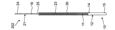









Classifications
-
- G—PHYSICS
- G01—MEASURING; TESTING
- G01R—MEASURING ELECTRIC VARIABLES; MEASURING MAGNETIC VARIABLES
- G01R1/00—Details of instruments or arrangements of the types included in groups G01R5/00 - G01R13/00 and G01R31/00
- G01R1/02—General constructional details
- G01R1/06—Measuring leads; Measuring probes
- G01R1/067—Measuring probes
Definitions
- the present invention relates to a probe pin and a probe unit including the probe pin.
- This conventional probe pin includes a cylindrical sleeve, a connection terminal provided at one end of the sleeve, a contact pin that slides in the sleeve, a shape memory alloy member that connects the connection terminal and the contact pin, a sleeve And a coil spring disposed between the other end and the contact pin.
- the conventional probe pin may be used as a probe unit together with a receptacle.
- conventional probe units there are those in which a receptacle and a probe pin are fitted to ensure conduction between the receptacle and the probe pin.
- an object of the present invention is to provide a probe pin for a receptacle with high contact reliability and a probe unit including the same.
- a probe pin includes a coil spring that expands and contracts along a center line, a first insertion portion that is inserted from one end of the coil spring along the center line, and the coil.
- a conductive first plunger having a first contact portion provided with a support portion for supporting a spring, and inserted along the center line from the other end of the coil spring, and slides on the first insertion portion.
- a conductive second plunger having a second insertion part movably connected and a second contact part provided with a support part for supporting the coil spring. At least one of the first and second contact portions is provided with an elastic spring portion protruding from the contact portion.
- the elastic spring portion protruding from the contact portion is provided on at least one of the first and second contact portions. For this reason, for example, when the probe pin is inserted into the receptacle, the elastic spring portion presses the inner peripheral surface of the receptacle, so that there is no rattling between the receptacle and the probe pin, and the contact is always made at a predetermined contact pressure. be able to. Thereby, the contact stability between the receptacle and the probe pin can be enhanced.
- the elastic spring portion may be provided in the first and second contact portions.
- the elastic spring portion is provided in each of the first and second contact portions, for example, when the probe pin is inserted into the receptacle, the elasticity of the first and second contact portions is determined.
- the spring portion presses the inner peripheral surface of the receptacle. For this reason, rattling of the probe pin can be reliably prevented and contact stability between the receptacle and the probe pin can be improved.
- the first and second plungers may be formed by electroforming.
- the first and second plungers can be formed with high accuracy. For this reason, the contact stability between the receptacle and the probe pin can be enhanced.
- the probe unit according to the present invention includes the probe pin and a receptacle having a storage portion in which the probe pin is stored and the elastic spring portion is disposed.
- the contact stability can be easily increased by the probe pin.
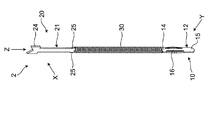
- FIG. 3 is an X arrow view of the probe pin of FIG. 2.
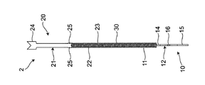
- FIG. 3 is a Y arrow view of the probe pin of FIG. 2.
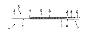
- FIG. 3 is a Z arrow view of the probe pin of FIG. 2.
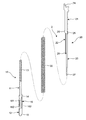
- FIG. 3 is an exploded perspective view of the probe pin of FIG. 2. It is a longitudinal cross-sectional view of the probe unit of FIG. It is the elements on larger scale of the longitudinal cross-sectional view of FIG. It is a perspective view of the probe pin of 2nd Embodiment of this invention.
- FIG. 3 is an X arrow view of the probe pin of FIG. 2.
- FIG. 3 is a Y arrow view of the probe pin of FIG. 2.
- FIG. 3 is a Z arrow view of the probe pin of FIG. 2.
- FIG. 3 is an exploded perspective view of the probe pin of FIG. 2.
- It is a longitudinal cross-sectional view of the probe unit of FIG. It is the elements on larger scale of the longitudinal cross-sectional view of FIG.
- FIG. 10 is an X arrow view of the probe pin of FIG. 9.
- FIG. 10 is a Y arrow view of the probe pin of FIG. 9.
- FIG. 10 is a Z arrow view of the probe pin of FIG. 9.
- FIG. 10 is an exploded perspective view of the probe pin of FIG. 9. It is a perspective view of the probe pin of 3rd Embodiment of this invention. It is a X arrow directional view of the probe pin of FIG.
- FIG. 15 is a Y arrow view of the probe pin of FIG. 14.
- FIG. 15 is a Z arrow view of the probe pin of FIG. 14.
- FIG. 15 is an exploded perspective view of the probe pin of FIG. 14. It is a perspective view of the probe pin of 4th Embodiment of this invention.
- FIG. 10 is an X arrow view of the probe pin of FIG. 9.
- FIG. 10 is a Y arrow view of the probe pin of FIG. 9.
- FIG. 10 is a Z arrow view of the
- FIG. 20 is an X arrow view of the probe pin of FIG. 19.
- FIG. 20 is a Y arrow view of the probe pin of FIG. 19.
- FIG. 20 is a Z arrow view of the probe pin of FIG. 19.
- FIG. 20 is an exploded perspective view of the probe pin of FIG. 19. It is a perspective view of the probe pin of 5th Embodiment of this invention.
- FIG. 26 is an X arrow view of the probe pin of FIG. 25. It is a Y arrow view of the probe pin of FIG. It is a Z arrow view of the probe pin of FIG.
- FIG. 26 is an exploded perspective view of the probe pin of FIG. 25. It is a perspective view of the probe pin of 6th Embodiment of this invention.
- FIG. 25 It is a perspective view of the probe pin of 6th Embodiment of this invention.
- FIG. 30 is an X arrow view of the probe pin of FIG. 29.
- FIG. 30 is a Y arrow view of the probe pin of FIG. 29.
- FIG. 30 is a Z arrow view of the probe pin of FIG. 29.
- FIG. 30 is an exploded perspective view of the probe pin of FIG. 29. It is a perspective view of the probe pin of 7th Embodiment of this invention.
- FIG. 35 is a view taken along the arrow X of the probe pin of FIG. 34.
- FIG. 35 is a Y arrow view of the probe pin of FIG. 34.
- FIG. 35 is a Z arrow view of the probe pin of FIG. 34. It is a disassembled perspective view of the probe pin of FIG.
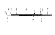
- the probe unit 100 including the probe pin according to the first embodiment of the present invention includes a receptacle 1 and a probe pin 2 inserted into the receptacle 1.
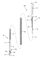
- the probe pin 2 includes a first plunger 10, a second plunger 20, and a coil spring 30, as shown in FIGS.
- Each of the first and second plungers 10 and 20 has conductivity, and is formed by, for example, an electroforming method.
- the first plunger 10 has a rectangular plate shape having substantially the same thickness, and is a sandwiched portion 11 as an example of a first insertion portion and a contact portion as an example of a first contact portion. 12.
- board thickness direction of the 1st plunger 10 be a main surface, and let a surface parallel to the plate
- the sandwiched portion 11 has a rectangular shape when viewed from the main surface, and a guide groove 13 penetrating the sandwiched portion 11 is provided on the leading end side (upper side in FIG. 6) of the major surface.
- the guide groove 13 has a rectangular shape extending in the longitudinal direction of the sandwiched portion 11 and has a width larger than the plate thickness of the second plunger 20.
- the contact portion 12 has a substantially rectangular shape when viewed from the main surface and has a width larger than that of the sandwiched portion 11.
- the base portion 14 is an example of a support portion continuous to the sandwiched portion 11, and a distal end having a free end formed in an arc shape. It is comprised by the part 15, and the elastic spring part 16 provided between the base 14 and the front-end
- the elastic spring portion 16 includes a central connecting portion 161 and an elastic bending portion 162 provided on both sides of the central connecting portion 161 with a gap therebetween.
- the central connecting portion 161 has a rectangular shape in main surface view and is connected to the base portion 14 and the distal end portion 15.
- the elastic bending portion 162 has a main surface arc shape protruding from the side surface of the contact portion 12, and is connected to both ends of the base portion 14 and the distal end portion 15 in the width direction.
- the 1st plunger 10 is formed symmetrically with respect to the center line of the width direction of a main surface.
- the second plunger 20 has a linearly extending plate shape having substantially the same thickness, and a contact portion 21 as an example of a second contact portion and a base end of the contact portion 21 (see FIG. 6 and the first and second elastic pieces 22 and 23 as an example of the second insertion portion provided at the lower end of the second insertion portion.
- board thickness direction of the 2nd plunger 20 be a main surface, and let a surface parallel to the plate
- the contact portion 21 has a substantially rectangular shape when viewed from the main surface, and a contact portion 24 having a V-shape when viewed from the main surface is provided at the tip (the upper end in FIG. 6).
- the contact portion 24 has a larger width than the contact portion 21.
- a coil spring support portion 25 which is an example of a support portion, is provided at the base end (lower end in FIG. 6) of the contact portion 21 so as to protrude from the side surface of the contact portion 21.
- the first and second elastic pieces 22 and 23 have a rectangular shape when viewed from the main surface, and the contact portion 21 also has a small width.
- the first and second elastic pieces 22 and 23 are respectively disposed at both ends in the width direction of the base end of the contact portion 21, and extend substantially parallel to each other at intervals along the longitudinal direction of the contact portion 21. .
- a gap larger than the plate thickness of the first plunger 10 is formed between the first and second elastic pieces 22 and 23. That is, in the first and second elastic pieces 22 and 23, the distance between the inner side surfaces which are the opposite side surfaces is larger than the plate thickness of the first plunger 10, and the distance between the outer side surfaces which are the side surfaces opposite to the inner side surface is increased. The distance is provided so as to be approximately equal to the width of the contact portion 21.
- the first and second elastic pieces 22 and 23 have different lengths, and the first elastic piece 22 is shorter than the second elastic piece 23.
- a guide projection 26 is provided at the tip of the inner surface of the first elastic piece 22 so as to protrude toward the second elastic piece 23. Further, a contact protrusion 27 is provided at the tip of the inner side surface of the second elastic piece 23 so as to protrude toward the first elastic piece 22. The contact protrusion 27 is arranged so as to always contact the sandwiched portion 11 of the first plunger 10 with the guide protrusion 26 of the first elastic piece 22 fitted in the guide groove 13 of the first plunger 10. ing.
- the coil spring 30 is made of, for example, carbon steel or stainless steel, and is formed to expand and contract along its center line. As shown in FIGS. 2 to 5, the coil spring 30 has an inner diameter that is slightly larger than the width of the sandwiched portion 11 of the first plunger 10 and the width of the contact portion 21 of the second plunger 20. . Further, the coil spring 30 has substantially the same outer diameter as the width of the contact portion 12 of the first plunger 10 and the width of the portion of the second plunger 20 where the coil spring support portion 25 is provided. .
- both ends of the coil spring 30 are connected to the base portion 14 of the first plunger 10 and the first plunger 10. 2
- the spring length is adjusted so that it is supported by the coil spring support portion 25 of the plunger 20 and is always compressed.
- the receptacle 1 is made of a conductive material, and is composed of first and second housings 41 and 42 having an elongated cylindrical shape as shown in FIG.
- the first and second housings 41 and 42 have different sizes of diameters, are arranged in a straight line, and are integrated.
- a storage portion 43 that can store the probe pin 2 is provided inside the first housing 41.
- the storage portion 43 is provided with a circular opening 44 that opens at one end of the receptacle 1, and the elastic spring portion 16 of the probe pin 2 is disposed therein.
- the storage portion 43 has a diameter larger than the width of the sandwiched portion 11 of the first plunger 10 of the probe pin 2 and smaller than the width of the elastic spring portion 16 portion.
- the probe pin 2 is assembled.
- the first plunger 10 is inserted from one end side of the coil spring 30 along the center line of the coil spring 30, while the second plunger 20 is inserted from the other end side of the coil spring 30 along the center line of the coil spring 30.
- the first plunger 10 is inserted into the coil spring 30 from the sandwiched portion 11 side
- the second plunger 20 is inserted into the coil spring 30 from the first and second elastic pieces 22 and 23 side.
- the 1st, 2nd plungers 10 and 20 are inserted so that the main surface of the 1st plunger 10 and the main surface of the 2nd plunger 20 may orthogonally cross, as shown in FIG.
- the contact protrusion 27 of the second elastic piece 23 comes into contact with the sandwiched portion 11 of the first plunger 10. Then, the second elastic piece 23 is elastically deformed in a direction perpendicular to the insertion direction of the probe pin 2, and the contact protrusion 27 of the second elastic piece 23 is inserted into the guide groove 13 of the first plunger 10.
- the guide protrusion of the first elastic piece 22. 26 is in contact with the sandwiched portion 11 of the first plunger 10. Then, the first elastic piece 22 is elastically deformed in a direction perpendicular to the insertion direction of the probe pin 2, and the sandwiched portion 11 is held between the first elastic piece 22 and the second elastic piece 23.
- the contact protrusion 27 of the second elastic piece 23 comes into contact with the proximal end side of the sandwiched portion 11 (below the guide groove 64 in FIG. 6). Further, the guide protrusion 26 of the first elastic piece 22 is inserted into the guide groove 13 and the first and second plungers 10 and 20 are connected. Thereby, the assembly of the probe pin 2 is completed.
- the probe pin 2 When the assembly of the probe pin 2 is completed, the probe pin 2 is inserted into the receptacle 1 from the first plunger 10 side.
- the elastic bending portion 162 of the elastic spring portion 16 of the probe pin 2 comes into contact with the end surface on the opening 44 side of the receptacle 1 and is pushed into the receptacle 1 while being elastically deformed. It is. Therefore, as shown in FIG. 8, the probe pin 2 is inserted into the receptacle while the elastic spring portion 16 is inserted into the receptacle 1 and then the inner surface of the storage portion 43 is pressed by the elastic bending portion 162. Is done.
- the probe pin 2 is inserted into the receptacle 1 until the distal end portion 15 of the first plunger 10 and the bottom surface 45 of the storage portion 43 come into contact, and the assembly process of the probe unit 100 is completed. .
- the probe pin 2 in the initial state housed in the receptacle 1 partially protrudes from the opening 44 of the receptacle 1 including the contact portion 24 of the second plunger 20.
- the clamped portion 11 of the first plunger 10 and the contact protrusion 27 of the second plunger 20 are in contact with each other, and the elastic bending portion 162 of the elastic spring portion 16 of the first plunger 10 is in contact.
- the inner peripheral surface of the receptacle 1 is pressed. For this reason, the probe pins 2 are always in contact with the receptacle 1 without rattling, and are electrically connected to each other.
- the elastic bending portion 162 of the elastic spring portion 16 of the first plunger 10 presses the inner peripheral surface of the receptacle 1. For this reason, no rattling occurs between the receptacle 1 and the probe pin 2, and the contact is always made at a predetermined contact pressure. For this reason, the contact stability between the receptacle 1 and the probe pin 2 can be improved.
- the receptacle 1 and the probe pin 2 are brought into contact with each other by pressing the inner peripheral surface of the receptacle 1 with the elastic spring portion 16. For this reason, even if the gap between the receptacle 1 and the probe pin 2 widens due to the replacement of the probe pin 2, the receptacle 1 and the probe pin 2 can be reliably brought into contact with each other.
- the contact protrusion 27 of the second elastic piece 23 of the second plunger 20 is the base end side of the sandwiched portion 11 of the first plunger 10 (below the guide groove 64 of FIG. 6). Always in contact with. For this reason, the contact stability between the 1st, 2nd plungers 10 and 20 can be improved.
- the guide protrusion 26 of the second plunger 20 slides along the guide groove 13 of the first plunger 10. Thereby, the contact position where the to-be-clamped part 11 of the 1st plunger 10 and the contact protrusion 27 of the 2nd plunger 20 contact can be detected correctly.
- (Second Embodiment) 9 to 13 are diagrams showing the probe pin 102 of the second embodiment.
- the same parts as those in the first embodiment are denoted by the same reference numerals, and the description thereof is omitted. Differences from the first embodiment will be described.
- the probe pin 102 of the second embodiment includes a contact portion 24 of the contact portion 21 of the second plunger 20 in addition to the elastic spring portion 16 provided on the contact portion 12 of the first plunger 10. It differs from the probe pin 2 of the first embodiment in that an elastic spring portion 16 is provided between the coil spring support portion 25 and the coil spring support portion 25.
- the first plunger not only the first plunger but also the second plunger is provided with an elastic spring portion, so that rattling of the probe pin when inserted into the receptacle can be reliably prevented, and the receptacle and the probe pin are reliably in contact with each other. Can be made.
- (Third embodiment) 14 to 18 are diagrams showing a probe pin 202 of the third embodiment.
- the same parts as those in the first embodiment are denoted by the same reference numerals, and the description thereof will be omitted. Differences from the first embodiment will be described.
- the probe pin 202 of the third embodiment is provided with the contact portion 24 of the contact portion 21 of the second plunger 20 without providing the elastic spring portion 16 on the contact portion 12 of the first plunger 10.
- the probe spring 2 is different from the probe pin 2 of the first embodiment in that the elastic spring portion 16 is provided between the coil spring support portion 25 and the coil spring support portion 25.
- the elastic spring portion may be provided on at least one of the first and second plungers.
- FIGS. 19 to 23 are diagrams showing a probe pin 302 of the fourth embodiment.
- the same parts as those in the first embodiment are denoted by the same reference numerals, and the description thereof is omitted. Differences from the first embodiment will be described.
- the probe pin 302 according to the fourth embodiment is different in that the elastic spring part 116 having a cantilevered elastic bending part 163 is provided on the contact part 12 of the first plunger 10. It differs from the probe pin 2 of one embodiment.
- the shape of the elastic spring portion can be appropriately changed according to the design of the probe pin and the like, and the degree of freedom in designing the probe pin can be expanded.
- (Fifth embodiment) 24 to 28 are views showing a probe pin 402 of the fifth embodiment.
- the same parts as those in the first embodiment are denoted by the same reference numerals, and the description thereof is omitted. Differences from the first embodiment will be described.
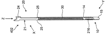
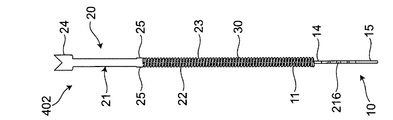
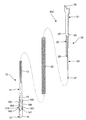
- the probe pin 402 of the fifth embodiment is different from that of the first embodiment in that an elastic spring portion 216 having an elastic bending portion 164 is provided on the contact portion 12 of the first plunger 10. Different from the probe pin 2.
- the elastic bending portion 164 is provided with two protrusions 165 protruding from the outer side surface of the contact portion 12 in the width direction.
- the protrusions 165 are arranged symmetrically with respect to a straight line connecting the longitudinal centers of the two elastic bending portions 164.
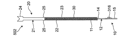
- (Sixth embodiment) 29 to 33 are diagrams showing a probe pin 502 of the sixth embodiment.
- the same parts as those in the first embodiment are denoted by the same reference numerals, description thereof is omitted, and differences from the first embodiment will be described.
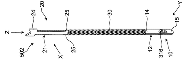
- the probe pin 502 of the sixth embodiment is different from the probe pin 2 of the first embodiment in that an elastic spring portion 316 is provided on the contact portion 12 of the first plunger 10. Yes.
- the elastic spring portion 316 includes a rectangular cut hole 166 formed at the center of the main surface of the contact portion 12 and an elastic arm connected to one short side of the cut hole 166 and bent in the thickness direction. Part 167. Further, the distal end of the elastic arm portion 167 is bent toward the main surface of the contact portion 12.
- the elastic spring portion is not limited to the case where it protrudes from the side surface of the contact portion, but can be provided so as to protrude from the main surface of the contact portion. Thereby, the freedom degree of design of a probe pin can be expanded.
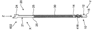
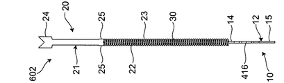
- (Seventh embodiment) 34 to 38 are diagrams showing a probe pin 602 of the seventh embodiment.
- the same parts as those in the first embodiment are denoted by the same reference numerals, description thereof is omitted, and differences from the first embodiment will be described.
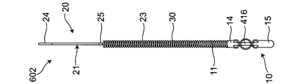
- the probe pin 602 of the seventh embodiment is the first in that an elastic spring part 416 having a bellows-like elastic curved part 168 is provided on the contact part 12 of the first plunger 10. This is different from the probe pin 2 of the embodiment.
- the shape of the elastic spring portion can be appropriately changed according to the design of the probe pin and the like, and the degree of freedom in designing the probe pin can be expanded.
- the shape of the free end of the distal end portion 15 of the first plunger 10 is not limited to an arc shape, and can be appropriately selected according to the design of the probe pin, such as a triangle or a quadrangle.
- the guide protrusion 26 of the first elastic piece 22 of the second plunger 20 may be any one as long as it can be inserted and fitted into the guide groove 13 of the first plunger 10 and can slide and move within the guide groove 13. Can be selected as appropriate.
- the shape or size of the contact protrusion 27 of the second elastic piece 23 of the second plunger 20 can be appropriately selected according to the design. By changing the shape or the like of the contact protrusion 27, the urging force of the second elastic piece 23 against the sandwiched portion 11 of the first plunger 10 can be adjusted.
- the plate thicknesses of the first and second plungers 10 and 20 are not limited to the same case, and may have different plate thicknesses depending on the part.
- the first and second plungers 10 and 20 can be subjected to surface treatment such as plating and coating according to the design.
- the first and second plungers 10 and 20 are not limited to electroforming, and any method can be used as long as the probe pins 2, 102, 202, 302, 402, 502, and 602 of the first to seventh embodiments can be formed. Can be selected.
- the sandwiched portion 11 having the guide groove 13 is provided in the first plunger 10 and the first and second elastic pieces 22 and 23 are provided in the second plunger 20, this is not restrictive.
- the first plunger may be provided with first and second elastic pieces
- the second plunger may be provided with a sandwiched portion having a guide groove.
- the first and second plungers 10 and 20 can adopt any configuration as long as they are slidable and conductive when inserted from both ends of the coil spring 30, respectively.
- the probe pins and probe units according to the present invention can be applied to inspection units such as semiconductor integrated circuits and semiconductor devices.
Landscapes
- Physics & Mathematics (AREA)
- General Physics & Mathematics (AREA)
- Measuring Leads Or Probes (AREA)
- Testing Or Measuring Of Semiconductors Or The Like (AREA)
Abstract
プローブピン(2)が、中心線に沿って伸縮するコイルばね(30)と、コイルばね(30)の一端から中心線に沿って挿入された被挟持部(11)と、コイルばね(30)を支持する基部(14)が設けられた接触部(12)とを有する導電性の第1プランジャ(10)と、コイルばね(30)の他端から中心線に沿って挿入され、被挟持部(11)とスライド移動可能に連結された第1,第2弾性片(22,23)と、コイルばね(30)を支持するコイルばね支持部(25)が設けられた接触部(21)とを有する導電性の第2プランジャ(20)と、を備える。第1プランジャ(10)の接触部(12)に、この接触部(12)からせり出した弾性ばね部(16)を設けた。
Description
本発明は、プローブピン、および、このプローブピンを備えたプローブユニットに関する。
従来、プローブピンとしては、特許文献1に記載されたものがある。この従来のプローブピンは、円筒形状のスリーブと、スリーブの一端部に設けられた接続端子と、スリーブ内をスライド移動するコンタクトピンと、接続端子とコンタクトピンとを連結する形状記憶合金部材と、スリーブの他端とコンタクトピンとの間に配置されたコイルばねとを備えている。
ところで、従来の前記プローブピンは、リセプタクルと共にプローブユニットとして用いる場合がある。このような従来のプローブユニットの中には、リセプタクルとプローブピンとを嵌合させて、リセプタクルとプローブピンとの間の導通を確保しているものがある。
しかし、前記プローブユニットでは、プローブピンを交換する毎にリセプタクルの内周面が削れてしまい、リセプタクルとプローブピンとの間に隙間が形成される場合があった。この場合、プローブピンとリセプタクルとの間の接触が不安定になり、接触信頼性が低下してしまうという問題があった。
本発明は、前述の問題に鑑み、接触信頼性の高いリセプタクル用プローブピン、および、これを備えたプローブユニットを提供することを課題とする。
本発明に係るプローブピンは、前記課題を解決すべく、中心線に沿って伸縮するコイルばねと、前記コイルばねの一端から前記中心線に沿って挿入された第1の挿入部と、前記コイルばねを支持する支持部が設けられた第1の接触部とを有する導電性の第1プランジャと、前記コイルばねの他端から前記中心線に沿って挿入され、前記第1の挿入部にスライド移動可能に連結された第2の挿入部と、前記コイルばねを支持する支持部が設けられた第2の接触部とを有する導電性の第2プランジャと、を備える。第1または第2の前記接触部の少なくともいずれか一方に、前記接触部からせり出した弾性ばね部を設けた。
本発明のプローブピンによれば、第1または第2の接触部の少なくともいずれか一方に、接触部からせり出した弾性ばね部を設けている。このため、例えば、このプローブピンをリセプタクルに挿入すると、弾性ばね部がリセプタクルの内周面を押圧するので、リセプタクルとプローブピンとの間にがたつきが生じず、常に所定の接触圧で接触させることができる。これにより、リセプタクルとプローブピンとの間の接触安定性を高めることができる。
本発明の実施形態としては、前記弾性ばね部が、第1および第2の前記接触部に設けられた構成としてもよい。
本実施形態によれば、第1および第2の接触部の各々に弾性ばね部を設けているので、例えば、このプローブピンをリセプタクルに挿入したときに、第1,第2の接触部の弾性ばね部がリセプタクルの内周面を押圧する。このため、プローブピンのがたつきを確実に防止できると共に、リセプタクルとプローブピンとの間の接触安定性を高めることができる。
本発明の実施形態としては、前記第1,第2プランジャが電鋳法で形成されている構成としてもよい。
本実施形態によれば、第1,第2プランジャを高い精度で形成できる。このため、リセプタクルとプローブピンとの間の接触安定性を高めることができる。
本発明に係るプローブユニットは、前記プローブピンと、このプローブピンが収納され、かつ、前記弾性ばね部が配置される収納部を有するリセプタクルとを備えた。
本発明のプローブユニットによれば、前記プローブピンによって、接触安定性を容易に高めることができる。
以下、添付図面を参照して本発明の実施形態を説明する。なお、以下の説明では、図面に表された構成を説明するうえで、「上」、「下」、「左」、「右」等の方向を示す用語、及びそれらを含む別の用語を使用するが、それらの用語を使用する目的は図面を通じて実施形態の理解を容易にするためである。したがって、それらの用語は本発明の実施形態が実際に使用されるときの方向を示すものとは限らないし、それらの用語によって特許請求の範囲に記載された発明の技術的範囲が限定的に解釈されるべきでない。
(第1実施形態)
本発明の第1実施形態のプローブピンを備えたプローブユニット100は、図1に示すように、リセプタクル1と、このリセプタクル1に挿入されたプローブピン2とを備えている。
本発明の第1実施形態のプローブピンを備えたプローブユニット100は、図1に示すように、リセプタクル1と、このリセプタクル1に挿入されたプローブピン2とを備えている。
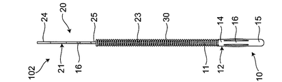
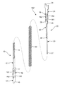
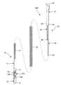
プローブピン2は、図2~図6に示すように、第1プランジャ10と、第2プランジャ20と、コイルばね30とで構成されている。第1,第2プランジャ10,20は、各々導電性を有しており、例えば電鋳法で形成されている。
第1プランジャ10は、図6に示すように、略同一の板厚を有する矩形の板形状で、第1の挿入部の一例の被挟持部11と、第1の接触部の一例の接触部12とで構成されている。なお、第1プランジャ10の板厚方向に直交する面を主要面とし、この主要面に直交する板厚方向に平行な面を側面とする。
被挟持部11は、主要面視矩形状を有し、その主要面の先端側(図6の上側)に、被挟持部11を貫通するガイド溝13が設けられている。このガイド溝13は、被挟持部11の長手方向に延びる矩形状で、第2プランジャ20の板厚よりも大きい幅を有している。
接触部12は、被挟持部11よりも大きい幅を有する主要面視略矩形状で、被挟持部11に連続する支持部の一例の基部14と、円弧状に形成された自由端を有する先端部15と、基部14と先端部15との間に設けられた弾性ばね部16とで構成されている。
弾性ばね部16は、中央連結部161と、この中央連結部161の両側に隙間を挟んで設けられた弾性湾曲部162とで構成されている。中央連結部161は、主要面視矩形状を有し、基部14と先端部15とに連結されている。弾性湾曲部162は、接触部12の側面からせり出した主要面視円弧形状を有し、基部14および先端部15の幅方向の両端にそれぞれ連結されている。
なお、第1プランジャ10は、主要面の幅方向の中心線に対して、対称に形成されている。
第2プランジャ20は、図6に示すように、略同一の板厚を有する直線状に延びる板形状で、第2の接触部の一例の接触部21と、この接触部21の基端(図6の下端)に設けられた第2の挿入部の一例の第1,第2弾性片22,23とで構成されている。なお、第2プランジャ20の板厚方向に直交する面を主要面とし、この主要面に直交する板厚方向に平行な面を側面とする。
接触部21は、主要面視略矩形状を有し、その先端(図6の上端)には、主要面視V字形状を有する接点部24が設けられている。この接点部24は、接触部21よりも大きい幅を有している。また、接触部21の基端(図6の下端)には、支持部の一例のコイルばね支持部25が、接触部21の側面から突出するように設けられている。
第1,第2弾性片22,23は、主要面視矩形状で、接触部21も小さい幅をそれぞれ有している。この第1,第2弾性片22,23は、接触部21の基端の幅方向の両端にそれぞれ配置され、接触部21の長手方向に沿って、間隔を空けて互いに略平行に延びている。第1,第2弾性片22,23の間には、第1プランジャ10の板厚よりも大きい隙間が形成されている。すなわち、第1,第2弾性片22,23は、向かい合う側面である内側面間の距離が、第1プランジャ10の板厚よりも大きくなり、内側面の反対側の側面である外側面間の距離が、接触部21の幅に略等しくなるように設けられている。また、第1,第2弾性片22,23は、長さが異なっており、第1弾性片22が第2弾性片23よりも短くなっている。
第1弾性片22の内側面の先端には、ガイド突起26が第2弾性片23に向かって突出するように設けられている。また、第2弾性片23の内側面の先端には、接触突起27が第1弾性片22に向かって突設されている。この接触突起27は、第1プランジャ10のガイド溝13に第1弾性片22のガイド突起26を嵌合した状態で、第1プランジャ10の被挟持部11に対して常に接触するように配置されている。
コイルばね30は、例えば、炭素鋼あるいはステンレス鋼からなり、その中心線に沿って伸縮するように形成されている。このコイルばね30は、図2~図5に示すように、第1プランジャ10の被挟持部11の幅、および、第2プランジャ20の接触部21の幅よりもやや大きい内径を有している。また、コイルばね30は、第1プランジャ10の接触部12の幅、および、第2プランジャ20のコイルばね支持部25が設けられている部分の幅と、略同一の外径を有している。
なお、コイルばね30は、図2~図5に示す状態、すなわち、第1プランジャ10と第2プランジャ20とが互いに組み合わされた状態では、その両端が、第1プランジャ10の基部14と、第2プランジャ20のコイルばね支持部25とで支持され、常時圧縮されるようにバネ長が調整されている。
リセプタクル1は、導電性の材料で形成され、図7に示すように、細長い円筒形状を有する第1,第2ハウジング41,42で構成されている。第1,第2ハウジング41,42は、それぞれ、異なる大きさの径を有しており、一直線に並ぶように配置され、一体化されている。また、第1ハウジング41の内部には、プローブピン2を収納可能な収納部43が設けられている。この収納部43には、リセプタクル1の一端に開口する円形の開口部44が設けられ、プローブピン2の弾性ばね部16が配置されるようになっている。
なお、収納部43は、プローブピン2の第1プランジャ10の被挟持部11の幅よりも大きく、弾性ばね部16部分の幅よりも小さい径を有している。
次に、第1実施形態のプローブピン2を備えるプローブユニット100の組立工程について説明する。
最初に、プローブピン2を組み立てる。まず、コイルばね30の一端側からコイルばね30の中心線に沿って第1プランジャ10を挿入する一方、コイルばね30の他端側からコイルばね30の中心線に沿って第2プランジャ20を挿入する。このとき、第1プランジャ10は、被挟持部11側からコイルばね30の内部に挿入され、第2プランジャ20は、第1,第2弾性片22,23側からコイルばね30の内部に挿入される。また、第1,第2プランジャ10,20は、図5に示すように、第1プランジャ10の主要面と第2プランジャ20の主要面とが直交するように、挿入される。
第2プランジャ20をコイルばね30の内部に挿入していくと、第2弾性片23の接触突起27が第1プランジャ10の被挟持部11と接触する。そして、第2弾性片23がプローブピン2の挿入方向に直交する方向に弾性変形し、第2弾性片23の接触突起27が、第1プランジャ10のガイド溝13に挿入される。
第2弾性片23の接触突起27が、第1プランジャ10のガイド溝13に挿入された後、第2プランジャ20をコイルばね30の内部に挿入していくと、第1弾性片22のガイド突起26が第1プランジャ10の被挟持部11と接触する。そして、第1弾性片22がプローブピン2の挿入方向に直交する方向に弾性変形し、被挟持部11が第1弾性片22と第2弾性片23とで挟持される。
被挟持部11が第1弾性片22と第2弾性片23とで挟持された後、第2プランジャ20をコイルばね30の内部にさらに挿入していくと、第2弾性片23の接触突起27が、ガイド溝13の端部(図6の下端)と接触する。そして、第2弾性片23がプローブピン2の挿入方向に直交する方向に弾性変形し、接触突起27が被挟持部11の基端側(図6のガイド溝64の下側)と接触する。また、第1弾性片22のガイド突起26が、ガイド溝13に挿入され、第1,第2プランジャ10,20が連結される。これにより、プローブピン2の組み立てが完了する。
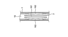
プローブピン2の組み立てが完了すると、このプローブピン2を第1プランジャ10側からリセプタクル1内に挿入する。プローブピン2をリセプタクル1内に挿入していくと、プローブピン2の弾性ばね部16の弾性湾曲部162がリセプタクル1の開口部44側の端面と接触し、弾性変形しながらリセプタクル1内に押し込まれる。このため、プローブピン2は、図8に示すように、弾性ばね部16がリセプタクル1内に挿入された後、弾性湾曲部162によって収納部43の内周面を押圧しながら、リセプタクル内に挿入される。
そして、図7に示すように、第1プランジャ10の先端部15と収納部43の底面45とが接触するまで、プローブピン2をリセプタクル1内に挿入し、プローブユニット100の組立工程が終了する。
続いて、リセプタクル1に収納されたプローブピン2の動作について説明する。
リセプタクル1に収納された初期状態のプローブピン2は、図7に示すように、第2プランジャ20の接点部24を含む一部がリセプタクル1の開口部44から突出している。
この初期状態のプローブピン2では、第1プランジャ10の被挟持部11と第2プランジャ20の接触突起27とが接触していると共に、第1プランジャ10の弾性ばね部16の弾性湾曲部162が、リセプタクル1の内周面を押圧している。このため、プローブピン2は、がたつくことなく、リセプタクル1と常に接触し、相互に導通している。
初期状態のプローブピン2の第2プランジャ20の接点部24に力を加え、第2プランジャ20をリセプタクル1内に向かって押し込むと、第2プランジャ20の第1弾性片22のガイド突起26が、第1プランジャ10のガイド溝13に沿ってスライド移動を開始する。このとき、コイルばね30は、第2プランジャ20のコイルばね支持部25を介して、第2プランジャ20に加えられた力が伝達され、次第に圧縮される。
第2プランジャ20をリセプタクル1内に向かってさらに押し込んでいくと、第2プランジャ10,20の接点部24がリセプタクル1内に完全に押し込まれ、第1,第2プランジャ10,20のスライド移動が停止する。
第1,第2プランジャ10,20が停止した後、第2プランジャ10,20の接点部24に加えられている力を解放すると、コイルばね30の復帰力によって、第2プランジャ20は、図7に示す初期状態に復帰する。
前記プローブユニット100では、第1プランジャ10の弾性ばね部16の弾性湾曲部162が、リセプタクル1の内周面を押圧している。このため、リセプタクル1とプローブピン2との間にがたつきが生じず、常に所定の接触圧で接触している。このため、リセプタクル1とプローブピン2との間の接触安定性を高めることができる。
また、弾性ばね部16でリセプタクル1の内周面を押圧することにより、リセプタクル1とプローブピン2とを接触させている。このため、仮に、プローブピン2の交換によって、リセプタクル1とプローブピン2との間の隙間が広がってしまったとしても、リセプタクル1とプローブピン2とを確実に接触させることができる。
第1実施形態のプローブピン2では、第2プランジャ20の第2弾性片23の接触突起27が、第1プランジャ10の被挟持部11の基端側(図6のガイド溝64の下側)と常に接触している。このため、第1,第2プランジャ10,20の間の接触安定性を高めることができる。
また、第2プランジャ20のガイド突起26は、第1プランジャ10のガイド溝13に沿ってスライド移動する。これにより、第1プランジャ10の被挟持部11と第2プランジャ20の接触突起27とが接触する接触位置を正確に検出できる。
(第2実施形態)
図9~図13は、第2実施形態のプローブピン102を示す図である。この第2実施形態では、第1実施形態と同一部分に同一参照番号を付して説明を省略し、第1実施形態と異なる点について説明する。
図9~図13は、第2実施形態のプローブピン102を示す図である。この第2実施形態では、第1実施形態と同一部分に同一参照番号を付して説明を省略し、第1実施形態と異なる点について説明する。
第2実施形態のプローブピン102は、図9~13に示すように、第1プランジャ10の接触部12に設けた弾性ばね部16に加え、第2プランジャ20の接触部21の接点部24とコイルばね支持部25との間にも弾性ばね部16を設けた点で、第1実施形態のプローブピン2と異なっている。
このように、第1プランジャだけでなく、第2プランジャにも弾性ばね部を設けることで、リセプタクルに挿入したときのプローブピンのがたつきを確実に防止でき、リセプタクルとプローブピンとを確実に接触させることができる。
(第3実施形態)
図14~図18は、第3実施形態のプローブピン202を示す図である。この第3実施形態では、第1実施形態と同一部分に同一参照番号を付して説明を省略し、第1実施形態と異なる点について説明する。
図14~図18は、第3実施形態のプローブピン202を示す図である。この第3実施形態では、第1実施形態と同一部分に同一参照番号を付して説明を省略し、第1実施形態と異なる点について説明する。
第3実施形態のプローブピン202は、図14~18に示すように、第1プランジャ10の接触部12に弾性ばね部16を設けずに、第2プランジャ20の接触部21の接点部24とコイルばね支持部25との間に弾性ばね部16を設けた点で、第1実施形態のプローブピン2と異なっている。
このように、弾性ばね部は、第1,第2プランジャの少なくともいずれか一方に設けてあればよい。これにより、プローブピンの設計の自由度を広げることができる。
(第4実施形態)
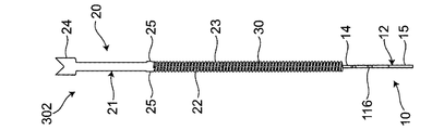
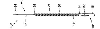
図19~図23は、第4実施形態のプローブピン302を示す図である。この第4実施形態では、第1実施形態と同一部分に同一参照番号を付して説明を省略し、第1実施形態と異なる点について説明する。
図19~図23は、第4実施形態のプローブピン302を示す図である。この第4実施形態では、第1実施形態と同一部分に同一参照番号を付して説明を省略し、第1実施形態と異なる点について説明する。
第4実施形態のプローブピン302は、図19~23に示すように、第1プランジャ10の接触部12に、片持ち状の弾性湾曲部163を有する弾性ばね部116を設けた点で、第1実施形態のプローブピン2と異なっている。
このように、弾性ばね部の形状は、プローブピンの設計等に応じて、適宜変更でき、プローブピンの設計の自由度を広げることができる。
(第5実施形態)
図24~図28は、第5実施形態のプローブピン402を示す図である。この第5実施形態では、第1実施形態と同一部分に同一参照番号を付して説明を省略し、第1実施形態と異なる点について説明する。
図24~図28は、第5実施形態のプローブピン402を示す図である。この第5実施形態では、第1実施形態と同一部分に同一参照番号を付して説明を省略し、第1実施形態と異なる点について説明する。
第5実施形態のプローブピン402は、図24~28に示すように、第1プランジャ10の接触部12に、弾性湾曲部164を有する弾性ばね部216を設けた点で、第1実施形態のプローブピン2と異なっている。この弾性湾曲部164には、接触部12の幅方向外側の側面から突出する2つの突起165が設けられている。突起165は、2つの弾性湾曲部164の長手方向の中心を結ぶ直線に対して対称に配置されている。
このように、弾性湾曲部に突起を設けることで、弾性ばね部によるリセプタクルの内周面への押圧力を調節できる。これにより、プローブピンの設計の自由度を広げることができる。
(第6実施形態)
図29~図33は、第6実施形態のプローブピン502を示す図である。この第6実施形態では、第1実施形態と同一部分に同一参照番号を付して説明を省略し、第1実施形態と異なる点について説明する。
図29~図33は、第6実施形態のプローブピン502を示す図である。この第6実施形態では、第1実施形態と同一部分に同一参照番号を付して説明を省略し、第1実施形態と異なる点について説明する。
第6実施形態のプローブピン502は、図29~33に示すように、第1プランジャ10の接触部12に、弾性ばね部316を設けた点で、第1実施形態のプローブピン2と異なっている。弾性ばね部316は、接触部12の主要面の中央に形成された矩形の切り込み孔部166と、この切り込み孔部166の一短辺に連結され、かつ、板厚方向に曲げ起こした弾性腕部167とで構成されている。また、この弾性腕部167の先端は、接触部12の主要面に向かって折り曲げられている。
このように、弾性ばね部は、接触部の側面からせり出す場合に限らず、接触部の主要面からせり出すように設けることもできる。これにより、プローブピンの設計の自由度を広げることができる。
(第7実施形態)
図34~図38は、第7実施形態のプローブピン602を示す図である。この第6実施形態では、第1実施形態と同一部分に同一参照番号を付して説明を省略し、第1実施形態と異なる点について説明する。
図34~図38は、第7実施形態のプローブピン602を示す図である。この第6実施形態では、第1実施形態と同一部分に同一参照番号を付して説明を省略し、第1実施形態と異なる点について説明する。
第7実施形態のプローブピン602は、図34~38に示すように、第1プランジャ10の接触部12に、ベローズ状の弾性湾曲部168を有する弾性ばね部416を設けた点で、第1実施形態のプローブピン2と異なっている。
このように、弾性ばね部の形状は、プローブピンの設計等に応じて、適宜変更でき、プローブピンの設計の自由度を広げることができる。
(その他の実施形態)
第1プランジャ10の先端部15の自由端の形状は、円弧状に限らず、三角形あるいは四角形等、プローブピンの設計等に応じて、適宜選択できる。
第1プランジャ10の先端部15の自由端の形状は、円弧状に限らず、三角形あるいは四角形等、プローブピンの設計等に応じて、適宜選択できる。
第2プランジャ20の第1弾性片22のガイド突起26は、第1プランジャ10のガイド溝13に挿入嵌合できると共に、ガイド溝13内をスライド移動できるものであればよく、形状,大きさ等は、適宜選択できる。
第2プランジャ20の第2弾性片23の接触突起27は、設計に応じて、形状あるいは大きさ等を適宜選択できる。接触突起27の形状等を変更することで、第2弾性片23の第1プランジャ10の被挟持部11に対する付勢力を調整することができる。
第1,第2プランジャ10,20の板厚は、同一の場合に限らず、部分により異なる板厚を有するようにしてもよい。
第1,第2プランジャ10,20は、設計に応じて、めっき,コーティング等の表面処理を行うこともできる。
第1,第2プランジャ10,20は、電鋳法に限らず、第1~第7実施形態のプローブピン2,102,202,302,402,502,602を形成できる方法であれば、任意に選択できる。
第1プランジャ10にガイド溝13を有する被挟持部11を設け、第2プランジャ20に第1,第2弾性片22,23を設けているが、これに限らない。例えば、第1プランジャに第1,第2弾性片を設け、第2プランジャにガイド溝を有する被挟持部を設けてもよい。
第1,第2プランジャ10,20は、コイルばね30の両端からそれぞれ挿入したときに、相互にスライド移動可能かつ導通可能であれば、任意の構成を採用できる。
第1~第7実施形態および変形例で述べた構成要素は、適宜、組み合わせてもよく、また、適宜、選択、置換、あるいは、削除してもよいことは、勿論である。
本発明に係るプローブピンおよびプローブユニットは、例えば、半導体集積回路および半導体デバイス等の検査ユニットに適用できる。
1 リセプタクル
2,102,202,302,402,502,602 プローブピン
10 第1プランジャ
11 被挟持部
12 接触部
13 ガイド溝
14 基部
15 先端部
16 弾性ばね部
20 第2プランジャ
21 接触部
22 第1弾性片
23 第2弾性片
24 接点部
25 コイルばね支持部
26 ガイド突起
27 接触突起
30 コイルばね
41 第1ハウジング
42 第2ハウジング
43 収納部
44 開口部
45 底面
161 中央連結部
162,163,164,168 弾性湾曲部
165 突起
166 切り込み孔部
167 弾性腕部
2,102,202,302,402,502,602 プローブピン
10 第1プランジャ
11 被挟持部
12 接触部
13 ガイド溝
14 基部
15 先端部
16 弾性ばね部
20 第2プランジャ
21 接触部
22 第1弾性片
23 第2弾性片
24 接点部
25 コイルばね支持部
26 ガイド突起
27 接触突起
30 コイルばね
41 第1ハウジング
42 第2ハウジング
43 収納部
44 開口部
45 底面
161 中央連結部
162,163,164,168 弾性湾曲部
165 突起
166 切り込み孔部
167 弾性腕部
Claims (4)
- 中心線に沿って伸縮するコイルばねと、
前記コイルばねの一端から前記中心線に沿って挿入された第1の挿入部と、前記コイルばねを支持する支持部が設けられた第1の接触部とを有する導電性の第1プランジャと、
前記コイルばねの他端から前記中心線に沿って挿入され、前記第1の挿入部にスライド移動可能に連結された第2の挿入部と、前記コイルばねを支持する支持部が設けられた第2の接触部とを有する導電性の第2プランジャと、
を備え、
第1または第2の前記接触部の少なくともいずれか一方に、前記接触部からせり出した弾性ばね部を設けた、プローブピン。 - 前記弾性ばね部が、第1および第2の前記接触部に設けられた、請求項1に記載のプローブピン。
- 前記第1,第2プランジャが電鋳法で形成されている、請求項1または2に記載のプローブピン。
- 請求項1から3のいずれか1項に記載のプローブピンと、このプローブピンが収納され、かつ、前記弾性ばね部が配置される収納部を有するリセプタクルとを備えたプローブユニット。
Priority Applications (1)
| Application Number | Priority Date | Filing Date | Title |
|---|---|---|---|
| CN201680010320.2A CN107250810A (zh) | 2015-03-13 | 2016-01-18 | 探针销及具备该探针销的探针组件 |
Applications Claiming Priority (2)
| Application Number | Priority Date | Filing Date | Title |
|---|---|---|---|
| JP2015050723A JP6531438B2 (ja) | 2015-03-13 | 2015-03-13 | プローブピン、および、これを備えたプローブユニット |
| JP2015-050723 | 2015-03-13 |
Publications (1)
| Publication Number | Publication Date |
|---|---|
| WO2016147691A1 true WO2016147691A1 (ja) | 2016-09-22 |
Family
ID=56919851
Family Applications (1)
| Application Number | Title | Priority Date | Filing Date |
|---|---|---|---|
| PCT/JP2016/051284 Ceased WO2016147691A1 (ja) | 2015-03-13 | 2016-01-18 | プローブピン、および、これを備えたプローブユニット |
Country Status (4)
| Country | Link |
|---|---|
| JP (1) | JP6531438B2 (ja) |
| CN (1) | CN107250810A (ja) |
| TW (1) | TWI585414B (ja) |
| WO (1) | WO2016147691A1 (ja) |
Cited By (3)
| Publication number | Priority date | Publication date | Assignee | Title |
|---|---|---|---|---|
| WO2017217042A1 (ja) * | 2016-06-17 | 2017-12-21 | オムロン株式会社 | プローブピン |
| CN111579834A (zh) * | 2020-05-18 | 2020-08-25 | 武汉精毅通电子技术有限公司 | 一种适用于大电流高速信号测试的探针及连接器 |
| US11387587B1 (en) | 2021-03-13 | 2022-07-12 | Plastronics Socket Partners, Ltd. | Self-retained slider contact pin |
Families Citing this family (13)
| Publication number | Priority date | Publication date | Assignee | Title |
|---|---|---|---|---|
| JP6988920B2 (ja) * | 2018-01-11 | 2022-01-05 | オムロン株式会社 | プローブピン、検査治具、検査ユニットおよび検査装置 |
| CN112005448B (zh) * | 2018-05-22 | 2022-09-23 | 欧姆龙株式会社 | 探针销 |
| TWI705248B (zh) * | 2019-02-15 | 2020-09-21 | 萬潤科技股份有限公司 | 探針驅動方法及裝置 |
| TWD234066S (zh) | 2023-11-07 | 2024-10-01 | 韓商惠康有限公司 (南韓) | Ic測試用探針 |
| TWD234070S (zh) | 2023-11-07 | 2024-10-01 | 韓商惠康有限公司 (南韓) | Ic測試用探針 |
| TWD234068S (zh) | 2023-11-07 | 2024-10-01 | 韓商惠康有限公司 (南韓) | Ic測試用探針 |
| TWD234064S (zh) | 2023-11-07 | 2024-10-01 | 韓商惠康有限公司 (南韓) | Ic測試用探針 |
| TWD234069S (zh) | 2023-11-07 | 2024-10-01 | 韓商惠康有限公司 (南韓) | Ic測試用探針 |
| TWD234067S (zh) | 2023-11-07 | 2024-10-01 | 韓商惠康有限公司 (南韓) | Ic測試用探針 |
| JP1821889S (ja) | 2024-01-18 | 2026-03-17 | 集積回路検査用プローブピン | |
| JP1821886S (ja) | 2024-01-18 | 2026-03-17 | 集積回路検査用プローブピン | |
| JP1831041S (ja) | 2024-08-21 | 2026-07-07 | 集積回路検査用プローブピン | |
| JP1831042S (ja) | 2024-08-21 | 2026-07-07 | 集積回路検査用プローブピン |
Citations (3)
| Publication number | Priority date | Publication date | Assignee | Title |
|---|---|---|---|---|
| JP2011232181A (ja) * | 2010-04-28 | 2011-11-17 | Japan Aviation Electronics Industry Ltd | プローブピン用コンタクト、プローブピンおよび電子デバイス用接続治具 |
| JP2013008467A (ja) * | 2011-06-22 | 2013-01-10 | Tyco Electronics Japan Kk | コンタクトおよびソケット |
| JP2015040734A (ja) * | 2013-08-21 | 2015-03-02 | オムロン株式会社 | プローブピン、および、これを用いた電子デバイス |
Family Cites Families (11)
| Publication number | Priority date | Publication date | Assignee | Title |
|---|---|---|---|---|
| JP4259405B2 (ja) * | 2004-06-15 | 2009-04-30 | 住友電装株式会社 | 基板用コネクタ |
| KR100584225B1 (ko) * | 2004-10-06 | 2006-05-29 | 황동원 | 전자장치용 콘택트 |
| JP4239029B2 (ja) * | 2006-05-24 | 2009-03-18 | 東神電気株式会社 | 螺旋状支持具及びそのコネクタ |
| KR100810044B1 (ko) * | 2006-08-10 | 2008-03-05 | 리노공업주식회사 | 검사용 탐침 장치 및 그 제조방법 |
| KR100769891B1 (ko) * | 2007-01-25 | 2007-10-24 | 리노공업주식회사 | 검사용 탐침 장치 및 이를 이용한 검사용 소켓 |
| JP5067790B2 (ja) * | 2007-04-27 | 2012-11-07 | センサータ テクノロジーズ マサチューセッツ インコーポレーテッド | プローブピンおよびそれを用いたソケット |
| JP5282540B2 (ja) * | 2008-11-21 | 2013-09-04 | 日立電線株式会社 | 雄雌接続構造 |
| CN102414925B (zh) * | 2009-07-03 | 2015-05-27 | 矢崎总业株式会社 | 阴端子 |
| JP2011096606A (ja) * | 2009-11-02 | 2011-05-12 | Smk Corp | ポゴピン式圧接型コネクタ |
| TWM390564U (en) * | 2010-03-18 | 2010-10-11 | Hon Hai Prec Ind Co Ltd | Electrical contact |
| US8373430B1 (en) * | 2012-05-06 | 2013-02-12 | Jerzy Roman Sochor | Low inductance contact probe with conductively coupled plungers |
-
2015
- 2015-03-13 JP JP2015050723A patent/JP6531438B2/ja active Active
-
2016
- 2016-01-18 WO PCT/JP2016/051284 patent/WO2016147691A1/ja not_active Ceased
- 2016-01-18 CN CN201680010320.2A patent/CN107250810A/zh active Pending
- 2016-03-07 TW TW105106838A patent/TWI585414B/zh not_active IP Right Cessation
Patent Citations (3)
| Publication number | Priority date | Publication date | Assignee | Title |
|---|---|---|---|---|
| JP2011232181A (ja) * | 2010-04-28 | 2011-11-17 | Japan Aviation Electronics Industry Ltd | プローブピン用コンタクト、プローブピンおよび電子デバイス用接続治具 |
| JP2013008467A (ja) * | 2011-06-22 | 2013-01-10 | Tyco Electronics Japan Kk | コンタクトおよびソケット |
| JP2015040734A (ja) * | 2013-08-21 | 2015-03-02 | オムロン株式会社 | プローブピン、および、これを用いた電子デバイス |
Cited By (3)
| Publication number | Priority date | Publication date | Assignee | Title |
|---|---|---|---|---|
| WO2017217042A1 (ja) * | 2016-06-17 | 2017-12-21 | オムロン株式会社 | プローブピン |
| CN111579834A (zh) * | 2020-05-18 | 2020-08-25 | 武汉精毅通电子技术有限公司 | 一种适用于大电流高速信号测试的探针及连接器 |
| US11387587B1 (en) | 2021-03-13 | 2022-07-12 | Plastronics Socket Partners, Ltd. | Self-retained slider contact pin |
Also Published As
| Publication number | Publication date |
|---|---|
| TWI585414B (zh) | 2017-06-01 |
| JP2016170096A (ja) | 2016-09-23 |
| JP6531438B2 (ja) | 2019-06-19 |
| TW201636619A (zh) | 2016-10-16 |
| CN107250810A (zh) | 2017-10-13 |
Similar Documents
| Publication | Publication Date | Title |
|---|---|---|
| JP6531438B2 (ja) | プローブピン、および、これを備えたプローブユニット | |
| JP5985447B2 (ja) | プローブピン、および、これを用いた電子デバイス | |
| JP6337633B2 (ja) | プローブピン | |
| CN102422170B (zh) | 擦拭引发型顺应式电接触 | |
| JP6442668B2 (ja) | プローブピンおよびicソケット | |
| JP6013731B2 (ja) | コンタクトプローブおよびその製造方法 | |
| JP6515516B2 (ja) | プローブピン、および、これを備えた電子デバイス | |
| US20100007365A1 (en) | Socket for double ended probe, double ended probe, and probe unit | |
| KR101769355B1 (ko) | 수직형 프로브핀 및 이를 구비한 프로브핀 조립체 | |
| TW201730566A (zh) | 探針以及使用該探針的檢查裝置 | |
| JP2018009790A (ja) | スプリングコンタクトおよびスプリングコンタクトを使用したソケット | |
| JP2016125943A (ja) | ケルビンプローブ、および、これを備えたケルビン検査ユニット | |
| JP2015169527A (ja) | プローブピン、および、これを用いた電子デバイス | |
| CN109417240A (zh) | 端子模块以及连接器 | |
| KR101910063B1 (ko) | 검사장치용 프로브 | |
| KR20180131312A (ko) | 수직형 프로브핀 및 이를 구비한 프로브핀 조립체 | |
| JP2018092813A (ja) | プローブピンおよびicソケット | |
| JP2015108608A (ja) | プローブピンおよびicソケット | |
| JP6582780B2 (ja) | プローブピンおよびこれを用いた検査治具 | |
| WO2018042931A1 (ja) | プローブピン | |
| JP6133706B2 (ja) | コネクタ構造 | |
| WO2015163160A1 (ja) | プローブピンおよびicソケット | |
| JP6141131B2 (ja) | 電気的接続装置 | |
| JP6132687B2 (ja) | 電気的接続装置 | |
| CN109792116A (zh) | 压接连接器 |
Legal Events
| Date | Code | Title | Description |
|---|---|---|---|
| 121 | Ep: the epo has been informed by wipo that ep was designated in this application |
Ref document number: 16764522 Country of ref document: EP Kind code of ref document: A1 |
|
| NENP | Non-entry into the national phase |
Ref country code: DE |
|
| 122 | Ep: pct application non-entry in european phase |
Ref document number: 16764522 Country of ref document: EP Kind code of ref document: A1 |