WO2016132959A1 - 偏光子、偏光板および画像表示装置 - Google Patents
偏光子、偏光板および画像表示装置 Download PDFInfo
- Publication number
- WO2016132959A1 WO2016132959A1 PCT/JP2016/053748 JP2016053748W WO2016132959A1 WO 2016132959 A1 WO2016132959 A1 WO 2016132959A1 JP 2016053748 W JP2016053748 W JP 2016053748W WO 2016132959 A1 WO2016132959 A1 WO 2016132959A1
- Authority
- WO
- WIPO (PCT)
- Prior art keywords
- polarizer
- iodine
- resin film
- low concentration
- solution
- Prior art date
- Legal status (The legal status is an assumption and is not a legal conclusion. Google has not performed a legal analysis and makes no representation as to the accuracy of the status listed.)
- Ceased
Links
Images
Classifications
-
- G—PHYSICS
- G02—OPTICS
- G02B—OPTICAL ELEMENTS, SYSTEMS OR APPARATUS
- G02B5/00—Optical elements other than lenses
- G02B5/30—Polarising elements
- G02B5/3025—Polarisers, i.e. arrangements capable of producing a definite output polarisation state from an unpolarised input state
- G02B5/3033—Polarisers, i.e. arrangements capable of producing a definite output polarisation state from an unpolarised input state in the form of a thin sheet or foil, e.g. Polaroid
- G02B5/3041—Polarisers, i.e. arrangements capable of producing a definite output polarisation state from an unpolarised input state in the form of a thin sheet or foil, e.g. Polaroid comprising multiple thin layers, e.g. multilayer stacks
- G02B5/305—Polarisers, i.e. arrangements capable of producing a definite output polarisation state from an unpolarised input state in the form of a thin sheet or foil, e.g. Polaroid comprising multiple thin layers, e.g. multilayer stacks including organic materials, e.g. polymeric layers
Definitions
- the present invention relates to a polarizer, a polarizing plate, and an image display device.
- Some image display devices such as mobile phones and notebook personal computers (PCs) are equipped with internal electronic components such as cameras.
- Various studies have been made for the purpose of improving the camera performance and the like of such an image display device (for example, Patent Documents 1 to 4).
- Patent Documents 1 to 4 For example, Patent Documents 1 to 4
- smartphones and touch panel type information processing devices further improvements in camera performance and the like are desired.
- polarizer having partially polarization performance.
- the present invention has been made to solve the above-described conventional problems, and a main object of the present invention is to provide a polarizer capable of realizing multi-function and high-performance of an electronic device such as an image display device. .
- the polarizer of the present invention has a thickness of 13 ⁇ m or less and is composed of a resin film containing iodine. In this resin film, a low-concentration portion having a lower iodine content than other parts is formed.
- part is 42.0% or more, and a polarization degree is 99.95% or more.
- the transmittance of the low concentration portion is 50% or more.
- the content of iodine in the low concentration part is 1.0% by weight or less.
- the low concentration portion is substantially circular with a diameter of 10 mm or less.
- the thickness of the resin film is 8 ⁇ m or less.
- the low density portion corresponds to a camera hole portion of an image display device to be mounted.
- the low concentration part is formed by bringing a basic solution into contact with the resin film containing iodine.
- the basic solution is a 1 wt% or more aqueous sodium hydroxide solution.
- a polarizing plate is provided.
- the polarizing plate of this invention has the said polarizer.
- an image display device is provided.
- the image display apparatus of this invention has the said polarizing plate.
- the manufacturing method of the said polarizer is provided.
- the method for producing a polarizer of the present invention includes a step of bringing a basic solution into contact with a resin film having a thickness of 13 ⁇ m or less and containing iodine.
- the temperature of the basic solution is 20 ° C. or higher.
- the acidic solution is brought into contact with the portion of the resin film that has been brought into contact with the basic solution.
- the resin film is a resin layer formed on a substrate. In one embodiment, the resin layer is a coating layer.
- the polarizer by forming the polarizer from a resin film having a thickness of 13 ⁇ m or less and containing iodine, a low concentration portion having a lower iodine content than other portions and having excellent surface smoothness is formed.
- the low density portion is made to correspond to the camera hole portion of the image display device, not only the transparency of the camera hole portion is ensured, but also the brightness and color at the time of shooting are optimized, and the image Distortion can be prevented and it can contribute to the improvement of the camera performance of the obtained image display apparatus.
- the present invention not only receiving electronic devices such as images and monitors (for example, camera devices having a photographing optical system), but also transmitting electronic devices such as LED lights and infrared sensors, and the naked eye. It is also possible to provide an image display device that ensures the transparency of light and the straightness of light.
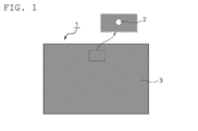
- FIG. 1 is a plan view of a polarizer according to one embodiment of the present invention.
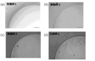
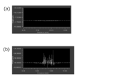
- FIG. It is an observation photograph by the optical microscope of the polarizer of an Example and a comparative example. It is a figure which shows the evaluation result of the surface smoothness of Example 1 and Comparative Example 1.
- FIG. 1 is a plan view of a polarizer according to one embodiment of the invention.
- the polarizer 1 is composed of a resin film containing a dichroic substance.
- a low concentration portion 2 having a relatively low content of the dichroic material is formed in the polarizer (resin film) 1.
- the polarizer 1 is formed with a low concentration portion 2 having a lower dichroic substance content than the other portions 3.
- the low density part can function as a non-polarizing part. According to such a configuration, cracks and delamination are mechanically compared (for example, by a method of mechanical engraving using a sculpture blade punching, a plotter, a water jet, or the like), compared to a case where a through hole is formed.
- the small circular low-density portion 2 is formed at the center of the upper end of the polarizer 1, but the number, arrangement, shape, size, etc. of the low-density portions can be appropriately designed. For example, it is designed according to the position, shape, size, etc. of the camera hole part of the mounted image display device. In this case, it is preferable that the low concentration portion has a substantially circular shape with a diameter of 10 mm or less.
- the transmittance of the low-concentration part (for example, the transmittance measured with light having a wavelength of 550 nm at 23 ° C.) is preferably 50% or more, more preferably 60% or more, still more preferably 75% or more, and particularly preferably 90% or more. It is. With such transmittance, desired transparency can be ensured. For example, when the low-density part is associated with the camera hole part of the image display device, it is possible to prevent an adverse effect on the photographing performance of the camera.
- the polarizer (excluding the low concentration portion) preferably exhibits absorption dichroism at any wavelength of 380 nm to 780 nm.
- the single transmittance of the polarizer (excluding the low concentration portion) is preferably 40.0% or more, more preferably 42.0% or more, still more preferably 42.5% or more, and particularly preferably 43.0% or more. is there.
- the degree of polarization of the polarizer (excluding the low concentration part) is preferably 99.8% or more, more preferably 99.9% or more, and further preferably 99.95% or more.
- the thickness of the polarizer is preferably 13 ⁇ m or less, more preferably 8 ⁇ m or less, and even more preferably 5 ⁇ m or less.
- the surface roughness (unevenness) of the resin film in the low concentration portion is preferably 3 ⁇ m or less, more preferably 1 ⁇ m or less.
- a low concentration part can be favorably formed by setting it as the said thickness. For example, a low concentration part is formed in a short time in contact with a basic solution described later.
- the thickness of the polarizer is preferably 1.0 ⁇ m or more, more preferably 2.0 ⁇ m or more.
- dichroic substance examples include iodine and organic dyes. These may be used alone or in combination of two or more. Preferably iodine is used. By using iodine, the low concentration portion can be formed well.
- the low concentration portion is a portion where the content of the dichroic substance is lower than that of the other portion.
- the content of the dichroic substance in the low concentration part is preferably 1.0% by weight or less, more preferably 0.5% by weight or less, and still more preferably 0.2% by weight or less. If the content of the dichroic substance in the low concentration part is in such a range, desired transparency can be imparted to the low concentration part. For example, when the low-density part is associated with the camera hole part of the image display device, it is possible to realize extremely excellent photographing performance from the viewpoints of both brightness and color.
- the lower limit value of the content of the dichroic substance in the low concentration part is usually not more than the detection limit value.
- the iodine content in the low concentration portion is obtained from a calibration curve prepared in advance using a standard sample, for example, from the X-ray intensity measured by fluorescent X-ray analysis.
- the difference between the content of the dichroic substance in the other part and the content of the dichroic substance in the low concentration part is preferably 0.5% by weight or more, more preferably 1% by weight or more.
- any appropriate resin can be used as the resin forming the resin film.
- PVA resin polyvinyl alcohol resin
- the PVA resin include polyvinyl alcohol and ethylene-vinyl alcohol copolymer.
- Polyvinyl alcohol is obtained by saponifying polyvinyl acetate.
- the ethylene-vinyl alcohol copolymer can be obtained by saponifying an ethylene-vinyl acetate copolymer.
- the degree of saponification of the PVA-based resin is usually 85 to 100 mol%, preferably 95.0 mol% or more, more preferably 99.0 mol% or more, and particularly preferably 99.93 mol% or more. .
- the degree of saponification can be determined according to JIS K 6726-1994. By using a PVA-based resin having such a saponification degree, a polarizer having excellent durability can be obtained.
- the average degree of polymerization of the PVA resin can be appropriately selected according to the purpose.
- the average degree of polymerization is usually 1000 to 10000, preferably 1200 to 6000, more preferably 2000 to 5000.
- the average degree of polymerization can be determined according to JIS K 6726-1994.
- the low concentration portion is preferably formed by bringing a basic solution into contact with a resin film containing a dichroic substance.
- Resin film containing dichroic substance is typically a resin film (or a resin layer formed on a substrate), dyeing treatment, stretching treatment, swelling treatment, It can be obtained by performing various treatments such as crosslinking treatment, washing treatment, and drying treatment.
- a resin film containing a dichroic material is obtained by forming a resin layer containing the PVA resin on a substrate to obtain a laminate, and dyeing the resin layer with a dyeing solution containing iodine. And stretching the laminate in water in an aqueous boric acid solution.
- a polarizer that can satisfy the thickness and the optical characteristics (single transmittance, polarization degree) can be obtained satisfactorily.
- the thickness of the substrate is preferably 20 ⁇ m to 300 ⁇ m, more preferably 50 ⁇ m to 200 ⁇ m.
- the base material forming material include ester resins such as polyethylene terephthalate resins, olefin resins such as cycloolefin resins and polypropylene, (meth) acrylic resins, polyamide resins, polycarbonate resins, and the like. Polymer resin etc. are mentioned.
- a polyethylene terephthalate resin is used.
- amorphous polyethylene terephthalate resin is preferably used.
- amorphous polyethylene terephthalate resin examples include a copolymer further containing isophthalic acid as a dicarboxylic acid, and a copolymer further containing cyclohexanedimethanol as a glycol.
- a base material can be utilized as it is as a protective film.
- the thickness of the resin layer is preferably 3 ⁇ m to 40 ⁇ m, more preferably 3 ⁇ m to 20 ⁇ m, and still more preferably 3 ⁇ m to 15 ⁇ m.
- a resin layer is a coating layer formed by apply
- the coating solution is typically a solution in which a PVA resin is dissolved in a solvent. As the solvent, water is preferably used.
- the concentration of the PVA resin in the solution is preferably 3 to 20 parts by weight with respect to 100 parts by weight of the solvent.
- the staining solution is preferably an iodine aqueous solution.
- the amount of iodine is preferably 0.1 to 0.5 parts by weight with respect to 100 parts by weight of water.
- an iodide for example, potassium iodide
- the blending amount of iodide is preferably 0.1 to 20 parts by weight, more preferably 0.5 to 10 parts by weight with respect to 100 parts by weight of water.
- the resin layer is dyed by immersing the laminate in the dyeing solution.
- the liquid temperature of the staining liquid is preferably 20 ° C. to 50 ° C.
- the immersion time is preferably 5 seconds to 5 minutes.
- the staining conditions can be set so that the polarization degree or single transmittance of the finally obtained polarizer falls within a predetermined range.
- the boric acid aqueous solution is preferably obtained by dissolving boric acid and / or borate in water as a solvent.
- the boric acid concentration is preferably 1 to 10 parts by weight with respect to 100 parts by weight of water. By setting the boric acid concentration to 1 part by weight or more, dissolution of the resin layer can be effectively suppressed.
- an iodide is added to the boric acid aqueous solution. This is because when the resin layer is dyed in advance, elution of iodine can be suppressed.
- the concentration of iodide is preferably 0.05 to 15 parts by weight, more preferably 0.5 to 8 parts by weight with respect to 100 parts by weight of water.
- the above-mentioned stretching in water is performed while immersing the laminate in an aqueous boric acid solution.
- the temperature of the aqueous boric acid solution during stretching is preferably 40 ° C to 85 ° C, more preferably 50 ° C to 85 ° C.
- the immersion time of the laminate in the boric acid aqueous solution is preferably 15 seconds to 5 minutes.
- the draw ratio of the laminate by drawing in water is preferably 2.0 times or more. Any appropriate method can be adopted as a method of stretching the laminate.
- the stretching of the laminate may be performed in one stage or in multiple stages. Further, underwater stretching may be combined with air stretching.
- the laminate is preferably stretched 4.0 times or more from the original length, more preferably 5.0 times or more.
- the low concentration portion is preferably formed by bringing a basic solution into contact with a resin film containing a dichroic substance.
- the iodine content in the contact portion can be easily reduced by bringing the basic solution into contact with a desired portion of the resin film.
- the basic solution can penetrate into the resin film by contact.
- the iodine complex contained in the resin film is reduced by the base contained in the basic solution to become iodine ions.
- the iodine which became the iodine ion moves to the solvent of a basic solution from a resin film.
- the transparency of the low concentration part obtained in this way can be maintained well.
- iodine remaining in the resin film may form an iodine complex again with the use of the polarizer, and the transmittance may decrease. Such a problem is prevented when the content is reduced.
- any appropriate method can be adopted as the contact method of the basic solution.
- a method of dropping, coating, and spraying a basic solution on a resin film, and a method of immersing the resin film in the basic solution can be mentioned.
- any appropriate means for example, protective film, surface protective film
- the basic solution does not come in contact with other than the desired site (so that the concentration of the dichroic substance is not lowered).
- the resin film may be protected.
- any appropriate basic compound can be used as the basic compound contained in the basic solution.
- the basic compound include alkali metal hydroxides such as sodium hydroxide, potassium hydroxide and lithium hydroxide, alkaline earth metal hydroxides such as calcium hydroxide, and inorganic alkali metal salts such as sodium carbonate. , Organic alkali metal salts such as sodium acetate, aqueous ammonia and the like. Among these, preferred are alkali metal hydroxides, more preferred are sodium hydroxide, potassium hydroxide, and lithium hydroxide, and particularly preferred is sodium hydroxide.
- Any appropriate solvent can be used as a solvent for the basic solution.
- Specific examples include water, alcohols such as ethanol and methanol, ethers, benzene, chloroform, and mixed solvents thereof.
- water and alcohol are preferably used because iodine ions can be favorably transferred to the solvent.
- the concentration of the basic solution is, for example, 0.01N to 5N, preferably 0.05N to 3N, and more preferably 0.1N to 2.5N. When the concentration of the basic solution is in such a range, the low concentration portion can be formed efficiently.
- the concentration is preferably 1.0 wt% or more, more preferably 2 wt% to 8 wt%.
- the liquid temperature of the basic solution is, for example, 20 ° C. or higher, preferably 25 ° C. to 50 ° C. By contacting the basic solution at such a temperature, the low concentration portion can be efficiently formed.
- the contact time of the basic solution is set according to, for example, the thickness of the resin film and the type and concentration of the basic compound contained in the basic solution.
- the contact time is, for example, 5 seconds to 30 minutes, preferably 5 seconds to 5 minutes.
- the resin film can be protected so that the basic solution does not come in contact with other than the desired site when contacting with the basic solution.
- the said protective film can be utilized as it is as a protective film of a polarizer.
- the said surface protection film is temporarily used at the time of manufacture of a polarizer. Since the surface protective film is removed from the polarizer at any appropriate timing, the surface protective film is typically bonded to the resin film via an adhesive layer.
- the polarizer in the illustrated example is produced, for example, by attaching a surface protection film having small circular through holes to a resin film containing a dichroic substance and bringing a basic solution into contact therewith. At that time, it is preferable that the other side of the resin film (the side on which the surface protective film is not disposed) is also protected.
- the basic solution is removed from the resin film by any appropriate means after contact with the resin film. According to such an embodiment, for example, it is possible to more reliably prevent a decrease in the transmittance of the low-density portion due to the use of the polarizer.
- Specific examples of the method for removing the basic solution include washing, wiping removal with a waste cloth, suction removal, natural drying, heat drying, air drying, vacuum drying, and the like.
- the basic solution is washed.
- the solution used for washing include water (pure water), alcohols such as methanol and ethanol, acidic aqueous solutions, and mixed solvents thereof.
- water is used.
- the number of washings is not particularly limited, and may be performed a plurality of times.
- the drying temperature is, for example, 20 ° C. to 100 ° C.
- the acidic solution is brought into contact with the portion of the resin film that has been brought into contact with the basic solution.
- the basic solution remaining in the low concentration portion can be removed to a further satisfactory level.
- the dimensional stability (durability) of the low concentration portion can be improved.
- the contact with the acidic solution may be performed after the basic solution is removed or may be performed without removing the basic solution.
- any appropriate acidic compound can be used as the acidic compound contained in the acidic solution.
- the acidic compound include inorganic acids such as hydrochloric acid, sulfuric acid, nitric acid, and hydrogen fluoride, and organic acids such as formic acid, oxalic acid, citric acid, acetic acid, and benzoic acid.
- the acidic compound contained in the acidic solution is preferably an inorganic acid, and more preferably hydrochloric acid, sulfuric acid, or nitric acid. These acidic compounds may be used alone or in combination of two or more.
- the solvent for the acidic solution those exemplified as the solvent for the basic solution can be used.
- the concentration of the acidic solution is, for example, 0.01N to 5N, preferably 0.05N to 3N, and more preferably 0.1N to 2.5N.
- the liquid temperature of the acidic solution is, for example, 20 ° C. to 50 ° C.
- the contact time of the acidic solution is, for example, 5 seconds to 5 minutes.
- the contact method of an acidic solution can employ
- the acidic solution can be removed from the resin film. As a method for removing the acidic solution, a method similar to the method for removing the basic solution may be employed.
- the polarizing plate of this invention has the said polarizer.
- the polarizing plate typically includes a polarizer and a protective film disposed on at least one side of the polarizer.
- the material for forming the protective film include cellulose resins such as diacetyl cellulose and triacetyl cellulose, (meth) acrylic resins, cycloolefin resins, olefin resins such as polypropylene, and ester resins such as polyethylene terephthalate resins. , Polyamide resins, polycarbonate resins, and copolymer resins thereof.
- the surface of the protective film on which the polarizer is not laminated may be subjected to a treatment for the purpose of a hard coat layer, antireflection treatment, diffusion or antiglare as a surface treatment layer.
- the surface treatment layer is preferably a layer having a low moisture permeability for the purpose of improving the humidification durability of the polarizer.
- the hard coat treatment is performed for the purpose of preventing scratches on the polarizing plate surface.
- the hard coat layer can be formed by, for example, a method of adding a cured film excellent in hardness, slipping properties, etc., to an appropriate ultraviolet curable resin such as acrylic or silicone.
- the hard coat layer preferably has a pencil hardness of 2H or more.
- the antireflection treatment is performed for the purpose of preventing the reflection of external light on the surface of the polarizing plate, and is based on the interference action of light as disclosed in, for example, Japanese Patent Application Laid-Open No. 2005-248173.
- Anti-glare treatment is performed for the purpose of preventing the outside light from being reflected on the polarizing plate surface and obstructing the viewing of the transmitted light through the polarizing plate.
- the surface is roughened by a sandblasting method or an embossing method.
- a fine concavo-convex structure to the surface of the protective film by an appropriate method such as a blending method of transparent fine particles.
- the antiglare layer may also serve as a diffusion layer (viewing angle expanding function or the like) for diffusing the light transmitted through the polarizing plate to expand the viewing angle.
- the thickness of the protective film is preferably 10 ⁇ m to 100 ⁇ m.
- the protective film is typically laminated on the polarizer via an adhesive layer (specifically, an adhesive layer or an adhesive layer).
- the adhesive layer is typically formed of a PVA adhesive or an activated energy ray curable adhesive.
- the pressure-sensitive adhesive layer is typically formed of an acrylic pressure-sensitive adhesive.
- the image display apparatus of this invention has the said polarizing plate.
- the image display device include a liquid crystal display device and an organic EL device.
- the liquid crystal display device includes a liquid crystal panel having a liquid crystal cell and the polarizing plate disposed on one side or both sides of the liquid crystal cell.
- the organic EL device includes an organic EL panel in which the polarizing plate is disposed on the viewing side.
- the polarizer is disposed so as to correspond to the camera hole portion of the image display device on which the low density portion is mounted.
- Ts, Tp, and Tc are Y values measured with a two-degree field of view (C light source) of JIS Z 8701 and corrected for visibility.
- Polarization degree (P) (%) ⁇ (Tp ⁇ Tc) / (Tp + Tc) ⁇ 1/2 ⁇ 100
- Example 1 (Production of laminate) As the resin substrate, an amorphous isophthalic acid copolymerized polyethylene terephthalate (IPA copolymerized PET) film (thickness: 100 ⁇ m) having a long water absorption rate of 0.75% and Tg of 75 ° C. was used.
- IPA copolymerized PET amorphous isophthalic acid copolymerized polyethylene terephthalate
- One side of the resin substrate was subjected to corona treatment, and polyvinyl alcohol (polymerization degree 4200, saponification degree 99.2 mol%) and acetoacetyl-modified PVA (polymerization degree 1200, acetoacetyl modification degree 4.6) were applied to this corona-treated surface.
- a saponification degree of 99.0 mol% or more, an aqueous solution containing 9: 1 ratio of Nippon Gosei Kagaku Kogyo Co., Ltd., trade name “Gosefimer Z200”) was applied and dried at 25 ° C. to a thickness of 11 ⁇ m.
- a PVA resin layer was formed to prepare a laminate.
- iodine 0.2 parts by weight was blended with 100 parts by weight of water and immersed in an aqueous iodine solution obtained by blending 1.5 parts by weight of potassium iodide (dyeing treatment). . Subsequently, it was immersed for 30 seconds in a crosslinking bath having a liquid temperature of 30 ° C. (a boric acid aqueous solution obtained by blending 3 parts by weight of potassium iodide and 3 parts by weight of boric acid with respect to 100 parts by weight of water). (Crosslinking treatment).
- the laminate was immersed in a boric acid aqueous solution (an aqueous solution obtained by blending 4 parts by weight of boric acid and 5 parts by weight of potassium iodide with respect to 100 parts by weight of water) at a liquid temperature of 70 ° C.
- a boric acid aqueous solution an aqueous solution obtained by blending 4 parts by weight of boric acid and 5 parts by weight of potassium iodide with respect to 100 parts by weight of water
- a cleaning bath an aqueous solution obtained by blending 4 parts by weight of potassium iodide with respect to 100 parts by weight of water
- a PVA resin aqueous solution (manufactured by Nippon Synthetic Chemical Industry Co., Ltd., trade name “GOHSEIMER (registered trademark) Z-200”, resin concentration: 3% by weight) is applied to the surface of the PVA resin layer of the laminate.
- a triacetyl cellulose film (trade name “KC4UY”, manufactured by Konica Minolta, Inc., thickness 40 ⁇ m) were bonded together and heated in an oven maintained at 60 ° C. for 5 minutes to obtain a polarizer having a thickness of 5 ⁇ m (single transmittance 42.8). % And a polarization degree of 99.99%).
- Example 2 An aqueous solution of polyvinyl alcohol (polymerization degree 2400, saponification degree 99.2 mol%) was applied on a metal plate and dried at 120 ° C. for 5 minutes to obtain a PVA film having a thickness of 20 ⁇ m.
- the obtained PVA film was immersed in an aqueous solution at 30 ° C. for 30 seconds (swelling step).
- the PVA film was immersed in a dyeing bath having a liquid temperature of 30 ° C. while adjusting the iodine concentration and the immersion time so that the obtained polarizing plate had a predetermined transmittance.
- a PVA-based resin aqueous solution manufactured by Nippon Gosei Kagaku Kogyo Co., Ltd., trade name “GOHSEIMER (registered trademark) Z-200”, resin concentration: 3% by weight
- GOHSEIMER registered trademark
- Z-200 resin concentration: 3% by weight
- a film Konica Minolta Co., Ltd., trade name “KC4UY”, thickness 40 ⁇ m
- a polarizing plate having 99.99%) was prepared.
- the surface protective film was bonded to the polarizer surface of the obtained polarizing plate, immersed in a 1 mol / L (1N) aqueous sodium hydroxide solution for 10 seconds, and then immersed in 0.1 N hydrochloric acid for 30 seconds. Then, it dried at 60 degreeC, the surface protection film was peeled, and the polarizing plate which has an iodine low concentration part was obtained.
- Example 3 Example 2 except that a 30 ⁇ m-thick PVA film (PE3000, manufactured by Kuraray Co., Ltd.) was used, and that the iodine concentration of the dyeing bath was 0.1 wt% and the potassium iodide concentration was 1.0 wt%. Similarly, a polarizing plate having a 12 ⁇ m thick polarizer (single transmittance 42.5%, polarization degree 99.99%) was produced. The surface protective film was bonded to the polarizer surface of the obtained polarizing plate, immersed in a 1 mol / L (1N) aqueous sodium hydroxide solution for 25 seconds, and then immersed in 0.1N hydrochloric acid for 30 seconds. Then, it dried at 60 degreeC, the surface protection film was peeled, and the polarizing plate which has an iodine low concentration part was obtained.
- PVA film PE3000, manufactured by Kuraray Co., Ltd.
- Example 3 wrinkles were confirmed by observation with an optical microscope. The wrinkles were formed substantially parallel to the absorption axis direction of the polarizer. Since wrinkles are generated after the alkali treatment (before the acid treatment), it is predicted that the wrinkles are generated by partially absorbing water in the contact portion of the basic solution and expanding by subsequent treatment. In addition, when a film such as a protective film is bonded to the wrinkled polarizer, bubbles are likely to be locally generated, and the required quality may not be satisfied. In Comparative Example 2, wrinkles were not confirmed in the low iodine concentration part, but high transmittance was not obtained.
- Example 1 and Comparative Example 1 the results of evaluating the surface smoothness (size of irregularities) in the vicinity of the low iodine concentration portion with an optical measuring instrument “ZYGO New View 7300” manufactured by Canon Inc. are shown in FIGS. As shown in FIG. 3B, it can be clearly seen from FIG. 3B that in Comparative Example 1, irregularities (wrinkles) are formed in the iodine low concentration portion.
- the polarizer of the present invention is suitably used for a mobile phone such as a smartphone, an image display device with a camera (liquid crystal display device, organic EL device) such as a notebook PC or tablet PC.
- a mobile phone such as a smartphone
- an image display device with a camera liquid crystal display device, organic EL device
- a notebook PC or tablet PC such as a notebook PC or tablet PC.
Landscapes
- Physics & Mathematics (AREA)
- General Physics & Mathematics (AREA)
- Optics & Photonics (AREA)
- Polarising Elements (AREA)
- Liquid Crystal (AREA)
- Devices For Indicating Variable Information By Combining Individual Elements (AREA)
Applications Claiming Priority (2)
| Application Number | Priority Date | Filing Date | Title |
|---|---|---|---|
| JP2015027660A JP6152127B2 (ja) | 2015-02-16 | 2015-02-16 | 偏光子、偏光板および画像表示装置 |
| JP2015-027660 | 2015-02-16 |
Publications (1)
| Publication Number | Publication Date |
|---|---|
| WO2016132959A1 true WO2016132959A1 (ja) | 2016-08-25 |
Family
ID=56622109
Family Applications (1)
| Application Number | Title | Priority Date | Filing Date |
|---|---|---|---|
| PCT/JP2016/053748 Ceased WO2016132959A1 (ja) | 2015-02-16 | 2016-02-09 | 偏光子、偏光板および画像表示装置 |
Country Status (6)
| Country | Link |
|---|---|
| US (1) | US10101511B2 (enExample) |
| JP (1) | JP6152127B2 (enExample) |
| KR (2) | KR102046203B1 (enExample) |
| CN (2) | CN115951440A (enExample) |
| TW (1) | TWI697700B (enExample) |
| WO (1) | WO2016132959A1 (enExample) |
Families Citing this family (18)
| Publication number | Priority date | Publication date | Assignee | Title |
|---|---|---|---|---|
| JP6114160B2 (ja) * | 2012-10-22 | 2017-04-12 | 日東電工株式会社 | 偏光膜および偏光膜の製造方法 |
| JP6604805B2 (ja) * | 2015-09-30 | 2019-11-13 | 日東電工株式会社 | 偏光子の検査方法および偏光板の製造方法 |
| JP6619619B2 (ja) * | 2015-11-04 | 2019-12-11 | 日東電工株式会社 | 偏光子、偏光板および偏光子の製造方法 |
| KR102720611B1 (ko) * | 2016-10-24 | 2024-10-24 | 삼성디스플레이 주식회사 | 디스플레이 장치 |
| JP7586643B2 (ja) * | 2017-10-27 | 2024-11-19 | 住友化学株式会社 | 保護層付き積層フィルム |
| WO2019082746A1 (ja) * | 2017-10-27 | 2019-05-02 | 住友化学株式会社 | 偏光フィルムの製造方法及び偏光フィルム |
| WO2019082744A1 (ja) * | 2017-10-27 | 2019-05-02 | 住友化学株式会社 | 偏光フィルムの製造方法及び偏光フィルム |
| JP7191578B2 (ja) * | 2018-08-01 | 2022-12-19 | 日東電工株式会社 | 偏光子、偏光板、および、画像表示装置 |
| JP7610920B2 (ja) * | 2019-09-12 | 2025-01-09 | 住友化学株式会社 | 偏光子 |
| JP7516028B2 (ja) * | 2019-10-25 | 2024-07-16 | 住友化学株式会社 | 偏光子複合体及び光学積層体 |
| JP7516027B2 (ja) * | 2019-10-25 | 2024-07-16 | 住友化学株式会社 | 光学積層体 |
| KR20210064475A (ko) * | 2019-11-25 | 2021-06-03 | 삼성디스플레이 주식회사 | 표시 장치 |
| KR102613776B1 (ko) * | 2020-01-07 | 2023-12-13 | 삼성에스디아이 주식회사 | 편광판 및 이를 포함하는 광학표시장치 |
| KR102930026B1 (ko) * | 2020-04-07 | 2026-02-25 | 삼성디스플레이 주식회사 | 전자 장치 제조 방법 및 전자 장치 |
| KR20210154316A (ko) | 2020-06-11 | 2021-12-21 | 삼성디스플레이 주식회사 | 전자 장치 및 그 전자 장치의 제조 방법 |
| KR20220022947A (ko) * | 2020-08-19 | 2022-03-02 | 삼성디스플레이 주식회사 | 전자 장치 |
| KR102860317B1 (ko) | 2020-09-14 | 2025-09-16 | 삼성디스플레이 주식회사 | 표시 장치 및 그 제조 방법 |
| KR102859430B1 (ko) | 2020-11-13 | 2025-09-15 | 삼성디스플레이 주식회사 | 표시 장치 및 표시 장치의 제조 방법 |
Citations (6)
| Publication number | Priority date | Publication date | Assignee | Title |
|---|---|---|---|---|
| US4466704A (en) * | 1981-07-20 | 1984-08-21 | Polaroid Corporation | Patterned polarizer having differently dyed areas |
| JPS6036563B2 (ja) * | 1982-03-29 | 1985-08-21 | 日東電工株式会社 | 部分偏光フイルムの製法 |
| JP2012137738A (ja) * | 2010-10-29 | 2012-07-19 | Apple Inc | 偏光窓及び不透明マスク層を有する電子デバイスのディスプレイ |
| JP2014081482A (ja) * | 2012-10-16 | 2014-05-08 | Nitto Denko Corp | 偏光子および画像表示装置 |
| JP2014211548A (ja) * | 2013-04-19 | 2014-11-13 | 住友化学株式会社 | 偏光能を示さない領域を有する偏光性積層フィルムの製造方法及び偏光板 |
| JP5667016B2 (ja) * | 2010-09-03 | 2015-02-12 | 日東電工株式会社 | 薄型偏光膜、薄型偏光膜を有する光学積層体、および薄型偏光膜の製造方法 |
Family Cites Families (71)
| Publication number | Priority date | Publication date | Assignee | Title |
|---|---|---|---|---|
| US4181756A (en) * | 1977-10-05 | 1980-01-01 | Fergason James L | Process for increasing display brightness of liquid crystal displays by bleaching polarizers using screen-printing techniques |
| JPS57124701A (en) * | 1981-01-28 | 1982-08-03 | Seiko Epson Corp | Manufacture of polarizing film |
| US4396646A (en) * | 1981-07-20 | 1983-08-02 | Polaroid Corporation | Method of making patterned polarizers |
| JPH06289224A (ja) | 1993-04-02 | 1994-10-18 | Kuraray Co Ltd | 偏光膜の製造法 |
| JP4279944B2 (ja) | 1999-06-01 | 2009-06-17 | 株式会社サンリッツ | 偏光板の製造方法 |
| JP3317494B2 (ja) | 2000-12-07 | 2002-08-26 | 株式会社クラレ | 偏光フィルムおよびその製造法 |
| JP2002258051A (ja) | 2001-03-05 | 2002-09-11 | Nitto Denko Corp | 偏光板及びそれを用いた液晶表示装置 |
| JP2002333523A (ja) | 2001-05-07 | 2002-11-22 | Nitto Denko Corp | 偏光板及びそれを用いた液晶表示装置 |
| AU2002347634A1 (en) * | 2001-11-29 | 2003-06-10 | Fuji Photo Film Co., Ltd. | Polarizing plate, production method thereof and liquid crystal display |
| KR100916955B1 (ko) | 2003-04-21 | 2009-09-14 | 닛토덴코 가부시키가이샤 | 편광자, 그 제조 방법, 편광판, 광학 필름 및 화상 표시장치 |
| US20040212555A1 (en) | 2003-04-23 | 2004-10-28 | Falco Mark A. | Portable electronic device with integrated display and camera and method therefore |
| KR20060080189A (ko) | 2003-09-19 | 2006-07-07 | 니폰 가야꾸 가부시끼가이샤 | 편광 필름, 편광판, 및 액정표시장치 |
| JP4379111B2 (ja) | 2003-12-22 | 2009-12-09 | 住友化学株式会社 | ヨウ素系偏光フィルム、その製造方法及びそれを用いた偏光板 |
| JP2006047978A (ja) | 2004-06-29 | 2006-02-16 | Nitto Denko Corp | 偏光子、その製造方法、偏光板、光学フィルムおよび画像表示装置 |
| US20080192345A1 (en) | 2005-03-10 | 2008-08-14 | Noriaki Mochizuki | Iodine Polarizing Film, a Method for Producing the Same, and a Polarizing Plate Using the Same |
| CN100549738C (zh) | 2005-03-10 | 2009-10-14 | 日本化药株式会社 | 碘系偏光膜及其制造方法和使用该碘系偏光膜的偏光板 |
| JP4827255B2 (ja) | 2006-04-05 | 2011-11-30 | 日東電工株式会社 | 液晶パネル及び液晶表示装置 |
| KR20080023752A (ko) | 2006-04-05 | 2008-03-14 | 닛토덴코 가부시키가이샤 | 액정 패널 및 액정 표시 장치 |
| US7582857B2 (en) * | 2006-04-18 | 2009-09-01 | The Trustees Of The University Of Pennsylvania | Sensor and polarimetric filters for real-time extraction of polarimetric information at the focal plane |
| JP5553468B2 (ja) * | 2006-10-05 | 2014-07-16 | 日東電工株式会社 | 偏光板および液晶表示装置 |
| JP4707146B2 (ja) | 2006-10-18 | 2011-06-22 | 日東電工株式会社 | 偏光子の製造方法 |
| JP4339350B2 (ja) * | 2006-11-20 | 2009-10-07 | 日東電工株式会社 | 偏光子の製造方法 |
| JP4838283B2 (ja) * | 2007-05-29 | 2011-12-14 | 日東電工株式会社 | 偏光子の製造方法、偏光子、偏光板、光学フィルムおよび画像表示装置 |
| JP4646951B2 (ja) | 2007-06-06 | 2011-03-09 | 株式会社半導体エネルギー研究所 | センサ付き表示装置 |
| JP5073589B2 (ja) | 2007-12-13 | 2012-11-14 | 日東電工株式会社 | 偏光子の製造方法、偏光子、偏光板、光学フィルムおよび画像表示装置 |
| KR100950855B1 (ko) | 2008-04-10 | 2010-03-31 | 주식회사 에이스 디지텍 | 폴리비닐알콜 편광자 제조방법 |
| JP5524501B2 (ja) * | 2008-06-30 | 2014-06-18 | 日東電工株式会社 | 偏光子、その製造方法、偏光板、光学フィルムおよび画像表示装置 |
| KR20100087837A (ko) * | 2009-01-29 | 2010-08-06 | 동우 화인켐 주식회사 | 편광격자 스크린, 이의 제조방법 및 이것이 구비된 3차원 화상표시장치 |
| WO2010100917A1 (ja) * | 2009-03-05 | 2010-09-10 | 日東電工株式会社 | 薄型高機能偏光膜およびその製造方法 |
| US20160025910A1 (en) | 2009-05-01 | 2016-01-28 | Nitto Denko Corporation | Method for producing polarizer |
| JP5244848B2 (ja) * | 2009-05-01 | 2013-07-24 | 日東電工株式会社 | 偏光子の製造方法 |
| KR20100125558A (ko) | 2009-05-21 | 2010-12-01 | 동우 화인켐 주식회사 | 편광격자 스크린의 제조방법, 편광격자 스크린 및 이것이 구비된 3차원 화상표시장치 |
| JP5434457B2 (ja) | 2009-10-09 | 2014-03-05 | ソニー株式会社 | 光学ユニットおよび撮像装置 |
| WO2011043023A1 (ja) | 2009-10-06 | 2011-04-14 | ソニー株式会社 | 光学ユニットおよび撮像装置 |
| US8497934B2 (en) * | 2009-11-25 | 2013-07-30 | Massachusetts Institute Of Technology | Actively addressable aperture light field camera |
| KR101029998B1 (ko) * | 2009-12-22 | 2011-04-20 | 삼성모바일디스플레이주식회사 | 편광필름 및 그것을 구비한 유기 발광 디스플레이 장치 |
| KR101293786B1 (ko) | 2009-12-31 | 2013-08-06 | 제일모직주식회사 | 편광자, 그 제조방법 및 이를 포함하는 편광판 |
| JP5725011B2 (ja) | 2010-03-03 | 2015-05-27 | コニカミノルタ株式会社 | 偏光板の製造方法、それを用いた偏光板、及び液晶表示装置 |
| KR20110110889A (ko) | 2010-04-02 | 2011-10-10 | 동우 화인켐 주식회사 | 패턴화된 편광판, 이의 제조방법 및 이것이 구비된 3차원 화상표시장치 |
| JP5474869B2 (ja) | 2010-09-03 | 2014-04-16 | 日東電工株式会社 | 偏光膜を有する積層体ストリップロールの製造方法 |
| JP5414738B2 (ja) | 2010-09-03 | 2014-02-12 | 日東電工株式会社 | 薄型偏光膜の製造方法 |
| JP5478553B2 (ja) | 2010-09-03 | 2014-04-23 | 日東電工株式会社 | 連続ウェブ状光学フィルム積層体ロール及びその製造方法 |
| JP5361941B2 (ja) | 2010-09-03 | 2013-12-04 | 日東電工株式会社 | 偏光膜を有する積層体ストリップロールの製造方法 |
| JP5511730B2 (ja) | 2010-09-03 | 2014-06-04 | 日東電工株式会社 | 光学的パネル組立体の連続的製造方法及び装置 |
| JP4691205B1 (ja) | 2010-09-03 | 2011-06-01 | 日東電工株式会社 | 薄型高機能偏光膜を含む光学フィルム積層体の製造方法 |
| JP5502023B2 (ja) | 2010-09-03 | 2014-05-28 | 日東電工株式会社 | 偏光膜を有する光学フィルム積層体ロールの製造方法 |
| JP5701679B2 (ja) | 2010-09-03 | 2015-04-15 | 日東電工株式会社 | 矩形形状のパネルに偏光膜を有する光学フィルムを順次的に貼り付ける方法及び装置 |
| JP5782297B2 (ja) | 2010-09-09 | 2015-09-24 | 日東電工株式会社 | 薄型偏光膜の製造方法 |
| JP2012198449A (ja) | 2011-03-23 | 2012-10-18 | Nitto Denko Corp | 偏光膜および偏光フィルム |
| KR101518495B1 (ko) | 2011-11-07 | 2015-05-11 | 제일모직주식회사 | 광내구성을 향상시킨 편광자 및 그 제조방법 |
| JP5985813B2 (ja) | 2011-11-14 | 2016-09-06 | 日東電工株式会社 | 偏光子の製造方法、偏光子、偏光板、光学フィルムおよび画像表示装置 |
| KR20130062194A (ko) | 2011-12-02 | 2013-06-12 | 제일모직주식회사 | 고내구성 편광자 및 그 제조방법 |
| US9177983B2 (en) * | 2012-01-23 | 2015-11-03 | Omnivision Technologies, Inc. | Image sensor with optical filters having alternating polarization for 3D imaging |
| JP6110596B2 (ja) | 2012-02-27 | 2017-04-05 | 株式会社ポラテクノ | 染料−ヨウ素ハイブリッド偏光素膜、偏光板及び液晶表示装置 |
| WO2013129693A1 (ja) | 2012-03-02 | 2013-09-06 | 住友化学株式会社 | 偏光板の製造方法 |
| JP2013182162A (ja) | 2012-03-02 | 2013-09-12 | Sumitomo Chemical Co Ltd | 偏光板の製造方法 |
| JP2014006505A (ja) | 2012-05-10 | 2014-01-16 | Fujifilm Corp | 液晶表示装置 |
| JP6054054B2 (ja) * | 2012-05-11 | 2016-12-27 | 日東電工株式会社 | 偏光子の製造方法、偏光子、偏光板、光学フィルムおよび画像表示装置 |
| JP6114160B2 (ja) * | 2012-10-22 | 2017-04-12 | 日東電工株式会社 | 偏光膜および偏光膜の製造方法 |
| JP2014167547A (ja) * | 2013-02-28 | 2014-09-11 | Nitto Denko Corp | 画像表示装置の製造方法 |
| KR101584440B1 (ko) * | 2013-06-18 | 2016-01-11 | 주식회사 엘지화학 | 박형 편광자, 그의 제조 방법, 이를 포함하는 편광판 및 디스플레이 장치 |
| CN104468637B (zh) * | 2013-09-12 | 2018-08-31 | 阿里巴巴集团控股有限公司 | 一种下载以及安装客户端的方法和设备 |
| US9139818B2 (en) * | 2013-09-26 | 2015-09-22 | E I Du Pont De Nemours And Company | High expression Zymomonas promoters |
| DE102013111594B4 (de) * | 2013-10-21 | 2015-04-30 | Federal-Mogul Bremsbelag Gmbh | Verfahren zur Herstellung eines Trägerkörpers mit Tilgermasse zur Veränderung der Schwingung für einen Bremsbelag einer Scheibenbremse |
| JP5860449B2 (ja) * | 2013-11-14 | 2016-02-16 | 日東電工株式会社 | 偏光膜および偏光膜の製造方法 |
| JP5860448B2 (ja) | 2013-11-14 | 2016-02-16 | 日東電工株式会社 | 偏光膜および偏光膜の製造方法 |
| JP5932760B2 (ja) * | 2013-11-29 | 2016-06-08 | 住友化学株式会社 | 偏光子及びそれを含む偏光板 |
| WO2015108261A1 (ko) * | 2014-01-17 | 2015-07-23 | 주식회사 엘지화학 | 국지적으로 편광 해소 영역을 갖는 편광자 제조 방법, 이를 이용하여 제조된 편광자 및 편광판 |
| KR20150086159A (ko) * | 2014-01-17 | 2015-07-27 | 주식회사 엘지화학 | 국지적으로 편광 해소 영역을 갖는 편광자 제조 방법, 이를 이용하여 제조된 편광자 및 편광판 |
| CN105247395B (zh) | 2014-03-26 | 2018-09-14 | Lg化学株式会社 | 制造含有局部漂白区域的偏光元件的方法、制造偏光元件辊的方法以及制造单片式偏光元件的方法 |
| CN105474055B (zh) * | 2014-06-30 | 2018-09-25 | Lg化学株式会社 | 制备偏光板的方法及偏光板 |
-
2015
- 2015-02-16 JP JP2015027660A patent/JP6152127B2/ja active Active
- 2015-10-20 TW TW104134387A patent/TWI697700B/zh active
- 2015-12-24 KR KR1020150185893A patent/KR102046203B1/ko active Active
-
2016
- 2016-02-09 WO PCT/JP2016/053748 patent/WO2016132959A1/ja not_active Ceased
- 2016-02-12 US US15/042,599 patent/US10101511B2/en active Active
- 2016-02-16 CN CN202211609957.7A patent/CN115951440A/zh active Pending
- 2016-02-16 CN CN201610088019.5A patent/CN105891932A/zh active Pending
-
2017
- 2017-04-28 KR KR1020170055452A patent/KR20170055014A/ko not_active Withdrawn
Patent Citations (6)
| Publication number | Priority date | Publication date | Assignee | Title |
|---|---|---|---|---|
| US4466704A (en) * | 1981-07-20 | 1984-08-21 | Polaroid Corporation | Patterned polarizer having differently dyed areas |
| JPS6036563B2 (ja) * | 1982-03-29 | 1985-08-21 | 日東電工株式会社 | 部分偏光フイルムの製法 |
| JP5667016B2 (ja) * | 2010-09-03 | 2015-02-12 | 日東電工株式会社 | 薄型偏光膜、薄型偏光膜を有する光学積層体、および薄型偏光膜の製造方法 |
| JP2012137738A (ja) * | 2010-10-29 | 2012-07-19 | Apple Inc | 偏光窓及び不透明マスク層を有する電子デバイスのディスプレイ |
| JP2014081482A (ja) * | 2012-10-16 | 2014-05-08 | Nitto Denko Corp | 偏光子および画像表示装置 |
| JP2014211548A (ja) * | 2013-04-19 | 2014-11-13 | 住友化学株式会社 | 偏光能を示さない領域を有する偏光性積層フィルムの製造方法及び偏光板 |
Also Published As
| Publication number | Publication date |
|---|---|
| KR20160100812A (ko) | 2016-08-24 |
| TW201631337A (zh) | 2016-09-01 |
| US20160238770A1 (en) | 2016-08-18 |
| JP2016151603A (ja) | 2016-08-22 |
| CN115951440A (zh) | 2023-04-11 |
| CN105891932A (zh) | 2016-08-24 |
| KR20170055014A (ko) | 2017-05-18 |
| KR102046203B1 (ko) | 2019-11-18 |
| JP6152127B2 (ja) | 2017-06-21 |
| US10101511B2 (en) | 2018-10-16 |
| TWI697700B (zh) | 2020-07-01 |
Similar Documents
| Publication | Publication Date | Title |
|---|---|---|
| JP6152127B2 (ja) | 偏光子、偏光板および画像表示装置 | |
| JP6422415B2 (ja) | 偏光子、偏光板および画像表示装置 | |
| CN107144907B (zh) | 偏振片、偏光板和图像显示装置 | |
| JP6412476B2 (ja) | 偏光子、偏光板および画像表示装置 | |
| JP6152128B2 (ja) | 偏光子の製造方法 | |
| JP6215864B2 (ja) | 偏光子、偏光板および画像表示装置 | |
| WO2015163402A1 (ja) | 偏光子、偏光板および画像表示装置 | |
| CN111596401A (zh) | 偏振片 | |
| WO2015163403A1 (ja) | 偏光子の製造方法 |
Legal Events
| Date | Code | Title | Description |
|---|---|---|---|
| 121 | Ep: the epo has been informed by wipo that ep was designated in this application |
Ref document number: 16752345 Country of ref document: EP Kind code of ref document: A1 |
|
| NENP | Non-entry into the national phase |
Ref country code: DE |
|
| 122 | Ep: pct application non-entry in european phase |
Ref document number: 16752345 Country of ref document: EP Kind code of ref document: A1 |