WO2016121593A1 - 流体圧緩衝器 - Google Patents
流体圧緩衝器 Download PDFInfo
- Publication number
- WO2016121593A1 WO2016121593A1 PCT/JP2016/051537 JP2016051537W WO2016121593A1 WO 2016121593 A1 WO2016121593 A1 WO 2016121593A1 JP 2016051537 W JP2016051537 W JP 2016051537W WO 2016121593 A1 WO2016121593 A1 WO 2016121593A1
- Authority
- WO
- WIPO (PCT)
- Prior art keywords
- piston body
- opening
- passage
- piston
- chamber
- Prior art date
- Legal status (The legal status is an assumption and is not a legal conclusion. Google has not performed a legal analysis and makes no representation as to the accuracy of the status listed.)
- Ceased
Links
Images



Classifications
-
- F—MECHANICAL ENGINEERING; LIGHTING; HEATING; WEAPONS; BLASTING
- F16—ENGINEERING ELEMENTS AND UNITS; GENERAL MEASURES FOR PRODUCING AND MAINTAINING EFFECTIVE FUNCTIONING OF MACHINES OR INSTALLATIONS; THERMAL INSULATION IN GENERAL
- F16F—SPRINGS; SHOCK-ABSORBERS; MEANS FOR DAMPING VIBRATION
- F16F9/00—Springs, vibration-dampers, shock-absorbers, or similarly-constructed movement-dampers using a fluid or the equivalent as damping medium
- F16F9/32—Details
- F16F9/34—Special valve constructions; Shape or construction of throttling passages
- F16F9/348—Throttling passages in the form of annular discs or other plate-like elements which may or may not have a spring action, operating in opposite directions or singly, e.g. annular discs positioned on top of the valve or piston body
- F16F9/3481—Throttling passages in the form of annular discs or other plate-like elements which may or may not have a spring action, operating in opposite directions or singly, e.g. annular discs positioned on top of the valve or piston body characterised by shape or construction of throttling passages in piston
-
- F—MECHANICAL ENGINEERING; LIGHTING; HEATING; WEAPONS; BLASTING
- F16—ENGINEERING ELEMENTS AND UNITS; GENERAL MEASURES FOR PRODUCING AND MAINTAINING EFFECTIVE FUNCTIONING OF MACHINES OR INSTALLATIONS; THERMAL INSULATION IN GENERAL
- F16F—SPRINGS; SHOCK-ABSORBERS; MEANS FOR DAMPING VIBRATION
- F16F9/00—Springs, vibration-dampers, shock-absorbers, or similarly-constructed movement-dampers using a fluid or the equivalent as damping medium
- F16F9/32—Details
- F16F9/34—Special valve constructions; Shape or construction of throttling passages
- F16F9/3405—Throttling passages in or on piston body, e.g. slots
-
- F—MECHANICAL ENGINEERING; LIGHTING; HEATING; WEAPONS; BLASTING
- F16—ENGINEERING ELEMENTS AND UNITS; GENERAL MEASURES FOR PRODUCING AND MAINTAINING EFFECTIVE FUNCTIONING OF MACHINES OR INSTALLATIONS; THERMAL INSULATION IN GENERAL
- F16F—SPRINGS; SHOCK-ABSORBERS; MEANS FOR DAMPING VIBRATION
- F16F9/00—Springs, vibration-dampers, shock-absorbers, or similarly-constructed movement-dampers using a fluid or the equivalent as damping medium
- F16F9/10—Springs, vibration-dampers, shock-absorbers, or similarly-constructed movement-dampers using a fluid or the equivalent as damping medium using liquid only; using a fluid of which the nature is immaterial
- F16F9/14—Devices with one or more members, e.g. pistons, vanes, moving to and fro in chambers and using throttling effect
- F16F9/16—Devices with one or more members, e.g. pistons, vanes, moving to and fro in chambers and using throttling effect involving only straight-line movement of the effective parts
- F16F9/18—Devices with one or more members, e.g. pistons, vanes, moving to and fro in chambers and using throttling effect involving only straight-line movement of the effective parts with a closed cylinder and a piston separating two or more working spaces therein
- F16F9/19—Devices with one or more members, e.g. pistons, vanes, moving to and fro in chambers and using throttling effect involving only straight-line movement of the effective parts with a closed cylinder and a piston separating two or more working spaces therein with a single cylinder and of single-tube type
-
- F—MECHANICAL ENGINEERING; LIGHTING; HEATING; WEAPONS; BLASTING
- F16—ENGINEERING ELEMENTS AND UNITS; GENERAL MEASURES FOR PRODUCING AND MAINTAINING EFFECTIVE FUNCTIONING OF MACHINES OR INSTALLATIONS; THERMAL INSULATION IN GENERAL
- F16F—SPRINGS; SHOCK-ABSORBERS; MEANS FOR DAMPING VIBRATION
- F16F9/00—Springs, vibration-dampers, shock-absorbers, or similarly-constructed movement-dampers using a fluid or the equivalent as damping medium
- F16F9/06—Springs, vibration-dampers, shock-absorbers, or similarly-constructed movement-dampers using a fluid or the equivalent as damping medium using both gas and liquid
- F16F9/061—Mono-tubular units
-
- F—MECHANICAL ENGINEERING; LIGHTING; HEATING; WEAPONS; BLASTING
- F16—ENGINEERING ELEMENTS AND UNITS; GENERAL MEASURES FOR PRODUCING AND MAINTAINING EFFECTIVE FUNCTIONING OF MACHINES OR INSTALLATIONS; THERMAL INSULATION IN GENERAL
- F16F—SPRINGS; SHOCK-ABSORBERS; MEANS FOR DAMPING VIBRATION
- F16F9/00—Springs, vibration-dampers, shock-absorbers, or similarly-constructed movement-dampers using a fluid or the equivalent as damping medium
- F16F9/32—Details
- F16F9/3207—Constructional features
- F16F9/3214—Constructional features of pistons
-
- F—MECHANICAL ENGINEERING; LIGHTING; HEATING; WEAPONS; BLASTING
- F16—ENGINEERING ELEMENTS AND UNITS; GENERAL MEASURES FOR PRODUCING AND MAINTAINING EFFECTIVE FUNCTIONING OF MACHINES OR INSTALLATIONS; THERMAL INSULATION IN GENERAL
- F16F—SPRINGS; SHOCK-ABSORBERS; MEANS FOR DAMPING VIBRATION
- F16F9/00—Springs, vibration-dampers, shock-absorbers, or similarly-constructed movement-dampers using a fluid or the equivalent as damping medium
- F16F9/32—Details
- F16F9/34—Special valve constructions; Shape or construction of throttling passages
- F16F9/348—Throttling passages in the form of annular discs or other plate-like elements which may or may not have a spring action, operating in opposite directions or singly, e.g. annular discs positioned on top of the valve or piston body
Definitions
- the present invention relates to a fluid pressure shock absorber.
- This application claims priority based on Japanese Patent Application No. 2015-17750 filed in Japan on January 30, 2015, the contents of which are incorporated herein by reference.
- Some shock absorbers have a piston composed of a plurality of piston bodies.
- the present invention provides a fluid pressure shock absorber that can reduce the cost.
- a cylinder in which a working fluid is enclosed, a piston that is slidably provided in the cylinder, and that divides the inside of the cylinder into a first chamber and a second chamber, and the piston
- a piston rod which is connected and has one end extending to the outside of the cylinder.
- the piston includes a first piston body and a second piston body that are coupled to each other at a coupling surface.
- a damping force generating mechanism is disposed on each of the second chamber side of the first piston body and the first chamber side of the second piston body.
- the first piston body has a first passage extending in the axial direction having a first opening that opens into the first chamber on the coupling surface with the second piston body, and the coupling between the second piston body and the first piston body.
- a second passage having a second opening on the surface and extending in the axial direction and having a third opening that opens into the second chamber.
- the second piston body is coupled to the first piston body so as to prevent direct communication of the second opening with the first chamber.
- the second opening has an inner opening that opens radially inward from the first opening, and the inner opening communicates with a third passage formed in the second piston body.
- the first opening and the second opening may have a portion opening on the same circle.
- a first annular passage may be formed at a position radially inside the first opening of the first piston body and communicating with the second opening.
- a second annular passage may be formed at a position communicating with the inner opening of the second piston body.
- a third piston body having a fourth passage communicating with the first passage may be provided on the second chamber side of the first piston body.
- the outer shape of the second piston body may be circular.
- a plurality of the first openings and the second openings may be provided, and the first openings and the second openings may be alternately arranged.
- the cost of the fluid pressure shock absorber can be reduced.
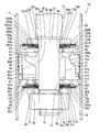
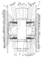
- the fluid pressure buffer 10 of the first embodiment has a cylinder 11 in which a working fluid such as liquid or gas is enclosed.
- the cylinder 11 has a bottomed cylindrical shape in which one end side (upper side in FIG. 1) is open and the other end side (lower side in FIG. 1) is closed.
- a piston 12 is slidably fitted in the cylinder 11.
- the piston rod 13 is inserted in the cylinder 11.
- the piston rod 13 has one end side (the upper side in FIG. 1) extending to the outside of the cylinder 11 and the other end side inserted into the cylinder 11.
- the piston 12 is connected to the other end of the piston rod 13 by a nut 14.
- a rod guide and an oil seal are attached to the opening of the cylinder 11.
- One end side of the piston rod 13 is inserted through a rod guide and an oil seal and extends to the outside.
- the piston 12 includes a first chamber 19 on the bottom side (lower side in FIG. 1) of the cylinder 11 and a second chamber 20 on the side (upper side in FIG. 1) from which the piston rod 13 extends. It is divided into and.
- the piston rod 13 has a main shaft portion 25 and an attachment shaft portion 26 at the inner end portion of the cylinder 11 and having a smaller diameter than the main shaft portion 25.
- the main shaft portion 25 is formed with a step portion 27 along the direction orthogonal to the axis at the end on the mounting shaft portion 26 side.
- the attachment shaft portion 26 is formed with a male screw 28 for screwing the nut 14 into a predetermined range opposite to the main shaft portion 25.
- the piston 12 has a substantially disk-shaped piston body 31 (first piston body) and a substantially disk-shaped piston body 32 (second piston body).
- the piston body 32 is disposed on the first chamber 19 side of the piston body 31, and is thinner in the axial direction than the piston body 31.
- the coupling surface 31a and the coupling surface 32a are coupled in a face-to-face state.
- the coupling surface 31 a is an end surface of the piston body 31 on the piston body 32 side and is a surface orthogonal to the central axis of the piston body 31.
- the coupling surface 32 a is an end surface of the piston body 32 on the piston body 31 side and is a surface orthogonal to the central axis of the piston body 32. That is, the piston 12 includes piston bodies 31 and 32 that are coupled to each other by the coupling surfaces 31a and 32a.
- the piston bodies 31 and 32 are integrally formed by sintering.
- the piston 12 has an annular belt-shaped sliding contact member 33.
- the sliding member 33 is attached to the outer peripheral surface 31 b of the piston body 31 and is in sliding contact with the inner peripheral surface of the cylinder 11.
- the slidable contact member 33 is mounted on the side opposite to the coupling surface 31 a in the axial direction of the piston body 31 with a slight shift.
- the sliding contact member 33 exposes a part of the outer peripheral surface 31 b on the coupling surface 31 a side in the first chamber 19.
- an insertion hole 35 is formed in the center in the radial direction so as to penetrate in the axial direction.
- the insertion hole 35 allows the mounting shaft portion 26 of the piston rod 13 to be inserted without a gap.
- a passage 41 first passage
- a passage 42 second passage
- an annular passage 43 are formed in the piston body 31.
- the passage 41 extends in the axial direction of the piston body 31 outside the insertion hole 35 in the radial direction.
- the passage 42 extends in the axial direction of the piston body 31 outside the insertion hole 35 in the radial direction.
- the annular passage 43 extends over the entire circumference of the piston body 31 at the end opposite to the coupling surface 31a in the axial direction.
- annular passage 43 By forming the annular passage 43, an inner sheet 45 and an outer sheet 46 outside the inner sheet 45 are formed at the end of the piston body 31 opposite to the coupling surface 31 a in the axial direction. Yes.
- the inner sheet 45 is inside the annular passage 43 in the radial direction of the piston body 31.
- the outer sheet 46 is outside the annular passage 43 in the radial direction of the piston body 31. Both the inner sheet 45 and the outer sheet 46 are formed so as to protrude in the axial direction of the piston body 31.
- the annular passage 43 is formed between the inner sheet 45 and the outer sheet 46 in the radial direction of the piston body 31.
- a stepped portion 47 is formed at the end of the piston body 31 opposite to the coupling surface 31a in the axial direction.
- the step portion 47 is formed on the outer side in the radial direction of the outer sheet 46.
- the stepped portion 47 has a stepped shape so as to be closer to the coupling surface 31a than the outer sheet 46 in the axial direction
- a plurality of passages 41 are formed in the piston body 31 at intervals in the circumferential direction.
- a plurality of passages 42 are also formed in the piston body 31 at intervals in the circumferential direction.
- the passages 41 and the passages 42 are alternately arranged in the circumferential direction of the piston body 31.
- the annular passage 43 shown in FIG. 1 is formed so as to connect all of the plurality of passages 41.
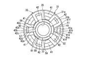
- the passage 41 of the piston body 31 has an opening 51 (first opening) and an opening 52.
- the opening 51 opens on the coupling surface 31 a with the piston body 32.
- the opening 52 opens at the bottom position of the annular passage 43.
- the opening 51 also opens to the outer peripheral surface 31 b that is not covered by the sliding contact member 33 of the piston body 31.
- the opening 51 is continuously opened from the coupling surface 31a to the outer peripheral surface 31b.
- the opening 51 always opens into the first chamber 19.
- the passage 41 is formed with an inner end face 41 a that is the inner end side in the radial direction of the piston body 31.
- the inner end face 41a is formed from the opening 51 to the opening 52 at a fixed position in the radial direction and the circumferential direction. Thereby, the passage 41 has a portion extending linearly in the axial direction of the piston body 31 from the opening 51 to the opening 52.
- the passage 41 has a radial surface 41b, an axial surface 41c, an inclined surface 41d, and an axial surface 41e on the outer end side in the radial direction of the piston body 31.
- the radial surface 41b is on the coupling surface 31a side and is parallel to the coupling surface 31a.
- the axial surface 41 c extends from the inner end edge portion of the radial surface 41 b in the radial direction of the piston body 31 toward the annular passage 43 along the axial direction of the piston body 31.
- the inclined surface 41d extends from the edge of the axial surface 41c opposite to the radial surface 41b to the annular passage 43 side.
- the inclined surface 41d is inclined so as to be located on the inner side in the radial direction of the piston body 31 toward the annular passage 43 side.
- the axial surface 41e extends from the edge of the inclined surface 41d opposite to the axial surface 41c to the annular passage 43 side along the axial direction of the piston body 31.
- the inner end surface 41 a and the axial direction surface 41 e extend to the bottom position of the annular passage 43 to form an opening 52.
- the inner end surface 41a, the axial direction surface 41c, and the axial direction surface 41e form a part of a cylinder centering on the central axis of the piston body 31.
- the passage 41 has a pair of facing surfaces 41 f that extend in the radial direction of the piston body 31 and face each other in the circumferential direction of the piston body 31.
- the passage 41 is formed by an inner end face 41a, a radial face 41b, an axial face 41c, an inclined face 41d, an axial face 41e, and a pair of opposing faces 41f.
- the inner end surface 41a, the radial surface 41b, and the pair of opposed surfaces 41f form an opening 51, and the inner end surface 41a, the axial surface 41e, and the pair of opposed surfaces 41f form an opening 52.
- the width of the opening 51 extending from the inner end surface 41a to the outer peripheral surface 31b is wider than the width of the opening 52 extending from the inner end surface 41a to the axial surface 41e. ing.
- the passage 42 of the piston body 31 has an opening 56 (second opening) and an opening 57 (third opening).
- the opening 56 opens to the coupling surface 31 a with the piston body 32.
- the opening 57 is always open to the second chamber 20 by opening at the position of the stepped portion 47 of the piston body 31.
- the opening 56 opens only on the coupling surface 31a of the piston body 31, and does not open on the outer peripheral surface 31b.
- the passage 42 is formed with an outer end surface 42 a that is the outer end side in the radial direction of the piston body 31.
- the outer end surface 42 a is formed from the opening 56 to the opening 57 at a fixed position in the radial direction and the circumferential direction.
- the passage 42 has a portion extending linearly in the axial direction of the piston body 31 from the opening 56 to the opening 57.
- the passage 42 has an axial surface 42b, an inclined surface 42c, and an axial surface 42d on the inner end side in the radial direction of the piston body 31.
- the axial direction surface 42 b extends from the coupling surface 31 a to the stepped portion 47 side along the axial direction of the piston body 31.
- the inclined surface 42c extends from the end edge of the axial surface 42b opposite to the coupling surface 31a to the stepped portion 47 side.
- the inclined surface 42c is inclined so as to be located on the outer side in the radial direction of the piston body 31 as the distance from the coupling surface 31a increases.
- the axial surface 42d extends from the edge of the inclined surface 42c opposite to the axial surface 42b to the stepped portion 47 along the axial direction of the piston body 31.
- the outer end surface 42a, the axial direction surface 42b, and the axial direction surface 42d form a part of a cylinder centering on the central axis of the piston body 31.
- the passage 42 has a pair of facing surfaces 42 e extending in the radial direction of the piston body 31 and facing each other in the circumferential direction of the piston body 31.
- the passage 42 is formed by an outer end surface 42a, an axial surface 42b, an inclined surface 42c, an axial surface 42d, and a pair of opposing surfaces 42e.
- the outer end surface 42a, the axial direction surface 42b, and the pair of opposing surfaces 42e form an opening 56, and the outer end surface 42a, the axial direction surface 42d, and the pair of opposing surfaces 42e form an opening 57.
- the width of the opening 56 from the outer end surface 42a to the axial surface 42b is wider than the width of the opening 57 from the outer end surface 42a to the axial surface 42d. It has become.
- the position of the axial surface 42 b that is the innermost side of the opening 56 is located on the inner side (center side of the piston body 31) than the position of the inner end face 41 a that is the innermost side of the passage 41. Yes.
- the shortest distance between the center of the piston body 31 and the opening 51 is larger than the shortest distance between the center of the piston body 31 and the opening 56.
- the position of the outer peripheral surface 31 b that is the outer end position of the opening 51 that is the outermost position of the passage 41 is positioned outside the position of the outer end face 42 a that is the outermost position of the passage 42. Yes.
- the shortest distance between the center of the piston body 31 and the opening 51 is shorter than the shortest distance between the center of the piston body 31 and the opening 56 (the distance between the center of the piston body 31 and the axial surface 42b).
- the distance between the center of 31 and the inner end face 41a) is larger.
- the longest distance between the center of the piston body 31 and the opening 56 is larger than the shortest distance between the center of the piston body 31 and the opening 51.
- the opening 51 of the passage 41 and the opening 56 of the passage 42 have portions that open on the same circle having a constant width with the center of the piston body 31 as the center.
- a portion of the opening 56 of the passage 42 that opens on the same circle as the opening 51 of the passage 41 is a main opening 58.
- the main opening 58 is a range outside the intermediate portion in the radial direction of the piston body 31 in the opening 56.
- the position of the axial surface 42 b of the opening 56 that is the innermost position of the passage 42 is located on the inner side of the position of the inner end face 41 a that is the innermost side of the passage 41. From this, the opening 56 is in the radial direction of the piston body 31, the main opening 58 opening in the same range as the opening 51, and the radially inner side of the main opening 58, that is, the radially inner side of the opening 51. And an inner opening 59 that opens up to the bottom.
- the inner opening 59 is an inner area of the opening 56 in the radial direction of the piston body 31.
- annular passage 61 (first annular passage) is formed radially inward of the opening 51 and radially outward of the insertion hole 35.
- the annular passage 61 is open to the coupling surface 31a, and is formed at a position communicating with the opening 56 of the passage 42 so as to cross the opening 56 in the circumferential direction as shown in FIG.
- the annular passage 61 is formed at a position between the insertion hole 35 of the piston body 31 and the inner end face 41a.
- the annular passage 61 is intermittently formed at a position excluding the opening 56 on the same circle with the center of the piston body 31 as the center. As shown in FIG. 1, the annular passage 61 opens at the inner end position of the opening 56 in the radial direction of the piston body 31, that is, at the inner end position of the inner opening 59.
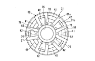
- the piston body 32 has a circular outer shape, and an insertion hole 71 is formed in the center in the radial direction so as to penetrate in the axial direction.
- the insertion hole 71 allows the mounting shaft portion 26 of the piston rod 13 to be inserted without a gap.
- An inner sheet 72 and an outer sheet 73 are formed on the piston body 32 on the side opposite to the piston body 31.
- the inner sheet 72 projects in the axial direction of the piston body 32 outside the insertion hole 71 in the radial direction of the piston body 32.
- the outer sheet 73 protrudes in the axial direction of the piston body 32 outside the inner sheet 72 in the radial direction of the piston body 32.
- the outer sheet 73 may be circular or petal shaped.
- the inner sheet 72 has an annular shape surrounding the insertion hole 71, and more specifically, has an annular shape whose center coincides with the insertion hole 71.
- the outer sheet 73 has an annular shape surrounding the inner sheet 72, and more specifically, has an annular shape with the center coincided with the inner sheet 72.
- An annular passage 78 that is recessed in the axial direction of the piston body 32 is formed between the inner sheet 72 and the outer sheet 73.
- the piston bodies 31 and 32 are fitted to the mounting shaft portion 26 of the piston rod 13 in the insertion holes 35 and 71 to bring the coupling surfaces 31a and 32a into a face-to-face state. Then, the outer peripheral position of the piston body 32 is arranged outside the outer end position of the opening 56 of the passage 42 in the radial direction. As a result, the piston body 32 is coupled to the piston body 31 so as to prevent direct communication between the opening 56 of the passage 42 and the first chamber 19. Thus, even if the piston body 32 is coupled to the piston body 31, the opening 51 of the passage 41 of the piston body 31 has a shape in which the end portion on the coupling surface 31a side comes out radially outward. The room 19 is always open.
- a passage 76 third passage
- an annular passage 77 second annular passage
- a plurality of passages 76 extend in the axial direction of the piston body 32 (only one is shown in FIG. 1).
- the annular passage 77 extends over the entire circumference of the piston body 32 at the position of the coupling surface 32 a and connects the plurality of passages 76.
- the plurality of passages 76 are formed at equal intervals in the circumferential direction of the piston body 32 at positions equidistant from the center of the piston body 32.
- the annular passage 77 has an annular shape centered on the center of the piston body 32.
- the plurality of passages 76 and the annular passage 77 are arranged at the positions of the inner opening 59 of the passage 42 and the annular passage 61 in the radial direction of the piston bodies 31 and 32 when the piston bodies 31 and 32 are coupled. Therefore, it always communicates with the inner opening 59 and the annular passage 61.
- a spacer 100, a disk 101, a spacer 102, and a regulating member 103 are provided in this order from the axial piston body 31 side. Further, on the opposite side of the piston body 32 from the piston body 31 in the axial direction, a disk 105, a spacer 106, and a regulating member 107 are provided in this order from the piston body 32 side.
- the spacer 100, the disk 101, the spacer 102, the regulating member 103, the disk 105, the spacer 106, and the regulating member 107 are all in an annular shape, and the mounting shaft portion 26 of the piston rod 13 has no gap between the inner peripheral portions. It is inserted.
- the spacer 106 is a common part with the spacer 102, and the restriction member 107 is a common part with the restriction member 103.
- the mounting shaft portion 26 of the piston rod 13 includes an inner peripheral portion of the regulating member 103, an inner peripheral portion of the spacer 102, an inner peripheral portion of the disk 101, an inner peripheral portion of the spacer 100, an insertion hole 35 of the piston body 31, and a piston body 32.
- a piston body 32 is inserted in this order into the insertion hole 71, the inner periphery of the disk 105, the inner periphery of the spacer 106, and the inner periphery of the restricting member 107.
- the nut 14 is screwed onto the male screw 28 of the mounting shaft 26.
- the restriction member 103, the spacer 102, the disk 101, the spacer 100, the piston body 31, the piston body 32, the disk 105, the spacer 106, and the restriction member 107 are all laminated by restricting the radial movement by the mounting shaft portion 26.
- the stepped portion 27 of the piston rod 13 and the nut 14 are sandwiched.
- the disc 101 and the disc 105 are clamped so that only the inner peripheral side of the disc 101 and the disc 105 cannot move in the axial direction with respect to the piston rod 13.
- the outer diameter of the spacer 100 is slightly larger than the outer diameter of the sheet surface 45a of the inner sheet 45.
- the disk 101 has an outer diameter slightly larger than the outer diameter of the seat surface 46 a of the outer sheet 46, and covers the annular passage 43 so as to be closed.
- the disk 101 is configured by laminating a plurality of single disks 110 having the same diameter disk shape. Among these single discs 110, those that come into contact with the seat surface 46 a are formed with a fixed orifice 111 that always communicates the annular passage 43 with the second chamber 20.
- the single disk 110 has a flat shape, that is, a flat plate shape in which the front and back surfaces are positioned at fixed positions in the axial direction, and therefore the disk 101 is similarly flat. It is flat.
- the outer diameter of the spacer 102 is slightly smaller than the outer diameter of the sheet surface 45 a of the inner sheet 45.
- the outer diameter of the regulating member 103 is slightly smaller than the inner diameter of the seat surface 46 a of the outer sheet 46.
- the tip height position in the protruding direction of the inner sheet 45 and the outer sheet 46 formed on the second chamber 20 side of the piston body 31 is the tip height in the protruding direction of the inner sheet 45 when the protruding direction is a positive direction.
- the tip height position in the protruding direction of the outer sheet 46 is slightly higher than the position. That is, the height position in the protruding direction of the sheet surface 46a at the leading end in the protruding direction of the outer sheet 46 is higher than the height position in the protruding direction of the sheet surface 45a at the leading end in the protruding direction of the inner sheet 45. More specifically, the height position in the protruding direction of the sheet surface 46a of the outer sheet 46 is higher than the height position of the surface opposite to the sheet surface 45a of the spacer 100 in contact with the sheet surface 45a of the inner sheet 45. Is higher.
- the disc 101 is assembled to the piston rod 13 so as to be pressed against the spacer 100 that contacts the seat surface 45a of the inner sheet 45.
- an annular passage 43 provided in the piston body 31 is seated on the seat surface 46 a of the outer seat 46 of the piston body 31.
- the plurality of passages 41 are closed.
- the disk 101 is slightly deformed so that the outer peripheral side is located on the opposite side of the piston body 32 in the axial direction from the inner peripheral side.
- the pressure in the first chamber 19 is increased above the pressure in the second chamber 20 by the piston 12 that moves together with the piston rod 13. Then, this pressure is introduced into the plurality of passages 41 from the openings 51 that are always open, and acts on the disc 101 via the annular passage 43. Then, the disc 101 is separated from the outer seat 46 and opens the annular passage 43 and the plurality of passages 41. Thereby, the working fluid flows from the first chamber 19 to the second chamber 20 through the plurality of passages 41 and the annular passage 43 at a flow rate corresponding to the valve opening amount of the disc 101 and the outer seat 46.
- An annular outer sheet 46 projecting from the piston body 31 so as to surround the annular passage 43 and a disk 101 for opening and closing the second chamber 20 side of the annular passage 43 constitute a contraction-side damping force generation mechanism 121.
- the damping force generation mechanism 121 is provided for the annular passage 43 and the plurality of passages 41 to suppress the flow of the working fluid and generate a damping force.
- the damping force generation mechanism 121 is disposed on the second chamber 20 side of the piston body 31.
- the outer diameter of the disk 105 is larger than the outer diameter of the sheet surface 73a on the protruding front end side of the outer sheet 73, and covers the annular passage 78 so as to be closed.
- the disk 105 is configured by laminating a plurality of disk-shaped single disks 125 having the same diameter, and of these, the annular passage 78 is always in communication with the first chamber 19 in contact with the seat surface 73a.
- a fixed orifice 126 is formed.
- the single disk 125 In a natural state before assembly to the piston rod 13, the single disk 125 has a flat shape, that is, a flat plate shape in which the front and back surfaces are positioned at fixed positions in the axial direction, and thus the disk 105 is similarly flat. It is flat.
- the spacer 106 has an annular shape whose outer diameter is slightly larger than the outer diameter of the sheet surface 72 a of the inner sheet 72.
- the regulating member 107 has an annular shape whose outer diameter is smaller than the inner diameter of the sheet surface 73 a of the outer sheet 73.
- the leading edge height position in the protruding direction of the inner sheet 72 and the outer sheet 73 is the outer sheet 73 than the leading edge height position in the protruding direction of the inner sheet 72 when the protruding direction (downward direction in FIG. 1) is the positive direction.
- the tip height position in the protruding direction is higher. That is, the height position in the protruding direction of the sheet surface 73a at the leading end in the protruding direction of the outer sheet 73 is higher than the height position in the protruding direction of the sheet surface 72a at the leading end in the protruding direction of the inner sheet 72.
- the disc 105 When the disc 105 is assembled to the piston rod 13 together with other components, the disc 105 is pressed against the inner sheet 72 and placed on the outer sheet 73. In this state, the disc 105 is slightly deformed so that the outer peripheral side is separated from the piston body 31 in the axial direction than the inner peripheral side.
- the disk 105 is seated on the seat surface 73a of the outer seat 73 of the piston body 32 when the first chamber 19 and the second chamber 20 are in a non-operating state with no pressure difference. In this state, the disk 105 closes the annular passage 78, the plurality of passages 76 and the annular passage 77 provided in the piston body 32, and the annular passage 61 and the plurality of passages 42 provided in the piston body 31.
- the pressure of the second chamber 20 is increased from the pressure of the first chamber 19 by the piston 12 that moves together with the piston rod 13. Then, this pressure is always introduced into the plurality of passages 42 from the openings 57 that are open, and acts on the disk 105 via the annular passages 61 and 77, the plurality of passages 76, and the annular passage 78. Then, the disc 105 is separated from the outer seat 73 and opens the annular passage 78.
- the second chamber 20 is changed from the second chamber 20 to the first chamber 19 through the plurality of passages 42, the annular passages 61 and 77, the plurality of passages 76, and the annular passage 78 according to the valve opening amount of the disc 105 and the outer seat 73.
- the working fluid flows at the flow rate.
- the piston rod 13 moves to the extending side and the piston 12 slides in the cylinder 11 together with the plurality of passages 42, the annular passages 61 and 77, the plurality of passages 76, and the annular passage 78, this sliding is performed.
- the working fluid flows from the second chamber 20 toward the first chamber 19 by the movement.
- An annular outer sheet 73 projecting from the piston body 32 so as to surround the annular passage 78 and a disk 105 that opens and closes the first chamber 19 side of the annular passage 78 constitute an extension-side damping force generation mechanism 131.
- the extension-side damping force generating mechanism 131 is provided for the plurality of passages 42, the annular passages 61 and 77, the plurality of passages 76, and the annular passage 78, and suppresses the flow of the working fluid to generate a damping force.
- the damping force generation mechanism 131 is disposed on the first chamber 19 side of the piston body 32.
- Patent Document 1 a piston structure in which a pair of piston halves formed with passages are joined together while matching the opening positions of the passages on the coupling surfaces to form an extension side passage and a contraction side passage.
- a circumferential positioning portion having a concave shape and a convex shape is formed on the coupling surfaces of the pair of piston halves.
- Patent Document 2 discloses a structure similar to that of Patent Document 1, and although there is no description, a circumferential positioning portion is required. If the structure requires positioning in the circumferential direction as in Patent Documents 1 and 2, a circumferential alignment operation is required in the assembling work, which causes an increase in cost.
- the convex portion protruding from the coupling surface may be lost due to contact with other components, which is difficult to apply to an automatic component supply apparatus, and this also contributes to an increase in cost.
- the passage in the oblique hole is not necessary for positioning in the circumferential direction, but the oblique hole needs to be formed by cutting, resulting in an increase in cost.
- the coupling surface of Patent Document 3 is provided with a plurality of either one of an extension side passage and a contraction side passage on the same circle outside the insertion hole of the piston rod, and the other passage on the outside thereof. Therefore, a plurality of structures are provided on the same circle. Therefore, the circle formed by one passage becomes a small circle, and it is difficult to secure the passage opening area, and it is difficult to meet the demand for a large flow rate with a small piston diameter.
- the piston body 31 opens the opening 51 that opens to the first chamber 19 of the passage 41 to the coupling surface 31a with the piston body 32, and the second.
- An opening 56 of the passage 42 communicating with the chamber 20 is opened on the coupling surface 31a.
- the inner opening 59 of the opening 56 is opened to the inside in the radial direction from the opening 51, and the inner opening 59 is communicated with a passage 76 formed in the piston body 32. Therefore, the passage 42 and the passage 76 can be communicated without communicating the passage 41 and the passage 76 without positioning the piston body 31 and the piston body 32 in the circumferential direction.
- the circumferential positioning portion is not required for the piston bodies 31 and 32, and the alignment operation in the circumferential direction is not required in the assembly operation.
- a convex portion for positioning in the circumferential direction is not necessary, application to an automatic component supply device is possible.
- the passages 41 and 42 extend in the axial direction of the piston body 31, it is not necessary to form them by cutting, and they can be formed by sintering. Therefore, cost can be reduced.
- the passages 41 and 42 have openings formed alternately on the same circle from the outer peripheral side to the inner peripheral side of the coupling surface 31a, the openings are divided into the inner and outer peripheries as shown in Patent Document 3. A large opening area can be secured as compared with the arrangement.
- annular passage 61 is formed at a position that is radially inward of the piston body 31 and communicates with the opening 56, the passage 42 and the passage 76 are communicated without increasing the number of the passages 76. It becomes possible to make it.
- annular passage 77 is formed at a position communicating with the inner opening 59 of the piston body 32. For this reason, the passage 42 and the passage 76 can be communicated with each other without increasing the number of the passages 76. Note that only one of the annular passage 61 and the annular passage 77 may be formed. As shown in FIG. 3, if the number of the passages 76 is set so that one of the passages 76 communicates with the passage 42 regardless of the circumferential positional relationship between the piston bodies 31 and 32, the annular passage 61 and It is possible not to provide both of the annular passages 77 (in FIG. 3, the closed range of the passage 76 by the piston body 31 is indicated by hatching).
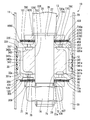
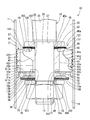
- the height difference between the seat surface 72a of the inner sheet 72 and the seat surface 73a of the outer sheet 73 is larger than that of the first embodiment.
- the piston body 32 of the second embodiment has an annular intermediate sheet 201 that protrudes in the axial direction of the piston body 32 between the inner sheet 72 and the outer sheet 73 on the opposite side to the piston body 31. Is formed.
- the intermediate sheet 201 has an annular shape surrounding the inner sheet 72, and more specifically, has an annular shape whose center coincides with the inner sheet 72.
- a plurality of passages 76 (only one place shown in FIG. 4) is formed between the inner sheet 72 and the intermediate sheet 201 and in the vicinity of the inner sheet 72.
- Between the inner sheet 72 and the intermediate sheet 201 is an annular passage 203 that is recessed in the axial direction of the piston body 32, and a plurality of passages 76 are opened in the annular passage 203.
- the radially inner side of the outer sheet 73 is an annular passage 204 that is recessed in the axial direction of the piston body 32.
- the disk 105 that contacts the outer sheet 73 is provided so as to close the annular passage 204.
- the fixed orifice 126 provided in the single disk 125 that contacts the outer sheet 73 among the single disks 125 constituting the disk 105 always connects the annular passage 204 to the first chamber 19.
- a disk 210 and a spacer 211 are provided in this order from the piston body 32 side.
- the disc 210 and the spacer 211 have an annular shape, and the mounting shaft portion 26 of the piston rod 13 is inserted through the inner peripheral portion without any gap.
- the outer diameter of the disk 210 is slightly larger than the outer diameter of the most projecting sheet surface 201a of the intermediate sheet 201, and covers the annular passage 203 so as to be closed.
- the disc 210 is configured by laminating a plurality of disc-shaped single disks 220 having the same diameter, and of these, the annular passage 203 is always in communication with the annular passage 204 in contact with the sheet surface 201a.
- a fixed orifice 221 is formed.
- the single disk 220 has a flat shape, that is, a flat plate shape in which the front and back surfaces are located at fixed positions in the axial direction, and therefore the disk 210 is similarly flat. It is flat.
- the outer diameter of the spacer 211 is slightly larger than the outer diameter of the sheet surface 72 a of the inner sheet 72.
- the leading edge height position in the protruding direction of the inner sheet 72 and the intermediate sheet 201 is higher than the leading edge height position in the protruding direction of the inner sheet 72 when the protruding direction (downward direction in FIG. 1) is the positive direction.
- the tip height position in the protruding direction is higher. That is, the height position in the protruding direction of the sheet surface 201a at the leading end in the protruding direction of the intermediate sheet 201 is slightly higher than the height position in the protruding direction of the sheet surface 72a at the leading end in the protruding direction of the inner sheet 72.
- the disc 210 When the disc 210 is assembled to the piston rod 13 together with other components, the disc 210 is pressed against the inner sheet 72 and placed on the intermediate sheet 201. In this state, the disk 210 is slightly tilted so that the outer peripheral side is located on the opposite side of the axial direction piston body 31 from the inner peripheral side.
- the disk 105 stacked on the disk 210 via the spacer 211 is assembled to the piston rod 13 together with other components, the disk 105 is pressed against the spacer 211 and placed on the outer sheet 73. In this state, the disk 105 is slightly tilted so that the outer peripheral side is located on the opposite side of the axial direction piston body 31 from the inner peripheral side.
- the disc 105 When there is no pressure difference between the first chamber 19 and the second chamber 20, the disc 105 is seated on the seat surface 73 a of the outer seat 73 of the piston body 32, and the disc 210 is the intermediate seat of the piston body 31.
- the seat 201 is seated on the seat surface 201a.
- the discs 105 and 210 include the annular passages 203 and 204 provided in the piston body 32, the plurality of passages 76 and the annular passage 77, and the annular passage 61 and the plurality of passages 42 provided in the piston body 31. Closed.
- the pressure of the second chamber 20 is increased from the pressure of the first chamber 19 by the piston 12 that moves together with the piston rod 13. Then, this pressure is always introduced into the plurality of passages 42 from the openings 57 that are open, and acts on the disk 210 via the annular passages 61 and 77, the plurality of passages 76, and the annular passage 203.
- the pressure in the second chamber 20 opens, for example, the discs 210 from the intermediate sheet 201 and the discs 105 from the outer sheet 73 to open the annular passages 203 and 204.
- the valve opening amount of the disc 210 and the intermediate seat 201 is changed from the second chamber 20 to the first chamber 19 via the plurality of passages 42, the annular passages 61 and 77, the plurality of passages 76, and the annular passages 203 and 204.
- the working fluid flows at a flow rate corresponding to the valve opening amount of the disk 105 and the outer seat 73. That is, when the piston rod 13 moves to the extension side in the plurality of passages 42, the annular passages 61 and 77, the plurality of passages 76, and the annular passages 203 and 204, and the piston 12 slides in the cylinder 11 together with the piston rod 13, This sliding causes the working fluid to flow from the second chamber 20 toward the first chamber 19.
- the disc 210 that opens and closes the disc and the disc 105 that opens and closes the first chamber 19 side of the annular passage 204 constitute an extension-side damping force generation mechanism 231.
- the extension-side damping force generation mechanism 231 is provided for the plurality of passages 42, the annular passages 61 and 77, the plurality of passages 76, and the annular passages 203 and 204, and generates a damping force by suppressing the flow of the working fluid. .
- the damping force generation mechanism 231 is disposed on the first chamber 19 side of the piston body 32.
- the sheet surface 45a of the inner sheet 45 on the second chamber 20 side in the axial direction of the piston body 31 and the sheet surface 46a of the outer sheet 46 are aligned in the axial direction.
- path 43 is expanded to the radial direction inner side range rather than 1st Embodiment.
- the piston body 32A (3rd piston body) of the piston body 32 by the side of the 1st chamber 19 and the common component is provided in the seat surface 45a of the inner side sheet 45, and the seat surface 46a of the outer side sheet
- the piston body 32A includes a coupling surface 32Aa similar to the coupling surface 32a, an insertion hole 71A similar to the insertion hole 71, an inner sheet 72A similar to the inner sheet 72, and a sheet surface 72Aa similar to the sheet surface 72a.
- the piston body 32A includes an outer sheet 73A similar to the outer sheet 73, a sheet surface 73Aa similar to the sheet surface 73a, an intermediate sheet 201A similar to the intermediate sheet 201, and a sheet surface 201Aa similar to the sheet surface 201a.
- the piston body 32A has a plurality of passages 76A (fourth passage) similar to the plurality of passages 76, an annular passage 77A similar to the annular passage 77, an annular passage 203A similar to the annular passage 203, and the annular passage 204. And an annular passage 204A.
- the piston body 32A has the coupling surface 32Aa as the seat surface 45a of the inner sheet 45 and the seat surface 46a of the outer sheet 46 with the inner sheet 72A, outer sheet 73A and intermediate sheet 201A facing away from the piston body 31. It is made to contact.
- the piston body 32 ⁇ / b> A is coupled to the piston body 31 so as to prevent direct communication between the annular passage 43 and the second chamber 20.
- the annular passage 77 ⁇ / b> A of the piston body 32 ⁇ / b> A overlaps the annular passage 43 of the piston body 31 in the radial direction, and is always open to the annular passage 43.
- the annular passage 77A and the annular passage 43 communicate with each other regardless of the circumferential positions of the piston body 31 and the piston body 32A. Therefore, the circumferential positioning of the piston body 31 and the piston body 32A is not necessary.
- the disk 105A that is a common part with the disk 105 instead of the spacer 100 and the disk 101 of the first embodiment, the disk 105A that is a common part with the disk 105, the disk 210A that is a common part with the disk 210, and the spacer 211 and the common part.
- a spacer 211A That is, on the second chamber 20 side in the axial direction of the piston body 31, the piston body 32A, the disk 210A, the spacer 211A, the disk 105A, the spacer 102, and the regulating member 103 are provided in this order from the axial piston body 31 side. Yes.
- the disk 105A has a plurality of single disks 125A, and among these, a fixed orifice 126A is formed in contact with the sheet surface 73Aa.
- the fixed orifice 126A always connects the annular passage 204A to the second chamber 20.
- the disk 210A has a plurality of single disks 220A, and a fixed orifice 221A is formed on the disk 210A that contacts the sheet surface 201Aa.
- the fixed orifice 221A always communicates between the annular passages 203A and 204A.
- the disc 210A When the disc 210A is assembled to the piston rod 13 together with other components, the disc 210A is pressed against the inner sheet 72A and placed on the intermediate sheet 201A. In this state, the disc 210A is slightly tilted so that the outer peripheral side is located on the opposite side of the axial direction piston body 31 from the inner peripheral side. Further, when the disk 105A is assembled to the piston rod 13 together with other components, the disk 105A is pressed against the spacer 211A and placed on the outer sheet 73A. In this state, the disc 105A is slightly tilted so that the outer peripheral side is located on the opposite side of the axial direction piston body 31 from the inner peripheral side.
- the disc 105A When there is no pressure difference between the first chamber 19 and the second chamber 20, the disc 105A is seated on the seat surface 73Aa of the outer seat 73A of the piston body 32A, and the disc 210A is the intermediate seat of the piston body 31A. Sit on the seat surface 201Aa of 201A.
- the discs 105A and 210A include the annular passages 203A and 204A provided in the piston body 32A, the plurality of passages 76A and the annular passage 77A, and the annular passage 43 and the plurality of passages 41 provided in the piston body 31. Closed.
- the pressure in the first chamber 19 is increased above the pressure in the second chamber 20 by the piston 12 that moves together with the piston rod 13. Then, this pressure is always introduced into the plurality of passages 41 from the openings 51, and acts on the disc 210A via the annular passages 43 and 77A, the plurality of passages 76A and the annular passage 203A.
- the pressure in the first chamber 19 opens, for example, the annular passages 203A and 204A by separating the disc 210A from the intermediate sheet 201A and the disc 105A from the outer sheet 73A.
- valve opening amount of the disc 210A and the intermediate seat 201A from the first chamber 19 to the second chamber 20 through the plurality of passages 41, the annular passages 43 and 77A, the plurality of passages 76A and the annular passages 203A and 204A.
- the working fluid flows at a flow rate corresponding to the valve opening amount of the disk 105A and the outer seat 73A.
- annular intermediate sheet 201A protruding from the piston body 32A so as to surround the annular passage 203A, an annular outer sheet 73A protruding from the piston body 32A so as to surround the annular passage 204A, and the annular passage 203A side of the annular passage 203A
- the disc 210A that opens and closes the disc and the disc 105A that opens and closes the second chamber 20 side of the annular passage 204A constitute a contraction-side damping force generation mechanism 231A.
- the compression-side damping force generating mechanism 231A is provided for the plurality of passages 41, the annular passages 43 and 77A, the plurality of passages 76A, and the annular passages 203A and 204A, and generates a damping force by suppressing the flow of the working fluid. .
- the damping force generation mechanism 231A is disposed on the second chamber 20 side of the piston body 32A.
- a piston body 32A having a passage 76A communicating with the passage 41 is provided on the second chamber 20 side of the piston body 31. Therefore, the design freedom of the damping force generation mechanism 231A can be increased.
- the piston 12 of the third embodiment includes a substantially disc-shaped piston body 331 (first piston body), a piston body 32 (second piston body) substantially similar to the piston body 32 of the first embodiment, and this piston. It has a piston body 32C (third piston body) which is a common part with the body 32.
- the piston body 32 is disposed on the first chamber 19 side of the piston body 331 and is thinner in the axial direction than the piston body 331.
- the piston body 32C is disposed on the second chamber 20 side of the piston body 331.
- the coupling surface 331a and the coupling surface 32a are coupled in a face-to-face state.
- the coupling surface 331c and the coupling surface 32Ca are coupled in a face-to-face state.
- the coupling surface 331 a is an end surface of the piston body 331 on the piston body 32 side and is a surface orthogonal to the central axis of the piston body 331.
- the coupling surface 331c is an end surface of the piston body 331 on the piston body 32C side and is a surface orthogonal to the central axis of the piston body 331.
- the piston 12 of the third embodiment includes piston bodies 331 and 32 coupled by mutual coupling surfaces 331a and 32a and piston bodies 331 and 32C coupled by mutual coupling surfaces 331c and 32Ca.
- the piston body 331 is integrally formed by sintering.
- the sliding contact member 33 is attached to the outer peripheral surface 331b of the piston body 331.
- the sliding member 33 is mounted at an intermediate position in the axial direction of the piston body 331.
- the sliding member 33 exposes a part of the outer peripheral surface 331 b on the coupling surface 331 a side in the first chamber 19 and a part of the outer peripheral surface 331 b on the coupling surface 331 c side exposed in the second chamber 20.
- an insertion hole 335 is formed in the center in the radial direction so as to penetrate in the axial direction.
- the insertion hole 335 allows the mounting shaft portion 26 of the piston rod 13 to be inserted without a gap.
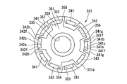
- the piston body 331 includes a passage 341 (first passage), a passage 342 (second passage), an annular passage 343, and an annular passage 361 (first annular passage).
- the passages 341 and 342 extend in the axial direction of the piston body 331 outside the radial insertion hole 335.
- the annular passage 343 extends over the entire periphery of the piston body 331 at the end portion on the axial coupling surface 331c side.
- the annular passage 361 extends over the entire circumference of the piston body 331 at the end portion on the side of the coupling surface 331a in the axial direction.
- the passage 341 and the passage 342 have a point-symmetric shape with respect to the center of the piston body 331.
- the annular passages 343 and 361 have the same width and position in the radial direction of the piston body 331 and the same depth.
- the entire piston body 331 has a point-symmetric shape with respect to the center thereof.
- the piston body 331 has coupling surfaces 331a and 331c having the same shape.
- the piston body 331 has a shape with no distinction between front and back. That is, the piston body 331 has no directionality in attachment when the attachment shaft portion 26 is inserted through the insertion hole 335.
- a plurality of passages 341 are formed in the piston body 331 at intervals in the circumferential direction.
- a plurality of passages 342 are also formed in the piston body 331 at intervals in the circumferential direction.
- the passages 341 and the passages 342 are alternately arranged in the circumferential direction of the piston body 331.
- the annular passage 343 shown in FIG. 6 is formed so as to connect all the plurality of passages 341.
- the annular passage 361 shown in FIG. 7 is formed so as to connect all of the plurality of passages 342.
- the passage 341 of the piston body 331 has an opening 351 (first opening) and an opening 352.
- the opening 351 opens on the coupling surface 331 a with the piston body 32.
- the opening 352 opens to the coupling surface 331c with the piston body 32C.
- the opening 352 communicates with the annular passage 343.
- the opening 351 is also opened on the outer peripheral surface 331b not covered with the sliding member 33 of the piston body 331.
- the opening 351 is continuously opened from the coupling surface 331a to the outer peripheral surface 331b.
- the opening 351 always opens in the first chamber 19.
- the opening 352 opens only on the coupling surface 331c of the piston body 331, and does not open on the outer peripheral surface 331b.
- the passage 341 has an inner wall surface 341 a that extends linearly in the axial direction on the inner side in the radial direction of the piston body 331.
- the passage 341 has a radial surface 341b and an axial surface 341c outside the piston body 331 in the radial direction.
- the radial direction surface 341b is on the coupling surface 331a side and is parallel to the coupling surface 331a.
- the axial surface 341c extends from the inner edge of the radial surface 341b in the radial direction of the piston body 331 to the coupling surface 331c along the axial direction of the piston body 331.
- the inner wall surface 341a and the axial direction surface 341c are part of a cylinder centering on the central axis of the piston body 331.
- the passage 341 extends in the radial direction of the piston body 331 and is opposed to each other in the circumferential direction of the piston body 331, and the passage 341 extends in the radial direction of the piston body 331 and is mutually connected to the piston body 331.
- a pair of facing surfaces 341g facing each other in the circumferential direction.
- the pair of opposed surfaces 341g is longer in the circumferential direction of the piston body 331 than the pair of opposed surfaces 341f.
- the passage 341 has a pair of facing surfaces 341 h that extend in the radial direction of the piston body 331 and face each other in the circumferential direction of the piston body 331.
- the pair of opposed surfaces 341h is longer in the circumferential direction of the piston body 331 than the pair of opposed surfaces 341f.
- the passage 341 is formed by an inner wall surface 341a, a radial surface 341b, an axial surface 341c, a pair of facing surfaces 341f, a pair of facing surfaces 341g, and a pair of facing surfaces 341h. As shown in FIG.
- the inner wall surface 341a, the radial surface 341b, and the pair of opposed surfaces 341g form an opening 351
- the axial surface 341c and the pair of opposed surfaces 341f are formed in the annular passage 343 as shown in FIG.
- An opening 352 that communicates is formed.
- the passage 342 of the piston body 331 includes an opening 356 similar to the opening 352 and an opening 357 similar to the opening 351.
- the opening 356 opens to the coupling surface 331a with the piston body 32.
- the opening 357 opens from the coupling surface 331c to the piston body 32C to the outer peripheral surface 331b.
- the opening 357 is always open to the second chamber 20.
- the opening 356 opens only on the coupling surface 331a of the piston body 31, and does not open on the outer peripheral surface 331b.
- the passage 342 includes an inner wall surface 342a similar to the inner wall surface 341a, a radial surface 342b similar to the radial surface 341b, and an axial surface 342c similar to the axial surface 341c.
- the passage 342 is formed by an inner wall surface 342a, a radial surface 342b, an axial surface 342c, a pair of facing surfaces 342f, a pair of facing surfaces 342g, and a pair of facing surfaces 342h.
- the inner wall surface 342a, the radial surface 342b, and the pair of opposed surfaces 342g form an opening 357
- the axial surface 342c and the pair of opposed surfaces 342h form an opening 356 that communicates with the annular passage 361.
- the annular passage 343 provided in the coupling surface 331 c communicates with the opening 352 of the passage 341 and is separated from the opening 357 of the passage 342.
- the opening 351 of the passage 341 and the opening 356 of the passage 342 have portions that open on the same circle having a constant width with the center of the piston body 331 as the center.
- a portion of the opening 356 of the passage 342 that opens on the same circle as the opening 351 of the passage 341 in this way is a main opening 358.
- the main opening 358 is a region outside the opening 356 in the radial direction of the piston body 331.
- the opening 356 includes the main opening 358 that opens in the same range as the opening 351 in the radial direction of the piston body 331, and the inner side that opens radially inward of the main opening 358, that is, radially inward of the opening 351.
- the inner opening 359 is an inner area of the opening 356 in the radial direction of the piston body 331.
- the annular passage 361 provided in the coupling surface 331 a communicates with the opening 356 of the passage 342 and is separated from the opening 351 of the passage 341.
- the opening 357 of the passage 342 and the opening 352 of the passage 341 have portions that open on the same circle having a constant width with the center of the piston body 331 as the center.
- a portion of the opening 352 of the passage 341 that opens on the same circle as the opening 357 of the passage 342 in this way is a main opening 458.
- the main opening 458 is a range outside the opening 352 in the radial direction of the piston body 331.
- the opening 352 has a main opening 458 that opens in the same range as the opening 357 in the radial direction of the piston body 331, and an inner side that opens radially inward of the main opening 458, that is, inward of the opening 357 in the radial direction. And an opening 459.
- the inner opening 459 is an inner area of the opening 352 in the radial direction of the piston body 331.
- annular passage 361 is formed on the coupling surface 331 a side of the piston body 331, radially inward from the opening 351 and radially outward from the insertion hole 335.
- the annular passage 361 is open to the coupling surface 331a, and is formed at a position communicating with the opening 356 of the passage 342 so as to cross the opening 356 in the circumferential direction.
- the annular passage 361 is formed at a position between the insertion hole 335 of the piston body 331 and the inner wall surface 341a.
- the annular passage 361 is formed on the same circle with the center of the piston body 331 as the center.
- the annular passage 361 opens at the inner end position of the opening 356 in the radial direction of the piston body 331, that is, at the inner end position of the inner opening 359.
- annular passage 343 is formed on the coupling surface 331 c side of the piston body 331, radially inward of the opening 357 and radially outward of the insertion hole 335.
- the annular passage 343 is open to the coupling surface 331c, and is formed at a position communicating with the opening 352 of the passage 341 so as to cross the opening 352 in the circumferential direction as shown in FIG.
- the annular passage 343 is formed at a position between the insertion hole 335 of the piston body 331 and the inner wall surface 342a.
- the annular passage 343 is formed on the same circle with the center of the piston body 331 as the center.
- the annular passage 343 opens at the inner end position of the opening 352 in the radial direction of the piston body 331, that is, the inner end position of the inner opening 459.
- the radial width of the annular passage 77 is wider than that of the first and second embodiments, and as shown in FIG. It is provided on the radially outer side than the first and second embodiments.
- the piston bodies 331 and 32 are fitted to the mounting shaft portion 26 of the piston rod 13 in the insertion holes 335 and 71 to bring the coupling surfaces 331a and 32a into a face-to-face state. Then, the outer peripheral position of the piston body 32 is disposed outside the outer end position of the opening 356 of the passage 342 in the radial direction. As a result, the piston body 32 is coupled to the piston body 331 so as to prevent direct communication between the opening 356 of the passage 342 and the first chamber 19. Thus, even if the piston body 32 is coupled to the piston body 331, the opening 351 of the passage 341 of the piston body 331 has a shape in which the end portion on the coupling surface 331a side comes out radially outward. The room 19 is always open.
- the plurality of passages 76 and the annular passage 77 of the piston body 32 are arranged at the position of the annular passage 361 in the radial direction of the piston bodies 331 and 32 when the piston bodies 331 and 32 are in a coupled state. It always communicates with the inner opening 359 of the passage 342 and the annular passage 361.
- the piston body 32C has an insertion hole 71C similar to the insertion hole 71, an inner sheet 72C similar to the inner sheet 72, an outer sheet 73C similar to the outer sheet 73, and an annular passage 78C similar to the annular passage 78. is doing.
- the inner sheet 72C has a sheet surface 72Ca similar to the sheet surface 72a
- the outer sheet 73C has a sheet surface 73Ca similar to the sheet surface 73a.
- the piston bodies 331 and 32C are fitted to the mounting shaft portion 26 of the piston rod 13 in the insertion holes 335 and 71C to bring the coupling surfaces 331c and 32Ca into a face-to-face state. Then, in the radial direction, the outer peripheral position of the piston body 32 ⁇ / b> C is disposed outside the outer end position of the opening 352 of the passage 341. Thus, the piston body 32C is coupled to the piston body 331 so as to prevent direct communication between the opening 352 of the passage 341 and the second chamber 20.
- the opening 357 of the passage 342 of the piston body 331 has a shape in which the end portion on the coupling surface 331c side comes out radially outward.
- the two chambers 20 are always open.
- the piston body 32 ⁇ / b> C has a passage 76 ⁇ / b> C (fourth passage) similar to the passage 76 and an annular passage 77 ⁇ / b> C similar to the annular passage 77.
- the plurality of passages 76C and the annular passage 77C are disposed at the position of the annular passage 343 in the radial direction of the piston bodies 331 and 32C when the piston bodies 331 and 32C are coupled to each other. It always communicates with the opening 459 and the annular passage 343.
- a disk 105C similar to the disk 105, a spacer 106C similar to the spacer 106, and a restriction similar to the restriction member 107 are sequentially arranged from the side of the piston body 32C in the axial direction.
- a member 107C is provided.
- the disk 105C is configured by laminating a plurality of single disks 125C similar to the single disk 125, and a fixed orifice 126C similar to the fixed orifice 126 is formed in contact with the sheet surface 73Ca.
- the pressure of the second chamber 20 is increased from the pressure of the first chamber 19 by the piston 12 that moves together with the piston rod 13. Then, this pressure is introduced into the plurality of passages 342 from the openings 357 that are always open, and acts on the disc 105 via the annular passages 361 and 77, the plurality of passages 76, and the annular passage 78. Then, the disc 105 is separated from the outer seat 73 and opens the annular passage 78.
- the second chamber 20 is changed from the second chamber 20 to the first chamber 19 through the plurality of passages 342, the annular passages 361 and 77, the plurality of passages 76, and the annular passage 78 according to the valve opening amount of the disc 105 and the outer seat 73.
- the working fluid flows at the flow rate. That is, when the piston rod 13 moves to the extending side and the piston 12 slides in the cylinder 11 together with the plurality of passages 342, the annular passages 61 and 77, the plurality of passages 76, and the annular passage 78, the sliding is performed.
- the working fluid flows from the second chamber 20 toward the first chamber 19 by the movement.
- An annular outer sheet 73 projecting from the piston body 32 so as to surround the annular passage 78 and a disk 105 that opens and closes the first chamber 19 side of the annular passage 78 constitute an extension-side damping force generation mechanism 131.
- the extension-side damping force generating mechanism 131 is provided for the plurality of passages 342, the annular passages 361 and 77, the plurality of passages 76, and the annular passage 78, and generates a damping force by suppressing the flow of the working fluid.
- the damping force generation mechanism 131 is disposed on the first chamber 19 side of the piston body 32.
- the pressure in the first chamber 19 is increased above the pressure in the second chamber 20 by the piston 12 that moves together with the piston rod 13. Then, this pressure is always introduced into the plurality of passages 341 from the openings 351, and acts on the disc 105C via the annular passages 343 and 77C, the plurality of passages 76C and the annular passage 78C. Then, the disc 105C is separated from the outer sheet 73C and opens the annular passage 78C.
- the first chamber 19 is changed from the first chamber 19 to the second chamber 20 according to the valve opening amount of the disc 105C and the outer seat 73C via the plurality of passages 341, the annular passages 343 and 77C, the plurality of passages 76C and the annular passage 78C.
- the working fluid flows at the flow rate.
- An annular outer sheet 73C projecting from the piston body 32C so as to surround the annular passage 78C and a disk 105C that opens and closes the second chamber 20 side of the annular passage 78C constitute a contraction-side damping force generation mechanism 231C.
- the contraction-side damping force generation mechanism 231C is provided for the plurality of passages 341, the annular passages 343, 77C, the plurality of passages 76C, and the annular passage 78C, and generates a damping force by suppressing the flow of the working fluid.
- the damping force generation mechanism 231C is disposed on the second chamber 20 side of the piston body 32C.
- the piston body 331 since the piston body 331 has a point-symmetric shape with respect to the radial direction and the axial center of the piston body 331, when the mounting shaft portion 26 is inserted through the insertion hole 335. In addition, there is no directivity in installation. Therefore, assembly becomes easy. Further, since the piston bodies 32 and 32C are common parts having the same shape, it is not necessary to distinguish them from each other. Therefore, assembly becomes easy.
- the piston body 331 of the fourth embodiment is formed by forming a recess 501 on one side in the axial direction and a recess 502 on the other side in the axial direction of the piston body 331 of the third embodiment.
- the bottom surface of the recess 501 serves as a coupling surface 331a
- the bottom surface of the recess 502 serves as a coupling surface 331c.
- the piston body 331 of the fourth embodiment as a whole has a point-symmetric shape with respect to the center thereof, and is integrally formed by sintering.
- piston body 32 of the fourth embodiment forms an annular notch 503 in the outer peripheral portion on the opposite side to the inner sheet 72 and the outer sheet 73 in the axial direction of the piston body 32 of the second embodiment shown in FIG. It is a thing.
- a coupling surface 32 a is formed inside the notch 503 in the radial direction.
- the piston body 32A of the fourth embodiment forms an annular notch 503A on the outer peripheral portion on the opposite side to the inner sheet 72A and the outer sheet 73A in the axial direction of the piston body 32A of the second embodiment shown in FIG. It is a thing.
- a coupling surface 32Aa is formed inside the notch 503A in the radial direction.
- the piston bodies 32 and 32A of the fourth embodiment are also common parts having the same shape.
- the piston body 32 enters the recess 501 of the piston body 331, and the coupling surface 331a and the coupling surface 32a are in a face-to-face state. In this state, the piston bodies 331 and 32 are coupled.
- the piston body 32A enters the recess 502 of the piston body 331, and the coupling surface 331c and the coupling surface 32Aa are brought into a surface-matching state. In this state, the piston bodies 331 and 32A are coupled.
- the piston body 32 enters the recess 501 of the piston body 331, and the coupling surface 331a and the coupling surface 32a are brought into a face-to-face state. Further, the piston body 32A enters the recess 502 of the piston body 331, and the coupling surface 331c and the coupling surface 32Aa are brought into a face-to-face state. Therefore, the axial length of the piston 12 including the piston bodies 331, 32, and 32A can be shortened.
- the annular passage 77 of the piston body 32 has such a size that the first passage 41 and the second passage 42 can communicate with each other in the radial direction of the piston body 32.
- a disc-shaped piston body 511 (second piston body) is provided between the piston body 31 and the piston body 32.
- the piston body 511 is formed with an insertion hole 512 through which the mounting shaft portion 26 of the piston rod 13 is inserted without any gaps in the axial center position.
- a plurality of passages 513 are formed in the piston body 511 so as to penetrate in the axial direction around the insertion hole 512.
- the piston body 511 has a mirror-symmetric shape in the axial direction. As shown in FIG.
- the piston body 31 is coupled to the piston body 511 such that the coupling surface 31 a is flush with the coupling surface 511 a on one side of the piston body 511 in the axial direction.
- the piston body 32 is coupled to the piston body 511 in a state where the coupling surface 32 a is flush with the coupling surface 511 b on the other axial side of the piston body 511.
- the passage 513 connects the passage 42 and the annular passage 77, and blocks communication between the passage 41 and the annular passage 77.
- the weight can be reduced.
- the embodiment described above includes a cylinder in which a working fluid is sealed, a piston that is slidably provided in the cylinder, and divides the inside of the cylinder into a first chamber and a second chamber, and is coupled to the piston. And a piston rod whose one end extends to the outside of the cylinder.
- the piston includes a first piston body and a second piston body that are coupled to each other on a coupling surface.
- a damping force generation mechanism is disposed on each of the second chamber side of the first piston body and the first chamber side of the second piston body.
- the first piston body has a first passage extending in the axial direction having a first opening that opens into the first chamber on the coupling surface with the second piston body, and the coupling between the second piston body and the first piston body.
- a second passage having a second opening on the surface and extending in the axial direction and having a third opening that opens into the second chamber.
- the second piston body is coupled to the first piston body so as to prevent direct communication of the second opening with the first chamber.
- the second opening has an inner opening that opens to the inner side in the radial direction than the first opening.
- the inner opening communicates with a third passage formed in the second piston body. Even if the first piston body and the second piston body are not positioned in the circumferential direction, the second passage and the third passage can be communicated without communicating the first passage and the third passage. . Therefore, the positioning part of the circumferential direction becomes unnecessary for the first piston body and the second piston body, and the positioning operation in the circumferential direction becomes unnecessary in the assembly work.
- the passage can be opened linearly.
- first annular passage is formed at a position radially inward of the first piston body and in communication with the second opening, the number of third passages is not increased.
- the second passage and the third passage can be communicated with each other.
- the second annular passage is formed at a position communicating with the inner opening of the second piston body, the second passage and the third passage are communicated without increasing the number of the third passages. It becomes possible.
- the degree of freedom in designing the damping force generating mechanism can be increased. .
- first openings and the second openings are provided, and the first openings and the second openings are alternately arranged.
- the cost of the fluid pressure shock absorber can be reduced.
Landscapes
- Engineering & Computer Science (AREA)
- General Engineering & Computer Science (AREA)
- Mechanical Engineering (AREA)
- Fluid-Damping Devices (AREA)
Abstract
Description
本願は、2015年1月30日に、日本に出願された特願2015-17750号に基づき優先権を主張し、その内容をここに援用する。
本発明に係る第1実施形態の流体圧緩衝器を図1~図3を参照して以下に説明する。
次に、第2実施形態を主に図4に基づいて第1実施形態との相違部分を中心に説明する。なお、第1実施形態と共通する部位については、同一称呼、同一の符号で表す。
次に、第3実施形態を主に図5~図8に基づいて第1実施形態との相違部分を中心に説明する。なお、第1実施形態と共通する部位については、同一称呼、同一の符号で表す。
次に、第4実施形態を主に図9に基づいて第1~3実施形態との相違部分を中心に説明する。なお、第1~3実施形態と共通する部位については、同一称呼、同一の符号で表す。
次に、第5実施形態を主に図10および図11に基づいて第1実施形態との相違部分を中心に説明する。なお、第1実施形態と共通する部位については、同一称呼、同一の符号で表す。
11 シリンダ
12 ピストン
13 ピストンロッド
19 第1室
20 第2室
31 ピストン体(第1ピストン体)
31a,32a 結合面
32 ピストン体(第2ピストン体)
32A ピストン体(第3ピストン体)
32C ピストン体(第3ピストン体)
41 通路(第1通路)
42 通路(第2通路)
51 開口(第1開口)
56 開口(第2開口)
57 開口(第3開口)
59 内側開口部
61 環状通路(第1環状通路)
76 通路(第3通路)
76A 通路(第4通路)
76C 通路(第4通路)
77 環状通路(第2環状通路)
121,131,231,231A 減衰力発生機構
331 ピストン体(第1ピストン体)
341 通路(第1通路)
342 通路(第2通路)
361 環状通路(第1環状通路)
511 ピストン体(第2ピストン体)
Claims (7)
- 作動流体が封入されるシリンダと、
前記シリンダ内に摺動可能に設けられ、該シリンダの内部を第1室および第2室に区画するピストンと、
前記ピストンに連結されてその一端が前記シリンダの外部へ延出するピストンロッドと、を備え、
前記ピストンは、互いの結合面で結合される第1ピストン体および第2ピストン体を含み、
前記第1ピストン体の前記第2室側および前記第2ピストン体の前記第1室側にはそれぞれ減衰力発生機構が配され、
前記第1ピストン体は、
前記第2ピストン体との前記結合面に前記第1室に開口する第1開口を有して軸方向に延びる第1通路と、
前記第2ピストン体との前記結合面に第2開口を有し軸方向に延びて前記第2室に開口する第3開口を有する第2通路と、
を備え、
前記第2開口の前記第1室との直接の連通を妨げるように前記第2ピストン体が前記第1ピストン体に結合され、
前記第2開口は前記第1開口よりも径方向内側まで開口する内側開口部を有し、該内側開口部が前記第2ピストン体に形成される第3通路と連通する流体圧緩衝器。 - 前記第1開口と前記第2開口とは同一円上に開口する部分を有する請求項1に記載の流体圧緩衝器。
- 前記第1ピストン体の前記第1開口よりも径方向内側であって前記第2開口と連通する位置に第1環状通路が形成されている請求項1または2に記載の流体圧緩衝器。
- 前記第2ピストン体の前記内側開口部と連通する位置に第2環状通路が形成されている請求項1乃至3のいずれか一項に記載の流体圧緩衝器。
- 前記第1ピストン体の前記第2室側に、前記第1通路と連通する第4通路を有する第3ピストン体が設けられている請求項1乃至4のいずれか一項に記載の流体圧緩衝器。
- 前記第2ピストン体の外形は円形である請求項1乃至5のいずれか一項に記載の流体圧緩衝器。
- 前記第1開口と前記第2開口は複数設けられ、前記第1開口と前記第2開口とが交互に配置される請求項1乃至6のいずれか一項に記載の流体圧緩衝器。
Priority Applications (5)
| Application Number | Priority Date | Filing Date | Title |
|---|---|---|---|
| DE112016000514.8T DE112016000514T5 (de) | 2015-01-30 | 2016-01-20 | Fluiddämpfer |
| JP2016571970A JP6343685B2 (ja) | 2015-01-30 | 2016-01-20 | 流体圧緩衝器 |
| KR1020177019712A KR102482617B1 (ko) | 2015-01-30 | 2016-01-20 | 유체압 완충기 |
| US15/546,054 US10711860B2 (en) | 2015-01-30 | 2016-01-20 | Fluidic damper |
| CN201680006342.1A CN107208728B (zh) | 2015-01-30 | 2016-01-20 | 流体压缓冲器 |
Applications Claiming Priority (2)
| Application Number | Priority Date | Filing Date | Title |
|---|---|---|---|
| JP2015-017750 | 2015-01-30 | ||
| JP2015017750 | 2015-01-30 |
Publications (1)
| Publication Number | Publication Date |
|---|---|
| WO2016121593A1 true WO2016121593A1 (ja) | 2016-08-04 |
Family
ID=56543210
Family Applications (1)
| Application Number | Title | Priority Date | Filing Date |
|---|---|---|---|
| PCT/JP2016/051537 Ceased WO2016121593A1 (ja) | 2015-01-30 | 2016-01-20 | 流体圧緩衝器 |
Country Status (6)
| Country | Link |
|---|---|
| US (1) | US10711860B2 (ja) |
| JP (1) | JP6343685B2 (ja) |
| KR (1) | KR102482617B1 (ja) |
| CN (1) | CN107208728B (ja) |
| DE (1) | DE112016000514T5 (ja) |
| WO (1) | WO2016121593A1 (ja) |
Families Citing this family (4)
| Publication number | Priority date | Publication date | Assignee | Title |
|---|---|---|---|---|
| US11255399B2 (en) * | 2018-03-14 | 2022-02-22 | Zf Friedrichshafen Ag | Damping valve for a vibration damper |
| WO2021102625A1 (zh) * | 2019-11-25 | 2021-06-03 | 苏州西捷克缓冲科技有限公司 | 可调整式旋转阻尼器 |
| GB2590978A (en) * | 2020-01-13 | 2021-07-14 | Titus D O O Dekani | Improvements in Dampers |
| KR102944731B1 (ko) | 2021-09-30 | 2026-03-31 | 에이치엘만도 주식회사 | 주파수 감응형 쇽 업소버 |
Citations (6)
| Publication number | Priority date | Publication date | Assignee | Title |
|---|---|---|---|---|
| JPS52129886A (en) * | 1976-03-18 | 1977-10-31 | Girling Ltd | Valve assembly |
| JPH05248473A (ja) * | 1992-03-06 | 1993-09-24 | Kayaba Ind Co Ltd | 減衰力調整式油圧緩衝器のピストン |
| JP2011033108A (ja) * | 2009-07-31 | 2011-02-17 | Hitachi Automotive Systems Ltd | 流体圧緩衝器 |
| JP2011179550A (ja) * | 2010-02-26 | 2011-09-15 | Hitachi Automotive Systems Ltd | 緩衝器 |
| JP2012127414A (ja) * | 2010-12-15 | 2012-07-05 | Kyb Co Ltd | ピストン体 |
| JP2013190044A (ja) * | 2012-03-14 | 2013-09-26 | Kyb Co Ltd | 緩衝器のバルブ構造 |
Family Cites Families (14)
| Publication number | Priority date | Publication date | Assignee | Title |
|---|---|---|---|---|
| DE3227927A1 (de) * | 1982-07-27 | 1984-02-09 | Boge Gmbh, 5208 Eitorf | Hydraulischer stossdaempfer |
| JPH02113142A (ja) | 1988-10-20 | 1990-04-25 | Tokico Ltd | 油圧緩衝器 |
| JPH0292154U (ja) * | 1989-01-10 | 1990-07-23 | ||
| JP3131885B2 (ja) * | 1992-02-24 | 2001-02-05 | カヤバ工業株式会社 | 油圧緩衝器 |
| JP3383863B2 (ja) * | 1993-03-08 | 2003-03-10 | トキコ株式会社 | 減衰力調整式油圧緩衝器 |
| JP2001050328A (ja) * | 1999-08-05 | 2001-02-23 | Kayaba Ind Co Ltd | 油圧緩衝器 |
| US6460664B1 (en) | 2000-05-22 | 2002-10-08 | Tenneco Automotive Inc. | Independently tunable variable bleed orifice |
| JP4352390B2 (ja) | 2003-12-25 | 2009-10-28 | 株式会社日立製作所 | ピストン構造体 |
| JP5337103B2 (ja) * | 2010-06-01 | 2013-11-06 | カヤバ工業株式会社 | 結合構造 |
| KR101374875B1 (ko) * | 2011-12-30 | 2014-03-18 | 주식회사 만도 | 쇽업소버의 피스톤 어셈블리 |
| JP5785510B2 (ja) * | 2012-03-14 | 2015-09-30 | カヤバ工業株式会社 | 緩衝器のバルブ構造 |
| JP5941359B2 (ja) * | 2012-07-10 | 2016-06-29 | Kyb株式会社 | 緩衝器のバルブ構造 |
| KR101771682B1 (ko) * | 2013-12-04 | 2017-08-25 | 주식회사 만도 | 주파수 감응형 쇽업소버 |
| JP6460664B2 (ja) | 2014-07-07 | 2019-01-30 | 新日鉄住金エンジニアリング株式会社 | 縦型窯炉の築炉方法およびガイドパネル |
-
2016
- 2016-01-20 KR KR1020177019712A patent/KR102482617B1/ko active Active
- 2016-01-20 JP JP2016571970A patent/JP6343685B2/ja active Active
- 2016-01-20 US US15/546,054 patent/US10711860B2/en active Active
- 2016-01-20 CN CN201680006342.1A patent/CN107208728B/zh active Active
- 2016-01-20 WO PCT/JP2016/051537 patent/WO2016121593A1/ja not_active Ceased
- 2016-01-20 DE DE112016000514.8T patent/DE112016000514T5/de active Pending
Patent Citations (6)
| Publication number | Priority date | Publication date | Assignee | Title |
|---|---|---|---|---|
| JPS52129886A (en) * | 1976-03-18 | 1977-10-31 | Girling Ltd | Valve assembly |
| JPH05248473A (ja) * | 1992-03-06 | 1993-09-24 | Kayaba Ind Co Ltd | 減衰力調整式油圧緩衝器のピストン |
| JP2011033108A (ja) * | 2009-07-31 | 2011-02-17 | Hitachi Automotive Systems Ltd | 流体圧緩衝器 |
| JP2011179550A (ja) * | 2010-02-26 | 2011-09-15 | Hitachi Automotive Systems Ltd | 緩衝器 |
| JP2012127414A (ja) * | 2010-12-15 | 2012-07-05 | Kyb Co Ltd | ピストン体 |
| JP2013190044A (ja) * | 2012-03-14 | 2013-09-26 | Kyb Co Ltd | 緩衝器のバルブ構造 |
Also Published As
| Publication number | Publication date |
|---|---|
| JP6343685B2 (ja) | 2018-06-13 |
| DE112016000514T5 (de) | 2018-03-08 |
| US10711860B2 (en) | 2020-07-14 |
| KR102482617B1 (ko) | 2022-12-28 |
| KR20170108952A (ko) | 2017-09-27 |
| CN107208728A (zh) | 2017-09-26 |
| JPWO2016121593A1 (ja) | 2017-11-09 |
| US20180010665A1 (en) | 2018-01-11 |
| CN107208728B (zh) | 2019-12-13 |
Similar Documents
| Publication | Publication Date | Title |
|---|---|---|
| JP5290701B2 (ja) | 流体圧緩衝器 | |
| JP6343685B2 (ja) | 流体圧緩衝器 | |
| JP6838220B2 (ja) | 緩衝器 | |
| JPWO2018168865A1 (ja) | 減衰力調整式緩衝器 | |
| JP2017002968A (ja) | 圧力緩衝装置および弾性部材 | |
| JP2022132595A (ja) | 緩衝器 | |
| JP5695507B2 (ja) | バルブ構造 | |
| WO2018021136A1 (ja) | 緩衝器 | |
| CN105026790B (zh) | 阻尼阀 | |
| CN101793303A (zh) | 缓冲器 | |
| US20220186807A1 (en) | Shock absorber | |
| CN106030147A (zh) | 压力缓冲装置和阻尼力产生构件 | |
| JP2008138696A (ja) | 油圧緩衝器の分割ピストン構造 | |
| JP2008309215A (ja) | 油圧緩衝器の減衰力発生構造 | |
| JPWO2017022494A1 (ja) | シリンダ装置 | |
| JP6526247B2 (ja) | シリンダ装置 | |
| JP5581421B2 (ja) | 流体圧緩衝器 | |
| JP5253326B2 (ja) | ピストン | |
| JP5081688B2 (ja) | 防振装置 | |
| JP2016070459A (ja) | 緩衝器 | |
| JP2011149447A (ja) | 緩衝器のバルブ構造 | |
| JP2009264520A (ja) | ショックアブソーバ | |
| JP6850244B2 (ja) | バルブ及び緩衝器 | |
| JP5281326B2 (ja) | バルブ | |
| JP5851167B2 (ja) | シリンダ装置 |
Legal Events
| Date | Code | Title | Description |
|---|---|---|---|
| 121 | Ep: the epo has been informed by wipo that ep was designated in this application |
Ref document number: 16743197 Country of ref document: EP Kind code of ref document: A1 |
|
| ENP | Entry into the national phase |
Ref document number: 20177019712 Country of ref document: KR Kind code of ref document: A |
|
| WWE | Wipo information: entry into national phase |
Ref document number: 15546054 Country of ref document: US |
|
| ENP | Entry into the national phase |
Ref document number: 2016571970 Country of ref document: JP Kind code of ref document: A |
|
| WWE | Wipo information: entry into national phase |
Ref document number: 112016000514 Country of ref document: DE |
|
| 122 | Ep: pct application non-entry in european phase |
Ref document number: 16743197 Country of ref document: EP Kind code of ref document: A1 |