WO2016121143A1 - 非燃焼型香味吸引器、香味源ユニット及び非燃焼型香味吸引器用部材の製造方法 - Google Patents
非燃焼型香味吸引器、香味源ユニット及び非燃焼型香味吸引器用部材の製造方法 Download PDFInfo
- Publication number
- WO2016121143A1 WO2016121143A1 PCT/JP2015/066258 JP2015066258W WO2016121143A1 WO 2016121143 A1 WO2016121143 A1 WO 2016121143A1 JP 2015066258 W JP2015066258 W JP 2015066258W WO 2016121143 A1 WO2016121143 A1 WO 2016121143A1
- Authority
- WO
- WIPO (PCT)
- Prior art keywords
- flow path
- aerosol
- flavor
- unit
- flavor source
- Prior art date
Links
Images


Classifications
-
- A—HUMAN NECESSITIES
- A24—TOBACCO; CIGARS; CIGARETTES; SIMULATED SMOKING DEVICES; SMOKERS' REQUISITES
- A24F—SMOKERS' REQUISITES; MATCH BOXES; SIMULATED SMOKING DEVICES
- A24F40/00—Electrically operated smoking devices; Component parts thereof; Manufacture thereof; Maintenance or testing thereof; Charging means specially adapted therefor
- A24F40/40—Constructional details, e.g. connection of cartridges and battery parts
-
- A—HUMAN NECESSITIES
- A24—TOBACCO; CIGARS; CIGARETTES; SIMULATED SMOKING DEVICES; SMOKERS' REQUISITES
- A24F—SMOKERS' REQUISITES; MATCH BOXES; SIMULATED SMOKING DEVICES
- A24F47/00—Smokers' requisites not otherwise provided for
-
- A—HUMAN NECESSITIES
- A24—TOBACCO; CIGARS; CIGARETTES; SIMULATED SMOKING DEVICES; SMOKERS' REQUISITES
- A24F—SMOKERS' REQUISITES; MATCH BOXES; SIMULATED SMOKING DEVICES
- A24F40/00—Electrically operated smoking devices; Component parts thereof; Manufacture thereof; Maintenance or testing thereof; Charging means specially adapted therefor
- A24F40/40—Constructional details, e.g. connection of cartridges and battery parts
- A24F40/42—Cartridges or containers for inhalable precursors
-
- A—HUMAN NECESSITIES
- A24—TOBACCO; CIGARS; CIGARETTES; SIMULATED SMOKING DEVICES; SMOKERS' REQUISITES
- A24F—SMOKERS' REQUISITES; MATCH BOXES; SIMULATED SMOKING DEVICES
- A24F40/00—Electrically operated smoking devices; Component parts thereof; Manufacture thereof; Maintenance or testing thereof; Charging means specially adapted therefor
- A24F40/40—Constructional details, e.g. connection of cartridges and battery parts
- A24F40/48—Fluid transfer means, e.g. pumps
- A24F40/485—Valves; Apertures
-
- A—HUMAN NECESSITIES
- A61—MEDICAL OR VETERINARY SCIENCE; HYGIENE
- A61M—DEVICES FOR INTRODUCING MEDIA INTO, OR ONTO, THE BODY; DEVICES FOR TRANSDUCING BODY MEDIA OR FOR TAKING MEDIA FROM THE BODY; DEVICES FOR PRODUCING OR ENDING SLEEP OR STUPOR
- A61M15/00—Inhalators
- A61M15/06—Inhaling appliances shaped like cigars, cigarettes or pipes
-
- H—ELECTRICITY
- H05—ELECTRIC TECHNIQUES NOT OTHERWISE PROVIDED FOR
- H05B—ELECTRIC HEATING; ELECTRIC LIGHT SOURCES NOT OTHERWISE PROVIDED FOR; CIRCUIT ARRANGEMENTS FOR ELECTRIC LIGHT SOURCES, IN GENERAL
- H05B1/00—Details of electric heating devices
- H05B1/02—Automatic switching arrangements specially adapted to apparatus ; Control of heating devices
- H05B1/0227—Applications
- H05B1/023—Industrial applications
- H05B1/0244—Heating of fluids
-
- H—ELECTRICITY
- H05—ELECTRIC TECHNIQUES NOT OTHERWISE PROVIDED FOR
- H05B—ELECTRIC HEATING; ELECTRIC LIGHT SOURCES NOT OTHERWISE PROVIDED FOR; CIRCUIT ARRANGEMENTS FOR ELECTRIC LIGHT SOURCES, IN GENERAL
- H05B1/00—Details of electric heating devices
- H05B1/02—Automatic switching arrangements specially adapted to apparatus ; Control of heating devices
- H05B1/0227—Applications
- H05B1/0297—Heating of fluids for non specified applications
-
- A—HUMAN NECESSITIES
- A24—TOBACCO; CIGARS; CIGARETTES; SIMULATED SMOKING DEVICES; SMOKERS' REQUISITES
- A24F—SMOKERS' REQUISITES; MATCH BOXES; SIMULATED SMOKING DEVICES
- A24F40/00—Electrically operated smoking devices; Component parts thereof; Manufacture thereof; Maintenance or testing thereof; Charging means specially adapted therefor
- A24F40/10—Devices using liquid inhalable precursors
-
- A—HUMAN NECESSITIES
- A61—MEDICAL OR VETERINARY SCIENCE; HYGIENE
- A61M—DEVICES FOR INTRODUCING MEDIA INTO, OR ONTO, THE BODY; DEVICES FOR TRANSDUCING BODY MEDIA OR FOR TAKING MEDIA FROM THE BODY; DEVICES FOR PRODUCING OR ENDING SLEEP OR STUPOR
- A61M11/00—Sprayers or atomisers specially adapted for therapeutic purposes
- A61M11/04—Sprayers or atomisers specially adapted for therapeutic purposes operated by the vapour pressure of the liquid to be sprayed or atomised
- A61M11/041—Sprayers or atomisers specially adapted for therapeutic purposes operated by the vapour pressure of the liquid to be sprayed or atomised using heaters
- A61M11/045—Sprayers or atomisers specially adapted for therapeutic purposes operated by the vapour pressure of the liquid to be sprayed or atomised using heaters using another liquid as heat exchanger, e.g. bain-marie
-
- H—ELECTRICITY
- H05—ELECTRIC TECHNIQUES NOT OTHERWISE PROVIDED FOR
- H05B—ELECTRIC HEATING; ELECTRIC LIGHT SOURCES NOT OTHERWISE PROVIDED FOR; CIRCUIT ARRANGEMENTS FOR ELECTRIC LIGHT SOURCES, IN GENERAL
- H05B1/00—Details of electric heating devices
- H05B1/02—Automatic switching arrangements specially adapted to apparatus ; Control of heating devices
- H05B1/0227—Applications
- H05B1/0288—Applications for non specified applications
- H05B1/0291—Tubular elements
-
- H—ELECTRICITY
- H05—ELECTRIC TECHNIQUES NOT OTHERWISE PROVIDED FOR
- H05B—ELECTRIC HEATING; ELECTRIC LIGHT SOURCES NOT OTHERWISE PROVIDED FOR; CIRCUIT ARRANGEMENTS FOR ELECTRIC LIGHT SOURCES, IN GENERAL
- H05B2203/00—Aspects relating to Ohmic resistive heating covered by group H05B3/00
- H05B2203/021—Heaters specially adapted for heating liquids
Definitions
- the present invention relates to a non-combustion type flavor inhaler having an atomizing unit for atomizing an aerosol source without combustion, a flavor source unit configured to be connectable to a non-combustion type flavor inhaler, and a non-combustion type flavor inhaler
- the present invention relates to a method for manufacturing a member.
- a non-combustion type flavor inhaler for sucking a flavor without burning is known.
- a non-combustion type flavor inhaler includes an atomization unit that atomizes an aerosol source without combustion, and a flavor source (for example, a tobacco source) provided on the suction side of the atomization unit (for example, patent document) 1).
- a first feature is a non-combustion type flavor inhaler, which is an atomization unit that atomizes an aerosol source without combustion, a flavor source provided on the suction side of the atomization unit, and the atomization
- An aerosol flow path that guides the aerosol generated by the unit to the suction side, and the aerosol flow path is different from the first flow path that leads the aerosol to the suction side through the flavor source and the first flow path.
- the second aspect is that the aerosol reduction rate in the second flow path is smaller than the aerosol reduction rate in the first flow path.
- the second feature is summarized in that, in the first feature, the second flow path is a flow path that guides the aerosol to the mouth side without passing through the flavor source.
- a third feature is the first feature or the second feature, wherein the non-burning type flavor inhaler, as the atomization unit, generates an aerosol guided to the first flow path, and a first atomization unit.
- the gist is to include a second atomization unit that generates aerosol guided to the second flow path.
- the fourth feature is summarized as any one of the first feature to the third feature, wherein the second flow path is substantially hollow.
- the fifth feature is summarized as any one of the first to fourth features, wherein the flavor source is a tobacco source.
- the sixth feature is summarized in that, in the fifth feature, the tobacco source has an alkaline pH.
- the amount of aerosol guided to the suction side through the second flow path is guided to the suction side through the first flow path.
- the gist is that it is more than the amount of aerosol.
- the eighth feature is that, in any one of the first feature to the seventh feature, the flavor source is composed of a raw material piece that imparts a flavor component to the aerosol generated by the atomization unit. To do.
- the ninth feature is a flavor source unit, comprising a flavor source and a unit main body configured to be connectable to an aspirator body constituting a non-burning type flavor inhaler, and containing the flavor source,
- a flavor source unit comprising a flavor source and a unit main body configured to be connectable to an aspirator body constituting a non-burning type flavor inhaler, and containing the flavor source
- the aerosol flow path includes a first flow path for guiding the aerosol to the mouth side through the flavor source, and a second flow path different from the first flow path, and the aerosol reduction rate in the second flow path is
- the gist is that it is smaller than the aerosol reduction rate in the first flow path.
- the tenth feature is summarized in that, in the ninth feature, the second flow path formed in the unit main body is a flow path for guiding the aerosol to the mouthpiece side without passing through the flavor source.
- An eleventh feature is the ninth feature or the tenth feature, wherein the second flow path formed in the unit main body is formed between an outer surface of the unit main body and an inner surface of the suction device main body. This is the gist.
- a groove that opens at least to the suction end is formed on the outer surface of the unit main body, and the groove is the second flow path formed in the unit main body.
- a branch portion between the first flow path formed in the unit body and the second flow path formed in the unit body is The gist is to be provided in the unit main body.
- the fourteenth feature is summarized in that, in the ninth feature, the first flow path formed in the unit main body and the second flow path formed in the unit main body are provided in the unit main body. To do.
- the first flow path formed in the unit body and the second flow path formed in the unit body do not intersect each other.
- the gist is that they are formed independently.
- a sixteenth feature is a method for manufacturing a member for a non-combustion flavor inhaler, which manufactures an aerosol flow path forming member that forms at least a part of an aerosol flow path that guides the aerosol generated by the atomization unit to the inlet side.
- Step A wherein the aerosol flow path includes a first flow path for guiding the aerosol to the mouth side through the flavor source, and a second flow path different from the first flow path, and the second flow path
- the aerosol reduction rate in the first flow path is smaller than the aerosol reduction rate in the first flow path.
- step A the gas distributed to the second flow path passes through the second flow path and the second flow
- the first flow path and the air flow resistance generated in the passage are the same as the air flow resistance generated in the first flow path when the gas distributed to the first flow path passes through the first flow path.
- a seventeenth feature is the sixteenth feature, wherein the step A determines the shape of the second flow path based on the shape of the first flow path and the flow rate of the gas flowing into the first flow path. It is a summary to include the step to do.
- An eighteenth feature is the seventeenth feature, wherein the step A is based on the amount of aerosol required to extract a desired amount of flavor components from the flavor source, based on the flow rate of the gas flowing into the first flow path. Including the step of determining by the above.
- the amount of aerosol necessary for taking out a desired amount of flavor components from the flavor source, the type, size and filling amount of the constituent material of the raw material pieces constituting the flavor source includes including a step of determining based on at least one of the following.
- a twentieth feature is the gist of the seventeenth feature, wherein the step A includes a step of determining the shape of the first flow path so as to accommodate all of the raw material pieces constituting the flavor source. To do.
- the aerosol flow path is formed by a flavor source unit having at least the flavor source and an aspirator body that houses the flavor source unit.
- the step A includes a step of manufacturing the flavor source unit and the aspirator body as the aerosol flow path forming member.
- At least a part of the aerosol flow path is formed by a flavor source unit including at least the flavor source, and the step A includes The gist includes the step of producing the flavor source unit as the aerosol flow path forming member.
- At least a part of the aerosol flow path is formed by an aspirator body that houses the flavor source unit, and the step A includes The gist includes the step of manufacturing the aspirator body as the aerosol flow path forming member.
- FIG. 1 is a view showing a non-burning type flavor inhaler 100 according to the first embodiment.
- FIG. 2 is a view for explaining the aerosol flow path according to the first embodiment.
- FIG. 3 is a view for explaining an aerosol flow path according to the first modification.
- FIG. 4 is a view for explaining the cartridge 130 according to the second modification.
- FIG. 5 is a diagram for explaining the cartridge 130 according to the second modification.
- FIG. 6 is a view for explaining an aerosol flow channel according to the second modification.
- FIG. 7 is a view for explaining the cartridge 130 according to the third modification.
- FIG. 8 is a view for explaining the cartridge 130 according to the third modification.
- FIG. 9 is a view for explaining an aerosol flow path according to the third modification.
- FIG. 10 is a view for explaining an aerosol flow channel according to the fourth modification.
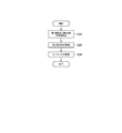
- FIG. 11 is a flowchart showing a method for manufacturing the non-burning type flavor inhaler member according to the second embodiment.
- the non-combustion type flavor inhaler is generated by an atomization unit that atomizes an aerosol source without combustion, a flavor source that is provided on the suction side of the atomization unit, and the atomization unit.
- the aerosol flow path includes a first flow path for guiding the aerosol to the mouthpiece side through the flavor source, and a second flow path different from the first flow path.
- the aerosol reduction rate in the second flow path is smaller than the aerosol reduction rate in the first flow path.
- a second flow path different from the first flow path that guides the aerosol to the mouthpiece side through the flavor source is provided, and the aerosol reduction rate in the second flow path is the aerosol reduction rate in the first flow path. Less than the reduction rate. Thereby, the shortage of aerosol can be efficiently compensated for by the aerosol passing through the second flow path while taking out a desired amount of flavor components from the flavor source by the aerosol passing through the first flow path. Therefore, it is possible to reduce the consumption of the aerosol source and the loss of the energy amount necessary for atomization.
- FIG. 1 is a view showing a non-burning type flavor inhaler 100 according to the first embodiment.
- the non-combustion type flavor inhaler 100 is an instrument for sucking flavor components without combustion, and has a shape extending along a predetermined direction A that is a direction from the non-suction end toward the suction end.
- the non-burning type flavor inhaler 100 is simply referred to as the flavor inhaler 100.
- the flavor suction device 100 includes a suction device main body 110, a suction member 120, and a cartridge 130.
- the suction unit main body 110 constitutes the main body of the flavor suction unit 100 and has a shape to which the cartridge 130 can be connected.
- the aspirator body 110 includes an atomization unit 111 that atomizes an aerosol source without combustion.
- the atomization unit 111 includes a reservoir 111P, a wick 111Q, and an atomization unit 111R.
- the reservoir 111P holds an aerosol source.
- the reservoir 111P is a porous body made of a non-tobacco material such as a resin web.
- the wick 111Q sucks up the aerosol source held in the reservoir 111P.
- the wick 111Q is made of glass fiber.
- the atomization unit 111R atomizes the aerosol source sucked up by the wick 111Q.
- the atomizing unit 111R is configured by, for example, a heating wire wound around the wick 111Q at a predetermined pitch.
- the aerosol source is a liquid such as glycerin or propylene glycol.
- the aerosol source is held by a porous body made of a non-tobacco material such as a resin web.
- the aerosol source may include a flavor source containing a nicotine component or the like.
- the aerosol source may not include a flavor source containing a nicotine component or the like.
- the aerosol source may include a flavor source containing components other than the nicotine component.
- the aerosol source may not include a flavor source that includes components other than the nicotine component.
- the atomizing unit 111 a heating type unit that atomizes an aerosol source by heating is illustrated.
- the atomization unit 111 may be an ultrasonic type unit that atomizes an aerosol source by ultrasonic waves.
- the suction member 120 has a suction mouth that can be received by the user, and is configured to be detachable from the suction device main body 110.
- the suction member 120 is attached to the aspirator body 110 by, for example, screwing or fitting.
- the cartridge 130 is an example of a flavor source unit configured to be connectable to the aspirator body 110 constituting the flavor inhaler 100.
- the cartridge 130 is provided on the suction side of the atomization unit 111 on the flow path of gas (hereinafter, air) sucked from the suction port.
- air gas
- the cartridge 130 does not necessarily have to be physically provided on the suction side of the atomization unit 111 in terms of physical space, and the atomization unit 111 on the aerosol flow path that guides the aerosol generated by the atomization unit 111 to the suction side. What is necessary is just to be provided in the inlet side rather than. That is, in the first embodiment, the “suction side” may be considered as synonymous with “downstream” of the aerosol flow, and the “non-suction side” is synonymous with “upstream” of the aerosol flow. You may think.
- the cartridge 130 includes a cartridge main body 131, a flavor source 132, and a mesh 133 (mesh 133A and mesh 133B).
- the cartridge body 131 has a cylindrical shape extending along the predetermined direction A.
- the cartridge body 131 accommodates the flavor source 132.
- the flavor source 132 is provided on the suction side of the atomization unit 111 on the flow path of the air sucked from the suction port.
- the flavor source 132 imparts a flavor component to the aerosol generated from the aerosol source. In other words, the flavor imparted to the aerosol by the flavor source 132 is carried to the mouthpiece.
- the flavor source 132 is constituted by a raw material piece that imparts a flavor component to the aerosol generated by the atomization unit 111.
- the size of the raw material piece is preferably 0.2 mm or more and 1.2 mm or less. Furthermore, the size of the raw material pieces is preferably 0.2 mm or more and 0.7 mm or less. Since the specific surface area increases as the size of the raw material piece constituting the flavor source 132 is smaller, the flavor component is easily released from the raw material piece constituting the flavor source 132. Therefore, the amount of the raw material pieces can be suppressed when applying the desired amount of flavor component to the aerosol.
- molded the cut tobacco and the tobacco raw material in the granule can be used as a raw material piece which comprises the flavor source 132.
- the flavor source 132 may be a molded body obtained by molding a tobacco material into a sheet shape.
- the raw material piece which comprises the flavor source 132 may be comprised by plants (for example, mint, an herb, etc.) other than tobacco.
- the flavor source 132 may be provided with a fragrance such as menthol.
- the raw material piece constituting the flavor source 132 is obtained, for example, by sieving in accordance with JIS Z 8815 using a stainless steel sieve in accordance with JIS Z 8801.
- a stainless steel sieve having an opening of 0.71 mm the raw material pieces are screened for 20 minutes by a dry and mechanical shaking method, and then passed through a stainless steel sieve having an opening of 0.71 mm. Get raw material pieces.
- a stainless steel sieve having an opening of 0.212 mm the raw material pieces are sieved for 20 minutes by a dry and mechanical shaking method, and then passed through a stainless steel sieve having an opening of 0.212 mm. Remove raw material pieces.
- the flavor source 132 is a tobacco source having an alkaline pH.
- the pH of the tobacco source is preferably greater than 7, more preferably 8 or more.
- the flavor component generated from the tobacco source can be efficiently taken out by the aerosol.
- the pH of the tobacco source is preferably 14 or less, and more preferably 10 or less. Thereby, damage (corrosion etc.) to the flavor suction device 100 (for example, the cartridge 130 or the suction device main body 110) can be suppressed.
- flavor component generated from the flavor source 132 is conveyed by aerosol, and it is not necessary to heat the flavor source 132 itself.
- the mesh 133A is provided so as to close the opening of the cartridge main body 131 on the non-suction side with respect to the flavor source 132
- the mesh 133B is configured to close the opening of the cartridge main body 131 on the suction side with respect to the flavor source 132.
- the mesh 133A and the mesh 133B have such a roughness that the raw material pieces constituting the flavor source 132 do not pass through.
- the roughness of the mesh 133A and the mesh 133B has a mesh opening of 0.077 mm or more and 0.198 mm or less, for example.
- FIG. 2 is a view for explaining the aerosol flow path according to the first embodiment. Specifically, FIG. 2 is a schematic cross-sectional view showing the internal structure of the flavor suction device 100 in a state where the cartridge 130 is accommodated in the suction device main body 110.
- the flavor inhaler 100 has an aerosol flow path 140 that guides the aerosol generated by the atomization unit 111 to the inlet side.
- the aerosol flow path 140 includes a first flow path 140A that guides the aerosol to the inlet side through the flavor source 132, and a second flow path 140B that is different from the first flow path 140A.
- the aerosol reduction rate in the second channel 140B is smaller than the aerosol reduction rate in the first channel 140A.
- the amount of aerosol guided to the inlet side through the second channel 140B is preferably equal to or greater than the amount of aerosol guided to the inlet side through the first channel 140A.
- the “reduction rate” is the ratio of the “aerosol amount lost in the flow path (inflow amount ⁇ outflow amount)” to the “aerosol amount flowing into the flow path (inflow amount)” (that is, (inflow amount ⁇ outflow amount). Volume) / inflow volume).
- the second flow path 140B is a flow path that guides the aerosol to the suction side without passing through the flavor source 132.
- the second flow path 140B is substantially hollow.
- the outer diameter of the cartridge main body 131 is smaller than the inner diameter of the aspirator main body 110 in a vertical cross section with respect to the predetermined direction A.
- the second flow path 140B is formed between the outer surface 131A of the cartridge main body 131 and the inner surface 110A of the suction device main body 110. Further, a branching portion 145 between the first flow path 140 ⁇ / b> A and the second flow path 140 ⁇ / b> B is provided outside the cartridge body 131.
- the first flow path 140A is provided in the cartridge main body 131, and the second flow path 140B is provided outside the cartridge main body 131.
- the first flow path 140A and the second flow path 140B have a common flow path that is common to each other.
- the branch portion 145 described above is provided in a common flow path formed between the atomization unit 111 and the cartridge 130. Two or more common portions may be provided. In other words, the first flow path 140A and the second flow path 140B may merge or branch at two or more locations.
- At least a part of the first flow path 140A is formed by the aspirator body 110 and the cartridge body 131.
- At least a part of the second flow path 140B is formed by the aspirator body 110 and the cartridge body 131.
- a second flow path 140B different from the first flow path 140A that guides the aerosol to the suction side through the flavor source 132 is provided, and the aerosol reduction rate in the second flow path 140B is It is smaller than the reduction rate of aerosol in one flow path 140A.
- the shortage of aerosol can be efficiently compensated for by the aerosol passing through the second flow path 140B while taking out a desired amount of flavor components from the flavor source 132 by the aerosol passing through the first flow path 140A. Therefore, it is possible to reduce the consumption of the aerosol source and the loss of the energy amount necessary for atomization.
- the second flow path 140B is a flow path that guides the aerosol to the inlet side without passing through the flavor source 132. Accordingly, since the aerosol is not filtered by the flavor source 132 in the second flow path 140B, the reduction of the aerosol in the second flow path 140B is suppressed, and the shortage of aerosol can be compensated efficiently. In addition, an event that promotes deterioration of the flavor source 132 due to the aerosol passing through the second flow path 140B is suppressed, and loss of consumption of the aerosol source can be reduced.
- the second flow path 140B is substantially hollow. Therefore, the reduction of the aerosol in the second flow path 140B is further suppressed, and the shortage of aerosol can be effectively compensated.
- the flavor source 132 is a tobacco source having an alkaline pH. Therefore, the flavor component generated from the tobacco source can be efficiently taken out by the aerosol. Since the flavor component can be taken out efficiently, the amount of tobacco source can be suppressed in obtaining a desired amount of the flavor component.
- the amount of aerosol guided to the suction side through the second flow path 140B is equal to or more than the amount of aerosol guided to the suction side through the first flow path 140A. Therefore, sufficient aerosol can be guided to the mouthpiece side while suppressing the deterioration of the flavor source 132.
- the flavor source 132 is constituted by a raw material piece that imparts a flavor component to the aerosol generated by the atomization unit 111.
- the specific surface area is increased as compared with a molded body obtained by molding a tobacco raw material into a sheet shape or a cut shape, so that the flavor component is easily released from the raw material piece constituting the flavor source 132. Therefore, when the desired amount of flavor component is applied to the aerosol by the flavor source 132, the volume of the raw material pieces constituting the flavor source 132 can be suppressed, and the member (here, the cartridge main body 131) that contains the flavor source 132 can be suppressed. ) Size can be suppressed.
- the flavor source 132 is likely to deteriorate.
- the second flow path 140B different from the first flow path 140A for guiding the aerosol to the side deterioration of the flavor source 132 is suppressed. That is, a member that contains the flavor source 132 by suppressing the volume of the raw material piece constituting the flavor source 132 while suppressing deterioration of the flavor source 132 by adopting the raw material piece having a large specific surface area and the second flow path 140B.
- the size of the cartridge main body 131 can be suppressed.
- FIG. 3 is a schematic cross-sectional view showing the internal structure of the flavor suction device 100 in a state where the cartridge 130 is accommodated in the suction device main body 110.
- differences from the first embodiment will be mainly described.
- the flavor inhaler 100 has a single unit as the atomization unit 111 that atomizes the aerosol source without combustion.
- the flavor inhaler 100 uses the aerosol guided to the first flow path 140A as an atomization unit 111 that atomizes the aerosol source without combustion. It has the 1st atomization unit 111A which generate
- the first flow path 140A and the second flow path 140B are partitioned by the partition portion 110D provided in the suction unit main body 110, and thus the first flow path 140A and the second flow path 140B are separated.
- the branching portion 145 may not be particularly provided.
- FIG. 3 only an example is shown about arrangement
- the aerosol source from which the first atomizing unit 111A atomizes may be different from the aerosol source from which the second atomizing unit 111B atomizes.
- the aerosol source from which the first atomizing unit 111A atomizes is composed of a substance that generates an aerosol that easily extracts the flavor components from the flavor source 132, and the aerosol source from which the second atomizing unit 111B atomizes is the aerosol source.
- the substance may generate an aerosol containing a fragrance.
- the aerosol source from which the first atomizing unit 111A atomizes may be the same as the aerosol source from which the second atomizing unit 111B atomizes.
- the first flow path 140A is mainly formed by the cartridge body 131.
- the second flow path 140B is formed by the aspirator body 110.
- the flavor inhaler 100 includes an atomizing unit 111 that atomizes an aerosol source without combustion, and a first atomizing unit 111A that generates aerosol guided to the first flow path 140A and a second flow. It has the 2nd atomization unit 111B which generate
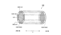
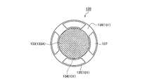
- FIGS. 4 to 6 are perspective views of the cartridge 130 according to the second modification
- FIG. 5 is a view of the cartridge 130 according to the second modification when viewed from the suction side
- FIG. 6 is a schematic cross-sectional view showing the internal structure of the flavor suction device 100 in a state where the cartridge 130 is accommodated in the suction device main body 110.
- differences from the first embodiment will be mainly described.
- the second flow path 140B is formed between the outer surface 131A of the cartridge body 131 and the inner surface 110A of the suction device body 110.
- both the first flow path 140A and the second flow path 140B are formed in the cartridge main body 131.
- the first flow path 140A formed in the cartridge main body 131 and the second flow path 140B formed in the cartridge main body 131 are formed independently so as not to cross each other.
- the cartridge 130 includes an inner body 134, an outer body 135, and a rib 136 as the cartridge main body 131 described above. It should be noted that the flavor source 132 described above is omitted in FIG.
- the inner body 134 has a cylindrical shape extending along the predetermined direction A.
- the inner body 134 houses the flavor source 132.
- a mesh 133 ⁇ / b> A is provided on the non-suction side of the inner body 134, and a mesh 133 ⁇ / b> B is provided on the suction side of the inner body 134.
- the outer body 135 has a cylindrical shape extending along the predetermined direction A.
- the outer body 135 accommodates the inner body 134.
- the outer body 135 is fixed to the inner body 134 by ribs 136 extending along a predetermined direction A.
- the outer body 135 is fixed to the inner body 134 by four ribs 136, and a gap 137 extending along the predetermined direction A is formed between the ribs 136 adjacent to each other.
- the first flow path 140A described above is a flow path passing through the inside of the inner body 134
- the second flow path 140B described above is A flow path passing through the gap 137.
- the cartridge body 131 is configured by the inner body 134, the outer body 135, and the rib 136 is illustrated.
- the modified example 2 is not limited to this. It should be noted that various modifications can be made as long as both the first flow path 140A and the second flow path 140B are formed in the cartridge body 131.
- both the first flow path 140A and the second flow path 140B are mainly formed in the cartridge body 131, and the branching portion 145 between the first flow path 140A and the second flow path 140B is Similar to the first embodiment, it is provided outside the cartridge body 131.
- the first flow path 140A and the second flow path 140B have a common flow path that is common to each other.
- the branch portion 145 described above is provided in a common flow path formed between the atomization unit 111 and the cartridge 130. Two or more common portions may be provided. In other words, the first flow path 140A and the second flow path 140B may merge or branch at two or more locations.
- At least a part of the first flow path 140A is formed by the aspirator body 110 and the cartridge body 131.
- At least a part of the second flow path 140B is formed by the aspirator body 110 and the cartridge body 131.
- the first flow path 140 ⁇ / b> A and the second flow path 140 ⁇ / b> B are formed in the cartridge main body 131. Therefore, the second flow path 140B can be formed without changing the design of the aspirator body 110.
- first flow path 140A and the second flow path 140B can be appropriately formed only by changing the shape of the cartridge 130 according to the type of the flavor source 132.
- the aspirator body 110 that is continuously used is not easily contaminated by the aerosol flow.
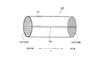
- FIG. 7 is a perspective view of the cartridge 130 according to Modification Example 3
- FIG. 8 is a view of the cartridge 130 according to Modification Example 3 as viewed from the inlet side.
- FIG. 9 is a schematic cross-sectional view showing the internal structure of the flavor suction device 100 in a state where the cartridge 130 is accommodated in the suction device main body 110.
- the outer diameter of the cartridge body 131 is smaller than the inner diameter of the aspirator body 110 in the vertical cross section with respect to the predetermined direction A.
- the outer surface 131A of the cartridge main body 131 other than the groove 138 is in contact with the inner surface 110A of the suction device main body 110 in the vertical cross section with respect to the predetermined direction A.
- the outer surface 131A of the cartridge main body 131 extends along the predetermined direction A from the non-suction end to the suction end, and is formed with a groove that opens at least to the suction end. A part of the two flow paths 140B is formed.
- the outer surface 131 ⁇ / b> A of the cartridge body 131 is formed with a groove 138 that continues from the non-suction end of the cartridge body 131 to the suction end of the cartridge body 131 in the predetermined direction A.
- four grooves 138 extending along the predetermined direction A are illustrated.
- the groove 138 may be a linear groove or a groove including a curve.
- the first flow path 140A described above is a flow path passing through the inside of the cartridge main body 131
- the second flow path 140B described above is A flow path through the groove 138. That is, the second flow path 140B described above is formed by the inner surface 110A of the suction device main body 110 and the groove 138 of the cartridge main body 131. In other words, the groove 138 forms a part of the second flow path 140B.
- the modified example 3 is not limited to this. Even in a case where the outer diameter of the cartridge main body 131 is smaller than the inner diameter of the suction device main body 110 in the vertical cross section with respect to the predetermined direction A, the groove 138 may be formed on the outer surface 131A of the cartridge main body 131.
- the first flow path 140A and the second flow path 140B are partitioned by the outer wall of the cartridge body 131. Accordingly, the first flow path 140A formed in the cartridge main body 131 and the second flow path 140B formed in the cartridge main body 131 are formed independently so as not to cross each other.
- the first flow path 140A and the second flow path 140B have a common flow path that is common to each other.
- the branch portion 145 described above is provided in a common flow path formed between the atomization unit 111 and the cartridge 130. Two or more common portions may be provided. In other words, the first flow path 140A and the second flow path 140B may merge or branch at two or more locations.
- At least a part of the first flow path 140A is formed by the aspirator body 110 and the cartridge body 131.
- At least a part of the second flow path 140B is formed by the aspirator body 110 and the cartridge body 131.
- a groove 138 extending along a predetermined direction A from the non-suction end to the suction end is formed on the outer surface 131A of the cartridge body 131, and the groove 138 forms a part of the second flow path 140B. Form. Therefore, the second flow path 140B can be formed without changing the design of the aspirator body 110.
- a part of the second flow path 140B is formed by the inner surface 110A of the suction unit main body 110.
- a part of the member (outer body 135) forming the second flow path 140B is replaced by the inner surface 110A of the suction device main body 110. Is done. Therefore, when compared with the second modification, the space for storing the flavor source 132 can be expanded outward by an amount corresponding to the thickness of the member (outer body 135) replaced by the inner surface 110A of the suction device main body 110. Yes, the volume capable of accommodating the flavor source 132 increases.
- the second flow path 140B can be easily cleaned when the second flow path 140B constituted by the groove 138 is clogged.
- FIG. 10 is a schematic cross-sectional view showing the internal structure of the flavor suction device 100 in a state where the cartridge 130 is accommodated in the suction device main body 110. In the following, differences from the first embodiment will be mainly described.
- the branching portion 145 between the first flow path 140A and the second flow path 140B is provided outside the cartridge body 131.
- the branch portion 145 between the first flow path 140A and the second flow path 140B is provided in the cartridge main body 131 as shown in FIG.
- the second flow path 140B downstream from the branch portion 145 extends from the inside of the cartridge body 131 to the outside of the cartridge body 131 via the opening 139 provided in the side wall of the cartridge body 131.
- a part of the hollow second flow path 140B is formed by the outer surface 131A of the cartridge main body 131 and the inner surface 110A of the suction device main body 110.
- the aerosol is filtered and reduced by the flavor source in the first flow path 140A even downstream of the branch portion 145. Therefore, it should be noted that even when the branch portion 145 is provided in the cartridge body 131, the aerosol reduction rate in the second flow path 140B is smaller than the aerosol reduction rate in the first flow path 140A. is there.
- the cartridge 130 has a mesh 133C provided so as to close the opening 139.
- the mesh 133C has such a roughness that the raw material pieces constituting the flavor source 132 do not pass through.
- the roughness of the mesh 133C has, for example, an opening of 0.077 mm or more and 0.198 mm or less, similar to the mesh 133A and the mesh 133B.
- the mesh 133C may not be provided.
- the non-suction side end (upstream end) of the cartridge 130 is in contact with the suction side end (downstream end) of the atomization unit 111. Accordingly, since all of the aerosol output from the atomization unit 111 is guided to the cartridge 130, the aerosol output from the atomization unit 111 does not enter the cartridge 130 and is not guided to the second flow path 140B.
- both the first flow path 140A and the second flow path 140B may be formed in the cartridge body 131 as in the modification example 2.
- a groove extending along a predetermined direction A from the non-suction end to the suction end may be formed on the outer surface 131A of the cartridge body 131. Good.
- the groove is continuous at least from the opening 139 to the suction end of the cartridge main body 131, and may be open to the suction end.
- the groove may be continuous from the non-suction end of the cartridge body 131 to the suction end of the cartridge body 131.
- the first flow path 140A and the second flow path 140B have a common flow path that is common to each other.
- the branch portion 145 described above is provided in a common flow path formed in the cartridge main body 131. Two or more common portions may be provided. In other words, the first flow path 140A and the second flow path 140B may merge or branch at two or more locations.
- the first flow path 140A is formed by the cartridge body 131. At least a part of the second flow path 140B is formed by the aspirator body 110 and the cartridge body 131.
- a branch portion 145 between the first flow path 140 ⁇ / b> A and the second flow path 140 ⁇ / b> B is provided in the cartridge main body 131. Therefore, the second flow path 140B can be formed without changing the design of the aspirator body 110.
- FIG. 11 is a flowchart showing a method for manufacturing the non-burning type flavor inhaler member according to the second embodiment.
- the non-combustion type flavor inhaler member is an aerosol flow path forming member that forms at least a part of the aerosol flow path 140 (the first flow path 140A and the second flow path 140B).
- the shapes of the first flow path 140A and the second flow path 140B are determined. Specifically, as described later, the shapes of the first flow path 140A and the second flow path 140B are such that the air distributed to the second flow path 140B passes through the second flow path 140B and the second flow path 140B. Is determined so that the air distributed to the first flow path 140A passes through the first flow path 140A and becomes the same as the ventilation resistance generated in the first flow path 140A.
- the shape of the second flow path 140B is preferably determined based on the shape of the first flow path 140A and the flow rate of air flowing into the first flow path 140A. Furthermore, it is preferable that the flow rate of the air flowing into the first flow path 140 ⁇ / b> A is determined based on the amount of aerosol necessary for extracting a desired amount of flavor components from the flavor source 132.
- the aerosol amount necessary for taking out a desired amount of flavor ingredient is calculated based on at least one of the type, size and filling amount of the constituent material of the raw material pieces constituting the flavor source 132. It should also be noted that the desired amount of aerosol to be directed to the mouthpiece side varies with the amount of aerosol that is filtered by the flavor source 132.
- the amount of aerosol that is filtered by the flavor source 132 is the channel size and length of the first channel 140A, the length of the portion of the first channel 140A that is filled with the flavor source 132, and the flavor source 132. It can also be calculated based on parameters such as the type, size, and filling amount of the constituent material of the raw material piece.
- step S20 the aspirator body 110 described above is manufactured. It should be noted that step S20 is performed based on the determination result of the shape of the first flow path 140A and the second flow path 140B in step S10.
- step S30 the cartridge 130 described above is manufactured. It should be noted that step S30 is performed based on the determination result of the shape of the first flow path 140A and the second flow path 140B in step 10.
- the method for manufacturing the non-combustion type flavor inhaler member includes the step A for manufacturing the aerosol flow path forming member that forms at least a part of the aerosol flow path, and the step A is distributed to the second flow path 140B.
- the airflow resistance generated in the second flow path 140B by the air being passed through the second flow path 140B is the same as that in the first flow path 140A due to the air distributed to the first flow path 140A passing through the first flow path 140A.
- the step of determining the shapes of the first flow path 140A and the second flow path 140B so as to be the same as the generated airflow resistance is included.
- the manufacturing method includes steps S10 to S30.
- the embodiment is not limited to this.
- the manufacturing method (step A) may include steps S10 and S20.
- a manufacturing method (step A) should just include step S10 and step S30.
- the first flow path 140A and the second flow path 140B are formed by both the aspirator body 110 and the cartridge 130. However, the first flow path 140A and the second flow path 140B may be formed only by the cartridge 130.
- the amount of aerosol M T [mg / puff] generated by the atomization unit 111 is determined.
- the parameter is, for example, at least one of the type, size, and filling amount of the constituent material of the raw material piece constituting the flavor source 132.
- the aerosol amount M 1 necessary for taking out a desired amount of flavor components from the flavor source 132 is determined based on the parameters relating to the flavor source 132.
- the shape of the first flow path 140A is determined. Specifically, all of the raw material pieces having a predetermined parameter (that is, the flavor source 132 is configured based on at least one parameter of the type, size, and filling amount of the constituent material of the raw material pieces constituting the flavor source 132. The shape of the first flow path 140A is determined so that all of the raw material pieces to be stored in the first flow path 140A.
- the flow rate Q 1 of air distributed to the first flow path 140A (ie, the flow rate of air passing through the flavor source 132)
- Q 1) seek.
- a ventilation resistance ⁇ P 1 [Pa] generated at the flavor source 132 when the air having the air flow rate Q 1 passes through the flavor source 132 is calculated.
- the value of ventilation resistance when the air flow rate is variously changed by experiment can be measured, and ⁇ P 1 in Q 1 can be estimated based on the regression equation obtained from the obtained plot.
- the ventilation resistance is based on the known theoretical equation or empirical equation for flow resistance of the flavor source packed layer may estimate [Delta] P 1 in Q 1.
- ⁇ P 2 32 ⁇ ⁇ ⁇ L ⁇ u / D 2
- ⁇ Kinematic viscosity coefficient [Pa ⁇ s] of air
- L Length of second flow path [m]
- u Average flow velocity [m / s] in second flow path
- D Second flow path Diameter [m]
- the case where the gas distributed to the first flow path 140A or the second flow path 140B is air is exemplified, but the gas distributed to the first flow path 140A or the second flow path 140B is exemplified. May be a gas other than air.
- the manufacturing method of the member for non-combustion type flavor inhalers manufactures the aerosol flow path formation member which forms at least one part of the aerosol flow path 140 which guides the aerosol generated by the atomization unit 111 to the suction side.
- Step A (step S10 to step S30 in the second embodiment) is included.
- the air flow resistance generated in the first flow path 140A when the air distributed to the first flow path 140A passes through the first flow path 140A is the same as the air flow distributed to the second flow path 140B.
- the step of determining the shapes of the first flow path 140A and the second flow path 140B so as to be the same as the ventilation resistance generated in the second flow path 140B by passing through 140B is included.
- the first flow path 140A for taking out a desired amount of flavor components from the flavor source 132 and the second flow path 140B for compensating for the shortage of aerosol can be appropriately formed. Accordingly, an event that promotes deterioration of the flavor source 132 due to the aerosol passing through the second flow path 140B is suppressed, and loss of consumption of the aerosol source can be reduced.
- Step A includes a step of determining the shape of the second flow path 140B based on the shape of the first flow path 140A and the flow rate of air flowing into the first flow path 140A. Therefore, it is easy to determine the shape of the second flow path 140B for compensating for the shortage of aerosol.
- step A determines the flow rate of the air flowing into the first flow path 140A based on the amount of aerosol necessary for extracting a desired amount of flavor components from the flavor source. Therefore, it is possible to take out a desired amount of flavor components while compensating for the shortage of aerosol.
- step A is the amount of aerosol required in order to take out a desired quantity of flavor components from a flavor source, and is at least any one of the kind of constituent material of the raw material piece which comprises a flavor source, a size, and a filling amount. Determining based on one. Therefore, it is possible to appropriately determine the amount of aerosol necessary for taking out a desired amount of flavor ingredient.
- step A includes a step of determining the shape of the first flow path 140A so as to accommodate all the raw material pieces constituting the flavor source. Therefore, the shape of the first flow path 140A for taking out a desired amount of the flavor component can be appropriately determined.
- the cartridge 130 does not include the atomization unit, but the embodiment is not limited thereto.
- the cartridge 130 may constitute one unit together with the atomization unit.
- the flavor source 132 is included in the cartridge 130 configured to be connectable to the aspirator body 110 constituting the flavor inhaler 100.
- the embodiment is not limited to this.
- the aspirator body 110 may accommodate the flavor source 132 without using the cartridge 130.
- the embodiment a case in which the second flow path 140B is provided in the cartridge 130 (first embodiment, modified example 1, modified example 3), and a case in which the second flow path 140B is provided outside the cartridge 130 (modified example 2).
- the case (Modification 4) provided outside the cartridge 130 after the second flow path 140B branches in the cartridge 130 has been described.
- the embodiment is not limited to this. Specifically, it is sufficient that the aerosol reduction rate in the second flow path 140B is smaller than the aerosol reduction rate in the first flow path 140A, and the second flow path 140B moves the cartridge 130 toward the downstream of the aerosol flow path.
- the number of times to enter and exit is not limited.
- the outer periphery of the cartridge body 131 and the inner periphery of the suction device body 110 have a circular shape.
- the embodiment is not limited to this.
- the outer periphery of the cartridge main body 131 and the inner periphery of the suction device main body 110 may have other shapes (for example, a square shape).
- the consumption of the aerosol source and the loss of the amount of energy required for atomization can be reduced, the non-burning type flavor inhaler, the flavor source unit, and the method for producing the non-burning type flavor inhaler member Can be provided.
Priority Applications (8)
| Application Number | Priority Date | Filing Date | Title |
|---|---|---|---|
| EA201791704A EA035032B1 (ru) | 2015-01-26 | 2015-06-04 | Ингалятор аромата несжигающего типа и способ его изготовления |
| AU2015379291A AU2015379291B2 (en) | 2015-01-26 | 2015-06-04 | Non-combustion type flavor inhaler, flavor source unit, and method for manufacturing member used in a non-combustion type flavor inhaler |
| JP2016571660A JP6511073B2 (ja) | 2015-01-26 | 2015-06-04 | 非燃焼型香味吸引器、香味源ユニット及び非燃焼型香味吸引器用部材の製造方法 |
| EP15880037.5A EP3245885B1 (en) | 2015-01-26 | 2015-06-04 | Non-combustion type flavor inhaler, flavor source unit, and method for manufacturing member used in a non-combustion type flavor inhaler |
| CN201580074327.6A CN107205482B (zh) | 2015-01-26 | 2015-06-04 | 非燃烧型香味吸取器、香味源单元以及非燃烧型香味吸取器用部件的制造方法 |
| KR1020177019002A KR101983485B1 (ko) | 2015-01-26 | 2015-06-04 | 비연소형 향미 흡인기, 향미원 유닛 및 비연소형 향미 흡인기용 부재의 제조 방법 |
| US15/657,504 US10828435B2 (en) | 2015-01-26 | 2017-07-24 | Non-combustion type flavor inhaler, flavor source unit, and method for manufacturing member used in a non-combustion type flavor inhaler |
| HK18103978.0A HK1244638A1 (zh) | 2015-01-26 | 2018-03-22 | 非燃燒型香味吸取器、香味源單元以及非燃燒型香味吸取器用部件的製造方法 |
Applications Claiming Priority (2)
| Application Number | Priority Date | Filing Date | Title |
|---|---|---|---|
| JPPCT/JP2015/052063 | 2015-01-26 | ||
| JP2015052063 | 2015-01-26 |
Related Child Applications (1)
| Application Number | Title | Priority Date | Filing Date |
|---|---|---|---|
| US15/657,504 Continuation US10828435B2 (en) | 2015-01-26 | 2017-07-24 | Non-combustion type flavor inhaler, flavor source unit, and method for manufacturing member used in a non-combustion type flavor inhaler |
Publications (1)
| Publication Number | Publication Date |
|---|---|
| WO2016121143A1 true WO2016121143A1 (ja) | 2016-08-04 |
Family
ID=56542784
Family Applications (1)
| Application Number | Title | Priority Date | Filing Date |
|---|---|---|---|
| PCT/JP2015/066258 WO2016121143A1 (ja) | 2015-01-26 | 2015-06-04 | 非燃焼型香味吸引器、香味源ユニット及び非燃焼型香味吸引器用部材の製造方法 |
Country Status (11)
| Country | Link |
|---|---|
| US (1) | US10828435B2 (ru) |
| EP (1) | EP3245885B1 (ru) |
| JP (2) | JP6511073B2 (ru) |
| KR (1) | KR101983485B1 (ru) |
| CN (1) | CN107205482B (ru) |
| AU (1) | AU2015379291B2 (ru) |
| EA (1) | EA035032B1 (ru) |
| HK (1) | HK1244638A1 (ru) |
| MY (1) | MY181354A (ru) |
| TW (1) | TWI581724B (ru) |
| WO (1) | WO2016121143A1 (ru) |
Cited By (31)
| Publication number | Priority date | Publication date | Assignee | Title |
|---|---|---|---|---|
| WO2018037562A1 (ja) * | 2016-08-26 | 2018-03-01 | 日本たばこ産業株式会社 | 非燃焼型香味吸引器 |
| WO2018056300A1 (ja) * | 2016-09-26 | 2018-03-29 | 日本たばこ産業株式会社 | 香味吸引器 |
| WO2018114263A1 (en) * | 2016-12-19 | 2018-06-28 | Philip Morris Products S.A. | Aerosol-generating system having a cartridge with a side aperture |
| WO2018130391A1 (en) * | 2017-01-13 | 2018-07-19 | British American Tobacco (Investments) Limited | Aerosol generating device and article |
| KR20190055800A (ko) | 2016-10-04 | 2019-05-23 | 필립모리스 프로덕츠 에스.에이. | 불연성 흡연 장치 및 그의 요소 |
| KR20190089886A (ko) * | 2016-12-19 | 2019-07-31 | 필립모리스 프로덕츠 에스.에이. | 모듈형 조립체를 포함하는 에어로졸 발생 시스템 |
| JP2019528681A (ja) * | 2016-07-08 | 2019-10-17 | アール・エイ・アイ・ストラテジック・ホールディングス・インコーポレイテッド | 凝縮気化および非凝縮気化を用いたエアロゾル送達装置 |
| JP2019531085A (ja) * | 2016-11-14 | 2019-10-31 | 林 光榕 | 末広形状煙排出管を有する電子タバコアトマイザー |
| JP2020513193A (ja) * | 2017-04-12 | 2020-05-07 | ブリティッシュ アメリカン タバコ (インヴェストメンツ) リミテッドBritish American Tobacco (Investments) Limited | 喫煙材を揮発させるための装置及び喫煙品 |
| JP2020513743A (ja) * | 2017-01-05 | 2020-05-21 | ブリティッシュ アメリカン タバコ (インヴェストメンツ) リミテッドBritish American Tobacco (Investments) Limited | エアロゾル生成装置及びエアロゾル生成物品 |
| US10667553B2 (en) | 2013-01-24 | 2020-06-02 | Fontem Holdings 4 B.V. | Method, composition and apparatus for functionalization of aerosols from non combustible smoking articles |
| JP2021500048A (ja) * | 2017-10-24 | 2021-01-07 | ブリティッシュ アメリカン タバコ (インヴェストメンツ) リミテッドBritish American Tobacco (Investments) Limited | マウスピース集合体 |
| WO2021014832A1 (ja) * | 2019-07-19 | 2021-01-28 | 日本たばこ産業株式会社 | 香味ディスペンサー装置 |
| US11013264B2 (en) | 2014-11-19 | 2021-05-25 | Fontem Holdings 4 B.V. | Method, composition and apparatus for functionalization of aerosols from non combustible smoking articles |
| EP3694349B1 (de) * | 2017-10-13 | 2022-02-23 | Hauni Maschinenbau GmbH | Inhalator, insbesondere elektronisches zigarettenprodukt |
| US11298479B2 (en) | 2016-06-13 | 2022-04-12 | Nicoventures Trading Limited | Aerosol delivery device |
| CN114468360A (zh) * | 2016-12-16 | 2022-05-13 | 韩国烟草人参公社 | 气溶胶生成方法及装置 |
| US11439778B2 (en) | 2017-10-24 | 2022-09-13 | Nicoventures Trading Limited | Aerosol provision device with first and second side-by-side sections |
| JP2022540023A (ja) * | 2019-07-10 | 2022-09-14 | ニコベンチャーズ トレーディング リミテッド | 蒸気送達システム |
| US11511056B2 (en) | 2015-10-02 | 2022-11-29 | Nicoventures Trading Limited | Apparatus for generating an inhalable medium |
| US11596751B2 (en) | 2017-10-24 | 2023-03-07 | Nicoventures Trading Limited | Cartridge for an aerosol provision device |
| US11623053B2 (en) | 2017-12-06 | 2023-04-11 | Nicoventures Trading Limited | Component for an aerosol-generating apparatus |
| US11672276B2 (en) | 2016-11-02 | 2023-06-13 | British American Tobacco (Investments) Limited | Aerosol provision article |
| WO2023188375A1 (ja) * | 2022-03-31 | 2023-10-05 | 日本たばこ産業株式会社 | 霧化ユニット及びその製造方法、並びに吸引具 |
| WO2023188377A1 (ja) * | 2022-03-31 | 2023-10-05 | 日本たばこ産業株式会社 | 霧化ユニット及びその製造方法、並びに吸引具 |
| WO2023188374A1 (ja) * | 2022-03-31 | 2023-10-05 | 日本たばこ産業株式会社 | 霧化ユニット及びその製造方法、並びに吸引具 |
| WO2023188373A1 (ja) * | 2022-03-31 | 2023-10-05 | 日本たばこ産業株式会社 | 霧化ユニット及びその製造方法、並びに吸引具 |
| WO2023188376A1 (ja) * | 2022-03-31 | 2023-10-05 | 日本たばこ産業株式会社 | 霧化ユニット及びその製造方法、並びに吸引具 |
| WO2023188372A1 (ja) * | 2022-03-31 | 2023-10-05 | 日本たばこ産業株式会社 | 霧化ユニット及びその製造方法、並びに吸引具 |
| JP7375999B2 (ja) | 2019-07-10 | 2023-11-08 | ニコベンチャーズ トレーディング リミテッド | 蒸気送達システム |
| US11865246B2 (en) | 2015-02-27 | 2024-01-09 | Nicoventures Trading Limited | Apparatus for generating an inhalable medium |
Families Citing this family (18)
| Publication number | Priority date | Publication date | Assignee | Title |
|---|---|---|---|---|
| JP1554862S (ru) * | 2016-01-25 | 2016-07-25 | ||
| KR102311334B1 (ko) * | 2016-07-27 | 2021-10-08 | 니뽄 다바코 산교 가부시키가이샤 | 향미 흡인기, 카트리지 및 향미 유닛 |
| US10130124B2 (en) * | 2016-12-06 | 2018-11-20 | Shanghai Green Vaper Technology Co., Ltd. | Low temperature heat not burn electronic cigarette |
| EA202090952A1 (ru) * | 2017-10-24 | 2020-10-23 | Джапан Тобакко Инк. | Аэрозоль-генерирующее устройство |
| EA202190814A1 (ru) * | 2018-10-19 | 2021-08-26 | ДжейТи ИНТЕРНЕШНЛ СА | Система, генерирующая аэрозоль |
| CN113163858A (zh) * | 2018-11-27 | 2021-07-23 | 日本烟草产业株式会社 | 非燃烧型香味吸取器用的蒸汽生成单元的制造方法 |
| EP3911390B1 (en) * | 2019-01-14 | 2022-10-26 | Philip Morris Products, S.A. | Dry powder inhaler device, dry powder cartridge, and kit |
| GB201901652D0 (en) * | 2019-02-06 | 2019-03-27 | Nicoventures Trading Ltd | Vapour provision systems |
| CN113840548A (zh) * | 2019-05-17 | 2021-12-24 | 日本烟草产业株式会社 | 香味吸取器用的烟杆 |
| US10842189B1 (en) * | 2019-10-09 | 2020-11-24 | Cegnum LLC | Electronic smoking device including terminals arranged to provide for selective energizing of heating elements |
| KR102522674B1 (ko) * | 2020-07-21 | 2023-04-18 | 주식회사 케이티앤지 | 에어로졸 생성 장치 |
| KR102471108B1 (ko) * | 2020-08-06 | 2022-11-25 | 주식회사 케이티앤지 | 에어로졸 생성 장치 |
| KR102511597B1 (ko) * | 2020-09-07 | 2023-03-17 | 주식회사 케이티앤지 | 에어로졸 생성 장치 및 에어로졸 생성 장치에 사용되는 카트리지 |
| CN214103227U (zh) * | 2020-09-10 | 2021-09-03 | 深圳雾芯科技有限公司 | 一种雾化设备及电子烟 |
| KR102533274B1 (ko) * | 2020-11-24 | 2023-05-15 | 주식회사 케이티앤지 | 에어로졸 생성 장치 |
| CN112493547A (zh) * | 2020-12-07 | 2021-03-16 | 深圳麦克韦尔科技有限公司 | 电子雾化装置 |
| CN114304739A (zh) * | 2021-12-31 | 2022-04-12 | 深圳麦克韦尔科技有限公司 | 气溶胶口味调节装置及雾化装置 |
| CN115316477B (zh) * | 2022-07-18 | 2023-10-27 | 李博文 | 一种巧克力风味可吸食气溶胶制品的制作方法 |
Citations (5)
| Publication number | Priority date | Publication date | Assignee | Title |
|---|---|---|---|---|
| WO2013159245A1 (en) * | 2012-04-26 | 2013-10-31 | Ruyan Investment (Holdings) Limited | Electronic cigarette with sealed cartridge |
| WO2014104078A1 (ja) * | 2012-12-28 | 2014-07-03 | 日本たばこ産業株式会社 | 非燃焼吸引型たばこ製品用香味源及び非燃焼吸引型たばこ製品 |
| WO2014110119A1 (en) * | 2013-01-08 | 2014-07-17 | L. Perrigo Company | Electronic cigarette |
| WO2014115324A1 (ja) * | 2013-01-28 | 2014-07-31 | 日本たばこ産業株式会社 | 非加熱型香味吸引具 |
| JP2014528718A (ja) * | 2012-08-31 | 2014-10-30 | 劉 秋明LIU, Qiuming | 多種味電子タバコ |
Family Cites Families (11)
| Publication number | Priority date | Publication date | Assignee | Title |
|---|---|---|---|---|
| US20060191546A1 (en) * | 2003-04-01 | 2006-08-31 | Shusei Takano | Nicotine suction pipe and nicotine holder |
| US7726320B2 (en) | 2006-10-18 | 2010-06-01 | R. J. Reynolds Tobacco Company | Tobacco-containing smoking article |
| GB0808154D0 (en) * | 2008-05-06 | 2008-06-11 | British American Tobacco Co | Aerosol dispensing device |
| CN201379071Y (zh) * | 2008-12-18 | 2010-01-13 | 北京格林世界科技发展有限公司 | 一次性一体式电子雾化吸入器 |
| CN102395398B (zh) * | 2009-02-23 | 2016-03-16 | 日本烟草产业株式会社 | 非加热型烟草香味吸取器 |
| UA104557C2 (ru) * | 2010-08-24 | 2014-02-10 | Джапан Тобакко Інк. | Ингалятор аромата ненагревающего типа и способ изготовления ароматического картриджа для ингаляторов аромата ненагревающего типа |
| GB201203320D0 (en) * | 2012-02-27 | 2012-04-11 | British American Tobacco Co | A flow control device for a smoking article |
| TW201410163A (zh) * | 2012-07-19 | 2014-03-16 | Philip Morris Prod | 具有減少的側流煙之煙品 |
| CN103315405B (zh) * | 2013-07-17 | 2015-08-19 | 中国烟草总公司郑州烟草研究院 | 一种基于微波加热的非燃烧型烟草抽吸装置 |
| CN203884698U (zh) * | 2014-05-28 | 2014-10-22 | 深圳市瑞莱克斯科技有限公司 | 烘烤加热非燃烧型电子烟 |
| EP2989912B1 (en) * | 2014-09-01 | 2019-05-22 | Fontem Holdings 1 B.V. | Electronic smoking device |
-
2015
- 2015-06-04 CN CN201580074327.6A patent/CN107205482B/zh active Active
- 2015-06-04 AU AU2015379291A patent/AU2015379291B2/en active Active
- 2015-06-04 KR KR1020177019002A patent/KR101983485B1/ko active IP Right Grant
- 2015-06-04 MY MYPI2017702618A patent/MY181354A/en unknown
- 2015-06-04 EP EP15880037.5A patent/EP3245885B1/en active Active
- 2015-06-04 WO PCT/JP2015/066258 patent/WO2016121143A1/ja active Application Filing
- 2015-06-04 JP JP2016571660A patent/JP6511073B2/ja active Active
- 2015-06-04 EA EA201791704A patent/EA035032B1/ru not_active IP Right Cessation
- 2015-06-12 TW TW104119049A patent/TWI581724B/zh active
-
2017
- 2017-07-24 US US15/657,504 patent/US10828435B2/en active Active
-
2018
- 2018-03-22 HK HK18103978.0A patent/HK1244638A1/zh unknown
- 2018-12-21 JP JP2018239415A patent/JP6671451B2/ja active Active
Patent Citations (5)
| Publication number | Priority date | Publication date | Assignee | Title |
|---|---|---|---|---|
| WO2013159245A1 (en) * | 2012-04-26 | 2013-10-31 | Ruyan Investment (Holdings) Limited | Electronic cigarette with sealed cartridge |
| JP2014528718A (ja) * | 2012-08-31 | 2014-10-30 | 劉 秋明LIU, Qiuming | 多種味電子タバコ |
| WO2014104078A1 (ja) * | 2012-12-28 | 2014-07-03 | 日本たばこ産業株式会社 | 非燃焼吸引型たばこ製品用香味源及び非燃焼吸引型たばこ製品 |
| WO2014110119A1 (en) * | 2013-01-08 | 2014-07-17 | L. Perrigo Company | Electronic cigarette |
| WO2014115324A1 (ja) * | 2013-01-28 | 2014-07-31 | 日本たばこ産業株式会社 | 非加熱型香味吸引具 |
Non-Patent Citations (1)
| Title |
|---|
| See also references of EP3245885A4 * |
Cited By (72)
| Publication number | Priority date | Publication date | Assignee | Title |
|---|---|---|---|---|
| US10667553B2 (en) | 2013-01-24 | 2020-06-02 | Fontem Holdings 4 B.V. | Method, composition and apparatus for functionalization of aerosols from non combustible smoking articles |
| US11013264B2 (en) | 2014-11-19 | 2021-05-25 | Fontem Holdings 4 B.V. | Method, composition and apparatus for functionalization of aerosols from non combustible smoking articles |
| US11865246B2 (en) | 2015-02-27 | 2024-01-09 | Nicoventures Trading Limited | Apparatus for generating an inhalable medium |
| US11511056B2 (en) | 2015-10-02 | 2022-11-29 | Nicoventures Trading Limited | Apparatus for generating an inhalable medium |
| US11298479B2 (en) | 2016-06-13 | 2022-04-12 | Nicoventures Trading Limited | Aerosol delivery device |
| JP2019528681A (ja) * | 2016-07-08 | 2019-10-17 | アール・エイ・アイ・ストラテジック・ホールディングス・インコーポレイテッド | 凝縮気化および非凝縮気化を用いたエアロゾル送達装置 |
| JP7137553B2 (ja) | 2016-07-08 | 2022-09-14 | アール・エイ・アイ・ストラテジック・ホールディングス・インコーポレイテッド | 凝縮気化および非凝縮気化を用いたエアロゾル送達装置 |
| KR20190026929A (ko) * | 2016-08-26 | 2019-03-13 | 니뽄 다바코 산교 가부시키가이샤 | 비연소형 향미 흡인기 |
| KR102255848B1 (ko) * | 2016-08-26 | 2021-05-24 | 니뽄 다바코 산교 가부시키가이샤 | 비연소형 향미 흡인기 |
| CN109661182B (zh) * | 2016-08-26 | 2022-01-11 | 日本烟草产业株式会社 | 非燃烧型香味吸取器 |
| JPWO2018037562A1 (ja) * | 2016-08-26 | 2019-04-04 | 日本たばこ産業株式会社 | 非燃焼型香味吸引器 |
| EA038384B1 (ru) * | 2016-08-26 | 2021-08-19 | Джапан Тобакко Инк. | Негорючий ароматический ингалятор |
| CN109661182A (zh) * | 2016-08-26 | 2019-04-19 | 日本烟草产业株式会社 | 非燃烧型香味吸取器 |
| WO2018037562A1 (ja) * | 2016-08-26 | 2018-03-01 | 日本たばこ産業株式会社 | 非燃焼型香味吸引器 |
| KR20190052703A (ko) * | 2016-09-26 | 2019-05-16 | 니뽄 다바코 산교 가부시키가이샤 | 향미 흡인기 |
| JPWO2018056300A1 (ja) * | 2016-09-26 | 2019-07-18 | 日本たばこ産業株式会社 | 香味吸引器 |
| KR102277293B1 (ko) * | 2016-09-26 | 2021-07-13 | 니뽄 다바코 산교 가부시키가이샤 | 향미 흡인기 |
| CN109788804A (zh) * | 2016-09-26 | 2019-05-21 | 日本烟草产业株式会社 | 香味吸取器 |
| EP3513667A4 (en) * | 2016-09-26 | 2020-06-10 | Japan Tobacco Inc. | TASTE INHALATOR |
| WO2018055761A1 (ja) * | 2016-09-26 | 2018-03-29 | 日本たばこ産業株式会社 | 香味吸引器 |
| TWI679944B (zh) * | 2016-09-26 | 2019-12-21 | 日商日本煙草產業股份有限公司 | 香味吸嚐器 |
| EA039066B1 (ru) * | 2016-09-26 | 2021-11-29 | Джапан Тобакко Инк. | Ароматический ингалятор |
| WO2018056300A1 (ja) * | 2016-09-26 | 2018-03-29 | 日本たばこ産業株式会社 | 香味吸引器 |
| JP7194677B2 (ja) | 2016-10-04 | 2022-12-22 | フィリップ・モーリス・プロダクツ・ソシエテ・アノニム | 不燃性喫煙装置およびその要素 |
| JP2019531079A (ja) * | 2016-10-04 | 2019-10-31 | フィリップ・モーリス・プロダクツ・ソシエテ・アノニム | 不燃性喫煙装置およびその要素 |
| KR102578973B1 (ko) * | 2016-10-04 | 2023-09-15 | 필립모리스 프로덕츠 에스.에이. | 불연성 흡연 장치 및 그의 요소 |
| KR20190055800A (ko) | 2016-10-04 | 2019-05-23 | 필립모리스 프로덕츠 에스.에이. | 불연성 흡연 장치 및 그의 요소 |
| US11672276B2 (en) | 2016-11-02 | 2023-06-13 | British American Tobacco (Investments) Limited | Aerosol provision article |
| JP2019531085A (ja) * | 2016-11-14 | 2019-10-31 | 林 光榕 | 末広形状煙排出管を有する電子タバコアトマイザー |
| CN114468360A (zh) * | 2016-12-16 | 2022-05-13 | 韩国烟草人参公社 | 气溶胶生成方法及装置 |
| CN114468360B (zh) * | 2016-12-16 | 2023-12-22 | 韩国烟草人参公社 | 气溶胶生成方法及装置 |
| RU2756642C2 (ru) * | 2016-12-19 | 2021-10-04 | Филип Моррис Продактс С.А. | Система, генерирующая аэрозоль, содержащая картридж с боковым отверстием |
| CN110022704B (zh) * | 2016-12-19 | 2022-08-30 | 菲利普莫里斯生产公司 | 具有带侧孔口的筒的气溶胶生成系统 |
| WO2018114263A1 (en) * | 2016-12-19 | 2018-06-28 | Philip Morris Products S.A. | Aerosol-generating system having a cartridge with a side aperture |
| US10842954B2 (en) | 2016-12-19 | 2020-11-24 | Altria Client Services Llc | Aerosol-generating system having a cartridge with a side aperture |
| KR102590701B1 (ko) * | 2016-12-19 | 2023-10-18 | 필립모리스 프로덕츠 에스.에이. | 모듈형 조립체를 포함하는 에어로졸 발생 시스템 |
| CN110022704A (zh) * | 2016-12-19 | 2019-07-16 | 菲利普莫里斯生产公司 | 具有带侧孔口的筒的气溶胶生成系统 |
| KR102574019B1 (ko) | 2016-12-19 | 2023-09-04 | 필립모리스 프로덕츠 에스.에이. | 측면 애퍼쳐를 갖는 카트리지를 갖는 에어로졸 발생 시스템 |
| US11724048B2 (en) | 2016-12-19 | 2023-08-15 | Altria Client Services Llc | Aerosol-generating system having a cartridge with a side aperture |
| US11712062B2 (en) | 2016-12-19 | 2023-08-01 | Altria Client Services Llc | Aerosol-generating system comprising a modular assembly |
| KR20190089869A (ko) * | 2016-12-19 | 2019-07-31 | 필립모리스 프로덕츠 에스.에이. | 측면 애퍼쳐를 갖는 카트리지를 갖는 에어로졸 발생 시스템 |
| KR20190089886A (ko) * | 2016-12-19 | 2019-07-31 | 필립모리스 프로덕츠 에스.에이. | 모듈형 조립체를 포함하는 에어로졸 발생 시스템 |
| JP2020501555A (ja) * | 2016-12-19 | 2020-01-23 | フィリップ・モーリス・プロダクツ・ソシエテ・アノニム | 側面開口部を備えるカートリッジを有するエアロゾル発生システム |
| JP7080888B2 (ja) | 2016-12-19 | 2022-06-06 | フィリップ・モーリス・プロダクツ・ソシエテ・アノニム | 側面開口部を備えるカートリッジを有するエアロゾル発生システム |
| US11589617B2 (en) | 2017-01-05 | 2023-02-28 | Nicoventures Trading Limited | Aerosol generating device and article |
| JP2020513743A (ja) * | 2017-01-05 | 2020-05-21 | ブリティッシュ アメリカン タバコ (インヴェストメンツ) リミテッドBritish American Tobacco (Investments) Limited | エアロゾル生成装置及びエアロゾル生成物品 |
| JP2020503859A (ja) * | 2017-01-13 | 2020-02-06 | ブリティッシュ アメリカン タバコ (インヴェストメンツ) リミテッドBritish American Tobacco (Investments) Limited | エアロゾル生成装置及びエアロゾル生成物品 |
| WO2018130391A1 (en) * | 2017-01-13 | 2018-07-19 | British American Tobacco (Investments) Limited | Aerosol generating device and article |
| RU2729529C1 (ru) * | 2017-01-13 | 2020-08-07 | Бритиш Америкэн Тобэкко (Инвестментс) Лимитед | Устройство выработки аэрозоля и изделие для выработки аэрозоля |
| CN110167620A (zh) * | 2017-01-13 | 2019-08-23 | 英美烟草(投资)有限公司 | 气溶胶生成装置和制品 |
| KR20190097289A (ko) * | 2017-01-13 | 2019-08-20 | 브리티시 아메리칸 토바코 (인베스트먼츠) 리미티드 | 에어로졸 발생 디바이스 및 물품 |
| US11318264B2 (en) | 2017-01-13 | 2022-05-03 | Nicoventures Trading Limited | Aerosol generating device and article |
| KR102432843B1 (ko) * | 2017-01-13 | 2022-08-12 | 니코벤처스 트레이딩 리미티드 | 에어로졸 발생 디바이스 및 물품 |
| JP2020513193A (ja) * | 2017-04-12 | 2020-05-07 | ブリティッシュ アメリカン タバコ (インヴェストメンツ) リミテッドBritish American Tobacco (Investments) Limited | 喫煙材を揮発させるための装置及び喫煙品 |
| EP3694349B1 (de) * | 2017-10-13 | 2022-02-23 | Hauni Maschinenbau GmbH | Inhalator, insbesondere elektronisches zigarettenprodukt |
| US11439778B2 (en) | 2017-10-24 | 2022-09-13 | Nicoventures Trading Limited | Aerosol provision device with first and second side-by-side sections |
| JP2021500048A (ja) * | 2017-10-24 | 2021-01-07 | ブリティッシュ アメリカン タバコ (インヴェストメンツ) リミテッドBritish American Tobacco (Investments) Limited | マウスピース集合体 |
| RU2763680C2 (ru) * | 2017-10-24 | 2021-12-30 | Бритиш Америкэн Тобэкко (Инвестментс) Лимитед | Сборный мундштук |
| JP7092439B2 (ja) | 2017-10-24 | 2022-06-28 | ニコベンチャーズ トレーディング リミテッド | マウスピース集合体 |
| US11596751B2 (en) | 2017-10-24 | 2023-03-07 | Nicoventures Trading Limited | Cartridge for an aerosol provision device |
| US11623053B2 (en) | 2017-12-06 | 2023-04-11 | Nicoventures Trading Limited | Component for an aerosol-generating apparatus |
| JP7376000B2 (ja) | 2019-07-10 | 2023-11-08 | ニコベンチャーズ トレーディング リミテッド | 蒸気送達システム |
| JP2022540023A (ja) * | 2019-07-10 | 2022-09-14 | ニコベンチャーズ トレーディング リミテッド | 蒸気送達システム |
| JP7375999B2 (ja) | 2019-07-10 | 2023-11-08 | ニコベンチャーズ トレーディング リミテッド | 蒸気送達システム |
| WO2021014832A1 (ja) * | 2019-07-19 | 2021-01-28 | 日本たばこ産業株式会社 | 香味ディスペンサー装置 |
| JP7453235B2 (ja) | 2019-07-19 | 2024-03-19 | 日本たばこ産業株式会社 | 香味ディスペンサー装置 |
| WO2023188372A1 (ja) * | 2022-03-31 | 2023-10-05 | 日本たばこ産業株式会社 | 霧化ユニット及びその製造方法、並びに吸引具 |
| WO2023188374A1 (ja) * | 2022-03-31 | 2023-10-05 | 日本たばこ産業株式会社 | 霧化ユニット及びその製造方法、並びに吸引具 |
| WO2023188377A1 (ja) * | 2022-03-31 | 2023-10-05 | 日本たばこ産業株式会社 | 霧化ユニット及びその製造方法、並びに吸引具 |
| WO2023188375A1 (ja) * | 2022-03-31 | 2023-10-05 | 日本たばこ産業株式会社 | 霧化ユニット及びその製造方法、並びに吸引具 |
| WO2023188376A1 (ja) * | 2022-03-31 | 2023-10-05 | 日本たばこ産業株式会社 | 霧化ユニット及びその製造方法、並びに吸引具 |
| WO2023188373A1 (ja) * | 2022-03-31 | 2023-10-05 | 日本たばこ産業株式会社 | 霧化ユニット及びその製造方法、並びに吸引具 |
Also Published As
| Publication number | Publication date |
|---|---|
| CN107205482A (zh) | 2017-09-26 |
| JP2019076099A (ja) | 2019-05-23 |
| EP3245885A4 (en) | 2018-09-19 |
| US20170319799A1 (en) | 2017-11-09 |
| KR101983485B1 (ko) | 2019-05-29 |
| EP3245885A1 (en) | 2017-11-22 |
| US10828435B2 (en) | 2020-11-10 |
| EA201791704A1 (ru) | 2017-11-30 |
| MY181354A (en) | 2020-12-21 |
| TWI581724B (zh) | 2017-05-11 |
| EA035032B1 (ru) | 2020-04-20 |
| JP6671451B2 (ja) | 2020-03-25 |
| AU2015379291A1 (en) | 2017-08-17 |
| EP3245885B1 (en) | 2021-05-26 |
| AU2015379291B2 (en) | 2019-06-06 |
| JPWO2016121143A1 (ja) | 2017-05-25 |
| HK1244638A1 (zh) | 2018-08-17 |
| JP6511073B2 (ja) | 2019-05-15 |
| TW201626906A (zh) | 2016-08-01 |
| CN107205482B (zh) | 2020-02-21 |
| KR20170093236A (ko) | 2017-08-14 |
Similar Documents
| Publication | Publication Date | Title |
|---|---|---|
| JP6671451B2 (ja) | 非燃焼型香味吸引器、香味源ユニット及び非燃焼型香味吸引器用部材の製造方法 | |
| JP6637486B2 (ja) | 香味吸引器 | |
| JP6606178B2 (ja) | 非燃焼型香味吸引器、香喫味源ユニット及び霧化ユニット | |
| JP7025334B2 (ja) | 中空管セグメントを備えたフィルターを有する喫煙物品 | |
| RU2013137741A (ru) | Ненагреваемое устройство для всасывания табачного аромата | |
| WO2014166055A1 (zh) | 电子烟 | |
| JP5857127B2 (ja) | 喫煙品 | |
| KR20170024158A (ko) | 흡연 물품의 필터 | |
| TW201402027A (zh) | 香味吸嘗具 | |
| JP2023053380A (ja) | フィルター要素およびその製造方法 | |
| TW201641029A (zh) | 非燃燒型香味吸嚐器 | |
| CN108471803B (zh) | 过滤器制造设备 | |
| TWI618493B (zh) | 非燃燒型香味吸嚐器、香吸嚐味源單元及霧化單元 | |
| WO2018176363A1 (zh) | 一种香烟结构及雾化器 |
Legal Events
| Date | Code | Title | Description |
|---|---|---|---|
| 121 | Ep: the epo has been informed by wipo that ep was designated in this application |
Ref document number: 15880037 Country of ref document: EP Kind code of ref document: A1 |
|
| ENP | Entry into the national phase |
Ref document number: 2016571660 Country of ref document: JP Kind code of ref document: A |
|
| ENP | Entry into the national phase |
Ref document number: 20177019002 Country of ref document: KR Kind code of ref document: A |
|
| NENP | Non-entry into the national phase |
Ref country code: DE |
|
| ENP | Entry into the national phase |
Ref document number: 2015379291 Country of ref document: AU Date of ref document: 20150604 Kind code of ref document: A |
|
| REEP | Request for entry into the european phase |
Ref document number: 2015880037 Country of ref document: EP |
|
| WWE | Wipo information: entry into national phase |
Ref document number: 201791704 Country of ref document: EA |