WO2016103995A1 - 灯具制御システム - Google Patents
灯具制御システム Download PDFInfo
- Publication number
- WO2016103995A1 WO2016103995A1 PCT/JP2015/082401 JP2015082401W WO2016103995A1 WO 2016103995 A1 WO2016103995 A1 WO 2016103995A1 JP 2015082401 W JP2015082401 W JP 2015082401W WO 2016103995 A1 WO2016103995 A1 WO 2016103995A1
- Authority
- WO
- WIPO (PCT)
- Prior art keywords
- lamp
- ecu
- state
- instruction signal
- instruction
- Prior art date
- Legal status (The legal status is an assumption and is not a legal conclusion. Google has not performed a legal analysis and makes no representation as to the accuracy of the status listed.)
- Ceased
Links
Images



Classifications
-
- B—PERFORMING OPERATIONS; TRANSPORTING
- B60—VEHICLES IN GENERAL
- B60Q—ARRANGEMENT OF SIGNALLING OR LIGHTING DEVICES, THE MOUNTING OR SUPPORTING THEREOF OR CIRCUITS THEREFOR, FOR VEHICLES IN GENERAL
- B60Q1/00—Arrangement of optical signalling or lighting devices, the mounting or supporting thereof or circuits therefor
- B60Q1/0088—Details of electrical connections
- B60Q1/0094—Arrangement of electronic circuits separated from the light source, e.g. mounting of housings for starter circuits for discharge lamps
-
- B—PERFORMING OPERATIONS; TRANSPORTING
- B60—VEHICLES IN GENERAL
- B60Q—ARRANGEMENT OF SIGNALLING OR LIGHTING DEVICES, THE MOUNTING OR SUPPORTING THEREOF OR CIRCUITS THEREFOR, FOR VEHICLES IN GENERAL
- B60Q1/00—Arrangement of optical signalling or lighting devices, the mounting or supporting thereof or circuits therefor
- B60Q1/0076—Switches therefor
-
- B—PERFORMING OPERATIONS; TRANSPORTING
- B60—VEHICLES IN GENERAL
- B60Q—ARRANGEMENT OF SIGNALLING OR LIGHTING DEVICES, THE MOUNTING OR SUPPORTING THEREOF OR CIRCUITS THEREFOR, FOR VEHICLES IN GENERAL
- B60Q1/00—Arrangement of optical signalling or lighting devices, the mounting or supporting thereof or circuits therefor
- B60Q1/02—Arrangement of optical signalling or lighting devices, the mounting or supporting thereof or circuits therefor the devices being primarily intended to illuminate the way ahead or to illuminate other areas of way or environments
- B60Q1/04—Arrangement of optical signalling or lighting devices, the mounting or supporting thereof or circuits therefor the devices being primarily intended to illuminate the way ahead or to illuminate other areas of way or environments the devices being headlights
- B60Q1/14—Arrangement of optical signalling or lighting devices, the mounting or supporting thereof or circuits therefor the devices being primarily intended to illuminate the way ahead or to illuminate other areas of way or environments the devices being headlights having dimming means
- B60Q1/1415—Dimming circuits
- B60Q1/1423—Automatic dimming circuits, i.e. switching between high beam and low beam due to change of ambient light or light level in road traffic
- B60Q1/143—Automatic dimming circuits, i.e. switching between high beam and low beam due to change of ambient light or light level in road traffic combined with another condition, e.g. using vehicle recognition from camera images or activation of wipers
-
- B—PERFORMING OPERATIONS; TRANSPORTING
- B60—VEHICLES IN GENERAL
- B60Q—ARRANGEMENT OF SIGNALLING OR LIGHTING DEVICES, THE MOUNTING OR SUPPORTING THEREOF OR CIRCUITS THEREFOR, FOR VEHICLES IN GENERAL
- B60Q2300/00—Indexing codes for automatically adjustable headlamps or automatically dimmable headlamps
- B60Q2300/10—Indexing codes relating to particular vehicle conditions
- B60Q2300/11—Linear movements of the vehicle
- B60Q2300/112—Vehicle speed
-
- B—PERFORMING OPERATIONS; TRANSPORTING
- B60—VEHICLES IN GENERAL
- B60Q—ARRANGEMENT OF SIGNALLING OR LIGHTING DEVICES, THE MOUNTING OR SUPPORTING THEREOF OR CIRCUITS THEREFOR, FOR VEHICLES IN GENERAL
- B60Q2300/00—Indexing codes for automatically adjustable headlamps or automatically dimmable headlamps
- B60Q2300/10—Indexing codes relating to particular vehicle conditions
- B60Q2300/14—Other vehicle conditions
- B60Q2300/146—Abnormalities, e.g. fail-safe
Definitions
- This disclosure relates to a lamp control system.
- Patent Document 1 proposes that the ECU used for the control is divided into a standard function ECU and an additional function ECU for a lamp.
- the standard function ECU outputs an instruction signal
- the additional function ECU for the lamp controls the state of the lamp according to the instruction signal. At this time, if an erroneous instruction signal is output for some reason, the state of the lamp is different from the state requested by the user operation.
- This disclosure is intended to provide a lamp control system that can appropriately control the state of a lamp.
- the lamp control system of the present disclosure includes an instruction signal generation unit that generates an instruction signal that indicates the state of a lamp included in the vehicle, and a control unit that controls the state of the lamp according to the instruction signal.
- the instruction signal generation unit generates a plurality of instruction signals, and the control unit controls the state of the lamp according to the form of the plurality of instruction signals.
- FIG. 1 is a block diagram illustrating a configuration of a lamp control system according to the first embodiment.
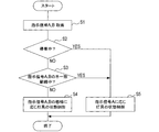
- FIG. 2 is a flowchart illustrating processing executed by the left lamp ECU and the right lamp ECU according to the first embodiment.
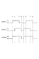
- FIG. 3 is an explanatory diagram illustrating an example of the state transition of the lamp set according to the mode of the instruction signal according to the first embodiment.
- FIG. 4 is an explanatory diagram illustrating an example of the state transition of the lamp set according to the mode of the instruction signal according to the second embodiment.
- FIG. 5 is a block diagram illustrating a configuration of a lamp control system according to the third embodiment.
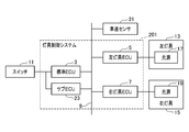
- FIG. 6 is a block diagram illustrating a configuration of a lamp control system according to the fourth embodiment.
- the lamp control system 1 is a system provided in a vehicle. Below, let the vehicle provided with the lamp control system 1 be an own vehicle.
- the lamp control system 1 includes a standard ECU 3, a left lamp ECU 5, a right lamp ECU 7, and a communication line 9.
- Standard ECU 3 is a standard function ECU, and executes various controls in the host vehicle.
- the standard ECU 3 obtains an input signal from the switch 11 provided in the host vehicle.
- the switch 11 is a switch for switching on / off of the left lamp 13 and the right lamp 15 included in the host vehicle, and is turned on or off according to a user operation.
- the standard ECU 3 acquires an on input signal from the switch 11. Further, when the switch 11 is turned off by a user operation, the standard ECU 3 acquires an off input signal from the switch 11.
- the standard ECU 3 In response to an input signal from the switch 11, the standard ECU 3 generates and outputs instruction signals A and B (a plurality of instruction signals) for instructing the states (lighting or extinguishing) of the left lamp 13 and the right lamp 15 included in the host vehicle. To do.
- the instruction signals A and B are output at a predetermined time difference. Specifically, for example, the instruction signal A is output first, and then the instruction signal B is output.
- the instruction signals A and B have the same value. For example, when the input signal from the switch 11 is on, the instruction signals A and B output from the standard ECU 3 are both on. When the input signal from the switch 11 is off, the instruction signals A and B output from the standard ECU 3 are both off.
- the left lamp ECU 5 is an additional function ECU for the left lamp 13 and acquires instruction signals A and B from the standard ECU 3 via the communication line 9.
- the left lamp ECU 5 controls the state of the left lamp 13 according to the acquired instruction signals A and B (a plurality of instruction signals). That is, the left lamp ECU 5 turns on or off the light source 17 included in the left lamp 13 in accordance with the instruction signals A and B. The specific process executed by the left lamp ECU 5 will be described later.
- the left lamp ECU 5 acquires vehicle speed information of the host vehicle from the vehicle speed sensor 21 via the communication line 9.
- the right lamp ECU 7 is an additional function ECU for the right lamp 15 and acquires instruction signals A and B from the standard ECU 3 through the communication line 9.
- the right lamp ECU 7 controls the state of the right lamp 15 according to the acquired instruction signals A and B (a plurality of instruction signals). That is, the right lamp ECU 7 turns on or off the light source 19 included in the right lamp 15 according to the instruction signals A and B. A specific process executed by the right lamp ECU 7 will be described later. Further, the right lamp ECU 7 acquires the vehicle speed information of the host vehicle from the vehicle speed sensor 21 via the communication line 9.
- the communication line 9 connects the standard ECU 3 to the left lamp ECU 5 and the right lamp ECU 7, and transmits the instruction signals A and B output from the standard ECU 3 to the left lamp ECU 5 and the right lamp ECU 7.
- the standard ECU 3 is an example of an instruction signal generation unit that generates an instruction signal for instructing the state of the lamp, and functions as an instruction signal generation unit.
- the left lamp ECU 5 and the right lamp ECU 7 are an example of a control unit that controls the state of the lamp in accordance with the instruction signal, and functions as a control unit.
- the left lamp ECU 5 acquires instruction signals A and B from the standard ECU 3 (S1).
- the left lamp ECU 5 determines whether or not the host vehicle is stopped based on the vehicle speed information acquired from the vehicle speed sensor 21 (that is, whether or not the vehicle speed of the host vehicle is 0) (S2).
- the process proceeds to the determination process in step S3.
- the left lamp ECU 5 determines that the vehicle is stopped (S2: YES)
- the process proceeds to step S5.
- the left lamp ECU 5 determines whether or not the state of the instruction signals A and B acquired from the standard ECU 3 is inconsistent at the present time, and whether or not the state has continued for a predetermined time (the predetermined time has elapsed in the inconsistent state). (S3).
- the state in which the values of the instruction signals A and B do not coincide is, for example, when the instruction signal A is on, the instruction signal B is off, or the instruction signal A is off. It is on.
- the left lamp ECU 5 proceeds to the process of step S4 when the values of the instruction signals A and B are not matched and the state has not continued for a predetermined time or longer (S3: NO).
- the inconsistent state continues (S3: YES)
- the left lamp ECU 5 proceeds to the process of step S5.
- the left lamp ECU 5 controls the state of the left lamp 13 in accordance with the modes of the instruction signals A and B (S4). At this time, the left lamp ECU 5 controls the state of the left lamp 13 so as to be set in advance according to the modes of the instruction signals A and B. Specifically, the left lamp ECU 5 determines that the light source 17 of the left lamp 13 when at least one of the instruction signals A and B (of the plurality of instruction signals) is on (a value that instructs lighting). Lights up. On the other hand, the left lamp ECU 5 turns off the light source 17 of the left lamp 13 when both of the instruction signals A and B are off (value that instructs turning off). Thus, the left lamp ECU 5 changes the state of the left lamp 13 to a state set in advance according to the modes of the instruction signals A and B.
- FIG. 3 shows an example of the state transition of the left lamp 13 set according to the modes of the instruction signals A and B.
- At times t 1 to t 4 and t 5 to t 8 at least one of the instruction signals A and B is on, so the left lamp 13 is in a lighting state.
- the time t 1 earlier, at time t 4 ⁇ t 5, time t 8 after an instruction signal A, for instructing signal both B is off the left lamp 13 is in the off state.
- the left lamp ECU 5 controls the state of the left lamp 13 according to the instruction signal A (S5). Specifically, the left lamp ECU 5 turns on the light source 17 of the left lamp 13 when the instruction signal A is on, and turns off the light source 17 of the left lamp 13 when the instruction signal A is off. At this time, the instruction signal B does not affect the state of the left lamp 13.
- the instruction signal A is an example of a reference instruction signal that controls the state of the left lamp 13 and the right lamp 15.
- the right lamp ECU 7 executes the same process as the left lamp ECU 5 (the process shown in FIG. 2) and controls the state of the right lamp 15.
- the lamp control system 1 controls the states of the left lamp 13 and the right lamp 15 according to the modes of the instruction signals A and B (a plurality of instruction signals). . Therefore, there is a high possibility that the state of the left lamp 13 and the right lamp 15 can be appropriately maintained as compared with the control method using one instruction signal.
- an erroneous instruction signal is output due to, for example, an abnormal operation of the ECU or a communication abnormality.
- the state of the left lamp 13 and the right lamp 15 is different from the state requested by the user operation. Specifically, for example, the left lamp 13 and the right lamp 15 are extinguished while the switch 11 is on, and the driver's field of view is lost, or the left lamp 13 and the right lamp are switched while the switch 11 is off. The lamp 15 is turned on, and battery consumption is accelerated.
- the lamp control system 1 according to the present embodiment can suppress the occurrence of the above situation.
- the lamp control system 1 lights the left lamp 13 and the right lamp 15 when at least one of the instruction signals A and B (among a plurality of instruction signals) is on. To do. Thereby, the lamp control system 1 according to the present embodiment, when the left lamp 13 and the right lamp 15 are to be turned on, even if an abnormality occurs in the value of one of the instruction signals A and B, The left lamp 13 and the right lamp 15 can be turned on.
- the lamp control system 1 according to the present embodiment controls the state of the left lamp 13 and the right lamp 15 according to the instruction signal A when the host vehicle is stopped. Thereby, the lamp control system 1 according to the present embodiment can reduce the processing burden on the left lamp ECU 5 and the right lamp ECU 7.
- the reason why the lamp control system 1 according to the present embodiment employs such a control process is as follows. When the host vehicle is stopped, even if the states of the left lamp 13 and the right lamp 15 do not match the state of the switch 11 (the state requested by the user operation), it does not cause a serious problem. is there.
- the left lamp ECU 5 basically executes the same processes as those in the first embodiment (the process shown in FIG. 2). Therefore, in the following description, description of common processing will be omitted, and differences will be mainly described.
- the left lamp ECU 5 controls the state of the left lamp 13 as follows in the process of step S4 (determination process as to whether or not the inconsistency state of the instruction signals A and B is continuing).
- the left lamp ECU 5 controls the state of the left lamp 13 in accordance with the instruction signal A when the left lamp 13 is in the extinguished state at the time of executing the process of step S4. Specifically, for example, the left lamp ECU 5 turns on the left lamp 13 when the instruction signal A is on, and keeps the left lamp 13 off when the instruction signal A is off. . At this time, the instruction signal B does not affect the state of the left lamp 13.
- the left lamp ECU 5 when the left lamp 13 is in a lighting state at the time of executing the process of step S4, the left lamp ECU 5 is turned on at least one of the instruction signals A and B (among a plurality of instruction signals). The lighting state is maintained on the condition that there is. On the other hand, when both the instruction signals A and B are off, the left lamp ECU 5 turns off the left lamp 13.
- FIG. 4 shows an example of the state transition of the left lamp 13 set according to the modes of the instruction signals A and B as described above.
- the left lamp 13 was turned off.
- the instruction signal A is turned on in response to an instruction signal A
- the left lamp 13 is illuminated.
- the instruction signal B does not affect the state of the left lamp 13.
- the left lamp 13 is in a lighting state. Thereafter, even when the instruction signal A is turned off at time t 3 , the lighting state of the left lamp 13 is maintained because at least one of the instruction signals A and B (instruction signal B) is on.
- the left lamp 13 is illuminated. Then, at time t 4, when the instruction signal A, the instruction signal of both B is turned off, the left lamp 13 is turned off. At the time immediately before time t 5, the left lamp 13 is turned off. Then, at time t 5, since the instruction signal A is turned off, the light-out state of the left lamp 13 is maintained. At this time, the instruction signal B does not affect the state of the left lamp 13 even if it is on.
- the left lamp 13 is turned off. Then, at time t 6, when the instruction signal A is turned on in response to an instruction signal A, the left lamp 13 is illuminated. At this time, the instruction signal B does not affect the state of the left lamp 13.
- the left lamp 13 is in a lighting state. Then, at time t 7, even when the instruction signal B is turned off, the instruction signal A, one of B, for at least one indication signal (indication signal A) is on, the lighting state of the left lamp 13 is maintained.
- the left lamp 13 is illuminated. Then, at time t 8, when the instruction signal A, the instruction signal of both B is turned off, the left lamp 13 is turned off.
- the right lamp ECU 7 performs the same processing as the left lamp ECU 5 and controls the state of the right lamp 15.
- the lamp control system 1 when the left lamp 13 and the right lamp 15 are in the lighting state at the time of executing the determination process whether or not the inconsistency state of the plurality of instruction signals is continuing, If at least one of the instruction signals A and B is on, the lighting state of the left lamp 13 and the right lamp 15 is maintained. Thereby, when the lighting control system 1 according to the present embodiment should maintain the lighting state of the left lamp 13 and the right lamp 15, even if an abnormality occurs in the value of one of the instruction signals A and B, The lighting state of the left lamp 13 and the right lamp 15 can be maintained.
- the lamp control system 1 when the left lamp 13 and the right lamp 15 are in a lighting state at the time when the determination process is executed, the lamp control system 1 according to the present embodiment responds to the instruction signal A and the left lamp 13 and the right lamp 15. Control the state of Thereby, the lamp control system 1 according to the present embodiment can reduce the processing burden on the left lamp ECU 5 and the right lamp ECU 7.
- the lamp control system 101 includes a communication line 9A and a communication line 9B.
- the communication line 9A connects the standard ECU 3 and the left lamp ECU 5.
- the communication line 9B connects the left lamp ECU 5 and the right lamp ECU 7. There is no communication line that directly connects the standard ECU 3 and the right lamp ECU 7.
- Instruction signals A and B output from the standard ECU 3 are transmitted to the left lamp ECU 5, and further transmitted from the left lamp ECU 5 to the right lamp ECU 7.
- the left lamp ECU 5 and the right lamp ECU 7 execute the same process as the first embodiment (the process shown in FIG. 2).
- the lamp control system 201 includes a sub ECU 23.
- the signal from the switch 11 is input to both the standard ECU 3 and the sub ECU 23.
- the value of the input signal to the standard ECU 3 and the value of the input signal to the sub ECU 23 are the same value when the operation of the switch 11 is normal.
- the standard ECU 3 generates and outputs an instruction signal A for instructing the state (lit or extinguished) of the left lamp 13 and the right lamp 15 in accordance with the input signal from the switch 11.
- the sub ECU 23 outputs an instruction signal B instructing the state of the left lamp 13 and the right lamp 15 according to the input signal from the switch 11.
- the value of the instruction signal A and the value of the instruction signal B are the same value when the operations of the switch 11, the standard ECU 3, and the sub ECU 23 are normal.
- the communication line 9 connects the standard ECU 3 with the left lamp ECU 5 and the right lamp ECU 7, and connects the sub ECU 23 with the left lamp ECU 5 and the right lamp ECU 7.
- the left lamp ECU 5 acquires the instruction signal A from the standard ECU 3 and the instruction signal B from the sub ECU 23 via the communication line 9.
- the right lamp ECU 7 acquires the instruction signal A from the standard ECU 3 and the instruction signal B from the sub ECU 23 via the communication line 9.
- the transmission path of the instruction signal A is a path from the standard ECU 3 to the left lamp ECU 5 and the right lamp ECU 7 via the communication line 9.
- the transmission path of the instruction signal B is a path from the sub ECU 23 to the left lamp ECU 5 and the right lamp ECU 7 via the communication line 9. Therefore, in the transmission path of the instruction signal from the standard ECU 3 to the left lamp ECU 5 and the right lamp ECU 7, the transmission path of the instruction signal A and the transmission path of the instruction signal B are different paths.
- the left lamp ECU 5 and the right lamp ECU 7 execute the same process as the first embodiment (the process shown in FIG. 2).
- the transmission path of the instruction signal A and the transmission path of the instruction signal B are different.
- the lamp control system 201 according to the present embodiment has a failure in one of the transmission paths, and even when an abnormality occurs in the value of the instruction signal passing through the transmission path, the other transmission path, An instruction signal having a normal value can be transmitted to the left lamp ECU 5 and the right lamp ECU 7.
- the number of instruction signals may be other than two.
- step S2 it is determined whether or not the host vehicle is stopped based on the vehicle speed information of the host vehicle, but this is not restrictive. Whether the host vehicle is stopped may be determined based on, for example, the setting state (on or off) of the ignition switch of the host vehicle. Specifically, the left lamp ECU 5 determines whether or not the ignition switch of the host vehicle is on. If the ignition switch is on, the process proceeds to the determination process in step S3. On the other hand, when the ignition switch is OFF, the left lamp ECU 5 proceeds to the process of step S5. In addition, although the process example by left lamp ECU5 was demonstrated here, the same process should just be performed also in right lamp ECU7. In the lamp control system 1, the same effect (1C) as in the first embodiment can be obtained even when it is determined whether or not the host vehicle is stopped based on such a setting state of the ignition switch. It is done.
- the left lamp ECU 5 determines whether or not the ignition switch of the host vehicle is on. If the ignition switch is on, the process proceeds to the determination process
- step S2 In the processing of the left lamp ECU 5 and the right lamp ECU 7 described in the first to fourth embodiments, the determination process of step S2 is omitted, and the determination of step S3 is always performed after the execution of the process of step S1. Processing may be executed. Further, in the processes of the left lamp ECU 5 and the right lamp ECU 7, the determination process of step S3 may be omitted, and if a negative determination is made in the determination process of step S2, the process of step S4 may always be executed. Further, in the processes of the left lamp ECU 5 and the right lamp ECU 7, the determination process of step S2 and step S3 may be omitted, and the determination process of step S4 may always be performed after the process of step S1.
- the correspondence between the modes of the instruction signals A and B and the states of the left lamp 13 and the right lamp 15 is not limited to the correspondence described in the first to fourth embodiments, and is set as appropriate. can do. Further, the state control of the left lamp 13 and the right lamp 15 may be controlled according to the combination of the modes of the instruction signals A and B and the states of the left lamp 13 and the right lamp 15.
- the state of the left lamp 13 and the right lamp 15 indicated by the instruction signals A and B may be a state other than lighting / extinguishing.
- the instruction signals A and B may be signals indicating the high beam / low beam, the illuminance in the light sources 17 and 19, the color of light, the light irradiation range, and the like.
- the functions of one component in the embodiment are distributed as a plurality of components, or the functions of a plurality of components are integrated into one component. Or you may.
- at least a part of the configurations in the embodiments may be replaced with a known configuration having a similar function.
- a part of the configuration in the embodiment may be omitted.
- at least a part of the configurations in the embodiments may be added to or replaced with the configurations in the other embodiments.
- the lamp control technology of the present disclosure is realized in various forms such as a program for causing a computer to function as the lamp control system, a medium on which the program is recorded, a lamp control method, and the like in addition to the lamp control system. You can also.
Landscapes
- Engineering & Computer Science (AREA)
- Mechanical Engineering (AREA)
- Lighting Device Outwards From Vehicle And Optical Signal (AREA)
Abstract
車両が備える灯具(13、15)の状態を指示する指示信号を生成する指示信号生成ユニット(3)と、指示信号に応じて、灯具の状態を制御する制御ユニット(5、7)と、を備え、指示信号生成ユニットは、複数の指示信号を生成し、制御ユニットは、複数の指示信号の態様に応じて、灯具の状態を制御する灯具制御システム(1、101、201)。
Description
本開示は灯具制御システムに関する。
車両が備える灯具の点灯/消灯は、以下のように制御される。ユーザが車内のスイッチを操作すると、ECUには、操作に応じた入力信号が入力される。ECUは、入力信号に応じてリレーをオン又はオフの状態にすることで、灯具の点灯/消灯を制御する。これに対して、特許文献1には、上記制御に使用するECUを、標準機能ECUと、灯具用の付加機能ECUとに分けることが提案されている。
特許文献1に記載の技術では、標準機能ECUが指示信号を出力し、灯具用の付加機能ECUが指示信号に応じて灯具の状態を制御する。このとき、何らかの理由で誤った指示信号が出力された場合には、灯具の状態が、ユーザ操作により要求された状態とは異なってしまう。
本開示は、灯具の状態を適切に制御できる灯具制御システムを提供することを目的とする。
本開示の灯具制御システムは、車両が備える灯具の状態を指示する指示信号を生成する指示信号生成ユニットと、指示信号に応じて、灯具の状態を制御する制御ユニットと、を備える。指示信号生成ユニットは、複数の指示信号を生成し、制御ユニットは、複数の指示信号の態様に応じて、灯具の状態を制御する。
そのため、本開示の灯具制御システムでは、1つの指示信号を用いる制御システムに比べて、灯具の状態を適切に制御することができる。
本開示の実施形態を図面に基づき説明する。
<第1の実施形態>
1.灯具制御システム1の構成
本実施形態に係る灯具制御システム1の構成を図1に基づき説明する。灯具制御システム1は、車両が備えるシステムである。以下では、灯具制御システム1を備える車両を自車両とする。灯具制御システム1は、標準ECU3、左灯具ECU5、右灯具ECU7、及び通信線9を備える。
<第1の実施形態>
1.灯具制御システム1の構成
本実施形態に係る灯具制御システム1の構成を図1に基づき説明する。灯具制御システム1は、車両が備えるシステムである。以下では、灯具制御システム1を備える車両を自車両とする。灯具制御システム1は、標準ECU3、左灯具ECU5、右灯具ECU7、及び通信線9を備える。
標準ECU3は、標準機能ECUであり、自車両における各種制御を実行する。標準ECU3は、自車両の車内に設けられたスイッチ11から入力信号を取得する。スイッチ11は、自車両が備える左灯具13及び右灯具15の点灯/消灯を切り替えるためのスイッチであり、ユーザの操作に応じて、オン又はオフの状態となる。スイッチ11がユーザの操作によりオンの状態となっているとき、標準ECU3は、スイッチ11からオンの入力信号を取得する。また、スイッチ11がユーザの操作によりオフの状態となっているとき、標準ECU3は、スイッチ11からオフの入力信号を取得する。
標準ECU3は、スイッチ11からの入力信号に応じて、自車両が備える左灯具13及び右灯具15の状態(点灯又は消灯)を指示する指示信号A、B(複数の指示信号)を生成し出力する。指示信号A、Bの出力は、所定の時間差で行われる。具体的には、例えば、最初に指示信号Aが出力され、その後、指示信号Bが出力される。標準ECU3の動作が正常の場合、指示信号A、Bは、同じ値となる。例えば、スイッチ11からの入力信号がオンの場合、標準ECU3から出力される指示信号A、Bは、いずれもオンである。また、スイッチ11からの入力信号がオフの場合、標準ECU3から出力される指示信号A、Bは、いずれもオフである。
左灯具ECU5は、左灯具13用の付加機能ECUであり、通信線9を介して、標準ECU3からの指示信号A、Bを取得する。左灯具ECU5は、取得した指示信号A、B(複数の指示信号)に応じて、左灯具13の状態を制御する。すなわち、左灯具ECU5は、指示信号A、Bに応じて、左灯具13が備える光源17を点灯又は消灯とする。なお、左灯具ECU5が実行する具体的な処理については後述する。また、左灯具ECU5は、通信線9を介して、車速センサ21から自車両の車速情報を取得する。
右灯具ECU7は、右灯具15用の付加機能ECUであり、通信線9を介して、標準ECU3からの指示信号A、Bを取得する。右灯具ECU7は、取得した指示信号A、B(複数の指示信号)に応じて、右灯具15の状態を制御する。すなわち、右灯具ECU7は、指示信号A、Bに応じて、右灯具15が備える光源19を点灯又は消灯とする。なお、右灯具ECU7が実行する具体的な処理については後述する。また、右灯具ECU7は、通信線9を介して、車速センサ21から自車両の車速情報を取得する。
通信線9は、標準ECU3と、左灯具ECU5及び右灯具ECU7とを接続し、標準ECU3から出力された指示信号A、Bを、左灯具ECU5及び右灯具ECU7に伝達する。なお、標準ECU3は、灯具の状態を指示する指示信号を生成する指示信号生成ユニットの一例であり、指示信号生成手段として機能する。また、左灯具ECU5及び右灯具ECU7は、指示信号に応じて、灯具の状態を制御する制御ユニットの一例であり、制御手段として機能する。
2.左灯具ECU5及び右灯具ECU7が実行する処理
左灯具ECU5が所定時間ごとに繰り返し実行する処理を図2、図3に基づき説明する。
左灯具ECU5が所定時間ごとに繰り返し実行する処理を図2、図3に基づき説明する。
図2に示すように、本実施形態に係る左灯具ECU5は、標準ECU3から指示信号A、Bを取得する(S1)。次に、左灯具ECU5は、車速センサ21から取得した車速情報に基づいて、自車両が停車中か否か(すなわち、自車両の車速が0であるか否か)を判断する(S2)。その結果、左灯具ECU5は、停車中ではないと判断した場合(S2:NO)、ステップS3の判定処理に進む。一方、左灯具ECU5は、停車中と判断した場合(S2:YES)、ステップS5の処理に進む。
左灯具ECU5は、現時点において、標準ECU3から取得した指示信号A、Bの値が不一致の状態になってから、その状態が所定時間以上継続しているか否か(不一致の状態で所定時間が経過したか否か)を判断する(S3)。なお、指示信号A、Bの値が不一致の状態とは、例えば、指示信号Aがオンのときに、指示信号Bがオフの状態、又は、指示信号Aがオフのときに、指示信号Bがオンの状態である。その結果、左灯具ECU5は、指示信号A、Bの値が不一致の状態になってから、その状態が所定時間以上継続していない場合(S3:NO)、ステップS4の処理に進む。一方、左灯具ECU5は、不一致の状態が継続している場合(S3:YES)、ステップS5の処理に進む。
左灯具ECU5は、指示信号A、Bの態様に応じて、左灯具13の状態を制御する(S4)。このとき、左灯具ECU5は、指示信号A、Bの態様に応じて、左灯具13の状態を、予め設定しておいた状態となるように制御する。具体的には、左灯具ECU5は、指示信号A、Bのうち(複数の指示信号のうち)、少なくとも1つの指示信号がオン(点灯を指示する値)である場合、左灯具13の光源17を点灯する。一方、左灯具ECU5は、指示信号A、Bの両方の指示信号がオフ(消灯を指示する値)である場合、左灯具13の光源17を消灯する。このように、左灯具ECU5は、左灯具13の状態を、指示信号A、Bの態様に応じて予め設定された状態にする。
指示信号A、Bの態様に応じて設定された左灯具13の状態遷移の例を図3に示す。時刻t1~t4、t5~t8においては、指示信号A、Bのうち、少なくとも1つの指示信号がオンであるため、左灯具13は点灯状態となっている。一方、時刻t1以前、時刻t4~t5、時刻t8以降においては、指示信号A、Bの両方の指示信号がオフであるため、左灯具13は消灯状態となっている。
また、左灯具ECU5は、上記ステップS2又はステップS3の判定処理で肯定判断された場合(S2又はS3:YES)、指示信号Aに応じて、左灯具13の状態を制御する(S5)。具体的には、左灯具ECU5は、指示信号Aがオンである場合、左灯具13の光源17を点灯し、指示信号Aがオフである場合、左灯具13の光源17を消灯する。このとき、指示信号Bは、左灯具13の状態に影響しない。なお、指示信号Aは、左灯具13及び右灯具15の状態を制御する基準指示信号の一例である。また、右灯具ECU7は、左灯具ECU5と同様の処理(図2に示した処理)を実行し、右灯具15の状態を制御する。
3.灯具制御システム1が奏する効果
(1A)本実施形態に係る灯具制御システム1は、指示信号A、B(複数の指示信号)の態様に応じて、左灯具13及び右灯具15の状態を制御する。そのため、1つの指示信号を用いる制御方法に比べて、左灯具13及び右灯具15の状態を適切に維持できる可能性が高い。
(1A)本実施形態に係る灯具制御システム1は、指示信号A、B(複数の指示信号)の態様に応じて、左灯具13及び右灯具15の状態を制御する。そのため、1つの指示信号を用いる制御方法に比べて、左灯具13及び右灯具15の状態を適切に維持できる可能性が高い。
すなわち、1つの指示信号を用いる制御方法の場合には、例えば、ECUの動作異常や通信異常等に起因して、誤った指示信号が出力されてしまう。その結果、左灯具13及び右灯具15の状態は、ユーザ操作により要求された状態とは異なってしまう。具体的には、例えばスイッチ11がオンの状態であるのに左灯具13及び右灯具15が消灯し、ドライバの視界が喪失したり、スイッチ11がオフの状態であるのに左灯具13及び右灯具15が点灯し、バッテリの消耗が早まったりする。これに対して、本実施形態に係る灯具制御システム1は、上記のような事態の発生を抑制できる。
(1B)本実施形態に係る灯具制御システム1は、指示信号A、Bのうち(複数の指示信号のうち)、少なくとも1つの指示信号がオンである場合、左灯具13及び右灯具15を点灯する。これにより、本実施形態に係る灯具制御システム1は、左灯具13及び右灯具15を点灯状態にすべき場合、指示信号A、Bのうち、一方の指示信号の値に異常が生じても、左灯具13及び右灯具15を点灯状態にすることができる。
(1C)本実施形態に係る灯具制御システム1は、自車両が停車中である場合、指示信号Aに応じて、左灯具13及び右灯具15の状態を制御する。これにより、本実施形態に係る灯具制御システム1は、左灯具ECU5及び右灯具ECU7の処理負担を軽減できる。なお、本実施形態に係る灯具制御システム1が、このような制御処理を採用した理由は、次のとおりである。自車両が停車中の場合には、仮に、左灯具13及び右灯具15の状態が、スイッチ11の状態(ユーザ操作により要求された状態)と一致しなくても、深刻な問題とならないからである。
(1D)本実施形態に係る灯具制御システム1は、指示信号A、Bの値が不一致の状態になってから、その状態が所定時間以上継続している場合、指示信号Aに応じて、左灯具13及び右灯具15の状態を制御する。これにより、本実施形態に係る灯具制御システム1は、左灯具13及び右灯具15の点灯状態が過度に継続することを抑制できる。
<第2の実施形態>
1.灯具制御システム1の構成
本実施形態に係る灯具制御システム1の構成は、上記第1の実施形態(図1に示した構成)と同様である。
1.灯具制御システム1の構成
本実施形態に係る灯具制御システム1の構成は、上記第1の実施形態(図1に示した構成)と同様である。
2.左灯具ECU5及び右灯具ECU7が実行する処理
本実施形態に係る左灯具ECU5は、基本的に上記第1の実施形態(図2に示した処理)と同様の処理を実行する。よって、以降の説明では、共通する処理について説明を省略し、相違点を中心に説明する。
本実施形態に係る左灯具ECU5は、基本的に上記第1の実施形態(図2に示した処理)と同様の処理を実行する。よって、以降の説明では、共通する処理について説明を省略し、相違点を中心に説明する。
本実施形態に係る左灯具ECU5は、ステップS4の処理(指示信号A、Bの不一致状態が継続中か否かの判定処理)において、以下のように、左灯具13の状態を制御する。左灯具ECU5は、ステップS4の処理を実行する時点において、左灯具13が消灯状態の場合、指示信号Aに応じて、左灯具13の状態を制御する。具体的には、左灯具ECU5は、例えば、指示信号Aがオンである場合、左灯具13を点灯状態とし、一方、指示信号Aがオフである場合、左灯具13を消灯状態のままとする。このとき、指示信号Bは、左灯具13の状態に影響しない。
また、左灯具ECU5は、ステップS4の処理を実行する時点において、左灯具13が点灯状態の場合、指示信号A、Bのうち(複数の指示信号のうち)、少なくとも1つの指示信号がオンであることを条件として、点灯状態を維持する。一方、左灯具ECU5は、指示信号A、Bの両方の指示信号がオフである場合、左灯具13を消灯状態とする。
上記のように、指示信号A、Bの態様に応じて設定された左灯具13の状態遷移の例を図4に示す。時刻t1の直前の時点においては、左灯具13は消灯状態であった。その後、時刻t1において、指示信号Aがオンになった場合には、指示信号Aに応じて、左灯具13は点灯状態となる。このとき、指示信号Bは、左灯具13の状態に影響しない。
時刻t3の直前の時点においては、左灯具13は点灯状態である。その後、時刻t3において、指示信号Aがオフになっても、指示信号A、Bのうち、少なくとも1つの指示信号(指示信号B)がオンであるため、左灯具13の点灯状態は維持される。
時刻t4の直前の時点においては、左灯具13は点灯状態である。その後、時刻t4において、指示信号A、Bの両方の指示信号がオフになった場合には、左灯具13は消灯状態となる。時刻t5の直前の時点においては、左灯具13は消灯状態である。その後、時刻t5において、指示信号Aがオフであるため、左灯具13の消灯状態は維持される。このとき、指示信号Bは、オンであっても左灯具13の状態に影響しない。
時刻t6の直前の時点においては、左灯具13は消灯状態である。その後、時刻t6において、指示信号Aがオンになった場合には、指示信号Aに応じて、左灯具13は点灯状態となる。このとき、指示信号Bは、左灯具13の状態に影響しない。
時刻t7の直前の時点においては、左灯具13は点灯状態である。その後、時刻t7において、指示信号Bがオフになっても、指示信号A、Bのうち、少なくとも1つの指示信号(指示信号A)がオンであるため、左灯具13の点灯状態は維持される。
時刻t8の直前の時点においては、左灯具13は点灯状態である。その後、時刻t8において、指示信号A、Bの両方の指示信号がオフになった場合には、左灯具13は消灯状態となる。なお、右灯具ECU7は、左灯具ECU5と同様の処理を実行し、右灯具15の状態を制御する。
3.灯具制御システム1が奏する効果
以上詳述した本実施形態に係る灯具制御システム1は、上記第1の実施形態の効果(1A)、(1C)、(1D)に加え、以下の効果が得られる。
以上詳述した本実施形態に係る灯具制御システム1は、上記第1の実施形態の効果(1A)、(1C)、(1D)に加え、以下の効果が得られる。
(2A)本実施形態に係る灯具制御システム1は、複数の指示信号の不一致状態が継続中か否かの判定処理を実行する時点において、左灯具13及び右灯具15が点灯状態である場合、指示信号A、Bのうち、少なくとも1つの指示信号がオンであれば、左灯具13及び右灯具15の点灯状態を維持する。これにより、本実施形態に係る灯具制御システム1は、左灯具13及び右灯具15の点灯状態を維持すべき場合、指示信号A、Bのうち、一方の指示信号の値に異常が生じても、左灯具13及び右灯具15の点灯状態を維持することができる。
また、本実施形態に係る灯具制御システム1は、この判定処理を実行する時点において、左灯具13及び右灯具15が点灯状態である場合、指示信号Aに応じて、左灯具13及び右灯具15の状態を制御する。これにより、本実施形態に係る灯具制御システム1は、左灯具ECU5及び右灯具ECU7の処理負担を軽減できる。
<第3の実施形態>
1.灯具制御システム101の構成
図5に示すように、本実施形態に係る灯具制御システム101の構成は、基本的に上記第1の実施形態と同様である。よって、以降の説明では、共通する構成について説明を省略し、相違点を中心に説明する。本実施形態に係る灯具制御システム101は、通信線9Aと通信線9Bとを備える。通信線9Aは、標準ECU3と左灯具ECU5とを接続する。一方、通信線9Bは、左灯具ECU5と右灯具ECU7とを接続する。なお、標準ECU3と右灯具ECU7とを直接接続する通信線は存在しない。
1.灯具制御システム101の構成
図5に示すように、本実施形態に係る灯具制御システム101の構成は、基本的に上記第1の実施形態と同様である。よって、以降の説明では、共通する構成について説明を省略し、相違点を中心に説明する。本実施形態に係る灯具制御システム101は、通信線9Aと通信線9Bとを備える。通信線9Aは、標準ECU3と左灯具ECU5とを接続する。一方、通信線9Bは、左灯具ECU5と右灯具ECU7とを接続する。なお、標準ECU3と右灯具ECU7とを直接接続する通信線は存在しない。
標準ECU3から出力された指示信号A、Bは、左灯具ECU5に伝達され、さらに、左灯具ECU5から右灯具ECU7に伝達される。
2.左灯具ECU5及び右灯具ECU7が実行する処理
本実施形態に係る左灯具ECU5及び右灯具ECU7は、上記第1の実施形態(図2に示した処理)と同様の処理を実行する。
本実施形態に係る左灯具ECU5及び右灯具ECU7は、上記第1の実施形態(図2に示した処理)と同様の処理を実行する。
3.灯具制御システム101が奏する効果
本実施形態に係る灯具制御システム101は、上記第1の実施形態と同様の効果(1A)~(1D)を奏する。
本実施形態に係る灯具制御システム101は、上記第1の実施形態と同様の効果(1A)~(1D)を奏する。
<第4の実施形態>
1.灯具制御システム201の構成
図6に示すように、本実施形態に係る灯具制御システム201の構成は、基本的に上記第1の実施形態と同様である。よって、以降の説明では、共通する構成について説明を省略し、相違点を中心に説明する。本実施形態に係る灯具制御システム201は、サブECU23を備える。
1.灯具制御システム201の構成
図6に示すように、本実施形態に係る灯具制御システム201の構成は、基本的に上記第1の実施形態と同様である。よって、以降の説明では、共通する構成について説明を省略し、相違点を中心に説明する。本実施形態に係る灯具制御システム201は、サブECU23を備える。
スイッチ11からの信号は、標準ECU3とサブECU23との両方に入力される。標準ECU3への入力信号の値と、サブECU23への入力信号の値とは、スイッチ11の動作が正常の場合、同じ値となる。
標準ECU3は、スイッチ11からの入力信号に応じて、左灯具13及び右灯具15の状態(点灯又は消灯)を指示する指示信号Aを生成し出力する。一方、サブECU23は、スイッチ11からの入力信号に応じて、左灯具13及び右灯具15の状態を指示する指示信号B出力する。指示信号Aの値と、指示信号Bの値とは、スイッチ11、標準ECU3、及びサブECU23のそれぞれの動作が正常の場合、同じ値となる。
通信線9は、標準ECU3と、左灯具ECU5及び右灯具ECU7とを接続し、サブECU23と、左灯具ECU5及び右灯具ECU7とを接続している。左灯具ECU5は、通信線9を介して、標準ECU3からの指示信号Aを取得し、サブECU23からの指示信号Bを取得する。また、右灯具ECU7は、通信線9を介して、標準ECU3からの指示信号Aを取得し、サブECU23からの指示信号Bを取得する。
指示信号Aの伝達経路は、通信線9を介して、標準ECU3から左灯具ECU5及び右灯具ECU7に至る経路である。一方、指示信号Bの伝達経路は、通信線9を介して、サブECU23から左灯具ECU5及び右灯具ECU7に至る経路である。よって、標準ECU3から左灯具ECU5及び右灯具ECU7に至るまでの指示信号の伝達経路において、指示信号Aの伝達経路と指示信号Bの伝達経路とは、異なる経路である。
2.左灯具ECU5及び右灯具ECU7が実行する処理
本実施形態に係る左灯具ECU5及び右灯具ECU7は、上記第1の実施形態(図2に示した処理)と同様の処理を実行する。
本実施形態に係る左灯具ECU5及び右灯具ECU7は、上記第1の実施形態(図2に示した処理)と同様の処理を実行する。
3.灯具制御システム201が奏する効果
以上詳述した本実施形態に係る灯具制御システム1は、上記第1の実施形態の効果(1A)~(1D)に加え、以下の効果が得られる。
以上詳述した本実施形態に係る灯具制御システム1は、上記第1の実施形態の効果(1A)~(1D)に加え、以下の効果が得られる。
(4A)本実施形態に係る灯具制御システム201では、指示信号Aの伝達経路と指示信号Bの伝達経路とは異なる。これにより、本実施形態に係る灯具制御システム201は、どちらか一方の伝達経路に障害があり、その伝達経路を通る指示信号の値に異常が生じた場合でも、他方の伝達経路を介して、正常な値の指示信号を左灯具ECU5及び右灯具ECU7に伝達することができる。
<その他の実施形態>
以上、本開示の実施形態について説明したが、本開示は上記実施形態に限定されることなく、種々の形態を採り得る。
以上、本開示の実施形態について説明したが、本開示は上記実施形態に限定されることなく、種々の形態を採り得る。
(1)指示信号の数は、2以外であってもよい。
(2)上記第1~第4の実施形態において説明を行ったステップS2の判定処理では、自車両の車速情報に基づいて、自車両が停車中か否かを判断したが、この限りでない。自車両が停車中か否かの判断は、例えば、自車両のイグニッションスイッチの設定状態(オン又はオフ)を基準に判断してもよい。具体的には、左灯具ECU5は、自車両のイグニッションスイッチがオンであるか否かを判断し、イグニッションスイッチがオンの場合、ステップS3の判定処理に進む。一方、左灯具ECU5は、イグニッションスイッチがオフの場合、ステップS5の処理に進む。なお、ここでは、左灯具ECU5による処理例について説明を行ったが、右灯具ECU7においても同様の処理を実行すればよい。灯具制御システム1では、このようなイグニッションスイッチの設定状態に基づいて、自車両が停車中か否かを判断する場合であっても、上記第1の実施形態と同様の効果(1C)が得られる。
(3)上記第1~第4の実施形態において説明を行った左灯具ECU5及び右灯具ECU7の処理では、ステップS2の判定処理を省略し、ステップS1の処理の実行後に、常にステップS3の判定処理を実行するようにしてもよい。また、左灯具ECU5及び右灯具ECU7の処理では、ステップS3の判定処理を省略し、ステップS2の判定処理で否定判断された場合、常にステップS4の処理を実行するようにしてもよい。また、左灯具ECU5及び右灯具ECU7の処理では、ステップS2及びステップS3の判定処理を省略し、ステップS1の処理の実行後に、常にステップS4の判定処理を実行するようにしてもよい。
(4)指示信号A、Bの態様と、左灯具13及び右灯具15の状態との対応関係は、上記第1~第4の実施形態において説明を行った対応関係に限定されず、適宜設定することができる。また、左灯具13及び右灯具15の状態制御は、指示信号A、Bの態様と、左灯具13及び右灯具15の状態との組み合わせに応じて、制御するようにしてもよい。
(5)指示信号A、Bにより指示される左灯具13及び右灯具15の状態は、点灯/消灯以外の状態であってもよい。例えば、指示信号A、Bは、ハイビーム/ロービーム、光源17、19における照度、光の色、光の照射範囲等を指示する信号であってもよい。
(6)上記第1~第4の実施形態においては、実施形態における1つの構成要素が有する機能を複数の構成要素として分散させたり、複数の構成要素が有する機能を1つの構成要素に統合させたりしてもよい。また、上記第1~第4の実施形態においては、実施形態における構成のうち、少なくとも一部を、同様の機能を有する公知の構成に置き換えてもよい。また、上記第1~第4の実施形態においては、実施形態における構成の一部を省略してもよい。また、上記第1~第4の実施形態においては、実施形態における構成のうち、少なくとも一部を、他の実施形態の構成に対して付加又は置換してもよい。なお、本開示の実施形態は、請求の範囲に記載した文言によって特定される技術思想に基づくあらゆる態様が含まれる。
(7)本開示の灯具制御技術は、上記灯具制御システムの他、当該灯具制御システムとしてコンピュータを機能させるためのプログラム、このプログラムを記録した媒体、灯具制御方法等、種々の形態で実現することもできる。
1、101、201…灯具制御システム、3…標準ECU、5…左灯具ECU、7…右灯具ECU、9、9A、9B…通信線、11…スイッチ、13…左灯具、15…右灯具、17、19…光源、21…車速センサ、23…サブECU
Claims (6)
- 車両が備える灯具(13、15)の状態を指示する指示信号を生成する指示信号生成ユニット(3)と、
前記指示信号に応じて、前記灯具の状態を制御する制御ユニット(5、7)と、
を備え、
前記指示信号生成ユニットは、複数の指示信号を生成し、
前記制御ユニットは、前記複数の指示信号の態様に応じて、前記灯具の状態を制御する、灯具制御システム(1、101、201)。 - 前記制御ユニットは、前記複数の指示信号のうち、少なくとも1つの指示信号が点灯を指示するものである場合、前記灯具の状態を点灯状態にする、請求項1に記載の灯具制御システム。
- 前記制御ユニットは、
前記灯具が消灯状態である場合、前記複数の指示信号に含まれる基準指示信号に応じて、前記灯具の状態を制御し、
前記灯具が点灯状態である場合、前記複数の指示信号のうち、少なくとも1つの指示信号が点灯を指示するものであることを条件として、前記点灯状態を維持する、請求項1に記載の灯具制御システム。 - 前記制御ユニットは、前記車両が停車中の場合、又は、イグニッションスイッチがオフである場合、前記複数の指示信号に含まれる基準指示信号に応じて、前記灯具の状態を制御する、請求項1乃至3のいずれか一項に記載の灯具制御システム。
- 前記制御ユニットは、前記複数の指示信号の値が不一致の状態になってから、前記不一致の状態が所定時間以上継続する場合、前記複数の指示信号に含まれる基準指示信号に応じて、前記灯具の状態を制御する、請求項1乃至4のいずれか一項に記載の灯具制御システム。
- 前記複数の指示信号のうち、少なくとも1つの指示信号は、前記指示信号生成ユニットから前記制御ユニットまでの指示信号の伝達経路において、他の指示信号と異なる経路で伝達される、請求項1乃至5のいずれか一項に記載の灯具制御システム。
Priority Applications (1)
| Application Number | Priority Date | Filing Date | Title |
|---|---|---|---|
| US15/539,087 US10391924B2 (en) | 2014-12-24 | 2015-11-18 | Lighting device control system |
Applications Claiming Priority (2)
| Application Number | Priority Date | Filing Date | Title |
|---|---|---|---|
| JP2014260585A JP6458488B2 (ja) | 2014-12-24 | 2014-12-24 | 灯具制御システム |
| JP2014-260585 | 2014-12-24 |
Publications (1)
| Publication Number | Publication Date |
|---|---|
| WO2016103995A1 true WO2016103995A1 (ja) | 2016-06-30 |
Family
ID=56150028
Family Applications (1)
| Application Number | Title | Priority Date | Filing Date |
|---|---|---|---|
| PCT/JP2015/082401 Ceased WO2016103995A1 (ja) | 2014-12-24 | 2015-11-18 | 灯具制御システム |
Country Status (3)
| Country | Link |
|---|---|
| US (1) | US10391924B2 (ja) |
| JP (1) | JP6458488B2 (ja) |
| WO (1) | WO2016103995A1 (ja) |
Citations (3)
| Publication number | Priority date | Publication date | Assignee | Title |
|---|---|---|---|---|
| JPS5832770A (ja) * | 1981-08-20 | 1983-02-25 | 松下電工株式会社 | マツサ−ジ機 |
| JP2008113232A (ja) * | 2006-10-30 | 2008-05-15 | Hitachi Ltd | 要求映像が配信再生可能なテレビジョン装置 |
| JP2013048014A (ja) * | 2009-12-25 | 2013-03-07 | Sanyo Electric Co Ltd | 照明装置およびそれを利用した照明システム、制御装置、基地局装置、及び端末装置 |
Family Cites Families (20)
| Publication number | Priority date | Publication date | Assignee | Title |
|---|---|---|---|---|
| JP4313713B2 (ja) * | 2004-03-31 | 2009-08-12 | 本田技研工業株式会社 | 降雨判定装置及び方法 |
| JP4278106B2 (ja) * | 2005-06-17 | 2009-06-10 | 株式会社デンソー | 車両用前照灯装置 |
| JP4473232B2 (ja) * | 2006-04-26 | 2010-06-02 | 株式会社日本自動車部品総合研究所 | 車載用車両前方環境検出装置および車両用照明装置 |
| JP4458141B2 (ja) * | 2007-09-27 | 2010-04-28 | 株式会社デンソー | ライト制御装置 |
| JP4715878B2 (ja) * | 2008-07-18 | 2011-07-06 | 株式会社デンソー | ライト制御装置、およびライト制御プログラム |
| US8384289B2 (en) * | 2009-02-20 | 2013-02-26 | Keith Thomas | Method and system for a light sensing headlight modulator |
| US8754764B2 (en) * | 2009-08-24 | 2014-06-17 | Robert Bosch Gmbh | Good checking for vehicle pressure sensor |
| JP5787649B2 (ja) * | 2010-10-26 | 2015-09-30 | 株式会社小糸製作所 | 車両用灯具の制御装置および車両用灯具システム |
| JP5500265B2 (ja) * | 2010-11-12 | 2014-05-21 | トヨタ自動車株式会社 | 車両用配光制御システム及び車両用配光制御方法 |
| JP6091757B2 (ja) * | 2011-05-31 | 2017-03-08 | 株式会社小糸製作所 | 車両のランプ制御装置 |
| US9415718B2 (en) * | 2011-06-08 | 2016-08-16 | Denso Corporation | Vehicular headlight apparatus |
| DE102012210157A1 (de) * | 2012-06-15 | 2013-12-19 | Robert Bosch Gmbh | Verfahren und Vorrichtung zum Betreiben eines Scheinwerfers für ein Kraftfahrzeug |
| JP2014004922A (ja) * | 2012-06-25 | 2014-01-16 | Denso Corp | 車両用ヘッドランプ配光制御装置 |
| JP5947682B2 (ja) * | 2012-09-07 | 2016-07-06 | 株式会社デンソー | 車両用前照灯装置 |
| CN103112392B (zh) * | 2013-02-01 | 2014-08-27 | 深圳市保千里电子有限公司 | 汽车照明系统视角与转弯角度同步变化的控制方法及系统 |
| JP6089957B2 (ja) * | 2013-05-20 | 2017-03-08 | 株式会社デンソー | 灯火制御装置 |
| JP5630533B2 (ja) | 2013-05-29 | 2014-11-26 | 株式会社デンソー | 車両用制御システム |
| JP2015009570A (ja) * | 2013-06-26 | 2015-01-19 | 富士重工業株式会社 | 前照灯制御装置 |
| JP2015033944A (ja) * | 2013-08-09 | 2015-02-19 | スタンレー電気株式会社 | 車両用前照灯の点灯制御装置、車両用前照灯システム |
| JP6319204B2 (ja) * | 2015-06-26 | 2018-05-09 | 株式会社デンソー | 車両用の前照灯制御装置 |
-
2014
- 2014-12-24 JP JP2014260585A patent/JP6458488B2/ja not_active Expired - Fee Related
-
2015
- 2015-11-18 US US15/539,087 patent/US10391924B2/en active Active
- 2015-11-18 WO PCT/JP2015/082401 patent/WO2016103995A1/ja not_active Ceased
Patent Citations (3)
| Publication number | Priority date | Publication date | Assignee | Title |
|---|---|---|---|---|
| JPS5832770A (ja) * | 1981-08-20 | 1983-02-25 | 松下電工株式会社 | マツサ−ジ機 |
| JP2008113232A (ja) * | 2006-10-30 | 2008-05-15 | Hitachi Ltd | 要求映像が配信再生可能なテレビジョン装置 |
| JP2013048014A (ja) * | 2009-12-25 | 2013-03-07 | Sanyo Electric Co Ltd | 照明装置およびそれを利用した照明システム、制御装置、基地局装置、及び端末装置 |
Also Published As
| Publication number | Publication date |
|---|---|
| JP2016120762A (ja) | 2016-07-07 |
| US20180111544A1 (en) | 2018-04-26 |
| JP6458488B2 (ja) | 2019-01-30 |
| US10391924B2 (en) | 2019-08-27 |
Similar Documents
| Publication | Publication Date | Title |
|---|---|---|
| US9420671B1 (en) | Lighting control system | |
| BR112015004911A2 (pt) | sistema para controle de veículo motorizado, dispositivo de controle para um sistema de controle de veículo, veículo, e, método para controlar um sistema de veículo motorizado | |
| WO2012176549A1 (ja) | 電源制御システム、電源制御装置及び電源制御方法 | |
| JP6751905B2 (ja) | 照明制御装置、照明装置、および移動体 | |
| WO2014175089A1 (ja) | フェイルセーフ回路 | |
| WO2018185900A1 (ja) | 点灯制御装置、点灯制御方法及び点灯制御プログラム | |
| TW200717439A (en) | A multiple input circuit | |
| CN105828504B (zh) | 根据开关动作对灯进行控制的方法及装置 | |
| JP2016083260A5 (ja) | ||
| JP6307949B2 (ja) | 車両用制御システム | |
| JP6428553B2 (ja) | 車両の制御装置 | |
| WO2016103995A1 (ja) | 灯具制御システム | |
| CN102514616B (zh) | 工程车辆及其电控转向系统的安全控制方法与装置 | |
| JP2018039067A (ja) | 制御装置、制御システム、制御方法、及び制御プログラム | |
| JP2012066645A (ja) | 警告灯診断装置 | |
| CN108791043A (zh) | 一种汽车转向灯控制方法 | |
| JP2022191800A (ja) | 車両用シフトポジション決定装置 | |
| RU2579375C1 (ru) | Система светосигнальных огней автомобиля | |
| MY206002A (en) | Automobile headlight assembly | |
| JP2011157053A (ja) | 制動灯制御装置および車両用機器の制御装置 | |
| JP2018150887A (ja) | 電子制御装置 | |
| JP6349767B2 (ja) | 情報処理装置 | |
| JP6925742B2 (ja) | Led照明装置 | |
| JP2017030505A (ja) | 車両用ランプ制御装置 | |
| JP2015174625A (ja) | 車両用制御装置 |
Legal Events
| Date | Code | Title | Description |
|---|---|---|---|
| 121 | Ep: the epo has been informed by wipo that ep was designated in this application |
Ref document number: 15872564 Country of ref document: EP Kind code of ref document: A1 |
|
| WWE | Wipo information: entry into national phase |
Ref document number: 15539087 Country of ref document: US |
|
| NENP | Non-entry into the national phase |
Ref country code: DE |
|
| 122 | Ep: pct application non-entry in european phase |
Ref document number: 15872564 Country of ref document: EP Kind code of ref document: A1 |