WO2016103359A1 - 半導体装置 - Google Patents
半導体装置 Download PDFInfo
- Publication number
- WO2016103359A1 WO2016103359A1 PCT/JP2014/084108 JP2014084108W WO2016103359A1 WO 2016103359 A1 WO2016103359 A1 WO 2016103359A1 JP 2014084108 W JP2014084108 W JP 2014084108W WO 2016103359 A1 WO2016103359 A1 WO 2016103359A1
- Authority
- WO
- WIPO (PCT)
- Prior art keywords
- wiring
- wiring layer
- interposer
- signal
- reference potential
- Prior art date
Links
Images


Classifications
-
- H—ELECTRICITY
- H01—ELECTRIC ELEMENTS
- H01L—SEMICONDUCTOR DEVICES NOT COVERED BY CLASS H10
- H01L23/00—Details of semiconductor or other solid state devices
- H01L23/12—Mountings, e.g. non-detachable insulating substrates
- H01L23/14—Mountings, e.g. non-detachable insulating substrates characterised by the material or its electrical properties
- H01L23/147—Semiconductor insulating substrates
-
- H—ELECTRICITY
- H01—ELECTRIC ELEMENTS
- H01L—SEMICONDUCTOR DEVICES NOT COVERED BY CLASS H10
- H01L23/00—Details of semiconductor or other solid state devices
-
- H—ELECTRICITY
- H01—ELECTRIC ELEMENTS
- H01L—SEMICONDUCTOR DEVICES NOT COVERED BY CLASS H10
- H01L23/00—Details of semiconductor or other solid state devices
- H01L23/32—Holders for supporting the complete device in operation, i.e. detachable fixtures
-
- H—ELECTRICITY
- H01—ELECTRIC ELEMENTS
- H01L—SEMICONDUCTOR DEVICES NOT COVERED BY CLASS H10
- H01L23/00—Details of semiconductor or other solid state devices
- H01L23/48—Arrangements for conducting electric current to or from the solid state body in operation, e.g. leads, terminal arrangements ; Selection of materials therefor
- H01L23/488—Arrangements for conducting electric current to or from the solid state body in operation, e.g. leads, terminal arrangements ; Selection of materials therefor consisting of soldered or bonded constructions
- H01L23/498—Leads, i.e. metallisations or lead-frames on insulating substrates, e.g. chip carriers
- H01L23/49811—Additional leads joined to the metallisation on the insulating substrate, e.g. pins, bumps, wires, flat leads
-
- H—ELECTRICITY
- H01—ELECTRIC ELEMENTS
- H01L—SEMICONDUCTOR DEVICES NOT COVERED BY CLASS H10
- H01L23/00—Details of semiconductor or other solid state devices
- H01L23/48—Arrangements for conducting electric current to or from the solid state body in operation, e.g. leads, terminal arrangements ; Selection of materials therefor
- H01L23/488—Arrangements for conducting electric current to or from the solid state body in operation, e.g. leads, terminal arrangements ; Selection of materials therefor consisting of soldered or bonded constructions
- H01L23/498—Leads, i.e. metallisations or lead-frames on insulating substrates, e.g. chip carriers
- H01L23/49866—Leads, i.e. metallisations or lead-frames on insulating substrates, e.g. chip carriers characterised by the materials
- H01L23/49894—Materials of the insulating layers or coatings
-
- H—ELECTRICITY
- H01—ELECTRIC ELEMENTS
- H01L—SEMICONDUCTOR DEVICES NOT COVERED BY CLASS H10
- H01L23/00—Details of semiconductor or other solid state devices
- H01L23/52—Arrangements for conducting electric current within the device in operation from one component to another, i.e. interconnections, e.g. wires, lead frames
- H01L23/538—Arrangements for conducting electric current within the device in operation from one component to another, i.e. interconnections, e.g. wires, lead frames the interconnection structure between a plurality of semiconductor chips being formed on, or in, insulating substrates
- H01L23/5384—Conductive vias through the substrate with or without pins, e.g. buried coaxial conductors
-
- H—ELECTRICITY
- H01—ELECTRIC ELEMENTS
- H01L—SEMICONDUCTOR DEVICES NOT COVERED BY CLASS H10
- H01L23/00—Details of semiconductor or other solid state devices
- H01L23/58—Structural electrical arrangements for semiconductor devices not otherwise provided for, e.g. in combination with batteries
- H01L23/64—Impedance arrangements
- H01L23/66—High-frequency adaptations
-
- H—ELECTRICITY
- H01—ELECTRIC ELEMENTS
- H01L—SEMICONDUCTOR DEVICES NOT COVERED BY CLASS H10
- H01L25/00—Assemblies consisting of a plurality of individual semiconductor or other solid state devices ; Multistep manufacturing processes thereof
- H01L25/03—Assemblies consisting of a plurality of individual semiconductor or other solid state devices ; Multistep manufacturing processes thereof all the devices being of a type provided for in the same subgroup of groups H01L27/00 - H01L33/00, or in a single subclass of H10K, H10N, e.g. assemblies of rectifier diodes
- H01L25/04—Assemblies consisting of a plurality of individual semiconductor or other solid state devices ; Multistep manufacturing processes thereof all the devices being of a type provided for in the same subgroup of groups H01L27/00 - H01L33/00, or in a single subclass of H10K, H10N, e.g. assemblies of rectifier diodes the devices not having separate containers
- H01L25/065—Assemblies consisting of a plurality of individual semiconductor or other solid state devices ; Multistep manufacturing processes thereof all the devices being of a type provided for in the same subgroup of groups H01L27/00 - H01L33/00, or in a single subclass of H10K, H10N, e.g. assemblies of rectifier diodes the devices not having separate containers the devices being of a type provided for in group H01L27/00
- H01L25/0655—Assemblies consisting of a plurality of individual semiconductor or other solid state devices ; Multistep manufacturing processes thereof all the devices being of a type provided for in the same subgroup of groups H01L27/00 - H01L33/00, or in a single subclass of H10K, H10N, e.g. assemblies of rectifier diodes the devices not having separate containers the devices being of a type provided for in group H01L27/00 the devices being arranged next to each other
-
- H—ELECTRICITY
- H01—ELECTRIC ELEMENTS
- H01L—SEMICONDUCTOR DEVICES NOT COVERED BY CLASS H10
- H01L25/00—Assemblies consisting of a plurality of individual semiconductor or other solid state devices ; Multistep manufacturing processes thereof
- H01L25/03—Assemblies consisting of a plurality of individual semiconductor or other solid state devices ; Multistep manufacturing processes thereof all the devices being of a type provided for in the same subgroup of groups H01L27/00 - H01L33/00, or in a single subclass of H10K, H10N, e.g. assemblies of rectifier diodes
- H01L25/04—Assemblies consisting of a plurality of individual semiconductor or other solid state devices ; Multistep manufacturing processes thereof all the devices being of a type provided for in the same subgroup of groups H01L27/00 - H01L33/00, or in a single subclass of H10K, H10N, e.g. assemblies of rectifier diodes the devices not having separate containers
- H01L25/07—Assemblies consisting of a plurality of individual semiconductor or other solid state devices ; Multistep manufacturing processes thereof all the devices being of a type provided for in the same subgroup of groups H01L27/00 - H01L33/00, or in a single subclass of H10K, H10N, e.g. assemblies of rectifier diodes the devices not having separate containers the devices being of a type provided for in group H01L29/00
-
- H—ELECTRICITY
- H01—ELECTRIC ELEMENTS
- H01L—SEMICONDUCTOR DEVICES NOT COVERED BY CLASS H10
- H01L25/00—Assemblies consisting of a plurality of individual semiconductor or other solid state devices ; Multistep manufacturing processes thereof
- H01L25/18—Assemblies consisting of a plurality of individual semiconductor or other solid state devices ; Multistep manufacturing processes thereof the devices being of types provided for in two or more different subgroups of the same main group of groups H01L27/00 - H01L33/00, or in a single subclass of H10K, H10N
-
- H—ELECTRICITY
- H01—ELECTRIC ELEMENTS
- H01L—SEMICONDUCTOR DEVICES NOT COVERED BY CLASS H10
- H01L2223/00—Details relating to semiconductor or other solid state devices covered by the group H01L23/00
- H01L2223/58—Structural electrical arrangements for semiconductor devices not otherwise provided for
- H01L2223/64—Impedance arrangements
- H01L2223/66—High-frequency adaptations
- H01L2223/6605—High-frequency electrical connections
- H01L2223/6611—Wire connections
-
- H—ELECTRICITY
- H01—ELECTRIC ELEMENTS
- H01L—SEMICONDUCTOR DEVICES NOT COVERED BY CLASS H10
- H01L2223/00—Details relating to semiconductor or other solid state devices covered by the group H01L23/00
- H01L2223/58—Structural electrical arrangements for semiconductor devices not otherwise provided for
- H01L2223/64—Impedance arrangements
- H01L2223/66—High-frequency adaptations
- H01L2223/6605—High-frequency electrical connections
- H01L2223/6638—Differential pair signal lines
-
- H—ELECTRICITY
- H01—ELECTRIC ELEMENTS
- H01L—SEMICONDUCTOR DEVICES NOT COVERED BY CLASS H10
- H01L2224/00—Indexing scheme for arrangements for connecting or disconnecting semiconductor or solid-state bodies and methods related thereto as covered by H01L24/00
- H01L2224/01—Means for bonding being attached to, or being formed on, the surface to be connected, e.g. chip-to-package, die-attach, "first-level" interconnects; Manufacturing methods related thereto
- H01L2224/10—Bump connectors; Manufacturing methods related thereto
- H01L2224/15—Structure, shape, material or disposition of the bump connectors after the connecting process
- H01L2224/16—Structure, shape, material or disposition of the bump connectors after the connecting process of an individual bump connector
- H01L2224/161—Disposition
- H01L2224/16151—Disposition the bump connector connecting between a semiconductor or solid-state body and an item not being a semiconductor or solid-state body, e.g. chip-to-substrate, chip-to-passive
- H01L2224/16221—Disposition the bump connector connecting between a semiconductor or solid-state body and an item not being a semiconductor or solid-state body, e.g. chip-to-substrate, chip-to-passive the body and the item being stacked
- H01L2224/16225—Disposition the bump connector connecting between a semiconductor or solid-state body and an item not being a semiconductor or solid-state body, e.g. chip-to-substrate, chip-to-passive the body and the item being stacked the item being non-metallic, e.g. insulating substrate with or without metallisation
-
- H—ELECTRICITY
- H01—ELECTRIC ELEMENTS
- H01L—SEMICONDUCTOR DEVICES NOT COVERED BY CLASS H10
- H01L2225/00—Details relating to assemblies covered by the group H01L25/00 but not provided for in its subgroups
- H01L2225/03—All the devices being of a type provided for in the same subgroup of groups H01L27/00 - H01L33/648 and H10K99/00
- H01L2225/04—All the devices being of a type provided for in the same subgroup of groups H01L27/00 - H01L33/648 and H10K99/00 the devices not having separate containers
- H01L2225/065—All the devices being of a type provided for in the same subgroup of groups H01L27/00 - H01L33/648 and H10K99/00 the devices not having separate containers the devices being of a type provided for in group H01L27/00
- H01L2225/06503—Stacked arrangements of devices
- H01L2225/06506—Wire or wire-like electrical connections between devices
-
- H—ELECTRICITY
- H01—ELECTRIC ELEMENTS
- H01L—SEMICONDUCTOR DEVICES NOT COVERED BY CLASS H10
- H01L2225/00—Details relating to assemblies covered by the group H01L25/00 but not provided for in its subgroups
- H01L2225/03—All the devices being of a type provided for in the same subgroup of groups H01L27/00 - H01L33/648 and H10K99/00
- H01L2225/04—All the devices being of a type provided for in the same subgroup of groups H01L27/00 - H01L33/648 and H10K99/00 the devices not having separate containers
- H01L2225/065—All the devices being of a type provided for in the same subgroup of groups H01L27/00 - H01L33/648 and H10K99/00 the devices not having separate containers the devices being of a type provided for in group H01L27/00
- H01L2225/06503—Stacked arrangements of devices
- H01L2225/06517—Bump or bump-like direct electrical connections from device to substrate
-
- H—ELECTRICITY
- H01—ELECTRIC ELEMENTS
- H01L—SEMICONDUCTOR DEVICES NOT COVERED BY CLASS H10
- H01L23/00—Details of semiconductor or other solid state devices
- H01L23/48—Arrangements for conducting electric current to or from the solid state body in operation, e.g. leads, terminal arrangements ; Selection of materials therefor
- H01L23/488—Arrangements for conducting electric current to or from the solid state body in operation, e.g. leads, terminal arrangements ; Selection of materials therefor consisting of soldered or bonded constructions
- H01L23/498—Leads, i.e. metallisations or lead-frames on insulating substrates, e.g. chip carriers
- H01L23/49811—Additional leads joined to the metallisation on the insulating substrate, e.g. pins, bumps, wires, flat leads
- H01L23/49816—Spherical bumps on the substrate for external connection, e.g. ball grid arrays [BGA]
-
- H—ELECTRICITY
- H01—ELECTRIC ELEMENTS
- H01L—SEMICONDUCTOR DEVICES NOT COVERED BY CLASS H10
- H01L23/00—Details of semiconductor or other solid state devices
- H01L23/48—Arrangements for conducting electric current to or from the solid state body in operation, e.g. leads, terminal arrangements ; Selection of materials therefor
- H01L23/50—Arrangements for conducting electric current to or from the solid state body in operation, e.g. leads, terminal arrangements ; Selection of materials therefor for integrated circuit devices, e.g. power bus, number of leads
-
- H—ELECTRICITY
- H01—ELECTRIC ELEMENTS
- H01L—SEMICONDUCTOR DEVICES NOT COVERED BY CLASS H10
- H01L23/00—Details of semiconductor or other solid state devices
- H01L23/52—Arrangements for conducting electric current within the device in operation from one component to another, i.e. interconnections, e.g. wires, lead frames
- H01L23/538—Arrangements for conducting electric current within the device in operation from one component to another, i.e. interconnections, e.g. wires, lead frames the interconnection structure between a plurality of semiconductor chips being formed on, or in, insulating substrates
- H01L23/5383—Multilayer substrates
-
- H—ELECTRICITY
- H01—ELECTRIC ELEMENTS
- H01L—SEMICONDUCTOR DEVICES NOT COVERED BY CLASS H10
- H01L2924/00—Indexing scheme for arrangements or methods for connecting or disconnecting semiconductor or solid-state bodies as covered by H01L24/00
- H01L2924/0001—Technical content checked by a classifier
- H01L2924/0002—Not covered by any one of groups H01L24/00, H01L24/00 and H01L2224/00
-
- H—ELECTRICITY
- H01—ELECTRIC ELEMENTS
- H01L—SEMICONDUCTOR DEVICES NOT COVERED BY CLASS H10
- H01L2924/00—Indexing scheme for arrangements or methods for connecting or disconnecting semiconductor or solid-state bodies as covered by H01L24/00
- H01L2924/15—Details of package parts other than the semiconductor or other solid state devices to be connected
- H01L2924/151—Die mounting substrate
- H01L2924/153—Connection portion
- H01L2924/1531—Connection portion the connection portion being formed only on the surface of the substrate opposite to the die mounting surface
- H01L2924/15311—Connection portion the connection portion being formed only on the surface of the substrate opposite to the die mounting surface being a ball array, e.g. BGA
Definitions
- the present invention relates to a semiconductor device, for example, a technique effective when applied to a semiconductor device in which a plurality of semiconductor components such as a semiconductor chip are electrically connected to each other via an interposer.
- Patent Document 1 JP 2010-538358 (Patent Document 1), JP 2013-138177 (Patent Document 2), JP 2014-11169 (Patent Document 3), US Pat. No. 8,653,676 (Patent Document 4)
- Patent Document 5 Japanese Patent Application Laid-Open No. 2014-11284 (Patent Document 5) describe a semiconductor device in which a plurality of semiconductor chips are electrically connected to each other through an interposer.
- a part of the current flowing through the signal transmission path may be consumed by the interposer base material, which may cause the signal to attenuate.
- the thickness of each wiring layer is reduced, so that a technique for continuously setting the impedance value of the signal transmission path to a predetermined value is required.
- a semiconductor device includes first and second semiconductor components that are mounted on an interposer mounted on a wiring board and are electrically connected to each other via the interposer.
- the interposer includes a base material and a plurality of wiring layers arranged on the main surface of the base material.
- the plurality of wiring layers include a first wiring layer, a second wiring layer that is farther from the main surface of the substrate than the first wiring layer, and a third that is farther from the main surface than the second wiring layer. And a wiring layer.
- the ratio of the reference potential wiring that constitutes a part of the reference potential transmission path is The ratio of the reference potential wiring in the third wiring layer is larger than the ratio of the reference potential wiring in the first wiring layer.
- the ratio of the signal wiring constituting a part of the signal transmission path is the ratio of the signal wiring in the first wiring layer to the ratio of the signal wiring in the third wiring layer. More than.
- the reliability of the semiconductor device can be improved.
- FIG. 2 is a bottom view of the semiconductor device shown in FIG. 1.
- FIG. 2 is a cross-sectional view taken along line AA in FIG.
- FIG. 4 is an explanatory diagram showing a circuit configuration example when the semiconductor device shown in FIGS. 1 to 3 is mounted on a mounting substrate.
- It is an expanded sectional view of the A section of FIG.
- It is an expanded sectional view of the B section of FIG.
- It is explanatory drawing which shows the relationship between the operating frequency of a signal transmission path
- route, and signal loss It is principal part sectional drawing which shows typically the state through which an electric current flows into a silicon substrate.
- FIG. 7 is a cross-sectional view of an essential part showing an example of an arrangement ratio for each type of transmission target in each wiring layer of the interposer shown in FIGS.
- FIG. 11 is a cross-sectional view of a main part showing an example of an arrangement ratio for each type of transmission target in each wiring layer of an interposer that is an example of examination different from FIG. 10. It is an enlarged plan view of the B section shown in FIG.
- FIG. 7 is an enlarged cross-sectional view of a semiconductor device which is a modified example with respect to FIG. 6.
- FIG. 14 is a modification of FIG.
- FIG. 12 is an enlarged plan view of the semiconductor device shown in FIG. 13.
- FIG. 15 is an enlarged sectional view taken along line AA in FIG. 14.
- FIG. 11 is a modification of FIG. 10, and is a cross-sectional view of a main part showing an example of an arrangement ratio for each type of transmission target in each wiring layer of the interposer shown in FIGS.
- FIG. 7 is an enlarged plan view showing a structure example of a wiring layer below a layer in which a plurality of surface electrodes of the interposer shown in FIG. 6 is formed.
- FIG. 11 is a main part cross-sectional view illustrating a modification example of FIG. 10, illustrating an example of a distance between each wiring layer of the interposer and an arrangement ratio according to the type of transmission target.
- FIG. 20 is an explanatory diagram showing an outline of a manufacturing process of the semiconductor device described with reference to FIGS. 1 to 19;
- FIG. 7 is an enlarged cross-sectional view of a semiconductor device which is a modified example with respect to FIG. 6.
- FIG. 22 is a modification of FIG. 10, and is a cross-sectional view of a main part illustrating an example of an arrangement ratio for each type of transmission target in each wiring layer of the interposer illustrated in FIG. 21.
- FIG. 23 is a modification of FIG. 22, and is a cross-sectional view of a main part illustrating an example of an arrangement ratio for each type of transmission target in each wiring layer of the interposer.
- X consisting of A is an element other than A unless specifically stated otherwise and clearly not in context. It does not exclude things that contain.
- the component it means “X containing A as a main component”.
- silicon member is not limited to pure silicon, but includes a SiGe (silicon-germanium) alloy, other multi-component alloys containing silicon as a main component, and other additives. Needless to say, it is also included.
- gold plating, Cu layer, nickel / plating, etc. unless otherwise specified, not only pure materials but also members mainly composed of gold, Cu, nickel, etc. Shall be included.
- hatching or the like may be omitted even in a cross section when it becomes complicated or when it is clearly distinguished from a gap.
- the contour line of the background may be omitted even if the hole is planarly closed.
- hatching or a dot pattern may be added in order to clearly indicate that it is not a void or to clearly indicate the boundary of a region.
- the semiconductor device described by taking as an example in this embodiment includes a memory chip in which a memory circuit is formed, and a logic chip in which a control circuit for controlling the memory chip and an arithmetic processing circuit are formed. . Further, the memory chip and the logic chip are electrically connected via a silicon interposer, and a system is formed in one package.
- a semiconductor device in which a system is formed in one package is called SiP (System in Package).
- a semiconductor device in which a plurality of semiconductor chips are mounted in one package is called an MCM (Multi Chip Module).
- FIG. 1 is a top view of the semiconductor device of the present embodiment
- FIG. 2 is a bottom view of the semiconductor device shown in FIG.
- FIG. 3 is a sectional view taken along line AA in FIG.
- FIG. 4 is an explanatory diagram showing a circuit configuration example when the semiconductor device shown in FIGS. 1 to 3 is mounted on a mounting substrate.
- the number of terminals includes various modifications in addition to the modes shown in FIGS.
- the number of solder balls 11 shown in FIG. 2 may be larger than the number shown in FIG.
- one of the plurality of wirings 13 formed in each wiring layer is exemplarily shown for easy viewing.
- a typical transmission path among the many transmission paths included in the semiconductor device PKG1 is exemplarily illustrated.
- the semiconductor device PKG1 of the present embodiment is mounted on a wiring board (package board) 10, an interposer (relay board) 20A mounted on the wiring board 10, and an interposer 20A.
- a plurality of semiconductor chips 30 are provided. The plurality of semiconductor chips 30 are mounted side by side on the interposer 20A.
- a plurality of solder balls (external terminals, electrodes, external electrodes) 11 as external terminals are arranged in a matrix (array) on the lower surface 10b of the wiring board 10 which is a mounting surface of the semiconductor device PKG1. Are arranged in a matrix).
- Each of the plurality of solder balls 11 is connected to a land (external terminal, electrode, external electrode) 12 (see FIG. 3).
- a semiconductor device in which a plurality of external terminals (solder balls 11 and lands 12) are arranged in a matrix on the mounting surface side like the semiconductor device PKG1 is referred to as an area array type semiconductor device. Since the area array type semiconductor device PKG1 can effectively use the mounting surface (lower surface 10b) side of the wiring substrate 10 as a space for arranging external terminals, the mounting area of the semiconductor device PKG1 is increased even if the number of external terminals increases. It is preferable at the point which can suppress increase of this. In other words, the semiconductor device PKG1 in which the number of external terminals increases with higher functionality and higher integration can be mounted in a space-saving manner.
- the wiring board 10 includes an upper surface (surface, chip mounting surface) 10t on which a plurality of semiconductor chips 30 are mounted via an interposer 20A, and a lower surface (surface, mounting) opposite to the upper surface 10t. Surface) 10b, and a side surface 10s disposed between the upper surface 10t and the lower surface 10b. Further, the wiring board 10 has a rectangular outer shape in plan view as shown in FIG.
- the interposer 20A includes an upper surface (surface, chip mounting surface) 20t on which a plurality of semiconductor chips (semiconductor components) 30 are mounted, and a lower surface (surface, mounting surface) opposite to the upper surface 10t. 20b, and a side surface 20s disposed between the upper surface 20t and the lower surface 20b. Further, the interposer 20A has a quadrangular outer shape in plan view as shown in FIG.
- each of the plurality of semiconductor chips 30 includes a front surface (main surface, upper surface) 30t, a rear surface (main surface, lower surface) 30b opposite to the front surface 30t, and a front surface 30t and a rear surface 30b. Side surface 30s located between the two.
- Each of the plurality of semiconductor chips 30 has a quadrangular outer shape in plan view as shown in FIG.
- one of the plurality of semiconductor chips 30 is a memory chip 30A including a memory circuit, and the other is a logic chip 30B including a control circuit that controls the memory circuit. It is.
- each of the memory chip 30A and the logic chip 30B is directly connected to the interposer 20A. In other words, no substrate or other chip component is inserted between the memory chip 30A and the interposer 20A and between the logic chip 30B and the interposer 20A.
- the semiconductor device PKG1 of the present embodiment includes a system that operates by transmitting a signal between the logic chip 30B and the memory chip 30A.
- the memory chip 30A includes a main memory circuit (memory circuit) that stores data communicated with the logic chip 30B.
- the logic chip 30B includes a control circuit that controls the operation of the main memory circuit of the memory chip 30A.
- the logic chip 30B includes an arithmetic processing circuit that performs arithmetic processing on the input data signal.
- main circuits such as an arithmetic processing circuit and a control circuit are shown as a core circuit (main circuit) CORE1.
- the circuit included in the core circuit CORE1 may include circuits other than those described above.
- the logic chip 30B may be formed with an auxiliary storage circuit (storage circuit) having a storage capacity smaller than that of the main storage circuit of the memory chip 30A, such as a cache memory that temporarily stores data.
- the logic chip 30B is formed with an external interface circuit (input / output circuit, external input / output circuit) IF1 for inputting / outputting signals to / from the external device 40.
- a signal line SIG for transmitting a signal between the logic chip 30B and the external device 40 is connected to the external interface circuit IF1.
- the external interface circuit IF1 is also connected to the core circuit CORE1, and the core circuit CORE1 can transmit signals to the external device 40 via the external interface circuit IF1.
- the logic chip 30B is formed with an internal interface circuit (input / output circuit, internal input / output circuit) IF2 for inputting / outputting signals to / from an internal device (for example, the memory chip 30A).
- the internal interface circuit IF2 is connected to a data line (signal line) DQ for transmitting a data signal and a control signal line (signal line) CMD for transmitting a control data signal such as an address signal and a command signal.
- the data line DQ and the control signal line CMD are each connected to the internal interface circuit IF2 of the memory chip 30A.
- the logic chip 30B includes a power supply circuit DRV1 that supplies a potential for driving the core circuit CORE1 and the input / output circuit.
- a power supply line VD1 that supplies a power supply potential and a reference potential line VS1 that supplies a reference potential are connected to the power supply circuit DRV1.
- FIG. 4 shows an example in which the pair of power supply line VD1 and reference potential line VS1 are connected to the logic chip 30B, but the potential supplied to the logic chip 30B is not limited to the above two types.
- the power supply circuit DRV1 supplies a voltage for driving the external interface circuit IF1 of the logic chip 30B, and supplies a voltage for driving the core circuit CORE1 of the logic chip 30B. And may be included.
- the power supply circuit DRV1 may include an internal interface power supply circuit that supplies a voltage for driving the internal interface circuit IF2 of the logic chip 30B. In this case, a plurality of power supply lines VD1 that supply a plurality of different power supply potentials are connected to the logic chip 30B.
- the potential supplied to the reference potential line VS1 shown in FIG. 4 is, for example, a ground potential.
- the potential supplied to the reference potential line VS1 may be a potential other than the ground potential.
- SoC System on chip
- the memory chip 30A includes a main memory circuit.
- the main memory circuit is shown as the core circuit (main circuit) CORE2 of the memory chip 30A.
- the circuit included in the core circuit CORE2 may include a circuit other than the main memory circuit.
- the memory chip 30A is formed with an internal interface circuit (internal input / output circuit) IF2 for inputting / outputting signals to / from an internal device (for example, the logic chip 30B).
- an internal interface circuit internal input / output circuit
- the memory chip 30A includes a power supply circuit (drive circuit) DRV2 that supplies a potential for driving the core circuit CORE2.
- a power supply line VD2 that supplies a power supply potential and a reference potential line VS1 that supplies a reference potential are connected to the power supply circuit DRV2.
- the power supply potential supplied to the power supply line VD1 and the power supply potential supplied to the power supply line VD2 are supplied from the power supply 50 provided outside the semiconductor device PKG1, respectively.
- FIG. 4 shows an example in which the pair of power supply line VD2 and reference potential line VS1 are connected to the memory chip 30A.
- the logic chip 30B and the memory chip 30A are electrically connected through the power supply line VD3 for supplying the power supply potential for driving the internal interface circuit IF2 and the reference potential line VS2, respectively.
- the method of supplying a potential to the memory chip 30A has various modifications other than the above.
- the power supply potential for driving the internal interface circuit IF2 of the logic chip 30B and the power supply potential for driving the internal interface circuit IF2 of the memory chip 30A may be supplied independently.
- the power supply 50 and the memory chip 30A shown in FIG. 4 are electrically connected via the power supply line VD3.
- the plurality of transmission paths that electrically connect the logic chip 30B and the memory chip 30A include the reference potential line VS2 in addition to the data line DQ and the control signal line CMD.
- the reference potential line VS2 is a path for transmitting a reference signal of a data signal transmitted through the data line DQ, for example.
- a ground potential is supplied as a reference potential to the reference potential line VS2.
- the potential is more stable when the reference potential line VS2 and the reference potential line VS1 are connected. Therefore, as shown with a dotted line in FIG.
- the reference potential line VS2 and the reference potential line VS1 are connected in the interposer 20A.
- the reference reference potential line VS2 may be supplied with a potential other than the ground potential as long as variation in potential in the transmission path can be reduced.
- the power supply potential of the input / output power supply circuit may be used as a reference potential for reference.
- the power supply line VD2 for supplying the power supply potential to the memory chip 30A and the reference potential line VS1 for supplying the reference potential to the memory chip 30A are not connected to the memory chip 30A. It is connected to the.
- the power supply line VD1 and the reference potential line VS2 may be connected to the memory chip 30A via the logic chip 30B.
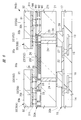
- FIG. 5 is an enlarged cross-sectional view of a portion A in FIG.
- FIG. 6 is an enlarged cross-sectional view of a portion B in FIG.
- the wiring board 10 shown in FIGS. 1 to 5 is a board provided with a transmission path for supplying electric signals and potentials between the semiconductor device PKG1 and the mounting board 60 (see FIG. 4).
- the wiring board 10 has a plurality of wiring layers (eight layers in the example shown in FIG. 3) that electrically connect the upper surface 10t side and the lower surface 10b side.
- the plurality of wirings 13 provided in each wiring layer are covered with an insulating layer 14 that insulates between the plurality of wirings 13 and between adjacent wiring layers.
- the wiring substrate 10 shown in FIG. 3 has a plurality of laminated insulating layers 14, and the middle insulating layer 14 is a core in which a fiber material such as glass fiber is impregnated with a resin material such as an epoxy resin, for example. It is a layer (core material).
- the insulating layers 14 formed on the upper surface and the lower surface of the core layer are formed by, for example, a buildup method.
- a so-called coreless substrate that does not have the insulating layer 14 serving as a core layer may be used.
- the wiring board 10 includes via wirings 15 which are provided between the wiring layers and are interlayer conductive paths connecting the stacked wiring layers in the thickness direction.
- a plurality of bonding pads (terminals, chip mounting surface side terminals, electrodes) 16 are formed on the upper surface 10 t of the wiring substrate 10.
- the wiring 13 provided in the uppermost wiring layer is formed integrally with the bonding pad 16.
- the bonding pad 16 can be considered as a part of the wiring 13.
- the portion exposed from the insulating film 17 on the upper surface 10t of the wiring substrate 10 is defined as the bonding pad 16 and the portion covered with the insulating film 17 is defined as the wiring 13. Can do.
- solder connection pads 12 are formed on the lower surface 10b of the wiring board 10. Solder balls 11 are connected to each of the plurality of lands 12, and the mounting substrate 60 and the semiconductor device PKG1 shown in FIG. 4 are electrically connected via the solder balls 11 shown in FIG. That is, the plurality of solder balls 11 function as external connection terminals of the semiconductor device PKG1.
- the plurality of solder balls 11 and the plurality of lands 12 are electrically connected to the plurality of bonding pads 16 on the upper surface 10 t side via the plurality of wirings 13 of the wiring substrate 10.
- the wiring 13 provided in the lowermost wiring layer (the wiring layer on the lowermost surface 10 b side) is formed integrally with the land 12.
- the land 12 can be considered as a part of the wiring 13.
- the portion exposed from the insulating film 17 on the lower surface 10 b of the wiring substrate 10 can be defined as the land 12, and the portion covered with the insulating film 17 can be defined as the wiring 13. .
- solder balls 11 are not connected to the lands 12, and each of the lands 12 is exposed from the insulating film 17 on the lower surface 10 b of the wiring substrate 10.
- a thin solder film may be connected instead of the ball-shaped solder ball 11, and this solder film may function as an external connection terminal.
- the upper surface 10 t and the lower surface 10 b of the wiring substrate 10 are covered with an insulating film (solder resist film) 17.
- the wiring 13 formed on the upper surface 10 t of the wiring substrate 10 is covered with an insulating film 17.
- An opening is formed in the insulating film 17, and at least a part (bonding region) of the plurality of bonding pads 16 is exposed from the insulating film 17 in the opening.
- the wiring 13 formed on the lower surface 10 b of the wiring substrate 10 is covered with an insulating film 17.
- An opening is formed in the insulating film 17, and at least a part of the plurality of lands 12 (joined portions with the solder balls 11) is exposed from the insulating film 17 in the opening.
- the semiconductor device PKG1 includes an interposer 20A mounted on the wiring board 10.
- the interposer 20 ⁇ / b> A is a relay board that is interposed between the wiring board 10 and the plurality of semiconductor chips 30.
- the interposer 20A includes a silicon substrate (base material) 21 having a main surface 21t and a plurality of wiring layers M1, M2, and M3 arranged on the main surface 21t.
- a layer in which a plurality of surface electrodes 25 are formed is regarded as a wiring layer M4, in the example shown in FIG. 5, four wiring layers are laminated.
- a plurality of wirings (conductor patterns) 22 are formed in each of the plurality of wiring layers M1, M2, and M3.
- the plurality of wirings 22 are covered with an insulating layer 23 that insulates between the plurality of wirings 22 and between adjacent wiring layers.
- the insulating layer 23 is an inorganic insulating layer made of an oxide of a semiconductor material such as silicon oxide (SiO).
- a plurality of surface electrodes (electrode pads, terminals) 25 are formed on the wiring layer M3 of the interposer 20A. A part of each of the plurality of surface electrodes 25 is exposed from the passivation film 26 which is a protective insulating film on the upper surface 20t of the interposer 20A.
- the surface electrode 25 is electrically connected to an electrode (surface electrode, pad) 33 of the semiconductor chip 30 via a bump electrode 35 connected to an exposed portion of the surface electrode 25.
- a plurality of backside electrodes (electrodes, pads, terminals) 27 are formed on the lower surface 20b of the interposer 20A.
- the plurality of back surface electrodes 27 are exposed on the lower surface 20b of the interposer 20A located on the opposite side of the main surface 21t of the silicon substrate 21.
- the back electrode 27 is electrically connected to the bonding pad 16 of the wiring board 10 via the bump electrode 28 connected to the back electrode 27.
- the interposer 20A includes a plurality of through electrodes 24 that penetrate the silicon substrate 21 in the thickness direction (the direction from one surface to the other surface of the main surface 21t and the lower surface 20b).
- the plurality of through electrodes 24 are conductive paths formed by embedding a conductor such as copper (Cu) in a through hole formed to penetrate the silicon substrate 21 in the thickness direction.
- Each of the plurality of through electrodes 24 has one end connected to the back electrode 27 and the other end connected to the wiring 22 of the wiring layer M1. That is, the plurality of front surface electrodes 25 and the plurality of back surface electrodes 27 of the interposer 20 ⁇ / b> A are electrically connected via the plurality of wirings 22 and the plurality of through electrodes 24, respectively.
- the wiring board 10 described above is a support base material for the semiconductor device PKG1. In order to exhibit the function as a support substrate, it is preferable to improve rigidity and strength. For this reason, it is difficult to finely process the plurality of wirings 13 formed on the wiring board 10.
- the interposer 20A is a relay board mounted on the wiring board 10, the rigidity and strength of the board may be lower than that of the wiring board 10. For this reason, the wiring density of the plurality of wirings 22 formed in the interposer 20 ⁇ / b> A can be improved as compared with the wirings 13 of the wiring board 10.
- the interposer 20A of the present embodiment has a silicon substrate (base material) 21 that is a semiconductor substrate as shown in FIG. 5, and a plurality of wiring layers M1, M2, M3 on the main surface 21t of the silicon substrate 21.
- a silicon substrate (base material) 21 that is a semiconductor substrate as shown in FIG. 5, and a plurality of wiring layers M1, M2, M3 on the main surface 21t of the silicon substrate 21.
- the wiring density can be improved by using the same process as the process of forming the wirings on the semiconductor wafer.
- the thickness of each wiring layer and the distance between wiring layers are also reduced.
- the thickness of the wiring layers M1, M2, and M3 shown in FIGS. 5 and 6, that is, the thickness of each of the plurality of wirings 22 is thinner than the thickness of the wiring 13 of the wiring board 10.
- the wiring 13 of the wiring board 10 and the wiring 22 of the interposer 20 ⁇ / b> A are shown in one figure, so that the thickness of the wiring 13 is less than twice the thickness of the wiring 22.
- the thickness of the wiring 13 is several times to several tens of times the value of the thickness of the wiring 22 described above.
- the separation distances of the wiring layers M1, M2, and M3 and the separation distance between the main surface 21t of the silicon substrate 21 and the wiring layer M1 are smaller than the thickness of the wiring 22.
- the distance between each of the wiring layers M1, M2, and M3 and the distance between the main surface 21t of the silicon substrate 21 and the wiring layer M1 are about half of the thickness of the wiring 22 formed in the wiring layers M1, M2, and M3. It is. Note that the distance between the uppermost wiring layer M4 on which the plurality of surface electrodes 25 are formed and the wiring layer M3 is larger than the distance between the wiring layers M1, M2, and M3. For example, the distance between the wiring layer M4 and the wiring layer M3 is about the same as the thickness of the wiring 22.
- the interposer 20A can improve the wiring density as compared with the wiring board 10, it is particularly effective when increasing the number of signal transmission paths connecting the plurality of semiconductor chips 30.
- the interposer 20A is provided to form the wiring board 10. The number of wirings 13 (see FIG. 3) to be performed can be reduced.
- the silicon substrate 21 widely used in the semiconductor wafer manufacturing process is used as a base material. Therefore, the silicon substrate 21 shown in FIG. 5 uses silicon, which is a semiconductor material, as a base material (main component).
- a semiconductor substrate used for manufacturing a semiconductor chip is generally doped with an impurity element constituting p-type or n-type conductive characteristics in a semiconductor material as a base material. For this reason, when a general-purpose semiconductor wafer is used as the silicon substrate 21, the silicon substrate 21 contains an impurity element constituting p-type or n-type conductive characteristics.
- silicon substrate 21 of the present embodiment various modifications can be applied to the silicon substrate 21 of the present embodiment.
- a semiconductor material other than silicon may be used as a base material for the semiconductor substrate.
- a semiconductor in which no impurity element is doped in a semiconductor material can be used as a semiconductor substrate.
- the semiconductor device PKG1 includes a plurality of semiconductor chips 30 mounted on the upper surface 20t of the interposer 20A.
- Each of the plurality of semiconductor chips 30 includes a silicon substrate (base material) 31 having a main surface 31t, and a wiring layer 32 disposed on the main surface 31t.
- one wiring layer 32 is shown for the sake of clarity.
- the wiring layer 32 shown in FIGS. 5 and 6 includes the wiring layers M1, M2, and the like of the interposer 20A.
- a plurality of wiring layers that are thinner than M3 are stacked.
- a plurality of wirings are formed in each of the plurality of wiring layers 32.
- the plurality of wirings are covered with an insulating layer that insulates between the plurality of wirings and between adjacent wiring layers.
- the insulating layer is an inorganic insulating layer made of an oxide of a semiconductor material such as silicon oxide (SiO).
- a plurality of semiconductor elements such as transistor elements or diode elements are formed on the main surface 31t of the silicon substrate 31 included in each of the plurality of semiconductor chips 30.
- the plurality of semiconductor elements are electrically connected to the plurality of electrodes 33 formed on the surface 30 t side through the plurality of wirings of the wiring layer 32.
- each of the plurality of semiconductor chips 30 is mounted on the upper surface 20t of the interposer 20A with the surface 30t and the upper surface 20t of the interposer 20A facing each other.
- a mounting method is called a face-down mounting method or a flip-chip connection method.
- the semiconductor chip 30 and the interposer 20A are electrically connected as follows.
- a plurality of electrodes (surface electrodes, pads, terminals) 33 are formed on the wiring layer 32 of the semiconductor chip 30. A part of each of the plurality of electrodes 33 is exposed from the passivation film 34 which is a protective insulating film on the surface 30 t of the semiconductor chip 30.
- the electrode 33 is electrically connected to the surface electrode 25 of the interposer 20 ⁇ / b> A via the bump electrode 35 connected to the exposed portion of the electrode 33.
- a part of the plurality of transmission paths connected to the memory chip 30A is not connected to the wiring board 10, and the logic chip 30B is connected via the interposer 20A. Connected to.
- the data line DQ and the control signal line CMD are electrically separated from the wiring board 10.
- the power supply line VD2 and the reference potential line VS1 for supplying the power supply potential for driving the circuit of the memory chip 30A are electrically connected to the wiring board 10. ing.
- the reference potential line VS2 used for reference of the signal line may be separated from the wiring board 10.
- each of the plurality of data lines DQ is designed to transmit a data signal at a transmission rate of 1 Gbps (1 gigabit per second) or more.
- high clocking In order to increase the transmission speed of each of the plurality of signal transmission paths, it is necessary to increase the number of transmissions per unit time (hereinafter referred to as high clocking).
- bus width expansion As another method for improving the signal transmission speed between the logic chip 30B and the memory chip 30A, there is a method of increasing the amount of data transmitted at a time by increasing the width of the data bus of the internal interface (Hereinafter referred to as bus width expansion). Further, there is a method of applying a combination of the above-described bus width expansion and high clock. In this case, many high-speed signal transmission paths are required. Therefore, a method of electrically connecting the logic chip 30B and the memory chip 30A via the interposer 20A as in the present embodiment is effective.
- the memory chip 30A shown in FIG. 4 is a so-called wide I / O memory having a data bus width of 512 bits or more.
- the memory chip 30A includes, for example, four channels having a data bus width of 128 bits, and the total bus width of the four channels is 512 bits.
- the number of transmissions per unit time of each channel is increased to a high clock, for example, 1 Gbps or more.
- the present inventor has a problem from the viewpoint of signal transmission reliability. I found out.
- signal loss transmission loss
- FIG. 7 is an explanatory diagram showing the relationship between the operating frequency of the signal transmission path and the signal loss.
- FIG. 8 is a cross-sectional view of a principal part schematically showing a state where a current flows through the silicon substrate.
- the frequency at which a signal is transmitted is shown logarithmically on the horizontal axis, and the degree of signal loss at each frequency is shown on the vertical axis.
- the operating frequency band of the data line DQ shown in FIG. 4 is shown as a frequency band F2
- the operating frequency band of the control signal line CMD is shown as a frequency band F1.
- the display electrode 25 is indicated by a dotted line in order to clearly show that the wiring layer M ⁇ b> 4 is a layer for forming the surface electrode 25.
- the silicon substrate 21 shown in FIG. 8 contains an impurity element that constitutes p-type or n-type conductive characteristics, like the silicon substrate 21 included in the interposer 20A of the present embodiment shown in FIG.
- FIG. 9 is an enlarged plan view showing a region around the logic chip and the memory chip shown in FIG. 1 in an enlarged manner.
- FIG. 10 is a cross-sectional view of the main part showing an example of the arrangement of wirings according to the type of transmission target in the cross section taken along the line AA in FIG.
- a plurality of wirings 22 that electrically connect the memory chip 30 ⁇ / b> A and the logic chip 30 ⁇ / b> B, and a plurality of surface electrodes 25 of the interposer 20 ⁇ / b> A connected to both ends of the wiring 22 are indicated by dotted lines.
- FIG. 9 schematically shows that the memory chip 30A and the logic chip 30B are electrically connected via a plurality of wirings 22.
- FIG. 10 is a cross-sectional view, but in order to identify the type of transmission path formed by the plurality of wirings 22, different patterns are given depending on the type of transmission target.
- hatching is applied to the data signal wiring 22DQ constituting a part of the data line DQ shown in FIG. 4, and a dot pattern is applied to the control signal wiring 22CMD constituting a part of the control signal line CMD shown in FIG. , Respectively.
- the reference potential wiring 22VS serving as a reference potential transmission path is blank without any pattern.
- the silicon substrate 21 is blank without any pattern.
- the display electrode 25 is indicated by a dotted line in order to clearly show that the wiring layer M4 is a layer for forming the surface electrode 25.
- the memory chip 30A and the logic chip 30B included in the semiconductor device PKG1 of the present embodiment are electrically connected through a plurality of wirings 22 of the interposer 20A.
- the wiring 22 that electrically connects the memory chip 30A and the logic chip 30B is mainly disposed in a region 22A of the interposer 20A sandwiched between the memory chip 30A and the logic chip 30B.
- the wiring structure in the region 22A shown in FIG. 9 may be examined, and the wiring structure in other regions is not particularly limited.
- a region to which the plurality of wirings 22 electrically connecting the memory chip 30A and the logic chip 30B are connected is a plurality of regions connected to both ends of the plurality of wirings 22 as shown in FIG. This is a region 22B between the front surface electrodes 25.
- each of the plurality of surface electrodes 25 connected to both ends of the plurality of wirings 22 is often formed close to the opposite sides of the adjacent semiconductor chip. .
- most of the region 22B overlaps with the region 22A. Therefore, at least by improving the wiring structure of the region 22A, the reliability of signal transmission between adjacent semiconductor chips can be improved.
- the wiring in the region 22B In some cases, it is preferable to consider the structure.
- the interposer 20A included in the semiconductor device PKG1 of the present embodiment includes a wiring layer M1, a wiring layer M2 that is farther from the main surface 21t of the silicon substrate 21 than the wiring layer M1, and a wiring layer M2. Also includes a wiring layer M3 separated from the main surface 21t.
- the ratio (occupancy) of the reference potential wiring 22VS constituting a part of the reference potential transmission path among the plurality of wirings 22 is the reference potential wiring in the wiring layer M3.
- the ratio of 22VS is larger than the ratio (occupancy) of the reference potential wiring 22VS in the wiring layer M1.
- the ratio of the reference potential wiring 22VS in the wiring layer M1 (or wiring layer M3) is the ratio of the reference potential wiring 22VS to the total plane area of the conductor patterns formed in the wiring layer M1 (or wiring layer M3). Occupancy rate.
- the ratio of the signal wiring in the wiring layer M1 (or wiring layer M3) means the occupation ratio of the signal wiring with respect to the total plane area of the conductor pattern formed in the wiring layer M1 (or wiring layer M3). To do.
- the ratio of a certain type of wiring in a certain wiring layer it has the same meaning as described above, unless it is explained that it is used in a different meaning.
- the ratio (occupancy) of the signal wiring (data signal wiring 22DQ and control signal wiring 22CMD) that constitutes a part of the signal transmission path among the plurality of wirings 22.
- the ratio of the signal wiring in the wiring layer M1 is larger than the ratio (occupancy) of the signal wiring in the wiring layer M3.
- the configuration of the interposer 20A of the present embodiment can also be expressed as follows. That is, in the wiring layer M1 having a relatively short distance to the main surface 21t of the silicon substrate 21, signal wiring (data signal wiring 22DQ or control signal wiring 22CMD) is mainly provided, and the main surface of the silicon substrate 21 is provided. In the wiring layer M3 whose distance up to 21t is relatively long, the reference potential wiring 22VS is mainly provided. Thereby, the following effects are acquired.
- the distribution of the electromagnetic field generated when a signal is passed through the wiring 22 can be controlled by the reference potential wiring 22VS.
- the electromagnetic field is mainly the same as the wiring 22. It becomes distributed in layers or above. For this reason, even when the signal current flowing through the wiring 22 is a high-frequency signal, signal loss due to the current CF (see FIG. 8) flowing through the silicon substrate 21 can be suppressed.
- the reference potential supplied to the reference potential wiring 22VS shown in FIG. 10 is the same potential as the potential (eg, ground potential) supplied to the reference potential line VS1 shown in FIG.
- controlling the distribution of the electromagnetic field generated when a signal is passed through the wiring 22 may be a transmission path to which a potential other than the ground potential is supplied.
- the power supply potential supplied for driving the input / output circuit shown in FIG. 4 may be used.
- FIG. 11 is a cross-sectional view of the main part showing an example of the arrangement ratio for each type of transmission target in each wiring layer of the interposer, which is an examination example different from FIG.
- the interposer 20H shown in FIG. 11 is different from the interposer 20A shown in FIG. 10 in the following points. That is, in the wiring layer M1 that is relatively close to the main surface 21t of the silicon substrate 21, the reference potential wiring 22VS is mainly provided, and the wiring layer that is relatively far from the main surface 21t of the silicon substrate 21. In M3, signal wiring is mainly provided. In other words, in the interposer 20H shown in FIG. 11, the reference potential wiring 22VS is provided between the plurality of signal wirings and the silicon substrate 21.
- the inventor of the present application provides a reference potential wiring 22VS between a plurality of signal wirings and the silicon substrate 21, thereby shielding an electromagnetic field generated when a high frequency signal flows through the signal wiring by the reference potential wiring 22VS.
- a reference potential wiring 22VS between a plurality of signal wirings and the silicon substrate 21, thereby shielding an electromagnetic field generated when a high frequency signal flows through the signal wiring by the reference potential wiring 22VS.
- the shield becomes a mesh shape for the sake of manufacturing, and the shielding effect is diminished, so that it is difficult to suppress signal loss compared to the interposer 20A shown in FIG. I understood. The reason for this will be described below.
- CMP Chemical Mechanical Polishing
- the reference potential wiring 22VS In order to shield the electromagnetic field generated when the high frequency signal flows through the signal wiring (for example, the data signal wiring 22DQ) shown in FIG. 11 by the reference potential wiring 22VS, the reference potential wiring provided in the wiring layer M1. Although it is necessary to increase the area of 22VS, it is difficult to form the planar shape of the reference potential wiring 22VS into a sheet shape. For this reason, the electromagnetic field described above wraps around the silicon substrate 21 through the gap between the conductor patterns constituting the reference potential wiring 22VS. That is, it is difficult to obtain a sufficient shielding effect by the reference potential wiring 22VS.
- the reference potential wiring 22VS is used as a conductor pattern for controlling the distribution of the electromagnetic field. Therefore, for example, the planar shape of the reference potential wiring 22VS shown in FIG. 10 is a linear pattern extending from one of the memory chip 30A and the logic chip 30B to the other like the wiring 22 shown by a dotted line in FIG. Even in some cases, signal loss can be suppressed. For example, even if the planar shape of the reference potential wiring 22VS shown in FIG. 10 is a mesh pattern, signal loss can be suppressed.
- the reference potential wiring 22VS shown in FIG. 10 need not be used exclusively for controlling the distribution of the electromagnetic field. Therefore, a part of the electromagnetic field may be shielded by the reference potential wiring 22VS. Further, the reference potential wiring 22VS shown in FIG. 10 may constitute a part of the return current path of the high-speed signal.
- the expression “the ratio of A is greater than the ratio of B” includes the case where the ratio of B is 0%.
- the expression “the ratio of A is smaller than the ratio of B” includes the case where the ratio of A is 0%.
- the ratio of A is greater (or less than the ratio of B) is used in the present specification, the same meaning is used.
- the reference potential wiring 22VS is not formed in the wiring layer M1, and the ratio of the signal wiring in the wiring 22 formed in the wiring layer M1 in the region 22A (see FIG. 9) is 100%.
- the reference potential wiring 22VS may be formed in the wiring layer M1 in the region 22A (see FIG. 9).
- the ratio (occupancy) of the reference potential wiring 22VS constituting a part of the reference potential transmission path among the plurality of wirings 22 is the ratio of the reference potential wiring 22VS in the wiring layer M3. Is larger than the ratio (occupancy) of the reference potential wiring 22VS in the wiring layer M1.
- the wiring structure of the interposer 20A shown in FIG. 10 can also be expressed as follows.
- the ratio of the reference potential wiring (reference potential conductor) 22VS constituting a part of the reference potential transmission path is the ratio of the signal transmission path. It is smaller than the proportion of the signal wiring (data signal wiring 22DQ or control signal wiring 22CMD) constituting a part.
- the ratio of the reference potential wiring 22VS that forms part of the reference potential transmission path is the ratio of the signal wiring that forms part of the signal transmission path. More than
- signal wiring data signal wiring 22DQ or control signal wiring 22CMD
- the reference potential wiring 22VS is mainly provided in the wiring layer M3 that is relatively far from the main surface 21t of the silicon substrate 21. Therefore, an electromagnetic field generated when high-speed signal transmission is performed is mainly distributed in the same layer as or above the wiring 22. As a result, according to the above configuration, signal loss can be suppressed.
- a control signal wiring 22CMD for transmitting a signal in a relatively low frequency band F1 (see FIG. 7) and a control signal are connected to the plurality of signal wirings.
- control data signals such as an address signal and a command signal transmitted through the control signal line CMD are transmitted at a frequency equal to or less than half that of the data signal transmitted through the data line DQ.
- the degree of signal loss is lower in the frequency band F1 than in the frequency band F2.
- the data signal wiring 22DQ transmitted at high frequency is preferably provided in the wiring layers M2 and M3, which are relatively far from the main surface 21t of the silicon substrate 21.
- the distance between the wiring layer M1 and the main surface 21t of the silicon substrate 21 is smaller than the thickness of the wiring 22 of the wiring layer M1, and is, for example, about 0.5 ⁇ m to 0.6 ⁇ m.
- the thickness of the insulating layer 23 between the wiring layer M1 and the main surface 21t of the silicon substrate 21 is smaller than the thickness of the wiring 22 of the wiring layer M1, for example, about 0.5 ⁇ m to 0.6 ⁇ m. . Therefore, from the viewpoint of reducing signal loss, it is particularly preferable that the data signal wiring 22DQ is not formed in the wiring layer M1, as shown in FIG.
- the data signal wiring 22DQ is formed in the wiring layer M1 in order to increase the number of signal lines may be considered.
- the ratio of the control signal wiring 22CMD in which the signal (control signal) is transmitted in the first frequency band (for example, the frequency band F1). Is larger than the ratio of the data signal wiring 22DQ in which a signal (data signal) is transmitted in a second frequency band (for example, frequency band F2) higher than the first frequency band.
- the ratio of the control signal wiring 22CMD that transmits a signal (control signal) in the first frequency band is the second It is less than the ratio of the data signal wiring 22DQ through which a signal (data signal) is transmitted in a frequency band (for example, frequency band F2).
- the expression “the ratio of A is greater than the ratio of B” includes the case where the ratio of B is 0%.
- the expression “the ratio of A is smaller than the ratio of B” includes the case where the ratio of A is 0%.
- the data signal wiring 22DQ is not formed in the wiring layer M1, and the control signal wiring CMD is included in the wiring 22 formed in the wiring layer M1 in the region 22A (see FIG. 9). The percentage is 100%.
- the data signal wiring 22DQ is not formed in the wiring layers M2 and M3.
- the return current path (return path) of the data signal transmitted through the data line DQ shown in FIG. 4 can be shortened.
- the return current path for connecting the semiconductor chips 30 is preferably provided at a position close to the semiconductor chip 30.
- the reference potential line VS2 for reference shown in FIG. 4 is supplied with, for example, a ground potential, which is also a return current path for a data signal transmitted through the data line DQ.
- the reference potential wiring 22VS shown in FIG. 10 forms part of the reference reference potential line VS2
- the reference potential wiring 22VS is provided at a position close to the semiconductor chip 30 shown in FIG. Can be shortened.
- the reference potential wiring 22VS is mainly formed in the wiring layer M3 close to the surface electrode 25. Therefore, the transmission distance of the reference signal can be shortened compared to the interposer 20H shown in FIG.
- the wiring layer M2 closer to the surface electrode 25 than the wiring layer M1 is mainly formed with the data signal wiring 22DQ transmitted mainly in the high frequency band F2 (see FIG. 7). ing. For this reason, even when the reference potential wiring 22VS is mainly formed in the wiring layer M3, an increase in the transmission distance of the high-frequency signal can be suppressed.
- FIG. 12 is an enlarged plan view of a portion B shown in FIG.
- the outline of the electrode 33A of the memory chip 30A, the electrode 33B of the logic chip 30B, and the surface electrode 25 of the interposer 20A is indicated by dotted lines in order to show the planar shape of the connection portion between the semiconductor chip 30 and the interposer 20A.
- the contour of the electrode 33A and the contour of the surface electrode 25 connected to the electrode 33A, and the contour of the electrode 33B and the contour of the surface electrode 25 connected to the electrode 33B are substantially overlapped. ing.
- the passivation film 26 that covers the surface of the interposer 20A is provided with a plurality of openings, and a part of the surface electrode 25 is exposed from the passivation film 26 in the openings.
- the outline of the opening that exposes a part of the surface electrode 25 of the interposer 20A is indicated by a solid circle.
- the logic chip 30B includes an external interface circuit IF1 that inputs / outputs signals to / from the external device 40 in addition to the internal interface circuit IF2 that inputs / outputs signals to / from the memory chip 30A.
- the number of signal lines (signal line SIG, data line DQ, and control signal line CMD) connected to the logic chip 30B is the same as the number of signal lines (data line DQ and control signal line CMD) connected to the memory chip 30A. More than the number.
- the transmission speed of the signal line SIG shown in FIG. 4 is faster than the transmission speed of the data line DQ. For this reason, the signal line SIG connected to the logic chip 30B or the power supply lines VD1 and VS1 that supply the drive voltage for the logic chip 30B needs to have a strengthened transmission path.
- FIGS. 5 and 6 in the case of the plurality of electrodes 33 included in the logic chip 30 ⁇ / b> B, a plurality of (two in FIG. 6) through-electrodes with respect to one electrode 33. 24 is connected.
- FIG. 6 in the case of the plurality of electrodes 33 included in the memory chip 30 ⁇ / b> A, one through electrode 24 is connected to one electrode 33. That is, the number of through electrodes 24 connected to each of the plurality of electrodes 33 of the logic chip 30B is larger than the number of through electrodes 24 connected to each of the plurality of electrodes 33 of the memory chip 30A.
- the signal line SIG connected to the logic chip 30B shown in FIG. 4 or the power supply lines VD1 and VS1 for supplying a driving voltage for the logic chip 30B preferably have the following configuration from the viewpoint of strengthening the transmission path.
- the area of the surface electrode 25B of the electrode 33B of the logic chip 30B is preferably larger than the area of the surface electrode 25A of the electrode 33A of the memory chip 30A.
- the diameter D1 of the electrode (surface electrode, pad) 33B of the logic chip 30B is larger than the diameter D2 of the electrode (surface electrode, pad) 33A of the memory chip 30A.
- FIG. 12 shows a case where the planar shape of the electrode 33A and the electrode 33B is a quadrangle, and the diagonal of the quadrangle is the value of the diameter D2 or the diameter D1.
- the planar shape of the electrode 33A and the electrode 33B may be a shape other than a quadrangle.
- the diameter of the circle is a value of the diameter D2 or the diameter D1.
- the separation distance P1 between the adjacent electrodes 33B is larger than the separation distance P2 between the adjacent electrodes 33A among the plurality of electrodes 33A.
- the separation distance P1 and the separation distance P2 described above are the smallest of the separation distances. Evaluate by value.
- the diameter of the surface electrode 25 of the interposer 20A connected to the electrode 33 of the logic chip 30B may be increased as shown in FIG. it can.
- a plurality (two in FIG. 6) of through electrodes 24 can be connected to one electrode 33 of the logic chip 30B.
- FIG. 13 is an enlarged cross-sectional view of a semiconductor device which is a modification to FIG.
- FIG. 14 is a modified example of FIG. 12, and is an enlarged plan view of the semiconductor device shown in FIG.
- FIG. 15 is a modification of FIG. 10 and is a cross-sectional view of the main part showing an example of the arrangement ratio for each type of transmission target in each wiring layer of the interposer shown in FIGS.
- FIG. 13 is an enlarged cross-sectional view of a semiconductor device which is a modification to FIG.
- FIG. 14 is a modified example of
- FIG. 16 is a cross-sectional view of a main part showing another modification example of FIG.
- FIG. 17 is an enlarged plan view showing a structure example of the wiring layer below the layer on which the plurality of surface electrodes of the interposer shown in FIG. 6 are formed.
- FIG. 14 in order to show the planar shape of the connecting portion between the semiconductor chip 30 and the interposer 20B, the surface electrode 25A of the interposer 20B connected to the memory chip 30A, the surface electrode 25B of the interposer 20B connected to the logic chip 30B, and The outline of the reference potential wiring 22VS is indicated by a dotted line.
- the passivation film 26 (see FIG. 13) covering the surface of the interposer 20B is provided with a plurality of openings, and a part of the surface electrode 25 is exposed from the passivation film 26 in the openings.
- the outline of the opening that exposes a part of the surface electrode 25 of the interposer 20B is indicated by a solid circle, and the type of transmission path that each exposed portion constitutes is indicated with an underline.
- a pattern (dot pattern) is provided on the reference potential wiring 22VS so that the boundary between the conductor pattern constituting the reference potential wiring 22VS and the conductor pattern constituting another transmission path can be easily seen. It is attached.
- the semiconductor device PKG2 shown in FIG. 13 is different from the semiconductor device PKG1 shown in FIG. 6 in the wiring layout of the interposer 20B. Specifically, in the interposer 20B included in the semiconductor device PKG2, the reference potential wiring 22VS that constitutes a part of the reference potential transmission path is formed in the uppermost wiring layer M4 on which the plurality of surface electrodes 25 are formed. This is different from the interposer 20A shown in FIG.
- the interposer 20B differs from the interposer 20A in that many of the reference potential wirings 22VS are formed in the same layer as the plurality of surface electrodes 25.
- a reference potential wiring 22VS constituting a part of a reference potential transmission path in the wiring 22 arranged in the wiring layer M4 of the interposer 20B. This ratio is larger than the ratio of the signal wiring constituting a part of the signal transmission path. In the example shown in FIG. 14, no conductor pattern other than the reference potential wiring 22VS is formed in the region 22A.
- the reference potential line VS2 (in the region where the surface electrode 25 is not disposed in the uppermost layer, that is, the wiring layer M4 which is the wiring layer formed farthest from the main surface 21t of the silicon substrate 21.
- a reference potential wiring 22VS that constitutes FIG. 14) is provided.
- the surface electrode 25 and the reference potential wiring 22VS constituting the reference potential line VS2 of the interposer 20B are integrally formed.
- the surface electrode 25 and the reference potential wiring 22VS constituting the reference potential line VS2 are connected to each other. Therefore, in the region 22A of the uppermost wiring layer M4 of the interposer 20B, the reference potential wiring 22VS is formed so as to cover most of the wiring layer M3 (see FIG. 13), and a part of the reference potential wiring 22VS is formed. It functions as a surface electrode 25 for transmitting a reference potential.
- a surface electrode 25 constituting a transmission path other than the reference potential line VS2, for example, the signal line SG shown in FIG. 4 or the transmission path for the power supply lines VD1 and VD2 is arranged. An opening is formed in the reference potential wiring 22VS2 at a position, and a surface electrode 25 is formed in the opening.
- the interposer 20B since the wiring layer M4 is used as a reference potential transmission path, the number of wirings of the data signal wiring 22DQ which is a high-speed transmission path in the wiring layer M2 and the wiring layer M3 as shown in FIG. Can be increased.
- the reference potential wiring 22VS is not formed in each of the wiring layer M2 and the wiring layer M3, and only the data signal wiring 22DQ is arranged. .
- the interposer 20B shown in FIG. 15 can increase the number of data signal wirings 22DQ as compared to the interposer 20A shown in FIG.
- the reference potential wiring 22VS may be disposed in the wiring layer M2 or the wiring layer M3 as a modification to the example shown in FIG. Even in this case, the number of data signal lines 22DQ provided in each of the wiring layer M2 and the wiring layer M3 can be increased as compared with the interposer 20A shown in FIG. Further, since the control signal wiring 22CMD is mainly provided in the wiring layer M1, the number of the control signal wirings 22CMD can be sufficiently secured. Further, as a modification of the example shown in FIG. 15, the control signal wiring 22CMD may be arranged in the wiring layer M2 or the wiring layer M3.
- the wiring layer M4 When the wiring layer M4 is used as a supply space for the reference potential wiring 22VS as in the interposer 20C included in the semiconductor device PKG3 shown in FIG. 16, a plurality of data signal wirings provided in the wiring layer M2 and the wiring layer M3.
- the separation distance of 22DQ can be increased.
- the reference potential wiring 22VS is formed in the wiring layer M4, and the high-speed signal transmission path wiring has a large distance from other wirings.
- the data signal wiring 22DQ provided in the wiring layer M2 is provided so as not to overlap the control signal wiring 22CMD formed in the wiring layer M1 in the thickness direction.
- the data signal wiring 22DQ provided in the wiring layer M2 is arranged so as not to overlap with the control signal wiring 22CMD formed in the wiring layer M1 in the thickness direction.
- crosstalk between the transmission path of the data signal and the transmission path of other signals can be reduced. That is, the interposer 20 ⁇ / b> C illustrated in FIG. 16 is a configuration example when importance is attached to suppression of crosstalk of a wiring that performs high-speed signal transmission.
- the wiring layer M2 is provided between the data signal wiring 22DQ formed in the wiring layer M3 and the control signal wiring 22CMD formed in the wiring layer M1, it is formed in the wiring layer M3.
- the data signal wiring 22DQ and the control signal wiring 22CMD formed in the wiring layer M1 may overlap.
- the wiring layer M4 is the uppermost wiring layer forming the surface electrode 25 (see FIG. 6)
- the separation distance B34 between the wiring layer M3 and the wiring layer M4 is the separation distance B12 between the wiring layer M1 and the wiring layer M2.
- the distance B23 between the wiring layer M2 and the wiring layer M3 is larger. Therefore, the data signal wiring 22DQ formed in the wiring layer M3 and the reference potential wiring 22VS formed in the wiring layer M4 may overlap in the thickness direction.
- the reference potential wiring 22VS formed in the wiring layer M4 does not need to be flattened. For this reason, as shown in FIG. 14, it is not necessary to provide an opening other than the opening provided with the surface electrode 25 for the transmission path other than the reference potential, and a sheet-like conductive pattern that uniformly spreads is formed. can do.
- the reference potential wiring 22VS is not formed in the wiring layer M4, for example, the reference potential wiring 22VS having a large area may be formed in the wiring layer M3 like the interposer 20D of the semiconductor device PKG4 shown in FIG. it can.
- the reference potential wiring of the interposer 20 ⁇ / b> D shown in FIG. 23 has a larger area than the other wirings 22.
- the conductor pattern formed on the wiring layer M3 which is not the uppermost layer needs to form a plurality of surface electrodes 25 (see FIG. 10) on the wiring layer M4 which is the uppermost layer (see FIG. 10). Difficult to form.
- the reference potential wiring 22VS of the interposer 20D is a mesh-shaped conductor pattern (mesh pattern) in which a large number of linearly extending conductor patterns intersect each other.
- the reference potential wiring 22VS formed in a sheet shape has a lower electrical resistance than the reference potential wiring 22VS formed in a mesh shape as shown in FIG. Therefore, when the reference potential wiring 22VS is used as the reference reference potential line VS2 (see FIG. 4), the sheet-like reference potential wiring 22VS can reduce variations in signal line characteristics.
- the reference potential wiring 22VS is used as the reference potential line VS1 (see FIG. 4) for supplying a reference potential for driving voltage, the voltage drop is reduced by reducing the electric resistance of the reference potential wiring 22VS. Can be suppressed.
- the sheet-like reference potential wiring 22VS is easier to shield the electromagnetic field than the mesh-shaped reference potential wiring 22VS. Therefore, signal loss can be reduced.
- FIG. 18 is a modification of FIG. 10 and is a cross-sectional view of the main part showing an example of the distance between each wiring layer of the interposer and the arrangement ratio according to the type of transmission target.
- FIG. 19 is a cross-sectional view of a principal part showing another modified example with respect to FIG. 18 and 19 illustrate the silicon substrate 21, the wiring 22 constituting each wiring layer, and the surface electrode 25, and the insulating layer 23 covering each wiring layer, as in the enlarged sectional view shown in FIG. Illustration of (see FIG. 6) is omitted.
- a semiconductor device PKG5 shown in FIG. 18 is different from the semiconductor device PKG1 shown in FIG. 10 in the distance between the wiring layers of the interposer 20E.
- the interposer 20E included in the semiconductor device PKG5 is different from the interposer 20A shown in FIG. 10 in that the separation distance B23 between the wiring layer M3 and the wiring layer M2 is larger than the separation distance B12 between the wiring layer M2 and the wiring layer M1.
- the separation distance B34 between the wiring layer M4 and the wiring layer M3 is larger than the separation distance B23 between the wiring layer M3 and the wiring layer M2.
- the distance between the wiring layers of the interposer 20D increases as the distance from the silicon substrate 21 increases.
- the method of laminating the wiring layer on the silicon substrate 21 is performed by the following method, for example.
- the insulating layer 23 (see FIG. 6) is deposited on the main surface 21t of the silicon substrate 21 (insulating layer deposition step).
- an opening is formed in the insulating layer 23, and a conductor is embedded in the opening (conductor embedding step).
- the upper surface side of the insulating layer in which the conductor is embedded (surface away from the main surface 21t of the silicon substrate 21) is polished and planarized by, for example, CMP (polishing step).
- CMP polishing step
- a first wiring layer M1 is formed.
- an insulating layer is deposited on the first wiring layer M1 (insulating layer deposition step).
- the conductor embedding step, the polishing step, and the insulating layer deposition step are similarly repeated to laminate a plurality of wiring layers.
- the separation distance B23 and the separation distance B12 can be set to the same value as in the example shown in FIG. 10, but the modification example shown in FIG. Thus, the separation distance B23 may be larger than the separation distance B12.
- each of the above-described interposers 20A, 20B, 20C, and 20D uses the same process as the process of forming the wiring on the semiconductor wafer, so that the wiring density of the plurality of wirings 22 is, for example, the wiring of the wiring board 10 shown in FIG.
- the wiring density of 13 can be improved.
- the thickness of the wiring 22 is about 1 ⁇ m to 1.2 ⁇ m, and the distance between the stacked wiring layers M1, M2, and M3 is about half the thickness of the wiring 22.
- the design value of the characteristic impedance of the data line DQ shown in FIG. 4 is 50 ⁇ [Ohm]
- the wiring path using the data signal wiring 22DQ shown in FIGS. 10 and 18, and for the reference reference potential In the wiring path using the wiring 22VS it is preferable that each approaches 50 ⁇ .
- the capacitance component of the characteristic impedance defined by ⁇ is inversely proportional to the separation distance between the wiring layers. Therefore, when the separation distance is small, the capacitance component of the characteristic impedance becomes a large value. For this reason, if the wiring width is increased in order to reduce the above-described wiring resistance, the capacitance component of the characteristic impedance is further increased and the characteristic impedance becomes too smaller than 50 ⁇ . For this reason, the signal waveform becomes dull.
- the margin for adjusting the resistance component and the capacitance component of the characteristic impedance is small.
- the resistance component and the capacitance component of this characteristic impedance are in a trade-off relationship. If the margin for adjusting the resistance component and the capacitance component is reduced, it becomes difficult to adjust the characteristic impedance, and the impedance of the signal transmission path is set to a predetermined value. It becomes difficult to get close to the value.
- the separation distance B23 when the separation distance B23 is made larger than the separation distance B12, the above trade-off relationship is improved. That is, by increasing the separation distance B23 between the wiring layer M2 mainly provided with the data signal wiring 22DQ and the wiring layer M3 mainly provided with the reference potential wiring 22VS, the wiring width can be increased. The capacitance component of the characteristic impedance is difficult to decrease. As a result, the characteristic impedance in the wiring path using the data signal wiring 22DQ and in the wiring path using the reference potential wiring 22VS is easily brought close to, for example, 50 ⁇ .
- the separation distance B34 between the wiring layer M4 and the wiring layer M3 is larger than the separation distance B23 between the wiring layer M3 and the wiring layer M2. Since the wiring layer M4 is the uppermost wiring layer, the flatness of the uppermost surface electrode 25 may be lower than that of the wiring 22 of the other layers. For this reason, the separation distance B34 can be particularly increased. As shown in FIG. 18, when the wiring 22 is not formed in the wiring layer M4 in the region 22A (see FIG. 9), the magnitude of the separation distance B34 shown in FIG. The impact is small. However, when the reference potential wiring 22VS is formed in the wiring layer M4 like the interposer 20F included in the semiconductor device PKG6 of the modification shown in FIG. 19, the following effects are obtained.
- An interposer 20F shown in FIG. 19 has a reference that forms a reference potential line VS in a wiring layer M4 that is a wiring layer that is formed farthest from the main surface 21t of the silicon substrate 21 in the region 22A (see FIG. 9).
- a potential wiring 22VS is provided.
- the wiring layer M3 is mainly formed with a data signal wiring 22DQ through which a data signal is transmitted at a high speed (for example, the frequency band F2 shown in FIG. 7). That is, in the interposer 20E, the uppermost wiring layer M4 is mainly provided with the reference potential wiring 22VS, and the wiring layer M3 is provided with the data signal wiring 22DQ mainly transmitted at high speed.
- the above wiring structure can also be expressed as follows. That is, in the region 22A (see FIG. 9), in the wiring 22 arranged in the wiring layer M4 of the interposer 20F, the ratio of the reference potential wiring 22VS constituting a part of the reference potential transmission path is the ratio of the signal transmission path. More than the proportion of signal wiring that constitutes a part.
- the ratio of the control signal wiring 22CMD that transmits a signal (control signal) in the first frequency band (for example, the frequency band F1) is the second It is less than the ratio of the data signal wiring 22DQ through which a signal (data signal) is transmitted in a frequency band (for example, frequency band F2).
- the ratio of A is greater than the ratio of B includes the case where the ratio of B is 0%.
- the expression “the ratio of A is smaller than the ratio of B” includes the case where the ratio of A is 0%.
- the reference potential wiring 22VS is formed in a sheet shape in the wiring layer M4 (see FIG. 19) in the region 22A (see FIG. 14). Other wirings 22 are not formed.
- the control signal wiring 22CMD and the reference potential wiring 22VS are not formed in the wiring layer M3 in the region 22A (see FIG. 9).
- the reference potential wiring 22VS and the data signal wiring 22DQ are provided.
- the characteristic impedance of the signal transmission path changes depending on the separation distance of 22DQ.
- the distance between the data signal wiring 22DQ and the reference potential wiring 22VS is defined by the separation distance B34 between the wiring layer M4 and the wiring layer M3.
- the separation distance B34 is further larger than the separation distance B23, the value of the characteristic impedance of the data signal wiring 22DQ can be easily brought close to a predetermined value (for example, 50 ⁇ ).
- the uppermost wiring layer M4 can be thicker than the other wiring layers M1, M2, and M3. For this reason, the interposer 20F is preferable from the viewpoint of reducing the wiring resistance of the reference potential wiring 22VS.
- each of the plurality of data signal wirings 22DQ provided in the wiring layer M2 includes the plurality of wirings 22 provided in the wiring layer M1, and the wirings. It does not overlap with the plurality of wirings 22 provided in the layer M3 in the thickness direction. In this case, since the distance between the data signal wiring 22DQ and the other wiring 22 can be increased, the characteristic impedance of the signal transmission path can be easily brought close to a predetermined value.
- the separation distance B23 between the wiring layer M2 and the wiring layer M3 is larger than the separation distance B12. For this reason, the influence on the characteristic impedance due to the data signal wiring 22DQ of the wiring layer M2 and the data signal wiring 22DQ of the wiring layer M3 overlapping in the thickness direction can be reduced.
- the data signal wiring 22DQ of the wiring layer M2 and the data signal wiring 22DQ of the wiring layer M3 overlap in the thickness direction, so that the data signal is compared with the interposer 20C shown in FIG.
- the number of wiring lines 22DQ can be increased.
- FIG. 20 is an explanatory diagram showing an outline of the manufacturing process of the semiconductor device described with reference to FIGS.
- the interposer 20A shown in FIG. 10 the interposer 20B shown in FIG. 15, the interposer 20C shown in FIG. 16, the interposer 20D shown in FIG. 18, or the interposer 20E shown in FIG.
- a method for manufacturing the interposers 20A, 20B, 20C, 20D, and 20E (hereinafter, typically described as the interposer 20A in the description of the manufacturing process) is to prepare a silicon substrate 21 that is a semiconductor wafer, A plurality of wiring layers are stacked. For example, as described above, the wiring layer is laminated by repeating the insulating layer deposition step, the conductor embedding step, and the polishing step.
- a plurality of interposers 20A are collectively formed on a single semiconductor wafer. And after laminating
- a plurality of semiconductor chips 30 are mounted on the interposer 20A as shown in FIG.
- the plurality of semiconductor chips 30 are sequentially mounted so that the surfaces 30t of the plurality of semiconductor chips 30 and the upper surface 20t of the interposer 20A face each other.
- the mounting order is not particularly limited, when there is a difference in the thickness of the plurality of semiconductor chips 30, it is preferable to mount the semiconductor chip 30 having a relatively small thickness first.
- the memory chip 30A there is one memory chip 30A, but a stacked body in which a plurality of memory chips 30A are stacked may be used as the memory chip 30A.
- the stacked body of the memory chips 30A is likely to be thicker than the logic chip 30B. Therefore, it is preferable to mount the logic chip 30B first.
- the plurality of electrodes 33 of the semiconductor chip 30 and the plurality of surface electrodes 25 of the interposer 20 ⁇ / b> A are electrically connected via the plurality of bump electrodes 35.
- the plurality of bump electrodes 35 are exposed, but an underfill resin (illustrated) is provided between the semiconductor chip 30 and the interposer 20 ⁇ / b> A so as to cover the periphery of the plurality of bump electrodes 35. May be omitted).
- the underfill resin is an insulating resin, and can cover the bump electrodes 35 by covering the periphery of the plurality of bump electrodes 35.
- the interposer mounting step as shown in FIG. 3, the wiring substrate 10 that is a package substrate is prepared, and the interposer 20 ⁇ / b> A on which a plurality of semiconductor chips 30 are mounted is mounted on the wiring substrate 10. In this step, mounting is performed so that the lower surface 20b of the interposer 20A and the upper surface 10t of the wiring board 10 face each other.
- the plurality of back electrodes of the interposer 20 ⁇ / b> A and the plurality of bonding pads 16 of the wiring substrate 10 are electrically connected via the bump electrodes 28.
- the plurality of bump electrodes 28 are exposed, but an underfill resin (illustrated) is provided between the interposer 20 ⁇ / b> A and the wiring board 10 so as to cover the periphery of the plurality of bump electrodes 28. May be omitted).
- the underfill resin is an insulating resin, and can cover the bump electrodes 28 by covering the periphery of the bump electrodes 28.
- the solder balls 11 are disposed on each of the plurality of lands 12 exposed on the lower surface 10b of the wiring board 10. Then, the plurality of solder balls 11 and the lands 12 are joined by heating the plurality of solder balls 11. Through this step, the plurality of solder balls 11 are electrically connected to the plurality of semiconductor chips 30 (logic chip 30B and memory chip 30A) via the wiring substrate 10.
- the technique described in this embodiment is not limited to a so-called BGA (Ball Grid Array) type semiconductor device in which solder balls 11 are joined in an array.
- the solder ball 11 is not formed and the land 12 is exposed, or the land 12 is shipped with a solder paste thinner than the solder ball 11 so-called LGA.
- the present invention can be applied to a (Land Grid Array) type semiconductor device. In the case of an LGA type semiconductor device, the ball mounting process can be omitted.
- FIG. 21 is an enlarged cross-sectional view of a semiconductor device which is a modification to FIG.
- FIG. 22 is a modification of FIG. 10 and is a cross-sectional view of the main part showing an example of the arrangement ratio for each type of transmission target in each wiring layer of the interposer shown in FIG.
- the semiconductor device PKG7 shown in FIG. 21 is different from the semiconductor device PKG1 shown in FIG. 6 in the structure of the interposer 20G.
- the interposer 20G is different from the interposer 20A shown in FIG. 6 in that the insulating layer covering each of the plurality of wiring layers is the organic insulating layer 29.
- the interposer 20G does not have the silicon substrate 21 shown in FIG. 6, and the lower surface 20b of the interposer 20G is covered with an insulating film 17 that is an organic insulating film called a solder resist film. However, a plurality of openings are formed in the insulating film 17, and a part of the back electrode 27 is exposed in the openings. Similarly, the upper surface 20t of the interposer 20G is covered with the insulating film 17, and some of the plurality of surface electrodes 25 are exposed in the plurality of openings formed in the insulating film 17.
- the lowermost wiring layer M0, the wiring layer M1, the wiring layer M2, the wiring layer M3, and the uppermost wiring layer M4 are stacked in this order from the upper surface 10t side of the wiring board 10.
- a plurality of backside electrodes 27 are formed on the lowermost wiring layer M0, and a plurality of front surface electrodes 25 are formed on the uppermost wiring layer M4.
- the interposer 20G is the same as the interposer 20A shown in FIG. 6 described in the first embodiment.
- the interposer 20G of the present embodiment does not have the silicon substrate 21 shown in FIG. 6, a part of the signal current energy described in the first embodiment is converted into thermal energy by the silicon substrate 21. The problem of consumption and signal loss does not occur.
- the return current path for connecting the semiconductor chips 30 is preferably provided at a position close to the semiconductor chip 30.
- the reference potential line VS2 for reference shown in FIG. 4 is supplied with, for example, a ground potential. This is also the return current path of the data signal transmitted through the data line DQ at the same time. But there is.
- the reference potential wiring 22VS shown in FIG. 22 constitutes a part of the reference potential line VS2 which is a return current path
- the reference potential wiring 22VS is provided at a position close to the semiconductor chip 30 shown in FIG.
- the path length of the return current can be shortened.
- the interposer 20G has the following wiring structure in a region 22A sandwiched between adjacent semiconductor chips 30. That is, as shown in FIG. 22, in the region 22A (see FIG. 21), the reference potential wiring 22VS constituting the return current path is mainly in the wiring layer M3 close to the wiring layer M4 where the surface electrode 25 is formed. Is formed.
- the ratio (occupancy) of the reference potential wiring 22VS constituting a part of the reference potential transmission path among the plurality of wirings 22 is the reference potential wiring in the wiring layer M3.
- the ratio of 22VS is larger than the ratio (occupancy) of the reference potential wiring 22VS in the wiring layer M1.
- the ratio (occupancy) of the signal wiring (data signal wiring 22DQ and control signal wiring 22CMD) that constitutes a part of the signal transmission path among the plurality of wirings 22.
- the ratio of the signal wiring in the wiring layer M1 is larger than the ratio (occupancy) of the signal wiring in the wiring layer M3.
- the following wiring structure is used. That is, in the interposer 20G, in the plurality of wirings (conductor patterns) 22 arranged in the wiring layer M1, the ratio of the reference potential wiring (reference potential conductor) 22VS constituting a part of the transmission path of the reference potential is the signal This is less than the ratio of signal wiring (signal conductor) constituting a part of the transmission path. In the plurality of wirings 22 arranged in the wiring layer M3, the ratio of the reference potential wiring 22VS that forms part of the reference potential transmission path is the ratio of the signal wiring that forms part of the signal transmission path. More than
- the interposer 20G according to the present embodiment is provided with the return current path in the wiring layer M3 close to the wiring layer M4 in which the surface electrode 25 is formed as described above, for example, the interposer 20G illustrated in FIG. In comparison, the path length of the return current can be shortened.
- the data signal wiring 22DQ transmitted mainly in the high frequency band F2 is mainly formed in the wiring layer M2 closer to the surface electrode 25 than the wiring layer M1. ing.
- the ratio of the control signal wiring 22CMD in which the signal (control signal) is transmitted in the first frequency band is the second Is less than the ratio of the data signal wiring 22DQ in which the signal (data signal) is transmitted in the frequency band (for example, the frequency band F2).
- the ratio of the control signal wiring 22CMD in which the signal (control signal) is transmitted in the first frequency band is More than the ratio of the data signal wiring 22DQ in which a signal (data signal) is transmitted in a second frequency band (eg, frequency band F2) higher than the first frequency band. For this reason, it becomes possible to shorten the transmission distance of a high frequency signal.
- the modification to the interposer 20A described in the first embodiment has been described with a focus on differences.
- each of Modification 1 and Modification 2 described in the first embodiment and the structure of the semiconductor device PKG7 of the second embodiment can be applied in combination.
- the relay substrate having the organic insulating layer 29 see FIG. 21
- the interposer 20J included in the semiconductor device PKG8 shown in FIG. 23 is a relay board that combines the wiring structure of the interposer 20F described with reference to FIG. 19 and the wiring structure of the interposer 20G described with reference to FIG.
- the interposer 20J is different from the interposer 20G shown in FIG. 22 in that the reference potential wiring 22VS is formed in the wiring layer M4. Therefore, the interposer 20J can increase the number of data signal wirings 22DQ more than the interposer 20G.
- the interposer 20J since the interposer 20J has the reference potential wiring 22VS in the wiring layer M4 which is the uppermost layer, as described with reference to FIG. 14, the reference potential wiring 22VS of the wiring layer M4 can be formed in a sheet shape. it can. In this case, the reference potential wiring 22VS can function as an electromagnetic field shield layer.
- the interposer 20J included in the semiconductor device PKG8 is different from the interposer 20G shown in FIG. 22 in that the distance B23 between the wiring layer M3 and the wiring layer M2 is larger than the distance B12 between the wiring layer M2 and the wiring layer M1. .
- the separation distance B34 between the wiring layer M4 and the wiring layer M3 is larger than the separation distance B23 between the wiring layer M3 and the wiring layer M2.
- the interposer 20J has characteristic impedances in the wiring path using the data signal wiring 22DQ and in the wiring path using the reference potential wiring 22VS for reference. It is easy to approach a predetermined value.
- relay board described in this embodiment can be combined with each technique described as a modification in the above embodiment.
- the wiring layer M1, the wiring layer M2, the wiring layer M3, and the wiring layer M4 are stacked on the main surface 21t of the silicon substrate 21.
- the explanation was made by taking up a layered relay board.
- the lowermost wiring layer M0, wiring layer M1, wiring layer M2, wiring layer M3, and wiring layer M4 are stacked in this order from the upper surface 10t side of the wiring substrate 10.
- the five-layer relay board was taken up and explained.
- the reference potential wiring 22VS is mainly provided in the wiring layer relatively close to the semiconductor chip 30 described in the first embodiment and the second embodiment, and the signal wiring is mainly used in the lower wiring layer.
- the technique of being provided in the relay board can be applied to a relay board having various numbers of wiring layers.
- a relay substrate having two wiring layers between the wiring layer M4 on which the surface electrode 25 is formed and the silicon substrate 21 (or between the wiring layer M0 shown in FIG. 21) may be used.
- the reference potential wiring 22VS mainly in the wiring layer M4
- three wiring layers can be secured.
- it may be a relay substrate having four or more wiring layers between the wiring layer M4 on which the surface electrode 25 is formed and the silicon substrate 21 (or between the wiring layer M0 shown in FIG. 21). .
- the space in which the data signal wiring 22DQ can be arranged further increases, the number of data lines DQ shown in FIG. 4 can be increased.
- the present invention can be applied to a relay substrate having one wiring layer between the wiring layer M4 where the surface electrode 25 is formed and the silicon substrate 21 (or between the wiring layer M0 shown in FIG. 21).
- a reference potential wiring may be provided in the uppermost wiring layer
- a plurality of signal wirings including the data signal wiring 22DQ may be provided in the lowermost wiring layer.
- the silicon substrate 21 it is better to increase the separation distance between the main surface 21t of the silicon substrate 21 and the wiring layer closest to the main surface 21t.
- the description has been given taking an example in which one logic chip 30B and one memory chip 30A are mounted on the interposer.
- three or more semiconductor chips 30 may be mounted on the interposer.
- the memory chip 30A there is a technique for increasing the storage capacity by stacking a plurality of memory chips 30A. Therefore, the memory chip 30A described in the above embodiments and the like may be a stacked body of a plurality of memory chips.
- the plurality of semiconductor chips 30 are not the memory chip 30A and the logic chip 30B. May be.
- the plurality of semiconductor chips 30 may be a sensor chip in which a sensor circuit is formed and a controller chip in which a control circuit for controlling the sensor circuit is formed.
- the data line DQ (see FIG. 4) described as the data signal transmission path in the above-described embodiment and each modification is a so-called single-ended signal transmission path.
- a differential signal transmission path using two paired signal transmission paths may be used.
- the modified examples can be applied in combination within a range not departing from the gist of the technical idea described in the above embodiment.
- the interposer has a plurality of wiring layers, The first semiconductor component and the second semiconductor component are electrically connected to each other through the plurality of wiring layers, The plurality of wiring layers are separated from the first wiring layer, the second wiring layer farther from the first surface of the wiring board than the first wiring layer, and the first surface from the second wiring layer.
- a third wiring layer In the plurality of wirings arranged in the first wiring layer, the ratio of the reference potential wiring constituting a part of the reference potential transmission path is higher than the ratio of the signal wiring constituting a part of the signal transmission path. Less In the plurality of wirings arranged in the third wiring layer, the ratio of the reference potential wiring is larger than the ratio of the signal wiring.
- Semiconductor device In the plurality of wirings arranged in the first wiring layer, the ratio of the reference potential wiring constituting a part of the reference potential transmission path is higher than the ratio of the signal wiring constituting a part of the signal transmission path. Less In the plurality of wirings arranged in the third wiring layer, the ratio of the reference potential wiring is larger than the ratio of the signal wiring.
- the interposer has a base material made of a semiconductor material as a base material, and a plurality of wiring layers arranged on the main surface of the base material, The first semiconductor component and the second semiconductor component are electrically connected to each other through the plurality of wiring layers, The plurality of wiring layers include a first wiring layer and a second wiring layer that is farther from the main surface of the base material than the first wiring layer, In a plan view, in the first region of the interposer sandwiched between the first semiconductor component and the second semiconductor component, The ratio of the reference potential wiring constituting a part of the reference potential transmission path is such that the ratio of the reference potential wiring in the second wiring layer is larger than the ratio of the reference potential wiring in the first wiring
- the interposer has a base material made of a semiconductor material as a base material, and a plurality of wiring layers arranged on the main surface of the base material, The first semiconductor component and the second semiconductor component are electrically connected to each other through the plurality of wiring layers,
- the plurality of wiring layers include a first wiring layer and a second wiring layer that is farther from the main surface of the base material than the first wiring layer, In a plan view, in the first region of the interposer sandwiched between the first semiconductor component and the second semiconductor component, In the plurality of wirings arranged in the first wiring layer, the ratio of the reference potential wiring constituting a part of the reference potential transmission path is higher than the ratio of the signal wiring constituting a part
Abstract
Description
本願において、実施の態様の記載は、必要に応じて、便宜上複数のセクション等に分けて記載するが、特にそうでない旨明示した場合を除き、これらは相互に独立別個のものではなく、記載の前後を問わず、単一の例の各部分、一方が他方の一部詳細または一部または全部の変形例等である。また、原則として、同様の部分は繰り返しの説明を省略する。また、実施の態様における各構成要素は、特にそうでない旨明示した場合、理論的にその数に限定される場合および文脈から明らかにそうでない場合を除き、必須のものではない。
本実施の形態では、複数の半導体部品が、インタポーザを介して互いに電気的に接続した半導体装置の例として、シリコン基板に複数の配線層が形成された、所謂、シリコンインタポーザに複数の半導体チップが搭載された実施態様を取り上げて説明する。詳しくは、本実施の形態で例示的に取り上げて説明する半導体装置は、メモリ回路が形成されたメモリチップと、メモリチップを制御する制御回路や演算処理回路が形成されたロジックチップと、を有する。また、メモリチップとロジックチップとは、シリコンインタポーザを介して電気的に接続され、一つのパッケージ内にシステムが形成されている。このように一つのパッケージ内にシステムが形成されている半導体装置は、SiP(System in Package)と呼ばれる。また、一つのパッケージ内に複数の半導体チップが搭載された半導体装置は、MCM(Multi Chip Module)と呼ばれる。
まず、図1~図4を用いて本実施の形態の半導体装置の構造の概要について説明する。図1は本実施の形態の半導体装置の上面図、図2は、図1に示す半導体装置の下面図である。また、図3は、図1のA-A線に沿った断面図である。また、図4は、図1~図3に示す半導体装置を実装基板に搭載した時の回路構成例を示す説明図である。
次に、図1~図4に示す半導体装置PKG1を構成する主な部品について順に説明する。図5は、図3のA部の拡大断面図である。また、図6は、図3のB部の拡大断面図である。
次に、図4に示すようにロジックチップ30Bとメモリチップ30Aとを電気的に接続する信号伝送経路の詳細について説明する。
電圧ドロップを抑制することができる。なお、図6に示すように複数の電極33のうち、データ線DQなど、半導体チップ間で信号伝送を行う経路は貫通電極24に接続されていない。
次に、本実施の形態の変形例について説明する。まず、変形例1として、複数の表面電極25が形成されている最上層の配線層(電極パッド層)M4に基準電位の伝送経路の一部を構成する基準電位用配線22VSを形成した実施態様について説明する。図13は、図6に対する変形例である半導体装置の拡大断面図である。また、図14は、図12に対する変形例であって、図13に示す半導体装置の拡大平面図である。また、図15は、図10に対する変形例であって、図5および図6に示すインタポーザの各配線層において、伝送対象の種類別の配置割合の例を示す要部断面図である。また、図16は、図10に対する他の変形例を示す要部断面図である。また、図17は、図6に示すインタポーザの複数の表面電極が形成された層の一層下の配線層の構造例を示す拡大平面図である。
次に、変形例2として、配線層間の離間距離を層毎に異なる値にした実施態様について説明する。図18は、図10に対する変形例であって、インタポーザの各配線層の間の距離、および伝送対象の種類別の配置割合の例を示す要部断面図である。また、図19は、図10に対する他の変形例を示す要部断面図である。なお、図18および図19は、図10に示す拡大断面図と同様に、シリコン基板21、各配線層を構成する配線22、および表面電極25を図示し、各配線層を覆う、絶縁層23(図6参照)の図示を省略している。
τ=(信号配線抵抗+基準電位線抵抗)×(出力回路の寄生容量+入力回路の寄生容量)
として定義される。
次に、図1~図19を用いて説明した半導体装置PKG1、PKG2、PKG3、PKG4、PKG5の製造工程について説明する。ただし、上記した半導体装置PKG1、PKG2、PKG3、PKG4、PKG5は、インタポーザに配線層を積層する際の工程が異なる以外は同様の製造方法で製造される。したがって、以下の説明では、代表例として半導体装置PKG1の製造方法を説明する。また、以下の説明では、製造工程の流れを示すフロー図と、図1~図19を必要に応じて参照しながら説明する。図20は、図1~図19を用いて説明した半導体装置の製造工程の概要を示す説明図である。
まず、インタポーザ準備工程では、図10に示すインタポーザ20A、図15に示すインタポーザ20B、図16に示すインタポーザ20C、図18に示すインタポーザ20D、または図19に示すインタポーザ20Eを準備する。インタポーザ20A、20B、20C、20D、20E(以下、製造工程の説明において、代表的にインタポーザ20Aと記載する)の製造方法は、半導体ウエハであるシリコン基板21を準備して、シリコン基板21上に複数の配線層を積層する。配線層の積層方法は、例えば上記したように、絶縁層堆積工程、導体埋め込み工程、および研磨工程を繰り返すことにより行う。
次にダイボンド工程では、図3に示すようにインタポーザ20A上に複数の半導体チップ30を搭載する。本工程では、複数の半導体チップ30の表面30tとインタポーザ20Aの上面20tとがそれぞれ対向するように、複数の半導体チップ30を順に搭載する。搭載順序は特に限定されないが、複数の半導体チップ30の厚さに差がある場合には、相対的に厚さが薄い半導体チップ30を先に搭載することが好ましい。
次にインタポーザ搭載工程では、図3に示すようにパッケージ基板である配線基板10を準備して、複数の半導体チップ30が搭載されたインタポーザ20Aを配線基板10上に搭載する。本工程では、インタポーザ20Aの下面20bと配線基板10の上面10tとが対向するように搭載する。
次に、ボールマウント工程では、図3に示すように、配線基板10の下面10bに形成された複数のランド12に、外部端子になる複数の半田ボール11を接合する。
上記実施の形態では、インタポーザとしてシリコン基板21上に複数の配線層が形成された、シリコンインタポーザを用いた実施態様について説明した。シリコンインタポーザの場合、上記実施の形態1で説明したように、半導体ウエハに配線を形成する工程と同様のプロセスを利用できるので、配線密度を向上させ易いという利点がある。
配線基板と、
前記配線基板の第1面に搭載されたインタポーザと、
前記インタポーザ上に搭載された第1半導体部品と、
前記インタポーザ上に前記第1半導体部品と並べて搭載され、かつ、前記第1半導体部品を制御する第2半導体部品と、
前記配線基板の前記第1面とは反対側の第2面に形成された複数の外部端子と、
を含み、
前記インタポーザは、複数の配線層を有し、
前記第1半導体部品と前記第2半導体部品は、前記複数の配線層を介して、互いに電気的に接続され、
前記複数の配線層は、第1配線層と、前記第1配線層よりも前記配線基板の前記第1面から離れた第2配線層と、前記第2配線層よりも前記第1面から離れた第3配線層と、を有し、
前記第1配線層に配置された複数の配線において、基準電位の伝送経路の一部を構成する基準電位用配線の割合は、信号の伝送経路の一部を構成する信号用配線の割合に比べて少なく、
前記第3配線層に配置された複数の配線において、前記基準電位用配線の割合は、前記信号用配線の割合に比べて多い、
半導体装置。
配線基板と、
前記配線基板の第1面に搭載されたインタポーザと、
前記インタポーザ上に搭載された第1半導体部品と、
前記インタポーザ上に前記第1半導体部品と並べて搭載され、かつ、前記第1半導体部品を制御する第2半導体部品と、
前記配線基板の前記第1面とは反対側の第2面に形成された複数の外部端子と、
を含み、
前記インタポーザは、半導体材料を母材とする基材と、前記基材の主面上に配置された複数の配線層と、を有し、
前記第1半導体部品と前記第2半導体部品は、前記複数の配線層を介して、互いに電気的に接続され、
前記複数の配線層は、第1配線層と、前記第1配線層よりも前記基材の主面から離れた第2配線層と、を有し、
平面視において、前記第1半導体部品と前記第2半導体部品とに挟まれた前記インタポーザの第1領域では、
基準電位の伝送経路の一部を構成する基準電位用配線の割合は、前記第2配線層における前記基準電位用配線の割合が前記第1配線層における前記基準電位用配線の割合よりも多く、
信号の伝送経路の一部を構成する信号用配線の割合は、前記第1配線層における前記信号用配線の割合が前記第2配線層における前記信号用配線の割合よりも多い、
半導体装置。
配線基板と、
前記配線基板の第1面に搭載されたインタポーザと、
前記インタポーザ上に搭載された第1半導体部品と、
前記インタポーザ上に前記第1半導体部品と並べて搭載され、かつ、前記第1半導体部品を制御する第2半導体部品と、
前記配線基板の前記第1面とは反対側の第2面に形成された複数の外部端子と、
を含み、
前記インタポーザは、半導体材料を母材とする基材と、前記基材の主面上に配置された複数の配線層と、を有し、
前記第1半導体部品と前記第2半導体部品は、前記複数の配線層を介して、互いに電気的に接続され、
前記複数の配線層は、第1配線層と、前記第1配線層よりも前記基材の主面から離れた第2配線層と、を有し、
平面視において、前記第1半導体部品と前記第2半導体部品とに挟まれた前記インタポーザの第1領域では、
前記第1配線層に配置された複数の配線において、基準電位の伝送経路の一部を構成する基準電位用配線の割合は、信号の伝送経路の一部を構成する信号用配線の割合に比べて少なく、
前記第2配線層に配置された複数の配線において、前記基準電位用配線の割合は、前記信号用配線の割合に比べて多い、
半導体装置。
10b 下面(面、実装面)
10s 側面
10t 上面(面、チップ搭載面)
11 半田ボール(外部端子、電極、外部電極)
12 ランド(外部端子、電極、外部電極、端子、半田接続用パッド)
13 配線
14 絶縁層
15 ビア配線
16 ボンディングパッド(端子、チップ搭載面側端子、電極)
17 絶縁膜
20A、20B、20C、20D、20E、20F、20G、20H、20J インタポーザ(中継基板)
20b 下面(面、実装面)
20s 側面
20t 上面(面、チップ搭載面)
21 シリコン基板(基材)
21t 主面
22 配線(導体パターン)
22A、22B 領域
22CMD 制御信号用配線
22DQ データ信号用配線
22VS 基準電位用配線(基準電位用導体)
23 絶縁層
24 貫通電極
25、25A,25B 表面電極(電極パッド、端子)
26 パッシベーション膜
27 裏面電極(電極、パッド、端子)
28 バンプ電極
29 有機絶縁層
30 半導体チップ(半導体部品)
30A メモリチップ
30b 裏面(主面、下面)
30B ロジックチップ
30s 側面
30t 表面(主面、上面)
31 シリコン基板(基材)
31t 主面
32 配線層
33、33A、33B 電極(表面電極、パッド、端子)
34 パッシベーション膜
35 バンプ電極
40 外部機器
50 電源
60 実装基板
B12、B23、B34 離間距離
CF 電流
CMD 制御信号線(信号線)
CORE1、CORE2 コア回路(主回路)
D1、D2 径
DQ データ線(信号線)
DRV1、DRV2 電源回路(駆動回路)
F1、F2 周波数帯
IF1 外部インタフェース回路(入出力回路、外部入出力回路)
IF2 内部インタフェース回路(入出力回路、内部入出力回路)
M0、M1、M2、M3、M4 配線層
P1、P2 離間距離
PKG1、PKG2、PKG3、PKG4、PKG5、PKG6、PKG7、PKG8 半導体装置
SIG 信号線
VD1、VD2、VD3 電源線
VS1、VS2 基準電位線
Claims (20)
- 配線基板と、
前記配線基板の第1面に搭載されたインタポーザと、
前記インタポーザ上に搭載された第1半導体部品と、
前記インタポーザ上に前記第1半導体部品と並べて搭載され、かつ、前記第1半導体部品を制御する第2半導体部品と、
前記配線基板の前記第1面とは反対側の第2面に形成された複数の外部端子と、
を含み、
前記インタポーザは、半導体材料を母材とする基材と、前記基材の主面上に配置された複数の配線層と、を有し、
前記第1半導体部品と前記第2半導体部品は、前記複数の配線層を介して、互いに電気的に接続され、
前記複数の配線層は、第1配線層と、前記第1配線層よりも前記基材の主面から離れた第2配線層と、前記第2配線層よりも前記基材の主面から離れた第3配線層と、を有し、
平面視において、前記第1半導体部品と前記第2半導体部品とに挟まれた前記インタポーザの第1領域では、
基準電位の伝送経路の一部を構成する基準電位用配線の割合は、前記第3配線層における前記基準電位用配線の割合が前記第1配線層における前記基準電位用配線の割合よりも多く、
信号の伝送経路の一部を構成する信号用配線の割合は、前記第1配線層における前記信号用配線の割合が前記第3配線層における前記信号用配線の割合よりも多い、
半導体装置。 - 請求項1において、
前記基材には、第1導電型または前記第1導電型とは反対の第2導電型の導電特性を構成する不純物元素が含まれている、半導体装置。 - 請求項2において、
前記複数の信号用配線には、第1の周波数帯で第1信号が伝送される第1信号用配線と、前記第1の周波数帯よりも高い第2の周波数帯で第2信号が伝送される第2信号用配線と、が含まれ、
平面視において、前記第1半導体部品と前記第2半導体部品とに挟まれた前記インタポーザの第1領域では、
前記第1配線層に配置された複数の前記信号用配線において、前記第1信号用配線の割合は、前記第2信号用配線の割合よりも多く、
前記第2配線層に配置された複数の前記信号用配線において、前記第1信号用配線の割合は、前記第2信号用配線の割合よりも少ない、半導体装置。 - 請求項3において、
前記第1配線層には、前記第2信号用配線は形成されていない、半導体装置。 - 請求項3において、
前記第3配線層と前記第2配線層との離間距離は、前記第1配線層と前記第2配線層との離間距離よりも大きい、半導体装置。 - 請求項5において、
前記インタポーザの前記複数の配線層は、前記第3配線層よりも前記基材の主面から離れ、かつ、複数の第1電極パッドが形成された最上層の配線層をさらに有し、
前記最上層の配線層と前記第3配線層との離間距離は、前記第3配線層と前記第2配線層との離間距離よりも大きい、半導体装置。 - 請求項2において、
前記インタポーザの前記複数の配線層は、前記第3配線層よりも前記基材の主面から離れ、かつ、複数の第1電極パッドが形成された最上層の配線層をさらに有し、
前記第3配線層に形成された前記基準電位用配線は、平面視においてメッシュ形状を成す、半導体装置。 - 請求項2において、
前記インタポーザの前記複数の配線層は、前記第3配線層よりも前記基材の主面から離れ、かつ、複数の第1電極パッドが形成された最上層の配線層をさらに有し、
前記最上層の配線層と前記第3配線層との離間距離は、前記第3配線層と前記第2配線層との離間距離よりも大きい、半導体装置。 - 請求項2において、
前記インタポーザの前記第3配線層には複数の第1電極パッドが形成され、
前記複数の第1電極パッドは、複数のバンプ電極を介して前記第1半導体部品または前記第2半導体部品に電気的に接続された、半導体装置。 - 請求項8において、
前記インタポーザの前記第3配線層に形成された前記複数の第1電極パッドのうち、前記基準電位の伝送経路の一部を構成する基準電位用の第1電極パッドは、複数の第1電極パッドが互いに連結し、シート状に形成されている、半導体装置。 - 請求項1において、
前記インタポーザの前記複数の配線層の離間距離、および前記第1配線層と前記基材の主面との離間距離は、前記複数の配線層のそれぞれの厚さよりも小さい、半導体装置。 - 請求項1において、
前記第3配線層と前記第2配線層との離間距離は、前記第2配線層と前記第1配線層との離間距離よりも大きい、半導体装置。 - 請求項3において、
前記第1半導体部品は、第1回路を備え、
前記第2半導体部品は、前記第1半導体部品の前記第1回路の動作を制御する第2回路を備え、
前記第1半導体部品と前記第2半導体部品とは、前記第1信号用配線、前記第2信号用配線、および前記基準電位用配線を介して電気的に接続されている、半導体装置。 - 請求項13において、
前記第1信号用配線および前記第2信号用配線は、前記配線基板と電気的に分離され、前記基準電位用配線は、前記配線基板と電気的に接続されている、半導体装置。 - 請求項1において、
前記インタポーザの前記複数の配線層は、前記第3配線層よりも前記基材の主面から離れ、かつ、複数の第1電極パッドが形成された最上層の配線層をさらに有し、
前記第1領域では、前記最上層の配線層には、配線が形成されていない、半導体装置。 - 配線基板と、
前記配線基板の第1面に搭載されたインタポーザと、
前記インタポーザ上に搭載された第1半導体部品と、
前記インタポーザ上に前記第1半導体部品と並べて搭載され、かつ、前記第1半導体部品を制御する第2半導体部品と、
前記配線基板の前記第1面とは反対側の第2面に形成された複数の外部端子と、
を含み、
前記インタポーザは、半導体材料を母材とする基材と、前記基材の主面上に配置された複数の配線層と、を有し、
前記第1半導体部品と前記第2半導体部品は、前記複数の配線層を介して、互いに電気的に接続され、
前記複数の配線層は、第1配線層と、前記第1配線層よりも前記基材の主面から離れた第2配線層と、前記第2配線層よりも前記基材の主面から離れた第3配線層と、を有し、
平面視において、前記第1半導体部品と前記第2半導体部品とに挟まれた前記インタポーザの第1領域では、
前記第1配線層に配置された複数の配線において、基準電位の伝送経路の一部を構成する基準電位用配線の割合は、信号の伝送経路の一部を構成する信号用配線の割合に比べて少なく、
前記第3配線層に配置された複数の配線において、前記基準電位用配線の割合は、前記信号用配線の割合に比べて多い、
半導体装置。 - 請求項16において、
前記基材には、第1導電型または前記第1導電型とは反対の第2導電型の導電特性を構成する不純物元素が含まれた、半導体装置。 - 請求項17において、
前記複数の信号用配線には、第1の周波数帯で第1信号が伝送される第1信号用配線と、前記第1の周波数帯よりも高い第2の周波数帯で第2信号が伝送される第2信号用配線と、が含まれ、
平面視において、前記第1半導体部品と前記第2半導体部品とに挟まれた前記インタポーザの第1領域では、
前記第1配線層に配置された複数の前記信号用配線において、前記第1信号用配線の割合は、前記第2信号用配線の割合よりも多く、
前記第2配線層に配置された複数の前記信号用配線において、前記第1信号用配線の割合は、前記第2信号用配線の割合よりも少ない、半導体装置。 - 配線基板と、
前記配線基板の第1面に搭載されたインタポーザと、
前記インタポーザ上に搭載された第1半導体部品と、
前記インタポーザ上に前記第1半導体部品と並べて搭載され、かつ、前記第1半導体部品を制御する第2半導体部品と、
前記配線基板の前記第1面とは反対側の第2面に形成された複数の外部端子と、
を含み、
前記インタポーザは、複数の配線層を有し、
前記第1半導体部品と前記第2半導体部品は、前記複数の配線層を介して、互いに電気的に接続され、
前記複数の配線層は、第1配線層と、前記第1配線層よりも前記配線基板の前記第1面から離れた第2配線層と、前記第2配線層よりも前記第1面から離れた第3配線層と、を有し、
平面視において、前記第1半導体部品と前記第2半導体部品とに挟まれた前記インタポーザの第1領域では、
基準電位の伝送経路の一部を構成する基準電位用配線の割合は、前記第3配線層における前記基準電位用配線の割合が前記第1配線層における前記基準電位用配線の割合よりも多く、
信号の伝送経路の一部を構成する信号用配線の割合は、前記第1配線層における前記信号用配線の割合が前記第3配線層における前記信号用配線の割合よりも多い、
半導体装置。 - 請求項19において、
前記第3配線層と前記第2配線層との離間距離は、前記第2配線層と前記第1配線層との離間距離よりも大きい、半導体装置。
Priority Applications (6)
| Application Number | Priority Date | Filing Date | Title |
|---|---|---|---|
| US15/515,465 US9917026B2 (en) | 2014-12-24 | 2014-12-24 | Semiconductor device |
| PCT/JP2014/084108 WO2016103359A1 (ja) | 2014-12-24 | 2014-12-24 | 半導体装置 |
| CN201480081265.7A CN106663660B (zh) | 2014-12-24 | 2014-12-24 | 半导体装置 |
| JP2016565722A JP6352447B2 (ja) | 2014-12-24 | 2014-12-24 | 半導体装置 |
| TW104136225A TWI695464B (zh) | 2014-12-24 | 2015-11-03 | 半導體裝置 |
| US15/879,610 US10347552B2 (en) | 2014-12-24 | 2018-01-25 | Semiconductor device |
Applications Claiming Priority (1)
| Application Number | Priority Date | Filing Date | Title |
|---|---|---|---|
| PCT/JP2014/084108 WO2016103359A1 (ja) | 2014-12-24 | 2014-12-24 | 半導体装置 |
Related Child Applications (2)
| Application Number | Title | Priority Date | Filing Date |
|---|---|---|---|
| US15/515,465 A-371-Of-International US9917026B2 (en) | 2014-12-24 | 2014-12-24 | Semiconductor device |
| US15/879,610 Continuation US10347552B2 (en) | 2014-12-24 | 2018-01-25 | Semiconductor device |
Publications (1)
| Publication Number | Publication Date |
|---|---|
| WO2016103359A1 true WO2016103359A1 (ja) | 2016-06-30 |
Family
ID=56149458
Family Applications (1)
| Application Number | Title | Priority Date | Filing Date |
|---|---|---|---|
| PCT/JP2014/084108 WO2016103359A1 (ja) | 2014-12-24 | 2014-12-24 | 半導体装置 |
Country Status (5)
| Country | Link |
|---|---|
| US (2) | US9917026B2 (ja) |
| JP (1) | JP6352447B2 (ja) |
| CN (1) | CN106663660B (ja) |
| TW (1) | TWI695464B (ja) |
| WO (1) | WO2016103359A1 (ja) |
Cited By (3)
| Publication number | Priority date | Publication date | Assignee | Title |
|---|---|---|---|---|
| JP2018093107A (ja) * | 2016-12-06 | 2018-06-14 | ルネサスエレクトロニクス株式会社 | 半導体装置 |
| US11171112B2 (en) | 2018-01-22 | 2021-11-09 | Renesas Electronics Corporation | Semiconductor device |
| US11749597B2 (en) | 2019-11-22 | 2023-09-05 | Renesas Electronics Corporation | Semiconductor device |
Families Citing this family (15)
| Publication number | Priority date | Publication date | Assignee | Title |
|---|---|---|---|---|
| US9917026B2 (en) * | 2014-12-24 | 2018-03-13 | Renesas Electronics Corporation | Semiconductor device |
| KR20190087893A (ko) * | 2018-01-17 | 2019-07-25 | 삼성전자주식회사 | 클럭을 공유하는 반도체 패키지 및 전자 시스템 |
| US10685925B2 (en) * | 2018-01-26 | 2020-06-16 | Nvidia Corporation | Resistance and capacitance balancing systems and methods |
| KR102587976B1 (ko) * | 2018-02-06 | 2023-10-12 | 삼성전자주식회사 | 반도체 패키지 |
| TWI677956B (zh) * | 2018-04-12 | 2019-11-21 | 大陸商蘇州震坤科技有限公司 | 用於半導體封裝結構的萬用轉接電路層 |
| CN108962301B (zh) * | 2018-05-24 | 2022-04-12 | 济南德欧雅安全技术有限公司 | 一种存储装置 |
| US10770398B2 (en) * | 2018-11-05 | 2020-09-08 | Micron Technology, Inc. | Graphics processing unit and high bandwidth memory integration using integrated interface and silicon interposer |
| JP7134077B2 (ja) * | 2018-11-26 | 2022-09-09 | ルネサスエレクトロニクス株式会社 | 半導体装置および電子装置 |
| US11264332B2 (en) | 2018-11-28 | 2022-03-01 | Micron Technology, Inc. | Interposers for microelectronic devices |
| US10916494B2 (en) * | 2019-01-02 | 2021-02-09 | Qualcomm Incorporated | Device comprising first solder interconnects aligned in a first direction and second solder interconnects aligned in a second direction |
| JP7279464B2 (ja) * | 2019-03-28 | 2023-05-23 | 株式会社アイシン | 電子基板 |
| US20220319980A1 (en) * | 2019-05-07 | 2022-10-06 | Rambus Inc. | Crosstalk cancelation structures in semiconductor packages |
| KR20210046913A (ko) * | 2019-10-18 | 2021-04-29 | 삼성전자주식회사 | 시스템-인-패키지 모듈 |
| US11616019B2 (en) * | 2020-12-21 | 2023-03-28 | Nvidia Corp. | Semiconductor assembly |
| JP7245947B1 (ja) * | 2022-08-15 | 2023-03-24 | Fcnt株式会社 | 印刷配線基板及び無線通信端末 |
Citations (6)
| Publication number | Priority date | Publication date | Assignee | Title |
|---|---|---|---|---|
| JP2000223614A (ja) * | 1999-01-29 | 2000-08-11 | Kyocera Corp | セラミック多層配線基板 |
| JP2006024734A (ja) * | 2004-07-08 | 2006-01-26 | Toyota Industries Corp | 半導体素子のシールド構造 |
| JP2010278101A (ja) * | 2009-05-27 | 2010-12-09 | Kyocera Corp | 多層基板および半導体装置 |
| US20110042795A1 (en) * | 2009-08-20 | 2011-02-24 | International Business Machines Corporation | Three-Dimensional Silicon Interposer for Low Voltage Low Power Systems |
| JP2012164794A (ja) * | 2011-02-07 | 2012-08-30 | Sony Corp | 積層配線基板 |
| WO2014077154A1 (ja) * | 2012-11-13 | 2014-05-22 | ピーエスフォー ルクスコ エスエイアールエル | 半導体装置 |
Family Cites Families (15)
| Publication number | Priority date | Publication date | Assignee | Title |
|---|---|---|---|---|
| US6239485B1 (en) * | 1998-11-13 | 2001-05-29 | Fujitsu Limited | Reduced cross-talk noise high density signal interposer with power and ground wrap |
| JP4092890B2 (ja) * | 2001-05-31 | 2008-05-28 | 株式会社日立製作所 | マルチチップモジュール |
| JP3861669B2 (ja) * | 2001-11-22 | 2006-12-20 | ソニー株式会社 | マルチチップ回路モジュールの製造方法 |
| JP4615189B2 (ja) * | 2003-01-29 | 2011-01-19 | シャープ株式会社 | 半導体装置およびインターポーザチップ |
| JP2005079385A (ja) * | 2003-09-01 | 2005-03-24 | Toshiba Corp | 光半導体装置および光信号入出力装置 |
| US7623365B2 (en) | 2007-08-29 | 2009-11-24 | Micron Technology, Inc. | Memory device interface methods, apparatus, and systems |
| JP5330184B2 (ja) * | 2009-10-06 | 2013-10-30 | 新光電気工業株式会社 | 電子部品装置 |
| JP5079059B2 (ja) * | 2010-08-02 | 2012-11-21 | 日本特殊陶業株式会社 | 多層配線基板 |
| JP5579108B2 (ja) * | 2011-03-16 | 2014-08-27 | 株式会社東芝 | 半導体装置 |
| KR101906408B1 (ko) | 2011-10-04 | 2018-10-11 | 삼성전자주식회사 | 반도체 패키지 및 그 제조 방법 |
| JP2013138177A (ja) | 2011-11-28 | 2013-07-11 | Elpida Memory Inc | 半導体装置の製造方法 |
| JP2014011169A (ja) | 2012-06-27 | 2014-01-20 | Ps4 Luxco S A R L | シリコンインターポーザ及びこれを備える半導体装置 |
| JP5852929B2 (ja) | 2012-06-29 | 2016-02-03 | 株式会社日立製作所 | インターポーザ、プリント基板及び半導体装置 |
| US20140000163A1 (en) * | 2012-07-02 | 2014-01-02 | Ming-Tsun LIN | Water culture hydroponics system |
| US9917026B2 (en) * | 2014-12-24 | 2018-03-13 | Renesas Electronics Corporation | Semiconductor device |
-
2014
- 2014-12-24 US US15/515,465 patent/US9917026B2/en active Active
- 2014-12-24 CN CN201480081265.7A patent/CN106663660B/zh active Active
- 2014-12-24 JP JP2016565722A patent/JP6352447B2/ja active Active
- 2014-12-24 WO PCT/JP2014/084108 patent/WO2016103359A1/ja active Application Filing
-
2015
- 2015-11-03 TW TW104136225A patent/TWI695464B/zh active
-
2018
- 2018-01-25 US US15/879,610 patent/US10347552B2/en active Active
Patent Citations (6)
| Publication number | Priority date | Publication date | Assignee | Title |
|---|---|---|---|---|
| JP2000223614A (ja) * | 1999-01-29 | 2000-08-11 | Kyocera Corp | セラミック多層配線基板 |
| JP2006024734A (ja) * | 2004-07-08 | 2006-01-26 | Toyota Industries Corp | 半導体素子のシールド構造 |
| JP2010278101A (ja) * | 2009-05-27 | 2010-12-09 | Kyocera Corp | 多層基板および半導体装置 |
| US20110042795A1 (en) * | 2009-08-20 | 2011-02-24 | International Business Machines Corporation | Three-Dimensional Silicon Interposer for Low Voltage Low Power Systems |
| JP2012164794A (ja) * | 2011-02-07 | 2012-08-30 | Sony Corp | 積層配線基板 |
| WO2014077154A1 (ja) * | 2012-11-13 | 2014-05-22 | ピーエスフォー ルクスコ エスエイアールエル | 半導体装置 |
Cited By (3)
| Publication number | Priority date | Publication date | Assignee | Title |
|---|---|---|---|---|
| JP2018093107A (ja) * | 2016-12-06 | 2018-06-14 | ルネサスエレクトロニクス株式会社 | 半導体装置 |
| US11171112B2 (en) | 2018-01-22 | 2021-11-09 | Renesas Electronics Corporation | Semiconductor device |
| US11749597B2 (en) | 2019-11-22 | 2023-09-05 | Renesas Electronics Corporation | Semiconductor device |
Also Published As
| Publication number | Publication date |
|---|---|
| JPWO2016103359A1 (ja) | 2017-06-01 |
| US9917026B2 (en) | 2018-03-13 |
| CN106663660B (zh) | 2019-11-05 |
| TWI695464B (zh) | 2020-06-01 |
| JP6352447B2 (ja) | 2018-07-04 |
| US10347552B2 (en) | 2019-07-09 |
| US20180151460A1 (en) | 2018-05-31 |
| CN106663660A (zh) | 2017-05-10 |
| TW201635453A (zh) | 2016-10-01 |
| US20170213776A1 (en) | 2017-07-27 |
Similar Documents
| Publication | Publication Date | Title |
|---|---|---|
| JP6352447B2 (ja) | 半導体装置 | |
| US10325841B2 (en) | Semiconductor device | |
| JP6449760B2 (ja) | 半導体装置 | |
| JP6429647B2 (ja) | 半導体装置 | |
| CN108140616B (zh) | 半导体器件 | |
| US8729709B2 (en) | Semiconductor device | |
| US10446531B2 (en) | Electronic device and semiconductor device | |
| US9029984B2 (en) | Semiconductor substrate assembly | |
| US9343393B2 (en) | Semiconductor substrate assembly with embedded resistance element | |
| US10159144B2 (en) | Semiconductor device | |
| JP2014011169A (ja) | シリコンインターポーザ及びこれを備える半導体装置 | |
| JPWO2005093834A1 (ja) | チップ積層型半導体装置 | |
| WO2013098929A1 (ja) | 半導体チップ及びそれを搭載した半導体モジュール | |
| JP6535788B2 (ja) | 半導体装置 | |
| JP2013062309A (ja) | 半導体装置 | |
| JP2012009717A (ja) | 半導体チップ及びそれを搭載した半導体モジュール | |
| JP2008124072A (ja) | 半導体装置 | |
| JP2021028927A (ja) | 半導体装置、その製造方法および電子装置 | |
| TWI740569B (zh) | 配線基板及半導體裝置 | |
| TW201327699A (zh) | 半導體晶片及搭載其之半導體模組 |
Legal Events
| Date | Code | Title | Description |
|---|---|---|---|
| 121 | Ep: the epo has been informed by wipo that ep was designated in this application |
Ref document number: 14908966 Country of ref document: EP Kind code of ref document: A1 |
|
| ENP | Entry into the national phase |
Ref document number: 2016565722 Country of ref document: JP Kind code of ref document: A |
|
| WWE | Wipo information: entry into national phase |
Ref document number: 15515465 Country of ref document: US |
|
| NENP | Non-entry into the national phase |
Ref country code: DE |
|
| 122 | Ep: pct application non-entry in european phase |
Ref document number: 14908966 Country of ref document: EP Kind code of ref document: A1 |