WO2016092917A1 - 流体封入式防振装置 - Google Patents
流体封入式防振装置 Download PDFInfo
- Publication number
- WO2016092917A1 WO2016092917A1 PCT/JP2015/074646 JP2015074646W WO2016092917A1 WO 2016092917 A1 WO2016092917 A1 WO 2016092917A1 JP 2015074646 W JP2015074646 W JP 2015074646W WO 2016092917 A1 WO2016092917 A1 WO 2016092917A1
- Authority
- WO
- WIPO (PCT)
- Prior art keywords
- press
- mounting
- fluid
- mounting member
- fitting
- Prior art date
Links
Images


Classifications
-
- F—MECHANICAL ENGINEERING; LIGHTING; HEATING; WEAPONS; BLASTING
- F16—ENGINEERING ELEMENTS AND UNITS; GENERAL MEASURES FOR PRODUCING AND MAINTAINING EFFECTIVE FUNCTIONING OF MACHINES OR INSTALLATIONS; THERMAL INSULATION IN GENERAL
- F16F—SPRINGS; SHOCK-ABSORBERS; MEANS FOR DAMPING VIBRATION
- F16F13/00—Units comprising springs of the non-fluid type as well as vibration-dampers, shock-absorbers, or fluid springs
- F16F13/04—Units comprising springs of the non-fluid type as well as vibration-dampers, shock-absorbers, or fluid springs comprising both a plastics spring and a damper, e.g. a friction damper
- F16F13/06—Units comprising springs of the non-fluid type as well as vibration-dampers, shock-absorbers, or fluid springs comprising both a plastics spring and a damper, e.g. a friction damper the damper being a fluid damper, e.g. the plastics spring not forming a part of the wall of the fluid chamber of the damper
- F16F13/08—Units comprising springs of the non-fluid type as well as vibration-dampers, shock-absorbers, or fluid springs comprising both a plastics spring and a damper, e.g. a friction damper the damper being a fluid damper, e.g. the plastics spring not forming a part of the wall of the fluid chamber of the damper the plastics spring forming at least a part of the wall of the fluid chamber of the damper
-
- B—PERFORMING OPERATIONS; TRANSPORTING
- B60—VEHICLES IN GENERAL
- B60K—ARRANGEMENT OR MOUNTING OF PROPULSION UNITS OR OF TRANSMISSIONS IN VEHICLES; ARRANGEMENT OR MOUNTING OF PLURAL DIVERSE PRIME-MOVERS IN VEHICLES; AUXILIARY DRIVES FOR VEHICLES; INSTRUMENTATION OR DASHBOARDS FOR VEHICLES; ARRANGEMENTS IN CONNECTION WITH COOLING, AIR INTAKE, GAS EXHAUST OR FUEL SUPPLY OF PROPULSION UNITS IN VEHICLES
- B60K5/00—Arrangement or mounting of internal-combustion or jet-propulsion units
- B60K5/12—Arrangement of engine supports
- B60K5/1208—Resilient supports
-
- F—MECHANICAL ENGINEERING; LIGHTING; HEATING; WEAPONS; BLASTING
- F16—ENGINEERING ELEMENTS AND UNITS; GENERAL MEASURES FOR PRODUCING AND MAINTAINING EFFECTIVE FUNCTIONING OF MACHINES OR INSTALLATIONS; THERMAL INSULATION IN GENERAL
- F16F—SPRINGS; SHOCK-ABSORBERS; MEANS FOR DAMPING VIBRATION
- F16F13/00—Units comprising springs of the non-fluid type as well as vibration-dampers, shock-absorbers, or fluid springs
- F16F13/04—Units comprising springs of the non-fluid type as well as vibration-dampers, shock-absorbers, or fluid springs comprising both a plastics spring and a damper, e.g. a friction damper
- F16F13/06—Units comprising springs of the non-fluid type as well as vibration-dampers, shock-absorbers, or fluid springs comprising both a plastics spring and a damper, e.g. a friction damper the damper being a fluid damper, e.g. the plastics spring not forming a part of the wall of the fluid chamber of the damper
- F16F13/08—Units comprising springs of the non-fluid type as well as vibration-dampers, shock-absorbers, or fluid springs comprising both a plastics spring and a damper, e.g. a friction damper the damper being a fluid damper, e.g. the plastics spring not forming a part of the wall of the fluid chamber of the damper the plastics spring forming at least a part of the wall of the fluid chamber of the damper
- F16F13/10—Units comprising springs of the non-fluid type as well as vibration-dampers, shock-absorbers, or fluid springs comprising both a plastics spring and a damper, e.g. a friction damper the damper being a fluid damper, e.g. the plastics spring not forming a part of the wall of the fluid chamber of the damper the plastics spring forming at least a part of the wall of the fluid chamber of the damper the wall being at least in part formed by a flexible membrane or the like
- F16F13/103—Units comprising springs of the non-fluid type as well as vibration-dampers, shock-absorbers, or fluid springs comprising both a plastics spring and a damper, e.g. a friction damper the damper being a fluid damper, e.g. the plastics spring not forming a part of the wall of the fluid chamber of the damper the plastics spring forming at least a part of the wall of the fluid chamber of the damper the wall being at least in part formed by a flexible membrane or the like characterised by method of assembly, production or treatment
Definitions
- a fluid-filled vibration isolator is known as a type of anti-vibration support body or anti-vibration coupling body that is interposed between members constituting a vibration transmission system and that mutually anti-vibrates and connects these members.
- Patent Document 1 Japanese Patent No. 413889
- the fluid-filled vibration isolator is elastically connected between a first mounting member and a second mounting member by a main rubber elastic body.
- it has a structure in which a fluid chamber in which an incompressible fluid is sealed is formed.
- Patent Document 1 when the flange-shaped member protruding to the inner periphery gets over the outer peripheral edge portion of the second mounting member, the deformation of the bearing cover becomes large, and adverse effects on fluid tightness and the bearing cover There was a risk of damage to the product.
- the second mounting member is inserted into the mounting tube portion and is press-fitted and fixed at the forming portion of the press-fitting protrusion, while the mounting tube is mounted on the step portion of the sealing member.
- a transmission preventing part for reducing stress transmission is provided in the transmission part of the stress accompanying press-fitting from the part into the seal tube part. Things, and features.
- the press-fitting protrusion extends in the axial direction to the base end of the mounting cylinder portion. It is what.
- the stress acting on the mounting cylinder when the second mounting member is press-fitted is based on a force that pushes the portion where the press-fitting protrusion is arranged on the outer circumference side on the circumference of the mounting cylinder. Therefore, the stress transmission to the seal cylinder portion can be effectively reduced by arranging the transmission preventing portion at the circumferential position corresponding to the press-fit surface set by the press-fit protrusion.
- the transmission preventing portion is separated from the circumferential direction. Therefore, the deformation of the seal tube portion can be prevented more advantageously.
- the reinforcing rib for reinforcing the stepped portion, even when the transmission preventing portion is formed in a wide range on the circumference of the stepped portion, the deformation rigidity of the stepped portion is more than necessary. It can be prevented from becoming smaller.
- the reinforcing rib is provided at a site off the transmission preventing portion, it is also possible to prevent the reinforcing rib from adversely affecting the effect of reducing stress transmission by the transmission preventing portion.
- the second mounting member and the mounting cylinder of the sealing member Positioning means for positioning the parts in the circumferential direction is provided.
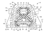
- the first mounting member 16 and the second mounting member 18 are elastically connected to each other by the main rubber elastic body 20. It has a structure.
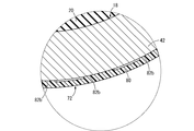
- the inclined surface is provided with a slight inclination angle of several degrees or less in the gradually expanding direction.
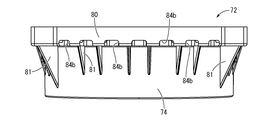
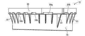
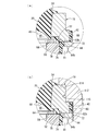
- the pressing member 72 has a substantially cylindrical shape as a whole, and is formed of a hard synthetic resin, metal, or the like.
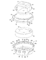
- the seal cylinder portion 74 of the pressing member 72 is substantially the same as or slightly smaller than the axial length of the partition member 58, and an inner flange-like annular contact portion 76 that extends to the inner peripheral side is integrally formed at the lower end opening. Has been.
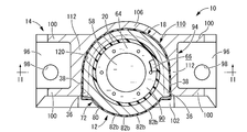
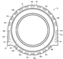
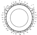
- the transmission preventing hole 84 of the present embodiment is formed at the same position in the circumferential direction as the plurality of press-fit protrusions 82, and is formed in a portion including the axial extension line of the inner peripheral surface of the press-fit protrusion 82. ing. In other words, the outer peripheral end of the transmission preventing hole 84 reaches the inner peripheral end of the press-fit protrusion 82 in a top view. Note that the reinforcing rib 81 provided on the lower surface of the annular plate portion 78 is disposed away from the opening portion of the transmission preventing hole 84 in the annular plate portion 78.
- the positioning means for relatively positioning the second mounting member 18 and the pressing member 72 in the circumferential direction is configured.
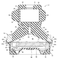
- the pressing member 72 is assembled to the second mounting member 18 by press-fitting the second mounting member 18 into the mounting cylinder portion 80, and thereby the partition member 58 positioned in the accommodated state inside the pressing member 72.
- the flexible film 60 is assembled by being superimposed on the lower side of the second attachment member 18.
- a fluid in which an incompressible fluid is sealed between the large-diameter recess 48 of the main rubber elastic body 20 and the axially opposing surfaces of the flexible membrane 60 in a fluid-tight manner with respect to the external space.
- a chamber 88 is defined.
- the pressure receiving chamber 90 and the equilibrium chamber 92 communicate with each other through an orifice passage 66 formed in the partition member 58, and the orifice passage 66 is based on the relative pressure fluctuation between the pressure receiving chamber 90 and the equilibrium chamber 92.
- the sealed fluid is allowed to flow through.
- the sealing rubber 52 is also sandwiched between the overlapping surfaces of the annular plate portion 78 of the pressing member 72 and the inner peripheral portion of the second mounting member 18 rather than the contact portion 44, thereby improving the sealing performance. You may be allowed to.
- a force in a direction of expanding in the radial direction acts on the mounting cylinder portion 80. Then, the stress accompanying the press-fitting that acts on the mounting cylinder part 80 is transmitted to the seal cylinder part 74 via the annular plate part 78.
- a press-fitting protrusion 82 is formed in the mounting cylinder 80, and the second mounting member 18 is partially press-fitted in the circumferential direction with respect to the mounting cylinder 80 at a portion where the press-fitting protrusion 82 is formed.
- transmission preventing holes 84 are formed at the same circumferential positions as the press-fitting protrusions 82 on the circumference of the annular plate portion 78.
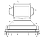
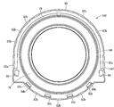
- the outer bracket 14 is attached to the mount body 12 having such a structure, and the mount body 12 is assembled so that the mount body 12 can be inserted from the side into an assembly space formed substantially at the center of the outer bracket 14. It has been.
- the outer bracket 14 is a high-rigidity member formed of iron, aluminum alloy, or the like, and is lightweight and easy to ensure rigidity due to the thickness of the member.
- the die-cast molded product is preferably employed.
- a pressing portion having a substantially arc-shaped peripheral wall inner surface 108 extending in a circumferential direction with a length of a half or more in the circumferential direction and a through hole 104 in the lower portion of the portal portion 94.
- a mount holder portion 110 is formed as an assembly space including the bottom portion 102. The mount holder portion 110 is opened toward the side opposite to the side wall 106, and the opening portion serves as an insertion port into which the mount body 12 is inserted and assembled.
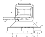
- the engine mount 10 of the present embodiment is brought into the main sealing state by mounting the outer bracket 14 to the second mounting member 18, and thus the second mounting member 18 is attached to the pressing member 72 mounting cylinder.
- the mount main body 12 press-fitted into the portion 80 does not require a high degree of fluid tightness or a large slip resistance. Therefore, the difference between the outer dimension of the second mounting member 18 and the internal dimension of the mounting cylinder portion 80 where the press-fitting protrusion 82 is formed (press-fitting allowance) is set to be relatively small. Stress due to press-fitting that acts on is reduced.
- a crimping engagement portion that engages the second mounting member 18 of the mount body 12 in the insertion direction is formed by crushing and crimping the bottom wall portion of the holding groove 116 of the outer bracket 14.
- the fixing portions 36 and 36 of the second mounting member 18 may be prevented from coming out of the holding grooves 116 and 116 of the outer bracket 14.
- the inner bracket 32 is inserted into the hollow hole 22 of the first mounting member 16 in the assembly in which the mount body 12 is assembled to the outer bracket 14, and the engine mount 10 is configured. Yes.
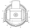
- the layer 31 is compressed and pressed against the top surface of the inner surface of the portal portion 94 in the outer bracket 14.
- the first mounting member 16 is applied to the inner surface 108 of the outer wall 14 of the outer bracket 14 via the both-side cushioning rubber layers 54, 54. Abut.
- an axially perpendicular stopper function that limits the relative displacement of the first mounting member 16 and the second mounting member 18 in the vehicle front-rear or left-right direction can be exhibited.
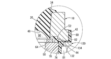
- one corresponding transmission prevention hole 84 is formed for each of the press-fit protrusions 82, and the press-fit protrusions 82 and the transmission prevention holes 84 are arranged at the same position on the circumference. Yes. Therefore, the stress acting on the mounting cylinder 80 at the portion where each press-fitting protrusion 82 is formed is reduced in transmission by the transmission preventing hole 84, and the deformation of the seal cylinder 74 is more advantageously prevented.
- the press-fitting projection 82 is partially formed on the circumference, it is necessary to provide the transmission preventing hole 84 continuously on the entire circumference of the annular plate portion 78. In addition, it is possible to satisfactorily ensure the strength of the annular plate 78 and the pressing member 72.
- the press-fit protrusion 82 extends in a certain length in the circumferential direction and the axial direction, respectively, and the protruding tip of the press-fit protrusion 82 is a surface that extends in the circumferential direction and the axial direction. Therefore, the press-fitting surfaces of the second mounting member 18 and the mounting cylinder part 80 can be secured with a sufficient area, and the resistance against the seal reaction force exerted by the press-fitting, in other words, the drag resistance against the removal can be effectively obtained. be able to.
- the transmission preventing hole 84 is formed at the outer peripheral end portion of the annular plate portion 78 including the extension line in the axial direction of the inner peripheral surface of the mounting cylinder portion 80 (the protruding tip end surface of the press-fit protrusion 82).
- the reinforcing action by the press-fitting protrusion 82 is advantageously avoided, and the stress transmission from the mounting cylinder 80 to the annular plate 78 is effectively reduced.
- the target drag is exerted in at least a part in the press-fit state. Just do it. That is, a structure in which the press-fitting protrusion 82 and the press-fitting part 42 are in partial contact with each other in the axial direction, and a gap is formed between the press-fitting protrusion 82 and the press-fitting part 42 in the radial direction in the other parts. Is possible.
- the inner peripheral surface of the press-fitting protrusion 82 and the outer peripheral surface of the press-fit portion 42 of the second mounting member 18 may be inclined surfaces that are parallel to each other and are inclined with respect to the axial direction.
- the inner peripheral surface of the press-fitting protrusion 82 is an inclined surface that expands toward the upper opening of the mounting cylinder 80, the second mounting member 18 can be easily inserted into the mounting cylinder 80.
- the transmission preventing portion of the present embodiment is a transmission preventing hole 84 and the inner peripheral surface is sufficiently separated in the radial direction, the inner peripheral surface is in contact with or close to the radial direction in the slit ( As compared with the notch), the transmission of stress is effectively reduced even when the annular plate portion 78 is deformed.
- the transmission preventing hole 84 is easier to form when the annular plate portion 78 is molded than a slit or the like, and post-processing for forming the transmission preventing portion is not necessary.
- the transmission preventing portion is formed in the portion where the stress due to press-fitting is transmitted, it is not always necessary to be disposed at the same circumferential position as the press-fitting protrusion.
- the transmission preventing part and the press-fitting protrusion can be arranged at different positions in the circumferential direction.
- the specific structure of the inner bracket and the outer bracket is not limited at all.
- a structure that does not have the top of the portal portion may be adopted.
- a rebound stopper function is required, a rebound stopper having another structure may be separately employed.
- the first mounting member can adopt a structure such as a block shape as appropriate.
Abstract
Description
Claims (13)
- 第一の取付部材と環状の第二の取付部材が本体ゴム弾性体で弾性連結されていると共に、壁部の一部が該本体ゴム弾性体で構成されて非圧縮性流体を封入された流体室を有する流体封入式防振装置において、
前記第二の取付部材には筒状の封止用部材が取り付けられて、該封止用部材が段差部の両側に取付筒部とシール筒部の各一方を備えていると共に、該取付筒部の内周面と該第二の取付部材の外周面との少なくとも一方に圧入突部が周上で部分的に形成されて、該第二の取付部材が該取付筒部に差し入れられて該圧入突部の形成部分で圧入固定されている一方、
該封止用部材の該段差部には該取付筒部から該シール筒部への圧入に伴う応力の伝達部分に応力伝達を低減する伝達防止部が設けられていることを特徴とする流体封入式防振装置。 - 複数の前記圧入突部が前記第二の取付部材および前記取付筒部の周上で形成されている請求項1に記載の流体封入式防振装置。
- 前記圧入突部が前記封止用部材における前記取付筒部の内周面に突出して形成されている請求項1又は2に記載の流体封入式防振装置。
- 前記第二の取付部材および前記取付筒部における前記圧入突部の突出先端と該圧入突部の突出先端の当接面とが、何れも軸方向に非傾斜で延びている請求項1~3の何れか一項に記載の流体封入式防振装置。
- 前記圧入突部が周方向に所定長さで連続して延びており、該圧入突部の突出先端が周方向に広がっている請求項1~4の何れか一項に記載の流体封入式防振装置。
- 前記圧入突部が前記取付筒部の基端まで軸方向に延びている請求項1~5の何れか一項に記載の流体封入式防振装置。
- 前記伝達防止部の周方向長さが前記圧入突部の周方向長さ以上とされており、該圧入突部が該伝達防止部の周方向中間に配置されている請求項1~6の何れか一項に記載の流体封入式防振装置。
- 前記伝達防止部が前記段差部を貫通する伝達防止孔とされている請求項1~7の何れか一項に記載の流体封入式防振装置。
- 前記伝達防止部が前記段差部における前記取付筒部の内周面の延長線を含む部位に設けられている請求項1~8の何れか一項に記載の流体封入式防振装置。
- 前記段差部の変形剛性を高める補強リブが、該段差部における前記伝達防止部を外れた部位に設けられている請求項1~9の何れか一項に記載の流体封入式防振装置。
- 前記第二の取付部材が前記封止用部材の前記取付筒部に圧入されてシールゴムが圧縮されることにより前記流体室が仮封止されると共に、
該第二の取付部材に連結部材が装着されて、該第二の取付部材と該封止用部材の間に圧入方向への押圧力が該連結部材によって及ぼされて該シールゴムの圧縮率が高められることにより該流体室が本封止されている請求項1~10の何れか一項に記載の流体封入式防振装置。 - 前記流体室が壁部の一部を前記本体ゴム弾性体で構成された受圧室と壁部の一部を可撓性膜で構成された平衡室とを含んで構成されており、それら受圧室と平衡室が前記第二の取付部材によって支持される仕切部材を挟んだ軸方向両側に配されていると共に、該仕切部材が前記封止用部材における前記シール筒部の内周側に配設されて、該仕切部材の外周面が該シール筒部の内周面に重ね合わされている一方、
該第二の取付部材と該仕切部材の間にシールゴムが配されており、該第二の取付部材の前記取付筒部への圧入によって該シールゴムが該第二の取付部材と該仕切部材の間で圧縮されて流体密に封止されている請求項1~11の何れか一項に記載の流体封入式防振装置。 - 前記第二の取付部材と前記封止用部材の前記取付筒部とを周方向で相互に位置決めする位置決め手段が設けられている請求項1~12の何れか一項に記載の流体封入式防振装置。
Priority Applications (5)
| Application Number | Priority Date | Filing Date | Title |
|---|---|---|---|
| MX2016008469A MX2016008469A (es) | 2014-12-08 | 2015-08-31 | Dispositivo de amortiguacion de vibraciones llenado con fluido. |
| CN201580045565.4A CN108603560B (zh) | 2014-12-08 | 2015-08-31 | 流体封入式防振装置 |
| BR112016015385-5A BR112016015385B1 (pt) | 2014-12-08 | 2015-08-31 | Dispositivo de amortecimento por vibração preenchido por fluido |
| DE112015000875.6T DE112015000875B4 (de) | 2014-12-08 | 2015-08-31 | Fluidgefüllte Schwingungsdämpfungsvorrichtung |
| US15/135,621 US10415665B2 (en) | 2014-12-08 | 2016-04-22 | Fluid-filled vibration-damping device |
Applications Claiming Priority (2)
| Application Number | Priority Date | Filing Date | Title |
|---|---|---|---|
| JP2014-247734 | 2014-12-08 | ||
| JP2014247734A JP5941966B2 (ja) | 2014-12-08 | 2014-12-08 | 流体封入式防振装置 |
Related Child Applications (1)
| Application Number | Title | Priority Date | Filing Date |
|---|---|---|---|
| US15/135,621 Continuation US10415665B2 (en) | 2014-12-08 | 2016-04-22 | Fluid-filled vibration-damping device |
Publications (1)
| Publication Number | Publication Date |
|---|---|
| WO2016092917A1 true WO2016092917A1 (ja) | 2016-06-16 |
Family
ID=56107114
Family Applications (1)
| Application Number | Title | Priority Date | Filing Date |
|---|---|---|---|
| PCT/JP2015/074646 WO2016092917A1 (ja) | 2014-12-08 | 2015-08-31 | 流体封入式防振装置 |
Country Status (7)
| Country | Link |
|---|---|
| US (1) | US10415665B2 (ja) |
| JP (1) | JP5941966B2 (ja) |
| CN (1) | CN108603560B (ja) |
| BR (1) | BR112016015385B1 (ja) |
| DE (1) | DE112015000875B4 (ja) |
| MX (1) | MX2016008469A (ja) |
| WO (1) | WO2016092917A1 (ja) |
Cited By (1)
| Publication number | Priority date | Publication date | Assignee | Title |
|---|---|---|---|---|
| WO2018047431A1 (ja) * | 2016-09-08 | 2018-03-15 | 株式会社ブリヂストン | 防振装置本体および防振装置 |
Families Citing this family (18)
| Publication number | Priority date | Publication date | Assignee | Title |
|---|---|---|---|---|
| JP6190651B2 (ja) * | 2013-07-23 | 2017-08-30 | 住友理工株式会社 | 防振装置 |
| JP6469497B2 (ja) * | 2015-03-31 | 2019-02-13 | 株式会社ブリヂストン | 防振装置 |
| JP6546511B2 (ja) * | 2015-10-30 | 2019-07-17 | 住友理工株式会社 | ブラケット付き防振装置 |
| US9931923B2 (en) * | 2016-05-31 | 2018-04-03 | Sumitomo Riko Company Limited | Bracket-equipped vibration-damping device |
| JP6813998B2 (ja) * | 2016-09-06 | 2021-01-13 | 山下ゴム株式会社 | 防振装置 |
| KR102479485B1 (ko) | 2016-12-13 | 2022-12-19 | 현대자동차주식회사 | 분산된 스토퍼들을 가지는 자동차의 트랜스미션 마운트 |
| JP6808554B2 (ja) * | 2017-03-24 | 2021-01-06 | 株式会社ブリヂストン | 防振装置 |
| DE102017215768B4 (de) * | 2017-09-07 | 2020-10-22 | Contitech Vibration Control Gmbh | Lager, vorzugsweise Motorlager oder Getriebelager |
| JP6902456B2 (ja) * | 2017-11-21 | 2021-07-14 | 住友理工株式会社 | ブラケット付防振装置 |
| JP7000243B2 (ja) * | 2018-04-26 | 2022-01-19 | 山下ゴム株式会社 | 防振装置 |
| US10988015B2 (en) * | 2018-12-06 | 2021-04-27 | GM Global Technology Operations LLC | Multi-position mount system |
| JP7146681B2 (ja) * | 2019-03-26 | 2022-10-04 | 住友理工株式会社 | ブラケット付き防振装置 |
| JP7217186B2 (ja) * | 2019-03-26 | 2023-02-02 | 住友理工株式会社 | ブラケット付き防振装置 |
| US11927234B2 (en) * | 2019-06-11 | 2024-03-12 | Yamashita Rubber Co., Ltd. | Vibration proofing device and bracket |
| CN113728177B (zh) * | 2019-06-11 | 2023-05-02 | 山下橡胶株式会社 | 防振装置 |
| KR20210153256A (ko) * | 2020-06-10 | 2021-12-17 | 현대자동차주식회사 | 자동차용 트랜스미션 마운트 |
| FR3119654B1 (fr) * | 2021-02-09 | 2023-05-26 | Hutchinson | Support antivibratoire et véhicule comportant un tel support antivibratoire. |
| JP2022146626A (ja) * | 2021-03-22 | 2022-10-05 | 住友理工株式会社 | ブラケット付き防振装置とその製造方法 |
Citations (4)
| Publication number | Priority date | Publication date | Assignee | Title |
|---|---|---|---|---|
| JPS5837337A (ja) * | 1981-08-31 | 1983-03-04 | Toyoda Gosei Co Ltd | 液封入防振装置の組付構造 |
| EP2381127A1 (en) * | 2010-04-20 | 2011-10-26 | Trelleborg Automotive Germany GmbH | Hydraulically damped bearing for mounting an engine |
| WO2012085766A1 (en) * | 2010-12-24 | 2012-06-28 | Teklas Kaucuk Sanayi Ve Ticaret A.S. | A hydraulic mount |
| JP2013117258A (ja) * | 2011-12-02 | 2013-06-13 | Bridgestone Corp | 防振装置 |
Family Cites Families (8)
| Publication number | Priority date | Publication date | Assignee | Title |
|---|---|---|---|---|
| FR2578609B1 (fr) * | 1985-03-11 | 1989-04-28 | Hutchinson | Dispositif de suspension hydroelastique pour plates-formes mobiles de forage auto-elevatrices |
| JP2785949B2 (ja) * | 1989-02-15 | 1998-08-13 | 株式会社ブリヂストン | 防振装置 |
| JPH08170683A (ja) * | 1994-12-19 | 1996-07-02 | Tokai Rubber Ind Ltd | 液体封入式防振マウント |
| CN2308763Y (zh) | 1997-10-10 | 1999-02-24 | 吉林工业大学 | 发动机液压阻尼式悬置元件 |
| JP4058685B2 (ja) * | 2003-03-26 | 2008-03-12 | 東海ゴム工業株式会社 | 流体封入式防振装置 |
| DE102004039825B4 (de) * | 2004-08-16 | 2010-10-14 | Carl Freudenberg Kg | Hydraulisch dämpfendes Lager |
| JP5198784B2 (ja) * | 2007-03-29 | 2013-05-15 | ボッシュ株式会社 | コイルスプリングの防振機構およびこれを用いた倍力装置 |
| DE102011006156B4 (de) * | 2011-03-25 | 2013-02-21 | Trelleborg Automotive Germany Gmbh | Hydraulisch dämpfendes Lager |
-
2014
- 2014-12-08 JP JP2014247734A patent/JP5941966B2/ja active Active
-
2015
- 2015-08-31 DE DE112015000875.6T patent/DE112015000875B4/de active Active
- 2015-08-31 WO PCT/JP2015/074646 patent/WO2016092917A1/ja active Application Filing
- 2015-08-31 BR BR112016015385-5A patent/BR112016015385B1/pt active IP Right Grant
- 2015-08-31 CN CN201580045565.4A patent/CN108603560B/zh active Active
- 2015-08-31 MX MX2016008469A patent/MX2016008469A/es unknown
-
2016
- 2016-04-22 US US15/135,621 patent/US10415665B2/en active Active
Patent Citations (4)
| Publication number | Priority date | Publication date | Assignee | Title |
|---|---|---|---|---|
| JPS5837337A (ja) * | 1981-08-31 | 1983-03-04 | Toyoda Gosei Co Ltd | 液封入防振装置の組付構造 |
| EP2381127A1 (en) * | 2010-04-20 | 2011-10-26 | Trelleborg Automotive Germany GmbH | Hydraulically damped bearing for mounting an engine |
| WO2012085766A1 (en) * | 2010-12-24 | 2012-06-28 | Teklas Kaucuk Sanayi Ve Ticaret A.S. | A hydraulic mount |
| JP2013117258A (ja) * | 2011-12-02 | 2013-06-13 | Bridgestone Corp | 防振装置 |
Cited By (3)
| Publication number | Priority date | Publication date | Assignee | Title |
|---|---|---|---|---|
| WO2018047431A1 (ja) * | 2016-09-08 | 2018-03-15 | 株式会社ブリヂストン | 防振装置本体および防振装置 |
| JP2018040451A (ja) * | 2016-09-08 | 2018-03-15 | 株式会社ブリヂストン | 防振装置本体および防振装置 |
| US11654764B2 (en) | 2016-09-08 | 2023-05-23 | Prospira Corporation | Vibration-damping device body and vibration-damping device |
Also Published As
| Publication number | Publication date |
|---|---|
| CN108603560A (zh) | 2018-09-28 |
| MX2016008469A (es) | 2016-10-19 |
| CN108603560B (zh) | 2020-01-24 |
| JP5941966B2 (ja) | 2016-06-29 |
| US20160238102A1 (en) | 2016-08-18 |
| DE112015000875T8 (de) | 2017-01-12 |
| BR112016015385A2 (ja) | 2017-08-08 |
| US10415665B2 (en) | 2019-09-17 |
| DE112015000875B4 (de) | 2018-01-04 |
| JP2016109216A (ja) | 2016-06-20 |
| DE112015000875T5 (de) | 2016-11-10 |
| BR112016015385B1 (pt) | 2023-03-21 |
Similar Documents
| Publication | Publication Date | Title |
|---|---|---|
| JP5941966B2 (ja) | 流体封入式防振装置 | |
| JP5753331B1 (ja) | 流体封入式防振装置 | |
| JP5753225B2 (ja) | 防振装置 | |
| JP6275493B2 (ja) | ブラケット付防振装置 | |
| US10436280B2 (en) | Fluid-filled vibration damping device | |
| EP2706257B1 (en) | Axially damped hydraulic mount assembly | |
| WO2015145672A1 (ja) | 防振装置 | |
| JP5907783B2 (ja) | 流体封入式防振装置 | |
| JP2009074653A (ja) | 防振装置とその製造方法 | |
| JP2017082991A (ja) | ブラケット付き防振装置 | |
| JP5449052B2 (ja) | 防振装置 | |
| JP2015068356A (ja) | 流体封入式筒形防振装置 | |
| JP4241478B2 (ja) | 流体封入式の防振連結ロッド | |
| CN109715976B (zh) | 流体封入式防振装置 | |
| JP4937222B2 (ja) | 流体封入式防振連結ロッド | |
| JP4081421B2 (ja) | 防振マウント組立体 | |
| JP6231761B2 (ja) | 液封入式防振装置 | |
| JP6722570B2 (ja) | 流体封入式筒形防振装置 | |
| JP2005291447A (ja) | 流体封入式の防振連結ロッド | |
| JP2010032023A (ja) | 流体封入式防振装置 | |
| JP2003184943A (ja) | 流体封入式防振装置 | |
| JP5119195B2 (ja) | 流体封入式防振装置 | |
| JP4277314B2 (ja) | 流体封入式筒型防振装置およびその製造方法 | |
| JP2006002857A (ja) | 流体封入式筒形防振装置 | |
| JP3658843B2 (ja) | 流体封入式筒型マウント装置 |
Legal Events
| Date | Code | Title | Description |
|---|---|---|---|
| WWE | Wipo information: entry into national phase |
Ref document number: MX/A/2016/008469 Country of ref document: MX |
|
| REG | Reference to national code |
Ref country code: BR Ref legal event code: B01A Ref document number: 112016015385 Country of ref document: BR |
|
| 121 | Ep: the epo has been informed by wipo that ep was designated in this application |
Ref document number: 15867209 Country of ref document: EP Kind code of ref document: A1 |
|
| WWE | Wipo information: entry into national phase |
Ref document number: 112015000875 Country of ref document: DE |
|
| ENP | Entry into the national phase |
Ref document number: 112016015385 Country of ref document: BR Kind code of ref document: A2 Effective date: 20160630 |
|
| 122 | Ep: pct application non-entry in european phase |
Ref document number: 15867209 Country of ref document: EP Kind code of ref document: A1 |