以下、本発明の実施形態について、図面を参照しつつ説明する。
Hereinafter, embodiments of the present invention will be described with reference to the drawings.
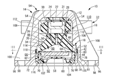
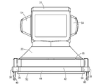
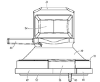
図1~3には、本発明に従う構造とされた流体封入式防振装置の第一の実施形態として、自動車用のエンジンマウント10が示されている。このエンジンマウント10は、図4~9に示されている防振装置本体としてのマウント本体12に対して、連結部材としてのアウタブラケット14が装着された構造を有している。なお、以下の説明において、上下方向とは、原則としてマウント軸方向である図2中の上下方向を言う。また、マウント本体12を示す図5~8と、後述する本体ゴム弾性体20の一体加硫成形品を示す図10~13と、後述する押圧部材72を示す図14~17は、何れも見易さのために図2,3に対して拡大して示されている。
FIGS. 1 to 3 show an engine mount 10 for an automobile as a first embodiment of a fluid-filled vibration isolator constructed according to the present invention. The engine mount 10 has a structure in which an outer bracket 14 as a connecting member is attached to a mount body 12 as a vibration isolator body shown in FIGS. In the following description, the vertical direction means the vertical direction in FIG. 2 which is the mount axis direction in principle. 5 to 8 showing the mount main body 12, FIGS. 10 to 13 showing an integrally vulcanized molded product of the main rubber elastic body 20 described later, and FIGS. 14 to 17 showing the pressing member 72 described later are all seen. For ease of illustration, it is shown enlarged relative to FIGS.
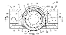
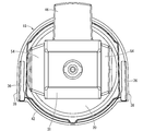
より詳細には、マウント本体12は、図4~9に示されているように、第一の取付部材16と第二の取付部材18とが、本体ゴム弾性体20で相互に弾性連結された構造を有している。
More specifically, in the mount body 12, as shown in FIGS. 4 to 9, the first mounting member 16 and the second mounting member 18 are elastically connected to each other by the main rubber elastic body 20. It has a structure.
第一の取付部材16は、ストレートに延びる中空孔22を備えた略矩形の筒形状を有する嵌着部24と、嵌着部24の周上の一辺から下方に突出する逆向きの略円錐台殻形状を有する固着部26とを、一体で備えており、鉄やアルミニウム合金、硬質の合成樹脂等で形成された高剛性の部材が用いられている。そして、第一の取付部材16は、嵌着部24の中心軸がマウント軸方向に対して略直交する方向に延びるように配されている。また、嵌着部24の内周面には、嵌着ゴム層28が全周を覆うように被着形成されている一方、嵌着部24の外周面には、被覆ゴム層30が全周を覆うように被着形成されている。更に、嵌着部24の上壁部分には、マウント軸方向の上方に向かって突出する上部緩衝ゴム層31が、被覆ゴム層30と一体的に形成されている。
The first mounting member 16 includes a fitting portion 24 having a substantially rectangular tube shape with a hollow hole 22 extending straight, and a reverse substantially truncated cone protruding downward from one side on the circumference of the fitting portion 24. The fixing portion 26 having a shell shape is integrally provided, and a highly rigid member formed of iron, aluminum alloy, hard synthetic resin, or the like is used. The first mounting member 16 is arranged so that the center axis of the fitting portion 24 extends in a direction substantially orthogonal to the mount axis direction. In addition, the fitting rubber layer 28 is formed on the inner peripheral surface of the fitting portion 24 so as to cover the entire circumference, while the covering rubber layer 30 is formed on the outer circumferential surface of the fitting portion 24. Is formed so as to cover. Further, an upper buffer rubber layer 31 protruding upward in the mount axis direction is formed integrally with the covering rubber layer 30 on the upper wall portion of the fitting portion 24.
そして、かかる第一の取付部材16には、図2に示されているように、インナブラケット32が嵌着部24に側方から圧入状態で組み付けられて嵌着固定されるようになっており、かかるインナブラケット32を介して、第一の取付部材16がパワーユニットに取り付けられるようになっている。即ち、インナブラケット32の基端部分には、パワーユニット側への固定用ボルトの挿通孔が複数形成されている一方、インナブラケット32の先端部分は、略H形断面形状とされており、第一の取付部材16の中空孔22に対応した外周寸法をもって直線的に延びている。
Then, as shown in FIG. 2, the inner bracket 32 is assembled to the first mounting member 16 in a press-fitted state from the side and fixedly fitted. The first attachment member 16 is attached to the power unit via the inner bracket 32. That is, a plurality of insertion holes for fixing bolts to the power unit side are formed in the proximal end portion of the inner bracket 32, while the distal end portion of the inner bracket 32 has a substantially H-shaped cross section. The mounting member 16 extends linearly with an outer peripheral dimension corresponding to the hollow hole 22.
また、第二の取付部材18は金属製の高剛性部材とされており、中央部分をマウント軸方向に貫通する大径の透孔34が設けられた厚肉の略円環形状とされている。なお、第二の取付部材18の内周面は、上方に向かって拡径するテーパ状の傾斜面とされている。
The second mounting member 18 is a metal high-rigidity member, and has a thick, substantially annular shape provided with a large-diameter through hole 34 penetrating the center portion in the mount axis direction. . The inner peripheral surface of the second mounting member 18 is a tapered inclined surface whose diameter increases upward.
さらに、第二の取付部材18には、外周面上に突出して一対の固定部36,36が一体形成されている。これら一対の固定部36,36は、それぞれ第二の取付部材18の外周面上で軸直角方向に広がる厚肉の略ブロック状とされており、第二の取付部材18の外周部分において軸直角方向で対向位置する部位に設けられている。そして、これら一対の固定部36,36のそれぞれは、第二の取付部材18の径方向一方向で対向位置する一対の外周部位からそれぞれ接線方向で略平行に延び出した外周面38,38を有している。また、一対の固定部36,36には、下方に向かって突出する挿通ピン40がそれぞれ形成されている。なお、本実施形態では、かかる一対の固定部36,36における外周面38,38が、第二の取付部材18の径方向一方向での対向部位から接線方向に向かって延び出すに従って、相互に次第に拡開する方向に数度以下の僅かな傾斜角が付された傾斜面とされている。
Furthermore, the second mounting member 18 is integrally formed with a pair of fixing portions 36 and 36 so as to protrude on the outer peripheral surface. Each of the pair of fixing portions 36 and 36 has a thick, substantially block shape extending in the direction perpendicular to the axis on the outer peripheral surface of the second mounting member 18. It is provided in the site | part which opposes in a direction. And each of these pair of fixing | fixed parts 36 and 36 has the outer peripheral surfaces 38 and 38 extended substantially parallel in the tangential direction, respectively from a pair of outer peripheral part which opposes the radial direction of the 2nd attachment member 18. Have. The pair of fixing portions 36 are formed with insertion pins 40 protruding downward. In the present embodiment, as the outer peripheral surfaces 38 of the pair of fixing portions 36 and 36 extend in the tangential direction from the opposing portions in the radial direction of the second mounting member 18, The inclined surface is provided with a slight inclination angle of several degrees or less in the gradually expanding direction.
また、第二の取付部材18の下部には、外周に向かって突出する圧入部42が全周に亘って連続して形成されている。かかる圧入部42が形成されることにより、第二の取付部材18の外周面が段付き円筒形状を呈しており、第二の取付部材18の下部が上部よりも外径寸法を大きくされている。更に、第二の取付部材18の外周部分には、下方に突出する環状の当接部44が一体形成されており、内周部分の下面が外周部分よりも上方に位置している。なお、圧入部42の外周面は、軸方向に実質的に非傾斜で直線的に延びている。ここで言う実質的に非傾斜は、第二の取付部材18の成形時に金型の取外しを容易にするための抜きテーパ程度であれば許容するものである。
Further, a press-fit portion 42 that protrudes toward the outer periphery is continuously formed at the lower portion of the second mounting member 18 over the entire periphery. By forming the press-fit portion 42, the outer peripheral surface of the second mounting member 18 has a stepped cylindrical shape, and the lower diameter of the lower portion of the second mounting member 18 is larger than the upper portion. . Further, an annular contact portion 44 protruding downward is integrally formed on the outer peripheral portion of the second mounting member 18, and the lower surface of the inner peripheral portion is positioned above the outer peripheral portion. Note that the outer peripheral surface of the press-fit portion 42 extends substantially linearly in a non-inclined direction in the axial direction. The substantially non-inclination mentioned here is allowed as long as it is about a taper taper for facilitating the removal of the mold when the second mounting member 18 is molded.
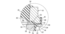
そして、第二の取付部材18の中心軸上で上方に所定距離を隔てて、第一の取付部材16が配置されており、これら第一の取付部材16と第二の取付部材18が、本体ゴム弾性体20によって相互に弾性連結されている。本体ゴム弾性体20は、厚肉大径の略円錐台形状とされており、小径側の端部に第一の取付部材16が加硫接着されていると共に、大径側の端部の外周面に第二の取付部材18の内周面が加硫接着されている。
And the 1st attachment member 16 is arrange | positioned on the center axis | shaft of the 2nd attachment member 18 at predetermined intervals, and these 1st attachment members 16 and the 2nd attachment member 18 are main bodies. The rubber elastic bodies 20 are elastically connected to each other. The main rubber elastic body 20 has a thick, large-diameter, generally frustoconical shape. The first mounting member 16 is vulcanized and bonded to the end portion on the small-diameter side, and the outer periphery of the end portion on the large-diameter side. The inner peripheral surface of the second mounting member 18 is vulcanized and bonded to the surface.
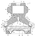
なお、本体ゴム弾性体20には、第一の取付部材16の内外周面に被着された嵌着ゴム層28と被覆ゴム層30および上部緩衝ゴム層31が、一体的に形成されている。そして、本体ゴム弾性体20は、図10~13に示すような第一の取付部材16と第二の取付部材18を備えた一体加硫成形品として形成されている。
The main rubber elastic body 20 is integrally formed with a fitting rubber layer 28, a covering rubber layer 30 and an upper cushioning rubber layer 31 that are attached to the inner and outer peripheral surfaces of the first mounting member 16. . The main rubber elastic body 20 is formed as an integrally vulcanized molded product having a first mounting member 16 and a second mounting member 18 as shown in FIGS.
また、本体ゴム弾性体20には、図11,12に示すように、小径側端部付近において、第一の取付部材16の嵌着部24の一方の開口縁部における下壁部分から軸方向外方に向かって所定厚さの舌片状または平板状に延び出す下部緩衝ゴム層46が一体的に形成されている。更にまた、本体ゴム弾性体20には、大径凹所48が形成されている。大径凹所48は、逆向きの略すり鉢形状を呈する凹所であって、本体ゴム弾性体20の大径側の端面に開口している。また、本体ゴム弾性体20には、内外に貫通して延びる注入用孔50が設けられている。この注入用孔50は、本体ゴム弾性体20の弾性主軸上を一定の円形断面で直線的に延びており、大径凹所48の上底部の中央に設けられた内側開口部から、第一の取付部材16を貫通して中空孔22内に設けられた外側開口部にまで延びている。
Further, as shown in FIGS. 11 and 12, the main rubber elastic body 20 has an axial direction from the lower wall portion at one opening edge portion of the fitting portion 24 of the first mounting member 16 in the vicinity of the end portion on the small diameter side. A lower cushioning rubber layer 46 that extends outward in a tongue-like shape or a flat plate shape with a predetermined thickness is integrally formed. Furthermore, a large-diameter recess 48 is formed in the main rubber elastic body 20. The large-diameter recess 48 is a recess exhibiting a substantially mortar shape in the reverse direction, and is open to the end surface on the large-diameter side of the main rubber elastic body 20. Further, the main rubber elastic body 20 is provided with an injection hole 50 extending through the inside and outside. The injection hole 50 extends linearly on the elastic main axis of the main rubber elastic body 20 with a constant circular cross section, and from the inner opening provided at the center of the upper bottom of the large-diameter recess 48, And extending to the outer opening provided in the hollow hole 22.
さらに、本体ゴム弾性体20の大径凹所48の外周側には、図13に示すように、シール部材としてのシールゴム52が形成されている。シールゴム52は、第二の取付部材18の下面を覆うように固着された薄肉のゴム層であって、本実施形態では本体ゴム弾性体20と一体形成されており、第二の取付部材18の下面において当接部44の内周側の略全面を覆っている。
Further, a seal rubber 52 as a seal member is formed on the outer peripheral side of the large-diameter recess 48 of the main rubber elastic body 20 as shown in FIG. The seal rubber 52 is a thin rubber layer fixed so as to cover the lower surface of the second mounting member 18, and is integrally formed with the main rubber elastic body 20 in the present embodiment. The lower surface covers substantially the entire inner peripheral side of the contact portion 44.
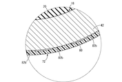
更にまた、本体ゴム弾性体20の被覆ゴム層30には、第一の取付部材16の外方に突出する一対の側方緩衝ゴム層54,54が形成されている。これらの側方緩衝ゴム層54,54は、第一の取付部材16の中空孔22の延出方向(図11中の左右方向)に直交する方向(図10中の左右方向)に、それぞれ反対向きに突出している。かかる側方緩衝ゴム層54,54は略台形の断面を有する山型とされており、図1に示されているように、エンジンマウント10の単体状態では、側方緩衝ゴム層54,54の突出先端面と後述するマウントホルダ部110の周壁内面108との対向面間に所定距離の隙間が形成されている。
Furthermore, the covering rubber layer 30 of the main rubber elastic body 20 is formed with a pair of side buffer rubber layers 54, 54 protruding outward from the first mounting member 16. These side cushioning rubber layers 54 and 54 are opposite to the direction (left-right direction in FIG. 10) orthogonal to the extending direction (left-right direction in FIG. 11) of the hollow hole 22 of the first mounting member 16, respectively. It protrudes in the direction. The side shock absorbing rubber layers 54 and 54 are mountain-shaped having a substantially trapezoidal cross section. As shown in FIG. 1, when the engine mount 10 is in a single state, the side shock absorbing rubber layers 54 and 54 are formed. A gap of a predetermined distance is formed between opposing surfaces of the protruding front end surface and a peripheral wall inner surface 108 of the mount holder portion 110 described later.
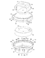
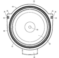
また、本体ゴム弾性体20の一体加硫成形品を構成する第二の取付部材18には、その下側に仕切部材58と可撓性膜60が、重ね合わされて配設されている。換言すれば、第二の取付部材18におけるマウント中心軸方向で、本体ゴム弾性体20が配設される側と反対の側に仕切部材58と可撓性膜60が、重ね合わされて配設されている。
Further, a partition member 58 and a flexible film 60 are disposed on the second attachment member 18 constituting the integrally vulcanized molded product of the main rubber elastic body 20 so as to overlap each other. In other words, the partition member 58 and the flexible film 60 are disposed to overlap each other on the side opposite to the side on which the main rubber elastic body 20 is disposed in the mount center axis direction of the second mounting member 18. ing.
仕切部材58は、全体として厚肉の略大径円板形状とされており、金属や硬質の合成樹脂等で形成されている。また、仕切部材58には、外周部分を周方向の略一周弱の長さで延びる周溝62が上面に開口して形成されている。そして、仕切部材58の上面に薄肉の円板形状の蓋板64が重ね合わされて、周溝62の開口が覆蓋されることにより、周方向に延びるオリフィス通路66が形成されている。なお、このオリフィス通路66の周方向一方の端部は、仕切部材58を貫通して下方に開口せしめられていると共に、周方向他方の端部は、蓋板64を貫通して上方に開口せしめられている。
The partition member 58 has a thick, substantially large-diameter disk shape as a whole, and is formed of metal, hard synthetic resin, or the like. In addition, the partition member 58 is formed with a circumferential groove 62 having an outer peripheral portion extending substantially less than one circumference in the circumferential direction so as to open on the upper surface. A thin disc-shaped cover plate 64 is superimposed on the upper surface of the partition member 58, and the opening of the circumferential groove 62 is covered, thereby forming an orifice passage 66 extending in the circumferential direction. One end in the circumferential direction of the orifice passage 66 passes through the partition member 58 and opens downward, and the other end in the circumferential direction passes through the cover plate 64 and opens upward. It has been.
一方、可撓性膜60は、全体として薄肉の略円板形状を有するゴム弾性膜や変形容易な樹脂膜等によって構成されており、径方向の中間部分に所定の弛みが設けられることで変形が容易に許容されるようになっている。また、可撓性膜60の外周縁部には、厚肉とされた環状シール部68が一体的に形成されている。そして、仕切部材58の外周部分の下面に対して環状シール部68が密着状態で重ね合わされることによって、可撓性膜60が、仕切部材58の下面を全体に亘って覆うようにして配設されている。なお、仕切部材58の外周部分には、下面に開口して周方向に延びる環状の位置決め溝70が形成されており、この位置決め溝70に環状シール部68の上端が入り込むようにしてセットされている。
On the other hand, the flexible film 60 is composed of a rubber elastic film having a thin and substantially disk shape as a whole, an easily deformable resin film, and the like, and is deformed by providing a predetermined slack in the intermediate portion in the radial direction. Is easily tolerated. A thick annular seal 68 is integrally formed on the outer peripheral edge of the flexible membrane 60. Then, the annular seal portion 68 is overlapped in close contact with the lower surface of the outer peripheral portion of the partition member 58 so that the flexible film 60 covers the entire lower surface of the partition member 58. Has been. An annular positioning groove 70 is formed in the outer peripheral portion of the partition member 58 so as to open on the lower surface and extend in the circumferential direction. The positioning groove 70 is set so that the upper end of the annular seal portion 68 enters. Yes.
そして、このように互いに重ね合わされた仕切部材58と可撓性膜60には、更にそれらの外周面を覆うようにして封止用部材としての押圧部材72が組み付けられている。
Further, the partition member 58 and the flexible film 60 that are overlapped with each other in this manner are assembled with a pressing member 72 as a sealing member so as to cover the outer peripheral surface thereof.
かかる押圧部材72は、図14~17に示すように、全体として略円筒形状を有しており、硬質の合成樹脂や金属等によって形成されている。押圧部材72のシール筒部74は、仕切部材58の軸方向長さと略同じか僅かに小さくされており、下端開口部には内周側に広がる内フランジ状の環状当接部76が一体形成されている。
As shown in FIGS. 14 to 17, the pressing member 72 has a substantially cylindrical shape as a whole, and is formed of a hard synthetic resin, metal, or the like. The seal cylinder portion 74 of the pressing member 72 is substantially the same as or slightly smaller than the axial length of the partition member 58, and an inner flange-like annular contact portion 76 that extends to the inner peripheral side is integrally formed at the lower end opening. Has been.
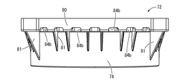
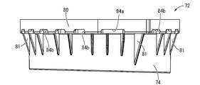
また、押圧部材72のシール筒部74の上端開口部には、外周側に広がる外フランジ状の段差部としての環状板部78が形成されている。更にまた、かかる環状板部78の外周縁部には、上方に向かって突出する取付筒部80が全周に連続して形成されている。また、押圧部材72におけるシール筒部74の外周面には、補強リブ81が突出形成されている。補強リブ81は、下方に行くに従って径方向寸法が小さくなる略三角板状であって、シール筒部74の外周面と環状板部78の下面とに一体で繋がって形成されている。
In addition, an annular plate portion 78 as an outer flange-shaped stepped portion that extends to the outer peripheral side is formed at the upper end opening of the seal cylinder portion 74 of the pressing member 72. Furthermore, an attachment cylinder portion 80 protruding upward is formed on the outer peripheral edge portion of the annular plate portion 78 continuously on the entire circumference. Further, a reinforcing rib 81 protrudes from the outer peripheral surface of the seal cylinder portion 74 in the pressing member 72. The reinforcing rib 81 has a substantially triangular plate shape whose radial dimension decreases as it goes downward, and is integrally connected to the outer peripheral surface of the seal tube portion 74 and the lower surface of the annular plate portion 78.
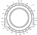
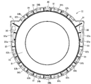
ここにおいて、押圧部材72の取付筒部80には、周上に複数の圧入突部82が形成されている。圧入突部82は、図9,16に示すように、取付筒部80の内周面に突出形成されており、圧入突部82の形成部分で取付筒部80の軸直角方向の内法寸法が周上部分的に小さくなっている。これにより、取付筒部80の内法寸法は、圧入突部82の形成部分において、第二の取付部材18における圧入部42の軸直角方向の外形寸法よりも小さくされている一方、圧入突部82を周方向に外れた部分において、圧入部42の軸直角方向の外形寸法よりも大きくされている。また、本実施形態の各圧入突部82は、周方向および軸方向にそれぞれ所定の長さで連続して延びており、圧入突部82の突出先端が第二の取付部材18における圧入部42の外周面に対応する面とされている。更に、圧入突部82の突出先端面は、周方向に湾曲して広がっていると共に、軸方向には実質的に非傾斜でストレートに延びている。更にまた、圧入突部82は、軸方向で取付筒部80の基端まで達する長さで形成されており、取付筒部80の軸方向全長に亘って連続的に設けられている。
Here, a plurality of press-fitting protrusions 82 are formed on the circumference of the mounting cylinder portion 80 of the pressing member 72. As shown in FIGS. 9 and 16, the press-fit projection 82 is formed to project from the inner peripheral surface of the mounting cylinder portion 80, and the inner dimension in the direction perpendicular to the axis of the mounting cylinder portion 80 at the portion where the press-fit projection 82 is formed. Is partially smaller on the circumference. As a result, the internal dimension of the mounting cylinder portion 80 is made smaller than the outer dimension in the direction perpendicular to the axis of the press-fit portion 42 of the second mounting member 18 at the portion where the press-fit projection 82 is formed. In the part which removed 82 from the circumferential direction, it is made larger than the external dimension of the press-fit part 42 in the direction perpendicular to the axis. In addition, each press-fit protrusion 82 of the present embodiment continuously extends in the circumferential direction and the axial direction by a predetermined length, and the protrusion tip of the press-fit protrusion 82 is the press-fit part 42 in the second mounting member 18. It is set as the surface corresponding to the outer peripheral surface. Furthermore, the projecting front end surface of the press-fit projection 82 is curved and widened in the circumferential direction, and extends substantially straight and non-inclined in the axial direction. Furthermore, the press-fitting protrusion 82 is formed with a length that reaches the proximal end of the mounting cylinder 80 in the axial direction, and is continuously provided over the entire axial length of the mounting cylinder 80.
また、押圧部材72の環状板部78には、周上の複数箇所に伝達防止部としての伝達防止孔84が形成されている。伝達防止孔84は、環状板部78を厚さ方向上下に貫通して形成されており、周方向に所定の長さで延びる略角丸矩形断面を有している。本実施形態では、複数の伝達防止孔84が略全周に亘って分散して配置されていると共に、比較的に変形剛性の大きくなる一対の固定部36,36への対応部分に形成された伝達防止孔84aが、他の伝達防止孔84bよりも周方向の長さを大きくされている。また、本実施形態の伝達防止孔84は、複数の圧入突部82と周方向で同じ位置に形成されており、圧入突部82の内周面の軸方向延長線を含む部分に開口形成されている。換言すれば、上面視において、伝達防止孔84の外周端が圧入突部82の内周端まで達している。なお、環状板部78の下面に設けられた補強リブ81は、環状板部78における伝達防止孔84の開口部分を外れて配置されている。
Further, the annular plate portion 78 of the pressing member 72 is formed with transmission preventing holes 84 as transmission preventing portions at a plurality of locations on the circumference. The transmission preventing hole 84 is formed so as to penetrate the annular plate portion 78 vertically in the thickness direction, and has a substantially rounded rectangular cross section extending a predetermined length in the circumferential direction. In the present embodiment, the plurality of transmission preventing holes 84 are arranged so as to be distributed over substantially the entire circumference, and are formed at a portion corresponding to the pair of fixing portions 36 and 36 having relatively large deformation rigidity. The transmission preventing hole 84a has a greater circumferential length than the other transmission preventing holes 84b. Further, the transmission preventing hole 84 of the present embodiment is formed at the same position in the circumferential direction as the plurality of press-fit protrusions 82, and is formed in a portion including the axial extension line of the inner peripheral surface of the press-fit protrusion 82. ing. In other words, the outer peripheral end of the transmission preventing hole 84 reaches the inner peripheral end of the press-fit protrusion 82 in a top view. Note that the reinforcing rib 81 provided on the lower surface of the annular plate portion 78 is disposed away from the opening portion of the transmission preventing hole 84 in the annular plate portion 78.
さらに、伝達防止孔84の周方向長さ寸法が、同じ位置に形成された圧入突部82の周方向長さ寸法と略同じとされている。従って、伝達防止孔84aに対応する位置に設けられる圧入突部82aが、伝達防止孔84bに対応する位置に設けられる圧入突部82bよりも、周方向の長さを大きくされている。なお、伝達防止孔84の周方向長さ寸法は、圧入突部82の周方向長さ寸法よりも小さくされていても良いが、圧入突部82の周方向長さ寸法以上とされて、圧入突部82が伝達防止孔84の周方向中間部分に配置されていることが望ましい。
Further, the circumferential length of the transmission preventing hole 84 is substantially the same as the circumferential length of the press-fit protrusion 82 formed at the same position. Accordingly, the press-fit protrusion 82a provided at a position corresponding to the transmission preventing hole 84a is made longer in the circumferential direction than the press-fit protrusion 82b provided at a position corresponding to the transmission preventing hole 84b. The circumferential length dimension of the transmission preventing hole 84 may be smaller than the circumferential length dimension of the press-fit protrusion 82, but it is not less than the circumferential length dimension of the press-fit protrusion 82. It is desirable that the protrusion 82 is disposed at the intermediate portion in the circumferential direction of the transmission preventing hole 84.
また、押圧部材72の環状板部78において第二の取付部材18の一対の固定部36,36に対応する部分には、それぞれ位置決め孔86が形成されている。位置決め孔86は、伝達防止孔84aを周方向に外れた部分に形成されており、略一定の角丸矩形断面で環状板部78を上下に貫通している。
Further, positioning holes 86 are formed in portions corresponding to the pair of fixing portions 36 and 36 of the second mounting member 18 in the annular plate portion 78 of the pressing member 72. The positioning hole 86 is formed in a portion away from the transmission preventing hole 84a in the circumferential direction, and penetrates the annular plate portion 78 vertically with a substantially constant rounded rectangular cross section.
そして、押圧部材72のシール筒部74が仕切部材58に対して外挿されており、押圧部材72の環状当接部76の上には、載置された仕切部材58の下端面との間で可撓性膜60の環状シール部68が挟まれて保持されている。また、第二の取付部材18が押圧部材72の取付筒部80に差し入れられて、押圧部材72の環状板部78が、第二の取付部材18における当接部44の下端面に重ね合わされていると共に、押圧部材72の取付筒部80が第二の取付部材18の圧入部42の外周面に重ね合わされている。更に、図18に拡大して示されているように、第二の取付部材18の圧入部42は、押圧部材72の取付筒部80における圧入突部82の形成部分に圧入されており、それによって、押圧部材72が第二の取付部材18に組み付けられていると共に、第二の取付部材18と取付筒部80の間には軸方向の抜けに対する抗力が作用している。図18にも示されているように、圧入突部82を周方向に外れた部分では、取付筒部80の内周面と第二の取付部材18の外周面との間に隙間が形成されている。
And the seal cylinder part 74 of the pressing member 72 is extrapolated with respect to the partition member 58, and it is on the annular contact part 76 of the pressing member 72 between the lower end surfaces of the partition member 58 mounted. Thus, the annular seal portion 68 of the flexible membrane 60 is sandwiched and held. Further, the second mounting member 18 is inserted into the mounting tube portion 80 of the pressing member 72, and the annular plate portion 78 of the pressing member 72 is overlapped with the lower end surface of the contact portion 44 of the second mounting member 18. In addition, the mounting cylinder portion 80 of the pressing member 72 is overlapped with the outer peripheral surface of the press-fit portion 42 of the second mounting member 18. Further, as shown in an enlarged view in FIG. 18, the press-fit portion 42 of the second mounting member 18 is press-fitted into the formation portion of the press-fit protrusion 82 in the mounting cylinder portion 80 of the pressing member 72. As a result, the pressing member 72 is assembled to the second mounting member 18, and a resistance against the axial disconnection acts between the second mounting member 18 and the mounting cylinder 80. As shown in FIG. 18, a gap is formed between the inner peripheral surface of the mounting cylinder 80 and the outer peripheral surface of the second mounting member 18 at a portion where the press-fitting protrusion 82 is removed in the circumferential direction. ing.
また、第二の取付部材18が取付筒部80に圧入されることによって、周上における圧入突部82の形成部分では抜け抗力に対する反力が取付筒部80に及ぼされて、取付筒部80に応力が作用する。この応力は、環状板部78を介してシール筒部74側へ伝達されるが、その伝達経路上に伝達防止孔84が形成されていることから、シール筒部74への応力伝達が低減されている。これにより、シール筒部74の変形量が低減されて、シール筒部74の内周面が仕切部材58の外周面に重ね合わされた状態に保持される。
In addition, when the second mounting member 18 is press-fitted into the mounting cylinder portion 80, a reaction force against the pull-out drag force is exerted on the mounting cylinder portion 80 at the formation portion of the press-fitting protrusion 82 on the periphery, and the mounting cylinder portion 80. Stress acts on This stress is transmitted to the seal cylinder part 74 side via the annular plate part 78. Since the transmission preventing hole 84 is formed on the transmission path, the stress transmission to the seal cylinder part 74 is reduced. ing. Thereby, the deformation amount of the seal cylinder part 74 is reduced, and the inner peripheral surface of the seal cylinder part 74 is held in a state of being overlapped with the outer peripheral surface of the partition member 58.
なお、本実施形態では、第二の取付部材18の一対の固定部36,36が押圧部材72の取付筒部80の内周面に周方向で係止されることにより、第二の取付部材18と押圧部材72の周方向への相対回転量が制限されている。更に、第二の取付部材18の一対の固定部36,36にそれぞれ形成された挿通ピン40が、押圧部材72の環状板部78に形成された位置決め孔86に挿通されることによって、第二の取付部材18と押圧部材72の軸直角方向での相対的な位置が相互に合わせられるようになっている。そして、それら挿通ピン40の位置決め孔86に対する周方向での係止と、第二の取付部材18の一対の固定部36,36と取付筒部80の内周面との周方向での係止とによって、第二の取付部材18と押圧部材72を周方向で相対的に位置決めする位置決め手段が構成されている。
In the present embodiment, the pair of fixing portions 36, 36 of the second mounting member 18 are locked in the circumferential direction on the inner peripheral surface of the mounting cylinder portion 80 of the pressing member 72, whereby the second mounting member. The amount of relative rotation of 18 and the pressing member 72 in the circumferential direction is limited. Further, the insertion pins 40 respectively formed in the pair of fixing portions 36 and 36 of the second mounting member 18 are inserted into the positioning holes 86 formed in the annular plate portion 78 of the pressing member 72, whereby the second The relative positions of the mounting member 18 and the pressing member 72 in the direction perpendicular to the axis can be matched with each other. And the locking in the circumferential direction with respect to the positioning hole 86 of these insertion pins 40, and the locking in the circumferential direction of a pair of fixing parts 36 and 36 of the 2nd attachment member 18, and the internal peripheral surface of the attachment cylinder part 80 The positioning means for relatively positioning the second mounting member 18 and the pressing member 72 in the circumferential direction is configured.
このように第二の取付部材18の取付筒部80への圧入によって押圧部材72が第二の取付部材18に組み付けられることにより、押圧部材72の内部に収容状態で位置決めされた仕切部材58と可撓性膜60が、第二の取付部材18の下側に重ね合わされて組み付けられている。そして、本体ゴム弾性体20の大径凹所48と可撓性膜60との軸方向対向面間には、外部空間に対して流体密に封止されて非圧縮性流体が封入された流体室88が画成されている。
In this way, the pressing member 72 is assembled to the second mounting member 18 by press-fitting the second mounting member 18 into the mounting cylinder portion 80, and thereby the partition member 58 positioned in the accommodated state inside the pressing member 72. The flexible film 60 is assembled by being superimposed on the lower side of the second attachment member 18. A fluid in which an incompressible fluid is sealed between the large-diameter recess 48 of the main rubber elastic body 20 and the axially opposing surfaces of the flexible membrane 60 in a fluid-tight manner with respect to the external space. A chamber 88 is defined.
また、かかる流体室88は、仕切部材58によって仕切られており、仕切部材58の上側には、壁部の一部が本体ゴム弾性体20で構成されて、第一及び第二の取付部材16,18間への略マウント軸方向への振動入力時に本体ゴム弾性体20の弾性変形に基づいて圧力変動が直接的に惹起される受圧室90が形成されている。一方、仕切部材58の下側には、壁部の一部が可撓性膜60で構成されて、可撓性膜60の可撓変形に基づいて内部の圧力変動が吸収軽減され得る平衡室92が形成されている。
In addition, the fluid chamber 88 is partitioned by a partition member 58, and a part of the wall portion is configured by the main rubber elastic body 20 on the upper side of the partition member 58, and the first and second mounting members 16. , 18 is formed with a pressure receiving chamber 90 in which a pressure fluctuation is directly induced based on elastic deformation of the main rubber elastic body 20 when vibration is input in a substantially mount axis direction. On the other hand, below the partition member 58, a part of the wall portion is made of the flexible film 60, and the internal pressure fluctuation can be absorbed and reduced based on the flexible deformation of the flexible film 60. 92 is formed.
更にまた、これら受圧室90と平衡室92は、仕切部材58に形成されたオリフィス通路66を通じて相互に連通されており、受圧室90と平衡室92の相対的な圧力変動に基づいてオリフィス通路66を通じて封入流体が流動せしめられるようになっている。而して、オリフィス通路66を流動する流体の共振作用等を利用して、入力振動に対する防振効果が発揮されるようになっている。
Furthermore, the pressure receiving chamber 90 and the equilibrium chamber 92 communicate with each other through an orifice passage 66 formed in the partition member 58, and the orifice passage 66 is based on the relative pressure fluctuation between the pressure receiving chamber 90 and the equilibrium chamber 92. The sealed fluid is allowed to flow through. Thus, the vibration isolating effect against the input vibration is exhibited by utilizing the resonance action of the fluid flowing through the orifice passage 66.
なお、流体室88への非圧縮性流体の注入は、例えば本体ゴム弾性体20の一体加硫成形品に対する仕切部材58や可撓性膜60、押圧部材72の組み付けを非圧縮性流体中で行うこと等によっても実現可能であるが、本実施形態では、それら各部材の組付後に、注入用孔50を通じて非圧縮性流体を注入し、その後に、かかる注入用孔50に封止用の球体を圧入固着することによって為され得る。
The incompressible fluid is injected into the fluid chamber 88 by, for example, assembling the partition member 58, the flexible film 60, and the pressing member 72 to the integrally vulcanized molded product of the main rubber elastic body 20 in the incompressible fluid. However, in this embodiment, after assembling these members, an incompressible fluid is injected through the injection hole 50 and then the sealing hole 50 is sealed. This can be done by press-fitting the sphere.
ここにおいて、本体ゴム弾性体20の一体加硫成形品に対して仕切部材58や可撓性膜60、押圧部材72を組み付けた状態、即ちアウタブラケット14の下側部分へ組み付けられる前のマウント本体12単体の状態では、流体室88の外部空間に対する封止が、第二の取付部材18の押圧部材72に対する圧入による仮封止によって実現されている。
Here, the mount body before the partition member 58, the flexible membrane 60, and the pressing member 72 are assembled to the integrally vulcanized molded product of the main rubber elastic body 20, that is, before being assembled to the lower portion of the outer bracket 14. In the state of 12 single bodies, sealing with respect to the external space of the fluid chamber 88 is realized by temporary sealing by press-fitting the pressing member 72 of the second mounting member 18.
すなわち、押圧部材72は、その環状当接部76に対して可撓性膜60の環状シール部68を挟んで仕切部材58が重ね合わされており、それら環状当接部76と仕切部材58との間で環状シール部68に軸方向の押圧力を及ぼし得るようになっている。また、押圧部材72のシール筒部74に収容された仕切部材58の上面が、当接部44よりも内周側の第二の取付部材18の下端面に対して、シールゴム52を挟んで重ね合わされており、それら仕切部材58と第二の取付部材18との間でシールゴム52に軸方向の押圧力を及ぼし得るようになっている。
That is, the pressing member 72 has a partition member 58 superimposed on the annular contact portion 76 with the annular seal portion 68 of the flexible membrane 60 interposed therebetween, and the annular contact portion 76 and the partition member 58 are overlapped. In the meantime, an axial pressing force can be applied to the annular seal portion 68. Further, the upper surface of the partition member 58 accommodated in the seal cylinder portion 74 of the pressing member 72 is overlapped with the lower end surface of the second mounting member 18 on the inner peripheral side with respect to the contact portion 44 with the seal rubber 52 interposed therebetween. Thus, an axial pressing force can be exerted on the seal rubber 52 between the partition member 58 and the second mounting member 18.
これにより、これら環状シール部68とシールゴム52とを軸方向に押圧する反力が、第二の取付部材18と押圧部材72の間で軸方向離隔側に向かって及ぼされている。そして、押圧部材72は、第二の取付部材18が押圧部材72に圧入されることによって、かかる押圧反力に抗して、第二の取付部材18に対して軸方向の接近位置に保持されている。その結果、第二の取付部材18の押圧部材72への圧入による摩擦力などの保持力をもって、環状シール部68とシールゴム52とに対して軸方向のシール圧力が及ぼされているのであり、これら各シール部52,68によって第二の取付部材18と仕切部材58の間および仕切部材58と押圧部材72との間が、それぞれ流体密に仮封止されて、流体室88の流体密性が保持されるようになっている。
Thus, a reaction force that presses the annular seal portion 68 and the seal rubber 52 in the axial direction is exerted between the second mounting member 18 and the pressing member 72 toward the axially separated side. The pressing member 72 is held in the axial approach position with respect to the second mounting member 18 against the pressing reaction force when the second mounting member 18 is press-fitted into the pressing member 72. ing. As a result, the axial seal pressure is exerted on the annular seal portion 68 and the seal rubber 52 with a holding force such as a frictional force caused by press-fitting the second mounting member 18 into the pressing member 72. The seal portions 52 and 68 temporarily seal the space between the second mounting member 18 and the partition member 58 and between the partition member 58 and the pressing member 72, respectively, so that the fluid tightness of the fluid chamber 88 is improved. It is supposed to be retained.
なお、シールゴム52が、押圧部材72の環状板部78と第二の取付部材18における当接部44よりも内周部分との重ね合わせ面間にも挟まれることにより、シール性の向上が図られるようにしても良い。
The sealing rubber 52 is also sandwiched between the overlapping surfaces of the annular plate portion 78 of the pressing member 72 and the inner peripheral portion of the second mounting member 18 rather than the contact portion 44, thereby improving the sealing performance. You may be allowed to.
また、第二の取付部材18が押圧部材72の取付筒部80に圧入されると、取付筒部80には径方向で押し広げる向きの力が作用する。そして、取付筒部80に作用する圧入に伴う応力は、環状板部78を介してシール筒部74に伝達される。ここにおいて、取付筒部80には圧入突部82が形成されており、第二の取付部材18が圧入突部82の形成部分で取付筒部80に対して周上部分的に圧入されていると共に、環状板部78の周上において各圧入突部82と同じ周方向位置には、それぞれ伝達防止孔84が形成されている。
Further, when the second mounting member 18 is press-fitted into the mounting cylinder portion 80 of the pressing member 72, a force in a direction of expanding in the radial direction acts on the mounting cylinder portion 80. Then, the stress accompanying the press-fitting that acts on the mounting cylinder part 80 is transmitted to the seal cylinder part 74 via the annular plate part 78. Here, a press-fitting protrusion 82 is formed in the mounting cylinder 80, and the second mounting member 18 is partially press-fitted in the circumferential direction with respect to the mounting cylinder 80 at a portion where the press-fitting protrusion 82 is formed. In addition, transmission preventing holes 84 are formed at the same circumferential positions as the press-fitting protrusions 82 on the circumference of the annular plate portion 78.
これにより、第二の取付部材18の取付筒部80への圧入に伴う応力が、周上で圧入突部82が形成された部分に主として作用すると共に、取付筒部80における圧入突部82の形成部分からシール筒部74に伝達される応力が、応力のシール筒部74への伝達部分に形成された伝達防止孔84によって低減される。即ち、伝達防止孔84が圧入突部82と同じ周方向位置に形成されることにより、周上で圧入突部82が形成された部分において取付筒部80および環状板部78が変形し易くなっており、変形剛性の低減によってシール筒部74に伝達される圧入に伴う応力が低減される。
Thereby, the stress accompanying the press-fitting of the second mounting member 18 into the mounting cylinder part 80 mainly acts on the portion where the press-fitting projection 82 is formed on the circumference, and the press-fitting projection 82 of the mounting cylinder part 80 The stress transmitted from the forming part to the seal cylinder part 74 is reduced by the transmission preventing hole 84 formed in the part where the stress is transmitted to the seal cylinder part 74. That is, the transmission preventing hole 84 is formed at the same circumferential position as the press-fitting protrusion 82, so that the mounting tube portion 80 and the annular plate portion 78 are easily deformed at the portion where the press-fitting protrusion 82 is formed on the circumference. Therefore, the stress accompanying the press-fitting transmitted to the seal cylinder 74 is reduced by reducing the deformation rigidity.
それ故、圧入に伴う応力の伝達に起因するシール筒部74の変形が低減乃至は防止されて、シール筒部74の内周面と仕切部材58の外周面との間に大きな隙間が形成されるのを回避できる。従って、シールゴム52がシール筒部74と仕切部材58の径方向間に入り込むなどの不具合を回避して、目的とするシール性能を有効に得ることができる。
Therefore, deformation of the seal cylinder part 74 due to the transmission of stress accompanying press-fitting is reduced or prevented, and a large gap is formed between the inner peripheral surface of the seal cylinder part 74 and the outer peripheral surface of the partition member 58. Can be avoided. Therefore, it is possible to avoid problems such as the seal rubber 52 entering between the seal cylinder portion 74 and the partition member 58 in the radial direction, and to effectively obtain the target seal performance.
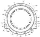
かくの如き構造とされたマウント本体12には、アウタブラケット14が取り付けられており、アウタブラケット14の略中央に形成された組付スペース内にマウント本体12が側方から差し入れられるようにして組み付けられている。なお、アウタブラケット14は、鉄やアルミニウム合金などで形成された高剛性の部材であって、軽量で且つ部材厚による剛性確保も容易であって設計自由度も大きい等の理由から、アルミニウム合金製のダイキャスト成形品が好適に採用される。
An outer bracket 14 is attached to the mount body 12 having such a structure, and the mount body 12 is assembled so that the mount body 12 can be inserted from the side into an assembly space formed substantially at the center of the outer bracket 14. It has been. The outer bracket 14 is a high-rigidity member formed of iron, aluminum alloy, or the like, and is lightweight and easy to ensure rigidity due to the thickness of the member. The die-cast molded product is preferably employed.
詳細には、図1~3に示されているように、アウタブラケット14は、組付スペースを跨いで設けられた門形部94を有しており、この門形部94の両脚下端には、相互に離隔する方向に広がる平板形状をもって一対のベース部96,96が設けられている。これらのベース部96,96のそれぞれには、固定ボルトを挿通する挿通孔98が形成されており、この挿通孔98に挿通される固定ボルトにより、アウタブラケット14が車両ボデーに対してボルト固定可能とされている。なお、門形部94の両脚部分と各ベース部96との間には、部材幅方向の両縁をつなぐ補強部100,100がそれぞれ一体形成されている。
In detail, as shown in FIGS. 1 to 3, the outer bracket 14 has a gate-shaped portion 94 provided so as to straddle the assembling space. A pair of base portions 96, 96 are provided having a flat plate shape extending in a direction away from each other. Each of these base portions 96, 96 is formed with an insertion hole 98 through which a fixing bolt is inserted, and the outer bracket 14 can be bolted to the vehicle body by the fixing bolt inserted through the insertion hole 98. It is said that. Reinforcing portions 100 and 100 that connect both edges in the member width direction are integrally formed between both leg portions of the gate-shaped portion 94 and each base portion 96.
また、門形部94の下端開口部分には、一対のベース部96,96間に跨がって広がる押圧底部102が一体形成されている。押圧底部102の中央部分には、円形の透孔104が形成されており、この透孔104の内径寸法が、マウント本体12の押圧部材72の環状当接部76の内径寸法と略同じとされている。
In addition, a pressing bottom portion 102 that extends across a pair of base portions 96 and 96 is integrally formed at the lower end opening portion of the portal portion 94. A circular through hole 104 is formed in the central portion of the pressing bottom portion 102, and the inner diameter dimension of the through hole 104 is substantially the same as the inner diameter dimension of the annular contact portion 76 of the pressing member 72 of the mount body 12. ing.
更にまた、門形部94には、一方の側方開口の下側部分を覆うように側方竪壁106が一体形成されている。この側方竪壁106は、押圧底部102の透孔104と略同心的に略円弧状に湾曲しており、門形部94の一方の側方開口から外方に向かって突出されている。
Furthermore, a side wall 106 is integrally formed on the portal portion 94 so as to cover the lower portion of one side opening. The side wall 106 is curved in a substantially arc shape substantially concentrically with the through hole 104 of the pressing bottom portion 102, and protrudes outward from one side opening of the portal portion 94.
そして、かかる側方竪壁106が設けられることで、門形部94の下側部分には、周方向に半周以上の長さで延びる略円弧状の周壁内面108と、透孔104を有する押圧底部102とを備えた組付スペースとしてのマウントホルダ部110が形成されている。かかるマウントホルダ部110は、側方竪壁106と反対側に向かって開口しており、かかる開口部が、マウント本体12を差し入れられて組み付ける差入口となっている。
By providing the side wall 106, a pressing portion having a substantially arc-shaped peripheral wall inner surface 108 extending in a circumferential direction with a length of a half or more in the circumferential direction and a through hole 104 in the lower portion of the portal portion 94. A mount holder portion 110 is formed as an assembly space including the bottom portion 102. The mount holder portion 110 is opened toward the side opposite to the side wall 106, and the opening portion serves as an insertion port into which the mount body 12 is inserted and assembled.
また、マウントホルダ部110の周壁内面108には、門形部94の一対の脚部112,112の対向内面において、押圧底部102の上面と上下方向に対向する段差状の押圧天面114が形成されている。そして、これら押圧底部102上面と押圧天面114との対向面間において、差入口に向かって開口する挟持溝116,116が形成されている。
Further, on the inner surface 108 of the peripheral wall of the mount holder portion 110, a step-like pressing top surface 114 is formed on the opposing inner surfaces of the pair of legs 112, 112 of the gate-shaped portion 94 so as to face the upper surface of the pressing bottom portion 102 in the vertical direction. Has been. And between the opposing surfaces of these press bottom part 102 upper surfaces and the press top surface 114, the clamping grooves 116 and 116 opened toward an entrance are formed.
なお、本実施形態では、マウントホルダ部110における一対の脚部112,112の内面において、高さ方向中間部分を脚部112の幅方向(図2中の紙面直交方向)の略全長に亘って延びる段差118が形成されており、段差118より下方の押圧底部102側が、段差118より上方の押圧天面114側に比して大径の内周面形状とされている。
In the present embodiment, on the inner surfaces of the pair of leg portions 112, 112 in the mount holder portion 110, the intermediate portion in the height direction extends over substantially the entire length of the leg portion 112 in the width direction (the direction perpendicular to the paper surface in FIG. 2). An extending step 118 is formed, and the pressing bottom portion 102 side below the step 118 has an inner peripheral surface shape having a larger diameter than the pressing top surface 114 side above the step 118.
また、門形部94の一対の脚部112,112の対向内面に形成された挟持溝116,116の溝底面120,120は、マウントホルダ部110におけるマウント本体12の差入口側に向かって次第に対向面間距離が大きくなるように拡開する傾斜面とされている。また、これら傾斜した溝底面120,120の傾斜角度が、マウント本体12における第二の取付部材18の一対の固定部36,36における外周面38,38の傾斜角度に対応して、略同じとされている。
Further, the groove bottom surfaces 120 and 120 of the holding grooves 116 and 116 formed on the opposing inner surfaces of the pair of leg portions 112 and 112 of the gate-shaped portion 94 gradually move toward the inlet side of the mount body 12 in the mount holder portion 110. It is set as the inclined surface which spreads so that the distance between opposing surfaces may become large. The inclined angles of the inclined groove bottom surfaces 120 and 120 are substantially the same as the inclined angles of the outer peripheral surfaces 38 and 38 of the pair of fixing portions 36 and 36 of the second mounting member 18 in the mount body 12. Has been.
そして、このような構造とされたアウタブラケット14に対して、マウント本体12が、マウントホルダ部110の側方から差し入れられて組み付けられている。そして、マウント本体12の第二の取付部材18よりも軸方向下側部分が、差入口から挟持溝116に嵌め入れられて嵌合固定されている。
The mount main body 12 is inserted into the outer bracket 14 having such a structure from the side of the mount holder portion 110 and assembled. The lower part of the mount body 12 in the axial direction than the second mounting member 18 is fitted into the holding groove 116 from the inlet and is fixedly fitted.
すなわち、第二の取付部材18における一対の固定部36,36が、挟持溝116,116に対して差入口から差し入れられることにより、各固定部36,36の外周面38,38が挟持溝116,116の各溝底面120,120に当接せしめられる。これにより、各固定部36,36が各挟持溝116,116に対して圧入状態で嵌着固定されている。
That is, the pair of fixing portions 36 and 36 in the second mounting member 18 are inserted into the holding grooves 116 and 116 from the entrance, so that the outer peripheral surfaces 38 and 38 of the fixing portions 36 and 36 are held in the holding grooves 116. , 116 are brought into contact with the groove bottom surfaces 120, 120. Thereby, each fixing | fixed part 36 and 36 is engage | inserted and fixed by the press-fit state with respect to each clamping groove | channel 116,116.
また、本実施形態では、挟持溝116,116の各溝底面120,120が傾斜面とされており、アウタブラケット14の型成形時における脱型に際して、型抜テーパとして利用され得る。これにより、アウタブラケット14のダイキャスト成形の作業が一層容易とされ得る。更に、一対の挟持溝116,116における溝底面120,120の対向面間距離が、挟持溝116の差入口に向かって次第に拡開するように傾斜していることから、マウントホルダ部110内にマウント本体12を差し入れることも容易に可能とされる。
Further, in this embodiment, the groove bottom surfaces 120 and 120 of the holding grooves 116 and 116 are inclined surfaces, and can be used as a die-cut taper when the outer bracket 14 is removed during mold forming. Thereby, the operation | work of die-cast shaping | molding of the outer bracket 14 can be made still easier. Furthermore, since the distance between the opposed surfaces of the groove bottom surfaces 120 and 120 in the pair of sandwiching grooves 116 and 116 is inclined so as to gradually expand toward the entrance of the sandwiching groove 116, The mount body 12 can be easily inserted.
さらに、マウント本体12は、アウタブラケット14の挟持溝116に嵌め入れられることにより、第二の取付部材18と押圧部材72とに対して、軸方向で相互に接近する方向の押圧力が及ぼされている。即ち、図6,7に示されている如きマウント本体12の単体においては、第二の取付部材18が押圧部材72の取付筒部80に圧入されることによって、仮封止状態のシールゴム52と環状シール部68の押圧反力に対する抗力が発揮されている。かかる仮封止状態下での第二の取付部材18の上端面と押圧部材72の下端面との間のマウント軸方向距離に比して、アウタブラケット14の挟持溝116における押圧底部102上面と押圧天面114との対向面間距離が小さく設定されている。
Further, the mount main body 12 is fitted into the holding groove 116 of the outer bracket 14, thereby exerting a pressing force in the axial direction toward the second mounting member 18 and the pressing member 72. ing. That is, in the single body of the mount body 12 as shown in FIGS. 6 and 7, the second mounting member 18 is press-fitted into the mounting cylinder portion 80 of the pressing member 72, so that the temporarily sealed seal rubber 52 and A resistance against the pressing reaction force of the annular seal portion 68 is exhibited. Compared to the distance in the mount axial direction between the upper end surface of the second mounting member 18 and the lower end surface of the pressing member 72 in such a temporarily sealed state, the upper surface of the pressing bottom portion 102 in the holding groove 116 of the outer bracket 14 The distance between the opposing surfaces with the pressing top surface 114 is set small.
これにより、仮封止状態のマウント本体12がアウタブラケット14の挟持溝116に嵌め入れられると、図19に拡大図示されているように、第二の取付部材18と押圧部材72とが、マウント軸方向で更に相互に接近方向へ相対変位せしめられ、その分だけシールゴム52と環状シール部68に対して更なる圧縮がおよぼされる。この状態でマウント本体12の第二の取付部材18がアウタブラケット14に組付固定されることで、本封止状態とされて流体室88に高度な流体密性が設定されている。
As a result, when the temporarily sealed mount body 12 is fitted into the holding groove 116 of the outer bracket 14, the second mounting member 18 and the pressing member 72 are mounted as shown in FIG. In the axial direction, they are further displaced relative to each other in the approaching direction, and further compression is applied to the seal rubber 52 and the annular seal portion 68 accordingly. In this state, the second mounting member 18 of the mount body 12 is assembled and fixed to the outer bracket 14, so that the fluid chamber 88 is set to a high degree of fluid tightness.
このように、本実施形態のエンジンマウント10は、アウタブラケット14の第二の取付部材18への装着によって本封止状態とされることから、第二の取付部材18を押圧部材72の取付筒部80に圧入したマウント本体12では、高度な流体密性や大きな抜け抗力は必要とされない。それ故、第二の取付部材18の外形寸法と取付筒部80における圧入突部82の形成部分での内法寸法との差(圧入代)を比較的に小さく設定して、取付筒部80に作用する圧入に伴う応力が低減される。
As described above, the engine mount 10 of the present embodiment is brought into the main sealing state by mounting the outer bracket 14 to the second mounting member 18, and thus the second mounting member 18 is attached to the pressing member 72 mounting cylinder. The mount main body 12 press-fitted into the portion 80 does not require a high degree of fluid tightness or a large slip resistance. Therefore, the difference between the outer dimension of the second mounting member 18 and the internal dimension of the mounting cylinder portion 80 where the press-fitting protrusion 82 is formed (press-fitting allowance) is set to be relatively small. Stress due to press-fitting that acts on is reduced.
本実施形態では、押圧部材72の環状当接部76に対して、アウタブラケット14の押圧底部102が、押圧部材72の下面において周上で全周に亘って押圧している。一方、第二の取付部材18の上面に対して、挟持溝116の押圧天面114が、第二の取付部材18の周上で部分的に押圧している。
In the present embodiment, the pressing bottom portion 102 of the outer bracket 14 presses the entire circumference of the lower surface of the pressing member 72 against the annular contact portion 76 of the pressing member 72. On the other hand, the pressing top surface 114 of the holding groove 116 is partially pressed against the upper surface of the second mounting member 18 on the circumference of the second mounting member 18.
なお、アウタブラケット14の挟持溝116の底壁部分に対して潰しカシメ加工を施すことによって、マウント本体12の第二の取付部材18に差入れ方向で係合するカシメ係合部を形成して、第二の取付部材18の固定部36,36がアウタブラケット14の挟持溝116,116から抜け出すことを防止しても良い。
A crimping engagement portion that engages the second mounting member 18 of the mount body 12 in the insertion direction is formed by crushing and crimping the bottom wall portion of the holding groove 116 of the outer bracket 14. The fixing portions 36 and 36 of the second mounting member 18 may be prevented from coming out of the holding grooves 116 and 116 of the outer bracket 14.
このようにマウント本体12がアウタブラケット14に組み付けられた組付体における第一の取付部材16の中空孔22に対して、インナブラケット32が先端側から挿入されて、エンジンマウント10が構成されている。
In this way, the inner bracket 32 is inserted into the hollow hole 22 of the first mounting member 16 in the assembly in which the mount body 12 is assembled to the outer bracket 14, and the engine mount 10 is configured. Yes.
より詳細には、第一の取付部材16の中空孔22に対して、アウタブラケット14へのマウント本体12の差入方向と反対の方向から、インナブラケット32の先端側が挿入される。この中空孔22の内面には嵌着ゴム層28が被着形成されており、インナブラケット32の先端部分の外周寸法が中空孔22の寸法と略等しくされていることから、インナブラケット32は中空孔22に対して、嵌着ゴム層28に当接して、または嵌着ゴム層28を僅かに圧縮して挿入される。これにより、インナブラケット32と第一の取付部材16が嵌着ゴム層28を介して密着状態で当接しており、インナブラケット32と嵌着ゴム層28との摩擦作用により、インナブラケット32の第一の取付部材16からの抜出しが効果的に防止され得る。
More specifically, the front end side of the inner bracket 32 is inserted into the hollow hole 22 of the first mounting member 16 from the direction opposite to the insertion direction of the mount body 12 to the outer bracket 14. A fitting rubber layer 28 is formed on the inner surface of the hollow hole 22, and the outer peripheral dimension of the distal end portion of the inner bracket 32 is substantially equal to the dimension of the hollow hole 22. The hole 22 is inserted into contact with the fitting rubber layer 28 or slightly compressed. As a result, the inner bracket 32 and the first mounting member 16 are in close contact with each other via the fitting rubber layer 28, and the inner bracket 32 and the first fitting member 16 are brought into contact with each other by the frictional action between the inner bracket 32 and the fitting rubber layer 28. Extraction from one mounting member 16 can be effectively prevented.
そして、図2にも示されているように、マウント本体12とアウタブラケット14とインナブラケット32とが組み付けられたエンジンマウント10では、第一の取付部材16の上側に形成されている上部緩衝ゴム層31が圧縮されて、アウタブラケット14における門形部94内面の天面に対して押し付けられている。
As shown in FIG. 2, in the engine mount 10 in which the mount body 12, the outer bracket 14, and the inner bracket 32 are assembled, the upper shock absorbing rubber formed on the upper side of the first mounting member 16. The layer 31 is compressed and pressed against the top surface of the inner surface of the portal portion 94 in the outer bracket 14.
上記の如き構造とされたエンジンマウント10は、インナブラケット32の挿通孔にボルトが挿通されてパワーユニットに固定される一方、アウタブラケット14の挿通孔98にボルトが挿通されて車両ボデーに固定される。これにより、パワーユニットと車両ボデーがエンジンマウント10により弾性連結される。なお、かかる車両装着状態では、エンジンマウント10に対してパワーユニット重量の分担荷重が及ぼされて、本体ゴム弾性体20が弾性変形せしめられる。これにより、第一の取付部材16と第二の取付部材18がマウント中心軸方向で相対的に接近方向へ変位せしめられて、所定の離隔距離をもって対向位置している。また、例えば、エンジンマウント10は、図2中の上下方向が車両の上下方向、図2中の左右方向が車両の前後または左右方向となるように、車両に装着される。
The engine mount 10 having the structure as described above is fixed to the power unit by inserting a bolt through the insertion hole of the inner bracket 32, and fixed to the vehicle body by inserting the bolt into the insertion hole 98 of the outer bracket 14. . Thereby, the power unit and the vehicle body are elastically connected by the engine mount 10. In such a vehicle mounting state, a shared load of the power unit weight is applied to the engine mount 10 and the main rubber elastic body 20 is elastically deformed. As a result, the first mounting member 16 and the second mounting member 18 are displaced relative to each other in the direction of the mount center axis in the approaching direction, and are opposed to each other with a predetermined separation distance. Further, for example, the engine mount 10 is mounted on the vehicle such that the vertical direction in FIG. 2 is the vertical direction of the vehicle and the horizontal direction in FIG.
かかるエンジンマウント10に対して、インナブラケット32を介してエンジンシェイク等の振動が入力されると、オリフィス通路66を通じて非圧縮性流体が流動することによる共振作用等により、入力振動に対する防振効果が発揮され得る。
When vibration such as an engine shake is input to the engine mount 10 via the inner bracket 32, a vibration-proofing effect against the input vibration is obtained due to a resonance action caused by the flow of the incompressible fluid through the orifice passage 66. Can be demonstrated.
ここにおいて、エンジンマウント10に対して下方への過大な振動が入力されると、インナブラケット32が図11,12に示す下部緩衝ゴム層46を介してアウタブラケット14の側方竪壁106の上端面に当接する。これにより、第一の取付部材16と第二の取付部材18のマウント中心軸方向における相対的な接近方向での変位量を緩衝的に制限する、バウンドストッパ機能が発揮され得る。
Here, if excessive downward vibration is input to the engine mount 10, the inner bracket 32 moves over the side wall 106 of the outer bracket 14 via the lower cushioning rubber layer 46 shown in FIGS. Abuts against the end face. Thereby, the bound stopper function which limits the amount of displacement in the relative approach direction in the mount central axis direction of the first mounting member 16 and the second mounting member 18 in a buffering manner can be exhibited.
一方、エンジンマウント10に対して上方への過大な振動が入力されると、第一の取付部材16が上部緩衝ゴム層31を介してアウタブラケット14における門形部94の天面に当接する。これにより、第一の取付部材16と第二の取付部材18のマウント中心軸方向における相対的な離隔方向での変位量を緩衝的に制限する、リバウンドストッパ機能が発揮され得る。
On the other hand, when excessive upward vibration is input to the engine mount 10, the first mounting member 16 comes into contact with the top surface of the portal portion 94 of the outer bracket 14 through the upper cushioning rubber layer 31. Thereby, the rebound stopper function which limits the displacement amount in the relative separation direction in the mount central-axis direction of the 1st attachment member 16 and the 2nd attachment member 18 in a buffering manner can be exhibited.
さらに、エンジンマウント10に対して車両前後または左右方向での過大な振動が入力されると、第一の取付部材16が両側方緩衝ゴム層54,54を介してアウタブラケット14における周壁内面108に当接する。これにより、第一の取付部材16と第二の取付部材18の車両前後または左右方向における相対的な変位量を緩衝的に制限する、軸直角方向ストッパ機能が発揮され得る。
Further, when excessive vibration in the vehicle front-rear or left-right direction is input to the engine mount 10, the first mounting member 16 is applied to the inner surface 108 of the outer wall 14 of the outer bracket 14 via the both-side cushioning rubber layers 54, 54. Abut. As a result, an axially perpendicular stopper function that limits the relative displacement of the first mounting member 16 and the second mounting member 18 in the vehicle front-rear or left-right direction can be exhibited.
このような本実施形態に従う構造とされたエンジンマウント10では、マウント本体12において、第二の取付部材18が押圧部材72の取付筒部80に圧入されることにより、第二の取付部材18と仕切部材58の間および仕切部材58と可撓性膜60の間がそれぞれ流体密に封止されて、流体室88に流体を封入できる。
In the engine mount 10 having the structure according to this embodiment, the second mounting member 18 is press-fitted into the mounting cylinder portion 80 of the pressing member 72 in the mount body 12, thereby Between the partition member 58 and between the partition member 58 and the flexible film 60 are sealed in a fluid tight manner, the fluid can be sealed in the fluid chamber 88.
ここにおいて、取付筒部80の内周面には複数の圧入突部82が形成されており、第二の取付部材18が圧入突部82の形成部分で取付筒部80に圧入されていると共に、圧入突部82を周方向に外れた部分では、第二の取付部材18の外周面と取付筒部80の内周面が相互に離隔している。これにより、第二の取付部材18の圧入による応力が、取付筒部80の周上における圧入突部82の形成部分に主として及ぼされるようになっている。更に、環状板部78における各圧入突部82と同じ周方向位置では、環状板部78を貫通する伝達防止孔84がそれぞれ形成されており、取付筒部80および環状板部78の変形剛性が低減されている。
Here, a plurality of press-fitting protrusions 82 are formed on the inner peripheral surface of the mounting cylinder 80, and the second mounting member 18 is press-fitted into the mounting cylinder 80 at the portion where the press-fitting protrusion 82 is formed. The outer peripheral surface of the second mounting member 18 and the inner peripheral surface of the mounting cylinder portion 80 are separated from each other at a portion where the press-fitting protrusion 82 is removed in the circumferential direction. As a result, the stress due to the press-fitting of the second mounting member 18 is mainly exerted on the forming portion of the press-fitting protrusion 82 on the circumference of the mounting cylinder portion 80. Further, at the same circumferential position as each press-fitting protrusion 82 in the annular plate portion 78, a transmission preventing hole 84 penetrating the annular plate portion 78 is formed, and the deformation rigidity of the mounting tube portion 80 and the annular plate portion 78 is reduced. Has been reduced.
これらによって、第二の取付部材18の圧入によって取付筒部80に及ぼされる応力が、環状板部78を介してシール筒部74に伝達されるのが防止されて、圧入時の応力に起因するシール筒部74の変形が制限される。その結果、シール筒部74の内周面と仕切部材58の外周面との間に隙間を生じるのが防止されることから、シールゴム52がシール筒部74と仕切部材58の間に入り込むことなく第二の取付部材18と仕切部材58の間で軸方向に圧縮されて、目的とするシール性能が安定して発揮される。
As a result, the stress exerted on the mounting cylinder part 80 by the press-fitting of the second mounting member 18 is prevented from being transmitted to the seal cylinder part 74 via the annular plate part 78, resulting from the stress at the time of press-fitting. The deformation of the seal cylinder 74 is limited. As a result, a gap is prevented from being generated between the inner peripheral surface of the seal cylinder part 74 and the outer peripheral surface of the partition member 58, so that the seal rubber 52 does not enter between the seal cylinder part 74 and the partition member 58. It is compressed in the axial direction between the second mounting member 18 and the partition member 58, and the intended sealing performance is stably exhibited.
特に本実施形態では、全ての圧入突部82に対して各一つの対応する伝達防止孔84が形成されており、それら圧入突部82と伝達防止孔84が周上の同じ位置に配されている。それ故、各圧入突部82の形成部分で取付筒部80に作用する応力が、それぞれ伝達防止孔84によって伝達を低減されて、シール筒部74の変形がより有利に防止されている。なお、本実施形態に示されているように、圧入突部82が周上で部分的に形成されていることから、伝達防止孔84を環状板部78の全周に連続して設ける必要がなく、環状板部78ひいては押圧部材72の部材強度の確保も良好に達成され得る。
In particular, in the present embodiment, one corresponding transmission prevention hole 84 is formed for each of the press-fit protrusions 82, and the press-fit protrusions 82 and the transmission prevention holes 84 are arranged at the same position on the circumference. Yes. Therefore, the stress acting on the mounting cylinder 80 at the portion where each press-fitting protrusion 82 is formed is reduced in transmission by the transmission preventing hole 84, and the deformation of the seal cylinder 74 is more advantageously prevented. As shown in the present embodiment, since the press-fitting projection 82 is partially formed on the circumference, it is necessary to provide the transmission preventing hole 84 continuously on the entire circumference of the annular plate portion 78. In addition, it is possible to satisfactorily ensure the strength of the annular plate 78 and the pressing member 72.
しかも、伝達防止孔84の周方向長さが、周上の同じ位置に配された対応する圧入突部82の周方向長さ以上とされていることにより、伝達防止孔84が圧入による応力の主たる伝達部分に対して周方向の全体に亘って形成されており、シール筒部74への応力の伝達が伝達防止孔84によって効果的に低減される。加えて、本実施形態では、伝達防止孔84の周方向長さが対応する圧入突部82の周方向長さと略同じであることから、応力伝達を有効に低減しつつ、環状板部78の強度が伝達防止孔84の形成によって小さくなり過ぎるのを回避できる。
In addition, since the circumferential length of the transmission preventing hole 84 is equal to or greater than the circumferential length of the corresponding press-fit protrusion 82 arranged at the same position on the circumference, the transmission preventing hole 84 is subjected to stress caused by the press-fitting. It is formed over the entire circumferential direction with respect to the main transmission portion, and the transmission of stress to the seal cylinder portion 74 is effectively reduced by the transmission prevention hole 84. In addition, in the present embodiment, since the circumferential length of the transmission preventing hole 84 is substantially the same as the circumferential length of the corresponding press-fit protrusion 82, the stress transmission can be effectively reduced while the annular plate portion 78. It can be avoided that the strength becomes too small due to the formation of the transmission preventing hole 84.
また、圧入突部82が周方向および軸方向にそれぞれある程度の長さで延びており、圧入突部82の突出先端が周方向および軸方向に広がる面とされている。それ故、第二の取付部材18と取付筒部80の圧入面を十分な面積で確保することができて、圧入によって発揮されるシール反力に対する抗力、換言すれば抜けに対する抗力を有効に得ることができる。
Further, the press-fit protrusion 82 extends in a certain length in the circumferential direction and the axial direction, respectively, and the protruding tip of the press-fit protrusion 82 is a surface that extends in the circumferential direction and the axial direction. Therefore, the press-fitting surfaces of the second mounting member 18 and the mounting cylinder part 80 can be secured with a sufficient area, and the resistance against the seal reaction force exerted by the press-fitting, in other words, the drag resistance against the removal can be effectively obtained. be able to.
さらに、本実施形態では、圧入突部82が取付筒部80の基端まで軸方向に延びており、圧入面積が効率的に確保されると共に、圧入時に第二の取付部材18と取付筒部80の相対的な傾斜が生じ難くなっている。しかも、圧入突部82の形成部分では、環状板部78に伝達防止孔84が形成されていることから、圧入突部82が取付筒部80の基端まで形成されていても、取付筒部80および環状板部78が圧入突部82によって補強されて応力の伝達効率が高まるのを回避することができる。特に、伝達防止孔84は、取付筒部80の内周面(圧入突部82の突出先端面)の軸方向への延長線を含む環状板部78の外周端部に形成されていることから、圧入突部82による補強作用が有利に回避されて、取付筒部80から環状板部78への応力伝達が効果的に低減される。
Furthermore, in this embodiment, the press-fit protrusion 82 extends in the axial direction to the proximal end of the mounting cylinder 80, and the press-fit area is efficiently secured, and the second mounting member 18 and the mounting cylinder at the time of press-fitting. A relative inclination of 80 is less likely to occur. In addition, since the transmission preventing hole 84 is formed in the annular plate portion 78 in the formation portion of the press-fit protrusion 82, even if the press-fit protrusion 82 is formed up to the proximal end of the attachment tube portion 80, the attachment tube portion It can be avoided that 80 and the annular plate portion 78 are reinforced by the press-fitting protrusion 82 to increase the transmission efficiency of stress. In particular, the transmission preventing hole 84 is formed at the outer peripheral end portion of the annular plate portion 78 including the extension line in the axial direction of the inner peripheral surface of the mounting cylinder portion 80 (the protruding tip end surface of the press-fit protrusion 82). The reinforcing action by the press-fitting protrusion 82 is advantageously avoided, and the stress transmission from the mounting cylinder 80 to the annular plate 78 is effectively reduced.
更にまた、圧入面を構成する圧入突部82の内周面(圧入突部82の突出先端面)と第二の取付部材18の圧入部42の外周面(圧入突部82の突出先端の当接面)とが、何れも軸方向に非傾斜で延びている。それ故、圧入面の面積が効率的に大きく確保されると共に、引っ掛かり等の少ないスムーズな圧入作業を実現しつつ、圧入によって発揮される抗力を有効に得ることができる。
Furthermore, the inner peripheral surface of the press-fit projection 82 constituting the press-fit surface (the projecting tip surface of the press-fit projecting portion 82) and the outer peripheral surface of the press-fit portion 42 of the second mounting member 18 (the projecting tip of the press-fit projecting portion 82 are in contact with each other). The contact surfaces) extend in an axially non-inclined manner. Therefore, the area of the press-fitting surface can be efficiently ensured and the drag exerted by the press-fitting can be effectively obtained while realizing a smooth press-fitting operation with little catching or the like.
尤も、圧入突部82の内周面と第二の取付部材18の圧入部42の外周面とが相対的に傾斜していても、少なくとも一部において圧入状態で目的とする抗力が発揮されていれば良い。即ち、圧入突部82と圧入部42が、軸方向で部分的に当接していると共に、他の部分ではそれら圧入突部82と圧入部42の径方向間に隙間が形成された構造も採用可能である。更には、圧入突部82の内周面と第二の取付部材18の圧入部42の外周面とが、相互に平行で且つ何れも軸方向に対して傾斜する傾斜面とされていても良く、例えば、圧入突部82の内周面が取付筒部80の上開口部に向かって拡開する傾斜面とされていれば、第二の取付部材18を取付筒部80に差し入れ易くなる。
However, even if the inner peripheral surface of the press-fit protrusion 82 and the outer peripheral surface of the press-fit portion 42 of the second mounting member 18 are relatively inclined, the target drag is exerted in at least a part in the press-fit state. Just do it. That is, a structure in which the press-fitting protrusion 82 and the press-fitting part 42 are in partial contact with each other in the axial direction, and a gap is formed between the press-fitting protrusion 82 and the press-fitting part 42 in the radial direction in the other parts. Is possible. Furthermore, the inner peripheral surface of the press-fitting protrusion 82 and the outer peripheral surface of the press-fit portion 42 of the second mounting member 18 may be inclined surfaces that are parallel to each other and are inclined with respect to the axial direction. For example, if the inner peripheral surface of the press-fitting protrusion 82 is an inclined surface that expands toward the upper opening of the mounting cylinder 80, the second mounting member 18 can be easily inserted into the mounting cylinder 80.
また、圧入突部82が取付筒部80の内周面に突出して形成されて、圧入突部82と伝達防止孔84が何れも押圧部材72に形成されている。それ故、圧入突部82と伝達防止孔84が周方向で予め相互に位置決めされて、圧入突部82の形成位置に応じて設定される応力の伝達部分に伝達防止孔84を配置することができる。
Further, the press-fitting protrusion 82 is formed so as to protrude from the inner peripheral surface of the mounting cylinder part 80, and the press-fitting protrusion 82 and the transmission preventing hole 84 are both formed in the pressing member 72. Therefore, the press-fitting protrusion 82 and the transmission preventing hole 84 are positioned in advance in the circumferential direction, and the transmission preventing hole 84 can be arranged at a stress transmission portion set according to the position where the press-fitting protrusion 82 is formed. it can.
また、本実施形態の伝達防止部が伝達防止孔84とされており、内周面が径方向で十分に離れていることから、内周面が径方向で接触乃至は近接しているスリット(切込み)などに比して、環状板部78の変形時などにも応力の伝達が有効に低減される。しかも、伝達防止孔84は、スリットなどに比して環状板部78を成形する際に形成し易く、伝達防止部を形成するための後加工なども不要になる。
In addition, since the transmission preventing portion of the present embodiment is a transmission preventing hole 84 and the inner peripheral surface is sufficiently separated in the radial direction, the inner peripheral surface is in contact with or close to the radial direction in the slit ( As compared with the notch), the transmission of stress is effectively reduced even when the annular plate portion 78 is deformed. In addition, the transmission preventing hole 84 is easier to form when the annular plate portion 78 is molded than a slit or the like, and post-processing for forming the transmission preventing portion is not necessary.
さらに、環状板部78は、複数の伝達防止孔84の形成によって低下した変形剛性が、補強リブ81によって補われている。これにより、圧入突部82の突出先端面で設定される圧入面を大きく確保すると共に、各圧入突部82からシール筒部74への応力伝達を伝達防止孔84によって有効に低減しながら、環状板部78の著しい強度の低下を防ぐことができる。特に、補強リブ81が伝達防止孔84の形成部分を外れて配置されていることから、補強リブ81によって応力伝達率が高められるのを防ぐこともできる。
Furthermore, the annular plate portion 78 is supplemented by the reinforcing rib 81 with the deformation rigidity reduced by the formation of the plurality of transmission preventing holes 84. This ensures a large press-fitting surface set by the projecting tip surface of the press-fitting projection 82, and effectively reduces stress transmission from each press-fitting projection 82 to the seal cylinder 74 by the transmission preventing hole 84. A significant decrease in strength of the plate portion 78 can be prevented. In particular, since the reinforcing rib 81 is arranged away from the portion where the transmission preventing hole 84 is formed, it is possible to prevent the stress transmission rate from being increased by the reinforcing rib 81.
以上、本発明の実施形態について詳述してきたが、本発明はその具体的な記載によって限定されない。例えば、伝達防止部は、前記実施形態で示す孔状のものに限定されず、内面が径方向で相互に当接したスリット状などの他、図20に示すような構造も採用される。即ち、図20に示された封止用部材としての押圧部材130の環状板部78には、下面に開口する凹所状乃至は切欠き状の肉抜部132が形成されており、環状板部78における肉抜部132の形成部分が、変形剛性の小さい伝達防止部としての薄肉部134とされている。このような伝達防止部によっても、圧入に伴う応力の伝達が低減される。
As mentioned above, although embodiment of this invention has been explained in full detail, this invention is not limited by the specific description. For example, the transmission preventing portion is not limited to the hole-shaped one shown in the above embodiment, and a structure as shown in FIG. 20 is also adopted in addition to a slit shape whose inner surfaces are in contact with each other in the radial direction. That is, the annular plate portion 78 of the pressing member 130 as the sealing member shown in FIG. 20 is formed with a recessed or notched hollow portion 132 opened on the lower surface. A portion where the thinned portion 132 is formed in the portion 78 is a thin portion 134 as a transmission preventing portion having a small deformation rigidity. Such a transmission preventing portion also reduces the transmission of stress accompanying press-fitting.
さらに、図21に示された封止用部材としての押圧部材140の環状板部78には、環状板部78を貫通する伝達防止孔84と、環状板部78の上面に開口して周方向に延びる凹所状乃至は凹溝状の肉抜部142とが形成されている。これにより、押圧部材140では、伝達防止孔84に加えて、肉抜部142の形成部分に設けられて肉抜部142で変形剛性が小さくされることにより応力伝達率が低下させしめられた薄肉部144によっても、環状板部78の伝達防止部が構成されている。また、薄肉部144は、各圧入突部82に対応する位置ごとに設けられていても良いが、図21に示すように、周方向に半周以上の長さで連続して設けられて、複数の圧入突部82が薄肉部144の周方向中間に配置されていても良い。更に、押圧部材140では、伝達防止部が全ての圧入突部82の内周側には設けられておらず、幾つかの圧入突部82の内周側には伝達防止孔84と薄肉部144の何れも設けられていない。図21の構造からも明らかなように、複数の互いに構造の異なる複数種類の伝達防止部を組み合わせて採用することができると共に、圧入突部82からシール筒部74への応力伝達部分の全てに伝達防止部を設ける必要はない。なお、図20,21において、第一の実施形態と実質的に同一の部材および部位については、図中に同一の符号を付すことにより、説明を省略する。
Furthermore, the annular plate portion 78 of the pressing member 140 as the sealing member shown in FIG. 21 has a transmission preventing hole 84 that penetrates the annular plate portion 78 and an upper surface of the annular plate portion 78 that opens to the circumferential direction. A hollow portion 142 having a concave shape or a concave groove shape is formed. As a result, in the pressing member 140, in addition to the transmission preventing hole 84, a thin wall is provided in a portion where the thinned portion 142 is formed and the stress transmission rate is reduced by reducing the deformation rigidity at the thinned portion 142. The portion 144 also constitutes a transmission preventing portion for the annular plate portion 78. In addition, the thin wall portion 144 may be provided at each position corresponding to each press-fitting protrusion 82, but as shown in FIG. The press-fitting protrusion 82 may be arranged in the middle in the circumferential direction of the thin portion 144. Further, in the pressing member 140, the transmission preventing part is not provided on the inner peripheral side of all the press-fitting protrusions 82, and the transmission preventing hole 84 and the thin part 144 are provided on the inner peripheral side of several press-fitting protrusions 82. None of these are provided. As is clear from the structure of FIG. 21, a plurality of different types of transmission preventing portions having different structures can be used in combination, and all of the stress transmission portions from the press-fit protrusion 82 to the seal cylinder portion 74 can be used. There is no need to provide a transmission preventing part. 20 and 21, members and portions that are substantially the same as those of the first embodiment are denoted by the same reference numerals in the drawings, and description thereof is omitted.
また、圧入突部と伝達防止部は、必ずしも周方向に同じ長さで形成されていなくても良く、それら圧入突部と伝達防止部の周方向長さが互いに異なっており、それら圧入突部と伝達防止部の何れか一方が他方よりも周方向の外側にまで延びていても良い。なお、圧入突部と伝達防止部の周方向長さが互いに異なっている場合には、伝達防止部の周方向長さが圧入突部の周方向長さよりも大きくされて、伝達防止部が圧入突部よりも周方向外側まで延びていることが望ましい。
Further, the press-fitting protrusion and the transmission preventing part do not necessarily have the same length in the circumferential direction, and the circumferential lengths of the press-fitting protrusion and the transmission preventing part are different from each other. Any one of the transmission preventing portions may extend to the outer side in the circumferential direction than the other. When the circumferential lengths of the press-fitting protrusion and the transmission preventing part are different from each other, the circumferential length of the transmission preventing part is made larger than the circumferential length of the press-fitting protrusion, and the transmission preventing part is press-fitted. It is desirable to extend to the outer side in the circumferential direction from the protrusion.
また、伝達防止部は、圧入による応力の伝達部分に形成されていれば、必ずしも圧入突部と同じ周方向位置に配される必要はない。特に、伝達防止部と圧入突部の周方向長さが相互に異なる場合には、それら伝達防止部と圧入突部が周方向で互いに異なる位置に配置され得る。
Also, if the transmission preventing portion is formed in the portion where the stress due to press-fitting is transmitted, it is not always necessary to be disposed at the same circumferential position as the press-fitting protrusion. In particular, when the circumferential lengths of the transmission preventing part and the press-fitting protrusion are different from each other, the transmission preventing part and the press-fitting protrusion can be arranged at different positions in the circumferential direction.
また、伝達防止部は、必ずしも段差部における取付筒部側の端部に形成されていなくても良く、例えば、伝達防止部は、段差部の径方向中央部分に形成されて、取付筒部に対して内周へ離れて位置せしめられていても良い。
Further, the transmission preventing portion does not necessarily have to be formed at the end of the stepped portion on the side of the mounting cylinder portion.For example, the transmission preventing portion is formed at the central portion in the radial direction of the stepped portion, On the other hand, it may be positioned away from the inner periphery.
前記第一の実施形態では、第二の取付部材18の取付筒部80への圧入によって仮シール状態のマウント本体12が構成されて、マウント本体12にアウタブラケット14が装着されることで、本シール状態のエンジンマウント10が構成されるようになっているが、例えば圧入代などを適宜に設定することで、第二の取付部材18の取付筒部80への圧入によって、流体室88に高度な流体密性が設定された本シール状態のマウント本体12が構成されるようにもできる。
In the first embodiment, the mount body 12 in a temporarily sealed state is configured by press-fitting the second mounting member 18 into the mounting cylinder portion 80, and the outer bracket 14 is attached to the mount body 12. Although the engine mount 10 in a sealed state is configured, for example, by appropriately setting a press-fitting allowance or the like, the fluid chamber 88 is advanced by press-fitting the second mounting member 18 into the mounting cylinder portion 80. It is also possible to configure the mount main body 12 in the present sealed state in which a high fluid tightness is set.
また、インナブラケットおよびアウタブラケットの具体的な構造は何等限定されるものではない。例えば、アウタブラケットにおいて、門形部の頂部を有しない構造が採用されてもよい。かかる構造のアウタブラケットが採用される場合においてリバウンドストッパ機能が必要とされる場合には、別構造のリバウンドストッパを別途採用する等してもよい。更にまた、第一の取付部材は、ブロック形状等の構造も適宜採用可能である。
Also, the specific structure of the inner bracket and the outer bracket is not limited at all. For example, in the outer bracket, a structure that does not have the top of the portal portion may be adopted. When the outer bracket having such a structure is employed, when a rebound stopper function is required, a rebound stopper having another structure may be separately employed. Furthermore, the first mounting member can adopt a structure such as a block shape as appropriate.
さらに、本発明は、エンジンマウントだけに適用されるものではなく、例えばサブフレームマウントやデフマウントなどにも適用され得る。更にまた、本発明に係る流体封入式防振装置は、自動車用に限定されるものではなく、自動二輪車や鉄道用車両、産業用車両などにも用いられ得る。
Furthermore, the present invention is not only applied to engine mounts, but can also be applied to, for example, subframe mounts and differential mounts. Furthermore, the fluid-filled vibration isolator according to the present invention is not limited to automobiles, and can be used for motorcycles, railway vehicles, industrial vehicles, and the like.