JP3658843B2 - Fluid-filled cylindrical mounting device - Google Patents
Fluid-filled cylindrical mounting device Download PDFInfo
- Publication number
- JP3658843B2 JP3658843B2 JP6654496A JP6654496A JP3658843B2 JP 3658843 B2 JP3658843 B2 JP 3658843B2 JP 6654496 A JP6654496 A JP 6654496A JP 6654496 A JP6654496 A JP 6654496A JP 3658843 B2 JP3658843 B2 JP 3658843B2
- Authority
- JP
- Japan
- Prior art keywords
- cylindrical
- fluid
- axial direction
- bracket
- outer peripheral
- Prior art date
- Legal status (The legal status is an assumption and is not a legal conclusion. Google has not performed a legal analysis and makes no representation as to the accuracy of the status listed.)
- Expired - Fee Related
Links
Images
Landscapes
- Arrangement Or Mounting Of Propulsion Units For Vehicles (AREA)
- Combined Devices Of Dampers And Springs (AREA)
Description
【0001】
【技術分野】
本発明は、内部に封入された流体の流動作用に基づく防振効果を利用した流体封入式筒型マウント装置に係り、特に軸直角方向の入力振動に対して有効な防振効果を発揮し得る流体封入式筒型マウント装置に関するものである。
【0002】
【従来技術】
防振連結すべき部材間に介装される防振装置の一種として、従来から、特開昭61−270533号公報や実開平2−94952号公報等に記載されているように、互いに径方向に所定距離を隔てて配された軸金具と中間筒金具を、それらの間に介装された本体ゴム弾性体によって連結すると共に、本体ゴム弾性体に形成されて中間筒金具の窓部を通じて外周面に開口せしめられた少なくとも一つのポケット部を含んで、中間筒金具の外周面に開口する複数の凹所を設け、更に、中間筒金具に外筒金具を外挿し、八方絞り加工等で縮径せしめて中間筒金具に嵌着固定することにより、複数の凹所を流体密に覆蓋して内部に所定の非圧縮性流体が封入された複数の流体室を形成すると共に、それらの流体室を連通せしめるオリフィス通路を設けてなる構造のマウント装置が知られており、オリフィス通路を通じて流動せしめられる流体の流動作用に基づいて優れた防振効果が発揮されることから、自動車用エンジンマウント等として用いられている。また、このような筒型マウント装置は、一般に、軸金具が、防振連結すべき一方の部材に対してボルト等で直接に取り付けられる一方、外筒金具に筒状ブラケットが圧入固定されて、外筒金具が、該筒状ブラケットを介して、防振連結すべき他方の部材に取り付けられることとなる。
【0003】
ところで、近年では、部品点数の削減による構造や製作工程の簡略化、低コスト化等が要求されており、それに対処するために、例えば、筒状ブラケットを、中間筒金具に対して直接に且つ流体密に外嵌固定することにより、外筒金具を廃止することが考えられる。
【0004】
ところが、筒状ブラケットには、一般に、防振連結すべき部材に固定するための取付部が外周面上に突設されており、八方絞り等の縮径加工が極めて困難であるために、筒状ブラケットの中間筒金具に対する固着力が不足したり、筒状ブラケットと中間筒金具の間のシール性が不十分となって流体室の流体密性が不足し易いという問題があった。
【0005】
なお、筒状ブラケットを中間筒金具に対して直接に圧入固定することも考えられるが、筒状ブラケットと中間筒金具の間には、流体室の流体密性を確保するためにシールゴムを介装せしめる必要があることから、かかるシールゴムが圧入によって破損し易く、現実的ではない。
【0006】
また、筒状ブラケットを中間筒金具に外挿せしめた後、筒状ブラケットの軸方向両端部を、かしめ加工等により、中間筒金具の軸方向両端部に係止せしめて、筒状ブラケットによって中間筒金具を軸方向に挟持せしめるようにして固定することも考えられる。ところが、中間筒金具には、前述の如く、流体室形成用のポケット部が開口せしめられる窓部が、比較的大きな開口面積をもって形成されているために、かしめ加工等により筒状ブラケットを中間筒金具の軸方向端部に圧接させた際に中間筒金具に及ぼされる軸方向の押圧力により、特に窓部の周縁部分に対して変形や破損が生ぜしめられて、流体密性や防振特性が阻害されるおそれがあり、決して有効な方策ではないのである。
【0007】
【解決課題】
ここにおいて、本発明は、上述の如き事情を背景として為されたものであって、その解決課題とするところは、取付部が一体的に設けられた筒状ブラケットを、中間筒部材に対して、直接に嵌着固定せしめることにより、良好なる流体密性と防振特性を確保しつつ、従来構造における外筒金具を廃止することの出来る、改良された構造の流体封入式筒型マウント装置を提供することにある。
【0008】
また、本発明は、スペースや構成部品を効率的に利用して、オリフィス通路の長さと断面積を大きく設定することが可能で、オリフィス通路の設計自由度が有利に確保され得る流体封入式筒型マウント装置を提供することも、目的とする。
【0009】
【解決手段】
そして、このような課題を解決するために、本発明の特徴とするところは、(a)軸部材と、(b)該軸部材の軸直角方向外方に所定距離を隔てて配された、窓部を有する中間筒部材と、(c)該軸部材と該中間筒部材の間に介装されてそれら両部材を連結すると共に、外周面に開口するポケット部が少なくとも一つ設けられて、該ポケット部が該中間筒部材の前記窓部内に開口せしめられた本体ゴム弾性体と、(d)前記中間筒部材の外周面に重ね合わされて、前記窓部を周方向および軸方向に跨いで配された、前記ポケット部の開口部に嵌まり込んで該開口部の軸方向対向内面に密接せしめられる嵌入部を有する補強部材と、(e)前記中間筒部材に外挿されて、前記補強部材の軸方向両側縁部を該中間筒部材との間で挟んで支持せしめると共に、該中間筒部材を軸方向に挟持するようにして該中間筒部材の軸方向両端部に係止固定された筒状ブラケットと、(f)前記本体ゴム弾性体に設けられた前記ポケット部を含む、前記中間筒部材の外周面に開口して形成された複数の凹所の開口が前記補強部材で覆蓋されることによって形成された、非圧縮性流体が封入された複数の流体室と、(g)前記補強部材と前記筒状ブラケットの間に形成されて、前記複数の流体室を連通せしめるオリフィス通路と、(h)前記中間筒部材の軸方向両端部の周方向全周に亘ってそれぞれ連続して形成されて加硫接着され、該中間筒部材の軸方向両端部の外周面から外周側角部を経て軸方向端面にまで至る部分を周方向に連続して覆うように、該中間筒部材の軸方向両端部と前記筒状ブラケットとの軸方向係止部位に介在せしめられて、それら中間筒部材と筒状ブラケットの係止部間を流体密にシールするシールゴムとを、含んで構成された流体封入式筒型マウント装置にある。
【0010】
このような本発明に従う構造とされた流体封入式筒型マウント装置においては、筒状ブラケットを、かしめ加工等により、中間筒部材の軸方向両端部に対して軸方向に係止せしめることによって、筒状ブラケットが中間筒部材に固着されることから、筒状ブラケットの縮径加工が不要で、筒状ブラケットの外周面上に取付部が突設されていても、筒状ブラケットを中間筒部材に対して直接に且つ有利に固着せしめることが出来るのであり、従来構造における外筒金具が廃止されて部品点数の削減と軽量化および製作性の向上等が達成され得る。
【0011】
しかも、中間筒部材の窓部は、ポケット部の開口部に嵌め込まれた補強部材の嵌入部によって補強されて軸方向の変形強度が向上せしめられていることから、筒状ブラケットの係止に際して中間筒部材に及ぼされる軸方向の押圧力による中間筒部材の変形が防止されるのであり、中間筒部材の変形に起因する流体密性や防振性能の低下が回避されて、安定した流体密性と目的とする防振性能とが、共に有利に且つ安定して発揮されることとなる。
【0012】
加えて、補強部材は、筒状ブラケットとの間にオリフィス通路を形成するオリフィス形成部材としても活用されているのであり、これによって、外周部分を周方向に十分な長さをもって延びるオリフィス通路が、部材およびスペースを有効に利用しつつ、有利に形成され得るのである。
【0013】
なお、本発明において採用される補強部材は、筒状ブラケットの係止に際しての中間筒部材の変形を防止し得るだけの強度を発揮し得る剛性を有するものであれば良く、例えば、鉄やアルミニウム合金等の金属材料製のものの他、繊維強化ナイロン等の合成樹脂材料製のものなども採用可能である。また、中間筒部材も、マウントに要求される耐荷重強度を有するものであれば良く、特に材質は限定されないが、ゴム弾性体との接着性等を考慮して、鉄等の金属材料製のものが好適に採用される。
【0014】
さらに、本発明においては、請求項2に記載されているように、前記補強部材の軸方向両側縁部を、前記中間筒部材と前記筒状ブラケットにより、実質的に直接に挟まれて支持せしめることが望ましい。このような構成を採用すれば、補強部材の支持部間にゴム弾性体等が実質的に介在していないことから、部材のヘタリ等に起因するガタツキの発生が防止されて耐久性の向上が図られ得る。
【0015】
【発明の実施の形態・実施例】
以下、本発明を更に具体的に明らかにするために、本発明の実施例について、図面を参照しつつ、詳細に説明する。
【0016】
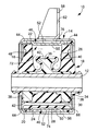
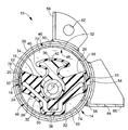
先ず、図1及び図2には、本発明の一実施例としてのエンジンマウント10が示されている。このエンジンマウント10は、パワーユニットと車体の各何れか一方に取り付けられる内筒金具12と円筒状ブラケット14が、互いに径方向に所定距離を隔てて配されて本体ゴム弾性体16によって弾性的に連結されており、パワーユニットを車体に対して防振支持せしめるようになっている。なお、本実施例のエンジンマウント10は、車両への装着状態下、パワーユニット荷重が及ぼされて本体ゴム弾性体16が弾性変形することにより、内筒金具12と円筒状ブラケット14が略同一軸心上に位置せしめられるように、車両への装着前では、内筒金具12が円筒状ブラケット14に対して所定量だけ偏心位置せしめられている。また、本実施例のエンジンマウント10において、防振すべき主たる振動荷重は、内筒金具12と円筒状ブラケット14の略偏心方向(図1,2中、上下方向)に入力されることとなる。
【0017】
より詳細には、内筒金具12や本体ゴム弾性体16は、マウント本体18として一体加硫成形されており、円筒状ブラケット14と別形成された後、円筒状ブラケット14に組み付けられている。かかるマウント本体18は、軸部材としての小径円筒形状の内筒金具12と、該内筒金具12の径方向外方に所定距離を隔てて配設された中間筒部材としての大径円筒形状の金属スリーブ20とが、それらの間に介装された全体として略厚肉円筒形状の本体ゴム弾性体16によって弾性的に連結された構造とされている。即ち、マウント本体18は、本体ゴム弾性体16の内外周面に内筒金具12と金属スリーブ20がそれぞれ加硫接着された一体加硫成形品にて構成されているのである。
【0018】
また、金属スリーブ20には、内外に嵌通する第一の窓部22と第二の窓部24が、内筒金具12に対する偏心方向となる径方向一方向に対向位置して設けられている一方、本体ゴム弾性体16には、外周面上に開口する第一のポケット部26と第二のポケット部28が、径方向一方向に対向位置して設けられており、第一のポケット部26が第一の窓部22を通じて、第二のポケット部28が第二の窓部24を通じて、それぞれ、金属スリーブ20の外周面上に開口せしめられている。更に、本体ゴム弾性体16には、第二のポケット部28の底面に沿って内筒金具12の周りを略半周に亘って延びるスリット30が、軸方向に貫通して設けられており、このスリット30によって、第二のポケット部28の底壁が薄肉とされて弾性変形の容易な可撓性膜32とされている。
【0019】
更にまた、金属スリーブ20の軸方向中央部分には、第一の窓部22と第二の窓部24の周方向両側端縁部間をそれぞれ周方向に延びる凹溝33,33が形成されており、これらの凹溝33,33によって、第一のポケット部26と第二のポケット部28が相互に接続されている。
【0020】
また、内筒金具12には、合成樹脂等の硬質材にて形成されたストッパブロック34が外周面に固着されており、このストッパブロック34によって、第一のポケット部26の底部中央から第一のポケット部26内に突出位置せしめられた、突出先端部が傘状乃至はきのこ状に広がった作用突部36と、第二のポケット部28側に突出せしめられて、金属スリーブ20における第二の窓部24の軸方向両側周縁部に対して、スリット30を挟んで対向位置せしめられた一対のストッパ突部38,38が、一体的に形成されている。そして、作用突部36の突出先端部によって第一のポケット部26内が狭窄されて環状の狭窄部40が形成されている一方、ストッパ突部38,38の金属スリーブ20への当接によって、主たる振動入力方向における内筒金具12と金属スリーブ20の相対的変位量が制限されるようになっている。なお、作用突部36およびストッパ突部38,38の表面は、緩衝ゴム層42によって覆われている。
【0021】
さらに、金属スリーブ20の軸方向両端部には、それぞれ、薄肉のシールゴム44が、周方向全周に亘って連続して形成されて加硫接着されている。このシールゴム44は、金属スリーブ20の軸方向両端部において、該金属スリーブ20の軸方向端部の外周側角部から外周面側と軸方向端面側の両方に延び出して形成されており、それによって、金属スリーブ20の軸方向両端部の外周面から外周側角部を経て軸方向端面にまで至る部分が、シールゴム44によって周方向に連続して覆われている。
【0022】
また、このようなマウント本体18には、それぞれ略半円筒形状を有する一対の半割金具46,46が組み合わされることによって構成された、全体として略円筒形状を有する補強部材48が、外周面上に組み付けられている。かかる半割金具46は、何れも、金属スリーブ20における第一の窓部22および第二の窓部24よりも大きな周方向長さと軸方向長さを有しており、軸方向中央部分が径方向内方に凹陥せしめられて、周方向に連続して延びる幅広の凹陥部50が形成されていると共に、該凹陥部50の外周面上には、周方向に連続して延びる幅広の周溝52が形成されている。なお、半割金具46は、金属板をプレス成形すること等によって、有利に形成され得る。
【0023】
そして、かかる一対の半割金具46,46は、マウント本体18に対して、第一のポケット部26の開口側と、第二のポケット部28の開口側との両方から嵌め合わされることによって、それら第一のポケット部26および第二のポケット部28の開口を覆蓋するようにして配設されている。即ち、各半割金具46は、周方向において金属スリーブ20の凹溝33,33間に跨がって配設されていると共に、軸方向において金属スリーブ20の窓部22,24の軸方向両側縁部間に跨がって配設されており、それによって、各半割金具46が、周方向両側および軸方向両側において、金属スリーブ20によって支持されているのである。
【0024】
なお、一対の半割金具46,46がマウント本体18に組み付けられることにより、両半割金具46,46の周溝52,52が、周方向一方の突合せ部位において相互に連通される一方、周方向他方の突合せ部位において仕切ゴム54で仕切られることにより、全体として周方向に一周弱の長さとされていると共に、仕切ゴム54で仕切られた周方向の両端部において、周溝52の底壁部に貫設された連通孔55により、第一のポケット部26および第二のポケット部28の各一方に連通せしめられている。
【0025】
また、一対の半割金具46は、図1に示されているように、凹陥部50の幅寸法が、第一又は第二のポケット部26,28の軸方向開口幅寸法と略同一とされており、凹陥部50がポケット部26,28の開口部に嵌まり込むことによって、該凹陥部50の軸方向両側面が、ポケット部26,28の開口部における軸方向対向内面に対して、それぞれ密接せしめられている。なお、かかる凹陥部50のポケット部26,28に対する嵌まり込み量(ポケット部26,28内への突出高さ)は、該凹陥部50が金属スリーブ20の内周面よりも径方向内方にまで突出し得るように、金属スリーブ20の肉厚よりも大きく設定することが望ましい。即ち、それによって、金属スリーブ20における第一及び第二の窓部22,24において、ポケット部26,28によって形成された軸方向に延びる空間が、凹陥部50によって閉塞されているのであり、以て、金属スリーブ20において、その第一及び第二の窓部22,24の軸方向両側周縁部が互いに接近せしめられる方向の変形に対して、半割金具46の凹陥部50による抵抗力が発揮されるようになっているのである。なお、このことから明らかなように、本実施例では、凹陥部50によって、ポケット部26,28の開口部に嵌まり込む嵌入部が構成されている。
【0026】
そして、かくの如き補強部材48が組み付けられたマウント本体18に対して、更に、円筒状ブラケット14が外挿され、金属スリーブ20に対して固定的に取り付けられている。かかる円筒状ブラケット14は、鉄やアルミニウム合金等の金属材料によりプレス成形や鋳造等で形成されており、大径円筒形状の筒状部56と、該筒状部56の外周面から径方向外方に突出する取付部としての取付用脚部58,60を、一体的に有している。なお、本実施例では、取付用脚部58,60は、筒状部56と別途形成したものを、筒状部56の外周面に対して溶着すること等によって、筒状部56と一体化されている。また、取付用脚部58,60には、取付用孔62,64が設けられており、これらの取付用孔62,64に挿通されるボルト等によって、取付用脚部58,60が車体側またはパワーユニット側に取り付けられるようになっている。
【0027】
また、筒状部56は、マウント本体18を構成する金属スリーブ20よりも僅かに長い軸方向長さを有していると共に、マウント本体18を構成する金属スリーブ20の外径寸法よりも大きい内径寸法とされており、好ましくは、かかる筒状部56の内径寸法が、マウント本体18に組み付けられた補強部材48の外径寸法よりも僅かに大きく、且つ金属スリーブ20の外周面に形成されたシールゴム44の外径寸法よりも僅かに小さく設定される。なお、補強部材48を構成する一対の半割金具46,46は、周方向一方の突合せ部間に介在せしめられた仕切ゴム54の弾性変形に基づいて縮径方向(互いに接近する方向)に変位可能とされており、それによって、筒状部56の内径寸法が補強部材48の外径寸法と略同一であっても、筒状部56の外挿が容易とされている。
【0028】
更にまた、筒状部56の軸方向一方の開口部には、周方向に連続して径方向内方に突出する内フランジ部66が、一体形成されている。なお、本実施例では、内フランジ部66が、筒状部56の周壁面から略直角に突出して形成されている。
【0029】
また一方、筒状部56の軸方向他方の開口部には、軸方向外方に向かって延び出す円筒形状のかしめ部68が、一体形成されている。このかしめ部68は、筒状部56の端縁部から軸方向外方に行くに従って外径寸法が次第に小さくなるテーパ状外周面70を有しており、径方向の肉厚寸法が突出先端側に向かって次第に小さくされている。なお、かしめ部68の内径寸法は、軸方向全長に亘って、筒状部56の内径寸法と略同一とされている。
【0030】
そして、かくの如き円筒状ブラケット14の筒状部56に対して、そのかしめ部68側の開口部からマウント本体18を内挿せしめた後、該かしめ部68をかしめ加工して径方向内方に屈曲させることによって、図1に示されているように、マウント本体18が円筒状ブラケット14に対して固定的に組み付けられているのである。
【0031】
すなわち、円筒状ブラケット14の筒状部56に内挿されたマウント本体18は、金属スリーブ20の軸方向一端面が、シールゴム44を介して、筒状部56に一体形成された内フランジ部66に当接せしめられて位置決めされているのであり、かかる状態下で、筒状部56に一体形成されたかしめ部68を径方向内方に屈曲させることによって、該かしめ部68が、金属スリーブ20の軸方向他端部に対し、シールゴム44を介して軸方向に押圧するようにして当接,係止されることとなり、以て、それら内フランジ部66とかしめ部68によって、金属スリーブ20が軸方向両側から挟圧保持されて筒状部56に対して固定的に装着されているのである。
【0032】
また、マウント本体18に組み付けられた補強部材48は、軸方向両側端縁部において、それぞれ、金属スリーブ20と円筒状ブラケット14の筒状部56との間で挟まれて、ガタツキがない程度に固定的に支持されている。特に本実施例では、補強部材48を挟持する金属スリーブ20の外周面上に弾性変形が認められる程のゴム層が形成されておらず、補強部材48が、金属スリーブ20と筒状部56の間で、実質的に直接に挟まれて支持されている。
【0033】
さらに、マウント本体18が円筒状ブラケット14に組み付けられることによって、補強部材48によって閉塞された第一及び第二のポケット部26,28の開口が、円筒状ブラケット14の筒状部56によって流体密に覆蓋されると共に、補強部材48に形成された周溝52,52が、円筒状ブラケット14の筒状部56によって流体密に覆蓋されており、以て、第一のポケット部26によって受圧室72が、第二のポケット部28によって平衡室74が、それぞれ形成されていると共に、周溝52,52によって、それら受圧室72と平衡室74を連通するオリフィス通路76が協働して形成されている。
【0034】
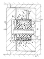
また、本実施例では、図3に示されているように、マウント本体18の筒状部56への内挿とかしめ加工による固定が、所定の非圧縮性流体78中で行われ、それによって、マウント本体18の円筒状ブラケット14への組付けと同時に、受圧室72,平衡室74およびオリフィス通路76に、非圧縮性流体が封入されている。なお、円筒状ブラケット14のかしめ部68を金属スリーブ20の軸方向端部に係止せしめるかしめ加工は、例えば、図示されているように、マウント本体18が組み付けられた円筒状ブラケット14を、支持治具80によって、内フランジ部66側の軸方向端面において支持せしめた状態下、テーパ状内周面82を有するかしめ治具84を、案内治具86に沿って移動せしめて、円筒状ブラケット14の筒状部56におけるかしめ部68の軸方向端部外周面に当接させて軸方向に押圧すること等による、従来から公知の一般的な手法に従って行われ得る。
【0035】
このような構造とされたエンジンマウント10においては、内筒金具12と円筒状ブラケット14の間に振動が入力された際、受圧室72と平衡室74の間に惹起される相対的な内圧変動に基づいて、それら両室72,74間でオリフィス通路76を通じての流体流動が生ぜしめられて、かかる流体の共振作用等の流動作用に基づいて、低動ばね効果や減衰効果等の所定の防振効果が発揮されるようになっているのである。また、本実施例のエンジンマウント10では、作用突部36によって受圧室72内に形成された狭窄部40を通じて流動せしめられる流体の流動作用に基づく防振効果も、発揮されるようになっている。なお、封入流体としては、特に限定されるものでないが、本実施例では、流体の共振作用に基づく防振効果を有効に得るために、0.1Pa・s以下の低粘性流体、例えば水やアルキレングリコール,ポリアルキレングリコール,シリコーン油等が好適に採用される。
【0036】
また、上述の如き構造とされたエンジンマウント10においては、円筒状ブラケット14の筒状部56に形成されたかしめ部68は、シールゴム44を介して、金属スリーブ20の軸方向端部の外周側角部に圧接されており、それによって、金属スリーブ20の筒状部56からの抜け抗力(耐軸方向荷重性能)が確保されていると共に、それらかしめ部68と金属スリーブ20の圧接部間でシールゴム44が挟圧されて流体密性が確保されている。要するに、上述の如き構造とされたエンジンマウント10においては、金属スリーブ20の軸方向両端面にまでシールゴム44が回されており、円筒状ブラケット14における筒状部56の内フランジ部66とかしめ部68の間で軸方向に挟圧されることによって、金属スリーブ20の軸方向両端部分において、金属スリーブ20と筒状部56の間が流体密にシールされているのであり、以て、封入流体のシール性が確保されるようになっているのである。
【0037】
しかも、かかるエンジンマウント10においては、金属スリーブ20における軸方向の荷重強度乃至は変形強度が、窓部22,24の形成部位においても、ポケット部26,28の開口部に嵌め込まれて、該開口部における軸方向対向内面に密接された補強部材48の凹陥部50によって、有利に確保されているところから、円筒状ブラケット14を金属スリーブ20にかしめ固定するに際して、金属スリーブ20に対する軸方向の押圧力が及ぼされた場合でも、金属スリーブ20における変形が効果的に軽減乃至は防止され得るのであり、それ故、金属スリーブ20の変形に起因する流体密性や防振性能の低下が効果的に回避され得るのである。
【0038】
加えて、かかるエンジンマウント10においては、金属スリーブ20における軸方向の荷重強度乃至は変形強度を確保するための補強部材48を利用して、マウント外周部分を周方向に延びるオリフィス通路76が形成されているのであり、換言すれば、マウント外周部分にオリフィス通路76を形成するためのオリフィス形成部材を利用して、金属スリーブ20における軸方向の荷重強度乃至は変形強度を確保するための補強部材48が構成されているところから、金属スリーブ10における軸方向の強度向上と、大きな流路長さと断面積を容易に得ることの出来るオリフィス通路の形成とが、優れた部材活用性とスペース効率をもって、簡単な構造により達成され得るのである。
【0039】
以上、本発明の実施例について詳述してきたが、これは文字通りの例示であって、本発明は、かかる具体例にのみ限定して解釈されるものではない。
【0040】
例えば、流体室の構造や封入流体の種類、本体ゴム弾性体の形状等といったマウント本体の構造は、要求されるマウント特性に応じて適宜に決定されるものであって限定されるものでなく、三つ以上の流体室を形成したり、或いは減衰効果を得るために高粘性流体を封入すること等も可能である。
【0041】
また、中間筒部材や筒状ブラケットの具体的形状は、何等限定されるものでなく、例示の如き円筒形状のものの他、各筒形状のもの等を採用することも可能であり、また、筒状ブラケットにおける取付部は、マウントが取り付けられるべき部材等に応じて各種の形状が採用され得る。
【0042】
さらに、オリフィス通路の形状も、要求されるマウント特性等に応じて適宜に決定されるものであり、例えば、蛇行して周方向に延びるオリフィス通路や周方向に一周以上の長さで螺旋状に延びるオリフィス通路等を採用することも可能である。
【0043】
また、中間筒部材に筒状ブラケットを組み付けた後に、本体ゴム弾性体に刺針して非圧縮性流体を注入したり、円筒状ブラケット14に貫設された注入孔を通じて非圧縮性流体を注入した後にブラインドリベット等で該注入孔を封止すること等によって、流体室に非圧縮性流体を充填することも可能であり、また、非圧縮性流体中において中間筒部材に筒状ブラケットを外挿せしめた後、非圧縮性流体中から取り出して、筒状ブラケットの中間筒部材に対する係止加工を大気中で行うことも可能である。
【0044】
更にまた、前記実施例では、流体室を形成する凹所が、何れも、本体ゴム弾性体に設けられたポケット部によって構成されていたが、そのうちの幾つかを、実開平2−94952号公報等に記載されているように、中間筒部材の一部を凹陥せしめて形成した、中間筒部材の外周面に開口する凹陥部等によって構成することも可能である。
【0045】
加えて、本実施例では、エンジンマウントに本発明を適用したものの具体例を示したが、本発明は、ボデーマウントやデフマウント、或いは自動車以外の各種の流体封入式筒型マウント装置に対しても、有利に適用され得ることは、言うまでもない。
【0046】
その他、一々列挙はしないが、本発明は、当業者の知識に基づいて、種々なる変更,修正,改良等を加えた態様において実施され得るものであり、また、そのような実施態様が、本発明の趣旨を逸脱しない限り、何れも、本発明の範囲内に含まれるものであることは、言うまでもないところである。
【0047】
【発明の効果】
上述の説明から明らかなように、本発明に従う構造とされた流体封入式筒型マウント装置においては、筒状ブラケットが中間筒部材に対して直接に固着されることから、従来構造における外筒金具が廃止されて部品点数の削減と軽量化および製作性の向上等が達成され得るのであり、しかも、中間筒部材の窓部に補強部材の嵌入部が嵌め込まれることによって、中間筒部材の軸方向強度が確保されており、筒状ブラケットの係止に際しての中間筒部材の変形が防止されることから、安定した流体密性と目的とする防振性能を、共に有利に得ることが出来るのである。
【0048】
また、本発明に従う構造とされた流体封入式筒型マウント装置においては、中間筒部材を補強する補強部材を利用して、マウント外周部分を周方向に延びるオリフィス通路が形成されていることから、部材を有効に活用して、オリフィス通路を形成することが出来るのである。
【図面の簡単な説明】
【図1】本発明の実施例としてのエンジンマウントを示す縦断面図である。
【図2】図1に示されたエンジンマウントの横断面図である。
【図3】図1に示されたエンジンマウントの製作工程を説明するための説明図である。
【符号の説明】
10 エンジンマウント
12 内筒金具
14 円筒状ブラケット
16 本体ゴム弾性体
20 金属スリーブ
22 第一の窓部
24 第二の窓部
26 第一のポケット部
28 第二のポケット部
48 補強部材
50 凹陥部
52 周溝
56 筒状部
58,60 取付用脚部
66 内フランジ部
68 かしめ部
72 受圧室
74 平衡室
76 オリフィス通路[0001]
【Technical field】
The present invention relates to a fluid-filled cylindrical mount device that uses a vibration-proofing effect based on the flow action of a fluid sealed inside, and can exhibit a particularly effective vibration-proofing effect against input vibration in a direction perpendicular to the axis. The present invention relates to a fluid-filled cylindrical mount device.
[0002]
[Prior art]
As a type of vibration isolator interposed between the members to be vibration-isolated, as described in Japanese Patent Application Laid-Open No. 61-270533, Japanese Utility Model Laid-Open No. 2-94952, etc. The shaft bracket and the intermediate tube bracket arranged at a predetermined distance are connected by a main rubber elastic body interposed therebetween, and the outer periphery is formed on the main rubber elastic body through the window portion of the intermediate cylinder bracket. Provided with a plurality of recesses opened on the outer peripheral surface of the intermediate cylinder fitting, including at least one pocket portion opened on the surface, and further, the outer cylinder fitting is extrapolated to the intermediate cylinder fitting and reduced by eight-way drawing or the like A plurality of recesses are fluid-tightly covered and fixed to the intermediate cylindrical fitting by fitting and fixed to the intermediate cylinder fitting, thereby forming a plurality of fluid chambers in which a predetermined incompressible fluid is sealed. An orifice passage that allows communication Comprising mounting device are known structures, since excellent vibration damping effect based on flow action of the fluid flowing through the orifice passage can be exhibited, it is used as an automotive engine mount or the like. In addition, in such a cylindrical mounting device, in general, the shaft bracket is directly attached to one member to be vibration-proof connected with a bolt or the like, while the cylindrical bracket is press-fitted and fixed to the outer cylinder bracket, The outer cylinder fitting is attached to the other member to be vibration-proof connected via the cylindrical bracket.
[0003]
By the way, in recent years, there has been a demand for a structure and a manufacturing process that are simplified by reducing the number of parts, cost reduction, and the like. It is conceivable to eliminate the outer tube metal fitting by externally fixing the fluid tightly.
[0004]
However, in general, a mounting portion for fixing to a member to be vibration-proof connected to the cylindrical bracket protrudes on the outer peripheral surface, and it is extremely difficult to reduce the diameter such as an eight-way drawing. There is a problem that the fixing force of the cylindrical bracket to the intermediate cylinder fitting is insufficient, or the sealing property between the cylindrical bracket and the intermediate cylinder fitting is insufficient, and the fluid tightness of the fluid chamber tends to be insufficient.
[0005]
Although it is conceivable that the cylindrical bracket is directly press-fitted and fixed to the intermediate cylinder fitting, a seal rubber is interposed between the cylindrical bracket and the intermediate cylinder fitting to ensure fluid tightness of the fluid chamber. Since it is necessary to squeeze, such a seal rubber is easily damaged by press-fitting and is not realistic.
[0006]
In addition, after the cylindrical bracket is externally attached to the intermediate cylindrical fitting, both axial ends of the cylindrical bracket are locked to both axial ends of the intermediate cylindrical fitting by caulking, etc. It is also conceivable to fix the cylindrical fitting so as to be clamped in the axial direction. However, as described above, since the window portion in which the pocket portion for forming the fluid chamber is opened is formed with a relatively large opening area in the intermediate tube fitting, the cylindrical bracket is attached to the intermediate tube by caulking or the like. The axial pressing force exerted on the intermediate cylindrical fitting when pressed against the axial end of the fitting causes deformation and breakage, particularly on the peripheral edge of the window, thereby providing fluid tightness and vibration-proof characteristics. Is not effective.
[0007]
[Solution]
Here, the present invention has been made in the background as described above, and the problem to be solved is that the cylindrical bracket provided with the mounting portion is provided integrally with the intermediate cylindrical member. A fluid-filled cylindrical mounting device with an improved structure that can eliminate the outer cylindrical metal fitting in the conventional structure while securing good fluid tightness and vibration isolation characteristics by directly fitting and fixing It is to provide.
[0008]
Further, the present invention is a fluid-filled cylinder in which the length and the cross-sectional area of the orifice passage can be set to be large by efficiently using space and components, and the degree of freedom in designing the orifice passage can be advantageously ensured. It is also an object to provide a mold mounting device.
[0009]
[Solution]
And in order to solve such a problem, the features of the present invention are (a) a shaft member, and (b) arranged at a predetermined distance outward in a direction perpendicular to the axis of the shaft member. An intermediate cylinder member having a window, and (c) is interposed between the shaft member and the intermediate cylinder member to connect the two members, and at least one pocket portion opened on the outer peripheral surface is provided, A main rubber elastic body having the pocket portion opened in the window portion of the intermediate cylinder member; and (d) overlapping the outer peripheral surface of the intermediate cylinder member so as to straddle the window portion in the circumferential direction and the axial direction. A reinforcing member having a fitting portion that is fitted into the opening portion of the pocket portion and is brought into close contact with the inner surface facing the axial direction of the opening portion; and (e) the reinforcing member that is extrapolated to the intermediate cylinder member Hold both side edges of the member in the axial direction with the intermediate tube member And a cylindrical bracket that is fixed to both axial ends of the intermediate cylinder member so as to sandwich the intermediate cylinder member in the axial direction, and (f) the pocket portion provided in the main rubber elastic body. And a plurality of fluid chambers filled with an incompressible fluid formed by covering the openings of the plurality of recesses formed on the outer peripheral surface of the intermediate cylinder member with the reinforcing member. (G) an orifice passage formed between the reinforcing member and the cylindrical bracket and communicating the plurality of fluid chambers; and (h) both axial ends of the intermediate cylinder member Are continuously formed and vulcanized and bonded over the entire circumference in the circumferential direction, and a portion extending from the outer peripheral surface of both ends in the axial direction of the intermediate cylindrical member to the end surface in the axial direction through the corner on the outer peripheral side in the circumferential direction. Both ends in the axial direction of the intermediate cylinder member so as to cover continuously And a sealing rubber which is interposed between axially engaging portions of the cylindrical bracket and seal rubber for fluid-tightly sealing between the intermediate cylindrical member and the locking portion of the cylindrical bracket. In the mold mounting device.
[0010]
In the fluid-filled cylindrical mount device configured as described above, the cylindrical bracket is locked in the axial direction with respect to both axial ends of the intermediate cylindrical member by caulking or the like. Since the cylindrical bracket is fixed to the intermediate cylindrical member, it is not necessary to reduce the diameter of the cylindrical bracket, and the cylindrical bracket can be attached to the intermediate cylindrical member even if the mounting portion protrudes from the outer peripheral surface of the cylindrical bracket. As a result, the outer cylindrical fitting in the conventional structure can be eliminated, and the number of parts can be reduced, the weight can be reduced, and the productivity can be improved.
[0011]
Moreover, since the window portion of the intermediate cylindrical member is reinforced by the insertion portion of the reinforcing member fitted into the opening portion of the pocket portion, the deformation strength in the axial direction is improved. The intermediate cylindrical member is prevented from being deformed by the axial pressing force exerted on the cylindrical member, and the fluid tightness and the vibration-proof performance due to the deformation of the intermediate cylindrical member are avoided, and the stable fluid tightness is avoided. Both the desired anti-vibration performance are advantageously and stably exhibited.
[0012]
In addition, the reinforcing member is also utilized as an orifice forming member that forms an orifice passage between the reinforcing member and the cylindrical bracket, whereby an orifice passage that extends with a sufficient length in the circumferential direction on the outer peripheral portion is obtained. It can be advantageously formed while effectively utilizing the members and space.
[0013]
In addition, the reinforcing member employed in the present invention may be any member that has a rigidity that can exhibit sufficient strength to prevent deformation of the intermediate cylindrical member when the cylindrical bracket is locked, such as iron or aluminum. In addition to those made of a metal material such as an alloy, those made of a synthetic resin material such as fiber reinforced nylon can also be used. Further, the intermediate cylindrical member may be any material as long as it has the load-bearing strength required for the mount, and the material is not particularly limited. However, considering the adhesiveness with the rubber elastic body, the intermediate cylindrical member is made of a metal material such as iron. A thing is suitably employ | adopted.
[0014]
Furthermore, in the present invention, as described in claim 2, both side edges in the axial direction of the reinforcing member are substantially directly sandwiched and supported by the intermediate cylindrical member and the cylindrical bracket. It is desirable. By adopting such a configuration, since the rubber elastic body or the like is not substantially interposed between the support portions of the reinforcing member, the occurrence of rattling due to the settling of the member is prevented and the durability is improved. Can be illustrated.
[0015]
BEST MODE FOR CARRYING OUT THE INVENTION
Hereinafter, in order to clarify the present invention more specifically, embodiments of the present invention will be described in detail with reference to the drawings.
[0016]
First, FIGS. 1 and 2 show an
[0017]
More specifically, the inner cylinder fitting 12 and the main rubber
[0018]
In addition, the
[0019]
Furthermore, in the axially central portion of the
[0020]
In addition, a
[0021]
Further,
[0022]
In addition, the
[0023]
The pair of
[0024]
In addition, by assembling the pair of
[0025]
Further, as shown in FIG. 1, in the pair of half-
[0026]
Further, the
[0027]
The
[0028]
Furthermore, an
[0029]
On the other hand, a
[0030]
And after mounting the mount
[0031]
That is, the mount
[0032]
Further, the reinforcing
[0033]
Further, when the
[0034]
Further, in the present embodiment, as shown in FIG. 3, the mounting
[0035]
In the
[0036]
Further, in the
[0037]
Moreover, in the
[0038]
In addition, in the
[0039]
As mentioned above, although the Example of this invention was explained in full detail, this is a literal illustration, Comprising: This invention is limited to this specific example, and is not interpreted.
[0040]
For example, the structure of the mount body, such as the structure of the fluid chamber, the type of sealed fluid, the shape of the main rubber elastic body, etc., is appropriately determined according to the required mount characteristics, and is not limited. It is possible to form three or more fluid chambers, or to enclose a highly viscous fluid in order to obtain a damping effect.
[0041]
Further, the specific shapes of the intermediate cylindrical member and the cylindrical bracket are not limited at all, and it is possible to adopt cylindrical shapes as well as cylindrical shapes as illustrated, Various shapes can be adopted as the attachment portion of the bracket in accordance with the member to which the mount is to be attached.
[0042]
Furthermore, the shape of the orifice passage is also appropriately determined according to the required mount characteristics and the like, for example, an orifice passage that snakes and extends in the circumferential direction or a spiral shape with a length of one or more rounds in the circumferential direction. An extending orifice passage or the like may be employed.
[0043]
In addition, after the cylindrical bracket is assembled to the intermediate cylindrical member, the main rubber elastic body is pierced to inject the incompressible fluid, or the incompressible fluid is injected through the injection hole penetrating the
[0044]
Furthermore, in the above-described embodiment, all the recesses forming the fluid chamber are constituted by pocket portions provided in the main rubber elastic body, but some of them are disclosed in Japanese Utility Model Laid-Open No. 2-94952. As described in the above, it is also possible to configure by a recessed portion or the like that is formed by recessing a part of the intermediate cylinder member and that opens to the outer peripheral surface of the intermediate cylinder member.
[0045]
In addition, in this embodiment, a specific example of applying the present invention to an engine mount is shown. However, the present invention is applied to a body mount, a differential mount, or various fluid-filled cylindrical mount devices other than automobiles. However, it goes without saying that it can be advantageously applied.
[0046]
In addition, although not listed one by one, the present invention can be implemented in a mode with various changes, corrections, improvements, and the like based on the knowledge of those skilled in the art. It goes without saying that all are included in the scope of the present invention without departing from the spirit of the invention.
[0047]
【The invention's effect】
As is clear from the above description, in the fluid-filled cylindrical mount device having the structure according to the present invention, the cylindrical bracket is directly fixed to the intermediate cylindrical member. Can be reduced, the number of parts can be reduced, the weight can be reduced, the productivity can be improved, and the insertion of the reinforcing member can be fitted into the window of the intermediate cylindrical member, so that the axial direction of the intermediate cylindrical member can be achieved. Since the strength is ensured and the deformation of the intermediate cylindrical member at the time of locking the cylindrical bracket is prevented, both stable fluid tightness and the desired vibration isolation performance can be advantageously obtained. .
[0048]
Further, in the fluid-filled cylindrical mount device structured according to the present invention, an orifice passage is formed extending in the circumferential direction around the outer periphery of the mount using a reinforcing member that reinforces the intermediate cylindrical member. The orifice passage can be formed by effectively utilizing the member.
[Brief description of the drawings]
FIG. 1 is a longitudinal sectional view showing an engine mount as an embodiment of the present invention.
FIG. 2 is a cross-sectional view of the engine mount shown in FIG.
FIG. 3 is an explanatory diagram for explaining a manufacturing process of the engine mount shown in FIG. 1;
[Explanation of symbols]
10 Engine mount
12 Inner tube bracket
14 Cylindrical bracket
16 Body rubber elastic body
20 Metal sleeve
22 First window
24 Second window
26 First pocket
28 Second pocket
48 Reinforcing member
50 depression
52 circumferential groove
56 Cylindrical part
58,60 Mounting legs
66 Inner flange
68 Caulking part
72 Pressure receiving chamber
74 Equilibrium room
76 Orifice passage
Claims (2)
該軸部材の軸直角方向外方に所定距離を隔てて配された、窓部を有する中間筒部材と、
該軸部材と該中間筒部材の間に介装されてそれら両部材を連結すると共に、外周面に開口するポケット部が少なくとも一つ設けられて、該ポケット部が該中間筒部材の前記窓部内に開口せしめられた本体ゴム弾性体と、
前記中間筒部材の外周面に重ね合わされて、前記窓部を周方向および軸方向に跨いで配された、前記ポケット部の開口部に嵌まり込んで該開口部の軸方向対向内面に密接せしめられる嵌入部を有する補強部材と、
前記中間筒部材に外挿されて、前記補強部材の軸方向両側縁部を該中間筒部材との間で挟んで支持せしめると共に、該中間筒部材を軸方向に挟持するようにして該中間筒部材の軸方向両端部に係止固定された筒状ブラケットと、
前記本体ゴム弾性体に設けられた前記ポケット部を含む、前記中間筒部材の外周面に開口して形成された複数の凹所の開口が前記補強部材で覆蓋されることによって形成された、非圧縮性流体が封入された複数の流体室と、
前記補強部材と前記筒状ブラケットの間に形成されて、前記複数の流体室を連通せしめるオリフィス通路と、
前記中間筒部材の軸方向両端部の周方向全周に亘ってそれぞれ連続して形成されて加硫接着され、該中間筒部材の軸方向両端部の外周面から外周側角部を経て軸方向端面にまで至る部分を周方向に連続して覆うように、該中間筒部材の軸方向両端部と前記筒状ブラケットとの軸方向係止部位に介在せしめられて、それら中間筒部材と筒状ブラケットの係止部間を流体密にシールするシールゴムとを、
有することを特徴とする流体封入式筒型マウント装置。A shaft member;
An intermediate cylinder member having a window portion disposed at a predetermined distance outward in a direction perpendicular to the axis of the shaft member;
The shaft member and the intermediate cylindrical member are interposed to connect the two members, and at least one pocket portion opened on the outer peripheral surface is provided, and the pocket portion is provided in the window portion of the intermediate cylindrical member. The body rubber elastic body opened in,
Overlaid on the outer peripheral surface of the intermediate cylindrical member, the window portion is disposed across the circumferential direction and the axial direction, and is fitted into the opening portion of the pocket portion so as to be in close contact with the axially opposed inner surface of the opening portion. A reinforcing member having an inserted portion;
The intermediate cylinder member is extrapolated to the intermediate cylinder member so that both side edges in the axial direction of the reinforcing member are sandwiched between and supported by the intermediate cylinder member, and the intermediate cylinder member is clamped in the axial direction. A cylindrical bracket locked and fixed to both axial ends of the member;
A plurality of recess openings formed on the outer peripheral surface of the intermediate cylinder member, including the pocket portion provided in the main rubber elastic body, are formed by covering with the reinforcing member. A plurality of fluid chambers filled with compressible fluid;
An orifice passage formed between the reinforcing member and the cylindrical bracket to communicate the plurality of fluid chambers;
The intermediate cylinder member is continuously formed and vulcanized and bonded over the entire circumference in the axial direction at both ends in the axial direction, and axially passes from the outer peripheral surface of both ends in the axial direction of the intermediate cylinder member to the outer peripheral side corners. The intermediate cylindrical member and the cylindrical member are interposed between axially opposite ends of the intermediate cylindrical member and the axial bracket portion so as to continuously cover the portion extending to the end surface in the circumferential direction. Seal rubber that seals between the locking parts of the bracket fluidly,
A fluid-filled cylindrical mount device characterized by comprising:
Priority Applications (1)
| Application Number | Priority Date | Filing Date | Title |
|---|---|---|---|
| JP6654496A JP3658843B2 (en) | 1996-03-22 | 1996-03-22 | Fluid-filled cylindrical mounting device |
Applications Claiming Priority (1)
| Application Number | Priority Date | Filing Date | Title |
|---|---|---|---|
| JP6654496A JP3658843B2 (en) | 1996-03-22 | 1996-03-22 | Fluid-filled cylindrical mounting device |
Publications (2)
| Publication Number | Publication Date |
|---|---|
| JPH09257088A JPH09257088A (en) | 1997-09-30 |
| JP3658843B2 true JP3658843B2 (en) | 2005-06-08 |
Family
ID=13318959
Family Applications (1)
| Application Number | Title | Priority Date | Filing Date |
|---|---|---|---|
| JP6654496A Expired - Fee Related JP3658843B2 (en) | 1996-03-22 | 1996-03-22 | Fluid-filled cylindrical mounting device |
Country Status (1)
| Country | Link |
|---|---|
| JP (1) | JP3658843B2 (en) |
-
1996
- 1996-03-22 JP JP6654496A patent/JP3658843B2/en not_active Expired - Fee Related
Also Published As
| Publication number | Publication date |
|---|---|
| JPH09257088A (en) | 1997-09-30 |
Similar Documents
| Publication | Publication Date | Title |
|---|---|---|
| JPH0771513A (en) | High viscousity fluid charged type cylindric mount | |
| JPH08135723A (en) | Fluid sealed cylindrical mount | |
| JPH08177945A (en) | Fluid sealing type cylindrical vibration proof device | |
| JP3788164B2 (en) | Fluid filled mount | |
| JPH028173B2 (en) | ||
| JP5462040B2 (en) | Liquid seal vibration isolator and manufacturing method thereof | |
| EP1118794B1 (en) | Fluid filled cylindrical elastic mount having intermediate sleeve exhibiting improved deformation resistance and method of producing the same | |
| JPH026935B2 (en) | ||
| JP3658843B2 (en) | Fluid-filled cylindrical mounting device | |
| JPH07293627A (en) | Cylindrical vibration isolator | |
| JPH0524837Y2 (en) | ||
| JP3736155B2 (en) | Fluid-filled cylindrical vibration isolator and manufacturing method thereof | |
| JPH0633230Y2 (en) | Fluid filled cushion rubber assembly | |
| JPH1182607A (en) | Fluid sealed tubular mount | |
| JP4073028B2 (en) | Fluid filled cylindrical vibration isolator | |
| JP3777784B2 (en) | Cylindrical fluid-filled mounting device | |
| JP3731412B2 (en) | Fluid-filled vibration isolator and manufacturing method thereof | |
| JP3484848B2 (en) | Fluid-filled cylindrical mount device and method of manufacturing the same | |
| JP3672998B2 (en) | Fluid-filled cylindrical mount and manufacturing method thereof | |
| JPH11210812A (en) | Fluid enclosed type cylindrical mount device and manufacture thereof | |
| JP3633075B2 (en) | Fluid-filled cylindrical mount device and manufacturing method thereof | |
| JPH0524836Y2 (en) | ||
| JP2003184943A (en) | Fluid-sealed vibrationproof equipment | |
| JP2005291447A (en) | Fluid-sealed vibration control connecting rod | |
| JP2001140971A (en) | Fluid sealed vibration control device and manufacturing method for it |
Legal Events
| Date | Code | Title | Description |
|---|---|---|---|
| A977 | Report on retrieval |
Effective date: 20040714 Free format text: JAPANESE INTERMEDIATE CODE: A971007 |
|
| A131 | Notification of reasons for refusal |
Effective date: 20040803 Free format text: JAPANESE INTERMEDIATE CODE: A131 |
|
| A521 | Written amendment |
Effective date: 20040929 Free format text: JAPANESE INTERMEDIATE CODE: A523 |
|
| TRDD | Decision of grant or rejection written | ||
| A01 | Written decision to grant a patent or to grant a registration (utility model) |
Effective date: 20050222 Free format text: JAPANESE INTERMEDIATE CODE: A01 |
|
| A61 | First payment of annual fees (during grant procedure) |
Effective date: 20050307 Free format text: JAPANESE INTERMEDIATE CODE: A61 |
|
| R150 | Certificate of patent (=grant) or registration of utility model |
Free format text: JAPANESE INTERMEDIATE CODE: R150 |
|
| FPAY | Renewal fee payment (prs date is renewal date of database) |
Free format text: PAYMENT UNTIL: 20080325 Year of fee payment: 3 |
|
| FPAY | Renewal fee payment (prs date is renewal date of database) |
Free format text: PAYMENT UNTIL: 20090325 Year of fee payment: 4 |
|
| FPAY | Renewal fee payment (prs date is renewal date of database) |
Year of fee payment: 4 Free format text: PAYMENT UNTIL: 20090325 |
|
| FPAY | Renewal fee payment (prs date is renewal date of database) |
Free format text: PAYMENT UNTIL: 20100325 Year of fee payment: 5 |
|
| LAPS | Cancellation because of no payment of annual fees |