WO2016088718A1 - 電動パワーステアリング装置 - Google Patents
電動パワーステアリング装置 Download PDFInfo
- Publication number
- WO2016088718A1 WO2016088718A1 PCT/JP2015/083617 JP2015083617W WO2016088718A1 WO 2016088718 A1 WO2016088718 A1 WO 2016088718A1 JP 2015083617 W JP2015083617 W JP 2015083617W WO 2016088718 A1 WO2016088718 A1 WO 2016088718A1
- Authority
- WO
- WIPO (PCT)
- Prior art keywords
- steering
- torque
- steering angle
- command value
- electric power
- Prior art date
Links
Images


Classifications
-
- B—PERFORMING OPERATIONS; TRANSPORTING
- B62—LAND VEHICLES FOR TRAVELLING OTHERWISE THAN ON RAILS
- B62D—MOTOR VEHICLES; TRAILERS
- B62D5/00—Power-assisted or power-driven steering
- B62D5/04—Power-assisted or power-driven steering electrical, e.g. using an electric servo-motor connected to, or forming part of, the steering gear
- B62D5/0457—Power-assisted or power-driven steering electrical, e.g. using an electric servo-motor connected to, or forming part of, the steering gear characterised by control features of the drive means as such
- B62D5/046—Controlling the motor
- B62D5/0463—Controlling the motor calculating assisting torque from the motor based on driver input
-
- B—PERFORMING OPERATIONS; TRANSPORTING
- B62—LAND VEHICLES FOR TRAVELLING OTHERWISE THAN ON RAILS
- B62D—MOTOR VEHICLES; TRAILERS
- B62D1/00—Steering controls, i.e. means for initiating a change of direction of the vehicle
- B62D1/24—Steering controls, i.e. means for initiating a change of direction of the vehicle not vehicle-mounted
- B62D1/28—Steering controls, i.e. means for initiating a change of direction of the vehicle not vehicle-mounted non-mechanical, e.g. following a line or other known markers
- B62D1/286—Systems for interrupting non-mechanical steering due to driver intervention
-
- B—PERFORMING OPERATIONS; TRANSPORTING
- B62—LAND VEHICLES FOR TRAVELLING OTHERWISE THAN ON RAILS
- B62D—MOTOR VEHICLES; TRAILERS
- B62D1/00—Steering controls, i.e. means for initiating a change of direction of the vehicle
- B62D1/24—Steering controls, i.e. means for initiating a change of direction of the vehicle not vehicle-mounted
- B62D1/28—Steering controls, i.e. means for initiating a change of direction of the vehicle not vehicle-mounted non-mechanical, e.g. following a line or other known markers
-
- B—PERFORMING OPERATIONS; TRANSPORTING
- B62—LAND VEHICLES FOR TRAVELLING OTHERWISE THAN ON RAILS
- B62D—MOTOR VEHICLES; TRAILERS
- B62D15/00—Steering not otherwise provided for
- B62D15/02—Steering position indicators ; Steering position determination; Steering aids
- B62D15/025—Active steering aids, e.g. helping the driver by actively influencing the steering system after environment evaluation
-
- B—PERFORMING OPERATIONS; TRANSPORTING
- B62—LAND VEHICLES FOR TRAVELLING OTHERWISE THAN ON RAILS
- B62D—MOTOR VEHICLES; TRAILERS
- B62D15/00—Steering not otherwise provided for
- B62D15/02—Steering position indicators ; Steering position determination; Steering aids
- B62D15/027—Parking aids, e.g. instruction means
-
- B—PERFORMING OPERATIONS; TRANSPORTING
- B62—LAND VEHICLES FOR TRAVELLING OTHERWISE THAN ON RAILS
- B62D—MOTOR VEHICLES; TRAILERS
- B62D5/00—Power-assisted or power-driven steering
- B62D5/04—Power-assisted or power-driven steering electrical, e.g. using an electric servo-motor connected to, or forming part of, the steering gear
- B62D5/0457—Power-assisted or power-driven steering electrical, e.g. using an electric servo-motor connected to, or forming part of, the steering gear characterised by control features of the drive means as such
- B62D5/0481—Power-assisted or power-driven steering electrical, e.g. using an electric servo-motor connected to, or forming part of, the steering gear characterised by control features of the drive means as such monitoring the steering system, e.g. failures
- B62D5/0493—Power-assisted or power-driven steering electrical, e.g. using an electric servo-motor connected to, or forming part of, the steering gear characterised by control features of the drive means as such monitoring the steering system, e.g. failures detecting processor errors, e.g. plausibility of steering direction
-
- B—PERFORMING OPERATIONS; TRANSPORTING
- B62—LAND VEHICLES FOR TRAVELLING OTHERWISE THAN ON RAILS
- B62D—MOTOR VEHICLES; TRAILERS
- B62D6/00—Arrangements for automatically controlling steering depending on driving conditions sensed and responded to, e.g. control circuits
- B62D6/007—Arrangements for automatically controlling steering depending on driving conditions sensed and responded to, e.g. control circuits adjustable by the driver, e.g. sport mode
-
- B—PERFORMING OPERATIONS; TRANSPORTING
- B62—LAND VEHICLES FOR TRAVELLING OTHERWISE THAN ON RAILS
- B62D—MOTOR VEHICLES; TRAILERS
- B62D6/00—Arrangements for automatically controlling steering depending on driving conditions sensed and responded to, e.g. control circuits
- B62D6/04—Arrangements for automatically controlling steering depending on driving conditions sensed and responded to, e.g. control circuits responsive only to forces disturbing the intended course of the vehicle, e.g. forces acting transversely to the direction of vehicle travel
-
- B—PERFORMING OPERATIONS; TRANSPORTING
- B62—LAND VEHICLES FOR TRAVELLING OTHERWISE THAN ON RAILS
- B62D—MOTOR VEHICLES; TRAILERS
- B62D6/00—Arrangements for automatically controlling steering depending on driving conditions sensed and responded to, e.g. control circuits
- B62D6/08—Arrangements for automatically controlling steering depending on driving conditions sensed and responded to, e.g. control circuits responsive only to driver input torque
Definitions
- the present invention relates to an electric power steering apparatus having functions of automatic steering control (automatic driving mode, parking assist mode, etc.) and manual steering control, and applying an assist force by a motor to a steering system of a vehicle.
- the control method is switched between a torque control method for controlling the motor output torque and a position / speed control method for controlling the steering angle of the steering, and the steering angle command value and the rudder are controlled according to the steering torque.
- the present invention relates to an electric power steering apparatus capable of changing a fade process (gradual change time, gain) of angular velocity and assist torque level.
- An electric power steering device that includes a motor control device and applies a steering assist force (assist force) to the vehicle steering system by the rotational force of the motor is configured to drive the motor driving force through a reducer, such as a gear or a belt. With this transmission mechanism, a steering assist force is applied to the steering shaft or the rack shaft.
- a conventional electric power steering apparatus performs feedback control of the motor current in order to accurately generate the torque of the steering assist force.
- the motor applied voltage is adjusted so that the difference between the steering assist command value (current command value) and the motor current detection value is small.
- the adjustment of the motor applied voltage is generally performed by PWM (pulse width). This is done by adjusting the duty of modulation) control.
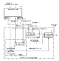
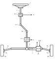
- the column shaft 2 is provided with a torque sensor 10 that detects the steering torque of the handle 1, and a motor 20 that assists the steering force of the handle (steering wheel) 1 is connected to the column shaft 2 via the reduction gear 3. It is connected.
- the control unit (ECU) 30 that controls the electric power steering apparatus is supplied with electric power from the battery 13 and also receives an ignition key signal via the ignition key 11.
- the control unit 30 calculates a steering assist command value of an assist (steering assist) command based on the steering torque Ts detected by the torque sensor 10 and the vehicle speed Vs detected by the vehicle speed sensor 12, and obtains the steering assist command value.
- the current supplied to the motor 20 is controlled by the voltage control value Vref subjected to compensation or the like.
- the rudder angle sensor 14 is not essential and may not be provided, and may be obtained from a rotation sensor connected to the motor 20.
- control unit 30 Controller Area Network
- vehicle speed Vs can also be received from the CAN 40.
- the control unit 30 can be connected to a non-CAN 41 that exchanges communications, analog / digital signals, radio waves, and the like other than the CAN 40.
- control unit 30 is mainly composed of a CPU (including an MPU, MCU, etc.). General functions executed by a program inside the CPU are shown in FIG. The configuration is as shown.
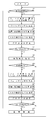
- the function and operation of the control unit 30 will be described with reference to FIG. 2.
- the steering torque Ts from the torque sensor 10 and the vehicle speed Vs from the vehicle speed sensor 12 are input to the current command value calculation unit 31, and the current command value calculation unit 31.
- the calculated current command value Iref1 is added by the adding unit 32A and the compensation signal CM from the compensating unit 34 for improving the characteristics, and the added current command value Iref2 is limited to the maximum value by the current limiting unit 33.
- the current command value Irefm whose maximum value is limited is input to the subtraction unit 32B and subtracted from the motor current detection value Im.
- the motor 20 is PWM driven via the inverter 37 with the PWM signal whose duty is calculated.
- the motor current value Im of the motor 20 is detected by the motor current detection means 38, and is input to the subtraction unit 32B and fed back.
- the compensating unit 34 adds the detected or estimated self-aligning torque (SAT) 34-3 to the inertia compensation value 34-2 by the adding unit 34-4, and further adds the convergence result to the convergence by the adding unit 34-5.
- the control value 34-1 is added, and the addition result is input to the adder 32A as a compensation signal CM to improve the control characteristics.
- automatic steering control is performed in which a target steering angle is set based on data such as a camera (image) and a distance sensor, and the actual steering angle follows the target steering angle.
- the electric power steering device can automatically operate by controlling the position of the actual steering angle so as to follow the steering angle command value.
- back parking is performed by controlling an actuator (motor) based on the relationship between the movement distance of the vehicle stored in advance and the turning angle.
- parallel parking is automatically performed. That is, the automatic steering control device recognizes a parking space from a positioning sensor such as an around view monitor or an ultrasonic sensor, and outputs a steering angle command value to the EPS side.
- the EPS guides the vehicle to the parking space by controlling the position / speed of the actual steering angle and the steering angular speed so as to follow the steering angle command value.
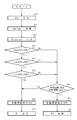
- FIG. 3 shows a control system of an electric power steering apparatus having an automatic steering control function.
- Various data are input to the automatic steering command apparatus 50 from a camera and a positioning sensor (ultrasonic sensor, etc.),
- the angle command value ⁇ tc is input to the position / speed control unit 51 in the EPS actuator function via CAN or the like, and the automatic steering command is input to the automatic steering execution determination unit 52 in the EPS actuator function via CAN or the like.
- a steering torque Ts is also input to the automatic steering execution determination unit 52.
- the actual steering angle ⁇ r and the steering angular velocity ⁇ r from the EPS sensor are input to the position / speed control unit 51, and the determination result of the automatic steering execution determination unit 52 is input to the torque command value gradual change switching unit 54.
- the steering torque Ts of the EPS sensor is input to the torque control unit 53 in the EPS power assist function, and the steering assist torque command value Tc from the torque control unit 53 is input to the torque command value gradual change switching unit 54.
- the position / speed control torque command value Tp from the position / speed control unit 51 is also input to the torque command value gradual change switching unit 54, and the steering assist is performed according to the determination result of the automatic steering execution determination unit 52 (ON / OFF of the automatic steering command).
- the torque command value Tc and the position / speed control torque command value Tp are switched and output as a motor torque command value, and the motor is driven and controlled via the current control system.
- the normal power assist is a torque control system
- it becomes a position / speed control system such as a steering angle.
- the torque control and the position / speed control are switched to each other, there is a problem that the control torque fluctuates, and there is a problem that the switching is not smooth, and a torque fluctuation at the time of switching is a trigger to cause an unintended self-steer.
- the effect cannot be fully exhibited in switching between torque control and position / speed control.
- the cause is that in the case of a system that can input disturbance from the steering wheel, such as electric power steering, the position / speed control assists in the opposite direction when switching to normal power assist control because torque assist is performed to suppress the disturbance. There are cases.
- the present invention has been made under the circumstances as described above, and an object of the present invention is to control torque and position / speed of torque control in response to steering torque in fading processing (gradual change processing) for switching control methods.
- An object of the present invention is to provide an electric power steering apparatus capable of switching a control method smoothly and self-steerlessly by gradually changing a control command value.
- the present invention relates to an electric power steering apparatus having a torque sensor for detecting a steering torque and a motor control apparatus for controlling a motor for applying an assist torque for assisting steering to a steering system of a vehicle.
- the assist torque level of the torque control system is achieved by respectively gradually changing in accordance with the steering torque.
- the above object of the present invention is to provide a fade gain signal F1 that gives a fade characteristic 1 of the torque system according to the steering torque and a fade characteristic 2 of the rudder angle system when the predetermined switching opportunity is turned ON / OFF.
- the position / speed control is performed by the fade gain signal F2 and the characteristic calculation unit for calculating the fade characteristic 3 of the steering angular velocity, or when the switching trigger is turned on, by the fade gain signal F2.
- the steering angle command value is gradually changed from the actual steering angle to the steering angle command value, and the assist torque level is gradually changed from 100% to 0% by the fade gain signal F1.
- F3 the rudder angular speed is gradually changed from 0% to 100%, and it operates by the position / speed control method.
- the fade gain signal F2 is used to gradually change the steering angle command value after the gradual change of the position / speed control from the steering angle command value to the actual steering angle, and the fade gain.
- the assist torque level is gradually changed from 0% to 100%
- the steering angular speed is gradually changed from 100% to 0%
- the torque control system is operated.
- the fade gain signals F1, F2, and F3 are calculated in the form of A ⁇ FG (z ⁇ 1 ) + FR, where the past value of the fade gain is FG (z ⁇ 1 ), the exponential gain is A, and the fade rate is FR.
- the automatic steering execution determination unit inputs the steering angle command value and the angular velocity Diagnosis based on the determination result of the calculation unit that calculates the angular acceleration, the map determination unit that determines the steering angle command value, the angular velocity, and the angular acceleration based on the determination map corresponding to the vehicle speed, respectively.
- a disturbance observer that compensates for inertia and friction of the steering wheel, or the disturbance observer is an LPF that performs band limiting with the inverse model of the steering system.
- the steering angle command value after gradual change is gradually changed from the actual steering angle to the steering angle command value, and the actual steering angle is the steering angle command value and the steering angular speed after the gradual change. Since the position control and the speed control are performed so as to follow the torque, the torque command value of the position / speed control can be automatically and smoothly changed, which is a gentle feeling for the driver. In addition, during the fade process of switching from automatic steering to torque control, even if excessive torque fluctuations occur, the steering angle command value and the steering angular speed are gradually changed in response to the steering torque. Position / speed control automatically compensates for power assist. Thereby, the malfunction that a driver
- the automatic steering operation (position / speed control) respecting the driver's intention and the normal steering by the torque control can be performed with a smooth operation.
- the automatic driving can be quickly interrupted to switch to normal torque control. The effect can be further improved by installing a disturbance observer.
- summary of an electric power steering apparatus (column system). It is a block diagram which shows the structural example of the control system of an electric power steering apparatus. It is a block diagram which shows the structural example of the control system of the electric power steering apparatus which has a parking assistance mode (automatic steering) function. It is a characteristic view which shows the operation
- the conventional torque gradual change control in the electric power steering apparatus has a problem that when the torque control and the position / speed control are switched to each other, there is a problem that the control is not switched smoothly and an unintended self-steer occurs. Therefore, in the present invention, the control torque (assist torque level) for torque control and the command value (steering angle command value, steering angle speed) for position / speed control are gradually changed (fade processing) in accordance with the steering torque. Smooth, self-steerless, control switching is realized.
- the motor control method is switched between a torque control method for controlling the motor output torque and a position / speed control method for controlling the steering angle in accordance with a predetermined switching opportunity (for example, an automatic steering command). It has a function, and the fade process (gradual change time, gain) can be varied according to the steering torque to realize a smooth and self-steerless fade process.
- the present invention includes a single pinion system whose schematic configuration is shown in FIG. 5, a dual pinion system whose schematic is shown in FIG. 6, a dual pinion system (modified example) whose schematic configuration is shown in FIG.
- the present invention can be applied to the rack coaxial system schematically shown in FIG. 8 and the rack offset system schematically shown in FIG. 9, the column system will be described below.
- FIG. 10 shows a configuration example of the present invention, in which the steering torque Ts is input to the torque control unit 102 and is also input as a variable parameter to the automatic steering execution determination unit 120 and the characteristic calculation unit 140, from the torque control unit 102.
- the steering assist torque command value Tc is input to the torque gradual change portion 103 of the torque system.
- the steering angle command value ⁇ tc from CAN or the like is input to the automatic steering execution determination unit 120, and the steering angle command value ⁇ t after the arithmetic processing in the automatic steering execution determination unit 120 is the gradual steering angle command value of the steering angle system.
- the actual steering angle ⁇ r and the actual steering angle ⁇ r are input.
- the automatic steering execution determination unit 120 further outputs ON / OFF of an automatic steering command as a determination result.
- the ON / OFF of the automatic steering command is a torque gradual change unit 103, a steering angle command value gradual change unit 100, a steering angular velocity. This is input to the gradual change unit 105 and the characteristic calculation unit 140.
- the actual steering angle ⁇ r is input to the steering angle command value gradual change unit 100 and the position / speed control unit 101, and the steering angular velocity ⁇ r is input to the steering angular velocity gradual change unit 105.
- the steering angle command value ⁇ m after gradual change from the steering angle command value gradual change unit 100 and the steering angular velocity ⁇ m after gradual change from the steering angular velocity gradual change unit 105 are input to the position / speed control unit 101.
- the torque system fade gain signal F1 calculated by the characteristic calculation unit 140 is input to the torque gradual change unit 103, and the steering angle system fade gain signal F2 is the steering angle command value gradual change unit.
- the steering angular velocity system fade gain signal F ⁇ b> 3 is input to the steering angular velocity gradual change unit 105.
- the steering assist torque command value Tg after the gradual change of torque in the torque gradual change unit 103 is input to the addition unit 104, and the position / speed control torque command value Tp from the position / speed control unit 101 is also input to the addition unit 104 for addition.
- the addition result of the unit 104 is output as a motor torque command value.
- the motor torque command value is input to the current control system 130, and the motor 131 is driven and controlled via the current control system 130.
- a fade gain signal F1 for gradually changing torque a steering angle command
- a fade gain signal F2 for gradual change of value and a fade gain signal F3 for gradual change of steering angular velocity are calculated, and gradual change (time, gain) corresponding to the steering torque Ts is performed for each element.
- the automatic steering execution determination unit 120 is configured as shown in FIG. 11, the steering angle command value ⁇ tc is input to the calculation unit 121, and the calculation unit 121 is based on the steering angle command value ⁇ tc and the angular velocity ⁇ tc and the angular acceleration ⁇ tc. Is calculated.
- the angular velocity ⁇ tc and the angular acceleration ⁇ tc are input to the map determination unit 122 that is determined using a determination map, and the steering angle command value ⁇ tc and the vehicle speed Vs are also input to the map determination unit 122.
- the map determination unit 122 uses a determination map # 1 for the steering angle command value ⁇ tc having a characteristic A1 or B1 as shown in FIG. 12A and an angular velocity ⁇ tc having a characteristic A2 or B2 as shown in FIG. And a determination map # 3 for the angular acceleration ⁇ tc having the characteristic A3 or B3 as shown in FIG.
- the characteristic of the determination map # 1 with respect to the steering angle command value ⁇ tc is a constant value ⁇ tc 0 up to a low vehicle speed Vs1, and decreases like a characteristic A1 or a characteristic B1 within a range equal to or higher than the vehicle speed Vs1.
- Characteristics of determination map # 2 for angular ⁇ tc is 0 constant value ⁇ to low vehicle speed Vs2, it decreases as characteristic A2 or characteristic B2 in vehicle speed Vs2 above range.
- the characteristic of the determination map # 3 with respect to the angular acceleration ⁇ tc is a constant value ⁇ c 0 until the vehicle speed Vs3 at a low speed, and decreases like a characteristic A3 or a characteristic B3 in a range equal to or higher than the vehicle speed Vs3.
- the characteristics of the determination maps # 1 to # 3 are all tunable and may be characteristics that decrease linearly.
- the map determination unit 122 determines whether or not the steering angle command value ⁇ tc exceeds the characteristic value range of the determination map # 1, determines whether or not the angular velocity ⁇ tc exceeds the characteristic value range of the determination map # 2, Further, it is determined whether or not the angular acceleration ⁇ tc exceeds the characteristic value range of the determination map # 3.
- the determination result MD is input to the diagnosis unit 123, and the diagnosis unit 123 outputs ON / OFF of the automatic steering command based on the result of the diagnosis based on time and the number of times, and ON / OFF of the automatic steering command is input to the output unit 124. Is done.
- the output unit 124 outputs the steering angle command value ⁇ t only when the automatic steering command is ON.
- the steering angle command value ⁇ t is input to the steering angle command value gradual change unit 100 together with the actual steering angle ⁇ r.
- the actual steering angle ⁇ r is calculated as follows.
- a sensor as shown in FIG. 13 is mounted on the column shaft 2 (2A (input side), 2B (output side)), and the steering angle is detected. That is, a Hall IC sensor 21 as an angle sensor and a 20 ° rotor sensor 22 as a torque sensor input side rotor are mounted on the input shaft 2A on the handle 1 side of the column shaft 2.
- the Hall IC sensor 21 outputs an AS_IS angle ⁇ h with a cycle of 296 °.
- the 20 ° rotor sensor 22 mounted on the handle 1 side of the torsion bar 23 outputs a column input side angle ⁇ s with a cycle of 20 °, and the column input side angle ⁇ s is input to the steering angle calculation unit 132.
- the output shaft 2B of the column shaft 2 is fitted with a 40 ° rotor sensor 24 of the torque sensor output side rotor, and the column output side angle ⁇ o is output from the 40 ° rotor sensor 24, and the column output side angle ⁇ o is It is input to the steering angle calculation unit 132.
- Both the column input side angle ⁇ s and the column output side angle signal ⁇ o are calculated into absolute angles by the steering angle calculation unit 132, and the column angle on the column input side and the steering angle ⁇ r1 on the column output side of the absolute angle are calculated from the steering angle calculation unit 132. Is output.
- the steering angle ⁇ r on the column input side is described as the actual steering angle, but the steering angle ⁇ r1 on the column output side can also be used as the actual steering angle.
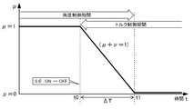
- step S1 When the automatic steering command is not turned on (step S1), normal steering with an assist torque level of 100%, that is, torque control is performed (step S17). Then, when the automatic steering command is turned ON at time t2 by the automatic steering execution determination unit 120 (step S1), the fade process 1 of EPS is started from this time t2 (step S2). At this time, the characteristic calculation unit 140 calculates fade gain signals F1 to F3 based on the steering torque Ts, the fade gain signal F1 is input to the torque gradual change unit 103, and the fade gain signal F2 changes the steering angle command value gradually. The fade gain signal F3 is input to the unit 100 and the steering angular velocity gradual change unit 105 is input (step S3).
- Fade processing time and fade gain characteristics are set by the fade gain signals F1 to F3, respectively.
- the characteristic calculator 140 calculates the fade gain signal F1 according to the following equation 1, calculates the fade gain signal F2 according to the following equation 2, and calculates the fade gain signal F3 according to the following equation 3.
- F1 A1 ⁇ FG (z ⁇ 1 ) + FR1
- FR1 is a fade rate that determines the rate of fade that changes in the control cycle
- A1 is an exponential gain that determines the slope of the exponent
- FG (z -1 ) Is the past value of the fade gain.
- FR3 is a fade rate that determines the rate of fade that changes in the control cycle
- A3 is an exponential gain that determines the slope of the exponent
- FG (z ⁇ 1 ) Is the past value of the fade gain.
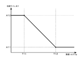
- Equations 1 to 3 when the exponential gains A1 to A3 are set to “1.0”, the fade characteristics are all linear. Further, by varying the exponential gains A1, A2, and A3 according to the steering torque Ts, the fade processing time and gain are controlled. In the fade process from time t2 to time t4, the exponential gain A1 is related to torque gradual change.
- the exponential gain A1 is a constant value A12 up to a predetermined value T11 of the steering torque Ts, The value gradually decreases to the value A11 ( ⁇ A12) below the value T12 (> T11), and becomes a constant value A11 in a region larger than the predetermined value T12.
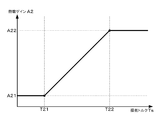
- the exponent gain A2 is related to the gradual change of the steering angle command value.
- the exponent gain A2 is a constant value A21 up to a predetermined value T21 of the steering torque, is equal to or greater than the predetermined value T21, In the following, it gradually increases to the value A22 ( ⁇ a2), and becomes a constant value A22 in a region larger than the predetermined value T22.
- steering torques T11 and T21 and the steering torques T12 and T22 in FIGS. 17 and 18 may be the same value, and the decrease characteristic and the increase characteristic may be non-linear or functions. Furthermore, it may be possible to tune freely according to the hand feeling.
- the steering angle command value gradual change unit 100 gradually changes the steering angle command value ⁇ m after the gradual change of the position / speed control from the actual steering angle ⁇ r to the steering angle command value ⁇ t according to the fade gain signal F2 (step S4). Further, the torque gradual change unit 103 gradually changes the torque level from 100% to 0% in accordance with the fade gain signal F1 (step S5). The steering angular speed gradual change unit 105 gradually changes the steering angular speed ⁇ m after gradual change from 0% to 100% by time t3 in accordance with the fade gain signal F3 (step S6). Thereafter, the above operation is repeated until the end of the fade process 1 (time t4) (step S7).
- the order of position / speed control command value gradual change, torque control level gradual change, and rudder angular speed gradual change in the fade section is arbitrary. Further, the timing chart of FIG. 16 does not show that the fade processing time (time t2 to t4) varies according to the steering torque Ts.
- step S8 From time t4 when the fade process 1 ends, the torque control is switched to automatic steering (position / speed control), and the automatic steering is continued (step S8).
- step S5 when the automatic steering command is turned off by the automatic steering execution determination unit 120 (time t5), or during the automatic steering, the driver steers the steering wheel, the steering torque Ts exceeds a certain threshold, and the automatic steering command is turned off. Then (at time t5), automatic steering ends (step S10), and fade process 2 is started (step S11).
- the characteristic calculation unit 140 calculates the fade gain signals F1 to F3 based on the steering torque Ts according to the equations 1 to 3, and the fade gain signal F2 is input to the steering angle command value gradual change unit 100.
- the fade gain signal F1 is input to the torque gradual change unit 103, and the fade gain signal F3 is input to the steering angular velocity gradual change unit 105 (step S12).
- the steering angle command value gradual change unit 100 gradually changes the steering angle command value ⁇ m after the gradual change of the position / speed control from the steering angle command value ⁇ t to the actual steering angle ⁇ r (step S13), and gradually changes the torque.
- the unit 103 gradually changes the torque level from 0% to 100% (step S14), and the steering angular velocity gradual change unit 105 gradually changes the steering angular velocity ⁇ m after gradual change from 100% to 0% (step S15).
- This fade process 2 is continued until time t63 (step S16), and after time t63 when the fade process ends, the automatic steering is switched to the normal steering torque control (step S17).
- the exponent gains A2 and A3 of the fade gain signals F1 and F3 in this case have the characteristics shown in FIG. 18, respectively, and the exponent gain A1 of the fade gain signal F2 has the characteristics shown in FIG.
- the steering angle command value fade characteristic for position / speed control is an exponential curve, and the gradual change of torque for torque control is a straight line (linear), but it may be a non-linear characteristic or a functional characteristic. It can also be tuned freely according to. The same applies to the gradual change of the rudder angular velocity. Further, the time between time t3 and time t4 in FIG. 16 is an automatic steering section, which indicates that the deviation is zero.
- An example of the operation of the automatic steering execution determination unit 120 is as shown in the flowchart of FIG. 15, and the calculation unit 121 in the automatic steering execution determination unit 120 inputs the steering angle command value ⁇ tc from CAN or the like (step S20). Based on the angle command value ⁇ tc, the angular velocity ⁇ tc and the angular acceleration ⁇ tc are calculated (step S21). The angular velocity ⁇ tc and the angular acceleration ⁇ tc are input to the map determining unit 122, the vehicle speed Vs is also input to the map determining unit 122 (step S22), and the map determining unit 122 first displays the steering angle command value ⁇ tc corresponding to the vehicle speed Vs.
- step S23 It is determined whether it is within the characteristic value range of the determination map # 1 shown in FIG. 12 (A), that is, below the characteristic line of FIG. 12 (A) (step S23), and the characteristic value range of the determination map # 1 If it is within the range, is the angular velocity ⁇ tc corresponding to the vehicle speed Vs next within the characteristic value range of the determination map # 2 shown in FIG. 12B, that is, below the characteristic line in FIG. It is determined whether or not (step S24). If it is within the characteristic value range of the determination map # 2, the angular acceleration ⁇ tc is next within the characteristic value range of the determination map # 3 shown in FIG. 12C corresponding to the vehicle speed Vs, that is, FIG. ) Is determined below the characteristic line (step S25).
- the automatic steering execution determination unit 120 turns on the automatic steering command (step S31), outputs the steering angle command value ⁇ tc as the steering angle command value ⁇ t, and gradually decreases the steering angle command value. Input to the transformation unit 100 (step S32).
- step S23 when the steering angle command value ⁇ tc is not within the characteristic value range of the determination map # 1 shown in FIG. 12A corresponding to the vehicle speed Vs, in step S24, it corresponds to the vehicle speed Vs.
- the angular velocity ⁇ tc is not within the characteristic value range of the determination map # 2 shown in FIG. 12B, in step S25, the angular acceleration ⁇ tc corresponds to the vehicle speed Vs and the determination map shown in FIG.
- the diagnosis unit 123 compares the number of times out of the range with a predetermined number threshold, or compares the time out of the range with a predetermined time threshold (step) S30).
- step S31 If it is equal to or less than the threshold value, the process proceeds to step S31 and the automatic steering command is turned ON. If the number of times or time exceeds the threshold, the automatic steering command is turned off (step S33), and the steering angle command value ⁇ t is cut off and not output (step S34).
- steps S23 to S25 can be changed as appropriate.
- the fade process is started.
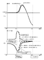
- the gradually changing steering angle command value ⁇ m is gradually changed from the actual steering angle ⁇ r to the steering angle command value ⁇ t. Since the actual steering angle ⁇ r is position / speed controlled so as to follow the steering angle command value ⁇ m after the gradual change, the torque command value of the position / speed control can be automatically and smoothly changed. A gentle hand feeling. Note that FIG. 19B shows that the position deviation appears in the torque.
- the steering angle command value ⁇ m after gradually changing is steered even if excessive steering torque fluctuation occurs after time t21. Since the angle command value ⁇ t is gradually changed from the actual steering angle ⁇ r, the excessive steering torque fluctuation is automatically compensated by the position / speed control. As a result, the driver is prevented from taking the steering wheel. That is, in the present invention, as shown in FIG. 20A, the position / velocity control is performed so that the actual steering angle ⁇ r follows the steering angle command value ⁇ m after the gradual change, so that the generation of the peak is delayed.
- a position / speed control torque command value Tp is generated according to the difference between the steering angle command value ⁇ m and the actual steering angle ⁇ r, and smoothly converges.
- the conventional control as shown by the broken line in FIG. 20A, since the gradual change starts from the peak of the torque, it does not converge smoothly. Further, the position ⁇ r obtained by integrating the torque (acceleration) twice becomes a locus as shown by a broken line in FIG. 20A, and the handle moves more greatly.
- the fade gain characteristic is calculated based on the steering torque in both the fade process from the torque control to the position / speed control and the fade process from the position / speed control to the torque control. However, it may be executed at least in a fade process from position / speed control to torque control.
- a disturbance observer 150 is provided in the position / velocity control unit 101 to compensate for the inertia and friction of the steering wheel so that the driver's hand input by the steering wheel is not hindered.
- the disturbance observer 150 also functions as a torque sensor that estimates the driver's torque input from the motor current and detects manual input at high speed.
- the position / velocity control unit 101 in FIG. 10 includes the position / velocity feedback control unit 170 and the disturbance observer 150 shown in FIG. That is, the input of the position / speed control unit 101 is the steering angle command value ⁇ m after gradual change, the output is the position / speed control torque command value Tp, and the state feedback variables are the steering angle ⁇ r and the steering angular speed ⁇ r.
- the position / speed feedback control unit 170 includes a subtracting unit 171 that obtains a steering angle deviation between the steering angle command value ⁇ m and the steering angle ⁇ r after gradual change, a position controller 172 that controls the steering angle deviation, and a position controller 172.
- the subtractor 173 for obtaining the speed deviation of the angular speed and the steering angular speed ⁇ r and the speed controller 174 for controlling the speed deviation are added, and the output of the speed controller 174 is added to the subtractor 154 in the disturbance observer 150.
- the disturbance observer 150 receives the band inverse by inputting the inverse model 151 of the steering to be controlled expressed by the transfer function “(J 2 ⁇ s + B 2 ) / ( ⁇ ⁇ s + 1)” and the position / speed control torque command value Tp.
- a low-pass filter (LPF) 152 having a transfer function “1 / ( ⁇ ⁇ s + 1)” to be limited, a subtracting unit 153 that obtains a disturbance estimated torque Td *, and a subtracting unit 154 that outputs a position / speed control torque command value Tp by subtraction. It consists of and.
- the steering system 160 to be controlled includes an adder 161 for adding an unknown disturbance torque Td to the position / speed control torque command value Tp, and a steering system 162 represented by a transfer function “1 / (J 1 ⁇ s + B 1 )”. And an integrator 163 that integrates (1 / s) the angular velocity ⁇ r from the steering system 162 and outputs the steering angle ⁇ r.
- the steering angular velocity ⁇ r is fed back to the position / speed feedback control unit 170 and input to the integration unit 163, and the steering angle ⁇ r is fed back to the position / speed feedback control unit 170.
- J 1 of the transfer function is the inertia of the steering system 162
- B 1 is the friction of the tearing system 162
- J 2 is the inertia of the inverse model 151
- B 2 is the friction of the inverse model 151
- ⁇ is a predetermined time constant.
- Equation 7 J 1 ⁇ J 2
- Equation 8 B 1 ⁇ B 2
- the disturbance observer 150 estimates an unknown disturbance torque Td from the output difference between the steering reverse model 151 and the LPF 152, and obtains a disturbance estimated torque Td * as an estimated value.
- the estimated disturbance torque Td * is subtracted and input to the subtracting unit 154, and is subtracted from the output of the speed controller 174 by the subtracting unit 154, thereby enabling robust position / speed control.
- the robust position / speed control causes a contradiction such that the steering wheel cannot be stopped with respect to the driver's intervention.
- the inertia J 1 of the actual steering system 162 the small inertia J 2 less than the friction B 1 and the friction B 2 are input as the reverse model 151 of the steering, so that the driver can feel the inertia of the steering wheel. Friction is apparently reduced. As a result, the driver can easily perform steering intervention with respect to automatic steering.
- the disturbance estimated torque Td * of the disturbance observer 150 it becomes possible to detect the steering torque of the driver instead of the torque sensor.
- the torque sensor is a digital signal
- detection of the driver's steering intervention may be delayed due to communication delays or the like.
- the estimated disturbance torque Td * shows a value larger than the threshold value for a certain period of time, it is possible to determine that steering intervention has been performed and perform fade processing.
- FIG. 22A and 22B show the characteristics when the disturbance observer 150 is provided for the angle and torque in the fade process from position / speed control to torque control.
- the driver turns the steering wheel in a direction opposite to the direction of the steering angle command value ⁇ t by automatic driving, and releases the hand when the automatic steering is turned off (fading process starts).
- . 22A shows an example of changes in the actual steering angle ⁇ r when the disturbance observer 150 is provided
- FIG. 22B shows the steering torque Ts and the position / speed control torque command value when the disturbance observer 150 is provided. An example of change in Tp is shown.
Abstract
Description
(Controller Area Network)40が接続されており、車速VsはCAN40から受信することも可能である。また、コントロールユニット30には、CAN40以外の通信、アナログ/ディジタル信号、電波等を授受する非CAN41も接続可能である。
また、自動操舵からトルク制御に切替わるフェード処理の際、過大なトルク変動が生じても、操舵トルクに感応して、舵角指令値と舵角速度を徐々に変化させるため、トルク制御による過大なパワーアシストを自動的に位置/速度制御が補償する。これにより、運転者がハンドルを取られるような不具合を抑制することができる。
本発明は図1に示すコラム方式の他に、図5に概略構成を示すシングルピニオン方式、図6に概略を示すデュアルピニオン方式、図7に概略構成を示すデュアルピニオン方式(変形例)、図8に概略を示すラック同軸方式、図9に概略を示すラックオフセット方式にも適用することができるが、以下ではコラム方式について説明する。
(数1)
F1=A1×FG(z-1)+FR1
ただし、FR1は制御周期に変化するフェードの割合を決めるフェー
ドレート、A1は指数の傾きを決める指数ゲインであり、FG(z
-1
)はフェードゲインの過去値である。
(数2)
F2=A2×FG(z-1)+FR2
ただし、FR2は制御周期に変化するフェードの割合を決めるフェー
ドレート、A2は指数の傾きを決める指数ゲインであり、FG(z-1
)はフェードゲインの過去値である。
(数3)
F3=A3×FG(z-1)+FR3
ただし、FR3は制御周期に変化するフェードの割合を決めるフェー
ドレート、A3は指数の傾きを決める指数ゲインであり、FG(z-1
)はフェードゲインの過去値である。
数1~数3において、指数ゲインA1~A3を“1.0”とした時、フェード特性はいずれも直線となる。また、操舵トルクTsに応じて指数ゲインA1、A2、A3を可変させることにより、フェード処理の時間、ゲインを制御する。時点t2~t4のフェード処理においては、指数ゲインA1はトルク徐変に関連し、例えば図17に示すように、操舵トルクTsの所定値T11まで一定値A12であり、所定値T11以上でかつ所定値T12(>T11)以下において徐々に値A11(<A12)まで減少し、所定値T12より大きい領域で一定値A11となっている。また、指数ゲインA2は舵角指令値徐変に関連し、例えば図18に示すように、操舵トルクの所定値T21まで一定値A21であり、所定値T21以上でかつ所定値T22(>T21)以下において徐々に値A22(<a2)まで増加し、所定値T22より大きい領域で一定値A22となっている。
(数4)
F1=A2×FG(z-1)+FR2
(数5)
F2=A1×FG(z-1)+FR1
(数6)
F3=A3×FG(z-1)+FR3
この場合のフェードゲイン信号F1及びF3の指数ゲインA2及びA3はそれぞれ図18に示す特性となっており、フェードゲイン信号F2の指数ゲインA1は図17に示す特性となっている。
(数7)
J1≧J2
(数8)
B1≧B2
外乱オブザーバ150は、ステアリングの逆モデル151とLPF152の出力差から、未知である外乱トルクTdを推定し、推定値として外乱推定トルクTd*を求める。外乱推定トルクTd*は減算部154に減算入力され、減算部154で速度制御器174の出力から減算されることにより、ロバストな位置/速度制御が可能としている。しかしながら、ロバストな位置/速度制御は運転者の介入に対して、ハンドルが止められない等の背反が生じる。これを改善するため、実際のステアリングシステム162が持つ慣性J1、摩擦B1以下の小さな慣性J2と摩擦B2をステアリングの逆モデル151として入力することにより、運転者が感じるハンドルの慣性や摩擦が見かけ上、小さくなる。これにより、運転者は自動操舵に対して容易に操舵介入が可能となる。
2 コラム軸(ステアリングシャフト、ハンドル軸)
10 トルクセンサ
12 車速センサ
20、131 モータ
30 コントロールユニット(ECU)
40 CAN
41 非CAN
50 自動操舵指令装置
51、101 位置/速度制御部
52、120 自動操舵実行判定部
53 トルク制御部
54 トルク指令値徐変切替部
100 舵角指令値徐変部
102 トルク制御部
103 トルク徐変部
105 舵角速度徐変部
130 電流制御系
140 特性演算部
150 外乱オブザーバ
Claims (11)
- 操舵トルクを検出するトルクセンサと、操舵を補助するアシストトルクを車両のステアリングシステムに付与するモータを制御するモータ制御装置とを有する電動パワーステアリング装置において、
所定の切替え契機に従って、前記モータの制御方式を、モータ出力トルクを制御するトルク系のトルク制御方式と、前記操舵の舵角を制御する舵角系の位置/速度制御方式との間で切替える機能を具備し、
前記トルク制御方式から前記位置/速度制御方式に移行するときに、前記位置/速度制御方式の舵角指令値及び舵角速度と、前記トルク制御方式のアシストトルクレベルとを、前記操舵トルクに感応してそれぞれ徐変することを特徴とする電動パワーステアリング装置。 - 操舵トルクを検出するトルクセンサと、操舵を補助するアシストトルクを車両の操舵機構に付与するモータを制御するモータ制御装置とを有する電動パワーステアリング装置において、
所定の切替え契機に従って、前記モータの制御方式を、モータ出力トルクを制御するトルク系のトルク制御方式と、前記操舵の舵角を制御する舵角系の位置/速度制御方式との間で切替える機能を具備し、
前記位置/速度制御方式から前記トルク制御方式に移行するときに、前記位置/速度制御方式の舵角指令値及び舵角速度と、前記トルク制御方式のアシストトルクレベルとを、前記操舵トルクに感応してそれぞれ徐変することを特徴とする電動パワーステアリング装置。 - 前記所定の切替え契機のON/OFF時に、前記操舵トルクに応じて、前記トルク系のフェード特性1を付与するフェードゲイン信号F1と、前記舵角系のフェード特性2を付与するフェードゲイン信号F2と、前記舵角速度のフェード特性3を付与するフェードゲイン信号F3とを演算する特性演算部が設けられている請求項1又は2に記載の電動パワーステアリング装置。
- 前記切替え契機がONしたとき、前記フェードゲイン信号F2によって、前記位置/速度制御の徐変後舵角指令値を実舵角から徐々に舵角指令値へ変化させ、前記フェードゲイン信号F1によって、前記アシストトルクレベルを100%から0%に徐々に変化させ、前記フェードゲイン信号F3によって、前記舵角速度を0%から100%に徐々に変化させ、前記位置/速度制御方式で動作するようになっている請求項3に記載の電動パワーステアリング装置。
- 前記切替え契機がOFFされたとき、前記フェードゲイン信号F2によって、前記位置/速度制御の徐変後舵角指令値を舵角指令値から徐々に実舵角へ変化させ、前記フェードゲイン信号F1によって、前記アシストトルクレベルを0%から100%に徐々に変化させ、前記フェードゲイン信号F3によって、前記舵角速度を100%から0%に徐々に変化させ、前記トルク制御方式で動作するようになっている請求項3に記載の電動パワーステアリング装置。
- フェードゲインの過去値をFG(z-1)、指数ゲインをA、フェードレートをFRとして、前記フェードゲイン信号F1、F2,F3をA×FG(z-1)+FRの形式で算出する請求項4又は5に記載の電動パワーステアリング装置。
- 前記所定の切替え契機を自動操舵実行判定部で行う請求項1に記載の電動パワーステアリング装置。
- 前記自動操舵実行判定部が、
舵角指令値を入力して角速度及び角加速度を演算する演算部と、
前記舵角指令値、前記角速度及び前記角加速度をそれぞれ車速に対応する判定マップで判定するマップ判定部と、
前記マップ判定部の判定結果に基づいて診断する診断部と、
で構成されている請求項7に記載の電動パワーステアリング装置。 - ハンドルの慣性、摩擦を補償する外乱オブザーバが更に設けられている請求項1に記載の電動パワーステアリング装置。
- 前記外乱オブザーバが、
前記ステアリングシステムの逆モデルと帯域制限を行うLPFの出力差から外乱推定トルクを推定するようになっている請求項9に記載の電動パワーステアリング装置。 - 前記ステアリングシステムの慣性及び摩擦の値が、前記逆モデルの慣性及び摩擦の値以上となっている請求項10に記載の電動パワーステアリング装置。
Priority Applications (6)
| Application Number | Priority Date | Filing Date | Title |
|---|---|---|---|
| CN201580075291.3A CN107207044B (zh) | 2014-12-02 | 2015-11-30 | 电动助力转向装置 |
| BR112017011296A BR112017011296A2 (pt) | 2014-12-02 | 2015-11-30 | aparelho de direção elétrica assistida |
| EP15864390.8A EP3210853B1 (en) | 2014-12-02 | 2015-11-30 | Electric power steering device |
| US15/516,145 US10131377B2 (en) | 2014-12-02 | 2015-11-30 | Electric power steering apparatus |
| JP2016535191A JP6004146B1 (ja) | 2014-12-02 | 2015-11-30 | 電動パワーステアリング装置 |
| US16/153,017 US10882550B2 (en) | 2014-12-02 | 2018-10-05 | Electric power steering apparatus |
Applications Claiming Priority (2)
| Application Number | Priority Date | Filing Date | Title |
|---|---|---|---|
| JP2014244331 | 2014-12-02 | ||
| JP2014-244331 | 2014-12-02 |
Related Child Applications (2)
| Application Number | Title | Priority Date | Filing Date |
|---|---|---|---|
| US15/516,145 A-371-Of-International US10131377B2 (en) | 2014-12-02 | 2015-11-30 | Electric power steering apparatus |
| US16/153,017 Division US10882550B2 (en) | 2014-12-02 | 2018-10-05 | Electric power steering apparatus |
Publications (1)
| Publication Number | Publication Date |
|---|---|
| WO2016088718A1 true WO2016088718A1 (ja) | 2016-06-09 |
Family
ID=56091660
Family Applications (1)
| Application Number | Title | Priority Date | Filing Date |
|---|---|---|---|
| PCT/JP2015/083617 WO2016088718A1 (ja) | 2014-12-02 | 2015-11-30 | 電動パワーステアリング装置 |
Country Status (6)
| Country | Link |
|---|---|
| US (2) | US10131377B2 (ja) |
| EP (1) | EP3210853B1 (ja) |
| JP (4) | JP6004146B1 (ja) |
| CN (1) | CN107207044B (ja) |
| BR (1) | BR112017011296A2 (ja) |
| WO (1) | WO2016088718A1 (ja) |
Cited By (5)
| Publication number | Priority date | Publication date | Assignee | Title |
|---|---|---|---|---|
| JP2018183046A (ja) * | 2017-04-13 | 2018-11-15 | 株式会社ジェイテクト | モータ制御装置 |
| US20190071116A1 (en) * | 2016-04-08 | 2019-03-07 | Hitachi Automotive Systems, Ltd. | Control apparatus for power steering apparatus and power steering apparatus |
| US20190225260A1 (en) * | 2016-08-26 | 2019-07-25 | Nsk Ltd. | Control device for electric power steering device |
| WO2020066183A1 (ja) * | 2018-09-26 | 2020-04-02 | 日本電産株式会社 | ステアリング制御装置およびパワーステアリング装置 |
| US20220135116A1 (en) * | 2019-01-23 | 2022-05-05 | Mando Corporation | Redundancy circuit of electric power steering system |
Families Citing this family (24)
| Publication number | Priority date | Publication date | Assignee | Title |
|---|---|---|---|---|
| CN107207044B (zh) | 2014-12-02 | 2019-04-19 | 日本精工株式会社 | 电动助力转向装置 |
| WO2016088704A1 (ja) * | 2014-12-02 | 2016-06-09 | 日本精工株式会社 | 電動パワーステアリング装置 |
| KR102350043B1 (ko) * | 2015-11-20 | 2022-01-12 | 주식회사 만도 | 자동 조향 제어 시스템 및 방법 |
| KR20170085633A (ko) * | 2016-01-14 | 2017-07-25 | 주식회사 만도 | 전동식 파워 스티어링 제어 방법 및 그 장치 |
| DE102016221565B4 (de) * | 2016-11-03 | 2018-05-17 | Ford Global Technologies, Llc | Verfahren zum Unterscheiden zwischen gewollten Lenkbewegungen eines Fahrers zur Beeinflussung eines gewollten Fahrpfades eines Kraftfahrzeuges von Korrekturlenkbewegungen des Fahrers als Reaktion auf unerwartete Abweichungen des Kraftfahrzeuges vom gewollten Fahrpfad sowie maschinenlesbarer Datenträger |
| EP3381770B1 (en) * | 2017-02-02 | 2020-03-11 | NSK Ltd. | Electric power steering apparatus |
| JP6308342B1 (ja) * | 2017-02-02 | 2018-04-11 | 日本精工株式会社 | 電動パワーステアリング装置 |
| JP6863011B2 (ja) | 2017-03-31 | 2021-04-21 | トヨタ自動車株式会社 | 操舵制御装置 |
| CN110891849B (zh) * | 2017-08-02 | 2021-11-26 | 日本精工株式会社 | 电动助力转向装置 |
| US10377409B2 (en) * | 2017-08-17 | 2019-08-13 | Ford Global Technologies, Llc | Enhanced vehicle steering |
| WO2019107438A1 (ja) * | 2017-11-30 | 2019-06-06 | 株式会社ジェイテクト | 車両用操舵装置 |
| US11066096B2 (en) | 2018-03-06 | 2021-07-20 | Nissan Motor Co., Ltd. | Vehicle steering control method and vehicle steering control device |
| KR102558215B1 (ko) | 2018-08-27 | 2023-07-25 | 에이치엘만도 주식회사 | 스티어 바이 와이어 시스템 및 그 제어방법 |
| KR102586448B1 (ko) * | 2018-09-14 | 2023-10-06 | 현대자동차주식회사 | 전동식 파워 스티어링 제어 장치 및 방법 |
| JP7294813B2 (ja) * | 2019-01-10 | 2023-06-20 | 株式会社ジェイテクト | 転舵制御装置 |
| JP7294814B2 (ja) * | 2019-01-10 | 2023-06-20 | 株式会社ジェイテクト | 転舵制御装置 |
| JP7256958B2 (ja) * | 2019-05-27 | 2023-04-13 | 株式会社ジェイテクト | 電動パワーステアリング装置 |
| CN110626423B (zh) * | 2019-09-27 | 2021-09-14 | 成都坦途智行科技有限公司 | 一种无人车线控转向系统及其工作方法 |
| KR20210085611A (ko) * | 2019-12-31 | 2021-07-08 | 현대모비스 주식회사 | 전동식 조향장치의 제어장치 및 그 방법 |
| JP6979091B2 (ja) * | 2020-01-29 | 2021-12-08 | 本田技研工業株式会社 | 車両制御装置、車両、車両制御方法及びプログラム |
| JP7359045B2 (ja) | 2020-03-09 | 2023-10-11 | 株式会社ジェイテクト | モータの制御装置 |
| DE102021202482B4 (de) * | 2021-03-15 | 2023-06-29 | Continental Automotive Technologies GmbH | Regelungseinrichtung und Verfahren zur Lenkwinkelregelung eines Fahrzeugs |
| WO2023286169A1 (ja) * | 2021-07-13 | 2023-01-19 | 株式会社ジェイテクト | モータ制御装置 |
| CN114889692B (zh) * | 2022-02-28 | 2023-07-25 | 东风汽车集团股份有限公司 | 一种eps自动泊车控制优化方法和系统 |
Citations (3)
| Publication number | Priority date | Publication date | Assignee | Title |
|---|---|---|---|---|
| JP2004017881A (ja) * | 2002-06-19 | 2004-01-22 | Toyoda Mach Works Ltd | 電動パワーステアリング装置 |
| JP2008189058A (ja) * | 2007-02-01 | 2008-08-21 | Toyota Motor Corp | 車両用操舵システム |
| WO2014162769A1 (ja) * | 2013-04-04 | 2014-10-09 | 日本精工株式会社 | 電動パワーステアリング装置 |
Family Cites Families (35)
| Publication number | Priority date | Publication date | Assignee | Title |
|---|---|---|---|---|
| JP3521547B2 (ja) | 1995-05-15 | 2004-04-19 | 日本精工株式会社 | 電動パワ−ステアリング装置の制御装置 |
| JP3311277B2 (ja) * | 1997-09-05 | 2002-08-05 | 本田技研工業株式会社 | 車両の自動操舵装置 |
| JP3778837B2 (ja) * | 2001-10-15 | 2006-05-24 | 株式会社ジェイテクト | 電動パワーステアリング装置 |
| US6651771B2 (en) | 2001-10-20 | 2003-11-25 | Ford Global Technologies, Llc | H-infinity control and gain scheduling method for electric power assist steering system |
| JP2003237607A (ja) * | 2002-02-19 | 2003-08-27 | Toyota Motor Corp | 車両の操舵装置 |
| JP4057955B2 (ja) * | 2003-05-28 | 2008-03-05 | 本田技研工業株式会社 | 車両の自動操舵装置 |
| JP4322254B2 (ja) | 2003-05-30 | 2009-08-26 | 日本精工株式会社 | 電動パワーステアリング装置の制御装置 |
| JP4349309B2 (ja) * | 2004-09-27 | 2009-10-21 | 日産自動車株式会社 | 車両用操舵制御装置 |
| JP4839793B2 (ja) | 2005-11-19 | 2011-12-21 | 日産自動車株式会社 | 車両用操舵制御装置 |
| JP2007237840A (ja) * | 2006-03-07 | 2007-09-20 | Nissan Motor Co Ltd | 操舵制御装置、自動車及び操舵制御方法 |
| JP4287452B2 (ja) * | 2006-09-12 | 2009-07-01 | 本田技研工業株式会社 | 車両の自動操舵装置 |
| JP5034725B2 (ja) | 2007-07-06 | 2012-09-26 | 日本精工株式会社 | 電動パワーステアリング装置の制御装置 |
| JP4915305B2 (ja) | 2007-07-16 | 2012-04-11 | 株式会社デンソー | 電動パワーステアリング装置の制御装置 |
| JP5345433B2 (ja) | 2009-03-24 | 2013-11-20 | 日立オートモティブシステムズ株式会社 | 操舵制御装置 |
| JP5499526B2 (ja) * | 2009-06-19 | 2014-05-21 | 株式会社ジェイテクト | 電動パワーステアリング装置 |
| US8892309B2 (en) | 2010-12-20 | 2014-11-18 | Toyota Jidosha Kabushiki Kaisha | Vehicle steering control apparatus |
| US9073576B2 (en) * | 2011-09-02 | 2015-07-07 | GM Global Technology Operations LLC | System and method for smooth steering override transition during automated lane centering |
| JP6000693B2 (ja) * | 2012-07-03 | 2016-10-05 | 日立オートモティブシステムズ株式会社 | 駐車支援装置 |
| EP3351457B1 (en) | 2012-09-25 | 2020-08-05 | Nissan Motor Co., Ltd. | Steering control device |
| WO2014054474A1 (ja) * | 2012-10-01 | 2014-04-10 | 日産自動車株式会社 | スタビリティ制御装置 |
| US9446792B2 (en) * | 2012-10-04 | 2016-09-20 | Nissan Motor Co., Ltd. | Steering control device |
| CN104661898B (zh) | 2013-01-29 | 2016-11-30 | 日本精工株式会社 | 电动助力转向装置 |
| GB2512287B (en) | 2013-03-22 | 2015-06-03 | Jaguar Land Rover Ltd | Improvements in vehicle steering |
| US9722147B2 (en) | 2013-07-03 | 2017-08-01 | Pacific Light Technologies Corp. | Network of semiconductor structures with fused insulator coating |
| US9533705B2 (en) * | 2013-07-16 | 2017-01-03 | Honda Motor Co., Ltd. | Vehicle steering system |
| JP6213724B2 (ja) | 2013-09-24 | 2017-10-18 | 日立オートモティブシステムズ株式会社 | パワーステアリング装置 |
| JP5939238B2 (ja) | 2013-11-29 | 2016-06-22 | トヨタ自動車株式会社 | 車両用操舵制御装置 |
| US9840272B2 (en) | 2014-08-08 | 2017-12-12 | Nsk Ltd. | Electric power steering apparatus |
| JP2016088436A (ja) | 2014-11-10 | 2016-05-23 | 株式会社デンソー | モータ制御装置 |
| JP6004145B1 (ja) | 2014-12-02 | 2016-10-05 | 日本精工株式会社 | 電動パワーステアリング装置 |
| CN107207044B (zh) | 2014-12-02 | 2019-04-19 | 日本精工株式会社 | 电动助力转向装置 |
| EP3090921B1 (en) | 2015-02-19 | 2018-12-05 | NSK Ltd. | Vehicle steering angle detection apparatus, and electric power steering apparatus equipped with same |
| JP2017013636A (ja) | 2015-07-01 | 2017-01-19 | 株式会社ジェイテクト | 自動操舵装置 |
| KR101736136B1 (ko) * | 2015-12-07 | 2017-05-16 | 현대모비스 주식회사 | 전동식 파워 스티어링 시스템 및 그 제어방법 |
| JP6759675B2 (ja) | 2016-04-11 | 2020-09-23 | 株式会社ジェイテクト | ステアリング制御装置 |
-
2015
- 2015-11-30 CN CN201580075291.3A patent/CN107207044B/zh active Active
- 2015-11-30 JP JP2016535191A patent/JP6004146B1/ja not_active Expired - Fee Related
- 2015-11-30 US US15/516,145 patent/US10131377B2/en active Active
- 2015-11-30 WO PCT/JP2015/083617 patent/WO2016088718A1/ja active Application Filing
- 2015-11-30 BR BR112017011296A patent/BR112017011296A2/pt not_active Application Discontinuation
- 2015-11-30 EP EP15864390.8A patent/EP3210853B1/en active Active
-
2016
- 2016-09-08 JP JP2016175497A patent/JP6194998B2/ja not_active Expired - Fee Related
-
2017
- 2017-08-15 JP JP2017156721A patent/JP6350731B2/ja active Active
-
2018
- 2018-05-30 JP JP2018103106A patent/JP6519695B2/ja active Active
- 2018-10-05 US US16/153,017 patent/US10882550B2/en active Active
Patent Citations (3)
| Publication number | Priority date | Publication date | Assignee | Title |
|---|---|---|---|---|
| JP2004017881A (ja) * | 2002-06-19 | 2004-01-22 | Toyoda Mach Works Ltd | 電動パワーステアリング装置 |
| JP2008189058A (ja) * | 2007-02-01 | 2008-08-21 | Toyota Motor Corp | 車両用操舵システム |
| WO2014162769A1 (ja) * | 2013-04-04 | 2014-10-09 | 日本精工株式会社 | 電動パワーステアリング装置 |
Cited By (11)
| Publication number | Priority date | Publication date | Assignee | Title |
|---|---|---|---|---|
| US20190071116A1 (en) * | 2016-04-08 | 2019-03-07 | Hitachi Automotive Systems, Ltd. | Control apparatus for power steering apparatus and power steering apparatus |
| US20190225260A1 (en) * | 2016-08-26 | 2019-07-25 | Nsk Ltd. | Control device for electric power steering device |
| JP2018183046A (ja) * | 2017-04-13 | 2018-11-15 | 株式会社ジェイテクト | モータ制御装置 |
| JP7194326B2 (ja) | 2017-04-13 | 2022-12-22 | 株式会社ジェイテクト | モータ制御装置 |
| WO2020066183A1 (ja) * | 2018-09-26 | 2020-04-02 | 日本電産株式会社 | ステアリング制御装置およびパワーステアリング装置 |
| CN112770960A (zh) * | 2018-09-26 | 2021-05-07 | 日本电产株式会社 | 转向控制装置和助力转向装置 |
| JPWO2020066183A1 (ja) * | 2018-09-26 | 2021-08-30 | 日本電産株式会社 | ステアリング制御装置およびパワーステアリング装置 |
| JP7342876B2 (ja) | 2018-09-26 | 2023-09-12 | ニデック株式会社 | ステアリング制御装置およびパワーステアリング装置 |
| CN112770960B (zh) * | 2018-09-26 | 2023-10-10 | 日本电产株式会社 | 转向控制装置和助力转向装置 |
| US20220135116A1 (en) * | 2019-01-23 | 2022-05-05 | Mando Corporation | Redundancy circuit of electric power steering system |
| US11820442B2 (en) * | 2019-01-23 | 2023-11-21 | Hl Mando Corporation | Redundancy circuit of electric power steering system |
Also Published As
| Publication number | Publication date |
|---|---|
| JP2017222356A (ja) | 2017-12-21 |
| CN107207044A (zh) | 2017-09-26 |
| JP6004146B1 (ja) | 2016-10-05 |
| US20190039642A1 (en) | 2019-02-07 |
| JPWO2016088718A1 (ja) | 2017-04-27 |
| JP6350731B2 (ja) | 2018-07-04 |
| JP6519695B2 (ja) | 2019-05-29 |
| CN107207044B (zh) | 2019-04-19 |
| EP3210853A4 (en) | 2018-08-01 |
| BR112017011296A2 (pt) | 2018-10-09 |
| EP3210853A1 (en) | 2017-08-30 |
| US10882550B2 (en) | 2021-01-05 |
| US10131377B2 (en) | 2018-11-20 |
| US20170297614A1 (en) | 2017-10-19 |
| JP2018154334A (ja) | 2018-10-04 |
| EP3210853B1 (en) | 2019-06-05 |
| JP6194998B2 (ja) | 2017-09-13 |
| JP2017007663A (ja) | 2017-01-12 |
Similar Documents
| Publication | Publication Date | Title |
|---|---|---|
| JP6350731B2 (ja) | 電動パワーステアリング装置 | |
| JP6477938B2 (ja) | 電動パワーステアリング装置 | |
| JP6365711B2 (ja) | 電動パワーステアリング装置 | |
| EP3459825B1 (en) | Electric power steering device | |
| JP6237958B2 (ja) | 電動パワーステアリング装置 | |
| JP6245258B2 (ja) | 電動パワーステアリング装置 | |
| JP6098764B2 (ja) | 電動パワーステアリング装置 | |
| WO2016021526A1 (ja) | 電動パワーステアリング装置 |
Legal Events
| Date | Code | Title | Description |
|---|---|---|---|
| ENP | Entry into the national phase |
Ref document number: 2016535191 Country of ref document: JP Kind code of ref document: A |
|
| 121 | Ep: the epo has been informed by wipo that ep was designated in this application |
Ref document number: 15864390 Country of ref document: EP Kind code of ref document: A1 |
|
| WWE | Wipo information: entry into national phase |
Ref document number: 15516145 Country of ref document: US |
|
| REEP | Request for entry into the european phase |
Ref document number: 2015864390 Country of ref document: EP |
|
| NENP | Non-entry into the national phase |
Ref country code: DE |
|
| REG | Reference to national code |
Ref country code: BR Ref legal event code: B01A Ref document number: 112017011296 Country of ref document: BR |
|
| REG | Reference to national code |
Ref country code: BR Ref legal event code: B01E Ref document number: 112017011296 Country of ref document: BR |
|
| ENP | Entry into the national phase |
Ref document number: 112017011296 Country of ref document: BR Kind code of ref document: A2 Effective date: 20170529 |