WO2016084587A1 - Connecteur - Google Patents
Connecteur Download PDFInfo
- Publication number
- WO2016084587A1 WO2016084587A1 PCT/JP2015/081442 JP2015081442W WO2016084587A1 WO 2016084587 A1 WO2016084587 A1 WO 2016084587A1 JP 2015081442 W JP2015081442 W JP 2015081442W WO 2016084587 A1 WO2016084587 A1 WO 2016084587A1
- Authority
- WO
- WIPO (PCT)
- Prior art keywords
- housing
- lock
- case
- housings
- receiving portion
- Prior art date
Links
Images


Classifications
-
- H—ELECTRICITY
- H01—ELECTRIC ELEMENTS
- H01R—ELECTRICALLY-CONDUCTIVE CONNECTIONS; STRUCTURAL ASSOCIATIONS OF A PLURALITY OF MUTUALLY-INSULATED ELECTRICAL CONNECTING ELEMENTS; COUPLING DEVICES; CURRENT COLLECTORS
- H01R13/00—Details of coupling devices of the kinds covered by groups H01R12/70 or H01R24/00 - H01R33/00
- H01R13/62—Means for facilitating engagement or disengagement of coupling parts or for holding them in engagement
- H01R13/639—Additional means for holding or locking coupling parts together, after engagement, e.g. separate keylock, retainer strap
-
- H—ELECTRICITY
- H01—ELECTRIC ELEMENTS
- H01R—ELECTRICALLY-CONDUCTIVE CONNECTIONS; STRUCTURAL ASSOCIATIONS OF A PLURALITY OF MUTUALLY-INSULATED ELECTRICAL CONNECTING ELEMENTS; COUPLING DEVICES; CURRENT COLLECTORS
- H01R13/00—Details of coupling devices of the kinds covered by groups H01R12/70 or H01R24/00 - H01R33/00
- H01R13/46—Bases; Cases
- H01R13/514—Bases; Cases composed as a modular blocks or assembly, i.e. composed of co-operating parts provided with contact members or holding contact members between them
-
- H—ELECTRICITY
- H01—ELECTRIC ELEMENTS
- H01R—ELECTRICALLY-CONDUCTIVE CONNECTIONS; STRUCTURAL ASSOCIATIONS OF A PLURALITY OF MUTUALLY-INSULATED ELECTRICAL CONNECTING ELEMENTS; COUPLING DEVICES; CURRENT COLLECTORS
- H01R13/00—Details of coupling devices of the kinds covered by groups H01R12/70 or H01R24/00 - H01R33/00
- H01R13/46—Bases; Cases
- H01R13/516—Means for holding or embracing insulating body, e.g. casing, hoods
- H01R13/518—Means for holding or embracing insulating body, e.g. casing, hoods for holding or embracing several coupling parts, e.g. frames
-
- H—ELECTRICITY
- H01—ELECTRIC ELEMENTS
- H01R—ELECTRICALLY-CONDUCTIVE CONNECTIONS; STRUCTURAL ASSOCIATIONS OF A PLURALITY OF MUTUALLY-INSULATED ELECTRICAL CONNECTING ELEMENTS; COUPLING DEVICES; CURRENT COLLECTORS
- H01R13/00—Details of coupling devices of the kinds covered by groups H01R12/70 or H01R24/00 - H01R33/00
- H01R13/46—Bases; Cases
- H01R13/52—Dustproof, splashproof, drip-proof, waterproof, or flameproof cases
- H01R13/5202—Sealing means between parts of housing or between housing part and a wall, e.g. sealing rings
-
- H—ELECTRICITY
- H01—ELECTRIC ELEMENTS
- H01R—ELECTRICALLY-CONDUCTIVE CONNECTIONS; STRUCTURAL ASSOCIATIONS OF A PLURALITY OF MUTUALLY-INSULATED ELECTRICAL CONNECTING ELEMENTS; COUPLING DEVICES; CURRENT COLLECTORS
- H01R31/00—Coupling parts supported only by co-operation with counterpart
- H01R31/08—Short-circuiting members for bridging contacts in a counterpart
-
- H—ELECTRICITY
- H01—ELECTRIC ELEMENTS
- H01R—ELECTRICALLY-CONDUCTIVE CONNECTIONS; STRUCTURAL ASSOCIATIONS OF A PLURALITY OF MUTUALLY-INSULATED ELECTRICAL CONNECTING ELEMENTS; COUPLING DEVICES; CURRENT COLLECTORS
- H01R33/00—Coupling devices specially adapted for supporting apparatus and having one part acting as a holder providing support and electrical connection via a counterpart which is structurally associated with the apparatus, e.g. lamp holders; Separate parts thereof
- H01R33/74—Devices having four or more poles, e.g. holders for compact fluorescent lamps
- H01R33/76—Holders with sockets, clips, or analogous contacts adapted for axially-sliding engagement with parallely-arranged pins, blades, or analogous contacts on counterpart, e.g. electronic tube socket
- H01R33/7671—Holders with sockets, clips, or analogous contacts adapted for axially-sliding engagement with parallely-arranged pins, blades, or analogous contacts on counterpart, e.g. electronic tube socket having multiple positions or sockets, e.g. stacked sockets while mounting
Definitions
- the present invention relates to a connector.
- the connector disclosed in Patent Document 1 includes male and female housings that can be fitted to each other.
- the male housing has two fitting recesses (accommodating regions), and a pair of flanges are provided so as to project at both ends sandwiching the fitting recesses.
- the female housing has a block shape, and an elastic locking piece is provided on the outer surface thereof so as to protrude.
- a female housing is fitted in each of the fitting recesses.
- the female housing is configured to be held in a state of being retained in the fitting recess by elastically locking the elastic locking piece to the collar portion in a state of being accommodated in the fitting recess.
- the present invention has been completed based on the above-described circumstances, and an object of the present invention is to make it possible to stack a plurality of housings without increasing the size of the connector.
- the present invention has a housing provided with a lock receiving portion inside, and a receiving area capable of receiving a plurality of the housings in parallel inside, and the lock receiving part of each of the housings at the back of the receiving area. , And a case provided with a lock portion for restricting the detachment of the housing from the housing area.
- the lock receiving portion is provided on the inside of the housing, and the lock portion is provided on the back surface of the housing area in the case, so the lock receiving portion protrudes to the outside of the housing or the lock portion protrudes to the outside of the case It is possible to prevent the connector from becoming large in the arranging direction of the housings. Moreover, if it is the structure which a lock
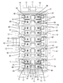
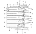
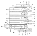
- FIG. 1 It is an exploded perspective view of a connector concerning an example of the present invention. It is a front view of a case. It is a front view of the case in which the housing was accommodated in the accommodation area. It is a sectional view similarly. Furthermore, it is sectional drawing showing the state by which the latching with a lock part and a lock receiving part is cancelled
- the housing extends from the position facing the lock receiving portion to the opposite side to the insertion direction to the housing and opens at the end surface, and the engagement between the lock portion and the lock receiving portion through the opening of the end surface
- a jig insertion hole capable of inserting a jig for releasing the stopper is provided.
- the lock receiving portion is provided inside the housing, and the lock portion is provided on the back surface of the housing area of the case, so that it is difficult to release the lock between the lock portion and the lock receiving portion. According to this, by inserting the jig into the jig insertion hole, the locking between the lock portion and the lock receiving portion can be easily released.
- the surface of the outer surface of the housing facing the adjacent housing when the housing is accommodated in the housing area does not have a lock structure, and can face and be in contact with the adjacent housing.
- the housings are held in a fitting jig (see reference numeral 50 in FIG. 6) or the like in a state where the housings are stacked in the row direction, and collectively held in the housing area of the case via the fitting jig or the like. And it becomes possible to fit.
- the connector of the present invention comprises a case 10 and a plurality of housings 60 which can be housed and held in the case 10.
- the case 10 is configured as a mating housing on which the bus bar 90 (see FIG. 2) is mounted, and the connector is configured as a so-called joint connector.
- the connector is configured as a so-called joint connector.
- the case 10 is made of a synthetic resin, and has a rectangular box shape that is long in the vertical direction as a whole, and is opened forward (see FIG. 1). As shown in FIGS. 2 and 3, on the outer surface of the case 10, the mounting lock portion 11 is provided to protrude on each of the four side surfaces, and a pair of guide walls 12 is provided on both sides across the mounting lock portion 11. It is provided extending in the front-rear direction.
- the case 10 is slidably mounted on a mounting member such as a bracket (not shown) while being guided by the guide wall 12 and fixed to the mounting member via the mounting lock portion 11.
- a bus bar 90 is disposed so as to protrude. Further, in the case 10, at a position corresponding to the projecting portion 91 of the bus bar 90, a plurality of accommodation areas 13 arranged in parallel in the vertical direction are provided. The housing 60 can be accommodated in each accommodation area 13 from the front.
- fitting recesses 14 extending in the front-rear direction and opening at the rear end of the case 10 are provided at every position corresponding to each housing area 13. Further, a guide groove 16 which extends in the front-rear direction and opens at the rear end of the case 10 is provided between the walls 15 which define the fitting recess 14 between the adjacent housing areas 13. Further, on both side walls of the case 10, a pair of stopper surfaces 17 are provided to be spread forward on both sides of each accommodation area 13. The case 10 is not provided with a wall for partitioning the adjacent storage areas 13.
- a lock portion 21 capable of holding the housing 60 in a retaining state is provided on the back surface 18 of each housing area 13 in the case 10.
- the lock portion 21 is cantilevered forward from the central portion in the width direction of the back surface 18 of the housing area 13 and can be bent and deformed in the vertical direction with the back surface 18 of the housing area 13 as a fulcrum .
- a claw-shaped lock protrusion 22 is provided to project upward at the tip of the lock portion 21.
- the front surface of the locking projection 22 has an arc shape in a side cross sectional view, and the rear surface of the locking projection 22 has a reverse taper shape that is inclined backward toward the projecting end (upper end).
- a mold removal hole 23 is provided which is opened when the mold passes when the rear surface of the lock projection 22 is molded.
- the lock portion 21 is disposed substantially at the center of each accommodation area 13 in a front view.
- the protruding portions 91 of the bus bar 90 are arranged in pairs on both sides of the lock portion 21.
- the housing 60 is made of synthetic resin, and has a flat block shape which is thin in the vertical direction as a whole (see FIG. 1). As shown in FIGS. 1 and 3, a pair of fitting grooves 61 extending in the front-rear direction is provided at both widthwise end portions of the upper surface of the housing 60, and both widthwise end portions of the lower surface of the housing 60 are: A pair of fitting ribs 62 extending in the front-rear direction is provided. Also, the fitting ribs 62 are configured to protrude on both sides of the housing 60.
- a fitting portion 63 is provided which protrudes one step outward from the front portion 64 side.
- the fitting portion 63 can be fitted in the fitting recess 14 in a state where the housing 60 is housed in the housing area 13.
- the laterally protruding portion of the fitting rib 62 is fitted in the guide groove 16 so that the housing 60 is inserted while being guided in the housing area 13.
- the stopper part 65 which overhangs to the side is provided.
- the front end of the stopper portion 65 abuts against the stopper surface 17 to restrict the housing 60 from entering deeper into the housing area 13 (see FIG. 3). Then, in a state where the housing 60 is properly accommodated in the accommodation area 13, the rear end portion including the stopper portion 65 of the housing 60 is disposed to be exposed to the rear of the housing 60.
- a lock hole 66 into which the lock portion 21 can be inserted is provided at the center in the width direction of the housing 60.
- the lock hole 66 has an opening shape having a substantially rectangular cross section, and as shown in FIG. 4, is configured to penetrate the housing 60 in the front-rear direction.
- a hook-shaped lock receiving portion 67 is provided on the upper surface of the front end portion of the locking hole 66 of the housing 60 so as to protrude downward.
- the front end of the lock receiving portion 67 has a tapered shape that is inclined backward toward the protruding end (lower end), and the rear surface of the lock receiving portion 67 has a reverse tapered shape that is slightly inclined toward the protruding end.
- the lock protrusion 22 of the lock portion 21 can be locked to the lock receiving portion 67.
- the protrusion amount of the lock receiving portion 67 is set to be substantially the same as the protrusion amount of the lock protrusion 22.
- a partition wall 68 which divides the substantially rear half of the lock hole 66 into upper and lower portions. Specifically, the partition wall 68 is disposed slightly lower than the vertical center of the lock hole 66.
- a jig insertion hole 69 extending in the front-rear direction from the rear surface of the lock receiving portion 67 to the rear end opening of the housing 60 is provided in the upper region of the lock hole 66 divided by the partition wall 68. As shown in FIG.
- a jig 80 for releasing the lock is guided and inserted into the jig insertion hole 69 from the rear end opening of the housing 60, and the lock portion 21 and the lock receiving portion are inserted by the inserted jig 80. It is possible to release the lock with 67.
- cavities 71 are provided in pairs on both sides of the lock hole 66.
- a terminal fitting 75 is inserted into and accommodated in each cavity 71 from the rear.
- the terminal fitting 75 is connected to an end portion of a wire (not shown), and is electrically connected to the bus bar 90 in a state where the housing 60 is accommodated in the accommodation area 13.
- the housing 60 in the case 10 first, the housing 60 is vertically stacked. Specifically, the respective housings 60 are stacked so that the lower surface of the upper housing 60 substantially closely contacts the upper surface of the lower housing 60. At this time, by fitting the fitting rib 62 of the upper housing 60 into the fitting groove 61 of the lower housing 60, positional deviation of the adjacent housings 60 in the vertical direction in the width direction is restricted. (See Figure 3).
- the stacked state of the housing 60 described above is stably held by using the fitting jig 50 shown in FIG.
- the fitting jig 50 has a gate-like frame shape, and the rear end portion of each housing 60 (a portion exposed to the outside in a state where the housing 60 is accommodated in the accommodation area 13) ) Can be held in a stacked state.
- the fitting jig 50 is made to approach the case 10 in a state where the respective housings 60 face the corresponding housing areas 13. Then, the respective housings 60 are collectively inserted into the corresponding housing area 13. In the process of inserting the housing 60 into the housing area 13, the lock projection 22 interferes with the lock receiving portion 67 and the lock portion 21 is bent and deformed. Further, in the insertion process, the fitting rib 62 of the housing 60 is inserted into the guide groove 16 to guide the insertion operation of the housing 60. When the housing 60 is properly inserted into the housing area 13, the fitting portion 63 is fitted into the fitting recess 14, and the stopper portion 65 abuts against the stopper surface 17 to restrict further insertion operation. . Further, as shown in FIG.
- the jig 80 for releasing the lock is inserted into the jig insertion hole 69 from the rear end opening of the housing 60.
- the jig 80 has a pin-shaped jig body 81 elongated in the front-rear direction, and the jig body 81 is inserted straight while being guided by the jig insertion hole 69.
- the tip end of the jig body 81 interferes with the lock projection 22 and the lock portion 21 is bent downward.
- the lock projection 22 is separated from the lock receiving portion 67, and the locking between the lock portion 21 and the lock receiving portion 67 is released.
- the housing 60 can be detached from the case 10.
- the lock receiving portion 67 is provided inside the housing 60 and the lock portion 21 is provided on the back surface 18 of the housing area 13 in the case 10, the housing 60
- the lock receiving portion 67 does not protrude to the outside or the lock portion 21 does not protrude to the outside of the case 10, and the connector can be prevented from becoming large in the vertical direction (the direction in which the housings 60 are aligned).
- the lock receiving portion 67 does not protrude outside the housing 60, the plurality of housings 60 can be stacked in the vertical direction without any problem.
- the respective housings 60 in the laminated state can be fitted together in the case 10 through the fitting jig 50, the workability can be further improved. .
- the jig 80 for releasing the lock into the jig insertion hole 69 through the rear end opening of the housing 60, the lock between the lock portion 21 and the lock receiving portion 67 can be easily released.
- the adjacent housings may not be in contact with each other when the housings are housed in the housing area of the case.
- the case may be provided with a partition wall which divides adjacent housings.
- the case may be one for housing the housing without the bus bar mounted inside.
Landscapes
- Connector Housings Or Holding Contact Members (AREA)
- Details Of Connecting Devices For Male And Female Coupling (AREA)
Abstract
La présente invention permet d'empiler une pluralité de boîtiers sans augmenter la taille d'un connecteur. Le connecteur est pourvu des éléments suivants : des boîtiers (60) pourvus de sections de réception de verrou (67) placées sur leur côté intérieur ; et un coffret (10) comportant une zone de logement (13) qui peut loger une pluralité des boîtiers (60) en parallèle sur le côté intérieur de la zone de logement, le coffret étant pourvu de sections de verrou (21) sur des surfaces lointaines (18) de la zone de stockage (13), les sections de verrou limitant la possibilité des boîtiers (60) de se détacher de la zone de stockage (13) par mise en prise élastique avec les sections de réception de verrou (67) des boîtiers (60) respectifs.
Priority Applications (2)
| Application Number | Priority Date | Filing Date | Title |
|---|---|---|---|
| CN201580063921.5A CN107004994B (zh) | 2014-11-28 | 2015-11-09 | 连接器 |
| US15/523,967 US9972938B2 (en) | 2014-11-28 | 2015-11-09 | Connector |
Applications Claiming Priority (2)
| Application Number | Priority Date | Filing Date | Title |
|---|---|---|---|
| JP2014-240874 | 2014-11-28 | ||
| JP2014240874A JP6222574B2 (ja) | 2014-11-28 | 2014-11-28 | コネクタ |
Publications (1)
| Publication Number | Publication Date |
|---|---|
| WO2016084587A1 true WO2016084587A1 (fr) | 2016-06-02 |
Family
ID=56074157
Family Applications (1)
| Application Number | Title | Priority Date | Filing Date |
|---|---|---|---|
| PCT/JP2015/081442 WO2016084587A1 (fr) | 2014-11-28 | 2015-11-09 | Connecteur |
Country Status (4)
| Country | Link |
|---|---|
| US (1) | US9972938B2 (fr) |
| JP (1) | JP6222574B2 (fr) |
| CN (1) | CN107004994B (fr) |
| WO (1) | WO2016084587A1 (fr) |
Families Citing this family (9)
| Publication number | Priority date | Publication date | Assignee | Title |
|---|---|---|---|---|
| DE102017125859A1 (de) * | 2017-11-06 | 2019-05-09 | Harting Electric Gmbh & Co. Kg | Modularer Halterahmen für Steckverbinder |
| JP2019091560A (ja) * | 2017-11-13 | 2019-06-13 | 株式会社オートネットワーク技術研究所 | コネクタ、治具、及びコネクタの製造方法 |
| US10177498B1 (en) * | 2018-02-19 | 2019-01-08 | Te Connectivity Corporation | Stacking electrical connector |
| JP7042420B2 (ja) * | 2018-10-24 | 2022-03-28 | 住友電装株式会社 | 積層コネクタ |
| JP2020155360A (ja) * | 2019-03-22 | 2020-09-24 | 住友電装株式会社 | コネクタ |
| JP7303537B2 (ja) * | 2019-05-16 | 2023-07-05 | 日本圧着端子製造株式会社 | コネクタ連結構造、連結具及びコネクタ |
| JP2021082563A (ja) * | 2019-11-22 | 2021-05-27 | スリーエム イノベイティブ プロパティズ カンパニー | ウェハコネクタ及び嵌合コネクタ |
| JP7470289B2 (ja) * | 2020-08-27 | 2024-04-18 | 住友電装株式会社 | コネクタ |
| JP7393105B2 (ja) | 2021-03-19 | 2023-12-06 | トヨタ自動車株式会社 | コネクタ接続方法およびコネクタセット |
Citations (2)
| Publication number | Priority date | Publication date | Assignee | Title |
|---|---|---|---|---|
| JPH0574514A (ja) * | 1991-09-10 | 1993-03-26 | Sumitomo Wiring Syst Ltd | 集合コネクタ |
| JP3813711B2 (ja) * | 1997-10-02 | 2006-08-23 | 矢崎総業株式会社 | 合体コネクタ |
Family Cites Families (15)
| Publication number | Priority date | Publication date | Assignee | Title |
|---|---|---|---|---|
| JP2555733Y2 (ja) * | 1991-12-25 | 1997-11-26 | 住友電装株式会社 | コネクタ |
| ES1026401Y (es) * | 1993-11-26 | 1995-04-01 | Mecanismos Aux Ind | Sistema modular de conectores. |
| JP2921639B2 (ja) * | 1994-03-07 | 1999-07-19 | 矢崎総業株式会社 | 二重係止コネクタ及びその係止解除構造 |
| JP2929413B2 (ja) * | 1994-06-17 | 1999-08-03 | 矢崎総業株式会社 | 高密度多極コネクタへのオプションコネクタの嵌合方法及びその嵌合構造 |
| US5612854A (en) * | 1995-01-24 | 1997-03-18 | Dell Usa, L.P. | Computer power supply apparatus |
| JP3214284B2 (ja) * | 1995-03-10 | 2001-10-02 | 住友電装株式会社 | 電気接続箱 |
| JP3067597B2 (ja) | 1995-06-27 | 2000-07-17 | 住友電装株式会社 | コネクタ |
| US5992953A (en) * | 1996-03-08 | 1999-11-30 | Rabinovitz; Josef | Adjustable interlocking system for computer peripheral and other desktop enclosures |
| US5788347A (en) * | 1996-03-08 | 1998-08-04 | Rabinovitz; Josef | Interlocking system for computer peripheral enclosures and the like |
| JP3651254B2 (ja) * | 1998-04-15 | 2005-05-25 | 住友電装株式会社 | コネクタ |
| FR2838879B1 (fr) * | 2002-04-23 | 2004-06-04 | Entrelec | Dispositif de connexion d'un boitier electronique |
| US7445471B1 (en) * | 2007-07-13 | 2008-11-04 | 3M Innovative Properties Company | Electrical connector assembly with carrier |
| JP4823285B2 (ja) * | 2008-09-19 | 2011-11-24 | タイコエレクトロニクスジャパン合同会社 | 電気コネクタ |
| JP5812429B2 (ja) * | 2012-03-09 | 2015-11-11 | 住友電装株式会社 | 電気接続箱 |
| JP5747866B2 (ja) * | 2012-05-25 | 2015-07-15 | 住友電装株式会社 | 治具 |
-
2014
- 2014-11-28 JP JP2014240874A patent/JP6222574B2/ja active Active
-
2015
- 2015-11-09 US US15/523,967 patent/US9972938B2/en active Active
- 2015-11-09 WO PCT/JP2015/081442 patent/WO2016084587A1/fr active Application Filing
- 2015-11-09 CN CN201580063921.5A patent/CN107004994B/zh active Active
Patent Citations (2)
| Publication number | Priority date | Publication date | Assignee | Title |
|---|---|---|---|---|
| JPH0574514A (ja) * | 1991-09-10 | 1993-03-26 | Sumitomo Wiring Syst Ltd | 集合コネクタ |
| JP3813711B2 (ja) * | 1997-10-02 | 2006-08-23 | 矢崎総業株式会社 | 合体コネクタ |
Also Published As
| Publication number | Publication date |
|---|---|
| CN107004994A (zh) | 2017-08-01 |
| JP6222574B2 (ja) | 2017-11-01 |
| US20170346230A1 (en) | 2017-11-30 |
| JP2016103393A (ja) | 2016-06-02 |
| US9972938B2 (en) | 2018-05-15 |
| CN107004994B (zh) | 2019-04-02 |
Similar Documents
| Publication | Publication Date | Title |
|---|---|---|
| WO2016084587A1 (fr) | Connecteur | |
| JP5724836B2 (ja) | コネクタ | |
| US9379473B2 (en) | Connector | |
| US9413095B2 (en) | Connector | |
| JP2013058371A (ja) | 電気コネクタ | |
| JP2012084351A (ja) | コネクタ | |
| JP6176544B2 (ja) | コネクタ | |
| JP6352676B2 (ja) | コネクタ | |
| JP2006100227A (ja) | コネクタ | |
| JP2005183297A (ja) | コネクタ | |
| JP6057468B2 (ja) | 防水コネクタ | |
| JP5814316B2 (ja) | コネクタ | |
| US6702628B2 (en) | Connector and a method of assembling it | |
| US6994597B2 (en) | Connector enabling secure retention of contacts relative to insulator | |
| JP5768925B2 (ja) | コネクタ | |
| JP5907390B2 (ja) | コネクタ | |
| JP2005166611A (ja) | コネクタ | |
| JP2007026948A (ja) | 分割コネクタ | |
| JP2006059597A (ja) | ジョイントコネクタ | |
| JP2013008516A (ja) | コネクタ | |
| JP5565184B2 (ja) | コネクタ | |
| JP5330956B2 (ja) | 電気コネクタ | |
| JP2008098021A (ja) | コネクタ | |
| JP6491008B2 (ja) | コネクタの接続構造 | |
| JP2016115461A (ja) | コネクタ |
Legal Events
| Date | Code | Title | Description |
|---|---|---|---|
| 121 | Ep: the epo has been informed by wipo that ep was designated in this application |
Ref document number: 15863970 Country of ref document: EP Kind code of ref document: A1 |
|
| WWE | Wipo information: entry into national phase |
Ref document number: 15523967 Country of ref document: US |
|
| NENP | Non-entry into the national phase |
Ref country code: DE |
|
| 122 | Ep: pct application non-entry in european phase |
Ref document number: 15863970 Country of ref document: EP Kind code of ref document: A1 |