WO2016084587A1 - Connector - Google Patents
Connector Download PDFInfo
- Publication number
- WO2016084587A1 WO2016084587A1 PCT/JP2015/081442 JP2015081442W WO2016084587A1 WO 2016084587 A1 WO2016084587 A1 WO 2016084587A1 JP 2015081442 W JP2015081442 W JP 2015081442W WO 2016084587 A1 WO2016084587 A1 WO 2016084587A1
- Authority
- WO
- WIPO (PCT)
- Prior art keywords
- housing
- lock
- case
- housings
- receiving portion
- Prior art date
Links
Images


Classifications
-
- H—ELECTRICITY
- H01—ELECTRIC ELEMENTS
- H01R—ELECTRICALLY-CONDUCTIVE CONNECTIONS; STRUCTURAL ASSOCIATIONS OF A PLURALITY OF MUTUALLY-INSULATED ELECTRICAL CONNECTING ELEMENTS; COUPLING DEVICES; CURRENT COLLECTORS
- H01R13/00—Details of coupling devices of the kinds covered by groups H01R12/70 or H01R24/00 - H01R33/00
- H01R13/62—Means for facilitating engagement or disengagement of coupling parts or for holding them in engagement
- H01R13/639—Additional means for holding or locking coupling parts together, after engagement, e.g. separate keylock, retainer strap
-
- H—ELECTRICITY
- H01—ELECTRIC ELEMENTS
- H01R—ELECTRICALLY-CONDUCTIVE CONNECTIONS; STRUCTURAL ASSOCIATIONS OF A PLURALITY OF MUTUALLY-INSULATED ELECTRICAL CONNECTING ELEMENTS; COUPLING DEVICES; CURRENT COLLECTORS
- H01R13/00—Details of coupling devices of the kinds covered by groups H01R12/70 or H01R24/00 - H01R33/00
- H01R13/46—Bases; Cases
- H01R13/514—Bases; Cases composed as a modular blocks or assembly, i.e. composed of co-operating parts provided with contact members or holding contact members between them
-
- H—ELECTRICITY
- H01—ELECTRIC ELEMENTS
- H01R—ELECTRICALLY-CONDUCTIVE CONNECTIONS; STRUCTURAL ASSOCIATIONS OF A PLURALITY OF MUTUALLY-INSULATED ELECTRICAL CONNECTING ELEMENTS; COUPLING DEVICES; CURRENT COLLECTORS
- H01R13/00—Details of coupling devices of the kinds covered by groups H01R12/70 or H01R24/00 - H01R33/00
- H01R13/46—Bases; Cases
- H01R13/516—Means for holding or embracing insulating body, e.g. casing, hoods
- H01R13/518—Means for holding or embracing insulating body, e.g. casing, hoods for holding or embracing several coupling parts, e.g. frames
-
- H—ELECTRICITY
- H01—ELECTRIC ELEMENTS
- H01R—ELECTRICALLY-CONDUCTIVE CONNECTIONS; STRUCTURAL ASSOCIATIONS OF A PLURALITY OF MUTUALLY-INSULATED ELECTRICAL CONNECTING ELEMENTS; COUPLING DEVICES; CURRENT COLLECTORS
- H01R13/00—Details of coupling devices of the kinds covered by groups H01R12/70 or H01R24/00 - H01R33/00
- H01R13/46—Bases; Cases
- H01R13/52—Dustproof, splashproof, drip-proof, waterproof, or flameproof cases
- H01R13/5202—Sealing means between parts of housing or between housing part and a wall, e.g. sealing rings
-
- H—ELECTRICITY
- H01—ELECTRIC ELEMENTS
- H01R—ELECTRICALLY-CONDUCTIVE CONNECTIONS; STRUCTURAL ASSOCIATIONS OF A PLURALITY OF MUTUALLY-INSULATED ELECTRICAL CONNECTING ELEMENTS; COUPLING DEVICES; CURRENT COLLECTORS
- H01R31/00—Coupling parts supported only by co-operation with counterpart
- H01R31/08—Short-circuiting members for bridging contacts in a counterpart
-
- H—ELECTRICITY
- H01—ELECTRIC ELEMENTS
- H01R—ELECTRICALLY-CONDUCTIVE CONNECTIONS; STRUCTURAL ASSOCIATIONS OF A PLURALITY OF MUTUALLY-INSULATED ELECTRICAL CONNECTING ELEMENTS; COUPLING DEVICES; CURRENT COLLECTORS
- H01R33/00—Coupling devices specially adapted for supporting apparatus and having one part acting as a holder providing support and electrical connection via a counterpart which is structurally associated with the apparatus, e.g. lamp holders; Separate parts thereof
- H01R33/74—Devices having four or more poles, e.g. holders for compact fluorescent lamps
- H01R33/76—Holders with sockets, clips, or analogous contacts adapted for axially-sliding engagement with parallely-arranged pins, blades, or analogous contacts on counterpart, e.g. electronic tube socket
- H01R33/7671—Holders with sockets, clips, or analogous contacts adapted for axially-sliding engagement with parallely-arranged pins, blades, or analogous contacts on counterpart, e.g. electronic tube socket having multiple positions or sockets, e.g. stacked sockets while mounting
Definitions
- the present invention relates to a connector.
- the connector disclosed in Patent Document 1 includes male and female housings that can be fitted to each other.
- the male housing has two fitting recesses (accommodating regions), and a pair of flanges are provided so as to project at both ends sandwiching the fitting recesses.
- the female housing has a block shape, and an elastic locking piece is provided on the outer surface thereof so as to protrude.
- a female housing is fitted in each of the fitting recesses.
- the female housing is configured to be held in a state of being retained in the fitting recess by elastically locking the elastic locking piece to the collar portion in a state of being accommodated in the fitting recess.
- the present invention has been completed based on the above-described circumstances, and an object of the present invention is to make it possible to stack a plurality of housings without increasing the size of the connector.
- the present invention has a housing provided with a lock receiving portion inside, and a receiving area capable of receiving a plurality of the housings in parallel inside, and the lock receiving part of each of the housings at the back of the receiving area. , And a case provided with a lock portion for restricting the detachment of the housing from the housing area.
- the lock receiving portion is provided on the inside of the housing, and the lock portion is provided on the back surface of the housing area in the case, so the lock receiving portion protrudes to the outside of the housing or the lock portion protrudes to the outside of the case It is possible to prevent the connector from becoming large in the arranging direction of the housings. Moreover, if it is the structure which a lock
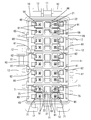
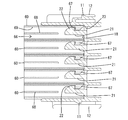
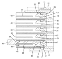
- FIG. 1 It is an exploded perspective view of a connector concerning an example of the present invention. It is a front view of a case. It is a front view of the case in which the housing was accommodated in the accommodation area. It is a sectional view similarly. Furthermore, it is sectional drawing showing the state by which the latching with a lock part and a lock receiving part is cancelled
- the housing extends from the position facing the lock receiving portion to the opposite side to the insertion direction to the housing and opens at the end surface, and the engagement between the lock portion and the lock receiving portion through the opening of the end surface
- a jig insertion hole capable of inserting a jig for releasing the stopper is provided.
- the lock receiving portion is provided inside the housing, and the lock portion is provided on the back surface of the housing area of the case, so that it is difficult to release the lock between the lock portion and the lock receiving portion. According to this, by inserting the jig into the jig insertion hole, the locking between the lock portion and the lock receiving portion can be easily released.
- the surface of the outer surface of the housing facing the adjacent housing when the housing is accommodated in the housing area does not have a lock structure, and can face and be in contact with the adjacent housing.
- the housings are held in a fitting jig (see reference numeral 50 in FIG. 6) or the like in a state where the housings are stacked in the row direction, and collectively held in the housing area of the case via the fitting jig or the like. And it becomes possible to fit.
- the connector of the present invention comprises a case 10 and a plurality of housings 60 which can be housed and held in the case 10.
- the case 10 is configured as a mating housing on which the bus bar 90 (see FIG. 2) is mounted, and the connector is configured as a so-called joint connector.
- the connector is configured as a so-called joint connector.
- the case 10 is made of a synthetic resin, and has a rectangular box shape that is long in the vertical direction as a whole, and is opened forward (see FIG. 1). As shown in FIGS. 2 and 3, on the outer surface of the case 10, the mounting lock portion 11 is provided to protrude on each of the four side surfaces, and a pair of guide walls 12 is provided on both sides across the mounting lock portion 11. It is provided extending in the front-rear direction.
- the case 10 is slidably mounted on a mounting member such as a bracket (not shown) while being guided by the guide wall 12 and fixed to the mounting member via the mounting lock portion 11.
- a bus bar 90 is disposed so as to protrude. Further, in the case 10, at a position corresponding to the projecting portion 91 of the bus bar 90, a plurality of accommodation areas 13 arranged in parallel in the vertical direction are provided. The housing 60 can be accommodated in each accommodation area 13 from the front.
- fitting recesses 14 extending in the front-rear direction and opening at the rear end of the case 10 are provided at every position corresponding to each housing area 13. Further, a guide groove 16 which extends in the front-rear direction and opens at the rear end of the case 10 is provided between the walls 15 which define the fitting recess 14 between the adjacent housing areas 13. Further, on both side walls of the case 10, a pair of stopper surfaces 17 are provided to be spread forward on both sides of each accommodation area 13. The case 10 is not provided with a wall for partitioning the adjacent storage areas 13.
- a lock portion 21 capable of holding the housing 60 in a retaining state is provided on the back surface 18 of each housing area 13 in the case 10.
- the lock portion 21 is cantilevered forward from the central portion in the width direction of the back surface 18 of the housing area 13 and can be bent and deformed in the vertical direction with the back surface 18 of the housing area 13 as a fulcrum .
- a claw-shaped lock protrusion 22 is provided to project upward at the tip of the lock portion 21.
- the front surface of the locking projection 22 has an arc shape in a side cross sectional view, and the rear surface of the locking projection 22 has a reverse taper shape that is inclined backward toward the projecting end (upper end).
- a mold removal hole 23 is provided which is opened when the mold passes when the rear surface of the lock projection 22 is molded.
- the lock portion 21 is disposed substantially at the center of each accommodation area 13 in a front view.
- the protruding portions 91 of the bus bar 90 are arranged in pairs on both sides of the lock portion 21.
- the housing 60 is made of synthetic resin, and has a flat block shape which is thin in the vertical direction as a whole (see FIG. 1). As shown in FIGS. 1 and 3, a pair of fitting grooves 61 extending in the front-rear direction is provided at both widthwise end portions of the upper surface of the housing 60, and both widthwise end portions of the lower surface of the housing 60 are: A pair of fitting ribs 62 extending in the front-rear direction is provided. Also, the fitting ribs 62 are configured to protrude on both sides of the housing 60.
- a fitting portion 63 is provided which protrudes one step outward from the front portion 64 side.
- the fitting portion 63 can be fitted in the fitting recess 14 in a state where the housing 60 is housed in the housing area 13.
- the laterally protruding portion of the fitting rib 62 is fitted in the guide groove 16 so that the housing 60 is inserted while being guided in the housing area 13.
- the stopper part 65 which overhangs to the side is provided.
- the front end of the stopper portion 65 abuts against the stopper surface 17 to restrict the housing 60 from entering deeper into the housing area 13 (see FIG. 3). Then, in a state where the housing 60 is properly accommodated in the accommodation area 13, the rear end portion including the stopper portion 65 of the housing 60 is disposed to be exposed to the rear of the housing 60.
- a lock hole 66 into which the lock portion 21 can be inserted is provided at the center in the width direction of the housing 60.
- the lock hole 66 has an opening shape having a substantially rectangular cross section, and as shown in FIG. 4, is configured to penetrate the housing 60 in the front-rear direction.
- a hook-shaped lock receiving portion 67 is provided on the upper surface of the front end portion of the locking hole 66 of the housing 60 so as to protrude downward.
- the front end of the lock receiving portion 67 has a tapered shape that is inclined backward toward the protruding end (lower end), and the rear surface of the lock receiving portion 67 has a reverse tapered shape that is slightly inclined toward the protruding end.
- the lock protrusion 22 of the lock portion 21 can be locked to the lock receiving portion 67.
- the protrusion amount of the lock receiving portion 67 is set to be substantially the same as the protrusion amount of the lock protrusion 22.
- a partition wall 68 which divides the substantially rear half of the lock hole 66 into upper and lower portions. Specifically, the partition wall 68 is disposed slightly lower than the vertical center of the lock hole 66.
- a jig insertion hole 69 extending in the front-rear direction from the rear surface of the lock receiving portion 67 to the rear end opening of the housing 60 is provided in the upper region of the lock hole 66 divided by the partition wall 68. As shown in FIG.
- a jig 80 for releasing the lock is guided and inserted into the jig insertion hole 69 from the rear end opening of the housing 60, and the lock portion 21 and the lock receiving portion are inserted by the inserted jig 80. It is possible to release the lock with 67.
- cavities 71 are provided in pairs on both sides of the lock hole 66.
- a terminal fitting 75 is inserted into and accommodated in each cavity 71 from the rear.
- the terminal fitting 75 is connected to an end portion of a wire (not shown), and is electrically connected to the bus bar 90 in a state where the housing 60 is accommodated in the accommodation area 13.
- the housing 60 in the case 10 first, the housing 60 is vertically stacked. Specifically, the respective housings 60 are stacked so that the lower surface of the upper housing 60 substantially closely contacts the upper surface of the lower housing 60. At this time, by fitting the fitting rib 62 of the upper housing 60 into the fitting groove 61 of the lower housing 60, positional deviation of the adjacent housings 60 in the vertical direction in the width direction is restricted. (See Figure 3).
- the stacked state of the housing 60 described above is stably held by using the fitting jig 50 shown in FIG.
- the fitting jig 50 has a gate-like frame shape, and the rear end portion of each housing 60 (a portion exposed to the outside in a state where the housing 60 is accommodated in the accommodation area 13) ) Can be held in a stacked state.
- the fitting jig 50 is made to approach the case 10 in a state where the respective housings 60 face the corresponding housing areas 13. Then, the respective housings 60 are collectively inserted into the corresponding housing area 13. In the process of inserting the housing 60 into the housing area 13, the lock projection 22 interferes with the lock receiving portion 67 and the lock portion 21 is bent and deformed. Further, in the insertion process, the fitting rib 62 of the housing 60 is inserted into the guide groove 16 to guide the insertion operation of the housing 60. When the housing 60 is properly inserted into the housing area 13, the fitting portion 63 is fitted into the fitting recess 14, and the stopper portion 65 abuts against the stopper surface 17 to restrict further insertion operation. . Further, as shown in FIG.
- the jig 80 for releasing the lock is inserted into the jig insertion hole 69 from the rear end opening of the housing 60.
- the jig 80 has a pin-shaped jig body 81 elongated in the front-rear direction, and the jig body 81 is inserted straight while being guided by the jig insertion hole 69.
- the tip end of the jig body 81 interferes with the lock projection 22 and the lock portion 21 is bent downward.
- the lock projection 22 is separated from the lock receiving portion 67, and the locking between the lock portion 21 and the lock receiving portion 67 is released.
- the housing 60 can be detached from the case 10.
- the lock receiving portion 67 is provided inside the housing 60 and the lock portion 21 is provided on the back surface 18 of the housing area 13 in the case 10, the housing 60
- the lock receiving portion 67 does not protrude to the outside or the lock portion 21 does not protrude to the outside of the case 10, and the connector can be prevented from becoming large in the vertical direction (the direction in which the housings 60 are aligned).
- the lock receiving portion 67 does not protrude outside the housing 60, the plurality of housings 60 can be stacked in the vertical direction without any problem.
- the respective housings 60 in the laminated state can be fitted together in the case 10 through the fitting jig 50, the workability can be further improved. .
- the jig 80 for releasing the lock into the jig insertion hole 69 through the rear end opening of the housing 60, the lock between the lock portion 21 and the lock receiving portion 67 can be easily released.
- the adjacent housings may not be in contact with each other when the housings are housed in the housing area of the case.
- the case may be provided with a partition wall which divides adjacent housings.
- the case may be one for housing the housing without the bus bar mounted inside.
Abstract
The present invention enables the stacking of a plurality of housings without increasing the size of a connector. The connector is provided with the following: housings (60) with lock reception sections (67) provided on the inner side thereof; and a case (10) having an accommodation region (13) that can accommodate a plurality of the housings (60) in parallel on the inner side of the accommodation region, the case being provided with lock sections (21) on far surfaces (18) of the storage region (13), the lock sections restricting detachment of the housings (60) from the storage region (13) by elastically engaging with the lock reception sections (67) of the respective housings (60).
Description
本発明は、コネクタに関する。
The present invention relates to a connector.
特許文献1に開示のコネクタは、互いに嵌合可能な雌雄夫々のハウジングを備えている。雄ハウジングは、2つの嵌合凹部(収容領域)を有し、両嵌合凹部を挟んだ両端部に一対の鈎部が突出して設けられている。雌ハウジングは、ブロック状をなし、その外面に弾性係止片が突出して設けられている。両嵌合凹部内には、それぞれ雌ハウジングが嵌合される。雌ハウジングは、嵌合凹部に収容された状態で、鈎部に弾性係止片を弾性的に係止させることにより、嵌合凹部に抜け止めされた状態で保持されるようになっている。
The connector disclosed in Patent Document 1 includes male and female housings that can be fitted to each other. The male housing has two fitting recesses (accommodating regions), and a pair of flanges are provided so as to project at both ends sandwiching the fitting recesses. The female housing has a block shape, and an elastic locking piece is provided on the outer surface thereof so as to protrude. A female housing is fitted in each of the fitting recesses. The female housing is configured to be held in a state of being retained in the fitting recess by elastically locking the elastic locking piece to the collar portion in a state of being accommodated in the fitting recess.
上記の場合、雄ハウジングにおける両嵌合凹部を挟んだ両端部に一対の鈎部が突出して設けられるため、雄ハウジングひいてはコネクタ全体が両嵌合凹部の並び方向に大型化するという問題がある。また、雌ハウジングの外面に弾性係止片が突出して設けられるため、例えば、複数の雌ハウジングを積層状態に保持して雄ハウジングに一括して嵌合しようとしても、弾性係止片が邪魔になって、各雌ハウジングの積層状態を維持することができないという問題もある。
In the above case, a pair of flanges are provided projecting at both ends of the male housing sandwiching the both fitting recesses, so that there is a problem that the size of the male housing and the connector as a whole increase in the arranging direction of both fitting recesses. Further, since the elastic locking pieces are provided on the outer surface of the female housing so as to protrude, for example, even if it is intended to hold a plurality of female housings in a stacked state and collectively fit in the male housing, the elastic locking pieces are obstructive As a result, there is also a problem that the laminated state of each female housing can not be maintained.
本発明は上記のような事情に基づいて完成されたものであって、コネクタを大型化することなく、複数のハウジングを積層可能とすることを目的とする。
The present invention has been completed based on the above-described circumstances, and an object of the present invention is to make it possible to stack a plurality of housings without increasing the size of the connector.
本発明は、内側にロック受部が設けられたハウジングと、内側に複数の前記ハウジングを並列に収容可能な収容領域を有し、前記収容領域の奥面に、前記各ハウジングの前記ロック受部を弾性的に係止して前記ハウジングの前記収容領域からの離脱を規制するロック部が設けられたケースとを備えているところに特徴を有する。
The present invention has a housing provided with a lock receiving portion inside, and a receiving area capable of receiving a plurality of the housings in parallel inside, and the lock receiving part of each of the housings at the back of the receiving area. , And a case provided with a lock portion for restricting the detachment of the housing from the housing area.
ロック受部がハウジングの内側に設けられ、ロック部がケース内の収容領域の奥面に設けられているから、ハウジングの外側にロック受部が突出したり、ケースの外側にロック部が突出したりすることがなく、ハウジングの並び方向に関してコネクタが大型になるのを防止することができる。また、ハウジングの外側にロック受部が突出しない構造であれば、複数のハウジングを並び方向に積層させることができる。
The lock receiving portion is provided on the inside of the housing, and the lock portion is provided on the back surface of the housing area in the case, so the lock receiving portion protrudes to the outside of the housing or the lock portion protrudes to the outside of the case It is possible to prevent the connector from becoming large in the arranging direction of the housings. Moreover, if it is the structure which a lock | rock receiving part does not protrude outside the housing, a plurality of housings can be stacked in a row direction.
本発明の好ましい実施形態を以下に示す。
前記ハウジングには、前記ロック受部に臨む位置から前記ハウジングへの挿入方向と反対側に延出して端面に開口する形態をなし、前記端面の開口を通して前記ロック部と前記ロック受部との係止を解除するための治具を挿入可能な治具挿入孔が設けられている。ハウジングの内側にロック受部が設けられ、ケースの収容領域の奥面にロック部が設けられているため、ロック部とロック受部との係止を解除しづらいという事情があるものの、本構成によれば、治具挿入孔に治具を挿入することにより、ロック部とロック受部との係止を容易に解除することができる。 Preferred embodiments of the present invention are shown below.
The housing extends from the position facing the lock receiving portion to the opposite side to the insertion direction to the housing and opens at the end surface, and the engagement between the lock portion and the lock receiving portion through the opening of the end surface A jig insertion hole capable of inserting a jig for releasing the stopper is provided. The lock receiving portion is provided inside the housing, and the lock portion is provided on the back surface of the housing area of the case, so that it is difficult to release the lock between the lock portion and the lock receiving portion. According to this, by inserting the jig into the jig insertion hole, the locking between the lock portion and the lock receiving portion can be easily released.
前記ハウジングの外面のうち、前記ハウジングが前記収容領域に収容された状態で隣接するハウジングと対向する面は、ロック構造を有さず、前記隣接するハウジングと対面して当接可能とされている。これによれば、各ハウジングを並び方向に積層させた状態で嵌合治具(図6の符号50を参照)等に保持させ、嵌合治具等を介して、ケースの収容領域内に一括して嵌合することが可能となる。
The surface of the outer surface of the housing facing the adjacent housing when the housing is accommodated in the housing area does not have a lock structure, and can face and be in contact with the adjacent housing. . According to this, the housings are held in a fitting jig (see reference numeral 50 in FIG. 6) or the like in a state where the housings are stacked in the row direction, and collectively held in the housing area of the case via the fitting jig or the like. And it becomes possible to fit.
<実施例>
以下、実施例を図面に基づいて説明する。本発明のコネクタは、ケース10と、ケース10内に収容されて保持可能な複数のハウジング60とを備えている。ケース10は、バスバー90(図2を参照)を装着した相手ハウジングとして構成され、コネクタは、いわゆるジョイントコネクタとして構成されている。なお、以下の説明において前後方向については、ケース10内にハウジング60を収容させる際にハウジング60とケース10とが互いに向き合う面側を前側とし、上下方向については、図2~図5を基準とする。 <Example>
Hereinafter, an embodiment will be described based on the drawings. The connector of the present invention comprises acase 10 and a plurality of housings 60 which can be housed and held in the case 10. The case 10 is configured as a mating housing on which the bus bar 90 (see FIG. 2) is mounted, and the connector is configured as a so-called joint connector. In the following description, in the front-rear direction, when housing 60 is housed in case 10, the side on which housing 60 and case 10 face each other is the front side, and in the vertical direction, FIGS. Do.
以下、実施例を図面に基づいて説明する。本発明のコネクタは、ケース10と、ケース10内に収容されて保持可能な複数のハウジング60とを備えている。ケース10は、バスバー90(図2を参照)を装着した相手ハウジングとして構成され、コネクタは、いわゆるジョイントコネクタとして構成されている。なお、以下の説明において前後方向については、ケース10内にハウジング60を収容させる際にハウジング60とケース10とが互いに向き合う面側を前側とし、上下方向については、図2~図5を基準とする。 <Example>
Hereinafter, an embodiment will be described based on the drawings. The connector of the present invention comprises a
ケース10は合成樹脂製であって、全体として上下方向に長い角箱状をなし、前方に開放されている(図1を参照)。図2及び図3に示すように、ケース10の外面には、4つの側面のそれぞれに、取付ロック部11が突出して設けられ、取付ロック部11を挟んだ両側に一対ずつのガイド壁12が前後方向に延出して設けられている。ケース10は、ガイド壁12によってガイドされつつ図示しないブラケット等の取付部材にスライドして装着され、取付ロック部11を介して取付部材に固定されるようになっている。
The case 10 is made of a synthetic resin, and has a rectangular box shape that is long in the vertical direction as a whole, and is opened forward (see FIG. 1). As shown in FIGS. 2 and 3, on the outer surface of the case 10, the mounting lock portion 11 is provided to protrude on each of the four side surfaces, and a pair of guide walls 12 is provided on both sides across the mounting lock portion 11. It is provided extending in the front-rear direction. The case 10 is slidably mounted on a mounting member such as a bracket (not shown) while being guided by the guide wall 12 and fixed to the mounting member via the mounting lock portion 11.
図2に示すように、ケース10内には、バスバー90が突出して配置されている。また、ケース10内には、バスバー90の突出部91と対応する位置に、上下方向に複数並列に配置された収容領域13が設けられている。各収容領域13には、前方からハウジング60が収容可能とされている。
As shown in FIG. 2, in the case 10, a bus bar 90 is disposed so as to protrude. Further, in the case 10, at a position corresponding to the projecting portion 91 of the bus bar 90, a plurality of accommodation areas 13 arranged in parallel in the vertical direction are provided. The housing 60 can be accommodated in each accommodation area 13 from the front.
図1及び図2に示すように、ケース10内の両側面には、各収容領域13と対応する位置毎に、前後方向に延出してケース10の後端に開口する嵌合凹部14が設けられ、さらに隣接する収容領域13間における嵌合凹部14を区画する壁15間に、前後方向に延出してケース10の後端に開口するガイド溝16が設けられている。また、ケース10の両側壁には、各収容領域13を挟んだ両側に、一対ずつのストッパ面17が前方に拡開して設けられている。なお、ケース10には、隣接する収容領域13間を仕切る壁が設けられていない。
As shown in FIGS. 1 and 2, on both sides in the case 10, fitting recesses 14 extending in the front-rear direction and opening at the rear end of the case 10 are provided at every position corresponding to each housing area 13. Further, a guide groove 16 which extends in the front-rear direction and opens at the rear end of the case 10 is provided between the walls 15 which define the fitting recess 14 between the adjacent housing areas 13. Further, on both side walls of the case 10, a pair of stopper surfaces 17 are provided to be spread forward on both sides of each accommodation area 13. The case 10 is not provided with a wall for partitioning the adjacent storage areas 13.
図2及び図4に示すように、ケース10内の各収容領域13の奥面18には、ハウジング60を抜け止め状態に保持可能なロック部21が設けられている。ロック部21は、収容領域13の奥面18の幅方向中央部から前方へ片持ち状に突出する形態とされ、収容領域13の奥面18を支点として上下方向に撓み変形可能とされている。ロック部21の先端部には、爪状のロック突起22が上向きに突出して設けられている。図4に示すように、ロック突起22の前面は、側断面視で円弧状をなし、ロック突起22の後面は、突出端(上端)に向けて後傾する逆テーパ状をなしている。ケース10の後壁には、ロック突起22と対向する位置に、ロック突起22の後面を成形する際に金型が通過することによって開口する型抜き孔23が設けられている。
As shown in FIG. 2 and FIG. 4, on the back surface 18 of each housing area 13 in the case 10, a lock portion 21 capable of holding the housing 60 in a retaining state is provided. The lock portion 21 is cantilevered forward from the central portion in the width direction of the back surface 18 of the housing area 13 and can be bent and deformed in the vertical direction with the back surface 18 of the housing area 13 as a fulcrum . A claw-shaped lock protrusion 22 is provided to project upward at the tip of the lock portion 21. As shown in FIG. 4, the front surface of the locking projection 22 has an arc shape in a side cross sectional view, and the rear surface of the locking projection 22 has a reverse taper shape that is inclined backward toward the projecting end (upper end). In the rear wall of the case 10, at a position facing the lock projection 22, a mold removal hole 23 is provided which is opened when the mold passes when the rear surface of the lock projection 22 is molded.
図2に示すように、ロック部21は、正面視して各収容領域13のほぼ中央部に設置されている。そして、各収容領域13には、ロック部21を挟んだ両側に、バスバー90の突出部91が対をなして配置されている。ケース10内の奥面18には、各ロック部21を挟んだ両側に、上下方向に延出する一対の装着溝24が開口して設けられ、装着溝24内に、バスバー90が圧入して装着されている。
As shown in FIG. 2, the lock portion 21 is disposed substantially at the center of each accommodation area 13 in a front view. In each accommodation area 13, the protruding portions 91 of the bus bar 90 are arranged in pairs on both sides of the lock portion 21. On the back surface 18 in the case 10, a pair of mounting grooves 24 extending in the vertical direction are opened on both sides sandwiching each lock portion 21, and the bus bar 90 is press-fit into the mounting grooves 24. It is attached.
続いて、ハウジング60について説明すると、ハウジング60は合成樹脂製であって、全体として上下方向に薄い扁平ブロック状をなしている(図1を参照)。ハウジング60の上面の幅方向両端部には、図1及び図3に示すように、前後方向に延出する一対の嵌合溝61が設けられ、ハウジング60の下面の幅方向両端部には、前後方向に延出する一対の嵌合リブ62が設けられている。また、嵌合リブ62は、ハウジング60の両側方に張り出す形態になっている。
Subsequently, the housing 60 will be described. The housing 60 is made of synthetic resin, and has a flat block shape which is thin in the vertical direction as a whole (see FIG. 1). As shown in FIGS. 1 and 3, a pair of fitting grooves 61 extending in the front-rear direction is provided at both widthwise end portions of the upper surface of the housing 60, and both widthwise end portions of the lower surface of the housing 60 are: A pair of fitting ribs 62 extending in the front-rear direction is provided. Also, the fitting ribs 62 are configured to protrude on both sides of the housing 60.
ハウジング60の両側面には、図1に示すように、前部64側から一段外側に突出した嵌合部63が設けられている。嵌合部63は、ハウジング60が収容領域13に収容された状態で、嵌合凹部14内に嵌合可能とされている。嵌合リブ62の側方への張出部分がガイド溝16内に嵌合されることにより、ハウジング60が収容領域13内にガイドされつつ挿入されるようになっている。
On both side surfaces of the housing 60, as shown in FIG. 1, a fitting portion 63 is provided which protrudes one step outward from the front portion 64 side. The fitting portion 63 can be fitted in the fitting recess 14 in a state where the housing 60 is housed in the housing area 13. The laterally protruding portion of the fitting rib 62 is fitted in the guide groove 16 so that the housing 60 is inserted while being guided in the housing area 13.
さらに、図1に示すように、ハウジング60の両側面の後端部には、ハウジング60の後端と嵌合リブ62との間において、ハウジング60の下縁に沿って前後方向に延出し、且つ側方に張り出すストッパ部65が設けられている。ストッパ部65の前端がストッパ面17に当て止めされることにより、ハウジング60が収容領域13内にそれ以上深く進入しないように規制されている(図3を参照)。そして、ハウジング60が収容領域13内に正規に収容された状態では、ハウジング60のストッパ部65を含む後端部がハウジング60の後方に露出して配置されるようになっている。
Furthermore, as shown in FIG. 1, at the rear end portions of both side surfaces of the housing 60, it extends in the front-rear direction along the lower edge of the housing 60 between the rear end of the housing 60 and the fitting rib 62, And the stopper part 65 which overhangs to the side is provided. The front end of the stopper portion 65 abuts against the stopper surface 17 to restrict the housing 60 from entering deeper into the housing area 13 (see FIG. 3). Then, in a state where the housing 60 is properly accommodated in the accommodation area 13, the rear end portion including the stopper portion 65 of the housing 60 is disposed to be exposed to the rear of the housing 60.
図1及び図3に示すように、ハウジング60の幅方向中央部には、ロック部21を挿入可能なロック孔66が設けられている。ロック孔66は、断面略矩形の開口形状を有し、図4に示すように、ハウジング60を前後方向に貫通する形態になっている。図4に示すように、ハウジング60のロック孔66の孔面には、その前端部の上面に、爪状のロック受部67が下向きに突出して設けられている。ロック受部67の前端は、突出端(下端)に向けて後傾するテーパ状をなし、ロック受部67の後面は、突出端に向けて小さく後傾する逆テーパ状をなしている。ロック受部67には、ロック部21のロック突起22が係止可能とされている。ここで、ロック受部67の突出量は、ロック突起22の突出量とほぼ同一となるように設定されている。
As shown in FIGS. 1 and 3, a lock hole 66 into which the lock portion 21 can be inserted is provided at the center in the width direction of the housing 60. The lock hole 66 has an opening shape having a substantially rectangular cross section, and as shown in FIG. 4, is configured to penetrate the housing 60 in the front-rear direction. As shown in FIG. 4, a hook-shaped lock receiving portion 67 is provided on the upper surface of the front end portion of the locking hole 66 of the housing 60 so as to protrude downward. The front end of the lock receiving portion 67 has a tapered shape that is inclined backward toward the protruding end (lower end), and the rear surface of the lock receiving portion 67 has a reverse tapered shape that is slightly inclined toward the protruding end. The lock protrusion 22 of the lock portion 21 can be locked to the lock receiving portion 67. Here, the protrusion amount of the lock receiving portion 67 is set to be substantially the same as the protrusion amount of the lock protrusion 22.
また、図4に示すように、ハウジング60のロック孔66内には、ロック孔66の略後半部を上下に分断する隔壁68が設けられている。詳細には隔壁68は、ロック孔66の上下方向中央よりもやや下側に配置されている。ロック孔66内のうち、隔壁68によって区画された上側の領域には、ロック受部67の後面からハウジング60の後端開口にかけて前後方向に延出する治具挿入孔69が設けられている。図5に示すように、治具挿入孔69にはハウジング60の後端開口から係止解除用の治具80がガイドされつつ挿入され、挿入された治具80によってロック部21とロック受部67との係止を解除することが可能となっている。
Further, as shown in FIG. 4, in the lock hole 66 of the housing 60, a partition wall 68 is provided which divides the substantially rear half of the lock hole 66 into upper and lower portions. Specifically, the partition wall 68 is disposed slightly lower than the vertical center of the lock hole 66. A jig insertion hole 69 extending in the front-rear direction from the rear surface of the lock receiving portion 67 to the rear end opening of the housing 60 is provided in the upper region of the lock hole 66 divided by the partition wall 68. As shown in FIG. 5, a jig 80 for releasing the lock is guided and inserted into the jig insertion hole 69 from the rear end opening of the housing 60, and the lock portion 21 and the lock receiving portion are inserted by the inserted jig 80. It is possible to release the lock with 67.
また、図3に示すように、ハウジング60には、ロック孔66を挟んだ両側に、キャビティ71が対をなして設けられている。各キャビティ71には後方から詳細は図示しない端子金具75が挿入されて収容されるようになっている。端子金具75は図示しない電線の端末部に接続され、ハウジング60が収容領域13に収容された状態で、バスバー90と導通接続されるようになっている。
Further, as shown in FIG. 3, in the housing 60, cavities 71 are provided in pairs on both sides of the lock hole 66. A terminal fitting 75, not shown in detail, is inserted into and accommodated in each cavity 71 from the rear. The terminal fitting 75 is connected to an end portion of a wire (not shown), and is electrically connected to the bus bar 90 in a state where the housing 60 is accommodated in the accommodation area 13.
次に、本実施例の作用を説明する。
ケース10内にハウジング60を収容するに際し、まずハウジング60が上下方向に積み重ねて配置される。具体的には、下側のハウジング60の上面に上側のハウジング60の下面がほぼ密着して対面するように各ハウジング60が積み上げられる。このとき、下側のハウジング60の嵌合溝61に上側のハウジング60の嵌合リブ62が嵌合することで、上下方向で隣接するハウジング60同士が幅方向に位置ずれするのが規制される(図3を参照)。 Next, the operation of this embodiment will be described.
In housing thehousing 60 in the case 10, first, the housing 60 is vertically stacked. Specifically, the respective housings 60 are stacked so that the lower surface of the upper housing 60 substantially closely contacts the upper surface of the lower housing 60. At this time, by fitting the fitting rib 62 of the upper housing 60 into the fitting groove 61 of the lower housing 60, positional deviation of the adjacent housings 60 in the vertical direction in the width direction is restricted. (See Figure 3).
ケース10内にハウジング60を収容するに際し、まずハウジング60が上下方向に積み重ねて配置される。具体的には、下側のハウジング60の上面に上側のハウジング60の下面がほぼ密着して対面するように各ハウジング60が積み上げられる。このとき、下側のハウジング60の嵌合溝61に上側のハウジング60の嵌合リブ62が嵌合することで、上下方向で隣接するハウジング60同士が幅方向に位置ずれするのが規制される(図3を参照)。 Next, the operation of this embodiment will be described.
In housing the
上述したハウジング60の積層状態は、図6に示す嵌合治具50を用いることによって安定に保持される。図6に示すように、嵌合治具50は、門型枠状をなし、その枠内に各ハウジング60の後端部(ハウジング60が収容領域13に収容された状態で外側に露出する部分)を積層状態に保持可能とされている。
The stacked state of the housing 60 described above is stably held by using the fitting jig 50 shown in FIG. As shown in FIG. 6, the fitting jig 50 has a gate-like frame shape, and the rear end portion of each housing 60 (a portion exposed to the outside in a state where the housing 60 is accommodated in the accommodation area 13) ) Can be held in a stacked state.
各ハウジング60が対応する収容領域13に正対した状態で、嵌合治具50がケース10に接近させられる。すると、各ハウジング60が対応する収容領域13に一括して挿入される。ハウジング60が収容領域13に挿入される過程ではロック突起22がロック受部67と干渉してロック部21が撓み変形させられる。また、挿入過程では、ハウジング60の嵌合リブ62がガイド溝16に挿入されてハウジング60の挿入動作が案内される。ハウジング60が収容領域13に正規に挿入されると、嵌合部63が嵌合凹部14に嵌合されるとともに、ストッパ部65がストッパ面17に当接してそれ以上の挿入動作が規制される。また、図4に示すように、ハウジング60が収容領域13に正規に挿入されると、ロック部21が弾性的に復帰し、ロック突起22とロック受部67とが係止可能に配置される。これにより、ハウジング60がケース10内に抜け止めされた状態に保持される。
The fitting jig 50 is made to approach the case 10 in a state where the respective housings 60 face the corresponding housing areas 13. Then, the respective housings 60 are collectively inserted into the corresponding housing area 13. In the process of inserting the housing 60 into the housing area 13, the lock projection 22 interferes with the lock receiving portion 67 and the lock portion 21 is bent and deformed. Further, in the insertion process, the fitting rib 62 of the housing 60 is inserted into the guide groove 16 to guide the insertion operation of the housing 60. When the housing 60 is properly inserted into the housing area 13, the fitting portion 63 is fitted into the fitting recess 14, and the stopper portion 65 abuts against the stopper surface 17 to restrict further insertion operation. . Further, as shown in FIG. 4, when the housing 60 is properly inserted into the housing area 13, the lock portion 21 elastically returns and the lock projection 22 and the lock receiving portion 67 are arranged so as to be able to be locked. . As a result, the housing 60 is held in the state of being retained in the case 10.
ところで、メンテナンス等の事情によりケース10からハウジング60を離脱させる際には、図5に示すように、ハウジング60の後端開口から治具挿入孔69内に係止解除用の治具80を差し込む。治具80は前後方向に細長いピン状の治具本体81を有し、治具本体81が治具挿入孔69にガイドされつつ真っ直ぐ挿入される。治具本体81が治具挿入孔69に正規深さで挿入されると、治具本体81の先端がロック突起22と干渉して、ロック部21が下方へ撓み変形させられる。すると、ロック突起22がロック受部67から離間して、ロック部21とロック受部67との係止が解除される。あとは、ハウジング60をケース10から引き抜けば、ケース10からハウジング60を離脱させることが可能となる。
By the way, when the housing 60 is detached from the case 10 due to maintenance or the like, as shown in FIG. 5, the jig 80 for releasing the lock is inserted into the jig insertion hole 69 from the rear end opening of the housing 60. . The jig 80 has a pin-shaped jig body 81 elongated in the front-rear direction, and the jig body 81 is inserted straight while being guided by the jig insertion hole 69. When the jig body 81 is inserted into the jig insertion hole 69 with a proper depth, the tip end of the jig body 81 interferes with the lock projection 22 and the lock portion 21 is bent downward. Then, the lock projection 22 is separated from the lock receiving portion 67, and the locking between the lock portion 21 and the lock receiving portion 67 is released. After that, when the housing 60 is pulled out of the case 10, the housing 60 can be detached from the case 10.
以上説明したように、本実施例によれば、ロック受部67がハウジング60の内側に設けられ、ロック部21がケース10内の収容領域13の奥面18に設けられているため、ハウジング60の外側にロック受部67が突出したり、ケース10の外側にロック部21が突出したりすることがなく、コネクタが上下方向(ハウジング60の並び方向)に大型になるのを防止することができる。また、ハウジング60の外側にロック受部67が突出しないため、複数のハウジング60を上下方向に支障なく積層させることができる。とくに、本実施例の場合、嵌合治具50を介して積層状態にある各ハウジング60をケース10内に一括して嵌合可能となっているため、作業性のさらなる向上を図ることができる。また、ハウジング60の後端開口を通して治具挿入孔69に係止解除用の治具80を挿入することにより、ロック部21とロック受部67との係止を容易に解除することができる。
As described above, according to the present embodiment, since the lock receiving portion 67 is provided inside the housing 60 and the lock portion 21 is provided on the back surface 18 of the housing area 13 in the case 10, the housing 60 The lock receiving portion 67 does not protrude to the outside or the lock portion 21 does not protrude to the outside of the case 10, and the connector can be prevented from becoming large in the vertical direction (the direction in which the housings 60 are aligned). Further, since the lock receiving portion 67 does not protrude outside the housing 60, the plurality of housings 60 can be stacked in the vertical direction without any problem. In particular, in the case of the present embodiment, since the respective housings 60 in the laminated state can be fitted together in the case 10 through the fitting jig 50, the workability can be further improved. . Further, by inserting the jig 80 for releasing the lock into the jig insertion hole 69 through the rear end opening of the housing 60, the lock between the lock portion 21 and the lock receiving portion 67 can be easily released.
<他の実施例>
以下、他の実施例を簡単に説明する。
(1)各ハウジングがケースの収容領域に収容された状態で、隣接するハウジング同士が互いに当接しない構成であってもよい。
(2)上記(1)の場合に、ケースには隣接するハウジング間を仕切る仕切壁が設けられていてもよい。
(3)ケースは、内部にバスバーが装着されず、ハウジングを収容するためのものであってもよい。 Other Embodiments
Other embodiments will be briefly described below.
(1) The adjacent housings may not be in contact with each other when the housings are housed in the housing area of the case.
(2) In the case of the above (1), the case may be provided with a partition wall which divides adjacent housings.
(3) The case may be one for housing the housing without the bus bar mounted inside.
10…ケース
11…ロック部
13…収容領域
18…(収容領域の)奥面
21…ロック部
60…ハウジング
67…ロック受部
69…治具挿入孔
80…(係止解除用の)治具 DESCRIPTION OFSYMBOLS 10 ... Case 11 ... Locking part 13 ... Housing area 18 ... Back surface 21 (of a housing area) 21 ... Locking part 60 ... Housing 67 ... Lock receiving part 69 ... Jig insertion hole 80 ... (Jug for releasing)
11…ロック部
13…収容領域
18…(収容領域の)奥面
21…ロック部
60…ハウジング
67…ロック受部
69…治具挿入孔
80…(係止解除用の)治具 DESCRIPTION OF
Claims (3)
- 内側にロック受部が設けられたハウジングと、
内側に複数の前記ハウジングを並列に収容可能な収容領域を有し、前記収容領域の奥面に、前記各ハウジングの前記ロック受部を弾性的に係止して前記ハウジングの前記収容領域からの離脱を規制するロック部が設けられたケースとを備えていることを特徴とするコネクタ。 A housing provided with a lock receiving portion inside;
The housing has a housing area capable of housing a plurality of the housings in parallel, and the lock receiving portion of each housing is resiliently engaged with the back surface of the housing area to move from the housing area of the housing. And a case provided with a lock portion for restricting the detachment. - 前記ハウジングには、前記ロック受部に臨む位置から前記ハウジングへの挿入方向と反対側に延出して端面に開口する形態をなし、前記端面の開口を通して前記ロック部と前記ロック受部との係止を解除するための治具を挿入可能な治具挿入孔が設けられていることを特徴とする請求項1記載のコネクタ。 The housing extends from the position facing the lock receiving portion to the opposite side to the insertion direction to the housing and opens at the end surface, and the engagement between the lock portion and the lock receiving portion through the opening of the end surface 2. The connector according to claim 1, further comprising a jig insertion hole into which a jig for releasing the stopper can be inserted.
- 前記ハウジングの外面のうち、前記ハウジングが前記収容領域に収容された状態で隣接するハウジングと対向する面は、ロック構造を有さず、前記隣接するハウジングと対面して当接可能とされていることを特徴とする請求項1又は2記載のコネクタ。 The surface of the outer surface of the housing facing the adjacent housing when the housing is accommodated in the housing area does not have a lock structure, and can face and be in contact with the adjacent housing. The connector according to claim 1 or 2, characterized in that:
Priority Applications (2)
| Application Number | Priority Date | Filing Date | Title |
|---|---|---|---|
| US15/523,967 US9972938B2 (en) | 2014-11-28 | 2015-11-09 | Connector |
| CN201580063921.5A CN107004994B (en) | 2014-11-28 | 2015-11-09 | Connector |
Applications Claiming Priority (2)
| Application Number | Priority Date | Filing Date | Title |
|---|---|---|---|
| JP2014240874A JP6222574B2 (en) | 2014-11-28 | 2014-11-28 | connector |
| JP2014-240874 | 2014-11-28 |
Publications (1)
| Publication Number | Publication Date |
|---|---|
| WO2016084587A1 true WO2016084587A1 (en) | 2016-06-02 |
Family
ID=56074157
Family Applications (1)
| Application Number | Title | Priority Date | Filing Date |
|---|---|---|---|
| PCT/JP2015/081442 WO2016084587A1 (en) | 2014-11-28 | 2015-11-09 | Connector |
Country Status (4)
| Country | Link |
|---|---|
| US (1) | US9972938B2 (en) |
| JP (1) | JP6222574B2 (en) |
| CN (1) | CN107004994B (en) |
| WO (1) | WO2016084587A1 (en) |
Families Citing this family (9)
| Publication number | Priority date | Publication date | Assignee | Title |
|---|---|---|---|---|
| DE102017125859A1 (en) * | 2017-11-06 | 2019-05-09 | Harting Electric Gmbh & Co. Kg | Modular mounting frame for connectors |
| JP2019091560A (en) * | 2017-11-13 | 2019-06-13 | 株式会社オートネットワーク技術研究所 | Connector, jig, and manufacturing method of connector |
| US10177498B1 (en) * | 2018-02-19 | 2019-01-08 | Te Connectivity Corporation | Stacking electrical connector |
| JP7042420B2 (en) * | 2018-10-24 | 2022-03-28 | 住友電装株式会社 | Laminated connector |
| JP2020155360A (en) * | 2019-03-22 | 2020-09-24 | 住友電装株式会社 | connector |
| JP7303537B2 (en) * | 2019-05-16 | 2023-07-05 | 日本圧着端子製造株式会社 | Connector connection structure, connector and connector |
| JP2021082563A (en) * | 2019-11-22 | 2021-05-27 | スリーエム イノベイティブ プロパティズ カンパニー | Wafer connector and mating connector |
| JP7470289B2 (en) * | 2020-08-27 | 2024-04-18 | 住友電装株式会社 | connector |
| JP7393105B2 (en) | 2021-03-19 | 2023-12-06 | トヨタ自動車株式会社 | Connector connection method and connector set |
Citations (2)
| Publication number | Priority date | Publication date | Assignee | Title |
|---|---|---|---|---|
| JPH0574514A (en) * | 1991-09-10 | 1993-03-26 | Sumitomo Wiring Syst Ltd | Connector set |
| JP3813711B2 (en) * | 1997-10-02 | 2006-08-23 | 矢崎総業株式会社 | Combined connector |
Family Cites Families (15)
| Publication number | Priority date | Publication date | Assignee | Title |
|---|---|---|---|---|
| JP2555733Y2 (en) * | 1991-12-25 | 1997-11-26 | 住友電装株式会社 | connector |
| ES1026401Y (en) * | 1993-11-26 | 1995-04-01 | Mecanismos Aux Ind | MODULAR CONNECTOR SYSTEM. |
| JP2921639B2 (en) * | 1994-03-07 | 1999-07-19 | 矢崎総業株式会社 | Double locking connector and locking release structure |
| JP2929413B2 (en) * | 1994-06-17 | 1999-08-03 | 矢崎総業株式会社 | Method of fitting optional connector to high-density multi-pole connector and its fitting structure |
| US5612854A (en) * | 1995-01-24 | 1997-03-18 | Dell Usa, L.P. | Computer power supply apparatus |
| JP3214284B2 (en) * | 1995-03-10 | 2001-10-02 | 住友電装株式会社 | Electrical junction box |
| JP3067597B2 (en) | 1995-06-27 | 2000-07-17 | 住友電装株式会社 | connector |
| US5992953A (en) * | 1996-03-08 | 1999-11-30 | Rabinovitz; Josef | Adjustable interlocking system for computer peripheral and other desktop enclosures |
| US5788347A (en) * | 1996-03-08 | 1998-08-04 | Rabinovitz; Josef | Interlocking system for computer peripheral enclosures and the like |
| JP3651254B2 (en) * | 1998-04-15 | 2005-05-25 | 住友電装株式会社 | connector |
| FR2838879B1 (en) * | 2002-04-23 | 2004-06-04 | Entrelec | ELECTRONIC BOX CONNECTION DEVICE |
| US7445471B1 (en) * | 2007-07-13 | 2008-11-04 | 3M Innovative Properties Company | Electrical connector assembly with carrier |
| JP4823285B2 (en) * | 2008-09-19 | 2011-11-24 | タイコエレクトロニクスジャパン合同会社 | Electrical connector |
| JP5812429B2 (en) * | 2012-03-09 | 2015-11-11 | 住友電装株式会社 | Electrical junction box |
| JP5747866B2 (en) * | 2012-05-25 | 2015-07-15 | 住友電装株式会社 | jig |
-
2014
- 2014-11-28 JP JP2014240874A patent/JP6222574B2/en active Active
-
2015
- 2015-11-09 CN CN201580063921.5A patent/CN107004994B/en active Active
- 2015-11-09 WO PCT/JP2015/081442 patent/WO2016084587A1/en active Application Filing
- 2015-11-09 US US15/523,967 patent/US9972938B2/en active Active
Patent Citations (2)
| Publication number | Priority date | Publication date | Assignee | Title |
|---|---|---|---|---|
| JPH0574514A (en) * | 1991-09-10 | 1993-03-26 | Sumitomo Wiring Syst Ltd | Connector set |
| JP3813711B2 (en) * | 1997-10-02 | 2006-08-23 | 矢崎総業株式会社 | Combined connector |
Also Published As
| Publication number | Publication date |
|---|---|
| US9972938B2 (en) | 2018-05-15 |
| US20170346230A1 (en) | 2017-11-30 |
| CN107004994B (en) | 2019-04-02 |
| CN107004994A (en) | 2017-08-01 |
| JP2016103393A (en) | 2016-06-02 |
| JP6222574B2 (en) | 2017-11-01 |
Similar Documents
| Publication | Publication Date | Title |
|---|---|---|
| WO2016084587A1 (en) | Connector | |
| JP5724836B2 (en) | connector | |
| US9379473B2 (en) | Connector | |
| US9413095B2 (en) | Connector | |
| JP6176544B2 (en) | connector | |
| JP2013058371A (en) | Electric connector | |
| JP2012084351A (en) | Connector | |
| JP6352676B2 (en) | connector | |
| JP2006100227A (en) | Connector | |
| JP2005183297A (en) | Connector | |
| JP6057468B2 (en) | Waterproof connector | |
| JP5814316B2 (en) | connector | |
| US6702628B2 (en) | Connector and a method of assembling it | |
| US6994597B2 (en) | Connector enabling secure retention of contacts relative to insulator | |
| JP5768925B2 (en) | connector | |
| JP5907390B2 (en) | connector | |
| JP2005166611A (en) | Connector | |
| JP2007026948A (en) | Divided connector | |
| JP2006059597A (en) | Joint connector | |
| JP2013008516A (en) | Connector | |
| JP5565184B2 (en) | connector | |
| JP5330956B2 (en) | Electrical connector | |
| JP2008098021A (en) | Connector | |
| JP6491008B2 (en) | Connector connection structure | |
| JP2016115461A (en) | connector |
Legal Events
| Date | Code | Title | Description |
|---|---|---|---|
| 121 | Ep: the epo has been informed by wipo that ep was designated in this application |
Ref document number: 15863970 Country of ref document: EP Kind code of ref document: A1 |
|
| WWE | Wipo information: entry into national phase |
Ref document number: 15523967 Country of ref document: US |
|
| NENP | Non-entry into the national phase |
Ref country code: DE |
|
| 122 | Ep: pct application non-entry in european phase |
Ref document number: 15863970 Country of ref document: EP Kind code of ref document: A1 |