WO2016076393A1 - カーボンナノチューブとその製造方法、及びカーボンナノチューブを用いたリチウムイオン二次電池 - Google Patents
カーボンナノチューブとその製造方法、及びカーボンナノチューブを用いたリチウムイオン二次電池 Download PDFInfo
- Publication number
- WO2016076393A1 WO2016076393A1 PCT/JP2015/081853 JP2015081853W WO2016076393A1 WO 2016076393 A1 WO2016076393 A1 WO 2016076393A1 JP 2015081853 W JP2015081853 W JP 2015081853W WO 2016076393 A1 WO2016076393 A1 WO 2016076393A1
- Authority
- WO
- WIPO (PCT)
- Prior art keywords
- carbon nanotube
- carbon nanotubes
- carbon
- outer diameter
- tube outer
- Prior art date
Links
Images


Classifications
-
- C—CHEMISTRY; METALLURGY
- C01—INORGANIC CHEMISTRY
- C01B—NON-METALLIC ELEMENTS; COMPOUNDS THEREOF; METALLOIDS OR COMPOUNDS THEREOF NOT COVERED BY SUBCLASS C01C
- C01B32/00—Carbon; Compounds thereof
- C01B32/15—Nano-sized carbon materials
- C01B32/158—Carbon nanotubes
- C01B32/168—After-treatment
- C01B32/174—Derivatisation; Solubilisation; Dispersion in solvents
-
- C—CHEMISTRY; METALLURGY
- C01—INORGANIC CHEMISTRY
- C01B—NON-METALLIC ELEMENTS; COMPOUNDS THEREOF; METALLOIDS OR COMPOUNDS THEREOF NOT COVERED BY SUBCLASS C01C
- C01B32/00—Carbon; Compounds thereof
- C01B32/15—Nano-sized carbon materials
- C01B32/158—Carbon nanotubes
- C01B32/159—Carbon nanotubes single-walled
-
- B—PERFORMING OPERATIONS; TRANSPORTING
- B01—PHYSICAL OR CHEMICAL PROCESSES OR APPARATUS IN GENERAL
- B01J—CHEMICAL OR PHYSICAL PROCESSES, e.g. CATALYSIS OR COLLOID CHEMISTRY; THEIR RELEVANT APPARATUS
- B01J23/00—Catalysts comprising metals or metal oxides or hydroxides, not provided for in group B01J21/00
- B01J23/70—Catalysts comprising metals or metal oxides or hydroxides, not provided for in group B01J21/00 of the iron group metals or copper
- B01J23/74—Iron group metals
- B01J23/745—Iron
-
- C—CHEMISTRY; METALLURGY
- C01—INORGANIC CHEMISTRY
- C01B—NON-METALLIC ELEMENTS; COMPOUNDS THEREOF; METALLOIDS OR COMPOUNDS THEREOF NOT COVERED BY SUBCLASS C01C
- C01B32/00—Carbon; Compounds thereof
- C01B32/15—Nano-sized carbon materials
- C01B32/158—Carbon nanotubes
- C01B32/16—Preparation
- C01B32/162—Preparation characterised by catalysts
-
- H—ELECTRICITY
- H01—ELECTRIC ELEMENTS
- H01M—PROCESSES OR MEANS, e.g. BATTERIES, FOR THE DIRECT CONVERSION OF CHEMICAL ENERGY INTO ELECTRICAL ENERGY
- H01M10/00—Secondary cells; Manufacture thereof
- H01M10/05—Accumulators with non-aqueous electrolyte
- H01M10/052—Li-accumulators
- H01M10/0525—Rocking-chair batteries, i.e. batteries with lithium insertion or intercalation in both electrodes; Lithium-ion batteries
-
- H—ELECTRICITY
- H01—ELECTRIC ELEMENTS
- H01M—PROCESSES OR MEANS, e.g. BATTERIES, FOR THE DIRECT CONVERSION OF CHEMICAL ENERGY INTO ELECTRICAL ENERGY
- H01M4/00—Electrodes
- H01M4/02—Electrodes composed of, or comprising, active material
- H01M4/62—Selection of inactive substances as ingredients for active masses, e.g. binders, fillers
- H01M4/624—Electric conductive fillers
- H01M4/625—Carbon or graphite
-
- C—CHEMISTRY; METALLURGY
- C01—INORGANIC CHEMISTRY
- C01B—NON-METALLIC ELEMENTS; COMPOUNDS THEREOF; METALLOIDS OR COMPOUNDS THEREOF NOT COVERED BY SUBCLASS C01C
- C01B2202/00—Structure or properties of carbon nanotubes
- C01B2202/02—Single-walled nanotubes
-
- C—CHEMISTRY; METALLURGY
- C01—INORGANIC CHEMISTRY
- C01B—NON-METALLIC ELEMENTS; COMPOUNDS THEREOF; METALLOIDS OR COMPOUNDS THEREOF NOT COVERED BY SUBCLASS C01C
- C01B2202/00—Structure or properties of carbon nanotubes
- C01B2202/20—Nanotubes characterized by their properties
- C01B2202/22—Electronic properties
-
- C—CHEMISTRY; METALLURGY
- C01—INORGANIC CHEMISTRY
- C01B—NON-METALLIC ELEMENTS; COMPOUNDS THEREOF; METALLOIDS OR COMPOUNDS THEREOF NOT COVERED BY SUBCLASS C01C
- C01B2202/00—Structure or properties of carbon nanotubes
- C01B2202/20—Nanotubes characterized by their properties
- C01B2202/30—Purity
-
- C—CHEMISTRY; METALLURGY
- C01—INORGANIC CHEMISTRY
- C01B—NON-METALLIC ELEMENTS; COMPOUNDS THEREOF; METALLOIDS OR COMPOUNDS THEREOF NOT COVERED BY SUBCLASS C01C
- C01B2202/00—Structure or properties of carbon nanotubes
- C01B2202/20—Nanotubes characterized by their properties
- C01B2202/36—Diameter
-
- C—CHEMISTRY; METALLURGY
- C01—INORGANIC CHEMISTRY
- C01P—INDEXING SCHEME RELATING TO STRUCTURAL AND PHYSICAL ASPECTS OF SOLID INORGANIC COMPOUNDS
- C01P2002/00—Crystal-structural characteristics
- C01P2002/70—Crystal-structural characteristics defined by measured X-ray, neutron or electron diffraction data
-
- C—CHEMISTRY; METALLURGY
- C01—INORGANIC CHEMISTRY
- C01P—INDEXING SCHEME RELATING TO STRUCTURAL AND PHYSICAL ASPECTS OF SOLID INORGANIC COMPOUNDS
- C01P2006/00—Physical properties of inorganic compounds
- C01P2006/40—Electric properties
-
- C—CHEMISTRY; METALLURGY
- C01—INORGANIC CHEMISTRY
- C01P—INDEXING SCHEME RELATING TO STRUCTURAL AND PHYSICAL ASPECTS OF SOLID INORGANIC COMPOUNDS
- C01P2006/00—Physical properties of inorganic compounds
- C01P2006/90—Other properties not specified above
-
- Y—GENERAL TAGGING OF NEW TECHNOLOGICAL DEVELOPMENTS; GENERAL TAGGING OF CROSS-SECTIONAL TECHNOLOGIES SPANNING OVER SEVERAL SECTIONS OF THE IPC; TECHNICAL SUBJECTS COVERED BY FORMER USPC CROSS-REFERENCE ART COLLECTIONS [XRACs] AND DIGESTS
- Y02—TECHNOLOGIES OR APPLICATIONS FOR MITIGATION OR ADAPTATION AGAINST CLIMATE CHANGE
- Y02E—REDUCTION OF GREENHOUSE GAS [GHG] EMISSIONS, RELATED TO ENERGY GENERATION, TRANSMISSION OR DISTRIBUTION
- Y02E60/00—Enabling technologies; Technologies with a potential or indirect contribution to GHG emissions mitigation
- Y02E60/10—Energy storage using batteries
Definitions
- the present invention relates to a carbon nanotube and a manufacturing method thereof.
- Carbon nanofibers have been used in such applications (Patent Document 1).
- Patent Document 1 carbon nanofibers have a large fiber diameter and are well dispersed in powder, they cannot be said to exhibit sufficient characteristics in power storage devices that require recent miniaturization and high capacity. Therefore, carbon nanotubes having high electrical conductivity and having a smaller fiber diameter are attracting attention.
- Carbon nanotubes have excellent performance such as high strength, high electrical conductivity, high thermal conductivity, heat resistance, and electromagnetic wave absorption, so that they can be used in practical applications such as composite materials, semiconductor elements, and electrical conductive materials. Research is underway.
- carbon nanotubes have been developed that have crystal discontinuities in the middle of the carbon nanotubes and are easy to cut at the joints.
- a cylindrical tube shape As the shape of the carbon nanotube, a cylindrical tube shape, a fishbone shape (fishbone, cup laminated type), a trump shape (platelet), and the like have been developed.
- Fishbone-like and trump-like carbon nanotubes have many crystal discontinuities, but the C-axis of the graphite network surface is laminated or inclined with respect to the fiber axis direction, so that the fiber axis in a single fiber The electrical conductivity in the major axis direction decreases.
- the present invention has been made in view of the above-described background art, and the problem is a carbon nanotube having good dispersibility and dispersion stability when used as a dispersion, and the coating film to which the dispersion is applied
- An object of the present invention is to provide a carbon nanotube powder that can fully utilize the characteristics such as high strength, high electrical conductivity, high thermal conductivity, heat resistance, and electromagnetic wave absorption properties of carbon nanotubes, such as greatly improved electrical conductivity.
- the present invention provides a carbon nanotube having a parallel portion on the wall of the carbon nanotube and a constricted portion having a tube outer diameter of 90% or less with respect to the tube outer diameter of the parallel portion, % Dispersion liquid, the dispersion liquid was placed on a sample stage and dried, and an image taken at a magnification of 20,000 with a transmission electron microscope was divided into 100 nm square sections, and the area occupied by carbon nanotubes in the 100 nm square sections
- the carbon nanotube is characterized in that when 300 sections having 10% to 80% are selected, at least one constricted portion exists in one section and 60% or more exists in 300 sections ( Invention 1).
- the present invention provides the carbon nanotube of the present invention 1 (Invention 2), wherein the geometric average diameter (M D ) of the tube outer diameter (D) of the carbon nanotube is 5 nm to 30 nm.
- the present invention provides the carbon nanotube according to the first or second aspect of the present invention (invention 3), wherein the geometric standard deviation ( ⁇ D ) of the tube outer diameter distribution of the carbon nanotube is 1.25 to 1.70.
- the present invention relates to the ratio between the exothermic peak temperature (T DTA ) of differential thermal analysis and the crystallite size (Lc (002)) of the carbon nanotube (002) surface in X-ray diffraction and the geometry of the tube outer diameter distribution.
- T DTA exothermic peak temperature
- Lc (002) crystallite size
- the present invention provides the carbon nanotube according to any one of the present inventions 1 to 4, wherein the water vapor adsorption amount is 0.6 mg / g or more (Invention 5).
- the sum of the contents of Al and Mg contained in the carbon nanotube is 0.5 wt% to 2.0 wt%, and the ratio of the Al content to the Mg content is Al / Mg
- the carbon nanotube according to any one of the present inventions 1 to 5 (invention 6), wherein 0.1 to 15.0.
- the present invention also generates carbon nanotubes by chemical vapor deposition using a hydrocarbon gas as a source gas, and includes at least one of Fe, Co, Ni, and Mn, and Al and Mg. 7.
- present invention is a lithium ion secondary battery using the carbon nanotube according to any one of the present inventions 1 to 6 (present invention 8).
- the carbon nanotube according to the present invention has many discontinuous crystal parts that can be easily cut with small energy, it is easy to disperse when used as a dispersion, and a film when the dispersion is used as a coating film. Resistance can also be kept low.
- the carbon nanotube according to the present invention When the carbon nanotube according to the present invention is added as a conductive material of an electrode active material of a power storage device such as a lithium ion secondary battery, it can be easily dispersed, so that many conductive paths can be formed, and the cycle characteristics of the battery are dramatically improved. Can be improved.
- the carbon nanotube according to the present invention has a parallel portion on the wall of the carbon nanotube and a constricted portion having a tube outer diameter of 90% or less with respect to the tube outer diameter of the parallel portion. Since the constricted portion defined here is created by changing the growth direction of the carbon nanotube, a discontinuous portion of the crystal is generated, which becomes an easily breakable portion that can be easily cut with a small mechanical energy.
- the wall shape and tube outer diameter of the carbon nanotube can be observed with a transmission electron microscope or the like.
- the parallel part of the wall of the carbon nanotube is a part where the wall can be recognized as two parallel straight lines or two parallel curves when observed with a transmission electron microscope, and is a part of the parallel part 1 shown in FIG. It is.
- the distance of the outer wall of the wall in the normal direction of the parallel line is the tube outer diameter 2 of the parallel portion.
- the constricted portion of the wall of the carbon nanotube is adjacent to the parallel portion 1 at both ends, and the wall distance is closer than that of the parallel portion 1, and the tube outer diameter is 90% or less with respect to the tube outer diameter of the parallel portion.
- it is a constricted portion 3 shown in FIG.
- the distance of the nearest portion is the tube outer diameter 4 of the constricted portion.
- the carbon nanotube according to the present invention was prepared by preparing a 0.1% dispersion of carbon nanotubes, drying the dispersion on a sample stage, and photographing an image taken at 20,000 times with a transmission electron microscope in a 100 nm square.
- 300 sections having a carbon nanotube area of 10% to 80% are selected in the 100 nm square section, the section having at least one constricted portion in one section occupies 300 sections.
- the ratio of the easily breakable part to the whole is determined.
- the area occupied by the carbon nanotubes in the compartment is 10% or less, the amount of CNT present is too small, and measurement is difficult.
- the carbon nanotubes in the section when the area occupied by the carbon nanotubes in the section is 80% or more, the carbon nanotubes occupy more because the carbon nanotubes occupy the sections, and it is difficult to distinguish between the parallel portion and the constricted portion. Measurement becomes difficult.
- the existence ratio of easily breakable portions is 60% or more.
- the proportion of easily breakable portions is less than 60%, the carbon nanotubes are difficult to disperse.
- Characteristics such as electrical conductivity, which are characteristics of, are reduced.
- the presence ratio of easily breakable portions is preferably 70% or more.
- the carbon nanotubes according to the present invention preferably have a geometric average diameter (M D ) of the tube outer diameter of 5 to 30 nm.
- M D geometric average diameter
- the average outer diameter of the tube exceeds 30 nm, when used as a conductive material, the number of fibers per unit weight decreases, and sufficient conductivity cannot be obtained.
- the average diameter of the tube outer diameter is less than 5 nm, it is difficult to sufficiently disperse the carbon nanotubes, and as a result, the characteristics deteriorate. From the balance of dispersibility and characteristics, the geometric average diameter of the tube outer diameter is more preferably 10 to 25 nm.
- the geometric standard deviation ( ⁇ D ) in the tube outer diameter distribution of the carbon nanotube according to the present invention is preferably 1.25 to 1.70.
- the geometric standard deviation is less than 1.25 and the distribution of the fiber diameter is sharp, the fibers are intertwined and are difficult to disperse. Further, when the geometric standard deviation exceeds 1.70 and the fiber diameter distribution is broad, the existence ratio of the thick fiber diameter becomes too large, and sufficient electrical conductivity cannot be obtained.
- the geometric standard deviation ( ⁇ D ) in the tube outer diameter distribution of carbon nanotubes is more preferably 1.4 to 1.6.
- the carbon nanotube according to the present invention is a ratio between the inflection point temperature (T DTA ) of the first exothermic peak of differential thermal analysis and the crystallite size (Lc (002)) of the carbon nanotube (002) plane in X-ray diffraction. And the geometric standard deviation ( ⁇ D ) of the distribution of the tube outer diameter ((T DTA / Lc (002)) ⁇ ⁇ D ) is preferably 22 or less. In the present invention, as a result of intensive studies, it has been found that these values influence the ease of fracture of carbon nanotubes. In the differential thermal analysis of carbon nanotubes, decomposition of carbon nanotubes occurs at a temperature showing the first exothermic peak.
- a carbon nanotube having a lower first exothermic peak temperature in differential thermal analysis is more easily decomposed.
- the carbon nanotube of the present invention has a constricted portion, and the portion has many crystal discontinuities, so that it is easily decomposed. Since the ease of decomposition of carbon nanotubes is also affected by the crystallinity and fiber diameter of carbon nanotubes, the ratio between the exothermic peak temperature of differential thermal analysis and the crystallite size of the carbon nanotube (002) surface by X-ray diffraction The product of the geometric standard deviation of the outer diameter distribution of the tube was used as an index of the ease of fracture of the carbon nanotube.
- the product of the ratio between the exothermic peak temperature of differential thermal analysis and the crystallite size of the carbon nanotube (002) plane in X-ray diffraction and the geometric standard deviation of the tube outer diameter distribution is greater than 22, Since there are few crystal discontinuous parts and it is hard to cut
- the product of the ratio of the exothermic peak temperature of differential thermal analysis to the crystallite size of the carbon nanotube (002) surface by X-ray diffraction and the geometric standard deviation of the tube outer diameter distribution is Preferably it is 20 or less.
- the water vapor adsorption amount of the carbon nanotube according to the present invention is preferably 0.6 mg / g or more and 4.5 mg / g or less.
- the water vapor adsorption amount is less than 0.6 mg / g, the compatibility with the aqueous solvent is deteriorated, the surface functional group amount of the carbon nanotube is small, the active point with the dispersant or the active material is reduced, and the dispersion is poor. Connected.
- the water vapor adsorption amount exceeds 4.5 mg / g, the total amount of Al and Mg contained in the carbon nanotubes also increases, the purity of the carbon nanotubes decreases, and the excellent properties of the carbon nanotubes are hindered.
- the water vapor adsorption amount of the carbon nanotube is more preferably 1 mg / g or more and 4 mg / g or less.
- the sum of the contents of Al and Mg contained in the carbon nanotube according to the present invention is preferably 0.5 wt% or more and 2.0 wt% or less.
- the sum of the contents of Al and Mg is less than 0.5 wt%, the water vapor adsorption amount of the carbon nanotubes is lowered, and the dispersibility in water is lowered.
- the sum of the contents of Al and Mg exceeds 2.0 wt%, the purity as the carbon nanotube is lowered, and the excellent performance of the carbon nanotube is hindered.
- the sum of the contents of Al and Mg contained in the carbon nanotube is more preferably 0.8 wt% or more and 1.5 wt% or less.
- the ratio of Al content to Mg content (Al / Mg) contained in the carbon nanotubes according to the present invention is preferably 0.1 to 15.
- the ratio of the Al content to the Mg content is less than 0.1 or 15.0 or more, the water vapor adsorption amount of the carbon nanotubes becomes small, making it difficult to disperse in water.
- the ratio of Al content to Mg content (Al / Mg) in the carbon nanotubes is preferably 0.5 to 10.
- the greater the sum of the contents of Al and Mg contained in carbon nanotubes the greater the amount of water vapor adsorption.
- increasing the sum of the contents of Al and Mg This is a factor that lowers the purity of the carbon nanotube and obstructs the characteristics of the carbon nanotube.
- the water vapor adsorption amount of the carbon nanotube can be increased even if the sum of the contents of Al and Mg is the same.
- the dispersibility in water can be improved without significantly impairing the characteristics of the carbon nanotube.
- the raw material gas for producing the carbon nanotube in the present invention propane gas, LPG, LNG, city gas, hydrocarbon gas such as pure methane, CO gas or the like is used, but chemical vapor deposition ( There is no particular limitation as long as carbon nanotubes are generated by a (CVD) reaction. Further, a method such as mixing hydrogen or an inert gas into the raw material gas to prevent the deactivation of the catalyst can be taken, but it is not particularly limited.
- the catalyst for producing carbon nanotubes in the present invention one containing at least one of Fe, Co, Ni and Mn and Al and Mg can be used, and metal compounds such as oxides of these metal elements , A metal support, a metal compound support, or a physical mixture thereof.
- Al and Mg compounds act as promoters during the formation of carbon nanotubes.
- the sum of the contents of Al and Mg in the catalyst may be 1 wt% or more, but is preferably 3 wt% to 40 wt%. When the amount is more than 40 wt%, the amount of the cocatalyst becomes too large and the production efficiency of the carbon nanotubes is deteriorated.
- a device for generating carbon nanotubes fluidized bed, fixed bed, drop type reactor, twin screw system, rotary kiln, etc. are used, but carbon nanotubes are generated via catalyst by introducing raw material gas. Any device can be selected without being limited to the structure and principle of the device. Depending on the apparatus to be selected, a batch system, a continuous system, a batch continuous system, or the like can be used, but these are not particularly limited.
- the temperature at which carbon nanotubes are produced is not particularly limited, but carbon nanotubes are usually produced at a temperature of 400 ° C. to 800 ° C. Since the decomposability and reactivity differ depending on the raw material gas used, the temperature at which the carbon nanotubes are generated has an optimum temperature corresponding to the type of raw material gas. For example, since propane gas has higher reactivity than methane gas, carbon nanotubes can be generated at a low temperature.
- the temperature at which the carbon nanotubes are generated is 550 to 800 ° C., more preferably 600 to 750 ° C. in the case of methane gas. In the case of propane gas, the temperature is 400 to 700 ° C, more preferably 450 to 650 ° C.
- the carbon nanotube generation rate will be slow. However, if the temperature is too low, the crystallinity of the carbon nanotubes will decrease, and if the temperature is too high, the carbon nanotube generation rate will increase, and further the catalyst will increase. Deactivation occurs.
- the carbon nanotubes are generated by continuously supplying the catalyst at 0.05 g / min to 10 g / min.
- the gas supply amount for generating the carbon nan tube may be 5 L / min to 40 L / min.
- the gas may be input in multiple stages.
- the method for producing carbon nanotubes according to the present invention is a method in which the production rate of carbon nanotubes is reacted at 0.30 g / min or less per 1 g of catalyst.
- the production rate of carbon nanotubes can be controlled by various conditions such as reaction temperature, raw material gas flow rate, and dilution of raw material gas with an inert gas or other gas.
- reaction temperature is lowered under the same gas flow rate condition
- the carbon nanotube production rate decreases
- the carbon nanotube production rate increases.
- the raw material gas flow rate is lowered under the same reaction temperature conditions
- the carbon nanotube production rate decreases.
- the inventors of the present invention have made the carbon nanotube growth direction change more frequently with respect to the fiber axis direction of the carbon nanotube by slowing down the production rate of the carbon nanotube, and the easily broken portion where the crystal is not continuous. It is believed that carbon nanotubes with many constricted portions were obtained.
- the compound of Al or Mg in the catalyst acts as a co-catalyst, and serves as a buffer effect against the decomposition of the raw material gas, thereby slowing the production rate of carbon nanotubes.
- the presence of metals such as Al and Mg in the catalyst impedes linearity against the growth of carbon nanotubes. It is believed that a carbon nanotube having a more constricted portion, which is an easily breakable portion where crystals are not continuous, has been obtained.
- the amount of water vapor adsorbed on the carbon nanotube is increased by slowing the generation rate of the carbon nanotube and introducing an easily breakable portion into the carbon nanotube, or if the carbon nanotube contains Al, Mg, or the like.
- the compatibility with the aqueous solvent is improved and the dispersion becomes easy.
- the carbon nanotubes of the present invention can be obtained by the above-described production method, carbon nanotubes having many easily breakable portions can be obtained. Therefore, even if the carbon nanotubes contain almost no Al and Mg that have been purified to remove the catalyst of the obtained carbon nanotubes. Easy to disperse.
- a method for the purification treatment methods such as high-temperature heat treatment in an inert gas exceeding 2000 ° C., acid dissolution, and halogen gas heat treatment may be used, but the method is not particularly limited.
- the carbon nanotubes subjected to the purification treatment can also increase the amount of water vapor adsorption by a method of oxidizing the carbon nanotubes in air or a method of giving a functional group to the carbon nanotube surface with an acid or alkali solution.
- the carbon nanotubes according to the present invention are added to a liquid to loosen entangled aggregates, for example, the aggregates are easily broken by breaking the tube at easily breakable portions present in the carbon nanotubes. Since the coexisting substance in the liquid such as the liquid contacts the agglomerated aggregate, the dispersion is promoted, so that it can be easily dispersed without giving excessive mechanical energy for the dispersion.
- the carbon nanotube according to the present invention is easily dispersed without giving excessive mechanical energy that gives large strain to the crystal and deteriorates the inherent properties of the carbon nanotube. It is also suitable as an electrical conductive material for secondary batteries.
- the carbon nanotube according to the present invention can be dispersed without greatly detracting from its characteristics, it is suitable for application in various fields such as composite materials and semiconductor elements, and as a material for power storage devices such as capacitors.
- the dispersibility of the carbon nanotubes according to the present invention in water is determined by the ratio of the dynamic light scattering particle diameter (d50) of the dispersion measured by the method described in the examples described later (ultrasonic dispersion dynamic light scattering particles).
- the diameter (d50) / dynamic light scattering particle diameter (d50) with a stirrer is 0.50 to 1, preferably 0.70 to 1.
- the film resistance when the carbon nanotube dispersion according to the present invention is used as a coating film is measured according to the method described in the examples described later, and is 5.0 ⁇ 10 ⁇ 2 ⁇ ⁇ cm or less, preferably 4.0 ⁇ 10 ⁇ 2. ⁇ ⁇ cm or less.
- the proportion of carbon nanotubes that can be easily broken is determined by adding carbon nanotubes to water and dispersing for 1 hour with an ultrasonic disperser with a frequency of 38 kHz and an output of 120 W to produce a 0.1% dispersion of carbon nanotubes.
- the solution was placed on a sample stage, dried, and calculated by visual observation of an image taken at 20,000 times with a transmission microscope (JEM-1200EXII type, manufactured by JEOL Ltd.).
- the image is divided into 100 nm square sections, and 300 sections each having an area occupied by carbon nanotubes of 10 to 80% are selected in the 100 nm square sections, and 300 sections having at least one constricted portion in one section are selected.
- the proportion present in the compartments was defined as the proportion of easily broken portions of the carbon nanotubes.
- the geometric mean diameter of the tube outer diameter of the carbon nanotube and the geometric standard deviation of the distribution of the tube outer diameter are determined by adding carbon nanotubes to water and dispersing them for 1 hour with an ultrasonic disperser having a frequency of 38 kHz and an output of 120 W. A 1% dispersion was prepared, the dispersion was placed on a sample stage, dried, and an image taken at 20,000 times with a transmission microscope (JEM-1200EXII, manufactured by JEOL Ltd.) The fiber diameter (tube outer diameter (D)) of 500 points was analyzed by Asahi Kasei Engineering Co., Ltd., and the geometric mean diameter (M D ) and geometric standard deviation ( ⁇ D ) were determined by the following equations. .
- the differential thermal analysis was evaluated using a differential thermal / thermogravimetric analyzer (TG / DTA6300 manufactured by Seiko Instruments Inc.). The sample was put in an alumina pan, and the temperature was changed at 10 ° C./min in an Air atmosphere, and the heat generation and endothermic curves at that time were obtained. The exothermic temperature detected at the lowest temperature was defined as the temperature at which the carbon nanotubes began to decompose, and was defined as the exothermic peak temperature (T DTA ).
- the crystallite size (Lc (002)) of the (002) plane of the carbon nanotube was measured using an X-ray diffractometer (NEW D8 ADVANCE manufactured by Bruker AXS Co., Ltd.). .
- the temperature at which the carbon nanotubes begin to decompose is greatly affected by crystallinity. Therefore, the exothermic peak temperature obtained by differential thermal analysis is divided by the crystallite size of the carbon nanotube (002) plane obtained by X-ray diffraction. In view of the crystallinity of the carbon nanotube, it was defined as an evaluation standard for the temperature at which the decomposition of the carbon nanotube starts.
- the measurement of Al and Mg contained in the carbon nanotubes was performed with a scanning X-ray fluorescence analyzer (ZSX Primus II manufactured by Rigaku Corporation).
- Dispersibility of carbon nanotubes in water was determined by adding 150 g of zirconia beads having a diameter of 2 mm to a 100 cc polypropylene screw cap bottle, 2.5 g of carbon nanotubes as a sample, and 47.5 g of water as a solvent.
- D50 the dynamic light scattering particle diameter of the dispersion obtained by shaking the beads with a 1 mm mesh after shaking for 1 hour with a test dispersing machine (paint shaker) manufactured by Toyo Seiki Co., Ltd. It measured and evaluated using the light-scattering type particle size distribution measuring apparatus (FPAR1000 by Otsuka Electronics Co., Ltd.).
- Two levels were measured: a sample for measurement diluted 20 times with water and diluted with a stirrer, and a sample obtained by dispersing the diluted dispersion with an ultrasonic dispersion for 10 seconds.
- These ratios (ultrasonic dispersion dynamic light scattering particle diameter (d50) / dynamic light scattering particle diameter with a stirrer (d50)) were defined as ease of compatibility with water. The smaller this number is, the less the dilution with a stirrer is, and the dispersion is not sufficiently dispersed and the water is not well adapted. On the other hand, the closer this value is to 1, the better the water is, and it is well dispersed without applying ultrasonic waves.
- Coating film resistance was measured by the following method. Into a bottle with a screw cap of 100 cc, 150 g of zirconia beads having a diameter of 2 mm, 2.5 g of carbon nanotube as a sample, and 47.5 g of water as a solvent are added, and then for testing by Toyo Seiki Co., Ltd. After shaking for 1 hour with a disperser (paint shaker), the beads were removed through a 1 mm mesh, and a test coater (RK Print Coat Instruments) was applied to the surface of the Toyobo ester film subjected to corona treatment manufactured by Toyobo Co., Ltd. Bar coater no. 4 was applied and dried to obtain a carbon nanotube-coated sheet.
- a test coater RK Print Coat Instruments
- the surface resistance of this sheet was measured with a 4-terminal 4-probe film resistance measuring device (MCP-PD51 type manufactured by Mitsubishi Chemical Analytech Co., Ltd.). For film thickness measurement, Anritsu Electric Co. An ELECTRONIC MICROMETER made by Ltd was used. The coating film resistance was calculated from the product of these surface resistance and film thickness.
- a lithium ion secondary battery was prepared using the carbon nanotube according to the present invention as a negative electrode conductive material.
- NiNi 0.33 Co 0.33 Mn 0.33 O 2 manufactured by Toda Kogyo Co., Ltd. nickel cobalt lithium manganate (LiNi 0.33 Co 0.33 Mn 0.33 O 2 manufactured by Toda Kogyo Co., Ltd.) having an average particle size of 15 ⁇ m as a positive electrode active material and polyvinylidene fluoride (as a binder)
- KF # 1320 manufactured by Kureha Co., Ltd. and 5 parts by mass of acetylene black (DENKA BLACK manufactured by Denki Kagaku Kogyo Co., Ltd.)
- N-methyl-2 -Pyrrolidinone was added and kneaded to obtain a paste-like positive electrode mixture slurry.
- a positive electrode mixture slurry was uniformly applied to one side of an aluminum foil having a thickness of 30 ⁇ m, dried and rolled, and a sheet electrode cut to have a width of 30 mm and a length of 50 mm was obtained. At this time, the coating amount per unit area was set to 10 mg / cm 2 as the mass of lithium nickelate. A part of this sheet electrode is scraped off the positive electrode mixture perpendicularly to the longitudinal direction of the sheet, and the exposed aluminum foil is connected integrally with the positive electrode current collector (aluminum foil) of the application part, It plays a role as a positive lead plate.
- a paste-like negative electrode mixture slurry 94 parts by weight of an artificial graphite material as a negative electrode active material, 2 parts by weight of styrene butadiene rubber as a binder, 2 parts by weight of carboxymethyl cellulose as a thickener, and 2 parts by weight of a conductive material were mixed to obtain a paste-like negative electrode mixture slurry.
- a conductive material one of the product of the present invention, VGCF-H (manufactured by Showa Denko KK) was used.
- a negative electrode mixture slurry was uniformly applied to one side of a 18 ⁇ m thick copper foil, dried and rolled, and a sheet electrode cut into a width of 32 mm and a length of 52 mm was obtained.
- the coating amount per unit area was set to 6 mg / cm 2 as the mass of the graphite material.
- a part of this sheet electrode is scraped off the negative electrode mixture perpendicularly to the longitudinal direction of the sheet, and the exposed copper foil is connected integrally with the negative electrode current collector (copper foil) of the coating part. It plays a role as a lead plate.
- the prepared positive electrode and negative electrode were laminated in a state where the positive electrode application portion and the negative electrode application portion were opposed to each other through a polypropylene microporous film (Celgard # 2400), and fixed with a polyimide tape.
- the obtained single-layer electrode body is embedded with an aluminum laminate film, an electrolyte solution is injected, and the laminate film is heat-sealed in a state where the positive and negative electrode lead plates protrude from the sealed single unit electrode.
- a layer laminate battery was prepared.
- LiPF 6 lithium hexafluorophosphate
- Charging was performed at 0.25 mV and constant current charging (CC charging) up to 10 mV, and charging was completed when the current decreased to 0.025 mA.
- the discharge was a constant current discharge (CC discharge) at 0.25 mA and cut off at 1.5V. This charging / discharging was repeated 300 cycles.
- Carbon nanotubes are produced by supplying a catalyst and a raw material gas to a predetermined reactor and performing a chemical vapor deposition (CVD) reaction.
- CVD chemical vapor deposition
- the element content in the catalyst was measured with a scanning X-ray fluorescence analyzer (ZSX Primus II, manufactured by Rigaku Corporation).
- the carbon nanotube production rate is as follows.
- the raw material gas is introduced, the amount of hydrogen gas generated as the reaction proceeds is placed in the reactor of the gas sampling nozzle, and the purity of the carbon nanotube is increased to 85% in-line by gas chromatography.
- the amount of hydrogen gas generated until the above was continuously measured, and the value divided by the amount of catalyst input was averaged.
- the purity of the carbon nanotube was calculated from the amount of hydrogen gas generated, the gas flow rate, and the amount of catalyst input by gas chromatography.
- the amount of hydrogen gas generated until the reaction time when the carbon nanotube purity reaches 85% is measured.
- the sampling nozzle is moved in the long axis direction of the reaction tube, and the carbon nanotube purity is 85%.
- the amount of hydrogen gas generated at the position where The gas chromatography used for the gas analysis was Agilent 490 Micro GC manufactured by GL Sciences.
- Example 1 In a batch rotary kiln with a capacity of 10L, Al / Mg is 0.5% Al / Mg, the total content is 25wt%, and a metal oxide powder mainly composed of iron oxide is used as a catalyst, and a total amount of 5g is charged. Carbon nanotubes were obtained by performing a CVD reaction using pure methane as the source gas at a gas flow rate of 2 l / min and a temperature of 700 ° C. for 3 hours.
- Example 2 In a batch rotary kiln with a volume of 10 L, Al / Mg is 0.8% Al / Mg, the total content is 15 wt%, and metal oxide powder containing iron oxide as the main component is used as the catalyst. Carbon nanotubes were obtained by performing a CVD reaction using pure methane as the source gas at a gas flow rate of 2 l / min and a temperature of 700 ° C. for 3 hours.
- Example 3 In a batch rotary kiln with a capacity of 10L, Al / Mg is 0.5% Al / Mg, the total content is 25wt%, and a metal oxide powder mainly composed of iron oxide is used as a catalyst, and a total amount of 5g is charged. Carbon nanotubes were obtained by conducting a CVD reaction using pure methane as the source gas at a gas flow rate of 0.8 l / min and 700 ° C. for 3 hours.
- Example 4 In a batch rotary kiln with a capacity of 10L, Al / Mg is 10.7 in Al / Mg, the total content is 15wt%, and metal oxide powder containing iron oxide as the main component is used as the catalyst. Carbon nanotubes were obtained by performing a CVD reaction using pure methane as a raw material gas at a gas flow rate of 2 l / min and 700 ° C. for 3 hours.
- Example 5 In a continuous rotary kiln having a diameter of 250 mm, a metal oxide powder containing Al and Mg of Al / Mg of 0.5 and a total content of 25 wt% and containing iron oxide as a main component was used as a catalyst. Carbon nanotubes were obtained by continuously charging at min, using a raw gas as pure methane, and performing a CVD reaction at a gas flow rate of 14 l / min, a temperature of 700 ° C., and a residence time of 3 hours.
- Example 6 In a twin screw type moving bed reactor with a screw diameter of 74 mm, a metal oxide powder containing Al and Mg of Al / Mg 0.5, a total content of 25 wt% and iron oxide as a main component is used as a catalyst.
- the carbon nanotubes were obtained by performing continuous CVD at a rate of 0.4 g / min, a source gas of 13 A, a gas flow rate of 13 l / min, a temperature of 700 ° C. and a residence time of 3 hours, and a CVD reaction.
- Example 7 In a batch rotary kiln with a capacity of 10L, Al / Mg is 0.5% Al / Mg, the total content is 25wt%, and a metal oxide powder mainly composed of iron oxide is used as a catalyst, and a total amount of 5g is charged. Carbon nanotubes were obtained by performing a CVD reaction with a gas flow rate of 2 l / min and a temperature of 625 ° C. for 3 hours using LPG as the source gas.
- Example 8 In a continuous rotary kiln having a diameter of 250 mm, a metal oxide powder containing Al and Mg as Al / Mg at 20.0 and a total content of 25 wt% and containing iron oxide as a main component is used as a catalyst.
- Carbon nanotubes were obtained by continuously performing charging at min, using a raw gas as pure methane, and performing a CVD reaction at a gas flow rate of 13 l / min, a temperature of 700 ° C., and a residence time of 3 hours. The carbon nanotube was heat-treated at 1000 ° C. with halogen gas to obtain a carbon nanotube with high purity.
- Example 9 In a continuous rotary kiln having a diameter of 250 mm, a metal oxide powder containing Al and Mg as Al / Mg at 20.0 and a total content of 25 wt% and containing iron oxide as a main component is used as a catalyst.
- Carbon nanotubes were obtained by continuously performing charging at min, using a raw gas as pure methane, and performing a CVD reaction at a gas flow rate of 13 l / min, a temperature of 700 ° C., and a residence time of 3 hours. The carbon nanotubes were heat-treated with a halogen gas at 1000 ° C., and then oxidized at 400 ° C. in the atmosphere.
- Example 10 In a batch rotary kiln with a capacity of 10L, Al / Mg is 8.0% Al / Mg, 5wt% of the total content, and metal oxide powder containing iron oxide as the main component is used as a catalyst, and 3g in total is added. Carbon nanotubes were obtained by performing a CVD reaction using pure methane as the source gas at a gas flow rate of 2 l / min and a temperature of 700 ° C. for 3 hours.
- Comparative Example 1 In a batch rotary kiln with a capacity of 10L, Al / Mg is 0.5% Al / Mg, the total content is 25wt%, and a metal oxide powder mainly composed of iron oxide is used as a catalyst, and a total amount of 5g is charged. Carbon nanotubes were obtained by performing a CVD reaction using a source gas of LPG at a gas flow rate of 2 l / min and a temperature of 700 ° C. for 3 hours.
- Comparative Example 2 In a batch rotary kiln with a capacity of 10L, Al / Mg is 0.5% Al / Mg, the total content is 25wt%, and a metal oxide powder mainly composed of iron oxide is used as a catalyst, and a total amount of 5g is charged. Carbon nanotubes were obtained by performing a CVD reaction using a source gas of LPG at a gas flow rate of 2 l / min and a temperature of 650 ° C. for 3 hours.
- Comparative Example 3 Carbon nanotube “AMC” manufactured by Ube Industries, Ltd.
- Comparative Example 4 Nanocyl s. a. Carbon nanotube “NC7000”.
- Comparative Example 5 Carbon nanotube “FloTube 9000” manufactured by CNano Technology Limited.
- Table 1 shows the characteristics of the carbon nanotubes of Examples 1 to 10 and Comparative Examples 1 to 5 and carbon nanotubes.
- FIGS. 6 and 7 show the relationship between the production rate of carbon nanotubes, the ratio of easily breakable portions, and the coating film resistance.
- the carbon nanotubes of the examples have discontinuous crystals at the wall portions of the carbon nanotubes, and the rate of the crystal discontinuous portions increases as the generation rate of the carbon nanotubes decreases. Correlating with this, the coating film resistance is a good result.
- Comparative Example 1 and Comparative Example 2 since carbon nanotubes were generated using LPG mainly composed of highly reactive propane as a raw material gas, the generation rate of carbon nanotubes was increased. Therefore, the existence ratio of the easily breakable portions of the carbon nanotubes was lowered, the dispersibility of the dispersion liquid was deteriorated, and the coating film resistance was increased. Even when a highly reactive gas is used, the reaction temperature is lowered as in Example 7, the gas flow rate is decreased, or the production rate of carbon nanotubes is decreased by diluting the gas. It is possible to increase the proportion of easily broken portions of carbon nanotubes.
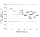
- FIG. 8 shows the product of the ratio of the easily breakable portion of carbon nanotubes, the exothermic peak temperature of differential thermal analysis and the crystallite size of the carbon nanotube (002) surface by X-ray diffraction and the geometric standard deviation of the fiber diameter distribution. Shows the relationship. These show a good correlation, and the smaller the product of the ratio between the exothermic peak temperature of differential thermal analysis and the crystallite size of the carbon nanotube (002) plane in X-ray diffraction and the geometric standard deviation of the fiber diameter distribution, the more the carbon nanotube Is easy to disperse, and the coating film resistance when the dispersion is used as a coating film also becomes low.
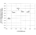
- FIG. 9 shows the relationship between the water vapor adsorption amount of carbon nanotubes having a tube outer diameter of 10 to 13 nm and the ultrasonic dispersion dynamic light scattering particle diameter (d50) / dynamic light scattering particle diameter (d50) with a stirrer.
- the ultrasonic dispersion dynamic light scattering particle diameter (d50) / dynamic light scattering particle diameter (d50) with a stirrer is small, that is, relatively to the water as a solvent.
- the dispersion of water is not sufficient, and the familiarity with water is also bad.
- Comparative Example 2 the familiarity with water is good, but the dispersibility is poor because the proportion of the easily fractured surface is small.
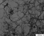
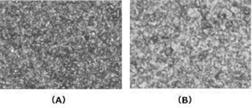
- FIG. 10 shows optical micrographs of the carbon nanotube coating films of Example 1 and Comparative Example 3. It can be confirmed that the photograph of Comparative Example 3 has a large constitutional unit and uneven dispersion. From Table 1, it can be confirmed that the resistance of Comparative Example 3 is low, but this is because the fiber diameter of the carbon nanotube is thin, and when the coating film is actually viewed, the dispersion is not sufficient.
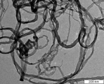
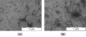
- FIG. 11 shows photographs of transmission microscopes of Example 4 and Comparative Example 3.
- the fiber diameter of the carbon nanotubes is narrower, but in Example 4, the fiber length of the carbon nanotubes is shorter and more dispersed. This is largely due to the ratio of easily breakable portions of the carbon nanotube.
- Comparative Example 4 and Comparative Example 5 in which the carbon nanotube fiber diameters were the same and the existence ratio of easily breakable portions was small, a coating film could not be formed.
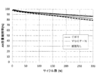
- FIG. 12 shows the cycle characteristics when the aqueous dispersion of carbon nanotubes of Example 1 is used as a conductive material on the negative electrode side of the lithium ion secondary battery.
- carbon nanofiber Showa Denko KK, VGCF-H, fiber diameter 130 nm
- the cycle characteristics of the carbon nanotubes of the present invention are extremely good. This is a result of sufficiently dispersing the carbon nanotubes without distorting the crystals because it is not necessary to give excessive energy for the dispersion.
- the sufficiently small fiber diameter with respect to the carbon nanofibers leads to improvement in cycle characteristics, and the carbon nanotube of the present invention is also suitable as a conductive material for a lithium ion secondary battery.
- the carbon nanotube according to the present invention has a constricted portion in the wall of the carbon nanotube, it is easy to cut, and although it is a carbon nanotube with a small diameter, it can be easily dispersed without giving excessive mechanical energy. It is also suitable for use in various fields such as semiconductor devices and as a material for power storage devices.
Priority Applications (5)
| Application Number | Priority Date | Filing Date | Title |
|---|---|---|---|
| KR1020177011731A KR102467230B1 (ko) | 2014-11-14 | 2015-11-12 | 카본 나노 튜브와 그의 제조 방법 및 카본 나노 튜브를 사용한 리튬 이온 이차 전지 |
| CN201580060300.1A CN107074546B (zh) | 2014-11-14 | 2015-11-12 | 碳纳米管及其制造方法、以及使用碳纳米管的锂离子二次电池 |
| JP2016559106A JP6642447B2 (ja) | 2014-11-14 | 2015-11-12 | カーボンナノチューブとその製造方法、及びカーボンナノチューブを用いたリチウムイオン二次電池 |
| EP15859876.3A EP3219669A4 (en) | 2014-11-14 | 2015-11-12 | Carbon nanotube and method for manufacturing same, and lithium ion secondary battery using carbon nanotube |
| US15/525,165 US10570016B2 (en) | 2014-11-14 | 2015-11-12 | Carbon nanotube and process for producing the carbon nanotube, and lithium ion secondary battery using the carbon nanotube |
Applications Claiming Priority (2)
| Application Number | Priority Date | Filing Date | Title |
|---|---|---|---|
| JP2014-232247 | 2014-11-14 | ||
| JP2014232247 | 2014-11-14 |
Publications (1)
| Publication Number | Publication Date |
|---|---|
| WO2016076393A1 true WO2016076393A1 (ja) | 2016-05-19 |
Family
ID=55954470
Family Applications (1)
| Application Number | Title | Priority Date | Filing Date |
|---|---|---|---|
| PCT/JP2015/081853 WO2016076393A1 (ja) | 2014-11-14 | 2015-11-12 | カーボンナノチューブとその製造方法、及びカーボンナノチューブを用いたリチウムイオン二次電池 |
Country Status (7)
| Country | Link |
|---|---|
| US (1) | US10570016B2 (ko) |
| EP (1) | EP3219669A4 (ko) |
| JP (1) | JP6642447B2 (ko) |
| KR (1) | KR102467230B1 (ko) |
| CN (1) | CN107074546B (ko) |
| TW (1) | TW201628715A (ko) |
| WO (1) | WO2016076393A1 (ko) |
Cited By (10)
| Publication number | Priority date | Publication date | Assignee | Title |
|---|---|---|---|---|
| WO2019188539A1 (ja) | 2018-03-29 | 2019-10-03 | 日産化学株式会社 | エネルギー貯蔵デバイスのアンダーコート層形成用組成物 |
| WO2019188558A1 (ja) | 2018-03-29 | 2019-10-03 | 日産化学株式会社 | エネルギー貯蔵デバイス用電極及びエネルギー貯蔵デバイス |
| WO2019188559A1 (ja) | 2018-03-29 | 2019-10-03 | 日産化学株式会社 | エネルギー貯蔵デバイス電極用アンダーコート箔 |
| WO2019188550A1 (ja) * | 2018-03-29 | 2019-10-03 | 日産化学株式会社 | エネルギー貯蔵デバイスのアンダーコート層形成用組成物 |
| WO2019188535A1 (ja) | 2018-03-29 | 2019-10-03 | 日産化学株式会社 | 導電性炭素材料分散液 |
| WO2019188556A1 (ja) | 2018-03-29 | 2019-10-03 | 日産化学株式会社 | エネルギー貯蔵デバイス用電極及びエネルギー貯蔵デバイス |
| WO2019188540A1 (ja) | 2018-03-29 | 2019-10-03 | 日産化学株式会社 | エネルギー貯蔵デバイスのアンダーコート層形成用組成物 |
| WO2019188537A1 (ja) | 2018-03-29 | 2019-10-03 | 日産化学株式会社 | エネルギー貯蔵デバイスのアンダーコート層形成用組成物 |
| WO2019188538A1 (ja) | 2018-03-29 | 2019-10-03 | 日産化学株式会社 | エネルギー貯蔵デバイスのアンダーコート層形成用組成物 |
| WO2020004095A1 (ja) * | 2018-06-28 | 2020-01-02 | 東洋インキScホールディングス株式会社 | カーボンナノチューブ分散液及びその利用 |
Families Citing this family (3)
| Publication number | Priority date | Publication date | Assignee | Title |
|---|---|---|---|---|
| KR102475709B1 (ko) * | 2019-03-07 | 2022-12-09 | 주식회사 엘지에너지솔루션 | 탄소나노튜브, 상기 탄소나노튜브를 포함하는 전극 및 이차 전지 |
| CN111455339B (zh) * | 2020-05-22 | 2022-07-01 | 厦门市计量检定测试院 | 用于高吸收比材料的垂直碳纳米管阵列的制备方法 |
| CN112290021B (zh) * | 2020-09-28 | 2022-09-06 | 合肥国轩高科动力能源有限公司 | 一种锂离子电池用碳纳米管导电剂的制备方法 |
Citations (5)
| Publication number | Priority date | Publication date | Assignee | Title |
|---|---|---|---|---|
| JP2006169072A (ja) * | 2004-12-17 | 2006-06-29 | Toyota Motor Corp | 筒状炭素構造体及びその製造方法、並びに、ガス吸蔵材料、複合材料及びその強化方法、摺動材料、フィールドエミッション、表面分析装置、塗装材料 |
| JP2009155127A (ja) * | 2007-12-25 | 2009-07-16 | Sonac Kk | カーボンナノチューブおよび該カーボンナノチューブの製造方法 |
| JP2010018833A (ja) * | 2008-07-10 | 2010-01-28 | Daido Steel Co Ltd | フラックス供給装置 |
| JP2013519515A (ja) * | 2010-02-16 | 2013-05-30 | バイエル・インテレクチュアル・プロパティ・ゲゼルシャフト・ミット・ベシュレンクテル・ハフツング | カーボンナノチューブの製造 |
| JP2014203804A (ja) * | 2013-04-10 | 2014-10-27 | 日本ゼオン株式会社 | リチウムイオン二次電池用正極およびリチウムイオン二次電池 |
Family Cites Families (13)
| Publication number | Priority date | Publication date | Assignee | Title |
|---|---|---|---|---|
| JPS58180615A (ja) | 1982-04-10 | 1983-10-22 | Morinobu Endo | 気相法による炭素繊維の製造方法 |
| JP2003238126A (ja) | 2002-02-14 | 2003-08-27 | Toray Ind Inc | カーボンナノチューブの親水性分散液およびその製造方法 |
| JP2004276232A (ja) | 2003-02-24 | 2004-10-07 | Mitsubishi Electric Corp | カーボンナノチューブ分散液およびその製造方法 |
| CN1588679A (zh) * | 2004-08-09 | 2005-03-02 | 深圳市纳米港有限公司 | 锂离子二次电池正极材料及其制备方法 |
| KR20070084288A (ko) | 2004-10-22 | 2007-08-24 | 하이페리온 커탤리시스 인터내셔널 인코포레이티드 | 탄소 나노튜브의 개선된 오존첨가분해 방법 |
| CN1326267C (zh) * | 2005-05-27 | 2007-07-11 | 深圳市贝特瑞电子材料有限公司 | 锂离子电池复合碳负极材料及其制备方法 |
| JP4747295B2 (ja) * | 2005-06-02 | 2011-08-17 | 国立大学法人信州大学 | 同軸カーボンナノチューブシートの製造方法 |
| JP5266907B2 (ja) * | 2007-06-29 | 2013-08-21 | 東レ株式会社 | カーボンナノチューブ集合体、分散体および導電性フィルム |
| WO2009069344A1 (ja) * | 2007-11-30 | 2009-06-04 | Toray Industries, Inc. | カーボンナノチューブ集合体およびその製造方法 |
| KR100976174B1 (ko) * | 2009-02-13 | 2010-08-16 | 금호석유화학 주식회사 | 얇은 다중벽 탄소나노튜브 제조용 촉매조성물 및 이의 제조방법 |
| CN102341345B (zh) * | 2009-03-04 | 2014-03-12 | 东丽株式会社 | 含碳纳米管组合物、碳纳米管制造用催化剂体和碳纳米管水性分散液 |
| JP5110059B2 (ja) | 2009-09-07 | 2012-12-26 | 宇部興産株式会社 | 微細な炭素繊維および微細な炭素短繊維 |
| JPWO2014115560A1 (ja) * | 2013-01-24 | 2017-01-26 | 日本ゼオン株式会社 | カーボンナノチューブ分散液及びその製造方法、並びにカーボンナノチューブ組成物及びその製造方法 |
-
2015
- 2015-11-12 WO PCT/JP2015/081853 patent/WO2016076393A1/ja active Application Filing
- 2015-11-12 CN CN201580060300.1A patent/CN107074546B/zh active Active
- 2015-11-12 JP JP2016559106A patent/JP6642447B2/ja active Active
- 2015-11-12 US US15/525,165 patent/US10570016B2/en active Active
- 2015-11-12 KR KR1020177011731A patent/KR102467230B1/ko active IP Right Grant
- 2015-11-12 EP EP15859876.3A patent/EP3219669A4/en active Pending
- 2015-11-13 TW TW104137549A patent/TW201628715A/zh unknown
Patent Citations (5)
| Publication number | Priority date | Publication date | Assignee | Title |
|---|---|---|---|---|
| JP2006169072A (ja) * | 2004-12-17 | 2006-06-29 | Toyota Motor Corp | 筒状炭素構造体及びその製造方法、並びに、ガス吸蔵材料、複合材料及びその強化方法、摺動材料、フィールドエミッション、表面分析装置、塗装材料 |
| JP2009155127A (ja) * | 2007-12-25 | 2009-07-16 | Sonac Kk | カーボンナノチューブおよび該カーボンナノチューブの製造方法 |
| JP2010018833A (ja) * | 2008-07-10 | 2010-01-28 | Daido Steel Co Ltd | フラックス供給装置 |
| JP2013519515A (ja) * | 2010-02-16 | 2013-05-30 | バイエル・インテレクチュアル・プロパティ・ゲゼルシャフト・ミット・ベシュレンクテル・ハフツング | カーボンナノチューブの製造 |
| JP2014203804A (ja) * | 2013-04-10 | 2014-10-27 | 日本ゼオン株式会社 | リチウムイオン二次電池用正極およびリチウムイオン二次電池 |
Non-Patent Citations (1)
| Title |
|---|
| See also references of EP3219669A4 * |
Cited By (21)
| Publication number | Priority date | Publication date | Assignee | Title |
|---|---|---|---|---|
| US20210020952A1 (en) * | 2018-03-29 | 2021-01-21 | Nissan Chemical Corporation | Undercoat layer-forming composition for energy storage device |
| WO2019188535A1 (ja) | 2018-03-29 | 2019-10-03 | 日産化学株式会社 | 導電性炭素材料分散液 |
| WO2019188539A1 (ja) | 2018-03-29 | 2019-10-03 | 日産化学株式会社 | エネルギー貯蔵デバイスのアンダーコート層形成用組成物 |
| JP7318637B2 (ja) | 2018-03-29 | 2023-08-01 | 日産化学株式会社 | エネルギー貯蔵デバイスのアンダーコート層形成用組成物 |
| US20210028463A1 (en) * | 2018-03-29 | 2021-01-28 | Nissan Chemical Corporation | Undercoat layer-forming composition for energy storage device |
| WO2019188556A1 (ja) | 2018-03-29 | 2019-10-03 | 日産化学株式会社 | エネルギー貯蔵デバイス用電極及びエネルギー貯蔵デバイス |
| WO2019188540A1 (ja) | 2018-03-29 | 2019-10-03 | 日産化学株式会社 | エネルギー貯蔵デバイスのアンダーコート層形成用組成物 |
| WO2019188537A1 (ja) | 2018-03-29 | 2019-10-03 | 日産化学株式会社 | エネルギー貯蔵デバイスのアンダーコート層形成用組成物 |
| WO2019188538A1 (ja) | 2018-03-29 | 2019-10-03 | 日産化学株式会社 | エネルギー貯蔵デバイスのアンダーコート層形成用組成物 |
| JP7318638B2 (ja) | 2018-03-29 | 2023-08-01 | 日産化学株式会社 | エネルギー貯蔵デバイスのアンダーコート層形成用組成物 |
| WO2019188559A1 (ja) | 2018-03-29 | 2019-10-03 | 日産化学株式会社 | エネルギー貯蔵デバイス電極用アンダーコート箔 |
| WO2019188558A1 (ja) | 2018-03-29 | 2019-10-03 | 日産化学株式会社 | エネルギー貯蔵デバイス用電極及びエネルギー貯蔵デバイス |
| WO2019188550A1 (ja) * | 2018-03-29 | 2019-10-03 | 日産化学株式会社 | エネルギー貯蔵デバイスのアンダーコート層形成用組成物 |
| JPWO2019188538A1 (ja) * | 2018-03-29 | 2021-04-08 | 日産化学株式会社 | エネルギー貯蔵デバイスのアンダーコート層形成用組成物 |
| JPWO2019188537A1 (ja) * | 2018-03-29 | 2021-04-08 | 日産化学株式会社 | エネルギー貯蔵デバイスのアンダーコート層形成用組成物 |
| KR20230058188A (ko) * | 2018-06-28 | 2023-05-02 | 토요잉크Sc홀딩스주식회사 | 카본나노튜브 분산액 및 그의 이용 |
| KR102528285B1 (ko) | 2018-06-28 | 2023-05-03 | 토요잉크Sc홀딩스주식회사 | 카본나노튜브 분산액 및 그의 이용 |
| KR102545011B1 (ko) | 2018-06-28 | 2023-06-20 | 토요잉크Sc홀딩스주식회사 | 카본나노튜브 분산액 및 그의 이용 |
| WO2020004095A1 (ja) * | 2018-06-28 | 2020-01-02 | 東洋インキScホールディングス株式会社 | カーボンナノチューブ分散液及びその利用 |
| KR20210013224A (ko) * | 2018-06-28 | 2021-02-03 | 토요잉크Sc홀딩스주식회사 | 카본나노튜브 분산액 및 그의 이용 |
| US11923546B2 (en) | 2018-06-28 | 2024-03-05 | Toyo Ink Sc Holdings Co., Ltd. | Carbon nanotube dispersion and use thereof |
Also Published As
| Publication number | Publication date |
|---|---|
| EP3219669A4 (en) | 2018-07-25 |
| JP6642447B2 (ja) | 2020-02-05 |
| TW201628715A (zh) | 2016-08-16 |
| US20170313586A1 (en) | 2017-11-02 |
| CN107074546B (zh) | 2019-06-21 |
| US10570016B2 (en) | 2020-02-25 |
| JPWO2016076393A1 (ja) | 2017-08-31 |
| CN107074546A (zh) | 2017-08-18 |
| KR20170084050A (ko) | 2017-07-19 |
| EP3219669A1 (en) | 2017-09-20 |
| KR102467230B1 (ko) | 2022-11-16 |
Similar Documents
| Publication | Publication Date | Title |
|---|---|---|
| WO2016076393A1 (ja) | カーボンナノチューブとその製造方法、及びカーボンナノチューブを用いたリチウムイオン二次電池 | |
| Nzereogu et al. | Anode materials for lithium-ion batteries: A review | |
| US11631838B2 (en) | Graphene-enhanced anode particulates for lithium ion batteries | |
| Kamali | Eco-friendly production of high quality low cost graphene and its application in lithium ion batteries | |
| Cong et al. | Characteristics and electrochemical performances of silicon/carbon nanofiber/graphene composite films as anode materials for binder-free lithium-ion batteries | |
| Pham et al. | Liquid phase co-exfoliated MoS2–graphene composites as anode materials for lithium ion batteries | |
| Li et al. | In situ sol-gel synthesis of ultrafine ZnO nanocrystals anchored on graphene as anode material for lithium-ion batteries | |
| Wang et al. | Fast lithium-ion insertion of TiO2 nanotube and graphene composites | |
| KR101393651B1 (ko) | 리튬 이차전지용 양극 활 물질, 그 제조방법 및 이를 포함하는 리튬 이차전지 | |
| Chen et al. | Electrochemical lithiation and de-lithiation of carbon nanotube-Sn2Sb nanocomposites | |
| Mendoza-Sánchez et al. | A study of the charge storage properties of a MoSe2 nanoplatelets/SWCNTs electrode in a Li-ion based electrolyte | |
| JP6767668B2 (ja) | カーボンナノチューブ分散液 | |
| Xue et al. | Enhanced electrochemical performance of ZnMoO4/reduced graphene oxide composites as anode materials for lithium-ion batteries | |
| EP3512012B1 (en) | Conductive composition for electrodes, and electrode and battery using same | |
| EP4050679A1 (en) | Carbon nanotube dispersion liquid for nonaqueous electrolyte secondary battery, resin composition using same, mixture slurry, membrane electrode, and nonaqueous electrolyte secondary battery | |
| WO2004011370A1 (ja) | 複合黒鉛材料およびその製造方法、ならびにこれを用いた負極材料、負極およびリチウムイオン二次電池 | |
| JP2017142997A (ja) | ニッケル酸リチウム−炭素複合体正極活物質粒子粉末及びその製造方法、並びに非水電解質二次電池 | |
| KR20230034966A (ko) | 카본나노튜브, 카본나노튜브 분산액, 그것을 이용한 비수전해질 이차전지 | |
| JPWO2017082338A1 (ja) | 鉄酸化物−炭素複合体粒子粉末及びその製造方法 | |
| Assresahegn et al. | Graphene nanosheets and polyacrylic acid grafted silicon composite anode for lithium ion batteries | |
| Li et al. | Self-assembly of antimony sulfide nanowires on three-dimensional reduced GO with superior electrochemical lithium storage performances | |
| Shan et al. | Carbon nanotubes cross-linked Zn 2 SnO 4 nanoparticles/graphene networks as high capacities, long life anode materials for lithium ion batteries | |
| Xie et al. | One-pot hydrothermal fabrication and enhanced lithium storage capability of SnO 2 nanorods intertangled with carbon nanotubes and graphene nanosheets | |
| Zhu et al. | A facial solvothermal reduction route for the production of Li4Ti5O12/graphene composites with enhanced electrochemical performance | |
| WO2020213628A1 (ja) | 複合炭素粒子、その製造方法及びその用途 |
Legal Events
| Date | Code | Title | Description |
|---|---|---|---|
| 121 | Ep: the epo has been informed by wipo that ep was designated in this application |
Ref document number: 15859876 Country of ref document: EP Kind code of ref document: A1 |
|
| ENP | Entry into the national phase |
Ref document number: 2016559106 Country of ref document: JP Kind code of ref document: A |
|
| ENP | Entry into the national phase |
Ref document number: 20177011731 Country of ref document: KR Kind code of ref document: A |
|
| REEP | Request for entry into the european phase |
Ref document number: 2015859876 Country of ref document: EP |
|
| WWE | Wipo information: entry into national phase |
Ref document number: 15525165 Country of ref document: US |
|
| NENP | Non-entry into the national phase |
Ref country code: DE |