WO2016072196A1 - Dispositif de manipulation - Google Patents
Dispositif de manipulation Download PDFInfo
- Publication number
- WO2016072196A1 WO2016072196A1 PCT/JP2015/078287 JP2015078287W WO2016072196A1 WO 2016072196 A1 WO2016072196 A1 WO 2016072196A1 JP 2015078287 W JP2015078287 W JP 2015078287W WO 2016072196 A1 WO2016072196 A1 WO 2016072196A1
- Authority
- WO
- WIPO (PCT)
- Prior art keywords
- moving member
- motor
- operating device
- moving
- guide shaft
- Prior art date
Links
Images


Classifications
-
- G—PHYSICS
- G05—CONTROLLING; REGULATING
- G05G—CONTROL DEVICES OR SYSTEMS INSOFAR AS CHARACTERISED BY MECHANICAL FEATURES ONLY
- G05G5/00—Means for preventing, limiting or returning the movements of parts of a control mechanism, e.g. locking controlling member
- G05G5/03—Means for enhancing the operator's awareness of arrival of the controlling member at a command or datum position; Providing feel, e.g. means for creating a counterforce
-
- A—HUMAN NECESSITIES
- A63—SPORTS; GAMES; AMUSEMENTS
- A63F—CARD, BOARD, OR ROULETTE GAMES; INDOOR GAMES USING SMALL MOVING PLAYING BODIES; VIDEO GAMES; GAMES NOT OTHERWISE PROVIDED FOR
- A63F13/00—Video games, i.e. games using an electronically generated display having two or more dimensions
- A63F13/20—Input arrangements for video game devices
- A63F13/24—Constructional details thereof, e.g. game controllers with detachable joystick handles
-
- A—HUMAN NECESSITIES
- A63—SPORTS; GAMES; AMUSEMENTS
- A63F—CARD, BOARD, OR ROULETTE GAMES; INDOOR GAMES USING SMALL MOVING PLAYING BODIES; VIDEO GAMES; GAMES NOT OTHERWISE PROVIDED FOR
- A63F13/00—Video games, i.e. games using an electronically generated display having two or more dimensions
- A63F13/25—Output arrangements for video game devices
- A63F13/28—Output arrangements for video game devices responding to control signals received from the game device for affecting ambient conditions, e.g. for vibrating players' seats, activating scent dispensers or affecting temperature or light
- A63F13/285—Generating tactile feedback signals via the game input device, e.g. force feedback
-
- F—MECHANICAL ENGINEERING; LIGHTING; HEATING; WEAPONS; BLASTING
- F16—ENGINEERING ELEMENTS AND UNITS; GENERAL MEASURES FOR PRODUCING AND MAINTAINING EFFECTIVE FUNCTIONING OF MACHINES OR INSTALLATIONS; THERMAL INSULATION IN GENERAL
- F16H—GEARING
- F16H19/00—Gearings comprising essentially only toothed gears or friction members and not capable of conveying indefinitely-continuing rotary motion
- F16H19/02—Gearings comprising essentially only toothed gears or friction members and not capable of conveying indefinitely-continuing rotary motion for interconverting rotary or oscillating motion and reciprocating motion
- F16H19/04—Gearings comprising essentially only toothed gears or friction members and not capable of conveying indefinitely-continuing rotary motion for interconverting rotary or oscillating motion and reciprocating motion comprising a rack
-
- G—PHYSICS
- G06—COMPUTING; CALCULATING OR COUNTING
- G06F—ELECTRIC DIGITAL DATA PROCESSING
- G06F3/00—Input arrangements for transferring data to be processed into a form capable of being handled by the computer; Output arrangements for transferring data from processing unit to output unit, e.g. interface arrangements
- G06F3/01—Input arrangements or combined input and output arrangements for interaction between user and computer
- G06F3/016—Input arrangements with force or tactile feedback as computer generated output to the user
-
- G—PHYSICS
- G06—COMPUTING; CALCULATING OR COUNTING
- G06F—ELECTRIC DIGITAL DATA PROCESSING
- G06F3/00—Input arrangements for transferring data to be processed into a form capable of being handled by the computer; Output arrangements for transferring data from processing unit to output unit, e.g. interface arrangements
- G06F3/01—Input arrangements or combined input and output arrangements for interaction between user and computer
- G06F3/02—Input arrangements using manually operated switches, e.g. using keyboards or dials
- G06F3/0202—Constructional details or processes of manufacture of the input device
-
- G—PHYSICS
- G06—COMPUTING; CALCULATING OR COUNTING
- G06F—ELECTRIC DIGITAL DATA PROCESSING
- G06F3/00—Input arrangements for transferring data to be processed into a form capable of being handled by the computer; Output arrangements for transferring data from processing unit to output unit, e.g. interface arrangements
- G06F3/01—Input arrangements or combined input and output arrangements for interaction between user and computer
- G06F3/03—Arrangements for converting the position or the displacement of a member into a coded form
- G06F3/033—Pointing devices displaced or positioned by the user, e.g. mice, trackballs, pens or joysticks; Accessories therefor
- G06F3/0362—Pointing devices displaced or positioned by the user, e.g. mice, trackballs, pens or joysticks; Accessories therefor with detection of 1D translations or rotations of an operating part of the device, e.g. scroll wheels, sliders, knobs, rollers or belts
-
- H—ELECTRICITY
- H02—GENERATION; CONVERSION OR DISTRIBUTION OF ELECTRIC POWER
- H02K—DYNAMO-ELECTRIC MACHINES
- H02K11/00—Structural association of dynamo-electric machines with electric components or with devices for shielding, monitoring or protection
- H02K11/20—Structural association of dynamo-electric machines with electric components or with devices for shielding, monitoring or protection for measuring, monitoring, testing, protecting or switching
- H02K11/21—Devices for sensing speed or position, or actuated thereby
-
- H—ELECTRICITY
- H02—GENERATION; CONVERSION OR DISTRIBUTION OF ELECTRIC POWER
- H02K—DYNAMO-ELECTRIC MACHINES
- H02K7/00—Arrangements for handling mechanical energy structurally associated with dynamo-electric machines, e.g. structural association with mechanical driving motors or auxiliary dynamo-electric machines
- H02K7/06—Means for converting reciprocating motion into rotary motion or vice versa
-
- H—ELECTRICITY
- H02—GENERATION; CONVERSION OR DISTRIBUTION OF ELECTRIC POWER
- H02K—DYNAMO-ELECTRIC MACHINES
- H02K7/00—Arrangements for handling mechanical energy structurally associated with dynamo-electric machines, e.g. structural association with mechanical driving motors or auxiliary dynamo-electric machines
- H02K7/10—Structural association with clutches, brakes, gears, pulleys or mechanical starters
- H02K7/116—Structural association with clutches, brakes, gears, pulleys or mechanical starters with gears
-
- G—PHYSICS
- G05—CONTROLLING; REGULATING
- G05G—CONTROL DEVICES OR SYSTEMS INSOFAR AS CHARACTERISED BY MECHANICAL FEATURES ONLY
- G05G1/00—Controlling members, e.g. knobs or handles; Assemblies or arrangements thereof; Indicating position of controlling members
- G05G1/02—Controlling members for hand actuation by linear movement, e.g. push buttons
Definitions
- the present invention relates to an operating device that presses an operating portion with a hand, and particularly to an operating device that can control a reaction force acting on the operating portion in accordance with an operating position of the operating portion.
- An operating device to which a reaction force is applied when operating the operating unit is widely used as a controller for a game device.
- Patent Document 1 describes an invention relating to a gun unit used in a shooting game device as a controller for a game device.
- a gun body is attached to an upper portion of a support portion, and the gun body is provided with a vibration mechanism that reciprocally vibrates the entire body back and forth.
- the vibration mechanism is started, and the vibration of the front and rear is given to the whole gun body, and the reaction is transmitted to the hand of the game operator.
- Patent Document 1 gives a reciprocating motion back and forth with respect to the entire gun body, and does not directly give a reaction feel to the finger operating the trigger. It is difficult to perform certain game operations. Further, since the reaction force applied to the gun body is limited to the vibration force caused by the rotation of the motor, it is impossible to apply various operation reaction forces to the operator.
- the vibration applied to the entire gun will not be transmitted to the trigger, and it will be difficult to realize a realistic game operation.
- the present invention solves the above-described conventional problems, can apply a reaction force to a finger operating the operation unit, and can apply various reaction forces according to the operation position of the operation unit.
- An object of the present invention is to provide an operating device that can be provided.
- the present invention adopts a guide structure that suppresses rattling of the operation unit, thereby making the operation smooth and allowing the reaction force to feel directly acting on the operation unit. It aims at providing a simple operation device.
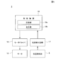
- the present invention includes a chassis, a moving member supported by the chassis, an operation unit that applies a moving force to the moving member, a motor that applies a force to the moving member, and a position detection unit that detects the position of the moving member. And a control device that controls the output of the motor in response to a detection signal from the position detection unit,
- the chassis is provided with a guide shaft and a sliding guide portion in parallel with each other, the moving member is provided with a bearing portion and a sliding portion, the guide shaft is inserted into the bearing portion, and the sliding portion is provided.
- the moving part slides on the sliding guide part, and the moving member is supported so as to be reciprocally movable in the axial direction of the guide shaft.
- the operating reaction force can be directly felt by the hand or finger operating the moving member. Further, since the moving position of the moving member can be detected and various forces can be applied to the moving member, various operation feelings can be given to the operation unit.
- the guide shaft is provided in the chassis and the bearing portion of the moving member reciprocates along the guide shaft, it is easy to suppress rattling during the movement of the moving member, and the pressing of the operation portion The operation can be performed smoothly. In addition, it becomes easy to apply an operation reaction force directly to a finger or a hand that operates the operation unit.
- the operation device of the present invention is provided with a pinion gear that is rotationally driven by the motor, and the moving member is formed with a rack portion that meshes with the pinion gear,
- the rack portion has the guide shaft in the vertical direction. What is arrange
- the moving force acting on the rack portion can be superimposed on the axis of the guide shaft, the moving force can be applied directly to the moving member, and the moving member can be moved by the moving force. Unnecessary moment applied to the motor can be minimized, and a stable reaction force can be applied from the motor to the moving member and the operation unit.
- the moving member is provided with a thick portion and a recess formed on a side of the thick portion, and the bearing portion and the rack portion are provided on the thick portion. Are preferably formed.
- a speed reduction mechanism for transmitting power from the motor to the pinion gear is provided, and the speed reduction mechanism can face the recess of the moving member.
- the motor may be provided at a position facing the concave portion of the moving member.
- the tooth part of the pinion gear and the tooth part of the rack part are helical teeth.
- the transmission of the mutual force between the moving member and the pinion gear becomes smooth, the operation portion is easy to operate, and the motor power A reaction force can be effectively applied to the operation unit.
- the chassis is formed of a metal plate, and an opposing wall portion facing the moving direction of the moving member and a side wall portion extending in parallel with the moving direction of the moving member are bent.
- the guide shaft may be fixed vertically to the opposing wall portion, and the sliding guide portion may be provided on the side wall portion.
- the chassis is made of sheet metal material, it can be made small and lightweight. Further, since the moving member moves back and forth with respect to the guide shaft, the opposing wall portion to which the guide shaft is fixed and the side wall portion on which the sliding guide portion is formed are bent, and mutual dimensional accuracy is obtained. Even if it is slightly rough, the moving member can be moved back and forth with high accuracy without causing rattling.
- the operating reaction force can be directly felt by the hand or finger operating the moving member. Further, since the moving position of the moving member can be detected and various forces can be applied to the moving member, various operation feelings can be given to the operation unit.
- the guide shaft is provided in the chassis and the bearing portion of the moving member reciprocates along the guide shaft, it is easy to suppress rattling during the movement of the moving member, and the pressing of the operation portion The operation can be performed smoothly. In addition, it becomes easy to apply an operation reaction force directly to a finger or a hand that operates the operation unit.
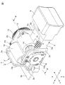
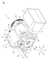
- FIG. 1 It is a perspective view which shows the whole structure of the operating device which concerns on the 1st Embodiment of this invention, and shows the state which the moving member and the operation part advanced, It is a perspective view which shows the whole structure of the operating device which concerns on the 1st Embodiment of this invention, and shows the state which the moving member and the operation part retracted,
- FIG. 1 to 7 show an example in which the operating device according to the embodiment of the present invention is mounted on a gun-type controller for a shooting game.
- the operating device of the present invention can be mounted on various controllers other than the gun-type controller and various devices other than games.
- the X direction is the horizontal direction
- the Y direction is the front-rear direction
- the Z direction is the vertical direction.
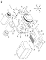
- the operating device 1 has a chassis 4.
- the chassis 4 includes a main body frame 2 and a bracket 3 for fixing the main body frame inside the gun-type controller. Both the main body frame 2 and the bracket 3 are made of a sheet metal material.
- the main body frame 2 includes an opposing wall portion 2a, and a first side wall portion 2b and a second side wall portion 2c that are bent at right angles from both sides of the opposing wall portion 2a.
- the bracket 3 is formed by bending a fixing piece 3a and a mounting piece 3b at a right angle.
- the opposing wall 2a of the main body frame 2 and the fixed piece 3a of the bracket 3 are fixed to each other by spot welding or the like.
- a mounting hole 3c is formed in the mounting piece 3b, and the operating device 1 is fixed inside the gun-type controller by a mounting screw inserted into the mounting hole 3c.
- the moving member 5 is provided inside the main body frame.
- the moving member 5 is made of a synthetic resin material.
- a thick part 5a and a thin part 5b are integrally formed, and a concave part 5c is formed in the upper part of the thin part 5b in the vertical direction.
- the thick part 5a and the thin part 5b are formed by being divided in the horizontal direction (X direction).
- a bearing portion 5 c is formed on the thick portion 5 a of the moving member 5.
- the bearing portion 5c is a bearing groove released downward, and is formed continuously in the front-rear direction (Y direction).
- a sliding portion 5d is integrally formed at the side end of the thin portion 5b.
- the center of the bearing part 5c and the center of the sliding part 5d are arranged at an interval in the horizontal direction (X direction).
- a recess 5e is formed between the thick part 5a and the thin part 5b and is released toward the rear (Y2 direction).
- the spring guide shaft 5f is integrally formed.
- the spring guide shaft 5f extends linearly in the front-rear direction (Y direction).
- a guide shaft 6 is fixed to the opposing wall portion 2a of the main body frame 2 constituting a part of the chassis 4.
- the guide shaft 6 is made of metal, is vertically attached to the opposing wall portion 2a, and extends in the front-rear direction (Y direction).
- a sliding guide portion 7 is formed on the first side wall portion 2 b of the main body frame 2.
- the sliding guide portion 7 is a guide slot that extends linearly in the front-rear direction (Y direction).
- the shaft center Os of the guide shaft 6 and the guide center line Og of the sliding guide portion 7 face each other in parallel with an interval in the horizontal direction (X direction).
- the guide shaft 6 is inserted into the bearing portion 5 c, the sliding portion 5 d is slidably inserted into the sliding guide portion 7, and the moving member 5 is moved in the front-rear direction inside the main body frame 2. It is supported so as to be movable in the (Y direction).
- the bearing portion 5c is slidably inserted in the horizontal direction (X direction) with respect to the guide shaft 6 with almost no gap, and the moving member 5 is movable in the front-rear direction based on the axis Os of the guide shaft 6.
- the sliding portion 5d is inserted in the sliding guide portion 7 in the vertical direction (Z direction) with almost no gap.
- the fitting of the sliding portion 5d and the sliding guide portion 7 causes the shaft of the moving member 5 to move. Shaking in the rotation direction around the core Os is restricted.
- a compression coil spring 8 is mounted on the outer periphery of the spring guide shaft 5f of the moving member 5.
- the compression coil spring 8 is interposed between the moving member 5 and the opposing wall portion 2a in a contracted state.
- the moving member 5 is always urged forward (Y1 direction) by the elastic force of the compression coil spring 8.
- a fitting portion 5g is formed at the front (Y1 side) end of the moving member 5.
- This fitting part 5g is a T-shaped fitting protrusion.
- the operation portion 9 is formed of a synthetic resin material, and a fitting portion is formed at the rear end portion.
- This fitting part is a fitting recessed part.
- the fitting portion of the operation portion 9 is positioned by being concavo-convexly fitted to the fitting portion 5g of the moving member 5, and the operation portion 9 and the moving member 5 are fixed by screwing or the like. Since the operation unit 9 is detachable from the moving member 5, the operation unit 9 can be selected and attached according to the design of the controller to which the operation device 1 is mounted.
- the motor 10 is disposed between the first side wall 2b and the second side wall 2c of the main body frame 2, and the motor 10 is fixed to the main body frame 2 with screws.
- An output gear 11 is fixed to the output shaft of the motor 10.
- a reduction gear 12 is rotatably supported on the first side wall portion 2 b of the main body frame 2, and when the motor 10 is fixed to the main body frame 2, the output gear 11 meshes with the reduction gear 12.
- a gear box 13 is disposed between the first side wall 2b and the second side wall 2c of the main body frame 2. Mounting holes 13a and 13a are formed in the gear box 13, and mounting screws are inserted into the mounting holes 13a and 13a and screwed into the first side wall 2b, so that the gear box 13 is inserted into the first side wall 2b. It is fixed.
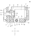
- a reduction mechanism is housed inside the gear box 13. As shown in FIG. 4, a reduction output shaft 13b protrudes from the gear box 13, and the rotational force of the reduction gear 12 is reduced by a reduction mechanism in the gear box 13 and transmitted to the reduction output shaft 13b.
- the speed reduction mechanism includes a sun gear and a planetary gear.
- a pinion gear 14 is fixed to the reduction output shaft 13b, and the rotational force of the motor 10 is reduced by the reduction gear 12 and the reduction mechanism in the gear box 13 and transmitted to the pinion gear 14.
- a rack portion 15 is formed on the upper surface of the thick portion 5a of the moving member 5, and the pinion gear 14 and the rack portion 15 are engaged with each other. Both the tooth part of the pinion gear 14 and the tooth part of the rack part 15 are helical teeth.
- the moving member 5 is formed with a thick portion 5a in a portion biased to one side in the horizontal direction (X direction), and a bearing portion 5c and a rack portion 15 are formed in the thick portion 5a. Therefore, a portion other than the thick portion 5a can be made thin.
- the rack portion 15 and the axis Os of the guide shaft 6 are arranged so as to overlap in the vertical direction (Z direction). That is, a part of the tooth portion of the rack portion 15 is located immediately above the axis Os.
- the position detector 16 is provided on the second side wall 2c of the main body frame 2.
- the position detection unit 16 includes a detection case 16a fixed to the second side wall 2c, a stator unit fixed to the detection case 16a, and a rotor unit that rotates within the detection case 16a.
- a rotor shaft 16b is fixed to the rotor portion. As shown in FIG. 4, the rotor shaft 16 b is fitted to the pinion gear 14, and the rotor shaft 16 b and the rotor portion rotate together with the pinion gear 14.
- the position detection unit 16 is a magnetic detection type encoder, a rotating magnet is fixed to the rotor unit, a magnetic detection element such as a GMR element is provided in the stator unit, and the rotation angle between the rotor shaft 16b and the rotor unit is a magnetic detection element. Detected by.
- the position detection unit 16 may be a resistance change type or optical type encoder.
- the position detection unit 16 is provided in the power transmission path from the output shaft of the motor 10 to the rack 3 d, but the position of the linear detection method is between the moving member 5 and the main body frame 2.
- a detection unit may be provided.
- the position detector 16 is preferably capable of detecting an absolute angle based on any rotational phase. Thereby, when the power source of the controller device 1 is cut off and then energized, it is possible to grasp at which point in the front-rear direction the moving member 5 is stopped.
- the controller device 1 has a control device 19.
- the control device 19 controls a shooting game, and is incorporated in a game machine body, a personal computer, a general-purpose information processing device, or the like.
- the control device 15 is composed mainly of a CPU (Central Processing Unit) and a storage unit 19a. When a shooting game is performed, game software is called from the storage unit 19a, and a game processing operation is performed according to a predetermined program.
- the control device 19 includes a display unit 19b such as a color liquid crystal panel and a speaker.
- the detection output detected by the position detection unit 16 is detected by the position detection circuit 17 and given to the control device 19.
- a control signal is given from the control device 19 to the motor driver 18 to control the motor 10.
- a control signal for driving the motor driver 18 is incorporated in a part of the game software.
- the operating device 1 can move the moving member 5 to an arbitrary position by giving a control command from the control device 19 to the motor driver 18 and starting the motor 10. For example, as shown in FIG. 1, the moving member 5 can be stopped at a position advanced in the Y1 direction, and as shown in FIG. 2, it can be stopped at a position retracted in the Y2 direction.
- the initial position of the moving member 5 can be set at any position according to the control flow executed by the control device 19.
- the moving member 5 is moved backward as shown in FIG. 2, and when the controller device 1 is turned on, the motor 10 is started and the movable member 5 is It is possible to move forward to the position shown in FIG.
- the moving member 5 When the moving member 5 is set to the initial position shown in FIG. 1, when the operation unit 9 is pushed backward (Y2 direction) by a finger or a hand, the backward movement of the moving member 5 is detected by the position detection unit 16. The backward distance is calculated by the position detection circuit 17 and notified to the control device 19. In the control device 19, when the moving member 5 moves backward, a command for giving an operation reaction force is notified to the motor driver 18 and the motor 10 operates. In the control device 19, in order to determine what operation reaction force should be applied based on the flow being processed when the operation unit 9 is pushed and operated, and to provide an appropriate operation reaction force at that time The drive pattern is given to the motor driver 18.
- This drive pattern determines how much the moving distance of the moving member 5 in the Y2 direction is allowed when the moving member 5 is pressed with a finger or hand based on the control flow at that time.
- the moving member 5 can be moved backward by 5 mm and a moving reaction force can be applied from the motor 10 to the moving member 5 so that the moving member 5 does not move back further, or the moving member 5 is moved back to 10 mm and then moved back further. You can make it impossible. This is to apply a braking force to the rotor of the motor 10 when the moving member 5 moves to a predetermined position, or to apply a moving force in the Y1 direction to prevent the moving member 5 from moving in the Y1 direction. Done in
- the force required to move the moving member 5 in the Y2 direction can be changed.
- the moving member 5 can be prevented from moving in the Y2 direction unless the operation unit 9 is pressed with a strong force with a finger or hand, or can be moved back to a predetermined distance of 5 mm or 10 mm with a relatively light force. It is also possible to do.
- the power torque of the motor 10 may be zero.
- the operation unit 9 is pushed in with a finger or hand in a state where the power torque of the motor 10 is zero, only the reaction force by the speed reduction mechanism and the compression coil spring 8 is applied to the finger or hand pushing the operation unit 9.
- the moving member 5 is moved to the end in the Y2 direction.
- the moving member 5 when the moving torque of the motor 10 is reduced to zero while the moving member 5 is stopped at any position, the moving member 5 is pushed in the Y1 direction by the elastic force of the compression coil spring 8, and the operation unit 9 may be set to the initial position shown in FIG.
- the torque of the motor 10 can be changed to make the finger or hand pushing the operation unit 9 feel vibration.
- the moving member 5 moves in the Y direction on the basis of the axis Os of the guide shaft 6 by sliding between the guide shaft 6 fixed to the main body frame 2 which is a part of the chassis 4 and the bearing portion 5 c. Move forward and backward. Since the moving member 5 slides on the guide shaft 6 and moves, the moving member 5 moves smoothly back and forth.
- the bearing 5c of the moving member 5 is formed with a space in the Y direction, and if the bearing 5c positioned in the front and rear is configured to slide on the guide shaft 6, the moving member 5 can move relative to the Y axis. The amount of rattling in the direction of falling can be reduced, and the moving member 5 can move stably in the front-rear direction.
- the rack portion 15 is disposed at a position overlapping the axial center Os of the guide shaft 6 in the vertical direction (Z direction).
- the rotational force of the motor 10 acts on the rack portion 15 from the pinion gear 14, and a moving force or an operation resistance force is given to the moving member 5.
- the force at that time is close to the support portion by the guide shaft 6.
- it since it is given in a direction parallel to the axis Os of the guide shaft 6, it is difficult for unnecessary moment and rattling to act on the moving member 5 by the power from the motor 10.
- the moving member 5 is supported by the axial center Os and the guide center line Og that are spaced apart in the horizontal direction (X direction) and supported so as to be movable in the front-rear direction.
- the line of action of the moving force applied from the motor 10 to the moving member 5 is set at a position approaching directly above the axis Os, and the line of action of the moving force and the axis Os are in the horizontal direction (X direction). ) Are set at the same position. Therefore, the moment to try to tilt the moving member 5 in the X direction with the moving force applied from the motor 10 hardly acts. Therefore, when a moving force is applied from the motor 10 to the moving member 5, the frictional resistance of the sliding portion between the guide shaft 6 and the bearing portion 5c can be reduced, and the operation of the moving member 5 becomes smooth.
- the vertical distance to Os is preferably shorter than the horizontal distance from the axis Os to the guide center line Og, and the vertical distance is preferably 1 ⁇ 2 or less of the horizontal distance.
- the pinion gear 14 and the rack portion 15 are toothed teeth. In the meshing of the helical teeth, the Y-direction component of the backlash is reduced, so that the force is smoothly transmitted from the moving member 5 to the pinion gear 14 when the moving member 5 is pushed in the Y2 direction by the operation unit 9. It is. Further, when the reaction force in the Y1 direction is applied to the moving member 5 and the operation unit 9 by the power of the motor 10, the operation reaction force is directly applied to the human finger or hand via the operation unit 9. It is possible to obtain a touch that acts like a plant.
- the moving member 5 has a thick portion 5a on the left side and a thin portion 5b on the right side as shown in FIG. And the bearing part 5c and the rack part 15 are formed up and down in the thick part 5a. By forming the bearing part 5c and the rack part 15 in the thick part 5a, other parts can be made thin.
- the gear box 13 and the motor 10 are disposed between the first side wall 2b and the second side wall 2c so as to face the recess 5c, and the lower end of the gear box 13 and the motor The lower end portion of 10 is located below the rack portion 15 in the drawing and is close to the bottom portion of the recess 5c.
- the height dimension of the controller device 1 in the vertical direction (Z direction) can be reduced. Further, since the gear box 13 and the motor 10 are disposed between the first side wall 2b and the second side wall 2c, the width dimension in the horizontal direction (X direction) is also reduced.
- the game simulation program stored in the storage unit 19a of the control device 19 is read and this program is executed.
- the game is started, a simulation image when the gun is fired is displayed on the display unit 19b.
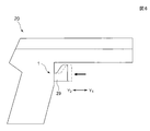
- a gun-type controller 20 shown in FIG. 6 is used as a game controller when a shooting game is performed.
- the operation device 1 is mounted on the gun-type controller 20, and an operation portion 29 shaped like a trigger is fixed to the front portion of the moving member 5 instead of the operation portion 9 shown in FIGS. 1 to 3.
- the motor 10 starts and the operation unit 29 moves forward to the initial position indicated by the chain line in FIG.
- the advance position at the initial position of the operation unit 29 differs depending on the game content being processed at that time.
- the operation unit 29 When the operation unit 29 is pushed in the Y2 direction with the finger or hand of the game operator, an image fired from the gun image is displayed on the simulation screen of the shooting game displayed on the display unit 19b, and the sound of the firing is emitted from the speaker. Be emitted.
- the motor 10 is controlled according to the content of the game, and a reaction force, an impact force, or a vibration force is applied to the hand or finger pushing the operation unit 29.
- the initial menu screen is displayed on the setting screen, and the type of gun used in the game can be selected.
- a game to be executed can be selected from a pistol or a machine gun.
- the storage unit 19a stores an operation pattern related to an operation reaction force corresponding to each gun, and any one is selected and read out, and the motor 10 is controlled based on the selected operation pattern. Therefore, depending on the type of gun, the load when the trigger is pressed, play (movement amount), magnitude of reaction, frequency of reaction, and the like can be made different.
- the gun type used in the game and the operation pattern for driving the motor are associated and mapped. Therefore, when a gun type used in the game is selected, an operation pattern corresponding to the gun type is called from the storage unit 19a.
- the gun selected in the game is a pistol (short gun)
- the operation unit 29 is pushed from the initial position
- a little resistance is applied from the motor 10
- the operation unit 29 is pushed to a predetermined distance.
- the motor 10 is operated for one cycle of normal rotation and reverse rotation, the moving member 5 is vibrated back and forth only once, and a force corresponding to the reaction at the time of firing is given to the operation unit 29.
- the vibration at this time may be performed at a predetermined frequency for a plurality of periods.
- the frequency and period of vibration applied to the moving member 5 when the operation unit 9 is pushed, and the torque of the motor 10 at the time of vibration are changed. It is possible to give an operation reaction according to the size.
- Game software includes bullet information that informs the number of bullets loaded in the gun. This bullet information is also displayed on the display unit 19b.
- the position of the moving member 5 can be controlled such that the protruding position of the operation unit 29 changes as the number of usable bullets decreases. Also, when the number of usable bullets becomes zero (out of bullet), the power supplied to the motor 10 is instantaneously zeroed, the reaction force acting on the moving member 5 in the Y1 direction is eliminated, The trigger load may be reduced rapidly. In this case, when a new bullet is replenished, the motor 10 is started, the moving member 5 is moved in the Y1 direction, and the position of the operation unit 9 is returned to the initial position indicated by the chain line in FIG. it can.
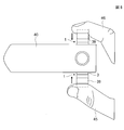
- the controller used in the shooting game is not limited to the gun-type controller 20 shown in FIG. 6, but may be a stick-type controller 30 shown in FIG.
- the stick-type controller 30 By holding the stick-type controller 30 by hand, placing a finger on the operation unit 29 and pressing it in the Y2 direction, the shooting game can be operated in the same manner as described above.
- the drive of the motor 10 is controlled by feedback from the control device 19.
- a control device may be provided inside the controllers 20 and 30 shown in FIGS. 6 and 7, and the motor 10 may be driven by a control operation from the control device.
- a game other than the shooting game may be performed by the controller including the operation device 1.
- an accelerator or a brake operation can be performed by pressing the operation units 9 and 29.
- the reaction force according to the pushing position of the operation part 9 can be generated by the motor 10.
- two sets of operating devices 1 are provided in the controller 40 so that the two operating units 39 and 39 can be operated individually.
- the controller 40 can perform a simulation of operating a manipulator 42 displayed on the display unit 19b, for example, as shown in FIG.
- the object 43 can be pinched by the two arms 42 a and 42 b of the manipulator 42 displayed on the screen by individually operating the operation units 39 and 39 with the two fingers 45 and 46.
- manipulator 42 is not limited to the simulation displayed on the screen, and a manipulator that can actually move by a machine operation can be operated by the controller 40.
- the operation unit 39 can be operated with each of five fingers in one hand. In this case, it is possible to give the operator a feeling of gripping an object with five fingers.
- the application range of the operating device 1 according to the present embodiment is very wide, and can be applied to other than the manipulator.
Abstract
L'invention a pour but de fournir un dispositif de manipulation qui possède une sensation souhaitable de manipulation par pression du doigt ou de la main, et qui soit capable de provoquer un recul provenant d'un moteur pour agir directement sur le doigt ou la main. Pour atteindre ce but, un élément mobile 5, qui se déplace en va-et-vient, comprend une partie épaisse 5a et une partie mince 5b. Une partie d'appui, qui est formée sur la partie épaisse 5a, est portée de façon coulissante sur un arbre de guidage 6, et une partie coulisseau 5d, qui est formée sur la partie mince 5b, est guidée en coulissement sur une partie guide de coulisseau 7. La puissance d'entraînement d'un moteur 10 est transmise, par l'intermédiaire d'une roue de décélération 12 et d'un mécanisme de décélération à l'intérieur d'une boîte d'engrenages 13, à un pignon d'attaque 14, et un mouvement de recul est communiqué du pignon d'attaque 14 à une partie crémaillère 15. La partie crémaillère 15 est située sur un noyau d'arbre Os, ainsi, une force est efficacement communiquée à l'élément mobile 5 par la puissance d'entraînement provenant du moteur 10.
Priority Applications (4)
| Application Number | Priority Date | Filing Date | Title |
|---|---|---|---|
| CN201580059994.7A CN107003688B (zh) | 2014-11-04 | 2015-10-06 | 操作装置 |
| JP2016557504A JP6220083B2 (ja) | 2014-11-04 | 2015-10-06 | 操作装置 |
| EP15856734.7A EP3217247B1 (fr) | 2014-11-04 | 2015-10-06 | Dispositif de manipulation |
| US15/480,166 US10684639B2 (en) | 2014-11-04 | 2017-04-05 | Operation device |
Applications Claiming Priority (2)
| Application Number | Priority Date | Filing Date | Title |
|---|---|---|---|
| JP2014224741 | 2014-11-04 | ||
| JP2014-224741 | 2014-11-04 |
Related Child Applications (1)
| Application Number | Title | Priority Date | Filing Date |
|---|---|---|---|
| US15/480,166 Continuation US10684639B2 (en) | 2014-11-04 | 2017-04-05 | Operation device |
Publications (1)
| Publication Number | Publication Date |
|---|---|
| WO2016072196A1 true WO2016072196A1 (fr) | 2016-05-12 |
Family
ID=55908924
Family Applications (1)
| Application Number | Title | Priority Date | Filing Date |
|---|---|---|---|
| PCT/JP2015/078287 WO2016072196A1 (fr) | 2014-11-04 | 2015-10-06 | Dispositif de manipulation |
Country Status (5)
| Country | Link |
|---|---|
| US (1) | US10684639B2 (fr) |
| EP (1) | EP3217247B1 (fr) |
| JP (1) | JP6220083B2 (fr) |
| CN (1) | CN107003688B (fr) |
| WO (1) | WO2016072196A1 (fr) |
Families Citing this family (2)
| Publication number | Priority date | Publication date | Assignee | Title |
|---|---|---|---|---|
| EP3564200A1 (fr) | 2018-05-04 | 2019-11-06 | Merck Patent GmbH | Couleurs céramiques |
| CN112206506A (zh) * | 2019-07-11 | 2021-01-12 | 深圳市百思度科技有限公司 | 一种扳机键及游戏手柄 |
Citations (3)
| Publication number | Priority date | Publication date | Assignee | Title |
|---|---|---|---|---|
| JPH02278078A (ja) * | 1989-04-18 | 1990-11-14 | Kubota Corp | 変速装置の変速操作構造 |
| JP2000202155A (ja) * | 1999-01-20 | 2000-07-25 | Namco Ltd | ゲ―ム装置用の振動発生装置及びゲ―ム装置用の銃模型 |
| JP2001190841A (ja) * | 2000-01-07 | 2001-07-17 | Namco Ltd | ゲーム機の振動発生装置 |
Family Cites Families (54)
| Publication number | Priority date | Publication date | Assignee | Title |
|---|---|---|---|---|
| US4131033A (en) * | 1977-02-18 | 1978-12-26 | Rockwell International Corporation | Push-pull and rotating knob |
| US4608526A (en) * | 1985-04-19 | 1986-08-26 | The United States Of America As Represented By The United States Department Of Energy | Electromechanical actuator for the tongs of a servomanipulator |
| US4724715A (en) * | 1986-04-30 | 1988-02-16 | Culver Craig F | Control mechanism for computer keyboard and the like |
| US5317336A (en) * | 1992-06-23 | 1994-05-31 | Hall Kenneth J | Mouse yoke assembly for interfacing with a computer |
| US5629594A (en) * | 1992-12-02 | 1997-05-13 | Cybernet Systems Corporation | Force feedback system |
| US7345672B2 (en) * | 1992-12-02 | 2008-03-18 | Immersion Corporation | Force feedback system and actuator power management |
| JP2856036B2 (ja) | 1993-07-12 | 1999-02-10 | 株式会社セガ・エンタープライゼス | スライド式振動機構を備えたゲーム機用ガンユニット及びゲーム装置 |
| US5731804A (en) * | 1995-01-18 | 1998-03-24 | Immersion Human Interface Corp. | Method and apparatus for providing high bandwidth, low noise mechanical I/O for computer systems |
| US5652603A (en) * | 1994-06-16 | 1997-07-29 | Abrams; Daniel Lawrence | 3-D computer input device |
| US5569085A (en) * | 1994-07-29 | 1996-10-29 | Namco Limited | Gun game machine having a sliding gun barrel cover for simulating the impact of a fired gun |
| US5666138A (en) * | 1994-11-22 | 1997-09-09 | Culver; Craig F. | Interface control |
| US5825308A (en) * | 1996-11-26 | 1998-10-20 | Immersion Human Interface Corporation | Force feedback interface having isotonic and isometric functionality |
| US5823876A (en) * | 1996-05-03 | 1998-10-20 | Unbehand; Erick Michael | Steering wheel simulation assembly |
| US5990869A (en) * | 1996-08-20 | 1999-11-23 | Alliance Technologies Corp. | Force feedback mouse |
| US6154201A (en) * | 1996-11-26 | 2000-11-28 | Immersion Corporation | Control knob with multiple degrees of freedom and force feedback |
| US7489309B2 (en) * | 1996-11-26 | 2009-02-10 | Immersion Corporation | Control knob with multiple degrees of freedom and force feedback |
| US7038667B1 (en) * | 1998-10-26 | 2006-05-02 | Immersion Corporation | Mechanisms for control knobs and other interface devices |
| US7499021B2 (en) * | 2000-10-27 | 2009-03-03 | Makex Limited | Haptic input devices |
| US7235013B2 (en) | 2000-12-07 | 2007-06-26 | Konami Corporation | Game machine using self-propelled members |
| JP3900085B2 (ja) * | 2003-01-14 | 2007-04-04 | ミツミ電機株式会社 | ゲーム用コントローラ |
| JP4446712B2 (ja) * | 2003-10-23 | 2010-04-07 | アルプス電気株式会社 | 力覚付与型入力装置 |
| US20170262080A1 (en) * | 2004-02-04 | 2017-09-14 | Anascape, Ltd. | 6DOF Proportional Controls Housed with Electronic Displays |
| JP3971397B2 (ja) * | 2004-03-16 | 2007-09-05 | 株式会社コナミデジタルエンタテインメント | 模擬銃 |
| US8525778B2 (en) * | 2007-03-21 | 2013-09-03 | Northwestern University | Haptic device with controlled traction forces |
| US8545323B2 (en) * | 2006-06-30 | 2013-10-01 | Logitech Europe S.A. | Video game controller with compact and efficient force feedback mechanism |
| US9128525B2 (en) * | 2008-01-04 | 2015-09-08 | Tactus Technology, Inc. | Dynamic tactile interface |
| US9588683B2 (en) * | 2008-01-04 | 2017-03-07 | Tactus Technology, Inc. | Dynamic tactile interface |
| WO2010080766A2 (fr) * | 2009-01-06 | 2010-07-15 | Immersion Corporation | Contrôleur de pistolet à activation haptique pour jeu programmable |
| US8610548B1 (en) * | 2009-02-03 | 2013-12-17 | University Of Utah Research Foundation | Compact shear tactile feedback device and related methods |
| EP2226704B1 (fr) * | 2009-03-02 | 2012-05-16 | Anoto AB | Stylo numérique |
| TWI434721B (zh) * | 2010-03-23 | 2014-04-21 | Yung Sen Ltd Company | 迴轉式射擊遊戲系統 |
| US10318002B2 (en) * | 2010-09-15 | 2019-06-11 | Inventus Engineering Gmbh | Magnetorheological transmission device |
| JP5577211B2 (ja) * | 2010-10-05 | 2014-08-20 | アルプス電気株式会社 | 力覚付与型多方向入力装置 |
| JP2012139763A (ja) * | 2010-12-28 | 2012-07-26 | Hitachi Koki Co Ltd | 動力工具 |
| US20140214206A1 (en) * | 2011-10-26 | 2014-07-31 | Cambridge Surgical Instruments, Inc. | Device for providing tactile feedback for robotic apparatus using actuation |
| CN202607214U (zh) * | 2012-04-28 | 2012-12-19 | 天津博信汽车零部件有限公司 | 电枪反力装置 |
| WO2014041923A1 (fr) * | 2012-09-13 | 2014-03-20 | 株式会社ソニー・コンピュータエンタテインメント | Dispositif haptique |
| NL1040096C2 (en) * | 2012-11-14 | 2014-09-16 | Holland Haptics B V | Haptic communication system, method and device. |
| US11826636B2 (en) * | 2013-07-12 | 2023-11-28 | Chris Argiro | Depth sensing module and mobile device including the same |
| EP2760003A1 (fr) * | 2013-01-24 | 2014-07-30 | Surgical Science Sweden AB | Dispositif d'interface utilisateur haptique pour système de simulation chirurgicale |
| US9557830B2 (en) * | 2013-03-15 | 2017-01-31 | Immersion Corporation | Programmable haptic peripheral |
| JP6469963B2 (ja) * | 2013-04-22 | 2019-02-13 | イマージョン コーポレーションImmersion Corporation | 触覚対応トリガーを有するゲーミング装置 |
| US20150205352A1 (en) * | 2013-12-29 | 2015-07-23 | Immersion Corporation | Distributed control architecture for haptic devices |
| WO2016051986A1 (fr) * | 2014-09-30 | 2016-04-07 | アルプス電気株式会社 | Dispositif d'actionnement |
| US9746925B2 (en) * | 2015-05-20 | 2017-08-29 | Raw Thrills, Inc. | Haptic feedback device using a dual coil linear solenoid |
| US9841818B2 (en) * | 2015-12-21 | 2017-12-12 | Immersion Corporation | Haptic peripheral having a plurality of deformable membranes and a motor to move radial pins |
| JP6749429B2 (ja) * | 2017-02-06 | 2020-09-02 | アルプスアルパイン株式会社 | 触覚呈示装置 |
| US10384123B2 (en) * | 2017-06-01 | 2019-08-20 | Microsoft Technology Licensing, Llc | Motor-driven adjustable-tension trigger |
| US10773159B2 (en) * | 2017-06-01 | 2020-09-15 | Microsoft Technology Licensing, Llc | Input device with linear geared feedback trigger |
| US10226697B2 (en) * | 2017-06-01 | 2019-03-12 | Microsoft Technology Licensing, Llc | Input device with sector geared feedback trigger |
| US10241577B2 (en) * | 2017-08-01 | 2019-03-26 | Immersion Corporation | Single actuator haptic effects |
| US10775891B2 (en) * | 2018-04-02 | 2020-09-15 | Microsoft Technology Licensing, Llc | Resistance-based haptic device |
| US20200023270A1 (en) * | 2018-07-18 | 2020-01-23 | Immersion Corporation | Trigger Button For Haptic Controller |
| CN109091857B (zh) * | 2018-09-13 | 2020-09-11 | 黄嘉欣 | 一种易收纳组合式无线枪形仿真游戏手柄 |
-
2015
- 2015-10-06 CN CN201580059994.7A patent/CN107003688B/zh active Active
- 2015-10-06 JP JP2016557504A patent/JP6220083B2/ja active Active
- 2015-10-06 EP EP15856734.7A patent/EP3217247B1/fr active Active
- 2015-10-06 WO PCT/JP2015/078287 patent/WO2016072196A1/fr active Application Filing
-
2017
- 2017-04-05 US US15/480,166 patent/US10684639B2/en active Active
Patent Citations (3)
| Publication number | Priority date | Publication date | Assignee | Title |
|---|---|---|---|---|
| JPH02278078A (ja) * | 1989-04-18 | 1990-11-14 | Kubota Corp | 変速装置の変速操作構造 |
| JP2000202155A (ja) * | 1999-01-20 | 2000-07-25 | Namco Ltd | ゲ―ム装置用の振動発生装置及びゲ―ム装置用の銃模型 |
| JP2001190841A (ja) * | 2000-01-07 | 2001-07-17 | Namco Ltd | ゲーム機の振動発生装置 |
Also Published As
| Publication number | Publication date |
|---|---|
| US10684639B2 (en) | 2020-06-16 |
| EP3217247A1 (fr) | 2017-09-13 |
| CN107003688B (zh) | 2018-10-09 |
| US20170212548A1 (en) | 2017-07-27 |
| EP3217247B1 (fr) | 2019-06-12 |
| CN107003688A (zh) | 2017-08-01 |
| EP3217247A4 (fr) | 2018-07-04 |
| JPWO2016072196A1 (ja) | 2017-08-03 |
| JP6220083B2 (ja) | 2017-10-25 |
Similar Documents
| Publication | Publication Date | Title |
|---|---|---|
| JP6531109B2 (ja) | 操作装置 | |
| JP6434769B2 (ja) | ゲーム用コントローラ | |
| US9050529B2 (en) | Force feedback triggers | |
| EP1226852B1 (fr) | Mécanisme à force de rétroaction pour dispositif de commande de jeux | |
| US8981682B2 (en) | Asymmetric and general vibration waveforms from multiple synchronized vibration actuators | |
| JP5025147B2 (ja) | 遊技機の可動装飾装置 | |
| JP6220083B2 (ja) | 操作装置 | |
| US20220236805A1 (en) | Handwheels and Associated Control Consoles | |
| JP2015111542A (ja) | 入力装置 | |
| JP2005332156A (ja) | 力覚付与型入力装置 | |
| JP7157980B2 (ja) | 運動訓練装置 | |
| JP5238626B2 (ja) | 感覚提示装置 | |
| KR100586533B1 (ko) | 보이스 코일 모터를 이용한 햅틱 시스템 | |
| WO2017006671A1 (fr) | Dispositif de reproduction de sensation tactile | |
| WO2017006670A1 (fr) | Dispositif de reproduction de sensations tactiles | |
| JP6465357B2 (ja) | 操作装置 | |
| JP7209282B2 (ja) | 運動訓練装置 | |
| WO2021119672A1 (fr) | Volants et consoles de commande associées | |
| JP7004549B2 (ja) | 運動訓練装置 | |
| WO2017159032A1 (fr) | Dispositif de reproduction de tactilité et procédé de commande associé | |
| US20240160291A1 (en) | Handwheels and associated control consoles | |
| JP2022156174A (ja) | 運動訓練装置及びプログラム | |
| JP2020006246A (ja) | 演出装置及び遊技機 | |
| JP2014021597A (ja) | 触覚呈示装置 |
Legal Events
| Date | Code | Title | Description |
|---|---|---|---|
| 121 | Ep: the epo has been informed by wipo that ep was designated in this application |
Ref document number: 15856734 Country of ref document: EP Kind code of ref document: A1 |
|
| ENP | Entry into the national phase |
Ref document number: 2016557504 Country of ref document: JP Kind code of ref document: A |
|
| REEP | Request for entry into the european phase |
Ref document number: 2015856734 Country of ref document: EP |
|
| NENP | Non-entry into the national phase |
Ref country code: DE |