WO2016063416A1 - 送風装置 - Google Patents
送風装置 Download PDFInfo
- Publication number
- WO2016063416A1 WO2016063416A1 PCT/JP2014/078364 JP2014078364W WO2016063416A1 WO 2016063416 A1 WO2016063416 A1 WO 2016063416A1 JP 2014078364 W JP2014078364 W JP 2014078364W WO 2016063416 A1 WO2016063416 A1 WO 2016063416A1
- Authority
- WO
- WIPO (PCT)
- Prior art keywords
- pair
- fitting
- annular member
- portions
- sheet
- Prior art date
Links
Images


Classifications
-
- F—MECHANICAL ENGINEERING; LIGHTING; HEATING; WEAPONS; BLASTING
- F04—POSITIVE - DISPLACEMENT MACHINES FOR LIQUIDS; PUMPS FOR LIQUIDS OR ELASTIC FLUIDS
- F04D—NON-POSITIVE-DISPLACEMENT PUMPS
- F04D29/00—Details, component parts, or accessories
- F04D29/60—Mounting; Assembling; Disassembling
- F04D29/64—Mounting; Assembling; Disassembling of axial pumps
- F04D29/644—Mounting; Assembling; Disassembling of axial pumps especially adapted for elastic fluid pumps
-
- A—HUMAN NECESSITIES
- A47—FURNITURE; DOMESTIC ARTICLES OR APPLIANCES; COFFEE MILLS; SPICE MILLS; SUCTION CLEANERS IN GENERAL
- A47C—CHAIRS; SOFAS; BEDS
- A47C7/00—Parts, details, or accessories of chairs or stools
- A47C7/02—Seat parts
- A47C7/021—Detachable or loose seat cushions
-
- A—HUMAN NECESSITIES
- A47—FURNITURE; DOMESTIC ARTICLES OR APPLIANCES; COFFEE MILLS; SPICE MILLS; SUCTION CLEANERS IN GENERAL
- A47C—CHAIRS; SOFAS; BEDS
- A47C7/00—Parts, details, or accessories of chairs or stools
- A47C7/62—Accessories for chairs
- A47C7/72—Adaptations for incorporating lamps, radio sets, bars, telephones, ventilation, heating or cooling arrangements or the like
- A47C7/74—Adaptations for incorporating lamps, radio sets, bars, telephones, ventilation, heating or cooling arrangements or the like for ventilation, heating or cooling
- A47C7/742—Adaptations for incorporating lamps, radio sets, bars, telephones, ventilation, heating or cooling arrangements or the like for ventilation, heating or cooling for ventilating or cooling
- A47C7/744—Adaptations for incorporating lamps, radio sets, bars, telephones, ventilation, heating or cooling arrangements or the like for ventilation, heating or cooling for ventilating or cooling with active means, e.g. by using air blowers or liquid pumps
-
- F—MECHANICAL ENGINEERING; LIGHTING; HEATING; WEAPONS; BLASTING
- F04—POSITIVE - DISPLACEMENT MACHINES FOR LIQUIDS; PUMPS FOR LIQUIDS OR ELASTIC FLUIDS
- F04D—NON-POSITIVE-DISPLACEMENT PUMPS
- F04D25/00—Pumping installations or systems
- F04D25/02—Units comprising pumps and their driving means
- F04D25/08—Units comprising pumps and their driving means the working fluid being air, e.g. for ventilation
- F04D25/12—Units comprising pumps and their driving means the working fluid being air, e.g. for ventilation the unit being adapted for mounting in apertures
-
- F—MECHANICAL ENGINEERING; LIGHTING; HEATING; WEAPONS; BLASTING
- F04—POSITIVE - DISPLACEMENT MACHINES FOR LIQUIDS; PUMPS FOR LIQUIDS OR ELASTIC FLUIDS
- F04D—NON-POSITIVE-DISPLACEMENT PUMPS
- F04D29/00—Details, component parts, or accessories
- F04D29/02—Selection of particular materials
- F04D29/023—Selection of particular materials especially adapted for elastic fluid pumps
-
- F—MECHANICAL ENGINEERING; LIGHTING; HEATING; WEAPONS; BLASTING
- F04—POSITIVE - DISPLACEMENT MACHINES FOR LIQUIDS; PUMPS FOR LIQUIDS OR ELASTIC FLUIDS
- F04D—NON-POSITIVE-DISPLACEMENT PUMPS
- F04D29/00—Details, component parts, or accessories
- F04D29/40—Casings; Connections of working fluid
- F04D29/42—Casings; Connections of working fluid for radial or helico-centrifugal pumps
- F04D29/4206—Casings; Connections of working fluid for radial or helico-centrifugal pumps especially adapted for elastic fluid pumps
-
- F—MECHANICAL ENGINEERING; LIGHTING; HEATING; WEAPONS; BLASTING
- F04—POSITIVE - DISPLACEMENT MACHINES FOR LIQUIDS; PUMPS FOR LIQUIDS OR ELASTIC FLUIDS
- F04D—NON-POSITIVE-DISPLACEMENT PUMPS
- F04D29/00—Details, component parts, or accessories
- F04D29/40—Casings; Connections of working fluid
- F04D29/52—Casings; Connections of working fluid for axial pumps
- F04D29/522—Casings; Connections of working fluid for axial pumps especially adapted for elastic fluid pumps
-
- F—MECHANICAL ENGINEERING; LIGHTING; HEATING; WEAPONS; BLASTING
- F04—POSITIVE - DISPLACEMENT MACHINES FOR LIQUIDS; PUMPS FOR LIQUIDS OR ELASTIC FLUIDS
- F04D—NON-POSITIVE-DISPLACEMENT PUMPS
- F04D29/00—Details, component parts, or accessories
- F04D29/60—Mounting; Assembling; Disassembling
- F04D29/601—Mounting; Assembling; Disassembling specially adapted for elastic fluid pumps
- F04D29/602—Mounting in cavities
-
- F—MECHANICAL ENGINEERING; LIGHTING; HEATING; WEAPONS; BLASTING
- F04—POSITIVE - DISPLACEMENT MACHINES FOR LIQUIDS; PUMPS FOR LIQUIDS OR ELASTIC FLUIDS
- F04D—NON-POSITIVE-DISPLACEMENT PUMPS
- F04D29/00—Details, component parts, or accessories
- F04D29/60—Mounting; Assembling; Disassembling
- F04D29/62—Mounting; Assembling; Disassembling of radial or helico-centrifugal pumps
- F04D29/624—Mounting; Assembling; Disassembling of radial or helico-centrifugal pumps especially adapted for elastic fluid pumps
- F04D29/626—Mounting or removal of fans
-
- F—MECHANICAL ENGINEERING; LIGHTING; HEATING; WEAPONS; BLASTING
- F04—POSITIVE - DISPLACEMENT MACHINES FOR LIQUIDS; PUMPS FOR LIQUIDS OR ELASTIC FLUIDS
- F04D—NON-POSITIVE-DISPLACEMENT PUMPS
- F04D29/00—Details, component parts, or accessories
- F04D29/60—Mounting; Assembling; Disassembling
- F04D29/64—Mounting; Assembling; Disassembling of axial pumps
- F04D29/644—Mounting; Assembling; Disassembling of axial pumps especially adapted for elastic fluid pumps
- F04D29/646—Mounting or removal of fans
-
- A—HUMAN NECESSITIES
- A41—WEARING APPAREL
- A41D—OUTERWEAR; PROTECTIVE GARMENTS; ACCESSORIES
- A41D13/00—Professional, industrial or sporting protective garments, e.g. surgeons' gowns or garments protecting against blows or punches
- A41D13/002—Professional, industrial or sporting protective garments, e.g. surgeons' gowns or garments protecting against blows or punches with controlled internal environment
- A41D13/0025—Professional, industrial or sporting protective garments, e.g. surgeons' gowns or garments protecting against blows or punches with controlled internal environment by means of forced air circulation
-
- F—MECHANICAL ENGINEERING; LIGHTING; HEATING; WEAPONS; BLASTING
- F04—POSITIVE - DISPLACEMENT MACHINES FOR LIQUIDS; PUMPS FOR LIQUIDS OR ELASTIC FLUIDS
- F04D—NON-POSITIVE-DISPLACEMENT PUMPS
- F04D25/00—Pumping installations or systems
- F04D25/02—Units comprising pumps and their driving means
- F04D25/08—Units comprising pumps and their driving means the working fluid being air, e.g. for ventilation
- F04D25/084—Units comprising pumps and their driving means the working fluid being air, e.g. for ventilation hand fans
-
- F—MECHANICAL ENGINEERING; LIGHTING; HEATING; WEAPONS; BLASTING
- F05—INDEXING SCHEMES RELATING TO ENGINES OR PUMPS IN VARIOUS SUBCLASSES OF CLASSES F01-F04
- F05D—INDEXING SCHEME FOR ASPECTS RELATING TO NON-POSITIVE-DISPLACEMENT MACHINES OR ENGINES, GAS-TURBINES OR JET-PROPULSION PLANTS
- F05D2250/00—Geometry
- F05D2250/10—Two-dimensional
- F05D2250/14—Two-dimensional elliptical
-
- F—MECHANICAL ENGINEERING; LIGHTING; HEATING; WEAPONS; BLASTING
- F05—INDEXING SCHEMES RELATING TO ENGINES OR PUMPS IN VARIOUS SUBCLASSES OF CLASSES F01-F04
- F05D—INDEXING SCHEME FOR ASPECTS RELATING TO NON-POSITIVE-DISPLACEMENT MACHINES OR ENGINES, GAS-TURBINES OR JET-PROPULSION PLANTS
- F05D2300/00—Materials; Properties thereof
- F05D2300/50—Intrinsic material properties or characteristics
- F05D2300/501—Elasticity
Definitions
- the present invention is used, for example, in air-flowing mats and air-conditioning clothes that evaporate sweat from a human body by circulating air, and is attached to sheet-like members that are fabrics such as air-flowing mats and air-conditioning clothes.
- the present invention relates to a blower.
- an air-flowing mat such as an air-conditioning cushion includes a spacer, a sheet-like member, and a blower.
- the spacer is for securing a space inside the air circulation type mat.
- the sheet-like member covers the spacer, and a cloth or the like is used as the sheet-like member.
- the blower is for generating an air flow in the space secured by the spacer. This blower is attached to a sheet-like member.
- the conventional blower is temporarily configured to be detachable from the sheet-like member.
- the user cannot easily attach the blower device to the sheet-like member, and cannot easily remove it from the sheet-like member.
- the conventional air blower has a problem that the detachability is not good.
- the present invention has been made based on the above circumstances, and an object thereof is to provide a blower having a simple structure that can be easily attached to and detached from a sheet-like member by a user.
- the present invention for achieving the above object is a blower device that is attached to a sheet-like member and generates a flow of air from one side of the sheet-like member to the other side, the fan body,
- An annular member for attaching the fan main body to the sheet-like member, and the fan main body has a hollow cylindrical portion and a cylindrical portion protruding from the outer surface of the cylindrical body in a direction substantially perpendicular to the outer surface.
- the inner space of the annular member in the pair of pressing portions that are two portions that are smaller than the outer space of the cylindrical portion in the pair of first portions and are approximately 90 degrees different from the pair of second portions. It is larger than the outer space of the cylindrical part in two parts that are approximately 90 degrees different from one part, the inner periphery of the annular member is larger than the outer periphery of the cylindrical part, and the annular member has flexibility, The edge of the sheet-like member around the opening formed in the sheet-like member by inserting the annular member outside the cylindrical part by utilizing the flexibility of the member, and the back surface of the flange part and one end face of the annular member The first mating while sandwiching the part By fitting the step and the second fitting means, the fan main body is attached to the sheet-like member, the pair of pressing portions in the annular member is pressed, and the annular member is bent to thereby The fan body is detached from the sheet-like member by releasing the fitting with the two fitting means.
- the present invention for achieving the above object is a blower device that is attached to a sheet-like member and generates a flow of air from one side of the sheet-like member toward the other side.
- an annular member for attaching the fan main body to the sheet-like member.
- the fan main body has a hollow cylindrical portion and a cylindrical shape protruding from the outer surface of the cylindrical body in a direction substantially perpendicular to the outer surface.
- An annular member in a pair of second parts The inner interval is the same as the outer interval of the cylindrical part in the pair of first parts or smaller than the outer interval of the cylindrical part in the pair of first parts, and is approximately 90 degrees different from the pair of second parts.
- the distance between the inner sides of the annular member in the pair of pressing parts, which are two parts, is larger than the outer space of the cylindrical part in two parts that are approximately 90 degrees different from the pair of first parts.
- the annular member is larger than the outer periphery, and the annular member has flexibility, and is chamfered at the corners on the outer side of the pair of pressing portions of the annular member that faces the flange portion.
- the sheet-like shape around the opening formed in the sheet-like member is formed by inserting the annular member outside the tubular part using the flexibility of the annular member, and the back surface of the flange part and one end face of the annular member.
- the first fitting means while sandwiching the edge of the member
- the fan body is attached to the sheet-like member, the pair of pressing portions in the annular member is pressed, and the annular member is bent, so that the first fitting means and the second fitting are
- the fan main body is detached from the sheet-like member by releasing the fitting with the coupling means.
- the fan main body is arranged so that the back surface of the flange portion of the fan main body is in contact with the edge of the sheet-like member around the opening formed in the sheet-like member.
- the position of the first fitting means of the main body and the position of the second fitting means of the annular member are matched, and the annular member is attached to the cylindrical portion of the fan main body from below the fan main body by utilizing the flexibility of the annular member.
- the edge of the sheet-like member around the opening of the sheet-like member is sandwiched between the back surface of the flange portion of the fan body and one end surface of the annular member.
- the air blower can be firmly attached to the sheet-like member.
- the pair of pressing portions of the annular member is pinched by the thumb and the index finger, and the inner surface of the pair of pressing portions is utilized by the flexibility of the annular member. What is necessary is just to press so that the outer surface of a cylindrical part may contact
- the air blower of the present invention has a simple structure, and the user can easily attach and remove the air blower to the sheet-like member.
- the blower of the present invention by providing one or a plurality of protrusions on the outer side of the annular member in the second part and the vicinity thereof for each of the pair of second parts, or a pair of annular members By chamfering the outer corner on the side opposite to the flange portion on the pressing part side, the shape of the annular member in contact with the sheet-like member becomes substantially circular, so for some reason the sheet Even when a force directed from the inside to the outside of the shaped member is applied to the blower of the present invention, an equal force is applied to the annular member, so that the annular member can be prevented from falling off.
- the air blower of the present invention has a simple structure, and the user can easily attach and remove the air blower to the sheet-like member.
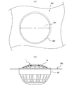
- FIG. 1A is a schematic perspective view of a chair airflow mat using the air blower according to the first embodiment of the present invention
- FIG. 1B is a diagram of the airflow mat used. It is a schematic sectional drawing.
- Fig.2 (a) is a schematic front view of the air blower of 1st embodiment
- FIG.2 (b) is a schematic side view of the air blower.
- FIG. 3A is a diagram for explaining an opening formed in the sheet-like member
- FIG. 3B is a schematic side view for explaining a state in which a blower is attached to the sheet-like member.
- FIG. 4A is a schematic side view of a main body case in the blower of the first embodiment
- FIG. 4B is a schematic side view of a flanged cylindrical portion which is a main part of the present invention, in the main body case.
- FIG. 4 (c) is a schematic side view of the flanged cylindrical portion when the flanged cylindrical portion shown in FIG. 4 (b) is rotated 90 degrees around its central axis
- FIG. 4 (d) is the flange.
- FIG. 6 is a schematic cross-sectional view of the attached cylindrical portion in the direction of arrow AA.
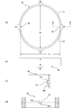
- 5 (a) is a schematic front view of the mounting ring in the blower of the first embodiment
- FIG. 5 (b) is a schematic side view of the mounting ring
- FIG. 5 (c) is a BB view of the mounting ring.
- FIG. 5 (a) is a schematic front view of the mounting ring in the blower of the first embodiment
- FIG. 5 (b) is a schematic side view of the mounting ring
- FIG. 5 (c) is a BB view of the mounting
- FIG. 5D is a schematic cross-sectional view in the direction of arrow CC of the mounting ring.
- FIG. 6A is a schematic perspective view of a flanged cylindrical portion in the blower of the first embodiment
- FIG. 6B is a schematic cross-sectional view of the flanged cylindrical portion in the direction of arrow DD.
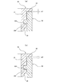
- FIG. 7A is a schematic partial sectional view for explaining a fitting state between the flanged cylindrical portion and the mounting ring
- FIG. 7B is a flanged cylindrical portion when the mounting ring is turned upside down. It is a general
- FIG. 8A is a schematic side view for explaining a state when the fan body is inserted into the opening of the sheet-like member
- FIG. 8B is a view when the blower is attached to the opening of the sheet-like member. It is a schematic side view for demonstrating a mode.
- FIG. 9A is a schematic rear view of the fan main body to which the mounting ring is attached
- FIG. 9B is a diagram for explaining a state when the pair of pressing portions of the mounting ring are pressed toward the center in the fan main body.
- FIG. FIG. 10 is a diagram showing the force that the mounting ring 50 receives from the bent sheet-like member 200.
- FIG. 11A is a schematic plan view of a chamfered mounting ring
- FIG. 11B is a diagram for explaining a state in which the blower is attached to the sheet-like member using the chamfered mounting ring.
- FIG. FIG. 12A is a schematic rear view of the fan body in the blower of the second embodiment
- FIG. 12B is a schematic front view of the mounting ring in the blower of the second embodiment.
- FIG. 13A is a schematic perspective view of a flanged cylindrical portion in the blower of the third embodiment
- FIG. 13B is a schematic sectional view of the flanged cylindrical portion in the direction of arrow EE
- FIG. c) is a schematic front view of the mounting ring in the blower of the third embodiment
- FIG. 13 (d) is a schematic cross-sectional view in the direction of arrow FF of the mounting ring.
- 14A is a schematic side view of the flanged cylindrical portion in the blower of the fourth embodiment
- FIG. 14B is a schematic sectional view of the flanged cylindrical portion in the direction of arrow GG
- 14C is a schematic perspective view of the mounting ring in the blower of the fourth embodiment
- FIG. 14D is a schematic cross-sectional view in the direction of arrow HH of the mounting ring.
- 15A is a schematic plan view of the mounting ring in the blower of the fifth embodiment
- FIG. 15B is a schematic side view of the mounting ring
- FIG. 15C is a schematic of the blower of the fifth embodiment. It is a back view.
- FIG. 1A is a schematic perspective view of a chair airflow mat using the air blower according to the first embodiment of the present invention
- FIG. 1B is a diagram of the airflow mat used. It is a schematic sectional drawing.
- the air circulation mat 100 for a chair is used by being laid on a seat portion of a chair, and as shown in FIGS. 1 (a) and 1 (b), a bag-like sheet-like member 200, a spacer 102, The air discharge part 103, the air blower 1 of this invention, and power supply parts (not shown), such as a battery which supplies electric power to this air blower 1, are provided.
- the bag-like sheet-like member 200 covers the spacer 102.
- cloth is used as the sheet-like member 200.
- the spacer 102 is for securing a space in the sheet-like member 200.
- the space in the sheet-like member 200 becomes an air flow passage through which air flows.
- An air discharge portion 103 is provided at a predetermined end of the air circulation mat 100, and the air that has circulated through the air flow passage is discharged from the air discharge portion 103 to the outside.
- the blower 1 is attached to a predetermined portion of the sheet-like member 200 that is located away from the air discharge unit 103.
- the air blower 1 is arrange
- the blower 1 is for generating a flow of air from one side of the sheet-like member 200 toward the other side.
- the air blower 1 of the first embodiment is used as a blower.
- a propeller type having a low pressure can be used.
- emitted from the air discharge part 103 is considered.
- FIG. 2A is a schematic front view of the blower device 1 of the first embodiment
- FIG. 2B is a schematic side view of the blower device 1.
- 3A is a diagram for explaining an opening formed in the sheet-like member 200
- FIG. 3B is a schematic side view for explaining a state in which the blower 1 is attached to the sheet-like member 200. is there.
- FIG. 4A is a schematic side view of a main body case in the blower 1 of the first embodiment
- FIG. 4B is a schematic side view of a flanged cylindrical portion which is a main part of the present invention in the main body case.
- FIG. 4 (c) is a schematic side view of the flanged tubular portion when the flanged tubular portion shown in FIG. 4 (b) is rotated 90 degrees around its central axis
- FIG. It is a schematic sectional drawing of the AA arrow direction of a cylindrical part with a flange.
- 5A is a schematic front view of the mounting ring in the blower 1 of the first embodiment
- FIG. 5B is a schematic side view of the mounting ring
- FIG. 5C is a BB arrow of the mounting ring
- FIG. 5D is a schematic cross-sectional view in the direction of arrow CC of the mounting ring.
- FIG. 6A is a schematic perspective view of the flanged cylindrical portion in the blower 1 of the first embodiment
- FIG. 6B is a schematic cross-sectional view of the flanged cylindrical portion in the direction of arrow DD.
- the blower device 1 of the first embodiment includes a fan body 10 and an attachment ring (annular member) 50 as shown in FIG.
- the fan main body 10 realizes the air blowing function which is the original function of the air blower 1, while the attachment ring 50 plays a role as a dedicated tool for attaching the fan main body 10 to the sheet-like member 200.
- the fan main body 10 includes a main body case 14, a motor (not shown) built in the main body case, a propeller (blade) 12 mounted on the rotating shaft of the motor, and a connector (see FIG. (Not shown).
- the main body case 14 shown in FIG. 4A is composed of two upper and lower parts, and is formed by combining these parts and combining them.
- this invention is related to the technique which attaches the air blower 1 to the sheet-like member 200, detailed description about a motor and the propeller 12 is abbreviate
- the main body case 14 is, as shown in FIG. 4 (a), from the top, the first flow portion 15, the flanged tubular portion 20, the second flow portion 16, Let us divide into three parts.
- the entire main body case 14 is not illustrated, and the first circulation part 15 and the second circulation part 16 are omitted, and only the flanged cylindrical part 20 is illustrated.
- the first distribution part 15 is centered on a circular central base 151, a plurality of rod-like parts 152 extending radially from the central base 151, and the central base 151. It is comprised from the ring-shaped part 153 to do. Since it is constituted in this way, the 1st distribution part 15 has sufficient air permeability, and can take in outside air inside when propeller 12 rotates. In addition, the first distribution unit 15 also serves as a finger guard that protects the fingers from the rotating propeller 12 so that the fingers do not enter from the outside. A flanged tubular portion 20 is continuous under the first flow portion 15.
- the flanged tubular portion 20 includes a flange portion 22 formed continuously to the rod-like portion 152 of the first flow portion 15 and a hollow tubular portion 21.
- the cross section when the cylindrical portion 21 is cut along a plane perpendicular to the central axis thereof is circular.
- a recess (first fitting means) 25 is formed at a predetermined portion of the cylindrical portion 21.
- the second flow portion 16 is continuous.
- the second flow part 16 includes a plurality of rod-like parts 162 and a ring-like part 163, a motor fixing part 164 for fixing the motor, and a motor fixing part 164. And a motor lid 165 attached to the lower side.
- the portion composed of the plurality of rod-shaped portions 162 and the ring-shaped portion 163 has sufficient air permeability, and the portions can protect the fingers from the rotating propeller 12 so that the fingers do not enter from the outside. it can.
- main body case 14 Since the main body case 14 is configured in this manner, when the motor fixed to the motor fixing portion 164 rotates and the propeller 12 rotates by the motor, outside air is taken in from the first circulation portion 15 and from the second circulation portion 16. Can be discharged.
- the present invention relates to a technique for attaching the blower device 1 to the opening portion opened in the sheet-like member 200, and this technique relates to a flanged cylinder that constitutes a part of the main body case 14. And a mounting ring 50. For this reason, the cylindrical part 20 with a flange is demonstrated a little in detail.
- the outer diameter (outer interval) t of the tubular portion 21 in the tubular portion 20 with flange is 90 mm.
- the inner diameter c of the opening 201 formed in the sheet-like member 200 is 90 to 91 mm, and is the same as or slightly larger than the outer diameter t of the cylindrical portion 21.
- the flange portion 22 is formed in an annular shape, and is substantially perpendicular to the outer surface of the tubular portion 21 from the upper end of the tubular portion 21. Protrudes in the direction.
- the outer diameter f of the flange portion 22 is sufficiently larger than the inner diameter c of the opening 201 formed in the sheet-like member 200, for example, 97 mm. Moreover, the outer diameter of the 2nd distribution
- circulation part 16 is 90 mm in the part connected to the cylindrical part 21, and is so small that it goes below.
- the fan main body 10 Since the relationship between each dimension of the fan main body 10 and the dimension of the opening 201 formed in the sheet-like member 200 is as described above, the fan main body 10 is viewed from above the opening 201 formed in the sheet-like member 200. Can be easily inserted, and at this time, the back surface of the flange portion 22 contacts the upper surface of the edge portion 202 of the opening 201 (see FIG. 8A).
- two predetermined portions that are symmetrical with respect to the central axis of the tubular portion 21, that is, two predetermined portions that face each other of the tubular portion 21 Recesses 25 as first fitting means are provided on the outside of the pair of first fitting parts (first parts) 23).
- the recess 25 is for fixing the mounting ring 50 to the fan body 10.
- the dent 25 has a substantially quadrangular shape when viewed from the front, and is formed substantially at the center with respect to the height direction of the cylindrical portion 21.
- the recess 25 has a fitting wall 255 on the lower surface thereof.
- the lower surface of the recess 25 itself corresponds to the fitting wall 255.
- the fitting wall 255 is formed substantially perpendicular to the outer surface of the cylindrical portion 21.
- a guide inclined portion 28 is formed at a portion outside the cylindrical portion 21 in the first fitting portion 23 and below the recess 25. As shown in FIGS. 4D and 6B, the guide inclined portion 28 is formed so that the thickness of the cylindrical portion 21 decreases as it goes downward. Further, as shown in FIG. 4C, the lateral width of the guide inclined portion 28 is approximately the same as the lateral width of the recess 25 in the upper part, but becomes wider as it goes downward.
- the mounting ring 50 As shown in FIG. 5A, the shape of the attachment ring 50 viewed from above (the cross-sectional shape when the attachment ring 50 is cut along a plane perpendicular to the central axis thereof) is an elliptical shape. Protrusions 52 serving as second fitting means are provided inside two predetermined parts (a pair of second fitting parts (second parts) 53) facing each other in the minor axis direction of the mounting ring 50. Yes.
- the mounting ring 50 including the two protrusions 52 is integrally formed by plastic molding. Thereby, the attachment ring 50 has flexibility. The height of the mounting ring 50 is uniform over the entire circumference.
- each protrusion 52 is formed slightly below the center with respect to the height direction of the mounting ring 50.
- Each of the two protrusions 52 is for fitting with the recess 25 of the fan main body 10 to fix the attachment ring 50 to the outside of the tubular portion 21. For this reason, the positional relationship between the two protrusions 52 is the same as the positional relationship between the two recesses 25.
- each protrusion 52 has a substantially quadrangular prism shape and protrudes toward the inside of the attachment ring 50.
- the size of the protrusion 52 is slightly smaller than the size of the recess 25 so that the protrusion 52 can fit into the recess 25.
- the protrusion 52 has a fitting wall 522 on its lower surface.
- the lower surface of the protrusion 52 itself corresponds to the fitting wall 522.
- the fitting wall 522 is formed substantially perpendicular to the inner surface of the mounting ring 50.
- the upper surface of the protrusion 52 serves as the fitting wall 522. That is, the protrusion 52 has a fitting wall 522 on its upper and lower surfaces. For this reason, the upper surface of the protrusion 52 is formed substantially perpendicular to the inner surface of the mounting ring 50.
- the mounting ring 50 can be used with the A side up or the B side can be used so that the blower 1 can also cope with sheet-like members 200 having different thicknesses. It can be used up.
- the letters “A” and “B” are marks indicating the orientation of the mounting ring 50.
- the attachment ring 50 is attached to the fan body 10 with the A side facing up.
- the inner space k1 of the mounting ring 50 in the pair of second fitting portions 53 is smaller than the outer diameter t of the cylindrical portion 21, and the inner space k2 of the mounting ring 50 in the pair of pressing portions 54 is the cylindrical portion 21. It is larger than the outer diameter t.
- the cylindrical part 21 is formed in a cylindrical shape, the two parts of the pair of first fitting parts 23 that are approximately 90 degrees apart from the pair of first fitting parts are also spaced outside the cylindrical part 21. The interval on the outside of the cylindrical portion 21 is also the same t.
- the distance k1 inside the attachment ring 50 in the pair of second fitting parts 53 is 88 mm
- the distance k2 inside the attachment ring 50 in the pair of pressing parts 54 is 95 mm.
- the length of the inner periphery of the mounting ring 50 is formed to be larger than the length of the outer periphery of the tubular portion 21.
- the length of the inner periphery of the attachment ring 50 depends on the height of the protrusion 52 and the like, but is 1.0% to the length of the outer periphery of the tubular portion 21 rather than the length of the outer periphery of the tubular portion 21. It is desirable that it be 3.5% larger.
- the length of the inner periphery of the mounting ring 50 is about 2% larger than the length of the outer periphery of the tubular portion 21 than the length of the outer periphery of the tubular portion 21.
- the thickness of the mounting ring 50 is 2 mm, and its height is slightly lower than the height of the cylindrical portion 21. Since the mounting ring 50 is flexible, for example, when the two parts (a pair of pressing parts) 54 marked “A” and “B” are pinched with the thumb and forefinger and pressed, the minor axis direction of the mounting ring 50 When the part is bulged outward and seen from above, the mounting ring 50 can be deformed into a substantially circular shape. After that, when the pressing force is released, the attachment ring 50 returns to the original elliptical shape.
- the attachment ring 50 is attached so as to cover the outer surface of the tubular portion 21 of the fan body 10 as shown in FIG. At this time, the upper end surface of the mounting ring 50 faces the back surface of the flange portion 22.
- FIG. 7A is a schematic partial cross-sectional view for explaining a fitting state between the flanged tubular portion 20 and the mounting ring 50
- FIG. 7B is a flanged tube when the mounting ring 50 is turned upside down.
- 4 is a schematic partial cross-section for explaining a fitting state between the shape portion 20 and the mounting ring 50.
- FIG. 8A is a schematic side view for explaining a state when the fan main body 10 is inserted into the opening of the sheet-like member 200
- FIG. 8B is a diagram illustrating the blowing device 1 in the opening of the sheet-like member 200. It is a schematic side view for demonstrating a mode when it attaches.
- the sheet-like member 200 has an opening 201 for attaching the blower 1.
- the shape of the opening 201 is circular, and the inner diameter c of the opening 201 is the same as or slightly larger than the outer diameter t of the cylindrical tubular portion 21.
- the fan body 10 is inserted into the opening 201 of the sheet-like member 200, and the back surface of the flange portion 22 is opened. It arrange
- the pair of pressing portions 54 of the mounting ring 50 is pinched with the thumb and the index finger, and pressed in the direction indicated by the arrow in FIG. 8A, so that the mounting ring 50 is bent and deformed into a substantially circular shape. Then, while maintaining the deformed state of the mounting ring 50, the mounting ring 50 is positioned so that the protrusion 52 of the mounting ring 50 and the guide inclined portion 28 provided at the lower part of the cylindrical portion 21 coincide with each other. The two protrusions 52 of the mounting ring 50 are moved along the guide inclined portions 28 respectively. As described above, the guide inclined portion 28 plays a role of guiding the protrusion 52 when the mounting ring 50 is inserted into the fan main body 10.
- the protrusion 52 of the mounting ring 50 enters the recess 25 of the fan body 10 and the protrusion 52 and the recess 25 are fitted. .
- the inner surface of the mounting ring 50 is in strong contact with the outer surface of the tubular portion 21 in the vicinity of the second fitting portion 53.
- the fitting wall 255 of the recess 25 and the fitting wall 522 of the projection 52 corresponding thereto contact each other, so that a strong force is generated between the fan body 10 and the sheet-like member 200.
- the fitting state of the protrusion 52 and the dent 25 is not cancelled
- the angle formed between the fitting wall 255 of the recess 25 and the outer surface of the cylindrical portion 21 and the angle formed between the fitting wall 522 of the protrusion 52 and the inner surface of the mounting ring 50 are both acute angles. It is also possible to form the fitting walls 255 and 522 so that In this case, the fitting wall 255 and the fitting wall 522 can be bitten together to further strengthen the fitting state between the protrusion 52 and the recess 25.
- the mounting ring 50 is firmly fixed to the fan main body 10, and the mounting ring 50 and the fan main body 10 are integrated, whereby the sheet-like member 200 around the opening 201 is formed as shown in FIG. Since the ring-shaped edge portion 202 is sandwiched between the back surface of the flange portion 22 and the upper end surface of the attachment ring 50, the blower device 1 can be easily and reliably attached to the sheet-like member 200.
- the blower 1 is attached to the sheet-like member 200, the upper surface of the ring-shaped edge 202 of the sheet-like member 200 is in contact with the rear surface of the flange portion 22, and the rear surface of the ring-shaped edge 202 of the sheet-like member 200. Is in contact with the upper end surface of the mounting ring 50, air does not leak from between the flange portion 22 and the mounting ring 50.
- the sheet-like member 200 having a thickness corresponding to the purpose of use is used in air-flowing mats and air-conditioning clothes.
- the blower device 1 of the first embodiment is designed so as to be compatible with sheet-like members 200 having different thicknesses.
- the protrusion 52 provided on the inner surface of the mounting ring 50 is slightly below the center with respect to the height direction of the mounting ring 50 as shown in FIGS. It is provided at a biased position. Therefore, the distance in the height direction between the upper end surface of the mounting ring 50 and the fitting wall 522 on the upper surface of the projection 52 and the height direction between the lower end surface of the mounting ring 50 and the fitting wall 522 on the lower surface of the projection 52 are reduced. It is different from the interval.
- FIG. 7A shows a fitting state between the flanged tubular portion 20 and the mounting ring 50 when the mounting ring 50 is used with “A” facing upward
- FIG. 7A The fitting state of the cylindrical part 20 with a flange and the attachment ring 50 at the time of using it with B "up is shown.
- the method of using the mounting ring 50 is suitable when the sheet-like member 200 is thin.
- the mounting ring 50 is used with “B” facing upward, as shown in FIG. 7B, the rear surface of the flange portion 22 and the mounting ring 50 above when the projection 52 and the recess 25 are fitted.
- the distance s2 from the end surface is large, and thus the method of using the mounting ring 50 is suitable when the sheet-like member 200 is thick.
- the air blower 1 of 1st embodiment can respond
- the recess 25 that is the first fitting means is in the center with respect to the height direction of the cylindrical portion 21, and the protrusion 52 that is the second fitting means is the attachment ring 50.
- correspondence to the sheet-like member 200 having a different thickness is realized.
- the mounting ring 50 is mounted on the fan main body 10 by changing the top and bottom, the back surface of the flange portion 22 and the mounting ring according to the top and bottom.
- the position of the first fitting means with respect to the height direction of the tubular portion 21 and the position of the second fitting means with respect to the height direction of the mounting ring 50 may be different as long as the distance from the upper end surface of 50 is different. It is possible to design.
- FIG. 9A is a schematic rear view of the fan main body 10 to which the attachment ring 50 is attached
- FIG. 9B is a view when the pair of pressing portions 54 of the attachment ring 50 are pressed toward the center in the fan main body 10. It is a schematic back view for demonstrating a state.
- the mounting ring 50 When viewed from above (see FIG. 5A), the mounting ring 50 has a distance k1 inside the mounting ring 50 at the pair of second fitting portions 53 larger than the outer diameter t of the tubular portion 21 of the fan body 10.
- the distance k2 inside the mounting ring 50 between the pair of pressing portions 54 is smaller than the outer diameter t of the cylindrical portion 21 of the fan body 10, and the length of the inner periphery of the mounting ring 50 is that of the cylindrical portion 21. It is formed in an elliptical shape that is approximately 2% larger than the outer circumference of the cylindrical portion 21. For this reason, in the state where the attachment ring 50 is attached to the fan main body 10, as shown in FIG.
- the inner surface of the attachment ring 50 is the outer surface of the cylindrical portion 21 in the vicinity of the pair of second fitting portions 53. Is in contact with On the other hand, the inner surface of the mounting ring 50 is not in contact with the outer surface of the cylindrical portion 21 in the vicinity of the pair of pressing portions 54, and a gap 80 is generated between the inner surface of the mounting ring 50 and the outer surface of the cylindrical portion 21. Yes.
- the two pressing portions 54 are pressed in the directions indicated by the arrows in FIG. Specifically, for example, a pair of pressing parts 54 of the attachment ring 50 are pinched with a thumb and an index finger, and the inner surface of the parts is pressed so as to contact the outer surface of the cylindrical portion 21 of the fan main body 10. Then, due to the flexibility of the attachment ring 50, the vicinity of the pair of second fitting portions 53 in the attachment ring 50 swells, and the fitting state between the protrusion 52 and the recess 25 is released. Next, the attachment ring 50 is pulled out from the fan body 10 while the fitting state between the protrusion 52 and the recess 25 is released. Thus, the attachment ring 50 can be easily detached from the fan body 10.
- the pair of pressing portions 54 of the mounting ring 50 are not pressed and the two fitting states are not released at the same time. After the release, the other fitting state may be released. If the attachment ring 50 is removed by such a method, the inner periphery of the attachment ring 50 does not need to be much larger than the outer periphery of the tubular portion 21.
- the fan body is arranged so that the back surface of the flange portion of the fan body is in contact with the ring-shaped edge of the sheet-like member, and the position of the recess of the fan body and the position of the protrusion of the mounting ring And using the flexibility of the mounting ring, insert the mounting ring from the bottom of the fan body into the outside of the cylindrical part of the fan body, and fit the recess of the fan body and the projection of the mounting ring.
- the mounting ring can be easily attached to the fan body and fixed securely.
- the ring-shaped edge of the sheet-like member is sandwiched between the back surface of the flange portion of the fan main body and the upper end surface of the mounting ring. It can be firmly attached to. Further, by utilizing the flexibility of the mounting ring, the pair of pressing portions are pressed so that the inner surfaces thereof are in contact with the outer surface of the cylindrical portion of the fan body, and the mounting ring is bent, so that The area near the two mating parts swells, and the fitting state between the recess of the fan body and the projection of the mounting ring can be easily released. Can be easily removed.
- the air blower of the first embodiment has a simple structure, and the user can easily attach and remove the air blower to the sheet-like member.
- the length of the inner periphery of the mounting ring is 1.0% to 3.5% of the length of the outer periphery of the cylindrical portion, rather than the length of the outer periphery of the cylindrical portion. It is getting bigger. Thereby, the operation
- the guide ring portion for guiding the projection of the mounting ring when the mounting ring is inserted into the fan body is formed in the pair of first fitting portions in the cylindrical portion.
- the mounting ring can be smoothly attached to the fan body by guiding the protrusions of the projection into the recess of the fan body.
- the height of the mounting ring is uniform over the entire circumference
- the protrusion has fitting walls on the upper surface and the lower surface thereof, and the upper end surface of the mounting ring and the fitting wall on the upper surface of the protrusion
- the distance in the height direction differs from the distance in the height direction between the lower end surface of the mounting ring and the mating wall on the lower surface of the projection.
- fitting walls are provided on the upper surface and the lower surface of the protrusion in the mounting ring so that the mounting ring can be used even if it is turned upside down.
- a fitting wall may be provided only on the lower surface of the projection of the mounting ring.
- the inclined portion is formed instead of the fitting wall at the upper portion of the projection portion of the attachment ring, the attachment ring can be attached more smoothly.
- the interval k1 inside the attachment ring 50 in the pair of second fitting portions 53 is smaller than the outer diameter t of the cylindrical portion 21 has been described.
- the interval k1 inside the attachment ring 50 may be the same as the outer diameter t of the tubular portion 21. This is because if the inner surface of the mounting ring 50 is in contact with the outer surface of the cylindrical portion 21 in the vicinity of the pair of second fitting portions 53, the mounting ring 50 and the fan body 10 are firmly fixed.
- FIG. 10 is a diagram showing the force that the mounting ring 50 receives from the bent sheet-like member 200.
- the mounting ring 50 when viewed from above is a circular shape, the mounting ring will be deformed because an equal force acts on any part of the mounting ring. Absent.
- the shape of the mounting ring 50 according to the present embodiment when viewed from above is an ellipse, a pair of pressing parts (parts facing each other in the major axis direction) 54 of the mounting ring 50 are paired. Compared with the second fitting part (parts facing each other in the minor axis direction) 53, a larger force acts. For this reason, the pair of pressing portions 54 are pressed inward, and the mounting ring 50 may be deformed into a circular shape and come off the fan body.
- FIG. 11A is a schematic plan view of the mounting ring 50 that has been chamfered
- FIG. 11B illustrates that the blower 1 is attached to the sheet-like member 200 using the mounting ring 50 that has been chamfered. The figure for demonstrating a state is shown.
- the upper outer end portion of the pair of pressing portions 54 of the mounting ring 50 and the peripheral portion thereof is a chamfered portion (chamfered portion) 541.
- the predetermined portion of the mounting ring 50 is chamfered by cutting it off with a flat surface, but in general, the predetermined portion of the mounting ring 50 is cut off with a curved surface to chamfer the corresponding portion of the mounting ring 50. You may make it give.
- the outer corners on the side facing the flange portion, which are the end portions of the mounting ring on the pair of pressing parts side It is desirable to chamfer the part.
- a 1st fitting means is the dent 25 provided in the outer side of the cylindrical part 21 in a pair of 1st fitting part 23, and a 2nd fitting means is a pair of 2nd fitting.
- a protrusion 52 is provided inside the attachment ring 50 in the portion 53
- a protrusion is used instead of the recess as the first fitting means, and the protrusion is used as the second fitting means.
- Use a dent instead of. Since other configurations are the same as those in the first embodiment described above, detailed description thereof is omitted here.
- the upper surface of the projection that is the first fitting means is the fitting wall
- the upper surface of the recess that is the second fitting means is the fitting wall.
- the guide inclined portion is provided in the pair of first fitting portions 23 of the cylindrical portion, but in the present modification, the guide inclined portion is provided as a pair of second fittings in which no protrusion is provided. It should be provided at the site.
- the air blower of the present modification works in the same way as that of the first embodiment. That is, how to attach and remove the blower is exactly the same as in the first embodiment. Therefore, the air blower of this modification has the same effect as the first embodiment.
- the recess as the second fitting means may be a through hole.
- FIG. 12A is a schematic rear view of the fan body in the blower of the second embodiment
- FIG. 12B is a schematic front view of the mounting ring in the blower of the second embodiment.
- the shape of the cross section when the cylindrical portion of the fan body is cut by a plane perpendicular to the central axis is circular, but in the second embodiment, FIG.
- the cross-sectional shape when the cylindrical portion 21a of the fan main body 10a is cut along a plane perpendicular to the central axis thereof is, for example, substantially rectangular.
- a recess as a first fitting means is provided on the outside of the pair of first fitting portions 23 facing each other of the cylindrical portion 21a. In this case, as shown in FIG.
- the mounting ring 50a also has a substantially square shape whose cross-sectional shape when cut by a plane perpendicular to the central axis thereof corresponds to the shape of the cylindrical portion 21a of the fan body 10a.
- Protrusions 52a as second fitting means for fitting with the first fitting means are provided inside the pair of second fitting portions 53 facing each other of the mounting ring 50a.
- the attachment ring 50a in the vicinity of the protrusion 52a is bent inward, and the interval k1 inside the attachment ring 50a in the pair of second fitting portions 53 is in the pair of first fitting portions 23. It is formed slightly smaller than the interval t1 outside the cylindrical portion 21a.
- the two opposing sides of the mounting ring 50a not provided with the pair of second fitting portions 53 are formed so as to swell slightly outward. Therefore, in the second embodiment, as in the first embodiment, if the two sides bulging outward (a pair of pressing parts) are pressed, the vicinity of the pair of second fitting parts 53 bulges outward. Become. For this reason, the air blower of this second embodiment has the same operation and effect as the case of the first embodiment, and the user can easily attach and remove the air blower to the sheet-like member. .
- the other structure in 2nd embodiment is the same as that in 1st embodiment mentioned above, the detailed description is abbreviate
- FIG. 13A is a schematic perspective view of a flanged cylindrical portion in the blower of the third embodiment
- FIG. 13B is a schematic sectional view of the flanged cylindrical portion in the direction of arrow EE
- FIG. c) is a schematic front view of the mounting ring in the blower of the third embodiment
- FIG. 13 (d) is a schematic cross-sectional view in the direction of arrow FF of the mounting ring.
- the cylindrical portion 21 in the pair of first fitting portions 23 is extended downward.
- the protrusion 26 as a 1st fitting means is provided in the outer side of this extended site
- the upper surface of the protrusion 26 is a fitting wall 255a.
- an inclined portion 61a for smoothly attaching the attachment ring is formed below the protrusion 26.
- the second fitting means 53 is not formed in the pair of second fitting portions 53 of the mounting ring 50, and the pair of second fitting portions 53.
- An inclined portion 61b for smoothly mounting the mounting ring 50 is formed at the upper end of the mounting ring 50.
- the pair of pressing portions 54 are pressed, and the positions of the inclined portion 61a formed on the cylindrical portion 21 and the inclined portion 61b formed on the mounting ring 50 are aligned.
- the attachment ring 50 is attached to the fan body by inserting the attachment ring 50 into the tubular portion 21 from below the fan body.
- the fitting wall 255a of the cylindrical portion 21 and the lower end surface of the mounting ring 50 are fitted. That is, in this case, the lower end surface of the attachment ring 50 in the pair of second fitting portions 53 serves as the fitting wall 522a and can be regarded as the second fitting means.
- a small depression (rotation stop) 62 a is formed on the outer surface of the cylindrical portion 21 in the pair of first fitting portions 23, and a small protrusion ( (Rotation stop) 62b is formed, and when the attachment ring 50 is attached to the fan body, the two rotation stops 62a and 62b are fitted. Thereby, it is possible to prevent the attachment ring 50 from rotating with respect to the tubular portion 21.
- the air blower of the third embodiment is configured as described above, the same operation and effect as in the first embodiment can be obtained, and the user can easily and steadily attach the air blower to the sheet-like member. Can be removed.
- the other structure in 3rd embodiment is the same as that in 1st embodiment mentioned above, the detailed description is abbreviate
- FIG. 14A is a schematic side view of the flanged cylindrical portion in the blower of the fourth embodiment
- FIG. 14B is a schematic sectional view of the flanged cylindrical portion in the direction of arrow GG
- FIG. 14C is a schematic perspective view of the mounting ring in the blower of the fourth embodiment
- FIG. 14D is a schematic cross-sectional view in the direction of arrow HH of the mounting ring.
- the cylindrical portions in the pair of first fitting portions are extended downward, and the projections as the first fitting means are provided outside the extended portions.
- the cylindrical portion 21 in the pair of first fitting portions 23 is not extended downward, and the lower end portion of the cylindrical portion 21 is not extended.
- a protrusion 26 is provided as a first fitting means.
- the upper surface of the protrusion 26 is the fitting wall 255b.
- the fitting wall 255 b is positioned slightly above the lower end surface of the tubular portion 21.
- the lower end portion of the attachment ring 50 in the pair of second fitting portions 53 has a notch portion corresponding to the protrusion 26 provided on the tubular portion 21. 57 is provided.
- the notch 57 is the second fitting means, and the upper surface of the portion cut in the attachment ring 50 becomes the fitting wall 522b.
- a guide inclined portion 58 for guiding the protrusion 26 is provided inside the upper end portion of the attachment ring 50 in the pair of second fitting portions 53. Since the air blower of the fourth embodiment is configured as described above, the same operation and effect as in the third embodiment can be obtained, and the user can easily and steadily attach the air blower to the sheet-like member. Can be removed.
- the other structure in 4th embodiment is the same as that in 3rd embodiment mentioned above, the detailed description is abbreviate
- FIG. 15A is a schematic plan view of the mounting ring in the blower of the fifth embodiment
- FIG. 15B is a schematic side view of the mounting ring
- FIG. 15C is a schematic of the blower of the fifth embodiment. It is a back view.
- the attachment ring As described in the first embodiment, as a method for preventing the attachment ring from being detached from the fan main body due to the force from the bent sheet-like member, there is a pair of pressing portion side ends of the attachment ring. There is a method of chamfering the outer corner on the side facing the flange.
- the method for preventing the mounting ring from being detached from the fan body due to the force from the bent sheet-like member is not limited to this chamfering method, for example, for each of the pair of second fitting portions.
- the blower of the fifth embodiment was produced by applying a method of providing a plurality of protrusions on the outside of the mounting ring in the vicinity of the second fitting portion and the vicinity thereof for each of the pair of second fitting portions. Is.
- the blower of the fifth embodiment as shown in FIG. 15, three protrusions are formed on the outside of the second fitting portion 53 and the attachment ring 50 in the vicinity thereof for each of the pair of second fitting portions 53. 531 is provided.
- the distance k3 between the outer surfaces of the two protrusions 531 that are symmetrical with respect to the center of the attachment ring 50 is substantially the same as the distance k4 outside the attachment ring 50 in the pair of pressing portions 54. .
- the shape of the mounting ring 50 in contact with the sheet-like member becomes substantially circular. Even if it is applied to the blower, an equal force is applied to the mounting ring 50, so that the mounting ring 50 can be prevented from falling off.
- the second fitting portion 53 and the attachment ring 50 in the vicinity of the second fitting portion 53 are adjacent to each of the pair of second fitting portions 53.
- One protrusion may be provided on the outside.
- the thickness of the mounting ring 50 in the vicinity of the second fitting portion 53 is increased, and even if the pair of pressing portions 54 are pinched and pressed, the mounting ring 50 is deformed. It becomes difficult. Therefore, a plurality of projections having a small width, for example, three in each of the pair of second fitting portions as shown in FIG. 15 (6 in total) are provided so that the mounting ring 50 can be easily deformed. desirable.
- the blower of the fifth embodiment has the same operations and effects as the blower of the first embodiment.
- the sheet-like member is contacted. Since the shape of the mounting ring becomes substantially circular, even if a force directed from the inside to the outside of the sheet-like member is applied to the blower for some reason, an equal force is applied to the mounting ring. It is possible to prevent the mounting ring from falling off.
- the present invention can be applied to the blower of each of the above embodiments.
- the flange portion protrudes from the upper end of the cylindrical body in a direction substantially perpendicular to the outer surface of the cylindrical body.
- the flange portion extends from the outer surface of the cylindrical body to its outer surface. It is possible to form in a cylindrical part so that it may protrude in the substantially perpendicular
- the air blower of the present invention is applied to an air flow mat for a chair.
- the air blower of the present invention is not limited to an air flow mat, for example, an air-conditioning suit or the like.
- the present invention can be applied to various apparatuses that circulate air inside.
- the fan main body is arranged so that the back surface of the flange portion of the fan main body is in contact with the edge of the sheet-like member around the opening formed in the sheet-like member.
- the annular member is inserted into the tubular portion of the fan body from below the fan body.
- the edge of the sheet-like member around the opening of the sheet-like member is sandwiched between the back surface of the flange portion of the fan body and one end surface of the annular member.
- the air blower can be firmly attached to the sheet-like member.
- the pair of pressing portions of the annular member is pinched by the thumb and the index finger, and the inner surface of the pair of pressing portions is utilized by the flexibility of the annular member. What is necessary is just to press so that the outer surface of a cylindrical part may contact
- the air blower of the present invention has a simple structure, and the user can easily attach and remove the air blower to the sheet-like member. Therefore, the air blower of the present invention can be used, for example, for an air circulation type mat or an air-conditioning garment that circulates air.
Abstract
Description
まず、本発明の第一実施形態について図面を参照して説明する。図1(a)は本発明の第一実施形態である送風装置を用いた椅子用の空気流通式マットの使用状態における概略斜視図、図1(b)はその空気流通式マットの使用状態における概略断面図である。
次に、第一実施形態の変形例について説明する。
上記の第一実施形態では、第一嵌合手段が一対の第一嵌合部位23における筒状部21の外側に設けられた凹み25であり、第二嵌合手段が一対の第二嵌合部位53における取付けリング50の内側に設けられた突起52である場合について説明したが、この変形例では、第一嵌合手段として、凹みの代わりに突起を用い、第二嵌合手段として、突起の代わりに凹みを用いる。その他の構成は、上述した第一実施形態におけるものと同じであるので、ここでは、その詳細な説明を省略する。本変形例では、第一嵌合手段である突起の上面が嵌合壁となり、第二嵌合手段である凹みの上面が嵌合壁となる。また、第一実施形態ではガイド傾斜部を筒状部の一対の第一嵌合部位23に設けていたが、本変形例ではガイド傾斜部を、突起が設けられていない一対の第二嵌合部位に設けるようにする。このように、突起と凹みが入れ替わっただけなので、本変形例の送風装置は、第一実施形態のものと同様に作用する。すなわち、送風装置の取り付け方、取り外し方は第一実施形態とまったく同じである。したがって、本変形例の送風装置は、第一実施形態と同様の効果を奏する。尚、この場合、第二嵌合手段としての凹みは貫通した孔であってもよい。
次に、本発明の第二実施形態について説明する。図12(a)は第二実施形態の送風装置におけるファン本体の概略裏面図、図12(b)は第二実施形態の送風装置における取付けリングの概略正面図である。
次に、本発明の第三実施形態について説明する。図13(a)は第三実施形態の送風装置におけるフランジ付き筒状部の概略斜視図、図13(b)はそのフランジ付き筒状部のE-E矢視方向概略断面図、図13(c)は第三実施形態の送風装置における取付けリングの概略正面図、図13(d)はその取付けリングのF-F矢視方向概略断面図である。
次に、本発明の第四実施形態について説明する。図14(a)は第四実施形態の送風装置におけるフランジ付き筒状部の概略側面図、図14(b)はそのフランジ付き筒状部のG-G矢視方向概略断面図、図14(c)は第四実施形態の送風装置における取付けリングの概略斜視図、図14(d)はその取付けリングのH-H矢視方向概略断面図である。
次に、本発明の第五実施形態について説明する。図15(a)は第五実施形態の送風装置における取付けリングの概略平面図、図15(b)はその取付けリングの概略側面図、図15(c)は第五実施形態の送風装置の概略裏面図である。
尚、本発明は上記の各実施形態に限定されるものではなく、その要旨の範囲内において種々の変形が可能である。
10,10a ファン本体
12 プロペラ(羽根)
14 本体ケース
15 第一流通部
151 中央基部
152 棒状部
153 輪状部
16 第二流通部
162 棒状部
163 輪状部
164 モータ固定部
165 モータ蓋
20 フランジ付き筒状部
21,21a 筒状部
22 フランジ部
23 第一嵌合部位(第一部位)
25 凹み(第一嵌合手段)
255,255a,255b 嵌合壁
26 突起(第一嵌合手段)
28 ガイド傾斜部
50,50a 取付けリング(環状部材)
52,52a 突起(第二嵌合手段)
522,522a,522b 嵌合壁
53 第二嵌合部位(第二部位)
531 突起部
54 押圧部位
541 面取り部
57 切り欠き部
58 ガイド傾斜部
61a,61b 傾斜部
62a,62b 回転止
80 隙間
100 空気流通式マット
102 スペーサ
103 空気排出部
200 シート状部材
201 開口部
202 縁部
c 開口部の内径
f フランジ部の外径
k1 一対の第二嵌合部位における取付けリングの内側の間隔
k2 一対の押圧部位における取付けリングの内側の間隔
k3 取付けリングの中心に対して対称な位置にある二つの突起部の外側の面の間隔
k4 一対の押圧部位における取付けリングの外側の間隔
s1,s2 フランジ部の裏面と取付けリングの上端面との間隔
t 筒状部の外径
t1 一対の第一嵌合部位における筒状部の外側の間隔
Claims (11)
- シート状部材に取り付けられ、前記シート状部材の一方の側から他方の側へ向かう空気の流れを発生させるための送風装置であって、
ファン本体と、前記ファン本体を前記シート状部材に取り付けるための環状部材とを備え、
前記ファン本体は、中空状の筒状部と、前記筒状体の外面からその外面と略垂直な方向に突出するように前記筒状部に形成されたフランジ部と、モータを固定するためのモータ固定部と、前記モータ固定部に固定されたモータと、前記モータの回転軸に装着される羽根と、前記筒状部の互いに対向する一対の第一部位の外側に設けられた第一嵌合手段とを有し、
前記環状部材は、互いに対向する一対の第二部位の内側に設けられた、前記第一嵌合手段と嵌合する第二嵌合手段と、前記一対の第二部位の各々に対して当該第二部位及びその近傍における前記環状部材の外側に設けられた一又は複数の突起部とを有し、
前記一対の第二部位における前記環状部材の内側の間隔は前記一対の第一部位における前記筒状部の外側の間隔と同一であるか又は前記一対の第一部位における前記筒状部の外側の間隔より小さく、前記一対の第二部位と略90度異なる二つの部位である一対の押圧部位における前記環状部材の内側の間隔は前記一対の第一部位と略90度異なる二つの部位における前記筒状部の外側の間隔より大きく、前記環状部材の内周は前記筒状部の外周より大きく、且つ、前記環状部材は可撓性を有しており、
前記環状部材の可撓性を利用し前記筒状部の外側に前記環状部材を差し込んで、前記フランジ部の裏面と前記環状部材の一方の端面とによって前記シート状部材に形成された開口部の周囲における前記シート状部材の縁部を挟み込むと共に前記第一嵌合手段と前記第二嵌合手段とを嵌合させることにより、前記ファン本体を前記シート状部材に取り付け、
前記環状部材における前記一対の押圧部位を押圧し、前記環状部材を撓ませることにより、前記第一嵌合手段と前記第二嵌合手段との嵌合を解除して、前記ファン本体を前記シート状部材から取り外すことを特徴とする送風装置。 - 前記環状部材の中心に対して対称な位置にある二つの前記突起部の外側の面の間隔が前記一対の押圧部位における前記環状部材の外側の間隔と略同じであることを特徴とする請求項1記載の送風装置。
- シート状部材に取り付けられ、前記シート状部材の一方の側から他方の側へ向かう空気の流れを発生させるための送風装置であって、
ファン本体と、前記ファン本体を前記シート状部材に取り付けるための環状部材とを備え、
前記ファン本体は、中空状の筒状部と、前記筒状体の外面からその外面と略垂直な方向に突出するように前記筒状部に形成されたフランジ部と、モータを固定するためのモータ固定部と、前記モータ固定部に固定されたモータと、前記モータの回転軸に装着される羽根と、前記筒状部の互いに対向する一対の第一部位の外側に設けられた第一嵌合手段とを有し、
前記環状部材は、互いに対向する一対の第二部位の内側に設けられた、前記第一嵌合手段と嵌合する第二嵌合手段を有し、
前記一対の第二部位における前記環状部材の内側の間隔は前記一対の第一部位における前記筒状部の外側の間隔と同一であるか又は前記一対の第一部位における前記筒状部の外側の間隔より小さく、前記一対の第二部位と略90度異なる二つの部位である一対の押圧部位における前記環状部材の内側の間隔は前記一対の第一部位と略90度異なる二つの部位における前記筒状部の外側の間隔より大きく、前記環状部材の内周は前記筒状部の外周より大きく、且つ、前記環状部材は可撓性を有しており、
前記環状部材の前記一対の押圧部位側の端部であって前記フランジ部と対向する側の外側の角部には面取りが施されており、
前記環状部材の可撓性を利用し前記筒状部の外側に前記環状部材を差し込んで、前記フランジ部の裏面と前記環状部材の一方の端面とによって前記シート状部材に形成された開口部の周囲における前記シート状部材の縁部を挟み込むと共に前記第一嵌合手段と前記第二嵌合手段とを嵌合させることにより、前記ファン本体を前記シート状部材に取り付け、
前記環状部材における前記一対の押圧部位を押圧し、前記環状部材を撓ませることにより、前記第一嵌合手段と前記第二嵌合手段との嵌合を解除して、前記ファン本体を前記シート状部材から取り外すことを特徴とする送風装置。 - 前記環状部材の内周の長さは、前記筒状部の外周の長さよりも、その筒状部の外周の長さの1.0%~3.5%大きいことを特徴とする請求項1、2又は3記載の送風装置。
- 前記第一嵌合手段は、前記一対の第一部位における前記筒状部の外側に設けられた、下面に嵌合壁を有する凹み又は上面に嵌合壁を有する突起であり、前記第二嵌合手段は、前記一対の第二部位における前記環状部材の内側に設けられた、下面に嵌合壁を有する突起又は上面に嵌合壁を有する凹みであることを特徴とする請求項1、2、3又は4記載の送風装置。
- 前記環状部材の高さは全周にわたり均一であり、前記第二嵌合手段はその上面及び下面に嵌合壁を有し、前記環状部材の上端面と前記第二嵌合手段の上面の嵌合壁との高さ方向の間隔と、前記環状部材の下端面と前記第二嵌合手段の下面の嵌合壁との高さ方向の間隔とが異なり、
前記ファン本体に前記環状部材を通常の方向で差し込んで前記第一嵌合手段と前記第二嵌合手段とを嵌合させたときの前記フランジ部の裏面と前記環状部材の対向する端面との間隔と、前記ファン本体に前記環状部材を上下逆さまにして差し込んで前記第一嵌合手段と前記第二嵌合手段とを嵌合させたときの前記フランジ部の裏面と前記環状部材の対向する端面との間隔とが異なることを特徴とする請求項5記載の送風装置 - 前記一対の第一部位及び前記一対の第二部位のうち前記突起が設けられていない方の一対の部位に、前記ファン本体に前記環状部材を差し込む際に前記突起を誘導するためのガイド傾斜部を形成したことを特徴とする請求項5又は6記載の送風装置。
- 前記第一嵌合手段は、前記一対の第一部位において前記筒状部の下方に延長された部位の外側に設けられた突起であり、前記第二嵌合手段は、前記一対の第二部位における前記環状部材の下端面であることを特徴とする請求項1、2、3又は4記載の送風装置。
- 前記第一嵌合手段は、前記一対の第一部位における前記筒状部の下端部の外側に設けられた、上面に嵌合壁を有する突起であり、前記第二嵌合手段は、前記一対の第二部位における前記環状部材の下端部に設けられた切り欠き部であることを特徴とする請求項1、2、3又は4記載の送風装置。
- 前記筒状部をその中心軸に垂直な平面で切ったときの断面は円形状で、前記環状部材をその中心軸に垂直な平面で切ったときの断面は楕円形状であることを特徴とする請求項1乃至9のうち何れか一項記載の送風装置。
- 前記筒状部及び前記環状部材はそれぞれその中心軸に垂直な平面で切ったときの断面の形状が略四角形状であるように形成されていることを特徴とする請求項1乃至9のうち何れか一項記載の送風装置。
Priority Applications (6)
| Application Number | Priority Date | Filing Date | Title |
|---|---|---|---|
| CN201480082890.3A CN107076169B (zh) | 2014-10-24 | 2014-10-24 | 送风装置 |
| US15/521,193 US10760591B2 (en) | 2014-10-24 | 2014-10-24 | Air blowing device |
| PCT/JP2014/078364 WO2016063416A1 (ja) | 2014-10-24 | 2014-10-24 | 送風装置 |
| ES14904425T ES2902206T3 (es) | 2014-10-24 | 2014-10-24 | Dispositivo para soplar aire |
| EP14904425.7A EP3211246B1 (en) | 2014-10-24 | 2014-10-24 | Air blowing device |
| JP2016555035A JP6374524B2 (ja) | 2014-10-24 | 2014-10-24 | 送風装置 |
Applications Claiming Priority (1)
| Application Number | Priority Date | Filing Date | Title |
|---|---|---|---|
| PCT/JP2014/078364 WO2016063416A1 (ja) | 2014-10-24 | 2014-10-24 | 送風装置 |
Publications (1)
| Publication Number | Publication Date |
|---|---|
| WO2016063416A1 true WO2016063416A1 (ja) | 2016-04-28 |
Family
ID=55760483
Family Applications (1)
| Application Number | Title | Priority Date | Filing Date |
|---|---|---|---|
| PCT/JP2014/078364 WO2016063416A1 (ja) | 2014-10-24 | 2014-10-24 | 送風装置 |
Country Status (6)
| Country | Link |
|---|---|
| US (1) | US10760591B2 (ja) |
| EP (1) | EP3211246B1 (ja) |
| JP (1) | JP6374524B2 (ja) |
| CN (1) | CN107076169B (ja) |
| ES (1) | ES2902206T3 (ja) |
| WO (1) | WO2016063416A1 (ja) |
Cited By (6)
| Publication number | Priority date | Publication date | Assignee | Title |
|---|---|---|---|---|
| JP2018112177A (ja) * | 2017-08-14 | 2018-07-19 | 京セラインダストリアルツールズ株式会社 | 衣服用ファン |
| WO2018135340A1 (ja) * | 2017-01-20 | 2018-07-26 | 株式会社マキタ | 送風装置および衣服 |
| CN108930660A (zh) * | 2018-07-18 | 2018-12-04 | 杭州新融方科技有限公司 | 一种基于物联网的低噪声智能管道风机及其操作方法 |
| JP2019065861A (ja) * | 2019-01-22 | 2019-04-25 | 株式会社マキタ | 送風装置および衣服 |
| JP2020079452A (ja) * | 2018-11-12 | 2020-05-28 | 株式会社セフト研究所 | ファン取付孔の蓋、衣服及び空調衣服 |
| KR20200104187A (ko) * | 2019-02-26 | 2020-09-03 | 이호영 | 휴대용 선풍기 및 휴대용 선풍기가 결합된 공기청정기 |
Families Citing this family (2)
| Publication number | Priority date | Publication date | Assignee | Title |
|---|---|---|---|---|
| EP3670316A1 (en) * | 2018-12-17 | 2020-06-24 | Elomatic Oy | Grid for a tunnel thruster |
| JP7339228B2 (ja) * | 2020-11-10 | 2023-09-05 | トヨタ自動車株式会社 | 空調衣服 |
Citations (5)
| Publication number | Priority date | Publication date | Assignee | Title |
|---|---|---|---|---|
| JPS5865004A (ja) * | 1981-10-12 | 1983-04-18 | 西尾 幸良 | 冷却服 |
| JP2002370517A (ja) * | 2001-04-11 | 2002-12-24 | Denso Corp | 車両用送風装置 |
| JP2008240214A (ja) * | 2007-03-29 | 2008-10-09 | Honda Motor Co Ltd | 通気衣服 |
| JP2010242601A (ja) * | 2009-04-03 | 2010-10-28 | Panasonic Corp | 遠心式送風機及び自動車用シート |
| JP2011218879A (ja) * | 2010-04-06 | 2011-11-04 | Seft Development Laboratory Co Ltd | 空気流通式マット用ファン |
Family Cites Families (13)
| Publication number | Priority date | Publication date | Assignee | Title |
|---|---|---|---|---|
| GB1166469A (en) * | 1966-12-16 | 1969-10-08 | Colchester Woods | Improvements in or relating to Extractor Fans |
| US5610877A (en) * | 1995-01-20 | 1997-03-11 | Adams; Kathy S. | Fabric attachable timepiece |
| EP1101429A1 (en) * | 1998-07-30 | 2001-05-23 | Seft Development Laboratory Co. Ltd. | Cooling pillow, cooling clothes and cooling helmet |
| DE29902125U1 (de) * | 1999-02-09 | 1999-04-08 | Gertz Brigitte | Armbanduhr |
| US6719534B2 (en) | 2001-04-11 | 2004-04-13 | Denso Corporation | Vehicle seat blower unit with a motor mounted within a scroll housing and a cooling motor attachment bracket |
| CN2590551Y (zh) * | 2002-06-01 | 2003-12-10 | 戴振华 | 降温衣 |
| JP4399765B2 (ja) * | 2003-06-26 | 2010-01-20 | 株式会社セフト研究所 | ファン露出型空調服用のファン取付装置及びファン露出型空調服用の送風装置 |
| WO2006009108A1 (ja) | 2004-07-21 | 2006-01-26 | Seft Development Laboratory Co., Ltd. | 空調衣服 |
| WO2006098429A1 (ja) * | 2005-03-17 | 2006-09-21 | Seft Development Laboratory Co., Ltd. | 空調衣服 |
| TWI322230B (en) * | 2005-06-30 | 2010-03-21 | Delta Electronics Inc | Fan module and its fan casing |
| JPWO2007061088A1 (ja) | 2005-11-28 | 2009-05-07 | 株式会社セフト研究所 | 空調衣服 |
| US8427020B2 (en) * | 2006-04-20 | 2013-04-23 | Carefusion 212, Llc | Blower assembly with integral injection molded suspension mount |
| JP5468747B2 (ja) * | 2007-06-05 | 2014-04-09 | レスメド・モーター・テクノロジーズ・インコーポレーテッド | 軸受管を有するブロワ |
-
2014
- 2014-10-24 US US15/521,193 patent/US10760591B2/en active Active
- 2014-10-24 CN CN201480082890.3A patent/CN107076169B/zh active Active
- 2014-10-24 WO PCT/JP2014/078364 patent/WO2016063416A1/ja active Application Filing
- 2014-10-24 JP JP2016555035A patent/JP6374524B2/ja active Active
- 2014-10-24 EP EP14904425.7A patent/EP3211246B1/en active Active
- 2014-10-24 ES ES14904425T patent/ES2902206T3/es active Active
Patent Citations (5)
| Publication number | Priority date | Publication date | Assignee | Title |
|---|---|---|---|---|
| JPS5865004A (ja) * | 1981-10-12 | 1983-04-18 | 西尾 幸良 | 冷却服 |
| JP2002370517A (ja) * | 2001-04-11 | 2002-12-24 | Denso Corp | 車両用送風装置 |
| JP2008240214A (ja) * | 2007-03-29 | 2008-10-09 | Honda Motor Co Ltd | 通気衣服 |
| JP2010242601A (ja) * | 2009-04-03 | 2010-10-28 | Panasonic Corp | 遠心式送風機及び自動車用シート |
| JP2011218879A (ja) * | 2010-04-06 | 2011-11-04 | Seft Development Laboratory Co Ltd | 空気流通式マット用ファン |
Cited By (10)
| Publication number | Priority date | Publication date | Assignee | Title |
|---|---|---|---|---|
| WO2018135340A1 (ja) * | 2017-01-20 | 2018-07-26 | 株式会社マキタ | 送風装置および衣服 |
| JP2018115646A (ja) * | 2017-01-20 | 2018-07-26 | 株式会社マキタ | 送風装置および衣服 |
| JP2018112177A (ja) * | 2017-08-14 | 2018-07-19 | 京セラインダストリアルツールズ株式会社 | 衣服用ファン |
| CN108930660A (zh) * | 2018-07-18 | 2018-12-04 | 杭州新融方科技有限公司 | 一种基于物联网的低噪声智能管道风机及其操作方法 |
| CN108930660B (zh) * | 2018-07-18 | 2020-11-13 | 杭州新融方科技有限公司 | 一种基于物联网的低噪声智能管道风机及其操作方法 |
| JP2020079452A (ja) * | 2018-11-12 | 2020-05-28 | 株式会社セフト研究所 | ファン取付孔の蓋、衣服及び空調衣服 |
| JP7251754B2 (ja) | 2018-11-12 | 2023-04-04 | 株式会社セフト研究所 | ファン取付孔の蓋、衣服及び空調衣服 |
| JP2019065861A (ja) * | 2019-01-22 | 2019-04-25 | 株式会社マキタ | 送風装置および衣服 |
| KR20200104187A (ko) * | 2019-02-26 | 2020-09-03 | 이호영 | 휴대용 선풍기 및 휴대용 선풍기가 결합된 공기청정기 |
| KR102181188B1 (ko) * | 2019-02-26 | 2020-11-20 | 이호영 | 휴대용 선풍기 및 휴대용 선풍기가 결합된 공기청정기 |
Also Published As
| Publication number | Publication date |
|---|---|
| ES2902206T3 (es) | 2022-03-25 |
| CN107076169A (zh) | 2017-08-18 |
| EP3211246A1 (en) | 2017-08-30 |
| CN107076169B (zh) | 2019-01-08 |
| EP3211246B1 (en) | 2021-10-13 |
| US20170350419A1 (en) | 2017-12-07 |
| US10760591B2 (en) | 2020-09-01 |
| JPWO2016063416A1 (ja) | 2017-08-03 |
| EP3211246A4 (en) | 2018-05-23 |
| JP6374524B2 (ja) | 2018-08-15 |
Similar Documents
| Publication | Publication Date | Title |
|---|---|---|
| JP6374524B2 (ja) | 送風装置 | |
| US9897094B2 (en) | Axial flow fan | |
| JP6122336B2 (ja) | ホールプラグ | |
| US20130092692A1 (en) | Fitting structure for two members | |
| US9746196B2 (en) | Air-guiding casing of a ventilation fan | |
| USD969621S1 (en) | Air quality detecting device | |
| WO2009028665A1 (ja) | 冷却装置およびこれを備えた建設機械又は作業機械 | |
| EP3633259A1 (en) | Pipe fitting joint assembly | |
| JP6247772B2 (ja) | マット用留め具 | |
| JP2016203695A (ja) | 空調用レジスタ | |
| JP6966067B2 (ja) | 送風装置 | |
| JP6473891B2 (ja) | 送風装置 | |
| JP6469522B2 (ja) | 空気調和機及びフィルタ部材 | |
| JP4944805B2 (ja) | 空気ダクトへの部材取り付け構造 | |
| JP6209810B2 (ja) | センターコンソール取付構造 | |
| JP5568421B2 (ja) | ベンチレータ | |
| JP2015014339A (ja) | 長尺体カバーの接続構造 | |
| JP5714121B2 (ja) | キャスター | |
| US8122564B2 (en) | Tube coupler | |
| JP4041848B2 (ja) | マスク | |
| JP2006289725A (ja) | クリップ | |
| US20160208814A1 (en) | Adapter structure for ventilating fan | |
| US7828520B2 (en) | Fan | |
| JP6382245B2 (ja) | レジスタパネルの取付構造 | |
| CN215723691U (zh) | 一种空调室内机以及空调器 |
Legal Events
| Date | Code | Title | Description |
|---|---|---|---|
| 121 | Ep: the epo has been informed by wipo that ep was designated in this application |
Ref document number: 14904425 Country of ref document: EP Kind code of ref document: A1 |
|
| ENP | Entry into the national phase |
Ref document number: 2016555035 Country of ref document: JP Kind code of ref document: A |
|
| REEP | Request for entry into the european phase |
Ref document number: 2014904425 Country of ref document: EP |
|
| WWE | Wipo information: entry into national phase |
Ref document number: 15521193 Country of ref document: US |
|
| NENP | Non-entry into the national phase |
Ref country code: DE |