WO2016047581A1 - 硬質被覆層がすぐれた耐チッピング性を発揮する表面被覆切削工具 - Google Patents
硬質被覆層がすぐれた耐チッピング性を発揮する表面被覆切削工具 Download PDFInfo
- Publication number
- WO2016047581A1 WO2016047581A1 PCT/JP2015/076645 JP2015076645W WO2016047581A1 WO 2016047581 A1 WO2016047581 A1 WO 2016047581A1 JP 2015076645 W JP2015076645 W JP 2015076645W WO 2016047581 A1 WO2016047581 A1 WO 2016047581A1
- Authority
- WO
- WIPO (PCT)
- Prior art keywords
- layer
- composite
- average
- crystal grains
- nitride
- Prior art date
Links
- 238000005520 cutting process Methods 0.000 title claims abstract description 85
- 239000011247 coating layer Substances 0.000 title claims abstract description 48
- 239000010410 layer Substances 0.000 claims abstract description 238
- 239000013078 crystal Substances 0.000 claims abstract description 159
- 230000000737 periodic effect Effects 0.000 claims abstract description 27
- 239000002245 particle Substances 0.000 claims abstract description 18
- 239000002131 composite material Substances 0.000 claims description 191
- 239000010936 titanium Substances 0.000 claims description 125
- 150000004767 nitrides Chemical class 0.000 claims description 104
- 229910052719 titanium Inorganic materials 0.000 claims description 76
- 229910052782 aluminium Inorganic materials 0.000 claims description 74
- 239000000203 mixture Substances 0.000 claims description 59
- FAPWRFPIFSIZLT-UHFFFAOYSA-M Sodium chloride Chemical compound [Na+].[Cl-] FAPWRFPIFSIZLT-UHFFFAOYSA-M 0.000 claims description 58
- 230000008859 change Effects 0.000 claims description 31
- 239000011780 sodium chloride Substances 0.000 claims description 29
- 238000000034 method Methods 0.000 claims description 27
- 238000009826 distribution Methods 0.000 claims description 19
- 238000005229 chemical vapour deposition Methods 0.000 claims description 17
- ATJFFYVFTNAWJD-UHFFFAOYSA-N Tin Chemical compound [Sn] ATJFFYVFTNAWJD-UHFFFAOYSA-N 0.000 claims description 16
- 238000010894 electron beam technology Methods 0.000 claims description 12
- 239000011295 pitch Substances 0.000 claims description 10
- 229910052757 nitrogen Inorganic materials 0.000 claims description 9
- 239000012495 reaction gas Substances 0.000 claims description 9
- 229910052799 carbon Inorganic materials 0.000 claims description 7
- 239000011195 cermet Substances 0.000 claims description 6
- 229910052582 BN Inorganic materials 0.000 claims description 4
- PZNSFCLAULLKQX-UHFFFAOYSA-N Boron nitride Chemical compound N#B PZNSFCLAULLKQX-UHFFFAOYSA-N 0.000 claims description 4
- BVKZGUZCCUSVTD-UHFFFAOYSA-L Carbonate Chemical compound [O-]C([O-])=O BVKZGUZCCUSVTD-UHFFFAOYSA-L 0.000 claims description 4
- RTAQQCXQSZGOHL-UHFFFAOYSA-N Titanium Chemical compound [Ti] RTAQQCXQSZGOHL-UHFFFAOYSA-N 0.000 claims description 4
- 238000002441 X-ray diffraction Methods 0.000 claims description 4
- TWNQGVIAIRXVLR-UHFFFAOYSA-N oxo(oxoalumanyloxy)alumane Chemical compound O=[Al]O[Al]=O TWNQGVIAIRXVLR-UHFFFAOYSA-N 0.000 claims description 4
- UONOETXJSWQNOL-UHFFFAOYSA-N tungsten carbide Chemical compound [W+]#[C-] UONOETXJSWQNOL-UHFFFAOYSA-N 0.000 claims description 4
- 150000001875 compounds Chemical class 0.000 claims description 3
- JLTRXTDYQLMHGR-UHFFFAOYSA-N trimethylaluminium Chemical compound C[Al](C)C JLTRXTDYQLMHGR-UHFFFAOYSA-N 0.000 claims description 2
- 239000011248 coating agent Substances 0.000 abstract description 9
- 238000000576 coating method Methods 0.000 abstract description 9
- 230000007547 defect Effects 0.000 abstract description 3
- 239000007789 gas Substances 0.000 description 49
- 239000000843 powder Substances 0.000 description 38
- 239000000758 substrate Substances 0.000 description 24
- 230000000052 comparative effect Effects 0.000 description 17
- 239000002994 raw material Substances 0.000 description 11
- 229910000851 Alloy steel Inorganic materials 0.000 description 9
- 238000002149 energy-dispersive X-ray emission spectroscopy Methods 0.000 description 9
- 238000012360 testing method Methods 0.000 description 9
- 238000004458 analytical method Methods 0.000 description 8
- 230000000694 effects Effects 0.000 description 8
- 238000005259 measurement Methods 0.000 description 8
- 239000012298 atmosphere Substances 0.000 description 7
- 230000015572 biosynthetic process Effects 0.000 description 7
- 238000006243 chemical reaction Methods 0.000 description 7
- 238000007733 ion plating Methods 0.000 description 7
- 239000000463 material Substances 0.000 description 7
- 238000005245 sintering Methods 0.000 description 7
- CSCPPACGZOOCGX-UHFFFAOYSA-N Acetone Chemical compound CC(C)=O CSCPPACGZOOCGX-UHFFFAOYSA-N 0.000 description 6
- 238000000151 deposition Methods 0.000 description 6
- 238000005240 physical vapour deposition Methods 0.000 description 5
- 238000007740 vapor deposition Methods 0.000 description 5
- 230000005540 biological transmission Effects 0.000 description 4
- 238000010586 diagram Methods 0.000 description 4
- 230000008569 process Effects 0.000 description 4
- 229910018072 Al 2 O 3 Inorganic materials 0.000 description 3
- 229910018575 Al—Ti Inorganic materials 0.000 description 3
- IJGRMHOSHXDMSA-UHFFFAOYSA-N Atomic nitrogen Chemical compound N#N IJGRMHOSHXDMSA-UHFFFAOYSA-N 0.000 description 3
- 229910001315 Tool steel Inorganic materials 0.000 description 3
- 230000002159 abnormal effect Effects 0.000 description 3
- 229910045601 alloy Inorganic materials 0.000 description 3
- 239000000956 alloy Substances 0.000 description 3
- 238000005219 brazing Methods 0.000 description 3
- 230000007774 longterm Effects 0.000 description 3
- 229910004349 Ti-Al Inorganic materials 0.000 description 2
- 229910004692 Ti—Al Inorganic materials 0.000 description 2
- 230000001133 acceleration Effects 0.000 description 2
- 239000000470 constituent Substances 0.000 description 2
- 230000007423 decrease Effects 0.000 description 2
- 230000003247 decreasing effect Effects 0.000 description 2
- 238000010891 electric arc Methods 0.000 description 2
- 230000008020 evaporation Effects 0.000 description 2
- 238000001704 evaporation Methods 0.000 description 2
- 230000001747 exhibiting effect Effects 0.000 description 2
- 230000020169 heat generation Effects 0.000 description 2
- 238000003801 milling Methods 0.000 description 2
- 238000011160 research Methods 0.000 description 2
- 238000001004 secondary ion mass spectrometry Methods 0.000 description 2
- 239000000126 substance Substances 0.000 description 2
- 238000005211 surface analysis Methods 0.000 description 2
- 229910000967 As alloy Inorganic materials 0.000 description 1
- 238000012935 Averaging Methods 0.000 description 1
- OKTJSMMVPCPJKN-UHFFFAOYSA-N Carbon Chemical compound [C] OKTJSMMVPCPJKN-UHFFFAOYSA-N 0.000 description 1
- 229910000975 Carbon steel Inorganic materials 0.000 description 1
- 229910001018 Cast iron Inorganic materials 0.000 description 1
- 229910000881 Cu alloy Inorganic materials 0.000 description 1
- 229910000831 Steel Inorganic materials 0.000 description 1
- 230000009471 action Effects 0.000 description 1
- 230000033228 biological regulation Effects 0.000 description 1
- 239000010962 carbon steel Substances 0.000 description 1
- 239000003610 charcoal Substances 0.000 description 1
- 229910052804 chromium Inorganic materials 0.000 description 1
- 229910052802 copper Inorganic materials 0.000 description 1
- 229910003460 diamond Inorganic materials 0.000 description 1
- 239000010432 diamond Substances 0.000 description 1
- 229910001873 dinitrogen Inorganic materials 0.000 description 1
- 230000005684 electric field Effects 0.000 description 1
- 238000001887 electron backscatter diffraction Methods 0.000 description 1
- 238000004453 electron probe microanalysis Methods 0.000 description 1
- 238000009472 formulation Methods 0.000 description 1
- 230000006872 improvement Effects 0.000 description 1
- 238000010884 ion-beam technique Methods 0.000 description 1
- 150000002500 ions Chemical class 0.000 description 1
- 238000004519 manufacturing process Methods 0.000 description 1
- 239000012528 membrane Substances 0.000 description 1
- 229910001510 metal chloride Inorganic materials 0.000 description 1
- 238000002156 mixing Methods 0.000 description 1
- 239000012299 nitrogen atmosphere Substances 0.000 description 1
- 230000003647 oxidation Effects 0.000 description 1
- 238000007254 oxidation reaction Methods 0.000 description 1
- 238000005498 polishing Methods 0.000 description 1
- 238000012545 processing Methods 0.000 description 1
- 230000005855 radiation Effects 0.000 description 1
- 230000009467 reduction Effects 0.000 description 1
- 230000035939 shock Effects 0.000 description 1
- 238000004544 sputter deposition Methods 0.000 description 1
- 239000010935 stainless steel Substances 0.000 description 1
- 229910001220 stainless steel Inorganic materials 0.000 description 1
- 239000010959 steel Substances 0.000 description 1
- 230000001629 suppression Effects 0.000 description 1
- 238000002230 thermal chemical vapour deposition Methods 0.000 description 1
- 229910052720 vanadium Inorganic materials 0.000 description 1
- 229910052726 zirconium Inorganic materials 0.000 description 1
Images


Classifications
-
- B—PERFORMING OPERATIONS; TRANSPORTING
- B23—MACHINE TOOLS; METAL-WORKING NOT OTHERWISE PROVIDED FOR
- B23B—TURNING; BORING
- B23B27/00—Tools for turning or boring machines; Tools of a similar kind in general; Accessories therefor
- B23B27/14—Cutting tools of which the bits or tips or cutting inserts are of special material
- B23B27/148—Composition of the cutting inserts
-
- B—PERFORMING OPERATIONS; TRANSPORTING
- B23—MACHINE TOOLS; METAL-WORKING NOT OTHERWISE PROVIDED FOR
- B23B—TURNING; BORING
- B23B27/00—Tools for turning or boring machines; Tools of a similar kind in general; Accessories therefor
- B23B27/14—Cutting tools of which the bits or tips or cutting inserts are of special material
-
- C—CHEMISTRY; METALLURGY
- C23—COATING METALLIC MATERIAL; COATING MATERIAL WITH METALLIC MATERIAL; CHEMICAL SURFACE TREATMENT; DIFFUSION TREATMENT OF METALLIC MATERIAL; COATING BY VACUUM EVAPORATION, BY SPUTTERING, BY ION IMPLANTATION OR BY CHEMICAL VAPOUR DEPOSITION, IN GENERAL; INHIBITING CORROSION OF METALLIC MATERIAL OR INCRUSTATION IN GENERAL
- C23C—COATING METALLIC MATERIAL; COATING MATERIAL WITH METALLIC MATERIAL; SURFACE TREATMENT OF METALLIC MATERIAL BY DIFFUSION INTO THE SURFACE, BY CHEMICAL CONVERSION OR SUBSTITUTION; COATING BY VACUUM EVAPORATION, BY SPUTTERING, BY ION IMPLANTATION OR BY CHEMICAL VAPOUR DEPOSITION, IN GENERAL
- C23C16/00—Chemical coating by decomposition of gaseous compounds, without leaving reaction products of surface material in the coating, i.e. chemical vapour deposition [CVD] processes
- C23C16/02—Pretreatment of the material to be coated
- C23C16/0272—Deposition of sub-layers, e.g. to promote the adhesion of the main coating
-
- C—CHEMISTRY; METALLURGY
- C23—COATING METALLIC MATERIAL; COATING MATERIAL WITH METALLIC MATERIAL; CHEMICAL SURFACE TREATMENT; DIFFUSION TREATMENT OF METALLIC MATERIAL; COATING BY VACUUM EVAPORATION, BY SPUTTERING, BY ION IMPLANTATION OR BY CHEMICAL VAPOUR DEPOSITION, IN GENERAL; INHIBITING CORROSION OF METALLIC MATERIAL OR INCRUSTATION IN GENERAL
- C23C—COATING METALLIC MATERIAL; COATING MATERIAL WITH METALLIC MATERIAL; SURFACE TREATMENT OF METALLIC MATERIAL BY DIFFUSION INTO THE SURFACE, BY CHEMICAL CONVERSION OR SUBSTITUTION; COATING BY VACUUM EVAPORATION, BY SPUTTERING, BY ION IMPLANTATION OR BY CHEMICAL VAPOUR DEPOSITION, IN GENERAL
- C23C16/00—Chemical coating by decomposition of gaseous compounds, without leaving reaction products of surface material in the coating, i.e. chemical vapour deposition [CVD] processes
- C23C16/22—Chemical coating by decomposition of gaseous compounds, without leaving reaction products of surface material in the coating, i.e. chemical vapour deposition [CVD] processes characterised by the deposition of inorganic material, other than metallic material
- C23C16/30—Deposition of compounds, mixtures or solid solutions, e.g. borides, carbides, nitrides
- C23C16/34—Nitrides
-
- C—CHEMISTRY; METALLURGY
- C23—COATING METALLIC MATERIAL; COATING MATERIAL WITH METALLIC MATERIAL; CHEMICAL SURFACE TREATMENT; DIFFUSION TREATMENT OF METALLIC MATERIAL; COATING BY VACUUM EVAPORATION, BY SPUTTERING, BY ION IMPLANTATION OR BY CHEMICAL VAPOUR DEPOSITION, IN GENERAL; INHIBITING CORROSION OF METALLIC MATERIAL OR INCRUSTATION IN GENERAL
- C23C—COATING METALLIC MATERIAL; COATING MATERIAL WITH METALLIC MATERIAL; SURFACE TREATMENT OF METALLIC MATERIAL BY DIFFUSION INTO THE SURFACE, BY CHEMICAL CONVERSION OR SUBSTITUTION; COATING BY VACUUM EVAPORATION, BY SPUTTERING, BY ION IMPLANTATION OR BY CHEMICAL VAPOUR DEPOSITION, IN GENERAL
- C23C16/00—Chemical coating by decomposition of gaseous compounds, without leaving reaction products of surface material in the coating, i.e. chemical vapour deposition [CVD] processes
- C23C16/22—Chemical coating by decomposition of gaseous compounds, without leaving reaction products of surface material in the coating, i.e. chemical vapour deposition [CVD] processes characterised by the deposition of inorganic material, other than metallic material
- C23C16/30—Deposition of compounds, mixtures or solid solutions, e.g. borides, carbides, nitrides
- C23C16/36—Carbonitrides
-
- C—CHEMISTRY; METALLURGY
- C23—COATING METALLIC MATERIAL; COATING MATERIAL WITH METALLIC MATERIAL; CHEMICAL SURFACE TREATMENT; DIFFUSION TREATMENT OF METALLIC MATERIAL; COATING BY VACUUM EVAPORATION, BY SPUTTERING, BY ION IMPLANTATION OR BY CHEMICAL VAPOUR DEPOSITION, IN GENERAL; INHIBITING CORROSION OF METALLIC MATERIAL OR INCRUSTATION IN GENERAL
- C23C—COATING METALLIC MATERIAL; COATING MATERIAL WITH METALLIC MATERIAL; SURFACE TREATMENT OF METALLIC MATERIAL BY DIFFUSION INTO THE SURFACE, BY CHEMICAL CONVERSION OR SUBSTITUTION; COATING BY VACUUM EVAPORATION, BY SPUTTERING, BY ION IMPLANTATION OR BY CHEMICAL VAPOUR DEPOSITION, IN GENERAL
- C23C28/00—Coating for obtaining at least two superposed coatings either by methods not provided for in a single one of groups C23C2/00 - C23C26/00 or by combinations of methods provided for in subclasses C23C and C25C or C25D
- C23C28/04—Coating for obtaining at least two superposed coatings either by methods not provided for in a single one of groups C23C2/00 - C23C26/00 or by combinations of methods provided for in subclasses C23C and C25C or C25D only coatings of inorganic non-metallic material
- C23C28/042—Coating for obtaining at least two superposed coatings either by methods not provided for in a single one of groups C23C2/00 - C23C26/00 or by combinations of methods provided for in subclasses C23C and C25C or C25D only coatings of inorganic non-metallic material including a refractory ceramic layer, e.g. refractory metal oxides, ZrO2, rare earth oxides
-
- C—CHEMISTRY; METALLURGY
- C23—COATING METALLIC MATERIAL; COATING MATERIAL WITH METALLIC MATERIAL; CHEMICAL SURFACE TREATMENT; DIFFUSION TREATMENT OF METALLIC MATERIAL; COATING BY VACUUM EVAPORATION, BY SPUTTERING, BY ION IMPLANTATION OR BY CHEMICAL VAPOUR DEPOSITION, IN GENERAL; INHIBITING CORROSION OF METALLIC MATERIAL OR INCRUSTATION IN GENERAL
- C23C—COATING METALLIC MATERIAL; COATING MATERIAL WITH METALLIC MATERIAL; SURFACE TREATMENT OF METALLIC MATERIAL BY DIFFUSION INTO THE SURFACE, BY CHEMICAL CONVERSION OR SUBSTITUTION; COATING BY VACUUM EVAPORATION, BY SPUTTERING, BY ION IMPLANTATION OR BY CHEMICAL VAPOUR DEPOSITION, IN GENERAL
- C23C28/00—Coating for obtaining at least two superposed coatings either by methods not provided for in a single one of groups C23C2/00 - C23C26/00 or by combinations of methods provided for in subclasses C23C and C25C or C25D
- C23C28/04—Coating for obtaining at least two superposed coatings either by methods not provided for in a single one of groups C23C2/00 - C23C26/00 or by combinations of methods provided for in subclasses C23C and C25C or C25D only coatings of inorganic non-metallic material
- C23C28/044—Coating for obtaining at least two superposed coatings either by methods not provided for in a single one of groups C23C2/00 - C23C26/00 or by combinations of methods provided for in subclasses C23C and C25C or C25D only coatings of inorganic non-metallic material coatings specially adapted for cutting tools or wear applications
-
- C—CHEMISTRY; METALLURGY
- C23—COATING METALLIC MATERIAL; COATING MATERIAL WITH METALLIC MATERIAL; CHEMICAL SURFACE TREATMENT; DIFFUSION TREATMENT OF METALLIC MATERIAL; COATING BY VACUUM EVAPORATION, BY SPUTTERING, BY ION IMPLANTATION OR BY CHEMICAL VAPOUR DEPOSITION, IN GENERAL; INHIBITING CORROSION OF METALLIC MATERIAL OR INCRUSTATION IN GENERAL
- C23C—COATING METALLIC MATERIAL; COATING MATERIAL WITH METALLIC MATERIAL; SURFACE TREATMENT OF METALLIC MATERIAL BY DIFFUSION INTO THE SURFACE, BY CHEMICAL CONVERSION OR SUBSTITUTION; COATING BY VACUUM EVAPORATION, BY SPUTTERING, BY ION IMPLANTATION OR BY CHEMICAL VAPOUR DEPOSITION, IN GENERAL
- C23C28/00—Coating for obtaining at least two superposed coatings either by methods not provided for in a single one of groups C23C2/00 - C23C26/00 or by combinations of methods provided for in subclasses C23C and C25C or C25D
- C23C28/40—Coatings including alternating layers following a pattern, a periodic or defined repetition
- C23C28/42—Coatings including alternating layers following a pattern, a periodic or defined repetition characterized by the composition of the alternating layers
-
- B—PERFORMING OPERATIONS; TRANSPORTING
- B23—MACHINE TOOLS; METAL-WORKING NOT OTHERWISE PROVIDED FOR
- B23B—TURNING; BORING
- B23B2222/00—Materials of tools or workpieces composed of metals, alloys or metal matrices
- B23B2222/16—Cermet
-
- B—PERFORMING OPERATIONS; TRANSPORTING
- B23—MACHINE TOOLS; METAL-WORKING NOT OTHERWISE PROVIDED FOR
- B23B—TURNING; BORING
- B23B2222/00—Materials of tools or workpieces composed of metals, alloys or metal matrices
- B23B2222/28—Details of hard metal, i.e. cemented carbide
-
- B—PERFORMING OPERATIONS; TRANSPORTING
- B23—MACHINE TOOLS; METAL-WORKING NOT OTHERWISE PROVIDED FOR
- B23B—TURNING; BORING
- B23B2224/00—Materials of tools or workpieces composed of a compound including a metal
- B23B2224/04—Aluminium oxide
-
- B—PERFORMING OPERATIONS; TRANSPORTING
- B23—MACHINE TOOLS; METAL-WORKING NOT OTHERWISE PROVIDED FOR
- B23B—TURNING; BORING
- B23B2226/00—Materials of tools or workpieces not comprising a metal
- B23B2226/12—Boron nitride
- B23B2226/125—Boron nitride cubic [CBN]
-
- B—PERFORMING OPERATIONS; TRANSPORTING
- B23—MACHINE TOOLS; METAL-WORKING NOT OTHERWISE PROVIDED FOR
- B23B—TURNING; BORING
- B23B2228/00—Properties of materials of tools or workpieces, materials of tools or workpieces applied in a specific manner
- B23B2228/04—Properties of materials of tools or workpieces, materials of tools or workpieces applied in a specific manner applied by chemical vapour deposition [CVD]
-
- B—PERFORMING OPERATIONS; TRANSPORTING
- B23—MACHINE TOOLS; METAL-WORKING NOT OTHERWISE PROVIDED FOR
- B23B—TURNING; BORING
- B23B2228/00—Properties of materials of tools or workpieces, materials of tools or workpieces applied in a specific manner
- B23B2228/10—Coatings
- B23B2228/105—Coatings with specified thickness
Definitions
- the present invention is a high-speed intermittent cutting process that involves high heat generation of alloy steel and the like, and an impact load is applied to the cutting edge, and the hard coating layer has excellent chipping resistance, so that it can be used for a long time.
- the present invention relates to a surface-coated cutting tool (hereinafter referred to as a coated tool) that exhibits excellent cutting performance.
- WC tungsten carbide
- TiCN titanium carbonitride
- cBN cubic boron nitride
- the conventional coated tool formed with the Ti—Al composite nitride layer is relatively excellent in wear resistance, but it tends to cause abnormal wear such as chipping when used under high-speed intermittent cutting conditions. Accordingly, various proposals have been made for improving the hard coating layer.
- Patent Document 1 a composite hard film composed of at least two kinds of nitrides of Cr, Ti, Al, and V is formed on the surface of a tool base, and the hard film is subjected to X-rays.
- the intensity ratio I (111) / I (200) of the X-ray diffraction peak intensities I (111) and I (200) of the (111) plane and (200) plane determined by diffraction is set to a value of 3-6.
- Patent Document 2 discloses that a chemical vapor deposition is performed in a mixed reaction gas of TiCl 4 , AlCl 3 , and NH 3 in a temperature range of 650 to 900 ° C., whereby an Al content ratio x is 0.65 to Although it is described that a (Ti 1-x Al x ) N layer having a thickness of 0.95 can be formed by vapor deposition, this reference further describes an Al 2 O 3 layer on the (Ti 1-x Al x ) N layer. Therefore, the value of the Al content ratio x is increased from 0.65 to 0.95 to form a (Ti 1-x Al x ) N layer. It is not clear what kind of influence the cutting performance has.
- Patent Document 3 a TiCN layer and an Al 2 O 3 layer are used as an inner layer, and a cubic structure (Ti 1-x Al) including a cubic structure or a hexagonal structure is formed thereon by chemical vapor deposition.
- x ) N layer (wherein x is 0.65 to 0.90 in atomic ratio) is coated as an outer layer, and a compressive stress of 100 to 1100 MPa is applied to the outer layer, whereby the heat resistance and fatigue strength of the coated tool It has been proposed to improve.
- the Al content ratio x can be increased, and a cubic structure is formed. Therefore, although a hard coating layer having a predetermined hardness and excellent wear resistance can be obtained, there is a problem that the adhesion strength with the tool base is not sufficient and the toughness is inferior. Furthermore, although the coated tool described in Patent Document 3 has a predetermined hardness and excellent wear resistance, it is inferior in toughness, so when it is used for high-speed intermittent cutting of alloy steel, etc. However, there is a problem that abnormal damage such as chipping, chipping and peeling is likely to occur, and it cannot be said that satisfactory cutting performance is exhibited.
- the technical problem to be solved by the present invention that is, the purpose of the present invention is to provide excellent toughness even when used for high-speed interrupted cutting of alloy steel and the like, over a long-term use.
- the object is to provide a coated tool exhibiting excellent chipping resistance and wear resistance.
- the present inventors have at least a composite nitride or composite carbonitride of Ti and Al (hereinafter referred to as “(Ti, Al) (C, N)” or “(Ti 1-x Al x ) ( CyN 1-y ) ”), a hard coating layer containing a hard coating layer formed by chemical vapor deposition. Results of extensive research to improve chipping resistance and wear resistance. The following findings were obtained.
- the conventional hard coating layer including at least one (Ti 1-x Al x ) (C y N 1-y ) layer and having a predetermined average layer thickness is (Ti 1-x Al x ) (
- the C y N 1-y ) layer When the C y N 1-y ) layer is formed in a columnar shape in the direction perpendicular to the tool base, it has high wear resistance.
- the present inventors have conducted intensive research on the (Ti 1-x Al x ) (C y N 1-y ) layer constituting the hard coating layer, and found that (Ti 1-x Al x ) (C y N 1 ).
- -Y In a crystal grain having a NaCl-type face-centered cubic structure by a novel concept of forming a periodic composition change of Ti and Al in a crystal grain having a NaCl-type face-centered cubic structure.
- the inventors have succeeded in increasing both hardness and toughness by causing distortion, and as a result, have found a novel finding that the chipping resistance and fracture resistance of the hard coating layer can be improved.
- the hard coating layer includes at least a composite nitride or composite carbonitride layer of Ti and Al formed by chemical vapor deposition, and has a composition formula: (Ti 1-x Al x ) (C y N 1-y ), the average content ratio Xavg in the total content of Ti and Al in Al and the average content ratio Yavg in the total content of C and N in C (where Xavg and Yavg are both atomic ratios) Satisfy 0.60 ⁇ Xavg ⁇ 0.95 and 0 ⁇ Yavg ⁇ 0.005, respectively, and the composite nitride or composite carbonitride layer has a NaCl-type face-centered cubic structure.
- the crystal plane of the crystal grain with respect to the normal direction of the surface of the tool base is ⁇ 111 ⁇ normal is Measure the tilt angle, and divide the tilt angle within the range of 0 to 45 degrees with respect to the normal direction among the tilt angles by pitch of 0.25 degrees, and total the frequencies present in each section
- the inclination angle number distribution is obtained, the highest peak is present in the inclination angle section within the range of 0 to 10 degrees, and the total of the frequencies existing within the range of 0 to 10 degrees is the inclination angle number distribution.
- the NaCl in the composite nitride or composite carbonitride layer is observed when observed from the longitudinal cross-sectional direction of the layer.
- Each crystal grain having a face-centered cubic structure of a mold has a columnar structure with an average grain width W of 0.1 to 2.0 ⁇ m and an average aspect ratio A of 2 to 10, and further comprising composite nitride or composite charcoal Along the normal direction of the surface of the tool base of the nitride layer, the NaC Within an individual crystal grains having a face-centered cubic structure type, composition formula: (Ti 1-x Al x ) (C y N 1-y) periodic composition variation of Ti and Al are present in the periodic The difference between the average of the maximum value and the minimum value of x that changes to ⁇ x is 0.03 to 0.25, which causes distortion in the crystal grains having the NaCl-type face-centered cubic structure.
- the hardness and toughness of the (Ti 1-x Al x ) (C y N 1-y ) layer are increased, and as a result, chipping resistance and fracture resistance are improved, and it is excellent over a long period of time. It has been found that it exhibits high wear resistance.
- the (Ti 1-x Al x ) (C y N 1-y ) layer having the above-described configuration is formed by, for example, the following chemical vapor deposition method that periodically changes the reaction gas composition on the tool base surface. can do.
- a gas group A consisting of NH 3 and N 2 and H 2
- TiCl 4 Al (CH 3) 3, AlCl 3, NH 3, N 2
- H 2 gas group B Each of the gas groups A and B is supplied into the reaction apparatus through a separate gas supply pipe.
- the gas flows in the reaction apparatus at a constant cycle time interval for a time shorter than the cycle.
- the reaction gas composition on the surface of the tool base is set to (i) gas group A, ( B) Mixed gas of gas group A and gas group B, and (c) Gas group B can be changed with time.
- gas group A gas group A
- B Mixed gas of gas group A and gas group B
- gas group B gas group B can be changed with time.
- the gas supply is continuously performed in time, and the tool is rotated by rotating the gas supply port, rotating the tool base, or reciprocating the tool base.
- the reaction gas composition on the substrate surface is defined by (a) a mixed gas mainly composed of gas group A, (b) a mixed gas composed of gas group A and gas group B, (c) a mixed gas mainly composed of gas group B, and time. It can also be realized by changing it.
- the reaction gas composition (volume% with respect to the total of the gas group A and the gas group B) on the surface of the tool base is, for example, NH 3 : 1.0 to 2.0% as the gas group A, N 2 : 0 to 5 %, H 2 : 55 to 60%, gas group B as AlCl 3 : 0.6 to 0.9%, TiCl 4 : 0.2 to 0.3%, Al (CH 3 ) 3 : 0 to 0.5 %, N 2 : 0.0 to 12.0%, H 2 : remaining, reaction atmosphere pressure: 4.5 to 5.0 kPa, reaction atmosphere temperature: 700 to 900 ° C., supply cycle 1 to 5 seconds, per cycle
- the gas supply time of 0.15 to 0.25 seconds and the phase difference between the gas supply A and the gas supply B of 0.10 to 0.20 seconds are performed for a predetermined time to perform a predetermined target layer thickness.
- a (Ti 1-x Al x ) (C y N 1-y ) layer is formed.
- the gas group A and the gas group B are supplied so that there is a difference in the time required to reach the tool base surface.
- NH 3 1.0 to 2.0% as the nitrogen source gas in the gas group A
- N 2 0 to 5%
- AlCl 3 as a metal chloride raw material or carbon raw material in gas group B: 0.6 to 0.9%
- TiCl 4 0.2 to 0.3%
- Al (CH 3 ) 3 By setting 0 to 0.5%, local distortion of the crystal lattice is formed in the crystal grains due to local unevenness of composition, dislocations and point defects, and the crystal grain tool.
- the degree of ⁇ 111 ⁇ orientation on the substrate surface side and the film surface side can be changed.
- the present invention has been made based on the above findings, “(1) Surface-coated cutting tool in which a hard coating layer is provided on the surface of a tool base made of tungsten carbide-based cemented carbide, titanium carbonitride-based cermet, or cubic boron nitride-based ultra-high pressure sintered body
- the hard coating layer includes at least a composite nitride or composite carbonitride layer of Ti and Al having an average layer thickness of 1 to 20 ⁇ m formed by chemical vapor deposition, and has a composition formula: (Ti 1-x Al x ) When expressed by (C y N 1-y ), the average content ratio Xavg in the total amount of Ti and Al in the composite nitride or composite carbonitride layer and the total amount of C and N in C
- the average content ratio Yavg (where Xavg and Yavg are both atomic ratios) satisfy 0.60 ⁇ Xavg ⁇ 0.95 and 0 ⁇ Yavg ⁇ 0.00
- the composite nitride or composite carbonitride layer includes at least a composite nitride or composite carbonitride phase having a NaCl-type face-centered cubic structure
- C Further, with respect to the composite nitride or composite carbonitride layer, each crystal having an NaCl type face-centered cubic structure in the composite nitride or composite carbonitride layer using an electron beam backscattering diffractometer When the crystal orientation of the grains is analyzed from the longitudinal section direction of the composite nitride or composite carbonitride layer, the normal of the ⁇ 111 ⁇ plane that is the crystal plane of the crystal grains with respect to the normal direction of the surface of the tool base is formed.
- the inclination angle is measured, and the inclination angles within the range of 0 to 45 degrees with respect to the normal direction of the inclination angles are divided into pitches of 0.25 degrees, and the frequencies existing in each division are totaled.
- the highest peak exists in the inclination angle section within the range of 0 to 10 degrees, and the sum of the frequencies existing within the range of 0 to 10 degrees is the sum of the degrees in the inclination angle number distribution.
- the lattice constant a of the crystal grains having the NaCl type face centered cubic structure is obtained from X-ray diffraction, and the crystal grains having the NaCl type face centered cubic structure are obtained.
- the lattice constant a satisfies the relationship of 0.05a TiN + 0.95a AlN ⁇ a ⁇ 0.4a TiN + 0.6a AlN with respect to the lattice constant a TiN of cubic TiN and the lattice constant a AlN of cubic AlN.
- the composite nitride or composite carbonitride layer is composed of a single phase of Ti and Al composite nitride or composite carbonitride having a NaCl-type face-centered cubic structure.
- Ti carbide layer, nitride layer, carbonitride layer, carbonate layer, and carbonitride oxide layer between the tool base and the composite nitride or composite carbonitride layer of Ti and Al The surface according to any one of (1) to (5), wherein there is a lower layer composed of one or more Ti compound layers and having a total average layer thickness of 0.1 to 20 ⁇ m Coated cutting tool. (7) The upper layer including an aluminum oxide layer having an average layer thickness of at least 1 to 25 ⁇ m exists above the composite nitride or composite carbonitride layer. (1) to (6) The surface coating cutting tool in any one. (8) The composite nitride or composite carbonitride layer is formed by a chemical vapor deposition method containing at least trimethylaluminum as a reactive gas component. (1) to (7) The surface coating cutting tool in any one. " It has the characteristics.
- the hard coating layer of the present invention comprises at least a chemical nitride layered composite nitride or composite carbonitride layer of Ti and Al represented by a chemical formula: (Ti 1-x Al x ) (C y N 1-y ). Including.
- This composite nitride or composite carbonitride layer has high hardness and excellent wear resistance, but the effect is particularly remarkable when the average layer thickness is 1 to 20 ⁇ m. The reason is that if the average layer thickness is less than 1 ⁇ m, the layer thickness is so thin that sufficient wear resistance over a long period of use cannot be ensured.
- the average layer thickness exceeds 20 ⁇ m, Ti and Crystal grains of the Al composite nitride or composite carbonitride layer are likely to be coarsened, and chipping is likely to occur. Therefore, the average layer thickness is set to 1 to 20 ⁇ m.
- the composite nitride or composite carbonitride layer may be a mixed phase of cubic and hexagonal crystals, but the area ratio occupied by crystal grains having a NaCl type face centered cubic structure is less than 70 area%. Accordingly, the area ratio of the crystal grains having the NaCl type face centered cubic structure is preferably 70 area%, and Ti and Al having the NaCl type face centered cubic structure. More preferably, it consists of a single phase of the composite nitride or composite carbonitride.
- the composite nitride or composite carbonitride layer constituting the hard coating layer of the present invention has an average content ratio Xavg in the total content of Ti and Al in Al and an average content ratio Yavg in the total content of C and N in C ( However, Xavg and Yavg are controlled so that the atomic ratio of both satisfies 0.60 ⁇ Xavg ⁇ 0.95 and 0 ⁇ Yav ⁇ 0.005, respectively.
- the average content ratio Xavg of Al is less than 0.60, the composite nitride or composite carbonitride layer of Ti and Al is inferior in hardness, so that it is subjected to high-speed intermittent cutting such as alloy steel In addition, the wear resistance is not sufficient.
- the average content ratio Xavg of Al exceeds 0.95, the content ratio of Ti is relatively decreased, so that embrittlement is caused and chipping resistance is lowered. Therefore, the average content ratio Xavg of Al was determined to be 0.60 ⁇ Xavg ⁇ 0.95.
- the composite nitride or composite carbonitride layer and the tool substrate Alternatively, the adhesion to the lower layer is improved and the lubricity is improved to reduce the impact during cutting, resulting in improved fracture resistance and chipping resistance of the composite nitride or composite carbonitride layer. .
- the average content ratio Yavg of the component C deviates from the range of 0 ⁇ Yavg ⁇ 0.005
- the toughness of the composite nitride or the composite carbonitride layer is lowered, so that the chipping resistance and chipping resistance are lowered. Therefore, it is not preferable. Therefore, the average content ratio Yavg of C was determined as 0 ⁇ Yavg ⁇ 0.005.
- the crystal orientation of individual crystal grains having a NaCl type face-centered cubic structure using an electron beam backscattering diffractometer When analyzed from the longitudinal section direction, the inclination angle formed by the normal line of the ⁇ 111 ⁇ plane, which is the crystal plane of the crystal grain, is measured with respect to the normal line of the tool base surface (the direction perpendicular to the tool base surface on the cross-section polished surface).
- the inclination angles within the range of 0 to 45 degrees with respect to the normal direction are divided into pitches of 0.25 degrees, and the frequencies existing in each division are counted.
- a slope in which the highest peak is present in the slope angle range within the range of -10 degrees, and the sum of the frequencies within the range of 0-10 degrees is a ratio of 45% or more of the whole power in the slope angle distribution.
- Average grain width W and average aspect ratio A of crystal grains having a NaCl-type face-centered cubic structure constituting the composite nitride or composite carbonitride layer For the crystal grains having the NaCl-type face-centered cubic structure in the composite nitride or composite carbonitride layer, the grain width in the direction parallel to the tool substrate surface is w, and the grain length in the direction perpendicular to the tool substrate surface Is the aspect ratio a of each crystal grain, and the average value of the aspect ratio a obtained for each crystal grain is the average aspect ratio A, for each crystal grain
- the average particle width W is controlled to satisfy 0.1 to 2.0 ⁇ m and the average aspect ratio A satisfies 2 to 10.
- the crystal grains having the NaCl-type face-centered cubic structure constituting the composite nitride or composite carbonitride layer have a columnar structure and exhibit excellent wear resistance.
- the average aspect ratio A is less than 2, it is difficult to form a periodic distribution of the composition, which is a feature of the present invention, in the crystal grains of the NaCl-type face-centered cubic structure. It becomes difficult to suppress.
- the average particle width W is less than 0.1 ⁇ m, the wear resistance is lowered, and when it exceeds 2.0 ⁇ m, the toughness is lowered. Therefore, the average grain width W of the crystal grains of the NaCl type face-centered cubic structure constituting the composite nitride or composite carbonitride layer is determined to be 0.1 to 2.0 ⁇ m.
- the composition change of Ti and Al existing in the crystal grains having the NaCl-type face-centered cubic structure indicates that the difference ⁇ x between the average of the maximal value of x and the average of the minimum value is 0.05 to 0. .25. Further, it is preferable that the periodic composition change of Ti and Al exist along one of the equivalent crystal orientations represented by ⁇ 001> of the crystal grains having the NaCl type face centered cubic structure. . However, if the period is less than 3 nm, the toughness decreases.
- the period existing along one of the equivalent crystal orientations represented by ⁇ 001> of the cubic crystal grains is preferably 3 to 100 nm.
- the change in the content ratio XO in the total amount of Ti and Al in the plane perpendicular to the orientation is 0.01 or less, so that the angle in the ⁇ 001 ⁇ plane is at an angle with the ⁇ 111 ⁇ plane. Induces dislocation sliding motion and improves toughness.
- Lattice constant a of crystal grains having a NaCl-type face-centered cubic structure constituting the composite nitride or composite carbonitride layer The composite nitride or composite carbonitride layer was subjected to an X-ray diffraction test using an X-ray diffractometer and Cu—K ⁇ rays as a radiation source, and the lattice constant a of the crystal grains of the NaCl type face-centered cubic structure was determined.
- the lattice constant a of the crystal grains when determined, the lattice constant a of the crystal grains, the lattice constant a TiN cubic TiN (JCPDS00-038-1420): 4.24173 ⁇ and cubic lattice constant a AlN of AlN (JCPDS00-046-1200): 4 .045mm, 0.05a TiN + 0.95a AlN ⁇ a ⁇ 0.4a TiN + 0.6a
- it exhibits superior hardness and high thermal conductivity. In addition to high wear resistance, it has excellent thermal shock resistance.
- Fine grain existing in the grain boundary portion of the columnar structure composed of individual grains having the NaCl type face centered cubic structure in the composite nitride or composite carbonitride layer, and the area ratio and average of the fine grain Particle size R The presence of fine crystal grains having a hexagonal crystal structure in the grain boundary portion of the columnar structure consisting of individual crystal grains having a NaCl type face centered cubic structure suppresses grain boundary slip and improves toughness. However, if the area ratio exceeds 30 area%, the ratio of the crystal phase of the NaCl-type face-centered cubic structure is relatively decreased, so that the hardness is not preferable.
- the average grain size R of the fine crystal grains is less than 0.01 ⁇ m, the effect of suppressing the grain boundary slip is not sufficient, while if it exceeds 0.3 ⁇ m, the strain in the columnar structure increases and the hardness increases. Since it falls, it is not preferable.
- the composite nitride or composite carbonitride layer of the present invention alone has a sufficient effect, but among Ti carbide layer, nitride layer, carbonitride layer, carbonate layer and carbonitride oxide layer A lower layer having a total average layer thickness of 0.1 to 20 ⁇ m and / or an aluminum oxide layer having an average layer thickness of 1 to 25 ⁇ m.
- the upper layer it is possible to create better characteristics in combination with the effects of these layers.
- the total average layer of the lower layer If the thickness is less than 0.1 ⁇ m, the effect of the lower layer is not sufficiently achieved. On the other hand, if it exceeds 20 ⁇ m, the crystal grains are likely to be coarsened and chipping is likely to occur. Further, if the total average layer thickness of the upper layer including the aluminum oxide layer is less than 1 ⁇ m, the effect of the upper layer is not sufficiently achieved. On the other hand, if it exceeds 25 ⁇ m, the crystal grains are likely to be coarsened and chipping is likely to occur. .
- the present invention provides a surface-coated cutting tool in which a hard coating layer is provided on the surface of a tool substrate, wherein the hard coating layer is a composite nitride of Ti and Al having an average layer thickness of 1 to 20 ⁇ m formed by a chemical vapor deposition method.
- the average content ratios Xavg and C in the total amount of Ti and Al in Al The average content ratio Yavg (where Xavg and Yavg are atomic ratios) in the total amount of C and N satisfy 0.60 ⁇ Xavg ⁇ 0.95 and 0 ⁇ Yavg ⁇ 0.005, respectively.
- Some crystal grains constituting the nitride or composite carbonitride layer have a NaCl-type face-centered cubic structure, and the crystal orientation of the crystal grains is determined from the longitudinal cross-sectional direction using an electron beam backscattering diffractometer.
- tool base surface The inclination angle formed by the normal of the ⁇ 111 ⁇ plane, which is the crystal plane of the crystal grain, with respect to the normal direction is measured, and the inclination angle within the range of 0 to 45 degrees with respect to the normal direction is included in the inclination angle.
- the slope angle distribution is calculated by summing the frequencies existing in each section by dividing each pitch of 0.25 degrees, the highest peak exists in the slope angle section within the range of 0 to 10 degrees, and The sum of the frequencies existing in the range of 0 to 10 degrees represents a ratio of 45% or more of the entire frequencies in the tilt angle frequency distribution, and the vertical section of the composite nitride or composite carbonitride layer.
- the average grain width W of the individual crystal grains having the NaCl-type face-centered cubic structure in the composite nitride or composite carbonitride layer is 0.1 to 2.0 ⁇ m, and the average aspect ratio A is It has a columnar structure that is 2 to 10, and is a composite nitride or composite carbonitride Along the thickness direction of the object layer, in the crystal grains having a face-centered cubic structure of the NaCl type, composition formula: (Ti 1-x Al x ) the period of (C y N 1-y) in the Ti and Al And a composition peculiar to the present invention that the difference ⁇ x between the average of the local maximum value and the average of the local minimum value is 0.03 to 0.25.
- the periodic composition change of Ti and Al exists in the crystal grain, so Strain is generated, hardness is improved, and by having a columnar structure, high wear resistance is exhibited, and at the same time, the presence of hexagonal crystal grains in the grain boundary portion of the columnar structure Suppression of the boundary, toughness is improved, and further, the crystal grains of the NaCl type face-centered cubic structure are oriented in the ⁇ 111 ⁇ plane, thereby improving the flank wear resistance and crater wear resistance.
- the coated tool of the present invention has excellent chipping resistance and fracture resistance, even when used for high-speed intermittent cutting of alloy steel and the like in which intermittent and impact loads are applied to the cutting edge. Because it shows wear .
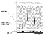
- NaCl-type face center in which a periodic composition change of Ti and Al is present in a cross section of a composite nitride layer or composite carbonitride layer of Ti and Al constituting a hard coating layer corresponding to one embodiment of the present invention
- An example of a graph of periodic composition change x of Ti and Al as a result of performing a line analysis by energy dispersive X-ray spectroscopy (EDS) on a crystal grain having a cubic structure using a transmission electron microscope is shown. Is.
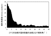
- the ⁇ 111 ⁇ plane which is the crystal plane of the crystal grain with respect to the normal direction of the tool substrate surface
- the inclination angle formed by the normal line is measured, and the inclination angle within the range of 0 to 45 degrees with respect to the normal line direction is divided into every 0.25 degree pitch and exists in each division.
- An example of the inclination angle frequency distribution obtained by counting the frequencies is shown.
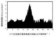
- the method of the ⁇ 111 ⁇ plane which is the crystal plane of the crystal grain with respect to the normal direction of the tool base surface Measures the inclination angle formed by the line, and divides the inclination angle within the range of 0 to 45 degrees with respect to the normal direction among the inclination angles by the pitch of 0.25 degrees and the frequency existing in each section
- An example of the distribution of the number of inclination angles obtained by summing up is shown.
- WC powder, TiC powder, TaC powder, NbC powder, Cr 3 C 2 powder and Co powder all having an average particle diameter of 1 to 3 ⁇ m are prepared, and these raw material powders are blended as shown in Table 1. Blended into the composition, added with wax, mixed in a ball mill in acetone for 24 hours, dried under reduced pressure, pressed into a compact of a predetermined shape at a pressure of 98 MPa, and the compact was 1370 in a vacuum of 5 Pa.
- Mo 2 C powder Mo 2 C powder
- ZrC powder ZrC powder
- NbC powder WC powder
- Co powder all having an average particle diameter of 0.5 to 2 ⁇ m.
- Ni powder are prepared, these raw material powders are blended in the blending composition shown in Table 2, wet mixed by a ball mill for 24 hours, dried, and then pressed into a compact at a pressure of 98 MPa.
- the body was sintered in a nitrogen atmosphere of 1.3 kPa at a temperature of 1500 ° C. for 1 hour, and after sintering, a tool base D made of TiCN-based cermet having an ISO standard SEEN1203AFSN insert shape was produced.
- the Ti and Al composite nitride or composite carbonitride layer constituting the hard coating layer of the inventive coated tool 1 to 15 is applied to a plurality of fields of view using a scanning electron microscope (magnification 5000 times and 20000 times).
- a scanning electron microscope magnification 5000 times and 20000 times.
- the average grain size R of the fine crystal grains is found at three locations having a grain boundary length of 0.5 ⁇ m or more among the grain boundaries of the columnar structure in which the fine crystal grains are found from a plurality of observation fields, and each 0.5 ⁇ m This is obtained by counting the number of grain boundaries existing on the line segment and dividing the total number of grain boundaries at three locations by 1.5 ⁇ m.
- the periodic compositional change of Ti and Al is present in the crystal grains of the NaCl-type face-centered cubic structure, and energy dispersive X-ray spectroscopy using a transmission electron microscope (magnification 200000 times). This was confirmed by surface analysis by the method (EDS). As a result of further detailed analysis, it was confirmed that the difference between the maximum value and the minimum value of the periodic composition change x between Ti and Al was 0.03 to 0.25.
- the (Ti 1-x Al x ) (C y N 1-y ) layer of the reference example is formed on the surfaces of the tool base B and the tool base C by arc ion plating using a conventional physical vapor deposition apparatus.
- the reference coated tool 10 shown in Table 8 was manufactured by vapor-depositing with a target layer thickness.
- the arc ion plating conditions used for the vapor deposition in the reference example are as follows.
- the tool bases B and C are ultrasonically washed in acetone and dried, and the outer periphery is positioned at a predetermined distance in the radial direction from the central axis on the rotary table in the arc ion plating apparatus.
- an Al—Ti alloy having a predetermined composition is arranged as a cathode electrode (evaporation source),
- B First, the inside of the apparatus is evacuated and kept at a vacuum of 10 ⁇ 2 Pa or less, the inside of the apparatus is heated to 500 ° C. with a heater, and then the tool base that rotates while rotating on the rotary table is set to ⁇ 1000 V. A DC bias voltage is applied and a current of 200 A is passed between a cathode electrode and an anode electrode made of an Al—Ti alloy to generate an arc discharge, and Al and Ti ions are generated in the apparatus.
- the cross-sections of the constituent layers of the coated tools 1 to 9, comparative coated tools 1 to 9 and reference coated tool 10 of the present invention in the direction perpendicular to the tool substrate were measured using a scanning electron microscope (5000 times magnification).
- a scanning electron microscope 5000 times magnification.
- the average layer thickness was obtained by measuring and averaging the five layer thicknesses within the observation field, all showed the same average layer thickness as the target layer thicknesses shown in Tables 6 to 8.
- the average content ratio Xavg of Al in the composite nitride or composite carbonitride layer was measured using an electron beam microanalyzer (EPMA, Electron-Probe-Micro-Analyzer) and the surface was polished.
- EPMA electron beam microanalyzer
- the average content ratio Yavg of C indicates an average value in the depth direction of the composite nitride or composite carbonitride layer of Ti and Al.
- the content ratio of C excludes the inevitable content ratio of C that is included without intentionally using a gas containing C as a gas raw material.
- the content ratio (atomic ratio) of the C component contained in the composite nitride or composite carbonitride layer when the supply amount of Al (CH 3 ) 3 is 0 is determined as the inevitable C content ratio.
- the inevitable C content is subtracted from the C component content (atomic ratio) contained in the composite nitride or composite carbonitride layer obtained when Al (CH 3 ) 3 is intentionally supplied. The value was determined as Yavg.
- inventive coated tools 1-9, comparative coated tools 1-9, and reference coated tool 10 a scanning electron microscope (magnification 5000 times and 20000 times) is used from the cross-sectional direction perpendicular to the tool substrate.
- a composite nitride or composite carbonitride layer is formed that has a length of 10 ⁇ m in the horizontal direction with respect to the substrate surface and a thickness less than the thickness of the composite nitride or composite carbonitride layer in the normal direction (Ti 1-x
- the individual crystal grains having a NaCl-type face-centered cubic structure in the Al x ) (C y N 1-y ) layer have a particle width w in a direction parallel to the substrate surface and a particle length in a direction perpendicular to the substrate surface.
- the electric field is applied in a state where the cross section in the direction perpendicular to the tool base surface of the hard coating layer made of a composite nitride or composite carbonitride layer of Ti and Al is a polished surface.
- Cubic crystals that are set in the barrel of an emission scanning electron microscope and exist in the measurement range of the cross-section polished surface with an electron beam with an acceleration voltage of 15 kV at an incident angle of 70 degrees and an irradiation current of 1 nA on the polished surface
- Each crystal grain having a crystal lattice is irradiated, and using an electron backscatter diffraction image apparatus, a length of 100 ⁇ m in the horizontal direction from the tool base surface and a distance equal to or less than the film thickness along a cross section in a direction perpendicular to the tool base surface.
- FIG. 4 shows an inclination angle number distribution measured for the coated tool of the present invention
- FIG. 5 shows an inclination angle number distribution graph measured for the comparative coated tool.
- the coated tools 1 to 9 of the present invention, the comparative coated tools 1 to 9 and the reference coated tool in the state where each of the various coated tools is clamped to the tip of the cutter made of tool steel having a cutter diameter of 125 mm by a fixing jig. No. 10 was subjected to a dry high-speed face milling and center-cut cutting test, which is a kind of high-speed intermittent cutting of alloy steel, and the flank wear width of the cutting edge was measured. The results are shown in Table 9.
- Tool substrate Tungsten carbide-based cemented carbide, titanium carbonitride-based cermet, Cutting test: Dry high-speed face milling, center cutting, Work material: JIS / SCM440 block material with a width of 100 mm and a length of 400 mm, Rotational speed: 968 min ⁇ 1 Cutting speed: 380 m / min, Cutting depth: 1.0 mm, Single-blade feed rate: 0.1 mm / tooth, Cutting time: 8 minutes, (Normal cutting speed is 220 m / min),
- WC powder, TiC powder, ZrC powder, TaC powder, NbC powder, Cr 3 C 2 powder, TiN powder and Co powder each having an average particle diameter of 1 to 3 ⁇ m are prepared.
- Compounded in the formulation shown in Table 10 added with wax, ball mill mixed in acetone for 24 hours, dried under reduced pressure, press-molded into a green compact of a predetermined shape at a pressure of 98 MPa.
- vacuum sintering is performed at a predetermined temperature within a range of 1370 to 1470 ° C. for 1 hour, and after sintering, the cutting edge is subjected to a honing process of R: 0.07 mm.
- Tool bases ⁇ to ⁇ made of WC-base cemented carbide having the insert shape of CNMG120212 were manufactured.
- NbC powder NbC powder
- WC powder Co powder
- Ni powder Ni powder each having an average particle diameter of 0.5 to 2 ⁇ m
- These raw material powders were blended into the composition shown in Table 11, wet mixed with a ball mill for 24 hours, dried, and then pressed into a green compact at a pressure of 98 MPa.
- a chemical vapor deposition apparatus is used on the surfaces of these tool bases ⁇ to ⁇ and tool base ⁇ , and at least (Ti 1-x Al) under the conditions shown in Tables 3 and 4 by the same method as in Example 1.
- the coated tools 11 to 19 of the present invention shown in Table 13 were manufactured by vapor-depositing a hard coating layer including a x ) (C y N 1-y ) layer at a target layer thickness.
- the coated tools 13 to 19 of the present invention either the lower layer or the upper layer shown in Table 12 was formed under the formation conditions shown in Table 3.
- the present invention is also applied to the surfaces of the tool bases ⁇ to ⁇ and the tool base ⁇ by using a normal chemical vapor deposition apparatus under the conditions shown in Tables 3 and 5 and the target layer thicknesses shown in Table 13.
- Comparative coating tools 16 to 28 shown in Table 14 were manufactured by vapor-depositing a hard coating layer in the same manner as the coating tool.
- the coated tools 11 to 19 of the present invention for the comparative coated tools 11 to 19, either the lower layer or the upper layer shown in Table 12 was formed under the formation conditions shown in Table 3.
- the (Ti 1-x Al x ) (C y N 1-y ) layer of the reference example is formed on the surfaces of the tool base ⁇ and the tool base ⁇ by arc ion plating using a conventional physical vapor deposition apparatus.
- the reference coated tool 20 shown in Table 14 was manufactured by vapor-depositing with a target layer thickness.
- the conditions similar to the conditions shown in Example 1 were used for the conditions of arc ion plating.
- each component layer of the inventive coated tool 11 to 19, comparative coated tool 11 to 19 and reference coated tool 20 was measured using a scanning electron microscope (5000 magnifications), and five points within the observation field of view were measured.
- the layer thickness was measured and averaged to determine the average layer thickness, all showed the same average layer thickness as the target layer thicknesses shown in Tables 12-14.
- crystal grains having the NaCl-type face-centered cubic structure with respect to the normal of the substrate surface are measured, and based on this measurement result, the measured tilt angle within the range of 0 to 45 degrees is set to 0.25 of the measured tilt angles.
- the frequencies existing in each division by counting the frequencies existing in each division, the presence of frequency peaks existing in the range of 0 to 10 degrees is confirmed, and in the range of 0 to 10 degrees The percentage of frequencies present was determined.
- Example 1 also shows the average grain size R of the fine crystal grains present in the grain boundary portion of the columnar structure made of crystal grains having the NaCl type face centered cubic structure and the area ratio in which the fine crystal grains exist. It calculated using the method similar to the method. The results are shown in Table 13 and Table 14.
- the Ti and Al composite nitride or composite carbonitride layer constituting the hard coating layer of the coated tools 11 to 19 of the present invention is applied over a plurality of fields using a scanning electron microscope (magnification 5000 times and 20000 times).
- a scanning electron microscope magnification 5000 times and 20000 times.
- a columnar structure composed of individual crystal grains having a cubic structure using an electron beam backscattering diffractometer is used as a composite nitride or composite carbonitride of Ti and Al.
- the fine crystal grains present in the grain boundary part have a hexagonal crystal structure.
- the coated tools 11 to 19 of the present invention, the comparative coated tools 11 to 19 and the reference coated tool 20 with the various coated tools screwed to the tip of the tool steel tool with a fixing jig The dry high-speed intermittent cutting test of carbon steel and the wet high-speed intermittent cutting test of cast iron shown below were carried out, and both measured the flank wear width of the cutting edge.
- Cutting condition 1 Work material: JIS ⁇ SCM435 lengthwise equally spaced four round grooved round bars, Cutting speed: 380 m / min, Cutting depth: 1.5 mm, Feed: 0.2 mm / rev, Cutting time: 5 minutes, (Normal cutting speed is 220 m / min),
- Cutting condition 2 Work material: JIS / FCD700 lengthwise equal length 4 round bar with round groove, Cutting speed: 320 m / min, Cutting depth: 1.0 mm, Feed: 0.2 mm / rev, Cutting time: 5 minutes (Normal cutting speed is 180 m / min), Table 15 shows the results of the cutting test.
- cBN powder, TiN powder, TiCN powder, TiC powder, Al powder, and Al 2 O 3 powder each having an average particle diameter in the range of 0.5 to 4 ⁇ m were prepared.
- the mixture is blended in the composition shown in FIG. 1, wet mixed with a ball mill for 80 hours, dried, and then pressed into a green compact having a diameter of 50 mm ⁇ thickness: 1.5 mm under a pressure of 120 MPa.
- the green compact is sintered in a vacuum atmosphere at a pressure of 1 Pa at a predetermined temperature in the range of 900 to 1300 ° C. for 60 minutes to obtain a presintered body for a cutting edge piece.
- Co 8% by mass
- WC remaining composition
- diameter 50 mm ⁇ thickness: 2 mm
- a certain pressure 4 GPa
- temperature a predetermined temperature within the range of 1200 to 1400 ° C., holding at a high pressure under a condition of holding time: 0.8 hour
- wire discharge It is divided into predetermined dimensions by a processing apparatus, and further Co: 5 mass%, TaC: 5 mass%, WC: remaining composition and shape of JIS standard CNGA12041 (thickness: 4.76 mm ⁇ inscribed circle diameter: 12.
- the brazing part (corner part) of the WC-based cemented carbide insert body having a 7 mm 80 ° rhombus) has a composition consisting of Zr: 37.5%, Cu: 25%, Ti: the rest in mass%.
- the cutting edge portion is subjected to honing with a width of 0.13 mm and an angle of 25 °, and further subjected to finish polishing.
- ISO regulations CNGA120412 tool substrate b having the insert shape, were manufactured, respectively b.
- a conventional chemical vapor deposition apparatus is used on the surfaces of the tool bases i and b, and at least (Ti 1-x Al x ) (C y N 1 ) under the conditions shown in Tables 3 and 5.
- Comparative coating tools 21 to 24 shown in Table 19 were manufactured by vapor-depositing a hard coating layer including a -y ) layer at a target layer thickness.
- the comparative coated tools 22 to 24 were formed with either the lower layer or the upper layer as shown in Table 17 under the formation conditions shown in Table 3.
- the (Ti 1-x Al x ) (C y N 1-y ) layer is formed at the target layer thickness on the surfaces of the tool bases i and b by arc ion plating using a conventional physical vapor deposition apparatus.
- a reference coated tool 25 shown in Table 19 was manufactured by vapor deposition.
- the arc ion plating conditions are the same as those shown in Example 1, and the (Al, Ti) N layer having the target composition and target layer thickness shown in Table 19 is formed on the surface of the tool base.
- the reference coating tool 25 was manufactured by vapor deposition.
- crystal grains having the NaCl-type face-centered cubic structure with respect to the normal of the substrate surface are measured, and based on this measurement result, the measured tilt angle within the range of 0 to 45 degrees is set to 0.25 of the measured tilt angles.
- the frequencies existing in each division by counting the frequencies existing in each division, the presence of frequency peaks existing in the range of 0 to 10 degrees is confirmed, and in the range of 0 to 10 degrees The percentage of frequencies present was determined.
- Example 1 also shows the average grain size R of the fine crystal grains present in the grain boundary portion of the columnar structure made of crystal grains having the NaCl type face centered cubic structure and the area ratio in which the fine crystal grains exist. It calculated using the method similar to the method. The results are shown in Table 18 and Table 19.
- Tool substrate Cubic boron nitride based ultra-high pressure sintered body
- Cutting test Dry high-speed intermittent cutting of carburized and quenched alloy steel
- Work material JIS ⁇ SCr420 (Hardness: HRC62) lengthwise equidistant four round bars with vertical grooves
- Cutting speed 240 m / min
- Cutting depth 0.12 mm
- Feed 0.1 mm / rev
- Cutting time 4 minutes
- Table 20 shows the results of the cutting test.
- the coated tool of the present invention has a face-centered cubic structure of NaCl type that constitutes a composite nitride of Ti and Al or a composite carbonitride layer constituting the hard coating layer.
- the periodic compositional change of Ti and Al is present in the crystal grains, so that strain is generated in the crystal grains, the hardness is improved, and the columnar structure is used, so At the same time as exhibiting wear properties, the presence of hexagonal crystal grains at the grain boundaries of the columnar structure prevents grain boundary sliding, improves toughness, and further improves the NaCl-type face-centered cubic structure.
- the flank wear resistance and crater wear resistance improved, respectively. Even when chipping resistance Excellent chipping resistance, it is apparent that exhibits excellent wear resistance over a long-term use.
- the comparative coated tools 1 to 9, 10 to 19, 21 to 24 and the reference coated tools 10, 20, and 25 are accompanied by high heat generation, and an intermittent and impact high load acts on the cutting edge.
- an intermittent and impact high load acts on the cutting edge.
- the coated tool of the present invention can be used not only for high-speed intermittent cutting of alloy steel but also as a coated tool for various work materials, and has excellent chipping resistance over a long period of use. Since it exhibits wear resistance, it can sufficiently satisfy the high performance of the cutting device, the labor saving and energy saving of the cutting work, and the cost reduction.
Landscapes
- Chemical & Material Sciences (AREA)
- Engineering & Computer Science (AREA)
- Mechanical Engineering (AREA)
- Chemical Kinetics & Catalysis (AREA)
- Materials Engineering (AREA)
- Metallurgy (AREA)
- Organic Chemistry (AREA)
- Inorganic Chemistry (AREA)
- General Chemical & Material Sciences (AREA)
- Ceramic Engineering (AREA)
- Chemical Vapour Deposition (AREA)
- Cutting Tools, Boring Holders, And Turrets (AREA)
Priority Applications (4)
| Application Number | Priority Date | Filing Date | Title |
|---|---|---|---|
| EP15843784.8A EP3103572B1 (en) | 2014-09-25 | 2015-09-18 | Surface-coated cutting tool in which hard coating layer exhibits excellent chipping resistance |
| US15/509,725 US10456842B2 (en) | 2014-09-25 | 2015-09-18 | Surface-coated cutting tool in which hard coating layer exhibits excellent chipping resistance |
| CN201580028086.1A CN106457413B (zh) | 2014-09-25 | 2015-09-18 | 硬质包覆层发挥优异的耐崩刀性的表面包覆切削工具 |
| KR1020177010485A KR20170057375A (ko) | 2014-09-25 | 2015-09-18 | 경질 피복층이 우수한 내치핑성을 발휘하는 표면 피복 절삭 공구 |
Applications Claiming Priority (2)
| Application Number | Priority Date | Filing Date | Title |
|---|---|---|---|
| JP2014195795A JP5924507B2 (ja) | 2014-09-25 | 2014-09-25 | 硬質被覆層がすぐれた耐チッピング性を発揮する表面被覆切削工具 |
| JP2014-195795 | 2014-09-25 |
Publications (1)
| Publication Number | Publication Date |
|---|---|
| WO2016047581A1 true WO2016047581A1 (ja) | 2016-03-31 |
Family
ID=55581108
Family Applications (1)
| Application Number | Title | Priority Date | Filing Date |
|---|---|---|---|
| PCT/JP2015/076645 WO2016047581A1 (ja) | 2014-09-25 | 2015-09-18 | 硬質被覆層がすぐれた耐チッピング性を発揮する表面被覆切削工具 |
Country Status (6)
Cited By (7)
| Publication number | Priority date | Publication date | Assignee | Title |
|---|---|---|---|---|
| WO2017175400A1 (ja) * | 2016-04-08 | 2017-10-12 | 住友電工ハードメタル株式会社 | 表面被覆切削工具およびその製造方法 |
| JP2017189846A (ja) * | 2016-04-14 | 2017-10-19 | 住友電工ハードメタル株式会社 | 表面被覆切削工具およびその製造方法 |
| JP2017189847A (ja) * | 2016-04-14 | 2017-10-19 | 住友電工ハードメタル株式会社 | 表面被覆切削工具およびその製造方法 |
| JP2017189848A (ja) * | 2016-04-14 | 2017-10-19 | 住友電工ハードメタル株式会社 | 表面被覆切削工具およびその製造方法 |
| JPWO2018047733A1 (ja) * | 2016-09-06 | 2019-06-24 | 住友電工ハードメタル株式会社 | 切削工具およびその製造方法 |
| US11220760B2 (en) | 2016-04-14 | 2022-01-11 | Sumitomo Electric Hardmetal Corp. | Surface-coated cutting tool and method of producing the same |
| CN115038811A (zh) * | 2020-02-28 | 2022-09-09 | 山特维克科洛曼特公司 | 涂层切削工具 |
Families Citing this family (37)
| Publication number | Priority date | Publication date | Assignee | Title |
|---|---|---|---|---|
| JP6120229B2 (ja) * | 2015-01-14 | 2017-04-26 | 住友電工ハードメタル株式会社 | 硬質被膜、切削工具および硬質被膜の製造方法 |
| JP6709536B2 (ja) * | 2015-05-26 | 2020-06-17 | 三菱マテリアル株式会社 | 硬質被覆層がすぐれた耐チッピング性を発揮する表面被覆切削工具 |
| WO2016190332A1 (ja) * | 2015-05-26 | 2016-12-01 | 三菱マテリアル株式会社 | 硬質被覆層がすぐれた耐チッピング性を発揮する表面被覆切削工具 |
| ES2714791T3 (es) | 2016-07-01 | 2019-05-30 | Walter Ag | Herramienta de corte con capa de alúmina texturizada |
| JP6481897B2 (ja) * | 2016-09-16 | 2019-03-13 | 三菱マテリアル株式会社 | 表面被覆切削工具 |
| JP6667713B2 (ja) | 2017-02-28 | 2020-03-18 | 住友電工ハードメタル株式会社 | 表面被覆切削工具およびその製造方法 |
| WO2018158974A1 (ja) | 2017-02-28 | 2018-09-07 | 住友電工ハードメタル株式会社 | 表面被覆切削工具およびその製造方法 |
| CN110382145B (zh) * | 2017-02-28 | 2021-09-21 | 住友电工硬质合金株式会社 | 表面被覆切削工具及其制造方法 |
| JP7068646B2 (ja) * | 2017-03-08 | 2022-05-17 | 三菱マテリアル株式会社 | 表面被覆切削工具 |
| JP2018164960A (ja) * | 2017-03-28 | 2018-10-25 | 三菱マテリアル株式会社 | 高耐欠損性を有する被覆超硬合金工具 |
| JP6858346B2 (ja) * | 2017-06-26 | 2021-04-14 | 三菱マテリアル株式会社 | 硬質被覆層が優れた耐チッピング性を発揮する表面被覆切削工具 |
| WO2019006361A1 (en) * | 2017-06-30 | 2019-01-03 | Hyperloop Technologies, Inc. | ACTIVE CONTROL SYSTEM |
| JP7191287B2 (ja) * | 2018-03-20 | 2022-12-19 | 三菱マテリアル株式会社 | 硬質被覆層が優れた耐チッピング性を発揮する表面被覆切削工具 |
| CN108796441B (zh) * | 2018-06-06 | 2020-03-03 | 中国科学院宁波材料技术与工程研究所 | 一种光吸收镀膜、其制备方法及应用 |
| JP7231885B2 (ja) * | 2018-09-28 | 2023-03-02 | 三菱マテリアル株式会社 | 硬質被覆層が優れた耐チッピング性を発揮する表面被覆切削工具 |
| JP6810123B2 (ja) | 2018-12-18 | 2021-01-06 | リンテック株式会社 | 粘着シート、表示体および表示体の製造方法 |
| JP7274121B2 (ja) * | 2019-03-05 | 2023-05-16 | 三菱マテリアル株式会社 | 硬質被覆層がすぐれた耐摩耗性および耐剥離性を発揮する表面被覆切削工具 |
| JP7190111B2 (ja) * | 2019-03-19 | 2022-12-15 | 三菱マテリアル株式会社 | 表面被覆切削工具 |
| JP6792662B2 (ja) | 2019-03-29 | 2020-11-25 | リンテック株式会社 | 着色粘着シートおよび表示体 |
| JP6880134B2 (ja) | 2019-09-20 | 2021-06-02 | リンテック株式会社 | 表示体 |
| WO2020213259A1 (ja) * | 2019-04-17 | 2020-10-22 | 住友電工ハードメタル株式会社 | 切削工具 |
| JP6750789B1 (ja) * | 2019-04-17 | 2020-09-02 | 住友電工ハードメタル株式会社 | 切削工具 |
| WO2020213257A1 (ja) * | 2019-04-17 | 2020-10-22 | 住友電工ハードメタル株式会社 | 切削工具 |
| WO2020213258A1 (ja) * | 2019-04-17 | 2020-10-22 | 住友電工ハードメタル株式会社 | 切削工具 |
| JP6937338B2 (ja) | 2019-05-27 | 2021-09-22 | リンテック株式会社 | 表示体および粘着シート |
| US20220320527A1 (en) * | 2019-07-24 | 2022-10-06 | National Institute Of Advanced Industrial Science And Technology | Electrode having columnar structure provided with multilayer part |
| JP7329180B2 (ja) | 2020-02-03 | 2023-08-18 | 三菱マテリアル株式会社 | 表面被覆切削工具 |
| JP7082150B2 (ja) | 2020-03-11 | 2022-06-07 | リンテック株式会社 | 飛散防止粘着シートおよび表示体 |
| JP7510108B2 (ja) * | 2020-03-17 | 2024-07-03 | 三菱マテリアル株式会社 | 表面被覆切削工具 |
| JP7437623B2 (ja) * | 2020-03-27 | 2024-02-26 | 三菱マテリアル株式会社 | 硬質被覆層がすぐれた耐チッピング性を発揮する表面被覆切削工具 |
| KR20230115984A (ko) * | 2020-12-03 | 2023-08-03 | 발터 악티엔게젤샤프트 | 교대 층 조성을 갖는 코팅된 절삭 공구 |
| JP7610781B2 (ja) * | 2021-03-23 | 2025-01-09 | 三菱マテリアル株式会社 | 表面被覆切削工具 |
| JP7610782B2 (ja) * | 2021-03-23 | 2025-01-09 | 三菱マテリアル株式会社 | 表面被覆切削工具 |
| EP4330443A1 (en) * | 2021-04-30 | 2024-03-06 | Walter Ag | A coated cutting tool |
| JP7533344B2 (ja) * | 2021-04-30 | 2024-08-14 | 住友電気工業株式会社 | 切削工具 |
| EP4501501A1 (en) * | 2022-03-30 | 2025-02-05 | Mitsubishi Materials Corporation | Surface-coated cutting tool |
| EP4610393A1 (de) * | 2024-02-28 | 2025-09-03 | BOEHLERIT GmbH & Co.KG. | Verfahren zum beschichten eines objektes und damit hergestelltes objekt |
Citations (6)
| Publication number | Priority date | Publication date | Assignee | Title |
|---|---|---|---|---|
| JP2010094763A (ja) * | 2008-10-15 | 2010-04-30 | Mitsubishi Materials Corp | 硬質被覆層がすぐれた耐欠損性、耐摩耗性を発揮する表面被覆切削工具 |
| JP2014024130A (ja) * | 2012-07-25 | 2014-02-06 | Mitsubishi Materials Corp | 高速断続切削加工で硬質被覆層がすぐれた耐チッピング性を発揮する表面被覆切削工具 |
| JP2014133267A (ja) * | 2013-01-08 | 2014-07-24 | Mitsubishi Materials Corp | 硬質被覆層がすぐれた耐酸化性、耐チッピング性、耐摩耗性を発揮する表面被覆切削工具 |
| JP2015157351A (ja) * | 2014-01-22 | 2015-09-03 | 三菱マテリアル株式会社 | 硬質被覆層がすぐれた耐チッピング性を発揮する表面被覆切削工具 |
| JP2015163423A (ja) * | 2014-01-31 | 2015-09-10 | 三菱マテリアル株式会社 | 高速断続切削加工で硬質被覆層がすぐれた耐チッピング性を発揮する表面被覆切削工具 |
| WO2015147160A1 (ja) * | 2014-03-26 | 2015-10-01 | 三菱マテリアル株式会社 | 表面被覆切削工具及びその製造方法 |
Family Cites Families (12)
| Publication number | Priority date | Publication date | Assignee | Title |
|---|---|---|---|---|
| JP2000144376A (ja) | 1998-11-18 | 2000-05-26 | Sumitomo Electric Ind Ltd | 摺動特性の良好な皮膜 |
| DE102008013966A1 (de) | 2008-03-12 | 2009-09-17 | Kennametal Inc. | Hartstoffbeschichteter Körper |
| DE102008013965A1 (de) | 2008-03-12 | 2009-09-17 | Kennametal Inc. | Hartstoffbeschichteter Körper |
| EP2604720A1 (en) * | 2011-12-14 | 2013-06-19 | Sandvik Intellectual Property Ab | Coated cutting tool and method of manufacturing the same |
| JP6024981B2 (ja) | 2012-03-09 | 2016-11-16 | 三菱マテリアル株式会社 | 高速断続切削加工で硬質被覆層がすぐれた耐チッピング性を発揮する表面被覆切削工具 |
| JP5939509B2 (ja) * | 2012-07-25 | 2016-06-22 | 三菱マテリアル株式会社 | 高速断続切削加工で硬質被覆層がすぐれた耐チッピング性を発揮する表面被覆切削工具 |
| US9476114B2 (en) | 2012-08-03 | 2016-10-25 | Walter Ag | TiAlN-coated tool |
| DE102012107129A1 (de) * | 2012-08-03 | 2014-02-06 | Walter Ag | TiAIN-beschichtetes Werkzeug |
| JP6090063B2 (ja) * | 2012-08-28 | 2017-03-08 | 三菱マテリアル株式会社 | 表面被覆切削工具 |
| JP5892473B2 (ja) * | 2012-09-13 | 2016-03-23 | 三菱マテリアル株式会社 | 硬質被覆層が高速断続切削加工ですぐれた耐剥離性、耐チッピング性を発揮する表面被覆切削工具 |
| JP6037113B2 (ja) * | 2012-11-13 | 2016-11-30 | 三菱マテリアル株式会社 | 高速断続切削加工で硬質被覆層がすぐれた耐チッピング性を発揮する表面被覆切削工具 |
| JP6044336B2 (ja) * | 2012-12-27 | 2016-12-14 | 三菱マテリアル株式会社 | 硬質被覆層がすぐれた耐チッピング性を発揮する表面被覆切削工具 |
-
2014
- 2014-09-25 JP JP2014195795A patent/JP5924507B2/ja active Active
-
2015
- 2015-09-18 CN CN201580028086.1A patent/CN106457413B/zh active Active
- 2015-09-18 US US15/509,725 patent/US10456842B2/en active Active
- 2015-09-18 WO PCT/JP2015/076645 patent/WO2016047581A1/ja active Application Filing
- 2015-09-18 EP EP15843784.8A patent/EP3103572B1/en active Active
- 2015-09-18 KR KR1020177010485A patent/KR20170057375A/ko not_active Withdrawn
Patent Citations (6)
| Publication number | Priority date | Publication date | Assignee | Title |
|---|---|---|---|---|
| JP2010094763A (ja) * | 2008-10-15 | 2010-04-30 | Mitsubishi Materials Corp | 硬質被覆層がすぐれた耐欠損性、耐摩耗性を発揮する表面被覆切削工具 |
| JP2014024130A (ja) * | 2012-07-25 | 2014-02-06 | Mitsubishi Materials Corp | 高速断続切削加工で硬質被覆層がすぐれた耐チッピング性を発揮する表面被覆切削工具 |
| JP2014133267A (ja) * | 2013-01-08 | 2014-07-24 | Mitsubishi Materials Corp | 硬質被覆層がすぐれた耐酸化性、耐チッピング性、耐摩耗性を発揮する表面被覆切削工具 |
| JP2015157351A (ja) * | 2014-01-22 | 2015-09-03 | 三菱マテリアル株式会社 | 硬質被覆層がすぐれた耐チッピング性を発揮する表面被覆切削工具 |
| JP2015163423A (ja) * | 2014-01-31 | 2015-09-10 | 三菱マテリアル株式会社 | 高速断続切削加工で硬質被覆層がすぐれた耐チッピング性を発揮する表面被覆切削工具 |
| WO2015147160A1 (ja) * | 2014-03-26 | 2015-10-01 | 三菱マテリアル株式会社 | 表面被覆切削工具及びその製造方法 |
Cited By (31)
| Publication number | Priority date | Publication date | Assignee | Title |
|---|---|---|---|---|
| WO2017175400A1 (ja) * | 2016-04-08 | 2017-10-12 | 住友電工ハードメタル株式会社 | 表面被覆切削工具およびその製造方法 |
| JP2017185610A (ja) * | 2016-04-08 | 2017-10-12 | 住友電工ハードメタル株式会社 | 表面被覆切削工具およびその製造方法 |
| EP3415255A4 (en) * | 2016-04-08 | 2019-04-03 | Sumitomo Electric Hardmetal Corp. | SURFACE-CUTTED CUTTING TOOL AND METHOD FOR THE PRODUCTION THEREOF |
| US10166611B2 (en) | 2016-04-08 | 2019-01-01 | Sumitomo Electric Hardmetal Corp. | Surface-coated cutting tool and method of producing the same |
| US20180178294A1 (en) | 2016-04-08 | 2018-06-28 | Sumitomo Electric Hardmetal Corp. | Surface-coated cutting tool and method of producing the same |
| WO2017179220A1 (ja) * | 2016-04-14 | 2017-10-19 | 住友電工ハードメタル株式会社 | 表面被覆切削工具およびその製造方法 |
| US20190151956A1 (en) * | 2016-04-14 | 2019-05-23 | Sumitomo Electric Hardmetal Corp. | Surface-coated cutting tool and method of producing the same |
| WO2017179218A1 (ja) * | 2016-04-14 | 2017-10-19 | 住友電工ハードメタル株式会社 | 表面被覆切削工具およびその製造方法 |
| CN107438490A (zh) * | 2016-04-14 | 2017-12-05 | 住友电工硬质合金株式会社 | 表面被覆切削工具及其制造方法 |
| CN107530785A (zh) * | 2016-04-14 | 2018-01-02 | 住友电工硬质合金株式会社 | 表面被覆切削工具及其制造方法 |
| JP2017189848A (ja) * | 2016-04-14 | 2017-10-19 | 住友電工ハードメタル株式会社 | 表面被覆切削工具およびその製造方法 |
| KR20180123092A (ko) * | 2016-04-14 | 2018-11-14 | 스미또모 덴꼬오 하드메탈 가부시끼가이샤 | 표면 피복 절삭 공구 및 그 제조 방법 |
| CN109070234A (zh) * | 2016-04-14 | 2018-12-21 | 住友电工硬质合金株式会社 | 表面被覆切削工具及其制造方法 |
| KR20180135497A (ko) * | 2016-04-14 | 2018-12-21 | 스미또모 덴꼬오 하드메탈 가부시끼가이샤 | 표면 피복 절삭 공구 및 그 제조 방법 |
| JP2017189847A (ja) * | 2016-04-14 | 2017-10-19 | 住友電工ハードメタル株式会社 | 表面被覆切削工具およびその製造方法 |
| JP2017189846A (ja) * | 2016-04-14 | 2017-10-19 | 住友電工ハードメタル株式会社 | 表面被覆切削工具およびその製造方法 |
| US10252343B2 (en) | 2016-04-14 | 2019-04-09 | Sumitomo Electric Hardmetal Corp. | Surface-coated cutting tool and method of producing the same |
| US10259048B2 (en) | 2016-04-14 | 2019-04-16 | Sumitomo Electric Hardmetal Corp. | Surface-coated cutting tool and method of producing the same |
| WO2017179221A1 (ja) * | 2016-04-14 | 2017-10-19 | 住友電工ハードメタル株式会社 | 表面被覆切削工具およびその製造方法 |
| US11220760B2 (en) | 2016-04-14 | 2022-01-11 | Sumitomo Electric Hardmetal Corp. | Surface-coated cutting tool and method of producing the same |
| KR102259274B1 (ko) | 2016-04-14 | 2021-05-31 | 스미또모 덴꼬오 하드메탈 가부시끼가이샤 | 표면 피복 절삭 공구 및 그 제조 방법 |
| EP3444053A4 (en) * | 2016-04-14 | 2019-10-09 | Sumitomo Electric Hardmetal Corp. | SURFACE-COATED CUTTING TOOL AND MANUFACTURING METHOD THEREFOR |
| EP3412386A4 (en) * | 2016-04-14 | 2019-10-09 | Sumitomo Electric Hardmetal Corp. | SURFACE-COATED CUTTING TOOL AND MANUFACTURING METHOD THEREFOR |
| EP3444052A4 (en) * | 2016-04-14 | 2019-10-16 | Sumitomo Electric Hardmetal Corp. | SURFACE-COATED CUTTING TOOL AND MANUFACTURING METHOD THEREFOR |
| CN107530785B (zh) * | 2016-04-14 | 2020-04-21 | 住友电工硬质合金株式会社 | 表面被覆切削工具及其制造方法 |
| US10953473B2 (en) | 2016-04-14 | 2021-03-23 | Sumitomo Electric Hardmetal Corp. | Surface-coated cutting tool and method of producing the same |
| KR102198745B1 (ko) * | 2016-04-14 | 2021-01-05 | 스미또모 덴꼬오 하드메탈 가부시끼가이샤 | 표면 피복 절삭 공구 및 그 제조 방법 |
| EP3511097A4 (en) * | 2016-09-06 | 2020-05-13 | Sumitomo Electric Hardmetal Corp. | CUTTING TOOL AND METHOD FOR PRODUCING THE SAME |
| US20190232386A1 (en) * | 2016-09-06 | 2019-08-01 | Sumitomo Electric Hardmetal Corp. | Cutting Tool and Method for Manufacturing Same |
| JPWO2018047733A1 (ja) * | 2016-09-06 | 2019-06-24 | 住友電工ハードメタル株式会社 | 切削工具およびその製造方法 |
| CN115038811A (zh) * | 2020-02-28 | 2022-09-09 | 山特维克科洛曼特公司 | 涂层切削工具 |
Also Published As
| Publication number | Publication date |
|---|---|
| CN106457413A (zh) | 2017-02-22 |
| KR20170057375A (ko) | 2017-05-24 |
| JP2016064485A (ja) | 2016-04-28 |
| EP3103572B1 (en) | 2018-11-21 |
| US10456842B2 (en) | 2019-10-29 |
| JP5924507B2 (ja) | 2016-05-25 |
| US20170297117A1 (en) | 2017-10-19 |
| CN106457413B (zh) | 2019-05-07 |
| EP3103572A1 (en) | 2016-12-14 |
| EP3103572A4 (en) | 2017-07-26 |
Similar Documents
| Publication | Publication Date | Title |
|---|---|---|
| JP5924507B2 (ja) | 硬質被覆層がすぐれた耐チッピング性を発揮する表面被覆切削工具 | |
| JP6402662B2 (ja) | 表面被覆切削工具及びその製造方法 | |
| JP6478100B2 (ja) | 硬質被覆層がすぐれた耐チッピング性を発揮する表面被覆切削工具 | |
| JP6268530B2 (ja) | 硬質被覆層がすぐれた耐チッピング性を発揮する表面被覆切削工具 | |
| JP6284034B2 (ja) | 硬質被覆層がすぐれた耐チッピング性を発揮する表面被覆切削工具 | |
| JP6296294B2 (ja) | 硬質被覆層がすぐれた耐チッピング性を発揮する表面被覆切削工具 | |
| JP6394898B2 (ja) | 高速断続切削加工で硬質被覆層がすぐれた耐チッピング性を発揮する表面被覆切削工具 | |
| JP6090063B2 (ja) | 表面被覆切削工具 | |
| JP6417959B2 (ja) | 硬質被覆層がすぐれた耐チッピング性を発揮する表面被覆切削工具 | |
| JP6548071B2 (ja) | 硬質被覆層がすぐれた耐チッピング性を発揮する表面被覆切削工具 | |
| JP6391045B2 (ja) | 高速断続切削加工で硬質被覆層がすぐれた耐チッピング性を発揮する表面被覆切削工具 | |
| JP6548073B2 (ja) | 硬質被覆層がすぐれた耐チッピング性を発揮する表面被覆切削工具 | |
| JP6150109B2 (ja) | 硬質被覆層がすぐれた耐チッピング性を発揮する表面被覆切削工具 | |
| JP2014097536A (ja) | 高速断続切削加工で硬質被覆層がすぐれた耐チッピング性を発揮する表面被覆切削工具 | |
| JP2017030076A (ja) | 硬質被覆層がすぐれた耐チッピング性を発揮する表面被覆切削工具 | |
| WO2016148056A1 (ja) | 硬質被覆層がすぐれた耐チッピング性を発揮する表面被覆切削工具 | |
| JP6617917B2 (ja) | 表面被覆切削工具 | |
| JP2016083766A (ja) | 表面被覆切削工具 | |
| JP2017080884A (ja) | 硬質被覆層がすぐれた耐摩耗性および耐チッピング性を発揮する表面被覆切削工具 | |
| JP6171800B2 (ja) | 硬質被覆層がすぐれた耐チッピング性を発揮する表面被覆切削工具 | |
| WO2017038840A1 (ja) | 硬質被覆層がすぐれた耐チッピング性を発揮する表面被覆切削工具 | |
| JP2017080882A (ja) | 硬質被覆層がすぐれた耐摩耗性および耐チッピング性を発揮する表面被覆切削工具 | |
| WO2016084938A1 (ja) | 表面被覆切削工具 | |
| WO2016068122A1 (ja) | 表面被覆切削工具 | |
| WO2017073790A1 (ja) | 表面被覆切削工具およびその製造方法 |
Legal Events
| Date | Code | Title | Description |
|---|---|---|---|
| 121 | Ep: the epo has been informed by wipo that ep was designated in this application |
Ref document number: 15843784 Country of ref document: EP Kind code of ref document: A1 |
|
| REEP | Request for entry into the european phase |
Ref document number: 2015843784 Country of ref document: EP |
|
| WWE | Wipo information: entry into national phase |
Ref document number: 2015843784 Country of ref document: EP |
|
| WWE | Wipo information: entry into national phase |
Ref document number: 15509725 Country of ref document: US |
|
| NENP | Non-entry into the national phase |
Ref country code: DE |
|
| ENP | Entry into the national phase |
Ref document number: 20177010485 Country of ref document: KR Kind code of ref document: A |