EP3103572A1 - Surface-coated cutting tool in which hard coating layer exhibits excellent chipping resistance - Google Patents
Surface-coated cutting tool in which hard coating layer exhibits excellent chipping resistance Download PDFInfo
- Publication number
- EP3103572A1 EP3103572A1 EP15843784.8A EP15843784A EP3103572A1 EP 3103572 A1 EP3103572 A1 EP 3103572A1 EP 15843784 A EP15843784 A EP 15843784A EP 3103572 A1 EP3103572 A1 EP 3103572A1
- Authority
- EP
- European Patent Office
- Prior art keywords
- layer
- complex
- average
- crystal grains
- carbonitride
- Prior art date
- Legal status (The legal status is an assumption and is not a legal conclusion. Google has not performed a legal analysis and makes no representation as to the accuracy of the status listed.)
- Granted
Links
- 238000005520 cutting process Methods 0.000 title claims abstract description 88
- 239000011247 coating layer Substances 0.000 title claims abstract description 61
- 239000010410 layer Substances 0.000 claims abstract description 291
- 239000013078 crystal Substances 0.000 claims abstract description 158
- FAPWRFPIFSIZLT-UHFFFAOYSA-M Sodium chloride Chemical compound [Na+].[Cl-] FAPWRFPIFSIZLT-UHFFFAOYSA-M 0.000 claims abstract description 152
- 229910052719 titanium Inorganic materials 0.000 claims abstract description 89
- 229910052782 aluminium Inorganic materials 0.000 claims abstract description 85
- 239000011780 sodium chloride Substances 0.000 claims abstract description 76
- 239000000203 mixture Substances 0.000 claims abstract description 42
- 230000000737 periodic effect Effects 0.000 claims abstract description 34
- 239000010936 titanium Substances 0.000 claims description 117
- 150000004767 nitrides Chemical class 0.000 claims description 109
- 238000000034 method Methods 0.000 claims description 34
- ATJFFYVFTNAWJD-UHFFFAOYSA-N Tin Chemical compound [Sn] ATJFFYVFTNAWJD-UHFFFAOYSA-N 0.000 claims description 32
- 238000009826 distribution Methods 0.000 claims description 31
- JLTRXTDYQLMHGR-UHFFFAOYSA-N trimethylaluminium Chemical compound C[Al](C)C JLTRXTDYQLMHGR-UHFFFAOYSA-N 0.000 claims description 27
- 230000008859 change Effects 0.000 claims description 21
- 238000005229 chemical vapour deposition Methods 0.000 claims description 17
- 239000012495 reaction gas Substances 0.000 claims description 17
- 238000001887 electron backscatter diffraction Methods 0.000 claims description 9
- 229910052757 nitrogen Inorganic materials 0.000 claims description 7
- 238000002441 X-ray diffraction Methods 0.000 claims description 6
- 230000004931 aggregating effect Effects 0.000 claims description 6
- 229910052799 carbon Inorganic materials 0.000 claims description 6
- 239000011195 cermet Substances 0.000 claims description 6
- 150000001875 compounds Chemical class 0.000 claims description 5
- 229910052582 BN Inorganic materials 0.000 claims description 4
- PZNSFCLAULLKQX-UHFFFAOYSA-N Boron nitride Chemical compound N#B PZNSFCLAULLKQX-UHFFFAOYSA-N 0.000 claims description 4
- RTAQQCXQSZGOHL-UHFFFAOYSA-N Titanium Chemical compound [Ti] RTAQQCXQSZGOHL-UHFFFAOYSA-N 0.000 claims description 4
- TWNQGVIAIRXVLR-UHFFFAOYSA-N oxo(oxoalumanyloxy)alumane Chemical compound O=[Al]O[Al]=O TWNQGVIAIRXVLR-UHFFFAOYSA-N 0.000 claims description 4
- UONOETXJSWQNOL-UHFFFAOYSA-N tungsten carbide Chemical compound [W+]#[C-] UONOETXJSWQNOL-UHFFFAOYSA-N 0.000 claims description 4
- 230000007547 defect Effects 0.000 abstract description 14
- 230000007774 longterm Effects 0.000 abstract description 12
- 239000011248 coating agent Substances 0.000 abstract description 9
- 238000000576 coating method Methods 0.000 abstract description 9
- 239000007789 gas Substances 0.000 description 63
- VSCWAEJMTAWNJL-UHFFFAOYSA-K aluminium trichloride Chemical compound Cl[Al](Cl)Cl VSCWAEJMTAWNJL-UHFFFAOYSA-K 0.000 description 41
- 239000000843 powder Substances 0.000 description 40
- 230000000052 comparative effect Effects 0.000 description 30
- 229910003074 TiCl4 Inorganic materials 0.000 description 28
- XJDNKRIXUMDJCW-UHFFFAOYSA-J titanium tetrachloride Chemical compound Cl[Ti](Cl)(Cl)Cl XJDNKRIXUMDJCW-UHFFFAOYSA-J 0.000 description 28
- 238000006243 chemical reaction Methods 0.000 description 14
- 239000002994 raw material Substances 0.000 description 14
- 230000015572 biosynthetic process Effects 0.000 description 13
- 238000002156 mixing Methods 0.000 description 12
- 230000008569 process Effects 0.000 description 12
- 229910000851 Alloy steel Inorganic materials 0.000 description 11
- PNEYBMLMFCGWSK-UHFFFAOYSA-N aluminium oxide Inorganic materials [O-2].[O-2].[O-2].[Al+3].[Al+3] PNEYBMLMFCGWSK-UHFFFAOYSA-N 0.000 description 11
- 239000012298 atmosphere Substances 0.000 description 11
- 229910052593 corundum Inorganic materials 0.000 description 11
- 230000000694 effects Effects 0.000 description 11
- 230000006872 improvement Effects 0.000 description 11
- 229910001845 yogo sapphire Inorganic materials 0.000 description 11
- 230000007423 decrease Effects 0.000 description 10
- 238000000151 deposition Methods 0.000 description 9
- 238000002149 energy-dispersive X-ray emission spectroscopy Methods 0.000 description 9
- 238000004458 analytical method Methods 0.000 description 8
- 238000007733 ion plating Methods 0.000 description 8
- 238000005245 sintering Methods 0.000 description 7
- CSCPPACGZOOCGX-UHFFFAOYSA-N Acetone Chemical compound CC(C)=O CSCPPACGZOOCGX-UHFFFAOYSA-N 0.000 description 6
- 239000000463 material Substances 0.000 description 6
- 238000005259 measurement Methods 0.000 description 6
- 230000000007 visual effect Effects 0.000 description 6
- 238000005240 physical vapour deposition Methods 0.000 description 5
- YDLQKLWVKKFPII-UHFFFAOYSA-N timiperone Chemical compound C1=CC(F)=CC=C1C(=O)CCCN1CCC(N2C(NC3=CC=CC=C32)=S)CC1 YDLQKLWVKKFPII-UHFFFAOYSA-N 0.000 description 5
- 229950000809 timiperone Drugs 0.000 description 5
- 238000012935 Averaging Methods 0.000 description 4
- 230000005540 biological transmission Effects 0.000 description 4
- 239000000470 constituent Substances 0.000 description 4
- 239000000523 sample Substances 0.000 description 4
- 229910003470 tongbaite Inorganic materials 0.000 description 4
- 229910018575 Al—Ti Inorganic materials 0.000 description 3
- QGZKDVFQNNGYKY-UHFFFAOYSA-N Ammonia Chemical compound N QGZKDVFQNNGYKY-UHFFFAOYSA-N 0.000 description 3
- IJGRMHOSHXDMSA-UHFFFAOYSA-N Atomic nitrogen Chemical compound N#N IJGRMHOSHXDMSA-UHFFFAOYSA-N 0.000 description 3
- 229910001315 Tool steel Inorganic materials 0.000 description 3
- 230000002159 abnormal effect Effects 0.000 description 3
- 229910045601 alloy Inorganic materials 0.000 description 3
- 239000000956 alloy Substances 0.000 description 3
- 238000010894 electron beam technology Methods 0.000 description 3
- 230000009467 reduction Effects 0.000 description 3
- WEVYAHXRMPXWCK-UHFFFAOYSA-N Acetonitrile Chemical compound CC#N WEVYAHXRMPXWCK-UHFFFAOYSA-N 0.000 description 2
- 229910020630 Co Ni Inorganic materials 0.000 description 2
- 229910003178 Mo2C Inorganic materials 0.000 description 2
- 229910004349 Ti-Al Inorganic materials 0.000 description 2
- 229910004692 Ti—Al Inorganic materials 0.000 description 2
- 230000001133 acceleration Effects 0.000 description 2
- 238000005219 brazing Methods 0.000 description 2
- 238000010891 electric arc Methods 0.000 description 2
- 230000008020 evaporation Effects 0.000 description 2
- 238000001704 evaporation Methods 0.000 description 2
- 229910052751 metal Inorganic materials 0.000 description 2
- 239000002184 metal Substances 0.000 description 2
- 238000003801 milling Methods 0.000 description 2
- 239000012299 nitrogen atmosphere Substances 0.000 description 2
- 230000005855 radiation Effects 0.000 description 2
- 238000002230 thermal chemical vapour deposition Methods 0.000 description 2
- GSJBKPNSLRKRNR-UHFFFAOYSA-N $l^{2}-stannanylidenetin Chemical compound [Sn].[Sn] GSJBKPNSLRKRNR-UHFFFAOYSA-N 0.000 description 1
- QNRATNLHPGXHMA-XZHTYLCXSA-N (r)-(6-ethoxyquinolin-4-yl)-[(2s,4s,5r)-5-ethyl-1-azabicyclo[2.2.2]octan-2-yl]methanol;hydrochloride Chemical compound Cl.C([C@H]([C@H](C1)CC)C2)CN1[C@@H]2[C@H](O)C1=CC=NC2=CC=C(OCC)C=C21 QNRATNLHPGXHMA-XZHTYLCXSA-N 0.000 description 1
- OKTJSMMVPCPJKN-UHFFFAOYSA-N Carbon Chemical compound [C] OKTJSMMVPCPJKN-UHFFFAOYSA-N 0.000 description 1
- 229910000975 Carbon steel Inorganic materials 0.000 description 1
- 229910001018 Cast iron Inorganic materials 0.000 description 1
- 229910000881 Cu alloy Inorganic materials 0.000 description 1
- VEXZGXHMUGYJMC-UHFFFAOYSA-N Hydrochloric acid Chemical compound Cl VEXZGXHMUGYJMC-UHFFFAOYSA-N 0.000 description 1
- -1 Zr: 37.5% Substances 0.000 description 1
- 230000009471 action Effects 0.000 description 1
- 239000000853 adhesive Substances 0.000 description 1
- 230000001070 adhesive effect Effects 0.000 description 1
- 229910002091 carbon monoxide Inorganic materials 0.000 description 1
- 239000010962 carbon steel Substances 0.000 description 1
- 229910052804 chromium Inorganic materials 0.000 description 1
- 238000004140 cleaning Methods 0.000 description 1
- 229910052802 copper Inorganic materials 0.000 description 1
- 230000003247 decreasing effect Effects 0.000 description 1
- 230000008021 deposition Effects 0.000 description 1
- 229910003460 diamond Inorganic materials 0.000 description 1
- 239000010432 diamond Substances 0.000 description 1
- 229910001873 dinitrogen Inorganic materials 0.000 description 1
- 238000002003 electron diffraction Methods 0.000 description 1
- 239000000945 filler Substances 0.000 description 1
- 238000000227 grinding Methods 0.000 description 1
- 238000003384 imaging method Methods 0.000 description 1
- 238000009413 insulation Methods 0.000 description 1
- 238000010884 ion-beam technique Methods 0.000 description 1
- 150000002500 ions Chemical class 0.000 description 1
- 238000003754 machining Methods 0.000 description 1
- 229910001510 metal chloride Inorganic materials 0.000 description 1
- 230000003647 oxidation Effects 0.000 description 1
- 238000007254 oxidation reaction Methods 0.000 description 1
- 238000005498 polishing Methods 0.000 description 1
- 238000001004 secondary ion mass spectrometry Methods 0.000 description 1
- 230000035939 shock Effects 0.000 description 1
- 238000004544 sputter deposition Methods 0.000 description 1
- 239000010935 stainless steel Substances 0.000 description 1
- 229910001220 stainless steel Inorganic materials 0.000 description 1
- 238000006467 substitution reaction Methods 0.000 description 1
- 229910052721 tungsten Inorganic materials 0.000 description 1
- 238000004506 ultrasonic cleaning Methods 0.000 description 1
- 229910052720 vanadium Inorganic materials 0.000 description 1
Images


Classifications
-
- B—PERFORMING OPERATIONS; TRANSPORTING
- B23—MACHINE TOOLS; METAL-WORKING NOT OTHERWISE PROVIDED FOR
- B23B—TURNING; BORING
- B23B27/00—Tools for turning or boring machines; Tools of a similar kind in general; Accessories therefor
- B23B27/14—Cutting tools of which the bits or tips or cutting inserts are of special material
- B23B27/148—Composition of the cutting inserts
-
- C—CHEMISTRY; METALLURGY
- C23—COATING METALLIC MATERIAL; COATING MATERIAL WITH METALLIC MATERIAL; CHEMICAL SURFACE TREATMENT; DIFFUSION TREATMENT OF METALLIC MATERIAL; COATING BY VACUUM EVAPORATION, BY SPUTTERING, BY ION IMPLANTATION OR BY CHEMICAL VAPOUR DEPOSITION, IN GENERAL; INHIBITING CORROSION OF METALLIC MATERIAL OR INCRUSTATION IN GENERAL
- C23C—COATING METALLIC MATERIAL; COATING MATERIAL WITH METALLIC MATERIAL; SURFACE TREATMENT OF METALLIC MATERIAL BY DIFFUSION INTO THE SURFACE, BY CHEMICAL CONVERSION OR SUBSTITUTION; COATING BY VACUUM EVAPORATION, BY SPUTTERING, BY ION IMPLANTATION OR BY CHEMICAL VAPOUR DEPOSITION, IN GENERAL
- C23C16/00—Chemical coating by decomposition of gaseous compounds, without leaving reaction products of surface material in the coating, i.e. chemical vapour deposition [CVD] processes
- C23C16/02—Pretreatment of the material to be coated
- C23C16/0272—Deposition of sub-layers, e.g. to promote the adhesion of the main coating
-
- B—PERFORMING OPERATIONS; TRANSPORTING
- B23—MACHINE TOOLS; METAL-WORKING NOT OTHERWISE PROVIDED FOR
- B23B—TURNING; BORING
- B23B27/00—Tools for turning or boring machines; Tools of a similar kind in general; Accessories therefor
- B23B27/14—Cutting tools of which the bits or tips or cutting inserts are of special material
-
- C—CHEMISTRY; METALLURGY
- C23—COATING METALLIC MATERIAL; COATING MATERIAL WITH METALLIC MATERIAL; CHEMICAL SURFACE TREATMENT; DIFFUSION TREATMENT OF METALLIC MATERIAL; COATING BY VACUUM EVAPORATION, BY SPUTTERING, BY ION IMPLANTATION OR BY CHEMICAL VAPOUR DEPOSITION, IN GENERAL; INHIBITING CORROSION OF METALLIC MATERIAL OR INCRUSTATION IN GENERAL
- C23C—COATING METALLIC MATERIAL; COATING MATERIAL WITH METALLIC MATERIAL; SURFACE TREATMENT OF METALLIC MATERIAL BY DIFFUSION INTO THE SURFACE, BY CHEMICAL CONVERSION OR SUBSTITUTION; COATING BY VACUUM EVAPORATION, BY SPUTTERING, BY ION IMPLANTATION OR BY CHEMICAL VAPOUR DEPOSITION, IN GENERAL
- C23C16/00—Chemical coating by decomposition of gaseous compounds, without leaving reaction products of surface material in the coating, i.e. chemical vapour deposition [CVD] processes
- C23C16/22—Chemical coating by decomposition of gaseous compounds, without leaving reaction products of surface material in the coating, i.e. chemical vapour deposition [CVD] processes characterised by the deposition of inorganic material, other than metallic material
- C23C16/30—Deposition of compounds, mixtures or solid solutions, e.g. borides, carbides, nitrides
- C23C16/34—Nitrides
-
- C—CHEMISTRY; METALLURGY
- C23—COATING METALLIC MATERIAL; COATING MATERIAL WITH METALLIC MATERIAL; CHEMICAL SURFACE TREATMENT; DIFFUSION TREATMENT OF METALLIC MATERIAL; COATING BY VACUUM EVAPORATION, BY SPUTTERING, BY ION IMPLANTATION OR BY CHEMICAL VAPOUR DEPOSITION, IN GENERAL; INHIBITING CORROSION OF METALLIC MATERIAL OR INCRUSTATION IN GENERAL
- C23C—COATING METALLIC MATERIAL; COATING MATERIAL WITH METALLIC MATERIAL; SURFACE TREATMENT OF METALLIC MATERIAL BY DIFFUSION INTO THE SURFACE, BY CHEMICAL CONVERSION OR SUBSTITUTION; COATING BY VACUUM EVAPORATION, BY SPUTTERING, BY ION IMPLANTATION OR BY CHEMICAL VAPOUR DEPOSITION, IN GENERAL
- C23C16/00—Chemical coating by decomposition of gaseous compounds, without leaving reaction products of surface material in the coating, i.e. chemical vapour deposition [CVD] processes
- C23C16/22—Chemical coating by decomposition of gaseous compounds, without leaving reaction products of surface material in the coating, i.e. chemical vapour deposition [CVD] processes characterised by the deposition of inorganic material, other than metallic material
- C23C16/30—Deposition of compounds, mixtures or solid solutions, e.g. borides, carbides, nitrides
- C23C16/36—Carbonitrides
-
- C—CHEMISTRY; METALLURGY
- C23—COATING METALLIC MATERIAL; COATING MATERIAL WITH METALLIC MATERIAL; CHEMICAL SURFACE TREATMENT; DIFFUSION TREATMENT OF METALLIC MATERIAL; COATING BY VACUUM EVAPORATION, BY SPUTTERING, BY ION IMPLANTATION OR BY CHEMICAL VAPOUR DEPOSITION, IN GENERAL; INHIBITING CORROSION OF METALLIC MATERIAL OR INCRUSTATION IN GENERAL
- C23C—COATING METALLIC MATERIAL; COATING MATERIAL WITH METALLIC MATERIAL; SURFACE TREATMENT OF METALLIC MATERIAL BY DIFFUSION INTO THE SURFACE, BY CHEMICAL CONVERSION OR SUBSTITUTION; COATING BY VACUUM EVAPORATION, BY SPUTTERING, BY ION IMPLANTATION OR BY CHEMICAL VAPOUR DEPOSITION, IN GENERAL
- C23C28/00—Coating for obtaining at least two superposed coatings either by methods not provided for in a single one of groups C23C2/00 - C23C26/00 or by combinations of methods provided for in subclasses C23C and C25C or C25D
- C23C28/04—Coating for obtaining at least two superposed coatings either by methods not provided for in a single one of groups C23C2/00 - C23C26/00 or by combinations of methods provided for in subclasses C23C and C25C or C25D only coatings of inorganic non-metallic material
- C23C28/042—Coating for obtaining at least two superposed coatings either by methods not provided for in a single one of groups C23C2/00 - C23C26/00 or by combinations of methods provided for in subclasses C23C and C25C or C25D only coatings of inorganic non-metallic material including a refractory ceramic layer, e.g. refractory metal oxides, ZrO2, rare earth oxides
-
- C—CHEMISTRY; METALLURGY
- C23—COATING METALLIC MATERIAL; COATING MATERIAL WITH METALLIC MATERIAL; CHEMICAL SURFACE TREATMENT; DIFFUSION TREATMENT OF METALLIC MATERIAL; COATING BY VACUUM EVAPORATION, BY SPUTTERING, BY ION IMPLANTATION OR BY CHEMICAL VAPOUR DEPOSITION, IN GENERAL; INHIBITING CORROSION OF METALLIC MATERIAL OR INCRUSTATION IN GENERAL
- C23C—COATING METALLIC MATERIAL; COATING MATERIAL WITH METALLIC MATERIAL; SURFACE TREATMENT OF METALLIC MATERIAL BY DIFFUSION INTO THE SURFACE, BY CHEMICAL CONVERSION OR SUBSTITUTION; COATING BY VACUUM EVAPORATION, BY SPUTTERING, BY ION IMPLANTATION OR BY CHEMICAL VAPOUR DEPOSITION, IN GENERAL
- C23C28/00—Coating for obtaining at least two superposed coatings either by methods not provided for in a single one of groups C23C2/00 - C23C26/00 or by combinations of methods provided for in subclasses C23C and C25C or C25D
- C23C28/04—Coating for obtaining at least two superposed coatings either by methods not provided for in a single one of groups C23C2/00 - C23C26/00 or by combinations of methods provided for in subclasses C23C and C25C or C25D only coatings of inorganic non-metallic material
- C23C28/044—Coating for obtaining at least two superposed coatings either by methods not provided for in a single one of groups C23C2/00 - C23C26/00 or by combinations of methods provided for in subclasses C23C and C25C or C25D only coatings of inorganic non-metallic material coatings specially adapted for cutting tools or wear applications
-
- C—CHEMISTRY; METALLURGY
- C23—COATING METALLIC MATERIAL; COATING MATERIAL WITH METALLIC MATERIAL; CHEMICAL SURFACE TREATMENT; DIFFUSION TREATMENT OF METALLIC MATERIAL; COATING BY VACUUM EVAPORATION, BY SPUTTERING, BY ION IMPLANTATION OR BY CHEMICAL VAPOUR DEPOSITION, IN GENERAL; INHIBITING CORROSION OF METALLIC MATERIAL OR INCRUSTATION IN GENERAL
- C23C—COATING METALLIC MATERIAL; COATING MATERIAL WITH METALLIC MATERIAL; SURFACE TREATMENT OF METALLIC MATERIAL BY DIFFUSION INTO THE SURFACE, BY CHEMICAL CONVERSION OR SUBSTITUTION; COATING BY VACUUM EVAPORATION, BY SPUTTERING, BY ION IMPLANTATION OR BY CHEMICAL VAPOUR DEPOSITION, IN GENERAL
- C23C28/00—Coating for obtaining at least two superposed coatings either by methods not provided for in a single one of groups C23C2/00 - C23C26/00 or by combinations of methods provided for in subclasses C23C and C25C or C25D
- C23C28/40—Coatings including alternating layers following a pattern, a periodic or defined repetition
- C23C28/42—Coatings including alternating layers following a pattern, a periodic or defined repetition characterized by the composition of the alternating layers
-
- B—PERFORMING OPERATIONS; TRANSPORTING
- B23—MACHINE TOOLS; METAL-WORKING NOT OTHERWISE PROVIDED FOR
- B23B—TURNING; BORING
- B23B2222/00—Materials of tools or workpieces composed of metals, alloys or metal matrices
- B23B2222/16—Cermet
-
- B—PERFORMING OPERATIONS; TRANSPORTING
- B23—MACHINE TOOLS; METAL-WORKING NOT OTHERWISE PROVIDED FOR
- B23B—TURNING; BORING
- B23B2222/00—Materials of tools or workpieces composed of metals, alloys or metal matrices
- B23B2222/28—Details of hard metal, i.e. cemented carbide
-
- B—PERFORMING OPERATIONS; TRANSPORTING
- B23—MACHINE TOOLS; METAL-WORKING NOT OTHERWISE PROVIDED FOR
- B23B—TURNING; BORING
- B23B2224/00—Materials of tools or workpieces composed of a compound including a metal
- B23B2224/04—Aluminium oxide
-
- B—PERFORMING OPERATIONS; TRANSPORTING
- B23—MACHINE TOOLS; METAL-WORKING NOT OTHERWISE PROVIDED FOR
- B23B—TURNING; BORING
- B23B2226/00—Materials of tools or workpieces not comprising a metal
- B23B2226/12—Boron nitride
- B23B2226/125—Boron nitride cubic [CBN]
-
- B—PERFORMING OPERATIONS; TRANSPORTING
- B23—MACHINE TOOLS; METAL-WORKING NOT OTHERWISE PROVIDED FOR
- B23B—TURNING; BORING
- B23B2228/00—Properties of materials of tools or workpieces, materials of tools or workpieces applied in a specific manner
- B23B2228/04—Properties of materials of tools or workpieces, materials of tools or workpieces applied in a specific manner applied by chemical vapour deposition [CVD]
-
- B—PERFORMING OPERATIONS; TRANSPORTING
- B23—MACHINE TOOLS; METAL-WORKING NOT OTHERWISE PROVIDED FOR
- B23B—TURNING; BORING
- B23B2228/00—Properties of materials of tools or workpieces, materials of tools or workpieces applied in a specific manner
- B23B2228/10—Coatings
- B23B2228/105—Coatings with specified thickness
Definitions
- the present invention relates to a surface-coated cutting tool (hereinafter, referred to as coated tool), in which a hard coating layer exhibits excellent chipping resistance during high-speed intermittent cutting work of alloy steel or the like during which high-temperature heat is generated and an impact load is exerted on a cutting edge, and excellent cutting performance is exhibited during long-term use.
- coated tool a surface-coated cutting tool
- a hard coating layer exhibits excellent chipping resistance during high-speed intermittent cutting work of alloy steel or the like during which high-temperature heat is generated and an impact load is exerted on a cutting edge, and excellent cutting performance is exhibited during long-term use.
- coated tools in which the surfaces of tool bodies made of tungsten carbide (hereinafter, referred to as WC)-based cemented carbide, titanium carbonitride (hereinafter, referred to as TiCN)-based cermet, or a cubic boron nitride (hereinafter, referred to as cBN)-based ultrahigh-pressure sintered body (hereinafter, collectively referred to as a tool body) are covered with a Ti-Al-based complex nitride layer as a hard coating layer through a physical vapor deposition method are known, and it is known that these coated tools exhibit excellent wear resistance.
- WC tungsten carbide
- TiCN titanium carbonitride
- cBN cubic boron nitride
- the coated tool coated with the Ti-Al-based complex nitride layer in the related art has relatively excellent wear resistance, in a case of using the coated tool under high-speed intermittent cutting conditions, abnormal wear such as chipping easily occurs. Therefore, various suggestions for an improvement in the hard coating layer have been made.
- PTL 1 discloses that a coating which is excellent in wear resistance, seizure resistance, and oxidation resistance, has a low coefficient of friction, and has good sliding characteristics is obtained by forming a complex hard coating made of at least two types of metal nitride among nitrides of Cr, Ti, Al, and V on the surface of a tool body and causing the strength ratio I(111) / 1(200) between the strengths I(111) and 1(200) of the X-ray diffraction peaks of a (111) plane and a (200) plane obtained through X-ray diffraction of the hard coating to be a value of 3 to 6.
- PTL 2 describes that by performing chemical vapor deposition in a mixed reaction gas of TiCl 4 , AlCl 3 , and NH 3 in a temperature range of 650°C to 900°C, a (Ti 1-x Al x ) N layer in which the value of the amount x of Al is 0.65 to 0.95 can be deposited.
- this literature is aimed at further coating the (Ti 1-x Al x ) N layer with an Al 2 O 3 layer and thus improving a heat insulation effect. Therefore, the effects of the formation of the (Ti 1-x Al x ) N layer in which the value of the amount x of Al is increased to 0.65 to 0.95 on cutting performance is not clear.
- PTL 3 suggests that the heat resistance and fatigue strength of a coated tool are improved by coating a TiCN layer and an Al 2 O 3 layer as inner layers with a (Ti 1-x Al x )N layer (x is 0.65 to 0.90 in terms of atomic ratio) having a cubic structure or a cubic structure including a hexagonal structure as an outer layer, and applying a compressive stress of 100 MPa to 1100 MPa to the outer layer.
- a Ti 1-x Al x )N layer x is 0.65 to 0.90 in terms of atomic ratio
- the amount x of Al can be increased.
- a cubic structure can be formed, a hard coating layer having a predetermined hardness and excellent wear resistance is obtained.
- the adhesive strength thereof to a tool body is insufficient and the toughness thereof may be deteriorated.
- the coated tool described in PTL 3 although the coated tool has a predetermined hardness and excellent wear resistance, the toughness thereof is deteriorated. Therefore, in a case where the coated tool is provided for high-speed intermittent cutting work of alloy steel or the like, there are problems in that abnormal damage such as chipping, defects, and peeling easily occurs and it cannot be said that satisfactory cutting performance is exhibited.
- an object of the present invention is to provide a coated tool which has excellent toughness and exhibits excellent chipping resistance and wear resistance during long-term use even in a case of being provided for high-speed intermittent cutting work of alloy steel or the like.
- the inventors intensively studied to improve the chipping resistance and wear resistance of a coated tool in which a hard coating layer containing at least a complex nitride or complex carbonitride of Ti and Al (hereinafter, sometimes referred to as "(Ti,Al)(C,N)" or “(Ti 1-x Al x )(C y N 1-y )”) is deposited through chemical vapor deposition.
- a hard coating layer containing at least a complex nitride or complex carbonitride of Ti and Al hereinafter, sometimes referred to as "(Ti,Al)(C,N)" or “(Ti 1-x Al x )(C y N 1-y )
- the hard coating layer which includes at least one (Ti 1-x Al x )(C y N 1-y ) layer and has a predetermined average layer thickness
- the hard coating layer has high wear resistance.
- the anisotropy of the (Ti 1-x Al x )(C y N 1-y ) layer increases, the toughness of the (Ti 1-x Al x )(C y N 1-y ) layer decreases. As a result, the chipping resistance and defect resistance thereof decrease, and sufficient wear resistance is not exhibited during long-term use. In addition, it cannot be said that the service life of the tool is satisfactory.
- the inventors intensively studied a (Ti 1-x Al x )(C y N 1-y ) layer included in a hard coating layer, and on the basis of a completely novel idea that a periodic compositional variation in Ti and Al in crystal grains having an NaCl type face-centered cubic structure in the (Ti 1-x Al x )(C y N 1-y ) layer is formed, obtained novel knowledge that an increase in both hardness and toughness is achieved by introducing strain into the crystal grains having an NaCl type face-centered cubic structure, and as a result, the chipping resistance and wear resistance of the hard coating layer can be improved.
- the hard coating layer includes at least a layer of a complex nitride or complex carbonitride of Ti and Al, which is formed by a chemical vapor deposition method, in a case where the layer is expressed by the composition formula: (Ti 1-x Al x )(C y N 1-y ), the average amount Xavg of Al in the total amount of Ti and Al and the average amount Yavg of C in the total amount of C and N (both Xavg and Yavg are atomic ratios) respectively satisfy 0.60 ⁇ Xavg ⁇ 0.95 and 0 ⁇ Yavg ⁇ 0.005, the layer of a complex nitride or complex carbonitride includes at least a phase of a complex nitride or complex carbonitride having an NaCl type face-centered cubic structure, regarding the layer, in a case where the layer is analyzed in a longitudinal sectional direction of the layer using an electron backscatter diffraction apparatus, when an inclined angle frequency
- the (Ti 1-x Al x )(C y N 1-y ) layer having the configuration described above can be formed by, for example, the following chemical vapor deposition method in which the composition of a reaction gas varies periodically on the surface of the tool body.
- a gas group A of NH 3 , N 2 , and H 2 and a gas group B of TiCl 4 , Al(CH 3 ) 3 , AlCl 3 , NH 3 , N 2 , and H 2 are supplied into the reaction apparatus from separate gas supply tubes, the supplying of the gas group A and the gas group B into the reaction apparatus is performed so that the gases are allowed to flow at time intervals of a predetermined period only for a shorter time than the period, the supplying of the gases of the gas group A and the gas group B has a phase difference of a time shorter than the time for which the gases are supplied, and the composition of the reaction gas on the surface of the tool body can be changed over time between (a) the gas group A, (b) a mixed gas of the gas group A and the gas group B, and (c) the gas group B.
- a gas supply method for example, it is possible to realize the composition of the reaction gas on the surface of the tool body being able to be changed over time between (a) a mixed gas primarily containing the gas group A, (b) a mixed gas of the gas group A and the gas group B, and (c) a mixed gas primarily containing the gas group B by rotating gas supply ports, rotating the tool body, or reciprocating the tool body while continuously supplying the gases over time.
- the (Ti 1-x Al x )(C y N 1-y ) layer having a predetermined target layer thickness is formed on the surface of the tool body by performing a thermal CVD method for a predetermined time, for example, using, as the composition of the reaction gas (% by volume with respect to the total amount of the gas group A and the gas group B), the gas group A of NH 3 : 1.0% to 2.0%, N 2 : 0% to 5%, and H 2 : 55% to 60% and the gas group B of AlCl 3 : 0.6% to 0.9%, TiCl 4 : 0.2% to 0.3%, Al(CH 3 ) 3 : 0% to 0.5%, N 2 : 0.0% to 12.0%, and H 2 : the remainder, under a reaction atmosphere pressure of 4.5 kPa to 5.0 kPa, at a reaction atmosphere temperature of 700°C to 900°C, and with a supply period of 1 second to 5 seconds, a gas supply time of 0.15 seconds to 0.25 seconds per one period, and a
- the gas group A and the gas group B are supplied so that the times at which the gas group A and the gas group B arrive at the surface of the tool body are different from each other, a nitrogen raw material gas in the gas group A is set to NH 3 : 1.0% to 2.0% and N 2 : 0% to 5%, and a metal chloride raw material or a carbon raw material in the gas group B is set to AlCl 3 : 0.6% to 0.9%, TiCl 4 : 0.2% to 0.3%, or Al(CH 3 ) 3 : 0% to 0.5%. Therefore, local compositional unevenness, dislocations, and point defects are introduced into crystal grains, and thus local strain in a crystal lattice is formed.
- the degree of ⁇ 111 ⁇ orientation on the side of the surface of the tool body and on the side of the surface of a coating in the crystal grains can be changed.
- toughness is dramatically improved while wear resistance is maintained.
- particularly defect resistance and chipping resistance are improved. Therefore, it was found that even in a case where the tool body is used for high-speed intermittent cutting work of alloy steel or the like during which intermittent and impact loads is exerted on a cutting edge, the hard coating layer can exhibit excellent cutting performance during long-term use.
- the hard coating layer of the present invention includes at least the layer of a complex nitride or complex carbonitride of Ti and Al, which is formed through chemical vapor deposition and is expressed by the composition formula: (Ti 1-x Al x )(C y N 1-y ).
- the layer of a complex nitride or complex carbonitride has high hardness and excellent wear resistance, and the effect thereof is significantly exhibited particularly when the average layer thickness thereof is 1 ⁇ m to 20 ⁇ m.
- the average layer thickness thereof was selected to be 1 ⁇ m to 20 ⁇ m.
- the layer of a complex nitride or complex carbonitride may have a mixed phase of cubic and hexagonal phases.
- the area proportion of the crystal grains having an NaCl type face-centered cubic structure is lower than 70% by area, a reduction in hardness occurs. Therefore, it is preferable that the area proportion of the crystal grains having an NaCl type face-centered cubic structure is 70% by area and it is more preferable that the layer has a single phase of a complex nitride or complex carbonitride of Ti and Al with the NaCl type face-centered cubic structure.
- the layer of a complex nitride or complex carbonitride included in the hard coating layer of the present invention is controlled such that that the average amount Xavg of Al in the total amount of Ti and Al and the average amount Yavg of C in the total amount of C and N (both Xavg and Yavg are atomic ratios) respectively satisfy 0.60 ⁇ Xavg ⁇ 0.95 and 0 ⁇ Yavg ⁇ 0.005.
- the average amount Xavg of Al is less than 0.60, the hardness of the layer of a complex nitride or complex carbonitride of Ti and Al deteriorates. Therefore, in a case where the layer is provided for high-speed intermittent cutting work of alloy steel or the like, the wear resistance thereof is insufficient.
- the average amount Xavg of Al is more than 0.95, the amount of Ti is relatively reduced, resulting in embrittlement and a reduction in chipping resistance. Therefore, the average amount Xavg of Al was selected to be 0.60 ⁇ Xavg ⁇ 0.95.
- the average amount Yavg of the component C contained in the layer of a complex nitride or complex carbonitride is a small amount in a range of 0 ⁇ Yavg ⁇ 0.005
- the adhesion between the layer of a complex nitride or complex carbonitride and the tool body or the lower layer is improved.
- the lubricity thereof is improved and thus an impact during cutting is relieved, resulting in an improvement in the defect resistance and chipping resistance of the layer of a complex nitride or complex carbonitride.
- the average amount Yavg of the component C is outside of the range of 0 ⁇ Yavg ⁇ 0.005
- the toughness of the layer of a complex nitride or complex carbonitride decreases and the defect resistance and chipping resistance in contrast, decrease, which is not preferable. Therefore, the average amount Yavg of C was selected to be 0 ⁇ Yavg ⁇ 0.005.
- the coated tool is used, for example, for high-speed intermittent cutting of stainless steel or the like, the occurrence of chipping, defects, peeling, and the like is suppressed, and excellent wear resistance is exhibited.
- the average value of the aspect ratios a obtained for the individual crystal grains is further referred to as an average aspect ratio A
- the average value of the grain widths w obtained for the individual crystal grains is referred to as an average grain width W
- the average grain width W and the average aspect ratio A are controlled to be 0.1 ⁇ m to 2.0 ⁇ m and 2 to 10, respectively.
- the crystal grains having an NaCl type face-centered cubic structure included in the layer of a complex nitride or complex carbonitride have a columnar structure and exhibit excellent wear resistance.
- the average aspect ratio A is lower than 2
- a periodic compositional distribution which is a feature of the present invention, is less likely to be formed in the crystal grains having an NaCl type face-centered cubic structure.
- the average aspect ratio A is higher than 10
- wear resistance decreases.
- the average grain width W is greater than 2.0 ⁇ m, toughness decreases. Therefore, the average grain width W of the crystal grains having an NaCl type face-centered cubic structure included in the layer of a complex nitride or complex carbonitride was selected to be 0.1 ⁇ m to 2.0 ⁇ m.
- the difference ⁇ x between the average of the maximum values of x and the average of the minimum values thereof is greater than 0.25, the degree of strain in the crystal grains becomes too high, there are more lattice defects, and hardness decreases.
- the difference ⁇ x between the average of the maximum values of x which varies periodically and the average of the minimum values thereof selected to be 0.05 to 0.25.
- Lattice Constants a of Crystal grains Having NaCl Type Face-Centered Cubic Structure Included in Layer of Complex Nitride or Complex Carbonitride
- Fine Crystal Grains Present in Grain Boundaries of Columnar Structure Constituted by Individual Crystal grains Having NaCl Type Face-Centered Cubic Structure in Layer of Complex Nitride or Complex Carbonitride, and Area proportion and Average Grain Size R of Fine Grains:
- fine crystal grains having a hexagonal structure are present in grain boundaries of a columnar structure constituted by the individual crystal grains having an NaCl type face-centered cubic structure, grain boundary sliding is suppressed, resulting in an improvement in toughness.
- the area proportion thereof is higher than 30% by area, the proportion of crystal phases having an NaCl type face-centered cubic structure is relatively decreased and thus hardness decreases, which is not preferable.
- the average grain size R of the fine crystal grains is smaller than 0.01 ⁇ m, an effect of suppressing grain boundary sliding is insufficient.
- the average grain size R thereof is greater than 0.3 ⁇ m, strain in the columnar structure increases and thus hardness decreases, which is not preferable.
- the layer of a complex nitride or complex carbonitride of the present invention exhibits sufficient effects in itself.
- the lower layer which is formed of a Ti compound layer that includes one layer or two or more layers of a Ti carbide layer, a Ti nitride layer, a Ti carbonitride layer, a Ti oxycarbide layer, and a Ti oxycarbonitride layer and has an average total layer thickness of 0.1 ⁇ m to 20 ⁇ m is provided, and/or in a case where the upper layer which includes an aluminum oxide layer having an average layer thickness of 1 ⁇ m to 25 ⁇ m is provided, together with the effects of these layers, better characteristics can be created.
- the lower layer which is formed of a Ti compound layer that includes one layer or two or more layers of a Ti carbide layer, a Ti nitride layer, a Ti carbonitride layer, a Ti oxycarbide layer, and a Ti oxycarbonitride layer
- the average total layer thickness of the lower layer is smaller than 0.1 ⁇ m
- the effect of the lower layer is insufficiently exhibited.
- the average total layer thickness thereof is greater than 20 ⁇ m, the crystal grains easily coarsen and chipping easily occurs.
- the average total layer thickness of the upper layer including an aluminum oxide layer is smaller than 1 ⁇ m, the effect of the lower layer is insufficiently exhibited.
- the average total layer thickness thereof is greater than 25 ⁇ m, the crystal grains easily coarsen and chipping easily occurs.
- the surface-coated cutting tool provided with the hard coating layer on the surface of the tool body has a configuration unique to the present invention in which the hard coating layer includes at least the layer of a complex nitride or complex carbonitride of Ti and Al, which is formed by a chemical vapor deposition method and has an average layer thickness of 1 ⁇ m to 20 ⁇ m, in a case where the layer is expressed by the composition formula: (Ti 1-x Al x )(C y N 1-y ), the average amount Xavg of Al in the total amount of Ti and Al and the average amount Yavg of C in the total amount of C and N (both Xavg and Yavg are atomic ratios) respectively satisfy 0.60 ⁇ Xavg ⁇ 0.95 and 0 ⁇ Yavg ⁇ 0.005, crystal grains having an NaCl type face-centered cubic structure are present among crystal grains constituting the layer of a complex nitride or complex carbonitride, in a case where the crystal orientations of
- the hardness of the grains is improved, and the toughness thereof is improved while high wear resistance is maintained.
- the effect of improving chipping resistance is exhibited, excellent cutting performance is exhibited during long-term use compared to a hard coating layer in the related art, and thus an increase in the service life of the coated tool is achieved.
- the crystal grains having an NaCl type face-centered cubic structure in the layer of a complex nitride or complex carbonitride of Ti and Al a periodic compositional variation in Ti and Al is present in the crystal grains, and thus strain is introduced into crystal grains, resulting in improvement in hardness.
- the columnar structure since the columnar structure is included, high wear resistance is exhibited.
- the fine crystal grains having a hexagonal structure are present in the crystal grain boundaries of the columnar structure, grain boundary sliding is insufficient, resulting in an improvement in toughness.
- the crystal grains having an NaCl type face-centered cubic structure are aligned with ⁇ 111 ⁇ planes, both flank wear resistance and crater wear resistance are improved.
- the coated tool of the present invention exhibits excellent wear resistance as well as chipping resistance and defect resistance even in a case of being used for high-speed intermittent cutting work of alloy steel or the like during which intermittent and impact loads are exerted on a cutting edge.
- a WC powder, a TiC powder, a TaC powder, an NbC powder, a Cr 3 C 2 powder, and a Co powder all of which had an average grain size of 1 ⁇ m to 3 ⁇ m, were prepared, and the raw material powders were mixed in mixing compositions shown in Table 1. Wax was further added thereto, and the mixture was blended in acetone by a ball mill for 24 hours and was decompressed and dried. Thereafter, the resultant was press-formed into compacts having predetermined shapes at a pressure of 98 MPa, and the compacts were sintered in a vacuum at 5 Pa under the condition that the compacts were held at a predetermined temperature in a range of 1370°C to 1470°C for one hour. After the sintering, tool bodies A to C made of WC-based cemented carbide with insert shapes according to ISO standard SEEN1203AFSN were produced.
- a TiCN (TiC/TiN 50/50 in terms of mass ratio) powder, an Mo 2 C powder, a ZrC powder, an NbC powder, a WC powder, a Co powder, and an Ni powder, all of which had an average grain size of 0.5 ⁇ m to 2 ⁇ m, were prepared, and the raw material powders were mixed in mixing compositions shown in Table 2, were subjected to wet mixing by a ball mill for 24 hours, and were dried. Thereafter, the resultant was press-formed into compacts at a pressure of 98 MPa, and the compacts were sintered in a nitrogen atmosphere at 1.3 kPa under the condition that the compacts were held at a temperature of 1500°C for one hour. After the sintering, a tool body D made of TiCN-based cermet with insert shapes according to ISO standard SEEN1203AFSN was produced.
- present invention coated tools 1 to 9 were produced by forming hard coating layers, which included a (Ti 1-x Al x )(C y N 1-y ) layer in which crystal grains having an NaCl type face-centered cubic structure with a periodic compositional variation in Ti and Al shown in Table 7 were present in an area proportion shown in Table 7 and which had a target layer thickness shown in Table 7, on the surfaces of the tool bodies A to D through a thermal CVD method for a predetermined time using a chemical vapor deposition apparatus
- any of a lower layer and an upper layer shown in Table 6 was formed on the present invention coated tools 3 to 9 under forming conditions shown in Table 3.
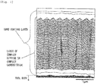
- a layer of a complex nitride or complex carbonitride of Ti and Al included in the hard coating layers of the present invention coated tools 1 to 15 a plurality of visual fields were observed using a scanning electron microscope (at a magnification of 5000x and 20,000x). As illustrated in a film configuration schematic view in Fig. 1 , it was confirmed that fine crystal grains having a hexagonal structure were present in crystal grain boundaries of a columnar structure constituted by the crystal grains having an NaCl type face-centered cubic structure, the area proportion thereof was 30 or less by area, and the average grain size R of the fine crystal grains was 0.01 ⁇ m to 0.3 ⁇ m.
- the average grain size R of the fine crystal grains could be obtained by searching a plurality of observation visual fields for three portions having a grain boundary length of 0.5 ⁇ m or greater among the grain boundaries of the columnar structure where the fine crystal grains were found, counting the number of grain boundaries that were present on a line segment 0.5 ⁇ m in each of the portions, and dividing 1.5 ⁇ m by the sum of the numbers of grain boundaries in the three portions.
- coated tools 1 to 9 hard coating layers including at least a layer of a complex nitride or complex carbonitride of Ti and Al were deposited on the surfaces of the tool bodies A to D to have a target layer thickness ( ⁇ m) shown in Fig. 8 under the conditions shown in Tables 3 and 5.
- comparative coated tools 1 to 9 were produced by forming the hard coating layers so that the position of the reaction gas on the surface of the tool body was not changed over time during a process of forming a (Ti 1-x Al x )(C y N 1-y ) layer.
- any of a lower layer and an upper layer shown in Table 6 was formed on the comparative coated tools 3 to 9 under the forming conditions shown in Table 3.
- a reference coated tool 10 shown in Table 8 was produced by depositing (Ti 1-x Al x )(C y N 1-y ) layers of a reference example on the surfaces of the tool body B and the tool body C to have target layer thicknesses through arc ion plating using a physical vapor deposition apparatus in the related art.
- conditions of the arc ion plating using the deposition of the reference example are as follows.
- the section of each of constituent layers of the present invention coated tools 1 to 9, the comparative coated tools 1 to 9, and the reference coated tool 10 was measured using a scanning electron microscope (at a magnification of 5000x). An average layer thickness was obtained by measuring and averaging the layer thicknesses of five points in an observation visual field. All of the results showed substantially the same average layer thicknesses as the target layer thicknesses shown in Tables 6 to 8.
- the average amount Xavg of Al of the layer of a complex nitride or complex carbonitride a sample of which the surface was polished using an electron probe micro-analyzer (EPMA) was irradiated with electron beams from the sample surface side, and the average amount Xavg of Al was obtained by averaging 10 points of the analytic result of obtained characteristic X-rays.
- the average amount Yavg of C was obtained by secondary ion mass spectrometry (SIMS). Ion beams were emitted toward a range of 70 ⁇ m ⁇ 70 ⁇ m from the sample surface side, and the concentration of components emitted by a sputtering action was measured in a depth direction.
- the average amount Yavg of C represents the average value in the depth direction of the layer of a complex nitride or complex carbonitride of Ti and Al.
- the amount of C excludes an unavoidable amount of C which is included even though gas containing C is not intentionally used as a gas raw material.
- the amount (atomic ratio) of the component C contained in the layer of a complex nitride or complex carbonitride in a case where the amount of supplied Al(CH 3 ) 3 was set to 0 was obtained as the unavoidable amount of C, and a value obtained by subtracting the unavoidable amount of C from the amount (atomic ratio) of the component C contained in the layer of a complex nitride or complex carbonitride obtained in a case where Al(CH 3 ) 3 was intentionally supplied was selected to be Yavg.
- an inclination angle frequency distribution of the hard coating layer in a state where the section of the hard coating layer including the layer of a complex nitride or complex carbonitride of Ti and Al in the direction perpendicular to the surface of the tool body was polished as a polished surface, the polished surface was set in the body tube of a field emission scanning electron microscope, and an electron beam was emitted toward each of the crystal grains having a cubic crystal lattice, which were present in a measurement range of the section polished surface at an incident angle of 70 degrees with respect to the section polished surface at an acceleration voltage of 15 kV and an emission current of 1 nA.
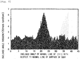
- Fig. 4 shows an inclined angle frequency distribution measured for the present invention coated tools
- Fig. 5 shows an inclined angle frequency distribution graph measured for the comparative coated tools.
- the polished surface was set in the body tube of the field emission scanning electron microscope, and an electron beam was emitted toward each of the crystal grains which were present in the measurement range of the section polished surface at an incident angle of 70 degrees with respect to the section polished surface at an acceleration voltage of 15 kV and an emission current of 1 nA.
- an electron backscatter diffraction image was measured using an electron backscatter diffraction apparatus device at an interval of 0.01 ⁇ m/step.
- Type Mixing composition (mass%) Co TiC TaC NbC Cr 3 C 2 WC Tool body A 8.0 1.5 - 3.0 0.4 Remainder B 8.5 - 1.8 0.2 - Remainder C 7.0 - - - - Remainder
- Type Mixing composition (mass%) Co Ni ZrC NbC Mo2C WC TiCN Tool body D 8 5 1 6 6 10 Remainder
- Constituent layers of hard coating layer Forming conditions pressure of reaction atmosphere is expressed as kPa and temperature is expressed as °C
- Type Formation symbol Reaction gas composition (% by volume) Reaction atmosphere Pressure Temperature (Ti 1-x Al x )(C y N 1-y ) layer TiAlCN TiAlCN See Tables 4 and 5 Ti compound layer TiC TiC TiCl 4 :4.0%, CH 4 :7.5%, H 2 :remainder 7 1000 TiN TiN TiCl 4 :4.0%, N 2 :
- Type Tool body symbol Hard coating layer (numerical value at the bottom indicates target average layer thickness ( ⁇ m)) Lower layer Upper layer First layer Second layer First layer Second layer First layer Second layer 1 A - - - - 2 D - - - - Present invention coated tool, comparative coated tool, reference coated tool 3 B TiN (0.3) - - - 4 C TiN (0.3) - - - 5 A TiN (0.3) - - - 6 D TiN (0.3) - Al 2 O 3 (2) - 7 B TiN (0.3) - TiCNO (0.3) Al 2 O 3 (1.5) 8 C TiC (0.5) - - 9 A TiN (0.3) TiCN (2) - - [Table 7] Type Tool body symbol Hard coating layer Layer of complex n
- the present invention coated tools 1 to 9, the comparative coated tools 1 to 9, and the reference coated tool 10 were subjected to dry high-speed face milling, which is a type of alloy steel high-speed intermittent cutting, and a center-cut cutting test, which are described below, and the flank wear width of a cutting edge was measured.
- dry high-speed face milling which is a type of alloy steel high-speed intermittent cutting
- center-cut cutting test which are described below
- a WC powder, a TiC powder, a ZrC powder, a TaC powder, an NbC powder, a Cr 3 C 2 powder, a TiN powder, and a Co powder were prepared, and the raw material powders were mixed in mixing compositions shown in Table 10. Wax was further added thereto, and the mixture was blended in acetone by a ball mill for 24 hours and was decompressed and dried.
- the resultant was press-formed into compacts having predetermined shapes at a pressure of 98 MPa, and the compacts were sintered in a vacuum at 5 Pa under the condition that the compacts were held at a predetermined temperature in a range of 1370°C to 1470°C for one hour.
- a cutting edge portion was subjected to honing to have a radius R of 0.07 mm, thereby forming tool bodies ⁇ to ⁇ made of WC-based cemented carbide with insert shapes according to ISO standard CNMG120412.
- a TiCN (TiC/TiN 50/50 in terms of mass ratio) powder, an NbC powder, a WC powder, a Co powder, and an Ni powder, all of which had an average grain size of 0.5 ⁇ m to 2 ⁇ m, were prepared, and the raw material powders were mixed in mixing compositions shown in Table 11, were subjected to wet mixing by a ball mill for 24 hours, and were dried. Thereafter, the resultant was press-formed into compacts at a pressure of 98 MPa, and the compacts were sintered in a nitrogen atmosphere at 1.3 kPa under the condition that the compacts were held at a temperature of 1500°C for one hour.
- a cutting edge portion was subjected to honing to have a radius R of 0.09 mm, thereby forming a tool body ⁇ made of TiCN-based cermet with an insert shape according to ISO standard CNMG120412.
- present invention coated tools 11 to 19 shown in Table 13 were produced by depositing hard coating layers including at least a (Ti 1-x Al x ) (C y N 1-y ) layer on the surfaces of the tool bodies ⁇ to ⁇ and the tool body ⁇ to have target layer thicknesses using a chemical vapor deposition apparatus under the conditions shown in Tables 3 and 4 in the same method as that in Example 1.
- any of a lower layer and an upper layer shown in Table 12 was formed on the present invention coated tools 13 to 19 under the forming conditions shown in Table 3.
- comparative coated tools 16 to 28 shown in Table 14 were produced by depositing hard coating layers on the surfaces of the same tool bodies ⁇ to ⁇ and the tool body ⁇ to have target layer thicknesses shown in Fig. 13 under the conditions shown in Tables 3 and 5 using a typical chemical vapor deposition apparatus.
- coated tools 11 to 19 any of a lower layer and an upper layer shown in Table 12 was formed on the comparative coated tools 11 to 19 under the forming conditions shown in Table 3.
- a reference coated tool 20 shown in Table 14 was produced by depositing (Ti 1-x Al x ) (C y N 1-y ) layers of the reference example on the surfaces of the tool body ⁇ and the tool body ⁇ to have target layer thicknesses through arc ion plating using a physical vapor deposition apparatus in the related art.
- Example 2 The same conditions as those described in Example 1 were used as the conditions of the arc ion plating.
- the section of each of constituent layers of the present invention coated tools 11 to 19, the comparative coated tools 11 to 19, and the reference coated tool 20 was measured using a scanning electron microscope (at a magnification of 5000x). An average layer thickness was obtained by measuring and averaging the layer thicknesses of five points in an observation visual field. All of the results showed substantially the same average layer thicknesses as the target layer thicknesses shown in Tables 12 to 14.
- the average amount Xavg of Al, the average amount Yavg of C, the average grain width W and the average aspect ratio A of crystal grains having a cubic structure included in the (Ti 1-x Al x ) (C y N 1-y ) layer of a columnar structure were calculated.
- inclined angles of normal lines of ⁇ 111 ⁇ planes which were crystal planes of the crystal grains having an NaCl type face-centered cubic structure with respect to the normal line (the direction perpendicular to the surface of the body in the section polished surface) of the surface of the body were measured.
- measured inclined angles in a range of 0 degrees to 45 degrees among the measured inclined angles were divided into intervals of 0.25 degrees, frequencies in the respective divisions were aggregated, and the presence of the peaks of the frequencies present in a range of 0 degrees to 10 degrees was checked. In addition, the proportion of the frequencies present in the range of 0 degrees to 10 degrees was obtained.
- the average grain size R of fine crystal grains that were present in the grain boundaries of the columnar structure constituted by the individual crystal grains having an NaCl type face-centered cubic structure and the area proportion of the fine crystal grains were calculated using the same method as that described in Example 1.
- a layer of a complex nitride or complex carbonitride of Ti and Al included in the hard coating layers of the present invention coated tools 11 to 19 a plurality of visual fields were observed using a scanning electron microscope (at a magnification of 5000x and 20,000x).
- a scanning electron microscope at a magnification of 5000x and 20,000x.
- a (Ti 1-x Al x ) (C y N 1-y ) layer of a columnar structure in which NaCl type face-centered cubic crystals and hexagonal crystals were present was confirmed.
- the columnar structure constituted by the individual crystal grains having a cubic structure were analyzed in the longitudinal sectional direction of the layer of a complex nitride or complex carbonitride of Ti and Al using an electron backscatter diffraction apparatus, and it was confirmed that the fine crystal grains present in the grain boundaries had a hexagonal structure.
- Type Mixing composition (mass%) Co TiC ZrC TaC NbC Cr 3 C 2 TiN WC Tool body ⁇ 6.5 - 1.5 - 2.9 0.1 1.5 Remainder ⁇ 7.6 2.6 - 4.0 0.5 - 1.1 Remainder ⁇ 6.0 - - - - - - Remainder
- Type Mixing composition (mass%) Co Ni NbC WC TiCN Tool body ⁇ 11 4 6 15 Remainder
- Type Tool body symbol Hard coating layer (numerical value at the bottom indicates target average layer thickness ( ⁇ m)) Lower layer Upper layer First layer Second layer First layer First layer First layer First layer Second layer 11 a - - - - 12 ⁇ - - - - 13 ⁇ TiN (0.3) - - - Present invention coated tool, comparative coated tool, reference coated tool 14 ⁇ TiN (0.3) - - - 15 ⁇ TiN (0.3) - - - 16 ⁇ TiN (0.3) - Al 2 O 3 (2.5)
- the present invention coated tools 11 to 19, the comparative coated tools 11 to 19, and the reference coated tool 20 were subjected to a dry high-speed intermittent cutting test for carbon steel and a wet high-speed intermittent cutting test for cast iron, which are described below, and the flank wear width of a cutting edge was measured.
- a cBN powder, a TiN powder, a TiCN powder, a TiC powder, an Al powder, and an Al 2 O 3 powder were prepared, and the raw material powders were mixed in mixing compositions shown in Table 16.
- the mixture was wet-blended by a ball mill for 80 hours and was dried.
- the resultant was press-formed into compacts having dimensions with a diameter of 50 mm and a thickness of 1.5 mm at a pressure of 120 MPa, and the compacts were then sintered in a vacuum at a pressure of 1 Pa under the condition that the compacts were held at a predetermined temperature in a range of 900°C to 1300°C for 60 minutes, thereby producing cutting edge preliminary sintered bodies.
- the resultant was loaded in a typical ultrahigh-pressure sintering apparatus, and was subjected to ultrahigh-pressure sintering under typical conditions including a pressure of 4 GPa, a predetermined temperature in a range of 1200°C to 1400°C, and a holding time of 0.8 hours. After the sintering, upper and lower surfaces were polished using a diamond grinding wheel, and were split into predetermined dimensions by a wire electric discharge machining apparatus.
- the resultant was brazed to a brazing portion (corner portion) of an insert body made of WC-based cemented carbide having a composition including Co: 5 mass%, TaC: 5 mass%, and WC: the remainder and a shape (a 80° rhombic shape with a thickness of 4.76 mm and an inscribed circle diameter of 12.7 mm) according to ISO standard CNGA120412 using a brazing filler metal made of a Ti-Zr-Cu alloy having a composition including Zr: 37.5%, Cu: 25%, and Ti: the remainder in terms of mass%, and the outer circumference thereof was machined into predetermined dimensions.
- present invention coated tools 21 to 24 shown in Table 18 were produced by depositing hard coating layers including at least a (Ti 1-x Al x ) (C y N 1-y ) layer on the surfaces of the tool bodies a and b to have target layer thicknesses using a typical chemical vapor deposition apparatus under the conditions shown in Tables 3 and 4 in the same method as that in Example 1.
- any of a lower layer and an upper layer shown in Table 17 was formed on the present invention coated tools 22 to 24 under the forming conditions shown in Table 3.
- comparative coated tools 21 to 24 shown in Table 19 were produced by depositing hard coating layers including at least a (Ti 1-x Al x ) (C y N 1-y ) layer on the surfaces of the same tool bodies a and b to have target layer thicknesses under the conditions shown in Tables 3 and 5 using a typical chemical vapor deposition apparatus.
- coated tools 22 to 24 any of a lower layer and an upper layer shown in Table 17 was formed on the comparative coated tools 22 to 24 under the forming conditions shown in Table 3.
- a reference coated tool 25 shown in Table 19 was produced by depositing (Ti 1-x Al x ) (C y N 1-y ) layers on the surfaces of the tool bodies a and b to have target layer thicknesses through arc ion plating using a physical vapor deposition apparatus in the related art.
- Example 2 The same conditions as those described in Example 1 were used as the conditions of the arc ion plating, and the reference coated tool 25 was produced by depositing (Al,Ti)N layers having a target composition and a target layer thickness shown in Table 19 on the surfaces of the tool bodies.
- the section of each of constituent layers of the present invention coated tools 21 to 24, the comparative coated tools 21 to 24, and the reference coated tool 25 was measured using a scanning electron microscope (at a magnification of 5000x). An average layer thickness was obtained by measuring and averaging the layer thicknesses of five points in an observation visual field. All of the results showed substantially the same average layer thicknesses as the target layer thicknesses shown in Tables 17 to 19.
- the average amount Xavg of Al, the average amount Yavg of C, the average grain width W and the average aspect ratio A of crystal grains having an NaCl type face-centered cubic structure included in the (Ti 1-x Al x ) (C y N 1-y ) layer were calculated.
- inclined angles of normal lines of ⁇ 111 ⁇ planes which were crystal planes of the crystal grains having an NaCl type face-centered cubic structure with respect to the normal line (the direction perpendicular to the surface of the body in the section polished surface) of the surface of the body were measured.
- measured inclined angles in a range of 0 degrees to 45 degrees among the measured inclined angles were divided into intervals of 0.25 degrees, frequencies in the respective divisions were aggregated, and the presence of the peaks of the frequencies present in a range of 0 degrees to 10 degrees was checked. In addition, the proportion of the frequencies present in the range of 0 degrees to 10 degrees was obtained.
- the average grain size R of fine crystal grains that were present in the grain boundaries of the columnar structure constituted by the individual crystal grains having an NaCl type face-centered cubic structure and the area proportion of the fine crystal grains were calculated using the same method as that described in Example 1. The results are shown in Tables 18 and 19.
- Type Tool body symbol Hard coating layer (numerical value at the bottom indicates target average layer thickness ( ⁇ m)) Lower layer Upper layer First layer Present invention coated tool, comparative coated tool, reference coated tool 31 a - - 32 b TiN (0.3) - 33 a TiN (0.3) - 34 b TiN (0.3) TiN (0.3) [Table 18] Type Tool body symbol Hard coating layer Layer of complex nitride or complex carbonitride of Ti and Al (Ti 1-x Al x )(C y N 1-y ) Formation symbol of TiAlCN film forming process (see Table 4) Average amount Xavg of Al Average amount Yavg of C Difference Dx between average of maximum values of x and an average of minimum values Division of inclined angles in which highest peak is present in inclined angle frequency distribution (degrees) Proportion of frequencies of 0 degrees to 10 degrees in inclined angle division in inclined angle frequency distribution (%) Average grain width W of cubic grains (mm) Average aspect ratio A of cubic grains Average value of periods of compositional change in Ti and Al
- the present invention coated tools 21 to 24, the comparative coated tools 21 to 24, and the reference coated tool 25 were subjected to a dry high-speed intermittent cutting test for carburized alloy steel, which is described below, and the flank wear width of a cutting edge was measured.
- Table 20 The results of the cutting test are shown in Table 20.
- Table 20 Type Flank wear width (mm)
- Present invention coated tool 21 0.18 Comparative coated tool 21 1.5 22 0.16 22 1.2 23 0.12 23 2.2 24 0.15 24 2.8
- Reference coated tool 25 1.3 Mark * in boxes of comparative coated tools and reference coated tools indicates a cutting time (min) until the end of a service life caused by the occurrence of chipping.
- the coated tool of the present invention exhibits excellent wear resistance as well as excellent chipping resistance and defect resistance during long-term use even in a case of being used for high-speed intermittent cutting work during which intermittent and impact loads are exerted on a cutting edge.
- the comparative coated tools 1 to 9, 10 to 19, 21 to 24, and the reference coated tools 10, 20, and 25 generates high-temperature heat and generates chipping, defects, and the like in a case of being used for high-speed intermittent cutting work during which intermittent and impact loads are exerted on a cutting edge, resulting in the end of the service life within a short period of time.
- the coated tool of the present invention can be used as a coated tool for various work materials as well as for high-speed intermittent cutting work of alloy steel and further exhibits excellent chipping resistance and wear resistance during long-term use, thereby sufficiently satisfying an improvement in performance of a cutting device, power saving and energy saving during cutting work, and a further reduction in costs.
Abstract

Description
- The present invention relates to a surface-coated cutting tool (hereinafter, referred to as coated tool), in which a hard coating layer exhibits excellent chipping resistance during high-speed intermittent cutting work of alloy steel or the like during which high-temperature heat is generated and an impact load is exerted on a cutting edge, and excellent cutting performance is exhibited during long-term use.
- Hitherto, in general, coated tools in which the surfaces of tool bodies made of tungsten carbide (hereinafter, referred to as WC)-based cemented carbide, titanium carbonitride (hereinafter, referred to as TiCN)-based cermet, or a cubic boron nitride (hereinafter, referred to as cBN)-based ultrahigh-pressure sintered body (hereinafter, collectively referred to as a tool body) are covered with a Ti-Al-based complex nitride layer as a hard coating layer through a physical vapor deposition method are known, and it is known that these coated tools exhibit excellent wear resistance.
- However, although the coated tool coated with the Ti-Al-based complex nitride layer in the related art has relatively excellent wear resistance, in a case of using the coated tool under high-speed intermittent cutting conditions, abnormal wear such as chipping easily occurs. Therefore, various suggestions for an improvement in the hard coating layer have been made.
- For example,
PTL 1 discloses that a coating which is excellent in wear resistance, seizure resistance, and oxidation resistance, has a low coefficient of friction, and has good sliding characteristics is obtained by forming a complex hard coating made of at least two types of metal nitride among nitrides of Cr, Ti, Al, and V on the surface of a tool body and causing the strength ratio I(111) / 1(200) between the strengths I(111) and 1(200) of the X-ray diffraction peaks of a (111) plane and a (200) plane obtained through X-ray diffraction of the hard coating to be a value of 3 to 6. - For example,
PTL 2 describes that by performing chemical vapor deposition in a mixed reaction gas of TiCl4, AlCl3, and NH3 in a temperature range of 650°C to 900°C, a (Ti1-xAlx) N layer in which the value of the amount x of Al is 0.65 to 0.95 can be deposited. However, this literature is aimed at further coating the (Ti1-xAlx) N layer with an Al2O3 layer and thus improving a heat insulation effect. Therefore, the effects of the formation of the (Ti1-xAlx) N layer in which the value of the amount x of Al is increased to 0.65 to 0.95 on cutting performance is not clear. - In addition, for example, PTL 3 suggests that the heat resistance and fatigue strength of a coated tool are improved by coating a TiCN layer and an Al2O3 layer as inner layers with a (Ti1-xAlx)N layer (x is 0.65 to 0.90 in terms of atomic ratio) having a cubic structure or a cubic structure including a hexagonal structure as an outer layer, and applying a compressive stress of 100 MPa to 1100 MPa to the outer layer.
-
- [PTL 1]
JP-A-2000-144376 - [PTL 2]
JP-T-2011-516722 - [PTL 3]
JP-T-2011-513594 - There has been a strong demand for power saving and energy saving during cutting work in recent years. In accordance with this, there is a trend toward a further increase in speed and efficiency during cutting work. Therefore, abnormal damage resistance such as chipping resistance, defect resistance, and peeling resistance is further required for a coated tool, and excellent wear resistance is required during long-term use.
- However, in a coated tool described in
PTL 1, since the hard coating is deposited through the physical vapor deposition method, for example, it is difficult to increase the amount of Al in the hard coating. Therefore, in a case where the coated tool is provided for high-speed intermittent cutting work of alloy steel or the like, there is a problem in that it cannot be said that wear resistance and chipping resistance are sufficient. - On the other hand, in the (Ti1-xAlx)N layer deposited through the chemical vapor deposition method described in
PTL 2, the amount x of Al can be increased. In addition, since a cubic structure can be formed, a hard coating layer having a predetermined hardness and excellent wear resistance is obtained. However, there are problems in that the adhesive strength thereof to a tool body is insufficient and the toughness thereof may be deteriorated. - Furthermore, in the coated tool described in PTL 3, although the coated tool has a predetermined hardness and excellent wear resistance, the toughness thereof is deteriorated. Therefore, in a case where the coated tool is provided for high-speed intermittent cutting work of alloy steel or the like, there are problems in that abnormal damage such as chipping, defects, and peeling easily occurs and it cannot be said that satisfactory cutting performance is exhibited.
- Here, a technical problem to be solved by the present invention, that is, an object of the present invention is to provide a coated tool which has excellent toughness and exhibits excellent chipping resistance and wear resistance during long-term use even in a case of being provided for high-speed intermittent cutting work of alloy steel or the like.
- Therefore, from the above-described viewpoints, the inventors intensively studied to improve the chipping resistance and wear resistance of a coated tool in which a hard coating layer containing at least a complex nitride or complex carbonitride of Ti and Al (hereinafter, sometimes referred to as "(Ti,Al)(C,N)" or "(Ti1-xAlx)(CyN1-y)") is deposited through chemical vapor deposition. As a result, the following knowledge was obtained.
- That is, in the related art, in a hard coating layer which includes at least one (Ti1-xAlx)(CyN1-y) layer and has a predetermined average layer thickness, in a case where the (Ti1-xAlx)(CyN1-y) layer is formed in a columnar shape in a direction perpendicular to a tool body, the hard coating layer has high wear resistance. On the other hand, as the anisotropy of the (Ti1-xAlx)(CyN1-y) layer increases, the toughness of the (Ti1-xAlx)(CyN1-y) layer decreases. As a result, the chipping resistance and defect resistance thereof decrease, and sufficient wear resistance is not exhibited during long-term use. In addition, it cannot be said that the service life of the tool is satisfactory.
- The inventors intensively studied a (Ti1-xAlx)(CyN1-y) layer included in a hard coating layer, and on the basis of a completely novel idea that a periodic compositional variation in Ti and Al in crystal grains having an NaCl type face-centered cubic structure in the (Ti1-xAlx)(CyN1-y) layer is formed, obtained novel knowledge that an increase in both hardness and toughness is achieved by introducing strain into the crystal grains having an NaCl type face-centered cubic structure, and as a result, the chipping resistance and wear resistance of the hard coating layer can be improved.
- Specifically, it was found that the hard coating layer includes at least a layer of a complex nitride or complex carbonitride of Ti and Al, which is formed by a chemical vapor deposition method, in a case where the layer is expressed by the composition formula: (Ti1-xAlx)(CyN1-y), the average amount Xavg of Al in the total amount of Ti and Al and the average amount Yavg of C in the total amount of C and N (both Xavg and Yavg are atomic ratios) respectively satisfy 0.60 ≤ Xavg ≤ 0.95 and 0 ≤ Yavg ≤ 0.005, the layer of a complex nitride or complex carbonitride includes at least a phase of a complex nitride or complex carbonitride having an NaCl type face-centered cubic structure, regarding the layer, in a case where the layer is analyzed in a longitudinal sectional direction of the layer using an electron backscatter diffraction apparatus, when an inclined angle frequency distribution is obtained by measuring inclined angles of normal lines of {111} planes which are crystal planes of the crystal grains with respect to a normal direction of the surface of the tool body, dividing inclined angles in a range of 0 degrees to 45 degrees with respect to the normal direction among the measured inclined angles into intervals of 0.25 degrees, and aggregating frequencies in the respective divisions, a highest peak is present in an inclined angle division in a range of 0 degrees to 10 degrees and the sum of frequencies that are present in the range of 0 degrees to 10 degrees has a proportion of 45% or higher of the total of the frequencies in the inclined angle frequency distribution, regarding the layer of a complex nitride or complex carbonitride, in a case where the layer is observed in the longitudinal sectional direction, a columnar structure in which the average grain width W of the individual crystal grains having an NaCl type face-centered cubic structure in the layer of a complex nitride or complex carbonitride is 0.1 µm to 2.0 µm and the average aspect ratio A thereof is 2 to 10 is included, and in the individual crystal grains having an NaCl type face-centered cubic structure, a periodic compositional variation in Ti and Al in the composition formula: (Ti1-xAlx)(CyN1-y) is present along the normal direction of the surface of the tool body in the layer of a complex nitride or complex carbonitride and the difference Δx between the average of maximum values of x which varies periodically and the average of minimum values thereof is 0.03 to 0.25, whereby strain is introduced into the crystal grains having an NaCl type face-centered cubic structure, the hardness and toughness of the (Ti1-xAlx)(CyN1-y) layer are increased compared to a hard coating layer in the related art, and chipping resistance and defect resistance are correspondingly improved, and excellent wear resistance is exhibited during long-term use.
- In addition, the (Ti1-xAlx)(CyN1-y) layer having the configuration described above can be formed by, for example, the following chemical vapor deposition method in which the composition of a reaction gas varies periodically on the surface of the tool body.
- In a chemical vapor deposition reaction apparatus which is used, a gas group A of NH3, N2, and H2 and a gas group B of TiCl4, Al(CH3)3, AlCl3, NH3, N2, and H2 are supplied into the reaction apparatus from separate gas supply tubes, the supplying of the gas group A and the gas group B into the reaction apparatus is performed so that the gases are allowed to flow at time intervals of a predetermined period only for a shorter time than the period, the supplying of the gases of the gas group A and the gas group B has a phase difference of a time shorter than the time for which the gases are supplied, and the composition of the reaction gas on the surface of the tool body can be changed over time between (a) the gas group A, (b) a mixed gas of the gas group A and the gas group B, and (c) the gas group B. Moreover, in the present invention, there is no need to introduce a long-term exhaust process intended for strict gas substitution. Therefore, as a gas supply method, for example, it is possible to realize the composition of the reaction gas on the surface of the tool body being able to be changed over time between (a) a mixed gas primarily containing the gas group A, (b) a mixed gas of the gas group A and the gas group B, and (c) a mixed gas primarily containing the gas group B by rotating gas supply ports, rotating the tool body, or reciprocating the tool body while continuously supplying the gases over time.
- The (Ti1-xAlx)(CyN1-y) layer having a predetermined target layer thickness is formed on the surface of the tool body by performing a thermal CVD method for a predetermined time, for example, using, as the composition of the reaction gas (% by volume with respect to the total amount of the gas group A and the gas group B), the gas group A of NH3: 1.0% to 2.0%, N2: 0% to 5%, and H2: 55% to 60% and the gas group B of AlCl3: 0.6% to 0.9%, TiCl4: 0.2% to 0.3%, Al(CH3)3: 0% to 0.5%, N2: 0.0% to 12.0%, and H2: the remainder, under a reaction atmosphere pressure of 4.5 kPa to 5.0 kPa, at a reaction atmosphere temperature of 700°C to 900°C, and with a supply period of 1 second to 5 seconds, a gas supply time of 0.15 seconds to 0.25 seconds per one period, and a phase difference between gas supply A and gas supply B of 0.10 seconds to 0.20 seconds.
- As described above, the gas group A and the gas group B are supplied so that the times at which the gas group A and the gas group B arrive at the surface of the tool body are different from each other, a nitrogen raw material gas in the gas group A is set to NH3: 1.0% to 2.0% and N2: 0% to 5%, and a metal chloride raw material or a carbon raw material in the gas group B is set to AlCl3: 0.6% to 0.9%, TiCl4: 0.2% to 0.3%, or Al(CH3)3: 0% to 0.5%. Therefore, local compositional unevenness, dislocations, and point defects are introduced into crystal grains, and thus local strain in a crystal lattice is formed. Furthermore, the degree of {111} orientation on the side of the surface of the tool body and on the side of the surface of a coating in the crystal grains can be changed. As a result, it was found that toughness is dramatically improved while wear resistance is maintained. As a result, particularly defect resistance and chipping resistance are improved. Therefore, it was found that even in a case where the tool body is used for high-speed intermittent cutting work of alloy steel or the like during which intermittent and impact loads is exerted on a cutting edge, the hard coating layer can exhibit excellent cutting performance during long-term use.
- The present invention is made based on the above-described knowledge and is characterized by including
- "(1) a surface-coated cutting tool in which a hard coating layer is provided on a surface of a tool body made of any of tungsten carbide-based cemented carbide, titanium carbonitride-based cermet, and a cubic boron nitride-based ultrahigh-pressure sintered body, in which
- (a) the hard coating layer includes at least a layer of a complex nitride or complex carbonitride of Ti and Al, the layer being formed to an average layer thickness of 1 µm to 20 µm in a chemical vapor deposition method, and in a case where the layer is expressed by the composition formula: (Ti1-xAlx)(CyN1-y), an average amount Xavg of Al of the layer of a complex nitride or complex carbonitride in a total amount of Ti and Al and an average amount Yavg of C in a total amount of C and N (both Xavg and Yavg are atomic ratios) respectively satisfy 0.60 ≤ Xavg ≤ 0.95 and 0 ≤ Yavg ≤ 0.005,
- (b) the layer of a complex nitride or complex carbonitride includes at least a phase of a complex nitride or complex carbonitride having an NaCl type face-centered cubic structure,
- (c) regarding the layer of a complex nitride or complex carbonitride, in a case where crystal orientations of individual crystal grains having an NaCl type face-centered cubic structure in the layer of a complex nitride or complex carbonitride in a longitudinal sectional direction of the layer of a complex nitride or complex carbonitride are analyzed using an electron backscatter diffraction apparatus, when an inclined angle frequency distribution is obtained by measuring inclined angles of normal lines of {111} planes which are crystal planes of the crystal grains with respect to a normal direction of the surface of the tool body, dividing inclined angles in a range of 0 degrees to 45 degrees with respect to the normal direction among the measured inclined angles into intervals of 0.25 degrees, and aggregating frequencies in the respective divisions, a highest peak is present in an inclined angle division in a range of 0 degrees to 10 degrees, and a sum of frequencies that are present in the range of 0 degrees to 10 degrees has a proportion of 45% or higher of a total of the frequencies in the inclined angle frequency distribution,
- (d) regarding the layer of a complex nitride or complex carbonitride, in a case where the layer is observed in the longitudinal sectional direction, a columnar structure in which an average grain width W of the individual crystal grains having an NaCl type face-centered cubic structure in the layer of a complex nitride or complex carbonitride is 0.1 µm to 2.0 µm and an average aspect ratio A thereof is 2 to 10 is included, and
- (e) in the individual crystal grains having an NaCl type face-centered cubic structure in the layer of a complex nitride or complex carbonitride, a periodic compositional variation in Ti and Al in the (Ti1-xAlx)(CyN1-y) is present along one orientation among equivalent crystal orientations expressed by <001> of the crystal grains, and a difference Δx between an average of maximum values of x which varies periodically and an average of minimum values thereof is 0.03 to 0.25.
- (2) The surface-coated cutting tool described in (1), in which, in the crystal grains having an NaCl type face-centered cubic structure in which the periodic compositional variation in Ti and Al is present in the layer of a complex nitride or complex carbonitride, the periodic compositional variation in Ti and Al is present along one orientation among the equivalent crystal orientations expressed by <001> of the crystal grains, a period along the orientation is 3 nm to 100 nm, and a change in an amount XO of Al in a plane perpendicular to the orientation in a total amount of Ti and Al is 0.01 or less.
- (3) The surface-coated cutting tool described in (1) or (2), in which, regarding the layer of a complex nitride or complex carbonitride, lattice constants a of the crystal grains having an NaCl type face-centered cubic structure are obtained from X-ray diffraction, and the lattice constants a of the crystal grains having an NaCl type face-centered cubic structure satisfy a relationship of 0.05aTiN + 0.95aAlN ≤ a ≤ 0.4aTiN + 0.6aAlN for a lattice constant aTiN of cubic TiN and a lattice constant aAlN of cubic AlN.
- (4) The surface-coated cutting tool described in any one of (1) to (3), in which the layer of a complex nitride or complex carbonitride is formed of a single phase of a complex nitride or complex carbonitride of Ti and Al having an NaCl type face-centered cubic structure.
- (5) The surface-coated cutting tool described in any one of (1) to (3), in which, regarding the layer of a complex nitride or complex carbonitride, in a case where the layer is observed in the longitudinal sectional direction, in crystal grain boundaries of the columnar structure constituted by the individual crystal grains having an NaCl type face-centered cubic structure in the layer of a complex nitride or complex carbonitride, fine crystal grains having a hexagonal structure are present, an area proportion of the fine crystal grains present is 30% or lower by area, and an average grain size R of the fine crystal grains is 0.01 µm to 0.3 µm.
- (6) The surface-coated cutting tool described in any one of (1) to (5), in which, between the tool body and the layer of a complex nitride or complex carbonitride of Ti and Al, a lower layer which is formed of a Ti compound layer that includes one layer or two or more layers of a Ti carbide layer, a Ti nitride layer, a Ti carbonitride layer, a Ti oxycarbide layer, and a Ti oxycarbonitride layer and has an average total layer thickness of 0.1 µm to 20 µm is present.
- (7) The surface-coated cutting tool described in any one of (1) to (6), in which an upper layer which includes an aluminum oxide layer having an average layer thickness of at least 1 µm to 25 µm is present in an upper portion of the layer of a complex nitride or complex carbonitride.
- (8) The surface-coated cutting tool described in any one of (1) to (7), in which the layer of a complex nitride or complex carbonitride is formed by a chemical vapor deposition method in which at least trimethylaluminum is contained as a reaction gas component."
- The present invention will be described below in detail.
- The hard coating layer of the present invention includes at least the layer of a complex nitride or complex carbonitride of Ti and Al, which is formed through chemical vapor deposition and is expressed by the composition formula: (Ti1-xAlx)(CyN1-y). The layer of a complex nitride or complex carbonitride has high hardness and excellent wear resistance, and the effect thereof is significantly exhibited particularly when the average layer thickness thereof is 1 µm to 20 µm. The reason for this is that when the average layer thickness thereof is smaller than 1 µm, the layer thickness thereof is too small to sufficiently ensure wear resistance during long-term use, and when the average layer thickness thereof is greater than 20 µm, the crystal grains of the layer of a complex nitride or complex carbonitride of Ti and Al are likely to coarsen and chipping easily occurs. Therefore, the average layer thickness thereof was selected to be 1 µm to 20 µm.
- In addition, the layer of a complex nitride or complex carbonitride may have a mixed phase of cubic and hexagonal phases. However, when the area proportion of the crystal grains having an NaCl type face-centered cubic structure is lower than 70% by area, a reduction in hardness occurs. Therefore, it is preferable that the area proportion of the crystal grains having an NaCl type face-centered cubic structure is 70% by area and it is more preferable that the layer has a single phase of a complex nitride or complex carbonitride of Ti and Al with the NaCl type face-centered cubic structure.
- The layer of a complex nitride or complex carbonitride included in the hard coating layer of the present invention is controlled such that that the average amount Xavg of Al in the total amount of Ti and Al and the average amount Yavg of C in the total amount of C and N (both Xavg and Yavg are atomic ratios) respectively satisfy 0.60 ≤ Xavg ≤ 0.95 and 0 ≤ Yavg ≤ 0.005.
- The reason for this is that when the average amount Xavg of Al is less than 0.60, the hardness of the layer of a complex nitride or complex carbonitride of Ti and Al deteriorates. Therefore, in a case where the layer is provided for high-speed intermittent cutting work of alloy steel or the like, the wear resistance thereof is insufficient. On the other hand, when the average amount Xavg of Al is more than 0.95, the amount of Ti is relatively reduced, resulting in embrittlement and a reduction in chipping resistance. Therefore, the average amount Xavg of Al was selected to be 0.60 ≤ Xavg ≤ 0.95.
- When the average amount Yavg of the component C contained in the layer of a complex nitride or complex carbonitride is a small amount in a range of 0 ≤ Yavg ≤ 0.005, the adhesion between the layer of a complex nitride or complex carbonitride and the tool body or the lower layer is improved. In addition, the lubricity thereof is improved and thus an impact during cutting is relieved, resulting in an improvement in the defect resistance and chipping resistance of the layer of a complex nitride or complex carbonitride. On the other hand, when the average amount Yavg of the component C is outside of the range of 0 ≤ Yavg ≤ 0.005, the toughness of the layer of a complex nitride or complex carbonitride decreases and the defect resistance and chipping resistance in contrast, decrease, which is not preferable. Therefore, the average amount Yavg of C was selected to be 0 ≤ Yavg ≤ 0.005.
- Inclined Angle Frequency Distribution for {111} Planes Which Are Crystal Planes of Individual Crystal grains Having NaCl Type Face-Centered Cubic Structure in Layer of Complex Nitride or Complex Carbonitride of Ti and Al ((Ti1-xAlx)(CyN1-y)Layer) :
- Regarding the (Ti1-xAlx)(CyN1-y) layer of the present invention, in a case where the crystal orientations of individual crystal grains having an NaCl type face-centered cubic structure are analyzed in the longitudinal sectional direction thereof using an electron backscatter diffraction apparatus, the inclined angles of normal lines of {111} planes which are the crystal planes of the crystal grains with respect to the normal line of the surface of the tool body (a direction perpendicular to the surface of the tool body in a section polished surface) are measured. When inclined angles in a range of 0 degrees to 45 degrees with respect to the normal direction among the measured inclined angles are divided into intervals of 0.25 degrees and frequencies in the respective divisions are aggregated, in a case where a form of an inclined angle frequency distribution is shown in which a highest peak is present in an inclined angle division in a range of 0 degrees to 10 degrees and the sum of frequencies that are present in the range of 0 degrees to 10 degrees has a proportion of 45% or higher of the total of the frequencies in the inclined angle frequency distribution, the hard coating layer including the layer of a complex nitride or complex carbonitride of Ti and Al has high hardness while maintaining the NaCl type face-centered cubic structure. Furthermore, with the form of the inclined angle frequency distribution as described above, the adhesion between the hard coating layer and the body is dramatically improved.
- Therefore, even in a case where the coated tool is used, for example, for high-speed intermittent cutting of stainless steel or the like, the occurrence of chipping, defects, peeling, and the like is suppressed, and excellent wear resistance is exhibited.
- Regarding the crystal grains having an NaCl type face-centered cubic structure in the layer of a complex nitride or complex carbonitride, in a case where the grain width thereof in a direction parallel to the surface of the tool body is referred to as w, and the grain length thereof in the direction perpendicular to the surface of the tool body is referred to as 1, the ratio l/w between w and 1 is referred to as the aspect ratio a of each crystal grain, the average value of the aspect ratios a obtained for the individual crystal grains is further referred to as an average aspect ratio A, and the average value of the grain widths w obtained for the individual crystal grains is referred to as an average grain width W, in the present invention, the average grain width W and the average aspect ratio A are controlled to be 0.1 µm to 2.0 µm and 2 to 10, respectively.
- When this condition is satisfied, the crystal grains having an NaCl type face-centered cubic structure included in the layer of a complex nitride or complex carbonitride have a columnar structure and exhibit excellent wear resistance. On the other hand, when the average aspect ratio A is lower than 2, a periodic compositional distribution, which is a feature of the present invention, is less likely to be formed in the crystal grains having an NaCl type face-centered cubic structure. When the average aspect ratio A is higher than 10, it is difficult to suppress the propagation of cracks. In addition, when the average grain width W is smaller than 0.1 µm, wear resistance decreases. When the average grain width W is greater than 2.0 µm, toughness decreases. Therefore, the average grain width W of the crystal grains having an NaCl type face-centered cubic structure included in the layer of a complex nitride or complex carbonitride was selected to be 0.1 µm to 2.0 µm.
- Furthermore, in a case where crystals having an NaCl type face-centered cubic structure are expressed by the composition formula: (Ti1-xAlx)(CyN1-y), when a periodic compositional variation in Ti and Al is present in crystal grains, strain occurs in the crystal grains, resulting in an improvement in hardness. However, when the difference Δx between the average of maximum values of x and the average of minimum values thereof in the composition formula, which is an index of the degree of the compositional variation in Ti and Al, is smaller than 0.03, the degree of strain in the crystal grains described above is low, and a sufficient improvement in hardness cannot be expected. On the other hand, when the difference Δx between the average of the maximum values of x and the average of the minimum values thereof is greater than 0.25, the degree of strain in the crystal grains becomes too high, there are more lattice defects, and hardness decreases. Here, regarding the compositional variation in Ti and Al present in the crystal grains having an NaCl type face-centered cubic structure, the difference Δx between the average of the maximum values of x which varies periodically and the average of the minimum values thereof selected to be 0.05 to 0.25.
- In addition, it is preferable that a periodic compositional variation in Ti and Al is present along one orientation among equivalent crystal orientations expressed by <001> of the crystal grains having an NaCl type face-centered cubic structure. However, when the period thereof is smaller than 3 nm, toughness decreases. On the other hand, when the period is greater than 100 nm, the effect of improving hardness cannot be expected. Therefore, it is preferable that the period that is present along one orientation among equivalent crystal orientations expressed by <001> of cubic crystal grains is 3 nm to 100 nm. In addition, when a change in the amount XO of Al in the total amount of Ti and Al in a plane orthogonal to the orientation is 0.01 or lower, dislocation slip in a {001} plane at an angle with respect to the {111} plane is induced, resulting in an improvement in toughness.
- An X-ray diffraction test was performed on the layer of a complex nitride or complex carbonitride using an X-ray diffraction apparatus and Cu-Kα radiation as a radiation source and the lattice constants a of the crystal grains having an NaCl type face-centered cubic structure were obtained. When the lattice constants a of the crystal grains satisfy a relationship of 0.05aTiN + 0.95aAlN ≤ a ≤ 0.4aTiN + 0.6aAlN for the lattice constant aTiN: 4.24173 A of cubic TiN (JCPDS 00-038-1420) and the lattice constant aAlN: 4.045 A of cubic AlN (JCPDS 00-046-1200), higher hardness is exhibited, and high thermal conductivity is exhibited. Therefore, in addition to excellent wear resistance, excellent thermal shock resistance is provided.
- Since fine crystal grains having a hexagonal structure are present in grain boundaries of a columnar structure constituted by the individual crystal grains having an NaCl type face-centered cubic structure, grain boundary sliding is suppressed, resulting in an improvement in toughness. However, when the area proportion thereof is higher than 30% by area, the proportion of crystal phases having an NaCl type face-centered cubic structure is relatively decreased and thus hardness decreases, which is not preferable. In addition, when the average grain size R of the fine crystal grains is smaller than 0.01 µm, an effect of suppressing grain boundary sliding is insufficient. When the average grain size R thereof is greater than 0.3 µm, strain in the columnar structure increases and thus hardness decreases, which is not preferable.
- The layer of a complex nitride or complex carbonitride of the present invention exhibits sufficient effects in itself. However, in a case where the lower layer which is formed of a Ti compound layer that includes one layer or two or more layers of a Ti carbide layer, a Ti nitride layer, a Ti carbonitride layer, a Ti oxycarbide layer, and a Ti oxycarbonitride layer and has an average total layer thickness of 0.1 µm to 20 µm is provided, and/or in a case where the upper layer which includes an aluminum oxide layer having an average layer thickness of 1 µm to 25 µm is provided, together with the effects of these layers, better characteristics can be created. In a case where the lower layer which is formed of a Ti compound layer that includes one layer or two or more layers of a Ti carbide layer, a Ti nitride layer, a Ti carbonitride layer, a Ti oxycarbide layer, and a Ti oxycarbonitride layer is provided, when the average total layer thickness of the lower layer is smaller than 0.1 µm, the effect of the lower layer is insufficiently exhibited. On the other hand, when the average total layer thickness thereof is greater than 20 µm, the crystal grains easily coarsen and chipping easily occurs. In addition, when the average total layer thickness of the upper layer including an aluminum oxide layer is smaller than 1 µm, the effect of the lower layer is insufficiently exhibited. On the other hand, when the average total layer thickness thereof is greater than 25 µm, the crystal grains easily coarsen and chipping easily occurs.
- In the present invention, the surface-coated cutting tool provided with the hard coating layer on the surface of the tool body has a configuration unique to the present invention in which the hard coating layer includes at least the layer of a complex nitride or complex carbonitride of Ti and Al, which is formed by a chemical vapor deposition method and has an average layer thickness of 1 µm to 20 µm, in a case where the layer is expressed by the composition formula: (Ti1-xAlx)(CyN1-y), the average amount Xavg of Al in the total amount of Ti and Al and the average amount Yavg of C in the total amount of C and N (both Xavg and Yavg are atomic ratios) respectively satisfy 0.60 ≤ Xavg ≤ 0.95 and 0 ≤ Yavg ≤ 0.005, crystal grains having an NaCl type face-centered cubic structure are present among crystal grains constituting the layer of a complex nitride or complex carbonitride, in a case where the crystal orientations of the crystal grains are analyzed in the longitudinal sectional direction thereof using an electron backscatter diffraction apparatus, when an inclined angle frequency distribution is obtained by measuring the inclined angles of normal lines of {111} planes which are the crystal planes of the crystal grains with respect to the normal direction of the surface of the tool body, dividing inclined angles in a range of 0 degrees to 45 degrees with respect to the normal direction among the measured inclined angles into intervals of 0.25 degrees, and aggregating frequencies in the respective divisions, a highest peak is present in an inclined angle division in a range of 0 degrees to 10 degrees and the sum of frequencies that are present in the range of 0 degrees to 10 degrees has a proportion of 45% or higher of the total of the frequencies in the inclined angle frequency distribution, regarding the layer of a complex nitride or complex carbonitride, in a case where the layer is observed in the longitudinal sectional direction, a columnar structure in which the average grain width W of the individual crystal grains having an NaCl type face-centered cubic structure in the layer of a complex nitride or complex carbonitride is 0.1 µm to 2.0 µm and the average aspect ratio A thereof is 2 to 10 is included, and in the crystal grains having an NaCl type face-centered cubic structure, a periodic compositional variation in Ti and Al in the composition formula: (Ti1-xAlx)(CyN1-y) is present along the layer thickness direction of the layer of a complex nitride or complex carbonitride, and the difference Δx between the average of maximum values of x which varies periodically and the average of minimum values thereof is 0.03 to 0.25, whereby strain is introduced into the crystal grains having a cubic structure. Therefore, the hardness of the grains is improved, and the toughness thereof is improved while high wear resistance is maintained. As a result, the effect of improving chipping resistance is exhibited, excellent cutting performance is exhibited during long-term use compared to a hard coating layer in the related art, and thus an increase in the service life of the coated tool is achieved.
- Particularly, in the crystal grains having an NaCl type face-centered cubic structure in the layer of a complex nitride or complex carbonitride of Ti and Al, a periodic compositional variation in Ti and Al is present in the crystal grains, and thus strain is introduced into crystal grains, resulting in improvement in hardness. In addition, since the columnar structure is included, high wear resistance is exhibited. At the same time, since the fine crystal grains having a hexagonal structure are present in the crystal grain boundaries of the columnar structure, grain boundary sliding is insufficient, resulting in an improvement in toughness. Furthermore, since the crystal grains having an NaCl type face-centered cubic structure are aligned with {111} planes, both flank wear resistance and crater wear resistance are improved. Moreover, the coated tool of the present invention exhibits excellent wear resistance as well as chipping resistance and defect resistance even in a case of being used for high-speed intermittent cutting work of alloy steel or the like during which intermittent and impact loads are exerted on a cutting edge.
-
-
Fig. 1 is a film configuration schematic view schematically illustrating the section of a layer of a complex nitride or complex carbonitride of Ti and Al included in a hard coating layer of the present invention. -
Fig. 2 is a schematic view schematically illustrating that, in crystal grains having an NaCl type face-centered cubic structure in which a periodic compositional variation in Ti and Al is present in the section of a layer of a complex nitride or complex carbonitride of Ti and Al included in a hard coating layer corresponding to an embodiment of the present invention, the periodic compositional variation in Ti and Al is present along one orientation among equivalent crystal orientations expressed by <001> of the crystal grains, and the periodic compositional variation in Ti and Al in a plane orthogonal to the orientation is small. -
Fig. 3 shows an example of a graph of a periodic compositional variation x in Ti and Al as a result of line analysis performed by energy-dispersive X-ray spectroscopy (EDS) using a transmission electron microscope on the crystal grains having an NaCl type face-centered cubic structure in which the periodic compositional variation in Ti and Al is present in the section of the layer of a complex nitride or complex carbonitride of Ti and Al included in the hard coating layer corresponding to the embodiment of the present invention. -
Fig. 4 shows an example of an inclined angle frequency distribution which is obtained by measuring inclined angles of normal lines of {111} planes which are crystal planes of the crystal grains with respect to a normal direction of the surface of a tool body in the section of a layer of a complex nitride or complex carbonitride of Ti and Al included in a hard coating layer of a present invention coated tool, dividing inclined angles in a range of 0 degrees to 45 degrees with respect to the normal direction among the measured inclined angles into intervals of 0.25 degrees, and aggregating frequencies in the respective divisions. -
Fig. 5 shows an example of an inclined angle frequency distribution which is obtained by measuring inclined angles of normal lines of {111} planes which are crystal planes of the crystal grains with respect to a normal direction of the surface of a tool body in the section of a layer of a complex nitride or complex carbonitride of Ti and Al included in a hard coating layer of an inclined angle frequency distribution, dividing inclined angles in a range of 0 degrees to 45 degrees with respect to the normal direction among the measured inclined angles into intervals of 0.25 degrees, and aggregating frequencies in the respective divisions. - Next, Examples of the coated tool of the present invention will be described in more detail.
- As raw material powders, a WC powder, a TiC powder, a TaC powder, an NbC powder, a Cr3C2 powder, and a Co powder, all of which had an average grain size of 1 µm to 3 µm, were prepared, and the raw material powders were mixed in mixing compositions shown in Table 1. Wax was further added thereto, and the mixture was blended in acetone by a ball mill for 24 hours and was decompressed and dried. Thereafter, the resultant was press-formed into compacts having predetermined shapes at a pressure of 98 MPa, and the compacts were sintered in a vacuum at 5 Pa under the condition that the compacts were held at a predetermined temperature in a range of 1370°C to 1470°C for one hour. After the sintering, tool bodies A to C made of WC-based cemented carbide with insert shapes according to ISO standard SEEN1203AFSN were produced.
- In addition, as raw material powders, a TiCN (TiC/TiN = 50/50 in terms of mass ratio) powder, an Mo2C powder, a ZrC powder, an NbC powder, a WC powder, a Co powder, and an Ni powder, all of which had an average grain size of 0.5 µm to 2 µm, were prepared, and the raw material powders were mixed in mixing compositions shown in Table 2, were subjected to wet mixing by a ball mill for 24 hours, and were dried. Thereafter, the resultant was press-formed into compacts at a pressure of 98 MPa, and the compacts were sintered in a nitrogen atmosphere at 1.3 kPa under the condition that the compacts were held at a temperature of 1500°C for one hour. After the sintering, a tool body D made of TiCN-based cermet with insert shapes according to ISO standard SEEN1203AFSN was produced.
- Next, present invention coated
tools 1 to 9 were produced by forming hard coating layers, which included a (Ti1-xAlx)(CyN1-y) layer in which crystal grains having an NaCl type face-centered cubic structure with a periodic compositional variation in Ti and Al shown in Table 7 were present in an area proportion shown in Table 7 and which had a target layer thickness shown in Table 7, on the surfaces of the tool bodies A to D through a thermal CVD method for a predetermined time using a chemical vapor deposition apparatus - (a) under forming conditions A to J shown in Table 4 in which a gas group A of NH3 and H2 and a gas group B of TiCl4, Al(CH3)3, AlCl3, NH3, N2, and H2 were used and in each gas supply method, a reaction gas composition (% by volume with respect to the total amount of the gas group A and the gas group B) included a gas group A of NH3: 1.0% to 1.5%, N2: 0.0% to 5.0%, H2: 55% to 60% and a gas group B of AlCl3: 0.6% to 0.9%, TiCl4: 0.2% to 0.3%, Al(CH3)3: 0% to 0.5%, N2: 0.0% to 12.0%, H2: the remainder, a reaction atmosphere pressure was 4.5 kPa to 5.0 kPa, a reaction atmosphere temperature was 700°C to 900°C, a supply period was 1 second to 5 seconds, a gas supply time per one period was 0.15 seconds to 0.25 seconds, and a phase difference between gas supply A and gas supply B was 0.10 seconds to 0.20 seconds.
- In addition, any of a lower layer and an upper layer shown in Table 6 was formed on the present invention coated tools 3 to 9 under forming conditions shown in Table 3.
- Regarding a layer of a complex nitride or complex carbonitride of Ti and Al included in the hard coating layers of the present invention coated
tools 1 to 15, a plurality of visual fields were observed using a scanning electron microscope (at a magnification of 5000x and 20,000x). As illustrated in a film configuration schematic view inFig. 1 , it was confirmed that fine crystal grains having a hexagonal structure were present in crystal grain boundaries of a columnar structure constituted by the crystal grains having an NaCl type face-centered cubic structure, the area proportion thereof was 30 or less by area, and the average grain size R of the fine crystal grains was 0.01 µm to 0.3 µm. The average grain size R of the fine crystal grains could be obtained by searching a plurality of observation visual fields for three portions having a grain boundary length of 0.5 µm or greater among the grain boundaries of the columnar structure where the fine crystal grains were found, counting the number of grain boundaries that were present on a line segment 0.5 µm in each of the portions, and dividing 1.5 µm by the sum of the numbers of grain boundaries in the three portions. - In addition, it was confirmed through line analysis by energy-dispersive X-ray spectroscopy (EDS) using a transmission electron microscope (at a magnification of 200,000x) that a periodic compositional variation of Ti and Al was present in the crystal grains having an NaCl type face-centered cubic structure. As a result of more detailed analysis, it was confirmed that the difference between the maximum values and the minimum values of the periodic compositional variation x in Ti and Al was 0.03 to 0.25.
- In addition, for the purpose of comparison, like the present invention coated
tools 1 to 9, hard coating layers including at least a layer of a complex nitride or complex carbonitride of Ti and Al were deposited on the surfaces of the tool bodies A to D to have a target layer thickness (µm) shown in Fig. 8 under the conditions shown in Tables 3 and 5. At this time, comparativecoated tools 1 to 9 were produced by forming the hard coating layers so that the position of the reaction gas on the surface of the tool body was not changed over time during a process of forming a (Ti1-xAlx)(CyN1-y) layer. - In addition, like the present invention coated tools 3 to 9, any of a lower layer and an upper layer shown in Table 6 was formed on the comparative coated tools 3 to 9 under the forming conditions shown in Table 3.
- For reference, a reference coated
tool 10 shown in Table 8 was produced by depositing (Ti1-xAlx)(CyN1-y) layers of a reference example on the surfaces of the tool body B and the tool body C to have target layer thicknesses through arc ion plating using a physical vapor deposition apparatus in the related art. In addition, conditions of the arc ion plating using the deposition of the reference example are as follows. - (a) The tool bodies B and C were subjected to ultrasonic cleaning in acetone and were dried. In this state, the tool bodies B and C were mounted along outer circumferential portions on a rotating table in an arc ion plating apparatus at positions distant from the center axis thereof by predetermined distances in a radial direction thereof, and an Al-Ti alloy having a predetermined composition was disposed as a cathode electrode (evaporation source).
- (b) First, while the inside of the apparatus was evacuated and maintained in a vacuum at 10-2 Pa or lower, the inside of the apparatus was heated to 500°C by a heater, and a DC bias voltage of -1000 V was thereafter applied to the tool body that was rotated while being revolved on the rotating table. In addition, arc discharge was generated by allowing a current of 200 A to flow between the cathode electrode made of the Al-Ti alloy and an anode electrode such that Al and Ti ions were generated in the apparatus and the surface of the tool body was subjected to bombard cleaning.
- (c) Next, nitrogen gas as a reaction gas was introduced into the apparatus to form a reaction atmosphere at 4 Pa, and a DC bias voltage of -50 V was applied to the tool body that was rotated while being revolved on the rotating table. In addition, arc discharge was generated by allowing a current of 120 A to flow between the cathode electrode (evaporation source) made of the Al-Ti alloy and the anode electrode such that a (Ti,Al)N layer having a target composition and a target layer thickness shown in Table 8 was deposited on the surface of the tool body, thereby producing the reference coated
tool 10. - The section of each of constituent layers of the present invention coated
tools 1 to 9, the comparative coatedtools 1 to 9, and the reference coatedtool 10 was measured using a scanning electron microscope (at a magnification of 5000x). An average layer thickness was obtained by measuring and averaging the layer thicknesses of five points in an observation visual field. All of the results showed substantially the same average layer thicknesses as the target layer thicknesses shown in Tables 6 to 8. - In addition, regarding the average amount Xavg of Al of the layer of a complex nitride or complex carbonitride, a sample of which the surface was polished using an electron probe micro-analyzer (EPMA) was irradiated with electron beams from the sample surface side, and the average amount Xavg of Al was obtained by averaging 10 points of the analytic result of obtained characteristic X-rays. The average amount Yavg of C was obtained by secondary ion mass spectrometry (SIMS). Ion beams were emitted toward a range of 70 µm × 70 µm from the sample surface side, and the concentration of components emitted by a sputtering action was measured in a depth direction. The average amount Yavg of C represents the average value in the depth direction of the layer of a complex nitride or complex carbonitride of Ti and Al. However, the amount of C excludes an unavoidable amount of C which is included even though gas containing C is not intentionally used as a gas raw material. Specifically, the amount (atomic ratio) of the component C contained in the layer of a complex nitride or complex carbonitride in a case where the amount of supplied Al(CH3)3 was set to 0 was obtained as the unavoidable amount of C, and a value obtained by subtracting the unavoidable amount of C from the amount (atomic ratio) of the component C contained in the layer of a complex nitride or complex carbonitride obtained in a case where Al(CH3)3 was intentionally supplied was selected to be Yavg.
- In addition, regarding the present invention coated tools 1 to 9, the comparative coated tools 1 to 9, and the reference coated tool 10, in the individual crystal grains which were present in a range at a length of 10 µm in a direction parallel to the surface of the tool body in less than the film thickness of the layer of a complex nitride or complex carbonitride in a normal direction thereof and had an NaCl type face-centered cubic structure in the (Ti1-xAlx) (CyN1-y) layer included in the layer of a complex nitride or complex carbonitride, grain widths w in the direction parallel to the surface of the body and grain lengths 1 in the direction perpendicular to the surface of the body were measured from a sectional direction in the direction perpendicular to the tool body using a scanning electron microscope (at a magnification of 5000x and 20,000x), the aspect ratio a(= l/w) of each of the crystal grains was calculated, the average value of the aspect ratios a obtained for the individual crystal grains was calculated as an average aspect ratio A, and the average value of the grain widths w obtained for the individual crystal grains was calculated as an average grain width W. Furthermore, the average grain size R of fine crystal grains that were present in the grain boundaries of a columnar structure constituted by the individual crystal grains having a cubic structure was also calculated. The results are shown in Tables 7 and 8.
- In addition, regarding an inclination angle frequency distribution of the hard coating layer, in a state where the section of the hard coating layer including the layer of a complex nitride or complex carbonitride of Ti and Al in the direction perpendicular to the surface of the tool body was polished as a polished surface, the polished surface was set in the body tube of a field emission scanning electron microscope, and an electron beam was emitted toward each of the crystal grains having a cubic crystal lattice, which were present in a measurement range of the section polished surface at an incident angle of 70 degrees with respect to the section polished surface at an acceleration voltage of 15 kV and an emission current of 1 nA. Regarding the hard coating layer in a measurement range at a length of 100 µm in the direction parallel to the surface of the tool body in less than the film thickness along the section in the direction perpendicular to the surface of the tool body, inclined angles of normal lines of {111} planes which were crystal planes of the crystal grains with respect to the normal line (the direction perpendicular to the surface of the body in the section polished surface) of the surface of the body were measured using an electron backscatter diffraction imaging device at an interval of 0.01 µm/step. On the basis of the measurement results, measured inclined angles in a range of 0 degrees to 45 degrees among the measured inclined angles were divided into intervals of 0.25 degrees, frequencies in the respective divisions were aggregated, and the presence of the peaks of the frequencies present in a range of 0 degrees to 10 degrees was checked. In addition, the proportion of the frequencies present in the range of 0 degrees to 10 degrees was obtained. The results are also shown in Tables 7 and 8.
- As an example,
Fig. 4 shows an inclined angle frequency distribution measured for the present invention coated tools, andFig. 5 shows an inclined angle frequency distribution graph measured for the comparative coated tools. - In addition, in a state where the section of the hard coating layer including the layer of a complex nitride or complex carbonitride of Ti and Al in the direction perpendicular to the surface of the tool body was polished as a polished surface, the polished surface was set in the body tube of the field emission scanning electron microscope, and an electron beam was emitted toward each of the crystal grains which were present in the measurement range of the section polished surface at an incident angle of 70 degrees with respect to the section polished surface at an acceleration voltage of 15 kV and an emission current of 1 nA. Regarding the hard coating layer in a range at a length of 50 µm in the direction parallel to the tool body in less than the layer thickness of the layer of a complex nitride or complex carbonitride in the normal direction thereof, an electron backscatter diffraction image was measured using an electron backscatter diffraction apparatus device at an interval of 0.01 µm/step. By analyzing the crystal structure of the individual crystal grains, fine crystal grains that were present in the grain boundaries of a columnar structure constituted by the crystal grains having an NaCl type face-centered cubic structure were identified as a hexagonal structure, and the area proportion of the fine crystal grains was obtained. The results are also shown in Tables 7 and 8.
- Furthermore, a small region of the layer of a complex nitride or complex carbonitride was observed by using the transmission electron microscope (at a magnification of 200,000x), and line analysis from the section side was performed using energy-dispersive X-ray spectroscopy (EDS). It was confirmed that a periodic compositional variation in Ti and Al was present in the composition formula: (Ti1-xAlx)(CyN1-y) in the crystal grains having an NaCl type face-centered cubic structure. In addition, through electron diffraction of the crystal grains, it was confirmed that the periodic compositional variation in Ti and Al was present along one orientation among equivalent crystal orientations expressed by <001> of the crystal grains having an NaCl type face-centered cubic structure. Line analysis through EDS along the orientation was performed, the difference between the average of maximum values of the periodic compositional variation in Ti and Al and the average of minimum values thereof was obtained as Δx, and furthermore, the period of the maximum values was obtained as the period of the periodic compositional variation in Ti and Al. Line analysis along a direction orthogonal to the orientation was performed, and the difference between the maximum value and the minimum value of the amount x of Al in the total amount of Ti and Al was obtained as a compositional variation XO in Ti and Al.
- The results are also shown in Tables 7 and 8.
[Table 1] Type Mixing composition (mass%) Co TiC TaC NbC Cr3C2 WC Tool body A 8.0 1.5 - 3.0 0.4 Remainder B 8.5 - 1.8 0.2 - Remainder C 7.0 - - - - Remainder [Table 2] Type Mixing composition (mass%) Co Ni ZrC NbC Mo2C WC TiCN Tool body D 8 5 1 6 6 10 Remainder [Table 3] Constituent layers of hard coating layer Forming conditions (pressure of reaction atmosphere is expressed as kPa and temperature is expressed as °C) Type Formation symbol Reaction gas composition (% by volume) Reaction atmosphere Pressure Temperature (Ti1-xAlx)(CyN1-y) layer TiAlCN TiAlCN See Tables 4 and 5 Ti compound layer TiC TiC TiCl4:4.0%, CH4:7.5%, H2:remainder 7 1000 TiN TiN TiCl4:4.0%, N2:30%, H2:remainder 30 780 TiCN TiCN TiCl4:2%, CH3CN:0.7%, N2:10%, H2:remainder 7 780 TiCNO TiCNO TiCl4:1%, CO:0.5%, CO2:1%, CH3CN:1%, N2:10%, H2:remainder 7 780 Al2O3 layer Al2O3 Al2O3 AlCl3:1.2%, CO2:5.5%, HCl:2.2%, H2S:0.2%, H2:remainder 7 800 [Table 4] Formation of hard coating layer Forming conditions (reaction gas composition indicates proportion in total amount of gas group A and gas group B, and pressure of reaction atmosphere is expressed as kPa and temperature is expressed as °C) Process type Formation symbol Reaction gas group A composition (% by volume) Gas group A Reaction gas group B composition (% by volume) Gas group B Phase difference in supply between gas group A and gas group B Reaction atmosphere Supply period (sec) Supply time per one period (sec) Supply period (sec) Supply time per one period (sec) Pressure Temperature A NH3:1.0%, N2:0.0 %, H2:55%, 1 0.2 AlCl3:0.7%, TiCl4:0.2%, N2:0%, Al(CH3)3:0%, H2 as remainder 1 0.2 0.1 4.7 700 B NH3:1.0%, N2:5.0 %, H2:60%, 3 0.15 AlCl3:0.7%, TiCl4:0.3%, N2:0%, Al(CH3)3:0.5%, H2 as remainder 3 0.15 0.15 4.5 780 C NH3:1.5%, N2:0.0 %, H2:55%, 2 0.25 AlCl3:0.9%, TiCl4:0.3%, N2:0%, Al(CH3)3:0%, H2 as remainder 2 0.25 0.2 5 800 Present invention film forming process D NH3: 1.0%, N2:1.0 %, H2:55%, 5 0.2 AlCl3:0.6%, TiCl4:0.2%, N2:5%, Al(CH3)3:0%, H2 as remainder 5 0.2 0.1 4.7 800 E NH3:1.5%, N2:0.0 %, H2:60%, 4 0.2 AlCl3:0.8%, TiCl4:0.3%, N2:9%, Al(CH3)3:0.2%, H2 as remainder 4 0.2 0.15 5 850 F NH3:1.0%, N2:2.5 %, H2:55%, 2.5 0.2 AlCl3:0.7%, TiCl4:0.3%, N2:10%, Al(CH3)3:0%, H2 as remainder 2.5 0.2 0.2 4.5 750 G NH3:1.0%, N2:0.0 %, H2:60%, 1.5 0.15 AlCl3:0.8%, TiCl4:0.2%, N2:12%, Al(CH3)3:0%, H2 as remainder 1.5 0.15 0.2 4.7 800 H NH3:1.0%, N2:3.5 1.2 0.25 AlCl3:0.9%, TiCl4:0.2%, 1.2 0.25 0.1 4.7 900 %, H2:60%, N2:3%, Al(CH3)3:0%, H2 as remainder I NH3:1.5%, N2:0.0 %, H2:55%, 4.5 0.2 AlCl3:0.6%, TiCl4:0.3%, N2:7%, Al(CH3)3:0%, H2 as remainder 4.5 0.2 0.15 4.7 800 [Table 5] Formation of hard coating layer Forming conditions (reaction gas composition indicates proportion in total amount of gas group A and gas group B, and pressure of reaction atmosphere is expressed as kPa and temperature is expressed as °C) Process type Formation symbol Reaction gas group A composition (% by volume) Gas group A Reaction gas group B composition (% by volume) Gas B Phase difference in supply between gas group A and gas group B Reaction atmosphere Supply period (sec) Supply time per one period (sec) Supply period (sec) Supply time per one period (sec) Pressure Temperature A' NH3:1.0%, N2:0. 0%, H2:55%, - - AlCl3:0.7%, TiCl4:0.2%, N2:0%, Al(CH3)3:0%, H2 as remainder - - - 4.7 700 B' NH3:1.0%, N2:5. 0%, H2:60%, - - AlCl3:0.7%, TiCl4:0.3%, N2:0%, Al(CH3)3:0%, H2 as remainder - - - 4.5 780 C' NH3:1.5%, N2:0. 0%, H2:55%, - - AlCl3:0.9%, TiCl4:0.3%, N2:0%, Al(CH3)3:0.5%, H2 as remainder - - - 5 800 Comparative film forming process D' NH3:1.0%, N2:1. 0%, H2:55%, - - AlCl3:0.6%, TiCl4:0.2%, N2:5%, Al(CH3)3:0%, H2 as remainder - - - 4.7 800 E' NH3:1.5%, N2:3. 0%, H2:60%, - - AlCl3:0.8%, TiCl4:0.3%, N2:9%, Al(CH3)3:0%, H2 as remainder - - - 5 850 F' NH3:1.0%, N2:2. 5%, H2:55%, - - AlCl3:0.7%, TiCl4:0.3%, N2:10%, Al(CH3)3:0.2%, H2 as remainder - - - 4.5 750 G' NH3:1.0%, N2:0. 0%, H2:60%, - - AlCl3:0.6%, TiCl4:0.2%, N2:12%, Al(CH3)3:0%, H2 as remainder - - - 4.7 800 H' NH3:1.0%, N2:3. - - AlCl3:0.9%, TiCl4:0.2%, - - - 4.7 900 5%, H2:60%, N2:3%, Al(CH3)3:0%, H2 as remainder I' NH3:1.5%,N2:2. 0%, H2:55%, - - AlCl3:0.6%, TiCl4:0.3%, N2:7%, Al(CH3)3:0.4%, H2 as remainder - - - 4.7 800 [Table 6] Type Tool body symbol Hard coating layer (numerical value at the bottom indicates target average layer thickness (µm)) Lower layer Upper layer First layer Second layer First layer Second layer 1 A - - - - 2 D - - - - Present invention coated tool, comparative coated tool, reference coated tool 3 B TiN (0.3) - - - 4 C TiN (0.3) - - - 5 A TiN (0.3) - - - 6 D TiN (0.3) - Al2O3 (2) - 7 B TiN (0.3) - TiCNO (0.3) Al2O3 (1.5) 8 C TiC (0.5) - - 9 A TiN (0.3) TiCN (2) - - [Table 7] Type Tool body symbol Hard coating layer Layer of complex nitride or complex carbonitride of Ti and Al (Ti1-xAlx)(CyN1-y) Formation symbol of TiAlCN film forming process (see Table 4) Average amount Xavg of Al Average amount Yavg of C Difference Dx between average of maximum values of x and an average of minimum values Division of inclined angles in which highest peak is present in inclined angle frequency distribution (degrees) Proportion of frequencies of 0 degrees to 10 degrees in inclined angle division in inclined angle frequency distribution (%) Average grain width W of cubic grains (mm) Average aspect ratio A of cubic grains Average value of periods of compositional change in Ti and Al along <001> orientation (nm) Change in average amount XO of Al in plane orthogonal to periodic compositional change along <001> orientation Lattice constant of grains having NaCl type face-centered cubic structure (Å) Area proportion of hexagonal fine grains (% by area) Average grain size R of hexagonal fine grains (mm) Target layer thickness (mm) Present invention coated tool 1 A A 0.92 0.0001 or less 0.18 3.5 to 3.75 48.0 0.3 5.00 15 0.02 4.061 0 - 2.5 2 D B 0.65 0.004 0.21 6.25 to 6.5 50.0 0.2 8.00 35 0.01 or less 4.114 0 - 6.5 3 B C 0.87 0.0001 or less 0.12 0.5 to 0.75 65.0 1.5 3.50 45 0.01 or less 4.071 0 - 4 4 C D 0.83 0.0001 or less 0.10 1.5 to 1.75 55.0 1.2 4.50 25 0.01 or less 4.078 0 - 3.5 5 A E 0.78 0.0018 0.05 1.25 to 1.5 68.0 0.8 3.00 75 0.01 or less 4.088 15 0.15 5 6 D F 0.68 0.0001 or less 0.14 0 to 0.25 75.0 0.5 4.00 10 0.01 or less 4.108 0 - 3 7 B G 0.81 0.0001 or less 0.07 1.75 to 2.0 70.0 0.9 5.00 60 0.01 or less 4.082 0 - 6 8 C H 0.75 0.0001 or less 0.04 5 to 5.25 80.0 0.8 6.00 25 0.01 or less 4.094 30.00 0.08 2 9 A I 0.88 0.0001 or less 0.08 8.75 to 9.0 68.0 1.9 2.20 90 0.01 or less 4.069 0 - 4 [Table 8] Type Tool body symbol Hard coating layer Layer of complex nitride or complex carbonitride of Ti and Al (Ti1-xAlx)(C7N1-y) Formation symbol of TiAlCN film forming process (see Table 5) Average amount Xavg of Al Average amount Yavg of C Division of inclined angles in which highest peak is present in inclined angle frequency distribution (degrees) Proportion of frequencies of 0 degrees to 10 degrees in inclined angle division in grains division in inclined angle frequency distribution (%) Average grain width W of cubic grains (mm) Average aspect ratio A of cubic grains Difference Dx between average of maximum values of x and an average of minimum values Average value of periods of compositional change in Ti and Al along <001> orientation (nm) Change in average amount XO of Al in plane orthogonal to periodic compositional change along <001> orientation Lattice constant of grains having NaCl type face-centered cubic structure (Å) Area proportion of hexagonal fine grains (% by area) Average grain size R of hexagonal fine grains (mm) Target layer thickness (mm) Comparative coated tool 1 A A' 0.93 0.0001 or less 8.0 to 8.25 35.0 1.5 3 - - - 4.059 35 0.25 2.5 2 D B' 0.82 0.0001 or less 11.0 to 11.25 30.0 1.8 4 - - - 4.080 3 0.04 6.5 3 B C' 0.65 0.008 22.25 to 22.5 18.0 1.2 1.2 - - - 4.114 10 0.23 4 4 C D' 0.77 0.0001 or less 15.25 to 15.5 26.0 0.9 5 - - - 4.090 5 0.18 3.5 5 A E' 0.94 0.0001 or less 18.75 to 19 33.0 2.2 2 - - - 4.057 12 0.23 5 6 D F' 0.87 0.004 9.5 to 9.75 25.0 1.6 1.2 - - - 4.071 28 0.35 3 7 B G' 0.64 0.0001 or losss 31.25 to 31.5 26.0 0.8 3.5 - - - 4.116 16 0.12 6 8 C H' 0.81 0.0001 or less 23.75 to 24 29.0 0.9 3.8 - - - 4.082 32 0.21 2 9 A I' 0.78 0.0025 29.25 to 29.5 19.0 1.9 1.3 - - - 4.088 18.0 0.2 4 Reference coated tool 10 B AIP 0.48 - - - 1.2 3.5 - - - 4.147 - - 3.5 - Next, in a state in which each of the various coated tools was clamped to a cutter tip end portion made of tool steel with a cutter diameter of 125 mm by a fixing tool, the present invention coated
tools 1 to 9, the comparative coatedtools 1 to 9, and the reference coatedtool 10 were subjected to dry high-speed face milling, which is a type of alloy steel high-speed intermittent cutting, and a center-cut cutting test, which are described below, and the flank wear width of a cutting edge was measured. The results are shown in Table 9. -
- Tool body: tungsten carbide-based cemented carbide, titanium carbonitride-based cermet
- Cutting test: dry high-speed face milling, center-cut cutting
- Work material: a JIS SCM440 block material with a width of 100 mm and a length of 400 mm
- Rotational speed: 968 min-1
- Cutting speed: 380 m/min
- Depth of cut: 1.0 mm
- Feed per edge: 0.1 mm/edge
- Cutting time: 8 minutes
- As raw material powders, a WC powder, a TiC powder, a ZrC powder, a TaC powder, an NbC powder, a Cr3C2 powder, a TiN powder, and a Co powder, all of which had an average grain size of 1 µm to 3 µm, were prepared, and the raw material powders were mixed in mixing compositions shown in Table 10. Wax was further added thereto, and the mixture was blended in acetone by a ball mill for 24 hours and was decompressed and dried. Thereafter, the resultant was press-formed into compacts having predetermined shapes at a pressure of 98 MPa, and the compacts were sintered in a vacuum at 5 Pa under the condition that the compacts were held at a predetermined temperature in a range of 1370°C to 1470°C for one hour. After the sintering, a cutting edge portion was subjected to honing to have a radius R of 0.07 mm, thereby forming tool bodies α to γ made of WC-based cemented carbide with insert shapes according to ISO standard CNMG120412.
- In addition, as raw material powders, a TiCN (TiC/TiN = 50/50 in terms of mass ratio) powder, an NbC powder, a WC powder, a Co powder, and an Ni powder, all of which had an average grain size of 0.5 µm to 2 µm, were prepared, and the raw material powders were mixed in mixing compositions shown in Table 11, were subjected to wet mixing by a ball mill for 24 hours, and were dried. Thereafter, the resultant was press-formed into compacts at a pressure of 98 MPa, and the compacts were sintered in a nitrogen atmosphere at 1.3 kPa under the condition that the compacts were held at a temperature of 1500°C for one hour. After the sintering, a cutting edge portion was subjected to honing to have a radius R of 0.09 mm, thereby forming a tool body δ made of TiCN-based cermet with an insert shape according to ISO standard CNMG120412.
- Subsequently, present invention coated tools 11 to 19 shown in Table 13 were produced by depositing hard coating layers including at least a (Ti1-xAlx) (CyN1-y) layer on the surfaces of the tool bodies α to γ and the tool body δ to have target layer thicknesses using a chemical vapor deposition apparatus under the conditions shown in Tables 3 and 4 in the same method as that in Example 1.
- In addition, any of a lower layer and an upper layer shown in Table 12 was formed on the present invention coated tools 13 to 19 under the forming conditions shown in Table 3.
- In addition, for the purpose of comparison, like the present invention coated tools, comparative coated tools 16 to 28 shown in Table 14 were produced by depositing hard coating layers on the surfaces of the same tool bodies α to γ and the tool body δ to have target layer thicknesses shown in Fig. 13 under the conditions shown in Tables 3 and 5 using a typical chemical vapor deposition apparatus. In addition, like the present invention coated tools 11 to 19, any of a lower layer and an upper layer shown in Table 12 was formed on the comparative coated tools 11 to 19 under the forming conditions shown in Table 3.
- For reference, a reference coated
tool 20 shown in Table 14 was produced by depositing (Ti1-xAlx) (CyN1-y) layers of the reference example on the surfaces of the tool body β and the tool body γ to have target layer thicknesses through arc ion plating using a physical vapor deposition apparatus in the related art. - The same conditions as those described in Example 1 were used as the conditions of the arc ion plating.
- The section of each of constituent layers of the present invention coated tools 11 to 19, the comparative coated tools 11 to 19, and the reference coated
tool 20 was measured using a scanning electron microscope (at a magnification of 5000x). An average layer thickness was obtained by measuring and averaging the layer thicknesses of five points in an observation visual field. All of the results showed substantially the same average layer thicknesses as the target layer thicknesses shown in Tables 12 to 14. - Regarding the hard coating layers of the present invention coated tools 11 to 19, the comparative coated tools 11 to 19, and the reference coated
tool 20, using the same method as that described in Example 1, the average amount Xavg of Al, the average amount Yavg of C, the average grain width W and the average aspect ratio A of crystal grains having a cubic structure included in the (Ti1-xAlx) (CyN1-y) layer of a columnar structure were calculated. In addition, using the same method as that described in Example 1, inclined angles of normal lines of {111} planes which were crystal planes of the crystal grains having an NaCl type face-centered cubic structure with respect to the normal line (the direction perpendicular to the surface of the body in the section polished surface) of the surface of the body were measured. On the basis of the measurement results, measured inclined angles in a range of 0 degrees to 45 degrees among the measured inclined angles were divided into intervals of 0.25 degrees, frequencies in the respective divisions were aggregated, and the presence of the peaks of the frequencies present in a range of 0 degrees to 10 degrees was checked. In addition, the proportion of the frequencies present in the range of 0 degrees to 10 degrees was obtained. - Moreover, the average grain size R of fine crystal grains that were present in the grain boundaries of the columnar structure constituted by the individual crystal grains having an NaCl type face-centered cubic structure and the area proportion of the fine crystal grains were calculated using the same method as that described in Example 1.
- The results are shown in Tables 13 and 14.
- Regarding a layer of a complex nitride or complex carbonitride of Ti and Al included in the hard coating layers of the present invention coated tools 11 to 19, a plurality of visual fields were observed using a scanning electron microscope (at a magnification of 5000x and 20,000x). As illustrated in the film configuration schematic view in
Fig. 1 , a (Ti1-xAlx) (CyN1-y) layer of a columnar structure in which NaCl type face-centered cubic crystals and hexagonal crystals were present was confirmed. In addition, it was confirmed through line analysis by energy-dispersive X-ray spectroscopy (EDS) using the transmission electron microscope (at a magnification of 200,000x) that a periodic compositional variation of Ti and Al was present in the NaCl type face-centered cubic crystal grains. As a result of more detailed analysis, it was confirmed that Δx between the average of the maximum values of x and the average of the minimum values thereof was 0.03 to 0.25. - In addition, regarding the layer of a complex nitride or complex carbonitride, the columnar structure constituted by the individual crystal grains having a cubic structure were analyzed in the longitudinal sectional direction of the layer of a complex nitride or complex carbonitride of Ti and Al using an electron backscatter diffraction apparatus, and it was confirmed that the fine crystal grains present in the grain boundaries had a hexagonal structure.
[Table 10] Type Mixing composition (mass%) Co TiC ZrC TaC NbC Cr3C2 TiN WC Tool body α 6.5 - 1.5 - 2.9 0.1 1.5 Remainder β 7.6 2.6 - 4.0 0.5 - 1.1 Remainder γ 6.0 - - - - - - Remainder [Table 11] Type Mixing composition (mass%) Co Ni NbC WC TiCN Tool body δ 11 4 6 15 Remainder [Table 12] Type Tool body symbol Hard coating layer (numerical value at the bottom indicates target average layer thickness (µm)) Lower layer Upper layer First layer Second layer First layer Second layer 11 a - - - - 12 δ - - - - 13 β TiN (0.3) - - - Present invention coated tool, comparative coated tool, reference coated tool 14 γ TiN (0.3) - - - 15 α TiN (0.3) - - - 16 δ TiN (0.3) - Al2O3 (2.5) - 17 β TiN (0.3) - TiCNO (0.3) Al2O3 (3.5) 18 γ TiC (0.5) - - - 19 α TiN (0.3) TiCN (5) - - [Table 13] Type Tool body symbol Hard coating layer Layer of complex nitride or complex carbonitride of Ti and Al (Ti1-xAlx)(CyN1-y) Formation symbol of TiAlCN film forming process (see Table 4) Average amount Xavg of Al Average amount Yavg of C Difference Dx between average of maximum values of x and an average of minimum values Division of inclined angles in which highest peak is present in inclined angle frequency distribution (degrees) Proportion of frequencies of 0 degrees to 10 degrees in inclined angle division in inclined angle frequency distribution (%) Average grain width W of cubic grains (mm) Average aspect ratio A of cubic grains Average value of periods of compositional change in Ti and Al along <001> orientation (nm) Change in average amount XO of Al in plane orthogonal to periodic compositional change along <001> orientation Lattice constant of grains having NaCl type face-centered cubic structure (A) Area proportion of hexagonal fine grains (% by area) Average grain size R of hexagonal fine grains (mm) Target layer thickness (mm) 11 α A 0.90 0.0001 or less 0.14 1.25-1.5 46 0.35 3.6 16 0.015 4.065 0 - 3.5 Present invention coated tool 12 δ B 0.68 0.003 0.19 5.25-5.5 48 0.12 2.3 33 0.01 or less 4.108 0 - 2.5 13 β C 0.85 0.0001 or less 0.13 1.25-1.5 72 2.2 3.8 48 0.01 or less 4.075 0 - 10.0 14 γ D 0.86 0.0001 or less 0.09 2.25-2.5 68 1.8 5 23 0.01 or less 4.073 0 - 7.0 15 α E 0.79 0.0012 0.06 1.75-2.0 78 1.6 7 85 0.01 or less 4.086 18 0.15 20.0 16 δ F 0.71 0.0001 or less 0.13 3.25-3.5 72 0.8 3.5 12 0.01 or less 4.102 0 - 10.0 17 β G 0.83 0.0001 or less 0.11 3.75-4.0 66 1.1 6.5 65 0.01 or less 4.078 0 - 6.0 18 γ H 0.77 0.0001 or less 0.05 7.25-7.5 83 1.6 7 33 0.01 or less 4.090 25 0.11 9.0 19 α I 0.84 0.0001 or less 0.09 8.25-8.5 71 1.8 1.8 78 0.01 or less 4.076 0 - 5.0 [Table 14] Type Tool body symbol Hard coating layer Layer of complex nitride or complex carbonitride of Ti and Al (Ti1-xAlx)(CyN1-y) Formation symbol of TiAlCN film forming process (see Table 5) Average amount Xavg of Al Average amount Yavg of C Division of inclined angles in which highest peak is present in inclined angle frequency distribution (degrees) Proportion of frequencies of 0 degrees to 10 degrees in inclined angle division in inclined angle frequency distribution (%) Average grain width W of cubic grains (mm) Average aspect ratio A of cubic grains Difference Dx between average of maximum values of x and an average of minimum values Average value of periods of compositional change in Ti and Al along <001> orientation (nm) Change in average amount XO of Al in plane orthogonal to periodic compositional change along <001> orientation Lattice constant of grains having NaCl type face-centered cubic structure (A) Area proportion of hexagonal fine grains (% by area) Average grain size R of hexagonal fine grains (mm) Target layer thickness (mm) Comparative coated tool 11 a A' 0.91 0.0001 or less 11.5 to 11.75 25.0 2.1 2.5 - - - 4.063 28 0.23 3.5 12 d B' 0.83 0.0001 or less 34.25 to 34.5 31.0 1.3 4.5 - - - 4.078 5 0.06 2.5 13 b C' 0.67 0.011 41.25 to 41.5 19.0 1.5 1.6 - - - 4.110 15 0.21 10.0 14 g D' 0.73 0.0001 or less 27.5 to 27.75 22.0 0.8 5.5 - - - 4.098 7 0.25 7.0 15 a E' 0.96 0.0001 or less 31.25 to 31.5 23.0 2.4 3 - - - 4.053 13 0.18 20.0 16 d F' 0.88 0.005 36.25 to 36.5 31.0 1.5 1.5 - - - 4.069 25 0.34 10.0 17 b G' 0.62 0.0001 or less 23.5 to 23.75 18.0 1.2 3.2 - - - 4.120 12 0.15 6.0 18 g H' 0.78 0.0001 or less 17.5 to 17.75 26.0 1.3 4.4 - - - 4.088 34 0.26 9.0 19 a I' 0.8 0.003 39.25 to 39.5 22.5 1.6 2.3 - - - 4.084 16 0.18 5.0 Reference coated tool 20 b AIP 0.48 - - - 1.2 3.5 - - - 4.147 - - 3.5 (Note) "AIP" indicates film formation through arc ion plating. - Next, in a state in which each of the various coated tools was screwed to a tip end portion of an insert holder made of tool steel by a fixing tool, the present invention coated tools 11 to 19, the comparative coated tools 11 to 19, and the reference coated
tool 20 were subjected to a dry high-speed intermittent cutting test for carbon steel and a wet high-speed intermittent cutting test for cast iron, which are described below, and the flank wear width of a cutting edge was measured. - Cutting conditions 1:
- Work material: a round bar with four longitudinal grooves formed at equal intervals in the longitudinal direction of JIS SCM435
- Cutting speed: 380 m/min
- Depth of cut: 1.5 mm
- Feed rate: 0.2 mm/rev
- Cutting time: 5 minutes
- Cutting conditions 2:
- Work material: a round bar with four longitudinal grooves formed at equal intervals in the longitudinal direction of JIS FCD700
- Cutting speed: 320 m/min
- Depth of cut: 1.0 mm
- Feed rate: 0.2 mm/rev
- Cutting time: 5 minutes
- The results of the cutting test are shown in Table 15.
[Table 15] Type Flank wear width (mm) Type Cutting test result (min) Cutting conditions 1Cutting conditions 2Cutting conditions 1Cutting conditions 211 0.26 0.28 11 2.3 3.5 12 0.25 0.31 12 3.6 3.2 Present invention coated tool 13 0.19 0.21 Comparative coated tool 13 2.1 3.6 14 0.12 0.13 14 4.2 3.3 15 0.15 0.17 15 4.8 2.1 16 0.18 0.16 16 3.6 2.3 17 0.11 0.14 17 1.8 2.5 18 0.22 0.24 18 1.9 2.8 19 0.23 0.21 19 2.3 2.1 Reference coated tool 20 1.2 1.5 Mark * in boxes of comparative coated tools and reference coated tools indicates a cutting time (min) until the end of a service life caused by the occurrence of chipping. - As raw material powders, a cBN powder, a TiN powder, a TiCN powder, a TiC powder, an Al powder, and an Al2O3 powder, all of which had an average grain size of 0.5 µm to 4 µm, were prepared, and the raw material powders were mixed in mixing compositions shown in Table 16. The mixture was wet-blended by a ball mill for 80 hours and was dried. Thereafter, the resultant was press-formed into compacts having dimensions with a diameter of 50 mm and a thickness of 1.5 mm at a pressure of 120 MPa, and the compacts were then sintered in a vacuum at a pressure of 1 Pa under the condition that the compacts were held at a predetermined temperature in a range of 900°C to 1300°C for 60 minutes, thereby producing cutting edge preliminary sintered bodies. In a state in which the preliminary sintered body was superimposed on a support piece made of WC-based cemented carbide, which was additionally prepared to contain Co: 8 mass% and WC: the remainder and have dimensions with a diameter of 50 mm and a thickness of 2 mm, the resultant was loaded in a typical ultrahigh-pressure sintering apparatus, and was subjected to ultrahigh-pressure sintering under typical conditions including a pressure of 4 GPa, a predetermined temperature in a range of 1200°C to 1400°C, and a holding time of 0.8 hours. After the sintering, upper and lower surfaces were polished using a diamond grinding wheel, and were split into predetermined dimensions by a wire electric discharge machining apparatus. Furthermore, the resultant was brazed to a brazing portion (corner portion) of an insert body made of WC-based cemented carbide having a composition including Co: 5 mass%, TaC: 5 mass%, and WC: the remainder and a shape (a 80° rhombic shape with a thickness of 4.76 mm and an inscribed circle diameter of 12.7 mm) according to ISO standard CNGA120412 using a brazing filler metal made of a Ti-Zr-Cu alloy having a composition including Zr: 37.5%, Cu: 25%, and Ti: the remainder in terms of mass%, and the outer circumference thereof was machined into predetermined dimensions. Thereafter, a cutting edge portion was subjected to honing to have a width of 0.13 mm and an angle of 25°, and the resultant was further subjected to finish polishing, thereby producing each of tool bodies a and b with an insert shape according to ISO standard CNGA120412.
[Table 16] Type Mixing composition (mass%) TiN TiC Al Al2O3 cBN Tool body a 50 - 5 3 Remainder b - 50 4 3 Remainder - Subsequently, present invention coated tools 21 to 24 shown in Table 18 were produced by depositing hard coating layers including at least a (Ti1-xAlx) (CyN1-y) layer on the surfaces of the tool bodies a and b to have target layer thicknesses using a typical chemical vapor deposition apparatus under the conditions shown in Tables 3 and 4 in the same method as that in Example 1.
- In addition, any of a lower layer and an upper layer shown in Table 17 was formed on the present invention coated tools 22 to 24 under the forming conditions shown in Table 3.
- In addition, for the purpose of comparison, comparative coated tools 21 to 24 shown in Table 19 were produced by depositing hard coating layers including at least a (Ti1-xAlx) (CyN1-y) layer on the surfaces of the same tool bodies a and b to have target layer thicknesses under the conditions shown in Tables 3 and 5 using a typical chemical vapor deposition apparatus. In addition, like the present invention coated tools 22 to 24, any of a lower layer and an upper layer shown in Table 17 was formed on the comparative coated tools 22 to 24 under the forming conditions shown in Table 3.
- For reference, a reference coated
tool 25 shown in Table 19 was produced by depositing (Ti1-xAlx) (CyN1-y) layers on the surfaces of the tool bodies a and b to have target layer thicknesses through arc ion plating using a physical vapor deposition apparatus in the related art. - The same conditions as those described in Example 1 were used as the conditions of the arc ion plating, and the reference coated
tool 25 was produced by depositing (Al,Ti)N layers having a target composition and a target layer thickness shown in Table 19 on the surfaces of the tool bodies. - The section of each of constituent layers of the present invention coated tools 21 to 24, the comparative coated tools 21 to 24, and the reference coated
tool 25 was measured using a scanning electron microscope (at a magnification of 5000x). An average layer thickness was obtained by measuring and averaging the layer thicknesses of five points in an observation visual field. All of the results showed substantially the same average layer thicknesses as the target layer thicknesses shown in Tables 17 to 19. - Regarding the hard coating layers of the present invention coated tools 21 to 24, the comparative coated tools 21 to 24, and the reference coated
tool 25, using the same method as that described in Example 1, the average amount Xavg of Al, the average amount Yavg of C, the average grain width W and the average aspect ratio A of crystal grains having an NaCl type face-centered cubic structure included in the (Ti1-xAlx) (CyN1-y) layer were calculated. In addition, using the same method as that described in Example 1, inclined angles of normal lines of {111} planes which were crystal planes of the crystal grains having an NaCl type face-centered cubic structure with respect to the normal line (the direction perpendicular to the surface of the body in the section polished surface) of the surface of the body were measured. On the basis of the measurement results, measured inclined angles in a range of 0 degrees to 45 degrees among the measured inclined angles were divided into intervals of 0.25 degrees, frequencies in the respective divisions were aggregated, and the presence of the peaks of the frequencies present in a range of 0 degrees to 10 degrees was checked. In addition, the proportion of the frequencies present in the range of 0 degrees to 10 degrees was obtained. - Moreover, the average grain size R of fine crystal grains that were present in the grain boundaries of the columnar structure constituted by the individual crystal grains having an NaCl type face-centered cubic structure and the area proportion of the fine crystal grains were calculated using the same method as that described in Example 1. The results are shown in Tables 18 and 19.
[Table 17] Type Tool body symbol Hard coating layer (numerical value at the bottom indicates target average layer thickness (µm)) Lower layer Upper layer First layer Present invention coated tool, comparative coated tool, reference coated tool 31 a - - 32 b TiN (0.3) - 33 a TiN (0.3) - 34 b TiN (0.3) TiN (0.3) [Table 18] Type Tool body symbol Hard coating layer Layer of complex nitride or complex carbonitride of Ti and Al (Ti1-xAlx)(CyN1-y) Formation symbol of TiAlCN film forming process (see Table 4) Average amount Xavg of Al Average amount Yavg of C Difference Dx between average of maximum values of x and an average of minimum values Division of inclined angles in which highest peak is present in inclined angle frequency distribution (degrees) Proportion of frequencies of 0 degrees to 10 degrees in inclined angle division in inclined angle frequency distribution (%) Average grain width W of cubic grains (mm) Average aspect ratio A of cubic grains Average value of periods of compositional change in Ti and Al along <001> orientation (nm) Change in average amount XO of Al in plane orthogonal to periodic compositional change along <001> orientation Lattice constant of grains having NaCl type face-centered cubic structure (Å) Area proportion of hexagonal fine grains (% by area) Average grain size R of hexagonal fine grains (mm) Target layer thickness (mm) Present invention coated tool 21 a A 0.91 0.0001 or less 0.15 5.25 to 5.5 55 0.4 3 18 0.015 4.063 0 - 3.5 22 b B 0.66 0.002 0.18 7.5 to 7.75 48 0.2 5 28 0.01 or less 4.112 0 - 1.2 23 a C 0.85 0.0001 or less 0.09 1.25 to 1.5 61 0.9 2.1 43 0.01 or less 4.075 0 - 2.0 24 b D 0.81 0.0001 or less 0.11 2.25 to 2.5 53 0.8 2.8 26 0.01 or less 4.082 0 - 2.5 [Table 19] Type Tool body symbol Hard coating layer Layer of complex nitride or complex carbonitride of Ti and Al (Ti1-xAlx)(CyN1-y) Formation symbol of TiAlCN film forming process (see Table 5) Average amount Xavg of Al Average amount Yavg of C Division of inclined angles in which highest peak is present in inclined angle frequency distribution (degrees) Proportion of frequencies of 0 degrees to 10 degrees in inclined angle division in inclined angle frequency distribution (%) Average grain width W of cubic grains (mm) Average aspect ratio A of cubic grains Difference Dx between average of maximum values of x and an average of minimum values Average value of periods of compositional change in Ti and Al along <001> orientation (nm) Change in average amount XO of Al in plane orthogonal to periodic compositional change along <001> orientation Lattice constant of grains having NaCl type face-centered cubic structure (A) Area proportion of hexagonal fine grains (% by area) Average grain size R of hexagonal fine grains (mm) Target layer thickness (mm) Comparative coated tool 21 a A' 0.93 0.0001 or less 15.5 to 15.75 29.0 0.8 2.2 - - - 4.059 23 0.25 3.5 22 b B' 0.85 0.0001 or less 22.25 to 22.5 19.0 0.6 2.5 - - - 4.075 3 0.12 1.2 23 a C' 0.63 0.009 38.25 to 38.5 23.0 0.7 1.3 - - - 4.118 16 0.18 2.0 24 b D' 0.71 0.0001 or less 16 to 16.25 27.0 0.9 2.4 - - - 4.102 5 0.26 2.5 Reference coated tool 25 b AlP 0.48 - - - 1.2 3.5 - - - 4.147 - - 2.5 - Next, in a state in which each of the various coated tools was screwed to a tip end portion of an insert holder made of tool steel by a fixing tool, the present invention coated tools 21 to 24, the comparative coated tools 21 to 24, and the reference coated
tool 25 were subjected to a dry high-speed intermittent cutting test for carburized alloy steel, which is described below, and the flank wear width of a cutting edge was measured. - Tool body: cubic boron nitride-based ultrahigh-pressure sintered body
- Cutting test: dry high-speed intermittent cutting test for carburized alloy steel
- Work material: a round bar with four longitudinal grooves formed at equal intervals in the longitudinal direction of JIS SCr420 (hardness HRC62)
- Cutting speed: 240 m/min
- Depth of cut: 0.12 mm
- Feed rate: 0.1 mm/rev
- Cutting time: 4 minutes
- The results of the cutting test are shown in Table 20.
[Table 20] Type Flank wear width (mm) Type Cutting test results (min) Present invention coated tool 21 0.18 Comparative coated tool 21 1.5 22 0.16 22 1.2 23 0.12 23 2.2 24 0.15 24 2.8 Reference coated tool 25 1.3 Mark * in boxes of comparative coated tools and reference coated tools indicates a cutting time (min) until the end of a service life caused by the occurrence of chipping. - From the results shown in Tables 9, 15, and 20, it is apparent that in the coated tool of the present invention, in the crystal grains having an NaCl type face-centered cubic structure included in the layer of a complex nitride or complex carbonitride of Ti and Al included in the hard coating layer, a periodic compositional variation in Ti and Al is present in the crystal grains, and thus strain is introduced into crystal grains, resulting in an improvement in hardness. In addition, since the columnar structure is included, high wear resistance is exhibited. At the same time, since the fine crystal grains having a hexagonal structure are present in the grain boundaries of the columnar structure, grain boundary sliding is suppressed, resulting in an improvement in toughness. Furthermore, since the crystal grains having an NaCl type face-centered cubic structure are aligned with {111} planes, both flank wear resistance and crater wear resistance are improved. As a result, the coated tool of the present invention exhibits excellent wear resistance as well as excellent chipping resistance and defect resistance during long-term use even in a case of being used for high-speed intermittent cutting work during which intermittent and impact loads are exerted on a cutting edge.
- Contrary to this, it is apparent that the comparative coated
tools 1 to 9, 10 to 19, 21 to 24, and the reference coatedtools - As described above, the coated tool of the present invention can be used as a coated tool for various work materials as well as for high-speed intermittent cutting work of alloy steel and further exhibits excellent chipping resistance and wear resistance during long-term use, thereby sufficiently satisfying an improvement in performance of a cutting device, power saving and energy saving during cutting work, and a further reduction in costs.
| Type | Flank wear width (mm) | Type | Cutting test results (min) | ||
| 1 | 0.22 | 1 | 4.5 | ||
| 2 | 0.28 | 2 | 2.5 | ||
| Present invention coated tool | 3 | 0.15 | Comparative coated tool | 3 | 6.8 |
| 4 | 0.18 | 4 | 5.3 | ||
| 5 | 0.27 | 5 | 3.1 | ||
| 6 | 0.19 | 6 | 2.8 | ||
| 7 | 0.26 | 7 | 3.6 | ||
| 8 | 0.24 | 8 | 1.8 | ||
| 9 | 0.17 | 9 | 7.2 | ||
| Reference coated | 10 | 2.1 | |||
| Mark * in boxes of comparative coated tools and reference coated tools indicates a cutting time (min) until the end of a service life caused by the occurrence of chipping. |
Claims (8)
- A surface-coated cutting tool in which a hard coating layer is provided on a surface of a tool body made of any of tungsten carbide-based cemented carbide, titanium carbonitride-based cermet, and a cubic boron nitride-based ultrahigh-pressure sintered body, wherein(a) the hard coating layer includes at least a layer of a complex nitride or complex carbonitride of Ti and Al, the layer being formed to an average layer thickness of 1 µm to 20 µm in a chemical vapor deposition method, and in a case where the layer is expressed by the composition formula: (Ti1-xAlx) (CyN1-y), an average amount Xavg of Al of the layer of a complex nitride or complex carbonitride in a total amount of Ti and Al and an average amount Yavg of C in a total amount of C and N (both Xavg and Yavg are atomic ratios) respectively satisfy 0.60 ≤ Xavg ≤ 0.95 and 0 ≤ Yavg ≤ 0.005,(b) the layer of a complex nitride or complex carbonitride includes at least a phase of a complex nitride or complex carbonitride having an NaCl type face-centered cubic structure,(c) regarding the layer of a complex nitride or complex carbonitride, in a case where crystal orientations of individual crystal grains having an NaCl type face-centered cubic structure in the layer of a complex nitride or complex carbonitride in a longitudinal sectional direction of the layer of a complex nitride or complex carbonitride are analyzed using an electron backscatter diffraction apparatus, when an inclined angle frequency distribution is obtained by measuring inclined angles of normal lines of {111} planes which are crystal planes of the crystal grains with respect to a normal direction of the surface of the tool body, dividing inclined angles in a range of 0 degrees to 45 degrees with respect to the normal direction among the measured inclined angles into intervals of 0.25 degrees, and aggregating frequencies in the respective divisions, a highest peak is present in an inclined angle division in a range of 0 degrees to 10 degrees, and a sum of frequencies that are present in the range of 0 degrees to 10 degrees has a proportion of 45% or higher of a total of the frequencies in the inclined angle frequency distribution,(d) regarding the layer of a complex nitride or complex carbonitride, in a case where the layer is observed in the longitudinal sectional direction, a columnar structure in which an average grain width W of the individual crystal grains having an NaCl type face-centered cubic structure in the layer of a complex nitride or complex carbonitride is 0.1 µm to 2.0 µm and an average aspect ratio A thereof is 2 to 10 is included, and(e) in the individual crystal grains having an NaCl type face-centered cubic structure in the layer of a complex nitride or complex carbonitride, a periodic compositional variation in Ti and Al in the (Ti1-xAlx) (CyN1-y) is present along one orientation among equivalent crystal orientations expressed by <001> of the crystal grains, and a difference Δx between an average of maximum values of x which varies periodically and an average of minimum values thereof is 0.03 to 0.25.
- The surface-coated cutting tool according to claim 1,
wherein, in the crystal grains having an NaCl type face-centered cubic structure in which the periodic compositional variation in Ti and Al is present in the layer of a complex nitride or complex carbonitride, the periodic compositional variation in Ti and Al is present along one orientation among the equivalent crystal orientations expressed by <001> of the crystal grains, a period along the orientation is 3 nm to 100 nm, and a change in an amount XO of Al in a plane perpendicular to the orientation in a total amount of Ti and Al is 0.01 or less. - The surface-coated cutting tool according to claim 1 or 2,
wherein, regarding the layer of a complex nitride or complex carbonitride, lattice constants a of the crystal grains having an NaCl type face-centered cubic structure are obtained from X-ray diffraction, and the lattice constants a of the crystal grains having an NaCl type face-centered cubic structure satisfy a relationship of 0.05aTiN + 0.95aAlN ≤ a ≤ 0.4aTiN + 0.6 aAlN for a lattice constant aTiN of cubic TiN and a lattice constant aAlN of cubic AlN. - The surface-coated cutting tool according to any one of claims 1 to 3,
wherein the layer of a complex nitride or complex carbonitride is formed of a single phase of a complex nitride or complex carbonitride of Ti and Al having an NaCl type face-centered cubic structure. - The surface-coated cutting tool according to any one of claims 1 to 3,
wherein, regarding the layer of a complex nitride or complex carbonitride, in a case where the layer is observed in the longitudinal sectional direction, in grain boundaries of the columnar structure constituted by the individual crystal grains having an NaCl type face-centered cubic structure in the layer of a complex nitride or complex carbonitride, fine crystal grains having a hexagonal structure are present, an area proportion of the fine crystal grains present is 30% or lower by area, and an average grain size R of the fine crystal grains is 0.01 µm to 0.3 µm. - The surface-coated cutting tool according to any one of claims 1 to 5,
wherein, between the tool body and the layer of a complex nitride or complex carbonitride of Ti and Al, a lower layer which is formed of a Ti compound layer that includes one layer or two or more layers of a Ti carbide layer, a Ti nitride layer, a Ti carbonitride layer, a Ti oxycarbide layer, and a Ti oxycarbonitride layer and has an average total layer thickness of 0.1 µm to 20 µm is present. - The surface-coated cutting tool according to any one of claims 1 to 6,
wherein an upper layer which includes an aluminum oxide layer having an average layer thickness of at least 1 µm to 25 µm is present in an upper portion of the layer of a complex nitride or complex carbonitride. - The surface-coated cutting tool according to any one of claims 1 to 7,
wherein the layer of a complex nitride or complex carbonitride is formed by a chemical vapor deposition method in which at least trimethylaluminum is contained as a reaction gas component.
Applications Claiming Priority (2)
| Application Number | Priority Date | Filing Date | Title |
|---|---|---|---|
| JP2014195795A JP5924507B2 (en) | 2014-09-25 | 2014-09-25 | Surface coated cutting tool with excellent chipping resistance due to hard coating layer |
| PCT/JP2015/076645 WO2016047581A1 (en) | 2014-09-25 | 2015-09-18 | Surface-coated cutting tool in which hard coating layer exhibits excellent chipping resistance |
Publications (3)
| Publication Number | Publication Date |
|---|---|
| EP3103572A1 true EP3103572A1 (en) | 2016-12-14 |
| EP3103572A4 EP3103572A4 (en) | 2017-07-26 |
| EP3103572B1 EP3103572B1 (en) | 2018-11-21 |
Family
ID=55581108
Family Applications (1)
| Application Number | Title | Priority Date | Filing Date |
|---|---|---|---|
| EP15843784.8A Active EP3103572B1 (en) | 2014-09-25 | 2015-09-18 | Surface-coated cutting tool in which hard coating layer exhibits excellent chipping resistance |
Country Status (6)
| Country | Link |
|---|---|
| US (1) | US10456842B2 (en) |
| EP (1) | EP3103572B1 (en) |
| JP (1) | JP5924507B2 (en) |
| KR (1) | KR20170057375A (en) |
| CN (1) | CN106457413B (en) |
| WO (1) | WO2016047581A1 (en) |
Cited By (9)
| Publication number | Priority date | Publication date | Assignee | Title |
|---|---|---|---|---|
| EP3415255A4 (en) * | 2016-04-08 | 2019-04-03 | Sumitomo Electric Hardmetal Corp. | Surface-coated cutting tool and method for producing same |
| EP3412386A4 (en) * | 2016-04-14 | 2019-10-09 | Sumitomo Electric Hardmetal Corp. | Surface-coated cutting tool and manufacturing method therefor |
| EP3444053A4 (en) * | 2016-04-14 | 2019-10-09 | Sumitomo Electric Hardmetal Corp. | Surface-coated cutting tool and manufacturing method therefor |
| EP3444052A4 (en) * | 2016-04-14 | 2019-10-16 | Sumitomo Electric Hardmetal Corp. | Surface-coated cutting tool and manufacturing method therefor |
| EP3513890A4 (en) * | 2016-09-16 | 2020-04-15 | Mitsubishi Materials Corporation | Surface-coated cutting tool |
| EP3511097A4 (en) * | 2016-09-06 | 2020-05-13 | Sumitomo Electric Hardmetal Corp. | Cutting tool and method for producing same |
| US20210333444A1 (en) * | 2018-06-06 | 2021-10-28 | Ningbo Institute Of Materials Technology & Engineering, Chinese Academy Of Sciences | Light absorption film, preparation method and application |
| WO2022117754A1 (en) * | 2020-12-03 | 2022-06-09 | Walter Ag | A coated cutting tool with an alternating layer composition |
| EP4101565A4 (en) * | 2020-02-03 | 2023-06-14 | Mitsubishi Materials Corporation | Surface-coated cutting tool |
Families Citing this family (31)
| Publication number | Priority date | Publication date | Assignee | Title |
|---|---|---|---|---|
| JP6120229B2 (en) * | 2015-01-14 | 2017-04-26 | 住友電工ハードメタル株式会社 | Hard coating, cutting tool, and manufacturing method of hard coating |
| JP6709536B2 (en) * | 2015-05-26 | 2020-06-17 | 三菱マテリアル株式会社 | Surface coated cutting tool with excellent hard coating layer and chipping resistance |
| WO2016190332A1 (en) * | 2015-05-26 | 2016-12-01 | 三菱マテリアル株式会社 | Surface-coated cutting tool with rigid coating layer exhibiting excellent chipping resistance |
| US11220760B2 (en) | 2016-04-14 | 2022-01-11 | Sumitomo Electric Hardmetal Corp. | Surface-coated cutting tool and method of producing the same |
| EP3263738B1 (en) | 2016-07-01 | 2018-12-05 | Walter Ag | Cutting tool with textured alumina layer |
| US11020804B2 (en) | 2017-02-28 | 2021-06-01 | Sumitomo Electric Hardmetal Corp. | Surface-coated cutting tool and method for manufacturing the same |
| JP6831448B2 (en) | 2017-02-28 | 2021-02-17 | 住友電工ハードメタル株式会社 | Surface coating cutting tool and its manufacturing method |
| KR20190112036A (en) | 2017-02-28 | 2019-10-02 | 스미또모 덴꼬오 하드메탈 가부시끼가이샤 | Surface-coated cutting tool and its manufacturing method |
| JP7068646B2 (en) * | 2017-03-08 | 2022-05-17 | 三菱マテリアル株式会社 | Surface coating cutting tool |
| JP2018164960A (en) * | 2017-03-28 | 2018-10-25 | 三菱マテリアル株式会社 | Coated cemented carbide tool with superior chipping resistance |
| JP6858346B2 (en) * | 2017-06-26 | 2021-04-14 | 三菱マテリアル株式会社 | Surface coating cutting tool with excellent chipping resistance due to the hard coating layer |
| US11433728B2 (en) * | 2017-06-30 | 2022-09-06 | Hyperloop Technologies, Inc. | Active control system |
| JP7191287B2 (en) * | 2018-03-20 | 2022-12-19 | 三菱マテリアル株式会社 | A surface-coated cutting tool with a hard coating layer that exhibits excellent chipping resistance |
| JP7231885B2 (en) * | 2018-09-28 | 2023-03-02 | 三菱マテリアル株式会社 | A surface-coated cutting tool with a hard coating layer that exhibits excellent chipping resistance |
| JP6810123B2 (en) | 2018-12-18 | 2021-01-06 | リンテック株式会社 | Adhesive sheet, display body and manufacturing method of display body |
| JP7274121B2 (en) * | 2019-03-05 | 2023-05-16 | 三菱マテリアル株式会社 | A surface-coated cutting tool with a hard coating layer that exhibits excellent wear resistance and peeling resistance. |
| JP7190111B2 (en) * | 2019-03-19 | 2022-12-15 | 三菱マテリアル株式会社 | surface coated cutting tools |
| JP6880134B2 (en) | 2019-09-20 | 2021-06-02 | リンテック株式会社 | Display |
| JP6792662B2 (en) | 2019-03-29 | 2020-11-25 | リンテック株式会社 | Colored adhesive sheet and display |
| WO2020213258A1 (en) * | 2019-04-17 | 2020-10-22 | 住友電工ハードメタル株式会社 | Cutting tool |
| WO2020213257A1 (en) * | 2019-04-17 | 2020-10-22 | 住友電工ハードメタル株式会社 | Cutting tool |
| JP6750789B1 (en) * | 2019-04-17 | 2020-09-02 | 住友電工ハードメタル株式会社 | Cutting tools |
| WO2020213259A1 (en) * | 2019-04-17 | 2020-10-22 | 住友電工ハードメタル株式会社 | Cutting tool |
| JP6937338B2 (en) | 2019-05-27 | 2021-09-22 | リンテック株式会社 | Display and adhesive sheet |
| JP7249062B2 (en) * | 2019-07-24 | 2023-03-30 | 国立研究開発法人産業技術総合研究所 | Electrode having a columnar structure with a laminate |
| EP3872222B1 (en) * | 2020-02-28 | 2022-12-28 | AB Sandvik Coromant | A coated cutting tool |
| JP7082150B2 (en) | 2020-03-11 | 2022-06-07 | リンテック株式会社 | Anti-scattering adhesive sheet and display |
| JP7437623B2 (en) | 2020-03-27 | 2024-02-26 | 三菱マテリアル株式会社 | A surface-coated cutting tool with a hard coating layer that exhibits excellent chipping resistance. |
| JP2022147771A (en) * | 2021-03-23 | 2022-10-06 | 三菱マテリアル株式会社 | Surface-coated cutting tool |
| EP4330444A1 (en) * | 2021-04-30 | 2024-03-06 | Walter Ag | A coated cutting tool |
| WO2023190000A1 (en) * | 2022-03-30 | 2023-10-05 | 三菱マテリアル株式会社 | Surface-coated cutting tool |
Family Cites Families (18)
| Publication number | Priority date | Publication date | Assignee | Title |
|---|---|---|---|---|
| JP2000144376A (en) | 1998-11-18 | 2000-05-26 | Sumitomo Electric Ind Ltd | Film excellent in sliding characteristic |
| DE102008013965A1 (en) | 2008-03-12 | 2009-09-17 | Kennametal Inc. | Hard material coated body |
| DE102008013966A1 (en) | 2008-03-12 | 2009-09-17 | Kennametal Inc. | Hard material coated body |
| JP5287125B2 (en) * | 2008-10-15 | 2013-09-11 | 三菱マテリアル株式会社 | A surface-coated cutting tool with a hard coating layer that provides excellent fracture resistance and wear resistance |
| EP2604720A1 (en) * | 2011-12-14 | 2013-06-19 | Sandvik Intellectual Property Ab | Coated cutting tool and method of manufacturing the same |
| JP6024981B2 (en) * | 2012-03-09 | 2016-11-16 | 三菱マテリアル株式会社 | A surface-coated cutting tool that exhibits excellent chipping resistance with a hard coating layer in high-speed intermittent cutting |
| JP5939508B2 (en) * | 2012-07-25 | 2016-06-22 | 三菱マテリアル株式会社 | A surface-coated cutting tool that exhibits excellent chipping resistance with a hard coating layer in high-speed intermittent cutting |
| JP5939509B2 (en) * | 2012-07-25 | 2016-06-22 | 三菱マテリアル株式会社 | A surface-coated cutting tool that exhibits excellent chipping resistance with a hard coating layer in high-speed intermittent cutting |
| DE102012107129A1 (en) * | 2012-08-03 | 2014-02-06 | Walter Ag | TiAIN coated tool |
| US9476114B2 (en) | 2012-08-03 | 2016-10-25 | Walter Ag | TiAlN-coated tool |
| JP6090063B2 (en) * | 2012-08-28 | 2017-03-08 | 三菱マテリアル株式会社 | Surface coated cutting tool |
| JP5892473B2 (en) * | 2012-09-13 | 2016-03-23 | 三菱マテリアル株式会社 | A surface-coated cutting tool with a hard coating layer that exhibits excellent peeling and chipping resistance in high-speed intermittent cutting. |
| JP6037113B2 (en) * | 2012-11-13 | 2016-11-30 | 三菱マテリアル株式会社 | A surface-coated cutting tool that exhibits excellent chipping resistance with a hard coating layer in high-speed intermittent cutting |
| JP6044336B2 (en) * | 2012-12-27 | 2016-12-14 | 三菱マテリアル株式会社 | Surface coated cutting tool with excellent chipping resistance due to hard coating layer |
| JP5995087B2 (en) * | 2013-01-08 | 2016-09-21 | 三菱マテリアル株式会社 | Surface coated cutting tool with excellent oxidation resistance, chipping resistance, and wear resistance with excellent hard coating layer |
| JP6417959B2 (en) * | 2014-01-22 | 2018-11-07 | 三菱マテリアル株式会社 | Surface coated cutting tool with excellent chipping resistance due to hard coating layer |
| JP6394898B2 (en) * | 2014-01-31 | 2018-09-26 | 三菱マテリアル株式会社 | A surface-coated cutting tool that exhibits excellent chipping resistance with a hard coating layer in high-speed intermittent cutting |
| JP6402662B2 (en) * | 2014-03-26 | 2018-10-10 | 三菱マテリアル株式会社 | Surface-coated cutting tool and manufacturing method thereof |
-
2014
- 2014-09-25 JP JP2014195795A patent/JP5924507B2/en active Active
-
2015
- 2015-09-18 CN CN201580028086.1A patent/CN106457413B/en active Active
- 2015-09-18 WO PCT/JP2015/076645 patent/WO2016047581A1/en active Application Filing
- 2015-09-18 EP EP15843784.8A patent/EP3103572B1/en active Active
- 2015-09-18 KR KR1020177010485A patent/KR20170057375A/en unknown
- 2015-09-18 US US15/509,725 patent/US10456842B2/en active Active
Cited By (9)
| Publication number | Priority date | Publication date | Assignee | Title |
|---|---|---|---|---|
| EP3415255A4 (en) * | 2016-04-08 | 2019-04-03 | Sumitomo Electric Hardmetal Corp. | Surface-coated cutting tool and method for producing same |
| EP3412386A4 (en) * | 2016-04-14 | 2019-10-09 | Sumitomo Electric Hardmetal Corp. | Surface-coated cutting tool and manufacturing method therefor |
| EP3444053A4 (en) * | 2016-04-14 | 2019-10-09 | Sumitomo Electric Hardmetal Corp. | Surface-coated cutting tool and manufacturing method therefor |
| EP3444052A4 (en) * | 2016-04-14 | 2019-10-16 | Sumitomo Electric Hardmetal Corp. | Surface-coated cutting tool and manufacturing method therefor |
| EP3511097A4 (en) * | 2016-09-06 | 2020-05-13 | Sumitomo Electric Hardmetal Corp. | Cutting tool and method for producing same |
| EP3513890A4 (en) * | 2016-09-16 | 2020-04-15 | Mitsubishi Materials Corporation | Surface-coated cutting tool |
| US20210333444A1 (en) * | 2018-06-06 | 2021-10-28 | Ningbo Institute Of Materials Technology & Engineering, Chinese Academy Of Sciences | Light absorption film, preparation method and application |
| EP4101565A4 (en) * | 2020-02-03 | 2023-06-14 | Mitsubishi Materials Corporation | Surface-coated cutting tool |
| WO2022117754A1 (en) * | 2020-12-03 | 2022-06-09 | Walter Ag | A coated cutting tool with an alternating layer composition |
Also Published As
| Publication number | Publication date |
|---|---|
| WO2016047581A1 (en) | 2016-03-31 |
| JP2016064485A (en) | 2016-04-28 |
| CN106457413A (en) | 2017-02-22 |
| CN106457413B (en) | 2019-05-07 |
| EP3103572B1 (en) | 2018-11-21 |
| US10456842B2 (en) | 2019-10-29 |
| US20170297117A1 (en) | 2017-10-19 |
| JP5924507B2 (en) | 2016-05-25 |
| KR20170057375A (en) | 2017-05-24 |
| EP3103572A4 (en) | 2017-07-26 |
Similar Documents
| Publication | Publication Date | Title |
|---|---|---|
| EP3103572B1 (en) | Surface-coated cutting tool in which hard coating layer exhibits excellent chipping resistance | |
| US10265785B2 (en) | Surface-coated cutting tool and method for producing the same | |
| JP6478100B2 (en) | Surface coated cutting tool with excellent chipping resistance due to hard coating layer | |
| EP3269478B1 (en) | Surface-coated cutting tool with rigid coating layers exhibiting excellent chipping resistance | |
| EP3202515A1 (en) | Surface-coated cutting tool having excellent chip resistance | |
| JP6417959B2 (en) | Surface coated cutting tool with excellent chipping resistance due to hard coating layer | |
| WO2014163081A1 (en) | Surface-coated cutting tool | |
| EP3199275A1 (en) | Surface-coated cutting tool in which hard coating layer exhibits excellent chipping resistance | |
| WO2014034730A1 (en) | Surface-coated cutting tool | |
| JP6296294B2 (en) | Surface coated cutting tool with excellent chipping resistance due to hard coating layer | |
| JP6391045B2 (en) | A surface-coated cutting tool that exhibits excellent chipping resistance with a hard coating layer in high-speed intermittent cutting | |
| JP6548073B2 (en) | Surface coated cutting tool exhibiting excellent chipping resistance with hard coating layer | |
| JP6296298B2 (en) | Surface coated cutting tool with excellent chipping resistance due to hard coating layer | |
| JP6709526B2 (en) | Surface coated cutting tool | |
| JP6709536B2 (en) | Surface coated cutting tool with excellent hard coating layer and chipping resistance | |
| JP6617917B2 (en) | Surface coated cutting tool | |
| US10710168B2 (en) | Surface-coated cutting tool in which hard coating layer exhibits excellent chipping resistance | |
| WO2016084938A1 (en) | Surface-coated cutting tool | |
| WO2016068122A1 (en) | Surface-coated cutting tool |
Legal Events
| Date | Code | Title | Description |
|---|---|---|---|
| PUAI | Public reference made under article 153(3) epc to a published international application that has entered the european phase |
Free format text: ORIGINAL CODE: 0009012 |
|
| STAA | Information on the status of an ep patent application or granted ep patent |
Free format text: STATUS: REQUEST FOR EXAMINATION WAS MADE |
|
| 17P | Request for examination filed |
Effective date: 20160726 |
|
| AK | Designated contracting states |
Kind code of ref document: A1 Designated state(s): AL AT BE BG CH CY CZ DE DK EE ES FI FR GB GR HR HU IE IS IT LI LT LU LV MC MK MT NL NO PL PT RO RS SE SI SK SM TR |
|
| AX | Request for extension of the european patent |
Extension state: BA ME |
|
| A4 | Supplementary search report drawn up and despatched |
Effective date: 20170622 |
|
| RIC1 | Information provided on ipc code assigned before grant |
Ipc: C23C 28/00 20060101ALI20170616BHEP Ipc: C23C 16/36 20060101ALI20170616BHEP Ipc: C23C 16/34 20060101ALI20170616BHEP Ipc: C23C 16/02 20060101ALI20170616BHEP Ipc: C23C 28/04 20060101ALI20170616BHEP Ipc: C23C 30/00 20060101ALI20170616BHEP Ipc: B23B 27/14 20060101AFI20170616BHEP |
|
| DAV | Request for validation of the european patent (deleted) | ||
| DAX | Request for extension of the european patent (deleted) | ||
| RIC1 | Information provided on ipc code assigned before grant |
Ipc: C23C 30/00 20060101ALI20180509BHEP Ipc: C23C 16/34 20060101ALI20180509BHEP Ipc: C23C 28/04 20060101ALI20180509BHEP Ipc: C23C 16/36 20060101ALI20180509BHEP Ipc: C23C 28/00 20060101ALI20180509BHEP Ipc: B23B 27/14 20060101AFI20180509BHEP Ipc: C23C 16/02 20060101ALI20180509BHEP |
|
| GRAP | Despatch of communication of intention to grant a patent |
Free format text: ORIGINAL CODE: EPIDOSNIGR1 |
|
| STAA | Information on the status of an ep patent application or granted ep patent |
Free format text: STATUS: GRANT OF PATENT IS INTENDED |
|
| INTG | Intention to grant announced |
Effective date: 20180620 |
|
| RIN1 | Information on inventor provided before grant (corrected) |
Inventor name: YAMAGUCHI KENJI Inventor name: SATO KENICHI Inventor name: TATSUOKA SHO |
|
| GRAS | Grant fee paid |
Free format text: ORIGINAL CODE: EPIDOSNIGR3 |
|
| GRAJ | Information related to disapproval of communication of intention to grant by the applicant or resumption of examination proceedings by the epo deleted |
Free format text: ORIGINAL CODE: EPIDOSDIGR1 |
|
| GRAL | Information related to payment of fee for publishing/printing deleted |
Free format text: ORIGINAL CODE: EPIDOSDIGR3 |
|
| STAA | Information on the status of an ep patent application or granted ep patent |
Free format text: STATUS: REQUEST FOR EXAMINATION WAS MADE |
|
| GRAR | Information related to intention to grant a patent recorded |
Free format text: ORIGINAL CODE: EPIDOSNIGR71 |
|
| STAA | Information on the status of an ep patent application or granted ep patent |
Free format text: STATUS: GRANT OF PATENT IS INTENDED |
|
| GRAA | (expected) grant |
Free format text: ORIGINAL CODE: 0009210 |
|
| STAA | Information on the status of an ep patent application or granted ep patent |
Free format text: STATUS: THE PATENT HAS BEEN GRANTED |
|
| INTC | Intention to grant announced (deleted) | ||
| INTG | Intention to grant announced |
Effective date: 20181008 |
|
| AK | Designated contracting states |
Kind code of ref document: B1 Designated state(s): AL AT BE BG CH CY CZ DE DK EE ES FI FR GB GR HR HU IE IS IT LI LT LU LV MC MK MT NL NO PL PT RO RS SE SI SK SM TR |
|
| REG | Reference to a national code |
Ref country code: CH Ref legal event code: EP |
|
| REG | Reference to a national code |
Ref country code: IE Ref legal event code: FG4D |
|
| REG | Reference to a national code |
Ref country code: DE Ref legal event code: R096 Ref document number: 602015020216 Country of ref document: DE |
|
| REG | Reference to a national code |
Ref country code: AT Ref legal event code: REF Ref document number: 1066979 Country of ref document: AT Kind code of ref document: T Effective date: 20181215 |
|
| REG | Reference to a national code |
Ref country code: SE Ref legal event code: TRGR |
|
| REG | Reference to a national code |
Ref country code: NL Ref legal event code: MP Effective date: 20181121 |
|
| PG25 | Lapsed in a contracting state [announced via postgrant information from national office to epo] |
Ref country code: LT Free format text: LAPSE BECAUSE OF FAILURE TO SUBMIT A TRANSLATION OF THE DESCRIPTION OR TO PAY THE FEE WITHIN THE PRESCRIBED TIME-LIMIT Effective date: 20181121 Ref country code: NO Free format text: LAPSE BECAUSE OF FAILURE TO SUBMIT A TRANSLATION OF THE DESCRIPTION OR TO PAY THE FEE WITHIN THE PRESCRIBED TIME-LIMIT Effective date: 20190221 Ref country code: BG Free format text: LAPSE BECAUSE OF FAILURE TO SUBMIT A TRANSLATION OF THE DESCRIPTION OR TO PAY THE FEE WITHIN THE PRESCRIBED TIME-LIMIT Effective date: 20190221 Ref country code: HR Free format text: LAPSE BECAUSE OF FAILURE TO SUBMIT A TRANSLATION OF THE DESCRIPTION OR TO PAY THE FEE WITHIN THE PRESCRIBED TIME-LIMIT Effective date: 20181121 Ref country code: IS Free format text: LAPSE BECAUSE OF FAILURE TO SUBMIT A TRANSLATION OF THE DESCRIPTION OR TO PAY THE FEE WITHIN THE PRESCRIBED TIME-LIMIT Effective date: 20190321 Ref country code: ES Free format text: LAPSE BECAUSE OF FAILURE TO SUBMIT A TRANSLATION OF THE DESCRIPTION OR TO PAY THE FEE WITHIN THE PRESCRIBED TIME-LIMIT Effective date: 20181121 Ref country code: LV Free format text: LAPSE BECAUSE OF FAILURE TO SUBMIT A TRANSLATION OF THE DESCRIPTION OR TO PAY THE FEE WITHIN THE PRESCRIBED TIME-LIMIT Effective date: 20181121 Ref country code: FI Free format text: LAPSE BECAUSE OF FAILURE TO SUBMIT A TRANSLATION OF THE DESCRIPTION OR TO PAY THE FEE WITHIN THE PRESCRIBED TIME-LIMIT Effective date: 20181121 |
|
| PG25 | Lapsed in a contracting state [announced via postgrant information from national office to epo] |
Ref country code: RS Free format text: LAPSE BECAUSE OF FAILURE TO SUBMIT A TRANSLATION OF THE DESCRIPTION OR TO PAY THE FEE WITHIN THE PRESCRIBED TIME-LIMIT Effective date: 20181121 Ref country code: AL Free format text: LAPSE BECAUSE OF FAILURE TO SUBMIT A TRANSLATION OF THE DESCRIPTION OR TO PAY THE FEE WITHIN THE PRESCRIBED TIME-LIMIT Effective date: 20181121 Ref country code: GR Free format text: LAPSE BECAUSE OF FAILURE TO SUBMIT A TRANSLATION OF THE DESCRIPTION OR TO PAY THE FEE WITHIN THE PRESCRIBED TIME-LIMIT Effective date: 20190222 Ref country code: PT Free format text: LAPSE BECAUSE OF FAILURE TO SUBMIT A TRANSLATION OF THE DESCRIPTION OR TO PAY THE FEE WITHIN THE PRESCRIBED TIME-LIMIT Effective date: 20190321 Ref country code: NL Free format text: LAPSE BECAUSE OF FAILURE TO SUBMIT A TRANSLATION OF THE DESCRIPTION OR TO PAY THE FEE WITHIN THE PRESCRIBED TIME-LIMIT Effective date: 20181121 |
|
| PG25 | Lapsed in a contracting state [announced via postgrant information from national office to epo] |
Ref country code: PL Free format text: LAPSE BECAUSE OF FAILURE TO SUBMIT A TRANSLATION OF THE DESCRIPTION OR TO PAY THE FEE WITHIN THE PRESCRIBED TIME-LIMIT Effective date: 20181121 Ref country code: IT Free format text: LAPSE BECAUSE OF FAILURE TO SUBMIT A TRANSLATION OF THE DESCRIPTION OR TO PAY THE FEE WITHIN THE PRESCRIBED TIME-LIMIT Effective date: 20181121 Ref country code: DK Free format text: LAPSE BECAUSE OF FAILURE TO SUBMIT A TRANSLATION OF THE DESCRIPTION OR TO PAY THE FEE WITHIN THE PRESCRIBED TIME-LIMIT Effective date: 20181121 Ref country code: CZ Free format text: LAPSE BECAUSE OF FAILURE TO SUBMIT A TRANSLATION OF THE DESCRIPTION OR TO PAY THE FEE WITHIN THE PRESCRIBED TIME-LIMIT Effective date: 20181121 |
|
| REG | Reference to a national code |
Ref country code: DE Ref legal event code: R097 Ref document number: 602015020216 Country of ref document: DE |
|
| PG25 | Lapsed in a contracting state [announced via postgrant information from national office to epo] |
Ref country code: RO Free format text: LAPSE BECAUSE OF FAILURE TO SUBMIT A TRANSLATION OF THE DESCRIPTION OR TO PAY THE FEE WITHIN THE PRESCRIBED TIME-LIMIT Effective date: 20181121 Ref country code: SM Free format text: LAPSE BECAUSE OF FAILURE TO SUBMIT A TRANSLATION OF THE DESCRIPTION OR TO PAY THE FEE WITHIN THE PRESCRIBED TIME-LIMIT Effective date: 20181121 Ref country code: EE Free format text: LAPSE BECAUSE OF FAILURE TO SUBMIT A TRANSLATION OF THE DESCRIPTION OR TO PAY THE FEE WITHIN THE PRESCRIBED TIME-LIMIT Effective date: 20181121 Ref country code: SK Free format text: LAPSE BECAUSE OF FAILURE TO SUBMIT A TRANSLATION OF THE DESCRIPTION OR TO PAY THE FEE WITHIN THE PRESCRIBED TIME-LIMIT Effective date: 20181121 |
|
| RAP2 | Party data changed (patent owner data changed or rights of a patent transferred) |
Owner name: MITSUBISHI MATERIALS CORPORATION |
|
| PLBE | No opposition filed within time limit |
Free format text: ORIGINAL CODE: 0009261 |
|
| STAA | Information on the status of an ep patent application or granted ep patent |
Free format text: STATUS: NO OPPOSITION FILED WITHIN TIME LIMIT |
|
| 26N | No opposition filed |
Effective date: 20190822 |
|
| PG25 | Lapsed in a contracting state [announced via postgrant information from national office to epo] |
Ref country code: SI Free format text: LAPSE BECAUSE OF FAILURE TO SUBMIT A TRANSLATION OF THE DESCRIPTION OR TO PAY THE FEE WITHIN THE PRESCRIBED TIME-LIMIT Effective date: 20181121 |
|
| PG25 | Lapsed in a contracting state [announced via postgrant information from national office to epo] |
Ref country code: TR Free format text: LAPSE BECAUSE OF FAILURE TO SUBMIT A TRANSLATION OF THE DESCRIPTION OR TO PAY THE FEE WITHIN THE PRESCRIBED TIME-LIMIT Effective date: 20181121 |
|
| PG25 | Lapsed in a contracting state [announced via postgrant information from national office to epo] |
Ref country code: MC Free format text: LAPSE BECAUSE OF FAILURE TO SUBMIT A TRANSLATION OF THE DESCRIPTION OR TO PAY THE FEE WITHIN THE PRESCRIBED TIME-LIMIT Effective date: 20181121 |
|
| REG | Reference to a national code |
Ref country code: CH Ref legal event code: PL |
|
| PG25 | Lapsed in a contracting state [announced via postgrant information from national office to epo] |
Ref country code: CH Free format text: LAPSE BECAUSE OF NON-PAYMENT OF DUE FEES Effective date: 20190930 Ref country code: LI Free format text: LAPSE BECAUSE OF NON-PAYMENT OF DUE FEES Effective date: 20190930 Ref country code: LU Free format text: LAPSE BECAUSE OF NON-PAYMENT OF DUE FEES Effective date: 20190918 Ref country code: IE Free format text: LAPSE BECAUSE OF NON-PAYMENT OF DUE FEES Effective date: 20190918 |
|
| REG | Reference to a national code |
Ref country code: BE Ref legal event code: MM Effective date: 20190930 |
|
| PG25 | Lapsed in a contracting state [announced via postgrant information from national office to epo] |
Ref country code: BE Free format text: LAPSE BECAUSE OF NON-PAYMENT OF DUE FEES Effective date: 20190930 |
|
| GBPC | Gb: european patent ceased through non-payment of renewal fee |
Effective date: 20190918 |
|
| PG25 | Lapsed in a contracting state [announced via postgrant information from national office to epo] |
Ref country code: FR Free format text: LAPSE BECAUSE OF NON-PAYMENT OF DUE FEES Effective date: 20190930 Ref country code: GB Free format text: LAPSE BECAUSE OF NON-PAYMENT OF DUE FEES Effective date: 20190918 |
|
| PG25 | Lapsed in a contracting state [announced via postgrant information from national office to epo] |
Ref country code: CY Free format text: LAPSE BECAUSE OF FAILURE TO SUBMIT A TRANSLATION OF THE DESCRIPTION OR TO PAY THE FEE WITHIN THE PRESCRIBED TIME-LIMIT Effective date: 20181121 |
|
| PG25 | Lapsed in a contracting state [announced via postgrant information from national office to epo] |
Ref country code: HU Free format text: LAPSE BECAUSE OF FAILURE TO SUBMIT A TRANSLATION OF THE DESCRIPTION OR TO PAY THE FEE WITHIN THE PRESCRIBED TIME-LIMIT; INVALID AB INITIO Effective date: 20150918 Ref country code: MT Free format text: LAPSE BECAUSE OF FAILURE TO SUBMIT A TRANSLATION OF THE DESCRIPTION OR TO PAY THE FEE WITHIN THE PRESCRIBED TIME-LIMIT Effective date: 20181121 |
|
| REG | Reference to a national code |
Ref country code: AT Ref legal event code: UEP Ref document number: 1066979 Country of ref document: AT Kind code of ref document: T Effective date: 20181121 |
|
| PG25 | Lapsed in a contracting state [announced via postgrant information from national office to epo] |
Ref country code: MK Free format text: LAPSE BECAUSE OF FAILURE TO SUBMIT A TRANSLATION OF THE DESCRIPTION OR TO PAY THE FEE WITHIN THE PRESCRIBED TIME-LIMIT Effective date: 20181121 |
|
| PGFP | Annual fee paid to national office [announced via postgrant information from national office to epo] |
Ref country code: AT Payment date: 20230921 Year of fee payment: 9 |
|
| PGFP | Annual fee paid to national office [announced via postgrant information from national office to epo] |
Ref country code: SE Payment date: 20230920 Year of fee payment: 9 Ref country code: DE Payment date: 20230920 Year of fee payment: 9 |