WO2016039440A1 - ヘッドマウントディスプレイ、画像表示ユニットおよび装着具 - Google Patents
ヘッドマウントディスプレイ、画像表示ユニットおよび装着具 Download PDFInfo
- Publication number
- WO2016039440A1 WO2016039440A1 PCT/JP2015/075833 JP2015075833W WO2016039440A1 WO 2016039440 A1 WO2016039440 A1 WO 2016039440A1 JP 2015075833 W JP2015075833 W JP 2015075833W WO 2016039440 A1 WO2016039440 A1 WO 2016039440A1
- Authority
- WO
- WIPO (PCT)
- Prior art keywords
- arm
- cable
- image display
- display unit
- groove
- Prior art date
Links
Images


Classifications
-
- G—PHYSICS
- G02—OPTICS
- G02B—OPTICAL ELEMENTS, SYSTEMS OR APPARATUS
- G02B27/00—Optical systems or apparatus not provided for by any of the groups G02B1/00 - G02B26/00, G02B30/00
- G02B27/01—Head-up displays
- G02B27/017—Head mounted
- G02B27/0176—Head mounted characterised by mechanical features
-
- G—PHYSICS
- G02—OPTICS
- G02B—OPTICAL ELEMENTS, SYSTEMS OR APPARATUS
- G02B27/00—Optical systems or apparatus not provided for by any of the groups G02B1/00 - G02B26/00, G02B30/00
- G02B27/01—Head-up displays
- G02B27/017—Head mounted
- G02B27/0172—Head mounted characterised by optical features
-
- G—PHYSICS
- G02—OPTICS
- G02B—OPTICAL ELEMENTS, SYSTEMS OR APPARATUS
- G02B27/00—Optical systems or apparatus not provided for by any of the groups G02B1/00 - G02B26/00, G02B30/00
- G02B27/01—Head-up displays
- G02B27/0149—Head-up displays characterised by mechanical features
- G02B2027/0154—Head-up displays characterised by mechanical features with movable elements
- G02B2027/0156—Head-up displays characterised by mechanical features with movable elements with optionally usable elements
-
- G—PHYSICS
- G02—OPTICS
- G02B—OPTICAL ELEMENTS, SYSTEMS OR APPARATUS
- G02B27/00—Optical systems or apparatus not provided for by any of the groups G02B1/00 - G02B26/00, G02B30/00
- G02B27/01—Head-up displays
- G02B27/0149—Head-up displays characterised by mechanical features
- G02B2027/0154—Head-up displays characterised by mechanical features with movable elements
- G02B2027/0159—Head-up displays characterised by mechanical features with movable elements with mechanical means other than scaning means for positioning the whole image
-
- G—PHYSICS
- G02—OPTICS
- G02B—OPTICAL ELEMENTS, SYSTEMS OR APPARATUS
- G02B27/00—Optical systems or apparatus not provided for by any of the groups G02B1/00 - G02B26/00, G02B30/00
- G02B27/01—Head-up displays
- G02B27/0149—Head-up displays characterised by mechanical features
- G02B2027/0169—Supporting or connecting means other than the external walls
-
- H—ELECTRICITY
- H04—ELECTRIC COMMUNICATION TECHNIQUE
- H04N—PICTORIAL COMMUNICATION, e.g. TELEVISION
- H04N5/00—Details of television systems
- H04N5/64—Constructional details of receivers, e.g. cabinets or dust covers
Definitions
- the present disclosure relates to a head mounted display, an image display unit used for the head mounted display, and a mounting tool used for the head mounted display.
- HMD head-mounted display
- a wearing tool equipped with an image display unit is worn on a user's head and an image is presented to the user's eyes.
- a cable for electrically connecting the image display unit and the external device is drawn out from the image display unit and wired through the wearing tool.
- the image display unit of the HMD described in Patent Document 1 is attached to a headband-shaped wearing tool.
- the image display unit is disposed in front of the user's eyes when the wearing tool is worn on the head.
- the cable drawn from the image display unit is clipped to the mounting tool.
- the cable is routed to the user's occipital side through the fitting.
- the image display unit of the HMD described in Patent Document 2 is attached to a lens portion of a spectacle frame-shaped wearing tool.
- the image display unit is disposed in front of the user's eyes when the wearing tool is worn on the head.
- the cable drawn from the image display unit is wired inside the wearing tool.
- the cable is taken out from the rear end of the temple portion to the outside of the mounting tool.
- Patent Document 2 when removing the image display unit from the mounting tool, in Patent Document 2, it is necessary to remove the housing cover of the mounting tool and take out the cable from the housing, which is complicated.
- Patent Document 1 since the clipped cable is simply removed from the mounting tool, it is easy to remove the image display unit from the mounting tool.
- the cable since there is only one place to clip onto the mounting tool, the cable tends to create a gap between the cable and the mounting tool. For this reason, when the HMD is attached / detached or used, when the user wears spectacles or the head of the user's hair, the cable may be caught or caught in the temple, etc. was there.
- One aspect of the present disclosure includes a head-mounted display that can removably hold a cable drawn from an image display unit and can prevent the cable from being detached, an image display unit used in the head-mounted display, and the head A mounting device used for a mount display is provided.
- One aspect of the present disclosure includes a first portion that extends in a first direction, and a second portion that extends in the first direction and is disposed opposite to the first portion on one side of a second direction that is orthogonal to the first direction.
- a third portion extending in the second direction, wherein the other side of the second direction is continuous with one side of the first direction of the first portion, and the one side of the second direction is the second portion.
- a wearing tool including a third part continuous to the one side in the first direction, an image display unit for displaying an image, at least one of the first part and the second part, and the image display unit
- An arm that pulls out from the image display unit and electrically connects the image display unit and an external device, and at least one of the first part and the second part, the predetermined direction in the first direction From the first position, the first Is provided between the first position and the second position on the other side of the first position, holds the cable detachably, and continues along the shape of at least one of the first portion and the second portion, or
- a head mounted display comprising: a first groove extending intermittently.
- Another aspect of the present disclosure includes a rod-shaped arm, an image display unit that displays an image, a first ball joint that connects a connection target and the arm, and a first unit that connects the image display unit and the arm.
- a two-ball joint a cable drawn from the image display unit, a groove provided on a surface of the arm, extending in a longitudinal direction of the arm, and detachably holding the cable, wherein the first ball joint is A first rod portion having one end connected to the arm, a first ball stud having a first sphere provided at the other end of the first rod portion, and a circular shape through which the first rod portion passes.
- a first socket having a first hole, and slidably supporting the first sphere when the arm is connected to the connection object, and the second ball joint has one end With the arm And a second ball stud having a second sphere portion provided at the other end portion of the second rod portion and spaced apart from the first ball stud in the longitudinal direction, and the image display And a second socket having a circular second hole portion through which the second rod portion passes, and the groove is formed on the arm.
- the image display unit is located on one side with respect to the first rod portion and the second rod portion.
- Still another aspect of the present disclosure is a mounting device for a head-mounted display, wherein the first portion extends in a first direction, and the first portion extends in the first direction and is on one side in a second direction orthogonal to the first direction.
- a second part disposed opposite the first part, and a third part extending in the second direction, wherein the other side of the second direction is continuous with one side of the first part in the first direction,
- a third portion in which the one side in the second direction is continuous with the one side in the first direction of the second portion; and at least one of the first portion and the second portion;
- Provided between one position and the second position on the other side in the first direction with respect to the first position detachably holding a cable from the image display unit of the head mounted display, and Before the part of Provided in a portion from a predetermined first position in the first direction to a second position on the other side of the first direction with respect to the first position, and along the shape of at least one of the first part and the second part And
- FIG. 3 is a cross-sectional view of the mounting tool 5 as viewed in the direction of the arrows along the one-dot chain line AA in FIG. 2. It is the perspective view which looked at the image display part 3 from the back upper right. It is the perspective view which looked at the image display unit 2 from the front upper direction. It is the perspective view which looked at the image display unit 2 from the front left lower part. It is the perspective view which looked at HMD1 which held cable 39 in holding part 69 from the back upper left. It is the perspective view which looked at HMD101 concerning a 2nd embodiment from the right front.
- FIG. 10 is a cross-sectional view of the coupling mechanism 80 as viewed in the direction of the arrows along the line AA in FIG. 9. It is sectional drawing of the connection mechanism 90 seen in the arrow direction in the BB line of FIG. It is a right view of HMD201 concerning a modification.
- 6 is a right side view of the HMD 201 in which the cable 39 is held by a second cable holding unit 410.
- FIGS. 1-10 The drawings to be referred to are used for explaining technical features that can be adopted by the present invention.
- the configuration of the apparatus described in the drawings is not intended to be limited to that, but merely an illustrative example.
- a head mounted display (hereinafter referred to as “HMD”) 1 is an optically transmissive HMD that can be mounted on a user's head.
- the light of the scenery in front of the user's eyes is guided directly to the user's eyes by passing through the half mirror 35.
- the projection format of HMD1 is a virtual image projection type.
- the half mirror 35 reflects light of an image displayed on a liquid crystal panel (not shown) toward one eye of the user.
- the HMD 1 can allow the user to recognize an image superimposed on the scene in front of him.
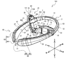
- the HMD 1 includes an image display unit 3, an arm 4, a mounting tool 5, and connection mechanisms 8 and 9.
- the image display unit 3, the arm unit 4, and the coupling mechanisms 8 and 9 constitute an image display unit 2 that can be attached to and detached from the mounting tool 5.
- the upper side, lower side, left side, right side, front side, and rear side of the HMD 1 are defined.
- the upper side, the lower side, the left side, and the right side of the HMD 1 correspond to, for example, the upper side, the lower side, the right side, and the left side of FIG.
- the front side and the rear side of the HMD 1 correspond to, for example, the lower side and the upper side of FIG.
- the upper side, the lower side, the left side, the right side, the front side, and the rear side of the HMD 1 correspond to the user reference directions when the wearing tool 5 is worn by the user.
- the mounting tool 5 is made of a flexible material such as resin or metal (for example, stainless steel).
- the mounting tool 5 is an elongated plate-like member that is formed in a substantially annular shape and that opens on the rear side.
- the shape of the mounting tool 5 according to the first embodiment is a left-right symmetric shape and a vertically symmetric shape.
- the mounting tool 5 has a middle front portion 53, a right front portion 54, a right rear portion 55, a left front portion 56 and a left rear portion 57.
- the front right portion 54 extends between the position 12 and the position 16.
- the position 12 is located in front of the position 16 and on the left side.
- the right front portion 54 curves in a convex shape toward the outside (for example, the front side and the right side) of the region 10 surrounded by the mounting tool 5.
- the right rear portion 55 extends between the position 16 and the position 11.
- the position 11 is located behind the position 16 and on the left side.
- the right rear portion 55 is continuous with the right front portion 54.
- the right rear portion 55 is curved in a convex shape toward the outside (for example, the rear side and the right side) of the region 10.
- the right front part 53 When the configuration of the mounting tool 5 is divided into three parts, that is, the middle front part 53, the right part 51, and the left part 52, the right front part 54 and the right rear part 55 constitute the right part 51.
- the right side portion 51 is connected to the right side of the middle front portion 53 and extends toward the rear side.
- the right portion 51 is curved in a convex shape toward the right side.
- the left front portion 56 extends between the position 14 and the position 17.
- Position 17 is located to the left of position 16.
- the position 14 is a position to the left of the position 12 and is located on the front side and the right side of the position 17.
- the left front portion 56 is curved in a convex shape toward the outside (for example, the front side and the left side) of the region 10.
- the left rear portion 57 extends between the position 17 and the position 13.
- the position 13 is a position to the left of the position 11 and is located on the rear side and the right side of the position 17.
- the left rear portion 57 is continuous with the left front portion 56.
- the left rear portion 57 curves in a convex shape toward the outside (for example, the rear side and the left side) of the region 10.
- the left front portion 56 and the left rear portion 57 constitute the left portion 52 of the wearing tool 5.
- the left side portion 52 is connected to the left side of the middle front portion 53 and extends toward the rear side.
- the left side portion 52 is curved in a convex shape toward the left side.
- the middle front portion 53 extends in the left-right direction between the position 14 and the position 12.
- the middle front portion 53 is continuous with each of the right front portion 54 and the left front portion 56.
- the middle front portion 53 is curved in a convex shape toward the outside (for example, the front side) of the region 10.
- An end 61 is disposed at the center position 21 of the wearing tool 5 in the left-right direction.
- the end 61 is located in front of the wearing tool 5.
- End portions 62 and 63 are arranged at the positions 11 and 13, respectively. Each of the end portions 62 and 63 is located at the very back of the wearing tool 5.
- an end portion 64 is disposed.
- the end portion 64 is located on the rightmost side of the wearing tool 5.
- an end portion 65 is disposed.
- the end portion 65 is located on the leftmost side of the wearing tool 5.
- the wearing tool 5 sandwiches the user's head when wearing.
- the right rear portion 55 and the left rear portion 57 respectively press the user's temporal region.
- the curved shape of the wearing tool 5 varies from part to part so that a pressing force sufficient to support the weight of the HMD 1 can be obtained.
- the position 12 is located at the boundary between the curved shape of the middle front portion 53 and the curved shape of the right front portion 54.
- the position 14 is located at the boundary between the curved shape of the middle front portion 53 and the curved shape of the left front portion 56.
- the position 16 is located at the boundary between the curved shape of the right front portion 54 and the curved shape of the right rear portion 55.
- the position 17 is located at the boundary between the curved shape of the left front portion 56 and the curved shape of the left rear portion 57.
- the radial direction of the curvature circle in contact with the surface facing the region 10 of the wearing tool 5 is defined as the thickness direction of the wearing tool 5.
- the sizes in the thickness direction of the middle front portion 53, the right front portion 54, and the left front portion 56 of the mounting tool 5 are substantially the same size.
- the size in the thickness direction of the right rear portion 55 and the left rear portion 57 is larger than the size in the thickness direction of the middle front portion 53, the right front portion 54, and the left front portion 56, respectively.
- the size in the thickness direction is large.
- the sizes in the vertical direction of the middle front portion 53, the right front portion 54, and the left front portion 56 are substantially the same.
- the sizes in the vertical direction of the right rear portion 55 and the left rear portion 57 are gradually increased from the front side to the rear side, respectively.
- the size in the vertical direction is the largest in the vicinity of the end portions 62 and 63, spaced apart from the end portions 62 and 63 by a predetermined distance, and gradually increases from the vicinity position toward the end portions 62 and 63. Get smaller.
- the right-side part 51 and the left-side part 52 of the mounting tool 5 are respectively provided with table-like protrusions 66 and 67 that protrude into the region 10.
- Holding portions 68 and 69 (described later) extending in a groove shape along the circumferential direction with respect to the protruding direction are provided on the side surfaces of the table-shaped protruding portions 66 and 67 with respect to the protruding direction (for example, the thickness direction).
- the side surfaces of the trapezoidal protrusions 66 and 67 with respect to the thickness direction (hereinafter simply referred to as “side surfaces of the trapezoidal protrusions 66 and 67”) extend along the circumferential direction with the thickness direction as an axis. It is a surface.
- Each of the trapezoidal protrusions 66 and 67 extends between a predetermined first position in the front-rear direction of the mounting tool 5 and a second position on the rear side of the first position. That is, the front end portions 68 ⁇ / b> A and 69 ⁇ / b> A of the holding portions 68 and 69 are provided at the first position of the mounting tool 5. The rear end portions 68 ⁇ / b> B and 69 ⁇ / b> B of the holding portions 68 and 69 are provided at the second position of the wearing tool 5.
- the first position is, for example, the positions 16 and 17 of the end portions 64 and 65 on both sides in the left-right direction of the wearing tool 5.
- the first position is located behind the connection position to which the image display unit 2 is connected (that is, the positions 15A and 15B of the attachment portions 58 and 59 (described later)). Further, the first position is located behind the center of gravity position 25 (described later) of the HMD 1.
- the second positions are the positions 11 and 13 of the end portions 62 and 63 on the rear side in the front-rear direction of the wearing tool 5.
- the trapezoidal protrusion 66 is provided from the position 16 to the position 11 in the right portion 51.
- the trapezoidal protrusion 66 extends along the curved shape of the right portion 51.
- the trapezoidal protrusion 67 is provided from the position 17 to the position 13 in the left portion 52.
- the trapezoidal protrusion 67 extends along the curved shape of the left portion 52. That is, the base-like protrusions 66 and 67 are provided in the right rear portion 55 and the left rear portion 57, respectively.
- the trapezoidal protrusions 66 and 67 have inner surfaces 70 and 71 that face the inside of the region 10, respectively.
- the inner surfaces 70 and 71 protrude in the thickness direction toward the region 10 from the inner surfaces of the right front portion 54 and the left front portion 56. Therefore, the inner surfaces 70 and 71 each have a curved surface shape that follows the curved shapes of the right rear portion 55 and the left rear portion 57. Accordingly, the vertical size of the base protrusions 66 and 67 is also gradually increased from the front side to the rear side, is largest in the vicinity of the end portions 62 and 63, and gradually decreases toward the end portions 62 and 63. Become.
- the holding portions 68 and 69 are, for example, grooves provided (for example, formed) on the wearing tool 5.
- the groove has a groove bottom portion extending along the curved shape of the wearing tool 5 and a pair of side walls extending from both ends in the width direction of the groove bottom portion and facing each other.
- the holding portions 68 and 69 are provided on the base-like projecting portions 66 and 67, respectively.
- the holding portions 68 and 69 are provided on the side surfaces of the table-like projecting portions 66 and 67, respectively. That is, the holding portions 68 and 69 open on the side surfaces of the table-like projecting portions 66 and 67, respectively.
- the groove width direction of the holding portions 68 and 69 coincides with the thickness direction of the wearing tool 5.
- the holding portions 68 and 69 are provided so as to make a round around the base-like projecting portions 66 and 67, respectively.
- the holding portion 68 includes a first holding portion 681, a second holding portion 682, a third holding portion 683, a fourth holding portion 684, a first protruding portion 685, and a second protruding portion 686.
- the holding portion 69 includes a first holding portion 691, a second holding portion 692, a third holding portion 693, a fourth holding portion 694, a first protruding portion 695, and a second protruding portion 696.
- the first holding portions 681 and 691 (see FIG. 2) open on the upper side surfaces of the platform-like projecting portions 66 and 67, respectively.
- the first holding portions 681 and 691 extend from the end portions 64 and 65 to the end portions 62 and 63, respectively.
- the first holding portions 681 and 691 are curved in accordance with the curved shapes of the right side portion 51 and the left side portion 52.
- the second holding portions 682 and 692 (see FIG. 1) open on the lower surfaces of the table-like projecting portions 66 and 67, respectively.
- the second holding portions 682 and 692 extend from the end portions 64 and 65 to the end portions 62 and 63, respectively.
- the second holding portions 682 and 692 are curved in accordance with the curved shapes of the right side portion 51 and the left side portion 52.
- the third holding portions 683 and 693 open on the front side surfaces of the table-like projecting portions 66 and 67, respectively.
- the third holding portion 683 connects the first holding portion 681 and the second holding portion 682 at the position 16 of the right end portion 64.
- the third holding portion 693 connects the first holding portion 691 and the second holding portion 692 at the position 17 of the left end portion 65.
- the fourth holding portions 684 and 694 (see FIG. 2) open on the rear side surfaces of the platform-like projecting portions 66 and 67, respectively.
- the fourth holding part 684 connects the first holding part 681 and the second holding part 682 at the position 11 of the rear end part 62.
- the fourth holding portion 694 connects the first holding portion 691 and the second holding portion 692 at the position 13 of the rear end portion 63.
- the first protrusions 685 and 695 are provided at the end portions 62 and 63 on the rear side of the mounting tool 5, respectively.
- the first projecting portions 685 and 695 are provided on the side walls close to the region 10 among the pair of side walls of the fourth holding portions 684 and 694, respectively.
- the first protrusions 685 and 695 are parts of the side surfaces of the table-like protrusions 66 and 67 adjacent to the openings of the fourth holding parts 684 and 694, respectively, and parts close to the region 10 (for example, the front side). May be provided.
- an area surrounded by the boundary between the side surfaces of the base protrusions 66 and 67 and the surfaces of the pair of side walls of the holding portions 68 and 69 is an opening of a groove (for example, the holding portions 68 and 69).
- the opening refers to a region where the holding portions 68 and 69 are provided on the side surfaces of the trapezoidal protruding portions 66 and 67, that is, a side region which is considered to exist when the holding portions 68 and 69 are not provided.
- the first protrusions 685 and 695 protrude along the groove width direction toward the center of the fourth holding parts 684 and 694 in the groove width direction, respectively.
- the length by which the first protrusions 685 and 695 protrude is not more than half the length of the fourth holding parts 684 and 694 in the groove width direction, respectively.
- the gap between the end portion of the fourth holding portion 684, 694 far from the region 10 and the protruding tip portion of each of the first protruding portions 685, 695 is smaller than the outer diameter of the cable 39.
- the first projecting portions 685 and 695 hold the cable 39 in the groove by pressing the cable 39 disposed in the fourth holding portions 684 and 694.
- a plurality of second protrusions 686 are provided in each of the first holding part 681 and the second holding part 682.
- a plurality of second protrusions 696 are provided in each of the first holding part 691 and the second holding part 692.
- the second protrusion 696 of the first holding portion 691 is one of the pair of side walls 691A and 691B of the first holding portion 691 that is close to the region 10 in the groove width direction (for example, A plurality of side walls 691A) are provided.
- five second protrusions 696 are provided in the first holding part 691.
- the five second protrusions 696 are provided on the side wall 691A at substantially equal intervals along the curved shape of the first holding part 691.
- the second protrusions 696 protrude in the groove width direction toward the side wall 691B.
- the size P by which the second protruding portion 696 protrudes into the first holding portion 691 is, for example, 0.3 mm.
- the second projecting portion 696 extends in the depth direction of the first holding portion 691 (for example, vertically) from the groove bottom portion 691C of the first holding portion 691 toward the opening 697 of the first holding portion 691 along the side wall 691B.
- the groove width W of the holding portions 68 and 69 is, for example, 3.2 mm.
- the outer diameter D of the cable 39 is, for example, 3.2 mm. That is, the size of the gap between the tip 696 A of the second protrusion 696 and the side wall 691 B is smaller than the outer diameter D of the cable 39. Therefore, when the cable 39 is disposed in the first holding portion 691, the cable 39 is pressed against the side wall 691 ⁇ / b> B by the second protruding portion 696, and is thus held in the first holding portion 691.
- each of the configurations of the second protruding portion 696 of the second holding portion 692, the second protruding portion 686 of the first holding portion 681, and the second protruding portion 686 of the second holding portion 682 is the first holding portion described above.
- the configuration of the second projecting portion 696 of 691 is substantially the same, and the description is omitted.
- the cable 39 (see FIG. 2) is pulled out from the image display unit 3.
- the cable 39 electrically connects the image display unit 3 and an external device (not shown).
- the cable 39 is wired along the arm 4 and the mounting tool 5.
- the holding portions 68 and 69 hold a part of the cable 39 wired to the mounting tool 5 in the groove.
- the vertical size (for example, depth) of the holding portions 68 and 69 is larger than the outer diameter of the cable 39.
- a depth H (see FIG. 4) of the holding portions 68 and 69 is, for example, 3.3 mm. Therefore, the cable 39 held in the holding portions 68 and 69 is not exposed to the outside of the groove from the openings of the holding portions 68 and 69.
- the cable 39 drawn out from the image display unit 3 passes through the arm 4 and is inserted into the holding unit 69 on the side close to the arm 4 (for example, the left side).
- the cable 39 is held in the first holding portion 691 of the holding portion 69.
- the cable 39 is inserted into the first holding portion 691 from the front end 69A of the holding portion 69 and wired through the groove.
- the cable 39 is guided to the first holding portion 691 toward the rear end portion 69B of the holding portion 69.
- the cable 39 is pulled out of the mounting tool 5 from the end 69B.
- the wearing tool 5 includes pads 75 to 77 that come into contact with the user's head when worn.
- the pads 75 to 77 are made of an elastic resin such as silicon resin.
- the pad 75 is provided on the inner surface 72 of the middle front portion 53 facing the region 10 and on the portion including the center 21 in the left-right direction of the wearing tool 5. When the HMD 1 is worn, the pad 75 comes into contact with the user's forehead or forehead.
- the pads 76 and 77 are provided on the inner surface 70 of the right rear portion 55 and the inner surface 71 of the left rear portion 57, respectively.
- the pad 76 is provided on the inner surface 70 from the approximate center in the direction along the curved shape of the right rear portion 55 to the end 62.
- the pad 77 is provided on the inner surface 71 from the substantially center to the end portion 63 in the direction along the curved shape of the left rear portion 57.
- the mounting tool 5 has flexibility.
- the mounting tool 5 is separated by the user's hand so that the end 62 and the end 63 are separated from the region 10 (for example, in the left-right direction).
- the pad 75 contacts the user's forehead or forehead, thereby positioning the wearing tool 5 in the front-rear direction on the head.
- the right rear portion 55 and the left rear portion 57 of the mounting tool 5 are biased toward the region 10.
- the pads 76 and 77 are in contact with the right and left heads of the user, respectively.
- the inner surface 70 of the right rear portion 55 presses the right side of the user through the pad 76.
- the inner surface 71 of the left rear portion 57 presses the left side of the user via the pad 77.
- the right rear portion 55 and the left rear portion 57 of the wearing tool 5 respectively press the user's temporal region with a pressing force sufficient to support the weight of the HMD 1.
- the inner surfaces 70 and 71 that are largely provided in the vertical direction have a larger area in contact with the user's temporal region than the inner surface 72 of the middle front portion 53. Therefore, when the mounting tool 5 is mounted on the user's head, the pads 76 and 77 obtain a larger frictional force with the head by increasing the contact area with the head. By ensuring the friction area, the wearing tool 5 can suppress the occurrence of positional deviation in the head.
- Attachment portions 58 and 59 are provided in portions between the front end 61 in the front-rear direction of the mounting tool 5 and the ends 64 and 65 on both sides in the left-right direction, respectively.
- the position 15 ⁇ / b> A where the attachment portion 58 is provided is a position on the right side of the position 21 and on the front side of the position 22. As described above, the position 22 is located at the center of the wearing tool 5 in the front-rear direction.
- the position 15 ⁇ / b> B where the attachment portion 59 is provided is a position on the left side of the position 21 and on the front side of the position 22.
- the attachment portions 58 and 59 are positioned in front of the front end portions 68A and 69A of the holding portions 68 and 69.
- the attachment tool 5 can attach the connection mechanism 8 that connects the attachment tool 5 and the arm 4 to the attachment portions 58 and 59. In the first embodiment, the coupling mechanism 8 is attached to the attachment portion 59.
- the connection mechanism 8 will be
- the mounting portion 58 is formed with two holes 58A that penetrate the mounting tool 5 in the thickness direction (see FIG. 1). Similarly, two holes (not shown) penetrating the mounting tool 5 in the thickness direction are also formed in the attachment portion 59. A screw is inserted through the hole 58A.
- the connection mechanism 8 is attached to the attachment portions 58 and 59 by screws. That is, the image display unit 2 can be attached by selecting one of the attachment portion 58 and the attachment portion 59. When the image display unit 2 is attached to the attachment portion 58, the image display portion 3 is disposed on the right side of the wearing tool 5. The image display unit 3 can cause image light to enter the right eye of the user. When the image display unit 2 is attached to the attachment portion 59, the image display portion 3 is disposed on the left side of the wearing tool 5. The image display unit 3 can cause image light to enter the left eye of the user.
- the image display unit 3 includes a half mirror 35, a lens unit 36, and an image unit 37 in a housing 31.
- the casing 31 has a substantially rectangular parallelepiped shape with curved corners.
- the housing 31 extends long in a predetermined direction (for example, the left-right direction).
- the housing 31 has a hollow box shape.
- the tip 31A which is one end in the direction in which the casing 31 extends, is opened.
- a protruding portion 32 that protrudes rearward is formed on the base end portion 31 ⁇ / b> B that is the other end portion of the housing 31.
- a hole (not shown) penetrating in the front-rear direction is formed at the rear end of the protrusion 32.
- a fixing portion 94 of the coupling mechanism 9 is connected to a position on the rear surface of the housing 31 on the right side of the protruding portion 32.
- the connection mechanism 9 will be described later.
- an image unit 37 is provided in the casing 31 at the base end 31B of the casing 31 at the base end 31B.
- the image unit 37 includes a known liquid crystal panel (not shown) and a control board (not shown).
- the liquid crystal panel generates image light by displaying an image on the left side.
- the control board is disposed on the right side of the liquid crystal panel.
- a cable 39 is connected to the control board.
- the cable 39 passes through the protrusion 32 and is drawn out of the image display unit 3 from the hole at the rear end of the protrusion 32.
- the control board receives image data transmitted from the external device via the cable 39.
- the control board outputs a control signal to the liquid crystal panel and displays an image corresponding to the image data on the liquid crystal panel.
- a two-dimensional display device such as a digital mirror device (DMD) or an organic EL may be used.
- a retinal scanning type projection device (Retinal Scanning Display) that projects light two-dimensionally scanned onto the retina of the user may be used.
- a lens unit 36 is provided on the right side of the image unit 37.
- the lens unit 36 allows the image light emitted from the image unit 37 to pass therethrough and guides it to the distal end portion 31A side.
- the lens unit 36 includes a plurality of lenses (not shown).
- the lens unit 36 is held by the housing 31 so as to be movable in the left-right direction.
- An operation member 38 having a truncated cone shape and having a plurality of irregularities on the side surface is provided on the front surface of the housing 31.
- the operation member 38 is engaged with the lens unit 36 by a groove cam (not shown).
- the lens unit 36 moves toward the distal end portion 31A side or the proximal end portion 31B side.
- the focal length of the image light emitted from the image unit 37 changes. Therefore, the user can adjust the focus by rotating the operation member 38.
- a half mirror 35 is provided at the tip 31A.
- the half mirror 35 has a rectangular plate shape.
- the half mirror 35 can reflect a part (for example, 50%) of the light incident on the reflecting surface and transmit the other part.
- the reflective surface of the half mirror 35 is formed, for example, by vapor-depositing a metal such as aluminum or silver on a transparent resin or glass substrate so as to have a predetermined reflectance (for example, 50%).
- the base end portion 31B of the housing 31 is disposed on the left side of the tip end portion 31A. That is, the image display unit 3 is used in a state of being arranged extending in the left-right direction.
- the half mirror 35 is disposed in front of the user's left eye, for example.
- Half mirror 35 is fixed to tip part 31A in the state where the reflective surface turned to the left side and the back side.
- the image light emitted from the image unit 37 in the housing 31 is condensed when passing through the lens unit 36.
- the condensed image light is incident on the half mirror 35.
- the half mirror 35 reflects the image light to the rear side and makes it incident on the left eye of the user. The user can visually recognize a virtual image based on the image light reflected by the half mirror 35. Further, the half mirror 35 can transmit external light incident from the front side to the rear side.
- the arm 4 has a substantially rod shape.
- the arm 4 is made of resin or metal.
- the upper end portion 4 ⁇ / b> A of the arm 4 is connected to the mounting tool 5 by the connecting mechanism 8. That is, the mounting tool 5 is an example of a connection object to which the arm 4 is connected.
- the lower end 4 ⁇ / b> B of the arm 4 is connected to the image display unit 3 by a connecting mechanism 9.
- the arm 4 holds the image display unit 3 at a position separated from the mounting tool 5.
- the lower end 4B of the arm 4 is disposed below and on the left side of the upper end 4A.
- the arm 4 is curved in a convex shape toward the outside of the region 10. In the first embodiment, the arm 4 is curved in a convex shape toward the left when the HMD 1 is mounted.
- the arm 4 includes a connecting portion 41 at the upper end portion 4A.
- the connecting portion 41 connects the arm 4 to the coupling mechanism 8.
- the connection portion 41 protrudes along the predetermined direction B (see FIG. 6) at the upper end portion 4A.
- the direction B is a direction in which the arm 4 is inclined with respect to the direction C extending from the upper end portion 4A to the lower end portion 4B.
- the connecting portion 41 is formed with a hole (not shown) extending along the direction B.
- a rod body of a ball stud 81 (described later) of the coupling mechanism 8 is inserted into the hole. That is, the rod body of the ball stud 81 extends along the direction B.
- the arm 4 is connected to the coupling mechanism 8 by fixing the rod body to the connection portion 41.
- the connecting mechanism 8 has a rotational degree of freedom of two or more axes.
- the connection mechanism 8 of the first embodiment is a known ball joint type movable part.
- the coupling mechanism 8 includes a ball stud 81, a socket housing portion 82, a fixing nut 83, and a holding portion 84.
- the ball stud 81 is a component in which a rod is connected to a sphere.
- the socket accommodating portion 82 has a cylindrical shape, and accommodates a socket (not shown) that makes spherical contact with the sphere of the ball stud 81.
- the fixing nut 83 is a lid that can be externally fitted to the opening of the socket housing portion 82 and fastened.
- the fixing nut 83 is formed with an insertion hole (not shown) through which the rod body of the ball stud 81 is inserted.
- the ball stud 81 has a movable range in which the rod body can move within the insertion hole with a sphere in contact with the socket as a fulcrum. As shown in FIG. 6, when the shaft of the rod is located at the center of the insertion hole, the ball stud 81 is located at the center of the movable range. At this time, the extending direction of the rod body of the ball stud 81 (for example, the extending direction B of the connecting portion 41) coincides with a direction A (see FIG. 1) described later.
- the movable range of the ball stud 81 is, for example, a predetermined solid angle (for example, within the range of the conical surface) with the direction A as the central axis.
- the holding portion 84 is provided at the end of the socket housing portion 82 opposite to the side on which the fixing nut 83 is fitted.
- the holding portion 84 is a component that attaches the coupling mechanism 8 to the attachment portions 58 and 59 of the mounting tool 5.
- the holding portion 84 includes an upper wall 85, an inner wall 86, and an outer wall 87.
- the upper wall 85 abuts on the upper surface of the mounting portion 58, 59 that faces upward when the HMD 1 is mounted on the head.
- the inner wall 86 abuts against an inner surface facing the inside of the region 10 among the side surfaces of the mounting tool 5 in the attachment portions 58 and 59.
- Outer side wall 87 abuts on the outer surface on the side opposite to the inner surface facing the inside of region 10 among the side surfaces of mounting tool 5 in attachment portions 58 and 59.
- Two holes 87A are formed in the outer side wall 87.
- the arm 4 includes a connecting portion 42 at the lower end 4B.
- the connecting portion 42 connects the arm 4 to the coupling mechanism 9.
- the connection part 42 protrudes along the left-right direction in the lower end part 4B.
- the connecting portion 42 is also formed with a hole (not shown).
- a rod body of a ball stud 91 (described later) of the coupling mechanism 9 is inserted into the hole. That is, the rod body of the ball stud 91 extends along the direction B.
- the arm 4 is connected to the coupling mechanism 9 by fixing the rod body to the connection portion 42.
- the connecting mechanism 9 has two or more degrees of freedom of rotation.
- the connection mechanism 9 of the first embodiment is a known ball joint type movable part, similarly to the connection mechanism 8.
- the connection mechanism 9 includes a ball stud 91, a socket housing portion 92, a fixing nut 93, and a fixing portion 94.
- the configurations of the ball stud 91, the socket accommodating portion 92, and the fixing nut 93 are the same as those of the coupling mechanism 8.
- the shaft of the ball stud 91 is positioned at the center of the insertion hole (not shown) of the fixing nut 93, the ball stud 91 is positioned at the center of the movable range.
- the extending direction of the rod body of the ball stud 91 coincides with the direction A (described later). That is, the movable range of the ball stud 91 is also a predetermined solid angle (for example, within the range of the conical surface) with the direction A as the central axis.
- the fixing portion 94 is provided at an end portion of the socket housing portion 92 opposite to the side on which the fixing nut 93 is fitted (for example, the right end portion of the socket housing portion 92).
- the fixing unit 94 is a component that fixes the coupling mechanism 9 to the image display unit 3.
- the fixing part 94 includes a first fixing part 95, a second fixing part 96, and a stepped connection part 97.
- the first fixing portion 95 is connected to the socket accommodating portion 92.
- the first fixing portion 95 is located on the rear side of the protruding portion 32.
- the left end of the first fixing portion 95 to which the socket accommodating portion 92 is connected is located slightly to the left of the left end of the protruding portion 32.
- the second fixing portion 96 is located forward and to the right of the first fixing portion 95.
- the second fixing part 96 is located on the right side of the protruding part 32 on the rear surface of the image display part 3.
- the second fixing unit 96 is connected to the image display unit 3.
- the second fixing portion 96 is connected to the base end portion 31B of the image display portion 3 on the rear side of the half mirror 35 in the front-rear direction.
- the step-like connecting portion 97 connects the first fixing portion 95 and the second fixing portion 96 in a step shape.
- the step-like connecting portion 97 extends from the front side portion of the first fixing portion 95 across the rear end of the protruding portion 32 in the left-right direction.
- the step-like connecting portion 97 further extends to the left side portion of the second fixing portion 96 along the protruding portion 32 on the right side of the protruding portion 32.
- a hole 97A penetrating in the front-rear direction is formed in a portion where the stepped connection portion 97 crosses the rear end of the protruding portion 32.
- the cable 39 led out from the hole 97A at the rear end of the protrusion 32 is inserted into the hole.
- the HMD 1 configured as described above takes the form described below when the image display unit 2 is attached to the attachment portion 58 and the coupling mechanisms 8 and 9 are in the center of the movable range.
- the coupling mechanism 8 is provided so as to protrude to the outside of the region 10 with respect to the mounting tool 5 in a plan view.
- the upper end portion 4 ⁇ / b> A of the arm 4 is connected to the coupling mechanism 8 on the outer side of the region 10 than the coupling mechanism 8.
- the lower end 4B of the arm 4 is disposed below the upper end 4A.
- the coupling mechanism 9 is connected to the proximal end portion 31 ⁇ / b> B of the image display unit 3 on the rear side of the image display unit 3. Since the housing 31 of the image display unit 3 extends in the left-right direction, the distal end portion 31A is disposed to the right of the proximal end portion 31B.
- the half mirror 35 is disposed in front of the left eye of the user.
- the cable 39 drawn from the image display unit 3 travels along the arm 4 and is wired on the upper side of the mounting tool 5 in the mounting unit 59.
- the cable 39 is wired in the first holding portion 691 at the front end 69A of the holding portion 69.
- the first position where the end 69 ⁇ / b> A is disposed is the position 17 of the left end 65 of the wearing tool 5. Therefore, the HMD 1 can be extended in the first holding portion 691 by extending the cable 39 from the attachment portion 59 to the rear side as it is.
- the first position where the end 69 ⁇ / b> A is arranged is a position behind the position 25 of the center of gravity of the HMD 1 in a state where the cable 39 is not held by the holding part 69. Further, the positions 15A and 15B of the attachment portions 58 and 59 to which the image display unit 2 can be attached are positioned before the position 25 of the center of gravity.
- the position 25 of the center of gravity of the HMD 1 is a position of a point that can be considered that the resultant force of gravity acting on each part of the HMD 1 acts.
- the position 25 of the center of gravity changes depending on the positional relationship among the wearing tool 5, the arm 4, and the image display unit 3.
- maintenance part 69, and the ball studs 81 and 91 of the connection mechanisms 8 and 9 are each arrange
- the position 25 of the center of gravity is obtained as follows. For example, the HMD 1 is hung with a thread attached to an arbitrary position of the wearing tool 5 and the direction of the extension line of the thread is recorded. The HMD 1 is hung with a thread attached at an arbitrary position different from the tip of the wearing tool, and the direction of the extension line of the thread is recorded.
- the position of the intersection of the two recorded extension lines is obtained and set as the position 25 of the center of gravity of HMD1.
- the position 25 of the center of gravity of the HMD 1 obtained in this way is desirably located on the left side of the center position 21 in the left-right direction and on the front side of the center position 22 in the front-rear direction.
- the weight of the image display unit 3 and the arm 4 is applied to the position 15B of the mounting tool 5 to which the arm 4 is connected.
- the position 15B is on the front side of the holding unit 69, and a moment that rotates the front side downward from the position 25 of the center of gravity acts on the HMD1 due to the weight of the image display unit 3 and the arm 4. Since the first position is located behind the center of gravity position 25, when the cable 39 is held by the holding portion 69, the weight of the cable 39 is applied to the rear portion of the HMD 1 rather than the center of gravity position 25. The moment for rotating the rear side of the HMD 1 downward increases. Therefore, the moment acting on the HMD 1 due to the weight of the image display unit 3 and the arm 4 is reduced.
- the HMD 1 can improve the weight balance, and can prevent the image display unit 3 and the arm 4 from falling off the forehead due to their own weight.
- the moment that acts on the HMD 1 due to the weight of the image display unit 3 and the arm 4 can be reduced by holding the cable 39 in the holding unit 68, as described above. It is.
- the length at which the first position and the attachment portion 59 are separated is equal to or larger than the minimum bending diameter determined by the physical property value of the cable 39.
- the length is closer to the minimum bending diameter. The shorter the distance between the first position and the attachment portion 59 is, the less likely the cable 39 is to be hooked when the HMD 1 is attached / detached or used. If the length at which the first position and the attachment portion 59 are separated is shorter than the minimum bending diameter, the cable 39 may be subjected to a bending load.
- the outer diameter D of the cable 39 wired in the first holding portion 691 is smaller than the depth H of the first holding portion 691. Therefore, the cable 39 wired in the first holding part 691 is not exposed from the opening 697 of the first holding part 691.
- the outer diameter D of the cable 39 is larger than the size of the gap between the tip 696A of the second protrusion 696 and the side wall 691B. Therefore, the cable 39 wired in the first holding portion 691 is pressed against the side wall 691B by the second protruding portion 696.
- the trapezoidal protrusion 67 protrudes toward the region 10 in the left portion 52.
- the cable 39 is usually fitted into the first holding portion 691 from within the region 10 by the user's hand inserted into the region 10. That is, when the cable 39 is fitted into the first holding portion 691, the cable 39 is pressed downward and from the inside of the region 10 to the outside.
- the second protrusion 696 is provided on the side wall 691 ⁇ / b> A close to the region 10. Therefore, the cable 39 is easily pushed over the second projecting portion 696 and is wired in the first holding portion 691 by being pressed downward and from the inside of the region 10 to the outside.
- the cable 39 is pressed against the second protrusion 696 when pressed downward and from the inside of the region 10 to the outside. Therefore, when the cable 39 is pressed by the hand inserted into the region 10, if the second protrusion 696 is provided on the side wall 691B, the insertion of the cable 39 into the first holding part 691 is not performed. Compared to the case where the portion 696 is provided on the side wall 691A, it may be difficult.
- the cable 39 is wired toward the rear end portion 69 ⁇ / b> B of the holding portion 69 while being held in the first holding portion 691. Since the first holding part 691 has the opening 697 on the upper side of the mounting tool 5, the cable 39 can be received in the direction of gravity, and the cable 39 can be prevented from falling off due to gravity.
- the cable 39 is wired from the first holding part 691 to the fourth holding part 694.
- the first protrusion 695 protruding from one end of the fourth holding part 694 holds the cable 39 in the opening of the fourth holding part 694 and holds it in the fourth holding part 694.
- the position where the first protrusion 695 presses the cable 39 is a position where the cable 39 is taken out from the fourth holding portion 694.
- the fourth holding portion 694 opens at the rear side surface of the trapezoidal protruding portion 67 and is connected to the first holding portion 691.
- the first protrusion 695 holds the back of the cable 39 forward. Therefore, when the cable 39 is wired from the first holding portion 691 to the fourth holding portion 694, the cable 39 is guided by the first projecting portion 695 and below the mounting tool 5 along the shape of the fourth holding portion 694. Bent in a direction extending toward In this manner, the HMD 1 routes the cable 39 extending from the attachment portion 59 to the rear side through the arm 4 from the front end portion 69A into the holding portion 69, and from the rear end portion 69B to the lower side of the mounting tool 5. Can be hung. Since the HMD 1 holds the cable 39 in the holding portion 69, the cable 39 can be easily detached.
- the configuration of the first holding unit 691 of the holding unit 69 and the configuration of the second holding unit 692 of the holding unit 69 are substantially the same. Therefore, when the connecting mechanism 8 of the image display unit 2 is connected to the mounting portion 59 in a state where the vertical direction of the mounting tool 5 is reversed, the HMD 1 connects the cable 39 in the second holding portion 692 and the first holding portion. Wiring can be performed in the same manner as 691.
- the mounting tool 5 includes a pair of attachment portions 58 and 59.
- the configuration of the first holding unit 691 of the holding unit 69 and the configuration of the first holding unit 681 of the holding unit 68 are also substantially the same.
- the HMD 1 can wire the cable 39 in the first holding portion 681 in the same manner as the first holding portion 691. Furthermore, the configuration of the first holding unit 691 of the holding unit 69 and the configuration of the second holding unit 682 of the holding unit 68 are substantially the same. Therefore, when the connecting mechanism 8 of the image display unit 2 is connected to the mounting portion 58 in a state where the vertical direction of the mounting tool 5 is reversed, the HMD 1 causes the cable 39 to be in the second holding portion 682 and the first holding portion. Wiring can be performed in the same manner as 691.
- the cable 39 is held by the holding portions 68 and 69 from the first position to the second position on the occipital side. Therefore, the gap generated between the cable 39 and the mounting tool 5 can be reduced. As a result, the cable 39 is unlikely to be caught or caught when the HMD 1 is attached / detached or used, and therefore, the cable 39 is not easily detached from the mounting tool 5. On the other hand, when removing the image display unit 3 and the arm 4 from the mounting tool 5, the cable 39 can be easily detached from the mounting tool 5 simply by pulling the cable 39 out of the groove.
- the holding parts 68 and 69 extend to the rear end parts 62 and 63 of the wearing tool 5, the cable 39 held by the holding parts 68 and 69 is not easily caught or caught when the HMD 1 is attached or detached. It is hard to come off from the wearing tool 5.
- the mounting tool 5 can hold the cable 39 in the holding portions 68 and 69 by the first projecting portions 685 and 695 at the rear end portions 62 and 63. Thanks to the first protrusions 685 and 695, the cable 39 is unlikely to come off the mounting tool 5. Further, the first projecting portions 685 and 695 hold the cable 39 at a position where the cable 39 is taken out from the holding portions 68 and 69, so that when the HMD 1 is attached, the portion where the cable 39 is taken out is below the fitting 5. Can guide you to head.
- the cable 39 passing through the arm 4 extends from the mounting portions 58 and 59 to the front side and then turns back to the first side. It is hold
- the cable 39 passing through the arm 4 extends from the attachment portions 58 and 59 to the rear side, and the holding portions 68 and 69 from the first position as they are. And is wired in a path toward the rear side of the mounting tool 5. Therefore, the possibility that the cable 39 is detached from the mounting tool 5 can be reduced.
- the weight of the image display unit 3 and the arm 4 is applied to the position 15B of the mounting tool 5 to which the arm 4 is connected.
- the position 15B is on the front side of the holding unit 69, and a moment that rotates the front side downward from the position 25 of the center of gravity acts on the HMD1 due to the weight of the image display unit 3 and the arm 4.
- the cable 39 is held by the holding portion 69, the weight of the cable 39 is applied to the rear portion of the HMD 1 with respect to the position 25 of the center of gravity. Therefore, the moment acting on the HMD 1 due to the weight of the image display unit 3 and the arm 4 is reduced. Accordingly, the HMD 1 can improve the weight balance, and can prevent the image display unit 3 and the arm 4 from falling off the forehead due to their own weight.
- the holding portions 68 and 69 are formed inside the ring of the open annular mounting tool 5, the cable 39 held by the holding portions 68 and 69 is difficult to be caught from the outside of the mounting tool 5 and is detached from the mounting tool 5. Hateful.
- the holding portions 68 and 69 are provided on the right side portion 51 and the left side portion 52 of the wearing tool 5, respectively.
- the connection destination of the arm 4 is changed in the left-right direction of the mounting tool 5, for example, from the left attachment portion 59 to the right attachment portion 58, the cable 39 is held by the holding portion 68 close to the changed attachment portion 58. be able to.
- the holding parts 68 and 69 have an opening on the upper side in the direction in which the wearing tool 5 is used. Therefore, the HMD 1 can prevent the cable 39 from being detached from the holding portions 68 and 69 due to gravity.
- the HMD 1 can invert the arm 4 in the third direction (for example, the vertical direction). That is, the image display unit 3 can be moved from the lower side to the upper side with respect to the wearing tool 5 via the arm 4 by the connecting mechanism 8. If the mounting tool 5 is mounted upside down, the HMD 1 can rearrange the image display unit 3 from the left eye side to the right eye side.
- the holding parts 68 and 69 have first holding parts 681 and 691 and second holding parts 682 and 692, respectively. Even if the mounting tool 5 is used by being inverted in the vertical direction, the HMD 1 can change the holding of the cable 39 from, for example, the first holding portion 681, 691 to the second holding portion 682, 692, so that the cable 39 is pulled by gravity. It is possible to prevent the holders 68 and 69 from being detached.
- the cable 39 is not exposed from the holding portions 68 and 69 while being held by the holding portions 68 and 69, it is difficult to be caught or caught when the HMD 1 is attached or detached, or to be detached from the mounting tool 5.
- the second protrusions 686 and 696 can hold the cable 39 in the holding portions 68 and 69. Therefore, the cable 39 is difficult to come off from the mounting tool 5.
- the cable 39 may not contact the 2nd protrusion part 686,696.
- the cable 39 may come into contact with the second protruding portions 686 and 696, and the covering portion may be worn.
- the second protrusions 686 and 696 can maintain the state in which the cable 39 is in contact with the cable 39 while the cable 39 is in contact with the bottom of the groove. Therefore, the HMD 1 can prevent the cable 39 from being worn and can prevent the cable 39 from being detached from the holding portions 68 and 69.
- the wearing tool 5 is curved at least partially, so that the gap between the wearing tool 5 and the head can be reduced along the curved shape of the head. Since the gap between the mounting tool 5 and the head is small, it is possible to reduce the possibility that a portion of the cable 39 that is not held in the holding portions 68 and 69 is disposed between the mounting tool 5 and the head. Therefore, the cable 39 is unlikely to be caught or caught during use in the gap between the mounting tool 5 and the head, and is difficult to be detached from the mounting tool 5.
- the cable 39 is not fixed to the arm 4. Therefore, for example, when the arm 4 rotates, the cable 39 may be entangled with the arm 4 or the cable 39 may block the user's field of view. Therefore, the cable may be an obstacle for the user.
- Another aspect of the present disclosure provides a head-mounted display and an image display unit in which the arm and the image display unit can be easily attached and detached, and the cable is less likely to be an obstacle to the user.
- the second embodiment differs from the first embodiment in the structure of the arm.
- the HMD 101 is an optically transmissive HMD that can be worn on the user's head, like the HMD 1 in the first embodiment.
- the HMD 101 includes a mounting tool 5 and an image display unit 7.
- the wearing tool 5 can be worn on the user's head.
- the mounting tool 5 includes a first cable holding unit 60.
- the first cable holding unit 60 holds the cable 39.
- the image display unit 7 can be attached to and detached from the mounting tool 5.
- the mounting tool 5 in the second embodiment has the same configuration as the mounting tool 5 in the first embodiment (see FIGS. 1 to 4 and FIG. 8).
- the first cable holding unit 60 includes holding units 68 and 69.
- the holding portions 68 and 69 in the second embodiment have the same configuration as the holding portions 68 and 69 (see FIGS. 1, 2, 4, and 8) in the first embodiment, respectively.
- the illustration of the pads 75 to 77 is omitted.
- the image display unit 7 will be described with reference to FIGS.
- the image display unit 7 includes an arm 104, a coupling mechanism 80, an image display unit 30, a coupling mechanism 90, a second cable holding unit 400, and a cable 39.
- the connection mechanisms 80 and 90 are known ball joint type movable mechanisms, similarly to the connection mechanisms 8 and 9 in the first embodiment.
- the arm 104 can be rotated by a connecting mechanism 80.
- the image display unit 30 can be rotated by a connecting mechanism 90. That is, the relative position of the image display unit 7 with respect to the mounting tool 5 can be displaced depending on the usage state of the HMD 101. In the following description, the configuration of the image display unit 7 in the use position will be described for convenience.
- the use position is a position where the image display unit 7 is arranged when the HMD 101 mounted on the head emits image light to the user's eyes.
- the use position of the image display unit 7 in 2nd Embodiment is a position where the half mirror 35 is arrange
- the arm 104 has a substantially rod shape.
- the arm 104 is disposed on the left side of the mounting tool 5.
- the arm 104 is made of resin or metal.
- One end portion 4A of the arm 104 is rotatably connected to the mounting tool 5 by a connecting mechanism 80 described later.
- the other end 4B of the arm 104 is rotatably connected to the image display unit 30 by a connecting mechanism 90 described later.
- the arm 104 extends in a direction intersecting with the front-rear direction (for example, the vertical direction) when viewed from the front at the use position. More specifically, the arm 104 extends in a direction in which the lower end is inclined forward with respect to the vertical direction.
- the arm 104 has an inner surface 6.
- the inner surface 6 is the right surface of the arm 104.
- the inner surface 6 faces in a direction (for example, right direction) from the arm 104 toward the mounting tool 5 and the half mirror 35.
- the connection mechanism 80 connects the mounting tool 5 and the arm 104.
- the coupling mechanism 80 includes an inner mounting member 230, an outer mounting member 240, and the first ball joint 20.
- the inner attachment member 230 is a plate-like member that is attached to the inner surface of the left front portion 56.
- the inner surface of the left front portion 56 is a surface facing the region 10 in the left front portion 56.
- the inner attachment member 230 includes a base portion 232.
- the base portion 232 extends and contacts the inner surface of the left front portion 56 substantially in parallel.
- the base portion 232 is provided with a cylindrical portion 234.
- the cylindrical portion 234 protrudes from the base portion 232 toward the outside of the region 10 and enters the through hole 56 ⁇ / b> A of the left front portion 56.
- the cylindrical hole of the cylindrical portion 234 is a fastening hole.
- a screw thread is formed in the cylindrical hole of the cylindrical portion 234.
- the outer mounting member 240 includes a connecting portion 242.
- the connecting portion 242 is provided so as to cover the upper side portion, the front side portion, and the lower side portion of the left front portion 56.
- the connecting portion 242 is connected to the inner mounting member 230.
- the connecting portion 242 contacts an outer surface that is the surface opposite to the inner surface of the left front portion 56.
- the connecting portion 242 is disposed on the side opposite to the inner attachment member 230 with respect to the left front portion 56.
- the connecting portion 242 is formed with an insertion hole 242A facing the through hole 56A of the left front portion 56.
- the screw 101 is inserted through the insertion hole 242A.
- the screw 101 inserted through the insertion hole 242A enters the through hole 56A.
- the screw 101 is fastened to the cylindrical hole of the cylindrical portion 234 that has entered the through hole 56A. Thereby, the inner side attachment member 230 and the outer side attachment member 240 are connected.
- the connecting portion 242 is provided with a cylindrical portion 244 positioned substantially coaxially with the insertion hole 242A.
- the cylindrical portion 244 protrudes toward the opposite side of the left front portion 56 with respect to the connecting portion 242.
- a screw thread is formed on the outer peripheral surface of the cylindrical portion 244.
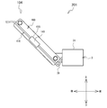
- the first ball joint 20 includes a first ball stud 211 and a first socket 221.
- the first ball stud 211 has a first rod portion 21A and a first sphere portion 21B.
- the first rod portion 21A is a rod-shaped part.
- a fastening hole is formed in one end portion 21C of the first rod portion 21A.
- a screw thread is formed on the inner peripheral surface surrounding the fastening hole of the one end portion 21C.
- a cylindrical portion 411 is provided at the upper end portion of the inner surface 6 of the arm 104 (see FIG. 11).
- 41 A of insertion holes are formed in the wall part located in the left side of the cylinder hole of the cylindrical part 411. As shown in FIG. The insertion hole 41A faces the fastening hole of the one end portion 21C.
- a screw 73 is inserted into the insertion hole 41A and is tightened in the fastening hole of the one end portion 21C.
- the one end portion 21 ⁇ / b> C is fastened to the cylindrical portion 411. That is, one end portion 21 ⁇ / b> C of the first rod portion 21 ⁇ / b> A is connected to the arm 104.
- the position where the one end portion 21C and the cylindrical portion 411 are referred to as a position R.
- the position R is a position where the arm 104 and the first rod portion 21A are connected.
- the first rod portion 21A passes through the cylindrical hole of the cylindrical portion 411.
- the first sphere portion 21B is a spherical portion provided in the other end portion 21D.
- the other end portion 21D is an end portion opposite to the one end portion 21C of the first rod portion 21A.
- the diameter of the first spherical portion 21B is larger than the outer diameter of the first rod portion 21A and smaller than the inner diameter of the cylindrical portion 244.
- the first sphere part 21B is disposed inside the cylindrical part 244.
- the first sphere part 21 ⁇ / b> B contacts the cylindrical part 244 via the right contact member 79 and the left contact member 78.
- the right contact member 79 and the left contact member 78 are elastically deformable rubbers that function as cushioning materials.
- the right contact member 79 is formed in a substantially hemispherical shape and contacts the right portion of the first sphere portion 21B.
- the left contact member 78 is formed in a substantially cylindrical shape and contacts the left portion of the first sphere portion 21B.
- the right contact member 79 projects leftward from the cylindrical hole of the cylindrical portion 244.
- the first rod portion 21 ⁇ / b> A passes through the cylindrical hole of the left contact member 78.
- the first socket 221 is a substantially cylindrical member disposed coaxially with the cylindrical portion 244 of the outer mounting member 240 and surrounds the cylindrical portion 244 and the left contact member 78.
- the first socket 221 includes a first bottom portion 22A and a first side portion 22B.
- the first bottom portion 22 ⁇ / b> A is a substantially circular plate-like portion and is disposed on the right side of the cylindrical portion 244.
- a first hole portion 23 that is a circular through hole is formed in a substantially central portion of the first bottom portion 22A.
- a left contact member 78 is disposed inside the first hole portion 23.
- the first rod portion 21 ⁇ / b> A passes through the first hole portion 23.
- the first side portion 22B is a substantially cylindrical portion extending from the peripheral end portion of the first bottom portion 22A toward the right side.
- a thread is formed on the inner peripheral surface of the first side portion 22B.
- the first socket 221 is screwed into the outer mounting member 240 by fitting the thread of the first side part 22 ⁇ / b> B into the thread of the cylindrical part 244. That is, the first socket 221 is connected to the mounting tool 5.
- a position 15B where the outer mounting member 240 and the left front portion 56 are connected is a position where the first socket 221 and the mounting tool 5 are connected.
- the position 15B of the second embodiment is on the rear side and the left side of the position 14 (see FIG. 9), and is on the left side and the front side of the position 17 (see FIG. 9). That is, the position 15B is located on the front side of the first cable holding unit 60 (see FIG. 9).
- the first socket 221 moves in the direction of the arrow 24 from the arm 104 side toward the mounting tool 5 side.
- the right contact member 79 and the left contact member 78 sandwich the first sphere 21B from both sides in the left-right direction.
- the first spherical body portion 21 ⁇ / b> B can rotate in any direction by sliding with respect to the right contact member 79 and the left contact member 78.
- the first socket 221 supports the first spherical body portion 21 ⁇ / b> B slidably via the right contact member 79 and the left contact member 78. Therefore, the first ball joint 20 can rotate the arm 104 in any direction with respect to the mounting tool 5. Note that the rotation of the arm 104 is limited when the first rod portion 21 ⁇ / b> A comes into contact with the left contact member 78.
- the image display unit 30 is movably supported by the arm 104 via a connecting mechanism 90 described later.
- the image display unit 30 includes a housing 31.
- the casing 31 in the second embodiment has the same shape as the casing 31 in the first embodiment (see FIGS. 1 to 3 and 5 to 7).
- a protruding portion 322 that protrudes rearward is formed on the base end portion 31 ⁇ / b> B that is the other end portion of the housing 31.
- a fastening hole 32A is formed in the rear portion of the right surface of the protruding portion 322 (see FIG. 13).
- a screw thread is formed in the fastening hole 32A.
- the connecting mechanism 90 connects the image display unit 30 and the arm 104.
- the connection mechanism 90 includes a cylindrical member 900 and a second ball joint 700.
- the cylindrical member 900 is a cylindrical member that is long in the left-right direction, and is attached to the left surface of the protruding portion 322.
- the cylindrical member 900 has a bottom 922.
- the bottom part 922 is a substantially circular plate-like part, and contacts the left surface of the protruding part 322.
- An insertion hole 92 ⁇ / b> A is formed at the center of the bottom 922.
- the insertion hole 92 ⁇ / b> A faces the fastening hole 32 ⁇ / b> A of the protruding portion 322.
- the screw 102 is inserted into the insertion hole 92A and screwed into the fastening hole 32A.
- the cylindrical member 900 is connected to the protruding portion 322.
- a side portion 944 is provided at the peripheral end portion of the bottom portion 922.
- the side portion 944 is a cylindrical portion that extends leftward from the bottom portion 922.
- a thread is formed on the outer peripheral surface of the side portion 944.
- the second ball joint 700 includes a second ball stud 710 and a second socket 720.
- the second ball stud 710 has a second rod portion 71A and a second sphere portion 71B.
- the second rod portion 71A is a rod-shaped part.
- a fastening hole is formed in one end portion 71C of the second rod portion 71A.
- a screw thread is formed in the fastening hole of the one end portion 71C.
- a cylindrical portion 44 is provided at the lower end of the inner surface 6 of the arm 104 (see FIG. 11).
- An insertion hole 44 ⁇ / b> A is formed in the wall portion located on the left side of the cylindrical hole of the cylindrical portion 44.
- the insertion hole 44A faces the fastening hole of the one end portion 71C.
- the screw 103 is inserted into the insertion hole 44A and is tightened in the fastening hole of the one end portion 71C.
- the one end portion 71 ⁇ / b> C is fastened to the cylindrical portion 44. That is, one end portion 71 ⁇ / b> C of the second rod portion 71 ⁇ / b> A is connected to the arm 104.
- the arm 104 is connected to the protruding portion 322 of the image display unit 30 via the one end portion 71C.
- a position S is a position where the one end portion 71C of the second rod portion 71A and the cylindrical portion 44 are in contact with each other.
- the position S is a position where the second rod portion 71A and the arm 104 are connected, and is a position where the arm 104 and the image display unit 30 are connected.
- the second sphere portion 71B is a spherical portion provided at the other end portion 71D.
- the other end 71D is an end opposite to the one end 71C of the second rod 71A.
- the diameter of the second spherical portion 71B is larger than the outer diameter of the second rod portion 71A and smaller than the inner diameter of the cylindrical portion 44.
- the second sphere portion 71 ⁇ / b> B is disposed inside the side portion 944 of the cylindrical member 900.
- the second sphere portion 71B is in contact with the cylindrical member 900 via the right contact member 179 and the left contact member 178.
- the right contact member 179 and the left contact member 178 are elastically deformable rubbers that function as cushioning materials.
- the right contact member 179 is formed in a substantially hemispherical shape and contacts the right portion of the second sphere portion 71B.
- the left contact member 178 is formed in a substantially cylindrical shape and contacts the left portion of the second sphere portion 71B.
- the second rod portion 71A passes through the cylindrical hole of the left contact member 178.
- the right contact member 179 protrudes leftward from the side portion 944.
- the second socket 720 is a substantially cylindrical member disposed coaxially with the cylindrical member 900, and surrounds the side portion 944 and the left contact member 178.
- the second socket 720 includes a second bottom portion 72A and a second side portion 72B.
- the second bottom portion 72A is a substantially circular plate-shaped part.
- the second bottom portion 72 ⁇ / b> A is disposed on the right side of the side portion 944.
- a second hole 33 which is a circular through hole, is formed in a substantially central portion of the second bottom portion 72A.
- a left contact member 178 is disposed inside the first hole 23. That is, the second rod portion 71A passes through the second hole portion 33.
- the second side portion 72B is a substantially cylindrical portion extending from the peripheral end portion of the second bottom portion 72A toward the right side.
- a screw thread is formed on the inner peripheral surface of the second side portion 72B.
- the second socket 720 is screwed into the cylindrical member 900 by fitting the screw thread of the second side part 72 ⁇ / b> B into the screw thread of the side part 944. That is, the second socket 720 is connected to the protrusion 322 of the image display unit 30.
- the second socket 720 moves in the direction of the arrow 26 from the arm 104 side toward the mounting tool 5 side.
- the right contact member 179 and the left contact member 178 sandwich the second sphere part 71B from both sides in the left-right direction.
- the second spherical portion 71B can rotate in any direction by sliding with respect to the right contact member 179 and the left contact member 178.
- the second socket 720 slidably supports the second sphere part 71B via the right contact member 179 and the left contact member 178. Therefore, the second ball joint 700 can rotate the image display unit 30 in an arbitrary direction with respect to the arm 104. The rotation of the image display unit 30 is limited when the second rod portion 71A comes into contact with the left contact member 178.
- the second cable holding portion 400 is provided (for example, formed) on the inner surface 6 of the arm 104.
- the 2nd cable holding part 400 of 2nd Embodiment is a groove
- the second cable holding portion 400 is located on the rear side of the center of the inner surface 6 in the width direction of the arm 104.
- the width direction of the arm 104 is a direction (for example, the front-rear direction) perpendicular to the longitudinal direction of the arm 104 and parallel to the inner surface 6.
- the second cable holding portion 400 is located on the rear side of the cylindrical portion 411 and the first rod portion 21A. Further, the second cable holding part 400 is located on the rear side of the cylindrical part 44 and the second rod part 71A. That is, the second cable holding part 400 is located on the rear side of each of the position R and the position S.
- the second cable holding part 400 extends to the upper end of the arm 104. In other words, the second cable holding unit 400 extends to the end of the arm 104 in the direction from the image display unit 30 toward the position 15B in the longitudinal direction of the arm 104.
- the second cable holding part 400 extends to the lower end of the arm 104. In other words, the second cable holding unit 400 extends to the end of the arm 104 in the direction from the position 15 ⁇ / b> B to the image display unit 30 in the longitudinal direction of the arm 104.
- the second cable holding part 400 has a groove bottom part and a pair of side wall parts.
- the groove bottom portion extends along the longitudinal direction of the arm 104.
- the pair of side wall portions respectively extend from both ends of the groove bottom in the groove width direction and face each other.
- the groove width direction of the second cable holding portion 400 matches the width direction of the arm 104, for example.
- the horizontal size (for example, depth) of the second cable holding unit 400 and the groove width of the second cable holding unit 400 may be generally the same as those of the first cable holding unit 60, respectively.
- the cable 39 electrically connects the image display unit 30 and an external device (not shown).
- One end of the cable 39 is connected to a control board (not shown) of the image unit 37 (see FIG. 9).
- the cable 39 connected to the control board is drawn out from a connection hole (not shown) formed on the rear surface of the housing 31.
- the connection hole is a hole formed in a portion of the rear surface of the housing 31 that is on the left side of the protruding portion 322 and on the right side of the arm 104. That is, the cable 39 is connected to the housing 31 of the image display unit 30 between the arm 104 and the half mirror 35 (see FIG. 9).
- the connection hole is located at the center of the rear surface of the housing 31 in the vertical direction.
- the cable 39 passes under the second socket 720 and is detachably pushed into the second cable holding unit 400. A portion of the cable 39 below the second socket 720 and on the right side of the other end 4B of the arm 104 is loose (see FIG. 9). A portion of the cable 39 that is pushed into the second cable holding portion 400 extends substantially linearly along the inner surface 6 of the arm 104.
- the groove width of the second cable holding portion 400 may be slightly smaller than the diameter of the cable 39.
- the cable 39 is detachably pushed into the second cable holding portion 400 from the lower end to the upper end of the arm 104.
- the cable 39 is detachably held by the second cable holding portion 400 in such a posture that the rear side of the cylindrical portions 411 and 44 passes along the longitudinal direction of the arm 104.
- the diameter of the cable 39 is smaller than the depth of the second cable holding part 400. Therefore, the portion of the cable 39 that is pushed into the second cable holding portion 400 is less likely to protrude to the right side of the inner surface 6 of the arm 104.
- the cable 39 held by the second cable holding unit 400 is pulled out from the upper end of the arm 104.
- the cable 39 is pushed into the holding portion 69 from the front end of the first holding portion 691 (that is, the end portion 69A in FIG. 2) to the lower end of the second holding portion 694.
- the cable 39 can be detached from the holding portion 69.
- a portion of the cable 39 between the upper end of the arm 104 and the front end of the first holding portion 691 passes through the rear side of the position 15B and passes through the upper side of the wearing tool 5.
- portions of the cable 39 that are wired to the lower end of the arm 104, the upper end of the arm 104, and the front end of the first holding portion 691 pass through the rear side of the position 15B along the longitudinal direction of the arm 104.
- the cable 39 is held by the second cable holding unit 400 in a posture that passes the rear side of the position 15B along the longitudinal direction of the arm 104.
- a portion of the cable 39 between the upper end of the arm 104 and the front end of the first holding portion 691 is loose (see FIG. 9).
- the cable 39 drawn from the rear end of the second holding unit 684 is connected to an external device (not shown) such as a video source device or a relay that relays connection with the video source device.
- the image display unit 7 can be connected with the mounting tool 5 so that an image light can be inject
- a connection mechanism 80 is attached to the right front portion 54 of the mounting tool 5, and an alternative arm (not shown) is connected to the connection mechanism 80.
- the substitute arm is an arm that is symmetrical to the arm 104 with respect to a virtual plane that is orthogonal to the left-right direction and passes through the position 21.
- the substitute arm supports the image display unit 30 via the coupling mechanism 90.
- the cable 39 is detachably pushed into the second cable holding portion (not shown) provided in the alternative arm and the holding portion 68 of the first cable holding portion 60.
- the outline of position adjustment of the image display unit 7 when the wearing tool 5 is worn on the user's head will be described with reference to FIGS.
- the image display unit 7 before the position adjustment is arranged at a position different from the use position.
- the user holds the image display unit 7 with his left hand and rotates the arm 104.
- the arm 104 rotates to a predetermined position.
- the image display unit 30 moves as the arm 104 rotates.
- the portion of the cable 39 that is pushed into the second cable holding portion 400 does not protrude to the right of the inner surface 6, so that it is difficult to contact the rotating first rod portion 21 ⁇ / b> A. Therefore, the cable 39 is not easily disturbed by the user.
- a portion of the cable 39 between the upper end of the arm 104 and the front end of the first holding portion 691 is loose, so that it is difficult to assume an extended posture regardless of the rotational position of the arm 104. Since the cable 39 is difficult to restrict the rotation of the arm 104, it is difficult for the user to get in the way.
- the user rotates the arm 104 to a predetermined rotation position and then rotates only the image display unit 30 with respect to the arm 104.
- the image display portion 30 rotates to a position where the half mirror 35 is disposed in front of the user's left eye.
- the image display unit 7 moves to the use position.
- the portion of the cable 39 that is pushed into the second cable holding portion 400 does not protrude to the right of the inner surface 6, so that it is difficult to contact the rotating second rod portion 71 ⁇ / b> A.
- the portion of the cable 39 below the second socket 720 and on the right side of the other end 4B of the arm 104 is loose, so that it is in an extended posture regardless of the rotational position of the image display unit 30.
- the image display unit 30 is difficult to pull. That is, the cable 39 is difficult to limit the rotation of the image display unit 30. Therefore, the cable 39 is unlikely to get in the way for the user.
- the mounting tool 5 is mounted on the user's head, the image display unit 7 is disposed at the use position, and the HMD 101 is used.
- the cable 39 is held by the second cable holding unit 400 in a posture that passes the rear side of the position 15B along the longitudinal direction of the arm 104. Therefore, when the HMD 101 is used, the cable 39 is not arranged between the half mirror 35 and the left eye of the user, and thus it is difficult to block the user's field of view. Even if the cable 39 is detached from the second cable holding unit 400 during use of the HMD 101, the cable 39 is moved downward by its own weight, so that the cable 39 is less likely to be entangled with the arm 104.
- the cable 39 when the HMD 101 is used is not easily disturbed by the user.
- the second cable holding portion 400 to which the cable 39 is attached and detached is provided (for example, formed) on the inner surface 6 that is the surface of the arm 104.
- the cable 39 connected to the image display unit 30 can be easily attached to and detached from the second cable holding unit 400. That is, the cable 39 can be easily attached to and detached from the arm 104. Therefore, the arm 104 and the image display unit 30 can be easily attached and detached.
- the HMD 101 can be realized in which the arm 104 and the image display unit 30 can be easily attached and detached and the cable 39 is not disturbed by the user.
- the second cable holding part 400 is located behind the center of the inner surface 6 in the width direction of the arm 104. Thereby, the cable 39 pushed into the second cable holding part 400 is more easily located behind the user's left eye, and is more difficult to block the user's field of view. Further, even when the cable 39 is detached from the second cable holding unit 400 during use of the HMD 101, the cable 39 does not get entangled with the arm 104 and easily moves downward due to its own weight. Therefore, the HMD 101 can make the cable 39 more difficult to disturb the user.
- the inner surface 6 faces the right direction that is the direction from the arm 104 toward the half mirror 35.
- the cable 39 is connected to the casing 31 of the image display unit 30 between the arm 104 and the half mirror 35. Thereby, even if the image display unit 30 rotates with respect to the arm 104, the portion of the cable 39 on the lower side of the second socket 720 and on the right side of the other end portion 4B can easily maintain a relaxed posture.
- the cable 39 is difficult to pull the rotating image display unit 30. Therefore, the HMD 101 can make the cable 39 more difficult to disturb the user.
- the second cable holding unit 400 is on the rear side of the position S (see FIG. 13). That is, when the HMD 101 is used, the second cable holding unit 400 is less likely to be entangled with the arm 104 and the image display unit 30 even if the cable 39 is detached from the second cable holding unit 400. Therefore, the HMD 101 can make it difficult for the user to disturb the cable.
- the second cable holding part 400 is a groove extending continuously along the longitudinal direction of the arm 104.
- the cable 39 connected to the image display unit 30 is further easily attached to and detached from the second cable holding unit 400 provided on the arm 104. Therefore, the HMD 101 can further easily attach and detach the image display unit 30 and the arm 104.
- a portion of the cable 39 that is pushed into the second cable holding portion 400 extends substantially linearly along the inner surface 6 of the arm 104. Therefore, the portion of the cable 39 that is pushed into the second cable holding portion 400 is looser than the case where the second cable holding portion 400 is a plurality of grooves provided intermittently along the vertical direction. Hateful.
- the second cable holding part 400 extends to one end (for example, the upper end) of the arm 104.
- the cable 39 is drawn upward from the upper end of the arm 104 along the longitudinal direction of the arm 104. Accordingly, a portion of the cable 39 that passes through the rear side of the position 15B and the front side of the first cable holding portion 60 is curved upward and is easily wired on the upper side of the wearing tool 5. That is, a portion of the cable 39 that passes the rear side of the position 15B and the front side of the first cable holding portion 60 is easily loosened.
- the cable 39 is difficult to pull the image display unit 30 that moves as the arm 104 rotates. Therefore, the HMD 101 can make the cable 39 more difficult to disturb the user.
- the second cable holding portion 400 extends to the other end (for example, the lower end) of the arm 104.
- the cable 39 is drawn downward from the lower end of the arm 104 along the longitudinal direction of the arm 104. Accordingly, a portion of the cable 39 on the lower side of the second socket 720 and on the right side of the other end 4B of the arm 104 is easily wired in a posture that curves downward. That is, a portion of the cable 39 that is on the lower side of the second socket 720 and on the right side of the other end portion 4B of the arm 104 is easily loosened.
- the cable 39 is difficult to pull the rotating image display unit 30. Therefore, the HMD 101 can make the cable 39 more difficult to disturb the user.
- the arm 104 can rotate smoothly because the HMD 101 includes the first ball joint 20. Moreover, the 2nd cable holding
- the image display unit 30 can smoothly rotate. Moreover, the 2nd cable holding part 400 is provided in the back side rather than the position S (refer FIG. 13). Therefore, when the HMD 101 is used, even if the cable 39 held by the second cable holding unit 400 is disconnected, the cable 39 falls in a direction away from the rear side portion of the arm 104. The cable 39 is difficult to get tangled with the second ball joint 700. Therefore, the HMD 101 can smoothly rotate the image display unit 30 and can prevent the cable 39 from becoming an obstacle to the user.
- the present disclosure is not limited to the first and second embodiments described above, and various modifications can be made.
- the base-like protrusions 66 and 67 having the holding parts 68 and 69 may be omitted.
- the holding portions 68 and 69 may be directly formed on the side surfaces of the right rear portion 55 and the left rear portion 57.
- a reflecting member that does not transmit light from the outside and substantially reflects the incident image light may be used.
- an optical path deflecting member such as a prism or a diffraction grating may be used.
- the coupling mechanisms 8 and 9 do not have to be ball joint movable parts.
- any movable part having two or more rotational degrees of freedom by combining two or more hinges may be used.
- the mounting tool 5 may not be configured to be entirely curved.
- the curved portion of the mounting tool 5 may be a part of the mounting tool 5.
- the base protrusions 66 and 67 may be provided continuously along the curved shape in the right part 51 and the left part 52, respectively, or may be provided intermittently.
- the holding portions 68 and 69 may be provided continuously along the curved shape in the right portion 51 and the left portion 52 or may be provided intermittently.
- the plurality of first projecting portions 685, 695 may be provided on both of the pair of side walls of the fourth holding portions 684, 694, respectively.
- the first protrusions 685 and 695 may be provided on both sides of the opening of the fourth holding portions 684 and 694 in the groove width direction at the side portions of the trapezoidal protrusions 66 and 67, respectively.
- the number of the second protrusions 686 and 696 formed in each of the first holding portions 681 and 691 and the second holding portions 682 and 692 may not be five, but only one may be provided. Two or more may be provided.
- the second protrusions 686, 696 may be provided on one of the pair of side walls in each of the first holding parts 681, 691 and the second holding parts 682, 692, or may be provided on the other. Alternatively, it may be provided on both side walls.
- the HMD may not include a connection mechanism that connects the wearing tool and the arm.
- the coupling mechanism 90 does not exist in the HMD 101
- the relative position of the image display unit 30 with respect to the arm 104 does not change.
- the arm 104 rotates as the first sphere 21B slides with respect to the right contact member 79 and the left contact member 78.
- the connecting mechanism 9 may not exist in the HMD 1.
- each of the coupling mechanisms 8, 9, 80, 90 is not a ball joint type movable mechanism, but two or more rotations intersecting each other, which are configured by combining two or more hinges (not shown).
- a movable mechanism around the axis may be used.
- a flexible arm that extends in a specific direction from the wearing tool 5 and can be deformed into an arbitrary shape may be used as the arm.
- the connection mechanisms 8 and 80 are unnecessary.
- the flexible arm for example, a base portion in which a substantially columnar metal member is spirally wound may be provided, and a plurality of resin members formed in a substantially spherical shape are sequentially swung along a specific direction. You may provide the base
- the second cable holding portion 400 may be provided on a surface opposite to the inner surface 6 of the arm 104 (hereinafter referred to as an outer surface). In this case, since the cylindrical portions 411 and 44 are not arranged on the outer surface of the second cable holding portion 400, the second cable holding portion 400 is located at substantially the same position as the cylindrical portions 411 and 44 in the width direction of the arm 104. Can be placed. Therefore, the length of the arm 104 in the width direction can be shortened.
- the extending direction of the second cable holding unit 400 may not be parallel to the longitudinal direction of the arm 104.
- the second cable holding portion 400 may be provided in a portion of the inner surface 6 between the cylindrical portions 411 and 44 and extend in a direction intersecting with the longitudinal direction and the width direction of the arm 104.
- the second cable holding portion 400 may be, for example, a plurality of hook members (not shown) provided on the inner surface 6 and arranged along the longitudinal direction of the arm 104 instead of being a groove.
- the plurality of hook members are formed in, for example, a substantially J-shaped cross section.
- the space formed inside each hook member is slightly smaller than the cable 39.
- the cable 39 may be pushed into the second cable holding part 400 while being positioned.
- an HMD 201 that is a modification of the HMD 101 will be described with reference to FIGS. 14 and 15.
- 14 and 15 are schematic views of the HMD 201 in the use position, and illustration of the mounting tool 5 and the coupling mechanisms 80 and 90 is omitted.
- the HMD 201 has the same configuration as the HMD 101 except that the fixing member 140 is provided and the second cable holding unit 410 is provided instead of the second cable holding unit 400.
- the fixing member 140 is, for example, a resin cable bush having a cylindrical shape.
- the fixing member 140 is fixed to the cable 39 by fitting the cylindrical hole of the fixing member 140 to the outer peripheral surface of the cable 39.
- the second cable holding portion 410 is a groove provided (for example, formed) on the inner surface 6.
- the second cable holding portion 410 extends along the longitudinal direction of the arm 104 and includes an engaging portion 415 at the center in the extending direction.
- the engaging part 415 is a wall part surrounding the space 415A.
- the space 415A is formed when the inner surface 6 is recessed.
- the space 415A has a substantially cylindrical shape and is approximately the same size as the fixing member 140.
- the fixing member 140 is detachably fitted in the space 415 ⁇ / b> A (see FIG. 14) to engage with the engaging portion 415.
- the cable 39 pulled out from the casing 31 of the image display unit 30 is pushed into the second cable holding unit 410 at a position where the fixing member 140 engages with the engaging unit 415. That is, the cable 39 is pushed into the second cable holding portion 410 while being positioned. Accordingly, even when the user removes and attaches the cable 39 to the second cable holding portion 410, the cable 39 between the lower end of the arm 104 and the housing 31 forms a slack. easy.
- the HMD 201 can make the cable 39 difficult to disturb the user.
Landscapes
- Physics & Mathematics (AREA)
- General Physics & Mathematics (AREA)
- Optics & Photonics (AREA)
Abstract
画像表示部から引き出されたケーブルを取り外し可能に保持し、且つケーブルを装着具から外れにくくすることができる装着具を備えたヘッドマウントディスプレイ、画像表示ユニットおよび装着具を提供する。装着具5の右側部分51と左側部分52に、領域10内へ突出する台状突出部66,67が設けられる。台状突出部66,67の側面に、周方向に延びる保持部68,69が形成される。保持部68,69は、上側に開口する第一保持部681,691と、下側に開口する第二保持部を含む。第一保持部681,691、第二保持部は、夫々溝内に突出する第二突出部686,696を複数備え、ケーブル39を溝内に保持できる。後側の端部62,63には第一突出部685,695が夫々設けられ、ケーブル39の装着具5からの取り出しを案内する。
Description
本開示は、ヘッドマウントディスプレイと、そのヘッドマウントディスプレイに用いられる画像表示ユニットと、そのヘッドマウントディスプレイに用いられる装着具に関する。
画像表示部を取り付けた装着具を使用者の頭部に装着し、使用者の眼に画像を提示するヘッドマウントディスプレイ(以下、「HMD」という。)が知られている。画像表示部と外部機器とを電気的に接続するケーブルは、画像表示部から引き出され、装着具を伝わせて配線される。特許文献1に記載のHMDの画像表示部は、ヘッドバンド状の装着具に取り付けられる。装着具の頭部装着時に画像表示部は使用者の眼前に配置される。画像表示部から引き出されたケーブルは、装着具にクリップ留めされる。ケーブルは装着具を伝って使用者の後頭部側に配線される。特許文献2に記載のHMDの画像表示部は、眼鏡フレーム状の装着具のレンズ部分に取り付けられる。装着具の頭部装着時に画像表示部は使用者の眼前に配置される。画像表示部から引き出されたケーブルは、装着具の内部で配線される。ケーブルはテンプル部分の後端部から装着具の外部へ取り出される。
しかしながら、画像表示部を装着具から取り外す場合、特許文献2では、装着具の筐体カバーを取り外してケーブルを筐体内から取り出す必要があり、作業が煩雑である。特許文献1ではクリップ留めしたケーブルを装着具から取り外すだけなので、画像表示部を装着具から取り外す作業は容易である。しかし、装着具にクリップ留めする箇所が一カ所であるので、ケーブルは、装着具との間に間隙を生じやすい。このため、HMDの着脱時や使用時にユーザの髪や耳等の頭部、およびユーザが眼鏡をしている場合はそのテンプル等にケーブルが引っ掛かったり巻き込まれたりして、ケーブルが外れやすい可能性があった。
本開示の一側面は、画像表示部から引き出されたケーブルを取り外し可能に保持し、且つケーブルを外れにくくすることができるヘッドマウントディスプレイと、そのヘッドマウントディスプレイに用いられる画像表示ユニットと、そのヘッドマウントディスプレイに用いる装着具とを提供する。
本開示の一側面は、第一方向へ延びる第一部分と、前記第一方向へ延び、前記第一方向に直交する第二方向の一方側で前記第一部分に対向して配置される第二部分と、前記第二方向へ延びる第三部分であって、前記第二方向の他方側が前記第一部分の前記第一方向の一方側に連続し、前記第二方向の前記一方側が前記第二部分の前記第一方向の前記一方側に連続する第三部分とを備える装着具と、画像を表示する画像表示部と、前記第一部分および前記第二部分の少なくとも一方と、前記画像表示部とを連結するアームと、前記画像表示部から引き出され、前記画像表示部と外部機器とを電気的に接続するケーブルと、前記第一部分および前記第二部分の前記少なくとも一方において、前記第一方向における所定の第一位置から、前記第一位置よりも前記第一方向の前記他方側の第二位置までの間に設けられ、前記ケーブルを着脱可能に保持し、前記第一部分および前記第二部分の前記少なくとも一方の形状に沿って連続または断続的に延びる第一溝と、を備えたことを特徴とするヘッドマウントディスプレイである。
本開示の他の側面は、棒状のアームと、画像を表示する画像表示部と、連結対象物と前記アームとを連結する第1ボールジョイントと、前記画像表示部と前記アームとを連結する第2ボールジョイントと、前記画像表示部から引き出されるケーブルと、前記アームの表面に設けられ、前記アームの長手方向に延び、前記ケーブルを着脱可能に保持する溝とを備え、前記第1ボールジョイントは、一端が前記アームと連結される第1棒部、及び、前記第1棒部の他端に設けられる第1球体部を有する第1ボールスタッドと、前記第1棒部が通過する円形状の第1穴部を有し、前記アームが前記連結対象物に連結された場合に前記第1球体部を摺動可能に支持する第1ソケットと、を備え、前記第2ボールジョイントは、一端が前記アームと連結される第2棒部、及び、前記第2棒部の他端部に設けられる第2球体部を有し、前記第1ボールスタッドから前記長手方向に離間する第2ボールスタッドと、前記画像表示部に連結され、前記第2球体部を摺動可能に支持し、前記第2棒部が通過する円形状の第2穴部を有する第2ソケットと、を備え、前記溝は、前記アームの幅方向において、前記第1棒部及び前記第2棒部に対して一方側に位置する、ことを特徴とする画像表示ユニットである。
本開示のさらに他の側面は、ヘッドマウントディスプレイの装着具であって、第一方向へ延びる第一部分と、前記第一方向へ延び、前記第一方向に直交する第二方向の一方側で前記第一部分に対向して配置される第二部分と、前記第二方向へ延びる第三部分であって、前記第二方向の他方側が、前記第一部分の前記第一方向の一方側に連続し、前記第二方向の前記一方側が前記第二部分の前記第一方向の前記一方側に連続する第三部分と、前記第一部分および前記第二部分の少なくとも一方において、前記第一方向における所定の第一位置から、前記第一位置よりも前記第一方向の前記他方側の第二位置までの間に設けられ、前記ヘッドマウントディスプレイの画像表示部からのケーブルを着脱可能に保持し、前記装着具の部位のうち、前記第一方向における所定の第一位置から、前記第一位置よりも前記第一方向他方側の第二位置までの部位に設けられ、前記第一部分および前記第二部分の前記少なくとも一方の形状に沿って連続または断続的に延びる溝と、を備えたことを特徴とする装着具である。
以下、本発明の1実施形態について、図1~8を参照して説明する。参照する図面は、本発明が採用し得る技術的特徴を説明するために用いられるものである。図面に記載されている装置の構成は、それのみに限定する趣旨ではなく、単なる説明例である。
<第1実施形態>
図1~図3に示すように、ヘッドマウントディスプレイ(Head Mounted Display、以下、「HMD」という。)1は、使用者の頭部に装着可能な光学透過型のHMDである。使用者の眼前の景色の光は、ハーフミラー35を透過することによって使用者の眼に直接導かれる。HMD1の投影形式は、虚像投影型である。ハーフミラー35は、液晶パネル(図示略)に表示された画像の光を、使用者の片側の眼に向けて反射させる。HMD1は、使用者に対して、眼前の景色に画像を重ねて認識させることができる。HMD1は、画像表示部3、アーム4、装着具5、連結機構8,9を備える。画像表示部3、アーム部4および連結機構8,9は、装着具5に取り付け・取り外し可能な画像表示ユニット2を構成する。以下、図の説明の理解を助けるため、HMD1の上側、下側、左側、右側、前側、後側を定義する。HMD1の上側、下側、左側、右側は、例えば、図1の上側、下側、右側、左側に夫々対応する。HMD1の前側、後側は、例えば、図2の下側、上側に夫々対応する。HMD1の上側、下側、左側、右側、前側、後側は、夫々、装着具5が使用者に着用された場合における使用者基準の方向に対応する。
図1~図3に示すように、ヘッドマウントディスプレイ(Head Mounted Display、以下、「HMD」という。)1は、使用者の頭部に装着可能な光学透過型のHMDである。使用者の眼前の景色の光は、ハーフミラー35を透過することによって使用者の眼に直接導かれる。HMD1の投影形式は、虚像投影型である。ハーフミラー35は、液晶パネル(図示略)に表示された画像の光を、使用者の片側の眼に向けて反射させる。HMD1は、使用者に対して、眼前の景色に画像を重ねて認識させることができる。HMD1は、画像表示部3、アーム4、装着具5、連結機構8,9を備える。画像表示部3、アーム部4および連結機構8,9は、装着具5に取り付け・取り外し可能な画像表示ユニット2を構成する。以下、図の説明の理解を助けるため、HMD1の上側、下側、左側、右側、前側、後側を定義する。HMD1の上側、下側、左側、右側は、例えば、図1の上側、下側、右側、左側に夫々対応する。HMD1の前側、後側は、例えば、図2の下側、上側に夫々対応する。HMD1の上側、下側、左側、右側、前側、後側は、夫々、装着具5が使用者に着用された場合における使用者基準の方向に対応する。
装着具5は、樹脂や金属(例えば、ステンレス)などの可撓性を有する材質で構成される。装着具5は、略環状に形成され、後側が開環する細長い板状部材である。第1実施形態の装着具5の形状は、左右対称、且つ上下対称な形状である。以下では、便宜上、装着具5の構成を5つの部分に分けて説明する。装着具5は、中前部分53、右前部分54、右後部分55、左前部分56および左後部分57を有する。
右前部分54は、位置12と位置16との間で延びる。位置12は、位置16よりも前側且つ左側に位置する。右前部分54は、装着具5によって取り囲まれる領域10の外側(例えば、前側且つ右側)へ向けて凸状に湾曲する。右後部分55は、位置16と位置11との間で延びる。位置11は、位置16よりも後側且つ左側に位置する。右後部分55は右前部分54に連続する。右後部分55は、領域10の外側(例えば、後側且つ右側)へ向けて凸状に湾曲する。装着具5の構成を中前部分53、右側部分51および左側部分52の3つの部分に分けた場合、右前部分54と右後部分55は、右側部分51を構成する。右側部分51は、中前部分53の右側に接続し、後側へ向けて延びる。右側部分51は右側へ向けて凸状に湾曲する。
左前部分56は、位置14と位置17との間で延びる。位置17は位置16の左方に位置する。位置14は位置12の左方の位置で、位置17よりも前側且つ右側に位置する。左前部分56は、領域10の外側(例えば、前側且つ左側)へ向けて凸状に湾曲する。左後部分57は、位置17と位置13との間で延びる。位置13は位置11の左方の位置で、位置17よりも後側且つ右側に位置する。左後部分57は左前部分56に連続する。左後部分57は、領域10の外側(例えば、後側且つ左側)へ向けて凸状に湾曲する。言い換えると、左前部分56と左後部分57は、装着具5の左側部分52を構成する。左側部分52は、中前部分53の左側に接続し、後側へ向けて延びる。左側部分52は左側へ向けて凸状に湾曲する。
中前部分53は、位置14と位置12との間で左右方向に延びる。中前部分53は、右前部分54と左前部分56との夫々に連続する。中前部分53は、領域10の外側(例えば、前側)へ向けて凸状に湾曲する。左右方向における装着具5の中央の位置21には、端部61が配置される。端部61は、装着具5の一番前に位置する。位置11,13には、端部62,63が夫々配置される。端部62,63は、それぞれ、装着具5の一番後に位置する。位置16には、端部64が配置される。端部64は、装着具5の一番右に位置する。位置17には、端部65が配置される。端部65は、装着具5の一番左に位置する。
装着具5は、装着時に使用者の頭部を挟む。右後部分55と左後部分57とが夫々使用者の側頭部を押圧する。HMD1の重みを支持するのに十分な押圧力を得られるように、装着具5の湾曲形状は部分ごとに異なる。位置12は、中前部分53の湾曲形状と、右前部分54の湾曲形状との境界に位置する。位置14は、中前部分53の湾曲形状と、左前部分56の湾曲形状との境界に位置する。また、位置16は、右前部分54の湾曲形状と右後部分55の湾曲形状との境界に位置する。位置17は、左前部分56の湾曲形状と左後部分57の湾曲形状との境界に位置する。
平面視で、装着具5の領域10内を向く面に接する曲率円の径方向を、装着具5の厚み方向と定義する。装着具5の中前部分53、右前部分54および左前部分56における厚み方向の大きさは、略同じ大きさである。右後部分55および左後部分57における厚み方向の大きさは、中前部分53、右前部分54および左前部分56における厚み方向の大きさに対し、夫々、台状突出部66,67(後述)の厚み方向の大きさ分大きい。中前部分53、右前部分54および左前部分56における上下方向の大きさは、略同じである。右後部分55および左後部分57における上下方向の大きさは、夫々、前側から後側へ向けて徐々に大きくなる。具体的に、上下方向の大きさは、端部62,63から前に所定距離離間した、端部62,63の近傍位置で最も大きく、その近傍位置から端部62,63へ向けて徐々に小さくなる。
装着具5の右側部分51および左側部分52には、夫々、領域10内へ突出する台状突出部66,67が設けられている。台状突出部66,67の突出方向(例えば、厚み方向)に対する側面には、夫々、突出方向に対する周方向に沿って溝状に延びる保持部68,69(後述)が設けられている。なお、台状突出部66,67の厚み方向に対する側面(以下、単に、「台状突出部66,67の側面」とも呼称する。)とは、厚み方向を軸とした周方向に沿って延びる面のことである。台状突出部66,67は、夫々、装着具5の前後方向における所定の第一位置と、第一位置よりも後側の第二位置との間で延びる。即ち、保持部68,69の前側の端部68A,69Aは、装着具5の第一位置に設けられる。保持部68,69の後側の端部68B,69Bは、装着具5の第二位置に設けられる。第1実施形態において、第一位置は、例えば、装着具5の左右方向両側の端部64,65の位置16,17である。第一位置は、画像表示ユニット2が連結される連結位置(即ち、取付部58,59(後述)の位置15A,15B)よりも後側に位置する。また、第一位置は、HMD1の重心の位置25(後述)よりも後側に位置する。第二位置は、装着具5の前後方向後側の端部62,63の位置11,13である。台状突出部66は、右側部分51において、位置16から位置11まで設けられる。台状突出部66は、右側部分51の湾曲形状に沿って延びる。台状突出部67は、左側部分52において、位置17から位置13まで設けられる。台状突出部67は、左側部分52の湾曲形状に沿って延びる。即ち、台状突出部66,67は、夫々、右後部分55および左後部分57に設けられる。台状突出部66,67は、夫々、領域10内を向く内面70,71を有する。内面70,71は、右前部分54および左前部分56における内面よりも、領域10内へ向けて厚み方向に突出する。故に内面70,71は、夫々、右後部分55および左後部分57の湾曲形状に沿う曲面状を呈する。従って台状突出部66,67の上下方向の大きさも、夫々、前側から後側へ向けて徐々に大きくなり、端部62,63近傍で最も大きく、端部62,63へ向けて徐々に小さくなる。
保持部68,69は、例えば、装着具5に設けられ(例えば、形成され)た溝である。この溝は、装着具5の湾曲形状に沿って延びる溝底部と、溝底部の幅方向両端から夫々延出し、互いに対向する一対の側壁とを有する。第1実施形態では、保持部68,69は、夫々、台状突出部66,67に設けられている。保持部68,69は、夫々、台状突出部66,67の側面に設けられる。即ち、保持部68,69は、夫々、台状突出部66,67の側面に開口する。保持部68,69の溝幅方向は、装着具5の厚み方向に一致する。保持部68,69は、夫々、台状突出部66,67の周囲を一周して設けられる。
保持部68は、第一保持部681、第二保持部682、第三保持部683、第四保持部684、第一突出部685および第二突出部686を備える。保持部69も同様に、第一保持部691、第二保持部692、第三保持部693、第四保持部694、第一突出部695および第二突出部696を備える。第一保持部681,691(図2参照)は、夫々、台状突出部66,67の上側面において開口する。第一保持部681,691は、夫々、端部64,65から、端部62,63まで延びる。第一保持部681,691は、右側部分51、左側部分52の湾曲形状に合わせて湾曲する。第二保持部682,692(図1参照)は、夫々、台状突出部66,67の下側面において開口する。第二保持部682,692も同様に、夫々、端部64,65から、端部62,63まで延びる。第二保持部682,692は、右側部分51、左側部分52の湾曲形状に合わせて湾曲する。第三保持部683,693は、夫々、台状突出部66,67の前側面において開口する。第三保持部683は、右側の端部64の位置16において、第一保持部681と第二保持部682とを接続する。第三保持部693は、左側の端部65の位置17において、第一保持部691と第二保持部692とを接続する。第四保持部684,694(図2参照)は、夫々、台状突出部66,67の後側面において開口する。第四保持部684は、後側の端部62の位置11において、第一保持部681と第二保持部682とを接続する。第四保持部694は、後側の端部63の位置13において、第一保持部691と第二保持部692とを接続する。
第一突出部685,695は、夫々、装着具5の後側の端部62,63に設けられる。第一突出部685,695は、夫々、第四保持部684,694の一対の側壁のうち、領域10に近い側壁に設けられる。または、第一突出部685,695は、夫々、第四保持部684,694の開口部に隣接する台状突出部66,67の側面の部位で、領域10に近い(例えば、前側)の部位に設けられてもよい。なお、台状突出部66,67の側面と、保持部68,69の一対の側壁の表面との境目によって囲まれる領域を、溝(例えば、保持部68,69)の開口部とする。言い換えると、開口部は、台状突出部66,67の側面において、保持部68,69が設けられた領域、即ち、保持部68,69がなかった場合に存在すると考えられる側面の領域を指すものとする。
第一突出部685,695は、夫々、第四保持部684,694の溝幅方向の中央へ向けて、溝幅方向に沿って突出する。第一突出部685,695が突出する長さは、夫々、第四保持部684,694の溝幅方向の長さの半分以下である。第四保持部684,694の領域10から遠い端部と、第一突出部685,695の夫々の突出先端部との間隙は、ケーブル39の外径よりも小さい。第一突出部685,695は、第四保持部684,694内に配置されたケーブル39を押さえることで、ケーブル39を溝内に保持する。
第二突出部686は、第一保持部681内と第二保持部682内に夫々複数ずつ設けられる。第二突出部696は、第一保持部691内と第二保持部692内に夫々複数ずつ設けられる。図2、図4に示すように、第一保持部691の第二突出部696は、第一保持部691の一対の側壁691A,691Bのうち、溝幅方向において領域10に近い一方(例えば、側壁691A)に、複数設けられる。第1実施形態では、第二突出部696は、第一保持部691に5つ設けられている。5つの第二突出部696は、第一保持部691の湾曲形状に沿って略等間隔に、側壁691Aに設けられる。第二突出部696は、夫々、側壁691Bへ向けて溝幅方向に突出する。第二突出部696が第一保持部691内に突出する大きさPは、例えば0.3mmである。第二突出部696は、第一保持部691の溝底部691Cから、第一保持部691の開口部697へ向けて、側壁691Bに沿って、第一保持部691の深さ方向(例えば、上下方向)に延びる。保持部68,69の溝幅Wは、例えば3.2mmである。ケーブル39の外径Dは、例えば3.2mmである。即ち、第二突出部696の先端部696Aと側壁691Bとの間隙の大きさは、ケーブル39の外径Dよりも小さい。故に、ケーブル39を第一保持部691内に配置した場合、ケーブル39は、第二突出部696によって側壁691Bに押しつけられるので、第一保持部691内に保持される。また、第二保持部692の第二突出部696、第一保持部681の第二突出部686、および第二保持部682の第二突出部686の夫々の構成は、上記した第一保持部691の第二突出部696の構成と略同様であり、説明を省略する。
図1~図3に示すように、ケーブル39(図2参照)は、画像表示部3から引き出される。ケーブル39は、画像表示部3と外部機器(図示略)とを電気的に接続する。ケーブル39は、アーム4および装着具5を伝って配線される。保持部68,69は、装着具5に配線されるケーブル39の一部を溝内に保持する。保持部68,69の上下方向の大きさ(例えば、深さ)は、ケーブル39の外径よりも大きい。保持部68,69の深さH(図4参照)は、例えば3.3mmである。故に保持部68,69に保持された状態のケーブル39は、保持部68,69の開口部から溝外へ露出しない。画像表示部3から引き出されたケーブル39は、アーム4を伝い、アーム4に近い側(例えば左側)の保持部69内に挿入される。第1実施形態では、ケーブル39は、保持部69の第一保持部691内に保持される。ケーブル39は、保持部69の前側の端部69Aから第一保持部691内に挿入され、溝内を通して配線される。ケーブル39は、保持部69の後側の端部69Bへ向けて、第一保持部691に案内される。ケーブル39は、端部69Bから装着具5の外部に引き出される。
装着具5は、装着時に使用者の頭部に当接するパッド75~77を備える。パッド75~77は、例えばシリコン樹脂等、弾性を有する樹脂で構成される。パッド75は、中前部分53において領域10を向く内面72で、装着具5の左右方向中央の位置21を含む部分に設けられる。HMD1の装着時、パッド75は、使用者の額または前頭部に当接する。
パッド76,77は、夫々、装着具5の右後部分55の内面70と左後部分57の内面71とに設けられる。第1実施形態では、パッド76は、内面70において、右後部分55の湾曲形状に沿う方向の略中央から端部62にかけて設けられている。第1実施形態では、パッド77は、内面71において、左後部分57の湾曲形状に沿う方向で略中央から端部63にかけて設けられている。
前述したように、装着具5は可撓性を有する。HMD1の装着時、装着具5は、使用者の手によって押し広げられることによって、端部62と端部63とが領域10から離れる向きへ(例えば、左右方向に向けて)離間される。装着具5が使用者の頭部へ嵌められた場合、パッド75は、使用者の額または前頭部に当接することで、頭部において装着具5を前後方向に位置決めする。端部62,63の押し広げられた状態が解除されると、装着具5の右後部分55と左後部分57は、領域10へ向けて付勢される。パッド76,77は、夫々、使用者の右側頭部と左側頭部に当接する。右後部分55の内面70は、パッド76を介し、使用者の右側頭部を押圧する。同様に、左後部分57の内面71は、パッド77を介し、使用者の左側頭部を押圧する。装着具5の右後部分55と左後部分57とは、HMD1の重みを支持するのに十分な押圧力で、夫々使用者の側頭部を押圧する。前述したように、上下方向に大きく設けられた内面70,71は、使用者の側頭部に当接する面積が、中前部分53の内面72と比べて大きく確保されている。故に装着具5が使用者の頭部に装着された場合に、パッド76,77は、頭部との当接面積が増えることによって、頭部との間でより大きな摩擦力を得る。摩擦面積が確保されたことによって、装着具5は、頭部における位置ずれの発生を抑制できる。
装着具5の前後方向前側の端部61と、左右方向両側の端部64,65との間の部分には、夫々、取付部58,59が設けられる。取付部58が設けられた位置15Aは、位置21よりも右側で、且つ位置22よりも前側の位置である。なお、前記したように、位置22は前後方向における装着具5の中央に位置する。取付部59が設けられた位置15Bは、位置21よりも左側で、且つ位置22よりも前側の位置である。取付部58,59は、保持部68,69の前側の端部68A,69Aよりも前側に位置する。装着具5は、取付部58,59に、装着具5とアーム4とを連結する連結機構8を取り付けることができる。第1実施形態では、連結機構8は取付部59に取り付けられている。連結機構8については後述する。
取付部58には、装着具5を厚み方向に貫通する2つの穴部58Aが形成されている(図1参照)。取付部59にも同様に、装着具5を厚み方向に貫通する2つの穴部(図示略)が形成されている。穴部58Aにはネジが挿通される。連結機構8は取付部58,59にネジ止めによって取り付けられる。即ち、画像表示ユニット2を、取付部58と取付部59の一方を選択して取り付けることができる。画像表示ユニット2を取付部58に取り付けた場合、画像表示部3は装着具5の右側に配置される。画像表示部3は画像光を使用者の右眼に入射させることができる。画像表示ユニット2を取付部59に取り付けた場合、画像表示部3は装着具5の左側に配置される。画像表示部3は画像光を使用者の左眼に入射させることができる。
図5に示されるように、画像表示部3は、筐体31内に、ハーフミラー35、レンズユニット36、画像ユニット37を備える。筐体31は、角が湾曲した略直方体状の形状を有する。筐体31は、所定方向(例えば、左右方向)に長く延びる。筐体31は中空箱状である。筐体31が延びる方向における一方の端部である先端部31Aは開放する。また、筐体31の他方の端部である基端部31Bには、後方へ向けて突出する突出部32が形成されている。突出部32の後端には、前後方向に貫通する穴部(図示略)が形成されている。基端部31Bにおいて、筐体31の後面で突出部32よりも右側の位置には、連結機構9の固定部94が接続される。連結機構9については後述する。
図5に示すように、基端部31Bにおける筐体31の基端部31Bにおける筐体31内には、画像ユニット37が設けられる。画像ユニット37は、周知の液晶パネル(図示略)と制御基板(図示略)を備える。液晶パネルは、左側面に画像を表示させて画像光を生成する。制御基板は液晶パネルの右側に配置される。制御基板にはケーブル39が接続される。ケーブル39は、突出部32内を通り、突出部32後端の穴部から画像表示部3の外部に引き出される。制御基板は、ケーブル39を介して外部機器から送信された画像データを受信する。制御基板は、液晶パネルに制御信号を出力し、画像データに応じた画像を液晶パネルに表示させる。なお、液晶パネルの代わりに、Digital Mirror Device(DMD)、有機EL等の二次元表示装置が用いられてもよい。また、液晶パネルの代わりに、2次元的に走査された光を使用者の網膜上に投影する網膜走査型の投影装置(Retinal Scanning Display)が用いられてもよい。
筐体31内で、画像ユニット37の右側には、レンズユニット36が設けられる。レンズユニット36は、画像ユニット37から射出された画像光を通過させ、先端部31A側へ導く。レンズユニット36は複数のレンズ(図示略)を備える。レンズユニット36は、筐体31に、左右方向へ移動可能に保持される。筐体31の前面には、円錐台状で側面に複数の凹凸を有する操作部材38が設けられている。操作部材38は、溝カム(図示略)によって、レンズユニット36に係合する。操作部材38が回動されることによって、レンズユニット36は先端部31A側または基端部31B側へ向けて移動する。レンズユニット36が左右方向に移動することによって、画像ユニット37から出射された画像光の焦点距離が変化する。従って使用者は、操作部材38を回動させることによってピント調節を行うことができる。
先端部31Aには、ハーフミラー35が設けられる。ハーフミラー35は矩形板状である。ハーフミラー35は、反射面に入射した光の一部(例えば50%)を反射させ、他部を透過させることができる。ハーフミラー35の反射面は、例えば、透明な樹脂やガラスの基板上に、アルミや銀などの金属を所定の反射率(例えば50%)となるように蒸着することで形成される。HMD1の装着時、筐体31の基端部31Bは、先端部31Aよりも左側に配置される。即ち、画像表示部3は、左右方向に延びて配置された状態で使用される。ハーフミラー35は、使用者の例えば左眼前方に配置される。ハーフミラー35は、反射面を左側且つ後側へ向けた状態で、先端部31Aに固定される。筐体31内の画像ユニット37から出射される画像光は、レンズユニット36を通過する際に集光される。集光された画像光は、ハーフミラー35に入射する。ハーフミラー35は、画像光を後側へ反射し、使用者の左眼に入射させる。使用者は、ハーフミラー35によって反射された画像光に基づく虚像を視認できる。また、ハーフミラー35は、前側から入射した外界の光を後側に透過することができる。
図1~図3、図6、図7に示すように、アーム4は、略棒状である。アーム4は、樹脂や金属などで構成される。アーム4の上端部4Aは、連結機構8によって装着具5に連結される。即ち、装着具5は、アーム4が連結される連結対象物の一例である。アーム4の下端部4Bは、連結機構9によって画像表示部3に連結される。アーム4は、装着具5から離隔した位置に画像表示部3を保持する。図1に示されるように、HMD1の装着時、アーム4の下端部4Bは、上端部4Aの下側且つ左側に配置される。アーム4は、領域10の外部側へ向けて凸状に湾曲する。第1実施形態では、アーム4は、HMD1装着時の左方へ向けて凸状に湾曲する。
図6,図7に示すように、アーム4は、上端部4Aに接続部41を備える。接続部41はアーム4が連結機構8に接続する。接続部41は上端部4Aにおいて、所定の方向B(図6参照)に沿って突出する。方向Bは、アーム4が上端部4Aから下端部4Bへ向けて延びる方向Cに対して傾斜する方向である。接続部41には、方向Bに沿って延びる穴部(図示略)が形成されている。穴部には、連結機構8のボールスタッド81(後述)の棒体が挿入される。即ち、ボールスタッド81の棒体は、方向Bに沿って延びる。棒体が接続部41に固定されることで、アーム4は連結機構8に接続される。
連結機構8は、二軸以上の回転自由度を有する。第1実施形態の連結機構8は、公知のボールジョイント式の可動部である。連結機構8は、ボールスタッド81、ソケット収容部82、固定ナット83、保持部84を備える。ボールスタッド81は球体に棒体を接続した部品である。ソケット収容部82は円筒形状で、内部にボールスタッド81の球体に球面接触するソケット(図示略)を収容する。固定ナット83は、ソケット収容部82の開口部分に外嵌めし、締結することができる蓋体である。固定ナット83には、ボールスタッド81の棒体が挿通される挿通穴(図示略)が形成されている。ボールスタッド81は、ソケットに接触する球体を支点に棒体が挿通穴内で移動できる範囲を可動範囲とする。図6に示されるように、棒体の軸が挿通穴の中心に位置する場合、ボールスタッド81は可動範囲の中央に位置する。このとき、ボールスタッド81の棒体の延びる方向(例えば、接続部41の延びる方向B)は、後述する方向A(図1参照)に一致する。即ち、ボールスタッド81の可動範囲は、例えば、方向Aを中心軸とした、所定の立体角(例えば、円錐面の範囲内)である。固定ナット83がソケット収容部82に締結されると、ボールスタッド81は、球体がソケットに押しつけられて、ソケット収容部82に対して位置決めされる。
保持部84は、ソケット収容部82の固定ナット83が嵌められる側とは反対側の端部に設けられる。保持部84は、装着具5の取付部58,59に、連結機構8を取り付ける部品である。保持部84は、上壁85、内側壁86、外側壁87を備える。上壁85は、取付部58,59における装着具5の側面のうち、HMD1の頭部装着時に上側を向く上面に当接する。内側壁86は、取付部58,59における装着具5の側面のうち、領域10内を向く内面に当接する。外側壁87は、取付部58,59における装着具5の側面のうち、領域10内を向く内面とは反対側の外面に当接する。外側壁87には、2つの穴部87A(図7参照)が形成されている。保持部84が取付部58,59に取り付けられるとき、保持部84は、内側壁86と外側壁87の間に取付部58,59を挟むように、取付部58,59の上側から取付部58,59に配置される。取付部58,59は、穴部58Aと穴部87Aに挿通されるネジがナット(図示略)に締結されることによって、取付部58,59に固定される。
アーム4は、下端部4Bに接続部42を備える。接続部42はアーム4が連結機構9に接続する。接続部42は下端部4Bにおいて、左右方向に沿って突出する。接続部42にも穴部(図示略)が形成されている。穴部には、連結機構9のボールスタッド91(後述)の棒体が挿入される。即ち、ボールスタッド91の棒体は、方向Bに沿って延びる。棒体が接続部42に固定されることで、アーム4は連結機構9に接続される。
連結機構9は、二軸以上の回転自由度を有する。図5、図6に示すように、第1実施形態の連結機構9は、連結機構8と同様に、公知のボールジョイント式の可動部である。連結機構9は、ボールスタッド91、ソケット収容部92、固定ナット93、固定部94を備える。ボールスタッド91、ソケット収容部92および固定ナット93の構成は、連結機構8と同様である。ボールスタッド91の棒体の軸が固定ナット93の挿通穴(図示略)の中心に位置する場合、ボールスタッド91は可動範囲の中央に位置する。このとき、ボールスタッド91の棒体の延びる方向(例えば、接続部42の延びる方向B)は、方向A(後述)に一致する。即ち、ボールスタッド91の可動範囲も、例えば、方向Aを中心軸とした、所定の立体角(例えば、円錐面の範囲内)である。
固定部94は、ソケット収容部92の固定ナット93が嵌められる側とは反対側の端部(例えば、ソケット収容部92の右側の端部)に設けられる。固定部94は、画像表示部3に連結機構9を固定する部品である。固定部94は、第一固定部95、第二固定部96、段状接続部97を備える。第一固定部95は、ソケット収容部92に接続する。第一固定部95は、突出部32の後側に位置する。ソケット収容部92が接続される第一固定部95の左端は、突出部32の左端よりも僅かに左側に位置する。第二固定部96は、第一固定部95よりも前方且つ右方に位置する。第二固定部96は、画像表示部3の後面で突出部32の右側に位置する。第二固定部96は、画像表示部3に接続する。例えば,第二固定部96は、前後方向において、ハーフミラー35よりも後側で、画像表示部3の基端部31Bに接続する。段状接続部97は、第一固定部95と第二固定部96を段状に接続する。段状接続部97は、第一固定部95の前側部分から突出部32の後端を左右方向に横切って延びる。段状接続部97は、更に、突出部32の右側で突出部32に沿って、第二固定部96の左側部分まで延びる。段状接続部97が突出部32後端を横切る部分には、前後方向に貫通する穴部97Aが形成されている。穴部には突出部32後端の穴部97Aから引き出されたケーブル39が挿通されている。
上記構成のHMD1は、画像表示ユニット2を取付部58に取り付け、連結機構8,9が夫々可動範囲の中央にあるとき、以下に説明する形態を呈する。図1、図2に示すように、連結機構8は、平面視で、装着具5よりも領域10の外部側に突出して設けられる。アーム4の上端部4Aは、連結機構8よりも領域10の外部側で連結機構8に接続される。アーム4の下端部4Bは、上端部4Aの下側に配置される。連結機構9は、画像表示部3の後側で画像表示部3の基端部31Bに接続する。画像表示部3の筐体31は、左右方向に延びて配置されるので、先端部31Aは、基端部31Bの右方に配置される。ハーフミラー35は、使用者の左眼の眼前に配置される。
図8に示すように、画像表示部3から引き出されたケーブル39は、アーム4を伝い、取付部59において、装着具5の上側を配線される。ケーブル39は、保持部69の前側の端部69Aにおいて、第一保持部691内に配線される。前述したように、端部69Aが配置される第一位置は、装着具5の左側の端部65の位置17である。故にHMD1は、ケーブル39を取付部59からそのまま後側へ向けて延ばし、第一保持部691内に配線することができる。
図2に示すように、端部69Aが配置される第一位置は、ケーブル39を保持部69に保持していない状態における、HMD1の重心の位置25よりも後側の位置である。また、画像表示ユニット2を取付可能な取付部58,59の位置15A,15Bは、重心の位置25よりも前に位置する。HMD1の重心の位置25は、HMD1の各部分に働く重力の合力が作用すると見なせる点の位置である。重心の位置25は、装着具5、アーム4および画像表示部3の互いの位置関係によって変化する。故に第1実施形態では、ケーブル39を保持部69に保持せず、且つ連結機構8,9のボールスタッド81,91を、夫々、可動範囲の中央に配置した場合におけるHMD1の重心の位置25を基準とする。重心の位置25は、以下のように求められる。例えば装着具5の任意の位置に取り付けた糸でHMD1を吊し、糸の延長線の方向を記録する。装着具の先とは異なる任意の位置に取り付けた糸でHMD1を吊し、糸の延長線の方向を記録する。記録した2つの延長線の交点の位置を求め、HMD1の重心の位置25とする。このように求められるHMD1の重心の位置25は、図2に示すように、平面視、左右方向中央の位置21よりも左側、且つ前後方向中央の位置22よりも前側に位置することが望ましい。
アーム4が連結される装着具5の位置15Bには、画像表示部3とアーム4の重みが掛かる。位置15Bは保持部69よりも前側にあり、HMD1には、画像表示部3とアーム4の重みによって、重心の位置25よりも前側を下向きに回転させるモーメントが作用する。第一位置が重心の位置25よりも後側に位置するので、保持部69にケーブル39を保持させた場合、ケーブル39の重みが重心の位置25よりもHMD1の後側の部分に掛かるため、HMD1の後側を下向きに回転させるモーメントが大きくなる。故に、画像表示部3とアーム4の重みによってHMD1に作用するモーメントは、軽減される。従ってHMD1は重量バランスを改善でき、画像表示部3およびアーム4が自重で額からずり落ちることを抑制することができる。なお、画像表示ユニット2が位置15Aに取り付けられた場合に、ケーブル39を保持部68に保持させることによって、画像表示部3とアーム4の重みによってHMD1に作用するモーメントを軽減できることは、上記同様である。
なお、第一位置と取付部59とが離間する長さは、ケーブル39の物性値によって決定される最小屈曲径以上であることが望ましい。好ましくは、最小屈曲径により近い長さであるとよい。第一位置と取付部59とが離間する長さが短いほど、HMD1の着脱時や使用時にケーブル39が引っ掛けられにくい。第一位置と取付部59とが離間する長さは、最小屈曲径より短いと、ケーブル39に折り曲げの負荷がかかる可能性がある。
図4に示すように、第一保持部691内に配線されるケーブル39の外径Dは、第一保持部691の深さHよりも小さい。故に、第一保持部691内に配線されるケーブル39は、第一保持部691の開口部697から露出しない。また、ケーブル39の外径Dは、第二突出部696の先端部696Aと側壁691Bとの間隙の大きさより大きい。故に、第一保持部691内に配線されるケーブル39は、第二突出部696によって側壁691Bに押しつけられる。第一保持部691内に設けられた第二突出部696は5つであり、第一保持部691の湾曲形状に沿って略等間隔に配置されている。即ち、ケーブル39は、第一保持部691の全長に亘って第二突出部696に押しつけられるのではなく、部分的に押しつけられる。故に、第一保持部691は、ケーブル39の保持においてケーブル39に負荷をかけにくい。
台状突出部67は左側部分52において領域10に向けて突出する。ケーブル39は、第一保持部691内に配線される場合、通常、領域10内に差し入れられた使用者の手によって領域10内から第一保持部691に嵌め込まれる。即ち、ケーブル39が第一保持部691に嵌め込まれるときに、ケーブル39は、下側且つ領域10内から外側へ向けて押圧される。第二突出部696は、領域10に近い側壁691Aに設けられている。故にケーブル39は、下側且つ領域10内から外側へ向けて押圧されることによって、容易に第二突出部696を乗り越えて、第一保持部691内に配線される。第二突出部696が側壁691Bに設けられている場合、ケーブル39は、下側且つ領域10内から外側へ向けて押圧されると、第二突出部696に対して押しつけられる。故に、領域10内に差し入れられた手によってケーブル39が押圧された場合、第二突出部696が側壁691Bに設けられていると、ケーブル39の第一保持部691への嵌め込みが、第二突出部696が側壁691Aに設けられる場合と比較して、難しい可能性がある。
第二突出部696が第一保持部691の溝底部691Cから開口部697へ向けて延びる長さLは、少なくともケーブル39の半径(=D/2)以上である。このため、ケーブル39が溝底部691Cに当接した状態で、第二突出部696は、溝底部691Cからケーブル39の半径(=D/2)以上、開口部697側に離れた位置で、ケーブル39に当接することができる。言い換えると、第二突出部696は、ケーブル39の溝幅方向に最も大きい部分よりも深さ方向において開口部697に近い位置で、ケーブル39に当接した状態を維持することができる。
図8に示すように、ケーブル39は、第一保持部691内で保持された状態で、保持部69の後側の端部69Bへ向けて配線される。第一保持部691は、開口部697を装着具5の上側に有するので、ケーブル39を重力方向に受けることができ、重力によるケーブル39の脱落を防止できる。ケーブル39は第一保持部691内から第四保持部694内に配線される。第四保持部694の一方の端部から突出する第一突出部695は、ケーブル39を第四保持部694の開口部において押さえ、第四保持部694内に保持する。第一突出部695がケーブル39を押さえる位置は、ケーブル39が第四保持部694内から外部に取り出される位置である。第四保持部694は台状突出部67の後側面において開口し、第一保持部691と接続する。第一突出部695は、ケーブル39の後ろを、前へ向けて押さえる。故に、ケーブル39は、第一保持部691内から第四保持部694内に配線されるとき、第一突出部695に案内されて、第四保持部694の形状に沿って装着具5の下方へ向けて延びる向きに屈曲される。このように、HMD1は、アーム4を伝って取付部59から後側に延びるケーブル39を前側の端部69Aから保持部69内に配線し、後側の端部69Bから装着具5の下方へ垂らすことができる。HMD1は、ケーブル39を保持部69内に保持するので、ケーブル39の取り外しが容易である。
前述したように、保持部69の第一保持部691の構成と、保持部69の第二保持部692の構成は、略同じである。故に、装着具5の上下の向きを反転させた状態で取付部59に画像表示ユニット2の連結機構8を接続した場合、HMD1は、ケーブル39を第二保持部692内に、第一保持部691と同様に配線することができる。また、装着具5は、取付部58,59を一対に備える。そして、保持部69の第一保持部691の構成と、保持部68の第一保持部681の構成も、略同じである。故に、画像表示ユニット2の連結機構8を取付部58に接続した場合、HMD1は、ケーブル39を第一保持部681内に、第一保持部691と同様に配線することができる。更に、保持部69の第一保持部691の構成と、保持部68の第二保持部682の構成も、略同じである。故に、装着具5の上下の向きを反転させた状態で画像表示ユニット2の連結機構8を取付部58に接続した場合、HMD1は、ケーブル39を第二保持部682内に、第一保持部691と同様に配線することができる。
以上説明したように、ケーブル39は、第一位置から後頭部側の第二位置まで、保持部68,69に保持される。故に、ケーブル39と装着具5との間に生じる間隙を低減できる。その結果、ケーブル39は、HMD1の着脱時や使用時に引っ掛けられたり巻き込まれたりしにくいため、装着具5から外れにくい。一方で、装着具5から画像表示部3とアーム4を取り外す場合は、ケーブル39を溝から引き出すだけで簡単にケーブル39を装着具5から取り外すことができる。
保持部68,69が装着具5の後側の端部62,63まで延びるので、保持部68,69に保持させたケーブル39は、HMD1の着脱時や使用時に引っ掛けられたり巻き込まれたりしにくく、装着具5から外れにくい。
装着具5は、後側の端部62,63において、ケーブル39を第一突出部685,695で保持部68,69内に押さえることができる。第一突出部685,695のおかげで、ケーブル39は装着具5から外れにくい。また、第一突出部685,695は、ケーブル39が保持部68,69から取り出される位置でケーブル39を押さえることによって、HMD1の装着時に、ケーブル39の取り出された部分が装着具5の下方へ向かうように案内することができる。
仮に、第一位置がアーム4の取付部58,59よりも前側に位置する場合、アーム4を伝うケーブル39は、取付部58,59から一旦前側へ向けて延び、後側へ折り返して第一位置から保持部68,69に保持され、装着具5の後側へ向かう経路で配線される。この場合、ケーブル39は、折り返し部分において、装着具との間に間隙が生じる可能性がある。この間隙が、使用者の髪や耳等の頭部、およびユーザが眼鏡をしている場合はそのテンプル等に引っ掛かったり巻き込まれたりして、ケーブルが装着具5から外れる可能性がある。第一位置がアーム4の取付部58,59よりも後側に位置すれば、アーム4を伝うケーブル39は、取付部58,59から後側へ延び、そのまま第一位置から保持部68,69に保持され、装着具5の後側へ向かう経路で配線される。故に、ケーブル39が装着具5から外れる可能性を低減することができる。
アーム4が連結される装着具5の位置15Bには、画像表示部3とアーム4の重みが掛かる。位置15Bは保持部69よりも前側にあり、HMD1には、画像表示部3とアーム4の重みによって、重心の位置25よりも前側を下向きに回転させるモーメントが作用する。保持部69にケーブル39を保持させた場合、ケーブル39の重みが重心の位置25よりもHMD1の後側の部分に掛かるため、HMD1の後側を下向きに回転させるモーメントが大きくなる。故に、画像表示部3とアーム4の重みによってHMD1に作用するモーメントは、軽減される。従ってHMD1は重量バランスを改善でき、画像表示部3およびアーム4が自重で額からずり落ちることを抑制することができる。
保持部68,69が開環状の装着具5の環内側に形成されているので、保持部68,69に保持されるケーブル39は、装着具5の外側から引っ掛けられにくく、装着具5から外れにくい。
保持部68,69は、装着具5の右側部分51と左側部分52に夫々設けられている。アーム4の連結先を装着具5の左右方向において、例えば、左側の取付部59から右側の取付部58に変更した場合に、変更後の取付部58に近い保持部68にケーブル39を保持させることができる。
保持部68,69は、装着具5が使用される向きにおいて、上側に開口部を有する。故に、HMD1は、ケーブル39が重力によって保持部68,69から外れてしまうことを防止することができる。
HMD1は、アーム4を第三方向(例えば、上下方向)に反転させることができる。即ち、連結機構8によって、画像表示部3を装着具5に対して、下側から上側にアーム4を介して移動することができる。装着具5を上下に反転して装着すれば、HMD1は、画像表示部3を左眼側から右眼側に配置替えさせることができる。保持部68,69は、夫々、第一保持部681,691と第二保持部682,692を有する。装着具5が上下方向において反転して使用されても、HMD1は、例えば第一保持部681,691から第二保持部682,692にケーブル39の保持を変更させれば、ケーブル39が重力によって保持部68,69から外れてしまうことを防止することができる。
ケーブル39は、保持部68,69に保持された状態で保持部68,69から露出しないので、HMD1の着脱時や使用時に引っ掛けられたり巻き込まれたりしにくく、装着具5から外れにくい。
第二突出部686,696は、ケーブル39を保持部68,69内で押さえることができる。故にケーブル39は装着具5から外れにくい。
仮に、第二突出部686,696が保持部68,69の開口部近くに設けられた場合、ケーブル39が第二突出部686,696に接触しない可能性がある。この場合、ケーブル39は、振動等によって保持部68,69内で動くたびに第二突出部686,696に当接し、被覆部が摩耗する可能性がある。第1実施形態では、第二突出部686,696は、溝底部にケーブル39が当接した状態でケーブル39に当接した状態を維持できる。故にHMD1は、ケーブル39の摩耗を防止し、且つケーブル39が保持部68,69から外れることを防止することができる。
装着具5は、少なくとも一部が湾曲することによって、頭部の湾曲形状に沿い、装着具5と頭部との間隙を小さくできる。装着具5と頭部との間隙が小さいため、ケーブル39の保持部68,69内に保持されない部分が、装着具5と頭部との間に配置される可能性を低減できる。故にケーブル39は、装着具5と頭部との間隙内で、使用時に引っ掛けられたり巻き込まれたりしにくく、装着具5から外れにくい。
<第2実施形態>
前記した第1実施形態では、ケーブル39は、アーム4に対して固定されていない。そのため、例えばアーム4が回動することで、ケーブル39がアーム4に絡まる、又は、ケーブル39が使用者の視界を遮る可能性がある。従って、使用者にとってケーブルが邪魔になる可能性がある。
前記した第1実施形態では、ケーブル39は、アーム4に対して固定されていない。そのため、例えばアーム4が回動することで、ケーブル39がアーム4に絡まる、又は、ケーブル39が使用者の視界を遮る可能性がある。従って、使用者にとってケーブルが邪魔になる可能性がある。
一方、特開2008-148028号公報の構成のように、ケーブルをアームの内部に配置した場合、ケーブルとアームとが固定されるため、使用者にとってケーブルが邪魔にならない。しかし、画像表示部をアームから外すことを考えた場合、ケーブルがアームの内部に配置されているため、画像表示部をアームに対して着脱させる作業が煩雑となる可能性がある。
本開示の他の側面は、アームと画像表示部との着脱が容易であり、ケーブルが使用者にとって邪魔になりにくいヘッドマウントディスプレイおよび画像表示ユニットを提供する。
以下、第2実施形態について、図9~15を参照して説明する。概して、第2実施形態は、アームの構造において、第1実施形態と相違する。
図9~図11に示すように、HMD101は、第1実施形態におけるHMD1と同様に、使用者の頭部に装着可能な光学透過型のHMDである。なお、HMD101において、HMD1と同一の構成に関しては、同一の番号を付与することで説明を省略する。HMD101は、装着具5及び画像表示ユニット7を備える。装着具5は使用者の頭部に装着可能である。装着具5は、第1ケーブル保持部60を備える。第1ケーブル保持部60は、ケーブル39を保持する。画像表示ユニット7は、装着具5に取り付け・取り外し可能である。
図9及び図10に示されるように、第2実施形態における装着具5は、第1実施形態における装着具5(図1~4、図8参照)と同一の構成である。第1ケーブル保持部60は、保持部68,69を備える。第2実施形態における保持部68,69は、夫々、第1実施形態における保持部68,69(図1、2、4、8参照)と同一の構成である。なお、第2実施形態において、パッド75~77の図示は省略される。
図9~図13を参照し、画像表示ユニット7について説明する。画像表示ユニット7は、アーム104、連結機構80、画像表示部30、連結機構90、第2ケーブル保持部400、及びケーブル39を備える。連結機構80,90は、第1実施形態における連結機構8,9と同様に、公知のボールジョイント式の可動機構である。アーム104は連結機構80によって回転可能である。画像表示部30は連結機構90によって回転可能である。つまり、画像表示ユニット7の装着具5に対する相対位置は、HMD101の使用状態によって変位可能である。以下の説明では、便宜上、使用位置にある画像表示ユニット7の構成を説明する。使用位置は、頭部に装着されたHMD101が使用者の眼に画像の光を射出する場合において、画像表示ユニット7が配置される位置である。第2実施形態における画像表示ユニット7の使用位置は、一例として、ハーフミラー35が使用者の左眼の前方に配置される位置である。尚、図9及び図10では、何れも、使用位置にある画像表示ユニット7を図示する。また、図11~13では、ケーブル39の図示を省略する。
図9~図11に示すように、アーム104は略棒状である。アーム104は、装着具5よりも左側に配置される。アーム104は、樹脂や金属などで構成される。アーム104の一端部4Aは、後述の連結機構80によって装着具5に対して回転可能に連結される。アーム104の他端部4Bは、後述の連結機構90によって画像表示部30に対して回転可能に連結される。
アーム104は、使用位置において、正面から見た状態で前後方向と交差する方向(例えば、上下方向)に延びる。より詳細には、アーム104は上下方向に対して下端が前方に傾斜する向きに延びる。アーム104は、内面6を有する。内面6は、アーム104の右面である。内面6は、アーム104から装着具5及びハーフミラー35に向かう方向(例えば、右方向)を向く。
図12に示すように、連結機構80は、装着具5とアーム104とを連結する。連結機構80は、内側取付部材230、外側取付部材240、及び第1ボールジョイント20を備える。内側取付部材230は、左前部分56の内面に取り付けられる板状部材である。左前部分56の内面は、左前部分56のうち領域10と対向する面である。内側取付部材230は、基体部232を備える。基体部232は、左前部分56の内面に対して略平行に延び且つ接触する。基体部232には、円筒部234が設けられる。円筒部234は、基体部232から領域10の外側へ向けて突出しており、左前部分56の貫通孔56Aに進入している。円筒部234の筒孔は締結穴である。円筒部234の筒孔には、ねじ山が形成されている。
外側取付部材240は、連結部242を備える。連結部242は、左前部分56の上側部、前側部、及び下側部を覆うように設けられる。連結部242は、内側取付部材230に連結される。連結部242は、左前部分56の内面とは反対の面である外面に接触する。連結部242は、左前部分56に対して内側取付部材230とは反対側に配置される。連結部242には、左前部分56の貫通孔56Aと対向する挿通孔242Aが形成されている。挿通孔242Aには、ネジ101が挿通される。挿通孔242Aに挿通されるネジ101は、貫通孔56Aに進入する。具体的には、ネジ101は、貫通孔56Aに進入している円筒部234の筒孔に締め付けられている。これにより、内側取付部材230と外側取付部材240とは連結される。
連結部242には、挿通孔242Aと略同軸上に位置する円筒部244が設けられる。円筒部244は、連結部242に対して左前部分56とは反対側へ向けて突出する。円筒部244の外周面には、ネジ山が形成されている。
第1ボールジョイント20は、第1ボールスタッド211及び第1ソケット221を備えている。第1ボールスタッド211は、第1棒部21A及び第1球体部21Bを有する。第1棒部21Aは棒状の部位である。第1棒部21Aの一端部21Cには、締結穴が形成されている。一端部21Cの締結穴を囲む内周面にはネジ山が形成されている。円筒部411が、アーム104の内面6の上端部に設けられる(図11参照)。円筒部411の筒孔の左側に位置する壁部には挿通孔41Aが形成されている。挿通孔41Aは、一端部21Cの締結穴と対向する。ネジ73が挿通孔41Aに挿通され、一端部21Cの締結穴に締め付けられる。これにより、一端部21Cは円筒部411に締結される。即ち、第1棒部21Aの一端部21Cは、アーム104に連結される。以下、一端部21Cと円筒部411とが接触する位置を、位置Rという。位置Rは、アーム104と第1棒部21Aとが連結される位置である。尚、第1棒部21Aは、円筒部411の筒孔を通過している。
第1球体部21Bは他端部21Dに設けられた球状の部位である。他端部21Dは、第1棒部21Aの一端部21Cとは反対の端部である。第1球体部21Bの直径は、第1棒部21Aの外径よりも大きく、円筒部244の内径よりも小さい。第1球体部21Bは、円筒部244の内側に配置されている。第1球体部21Bは、右側接触部材79および左側接触部材78を介して、円筒部244と接触する。右側接触部材79及び左側接触部材78は、緩衝材として機能する弾性変形可能なゴムである。右側接触部材79は、略半球状に形成され、第1球体部21Bの右側の部分に接触する。左側接触部材78は、略円筒状に形成され、第1球体部21Bの左側の部分に接触する。右側接触部材79は、円筒部244の筒孔から左前方に突出する。左側接触部材78の筒孔には、第1棒部21Aが通過している。
第1ソケット221は、外側取付部材240の円筒部244と同軸上に配置された略円筒状の部材であり、円筒部244および左側接触部材78を取り囲んでいる。第1ソケット221は、第1底部22Aおよび第1側部22Bを備える。第1底部22Aは略円形板状の部位であり、円筒部244の右側に配置される。第1底部22Aの略中央部には、円形状の貫通孔である第1穴部23が形成されている。第1穴部23の内側には、左側接触部材78が配置されている。第1穴部23には、第1棒部21Aが通過している。第1側部22Bは、第1底部22Aの周端部から右側へ向けて延びる略筒状の部位である。第1側部22Bの内周面には、ネジ山が形成されている。第1側部22Bのネジ山が、円筒部244のネジ山に嵌ることで、第1ソケット221は、外側取付部材240に螺合する。即ち、第1ソケット221は、装着具5に連結される。外側取付部材240と左前部分56とが連結される位置15Bが、第1ソケット221と装着具5とが連結される位置である。第2実施形態の位置15Bは、第1実施形態と同様に、位置14(図9参照)よりも後側且つ左側にあり、位置17(図9参照)よりも左側且つ前側にある。即ち、位置15Bは、第1ケーブル保持部60(図9参照)よりも前側に位置する。
第1ソケット221が外側取付部材240に螺合する過程で、第1ソケット221はアーム104側から装着具5側に向けて、矢印24の方向に移動する。第1ソケット221が移動することで、右側接触部材79及び左側接触部材78は、第1球体部21Bを左右方向両側から挟む。第1球体部21Bは、右側接触部材79及び左側接触部材78に対して摺動することによって、任意の方向に回転可能である。換言すると、第1ソケット221は、右側接触部材79及び左側接触部材78を介して、第1球体部21Bを摺動可能に支持する。従って、第1ボールジョイント20は、装着具5に対してアーム104を、任意の方向に回転させることができる。尚、アーム104の回転は、第1棒部21Aが左側接触部材78と接触する場合に、制限される。
図9に示すように、画像表示部30は、後述の連結機構90を介して、アーム104によって移動可能に支持される。画像表示部30は筐体31を備える。第2実施形態における筐体31は、第1実施形態における筐体31(図1~3,5~7参照)と同一形状である。筐体31の他方の端部である基端部31Bには、後方へ向けて突出する突出部322が形成されている。突出部322の右面の後部には、締結穴32Aが形成されている(図13参照)。締結穴32Aには、ネジ山が形成されている。
図13に示すように、連結機構90は、画像表示部30とアーム104とを連結する。連結機構90は、円筒部材900、第2ボールジョイント700を備える。円筒部材900は左右方向に長い円筒状の部材であり、突出部322の左面に取り付けられている。円筒部材900は底部922を備える。底部922は、略円形板状の部位であり、突出部322の左面と接触する。底部922の中央部には、挿通孔92Aが形成されている。挿通孔92Aは、突出部322の締結穴32Aと対向する。ネジ102が挿通孔92Aに挿通され、締結穴32Aに捩じ込まれる。これにより、円筒部材900は、突出部322と連結される。底部922の周端部には、側部944が設けられる。側部944は、底部922から左方に延びる筒状の部位である。側部944の外周面には、ネジ山が形成されている。
第2ボールジョイント700は、第2ボールスタッド710及び第2ソケット720を備えている。第2ボールスタッド710は、第2棒部71A及び第2球体部71Bを有する。第2棒部71Aは棒状の部位である。第2棒部71Aの一端部71Cには、締結穴が形成されている。一端部71Cの締結穴にはネジ山が形成されている。円筒部44が、アーム104の内面6の下端部に設けられる(図11参照)。円筒部44の筒孔の左側に位置する壁部には挿通孔44Aが形成されている。挿通孔44Aは、一端部71Cの締結穴と対向する。ネジ103が挿通孔44Aに挿通され、一端部71Cの締結穴に締め付けられる。これにより、一端部71Cは円筒部44に締結される。即ち、第2棒部71Aの一端部71Cは、アーム104に連結される。アーム104は、一端部71Cを介して、画像表示部30の突出部322と連結される。尚、は、円筒部44の筒孔を通過している。以下、第2棒部71Aの一端部71Cと円筒部44とが接触する位置を、位置Sという。位置Sは、第2棒部71Aとアーム104とが連結される位置であり、アーム104と画像表示部30とが連結される位置である。
第2球体部71Bは、他端部71Dに設けられた球状の部位である。他端部71Dは、第2棒部71Aの一端部71Cとは反対の端部である。第2球体部71Bの直径は、第2棒部71Aの外径よりも大きく、円筒部44の内径より小さい。第2球体部71Bは、円筒部材900の側部944の内側に配置されている。第2球体部71Bは、右側接触部材179および左側接触部材178を介して、円筒部材900と接触する。右側接触部材179及び左側接触部材178は、緩衝材として機能する弾性変形可能なゴムである。右側接触部材179は、略半球状に形成され、第2球体部71Bの右側の部分に接触する。左側接触部材178は、略円筒状に形成され、第2球体部71Bの左側の部分に接触する。左側接触部材178の筒孔には、第2棒部71Aが通過する。右側接触部材179は、側部944から左前方に突出する。
第2ソケット720は、円筒部材900と同軸上に配置された略円筒状の部材であり、側部944および左側接触部材178を取り囲んでいる。第2ソケット720は、第2底部72Aおよび第2側部72Bを備える。第2底部72Aは略円形板状の部位である。第2底部72Aは、側部944の右側に配置される。第2底部72Aの略中央部には、円形状の貫通孔である第2穴部33が形成されている。第1穴部23の内側には、左側接触部材178が配置されている。即ち、第2穴部33には、第2棒部71Aが通過している。第2側部72Bは、第2底部72Aの周端部から右側へ向けて延びる略筒状の部位である。第2側部72Bの内周面には、ネジ山が形成されている。第2側部72Bのネジ山が、側部944のネジ山に嵌ることで、第2ソケット720は、円筒部材900に螺合する。即ち、第2ソケット720は、画像表示部30の突出部322に連結される。
第2ソケット720が円筒部材900に螺合する過程で、第2ソケット720はアーム104側から装着具5側に向けて、矢印26の方向に移動する。第2ソケット720が移動することで、右側接触部材179及び左側接触部材178は、第2球体部71Bを左右方向両側から挟む。第2球体部71Bは、右側接触部材179及び左側接触部材178に対して摺動することによって、任意の方向に回転可能である。換言すると、第2ソケット720は、右側接触部材179及び左側接触部材178を介して、第2球体部71Bを摺動可能に支持する。従って、第2ボールジョイント700は、アーム104に対して画像表示部30を、任意の方向に回転させることができる。尚、画像表示部30の回転は、第2棒部71Aが左側接触部材178と接触する場合に、制限される。
図9~図11に示すように、第2ケーブル保持部400は、アーム104の内面6に設けられ(例えば、形成され)る。第2実施形態の第2ケーブル保持部400は、一例として、アーム104の長手方向(例えば、上下方向)に沿って連続的に延びる溝である。第2ケーブル保持部400は、アーム104の幅方向における内面6の中心よりも、後側に位置する。アーム104の幅方向は、アーム104の長手方向と直交し且つ内面6と平行な方向(例えば、前後方向)である。第2ケーブル保持部400は、円筒部411及び第1棒部21Aよりも後側に位置する。また、第2ケーブル保持部400は、円筒部44及び第2棒部71Aよりも後側に位置する。即ち、第2ケーブル保持部400は、位置Rと位置Sとの夫々よりも、後側に位置する。
第2ケーブル保持部400は、アーム104の上端まで延びる。言い換えると、第2ケーブル保持部400は、アーム104の長手方向のうち、画像表示部30から位置15Bへ向かう方向におけるアーム104の端まで延びる。第2ケーブル保持部400は、アーム104の下端まで延びる。言い換えると、第2ケーブル保持部400は、アーム104の長手方向のうち、位置15Bから画像表示部30へ向かう方向におけるアーム104の端まで延びる。
第2ケーブル保持部400は、溝底部と、一対の側壁部とを有する。溝底部は、アーム104の長手方向に沿って延びる。一対の側壁部は、溝底部の溝幅方向両端から夫々延出し、互いに対向する。第2ケーブル保持部400の溝幅方向は、例えばアーム104の幅方向と一致する。第2ケーブル保持部400の左右方向の大きさ(例えば、深さ)と、第2ケーブル保持部400の溝幅は、夫々、第1ケーブル保持部60と概して同じであってもよい。
図9及び図10示すように、ケーブル39は、画像表示部30と外部機器(図示略)とを電気的に接続する。ケーブル39の一端は、画像ユニット37(図9参照)の制御基板(図示略)に接続される。制御基板に接続されるケーブル39は、筐体31の後面に形成された接続穴(図示略)から外部に引き出されている。接続穴は、筐体31の後面のうち、突出部322よりも左側且つアーム104よりも右側となる部位に形成された穴部である。即ち、ケーブル39は、アーム104とハーフミラー35(図9参照)との間において、画像表示部30の筐体31に接続される。尚、接続穴は、筐体31の後面の上下方向における中央部に位置する。
ケーブル39は、第2ソケット720の下を通過して、第2ケーブル保持部400に離脱可能に押し込まれている。ケーブル39のうち、第2ソケット720の下、且つアーム104の他端部4Bの右側にある部位は、緩んでいる(図9参照)。ケーブル39のうち、第2ケーブル保持部400に押し込まれている部位は、アーム104の内面6に沿って略直線状に延びる。
望ましくは、第2ケーブル保持部400の溝幅は、ケーブル39の直径よりも僅かに小さくてもよい。ケーブル39は、アーム104の下端から上端に亘って第2ケーブル保持部400の内側に離脱可能に押し込まれている。これにより、ケーブル39は、円筒部411,44の後側をアーム104の長手方向に沿って通過する姿勢で、第2ケーブル保持部400によって離脱可能に保持される。ケーブル39の直径は、第2ケーブル保持部400の深さよりも小さい。従って、ケーブル39のうち第2ケーブル保持部400に押し込まれる部位は、アーム104の内面6よりも右側にはみ出しにくい。
第2ケーブル保持部400によって保持されるケーブル39は、アーム104の上端から引き出される。ケーブル39は、第1保持部691の前端(即ち、図2における端部69A)から第2保持部694の下端に亘って、保持部69に押し込まれている。ケーブル39は、保持部69に対して離脱可能である。ケーブル39のうち、アーム104の上端及び第1保持部691の前端の間にある部位は、位置15Bの後側を通過し、装着具5の上側を伝っている。つまり、ケーブル39のうち、アーム104の下端、アーム104の上端、及び第1保持部691の前端に配線される部位は、位置15Bの後側をアーム104の長手方向に沿って通過している。換言すると、ケーブル39は、位置15Bの後側をアーム104の長手方向に沿って通過する姿勢で、第2ケーブル保持部400によって保持される。ケーブル39のうちアーム104の上端及び第1保持部691の前端の間にある部位は、緩んでいる(図9参照)。尚、第2保持部684の後端から引き出されるケーブル39は、映像ソース機器や、映像ソース機器との接続を中継する中継器などの外部機器(図示略)と接続する。
なお、図示を省略するが、画像表示ユニット7は、使用者の右眼に画像光を射出できるように、装着具5に連結可能である。具体的には、装着具5の右前部分54に連結機構80が取り付けられ、連結機構80には代替アーム(図示略)が連結される。代替アームは、左右方向と直交し且つ位置21を通過する仮想面に対して、アーム104と対称なアームである。代替アームは、連結機構90を介して画像表示部30を支持する。この場合、ケーブル39は、代替アームが備える第2ケーブル保持部(図示略)と、第1ケーブル保持部60の保持部68とに、離脱可能に押し込まれる。
図10、図12、及び図13を参照し、装着具5が使用者の頭部に装着された場合における、画像表示ユニット7の位置調整の概要について説明する。位置調整される前の画像表示ユニット7は、使用位置とは異なる位置に配置されている。使用者は、例えば、画像表示ユニット7を左手で持ち、アーム104を回転させる。第1球体部21Bと共に第1棒部21Aが回転することで、アーム104は所定の位置まで回転する。画像表示部30は、アーム104の回転に伴って移動する。ここで、ケーブル39のうち、第2ケーブル保持部400に押し込まれる部位は、内面6よりも右方にはみ出していないので、回転する第1棒部21Aと接触しにくい。従って、ケーブル39は使用者にとって邪魔になりにくい。また、ケーブル39のうち、アーム104の上端と第1保持部691の前端の間にある部位は、緩んでいるので、アーム104の回転位置に関わらず伸張した姿勢になりにくい。ケーブル39は、アーム104の回転を制限しにくいので、使用者にとって邪魔になりにくい。
使用者は、アーム104を所定の回転位置まで回転させた後、画像表示部30のみをアーム104に対して回転させる。第2球体部71Bと共に第2棒部71Aが回転することで、画像表示部30は、ハーフミラー35が使用者の左眼の前方に配置される位置まで回転する。これにより、画像表示ユニット7は、使用位置まで移動する。ここで、ケーブル39のうち、第2ケーブル保持部400に押し込まれる部位は、内面6よりも右方にはみ出していないので、回転する第2棒部71Aと接触しにくい。また、ケーブル39のうち、第2ソケット720の下側、且つアーム104の他端部4Bの右側にある部位は、緩んでいるので、画像表示部30の回転位置に関わらず、伸張した姿勢になりにくく、画像表示部30を引っ張りにくい。つまり、ケーブル39は、画像表示部30の回転を制限しにくい。よって、ケーブル39は、使用者にとって邪魔になりにくい。
以上説明したように、装着具5が使用者の頭部に装着され、且つ、画像表示ユニット7が使用位置に配置されて、HMD101は使用される。この場合、ケーブル39は、位置15Bの後側をアーム104の長手方向に沿って通過する姿勢で、第2ケーブル保持部400によって保持される。従って、HMD101が使用される場合において、ケーブル39は、ハーフミラー35と使用者の左眼の間に配置されないため、使用者の視界を遮りにくい。また、HMD101の使用中に第2ケーブル保持部400からケーブル39が外れたとしても、ケーブル39は下方向に自重によって移動するため、ケーブル39はアーム104に絡まりにくい。従って、HMD101の使用時におけるケーブル39は、使用者にとって邪魔になりにくい。また、ケーブル39が着脱される第2ケーブル保持部400は、アーム104の表面である内面6に設けられ(例えば、形成され)る。これにより、HMD101が使用されていない場合において、画像表示部30に接続されるケーブル39は、第2ケーブル保持部400に対して着脱容易となる。つまり、ケーブル39は、アーム104に対して着脱容易となる。従って、アーム104と画像表示部30との着脱は容易となる。以上より、アーム104と画像表示部30との着脱が容易であり、ケーブル39が使用者にとって邪魔になりにくいHMD101が実現される。
第2ケーブル保持部400は、アーム104の幅方向における内面6の中心よりも後側に位置する。これにより、第2ケーブル保持部400に押し込まれるケーブル39は、使用者の左眼よりも後方に位置し易く、使用者の視界を更に遮りにくい。また、HMD101の使用中に、第2ケーブル保持部400からケーブル39が外れたとしても、ケーブル39は、アーム104に対して絡まることなく、自重により下方に移動し易い。よって、HMD101は、ケーブル39を使用者にとって更に邪魔になりにくくできる。
内面6は、アーム104からハーフミラー35へ向かう方向である右方向を向く。これにより、HMD101が使用される場合に、ケーブル39のうち第2ケーブル保持部400によって保持される部位は、使用者以外によって視認されにくい。よってHMD101は外観を良好にできる。
ケーブル39は、アーム104とハーフミラー35との間において、画像表示部30の筐体31に接続される。これにより、画像表示部30がアーム104に対して回転しても、ケーブル39のうち第2ソケット720の下側且つ他端部4Bの右側にある部位は、緩んだ姿勢を保ち易い。ケーブル39は回転する画像表示部30を引っ張りにくい。よって、HMD101は、ケーブル39を使用者にとって更に邪魔になりにくくできる。
第2ケーブル保持部400は、位置S(図13参照)よりも後側にある。即ち、第2ケーブル保持部400は、HMD101が使用される場合にケーブル39が第2ケーブル保持部400から外れたとしても、ケーブル39は、アーム104及び画像表示部30に絡まりにくい。よって、HMD101は、使用者にとってケーブルを更に邪魔になりにくくできる。
第2ケーブル保持部400は、アーム104の長手方向に沿って連続的に延びる溝である。画像表示部30と接続されるケーブル39は、アーム104に設けられた第2ケーブル保持部400に対して更に着脱容易となる。よって、HMD101は、画像表示部30とアーム104との着脱を更に容易にできる。また、ケーブル39のうち、第2ケーブル保持部400に押し込まれている部位は、アーム104の内面6に沿って略直線状に延びる。よって、ケーブル39のうち、第2ケーブル保持部400に押し込まれている部位は、第2ケーブル保持部400が上下方向に沿って断続的に設けられた複数の溝である場合と比べて、緩みにくい。
第2ケーブル保持部400は、アーム104の一端(例えば、上端)まで延びる。ケーブル39は、アーム104の長手方向に沿って、アーム104の上端から上方へ引き出される。従って、ケーブル39のうち、位置15Bよりも後側且つ第1ケーブル保持部60よりも前側を通過する部位は、上側へ向けて湾曲する姿勢で、装着具5の上側を配線され易い。つまり、ケーブル39のうち、位置15Bよりも後側且つ第1ケーブル保持部60よりも前側を通過する部位は、緩み易い。ケーブル39は、アーム104の回転に伴って移動する画像表示部30を引っ張りにくい。よって、HMD101は、使用者にとってケーブル39を更に邪魔になりにくくできる。
第2ケーブル保持部400は、アーム104の他端(例えば、下端)まで延びる。ケーブル39は、アーム104の長手方向に沿って、アーム104の下端から下方へ引き出される。従って、ケーブル39のうち、第2ソケット720の下側且つアーム104の他端部4Bの右側にある部位は、下側へ向けて湾曲する姿勢で、配線され易い。つまり、ケーブル39のうち、第2ソケット720の下側且つアーム104の他端部4Bの右側にある部位は、緩み易い。ケーブル39は、回転する画像表示部30を引っ張りにくい。よって、HMD101は、使用者にとってケーブル39を更に邪魔になりにくくできる。
HMD101が第1ボールジョイント20を備えることで、アーム104は円滑に回転できる。また、第2ケーブル保持部400は、位置R(図12参照)よりも後側に設けられる。従って、HMD101が使用される場合、第2ケーブル保持部400によって保持されるケーブル39が外れても、ケーブル39は、アーム104の後側部から離間する方向に落下する。ケーブル39は、第1ボールジョイント20に絡まりにくい。よって、HMD101は、アーム104を円滑に回転させることができると共に、ケーブル39を使用者にとって邪魔になりにくくできる。
HMD101が第2ボールジョイント700を備えることで、画像表示部30は円滑に回転できる。また、第2ケーブル保持部400が位置S(図13参照)よりも後側に設けられる。従って、HMD101が使用される場合、第2ケーブル保持部400によって保持されるケーブル39が外れても、ケーブル39は、アーム104の後側部から離間する方向に落下する。ケーブル39は、第2ボールジョイント700に絡まりにくい。よって、HMD101は、画像表示部30を円滑に回転させることができると共に、ケーブル39を使用者にとって邪魔になりにくくできる。
なお、本開示は、上記した第1及び第2実施形態に限定されることなく、種々の変更が可能である。例えば、保持部68,69を有する台状突出部66,67は、なくてもよい。この場合、保持部68,69は、右後部分55及び左後部分57の側面に、直接形成されてよい。パッド75~77は、夫々、複数あって、装着具5の湾曲する向きに沿う方向において断続的に配置されてもよい。ハーフミラー35の代わりに、外界の光を透過せず、入射した画像光を実質的に全反射する反射部材が用いられてもよい。ハーフミラー35の代わりに、プリズム、回折格子等の光路偏向部材が用いられてもよい。連結機構8,9は、ボールジョイント式の可動部でなくてもよい。例えば、2つ以上のヒンジを組み合わせるなどして、夫々、二軸以上の回転自由度を有する可動部であればよい。装着具5は、全体が湾曲する構成でなくてもよい。装着具5の湾曲する部分は装着具5の一部であってもよい。
台状突出部66,67は、夫々、右側部分51、左側部分52において、湾曲形状に沿って連続して設けられてもよいし、断続的に設けられてもよい。保持部68,69も、同様に、右側部分51、左側部分52において、湾曲形状に沿って連続して設けられてもよいし、断続的に設けられてもよい。第一突出部685,695は、夫々、複数あってもよい。この場合に複数の第一突出部685,695は、夫々、第四保持部684,694の一対の側壁の両方に設けられてもよい。あるいは、第一突出部685,695は、夫々、台状突出部66,67の側面の部位で、第四保持部684,694の開口部を溝幅方向に挟む両側の部位に設けられてもよい。第二突出部686,696が、第一保持部681,691、第二保持部682,692の夫々において形成された数は、5つでなくともよく、1つだけ設けられてもよいし、2以上の複数設けられてもよい。第二突出部686,696は、第一保持部681,691、第二保持部682,692の夫々において、一対の側壁の一方に設けられてもよいし、他方に設けられてもよい。あるいは、両方の側壁に設けられてもよい。
HMDは、装着具とアームとを連結する連結機構を備えなくてもよい。例えば、HMD101に連結機構90が存在しない場合、アーム104に対する画像表示部30の相対位置は変わらない。この場合であっても、第1球体部21Bが右側接触部材79及び左側接触部材78に対して摺動することでアーム104は回転する。これにより、画像表示部30はアーム104によって移動可能に支持される。同様に、HMD1に連結機構9が存在しなくてもよい。
また、連結機構8、9、80、90は、夫々、ボールジョイント式の可動機構である代わりに、2つ以上のヒンジ(図示略)が組み合わされることで構成された、互いに交わる二以上の回転軸を中心とした可動機構であってもよい。
また、例えば、装着具5から特定方向に延びる、任意の形状に変形可能なフレキシブルアームが、アームとして用いられてもよい。この場合、連結機構8、80が不要となる。フレキシブルアームとしては、例えば、略柱状の金属部材が螺旋状に巻回された基体部を備えてもよいし、略球状に形成された複数の樹脂部材が特定方向に沿って順次、互いに揺動可能に連結されることで構成された基体部を備えてもよい。この場合、フレキシブルアームは、基体部の姿勢を変化させることで、揺動できる。これにより、使用者は画像表示部30の配置位置を調整できる。
第2ケーブル保持部400は、アーム104の内面6とは反対側の面(以下、外面という)に設けられてもよい。この場合、第2ケーブル保持部400の外面には、円筒部411,44が配置されていないので、アーム104の幅方向において、第2ケーブル保持部400は円筒部411,44と略同じ位置に配置可能となる。従って、アーム104の幅方向における長さを短くできる。
第2ケーブル保持部400の延設方向は、アーム104の長手方向と平行でなくてもよい。例えば、第2ケーブル保持部400は、内面6のうち円筒部411,44の間にある部位に設けられ、アーム104の長手方向及び幅方向の夫々と交差する方向に延びてもよい。
第2ケーブル保持部400は、溝である代わりに、例えば、内面6に設けられ且つアーム104の長手方向に沿って並ぶ複数のフック部材(図示略)であってもよい。この場合、複数のフック部材は、例えば、断面略J字状に形成される。各フック部材の内側に形成される空間は、ケーブル39よりも僅かに小さい。複数のフック部材の夫々にケーブル39が引っ掛けられることで、ケーブル39は着脱可能に保持される。
ケーブル39は、位置決めされつつ、第2ケーブル保持部400に押し込まれてもよい。以下、図14及び図15を参照し、HMD101の変形例であるHMD201について説明する。尚、図14及び図15は、使用位置にあるHMD201の模式的な図であり、装着具5、連結機構80,90の図示を省略する。
図14に示すように、HMD201は、固定部材140を備える点と、第2ケーブル保持部400に代えて第2ケーブル保持部410を備える点とを除いて、HMD101と同様の構成である。固定部材140は、例えば、円筒形状を有する樹脂製のケーブルブッシュである。固定部材140の筒孔がケーブル39の外周面に嵌合されることで、固定部材140はケーブル39に固定される。第2ケーブル保持部410は、内面6に設けられ(例えば、形成され)た溝である。第2ケーブル保持部410は、アーム104の長手方向に沿って延び、延設方向の中央部に係合部415を備える。係合部415は、空間415Aを囲む壁部である。空間415Aは、内面6が凹むことで形成される。空間415Aは、略円柱状であり、固定部材140と略同じ大きさである。
図15に示すように、固定部材140は、空間415A(図14参照)に離脱可能に嵌め込まれることで、係合部415と係合する。画像表示部30の筐体31から引き出されたケーブル39は、固定部材140が係合部415と係合する位置にて、第2ケーブル保持部410に押し込まれる。つまり、ケーブル39は、位置決めされつつ、第2ケーブル保持部410に押し込まれる。従って、使用者が、第2ケーブル保持部410に対してケーブル39を取外し及び取り付けをする場合であっても、アーム104の下端と筐体31との間にあるケーブル39は、緩みを形成し易い。従って、画像表示部30がアーム104に対して移動する場合であっても、アーム104の下端と筐体31との間にあるケーブル39は伸張した姿勢になりにくい。ケーブル39は、画像表示部30を引っ張りにくい。よって、HMD201は、ケーブル39を使用者にとって邪魔になりにくくできる。
1,101,201 HMD
2,7 画像表示ユニット
3,30 画像表示部
4,104 アーム
4A 上端部
4B 下端部
5 装着具
6 内面
8,9,80,90 連結機構
10 領域
11,13,15A,15B,16,17,21,25,P,R,S 位置
20 第1ボールジョイント
21A 第1棒部
21B 第1球体部
21C,71C 一端部
21D,71D 他端部
221 第1ソケット
23 第1穴部
33 第2穴部
39 ケーブル
51 右側部分
52 左側部分
53 中前部分
58,59 取付部
60 第1ケーブル保持部
62,63 端部
68,69 保持部
71 第2ボールスタッド
71A 第2棒部
71B 第2球体部
72 第2ソケット
140 固定部材
211 第1ボールスタッド
400,410 第2ケーブル保持部
681,691 第一保持部
682,692 第二保持部
685,695 第一突出部
686,696 第二突出部
691A,691B 側壁
691C 溝底部
696A 先端部
697 開口部
700 第2ボールジョイント
Claims (25)
- 第一方向へ延びる第一部分と、
前記第一方向へ延び、前記第一方向に直交する第二方向の一方側で前記第一部分に対向して配置される第二部分と、
前記第二方向へ延びる第三部分であって、前記第二方向の他方側が前記第一部分の前記第一方向の一方側に連続し、前記第二方向の前記一方側が前記第二部分の前記第一方向の前記一方側に連続する第三部分とを備える装着具と、
画像を表示する画像表示部と、
前記第一部分および前記第二部分の少なくとも一方と、前記画像表示部とを連結するアームと、
前記画像表示部から引き出されるケーブルと、
前記第一部分および前記第二部分の前記少なくとも一方において、前記第一方向における所定の第一位置から、前記第一位置よりも前記第一方向の前記他方側の第二位置までの間に設けられ、前記ケーブルを着脱可能に保持し、前記第一部分および前記第二部分の前記少なくとも一方の形状に沿って連続または断続的に延びる第一溝と、
を備えたことを特徴とするヘッドマウントディスプレイ。 - 前記第一溝は、前記第一位置から、前記装着具の前記第一方向の前記他方側の端部に位置する前記第二位置まで延びることを特徴とする請求項1に記載のヘッドマウントディスプレイ。
- 前記装着具は、前記第二位置に、前記第一溝の溝幅方向における少なくとも一方の端部から前記溝幅方向に沿って突出する1以上の第一突出部を備えたことを特徴とする請求項2に記載のヘッドマウントディスプレイ。
- 前記第一溝は、前記装着具と前記アームとが連結される連結位置よりも前記第一方向の前記他方側に位置する前記第一位置から、前記第二位置まで延びることを特徴とする請求項1から3のいずれかに記載のヘッドマウントディスプレイ。
- 前記アームは、前記第一溝に前記ケーブルを保持しない状態における前記ヘッドマウントディスプレイの重心の位置よりも、前記第一方向の前記一方側に位置する前記連結位置において、前記装着具に連結されることを特徴とする請求項4に記載のヘッドマウントディスプレイ。
- 前記装着具は、前記第二方向の中央の位置よりも一方側の位置と他方側の位置の夫々に、前記アームを連結可能な一対の連結部を有し、
前記第一溝は、前記第一部分と前記第二部分との夫々に設けられたことを特徴とする請求項1から5のいずれかに記載のヘッドマウントディスプレイ。 - 前記第一溝は、前記第一方向および前記第二方向に直交する第三方向の一方側に開口部を有することを特徴とする請求項1から6のいずれかに記載のヘッドマウントディスプレイ。
- 前記装着具と前記アームとを連結し、少なくとも前記第三方向において前記画像表示部を前記装着具に対して一方側の位置と他方側の位置とに移動可能な連結機構を更に備え、
前記第一溝は、前記第一位置と前記第二位置との間の部位に設けられ、前記第三方向の一方側に前記開口部を有する第一保持部と、前記第一位置と前記第二位置との間の部位に設けられ、前記第三方向の他方側に前記開口部を有する第二保持部とを含むことを特徴とする請求項7に記載のヘッドマウントディスプレイ。 - 前記第一溝は、深さが前記ケーブルの外径よりも大きいことを特徴とする請求項1から8のいずれかに記載のヘッドマウントディスプレイ。
- 前記第一溝は、前記第一溝の一対の側壁のうち少なくとも一方の側壁から他方の側壁へ向けて突出する第二突出部を備えたことを特徴とする請求項1から9のいずれかに記載のヘッドマウントディスプレイ。
- 前記第二突出部は、前記第一溝の底部から前記開口部へ向けて、前記ケーブルの断面半径より大きい所定長さ延びることを特徴とする請求項10に記載のヘッドマウントディスプレイ。
- 前記装着具は、少なくとも一部が、前記第一部分、前記第二部分および前記第三部分によって取り囲まれる領域の外側へ向けて凸状に湾曲することを特徴とする請求項1から11のいずれかに記載のヘッドマウントディスプレイ。
- 前記アームの表面に設けられ、前記第一方向および前記第二方向に直交する第三方向に延び、前記装着具と前記アームとが連結される連結位置よりも前記第一方向の前記一方側、且つ前記第一溝よりも前記第一方向の前記他方側を前記ケーブルが前記第三方向に沿って通過する姿勢で、前記ケーブルを着脱可能に保持する第二溝を備えたことを特徴とする請求項1から12のいずれかに記載のヘッドマウントディスプレイ。
- 前記第二溝は、前記アームの前記表面の前記第一方向における中心よりも、前記第一方向の前記一方側に位置することを特徴とする請求項13に記載のヘッドマウントディスプレイ。
- 前記画像表示部は、
画像光を生成する画像光生成部と、
前記画像光生成部からの前記画像光を偏向させる偏向部材と、
を備え、
前記アームの前記表面は、前記アームから前記偏向部材へ向かう方向を向くことを特徴とする請求項13又は14に記載のヘッドマウントディスプレイ。 - 前記ケーブルは、前記アームと前記偏向部材との間において、前記画像表示部と接続することを特徴とする請求項15に記載のヘッドマウントディスプレイ。
- 前記第二溝は、前記アームと前記画像表示部とが連結される位置よりも、前記第一方向の前記一方側に設けられることを特徴とする請求項13から16のいずれかに記載のヘッドマウントディスプレイ。
- 前記第二溝は、前記第三方向に沿って連続的に延びることを特徴とする請求項13から17のいずれかに記載のヘッドマウントディスプレイ。
- 前記第二溝は、前記アームの前記表面において、前記第三方向の一端まで延びることを特徴とする請求項18に記載のヘッドマウントディスプレイ。
- 前記第二溝は、前記アームの前記表面において、前記第三方向の他端まで延びることを特徴とする請求項18または19に記載のヘッドマウントディスプレイ。
- 前記ケーブルに固定される固定部材を備え、
前記第二溝は、前記固定部材が係合される係合部を備えたことを特徴とする請求項13から19のいずれかに記載のヘッドマウントディスプレイ。 - 前記装着具に前記アームを連結する第1ボールジョイントを備え、
前記第1ボールジョイントは、
一端が前記アームと連結される第1棒部、及び、前記第1棒部の他端に設けられる第1球体部を有する第1ボールスタッドと、
前記装着具に前記連結位置にて連結され、前記第1球体部を摺動可能に支持し、前記第1棒部が通過する円形状の第1穴部を有する第1ソケットと、
を備え、
前記第二溝は、前記第1棒部と前記アームとが連結される位置よりも前記第一方向の前記一方側に設けられることを特徴とする請求項13から20のいずれかに記載のヘッドマウントディスプレイ。 - 前記画像表示部に前記アームを連結する第2ボールジョイントを備え、
前記第2ボールジョイントは、
一端が前記アームと連結される第2棒部、及び、前記第2棒部の他端部に設けられる第2球体部を有する第2ボールスタッドと、
前記画像表示部に連結され、前記第2球体部を摺動可能に支持し、前記第2棒部が通過する円形状の第2穴部を有する第2ソケットと
を備え、
前記第二溝は、前記第2棒部と前記画像表示部とが連結される位置よりも前記第一方向の前記一方側に設けられることを特徴とする請求項13から21のいずれかに記載のヘッドマウントディスプレイ。 - 棒状のアームと、
画像を表示する画像表示部と、
連結対象物と前記アームとを連結する第1ボールジョイントと、
前記画像表示部と前記アームとを連結する第2ボールジョイントと、
前記画像表示部から引き出されるケーブルと、
前記アームの表面に設けられ、前記アームの長手方向に延び、前記ケーブルを着脱可能に保持する溝とを備え、
前記第1ボールジョイントは、
一端が前記アームと連結される第1棒部、及び、前記第1棒部の他端に設けられる第1球体部を有する第1ボールスタッドと、
前記第1棒部が通過する円形状の第1穴部を有し、前記アームが前記連結対象物に連結された場合に前記第1球体部を摺動可能に支持する第1ソケットと、
を備え、
前記第2ボールジョイントは、
一端が前記アームと連結される第2棒部、及び、前記第2棒部の他端部に設けられる第2球体部を有し、前記第1ボールスタッドから前記長手方向に離間する第2ボールスタッドと、
前記画像表示部に連結され、前記第2球体部を摺動可能に支持し、前記第2棒部が通過する円形状の第2穴部を有する第2ソケットと、
を備え、
前記溝は、前記アームの幅方向において、前記第1棒部及び前記第2棒部に対して一方側に位置する、
ことを特徴とする画像表示ユニット。 - ヘッドマウントディスプレイの装着具であって、
第一方向へ延びる第一部分と、
前記第一方向へ延び、前記第一方向に直交する第二方向の一方側で前記第一部分に対向して配置される第二部分と、
前記第二方向へ延びる第三部分であって、前記第二方向の他方側が、前記第一部分の前記第一方向の一方側に連続し、前記第二方向の前記一方側が前記第二部分の前記第一方向の前記一方側に連続する第三部分と、
前記第一部分および前記第二部分の少なくとも一方において、前記第一方向における所定の第一位置から、前記第一位置よりも前記第一方向の前記他方側の第二位置までの間に設けられ、前記ヘッドマウントディスプレイの画像表示部からのケーブルを着脱可能に保持し、前記装着具の部位のうち、前記第一方向における所定の第一位置から、前記第一位置よりも前記第一方向他方側の第二位置までの部位に設けられ、前記第一部分および前記第二部分の前記少なくとも一方の形状に沿って連続または断続的に延びる溝と、
を備えたことを特徴とする装着具。
Priority Applications (2)
| Application Number | Priority Date | Filing Date | Title |
|---|---|---|---|
| EP15839253.0A EP3193498A4 (en) | 2014-09-12 | 2015-09-11 | Head-mounted display, image display unit, and mounting fixture |
| US15/444,464 US10705345B2 (en) | 2014-09-12 | 2017-02-28 | Head-mounted display, image display unit, and mounting member |
Applications Claiming Priority (4)
| Application Number | Priority Date | Filing Date | Title |
|---|---|---|---|
| JP2014-187101 | 2014-09-12 | ||
| JP2014187101A JP6277916B2 (ja) | 2014-09-12 | 2014-09-12 | ヘッドマウントディスプレイおよび装着具 |
| JP2015001111A JP6164231B2 (ja) | 2015-01-06 | 2015-01-06 | ヘッドマウントディスプレイ及び画像表示装置 |
| JP2015-001111 | 2015-01-06 |
Related Child Applications (1)
| Application Number | Title | Priority Date | Filing Date |
|---|---|---|---|
| US15/444,464 Continuation US10705345B2 (en) | 2014-09-12 | 2017-02-28 | Head-mounted display, image display unit, and mounting member |
Publications (1)
| Publication Number | Publication Date |
|---|---|
| WO2016039440A1 true WO2016039440A1 (ja) | 2016-03-17 |
Family
ID=55459183
Family Applications (1)
| Application Number | Title | Priority Date | Filing Date |
|---|---|---|---|
| PCT/JP2015/075833 WO2016039440A1 (ja) | 2014-09-12 | 2015-09-11 | ヘッドマウントディスプレイ、画像表示ユニットおよび装着具 |
Country Status (3)
| Country | Link |
|---|---|
| US (1) | US10705345B2 (ja) |
| EP (1) | EP3193498A4 (ja) |
| WO (1) | WO2016039440A1 (ja) |
Cited By (1)
| Publication number | Priority date | Publication date | Assignee | Title |
|---|---|---|---|---|
| CN114222943A (zh) * | 2019-06-21 | 2022-03-22 | 瑞欧威尔股份有限公司 | 模块化头戴式外围平台 |
Families Citing this family (12)
| Publication number | Priority date | Publication date | Assignee | Title |
|---|---|---|---|---|
| JP6115585B2 (ja) | 2015-03-31 | 2017-04-19 | ブラザー工業株式会社 | ヘッドマウントディスプレイ及び画像表示装置 |
| EP3400471A4 (en) | 2016-01-06 | 2019-09-04 | Vuzix Corporation | HEAD-MOUNTED DISPLAY WITH SWIVEL DISPLAY |
| US10393312B2 (en) * | 2016-12-23 | 2019-08-27 | Realwear, Inc. | Articulating components for a head-mounted display |
| US10365493B2 (en) | 2016-12-23 | 2019-07-30 | Realwear, Incorporated | Modular components for a head-mounted display |
| US11507216B2 (en) | 2016-12-23 | 2022-11-22 | Realwear, Inc. | Customizing user interfaces of binary applications |
| US11099716B2 (en) | 2016-12-23 | 2021-08-24 | Realwear, Inc. | Context based content navigation for wearable display |
| US10936872B2 (en) | 2016-12-23 | 2021-03-02 | Realwear, Inc. | Hands-free contextually aware object interaction for wearable display |
| US10620910B2 (en) | 2016-12-23 | 2020-04-14 | Realwear, Inc. | Hands-free navigation of touch-based operating systems |
| US10437070B2 (en) | 2016-12-23 | 2019-10-08 | Realwear, Inc. | Interchangeable optics for a head-mounted display |
| US10571691B1 (en) * | 2017-08-09 | 2020-02-25 | Facebook Technologies, Llc | Service loop for a head-mounted display |
| JP2022115244A (ja) * | 2021-01-28 | 2022-08-09 | セイコーエプソン株式会社 | 画像表示装置及びその製造方法 |
| US12111477B1 (en) * | 2023-03-20 | 2024-10-08 | Vuzix Corporation | Mounting system for head-mounted devices |
Citations (5)
| Publication number | Priority date | Publication date | Assignee | Title |
|---|---|---|---|---|
| JPH08131399A (ja) * | 1994-11-07 | 1996-05-28 | Olympus Optical Co Ltd | 内視鏡用画像表示システム |
| JPH11327460A (ja) * | 1998-05-08 | 1999-11-26 | Shimadzu Corp | 頭部装着型表示装置 |
| JP2001069427A (ja) * | 1999-08-26 | 2001-03-16 | Canon Inc | ヘッドマウントディスプレイ装置 |
| JP2001330794A (ja) * | 2000-05-18 | 2001-11-30 | Olympus Optical Co Ltd | 頭部装着型映像表示装置 |
| JP2004080679A (ja) * | 2002-08-22 | 2004-03-11 | Mitsubishi Electric Corp | 頭部装着型画像表示装置 |
Family Cites Families (9)
| Publication number | Priority date | Publication date | Assignee | Title |
|---|---|---|---|---|
| JP2000152126A (ja) | 1998-11-12 | 2000-05-30 | Canon Inc | ヘッドマウントディスプレイ装置 |
| JP2005311961A (ja) | 2004-04-26 | 2005-11-04 | Nikon Corp | ヘッドマウントディスプレイ装置 |
| JP5130705B2 (ja) | 2006-12-11 | 2013-01-30 | 株式会社ニコン | ヘッドマウントディスプレイ |
| JP5130769B2 (ja) | 2007-04-02 | 2013-01-30 | 株式会社島津製作所 | 頭部装着型表示装置 |
| JP5212901B2 (ja) * | 2008-09-25 | 2013-06-19 | ブラザー工業株式会社 | 眼鏡型の画像表示装置 |
| JP2010141861A (ja) | 2008-12-15 | 2010-06-24 | Brother Ind Ltd | ヘッドマウントディスプレイ及びヘッドマウントディスプレイシステム |
| US20110090135A1 (en) * | 2009-10-21 | 2011-04-21 | Symbol Technologies, Inc. | Interchangeable display device for a head-mounted display system |
| JP5699649B2 (ja) | 2011-02-04 | 2015-04-15 | セイコーエプソン株式会社 | 虚像表示装置 |
| KR102209512B1 (ko) * | 2014-06-30 | 2021-01-29 | 엘지전자 주식회사 | 글래스 타입 단말기 |
-
2015
- 2015-09-11 EP EP15839253.0A patent/EP3193498A4/en not_active Withdrawn
- 2015-09-11 WO PCT/JP2015/075833 patent/WO2016039440A1/ja active Application Filing
-
2017
- 2017-02-28 US US15/444,464 patent/US10705345B2/en not_active Expired - Fee Related
Patent Citations (5)
| Publication number | Priority date | Publication date | Assignee | Title |
|---|---|---|---|---|
| JPH08131399A (ja) * | 1994-11-07 | 1996-05-28 | Olympus Optical Co Ltd | 内視鏡用画像表示システム |
| JPH11327460A (ja) * | 1998-05-08 | 1999-11-26 | Shimadzu Corp | 頭部装着型表示装置 |
| JP2001069427A (ja) * | 1999-08-26 | 2001-03-16 | Canon Inc | ヘッドマウントディスプレイ装置 |
| JP2001330794A (ja) * | 2000-05-18 | 2001-11-30 | Olympus Optical Co Ltd | 頭部装着型映像表示装置 |
| JP2004080679A (ja) * | 2002-08-22 | 2004-03-11 | Mitsubishi Electric Corp | 頭部装着型画像表示装置 |
Non-Patent Citations (1)
| Title |
|---|
| See also references of EP3193498A4 * |
Cited By (1)
| Publication number | Priority date | Publication date | Assignee | Title |
|---|---|---|---|---|
| CN114222943A (zh) * | 2019-06-21 | 2022-03-22 | 瑞欧威尔股份有限公司 | 模块化头戴式外围平台 |
Also Published As
| Publication number | Publication date |
|---|---|
| US20170168305A1 (en) | 2017-06-15 |
| EP3193498A1 (en) | 2017-07-19 |
| US10705345B2 (en) | 2020-07-07 |
| EP3193498A4 (en) | 2018-10-03 |
Similar Documents
| Publication | Publication Date | Title |
|---|---|---|
| WO2016039440A1 (ja) | ヘッドマウントディスプレイ、画像表示ユニットおよび装着具 | |
| JP4887907B2 (ja) | 映像表示装置 | |
| JP6551278B2 (ja) | ヘッドマウントディスプレイ | |
| JP6115585B2 (ja) | ヘッドマウントディスプレイ及び画像表示装置 | |
| US20180024369A1 (en) | Head-Mounted Display | |
| JP6281455B2 (ja) | ヘッドマウントディスプレイ | |
| JP6500793B2 (ja) | 取付具、表示システム、及び、取付システム | |
| JP6281456B2 (ja) | ヘッドマウントディスプレイ | |
| JP6551285B2 (ja) | アイカップ付ヘッドマウントディスプレイ | |
| JP5242477B2 (ja) | 眼鏡装着型画像表示装置 | |
| JP6206366B2 (ja) | ヘッドマウントディスプレイ | |
| JP6164231B2 (ja) | ヘッドマウントディスプレイ及び画像表示装置 | |
| JP6277916B2 (ja) | ヘッドマウントディスプレイおよび装着具 | |
| JP6455449B2 (ja) | ヘッドマウントディスプレイ | |
| JP6281454B2 (ja) | ヘッドマウントディスプレイおよび画像表示ユニット | |
| JPH1074051A (ja) | 頭部装着型表示装置 | |
| JP6428808B2 (ja) | ヘッドマウントディスプレイ | |
| JP6780562B2 (ja) | ヘッドマウントディスプレイ | |
| JP6493229B2 (ja) | ヘッドマウントディスプレイ | |
| JP6213432B2 (ja) | 装着具およびヘッドマウントディスプレイ | |
| JP6229624B2 (ja) | ヘッドマウントディスプレイおよび装着具 | |
| JP2014153388A (ja) | ヘッドマウントディスプレイ | |
| JP2016063271A (ja) | ヘッドマウントディスプレイおよび装着具 | |
| JP6146422B2 (ja) | 画像表示装置、及び、ヘッドマウントディスプレイ | |
| JPH1075408A (ja) | 頭部装着型表示装置 |
Legal Events
| Date | Code | Title | Description |
|---|---|---|---|
| 121 | Ep: the epo has been informed by wipo that ep was designated in this application |
Ref document number: 15839253 Country of ref document: EP Kind code of ref document: A1 |
|
| REEP | Request for entry into the european phase |
Ref document number: 2015839253 Country of ref document: EP |
|
| WWE | Wipo information: entry into national phase |
Ref document number: 2015839253 Country of ref document: EP |
|
| NENP | Non-entry into the national phase |
Ref country code: DE |