WO2016017345A1 - トリポード型等速自在継手およびその製造方法 - Google Patents
トリポード型等速自在継手およびその製造方法 Download PDFInfo
- Publication number
- WO2016017345A1 WO2016017345A1 PCT/JP2015/068807 JP2015068807W WO2016017345A1 WO 2016017345 A1 WO2016017345 A1 WO 2016017345A1 JP 2015068807 W JP2015068807 W JP 2015068807W WO 2016017345 A1 WO2016017345 A1 WO 2016017345A1
- Authority
- WO
- WIPO (PCT)
- Prior art keywords
- roller
- constant velocity
- velocity universal
- universal joint
- tripod
- Prior art date
- Legal status (The legal status is an assumption and is not a legal conclusion. Google has not performed a legal analysis and makes no representation as to the accuracy of the status listed.)
- Ceased
Links
Images


Classifications
-
- F—MECHANICAL ENGINEERING; LIGHTING; HEATING; WEAPONS; BLASTING
- F16—ENGINEERING ELEMENTS AND UNITS; GENERAL MEASURES FOR PRODUCING AND MAINTAINING EFFECTIVE FUNCTIONING OF MACHINES OR INSTALLATIONS; THERMAL INSULATION IN GENERAL
- F16C—SHAFTS; FLEXIBLE SHAFTS; ELEMENTS OR CRANKSHAFT MECHANISMS; ROTARY BODIES OTHER THAN GEARING ELEMENTS; BEARINGS
- F16C33/00—Parts of bearings; Special methods for making bearings or parts thereof
- F16C33/30—Parts of ball or roller bearings
- F16C33/58—Raceways; Race rings
- F16C33/64—Special methods of manufacture
-
- C—CHEMISTRY; METALLURGY
- C21—METALLURGY OF IRON
- C21D—MODIFYING THE PHYSICAL STRUCTURE OF FERROUS METALS; GENERAL DEVICES FOR HEAT TREATMENT OF FERROUS OR NON-FERROUS METALS OR ALLOYS; MAKING METAL MALLEABLE, e.g. BY DECARBURISATION OR TEMPERING
- C21D6/00—Heat treatment of ferrous alloys
-
- C—CHEMISTRY; METALLURGY
- C21—METALLURGY OF IRON
- C21D—MODIFYING THE PHYSICAL STRUCTURE OF FERROUS METALS; GENERAL DEVICES FOR HEAT TREATMENT OF FERROUS OR NON-FERROUS METALS OR ALLOYS; MAKING METAL MALLEABLE, e.g. BY DECARBURISATION OR TEMPERING
- C21D9/00—Heat treatment, e.g. annealing, hardening, quenching or tempering, adapted for particular articles; Furnaces therefor
- C21D9/38—Heat treatment, e.g. annealing, hardening, quenching or tempering, adapted for particular articles; Furnaces therefor for roll bodies
-
- C—CHEMISTRY; METALLURGY
- C21—METALLURGY OF IRON
- C21D—MODIFYING THE PHYSICAL STRUCTURE OF FERROUS METALS; GENERAL DEVICES FOR HEAT TREATMENT OF FERROUS OR NON-FERROUS METALS OR ALLOYS; MAKING METAL MALLEABLE, e.g. BY DECARBURISATION OR TEMPERING
- C21D9/00—Heat treatment, e.g. annealing, hardening, quenching or tempering, adapted for particular articles; Furnaces therefor
- C21D9/40—Heat treatment, e.g. annealing, hardening, quenching or tempering, adapted for particular articles; Furnaces therefor for rings; for bearing races
-
- F—MECHANICAL ENGINEERING; LIGHTING; HEATING; WEAPONS; BLASTING
- F16—ENGINEERING ELEMENTS AND UNITS; GENERAL MEASURES FOR PRODUCING AND MAINTAINING EFFECTIVE FUNCTIONING OF MACHINES OR INSTALLATIONS; THERMAL INSULATION IN GENERAL
- F16C—SHAFTS; FLEXIBLE SHAFTS; ELEMENTS OR CRANKSHAFT MECHANISMS; ROTARY BODIES OTHER THAN GEARING ELEMENTS; BEARINGS
- F16C13/00—Rolls, drums, discs, or the like; Bearings or mountings therefor
- F16C13/006—Guiding rollers, wheels or the like, formed by or on the outer element of a single bearing or bearing unit, e.g. two adjacent bearings, whose ratio of length to diameter is generally less than one
-
- F—MECHANICAL ENGINEERING; LIGHTING; HEATING; WEAPONS; BLASTING
- F16—ENGINEERING ELEMENTS AND UNITS; GENERAL MEASURES FOR PRODUCING AND MAINTAINING EFFECTIVE FUNCTIONING OF MACHINES OR INSTALLATIONS; THERMAL INSULATION IN GENERAL
- F16D—COUPLINGS FOR TRANSMITTING ROTATION; CLUTCHES; BRAKES
- F16D3/00—Yielding couplings, i.e. with means permitting movement between the connected parts during the drive
- F16D3/16—Universal joints in which flexibility is produced by means of pivots or sliding or rolling connecting parts
- F16D3/20—Universal joints in which flexibility is produced by means of pivots or sliding or rolling connecting parts one coupling part entering a sleeve of the other coupling part and connected thereto by sliding or rolling members
- F16D3/202—Universal joints in which flexibility is produced by means of pivots or sliding or rolling connecting parts one coupling part entering a sleeve of the other coupling part and connected thereto by sliding or rolling members one coupling part having radially projecting pins, e.g. tripod joints
- F16D3/205—Universal joints in which flexibility is produced by means of pivots or sliding or rolling connecting parts one coupling part entering a sleeve of the other coupling part and connected thereto by sliding or rolling members one coupling part having radially projecting pins, e.g. tripod joints the pins extending radially outwardly from the coupling part
- F16D3/2055—Universal joints in which flexibility is produced by means of pivots or sliding or rolling connecting parts one coupling part entering a sleeve of the other coupling part and connected thereto by sliding or rolling members one coupling part having radially projecting pins, e.g. tripod joints the pins extending radially outwardly from the coupling part having three pins, i.e. true tripod joints
-
- F—MECHANICAL ENGINEERING; LIGHTING; HEATING; WEAPONS; BLASTING
- F16—ENGINEERING ELEMENTS AND UNITS; GENERAL MEASURES FOR PRODUCING AND MAINTAINING EFFECTIVE FUNCTIONING OF MACHINES OR INSTALLATIONS; THERMAL INSULATION IN GENERAL
- F16C—SHAFTS; FLEXIBLE SHAFTS; ELEMENTS OR CRANKSHAFT MECHANISMS; ROTARY BODIES OTHER THAN GEARING ELEMENTS; BEARINGS
- F16C19/00—Bearings with rolling contact, for exclusively rotary movement
- F16C19/22—Bearings with rolling contact, for exclusively rotary movement with bearing rollers essentially of the same size in one or more circular rows, e.g. needle bearings
- F16C19/44—Needle bearings
- F16C19/46—Needle bearings with one row or needles
- F16C19/466—Needle bearings with one row or needles comprising needle rollers and an outer ring, i.e. subunit without inner ring
-
- F—MECHANICAL ENGINEERING; LIGHTING; HEATING; WEAPONS; BLASTING
- F16—ENGINEERING ELEMENTS AND UNITS; GENERAL MEASURES FOR PRODUCING AND MAINTAINING EFFECTIVE FUNCTIONING OF MACHINES OR INSTALLATIONS; THERMAL INSULATION IN GENERAL
- F16C—SHAFTS; FLEXIBLE SHAFTS; ELEMENTS OR CRANKSHAFT MECHANISMS; ROTARY BODIES OTHER THAN GEARING ELEMENTS; BEARINGS
- F16C23/00—Bearings for exclusively rotary movement adjustable for aligning or positioning
- F16C23/06—Ball or roller bearings
- F16C23/08—Ball or roller bearings self-adjusting
-
- F—MECHANICAL ENGINEERING; LIGHTING; HEATING; WEAPONS; BLASTING
- F16—ENGINEERING ELEMENTS AND UNITS; GENERAL MEASURES FOR PRODUCING AND MAINTAINING EFFECTIVE FUNCTIONING OF MACHINES OR INSTALLATIONS; THERMAL INSULATION IN GENERAL
- F16C—SHAFTS; FLEXIBLE SHAFTS; ELEMENTS OR CRANKSHAFT MECHANISMS; ROTARY BODIES OTHER THAN GEARING ELEMENTS; BEARINGS
- F16C29/00—Bearings for parts moving only linearly
- F16C29/04—Ball or roller bearings
- F16C29/045—Ball or roller bearings having rolling elements journaled in one of the moving parts
-
- F—MECHANICAL ENGINEERING; LIGHTING; HEATING; WEAPONS; BLASTING
- F16—ENGINEERING ELEMENTS AND UNITS; GENERAL MEASURES FOR PRODUCING AND MAINTAINING EFFECTIVE FUNCTIONING OF MACHINES OR INSTALLATIONS; THERMAL INSULATION IN GENERAL
- F16D—COUPLINGS FOR TRANSMITTING ROTATION; CLUTCHES; BRAKES
- F16D3/00—Yielding couplings, i.e. with means permitting movement between the connected parts during the drive
- F16D3/16—Universal joints in which flexibility is produced by means of pivots or sliding or rolling connecting parts
- F16D3/20—Universal joints in which flexibility is produced by means of pivots or sliding or rolling connecting parts one coupling part entering a sleeve of the other coupling part and connected thereto by sliding or rolling members
- F16D3/202—Universal joints in which flexibility is produced by means of pivots or sliding or rolling connecting parts one coupling part entering a sleeve of the other coupling part and connected thereto by sliding or rolling members one coupling part having radially projecting pins, e.g. tripod joints
- F16D2003/2026—Universal joints in which flexibility is produced by means of pivots or sliding or rolling connecting parts one coupling part entering a sleeve of the other coupling part and connected thereto by sliding or rolling members one coupling part having radially projecting pins, e.g. tripod joints with trunnion rings, i.e. with tripod joints having rollers supported by a ring on the trunnion
-
- F—MECHANICAL ENGINEERING; LIGHTING; HEATING; WEAPONS; BLASTING
- F16—ENGINEERING ELEMENTS AND UNITS; GENERAL MEASURES FOR PRODUCING AND MAINTAINING EFFECTIVE FUNCTIONING OF MACHINES OR INSTALLATIONS; THERMAL INSULATION IN GENERAL
- F16D—COUPLINGS FOR TRANSMITTING ROTATION; CLUTCHES; BRAKES
- F16D2250/00—Manufacturing; Assembly
- F16D2250/0038—Surface treatment
- F16D2250/0053—Hardening
-
- F—MECHANICAL ENGINEERING; LIGHTING; HEATING; WEAPONS; BLASTING
- F16—ENGINEERING ELEMENTS AND UNITS; GENERAL MEASURES FOR PRODUCING AND MAINTAINING EFFECTIVE FUNCTIONING OF MACHINES OR INSTALLATIONS; THERMAL INSULATION IN GENERAL
- F16D—COUPLINGS FOR TRANSMITTING ROTATION; CLUTCHES; BRAKES
- F16D2300/00—Special features for couplings or clutches
- F16D2300/10—Surface characteristics; Details related to material surfaces
-
- Y—GENERAL TAGGING OF NEW TECHNOLOGICAL DEVELOPMENTS; GENERAL TAGGING OF CROSS-SECTIONAL TECHNOLOGIES SPANNING OVER SEVERAL SECTIONS OF THE IPC; TECHNICAL SUBJECTS COVERED BY FORMER USPC CROSS-REFERENCE ART COLLECTIONS [XRACs] AND DIGESTS
- Y10—TECHNICAL SUBJECTS COVERED BY FORMER USPC
- Y10S—TECHNICAL SUBJECTS COVERED BY FORMER USPC CROSS-REFERENCE ART COLLECTIONS [XRACs] AND DIGESTS
- Y10S464/00—Rotary shafts, gudgeons, housings, and flexible couplings for rotary shafts
- Y10S464/904—Homokinetic coupling
- Y10S464/905—Torque transmitted via radially extending pin
Definitions
- the present invention relates to a sliding tripod type constant velocity universal joint used for power transmission in automobiles, industrial machines, and the like, and a method for manufacturing the same.
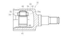
- the tripod type constant velocity universal joint 51 has three track grooves 53 extending in the axial direction at the three-way positions in the circumferential direction, and opposite side walls of the track grooves 53.
- An outer joint member 52 having a roller guide surface 54 formed thereon, a tripod member 60 having a trunnion journal 62 projecting radially from a circumferential trisection position of the trunnion body 61, and around each trunnion journal 62
- a roller 70 rotatably mounted via a plurality of needle rollers 72, and this roller 70 is accommodated in the track groove 53 of the outer joint member 52.
- the roller 70 has a spherical outer diameter surface 70a, and the spherical outer diameter surface 70a is guided by roller guide surfaces 54 formed on both side walls of the track groove 53 (see Patent Document 1).
- the roller 70 and the roller guide surface 54 are mutually connected as shown in FIG. 8b. It becomes an oblique relationship. Since the roller guide surface 54 of the track groove 53 is a part of a cylindrical surface parallel to the axis of the outer joint member 52, the roller 70 moves while being restrained by the roller guide surface 54 of the track groove 53. As a result, slip occurs between the roller guide surface 54 and the roller 70. This slip causes wear on the roller guide surface 54, and if this wear proceeds excessively, it causes vibrations and noise in the vehicle body. In order to reduce this wear, the spherical outer surface 70a of the roller 70 is ground and then barrel processed.
- the roller 70 is completed through many processing steps for a simple shape. Specifically, in FIG. 9a, a ring is formed by forging, and inner and outer diameter surfaces and chamfers are formed by turning in FIG. 9b. Thereafter, in FIG. 9c, quenching and tempering are performed by heat treatment. After the heat treatment, the outer diameter surface and the inner diameter surface are finished by grinding in FIG. 9d, and finally, tumbling is performed in FIG. 9e.
- the large number of processing steps increases the manufacturing cost and the time required for manufacturing.
- the present invention focuses on this problem.
- the present invention provides a tripod-type constant velocity universal joint and a method for manufacturing the same, which reduce the manufacturing cost and improve the productivity while maintaining the same function as a roller by a conventional processing method. For the purpose.
- the present invention includes an outer joint member in which a track groove extending in the axial direction is formed at a circumferential trisection position, and a radius from the trisection position in the circumferential direction.
- a tripod type constant velocity universal joint comprising a tripod member having a leg shaft protruding in a direction and a roller rotatably mounted on the leg shaft, the roller being accommodated in the track groove,
- the outer diameter surface of the roller is formed by a surface not subjected to grinding or cutting after heat treatment.
- the present invention about the manufacturing method includes an outer joint member in which a track groove extending in the axial direction is formed in a circumferentially divided position, and a leg shaft protruding in a radial direction from the circumferentially divided position.
- the manufacturing method of the tripod constant velocity universal joint including the tripod member having the roller and the roller rotatably mounted on the leg shaft, the roller being accommodated in the track groove.
- grinding refers to a processing method in which the surface of an object is removed little by little using a grindstone, and the object, media, compound, etc. are placed in the container and the container is rotated. Excludes barrel processing and tumbler processing that polish by applying vibration. Cutting refers to a processing method for scraping off an object using a cutting tool having a blade such as a cutting tool or an end mill.
- the outer diameter surface of the roller is a turning surface without a lead, so that the spherical outer diameter surface of the finished product finished by tumbling after the heat treatment is ground.
- a surface roughness equivalent to that of the conventional processed product can be obtained.
- the roundness of the outer diameter surface of the roller is preferably 10 ⁇ m or more and 40 ⁇ m or less, more preferably 10 ⁇ m or more and 30 ⁇ m or less. Thereby, the function equivalent to the roller by the conventional processing method is maintainable.
- the roundness of the outer diameter surface of the roller exceeds 40 ⁇ m, the life and durability are adversely affected due to slippage between the outer diameter surface of the roller and the roller guide surface.
- the heat treatment cost increases, which is not preferable.
- the tripod type constant velocity universal joint may be a single roller type in which a roller is rotatably mounted around a cylindrical outer peripheral surface of a trunnion journal as a leg shaft of a tripod member via a plurality of needle rollers.
- a lower cost tripod type constant velocity universal joint is realizable.
- the surface roughness of the outer diameter surface of the roller can be made equal to that of the conventional product, and the scale caused by the heat treatment can be removed.
- the tripod type constant velocity universal joint which aims to reduce the manufacturing cost and improve the productivity while maintaining the same function as the roller by the conventional processing method. And the manufacturing method thereof can be realized.
- FIG. 1 is a schematic diagram showing a manufacturing process of a roller of the tripod type constant velocity universal joint of FIGS. 1a and 1b, and shows a turning process.
- FIG. 1 is a schematic view showing a manufacturing process of a roller of the tripod type constant velocity universal joint of FIGS. 1a and 1b, and shows heat treatment.
- FIG.2 It is a schematic diagram showing a manufacturing process of a roller of the tripod type constant velocity universal joint of FIGS. 1a and 1b, and shows tumbling. It is a side view which shows the outline
- FIG. 4A and FIG. 4B show measurement results of roundness by the measurement method, and show a case of triangular heat treatment deformation.
- FIG. 4A and FIG. 4B show roundness measurement results obtained by the measurement method shown in FIG.
- the schematic diagram explaining the operating state of a roller shows the roller of this embodiment. It is a schematic diagram explaining the operation state of a roller, and shows the roller by the conventional processing method. It is a cross-sectional view showing a conventional tripod type constant velocity universal joint. It is a longitudinal cross-sectional view which shows the conventional tripod type constant velocity universal joint.
- mold constant velocity universal joint of FIG. It is a perspective view which shows the state of the roller of FIG. 8a, and a roller guide surface.
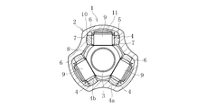
- FIG. 1a is a cross-sectional view of a tripod constant velocity universal joint according to an embodiment of the present invention
- FIG. 1b is a vertical cross-sectional view.
- a tripod type constant velocity universal joint 1 according to the present embodiment has an outer joint member 2, a tripod member 3 as an inner joint member, a spherical roller 4, and a needle roller 5 as a rolling element.
- the outer joint member 2 is in the shape of a hollow cup having three track grooves 6 extending in the axial direction at circumferentially equally divided positions on the inner periphery thereof.
- Roller guide surfaces 7 are formed on opposite side walls of each track groove 6.
- the roller guide surface 7 is formed of a part of a cylindrical surface, that is, a partial cylindrical surface.
- the spherical outer diameter surface 4a of the spherical roller 4 is guided to the roller guide surface 7 having such a shape.
- the tripod member 3 is composed of a trunnion body 8 and a trunnion journal 9 as a leg shaft, and the trunnion journal 9 is formed in a protruding manner in the radial direction from the circumferential trisection position of the trunnion body 8.
- Each trunnion journal 9 includes a cylindrical outer peripheral surface 10 and an annular retaining ring groove 11 formed near the shaft end.
- a spherical roller 4 is rotatably mounted around a cylindrical outer peripheral surface 10 of the trunnion journal 9 via a plurality of needle rollers 5.
- the cylindrical outer peripheral surface 10 of the trunnion journal 9 forms the inner raceway surface of the needle roller 5.
- the inner peripheral surface 4 b of the spherical roller 4 is cylindrical and forms the outer raceway surface of the needle roller 5.
- a retaining ring 13 is attached to a retaining ring groove 11 formed near the shaft end of the trunnion journal 9 via an outer washer 12.
- the needle roller 5 is restricted from moving in the axial direction of the trunnion journal 9 by the root step portion of the trunnion journal 9 and the outer washer 12.
- the outer washer 12 includes a disk portion 12 a extending in the radial direction of the trunnion journal 9 and a cylindrical portion 12 b extending in the axial direction of the trunnion journal 9.
- the cylindrical portion 12 b of the outer washer 12 has a smaller outer diameter than the inner peripheral surface 4 b of the spherical roller 4, and the outer end portion 12 c of the cylindrical portion 12 b viewed in the radial direction of the tripod member 3 is the inner periphery of the spherical roller 4. It has a larger diameter than the surface 4b. Therefore, the spherical roller 4 can move in the axial direction of the trunnion journal 9 and is prevented from falling off by the end 12c.
- the spherical roller 4 rotatably mounted on the trunnion journal 9 of the trunnion member 3 is guided rotatably on the roller guide surface 7 of the track groove 6 of the outer joint member 2.
- the spherical roller 4 and the roller guide surface 7 are in an oblique relationship with each other as in FIG. 8b described above. Since the roller guide surface 7 of the track groove 6 is a part of a cylindrical surface parallel to the axis of the outer joint member 2, the spherical roller 4 moves while being restrained by the roller guide surface 7 of the track groove 6. Become. As a result, slip occurs between the roller guide surface 7 and the roller 4.
- Angular contact has a contact angle and contacts at two points.
- the circular contact contacts at one point.
- the characteristic configuration of the tripod type constant velocity universal joint of the present embodiment is that the spherical outer diameter surface 4a of the spherical roller 4 is formed by a surface not subjected to grinding or cutting after heat treatment.
- the characteristic configuration of the embodiment of the manufacturing method of the tripod type constant velocity universal joint is that the manufacturing process of the roller does not include the process of grinding the spherical outer diameter surface 4a of the spherical roller 4, and the total shape tool is used.
- the present invention is provided with a turning process and a tumbling process.
- FIG. 2a a ring-shaped shaped material 4 (1) is formed by forging, and inner and outer diameter surfaces, end faces and chamfers are formed by turning in FIG. 2b to obtain a turned product 4 (2). Thereafter, in FIG. 2c, quenching and tempering are performed by heat treatment to obtain a heat-treated product 4 (3). After the heat treatment, the finished product 4 is obtained by performing the tumbling process in FIG. 2d without finishing by the grinding process employed in the conventional processing method.
- the material of the spherical roller 4 is usually high carbon chrome bearing steel.
- the heat treatment shown in FIG. 2c is subjected to continuous quenching and has a hardness of about HRC 58 to 61.
- Tumble processing is usually performed for the purpose of deburring, descaling, etc., and is a polishing method in which an object and a compound are placed in a container, the container is rotated, and polishing is performed by the mutual action of the objects.
- the surface roughness of the outer diameter surface of the spherical roller 4 can be made equal to that of the conventional product, and the scale caused by the heat treatment can be removed.
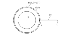
- FIGS. 3a and 3b show the turning process of the spherical outer diameter surface 4 (2) 1 with a total tool.
- 3a is a side view
- FIG. 3b is a plan view.
- the inner and outer diameter surfaces, end surfaces, and the like of the spherical roller shaped member 4 (1) shown in FIG. 2a are turned to chuck the cylindrical semi-finished product 4 (2) ′ (not shown) to obtain the semi-finished product 4 (2 ) ′ ′ Is sent in a direction perpendicular to the axis X to turn the spherical outer diameter surface 4 (2) 1.
- the spherical outer diameter surface 4 (2) 1 is formed with a turning surface with no lead. Since the spherical roller 4 of the tripod type constant velocity universal joint 1 of this embodiment does not perform grinding after heat treatment, the dimension of the turning surface of the spherical outer diameter surface 4 (2) 1 does not provide a grinding allowance. Finished product dimensions.
- the following unexpected advantages were found by turning the spherical outer diameter surface 4 (2) 1 with the above-described general tool 20.
- the turned product 4 (2) is subjected to the heat treatment of FIG. 2c and the tumbling process of FIG. 2d. It was found that the surface roughness of the spherical outer diameter surface 4a of the finished product 4 finished by tumbling can be equal to that of the conventional product subjected to grinding. Thus, it was verified that the surface roughness of the spherical outer diameter surface 4a by the synergistic action of the turning of the spherical outer diameter surface 4 (2) 1 by the total tool 20 and the tumbling as the finishing process was good. This was the key to analyzing the processing process and to determine the possibility of simplification.
- the verification result of the surface roughness of the spherical outer diameter surface 4a described above became a motivation for trying to verify the degree of influence of heat treatment deformation on the joint function as the next step. Since the spherical roller 4 applied to this embodiment does not grind after heat processing, the deformation
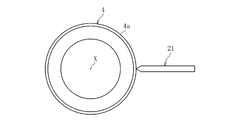
- FIGS. 4a, 4b, 5a and 5b show an outline of a method for measuring roundness
- FIG. 4a is a plan view
- FIG. 4b is a side view.
- the roundness measuring machine used was TALYROND 265 manufactured by Taylor Hobson Co., Ltd., and the spindle rotation speed was measured at 6 min ⁇ 1 .
- the measurement terminal 21 was measured in contact with the center of the spherical outer diameter surface 4 a of the spherical roller 4.
- FIGS. 5a and 5b Representative examples of the above measurement results are shown in FIGS. 5a and 5b.
- FIG. 5a illustrates a heat treatment variant having a triangular shape
- FIG. 5b illustrates a heat treatment variant having a bowl shape having convex portions at two locations. Both of them have a roundness of 20 ⁇ m.
- the spherical roller 4 of the example that was not subjected to grinding was incorporated into the tripod type constant velocity universal joint 1 to evaluate the joint characteristics.
- spherical rollers 4 having various roundness such as a triangular shape (see FIG. 5a) or a saddle shape (see FIG. 5b) having a roundness of 10 to 30 ⁇ m in which heat treatment deformation remained were prepared.
- Conventional products have been ground with a roundness of less than 5 ⁇ m.
- Table 1 The evaluation results are shown in Table 1.
- the display about the evaluation result of the joint characteristic in Table 1 is as follows. In Table 1, all the above-mentioned various spherical rollers 4 have the same result, and are therefore described collectively. A: Excellent, B: No problem in practical use
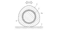
- FIG. 6A is a schematic diagram showing an operating state of a spherical roller applied to this embodiment
- FIG. 6B is a schematic diagram showing an operating state of a conventional spherical roller.
- the spherical roller in FIG. 6a illustrates a triangular heat treatment deformation, and the deformation amount is exaggerated for easy understanding.
- the spherical outer surface 70a of the conventional ground spherical roller 70 shown in FIG. 6b has a roundness of 4 ⁇ m or less and an outer diameter due to phase. There is little variation. For this reason, during the swinging motion indicated by the white arrow, the spherical roller 70 continues to receive a load within a certain range of the spherical outer diameter surface 70a, so that damage is likely to proceed, which may be disadvantageous in life. It supplements about said rocking motion.
- the tripod type constant velocity universal joint rotates at an operating angle ⁇
- the tripod type constant velocity universal joint repeats a movement like a wiper that inclines from the inclined state of the trunnion journal 62 shown in FIG. This movement is called rocking movement.
- rocking movement The same applies to the following embodiment.
- the spherical outer diameter surface 4a of the spherical roller 4 applied to the embodiment shown in FIG. 6a in which the grinding process is not performed after the heat treatment shown in FIG. 6a is larger than the conventional product described above, and the roundness is as large as 10 to 30 ⁇ m.
- a difference occurs in the outer diameter. Due to the outer diameter difference due to this phase, the spherical roller 4 of this embodiment has a difference in rolling resistance between the spherical roller 4 and the roller guide surface 7 due to the phase, and the movement changes during the swinging motion (open arrow). As a result, the spherical roller 4 is moved little by little, and the spherical roller 4 moves using the entire outer periphery of the spherical outer diameter surface 4a.
- the roller guide surface 7 Since the shape of the contacting roller is not constant and unstable, when the spherical roller 4 contacts the roller guide surface 7 on the opposite side, the spherical roller 4 is easy to rotate and moves using the entire outer periphery of the spherical outer diameter surface 4a. It is conceivable that the contact area is distributed and leveled, which is advantageous for the service life.
- the outer circumference of the spherical roller 4 of the present embodiment in which grinding is not performed after heat treatment is longer than that of the conventional ground roller 70. For this reason, the spherical roller 4 of the present embodiment has a smaller rotation angle of the roller with respect to the same slide amount. If the rotation angle is small, the amount of rolling of the needle rollers 5 on the trunnion journal 9 is reduced, and the rolling resistance is reduced.
- the spherical roller 4 of the present embodiment is combined with the conventional spherical roller 70 subjected to grinding by combining the turning surface without lead and tumbling. Since equivalent surface roughness can be obtained, it is conceivable that wear resistance and durability can be maintained.
- the characteristic configuration of the tripod type constant velocity universal joint according to the present embodiment is such that the spherical outer diameter surface 4a of the spherical roller 4 is formed by a surface not subjected to grinding or cutting after heat treatment. There is in being.
- the characteristic configuration of the embodiment of the manufacturing method of the tripod type constant velocity universal joint is that the manufacturing process of the roller does not include the process of grinding the spherical outer diameter surface 4a of the spherical roller 4, and the total shape tool is used.
- the present invention is provided with a turning process and a tumbling process. Accordingly, it is possible to realize a tripod constant velocity universal joint and a method for manufacturing the same, which can reduce the manufacturing cost and improve the productivity while maintaining a function equivalent to that of a roller by a conventional processing method.
- the tripod type constant velocity universal joint of this embodiment is of a single roller type in which a roller is rotatably mounted via a plurality of needle rollers around a cylindrical outer peripheral surface of a trunnion journal as a leg shaft of a tripod member.
- the present invention is not limited to this, and the present invention can be applied to a double roller type tripod type constant velocity universal joint in which a roller cassette including an inner ring, needle rollers, and rollers is mounted on a leg shaft of a tripod member.
Landscapes
- Engineering & Computer Science (AREA)
- Chemical & Material Sciences (AREA)
- General Engineering & Computer Science (AREA)
- Mechanical Engineering (AREA)
- Thermal Sciences (AREA)
- Crystallography & Structural Chemistry (AREA)
- Materials Engineering (AREA)
- Metallurgy (AREA)
- Organic Chemistry (AREA)
- Physics & Mathematics (AREA)
- Manufacturing & Machinery (AREA)
- Rolling Contact Bearings (AREA)
- Ocean & Marine Engineering (AREA)
Priority Applications (3)
| Application Number | Priority Date | Filing Date | Title |
|---|---|---|---|
| EP15827592.5A EP3176453B1 (en) | 2014-07-30 | 2015-06-30 | Tripod constant velocity universal joint and method for manufacturing same |
| CN201580038588.2A CN106536955B (zh) | 2014-07-30 | 2015-06-30 | 三球销型等速万向联轴器及其制造方法 |
| US15/326,704 US10655677B2 (en) | 2014-07-30 | 2015-06-30 | Tripod constant velocity universal joint and method for manufacturing same |
Applications Claiming Priority (2)
| Application Number | Priority Date | Filing Date | Title |
|---|---|---|---|
| JP2014154978A JP6382014B2 (ja) | 2014-07-30 | 2014-07-30 | トリポード型等速自在継手およびその製造方法 |
| JP2014-154978 | 2014-07-30 |
Publications (1)
| Publication Number | Publication Date |
|---|---|
| WO2016017345A1 true WO2016017345A1 (ja) | 2016-02-04 |
Family
ID=55217249
Family Applications (1)
| Application Number | Title | Priority Date | Filing Date |
|---|---|---|---|
| PCT/JP2015/068807 Ceased WO2016017345A1 (ja) | 2014-07-30 | 2015-06-30 | トリポード型等速自在継手およびその製造方法 |
Country Status (5)
| Country | Link |
|---|---|
| US (1) | US10655677B2 (https=) |
| EP (1) | EP3176453B1 (https=) |
| JP (1) | JP6382014B2 (https=) |
| CN (1) | CN106536955B (https=) |
| WO (1) | WO2016017345A1 (https=) |
Cited By (1)
| Publication number | Priority date | Publication date | Assignee | Title |
|---|---|---|---|---|
| JP2021055794A (ja) * | 2019-10-01 | 2021-04-08 | Ntn株式会社 | 機械加工品 |
Citations (6)
| Publication number | Priority date | Publication date | Assignee | Title |
|---|---|---|---|---|
| JPH06249317A (ja) * | 1993-02-26 | 1994-09-06 | Ntn Corp | ボールねじのねじ溝加工方法 |
| JP2000081050A (ja) * | 1998-09-08 | 2000-03-21 | Nippon Seiko Kk | トリポード型等速ジョイント用円筒ローラとその製造方法 |
| JP2001054912A (ja) * | 1999-08-18 | 2001-02-27 | Ricoh Co Ltd | 回転体の成形品並びにその成形方法及び成形金型 |
| JP2001300675A (ja) * | 2000-02-18 | 2001-10-30 | Nsk Ltd | ねじ転造ダイス及びその製造方法 |
| JP2002235753A (ja) * | 2001-02-09 | 2002-08-23 | Ntn Corp | シェル型ころ軸受 |
| JP2007040503A (ja) * | 2005-08-05 | 2007-02-15 | Ntn Corp | 鍔付ころ軸受 |
Family Cites Families (17)
| Publication number | Priority date | Publication date | Assignee | Title |
|---|---|---|---|---|
| JPS5333084U (https=) * | 1976-08-28 | 1978-03-23 | ||
| JPS5333084A (en) | 1976-09-09 | 1978-03-28 | Agency Of Ind Science & Technol | Silicon solar battery |
| JP2635083B2 (ja) * | 1988-03-02 | 1997-07-30 | 新日本工機株式会社 | 旋盤および旋盤による加工方法 |
| CN1178571A (zh) * | 1996-02-05 | 1998-04-08 | 株式会社Ntn | 三通型等速万向联轴节 |
| US6390924B1 (en) * | 1999-01-12 | 2002-05-21 | Ntn Corporation | Power transmission shaft and constant velocity joint |
| JP2000256694A (ja) | 1999-03-11 | 2000-09-19 | Ntn Corp | トリポード型等速自在継手および当該継手用グリース |
| JP3947342B2 (ja) | 2000-05-22 | 2007-07-18 | Ntn株式会社 | トリポード型等速自在継手 |
| JP2002213477A (ja) * | 2001-01-16 | 2002-07-31 | Ntn Corp | トリポード型等速自在継手 |
| US6708544B2 (en) | 2001-02-16 | 2004-03-23 | Nsk Ltd. | Thread rolling die and process for the production thereof |
| JP2004100754A (ja) * | 2002-09-06 | 2004-04-02 | Nsk Ltd | 軸受装置の外輪内面の滑面仕上処理方法および該処理方法を施した軸受装置 |
| JP2004360830A (ja) * | 2003-06-05 | 2004-12-24 | Ntn Corp | 等速自在継手およびその製造方法 |
| JP4361351B2 (ja) * | 2003-11-14 | 2009-11-11 | Ntn株式会社 | トリポード型等速自在継手 |
| JP4541203B2 (ja) * | 2005-03-24 | 2010-09-08 | Ntn株式会社 | トリポード型等速自在継手 |
| WO2007148487A1 (ja) | 2006-06-23 | 2007-12-27 | Ntn Corporation | 等速自在継手及びこれを用いたドライブシャフト、駆動車輪用軸受ユニット |
| JP2008275095A (ja) * | 2007-05-01 | 2008-11-13 | Ntn Corp | ボールねじおよびその製造方法 |
| KR101405191B1 (ko) * | 2012-11-15 | 2014-06-10 | 기아자동차 주식회사 | 등속 조인트 |
| CN103331456A (zh) * | 2013-06-26 | 2013-10-02 | 上海斐赛轴承科技有限公司 | 套圈整体精密硬车成型的滚动轴承的加工方法 |
-
2014
- 2014-07-30 JP JP2014154978A patent/JP6382014B2/ja active Active
-
2015
- 2015-06-30 US US15/326,704 patent/US10655677B2/en not_active Expired - Fee Related
- 2015-06-30 CN CN201580038588.2A patent/CN106536955B/zh not_active Expired - Fee Related
- 2015-06-30 EP EP15827592.5A patent/EP3176453B1/en active Active
- 2015-06-30 WO PCT/JP2015/068807 patent/WO2016017345A1/ja not_active Ceased
Patent Citations (6)
| Publication number | Priority date | Publication date | Assignee | Title |
|---|---|---|---|---|
| JPH06249317A (ja) * | 1993-02-26 | 1994-09-06 | Ntn Corp | ボールねじのねじ溝加工方法 |
| JP2000081050A (ja) * | 1998-09-08 | 2000-03-21 | Nippon Seiko Kk | トリポード型等速ジョイント用円筒ローラとその製造方法 |
| JP2001054912A (ja) * | 1999-08-18 | 2001-02-27 | Ricoh Co Ltd | 回転体の成形品並びにその成形方法及び成形金型 |
| JP2001300675A (ja) * | 2000-02-18 | 2001-10-30 | Nsk Ltd | ねじ転造ダイス及びその製造方法 |
| JP2002235753A (ja) * | 2001-02-09 | 2002-08-23 | Ntn Corp | シェル型ころ軸受 |
| JP2007040503A (ja) * | 2005-08-05 | 2007-02-15 | Ntn Corp | 鍔付ころ軸受 |
Cited By (1)
| Publication number | Priority date | Publication date | Assignee | Title |
|---|---|---|---|---|
| JP2021055794A (ja) * | 2019-10-01 | 2021-04-08 | Ntn株式会社 | 機械加工品 |
Also Published As
| Publication number | Publication date |
|---|---|
| EP3176453B1 (en) | 2019-09-04 |
| US20180335076A1 (en) | 2018-11-22 |
| JP6382014B2 (ja) | 2018-08-29 |
| CN106536955A (zh) | 2017-03-22 |
| CN106536955B (zh) | 2022-07-22 |
| US10655677B2 (en) | 2020-05-19 |
| EP3176453A4 (en) | 2018-04-25 |
| EP3176453A1 (en) | 2017-06-07 |
| JP2016031132A (ja) | 2016-03-07 |
Similar Documents
| Publication | Publication Date | Title |
|---|---|---|
| JP2009014126A (ja) | ころ軸受 | |
| EP2141375A1 (en) | Trunnion, toripod-type constant-velocity universal joint using the trunnion and method of producing the same | |
| JP2005106234A (ja) | 円錐ころ軸受と円錐ころ加工方法 | |
| JP2017150597A (ja) | 転がり軸受、転動装置および転動装置の製造方法 | |
| JP2019042864A (ja) | リング状部材の研削装置および研削方法、並びに、ラジアル軸受の製造方法 | |
| JP2019211084A (ja) | ハブユニット軸受およびその製造方法、並びに、自動車およびその製造方法 | |
| WO2016147827A1 (ja) | トリポード型等速自在継手 | |
| JP6382014B2 (ja) | トリポード型等速自在継手およびその製造方法 | |
| JP2005054879A (ja) | 等速自在継手 | |
| CN105899831B (zh) | 改进的扭矩传递接头和接头部件、制造方法以及检查方法 | |
| JP5747723B2 (ja) | トロイダル型無段変速機のトラニオンおよびその加工方法 | |
| CN220227581U (zh) | 滑动式等速万向联轴器 | |
| JP2016156428A (ja) | 転動体及び等速ジョイント用転動体 | |
| KR20170138485A (ko) | 롤링 베어링을 위한 회전체의 제조 방법 | |
| JP5323572B2 (ja) | トリポード型等速自在継手およびその製造方法 | |
| JP4064440B1 (ja) | 車輪軸受装置の製造方法 | |
| WO2023068018A1 (ja) | トリポード型等速自在継手 | |
| JP2008232221A (ja) | スラスト針状ころ軸受 | |
| JP2011185346A (ja) | 等速自在継手 | |
| JP3851094B2 (ja) | トロイダル型無段変速機及びこれに用いるローラの加工方法 | |
| JP7517121B2 (ja) | トロイダル型無段変速機用の支持軸の製造方法 | |
| KR20160062144A (ko) | 원추 롤러의 제조 방법 및 원추 롤러 베어링 | |
| JP2014016007A (ja) | トリポード型等速ジョイントおよびその製造方法 | |
| JP2019190586A (ja) | 軌道部材の製造方法 | |
| JP2017133685A (ja) | 転がり軸受、転動装置および転動装置の製造方法 |
Legal Events
| Date | Code | Title | Description |
|---|---|---|---|
| 121 | Ep: the epo has been informed by wipo that ep was designated in this application |
Ref document number: 15827592 Country of ref document: EP Kind code of ref document: A1 |
|
| WWE | Wipo information: entry into national phase |
Ref document number: 15326704 Country of ref document: US |
|
| NENP | Non-entry into the national phase |
Ref country code: DE |
|
| REEP | Request for entry into the european phase |
Ref document number: 2015827592 Country of ref document: EP |
|
| WWE | Wipo information: entry into national phase |
Ref document number: 2015827592 Country of ref document: EP |