WO2015198961A1 - 電動機の固定子及び回転電機の冷却構造 - Google Patents
電動機の固定子及び回転電機の冷却構造 Download PDFInfo
- Publication number
- WO2015198961A1 WO2015198961A1 PCT/JP2015/067612 JP2015067612W WO2015198961A1 WO 2015198961 A1 WO2015198961 A1 WO 2015198961A1 JP 2015067612 W JP2015067612 W JP 2015067612W WO 2015198961 A1 WO2015198961 A1 WO 2015198961A1
- Authority
- WO
- WIPO (PCT)
- Prior art keywords
- stator
- winding
- teeth
- insulating member
- water jacket
- Prior art date
Links
Images


Classifications
-
- H—ELECTRICITY
- H02—GENERATION; CONVERSION OR DISTRIBUTION OF ELECTRIC POWER
- H02K—DYNAMO-ELECTRIC MACHINES
- H02K21/00—Synchronous motors having permanent magnets; Synchronous generators having permanent magnets
- H02K21/12—Synchronous motors having permanent magnets; Synchronous generators having permanent magnets with stationary armatures and rotating magnets
- H02K21/14—Synchronous motors having permanent magnets; Synchronous generators having permanent magnets with stationary armatures and rotating magnets with magnets rotating within the armatures
- H02K21/16—Synchronous motors having permanent magnets; Synchronous generators having permanent magnets with stationary armatures and rotating magnets with magnets rotating within the armatures having annular armature cores with salient poles
-
- H—ELECTRICITY
- H02—GENERATION; CONVERSION OR DISTRIBUTION OF ELECTRIC POWER
- H02K—DYNAMO-ELECTRIC MACHINES
- H02K3/00—Details of windings
- H02K3/32—Windings characterised by the shape, form or construction of the insulation
- H02K3/34—Windings characterised by the shape, form or construction of the insulation between conductors or between conductor and core, e.g. slot insulation
-
- H—ELECTRICITY
- H02—GENERATION; CONVERSION OR DISTRIBUTION OF ELECTRIC POWER
- H02K—DYNAMO-ELECTRIC MACHINES
- H02K1/00—Details of the magnetic circuit
- H02K1/06—Details of the magnetic circuit characterised by the shape, form or construction
- H02K1/12—Stationary parts of the magnetic circuit
- H02K1/14—Stator cores with salient poles
- H02K1/146—Stator cores with salient poles consisting of a generally annular yoke with salient poles
-
- H—ELECTRICITY
- H02—GENERATION; CONVERSION OR DISTRIBUTION OF ELECTRIC POWER
- H02K—DYNAMO-ELECTRIC MACHINES
- H02K3/00—Details of windings
- H02K3/04—Windings characterised by the conductor shape, form or construction, e.g. with bar conductors
- H02K3/18—Windings for salient poles
-
- H—ELECTRICITY
- H02—GENERATION; CONVERSION OR DISTRIBUTION OF ELECTRIC POWER
- H02K—DYNAMO-ELECTRIC MACHINES
- H02K3/00—Details of windings
- H02K3/32—Windings characterised by the shape, form or construction of the insulation
- H02K3/34—Windings characterised by the shape, form or construction of the insulation between conductors or between conductor and core, e.g. slot insulation
- H02K3/345—Windings characterised by the shape, form or construction of the insulation between conductors or between conductor and core, e.g. slot insulation between conductor and core, e.g. slot insulation
-
- H—ELECTRICITY
- H02—GENERATION; CONVERSION OR DISTRIBUTION OF ELECTRIC POWER
- H02K—DYNAMO-ELECTRIC MACHINES
- H02K5/00—Casings; Enclosures; Supports
- H02K5/04—Casings or enclosures characterised by the shape, form or construction thereof
- H02K5/20—Casings or enclosures characterised by the shape, form or construction thereof with channels or ducts for flow of cooling medium
- H02K5/203—Casings or enclosures characterised by the shape, form or construction thereof with channels or ducts for flow of cooling medium specially adapted for liquids, e.g. cooling jackets
-
- H—ELECTRICITY
- H02—GENERATION; CONVERSION OR DISTRIBUTION OF ELECTRIC POWER
- H02K—DYNAMO-ELECTRIC MACHINES
- H02K9/00—Arrangements for cooling or ventilating
- H02K9/19—Arrangements for cooling or ventilating for machines with closed casing and closed-circuit cooling using a liquid cooling medium, e.g. oil
- H02K9/197—Arrangements for cooling or ventilating for machines with closed casing and closed-circuit cooling using a liquid cooling medium, e.g. oil in which the rotor or stator space is fluid-tight, e.g. to provide for different cooling media for rotor and stator
-
- H—ELECTRICITY
- H02—GENERATION; CONVERSION OR DISTRIBUTION OF ELECTRIC POWER
- H02K—DYNAMO-ELECTRIC MACHINES
- H02K2203/00—Specific aspects not provided for in the other groups of this subclass relating to the windings
- H02K2203/12—Machines characterised by the bobbins for supporting the windings
Definitions
- the present invention relates to a motor stator applied to industrial equipment as a single drive source or as a hybrid drive source together with an engine, and a rotating electrical machine cooling structure applied to automobiles and industrial equipment.
- Electric motors including various IPM motors and generators applied to industrial equipment such as automobiles, agricultural machinery, construction machinery, and utility vehicles are mounted on devices as series hybrid type or parallel hybrid type driving sources.
- an electric motor for example, an embedded permanent magnet synchronous motor is used.
- teeth are protruded from a split yoke to form a split stator, and a large number of stators are annularly arranged, and a large number of teeth protrude from the inner periphery of the annular yoke.
- a yoke integrated type There is a yoke integrated type.
- a stator piece annular coupling type stator is disclosed in Patent Document 1.
- the stator disclosed in Patent Document 1 is a stator that annularly connects stator pieces each having a winding wound around each pole tooth of an insulated split core.
- the stator includes a slot insulating plate that insulates the slot opening of the split iron core, and an elastic insulator.
- the insulator is interposed between the slot insulating plate and the winding.
- the electric motor of Patent Literature 2 includes a stator body having a stator body provided in a motor housing, a stator coil wound around the stator body, and a rotor rotatably inserted in the stator. Resin is provided in the gap between the end surface of the stator main body and the inner wall surface of the motor housing.
- the motor housing has a double structure consisting of an outer tube portion and an inner tube portion to form a water jacket, and the cooling medium passing through a gap (jacket passage) inside the water jacket absorbs the heat of the stator coil and the stator. It is configured.
- the stator of the electric motor has the coil concentrated or distributedly wound around the teeth protruding from the yoke.
- direct cooling using an automatic transmission fluid (ATF) liquid cooling using a water jacket as an external case, etc. It has been implemented.
- ATF cooling the contact area between the coil and the refrigerant is small. Therefore, the amount of heat transfer is small, or cooling near the coil is difficult.
- water jacket cooling of the outer case there is an air layer between the stator and the outer case, and the thermal resistance is large. Further, since the distance to the coil is long, the heat dissipation efficiency is low.
- Patent Document 3 discloses a technique in which an electromagnetic coil wound around an iron core is molded with a mold resin, and a high thermal conductivity of the mold resin is utilized. Further, in Patent Document 4, a refrigerant supply port is disposed apart from the coil in the axial direction of the stator, and the refrigerant is supplied from the refrigerant supply port to the axial end surface and the circumferential end surface of the coil. Thus, a technique is disclosed in which the cooling efficiency is improved by bringing them into contact with each other.
- JP 2006-141173 A Japanese Patent Laid-Open No. 10-290543 WO2012 / 101976A1 specification JP 2014-096876 A
- Patent Document 1 can be expected to reduce deterioration over time by an insulator.
- the contact area between the insulator and the teeth (divided iron core) and between the insulator and the winding becomes small.
- the disclosed technique of Patent Document 2 can use a heat transfer path from the stator outer periphery to the water jacket, and a heat transfer path from the stator coil and the stator surface to the water jacket via the resin. Therefore, it is possible to increase the cooling efficiency.
- the jacket passage serving as the cooling medium flow passage is formed in the motor housing, the motor housing itself is unlikely to be a high-strength member. Further, since the motor housing having the jacket passage and the stator are coupled together by shrinkage, the thermal resistance may increase and the cooling capacity may be reduced.
- Patent Document 3 can efficiently conduct heat conduction from the electromagnetic coil to the mold resin.
- the outer case must also be formed of a mold resin, it is difficult to dissipate heat from the mold resin to the outside if it is placed in a metal outer case.
- the technique disclosed in Patent Document 4 can directly cool the peripheral surface of the coil.
- the refrigerant has a short time of contact with the coil, it is difficult to increase the cooling efficiency.
- An object of the present invention is to provide a stator for an electric motor and a cooling structure for a rotating electric machine that can solve the problems of the prior art.
- an unevenness is formed on the surface of the tooth and the inner surface of the insulating member surrounding the tooth, and the unevenness on the surface of the tooth and the unevenness on the inner surface of the insulating member are fitted and fitted together, whereby the tooth and the insulating member. It is an object of the present invention to provide a stator for an electric motor capable of increasing the amount of heat transfer between the motor and the heat resistance and decreasing the thermal resistance.
- the present invention provides a heat conductor that is integrated with the winding and the stator on the inner peripheral surface of the water jacket, and by mounting the water jacket in a separate motor housing,
- An object of the present invention is to provide a cooling structure for a rotating electrical machine that can ensure strength and improve cooling efficiency.
- the present invention provides a cooling structure for a rotating electrical machine that can efficiently cool a winding by forming a passage for refrigerant inside a heat conductor made of high thermal conductivity resin that covers the winding of the tooth. The purpose is to do.
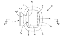
- the stator 1 of the electric motor includes a yoke 2, a plurality of teeth 3 arranged in the circumferential direction on the inner peripheral side of the yoke 2, a winding 5 wound around the teeth 3, a tooth 3 and a winding 5. And an insulating member 4 made of an elastic resin interposed between them, and at least the circumferential surface A of the circumferential surface A and the axial surface B of the teeth 3 is formed with irregularities 3a. Concavities and convexities 4a are formed on the inner surface so as to fit into the concavities and convexities 3a.
- the insulating member 4 has an outer surface 4 b that surrounds the tooth 3 and is located outside the circumferential surface A and the axial surface B of the tooth 3, and the outer surface 4 b is medium-high in the winding direction of the winding 5. It is formed in an arc shape.
- the winding 5 has a circular cross section, the outer surface 4b has a mounting portion 4c into which the winding 5 is fitted, and a plurality of mounting portions 4c are formed in the radial direction of the teeth 3.
- the rotating electrical machine cooling structure includes a water jacket 12 in which a jacket passage 12a for allowing a refrigerant to pass is formed, an annular stator 14 provided on the inner periphery of the water jacket 12, and a winding around the stator 14.
- the heat conductor 15 has a high thermal conductivity.
- the water jacket 12 is formed of a high thermal conductivity material and is mounted in the motor housing 16.
- the water jacket 12 is a resin and is molded so as to cover the winding 13 and the stator 14.
- the water jacket 12 is formed of an aluminum alloy
- the motor housing 16 is formed of an iron-based casting
- the heat conductor 15 is formed in the water jacket 12 before the water jacket 12 is mounted in the motor housing 16.
- the peripheral surface 12b is molded so as to cover the winding 13 and the stator 14.
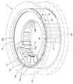
- the water jacket 12 has a cylindrical shape, and the jacket passage 12a is formed in a zigzag shape in the circumferential direction with a width extending between both ends in the axial direction.
- the heat conductor 15 is formed such that the width of the stator 14 in the axial direction is wider on the outer side than the inner side, and the outer side of the heat conductor 15 is substantially the entire width in the axial direction of the water jacket 12. It corresponds to.
- a refrigerant passage 18 is formed inside the heat conductor 15, and the refrigerant passage 18 overlaps the stator 14 and the winding 13.
- the cooling structure of the rotating electric machine has an annular yoke 32, a tooth 33 protruding from the yoke 32, a winding 35 wound around the tooth 33, and a fixed structure having the yoke 32, the tooth 33 and the winding 35.
- an insulating member 34 made of an elastic resin is provided between the teeth 33 and the windings 35, and the windings 35 are concentratedly wound around the teeth 33 via the insulating members 34.
- Reference numeral 38 is disposed so as to overlap the winding 35. 12thly, the refrigerant
- the amount of heat transfer between the teeth and the insulating member can be increased and the thermal resistance can be decreased. That is, unevenness 3a is formed on at least the circumferential surface A of the circumferential surface A and the axial surface B of the tooth 3, and the unevenness 4a is formed on the inner surface of the insulating member 4 so as to fit the unevenness 3a.
- the inner surface of the insulating member 4 can be in close contact with the circumferential surface A of the tooth 3 with a large area, the air layer is reduced, the amount of heat transfer between them can be increased, and the thermal resistance can be reduced.
- the outer surface 4 b of the insulating member 4 is formed in a middle-high arc shape in the winding direction of the winding 5. Therefore, the air layer between the outer surface 4b of the insulating member 4 and the winding 5 is reduced, the amount of heat transfer between the two can be increased, and the thermal resistance can be reduced.
- the winding 5 has a circular cross section, and the outer surface 4b has a spiral concavo-convex portion (a spiral mounting portion including a concave portion and a convex portion) 4c into which the winding 5 is fitted, and the mounting portion 4c is the diameter of the tooth 3. A large number are arranged in the direction.
- the outer surface 4b of the insulating member 4 and the winding 5 can be in close contact with a large area. Thereby, the air layer between the outer surface 4b of the insulating member 4 and the coil
- the insulating member 4 has a split shape. One of the split members 4 and the other insulating member 4 are opposed to each other, and the opposing one insulating member 4 and the other insulating member 4 are the teeth 3. The circumferential surface A and the axial surface B are surrounded. Therefore, it is possible to manufacture and attach the insulating member 4 very easily.
- the cooling structure for a rotating electrical machine of the present invention it is possible to ensure the strength of the water jacket of the rotating electrical machine and improve the cooling efficiency.
- a water jacket 12 in which a jacket passage 12a through which a refrigerant passes is formed, an annular stator 14 provided on the inner periphery of the water jacket 12, a winding 13 wound around the stator 14, a water jacket 12 includes a heat conductor 15 integrated with the inner peripheral surface 12b of the twelve, a water jacket 12 and a separate motor housing 16, and the heat conductor 15 is a resin having high thermal conductivity,
- the water jacket 12 is formed of a material having high thermal conductivity and is mounted in the motor housing 16 so as to cover the stator 14. Therefore, the reinforcing strength of the water jacket 12 can be secured while improving the cooling efficiency.
- the water jacket 12 is formed of an aluminum alloy
- the motor housing 16 is formed of an iron-based casting
- the heat conductor 15 is formed on the inner peripheral surface of the water jacket 12 before the water jacket 12 is mounted in the motor housing 16.
- 12 b is molded so as to cover the winding 13 and the stator 14. That is, the water jacket 12 is mounted on a high strength iron-based cast motor housing 16 while being formed of an aluminum alloy having a high thermal conductivity. Therefore, the strength of the water jacket 12 can be more reliably ensured while improving the cooling efficiency.
- the water jacket 12 has a cylindrical shape, and the jacket passage 12a is formed in a zigzag shape in the circumferential direction with a width extending between both ends in the axial direction. Therefore, the circulating refrigerant can cool the water jacket 12 efficiently.
- the heat conductor 15 is formed such that the width of the stator 14 in the axial direction is wider on the outer side than the inner side, and the outer side of the heat conductor 15 corresponds to substantially the entire width of the water jacket 12 in the axial direction. is doing. Therefore, heat conduction from the heat conductor 15 to the water jacket 12 can be efficiently and effectively performed with a small amount of material.
- a refrigerant passage 18 is formed inside the heat conductor 15, and the refrigerant passage 18 overlaps the stator 14 and the winding 13. Therefore, the heat conductor 15 itself can be efficiently cooled near the stator 14 and the winding 13. Moreover, according to the cooling structure for a rotating electric machine of the present invention, the winding can be efficiently cooled. That is, an annular yoke 32, a tooth 33 protruding from the yoke 32, a winding 35 wound around the tooth 33, a stator 31 having the yoke 32, the teeth 33 and the winding 35, and a resin having a high thermal conductivity.
- the heat conductor 37 is molded on both side surfaces in the axial direction of the stator 31 while filling the space between the windings 35, and inside the heat conductor 37, A refrigerant flow passage 38 is formed. For this reason, the heat conductor 37 having a large volume can remove heat from the winding 35 with little resistance, and the heat can be efficiently cooled by the refrigerant passing through the refrigerant passage 38 in the heat conductor 37.
- the insulating member 34 made of elastic resin is provided between the teeth 33 and the windings 35.
- the windings 35 are concentratedly wound around the teeth 33 via the insulating members 34. It is arranged so as to overlap with the winding 35. Therefore, the heat conductor 37 can be molded by filling a resin having a high thermal conductivity between the windings 35, and heat can be transferred from the entire circumference of the winding 35 to the heat conductor 37. It is possible to efficiently cool with the refrigerant in the refrigerant passage 38 arranged in an overlapping manner.
- the refrigerant passage 38 is formed on at least one side surface in the axial direction of the stator 31 in an annular shape, a spiral shape, a mesh shape, or a circumferential zigzag shape when viewed in the axial direction. Therefore, the side surface in the axial direction of the stator 31 has a wide area, and the heat conductor 37 can be cooled in the wide area portion, and the cooling efficiency can be increased.
- FIG. 2 is a sectional view taken along line XX in FIG.
- FIG. 2 is a sectional view taken along line YY in FIG.
- FIG. 7 is a sectional view taken along line ZZ in FIG. 6.
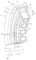
- FIG. 1 is a perspective explanatory view showing a first embodiment of a rotating electrical machine cooling structure of the present invention. It is a partial cross section front view which shows 1st Embodiment of the cooling structure of the rotary electric machine of this invention. It is a hierarchy fracture side explanatory view showing a 1st embodiment of a cooling structure of a rotating electrical machine of the present invention. It is a perspective explanatory view showing a jacket passage of a water jacket.
- FIG. 16 is a sectional view taken along line XX in FIG. 15.
- FIG. 16 is a cross-sectional view taken along line YY of FIG.
- FIG. 16 is a view taken in the direction of arrow Z in FIG. 15.
- FIG. 1 to 5 show a first embodiment of a stator of an electric motor according to the present invention.
- the stator 1 of the first embodiment is applied to a permanent magnet embedded synchronous motor.
- the stator 1 has a yoke 2, a tooth 3, an insulating member 4 and a winding 5.
- the yoke 2 is annular.
- a plurality of teeth 3 are arranged in the circumferential direction on the inner peripheral side of the yoke 2.
- a winding 5 is wound around the tooth 3 with an insulating member 4 interposed.
- the stator 1 according to the first embodiment is a stator piece constituting a stator piece annular coupling type stator. That is, a plurality of stator pieces (hereinafter sometimes referred to as divided stators 1), which are the stator 1 of the first embodiment, are arranged in the circumferential direction to constitute one annular stator. .
- Each stator 1 (stator piece, divided iron core) has a yoke 2 (divided yoke) and one tooth 3 (pole tooth portion) integrated with the yoke 2.
- the stator 1 is formed by laminating a large number of silicon steel plates.
- the teeth 3 include two circumferential surfaces A (slot-side surfaces) (hereinafter referred to as “circumferential surfaces A”) and two axial directions (axial directions of the stator) B (hereinafter referred to as axial surfaces B). And has a rectangular cross section. Concave and convex portions 3 a are formed on the circumferential surface A. Concavities and convexities 3a are also formed on the axial surface B.
- the unevenness 3a on the circumferential surface A of the teeth 3 is formed when the stator 1 is manufactured by pressing from a silicon steel plate.
- the unevenness 3a on the axial surface B is formed by subjecting the silicon steel plate on the surface side to surface processing.
- the unevenness 3a on the circumferential surface A is formed with a plurality of strips of ribs on the circumferential surface A in the radial direction (the radial direction of the annular stator) at intervals.
- the unevenness 3a on the axial surface B is formed with a plurality of strips of strips on the axial surface B in the radial direction (in the radial direction of the annular stator).
- the unevenness 3a on the circumferential surface A and the unevenness 3a on the axial surface B may be continuous or intermittent.
- the insulating member 4 is made of an elastic resin such as silicon rubber or PPT resin.
- the insulating member 4 has a rectangular tube shape surrounding the entire circumference of the tooth 3 having a rectangular cross section.
- corrugation 4a fitted on the inner surface which faces the circumferential direction surface A and the axial direction surface B of the teeth 3 according to the unevenness 3a of the teeth 3 is formed. That is, on the inner peripheral surface of the insulating member 4, a groove groove and a protrusion are formed.
- the protrusion on the circumferential surface A and the protrusion on the axial surface B of the tooth 3 are fitted.
- the ridges of the insulating member 4 are formed between the groove grooves. The ridges are fitted into the groove groove on the circumferential surface A and the groove groove on the axial surface B of the tooth 3.
- the protrusions of the teeth 3 When the protrusions of the teeth 3 are fitted into the recess grooves of the insulating member 4, the protrusions and the recess grooves come into surface contact, and the surfaces other than the protrusions and the recess grooves come into surface contact. Therefore, the unevenness 3a on the circumferential surface A of the tooth 3 and the unevenness 4a of the insulating member 4 are fitted together. Thereby, the contact area of the circumferential direction surface A of the teeth 3 and the insulating member 4 becomes large compared with the case where there is no unevenness. Further, it is difficult to form an air layer between the circumferential surface A of the tooth 3 and the insulating member 4. Further, the position where the insulating member 4 is fitted to the teeth 3 is fixed.
- the outer surface 4b of the insulating member 4 positioned outside the circumferential surface A and the axial surface B of the tooth 3 is formed in a middle-high arc shape (a bowl shape) in the winding direction of the winding 5. That is, the outer surface 4b of the insulating member 4 is formed in an arc shape in which the intermediate position between the start end side and the end end side in the winding direction of the winding 5 is increased.
- the insulating member 4 has a rectangular inner peripheral surface, whereas the outer surface 4b is made closer to a circle. As a result, the winding 5 is easy to wind, and no gap is formed between the outer surface 4 b and the winding 5.
- the insulating member 4 has a split shape that surrounds the entire circumference of the tooth 3 in pairs. One of the two insulating members 4 and the other insulating member 4 are symmetrical and face each other. The two insulating members 4 surround the circumferential surface A and the axial surface B of the tooth 3. As shown in FIG. 4, the split surface P of the insulating member 4 is at a position facing the axial surface B of the tooth 3. As shown in phantom lines in FIGS. 1 and 2, the split-shaped insulating member 4 is fitted into the tooth 3 from the slot side.
- the split surface P may be in a position facing the circumferential surface A of the tooth 3.
- the split-shaped insulating member 4 is fitted to the teeth 3 from the axial direction.
- the winding 5 is wound by concentrated winding.
- the insulating member 4 is fitted on the teeth 3 and concentrated winding is performed while tightening the winding 5 around the outer periphery of the insulating member 4 to form the split stator 1 having a required angle in the circumferential direction.
- a large number of the divided stators 1 are arranged in the circumferential direction to constitute an annular stator.
- a split-shaped insulating member 4 is fitted to one tooth 3, and the unevenness 4 a on the inner surface of the insulating member 4 is adapted to the unevenness 3 a on the circumferential surface A and axial surface B of the tooth 3. Let them fit together. Thereby, the outer surface of the teeth 3 and the inner surface of the insulating member 4 are in close contact with each other in a state where the contact area is increased by the unevenness, a state where there is no air layer, and a state where the insulating member 4 is not misaligned.
- the outer surface 4 b of the insulating member 4 has a medium-high arc shape in the winding direction. It can be wound close to. Thereby, the adhesiveness of the coil
- the spiral uneven portion (attachment portion) 4c into which the winding 5 having a circular cross section is fitted is formed on the outer surface 4b of the insulating member 4, the winding 5 enters the concave portion of the spiral uneven portion 4c, and the spiral uneven portion 4c The convex portion occupies the gap between the windings 5. Therefore, the insulating member 4 and the winding 5 are in close contact with each other in a state where the contact area is increased by the unevenness, a state where the air layer is eliminated, and a state where the winding 5 is not misaligned. Moreover, the process of winding the winding 5 around the insulating member 4 in a spiral manner is facilitated.
- the stator 1 is formed by forming the unevenness 3a on the tooth 3 and fitting the unevenness 3a on the inner surface of the insulating member 4 to the unevenness 3a.
- the teeth 3 and the insulating member 4 have a large area and a tight fit with no air layer.
- the amount of heat transfer between the teeth 3 and the insulating member 4 is large and the thermal resistance is small. Therefore, the cooling efficiency of the motor can be improved, and the assembly workability and reliability can also be improved. This makes it possible to reduce cooling structures such as fins, and to reduce the output and cost of the forced cooling system.
- the outer surface 4b of the insulating member 4 in a medium-high arc shape or by forming the spiral uneven portion 4c, the outer surface 4b of the insulating member 4 and the winding 5 can be wound with a larger area and less air layer. Can do. Therefore, even at a position facing the edge portion of the tooth 3, the winding 5 comes into contact with the insulating member 4, thereby suppressing dielectric breakdown and extending the motor life.
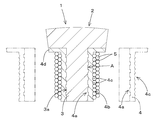
- the insulating member 4 of the stator 1 has a spiral uneven portion 4c and a slot insulating portion 4d.
- the spiral concavo-convex portion 4 c is formed on the outer surface 4 b of the insulating member 4 located outside the circumferential surface A and the axial surface B of the tooth 3.
- a large number of spiral irregularities 4 c are formed in the radial direction of the teeth 3.
- a winding 5 having a circular cross section is fitted into the spiral concavo-convex portion 4c.
- the slot insulating portion 4 d is formed along the inner peripheral surface of the yoke 2. Further, the split surface P of the insulating member 4 is disposed at a position facing one corner of the tooth 3.
- the outer surface 4b of the insulating member 4 is a medium-high arc shape, a spiral concavo-convex portion 4c is formed. Therefore, the concave portion of the spiral concavo-convex portion 4 c guides the winding of the winding 5, and the adhesion between the outer surface 4 b of the insulating member 4 and the winding 5 is increased. Moreover, the convex part between the recessed parts of the spiral concavo-convex part 4c fills the space between the adjacent windings 5, reduces the air layer, and increases the amount of heat transfer between the two.
- the spiral concavo-convex portion 4c can be naturally formed when the winding 5 is wound while being tightened.
- the spiral concave / convex portion 4c is formed in advance by forming a deep spiral concave portion in the insulating member 4, enlargement of the contact area and reduction of the air layer become remarkable.
- the insulating member 4 according to the second embodiment is configured such that one split surface P is greatly opened and fitted to the teeth 3 from the outside, but the split surfaces P are formed at diagonal positions of the teeth 3 and It may be divided in half.
- the insulating member 4 can be insulated not only between the winding 5 and the tooth 3 but also between the winding 5 and the yoke 2 by the slot insulating portion 4d in a state where the insulating member 4 is fitted to the tooth 3.
- the tooth 3 has the unevenness 3a formed only on the circumferential surface A, and the unevenness 3a is not formed on the axial surface B. Accordingly, the insulating member 4 is also formed with the unevenness 4a only on the circumferential surface A so as to fit and fit with the unevenness 3a.
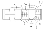
- 8 and 9 show a third embodiment of the stator of the electric motor of the present invention.
- the stator 1 has an undivided annular shape.
- a plurality of teeth 3 are integrally formed on the inner circumferential side of the annular yoke 2 in the circumferential direction.
- the insulating member 4 has a split shape in the axial direction.
- the winding 5 is concentrated winding or distributed winding.
- the teeth 3 are formed with irregularities 3 a on the entire circumference of the circumferential surface A and the axial surface B. Concavities and convexities 4 a are also formed on the entire circumference of the inner peripheral surface of the insulating member 4.
- the insulating member 4 is integrally formed with a slot insulating portion 4 d extending from the portion fitted to the tooth 3 along the inner peripheral surface of the yoke 2.
- the slot insulating portions 4d adjacent to each other in the circumferential direction are integrally formed.
- the half-shaped insulating member 4 is annular and symmetrical in the axial direction.
- the split-shaped insulating member 4 is opposed to each other and fitted to all the teeth 3 at the same time.
- the insulating member 4 of the third embodiment may be divided into a plurality along the annular yoke 2.
- One insulating member 4 may be fitted to a plurality of teeth 3 at the same time.
- a cooling structure for a rotating electrical machine according to the present invention will be described.
- 10 to 13 show a first embodiment of a cooling structure for a rotating electrical machine.
- 10 to 13 show the fixed side of a flat and thin synchronous motor (rotary electric machine 11).
- the rotating electrical machine 11 includes a water jacket 12, a winding 13, a stator 14, a heat conductor 15, and a motor housing 16.
- An annular stator 14 is provided on the inner periphery of the water jacket 12.
- the stator 14 has a large number of teeth 14B.
- a winding 13 is wound around the teeth 14B.
- the heat conductor 15 is molded on the inner peripheral surface 12 b of the water jacket 12 so as to cover the winding 13 and the stator 14.
- the water jacket 12 is mounted in the motor housing 16.
- a permanent magnet embedded rotor 17 (shown in FIG. 11) is disposed inside the stator 14.
- the water jacket 12 is made of an aluminum alloy having a high thermal conductivity and is formed into a cylindrical shape. Inside the water jacket 12, a zigzag-shaped jacket passage 12a is formed in the circumferential direction.
- the jacket passage 12a has a straight hole a1, a communication groove a2, and a communication groove a3.
- the straight hole a ⁇ b> 1 is a hole (passage) along the axial direction, and is configured by perforating the inside of the jacket passage 12 a in parallel in the circumferential direction.
- the communication groove a2 communicates one end of the adjacent straight hole a1.
- the communication groove a3 communicates the other end of the straight hole a1 and the other end of the other straight hole a1 adjacent to the straight hole a1.
- the communication grooves a ⁇ b> 2 and a ⁇ b> 3 are closed by seal rings 22 arranged at both axial ends of the water jacket 12.
- a jacket passage 12a is formed in the water jacket 12 with a width extending between both ends in the axial direction. Both ends of the jacket passage 12 a are open to the outer peripheral surface of the water jacket 12.
- One end of the jacket passage 12a is a refrigerant supply port a4, and the other end is a refrigerant discharge port a5.
- the refrigerant supply port a4 and the refrigerant discharge port a5 are connected to an external refrigerant circulation device so as to circulate cooled refrigerant such as water and oil.
- a plurality of stators 14 are arranged in the circumferential direction so that teeth 14B protrude from the inner peripheral side of the annular yoke 14A.
- the teeth 14B have a tip widening shape, and a winding 13 is wound around the trunk portion with an insulating member 21 interposed therebetween.
- a heat conductor 15 is molded with a resin having high thermal conductivity over the entire stator 14 except for the inner ends of the teeth 14B and the windings 13.
- the stator 14 is a yoke-integrated type in which a large number of teeth 14B project from the inner periphery of one annular yoke 14A.
- the stator 14 may be a stator piece annular coupling type.
- stator 14 forms a stator piece with the divided yoke and one tooth 14B (pole tooth portion) integrated with the divided yoke, and a large number of the stator pieces are arranged in the circumferential direction.
- One annular stator may be configured.
- the stator 14 is formed by laminating a number of silicon steel plates.
- the teeth 14B have two surfaces in the circumferential direction (surface on the slot side) and two surfaces in the axial direction (axial center direction of the stator), and have a rectangular cross section.
- the insulating member 21 is made of resin such as aramid insulating paper or PPS (Polyphenylenesulfide) resin.
- the insulating member 21 has a rectangular tube shape that surrounds the entire circumference of the tooth 14B having a rectangular cross section, or a split shape that surrounds the entire circumference of the tooth 14B in pairs.
- Winding 13 is wound by concentrated winding.
- the insulating member 21 is fitted on the teeth 14 ⁇ / b> B, and concentrated winding is performed while tightening the winding 13 around the outer periphery of the insulating member 21.
- the thermal conductor 15 is a resin having a high thermal conductivity (for example, a resin having a thermal conductivity of 3 to 5 Wm 2 K). By placing the stator 14 in the mold and filling the resin (thermal conductor 15), the resin (thermal conductor 15) is also filled between the windings 13, and the outer shape is rectangular or cross section. It is formed in other shapes.
- the heat conductor 15 is formed by inserting the stator 14 into the water jacket 12 and using the water jacket 12 as a part of the mold to fill the mold with high thermal conductivity resin by injection or transfer.
- the high thermal conductivity resin serves as a filler that fills the space and gaps around the winding 13 and the stator 14 on the inner peripheral surface 12 b side of the water jacket 12. Thereby, the stator 14 is fixed to the water jacket 12 without shrinking.
- the heat conductor 15 has tapered surfaces on both side surfaces in the axial direction of the stator 14.
- the heat conductor 15 has a radially outer axial width W1 wider than the radially inner width W2, and the outer periphery of the width W1 corresponds to substantially the entire width of the water jacket 12 in the axial direction. Thereby, heat can be conducted from the entire outer peripheral surface of the heat conductor 15 to the water jacket 12.
- the heat conductor 15 may be formed with the same width from the outer peripheral portion to the inner peripheral portion. However, the material of the heat conductor 15 can be reduced if the inner peripheral portion is narrowed and the cross-sectional circumferential shape is a fan shape or a trapezoidal shape.
- the motor housing 16 is formed of an iron-based casting such as FC (grey cast iron (also referred to as ordinary cast iron)), FCD (ductile cast iron), or the like.
- FC, FCD, etc. have a tensile strength of 200 to 500 MPa and a thermal conductivity of 20 to 40 W / (mK).
- the aluminum alloy has a tensile strength of 300 MPa and a thermal conductivity of 130 to 180 W / (mK).
- An aluminum alloy that is easy to transmit heat is applied to the water jacket 12, and an iron-based casting having a tensile strength of 300 MPa or more is applied to the motor housing 16 that becomes the outer case. Thereby, the motor housing 16 is used as a structural strength member for protecting the strength of the water jacket 12.
- the water jacket 12 is mounted in the motor housing 16 on the fixed side of the rotating electrical machine 11.
- a stator 14 around which a winding 13 is wound is provided on the inner periphery of the water jacket 12.
- a heat conductor 15 is molded on the inner peripheral surface 12 b of the water jacket 12 so as to cover the windings 13 and the stator 14.
- a refrigerant passage 18 is formed inside the heat conductor 15.
- the water jacket 12 is made of an aluminum alloy having a high thermal conductivity and is formed into a cylindrical shape.
- the water jacket 12 has a circumferential zigzag-shaped jacket passage 12a formed therein.
- the stator 14 is formed by laminating a large number of silicon steel plates.
- the tip of the teeth 14B is not a divergent shape, but has a rectangular cross section from the trunk to the tip.
- the insulating member 21 is made of an elastic resin.
- a winding 13 is wound around the outer periphery of the insulating member 21 by concentrated winding.
- the thermal conductor 15 is formed by molding by placing the stator 14 in a mold and filling a high thermal conductivity resin. When performing this molding, a resin tube, a metal tube, or a rod-like core formed of a heat-meltable material is formed into an annular shape and inserted into the mold, so that the refrigerant A service passage 18 is formed.
- the width of the heat conductor 15 in the axial direction of the stator 14 is gradually narrowed from the outer peripheral portion in contact with the water jacket 12 toward the inner peripheral portion. However, the heat conductor 15 may be formed with the same width from the outer peripheral portion to the inner peripheral portion.
- the heat conductor 15 has a plurality of refrigerant passages 18 formed between the stator 14 and both axial side surfaces.
- Three refrigerant passages 18 are formed on both sides of the stator 14 in the axial direction. Specifically, two refrigerant passages 18 are disposed at positions overlapping the windings 13 and the teeth 14B, and one is disposed at a position overlapping the yoke 14A. The three refrigerant passages 18 are wound around three concentric ring-shaped circles. A common refrigerant supply port member 23 is provided at one end portion of the three refrigerant passages 18, and a common refrigerant discharge port member 24 is provided at the other end portion of the three refrigerant passages 18.
- the refrigerant passage 18 may be only one side surface of the stator 14, and the number of refrigerant passages 18 may be one or a plurality other than three.
- the refrigerant supply port member 23 and the refrigerant discharge port member 24 are connected to a refrigerant circulation device outside the stator 14. As a result, cooled coolant such as water or oil is supplied to the coolant supply port member 23 to flow into the coolant passage 18 and is discharged from the coolant discharge port member 24.
- the three refrigerant passages 18 can also be formed by winding a single passage into a triple helix. In this case, the refrigerant supply port member 23 is connected to one end and the refrigerant discharge port member 24 is connected to the other end.
- the outer peripheral side and the intermediate peripheral side are circular in cross section, and the inner peripheral side is deformed into an oval cross section because the inner peripheral portion of the heat conductor 15 is narrow.
- the refrigerant passage 18 may have a circular, oval, square, or other shape in cross section.
- One or a plurality of refrigerant passages 18 may be disposed on at least one side surface in the axial direction of the stator 14.
- the refrigerant passage 18 can be disposed at a position overlapping the yoke 14A, but is disposed at a position overlapping at least the winding 13 and a position where the coil end can be cooled.
- the refrigerant passage 18 may be formed in a mesh shape or a circumferential zigzag shape in the axial direction and disposed in the heat conductor 15. Moreover, the refrigerant
- the rotating electrical machine 11 conducts and absorbs the resistance heat generated in the winding 13 and the teeth 14B through the yoke 14A to the water jacket 12, and is filled between the windings 13 and is wound between the winding 13, the teeth 14B and the yoke.
- the heat conductor 15 made of high thermal conductivity resin covering 14A is also absorbed. Further, in addition to the direct heat conduction from the yoke 14A, the wide outer peripheral surface of the heat conductor 15 is in contact with the water jacket 12 made of a material having a high heat conductivity, thereby increasing the heat conduction efficiency. Resistance heat can be conducted to the water jacket 12.
- the water jacket 12 can be efficiently cooled by the refrigerant flowing through the jacket passage 12a formed over the entire width. By making the water jacket 12 a part of the mold, the heat conductor 15 can be easily molded.
- the stator 14 can be attached to the water jacket 12 by the heat conductor 15, and the water jacket 12 can be reinforced by the motor housing 16 that is a structurally high-strength member.
- 15 to 18 show a third embodiment of the cooling structure of the rotating electrical machine.
- the third embodiment of FIGS. 15 to 18 shows a stator 31 applied to, for example, a synchronous motor (rotating electric machine) having a permanent magnet embedded rotor.
- the stator 31 is press-fitted and fitted into the inner peripheral surface of the annular outer case 40.
- the stator 31 has a yoke 32, teeth 33, and a winding 35.
- the yoke 32 is annular.
- a plurality of teeth 33 protrude in the inner peripheral side of the yoke 32 and are arranged in the circumferential direction.
- a winding 35 is wound around the tooth 33 with an insulating member 34 interposed therebetween.
- a heat conductor 37 is molded on the entire stator 31 except for the inner diameter ends of the teeth 33 and the windings 35.
- a refrigerant passage 38 is formed inside the heat conductor 37.
- the stator 31 is a yoke-integrated type in which a large number of teeth 33 project from the inner periphery of one annular yoke 32.
- the stator 31 may be a stator piece annular coupling type. That is, the stator 31 forms a stator piece by the divided yoke and one tooth 33 (pole tooth portion) integrated with the divided yoke, and a large number of the stator pieces are arranged in the circumferential direction.
- One annular stator may be configured.
- the stator 31 is formed by laminating a large number of silicon steel plates.
- the teeth 33 have two surfaces in the circumferential direction (surface on the slot side) and two surfaces in the axial direction (axial center direction of the stator), and have a rectangular cross section.
- the insulating member 34 is made of resin such as aramid insulating paper or PPS resin.
- the insulating member 34 has a rectangular tube shape that surrounds the entire circumference of the tooth 33 having a rectangular cross section, or a split shape that surrounds the entire circumference of the tooth 33 in pairs.
- the thermal conductor 37 is a resin having a high thermal conductivity.
- the resin is filled between the windings 35, and the outer shape is formed in a rectangular cross section or other shapes.
- the This molding can be performed before or after the stator 31 is fitted into the outer case 40.
- a resin tube, a metal tube, or a rod-shaped core formed of a heat-meltable material is formed in an annular shape and inserted into a mold. As a result, a refrigerant passage 38 is formed inside the heat conductor 37.
- the refrigerant passages 38 shown in FIGS. 15 to 18 are four. Four refrigerant passages 38 are arranged at positions overlapping the windings 35 and the teeth 33, and one is arranged at a position overlapping the yoke 32. The four refrigerant passages 38 are wound around four concentric ring-shaped circles, and a common refrigerant supply port member 43 is provided at one end of the four refrigerant passages 38. A common refrigerant outlet member 44 is provided.
- the refrigerant supply port member 43 and the refrigerant discharge port member 44 are connected to a refrigerant circulation device outside the stator 31.
- cooled coolant such as water or oil is supplied to the coolant supply port member 43, flows into the coolant passage 38, and is discharged from the coolant discharge port member 44.
- the four refrigerant passages 38 can be formed by winding one passage into a quadruple spiral. In this case, the refrigerant supply port member 43 is connected to one end and the refrigerant discharge port member 44 is connected to the other end.
- FIG. 19 shows a fourth embodiment of the cooling structure of the rotating electric machine.
- the refrigerant passages 38 in the heat conductor 37 are disposed on both side surfaces of the stator 31 in the axial direction.
- Auxiliary passages 46 having an oval cross section are formed on both side surfaces of the yoke 32.
- the auxiliary passage 46 overlaps the side surface in the axial direction of the yoke 32 and overlaps the outer end portion of the winding 35 so that the winding 35 and the yoke 32 can be cooled.
- a cooling path 47 is also formed in the outer case 40 to allow the refrigerant to pass to the inner peripheral side near the yoke 32.
- the refrigerant passage 38 may be formed in a mesh shape or a circumferential zigzag shape in the axial direction and disposed in the heat conductor 37.
- the refrigerant passage 38 may be inserted between the windings 35 adjacent in the circumferential direction from the side of the winding 35.
- the refrigerant passage 38 may be arranged so as to sew the windings 35 adjacent in the circumferential direction.
- the refrigerant passage 38 may have a circular, oval, square, or other shape in cross section.
- One or a plurality of refrigerant passages 38 may be disposed on at least one side surface of the stator 31 in the axial direction.
- the refrigerant passage 38 can be disposed at a position overlapping the yoke 32, but is disposed at a position overlapping at least the winding 35 and a position where the coil end can be cooled.
- a heat conductor 37 made of a high thermal conductivity resin is filled between the windings 35 and covers both side surfaces in the axial direction of the winding 35, the teeth 33 and the yoke 32.
- the resistance heat generated in the winding 35 and the teeth 33 is efficiently conducted and absorbed, and can be removed by the refrigerant flowing through the refrigerant passage 38.
- the heat conductor 37 itself can be cooled by the refrigerant passing through the refrigerant passage 38 and the resistance heat can be taken away, the heat can be efficiently cooled.
- the coolant passage 38 is integrally formed in the heat conductor 37, the number of parts can be reduced and molding is easy.
- the refrigerant passage 38 can be disposed near the coil end of the winding 35 inside the heat conductor 37. By disposing the refrigerant passages 38 on both sides of the winding 35 and both sides of the yoke 32, the stator 31 can be cooled as a whole and uniformly, and the temperature of the winding 35 can be kept low. . Thereby, it becomes possible to lengthen the lifetime of a rotary electric machine. By improving the cooling efficiency by the refrigerant, it becomes possible to reduce structures such as fins in the rotating electric machine and to reduce the output of the forced cooling system. For this reason, it is possible to reduce the vibration and noise of the rotating electrical machine and the forced cooling system.
- the stator 31 has the heat conductor 37 which covers an outer surface
- the outer peripheral surface of the stator 31 and the inner peripheral surface of the outer case 40 can be fixed with rough accuracy. This also enables cost reduction. In the case of a flat rotating electrical machine, a larger cooling area and cooling volume than those without the heat conductor 37 can be secured.
- the present invention is best configured as shown in FIGS. 1 to 19 with respect to the shape of each member and the positional relationship between the front, rear, left, and right in the above-described embodiment. However, it is not limited to the said embodiment, A member, a structure can be variously deformed, and a combination can also be changed.
- the windings 5 are dispersedly wound.
- corrugation 4a of the insulating member 4 is a tetragon
- the jacket passage 12a has communication grooves a2 and a3 formed annularly at both ends of the water jacket 12, respectively, and the circumferential direction of both annular communication grooves a2 and a3. You may make it make the both ends of many linear holes a1 communicate.
- the winding 13 is wound by concentrated winding, you may make it the distributed winding which winds a winding over the several teeth 14B.
- the winding 35 is wound by concentrated winding, but may be distributed winding in which the winding 35 is wound over a plurality of teeth 33.
Abstract
ティースと絶縁部材との間の伝熱量を増大しかつ熱抵抗を減少できるようにする。電動機の固定子(1)は、ヨーク(2)と、ヨーク(2)の内周側の周方向に複数配列されたティース(3)と、ティース(3)に巻かれた巻線(5)と、ティース(3)と巻線(5)との間に介在された弾性樹脂製の絶縁部材(4)とを備えている。ティース(3)の周方向面(A)と軸方向面(B)の内の少なくとも周方向面(A)には、凹凸(3a)が形成されている。絶縁部材(4)の内面には、凹凸(3a)に適合して嵌め合わされる凹凸(4a)が形成されている。
Description
本発明は、単独の駆動源として又はエンジンとともにハイブリッドの駆動源として産業機器に適用される電動機の固定子、及び自動車や産業機器に適用される回転電機の冷却構造に関する。
自動車や、農機、建機、ユーティリティビークル等の産業機器に適用される電動機(各種IPMモータ・ジェネレータを含む。)は、シリーズハイブリッド式又はパラレルハイブリッド式駆動源として機器に搭載されている。このような電動機としては、例えば、永久磁石埋込型同期電動機が用いられている。
このような電動機の固定子は、分割ヨークにティースを突出して分割固定子を形成し、これを多数環状に配置した固定子片環状結合型と、環状ヨークの内周に多数のティースを突出したヨーク一体型とがある。
このような電動機の固定子は、分割ヨークにティースを突出して分割固定子を形成し、これを多数環状に配置した固定子片環状結合型と、環状ヨークの内周に多数のティースを突出したヨーク一体型とがある。
固定子片環状結合型の固定子は、特許文献1に開示されている。特許文献1に開示の固定子は、絶縁処理した分割鉄心の極歯ごとに巻線を巻回した固定子片を環状結合する固定子である。この固定子は、分割鉄心のスロット開口部を絶縁するスロット絶縁板と、弾性を有する絶縁体とを備えている。スロット絶縁板と巻線との間に前記絶縁体を介在させている(請求項1)。これにより、固定子巻線の絶縁性能の経時劣化を少なくしかつ高効率と信頼性を向上させている。
また、電動機のうち、特に扁平薄型モータにおいては、必要長さの冷却水路長を確保するために、ステータ積厚よりも水路幅が大きくなりがちであり、発熱源(巻線及びステータ)との接触面積が限定されて有効な冷却が行い難い。そのため、十分な冷却が行えずに高出力でのモータ連続使用時間が制約される等、使い勝手が悪い状況が生じる。
特許文献2の電動機は、モータハウジング内に設けられたステータ本体および該ステータ本体に巻いて設けられたステータコイルを有するステータと、該ステータに回転可能に内挿されたロータとを含んでいる。ステータ本体端面とモータハウジング内壁面との隙間には樹脂が設けられている。この樹脂は、ステータ本体から突出しているコイルエンド部の表面に設けられたコイルエンドの巻線同士の隙間にもまわりこんでいる。また、モータハウジングを外筒部と内筒部とで二重構造にしてウォータジャケットとし、このウォータジャケットの内部の隙間(ジャケット通路)を通る冷却媒体によってステータコイル及びステータの熱を吸収するように構成されている。
特許文献2の電動機は、モータハウジング内に設けられたステータ本体および該ステータ本体に巻いて設けられたステータコイルを有するステータと、該ステータに回転可能に内挿されたロータとを含んでいる。ステータ本体端面とモータハウジング内壁面との隙間には樹脂が設けられている。この樹脂は、ステータ本体から突出しているコイルエンド部の表面に設けられたコイルエンドの巻線同士の隙間にもまわりこんでいる。また、モータハウジングを外筒部と内筒部とで二重構造にしてウォータジャケットとし、このウォータジャケットの内部の隙間(ジャケット通路)を通る冷却媒体によってステータコイル及びステータの熱を吸収するように構成されている。
また、電動機の固定子は、ヨークから突出したティースにコイルを集中巻き又は分布巻きしている。そして、コイルの銅損で発生する熱、固定子の鉄損で発生する熱を放熱するために、オートマチックトランスミッションフルード(ATF)を用いた直接冷却、外部ケースにウォータジャケットを用いた液冷等が実施されている。
ATF冷却では、コイルと冷媒間の接触面積が小さい。そのため、伝熱量が小さかったり、コイル近傍の冷却が困難であったりしている。また、外部ケースのウォータジャケット冷却では、固定子と外部ケースとの間に空気層があり、熱抵抗が大きい。また、コイルまでの距離が長いので放熱効率が低いものになっている。
ATF冷却では、コイルと冷媒間の接触面積が小さい。そのため、伝熱量が小さかったり、コイル近傍の冷却が困難であったりしている。また、外部ケースのウォータジャケット冷却では、固定子と外部ケースとの間に空気層があり、熱抵抗が大きい。また、コイルまでの距離が長いので放熱効率が低いものになっている。
特許文献3においては、鉄芯コアに巻かれた電磁コイルをモールド樹脂でモールド成形して、モールド樹脂の高い熱伝導率化を利用した技術が開示されている。
また、特許文献4においては、コイルに対して固定子の軸心方向に離間して冷媒供給口を配置して、この冷媒供給口からコイルの軸方向端面と円周方向端面とに冷媒を供給して接触させることにより、冷却効率を向上させるようにした技術が開示されている。
また、特許文献4においては、コイルに対して固定子の軸心方向に離間して冷媒供給口を配置して、この冷媒供給口からコイルの軸方向端面と円周方向端面とに冷媒を供給して接触させることにより、冷却効率を向上させるようにした技術が開示されている。
特許文献1の開示技術は、絶縁体によって経時劣化を少なくすることは期待できる。しかし、絶縁体とティース(分割鉄心)との間及び絶縁体と巻線との間の接触面積が小さくなる。そのため、絶縁体と巻線との間の伝熱量が小さくなる、絶縁体と巻線との間に空気層が生じて熱抵抗が大きくなる、等の問題が発生する可能性がある。
また、特許文献2の開示技術は、ステータ外周からウォータジャケットへ至る伝熱径路に加えて、ステータコイルとステータ表面から樹脂を介してウォータジャケットへ至る伝熱径路を利用できる。そのため、冷却効率を高くすることが可能になっている。しかし、モータハウジング内に冷却媒体流通通路となるジャケット通路を形成しているので、モータハウジング自体は高強度の部材になり難い。また、ジャケット通路を有するモータハウジングとステータとは焼バメにより結合するので、熱抵抗が大きくなって冷却能力の低減を招くことがある。
また、特許文献2の開示技術は、ステータ外周からウォータジャケットへ至る伝熱径路に加えて、ステータコイルとステータ表面から樹脂を介してウォータジャケットへ至る伝熱径路を利用できる。そのため、冷却効率を高くすることが可能になっている。しかし、モータハウジング内に冷却媒体流通通路となるジャケット通路を形成しているので、モータハウジング自体は高強度の部材になり難い。また、ジャケット通路を有するモータハウジングとステータとは焼バメにより結合するので、熱抵抗が大きくなって冷却能力の低減を招くことがある。
また、特許文献3の開示技術は、電磁コイルからモールド樹脂への熱伝導は効率良く行うことができる。しかし、モールド樹脂で外部ケースも形成しなくてはならないため、金属製の外部ケース内に配置すると、モールド樹脂から外部への放熱が困難になる。
また、特許文献4の開示技術は、コイルの周面を直接的に冷却できる。しかし、冷媒はコイルと接触する時間が短いので、冷却効率を高めることは困難になる。
また、特許文献4の開示技術は、コイルの周面を直接的に冷却できる。しかし、冷媒はコイルと接触する時間が短いので、冷却効率を高めることは困難になる。
本発明は、このような従来技術の問題点を解決できるようにした電動機の固定子及び回転電機の冷却構造を提供することを目的とする。
本発明は、ティースの面とこれを包囲する絶縁部材の内面とに凹凸を形成して、ティースの面の凹凸と絶縁部材の内面の凹凸とを適合させて嵌め合わせることにより、ティースと絶縁部材との間の伝熱量を増大しかつ熱抵抗を減少できるようにした電動機の固定子を提供することを目的とする。
本発明は、ティースの面とこれを包囲する絶縁部材の内面とに凹凸を形成して、ティースの面の凹凸と絶縁部材の内面の凹凸とを適合させて嵌め合わせることにより、ティースと絶縁部材との間の伝熱量を増大しかつ熱抵抗を減少できるようにした電動機の固定子を提供することを目的とする。
また、本発明は、ウォータジャケットの内周面に巻線及び固定子を覆って一体化される熱伝導体を設け、このウォータジャケットを別体のモータハウジング内に装着することにより、ウォータジャケットの強度確保と冷却効率の向上ができるようにした回転電機の冷却構造を提供することを目的とする。
また、本発明は、ティースの巻線を覆う高熱伝導率樹脂製の熱伝導体の内部に冷媒用通路を形成することにより、巻線を効率良く冷却できるようにした回転電機の冷却構造を提供することを目的とする。
また、本発明は、ティースの巻線を覆う高熱伝導率樹脂製の熱伝導体の内部に冷媒用通路を形成することにより、巻線を効率良く冷却できるようにした回転電機の冷却構造を提供することを目的とする。
本発明における課題解決のための具体的手段は、次の通りである。
第1に、電動機の固定子1は、ヨーク2と、ヨーク2の内周側の周方向に複数配列されたティース3と、ティース3に巻かれた巻線5と、ティース3と巻線5との間に介在された弾性樹脂製の絶縁部材4とを備え、ティース3の周方向面Aと軸方向面Bの内の少なくとも周方向面Aには凹凸3aが形成され、絶縁部材4の内面には凹凸3aに適合して嵌め合わされる凹凸4aが形成されている。
第1に、電動機の固定子1は、ヨーク2と、ヨーク2の内周側の周方向に複数配列されたティース3と、ティース3に巻かれた巻線5と、ティース3と巻線5との間に介在された弾性樹脂製の絶縁部材4とを備え、ティース3の周方向面Aと軸方向面Bの内の少なくとも周方向面Aには凹凸3aが形成され、絶縁部材4の内面には凹凸3aに適合して嵌め合わされる凹凸4aが形成されている。
第2に、絶縁部材4は、ティース3を包囲し且つティース3の周方向面A及び軸方向面Bの外方に位置する外面4bを有し、外面4bは巻線5の巻き方向で中高円弧状に形成されている。
第3に、巻線5は断面円形であり、外面4bは巻線5が嵌め入れられる取付部4cを有し、取付部4cはティース3の径方向に多数配列して形成されている。
第3に、巻線5は断面円形であり、外面4bは巻線5が嵌め入れられる取付部4cを有し、取付部4cはティース3の径方向に多数配列して形成されている。
第4に、絶縁部材4は二つ割り形状であり、二つ割り形状の一方の絶縁部材4と他方の絶縁部材4とは対向しており、対向する一方の絶縁部材4と他方の絶縁部材4とはティース3の周方向面Aと軸方向面Bとを包囲している。
第5に、回転電機の冷却構造は、冷媒を通すジャケット通路12aが内部に形成されたウォータジャケット12と、ウォータジャケット12の内周に設けられた環状の固定子14と、固定子14に巻かれた巻線13と、ウォータジャケット12の内周面12bに一体化される熱伝導体15と、ウォータジャケット12と別体のモータハウジング16とを備え、熱伝導体15は、高熱伝導率の樹脂であって、巻線13及び固定子14を覆ってモールド成形され、ウォータジャケット12は、高熱伝導率の材料で形成されるとともにモータハウジング16内に装着されている。
第5に、回転電機の冷却構造は、冷媒を通すジャケット通路12aが内部に形成されたウォータジャケット12と、ウォータジャケット12の内周に設けられた環状の固定子14と、固定子14に巻かれた巻線13と、ウォータジャケット12の内周面12bに一体化される熱伝導体15と、ウォータジャケット12と別体のモータハウジング16とを備え、熱伝導体15は、高熱伝導率の樹脂であって、巻線13及び固定子14を覆ってモールド成形され、ウォータジャケット12は、高熱伝導率の材料で形成されるとともにモータハウジング16内に装着されている。
第6に、ウォータジャケット12はアルミニウム合金で形成され、モータハウジング16は鉄系鋳物で形成され、熱伝導体15は、ウォータジャケット12をモータハウジング16内に装着する前に、ウォータジャケット12の内周面12bに、巻線13及び固定子14を覆ってモールド成形されている。
第7に、ウォータジャケット12は円筒形状であって、ジャケット通路12aは軸心方向の両端間に亘る幅で周方向にジグザグ形状に形成されている。
第7に、ウォータジャケット12は円筒形状であって、ジャケット通路12aは軸心方向の両端間に亘る幅で周方向にジグザグ形状に形成されている。
第8に、熱伝導体15は、固定子14の軸心方向の幅が、径内側より径外側が広く形成され、熱伝導体15の径外側は、ウォータジャケット12の軸心方向の略全幅に対応している。
第9に、熱伝導体15の内部には冷媒用通路18が形成され、冷媒用通路18は、固定子14及び巻線13とオーバラップしている。
第9に、熱伝導体15の内部には冷媒用通路18が形成され、冷媒用通路18は、固定子14及び巻線13とオーバラップしている。
第10に、回転電機の冷却構造は、円環状のヨーク32と、ヨーク32から突出したティース33と、ティース33に巻かれた巻線35と、ヨーク32、ティース33及び巻線35を有する固定子31と、高熱伝導率の樹脂からなる熱伝導体37とを備え、熱伝導体37は、巻線35間を充填しながら固定子31の軸心方向の両側面にモールド成形されており、熱伝導体37の内部には、冷媒流通用の通路38が形成されている。
第11に、ティース33と巻線35との間に介在された弾性樹脂製の絶縁部材34を備え、巻線35は、絶縁部材34を介してティース33に集中巻きされており、冷媒用通路38は巻線35とオーバラップして配置されている。
第12に、冷媒用通路38は、固定子31の軸心方向の少なくとも一方の側面に、軸心方向視において環形状、螺旋形状、網目形状又は周方向ジグザグ形状に形成されている。
第12に、冷媒用通路38は、固定子31の軸心方向の少なくとも一方の側面に、軸心方向視において環形状、螺旋形状、網目形状又は周方向ジグザグ形状に形成されている。
本発明の電動機の固定子によれば、ティースと絶縁部材との間の伝熱量を増大しかつ熱抵抗を減少することができる。
即ち、ティース3の周方向面Aと軸方向面Bの内の少なくとも周方向面Aには凹凸3aが形成され、絶縁部材4の内面には凹凸3aに適合して嵌め合わされる凹凸4aが形成されている。そのため、絶縁部材4の内面はティース3の周方向面Aと大面積で密着でき、空気層が減少し、両者の間の伝熱量を増大するとともに熱抵抗を減少できる。
即ち、ティース3の周方向面Aと軸方向面Bの内の少なくとも周方向面Aには凹凸3aが形成され、絶縁部材4の内面には凹凸3aに適合して嵌め合わされる凹凸4aが形成されている。そのため、絶縁部材4の内面はティース3の周方向面Aと大面積で密着でき、空気層が減少し、両者の間の伝熱量を増大するとともに熱抵抗を減少できる。
また、絶縁部材4の外面4bは巻線5の巻き方向で中高円弧状に形成されている。そのため、絶縁部材4の外面4bと巻線5との間の空気層が減少し、両者の間の伝熱量を増大することができるとともに熱抵抗を減少できる。
また、巻線5は断面円形であり、外面4bは巻線5が嵌め入れられる螺旋凹凸部(凹部及び凸部を含む螺旋状の取付部)4cを有し、取付部4cはティース3の径方向に多数配列して形成されている。そのため、絶縁部材4の外面4bと巻線5とが大面積で密着できる。これにより、絶縁部材4の外面4bと巻線5との間の空気層が減少し、両者の間の伝熱量を増大するとともに熱抵抗を減少できる。
また、巻線5は断面円形であり、外面4bは巻線5が嵌め入れられる螺旋凹凸部(凹部及び凸部を含む螺旋状の取付部)4cを有し、取付部4cはティース3の径方向に多数配列して形成されている。そのため、絶縁部材4の外面4bと巻線5とが大面積で密着できる。これにより、絶縁部材4の外面4bと巻線5との間の空気層が減少し、両者の間の伝熱量を増大するとともに熱抵抗を減少できる。
また、絶縁部材4は二つ割り形状であり、二つ割り形状の一方の絶縁部材4と他方の絶縁部材4とは対向しており、対向する一方の絶縁部材4と他方の絶縁部材4とはティース3の周方向面Aと軸方向面Bとを包囲している。そのため、絶縁部材4の製作及び装着がきわめて容易にできる。
また、本発明の回転電機の冷却構造によれば、回転電機のウォータジャケットの強度確保と冷却効率の向上が可能になる。
また、本発明の回転電機の冷却構造によれば、回転電機のウォータジャケットの強度確保と冷却効率の向上が可能になる。
即ち、冷媒を通すジャケット通路12aが内部に形成されたウォータジャケット12と、ウォータジャケット12の内周に設けられた環状の固定子14と、固定子14に巻かれた巻線13と、ウォータジャケット12の内周面12bに一体化される熱伝導体15と、ウォータジャケット12と別体のモータハウジング16とを備え、熱伝導体15は、高熱伝導率の樹脂であって、巻線13及び固定子14を覆ってモールド成形され、ウォータジャケット12は、高熱伝導率の材料で形成されるとともにモータハウジング16内に装着されている。そのため、冷却効率を向上しながらウォータジャケット12の補強強度も確保できる。
また、ウォータジャケット12はアルミニウム合金で形成され、モータハウジング16は鉄系鋳物で形成され、熱伝導体15は、ウォータジャケット12をモータハウジング16内に装着する前に、ウォータジャケット12の内周面12bに、巻線13及び固定子14を覆ってモールド成形されている。つまり、ウォータジャケット12を熱伝導率の高いアルミニウム合金で形成しながら強度の高い鉄系鋳物製モータハウジング16に装着している。そのため、冷却効率を向上しながらウォータジャケット12の強度をより確実に確保できる。
また、ウォータジャケット12は円筒形状であって、ジャケット通路12aは軸心方向の両端間に亘る幅で周方向にジグザグ形状に形成されている。そのため、流通冷媒はウォータジャケット12を効率良く冷却することができる。
また、熱伝導体15は、固定子14の軸心方向の幅が、径内側より径外側が広く形成され、熱伝導体15の径外側は、ウォータジャケット12の軸心方向の略全幅に対応している。そのため、少ない材料で熱伝導体15からウォータジャケット12への熱伝導を効率良くかつ有効的に行われる。
また、熱伝導体15は、固定子14の軸心方向の幅が、径内側より径外側が広く形成され、熱伝導体15の径外側は、ウォータジャケット12の軸心方向の略全幅に対応している。そのため、少ない材料で熱伝導体15からウォータジャケット12への熱伝導を効率良くかつ有効的に行われる。
また、熱伝導体15の内部には冷媒用通路18が形成され、冷媒用通路18は、固定子14及び巻線13とオーバラップしている。そのため、固定子14及び巻線13の近くで熱伝導体15自体を効率良く冷却することができる。
また、本発明の回転電機の冷却構造によれば、巻線を効率良く冷却できる。
即ち、円環状のヨーク32と、ヨーク32から突出したティース33と、ティース33に巻かれた巻線35と、ヨーク32、ティース33及び巻線35を有する固定子31と、高熱伝導率の樹脂からなる熱伝導体37とを備え、熱伝導体37は、巻線35間を充填しながら固定子31の軸心方向の両側面にモールド成形されており、熱伝導体37の内部には、冷媒流通用の通路38が形成されている。そのため、大きい体積の熱伝導体37で巻線35から抵抗少なく熱を奪うことができ、その熱を熱伝導体37内で冷媒用通路38を通る冷媒で効率良く冷却することができる。
また、本発明の回転電機の冷却構造によれば、巻線を効率良く冷却できる。
即ち、円環状のヨーク32と、ヨーク32から突出したティース33と、ティース33に巻かれた巻線35と、ヨーク32、ティース33及び巻線35を有する固定子31と、高熱伝導率の樹脂からなる熱伝導体37とを備え、熱伝導体37は、巻線35間を充填しながら固定子31の軸心方向の両側面にモールド成形されており、熱伝導体37の内部には、冷媒流通用の通路38が形成されている。そのため、大きい体積の熱伝導体37で巻線35から抵抗少なく熱を奪うことができ、その熱を熱伝導体37内で冷媒用通路38を通る冷媒で効率良く冷却することができる。
また、ティース33と巻線35との間に介在された弾性樹脂製の絶縁部材34を備え、巻線35は、絶縁部材34を介してティース33に集中巻きされており、冷媒用通路38は巻線35とオーバラップして配置されている。そのため、巻線35間にも高熱伝導率の樹脂を充填して熱伝導体37をモールド成形でき、巻線35の全周から熱伝導体37へ熱伝導ができ、その熱を巻線35とオーバラップ配置した冷媒用通路38の冷媒で効率よく冷却することができる。
また、冷媒用通路38は、固定子31の軸心方向の少なくとも一方の側面に、軸心方向視において環形状、螺旋形状、網目形状又は周方向ジグザグ形状に形成されている。そのため、固定子31の軸心方向の側面は広い面積を有し、その広い面積部分で熱伝導体37の冷却ができ、冷却効率を高くすることができる。
以下、本発明の実施の形態を図面に基づいて説明する。
先ず、本発明の電動機の固定子について説明する。
図1~5は、本発明の電動機の固定子の第1実施形態を示している。第1実施形態の固定子1は、永久磁石埋込型同期電動機に適用される。固定子1は、ヨーク2、ティース3、絶縁部材4及び巻線5を有している。ヨーク2は環状である。ティース3は、ヨーク2の内周側に周方向に複数配列されている。ティース3には絶縁部材4を介在して巻線5が巻かれている。
先ず、本発明の電動機の固定子について説明する。
図1~5は、本発明の電動機の固定子の第1実施形態を示している。第1実施形態の固定子1は、永久磁石埋込型同期電動機に適用される。固定子1は、ヨーク2、ティース3、絶縁部材4及び巻線5を有している。ヨーク2は環状である。ティース3は、ヨーク2の内周側に周方向に複数配列されている。ティース3には絶縁部材4を介在して巻線5が巻かれている。
第1実施形態の固定子1は、固定子片環状結合型の固定子を構成する固定子片である。即ち、第1実施形態の固定子1である固定子片(以下、分割固定子1という場合がある)は、周方向に多数個が配列されて1個の環状の固定子を構成している。各固定子1(固定子片、分割鉄心)は、ヨーク2(分割ヨーク)と、このヨーク2に一体となった1つのティース3(極歯部)とを有する。
固定子1は多数枚の珪素鋼板を積層して形成されている。ティース3は、2つの周方向の面A(スロット側の面)(以下、周方向面Aという)と、2つの軸方向(固定子の軸心方向)の面B(以下、軸方向面Bという)とを有しており、断面矩形状になっている。周方向面Aには凹凸3aが形成されている。軸方向面Bにも凹凸3aが形成されている。
ティース3の周方向面Aの凹凸3aは、固定子1を珪素鋼板からプレス加工して製作する際に形成される。軸方向面Bの凹凸3aは、表面側の珪素鋼板に表面加工を施すことにより形成される。周方向面Aの凹凸3aは、周方向面Aに凸条の帯を径方向(環状固定子の径方向)に複数本間隔をおいて形成している。軸方向面Bの凹凸3aは、軸方向面Bに凸条の帯を径方向(環状固定子の径方向)に複数本間隔をおいて形成している。周方向面Aの凹凸3aと軸方向面Bの凹凸3aとは、連続であっても断続であってもよい。
ティース3の周方向面Aの凹凸3aは、固定子1を珪素鋼板からプレス加工して製作する際に形成される。軸方向面Bの凹凸3aは、表面側の珪素鋼板に表面加工を施すことにより形成される。周方向面Aの凹凸3aは、周方向面Aに凸条の帯を径方向(環状固定子の径方向)に複数本間隔をおいて形成している。軸方向面Bの凹凸3aは、軸方向面Bに凸条の帯を径方向(環状固定子の径方向)に複数本間隔をおいて形成している。周方向面Aの凹凸3aと軸方向面Bの凹凸3aとは、連続であっても断続であってもよい。
絶縁部材4は、シリコンゴム、PPT樹脂等の弾性樹脂で形成されている。絶縁部材4は、断面矩形状のティース3の全周を包囲する四角筒形状である。絶縁部材4は、ティース3の周方向面Aと軸方向面Bとに対面する内面に、ティース3の凹凸3aに適合して嵌め合わされる凹凸4aが形成されている。
即ち、絶縁部材4の内周面には、凹条溝と凸条が形成されている。絶縁部材4の凹条溝には、ティース3の周方向面Aの凸条と軸方向面Bの凸条とが嵌め入れられる。絶縁部材4の凸条は、凹条溝の間に形成されている。この凸条は、ティース3の周方向面Aの凹条溝と軸方向面Bの凹条溝とに嵌め入れられる。
即ち、絶縁部材4の内周面には、凹条溝と凸条が形成されている。絶縁部材4の凹条溝には、ティース3の周方向面Aの凸条と軸方向面Bの凸条とが嵌め入れられる。絶縁部材4の凸条は、凹条溝の間に形成されている。この凸条は、ティース3の周方向面Aの凹条溝と軸方向面Bの凹条溝とに嵌め入れられる。
ティース3の凸条が絶縁部材4の凹条溝に嵌め入れられることにより、凸条及び凹条溝が面接触するとともに、凸条及び凹条溝以外の面も面接触する状態となる。そのため、ティース3の周方向面Aの凹凸3aと絶縁部材4の凹凸4aとは適合して嵌め合わされることになる。これにより、ティース3の周方向面Aと絶縁部材4との接触面積が凹凸のない場合に比べて大きくなる。また、ティース3の周方向面Aと絶縁部材4との間に、空気層が形成され難くなる。また、ティース3に対する絶縁部材4の嵌め合わせの位置が不動になる。
ティース3の周方向面A及び軸方向面Bの外方に位置する絶縁部材4の外面4bは、巻線5の巻き方向で中高円弧状(蒲鉾形)に形成されている。即ち、絶縁部材4の外面4bは、巻線5の巻き方向の始端側と終端側の中間位置が高くなる円弧状に形成されている。絶縁部材4は、内周面が四角形であるのに対して外面4bは円形に近づけられている。これにより、巻線5が巻きやすくなり、また外面4bと巻線5との間に空隙が形成されないようになっている。
この絶縁部材4はティース3の全周を2個一対で包囲する二つ割り形状である。二つ割りの一方の絶縁部材4と他方の絶縁部材4とは対称形状であり対向している。絶縁部材4は、対向する2つでティース3の周方向面Aと軸方向面Bとを包囲する。図4に示すように、絶縁部材4の割り面Pはティース3の軸方向面Bに対向する位置にある。図1、2に仮想線で示す如く、二つ割り形状の絶縁部材4はそれぞれスロット側からティース3に嵌め合わされる。
図5に示すように、この割り面Pはティース3の周方向面Aに対向する位置にあってもよい。この場合は、二つ割り形状の絶縁部材4を軸方向からティース3に嵌め合わせる。
巻線5は集中巻きで巻かれている。ティース3に絶縁部材4を嵌め合わせて、その絶縁部材4の外周に巻線5を締めながら集中巻きして周方向に所要角度の分割固定子1を構成する。そして、この分割固定子1を周方向に多数配列して環状の固定子を構成する。
巻線5は集中巻きで巻かれている。ティース3に絶縁部材4を嵌め合わせて、その絶縁部材4の外周に巻線5を締めながら集中巻きして周方向に所要角度の分割固定子1を構成する。そして、この分割固定子1を周方向に多数配列して環状の固定子を構成する。
分割固定子1は、1つのティース3に対して二つ割り形状の絶縁部材4を嵌め合わせて、ティース3の周方向面A及び軸方向面Bの凹凸3aに絶縁部材4の内面の凹凸4aを適合させて嵌め合わせる。これにより、ティース3の外面と絶縁部材4の内面とは、凹凸の分だけ接触面積が増えた状態、空気層のない状態、絶縁部材4の位置ズレのない状態で密着する。
ティース3に嵌め合わされた絶縁部材4に巻線5を螺旋状に集中巻きしていくと、絶縁部材4の外面4bが巻き方向で中高円弧状であるので、断面四角形のティース3に対して円形に近づけて巻くことができる。これにより、外面4bでの巻線5の密着性が良好になる。また、ティース3のエッジ部に対向する位置での巻線5の屈曲が穏やかになることにより、巻線5と絶縁部材4とが広い面積で接触する。
絶縁部材4の外面4bに断面円形の巻線5が嵌め入れられる螺旋凹凸部(取付部)4cを形成していると、螺旋凹凸部4cの凹部に巻線5が入り、螺旋凹凸部4cの凸部が巻線5間の間隙を占有する。そのため、絶縁部材4と巻線5とは、凹凸の分だけ接触面積が増えた状態、空気層を排除した状態、巻線5の位置ズレのない状態で密着する。また、巻線5を絶縁部材4に対して螺旋状に巻く工程が容易になる。
このように、固定子1は、ティース3に凹凸3aを形成して、この凹凸3aに絶縁部材4の内面の凹凸4aを適合させて嵌め合わしている。これにより、ティース3と絶縁部材4とは大面積で空気層のない密着した嵌め合わせとなる。また、ティース3と絶縁部材4との間の伝熱量が大きくかつ熱抵抗が小さくなる。そのため、モータの冷却効率を向上でき、組立て作業性及び信頼性も向上できる。これによって、フィン等の冷却構造物の削減や、強制冷却システムの低出力化、低コスト化が可能になる。また、絶縁部材4の外面4bを中高円弧状に形成したり、螺旋凹凸部4cを形成したりすることにより、絶縁部材4の外面4bと巻線5をより大面積で空気層の少ない密着巻きができる。そのため、ティース3のエッジ部に対向する位置でも、巻線5が絶縁部材4と接触することにより絶縁破壊を抑制して、モータ寿命を長くすることが可能になる。
図6,7は、本発明の電動機の固定子の第2実施形態を示している。第2実施形態において、固定子1の絶縁部材4は、螺旋凹凸部4cとスロット絶縁部4dとを有している。螺旋凹凸部4cは、ティース3の周方向面A及び軸方向面Bの外方に位置する絶縁部材4の外面4bに形成されている。螺旋凹凸部4cは、ティース3の径方向に多数配列して形成されている。螺旋凹凸部4cには、断面円形の巻線5が嵌め入れられる。スロット絶縁部4dは、ヨーク2の内周面に沿って形成されている。また、絶縁部材4の割り面Pはティース3の一角のエッジ部に対向する位置に配置されている。
絶縁部材4の外面4bは中高円弧状でありながら螺旋凹凸部4cが形成されている。そのため、螺旋凹凸部4cの凹部が巻線5の巻きを案内するとともに絶縁部材4の外面4bと巻線5との密着を大面積とする。また、螺旋凹凸部4cの凹部間の凸部が隣接する巻線5の間の空間を埋め、空気層を減少させて両者の間の伝熱量を増大する。
絶縁部材4を低硬度の弾性樹脂で形成すると、巻線5を締め付けながら巻き付けたときに自然に螺旋凹凸部4cを形成することができる。しかし、絶縁部材4に予め深い螺旋凹部を形成することで、螺旋凹凸部4cを形成しておく方が、密着面積の拡大、空気層の減少は顕著となる。
絶縁部材4を低硬度の弾性樹脂で形成すると、巻線5を締め付けながら巻き付けたときに自然に螺旋凹凸部4cを形成することができる。しかし、絶縁部材4に予め深い螺旋凹部を形成することで、螺旋凹凸部4cを形成しておく方が、密着面積の拡大、空気層の減少は顕著となる。
この第2実施形態の絶縁部材4は、1つの割り面Pを大きく開いてティース3に外方から嵌め合わせることになるが、ティース3の対角位置に割り面Pを形成して、対角線で二つ割りにしてもよい。また、絶縁部材4はティース3に嵌合した状態で、巻線5とティース3との間だけでなく、スロット絶縁部4dによって巻線5とヨーク2との間の絶縁もできる。
なお、第2実施形態では、ティース3は周方向面Aにのみ凹凸3aが形成され、軸方向面Bには凹凸3aが形成されていない。従って、絶縁部材4も周方向面Aにのみ、凹凸3aと適合して嵌め合わされる凹凸4aが形成されている。
図8,9は、本発明の電動機の固定子の第3実施形態を示している。第3実施形態において、固定子1は非分割の環状形状である。環状のヨーク2の内周側に周方向に複数のティース3が一体成形されている。絶縁部材4は軸方向に二つ割り形状である。巻線5は集中巻き又は分散巻きになっている。
図8,9は、本発明の電動機の固定子の第3実施形態を示している。第3実施形態において、固定子1は非分割の環状形状である。環状のヨーク2の内周側に周方向に複数のティース3が一体成形されている。絶縁部材4は軸方向に二つ割り形状である。巻線5は集中巻き又は分散巻きになっている。
ティース3は周方向面A及び軸方向面Bの全周に凹凸3aが形成されている。絶縁部材4にも内周面の全周に凹凸4aが形成されている。
絶縁部材4は、ティース3に嵌め合わされる部分からヨーク2の内周面に沿うスロット絶縁部4dが一体形成されている。周方向に隣り合うスロット絶縁部4d同士は、一体に形成されている。二つ割り形状の絶縁部材4は、環状でかつ軸方向に対称形状である。二つ割り形状の絶縁部材4を対向させて、全ティース3に同時に嵌め合わせる構成になっている。
絶縁部材4は、ティース3に嵌め合わされる部分からヨーク2の内周面に沿うスロット絶縁部4dが一体形成されている。周方向に隣り合うスロット絶縁部4d同士は、一体に形成されている。二つ割り形状の絶縁部材4は、環状でかつ軸方向に対称形状である。二つ割り形状の絶縁部材4を対向させて、全ティース3に同時に嵌め合わせる構成になっている。
この第3実施形態の絶縁部材4は、環状ヨーク2に沿って複数に分割してもよい。また、1個の絶縁部材4を複数のティース3に同時に嵌め合わせてもよい。
次に、本発明の回転電機の冷却構造について説明する。
図10~13は回転電機の冷却構造の第1実施形態を示している。図10~図13は、扁平薄型の同期電動機(回転電機11)の固定側を示している。回転電機11は、ウォータジャケット12、巻線13、固定子14、熱伝導体15及びモータハウジング16を備えている。ウォータジャケット12の内周に環状の固定子14が設けられている。固定子14は多数のティース14Bを有している。ティース14Bには巻線13が巻かれている。熱伝導体15は、巻線13及び固定子14を覆ってウォータジャケット12の内周面12bにモールド成形されている。ウォータジャケット12はモータハウジング16内に装着されている。固定子14の内側には永久磁石埋込型のロータ17(図11に示す)が配置される。
ウォータジャケット12は高熱伝導率のアルミニウム合金で円筒形状に形成されている。ウォータジャケット12の内部には、周方向にジグザグ形状のジャケット通路12aが形成されている。このジャケット通路12aは、直線孔a1と、連通溝a2と、連通溝a3とを有している。直線孔a1は、軸方向に沿った孔(通路)であって、ジャケット通路12aの内部を周方向に多数本平行に穿孔することにより構成されている。連通溝a2は、隣接する直線孔a1の一端を連通する。連通溝a3は、直線孔a1の他端と、当該直線孔a1に隣接する他の直線孔a1の他端とを連通する。
連通溝a2、a3はウォータジャケット12の軸心方向両端に配置されるシール環22によって閉鎖されている。ウォータジャケット12には軸心方向の両端間に亘る幅でジャケット通路12aが形成されている。
ジャケット通路12aの両端はウォータジャケット12の外周面に開口している。ジャケット通路12aの一端は冷媒供給口a4となり、他端は冷媒吐出口a5となっている。冷媒供給口a4と冷媒吐出口a5は、外部の冷媒循環装置に接続され、冷却した水、油等の冷媒を循環可能にしている。
ジャケット通路12aの両端はウォータジャケット12の外周面に開口している。ジャケット通路12aの一端は冷媒供給口a4となり、他端は冷媒吐出口a5となっている。冷媒供給口a4と冷媒吐出口a5は、外部の冷媒循環装置に接続され、冷却した水、油等の冷媒を循環可能にしている。
固定子14は、環状のヨーク14Aの内周側にティース14Bが突出して周方向複数配列されている。ティース14Bは先端末広がり形状であって、その胴部には絶縁部材21を介在して巻線13が巻かれている。ティース14B及び巻線13の径内端を残して固定子14の全体に高熱伝導率の樹脂で熱伝導体15がモールド成形されている。
固定子14は、1つの環状のヨーク14Aの内周に多数のティース14Bを突設したヨーク一体型のものである。しかし、固定子14は、固定子片環状結合型であってもよい。即ち、固定子14は、分割ヨークと、当該分割ヨークに一体となった1つのティース14B(極歯部)とで固定子片を形成し、その固定子片を周方向に多数個配列して1個の環状の固定子を構成してもよい。
固定子14は、1つの環状のヨーク14Aの内周に多数のティース14Bを突設したヨーク一体型のものである。しかし、固定子14は、固定子片環状結合型であってもよい。即ち、固定子14は、分割ヨークと、当該分割ヨークに一体となった1つのティース14B(極歯部)とで固定子片を形成し、その固定子片を周方向に多数個配列して1個の環状の固定子を構成してもよい。
固定子14は多数枚の珪素鋼板を積層して形成している。ティース14Bは周方向の2面(スロット側の面)と軸方向(固定子の軸心方向)の2面とを有し、断面矩形状になっている。
絶縁部材21は、アラミド絶縁紙あるいはPPS(Polyphenylenesulfide)樹脂等の樹脂で形成されている。絶縁部材21は、断面矩形状のティース14Bの全周を包囲する四角筒形状、または、ティース14Bの全周を2個一対で包囲する二つ割り形状になっている。
絶縁部材21は、アラミド絶縁紙あるいはPPS(Polyphenylenesulfide)樹脂等の樹脂で形成されている。絶縁部材21は、断面矩形状のティース14Bの全周を包囲する四角筒形状、または、ティース14Bの全周を2個一対で包囲する二つ割り形状になっている。
巻線13は集中巻きで巻かれている。ティース14Bに絶縁部材21を嵌め合わせて、その絶縁部材21の外周に巻線13を締めながら集中巻きしている。
熱伝導体15は、熱伝導率の高い樹脂(例えば熱伝導率3~5Wm2Kの樹脂)である。金型内に固定子14を配置しておいて樹脂(熱伝導体15)を充填することにより、巻線13間にも樹脂(熱伝導体15)が充填され、外形も断面矩形状又はそれ以外の形状に形成される。
熱伝導体15は、熱伝導率の高い樹脂(例えば熱伝導率3~5Wm2Kの樹脂)である。金型内に固定子14を配置しておいて樹脂(熱伝導体15)を充填することにより、巻線13間にも樹脂(熱伝導体15)が充填され、外形も断面矩形状又はそれ以外の形状に形成される。
この熱伝導体15は、固定子14をウォータジャケット12内に嵌入して、ウォータジャケット12を金型の一部に利用して、金型内に高熱伝導率樹脂を射出又はトランスファーにて充填して成形する。高熱伝導率樹脂はウォータジャケット12の内周面12b側でかつ巻線13及び固定子14廻りの空間及び隙間に充填される充填剤となっている。これにより、固定子14は焼バメしなくとも、ウォータジャケット12に固定される。
熱伝導体15は固定子14の軸心方向の両側面がテーパ面となっている。熱伝導体15は、径外側の軸心方向の幅W1が径内側の幅W2より広く形成され、その幅W1の外周部はウォータジャケット12の軸心方向の略全幅に対応している。これにより、熱伝導体15の全外周面からウォータジャケット12へ熱を伝導できるようにしている。
熱伝導体15は、外周部から内周部まで同一幅に形成してもよい。しかし、熱伝導体15は、内周部を狭くして、断面周方向形状を扇形状又は台形状にした方が材料を削減できる。
熱伝導体15は、外周部から内周部まで同一幅に形成してもよい。しかし、熱伝導体15は、内周部を狭くして、断面周方向形状を扇形状又は台形状にした方が材料を削減できる。
モータハウジング16は、FC(ねずみ鋳鉄(普通鋳鉄ともいう))、FCD(ダクタイル鋳鉄)等の鉄系鋳物で形成されている。モータハウジング16は、別個に形成したウォータジャケット12の外周に嵌め合わされて装着される。
FC、FCD等は引張強さが200~500MPa、熱伝導率が20~40W/(mK)である。アルミニウム合金は引張強さが300MPa、熱伝導率が130~180W/(mK)である。熱の伝わり易いアルミニウム合金をウォータジャケット12に適用し、外部ケースになるモータハウジング16に引張強さ300MPa以上の鉄系鋳物を適用している。これにより、モータハウジング16をウォータジャケット12の強度保護用の構造強度部材にしている。
FC、FCD等は引張強さが200~500MPa、熱伝導率が20~40W/(mK)である。アルミニウム合金は引張強さが300MPa、熱伝導率が130~180W/(mK)である。熱の伝わり易いアルミニウム合金をウォータジャケット12に適用し、外部ケースになるモータハウジング16に引張強さ300MPa以上の鉄系鋳物を適用している。これにより、モータハウジング16をウォータジャケット12の強度保護用の構造強度部材にしている。
図14に示す回転電機の冷却構造の第2実施形態において、回転電機11の固定側は、モータハウジング16内にウォータジャケット12を装着している。このウォータジャケット12の内周に巻線13を巻回した固定子14を設けている。これら巻線13及び固定子14を覆ってウォータジャケット12の内周面12bに熱伝導体15をモールド成形している。この熱伝導体15の内部に冷媒用通路18を形成している。
ウォータジャケット12は高熱伝導率のアルミニウム合金で円筒形状に形成されている。ウォータジャケット12は、内部に周方向ジグザグ形状のジャケット通路12aが形成されている。固定子14は多数枚の珪素鋼板を積層して形成されている。ティース14Bの先端は末広がり形状ではなく、胴部から先端まで断面矩形状となっている。絶縁部材21は弾性樹脂で形成されている。絶縁部材21の外周に巻線13が集中巻きで巻かれている。
熱伝導体15は、金型内に固定子14を配置しておいて高熱伝導率樹脂を充填するモールド成形により形成されている。このモールド成形を行う際に、樹脂製の管、金属製の管または熱溶解可能な材料で形成された棒状中子等を、環状に形成して金型内に挿入しておくことにより、冷媒用通路18が形成されている。
熱伝導体15は固定子14の軸心方向の幅がウォータジャケット12と接する外周部から内周部側へ次第に幅狭になっている。しかし、熱伝導体15は、外周部から内周部まで同一幅に形成してもよい。熱伝導体15は、固定子14と軸心方向両側面との間に複数本の冷媒用通路18が形成されている。
熱伝導体15は固定子14の軸心方向の幅がウォータジャケット12と接する外周部から内周部側へ次第に幅狭になっている。しかし、熱伝導体15は、外周部から内周部まで同一幅に形成してもよい。熱伝導体15は、固定子14と軸心方向両側面との間に複数本の冷媒用通路18が形成されている。
冷媒用通路18は固定子14の軸心方向両側にそれぞれ3本形成されている。具体的には、冷媒用通路18は、巻線13及びティース14Bとオーバラップした位置に2本、ヨーク14Aとオーバラップした位置に1本配置されている。この3本の冷媒用通路18は、同心円環形状の3本円に巻いている。3本の冷媒用通路18の一端部に共通の冷媒供給口部材23を設け、3本の冷媒用通路18の他端部に共通の冷媒吐出口部材24を設けている。なお、冷媒用通路18は固定子14の一側面だけでもよく、本数も1本又は3本以外の複数本でもよい。
冷媒供給口部材23及び冷媒吐出口部材24は、固定子14の外部の冷媒循環装置に接続されている。これにより、冷却した水、油等の冷媒を冷媒供給口部材23に供給して冷媒用通路18に流動させ、冷媒吐出口部材24から吐出させるようになっている。
3本の冷媒用通路18は、1本の通路を3重螺旋に巻いて形成することもできる。この場合は、一端部に冷媒供給口部材23を接続し、他端部に冷媒吐出口部材24を接続する。
3本の冷媒用通路18は、1本の通路を3重螺旋に巻いて形成することもできる。この場合は、一端部に冷媒供給口部材23を接続し、他端部に冷媒吐出口部材24を接続する。
3本の冷媒用通路18のうち、外周側と中間周側とは断面円形であり、内周側は熱伝導体15の内周部が幅狭であるので断面小判形に変形されている。冷媒用通路18は、断面形状が円形、小判形、角形、その他の形状でもよい。冷媒用通路18は、1本又は複数本にして固定子14の軸心方向の少なくとも一方の側面に配置しておればよい。冷媒用通路18は、ヨーク14Aとオーバラップする位置に配置可能であるが、少なくとも巻線13とオーバラップする位置、コイルエンドを冷却できる位置に配置される。
冷媒用通路18は軸心方向視において、網目形状又は周方向ジグザグ形状に形成して熱伝導体15内に配置してもよい。また冷媒用通路18は、巻線13の側方から周方向に隣り合う巻線13間に侵入させたり、周方向に隣り合う巻線13を縫うように配置したりしてもよい。
回転電機11は、巻線13及びティース14Bで発生する抵抗熱を、ヨーク14Aを介してウォータジャケット12に伝導して吸収するとともに、巻線13間に充填されかつ巻線13、ティース14B及びヨーク14Aを覆う高熱伝導率樹脂製の熱伝導体15でも吸収する。また、ヨーク14Aからの直接的な熱伝導に加えて、熱伝導体15の幅広の全外周面が熱伝導率の高い材料製のウォータジャケット12に接していることにより、熱伝導効率を高くして抵抗熱をウォータジャケット12に伝導できる。ウォータジャケット12は全幅にわたって形成されたジャケット通路12aを流れる冷媒によって効率よく冷却できる。ウォータジャケット12を金型の一部とすることにより熱伝導体15のモールド成形も容易になる。しかも熱伝導体15によって固定子14をウォータジャケット12に装着でき、このウォータジャケット12を構造的に高強度の部材であるモータハウジング16によって補強することができる。
回転電機11は、巻線13及びティース14Bで発生する抵抗熱を、ヨーク14Aを介してウォータジャケット12に伝導して吸収するとともに、巻線13間に充填されかつ巻線13、ティース14B及びヨーク14Aを覆う高熱伝導率樹脂製の熱伝導体15でも吸収する。また、ヨーク14Aからの直接的な熱伝導に加えて、熱伝導体15の幅広の全外周面が熱伝導率の高い材料製のウォータジャケット12に接していることにより、熱伝導効率を高くして抵抗熱をウォータジャケット12に伝導できる。ウォータジャケット12は全幅にわたって形成されたジャケット通路12aを流れる冷媒によって効率よく冷却できる。ウォータジャケット12を金型の一部とすることにより熱伝導体15のモールド成形も容易になる。しかも熱伝導体15によって固定子14をウォータジャケット12に装着でき、このウォータジャケット12を構造的に高強度の部材であるモータハウジング16によって補強することができる。
そして、熱伝導体15に冷媒用通路18を形成して冷媒を流通させると、ヨーク14Aを介する熱伝導経路より巻線13に近い位置で熱伝導体15自体を冷却して抵抗熱を奪い、冷却効率をより向上させることができる。また、熱伝導体15内に冷媒用通路18を一体成形するため、部品点数を削減できる。
図15~18は回転電機の冷却構造の第3実施形態を示している。図15~18の第3実施形態は、例えば、永久磁石埋込型ロータを有する同期電動機(回転電機)に適用される固定子31を示している。固定子31は環状の外部ケース40の内周面に圧入されて嵌め入れられている。
図15~18は回転電機の冷却構造の第3実施形態を示している。図15~18の第3実施形態は、例えば、永久磁石埋込型ロータを有する同期電動機(回転電機)に適用される固定子31を示している。固定子31は環状の外部ケース40の内周面に圧入されて嵌め入れられている。
固定子31は、ヨーク32、ティース33及び巻線35を有している。ヨーク32は円環状である。ティース33は、ヨーク32の内周側に突出して周方向に複数配列されている。ティース33には絶縁部材34を介在して巻線35が巻かれている。ティース33及び巻線35の径内端を残して固定子31の全体に熱伝導体37がモールド成形されている。熱伝導体37の内部には、冷媒用通路38が形成されている。
固定子31は、1つの環状のヨーク32の内周に多数のティース33を突設したヨーク一体型のものである。しかし、固定子31は固定子片環状結合型であってもよい。即ち、固定子31は、分割ヨークと、当該分割ヨークに一体となった1つのティース33(極歯部)とで固定子片を形成し、その固定子片を周方向に多数個配列して1個の環状の固定子を構成してもよい。
固定子31は多数枚の珪素鋼板を積層して形成している。ティース33は周方向の2面(スロット側の面)と軸方向(固定子の軸心方向)の2面とを有し、断面矩形状になっている。
絶縁部材34は、アラミド絶縁紙あるいはPPS樹脂等の樹脂で形成されている。絶縁部材34は、断面矩形状のティース33の全周を包囲する四角筒形状、または、ティース33の全周を2個一対で包囲する二つ割り形状になっている。
絶縁部材34は、アラミド絶縁紙あるいはPPS樹脂等の樹脂で形成されている。絶縁部材34は、断面矩形状のティース33の全周を包囲する四角筒形状、または、ティース33の全周を2個一対で包囲する二つ割り形状になっている。
なお、ティース33の周方向面及び/又は軸方向面に凸条を形成し、絶縁部材34の内周面にそれら凸条が嵌め入れられる凹条溝を形成してもよい。これにより、ティース33と絶縁部材34との接触面積がより大きくなり、空気層が形成し難くなる。またティース33に対する絶縁部材34の嵌め合わせの位置が不動になる。
巻線35は集中巻きで巻かれている。具体的には、ティース33に絶縁部材34を嵌め合わせて、その絶縁部材34の外周に巻線35を締めながら集中巻きしている。
巻線35は集中巻きで巻かれている。具体的には、ティース33に絶縁部材34を嵌め合わせて、その絶縁部材34の外周に巻線35を締めながら集中巻きしている。
熱伝導体37は、熱伝導率の高い樹脂である。金型内に固定子31を配置しておいて樹脂(熱伝導体37)を充填することにより、巻線35間にも樹脂が充填され、外形も断面矩形状又はそれ以外の形状に形成される。このモールド成形は固定子31を外部ケース40内に嵌め入れる前でも後でも行うことができる。
前記モールド成形を行う際に、樹脂製の管、金属製の管または熱溶解可能な材料で形成された棒状中子等を、環状に形成して金型内に挿入しておく。これにより、熱伝導体37の内部に冷媒用通路38が形成される。
前記モールド成形を行う際に、樹脂製の管、金属製の管または熱溶解可能な材料で形成された棒状中子等を、環状に形成して金型内に挿入しておく。これにより、熱伝導体37の内部に冷媒用通路38が形成される。
図15~18に示した冷媒用通路38は4本である。4本の冷媒用通路38は、巻線35及びティース33とオーバラップした位置に3本、ヨーク32とオーバラップした位置に1本配置されている。この4本の冷媒用通路38は、同心円環形状の4本円に巻いており、4本の冷媒用通路38の一端部に共通の冷媒供給口部材43を設け、4本の他端部に共通の冷媒吐出口部材44を設けている。
冷媒供給口部材43及び冷媒吐出口部材44は、固定子31の外部の冷媒循環装置に接続されている。これにより、冷却した水、油等の冷媒を冷媒供給口部材43に供給して冷媒用通路38に流動させ、冷媒吐出口部材44から吐出させるようになっている。
4本の冷媒用通路38は、1本の通路を4重螺旋に巻いて形成することもできる。この場合は、一端部に冷媒供給口部材43を接続し、他端部に冷媒吐出口部材44を接続する。
4本の冷媒用通路38は、1本の通路を4重螺旋に巻いて形成することもできる。この場合は、一端部に冷媒供給口部材43を接続し、他端部に冷媒吐出口部材44を接続する。
図19には回転電機の冷却構造の第4実施形態を示している。熱伝導体37内の冷媒用通路38は固定子31の軸心方向の両側面に配置されている。ヨーク32の両側面には断面小判形の補助通路46が形成されている。この補助通路46はヨーク32の軸方向側面とオーバラップし、かつ巻線35の径外側端部とオーバラップしており、巻線35とヨーク32とを冷却可能になっている。外部ケース40内にもヨーク32の近傍の内周側に冷媒を通す冷却路47が形成されている。
前記第3、第4実施形態において、冷媒用通路38は軸心方向視において、網目形状又は周方向ジグザグ形状に形成して熱伝導体37内に配置してもよい。また冷媒用通路38は、巻線35の側方から周方向に隣り合う巻線35間に侵入させてもよい。また冷媒用通路38は、周方向に隣り合う巻線35を縫うように配置してもよい。
冷媒用通路38は、断面形状が円形、小判形、角形、その他の形状でもよい。冷媒用通路38は、1本又は複数本にして固定子31の軸心方向の少なくとも一方の側面に配置しておればよい。冷媒用通路38は、ヨーク32とオーバラップする位置に配置可能であるが、少なくとも巻線35とオーバラップする位置、コイルエンドを冷却できる位置に配置される。
冷媒用通路38は、断面形状が円形、小判形、角形、その他の形状でもよい。冷媒用通路38は、1本又は複数本にして固定子31の軸心方向の少なくとも一方の側面に配置しておればよい。冷媒用通路38は、ヨーク32とオーバラップする位置に配置可能であるが、少なくとも巻線35とオーバラップする位置、コイルエンドを冷却できる位置に配置される。
固定子31を内蔵する回転電機は、高熱伝導率樹脂製の熱伝導体37が巻線35間に充填され、巻線35、ティース33及びヨーク32の軸心方向両側面を覆っている。これにより、巻線35及びティース33で発生する抵抗熱を効率よく伝導して吸収し、冷媒用通路38を流れる冷媒によって除去できる。
発熱体である巻線35と冷媒用通路38との間には高熱伝導率樹脂のみが存在する。そのため、巻線35と冷媒用通路38との間の熱抵抗が低下する。また、冷媒用通路38を通る冷媒で熱伝導体37自体を冷却して抵抗熱を奪うことができるので、効率よく冷却できる。しかも、熱伝導体37内に冷媒用通路38を一体成形するため、部品点数を削減でき、モールド成形が容易である。
発熱体である巻線35と冷媒用通路38との間には高熱伝導率樹脂のみが存在する。そのため、巻線35と冷媒用通路38との間の熱抵抗が低下する。また、冷媒用通路38を通る冷媒で熱伝導体37自体を冷却して抵抗熱を奪うことができるので、効率よく冷却できる。しかも、熱伝導体37内に冷媒用通路38を一体成形するため、部品点数を削減でき、モールド成形が容易である。
冷媒用通路38は熱伝導体37内部の巻線35のコイルエンド近傍に配置できる。冷媒用通路38を、巻線35の両側方、ヨーク32の両側方等に配置することにより、固定子31を全体的にかつ均一的に冷却でき、巻線35の温度を低く保つことができる。これにより、回転電機の寿命を長くすることも可能になる。
冷媒による冷却効率が向上することによって、回転電機におけるフィン等の構造物を削減したり、強制冷却システムを低出力にしたりすることも可能になる。そのため、回転電機や強制冷却システムの低振動化、低騒音化等も可能になる。
冷媒による冷却効率が向上することによって、回転電機におけるフィン等の構造物を削減したり、強制冷却システムを低出力にしたりすることも可能になる。そのため、回転電機や強制冷却システムの低振動化、低騒音化等も可能になる。
また、固定子31は外面を覆う熱伝導体37を有するので、固定子31の外周面と外部ケース40の内周面とはラフな精度でも固定することができる。これにより、コスト削減も可能になる。また、扁平形状の回転電機の場合には、熱伝導体37のないものよりも大きい冷却面積、冷却体積を確保できる。
なお、本発明は前記実施形態における各部材の形状及びそれぞれの前後・左右・上下の位置関係は、図1~19に示すように構成することが最良である。しかし、前記実施形態に限定されるものではなく、部材、構成を種々変形したり、組み合わせを変更したりすることもできる。
なお、本発明は前記実施形態における各部材の形状及びそれぞれの前後・左右・上下の位置関係は、図1~19に示すように構成することが最良である。しかし、前記実施形態に限定されるものではなく、部材、構成を種々変形したり、組み合わせを変更したりすることもできる。
例えば、電動機の固定子の第1及び第2実施形態において、複数の分割固定子1を環状に配列して、全ヨーク2に絶縁部材4を嵌め合わせてから巻線5を分散巻きしてもよい。また、ティース3の凹凸3a及び絶縁部材4の凹凸4aの断面形状は、四角形であるが、台形、円弧形(波形)、鋸歯形等でもよい。
例えば、回転電機の冷却構造の第1実施形態において、ジャケット通路12aは、ウォータジャケット12の両端にそれぞれ連通溝a2、a3を環状に形成しておいて、両環状連通溝a2、a3に周方向多数本の直線孔a1の両端を連通させるようにしてもよい。また、巻線13は集中巻きで巻かれているが、複数本のティース14Bに渡って巻線を巻く分布巻きにしてもよい。
例えば、回転電機の冷却構造の第1実施形態において、ジャケット通路12aは、ウォータジャケット12の両端にそれぞれ連通溝a2、a3を環状に形成しておいて、両環状連通溝a2、a3に周方向多数本の直線孔a1の両端を連通させるようにしてもよい。また、巻線13は集中巻きで巻かれているが、複数本のティース14Bに渡って巻線を巻く分布巻きにしてもよい。
例えば、回転電機の冷却構造の第3、第4実施形態において、巻線35は集中巻きで巻かれているが、複数本のティース33に渡って巻線35を巻く分布巻きにしてもよい。
1 固定子
2 ヨーク
3 ティース
3a 凹凸
4 絶縁部材
4a 凹凸
4b 外面
4c 取付部(螺旋凹凸部)
4d スロット絶縁部
5 巻線
11 回転電機
12 ウォータジャケット
12a ジャケット通路
12b 内周面
13 巻線
14 固定子
14A ヨーク
14B ティース
15 熱伝導体
16 モータハウジング
18 冷媒用通路
21 絶縁部材
22 シール環
31 固定子
32 ヨーク
33 ティース
34 絶縁部材
35 巻線
37 熱伝導体
38 冷媒用通路
A 周方向面
B 軸方向面
P 割り面
W1、W2 幅
2 ヨーク
3 ティース
3a 凹凸
4 絶縁部材
4a 凹凸
4b 外面
4c 取付部(螺旋凹凸部)
4d スロット絶縁部
5 巻線
11 回転電機
12 ウォータジャケット
12a ジャケット通路
12b 内周面
13 巻線
14 固定子
14A ヨーク
14B ティース
15 熱伝導体
16 モータハウジング
18 冷媒用通路
21 絶縁部材
22 シール環
31 固定子
32 ヨーク
33 ティース
34 絶縁部材
35 巻線
37 熱伝導体
38 冷媒用通路
A 周方向面
B 軸方向面
P 割り面
W1、W2 幅
Claims (12)
- ヨーク(2)と、
前記ヨーク(2)の内周側の周方向に複数配列されたティース(3)と、
前記ティース(3)に巻かれた巻線(5)と、
前記ティース(3)と前記巻線(5)との間に介在された弾性樹脂製の絶縁部材(4)と、を備え、
前記ティース(3)の周方向面(A)と軸方向面(B)の内の少なくとも周方向面(A)には、凹凸(3a)が形成され、
前記絶縁部材(4)の内面には、前記凹凸(3a)に適合して嵌め合わされる凹凸(4a)が形成されている電動機の固定子。 - 前記絶縁部材(4)は、前記ティース(3)を包囲し且つ前記ティース(3)の周方向面(A)及び軸方向面(B)の外方に位置する外面(4b)を有し、
前記外面(4b)は、前記巻線(5)の巻き方向で中高円弧状に形成されている請求項1に記載の電動機の固定子。 - 前記巻線(5)は断面円形であり、
前記外面(4b)は、前記巻線(5)が嵌め入れられる取付部(4c)を有し、
前記取付部(4c)は、前記ティース(3)の径方向に多数配列して形成されている請求項1又は2に記載の電動機の固定子。 - 前記絶縁部材(4)は、二つ割り形状であり、
二つ割り形状の一方の絶縁部材(4)と他方の絶縁部材(4)とは対向しており、
対向する一方の絶縁部材(4)と他方の絶縁部材(4)とは、前記ティース(3)の周方向面(A)と軸方向面(B)とを包囲している請求項1~3のいずれか1項に記載の電動機の固定子。 - 冷媒を通すジャケット通路(12a)が内部に形成されたウォータジャケット(12)と、
前記ウォータジャケット(12)の内周に設けられた環状の固定子(14)と、
前記固定子(14)に巻かれた巻線(13)と、
前記ウォータジャケット(12)の内周面(12b)に一体化される熱伝導体(15)と、
前記ウォータジャケット(12)と別体のモータハウジング(16)と、を備え、
前記熱伝導体(15)は、高熱伝導率の樹脂であって、前記巻線(13)及び前記固定子(14)を覆ってモールド成形され、
前記ウォータジャケット(12)は、高熱伝導率の材料で形成されるとともに前記モータハウジング(16)内に装着されている回転電機の冷却構造。 - 前記ウォータジャケット(12)は、アルミニウム合金で形成され、
前記モータハウジング(16)は、鉄系鋳物で形成され、
前記熱伝導体(15)は、前記ウォータジャケット(12)を前記モータハウジング(16)内に装着する前に、前記ウォータジャケット(12)の内周面(12b)に、前記巻線(13)及び前記固定子(14)を覆ってモールド成形されている請求項5に記載の回転電機の冷却構造。 - 前記ウォータジャケット(12)は円筒形状であって、
前記ジャケット通路(12a)は、軸心方向の両端間に亘る幅で周方向ジグザグ形状に形成されている請求項5又は6に記載の回転電機の冷却構造。 - 前記熱伝導体(15)は、前記固定子(14)の軸心方向の幅が、径内側より径外側が広く形成され、
前記熱伝導体(15)の前記径外側は、前記ウォータジャケット(12)の軸心方向の略全幅に対応している請求項5~7のいずれか1項に記載の回転電機の冷却構造。 - 前記熱伝導体(15)の内部には、冷媒用通路(18)が形成され、
前記冷媒用通路(18)は、前記固定子(14)及び前記巻線(13)とオーバラップしている請求項5~8のいずれか1項に記載の回転電機の冷却構造。 - 円環状のヨーク(32)と、
前記ヨーク(32)から突出したティース(33)と、
前記ティース(33)に巻かれた巻線(35)と、
前記ヨーク(32)、前記ティース(33)及び前記巻線(35)を有する固定子(31)と、
高熱伝導率の樹脂からなる熱伝導体(37)と、を備え、
前記熱伝導体(37)は、前記巻線(35)間を充填しながら前記固定子(31)の軸心方向の両側面にモールド成形されており、
前記熱伝導体(37)の内部には、冷媒用通路(38)が形成されている回転電機の冷却構造。 - 前記ティース(33)と前記巻線(35)との間に介在された弾性樹脂製の絶縁部材(34)を備え、
前記巻線(35)は、前記絶縁部材(34)を介して前記ティース(33)に集中巻きされており、
前記冷媒用通路(38)は巻線(35)とオーバラップして配置されている請求項10に記載の回転電機の冷却構造。 - 前記冷媒用通路(38)は、前記固定子(31)の軸心方向の少なくとも一方の側面に、軸心方向視において環形状、螺旋形状、網目形状又は周方向ジグザグ形状に形成されている請求項10又は11に記載の回転電機の冷却構造。
Priority Applications (3)
| Application Number | Priority Date | Filing Date | Title |
|---|---|---|---|
| EP19186761.3A EP3579385B1 (en) | 2014-06-24 | 2015-06-18 | Cooling structure for dynamo-electric machine |
| US15/321,001 US10574117B2 (en) | 2014-06-24 | 2015-06-18 | Stator of electric motor and cooling structure of electric rotating machine |
| EP15811168.2A EP3163717B1 (en) | 2014-06-24 | 2015-06-18 | Stator of electric motor and cooling structure for dynamo-electric machine |
Applications Claiming Priority (6)
| Application Number | Priority Date | Filing Date | Title |
|---|---|---|---|
| JP2014-129325 | 2014-06-24 | ||
| JP2014129325A JP6279988B2 (ja) | 2014-06-24 | 2014-06-24 | 電動機の固定子 |
| JP2015-017022 | 2015-01-30 | ||
| JP2015017022A JP6374798B2 (ja) | 2015-01-30 | 2015-01-30 | 回転電機の冷却構造 |
| JP2015-017021 | 2015-01-30 | ||
| JP2015017021A JP6374797B2 (ja) | 2015-01-30 | 2015-01-30 | 回転電機の冷却構造 |
Publications (1)
| Publication Number | Publication Date |
|---|---|
| WO2015198961A1 true WO2015198961A1 (ja) | 2015-12-30 |
Family
ID=54938046
Family Applications (1)
| Application Number | Title | Priority Date | Filing Date |
|---|---|---|---|
| PCT/JP2015/067612 WO2015198961A1 (ja) | 2014-06-24 | 2015-06-18 | 電動機の固定子及び回転電機の冷却構造 |
Country Status (3)
| Country | Link |
|---|---|
| US (1) | US10574117B2 (ja) |
| EP (2) | EP3579385B1 (ja) |
| WO (1) | WO2015198961A1 (ja) |
Cited By (1)
| Publication number | Priority date | Publication date | Assignee | Title |
|---|---|---|---|---|
| WO2018207277A1 (ja) * | 2017-05-10 | 2018-11-15 | 三菱電機株式会社 | ステータ、電動機、圧縮機、及び冷凍空調装置、並びにステータの製造方法 |
Families Citing this family (16)
| Publication number | Priority date | Publication date | Assignee | Title |
|---|---|---|---|---|
| JP6303978B2 (ja) * | 2014-10-27 | 2018-04-04 | トヨタ自動車株式会社 | 回転電機のステータ |
| JP2018182873A (ja) * | 2017-04-11 | 2018-11-15 | 株式会社日立産機システム | 回転電機 |
| CN107482800B (zh) * | 2017-08-16 | 2019-02-01 | 北京金风科创风电设备有限公司 | 电机导磁部件、电机绕组结构、电机以及风力发电机组 |
| EP3454455A1 (en) * | 2017-09-11 | 2019-03-13 | KONE Corporation | Method for manufacturing a magnetic core of an electric machine, an electric machine utilizing the magnetic core thereof, and a magnetic core |
| JP7020180B2 (ja) * | 2018-02-27 | 2022-02-16 | トヨタ自動車株式会社 | 回転電機用ステータ |
| CN108199507B (zh) * | 2018-03-28 | 2019-06-25 | 郑州轻工业学院 | 一种模块化电机定子结构 |
| DE102019112549A1 (de) * | 2019-05-14 | 2020-11-19 | Hanon Systems | Statoreinheit eines Elektromotors und Verfahren zur Montage eines Statorisolationssystems |
| KR20210045156A (ko) * | 2019-10-16 | 2021-04-26 | 현대모비스 주식회사 | 개량된 코어-보빈 어셈블리 및 이를 이용한 모터 냉각 방법 |
| EP3820026A1 (en) * | 2019-11-05 | 2021-05-12 | Hamilton Sundstrand Corporation | Electrical machines |
| US11611259B2 (en) | 2020-03-05 | 2023-03-21 | Dana Belgium N.V. | Systems for a cooling jacket in an electric motor |
| CN111384792B (zh) * | 2020-05-29 | 2020-08-28 | 浙江盘毂动力科技有限公司 | 一种轴向电机定子及其生产工艺 |
| EP3989399A1 (en) * | 2020-10-23 | 2022-04-27 | Siemens Gamesa Renewable Energy A/S | Stator or rotor segment comprising coils on teeth and adhesive anchor of outermost coil edge |
| US11770039B2 (en) * | 2021-03-15 | 2023-09-26 | GM Global Technology Operations LLC | Rotor cooling with heat conductive material |
| DE102021108957A1 (de) * | 2021-04-10 | 2022-10-13 | Schaeffler Technologies AG & Co. KG | Elektrische Maschine |
| US11777348B2 (en) | 2021-08-03 | 2023-10-03 | GM Global Technology Operations LLC | Rotor core with load bearing polymer and insert |
| US11876434B2 (en) | 2021-09-03 | 2024-01-16 | Dana Limited | Air gap scavenging system for oil cooled electric motor |
Citations (17)
| Publication number | Priority date | Publication date | Assignee | Title |
|---|---|---|---|---|
| JPS5351407A (en) * | 1976-10-21 | 1978-05-10 | Toshiba Corp | Revolving electrical machinery |
| JPH01101152U (ja) * | 1987-12-22 | 1989-07-07 | ||
| JPH05103445A (ja) * | 1991-10-05 | 1993-04-23 | Fanuc Ltd | 液冷電動機およびそのジヤケツト |
| JPH0847196A (ja) * | 1994-08-04 | 1996-02-16 | Hitachi Ltd | 回転電機 |
| JPH08223843A (ja) * | 1995-02-17 | 1996-08-30 | Yaskawa Electric Corp | モータのコイル端末固定方法 |
| JPH09219954A (ja) * | 1995-12-08 | 1997-08-19 | Fuji Electric Co Ltd | 冷却装置を備える回転電機 |
| JP2000341894A (ja) * | 1999-05-28 | 2000-12-08 | Aisin Seiki Co Ltd | モータの内部構造 |
| JP2002262514A (ja) * | 2001-03-01 | 2002-09-13 | Hitachi Ltd | 回転電機 |
| JP2006014564A (ja) * | 2004-06-29 | 2006-01-12 | Nissan Motor Co Ltd | ディスク型回転電機のステータ冷却構造 |
| JP2006115565A (ja) * | 2004-10-12 | 2006-04-27 | Asmo Co Ltd | インシュレータ、電動機、及び巻線の巻回方法 |
| JP2007143247A (ja) * | 2005-11-16 | 2007-06-07 | Ishikawajima Harima Heavy Ind Co Ltd | 水冷モータおよびそのモータフレームの水路加工方法 |
| JP2007267492A (ja) * | 2006-03-28 | 2007-10-11 | Asmo Co Ltd | モータ用インシュレータ及びモータ用インシュレータを備えた電機子コア、並びにモータ |
| JP2010200469A (ja) * | 2009-02-25 | 2010-09-09 | Nissan Motor Co Ltd | 回転電機のステータ |
| JP2011072183A (ja) * | 2009-09-22 | 2011-04-07 | Arvinmeritor Technology Llc | 駆動モータ用の冷却ジャケット |
| JP2012095484A (ja) * | 2010-10-28 | 2012-05-17 | Mitsubishi Electric Corp | 回転電機 |
| JP2014090568A (ja) * | 2012-10-30 | 2014-05-15 | Minebea Co Ltd | ステータコア用インシュレータ及びそのインシュレータへの巻線方法 |
| US20140167536A1 (en) * | 2012-12-17 | 2014-06-19 | Woo Jin Hyun | Cooling-member-integrated motor |
Family Cites Families (29)
| Publication number | Priority date | Publication date | Assignee | Title |
|---|---|---|---|---|
| JPS5749539B2 (ja) | 1973-01-26 | 1982-10-22 | ||
| JPH08223866A (ja) | 1995-02-17 | 1996-08-30 | Yaskawa Electric Corp | モールドモータ |
| JP3538947B2 (ja) | 1995-03-10 | 2004-06-14 | 株式会社安川電機 | モータの冷却装置 |
| JP3017085B2 (ja) | 1995-11-02 | 2000-03-06 | 三菱電機株式会社 | 回転電機及びその製造方法 |
| JPH10290543A (ja) | 1997-04-15 | 1998-10-27 | Toyota Motor Corp | モータ |
| US6617716B2 (en) * | 2000-12-14 | 2003-09-09 | Denso Corporation | Rotary electric machine having stator coolant passage means |
| DE10122425B4 (de) | 2001-05-09 | 2006-06-01 | Siemens Ag | Elektrische Maschine |
| JP2004112961A (ja) | 2002-09-20 | 2004-04-08 | Matsushita Electric Ind Co Ltd | 樹脂モールドモータ |
| US20050057106A1 (en) * | 2002-12-10 | 2005-03-17 | Ballard Power Systems Corporation | Methods and systems for electric machines having windings |
| JP2004229418A (ja) | 2003-01-23 | 2004-08-12 | Tamagawa Seiki Co Ltd | モータの水冷構造 |
| JP4267373B2 (ja) | 2003-05-30 | 2009-05-27 | 株式会社日本自動車部品総合研究所 | 車両用電動機冷却システム |
| JP2006006050A (ja) | 2004-06-18 | 2006-01-05 | Nikon Corp | 電機子ユニット、電磁アクチュエータ、ステージ装置、及び露光装置 |
| JP2006141173A (ja) | 2004-11-15 | 2006-06-01 | Matsushita Electric Ind Co Ltd | 電動機の固定子 |
| WO2008063762A2 (en) * | 2006-10-06 | 2008-05-29 | Vary Petrochem, Llc | Separating compositions and methods of use |
| CN100570997C (zh) | 2007-07-27 | 2009-12-16 | 北京交通大学 | 电动车载全密闭内液冷、外风冷式开关磁阻电机 |
| US8327924B2 (en) * | 2008-07-03 | 2012-12-11 | Honeywell International Inc. | Heat exchanger fin containing notches |
| WO2010086997A1 (ja) | 2009-01-30 | 2010-08-05 | トヨタ自動車株式会社 | ステータおよびモータ |
| SE534838C2 (sv) * | 2010-05-21 | 2012-01-17 | Bae Systems Haegglunds Ab | Kylanordning för elmotor |
| US8614538B2 (en) | 2010-06-14 | 2013-12-24 | Remy Technologies, Llc | Electric machine cooling system and method |
| EP2479874A1 (de) * | 2011-01-24 | 2012-07-25 | Siemens Aktiengesellschaft | Kühlmantel mit mäanderförmigem Kühlsystem |
| JP5784916B2 (ja) * | 2011-01-25 | 2015-09-24 | 浜松ホトニクス株式会社 | 放射線画像取得装置 |
| JPWO2012101976A1 (ja) | 2011-01-25 | 2014-06-30 | パナソニック株式会社 | モールド構造体およびモータ |
| DE102011007344A1 (de) | 2011-04-14 | 2012-10-18 | Robert Bosch Gmbh | Elektrische Maschine mit einem segmentierten Stator |
| JP2013179745A (ja) | 2012-02-28 | 2013-09-09 | Daikin Ind Ltd | 回転電気機械および電気車両 |
| JP2013179746A (ja) | 2012-02-28 | 2013-09-09 | Daikin Ind Ltd | 回転電気機械および電気車両 |
| DE102012008209A1 (de) * | 2012-04-21 | 2013-10-24 | Volkswagen Aktiengesellschaft | Elektrische Maschine |
| JP5718854B2 (ja) * | 2012-05-09 | 2015-05-13 | トヨタ自動車株式会社 | 回転電機用膨張シート、回転電機用膨張シートを用いた回転電機用ステータおよび回転電機用ステータの製造方法 |
| JP5604498B2 (ja) | 2012-11-08 | 2014-10-08 | 本田技研工業株式会社 | 回転電機の冷却構造体 |
| US9246370B2 (en) * | 2013-01-17 | 2016-01-26 | Remy Technologies, Llc | Electric motor stator housing interference gap reducing method and apparatus |
-
2015
- 2015-06-18 US US15/321,001 patent/US10574117B2/en active Active
- 2015-06-18 EP EP19186761.3A patent/EP3579385B1/en active Active
- 2015-06-18 WO PCT/JP2015/067612 patent/WO2015198961A1/ja active Application Filing
- 2015-06-18 EP EP15811168.2A patent/EP3163717B1/en active Active
Patent Citations (17)
| Publication number | Priority date | Publication date | Assignee | Title |
|---|---|---|---|---|
| JPS5351407A (en) * | 1976-10-21 | 1978-05-10 | Toshiba Corp | Revolving electrical machinery |
| JPH01101152U (ja) * | 1987-12-22 | 1989-07-07 | ||
| JPH05103445A (ja) * | 1991-10-05 | 1993-04-23 | Fanuc Ltd | 液冷電動機およびそのジヤケツト |
| JPH0847196A (ja) * | 1994-08-04 | 1996-02-16 | Hitachi Ltd | 回転電機 |
| JPH08223843A (ja) * | 1995-02-17 | 1996-08-30 | Yaskawa Electric Corp | モータのコイル端末固定方法 |
| JPH09219954A (ja) * | 1995-12-08 | 1997-08-19 | Fuji Electric Co Ltd | 冷却装置を備える回転電機 |
| JP2000341894A (ja) * | 1999-05-28 | 2000-12-08 | Aisin Seiki Co Ltd | モータの内部構造 |
| JP2002262514A (ja) * | 2001-03-01 | 2002-09-13 | Hitachi Ltd | 回転電機 |
| JP2006014564A (ja) * | 2004-06-29 | 2006-01-12 | Nissan Motor Co Ltd | ディスク型回転電機のステータ冷却構造 |
| JP2006115565A (ja) * | 2004-10-12 | 2006-04-27 | Asmo Co Ltd | インシュレータ、電動機、及び巻線の巻回方法 |
| JP2007143247A (ja) * | 2005-11-16 | 2007-06-07 | Ishikawajima Harima Heavy Ind Co Ltd | 水冷モータおよびそのモータフレームの水路加工方法 |
| JP2007267492A (ja) * | 2006-03-28 | 2007-10-11 | Asmo Co Ltd | モータ用インシュレータ及びモータ用インシュレータを備えた電機子コア、並びにモータ |
| JP2010200469A (ja) * | 2009-02-25 | 2010-09-09 | Nissan Motor Co Ltd | 回転電機のステータ |
| JP2011072183A (ja) * | 2009-09-22 | 2011-04-07 | Arvinmeritor Technology Llc | 駆動モータ用の冷却ジャケット |
| JP2012095484A (ja) * | 2010-10-28 | 2012-05-17 | Mitsubishi Electric Corp | 回転電機 |
| JP2014090568A (ja) * | 2012-10-30 | 2014-05-15 | Minebea Co Ltd | ステータコア用インシュレータ及びそのインシュレータへの巻線方法 |
| US20140167536A1 (en) * | 2012-12-17 | 2014-06-19 | Woo Jin Hyun | Cooling-member-integrated motor |
Non-Patent Citations (1)
| Title |
|---|
| See also references of EP3163717A4 * |
Cited By (3)
| Publication number | Priority date | Publication date | Assignee | Title |
|---|---|---|---|---|
| WO2018207277A1 (ja) * | 2017-05-10 | 2018-11-15 | 三菱電機株式会社 | ステータ、電動機、圧縮機、及び冷凍空調装置、並びにステータの製造方法 |
| JPWO2018207277A1 (ja) * | 2017-05-10 | 2019-11-07 | 三菱電機株式会社 | ステータ、電動機、圧縮機、及び冷凍空調装置、並びにステータの製造方法 |
| US11496005B2 (en) | 2017-05-10 | 2022-11-08 | Mitsubishi Electric Corporation | Stator, electric motor, compressor, refrigerating and air conditioning apparatus, and method for manufacturing stator |
Also Published As
| Publication number | Publication date |
|---|---|
| US20170141653A1 (en) | 2017-05-18 |
| US10574117B2 (en) | 2020-02-25 |
| EP3163717A1 (en) | 2017-05-03 |
| EP3579385B1 (en) | 2022-08-10 |
| EP3163717A4 (en) | 2019-01-16 |
| EP3163717B1 (en) | 2024-04-03 |
| EP3579385A1 (en) | 2019-12-11 |
Similar Documents
| Publication | Publication Date | Title |
|---|---|---|
| WO2015198961A1 (ja) | 電動機の固定子及び回転電機の冷却構造 | |
| CN105939068B (zh) | 定子以及电动机 | |
| US20120126642A1 (en) | Electric motor | |
| US10468947B2 (en) | Rotary electric machine | |
| US20120025642A1 (en) | Rotating electric machine | |
| DE112017000278B4 (de) | Elektrische Rotationsmaschine | |
| US10291105B2 (en) | Cooling structure of drive motor | |
| JP7082885B2 (ja) | 回転電機のステータ | |
| JP6330938B2 (ja) | モータ | |
| JP5240131B2 (ja) | 電動機の冷却構造 | |
| JP6749438B2 (ja) | 回転電機 | |
| US20160308406A1 (en) | Rotating electric machine | |
| JP6374797B2 (ja) | 回転電機の冷却構造 | |
| JP2009033898A (ja) | 回転電機の冷却構造 | |
| WO2021065586A1 (ja) | モータ | |
| US11876405B2 (en) | Electric motor with cooling channels | |
| WO2016059944A1 (ja) | ステータ | |
| JP2015095908A (ja) | 電動機 | |
| WO2021199376A1 (ja) | 固定子および回転電機 | |
| JP5652305B2 (ja) | 回転電機用ステータ | |
| JP6374798B2 (ja) | 回転電機の冷却構造 | |
| KR102446038B1 (ko) | 모터 장치 | |
| CN213717711U (zh) | 电动机的定子 | |
| JP5363221B2 (ja) | ステータ | |
| JP6028899B2 (ja) | ハイブリッド建設機械の駆動装置 |
Legal Events
| Date | Code | Title | Description |
|---|---|---|---|
| 121 | Ep: the epo has been informed by wipo that ep was designated in this application |
Ref document number: 15811168 Country of ref document: EP Kind code of ref document: A1 |
|
| REEP | Request for entry into the european phase |
Ref document number: 2015811168 Country of ref document: EP |
|
| WWE | Wipo information: entry into national phase |
Ref document number: 15321001 Country of ref document: US Ref document number: 2015811168 Country of ref document: EP |
|
| NENP | Non-entry into the national phase |
Ref country code: DE |