WO2015198519A1 - 蓄電装置用電極、蓄電装置及び蓄電装置用電極の製造方法 - Google Patents
蓄電装置用電極、蓄電装置及び蓄電装置用電極の製造方法 Download PDFInfo
- Publication number
- WO2015198519A1 WO2015198519A1 PCT/JP2015/002462 JP2015002462W WO2015198519A1 WO 2015198519 A1 WO2015198519 A1 WO 2015198519A1 JP 2015002462 W JP2015002462 W JP 2015002462W WO 2015198519 A1 WO2015198519 A1 WO 2015198519A1
- Authority
- WO
- WIPO (PCT)
- Prior art keywords
- active material
- material layer
- binder
- electrode
- storage device
- Prior art date
- Legal status (The legal status is an assumption and is not a legal conclusion. Google has not performed a legal analysis and makes no representation as to the accuracy of the status listed.)
- Ceased
Links
Images


Classifications
-
- H—ELECTRICITY
- H01—ELECTRIC ELEMENTS
- H01G—CAPACITORS; CAPACITORS, RECTIFIERS, DETECTORS, SWITCHING DEVICES, LIGHT-SENSITIVE OR TEMPERATURE-SENSITIVE DEVICES OF THE ELECTROLYTIC TYPE
- H01G11/00—Hybrid capacitors, i.e. capacitors having different positive and negative electrodes; Electric double-layer [EDL] capacitors; Processes for the manufacture thereof or of parts thereof
- H01G11/22—Electrodes
- H01G11/26—Electrodes characterised by their structure, e.g. multi-layered, porosity or surface features
- H01G11/28—Electrodes characterised by their structure, e.g. multi-layered, porosity or surface features arranged or disposed on a current collector; Layers or phases between electrodes and current collectors, e.g. adhesives
-
- H—ELECTRICITY
- H01—ELECTRIC ELEMENTS
- H01G—CAPACITORS; CAPACITORS, RECTIFIERS, DETECTORS, SWITCHING DEVICES, LIGHT-SENSITIVE OR TEMPERATURE-SENSITIVE DEVICES OF THE ELECTROLYTIC TYPE
- H01G11/00—Hybrid capacitors, i.e. capacitors having different positive and negative electrodes; Electric double-layer [EDL] capacitors; Processes for the manufacture thereof or of parts thereof
- H01G11/22—Electrodes
- H01G11/30—Electrodes characterised by their material
-
- H—ELECTRICITY
- H01—ELECTRIC ELEMENTS
- H01G—CAPACITORS; CAPACITORS, RECTIFIERS, DETECTORS, SWITCHING DEVICES, LIGHT-SENSITIVE OR TEMPERATURE-SENSITIVE DEVICES OF THE ELECTROLYTIC TYPE
- H01G11/00—Hybrid capacitors, i.e. capacitors having different positive and negative electrodes; Electric double-layer [EDL] capacitors; Processes for the manufacture thereof or of parts thereof
- H01G11/84—Processes for the manufacture of hybrid or EDL capacitors, or components thereof
- H01G11/86—Processes for the manufacture of hybrid or EDL capacitors, or components thereof specially adapted for electrodes
-
- H—ELECTRICITY
- H01—ELECTRIC ELEMENTS
- H01M—PROCESSES OR MEANS, e.g. BATTERIES, FOR THE DIRECT CONVERSION OF CHEMICAL ENERGY INTO ELECTRICAL ENERGY
- H01M4/00—Electrodes
- H01M4/02—Electrodes composed of, or comprising, active material
-
- H—ELECTRICITY
- H01—ELECTRIC ELEMENTS
- H01M—PROCESSES OR MEANS, e.g. BATTERIES, FOR THE DIRECT CONVERSION OF CHEMICAL ENERGY INTO ELECTRICAL ENERGY
- H01M4/00—Electrodes
- H01M4/02—Electrodes composed of, or comprising, active material
- H01M4/04—Processes of manufacture in general
-
- H—ELECTRICITY
- H01—ELECTRIC ELEMENTS
- H01M—PROCESSES OR MEANS, e.g. BATTERIES, FOR THE DIRECT CONVERSION OF CHEMICAL ENERGY INTO ELECTRICAL ENERGY
- H01M4/00—Electrodes
- H01M4/02—Electrodes composed of, or comprising, active material
- H01M4/13—Electrodes for accumulators with non-aqueous electrolyte, e.g. for lithium-accumulators; Processes of manufacture thereof
-
- H—ELECTRICITY
- H01—ELECTRIC ELEMENTS
- H01M—PROCESSES OR MEANS, e.g. BATTERIES, FOR THE DIRECT CONVERSION OF CHEMICAL ENERGY INTO ELECTRICAL ENERGY
- H01M4/00—Electrodes
- H01M4/02—Electrodes composed of, or comprising, active material
- H01M4/13—Electrodes for accumulators with non-aqueous electrolyte, e.g. for lithium-accumulators; Processes of manufacture thereof
- H01M4/139—Processes of manufacture
-
- Y—GENERAL TAGGING OF NEW TECHNOLOGICAL DEVELOPMENTS; GENERAL TAGGING OF CROSS-SECTIONAL TECHNOLOGIES SPANNING OVER SEVERAL SECTIONS OF THE IPC; TECHNICAL SUBJECTS COVERED BY FORMER USPC CROSS-REFERENCE ART COLLECTIONS [XRACs] AND DIGESTS
- Y02—TECHNOLOGIES OR APPLICATIONS FOR MITIGATION OR ADAPTATION AGAINST CLIMATE CHANGE
- Y02E—REDUCTION OF GREENHOUSE GAS [GHG] EMISSIONS, RELATED TO ENERGY GENERATION, TRANSMISSION OR DISTRIBUTION
- Y02E60/00—Enabling technologies; Technologies with a potential or indirect contribution to GHG emissions mitigation
- Y02E60/10—Energy storage using batteries
Definitions
- the present invention relates to a power storage device electrode, a power storage device, and a method for manufacturing a power storage device electrode.
- Storage devices include secondary batteries and capacitors.
- the structures of the electric double layer capacitor and the lithium ion secondary battery are almost the same.
- a power storage device includes a positive electrode, a negative electrode, a separator, and an electrolytic solution as main components.
- a lithium ion secondary battery which is one of power storage devices, is used in various applications such as a mobile phone and an electric vehicle (EV). Characteristics required for a lithium ion secondary battery include high energy density, cycle characteristics, and safety in various operating environments.
- Lithium ion secondary batteries are required to be usable even in high temperature and high voltage environments. In this specification, use at a voltage of 4.3 V or higher is defined as high voltage use. However, when a lithium ion secondary battery is driven at a high temperature and a high voltage, there is a problem that battery characteristics deteriorate.
- Patent Document 1 Japanese Patent Laid-Open No. 2008-53207 discloses a positive electrode in which a protective layer including filler particles composed of inorganic particles including magnesia and a binder composed of a rubber-like polymer is formed on a positive electrode active material layer. It is disclosed.
- Patent Document 2 Japanese Patent Application Laid-Open No. 2006-48842 discloses a method of forming a coating layer by applying a paint having an inorganic filler and a binder solution on a positive electrode or a negative electrode.
- the thicker the protective layer the higher the internal resistance of the battery and the lower the charge / discharge capacity of the battery.
- the protective layer is preferably thinner.
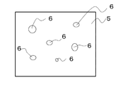
- FIG. 6 shows a partial schematic plan view of a conventional electrode.
- a recess 6 may be formed on the surface of the protective layer 5.
- the concave portion 6 is a portion where the active material layer is exposed or a portion where the thickness of the protective layer 5 is extremely thin. It is inferred that the recess 6 formed on the surface of the protective layer 5 is caused by the particles constituting the protective layer 5 entering the voids formed between the active materials in the active material layer.
- the protective effect of the active material layer by the protective layer is reduced.
- a protective layer provided on the surface of the negative electrode active material layer in the lithium ion secondary battery has a concave portion having a diameter of several ⁇ m to several tens of ⁇ m, for example, the lithium ion secondary battery has a concave portion at the time of charge / discharge. Current concentration occurs and Li is deposited. If Li is deposited in the recess, an internal short circuit of the lithium ion secondary battery may occur through the Li.
- an electrode for a power storage device in which a protective layer is formed as uniformly as possible is desired.
- An object of the present invention is to suppress the formation of recesses in a protective layer containing particles provided on an active material layer.
- the active material layer is protected by biasing the active material layer binding agent to the surface side of the active material layer in the thickness direction of the active material layer on which the protective layer is disposed. It has been found that recesses are less likely to be formed in the layer.
- the electrode for the power storage device of the present invention is disposed on the surface of the current collector, the active material layer disposed on the surface of the current collector, including the active material and the binder for the active material layer, and the surface of the active material layer
- a protective layer containing insulating particles, and of the active material layer, the protective layer side from the center in the thickness direction is the surface side portion, and the remaining current collector side is the current collector side portion.
- the deviation index indicating the deviation in the thickness direction of the binder for the active material layer is a ratio of the content concentration of the binder for the active material layer in the surface side portion to the content concentration of the binder for the active material layer in the current collector side portion.
- the bias index in the active material layer is greater than 1.
- the insulating particles are preferably ceramic particles.
- an active material layer slurry containing an active material, a binder for an active material layer, and a first solvent is applied to the surface of a current collector.
- Slurry coating process for active material layer to be formed active material layer forming process for forming active material layer by heating and drying slurry layer for active material layer, binding of insulating particles and protective layer on the surface of active material layer
- the active material layer has the surface side of the active material layer relative to the center in the thickness direction as the surface side portion, and the remaining current collector side as the current collector side portion.
- the power storage device according to the present invention includes the power storage device electrode obtained by the method for manufacturing the power storage device electrode or the power storage device electrode.
- the formation of a recess in the protective layer is suppressed.
- the electrode for a power storage device of the present invention can be easily manufactured.
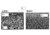
- FIG. 3 is an observation result of a cross section of a lithium ion secondary battery electrode of Example 1 with a scanning electron microscope (hereinafter referred to as SEM).
- SEM scanning electron microscope
- FIG. 2 It is a SEM observation result of the cross section of the electrode for lithium ion secondary batteries of the comparative example 1.
- Electrode for power storage device the electrode for lithium ion secondary batteries is demonstrated as an example of the electrode for electrical storage apparatuses of this invention.
- the electrode for a lithium ion secondary battery includes a current collector, an active material layer, and a protective layer.
- a current collector refers to a chemically inert electronic high conductor that keeps a current flowing through an electrode during discharge or charging of a lithium ion secondary battery.
- the material of the current collector at least one selected from silver, copper, gold, aluminum, tungsten, cobalt, zinc, nickel, iron, platinum, tin, indium, titanium, ruthenium, tantalum, chromium, molybdenum, and stainless steel Examples of such a metal material can be given.
- the current collector may be covered with a known protective layer. You may use the processed electrical power collector which performed the some process on the surface of the electrical power collector by the well-known method as an electrical power collector.
- the current collector can take the form of a foil, a sheet, a film, a linear shape, a rod shape, a mesh, or the like. Therefore, for example, a metal foil such as a copper foil, a nickel foil, an aluminum foil, and a stainless steel foil can be suitably used as the current collector.
- a metal foil such as a copper foil, a nickel foil, an aluminum foil, and a stainless steel foil can be suitably used as the current collector.
- the thickness is preferably in the range of 1 ⁇ m to 100 ⁇ m.
- the active material layer is disposed on the surface of the current collector and includes an active material and a binder for the active material layer.
- the active material layer may further contain a conductive additive.
- a positive electrode active material a solid solution composed of a spinel such as LiMn 2 O 4 and a mixture of a spinel and a layered compound, LiMPO 4 , LiMVO 4 or Li 2 MSiO 4 (wherein M is Co, Ni, Mn, Selected from at least one of Fe) and the like.
- LiMPO 4 F M is a transition metal
- LiMBO 3 such LiFeBO 3 (M is a transition metal
- Any metal oxide used as the positive electrode active material may be based on the above composition formula.
- the positive electrode active material a metal oxide obtained by substituting a metal element contained in the basic composition with another metal element can also be used.
- a positive electrode active material that does not contain lithium ions contributing to charge / discharge for example, sulfur alone (S), a compound in which sulfur and carbon are combined, a metal sulfide such as TiS 2 , V 2 O, etc. 5 , oxides such as MnO 2 , polyaniline and anthraquinone, compounds containing these aromatics in the chemical structure, conjugated materials such as conjugated diacetic acid organic materials, and other known materials can also be used.
- a compound having a stable radical such as nitroxide, nitronyl nitroxide, galvinoxyl, phenoxyl, etc. may be adopted as the positive electrode active material.
- a positive electrode active material that does not contain lithium it is necessary to add lithium ions to the positive electrode and / or the negative electrode in advance by a known method.
- the positive electrode active material is preferably in the form of a powder, and the average particle diameter D 50 of the powder is preferably 1 ⁇ m to 20 ⁇ m.
- the average particle diameter D 50 of the positive electrode active material is too small, there is a possibility to increase the reaction area of the positive electrode active material and the electrolyte by increasing the specific surface area of the cathode active material. Therefore, decomposition of the electrolytic solution proceeds and the cycle characteristics of the lithium ion secondary battery may be deteriorated.
- the average particle diameter D 50 of the positive electrode active material is too large resistance of the lithium ion secondary battery increases, there is a possibility that the output characteristics of the lithium ion secondary battery decreases.
- the average particle size D 50 can be measured by a laser diffraction particle size distribution measuring method.
- the average particle diameter D 50 is that the particle size cumulative value of the volume distribution in the particle size distribution measurement by laser diffraction method is equivalent to 50%. That is, the average particle diameter D 50 means the median size measured by volume.
- the negative electrode active material a material capable of inserting and extracting lithium ions can be used.
- the negative electrode active material include a simple substance, an alloy, or a compound that can occlude and release lithium ions.
- the negative electrode active material include Li, group 14 elements such as carbon, silicon, germanium, and tin, group 13 elements such as aluminum and indium, group 12 elements such as zinc and cadmium, group 15 elements such as antimony and bismuth, An alkaline earth metal such as magnesium or calcium, or a group 11 element such as silver or gold may be used alone. Since one silicon atom reacts with a plurality of lithiums, silicon becomes a high-capacity active material.
- silicon has a possibility that the expansion and contraction of the volume become remarkable with the insertion and extraction of lithium.
- an alloy or compound in which other elements such as a transition metal are combined with silicon alone as the negative electrode active material.
- the alloy or compound include tin-based materials such as Ag—Sn alloy, Cu—Sn alloy and Co—Sn alloy, carbon-based materials such as various graphites, SiO x (disproportionated into silicon simple substance and silicon dioxide). Examples thereof include silicon-based materials such as 0.3 ⁇ x ⁇ 1.6), silicon alone, or composites obtained by combining silicon-based materials and carbon-based materials.
- the carbon-based material examples include non-graphitizable carbon, artificial graphite, natural graphite, cokes, graphites, glassy carbons, organic polymer compound fired bodies, carbon fibers, activated carbon, and carbon blacks.
- the organic polymer compound fired body refers to a material obtained by firing and carbonizing a polymer material such as phenols and furans at an appropriate temperature.
- M Co Nitride represented by Ni, Cu
- the negative electrode active material one or more of the above simple substances, alloys or compounds can be used.
- the negative electrode active material is preferably in powder form.
- the average particle diameter D 50 of the negative electrode active material is preferably 0.1 ⁇ m or more and 40 ⁇ m or less, and more preferably 1 ⁇ m or more and 30 ⁇ m or less.
- the average particle diameter D 50 of the negative electrode active material is too small, the increase in the specific surface area of the anode active material, there is a possibility that the contact area between the negative electrode active material and the electrolyte solution increases. Therefore, decomposition of the electrolytic solution proceeds and the cycle characteristics of the lithium ion secondary battery may be deteriorated. If the average particle diameter D 50 of the negative electrode active material is too large, if the conductivity using a low negative electrode active material, conductive entire electrode becomes uneven, lowering the charge and discharge characteristics of the lithium ion secondary battery There is a risk.
- the binder for the active material layer plays a role of tying the active material and, if necessary, the conductive assistant to the current collector.
- binder for the active material layer examples include fluorine-containing resins such as polyvinylidene fluoride, polytetrafluoroethylene, and fluororubber, thermoplastic resins such as polypropylene and polyethylene, imide resins such as polyimide and polyamideimide, and poly (meth).
- fluorine-containing resins such as polyvinylidene fluoride, polytetrafluoroethylene, and fluororubber
- thermoplastic resins such as polypropylene and polyethylene
- imide resins such as polyimide and polyamideimide
- poly (meth) examples include acrylic resins such as acrylic acid, alkoxysilyl group-containing resins, styrene-butadiene rubber (hereinafter referred to as SBR), and carboxymethyl cellulose (hereinafter referred to as CMC).
- SBR alkoxysilyl group-containing resins
- CMC carboxymethyl cellulose
- Active material: Binder for active material layer 1: 0.005 to 1: 0.2 is more preferable, and 1: 0.01 to 1: 0.15 is more preferable. If the binder for the active material layer is too small, the moldability of the electrode may be lowered, and if the binder for the active material layer is too much, the energy density of the electrode may be lowered.
- Conductive aid is added to increase the conductivity of the electrode.
- the conductive auxiliary agent may be optionally added when the electrode conductivity is insufficient, and may not be added when the electrode conductivity is sufficiently excellent.
- As the conductive assistant a chemically inert electronic high conductor is used. Examples of the conductive assistant include carbon black, graphite, acetylene black, ketjen black (registered trademark), vapor grown carbon fiber (Vapor Grown Carbon Fiber: VGCF), and various metal particles. . These conductive assistants can be added to the active material layer alone or in combination of two or more.
- the density of the active material layer is preferably 1.0 g / cm 3 or more and 1.8 g / cm 3 or less, more preferably 1.2 g / cm 3 or more and 1.6 g / cm 3 or less. it is further preferred 3 g / cm 3 or more 1.5 g / cm 3 or less.
- the density of the active material layer here is calculated from the equation of mass of active material layer (g) / (active material layer thickness (cm) ⁇ active material layer area (cm 2 )). If the density of the active material layer is too high, the electrolyte periphery may be reduced, and the life may be reduced. If the density of the active material layer is too low, the energy density of the battery may be reduced.
- the thickness of the active material layer is preferably 60 ⁇ m to 90 ⁇ m, more preferably 65 ⁇ m to 85 ⁇ m, and still more preferably 70 ⁇ m to 80 ⁇ m. If the thickness of the active material layer is too thick, there is a risk that the insertion and extraction of lithium ions into the active material in the active material layer may not be performed uniformly in the depth direction. If the thickness of the active material layer is too thin, The proportion of the active material layer in the battery becomes small, and the energy density of the lithium ion secondary battery may be reduced.
- the porosity of the active material layer is preferably 27% to 50%, more preferably 31% to 43%, and still more preferably 34% to 40%.
- the porosity of the active material layer can be calculated by the following formula.
- the occupied volume ratio (volume%) of the active material in the active material layer is preferably 50 volume% or more and 70 volume% or less when the volume of the active material layer is 100 volume%, and is 55 volume% or more and 65 volume%. More preferably, it is 58 volume% or more and 62 volume% or less.
- the volume ratio of the active material in the active material layer is the ratio of the volume of the active material to the apparent volume of the active material layer. Specifically, the occupied volume ratio of the active material can be calculated by the following formula.
- the apparent volume of the active material layer the basis weight of the active material layer / the density of the active material layer If the occupied volume ratio of the active material is too large, the adhesiveness of the electrode may be lowered and the moldability may be deteriorated. When the occupied volume ratio of the active material is too small, the energy density of the battery may be lowered.
- the protective layer side from the center in the thickness direction is the surface side portion
- the remaining current collector side is the current collector side portion
- the thickness direction of the binder for the active material layer in the active material layer is the ratio of the content concentration of the binder for the active material layer on the surface side portion to the content concentration of the binder for the active material layer on the current collector side portion. The index is greater than 1.
- the bias index in the active material layer is expressed by the following formula.
- Bias index in active material layer concentration of binder for active material layer on surface side / concentration of binder for active material layer on current collector side
- the bias index in the active material layer is larger than 1, it indicates that the binder for the active material layer is contained more in the surface side portion than in the current collector side portion.
- production of the recessed part of a protective layer can be suppressed because the surface side part contains the binder for active material layers more than the collector side part.
- bias index in the active material layer is too large, the binder for the active material layer on the side of the current collector becomes too small, and the active material may not be favorably bound to the current collector.
- the bias index in the active material layer is preferably smaller than 2.
- the protective layer side is the outermost surface side portion from the center in the thickness direction
- the remaining current collector side is the middle surface side portion
- the deviation in the thickness direction of the binder for the active material layer on the surface side portion is The second bias index is preferably larger than 1.
- the second bias index at the surface side is expressed by the following formula.
- 2nd bias index in the surface side portion concentration of the binder for the active material layer in the outermost surface side portion / concentration of the binder for the active material layer in the middle surface side portion
- the second bias index in the surface side portion is larger than 1, it indicates that the binder for the active material layer is contained more in the outermost surface side portion than in the middle surface side portion.
- production of the recessed part of a protective layer can be suppressed more because the outermost surface side part contains the binder for active material layers more than the middle surface side part.
- concentration of the binder for active material layers in an active material layer is not specifically limited, For example, the following method is employable.
- an element contained in the binder for the active material layer is measured with an electron beam probe microanalyzer (EPMA), and the distribution of the binder for the active material layer in the cross section is mapped. Based on this map, the concentration of the binder for the active material layer in the surface side portion and the current collector side portion is quantified, and the bias index is calculated.
- EPMA electron beam probe microanalyzer
- fluorine mapping may be performed.
- the active material layer is dyed with bromine (Br), bromine is attached to the binder for active material layer, and the binder for active material layer is bonded. Mapping of bromine adhering to the adsorbent may be performed.
- osmium may be dyed with osmium (Os) instead of bromine and attached to the active material layer binder, and the osmium attached to the active material layer binder may be mapped.
- the surface of the current collector can be formed using a conventionally known method such as a roll coating method, a dip coating method, a doctor blade method, a spray coating method, or a curtain coating method. What is necessary is just to apply
- an active material layer-forming composition containing an active material, an active material layer binder and, if necessary, a conductive aid is prepared, and an appropriate solvent is added to the active material layer-forming composition.
- a slurry for the active material layer is obtained.
- the binder for active material layer may be used as a solution in which the binder for active material layer is dissolved in a solvent in advance or as a dispersed suspension. Examples of the solvent include N-methyl-2-pyrrolidone (hereinafter referred to as NMP), methanol, methyl isobutyl ketone (hereinafter referred to as MIBK), and water.
- NMP N-methyl-2-pyrrolidone
- MIBK methyl isobutyl ketone
- the active material layer slurry is applied to the current collector by a known method, and the current collector coated with the active material layer slurry is heated and dried to form an active material layer on the current collector.
- the method for forming the active material layer so that the bias index in the active material layer is greater than 1 is not particularly limited.
- it can be formed by preparing a plurality of active material layer slurries with different binder contents and applying the active material layer slurries in several layers. For example, apply an active material layer slurry with a low content of the active material layer binder to the current collector, and apply an active material layer slurry with a high content of the active material layer binder thereon. That's fine.
- the active material layer when the current collector coated with the slurry for active material layer is heated and dried, the active material layer may be formed so that the bias index in the active material layer is larger than 1 by adjusting the heating and drying conditions. it can.
- the component having the lowest specific gravity is generally the binder for the active material layer.
- the solvent contained in the active material layer slurry is evaporated from the surface side of the active material layer slurry.
- the solvent in the active material layer slurry moves to the surface side.
- the binder for the active material layer having the smallest specific gravity is likely to move to the surface side as the solvent moves, as compared with the other components contained. Therefore, the binder for active material layer can be moved to the surface side so that the bias index in the active material layer becomes larger than 1 by adjusting the heating and drying conditions.
- the heating and drying conditions may be adjusted so that the drying speed of the solvent is increased.
- Heat drying may be performed under normal pressure conditions or under reduced pressure conditions using a vacuum dryer.
- the heat drying may be performed under one heat drying condition, or may be performed by appropriately combining a plurality of heat drying conditions.
- the heating and drying temperature may be set as appropriate, and the heating and drying time may be set as appropriate according to the coating amount and the heating and drying temperature.
- heating for curing the binder may be performed.
- the active material layer may be compressed after the active material layer is formed by heat drying.
- the method for forming the active material layer so that the second bias index on the surface side portion is greater than 1 is not particularly limited.
- a method of forming the active material layer so that the second bias index in the surface side portion is greater than 1 the same method as the method of forming the active material layer so that the bias index in the active material layer is greater than 1 described above Is applicable.
- the protective layer is disposed on the surface of the active material layer and includes insulating particles.
- the protective layer may further contain a binder for the protective layer.
- the insulating particles include insulating inorganic particles and insulating organic particles.
- the insulating particles only inorganic particles or only organic particles may be used, or inorganic particles and organic particles may be used in combination. If only inorganic particles are used as the insulating particles, the heat resistance of the protective layer is increased. In addition, by including organic particles in the insulating particles, the protective layer can have a function of shutting down the battery at a set temperature.
- the insulating inorganic particles include ceramic particles.
- ceramic particles oxides, nitrides and carbides are desirable.
- Specific examples of the ceramic particles include Al 2 O 3 , SiO 2 , TiO 2 , ZrO 2 , MgO, SiC, AlN, BN, talc, mica, kaolinite, CaO, ZnO, and zeolite.
- Al 2 O 3 , SiO 2 , and TiO 2 are preferable from the viewpoint of easy availability, and Al 2 O 3 is particularly preferable.
- insulating organic particles examples include polytetrafluoroethylene (PTFE) particles, polyethylene (PE) particles, polypropylene (PP) particles, polyester particles, polyamide particles, polymethyl methacrylate (PMMA) particles, and ethylene / acrylic acid co-polymers.
- PTFE polytetrafluoroethylene
- PE polyethylene
- PP polypropylene
- polyester particles polyester particles
- polyamide particles polymethyl methacrylate particles
- PMMA polymethyl methacrylate
- ethylene / acrylic acid co-polymers examples include polytetrafluoroethylene (PTFE) particles, polyethylene (PE) particles, polypropylene (PP) particles, polyester particles, polyamide particles, polymethyl methacrylate (PMMA) particles, and ethylene / acrylic acid co-polymers.
- PMMA polymethyl methacrylate
- EA Polymer (EA) particles, polyvinyl chloride particles, polyurethane particles, tetrafluoroethylene / perfluoroalkyl vinyl ether copolymer (PFA) particles, tetrafluoroethylene / hexafluoropropylene copolymer (FEP) particles, tetrafluoroethylene / Examples include ethylene copolymer (ETFE) particles, polyvinylidene fluoride (PVDF) particles, and polychlorotrifluoroethylene (PCTFE) particles.
- PFA perfluoroalkyl vinyl ether copolymer
- FEP tetrafluoroethylene / hexafluoropropylene copolymer
- EA tetrafluoroethylene / Examples include ethylene copolymer (ETFE) particles, polyvinylidene fluoride (PVDF) particles, and polychlorotrifluoroethylene (PCTFE) particles.
- the average particle diameter D 50 of the insulating particles is less than the average particle diameter D 50 of the active material to be used.
- the insulating particles is easily disposed along the unevenness of the surface of the active material layer, active on the surface of the active material layer
- the surface of the substance is easily covered with a protective layer containing insulating particles. If the surface of the active material is coated with a protective layer, the active material can be prevented from coming into direct contact with the electrolytic solution, and the electrolytic solution can be prevented from being decomposed by the active material.
- the average particle size D 50 of the insulating particles is 100nm or more 1 ⁇ m or less, and more preferably 200nm or more 700nm or less.
- the average particle diameter D 50 of the insulating particles is too large, there is a possibility that the thickness of the protective layer is greater than the desired thickness.
- the smaller the average particle diameter D 50 of the insulating particles tends to densely fill the insulating particles in the protective layer, the filling of the insulating particles in the protective layer is increased.
- the higher the filling property of the protective layer the higher the effect of protecting the active material layer.
- the thickness of the protective layer is preferably 1 ⁇ m or more and 15 ⁇ m or less, and more preferably 4 ⁇ m or more and 8 ⁇ m or less. If the thickness of the protective layer is too thick, the battery resistance may increase, and if the thickness of the protective layer is too thin, it may be difficult to protect the active material layer well.
- the same binder as that for the active material layer can be used.
- the protective layer binder may be the same type as the active material layer binder, or may be a different type.
- the method for disposing the protective layer on the active material layer is not particularly limited.
- the protective layer can be disposed on the active material layer by the following method. Insulating particles and, if necessary, the binder for the protective layer are dissolved in an organic solvent or water to prepare a solution-like or paste-like mixture.
- a protective layer can be formed on the active material layer by applying the mixture onto the active material layer and then drying by heating to volatilize and remove the organic solvent or water.
- a coating method a conventionally known method such as a roll coating method, a dip coating method, a doctor blade method, a curtain coating method, or a spray coating method may be used.
- the organic solvent ethanol, NMP, methanol, MIBK, or the like can be used.
- the water is preferably water from which impurities have been removed, such as distilled water or ion exchange water.
- the insulating particles are organic particles, particularly fluororesin-based organic particles
- a dispersion in which the organic particles are dispersed in a propellant composed of chlorofluorocarbons and / or propane onto the surface of the active material layer A protective layer containing organic particles can be easily formed on the surface of the active material layer.
- the fluororesin has binding properties.
- spraying the fluororesin-based organic particles together with the spray onto the active material layer the fluororesin-based organic particles can be favorably bound to the active material layer.
- the propellant mists when sprayed and does not remain in the protective layer. For this reason, a step of removing the propellant such as a drying step is unnecessary.
- a thinner protective layer can be formed.
- propellant examples include perfluorocarbon, fluorocarbon, hydrogen-containing chlorofluorocarbon, or a mixture thereof.
- propellant specifically, hydrofluoroalkane, 1,1,1,2-tetrafluoroethane, 1,1,1,2,3,4,4,5,5,5 decafluoropentane, 1, 1, 2, 3, 3, 3-heptafluoro-n-propane or mixtures thereof.
- the protective layer Since the bias index in the active material layer is greater than 1, the protective layer is unlikely to have a recess. When the second bias index in the surface side portion is larger than 1, further, the protective layer is less likely to be depressed.
- the following reason can be considered as one of the reasons why the concave portion of the protective layer is generated.
- the binder for the active material layer is biased on the surface side of the active material layer. It is presumed that the voids on the surface of the active material layer are reduced by filling the voids on the surface of the active material layer with the binder for the active material layer that is biased to the surface side. It is considered that when the voids on the surface of the active material layer are reduced, the insulating particles entering the voids are reduced, and the recesses are less likely to be formed in the protective layer.
- FIG. 1 is a schematic diagram illustrating an electrode for a power storage device according to this embodiment.
- an active material 2 is bound on a current collector 1 by a binder 3 for an active material layer.
- An active material layer 4 is formed from the active material 2 and the active material layer binder 3.
- a protective layer 5 is disposed on the active material layer 4.
- the active material layer binder 3 is present more on the surface side than the center of the active material layer 4 in the thickness direction, and less on the current collector side than the center of the active material layer 4 in the thickness direction.
- the protective layer 5 includes insulating particles 51 and a protective layer binder 52.
- the insulating particles 51 and the protective layer binder 52 are arranged along the surface irregularities of the active material 2 and the active material layer binder 3.
- the protective layer 5 uniformly and uniformly covers the entire active material layer 4, and the protective layer 5 does not have a defect portion, that is, a recess.
- the active material layer 4 Since the active material layer 4 is covered with the protective layer 5, the active material 2 is not in direct contact with the electrolytic solution or the like. Therefore, the decomposition reaction of the electrolytic solution that easily occurs due to the active material near the electrode surface is suppressed. Moreover, if a recessed part is not formed in the protective layer provided in the surface of the negative electrode active material layer, Li will not precipitate in the recessed part. Therefore, the internal short circuit of the lithium ion secondary battery through Li can be suppressed.
- the method for manufacturing an electrode for a power storage device of the present invention includes an active material layer slurry applying step, an active material layer forming step, and a protective layer forming step.
- an active material layer slurry layer containing an active material, an active material layer binder, and a first solvent is applied to the surface of the current collector to form an active material layer slurry layer.
- Examples of the first solvent include NMP, methanol, MIBK, and water.
- a method for applying the slurry for the active material layer a conventionally known method such as a roll coating method, a dip coating method, a doctor blade method, a curtain coating method, or a spray coating method may be used.
- the active material layer slurry layer is heated and dried to form an active material layer.
- the active material layer binding agent for the active material layer in the active material layer with the surface side of the active material layer as the surface side portion and the current collector side as the current collector side portion from the center in the thickness direction of the active material layer
- the active material Heat drying conditions are adjusted so that the bias index in the layer is greater than 1.
- the heating and drying conditions may be adjusted so that the drying speed of the solvent is increased.
- the drying speed of the solvent in the slurry layer for active material layer is increased, the binder for active material layer easily follows the solvent that moves to the surface side of the active material layer.
- increase the heating drying temperature increase the amount of hot air for drying, increase the blowing speed of hot air for drying, change the blowing direction of hot air for drying
- the method of adjusting can be adopted.
- As adjustment of heat drying conditions it is more preferable to raise heat drying temperature.
- the heat drying temperature here refers to the temperature in the drying furnace.
- the heating and drying temperature conditions are usually dried at a temperature of about 80 ° C. to 85 ° C. to remove water, but dried at a temperature of about 120 ° C. to 125 ° C. Is preferably removed.
- the solvent is NMP, it is usually dried at a temperature of about 90 ° C. to 150 ° C. to remove NMP, but it is preferably dried at a temperature of about 200 ° C. to 230 ° C. to remove NMP.
- heating may be further performed in order to sufficiently cure the binder for the active material layer.
- heating may be further performed in order to sufficiently cure the binder for the active material layer.
- the method for manufacturing an electrode for a power storage device of the present invention may include a compression step of compressing the current collector and the active material layer together after the active material layer formation step in order to increase the density of the active material layer.
- a protective layer containing insulating particles is formed on the surface of the active material layer.
- the protective layer forming step when the insulating particles are organic particles, a spraying step of spraying a dispersion in which organic particles are dispersed in a propellant composed of chlorofluorocarbons and / or propane onto the surface of the active material layer can be mentioned.
- a protective layer formation process having a protective layer slurry application
- a protective layer slurry layer is formed by applying a protective layer slurry containing insulating particles, a protective layer binder and a second solvent to the surface of the active material layer.
- the same solvent as the first solvent can be used as the second solvent.
- the second solvent and the first solvent may be the same type or different types.
- the protective layer slurry layer is heated and dried to form a protective layer.
- the heat drying conditions for the protective layer slurry layer are not particularly limited. Heat drying may be performed at a temperature and time suitable for evaporating the second solvent and curing the binder for the protective layer.
- the method for producing an electrode for a power storage device of the present invention may include a heating step of further curing both the active material layer binder and the protective layer binder after the protective layer forming step.
- heating may be performed at a temperature equal to or higher than the curing temperature of the binder for the active material layer and the binder for the protective layer.
- the method for manufacturing an electrode for a power storage device of the present invention may include a compression step of compressing the protective layer, the active material layer, and the current collector together after the protective layer forming step in order to increase the density of the protective layer. Good.
- the power storage device electrode can be more easily manufactured.
- a power storage device includes the electrode for a power storage device.
- the power storage device of the present invention include a secondary battery and a capacitor.
- the power storage device of the present invention is preferably a lithium ion secondary battery or a lithium ion capacitor.
- the power storage device of the present invention is preferably a lithium ion secondary battery.
- the power storage device of the present invention is characterized by its electrodes. As other components constituting the power storage device, known components suitable for each power storage device can be used.
- the power storage device of the present invention has the above-described power storage device electrode as at least one of a positive electrode and a negative electrode. A known electrode can be used as the other electrode when the power storage device electrode of the present invention is used only for the negative electrode or the positive electrode.
- a separator is sandwiched between a positive electrode and a negative electrode to form an electrode body.
- the electrode body may be either a stacked type in which a positive electrode, a separator and a negative electrode are stacked, or a wound type in which a positive electrode, a separator and a negative electrode are sandwiched.
- an electrolytic solution is added to the electrode body to form a lithium ion secondary battery.
- the lithium ion secondary battery should just be charged / discharged in the voltage range suitable for the kind of active material contained in an electrode.
- the shape of the lithium ion secondary battery is not particularly limited, and various shapes such as a cylindrical shape, a square shape, a coin shape, and a laminate shape can be adopted.
- a lithium ion secondary battery has the above electrode for a power storage device.
- the active material layer is uniformly coated with the protective layer. Therefore, the electrode is satisfactorily protected by the protective layer in the lithium ion secondary battery.
- the lithium ion secondary battery includes an electrolyte and, if necessary, a separator in addition to the above-described electrode for a power storage device as a battery component.
- Electrolyte contains movable lithium ions.
- a non-aqueous electrolyte can be used as the electrolyte.
- the nonaqueous electrolytic solution contains an organic solvent and an electrolyte salt dissolved in the organic solvent.
- cyclic esters examples include ethylene carbonate, propylene carbonate, butylene carbonate, gamma butyrolactone, vinylene carbonate, 2-methyl-gamma butyrolactone, acetyl-gamma butyrolactone, and gamma valerolactone.
- chain esters include dimethyl carbonate, diethyl carbonate, dibutyl carbonate, dipropyl carbonate, ethyl methyl carbonate, propionic acid alkyl ester, malonic acid dialkyl ester, and acetic acid alkyl ester.
- ethers examples include tetrahydrofuran, 2-methyltetrahydrofuran, 1,4-dioxane, 1,2-dimethoxyethane, 1,2-diethoxyethane, and 1,2-dibutoxyethane.
- Examples of the electrolyte salt dissolved in the organic solvent include lithium salts such as LiClO 4 , LiAsF 6 , LiPF 6 , LiBF 4 , LiCF 3 SO 3 , and LiN (CF 3 SO 2 ) 2 .
- lithium salt such as LiClO 4 , LiPF 6 , LiBF 4 , LiCF 3 SO 3 is added in an organic solvent such as ethylene carbonate, dimethyl carbonate, propylene carbonate, and diethyl carbonate to 0.5 mol / l to 2 mol / l.
- organic solvent such as ethylene carbonate, dimethyl carbonate, propylene carbonate, and diethyl carbonate to 0.5 mol / l to 2 mol / l.
- a solution dissolved at a concentration of about 1 is mentioned.
- the separator separates the positive electrode and the negative electrode and allows lithium ions to pass through while preventing a short circuit of current due to contact between the two electrodes.
- a porous membrane and a nonwoven fabric are mentioned, for example.
- the material for the porous film include synthetic resins such as polytetrafluoroethylene, polypropylene, and polyethylene, natural polymers such as cellulose, and ceramics.
- the material for the nonwoven fabric include synthetic resins such as polytetrafluoroethylene, polypropylene, and polyethylene, and natural polymers such as cellulose.
- the lithium ion capacitor is a combination of a negative electrode of a lithium ion secondary battery and a positive electrode of an electric double layer capacitor.
- the positive electrode of the lithium ion capacitor is charged and discharged by forming an electric double layer, and the negative electrode is charged and discharged by a lithium chemical reaction.
- the lithium ion capacitor of this invention has the electrode for electrical storage devices described above on the negative electrode.
- the positive electrode of a lithium ion capacitor has a conductor with a large surface area disposed on a current collector.
- Examples of the conductor having a large surface area include activated carbon and polyacene compounds.
- the positive electrode may contain a binder for binding such a conductor having a large surface area, and may further contain a conductive additive.
- the power storage device of the present invention may be mounted on a vehicle.
- the vehicle may be a vehicle that uses electric energy from the power storage device for all or a part of its power source.
- a lithium ion secondary battery When a lithium ion secondary battery is mounted on a vehicle, a plurality of lithium ion secondary batteries may be connected in series to form an assembled battery.
- Examples of devices equipped with the power storage device include various home appliances driven by batteries such as personal computers and portable communication devices, office devices, and industrial devices in addition to vehicles.
- the power storage device of the present invention includes wind power generation, solar power generation, hydroelectric power generation, and other power system power storage devices and power smoothing devices, power for power sources such as ships, and / or power supply sources for auxiliary equipment, aircraft, spacecrafts, and the like.
- Power source for power and / or auxiliary equipment, auxiliary power source for vehicles not using electricity as a power source power source for mobile home robots, power source for system backup, power source for uninterruptible power supply, for electric vehicles You may use for the electrical storage apparatus which stores temporarily the electric power required for charge in a charging station.
- Example 1 First, 98 parts by mass of graphite powder having an average particle diameter D 50 of 20 ⁇ m as the negative electrode active material and 1 part by mass of SBR and 1 part by mass of CMC as the binder for the active material layer were mixed to obtain a mixture. This mixture was dispersed in an appropriate amount of ion-exchanged water to prepare an active material layer slurry. The slurry for active material layer was apply
- the current collector coated with the slurry for active material layer is conveyed at a conveyance speed of 3.0 m / min, and a first drying furnace having a heating and drying temperature of 120 ° C. and a second drying furnace having a heating and drying temperature of 125 ° C. And an active material layer was formed on the current collector.
- the drying time in each drying furnace was about 1 to 2 minutes.
- the current collector and the active material layer on the current collector were firmly and closely joined with a roll press machine to produce a joined product.
- the density of the negative electrode active material layer was 1.4 g / cm 3 .
- the density of the negative electrode active material layer was calculated from the equation of mass (g) of negative electrode active material layer / (thickness of negative electrode active material layer (cm) ⁇ area of negative electrode active material layer (cm 2 )).
- the basis weight of the negative electrode active material layer was 11.1 mg / cm 2 .
- the porosity of the active material layer was 37%.
- the porosity was calculated from the following formula. Here, a unit area of 1 cm 2 was used.
- Apparent volume of active material layer per unit area active material layer basis weight ⁇ active material Layer density
- True density of graphite is 2.28 g / cm 3
- true density of CMC is 0.95 g / cm 3 and the true density of SBR were calculated as 1.6 g / cm 3 .
- the occupied volume ratio (volume%) of the active material in the active material layer was 60 volume% when the volume of the active material layer was 100 volume%.
- the occupied volume ratio of the active material in the active material layer was calculated by the following formula. Here, 1 cm 2 was used as the unit area.
- the apparent volume of the active material layer the basis weight of the active material layer / the density of the active material layer
- the true density of graphite was calculated as 2.28 g / cm 3 .
- alumina having an average particle diameter D 50 of 0.5 ⁇ m as insulating particles and 4 parts by mass of polyvinylidene fluoride (PVDF) as a binder for the protective layer were mixed to obtain a mixture.
- PVDF polyvinylidene fluoride
- This mixture was dispersed in an appropriate amount of NMP to prepare a slurry for the protective layer.
- the protective layer slurry was applied in a film form on the active material layer.
- the bonded article coated with the protective layer slurry was passed through a third drying furnace having a heating and drying temperature of 120 ° C. to form a protective layer on the active material layer.
- the drying time in the third drying furnace was 1 minute.
- the current collector in which the protective layer was formed on the active material layer was further heated at 120 ° C. for 6 hours with a vacuum dryer to produce the lithium ion secondary battery electrode of Example 1.
- the thickness of the active material layer of the electrode for the lithium ion secondary battery of Example 1 was 75 ⁇ m, and the thickness of the protective layer was 6 ⁇ m.
- Comparative Example 1 The conveying speed of the current collector coated with the slurry for the active material layer is 1.8 m / min, the heating drying temperature of the first drying furnace is 80 ° C., the heating drying temperature of the second drying furnace is 85 ° C.
- a lithium ion secondary battery electrode of Comparative Example 1 was produced in the same manner as the lithium ion secondary battery electrode of Example 1 except that the drying time in the furnace was about 2 to 3 minutes.
- the thickness of the active material layer of the electrode for the lithium ion secondary battery of Comparative Example 1 was 75 ⁇ m, and the thickness of the protective layer was 6 ⁇ m.
- Osmium osmium
- EPMA electron probe microanalyzer
- the measurement conditions of EPMA are: acceleration voltage: 15 kV, irradiation current: 30 nA, measurement time: 20 msec, beam size: 1 ⁇ m, data point: 240 ⁇ 212 to 223 points, area size: 120 ⁇ 106 to 111.5 ⁇ m, analytical X-ray Spectroscopic crystal: OsM ⁇ (6.44872 [A]) ⁇ PET.
- Example 2 The SEM observation result of Example 1 is shown in FIG. 2, and the SEM observation result of Comparative Example 1 is shown in FIG.
- the portion that appears white is the binder for active material layer.
- the concentration of the binder for the active material layer in the surface side portion and the current collector side portion was quantified, and the bias index in the active material layer was calculated.
- the bias index in the active material layer of Example 1 was 1.1
- the bias index in the active material layer of Comparative Example 1 was 0.8.
- the 2nd bias index in the surface side part of Example 1 was 1.3
- the 2nd bias index in the surface side part of the comparative example 1 was 0.9.
- the portion surrounded by the dotted line corresponds to the recess 6 shown in FIG. That is, the recess 6 shown in FIG. 6 is observed in the protective layer of Comparative Example 1.
- the insulating particles 51 exist on the entire surface of the electrode of Example 1, and the active material 2 was not observed. From this, it was found that in the electrode for the lithium ion secondary battery of Example 1, a protective layer was uniformly formed on the active material layer, and the protective layer had no recess. Therefore, it was found that by forming the bias index in the active material layer to be greater than 1, formation of the concave portion of the protective layer is dramatically suppressed.
- the lithium ion secondary battery electrode of Comparative Example 1 was extracted with a 0.95 cm 2 circular punch and used as an evaluation electrode.
- EC ethylene carbonate
- DEC diethyl carbonate
- a coin-type model battery (CR2032 type) was produced in a dry room using the solution dissolved so as to be an electrolyte.
- the coin-type model battery is manufactured by stacking a spacer, a lithium foil having a thickness of 500 ⁇ m as a counter electrode, a separator (trade name Celgard # 2400 manufactured by Celgard), and an evaluation electrode in this order, injecting an electrolytic solution, and then performing a caulking process. went.
- the model battery of Comparative Example 1 was charged with CCCV (constant current constant voltage) up to 3.95 V at a rate of 0.8 C at 25 ° C. Thereafter, the model battery of Comparative Example 1 was disassembled, and the surface of the electrode for the lithium ion secondary battery of Comparative Example 1 was observed with an SEM.
- CCCV constant current constant voltage
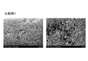
- FIG. 5 shows the SEM observation result of the concave portion of the electrode after charging of the model battery of Comparative Example 1.
- the right figure of FIG. 5 is an enlarged view of the left figure.
- a recess was observed in the protective layer on the surface of the electrode of Comparative Example 1.
- acicular Li was deposited in the recess as shown in FIG. That is, it was found that when a concave portion is generated in the protective layer, Li is deposited in the concave portion due to charge / discharge. If Li is deposited, the battery may be short-circuited through the deposited Li.
- the electrode for lithium ion secondary batteries of this invention Since it can suppress that a recessed part is formed in a protective layer, it turned out that the electrode for lithium ion secondary batteries of this invention has high safety
- the evaluation was made in the form of a lithium ion secondary battery, but it can be considered that the same can be said for the lithium ion secondary battery even if the form of the lithium ion capacitor is used.
Landscapes
- Engineering & Computer Science (AREA)
- Chemical & Material Sciences (AREA)
- Power Engineering (AREA)
- Chemical Kinetics & Catalysis (AREA)
- Electrochemistry (AREA)
- General Chemical & Material Sciences (AREA)
- Manufacturing & Machinery (AREA)
- Materials Engineering (AREA)
- Microelectronics & Electronic Packaging (AREA)
- Battery Electrode And Active Subsutance (AREA)
- Electric Double-Layer Capacitors Or The Like (AREA)
Abstract
粒子を含み、凹部の発生が抑制された保護層を活物質層上に設ける。 集電体と、集電体の表面に配置され、活物質と活物質層用結着剤とを含む活物質層と、活物質層の表面に配置され、絶縁性粒子を含む保護層とを備え、活物質層のうち、厚み方向の中央よりも保護層側を表面側部、残りの集電体側を集電体側部とし、活物質層における活物質層用結着剤の厚み方向の偏りを示す偏り指数を、表面側部における活物質層用結着剤の含有濃度の集電体側部における活物質層用結着剤の含有濃度に対する比としたときに、活物質層における偏り指数が1より大きいことを特徴とする。
Description
本発明は、蓄電装置用電極、蓄電装置及び蓄電装置用電極の製造方法に関する。
蓄電装置には二次電池とキャパシタがある。二次電池とキャパシタにおいて、電気二重層キャパシタとリチウムイオン二次電池ではその構造がほとんど同じである。蓄電装置は、一般に、主な構成要素として、正極、負極、セパレータ及び電解液を備える。
蓄電装置の一つであるリチウムイオン二次電池は、携帯電話や、電気自動車(EV:Electric Vehicle)などの様々な用途に用いられている。リチウムイオン二次電池に求められる特性として、高エネルギー密度化、サイクル特性および様々な動作環境での安全性などがある。
リチウムイオン二次電池は高温、高電圧使用環境下においても使用できることが要望されている。本明細書では4.3V以上の電圧で使用することを高電圧使用と定義する。しかしリチウムイオン二次電池を高温、高電圧で駆動させると、電池特性が悪化するという問題があった。
電池特性が悪化する原因として、高温、高電圧での駆動の場合、充電時に正極近傍で電解液の酸化分解が起こり、酸化分解により生じた酸などによって正極活物質などの金属成分が溶出することが挙げられる。正極活物質から金属成分が溶出すると、正極の容量が下がる。
高温、高電圧の使用環境下における電池特性を上げるために、正極、負極或いは両極に保護層を形成する検討が行われている。
特許文献1(特開2008-53207号公報)には、マグネシアを含む無機粒子からなるフィラー粒子とゴム性状高分子からなるバインダーとを含む保護層が正極活物質層の上に形成された正極が開示されている。
特許文献2(特開2006-48942号公報)には、正極又は負極の上に無機フィラーとバインダー溶液とを有する塗料を塗布して被覆層を形成する方法が開示されている。
基本的に、保護層が厚くなるほど、電池の内部抵抗が増大して、電池の充放電容量が低下する。また電池のエネルギー密度を高く維持するには、保護層の厚みはより薄い方が好ましい。
図6に従来の電極の部分概略平面模式図を示す。図6に模式的に示すように、粒子を含む保護層を薄くしようとすると、保護層5の表面に凹部6が形成されることがある。凹部6は、活物質層が露出している箇所、又は保護層5の厚さが極端に薄くなっている箇所である。保護層5の表面に形成される凹部6は、活物質層において活物質同士の間に生じる空隙に保護層5を構成する粒子が入り込むことによって生じると推察される。
保護層に凹部が存在すると、保護層による活物質層の保護効果は小さくなる。またリチウムイオン二次電池において負極活物質層の表面に設けられた保護層に、例えば、直径が数μm~数10μmのサイズの凹部が存在すると、リチウムイオン二次電池の充放電時にその凹部に電流集中が起こり、Liが析出する。Liが凹部に析出すると、そのLiを介してリチウムイオン二次電池の内部短絡が起こるおそれがある。
このことから、なるべく均一に保護層が形成された蓄電装置用電極が望まれている。
本発明は、活物質層上に設けた粒子を含む保護層において凹部の発生を抑制することを目的とする。
本発明者等が鋭意検討した結果、その表面に保護層が配置される活物質層の厚さ方向において、活物質層のうち当該表面側に活物質層用結着剤を偏らせることで保護層に凹部が形成されにくくなることを見いだした。
すなわち、本発明の蓄電装置用電極は、集電体と、集電体の表面に配置され、活物質と活物質層用結着剤とを含む活物質層と、活物質層の表面に配置され、絶縁性粒子を含む保護層と、を備え、活物質層のうち、厚み方向の中央よりも保護層側を表面側部、残りの集電体側を集電体側部とし、活物質層における活物質層用結着剤の厚み方向の偏りを示す偏り指数を、表面側部における活物質層用結着剤の含有濃度の集電体側部における活物質層用結着剤の含有濃度に対する比としたときに、活物質層における偏り指数が1より大きいことを特徴とする。
絶縁性粒子は、セラミックス粒子であることが好ましい。
本発明の蓄電装置用電極の製造方法は、集電体の表面に活物質、活物質層用結着剤及び第1溶媒を含む活物質層用スラリーを塗布して活物質層用スラリー層を形成する活物質層用スラリー塗布工程と、活物質層用スラリー層を加熱乾燥させて活物質層を形成する活物質層形成工程と、活物質層の表面に絶縁性粒子、保護層用結着剤及び第2溶媒を含む保護層用スラリーを塗布して保護層用スラリー層を形成する保護層用スラリー塗布工程と、保護層用スラリー層を加熱乾燥させて保護層を形成する保護層形成工程と、を有し、活物質層形成工程において、活物質層のうち厚み方向の中央よりも活物質層の表面側を表面側部、残りの集電体側を集電体側部とし、活物質層における活物質層用結着剤の厚み方向の偏りを示す偏り指数を、表面側部における活物質層用結着剤の含有濃度の集電体側部における活物質層用結着剤の含有濃度に対する比としたときに、活物質層における偏り指数が1より大きくなるように加熱乾燥条件を調整することを特徴とする。
本発明の蓄電装置は、上記蓄電装置用電極又は上記蓄電装置用電極の製造方法により得られた蓄電装置用電極を有することを特徴とする。
本発明の蓄電装置用電極において、保護層に凹部が生じることが抑制される。
本発明の蓄電装置用電極の製造方法によれば、容易に本発明の蓄電装置用電極を製造することができる。
<蓄電装置用電極>
以下に、本発明の蓄電装置用電極の一例としてリチウムイオン二次電池用電極を説明する。
以下に、本発明の蓄電装置用電極の一例としてリチウムイオン二次電池用電極を説明する。
リチウムイオン二次電池用電極は、集電体と、活物質層と、保護層とを備える。
集電体は、リチウムイオン二次電池の放電又は充電の間、電極に電流を流し続けるための化学的に不活性な電子高伝導体をいう。集電体の材料としては、銀、銅、金、アルミニウム、タングステン、コバルト、亜鉛、ニッケル、鉄、白金、錫、インジウム、チタン、ルテニウム、タンタル、クロム、モリブデンから選ばれる少なくとも一種、並びにステンレス鋼などの金属材料を例示することができる。集電体は公知の保護層で被覆されていてもよい。公知の方法で集電体の表面に何らかの処理を施した処理済み集電体を集電体として用いても良い。
集電体は箔、シート、フィルム、線状、棒状、メッシュなどの形態をとることができる。そのため、集電体として、例えば、銅箔、ニッケル箔、アルミニウム箔、ステンレス箔などの金属箔を好適に用いることができる。集電体が箔、シート、フィルム形態の場合は、その厚みが1μm~100μmの範囲内であることが好ましい。
活物質層は、集電体の表面に配置され、活物質と活物質層用結着剤とを含む。活物質層は更に導電助剤を含んでもよい。
正極活物質としては、例えば、層状化合物のLiaNibCocMndDeOf(0.2≦a≦1.2、b+c+d+e=1、0≦e<1、DはLi、Fe、Cr、Cu、Zn、Ca、Mg、S、Si、Na、K、Al、Zr、Ti、P、Ga、Ge、V、Mo、Nb、W、Laから選ばれる少なくとも1の元素、1.7≦f≦2.1)、Li2MnO3が挙げられる。また、正極活物質として、LiMn2O4等のスピネル、及びスピネルと層状化合物の混合物で構成される固溶体、LiMPO4、LiMVO4又はLi2MSiO4(式中のMはCo、Ni、Mn、Feのうちの少なくとも一種から選択される)などで表されるポリアニオン系化合物が挙げられる。さらに、正極活物質として、LiFePO4FなどのLiMPO4F(Mは遷移金属)で表されるタボライト系化合物、LiFeBO3などのLiMBO3(Mは遷移金属)で表されるボレート系化合物が挙げられる。正極活物質として用いられるいずれの金属酸化物も上記の組成式を基本組成とすればよい。正極活物質として、基本組成に含まれる金属元素を他の金属元素で置換した金属酸化物も使用可能である。また、正極活物質として、充放電に寄与するリチウムイオンを含まない正極活物質材料、たとえば、硫黄単体(S)、硫黄と炭素を複合化した化合物、TiS2などの金属硫化物、V2O5、MnO2などの酸化物、ポリアニリン及びアントラキノン並びにこれら芳香族を化学構造に含む化合物、共役二酢酸系有機物などの共役系材料、その他公知の材料を用いることもできる。さらに、ニトロキシド、ニトロニルニトロキシド、ガルビノキシル、フェノキシルなどの安定なラジカルを有する化合物を正極活物質として採用してもよい。リチウムを含まない正極活物質材料を用いる場合には、正極及び/又は負極に、公知の方法により、予めリチウムイオンを添加させておく必要がある。ここで、正極及び/又は負極にリチウムイオンを添加するには、リチウムイオンを含む化合物又はリチウム金属を用いることが好ましい。
正極活物質は粉末形状であることが好ましく、その粉末の平均粒径D50が1μm~20μmであることが好ましい。正極活物質の平均粒径D50が小さすぎると、正極活物質の比表面積の増大により正極活物質と電解液との反応面積が増えるおそれがある。そのため電解液の分解が進んで、リチウムイオン二次電池のサイクル特性が悪くなるおそれがある。正極活物質の平均粒径D50が大きすぎるとリチウムイオン二次電池の抵抗が大きくなり、リチウムイオン二次電池の出力特性が下がるおそれがある。
なお平均粒径D50は、レーザー回折式粒度分布測定法によって計測できる。平均粒径D50とはレーザー回析法による粒度分布測定における体積分布の積算値が50%に相当する粒子径のことである。つまり、平均粒径D50とは、体積基準で測定したメディアン径を意味する。
負極活物質としては、リチウムイオンを吸蔵及び放出し得る材料が使用可能である。負極活物質としては、リチウムイオンを吸蔵及び放出可能である単体、合金又は化合物が挙げられる。負極活物質として、例えば、Liや、炭素、ケイ素、ゲルマニウム、錫などの14族元素、アルミニウム、インジウムなどの13族元素、亜鉛、カドミウムなどの12族元素、アンチモン、ビスマスなどの15族元素、マグネシウム、カルシウムなどのアルカリ土類金属、銀、金などの11族元素をそれぞれ単体で採用すればよい。ケイ素1原子が複数のリチウムと反応するため、ケイ素は高容量の活物質となる。しかしながら、ケイ素は、リチウムの吸蔵及び放出に伴い、体積の膨張及び収縮が顕著となるおそれがある。体積の膨張及び収縮の軽減のために、ケイ素単体に遷移金属などの他の元素を組み合わせた合金又は化合物を負極活物質として採用するのも好適である。合金又は化合物の具体例としては、Ag-Sn合金、Cu-Sn合金、Co-Sn合金等の錫系材料、各種黒鉛などの炭素系材料、ケイ素単体と二酸化ケイ素に不均化するSiOx(0.3≦x≦1.6)などのケイ素系材料、ケイ素単体若しくはケイ素系材料と炭素系材料を組み合わせた複合体が挙げられる。
炭素系材料としては、例えば、難黒鉛化性炭素、人造黒鉛、天然黒鉛、コークス類、グラファイト類、ガラス状炭素類、有機高分子化合物焼成体、炭素繊維、活性炭あるいはカーボンブラック類が挙げられる。ここで、有機高分子化合物焼成体とは、フェノール類やフラン類などの高分子材料を適当な温度で焼成して炭素化したものをいう。
また、負極活物質として、Nb2O5、TiO2、Li4Ti5O12、WO2、MoO2、Fe2O3等の酸化物、又は、Li3-xMxN(M=Co、Ni、Cu)で表される窒化物を採用しても良い。負極活物質として、上記単体、合金又は化合物の一種以上を使用することができる。
負極活物質は粉末形状であることが好ましい。負極活物質が粉末形状の場合、負極活物質の平均粒径D50は0.1μm以上40μm以下であることが好ましく、1μm以上30μm以下であることがより好ましい。負極活物質の平均粒径D50が小さすぎると、負極活物質の比表面積の増大により、負極活物質と電解液との接触面積が大きくなるおそれがある。そのため、電解液の分解が進み、リチウムイオン二次電池のサイクル特性が悪くなるおそれがある。また、負極活物質の平均粒径D50が大きすぎると、導電性が低い負極活物質を用いた場合、電極全体の導電性が不均一になり、リチウムイオン二次電池の充放電特性が低下するおそれがある。
活物質層用結着剤は、活物質及び必要に応じて導電助剤を集電体に繋ぎ止める役割を果たす。
活物質層用結着剤としては、ポリフッ化ビニリデン、ポリテトラフルオロエチレン、フッ素ゴム等の含フッ素樹脂、ポリプロピレン、ポリエチレン等の熱可塑性樹脂、ポリイミド、ポリアミドイミド等のイミド系樹脂、ポリ(メタ)アクリル酸などのアクリル系樹脂、アルコキシシリル基含有樹脂、スチレン・ブタジエンゴム(以下、SBRと称す。)、カルボキシメチルセルロース(以下、CMCと称す。)を例示することができる。これらの活物質層用結着剤は単独で又は2種以上組み合わせて使用することができる。
活物質層中の活物質層用結着剤の配合割合は、質量比で、活物質:活物質層用結着剤=1:0.001~1:0.3であるのが好ましい。活物質:活物質層用結着剤=1:0.005~1:0.2であるのがより好ましく、1:0.01~1:0.15であるのがさらに好ましい。活物質層用結着剤が少なすぎると電極の成形性が低下するおそれがあり、また、活物質層用結着剤が多すぎると電極のエネルギー密度が低くなるおそれがある。
導電助剤は、電極の導電性を高めるために添加される。導電助剤は、電極の導電性が不足する場合に任意に加えればよく、電極の導電性が十分に優れている場合には加えなくても良い。導電助剤としては化学的に不活性な電子高伝導体が用いられる。導電助剤としては、炭素質微粒子であるカーボンブラック、黒鉛、アセチレンブラック、ケッチェンブラック(登録商標)、気相法炭素繊維(Vapor Grown Carbon Fiber:VGCF)、および各種金属粒子などが例示される。これらの導電助剤は、単独又は二種以上組み合わせて活物質層に添加されることができる。
活物質層中の導電助剤の配合割合は、質量比で、活物質:導電助剤=1:0.005~1:0.5であるのが好ましく、1:0.01~1:0.2であるのがより好ましく、1:0.03~1:0.1であるのがさらに好ましい。導電助剤が少なすぎると効率のよい導電パスを形成しにくくなるおそれがあり、また、導電助剤が多すぎると活物質層の成形性が悪くなるとともに電極のエネルギー密度が低くなるおそれがある。
活物質層の密度は、1.0g/cm3以上1.8g/cm3以下であることが好ましく、1.2g/cm3以上1.6g/cm3以下であることがより好ましく、1.3g/cm3以上1.5g/cm3以下であることがさらに好ましい。ここでいう活物質層の密度は、活物質層の質量(g)÷(活物質層の厚み(cm)×活物質層の面積(cm2))の式から算出する。活物質層の密度が大きすぎると、電解液の液回りが低下し、寿命が低下するおそれがあり、活物質層の密度が小さすぎると電池のエネルギー密度が低下するおそれがある。
活物質層の厚みは、60μm以上90μm以下が好ましく、65μm以上85μm以下がより好ましく、70μm以上80μm以下がさらに好ましい。
活物質層の厚みが厚すぎると、活物質層においてリチウムイオンの活物質への吸蔵及び放出が深さ方向において均一に行われにくくなるおそれがあり、活物質層の厚みが薄すぎると電極中における活物質層の占める割合が小さくなり、リチウムイオン二次電池のエネルギー密度が小さくなるおそれがある。
活物質層の厚みが厚すぎると、活物質層においてリチウムイオンの活物質への吸蔵及び放出が深さ方向において均一に行われにくくなるおそれがあり、活物質層の厚みが薄すぎると電極中における活物質層の占める割合が小さくなり、リチウムイオン二次電池のエネルギー密度が小さくなるおそれがある。
活物質層の空隙率は27%以上50%以下が好ましく、31%以上43%以下がより好ましく、34%以上40%以下がさらに好ましい。
活物質層の空隙率は、以下の式で算出できる。
空隙率(%)=(単位面積当たりの空隙の体積÷単位面積当たりの活物質層の見かけの体積)×100
単位面積当たりの空隙の体積=単位面積当たりの活物質層の見かけの体積-単位面積当たりの活物質層の材料体積
単位面積当たりの活物質層の見かけの体積=活物質層の目付÷活物質層の密度
単位面積当たりの活物質層の材料体積=活物質層に含まれる各材料の単位面積当たりの体積の総和
活物質層に含まれる各材料の単位面積当たりの体積=単位面積当たりの各材料の質量÷各材料の真密度
単位面積当たりの各材料の質量=活物質層の目付×活物質層における各材料の配合比
活物質層の空隙率が大きすぎると、保護層に含まれる絶縁性粒子が活物質層に入り込みやすくなるおそれがあり、活物質層の空隙率が小さすぎると、電解液の保液性が悪くなるおそれがある。
活物質層の空隙率は、以下の式で算出できる。
空隙率(%)=(単位面積当たりの空隙の体積÷単位面積当たりの活物質層の見かけの体積)×100
単位面積当たりの空隙の体積=単位面積当たりの活物質層の見かけの体積-単位面積当たりの活物質層の材料体積
単位面積当たりの活物質層の見かけの体積=活物質層の目付÷活物質層の密度
単位面積当たりの活物質層の材料体積=活物質層に含まれる各材料の単位面積当たりの体積の総和
活物質層に含まれる各材料の単位面積当たりの体積=単位面積当たりの各材料の質量÷各材料の真密度
単位面積当たりの各材料の質量=活物質層の目付×活物質層における各材料の配合比
活物質層の空隙率が大きすぎると、保護層に含まれる絶縁性粒子が活物質層に入り込みやすくなるおそれがあり、活物質層の空隙率が小さすぎると、電解液の保液性が悪くなるおそれがある。
活物質層における活物質の占有体積率(体積%)は、活物質層の体積を100体積%としたときに50体積%以上70体積%以下であることが好ましく、55体積%以上65体積%以下であることがより好ましく、58体積%以上62体積%以下であることがさらに好ましい。
活物質層における活物質の占有体積率は、活物質層の見かけの体積に占める活物質の体積の割合である。具体的に活物質の占有体積率は以下の式で算出できる。
活物質の占有体積率(体積%)=(単位面積当たりの活物質の体積÷単位面積当たりの活物質層の見かけの体積)×100
単位面積当たりの活物質の体積=単位面積当たりの活物質の質量÷活物質の真密度
単位面積当たりの活物質の質量=活物質層の目付×活物質層における活物質の配合比
単位面積当たりの活物質層の見かけの体積=活物質層の目付÷活物質層の密度
活物質の占有体積率が大きすぎると、電極の密着性が低下し、成形性が悪くなるおそれがある。活物質の占有体積率が小さすぎると、電池のエネルギー密度が低くなるおそれがある。
活物質層における活物質の占有体積率は、活物質層の見かけの体積に占める活物質の体積の割合である。具体的に活物質の占有体積率は以下の式で算出できる。
活物質の占有体積率(体積%)=(単位面積当たりの活物質の体積÷単位面積当たりの活物質層の見かけの体積)×100
単位面積当たりの活物質の体積=単位面積当たりの活物質の質量÷活物質の真密度
単位面積当たりの活物質の質量=活物質層の目付×活物質層における活物質の配合比
単位面積当たりの活物質層の見かけの体積=活物質層の目付÷活物質層の密度
活物質の占有体積率が大きすぎると、電極の密着性が低下し、成形性が悪くなるおそれがある。活物質の占有体積率が小さすぎると、電池のエネルギー密度が低くなるおそれがある。
本発明において、活物質層のうち、厚み方向の中央よりも保護層側を表面側部、残りの集電体側を集電体側部とし、活物質層における活物質層用結着剤の厚み方向の偏りを示す偏り指数を、表面側部における活物質層用結着剤の含有濃度の集電体側部における活物質層用結着剤の含有濃度に対する比としたときに、活物質層における偏り指数は1より大きい。
活物質層における偏り指数は以下の式で表される。
活物質層における偏り指数=表面側部における活物質層用結着剤の含有濃度/集電体側部における活物質層用結着剤の含有濃度
活物質層における偏り指数が1より大きいとは、活物質層用結着剤が集電体側部よりも表面側部に多く含まれていることを示す。表面側部に集電体側部より多く活物質層用結着剤が含有されることで、保護層の凹部の発生を抑制できる。
活物質層における偏り指数が大きすぎると、集電体側部の活物質層用結着剤が少なくなり過ぎ、集電体に活物質が良好に結着されないおそれがある。活物質層における偏り指数は2より小さい方が好ましい。
さらに表面側部のうち、厚み方向の中央よりも保護層側を最表面側部、残りの集電体側を中表面側部とし、表面側部における活物質層用結着剤の厚み方向の偏りを示す第2偏り指数を、最表面側部における活物質層用結着剤の含有濃度の中表面側部における活物質層用結着剤の含有濃度に対する比としたときに、表面側部における第2偏り指数が1より大きいことが好ましい。
表面側部における第2偏り指数は以下の式で表される。
表面側部における第2偏り指数=最表面側部における活物質層用結着剤の含有濃度/中表面側部における活物質層用結着剤の含有濃度
表面側部における第2偏り指数が1より大きいとは、活物質層用結着剤が中表面側部よりも最表面側部に多く含まれていることを示す。最表面側部に中表面側部より多く活物質層用結着剤が含有されることで、保護層の凹部の発生をより抑制できる。
なお、活物質層における活物質層用結着剤の含有濃度の測定方法は特に限定されないが、例えば、以下の方法を採用できる。
活物質層の断面において、活物質層用結着剤に含まれる元素を電子線プローブマイクロアナライザー(EPMA)で測定し、断面における活物質層用結着剤の分布をマッピングする。このマップに基づき、表面側部及び集電体側部における活物質層用結着剤の含有濃度をそれぞれ数値化し、偏り指数を算出する。
フッ素を含む活物質層用結着剤を用いた場合は、フッ素のマッピングを行えばよい。またフッ素を含まない活物質層用結着剤を用いた場合、前処理として、活物質層を臭素(Br)で染色し活物質層用結着剤に臭素を付着させ、活物質層用結着剤に付着させた臭素のマッピングを行ってもよい。また臭素の代わりにオスミウム(Os)で染色して活物質層用結着剤にオスミウムを付着させ、活物質層用結着剤に付着させたオスミウムのマッピングを行ってもよい。
集電体の表面に活物質層を配置するには、ロールコート法、ディップコート法、ドクターブレード法、スプレーコート法、カーテンコート法などの従来から公知の方法を用いて、集電体の表面に活物質を直接塗布すればよい。具体的には、活物質、活物質層用結着剤及び必要に応じて導電助剤を含む活物質層形成用組成物を調製し、活物質層形成用組成物に適当な溶媒を加えて活物質層用スラリーとする。活物質層用結着剤は、あらかじめ活物質層用結着剤を溶媒に溶解させた溶液又は分散させた懸濁液としてから用いてもよい。上記溶媒としては、N-メチル-2-ピロリドン(以下、NMPと称す。)、メタノール、メチルイソブチルケトン(以下、MIBKと称す。)、水を例示できる。
この活物質層用スラリーを集電体に公知の方法で塗布し、活物質層用スラリーを塗布した集電体を加熱乾燥して、集電体の上に活物質層を形成する。
上記活物質層における偏り指数が1より大きくなるように活物質層を形成する方法は、特に限定されない。例えば、結着剤の含有量が異なる複数の活物質層用スラリーを作成し、それらの活物質層用スラリーを何層かに分けて塗布することによって形成できる。例えば、活物質層用結着剤の含有量の少ない活物質層用スラリーを集電体に塗布し、その上に活物質層用結着剤の含有量の多い活物質層用スラリーを塗布すればよい。
また活物質層用スラリーを塗布した集電体を加熱乾燥する際に、加熱乾燥条件を調整することによっても上記活物質層における偏り指数が1より大きくなるように活物質層を形成することができる。
活物質層用スラリーに含有される成分、例えば活物質、導電助剤、活物質層用結着剤のうち、一般的に最も比重が小さい成分は活物質層用結着剤である。活物質層用スラリーを加熱乾燥する際に、含まれる溶媒は活物質層用スラリーの表面側から蒸発する。溶媒の蒸発に伴って、活物質層用スラリー内の溶媒は表面側に移動する。比重が一番小さい活物質層用結着剤は、含有される他の成分に比べて、溶媒の移動とともに表面側に移動しやすい。そのため、加熱乾燥条件を調整することで、上記活物質層における偏り指数が1より大きくなるように活物質層用結着剤を表面側に移動させることができる。上記活物質層における偏り指数が1より大きくなるようにするには、例えば、溶媒の乾燥速度が速くなるように加熱乾燥条件を調整すればよい。
加熱乾燥は、常圧条件で行ってもよいし、真空乾燥機を用いた減圧条件下で行ってもよい。加熱乾燥は、ある一つの加熱乾燥条件で行ってもよいし、複数の加熱乾燥条件を適宜組み合わせて行ってもよい。加熱乾燥温度は適宜設定すればよく、加熱乾燥時間は塗布量及び加熱乾燥温度に応じ適宜設定すればよい。
また溶媒を除去する加熱乾燥を行った後に、結着剤を硬化させるための加熱を行ってもよい。活物質層の密度を高めるべく、加熱乾燥により活物質層を形成させた後で、活物質層を圧縮してもよい。
表面側部における第2偏り指数が1より大きくなるように活物質層を形成する手法は、特に限定されない。表面側部における第2偏り指数が1より大きくなるように活物質層を形成する手法として、上記した活物質層における偏り指数が1より大きくなるように活物質層を形成する手法と同様の手法が適用できる。
保護層は、活物質層の表面に配置され、絶縁性粒子を含む。保護層は、さらに保護層用結着剤を含んでも良い。
絶縁性粒子としては、絶縁性の無機物粒子及び絶縁性の有機物粒子が挙げられる。絶縁性粒子として、無機物粒子のみ、或いは有機物粒子のみを用いても良いし、無機物粒子及び有機物粒子を併用してもよい。絶縁性粒子として無機物粒子のみを用いれば、保護層の耐熱性が高くなる。また絶縁性粒子に有機物粒子を含ませることで、設定された温度で電池をシャットダウンさせる機能を保護層に持たせることができる。
絶縁性の無機物粒子としては、例えば、セラミックス粒子が挙げられる。セラミックス粒子としては、酸化物、窒化物及び炭化物が望ましい。具体的にはセラミックス粒子として、例えば、Al2O3、SiO2、TiO2、ZrO2、MgO、SiC、AlN、BN、タルク、マイカ、カオリナイト、CaO、ZnO及びゼオライトが挙げられる。セラミックス粒子としては、入手の容易さの点から、Al2O3、SiO2、TiO2が好ましく、特にAl2O3が好ましい。
絶縁性の有機物粒子としては、例えば、ポリテトラフルオロエチレン(PTFE)粒子、ポリエチレン(PE)粒子、ポリプロピレン(PP)粒子、ポリエステル粒子、ポリアミド粒子、ポリメチルメタクリレート(PMMA)粒子、エチレン・アクリル酸共重合体(EA)粒子、ポリ塩化ビニル粒子、ポリウレタン粒子、テトラフルオロエチレン・パーフルオロアルキルビニルエーテル共重合体(PFA)粒子、テトラフルオロエチレン・ヘキサフルオロプロピレン共重合体(FEP)粒子、テトラフルオロエチレン・エチレン共重合体(ETFE)粒子、ポリビニリデンフルオライド(PVDF)粒子、ポリクロロトリフルオロエチレン(PCTFE)粒子が挙げられる。
絶縁性粒子の平均粒径D50は使用する活物質の平均粒径D50より小さいことが好ましい。絶縁性粒子の平均粒径D50が活物質の平均粒径D50よりも小さいと、絶縁性粒子が活物質層の表面の凹凸に沿って配置されやすく、活物質層の表面に存在する活物質の表面が絶縁性粒子を含む保護層によって被覆されやすい。活物質の表面が保護層で被覆されれば、活物質が電解液と直接接触することを抑制でき、電解液が活物質によって分解されるのを抑制できる。
絶縁性粒子の平均粒径D50は100nm以上1μm以下であることが好ましく、200nm以上700nm以下であることがより好ましい。絶縁性粒子の平均粒径D50が大きすぎると、保護層の厚みが所望の厚みより大きくなるおそれがある。絶縁性粒子の平均粒径D50が小さい程、保護層において絶縁性粒子を密に充填しやすくなり、保護層における絶縁性粒子の充填性が高くなる。保護層の充填性が高いほうが活物質層を保護する効果は高い。
上記保護層の厚みは1μm以上15μm以下であることが好ましく、4μm以上8μm以下であることがより好ましい。保護層の厚みが厚すぎると電池抵抗が高くなるおそれがあり、保護層の厚みが薄すぎると活物質層を良好に保護しづらいおそれがある。
保護層用結着剤としては活物質層用結着剤と同様のものを使用できる。保護層用結着剤は活物質層用結着剤と同一の種類のものでもよいし、異なる種類のものでもよい。
保護層中の保護層用結着剤の配合割合は、質量比で、絶縁性粒子:活物質層用結着剤=1:0.001~1:0.3であるのが好ましい。絶縁性粒子:活物質層用結着剤=1:0.005~1:0.2であるのがより好ましく、1:0.01~1:0.15であるのがさらに好ましい。保護層用結着剤が少なすぎると保護層の成形性が低下するおそれがあり、また、保護層用結着剤が多すぎると電池の抵抗が高くなるおそれがある。
活物質層上へ保護層を配置する方法は、特に限定されない。例えば、以下の方法で活物質層上へ保護層を配置できる。絶縁性粒子及び必要に応じて保護層用結着剤を有機溶媒もしくは水に溶かして、溶液状もしくはペースト状の混合物を作成する。この混合物を、活物質層上に塗布し、その後加熱乾燥して、有機溶媒又は水を揮発、除去することによって、活物質層に保護層を形成することができる。塗布方法としては、ロールコート法、ディップコート法、ドクターブレード法、カーテンコート法、スプレーコート法などの従来から公知の方法を用いればよい。有機溶媒としては、エタノール、NMP、メタノール、MIBKなどが使用可能である。水は、蒸留水やイオン交換水など、不純物を取り除いた水が好ましい。
また絶縁性粒子が有機物粒子、特にフッ素樹脂系の有機物粒子の場合は、有機物粒子をフロン類及び/又はプロパンからなる噴霧剤に分散させた分散体を活物質層の表面に噴霧することにより、活物質層の表面に有機物粒子を含む保護層を容易に形成することができる。フッ素樹脂は結着性を有する。フッ素樹脂系の有機物粒子を噴霧剤と共に活物質層に噴霧することによって、フッ素樹脂系の有機物粒子を活物質層に良好に結着させることができる。噴霧剤は噴霧時に霧散し、保護層の中には残らない。そのため乾燥工程などの噴霧剤を取り除く工程は不要である。フッ素樹脂系の有機物粒子を噴霧剤に分散させて噴霧することによって、より厚みの薄い保護層を形成することができる。
噴霧剤としては、例えばパーフルオロカーボン、フルオロカーボン若しくは水素含有クロロフルオロカーボン又はそれらの混合物が挙げられる。噴霧剤として、具体的には、ヒドロフルオロアルカン、1、1、1、2-テトラフルオロエタン、1、1、1、2、3、4、4、5、5、5デカフルオロペンタン、1、1、1、2、3、3、3-ヘプタフルオロ-n-プロパン又はそれらの混合物が挙げられる。
活物質層における偏り指数が1より大きいので、保護層には凹部が発生しにくい。表面側部における上記第2偏り指数が1より大きいと、さらに保護層には凹部が発生しにくい。
保護層の凹部が発生する理由の一つとして、以下の理由が考えられる。活物質層の表面には活物質同士の間或いは活物質と導電助剤との間に空隙が存在する。絶縁性粒子が活物質層の表面の空隙に入り込むことで、本来は活物質層の上に存在するべき絶縁性粒子の量が不足し、その結果、保護層に凹部が生じてしまうと推測される。
本発明において、上記活物質層における偏り指数が1より大きいので、活物質層の表面側には活物質層用結着剤が偏って存在している。表面側に偏って存在する活物質層用結着剤が活物質層の表面の空隙を埋めることにより、活物質層の表面の空隙は少なくなっていると推測する。活物質層の表面の空隙が少なくなることにより、その空隙に入り込む絶縁性粒子が少なくなり、保護層に凹部が生じにくくなると考えられる。
図1に本実施形態の蓄電装置用電極を説明する模式図を示す。図1において、集電体1の上に活物質2が活物質層用結着剤3によって結着されている。活物質2と活物質層用結着剤3とから活物質層4が形成されている。活物質層4の上には保護層5が配置されている。活物質層用結着剤3は活物質層4の厚み方向の中央より表面側に多く存在し、活物質層4の厚み方向の中央より集電体側に少なく存在している。図1において保護層5は絶縁性粒子51と保護層用結着剤52とからなる。絶縁性粒子51及び保護層用結着剤52は活物質2及び活物質層用結着剤3の表面の凹凸に沿って配置される。図1にみられるように、保護層5は活物質層4の全体を一様に均一に被覆しており、保護層5は欠損部分つまり凹部を有しない。
活物質層4が保護層5によって被覆されているので、活物質2は電解液などと直接接触しない。そのため、電極表面付近の活物質によって起こりやすい電解液の分解反応が抑制される。また負極活物質層の表面に設けられた保護層に凹部が形成されなければ、その凹部にLiが析出することもない。そのため、Liを介するリチウムイオン二次電池の内部短絡を抑制することができる。
<蓄電装置用電極の製造方法>
本発明の蓄電装置用電極の製造方法は、活物質層用スラリー塗布工程と、活物質層形成工程と、保護層形成工程とを有する。
本発明の蓄電装置用電極の製造方法は、活物質層用スラリー塗布工程と、活物質層形成工程と、保護層形成工程とを有する。
活物質層用スラリー塗布工程では、集電体の表面に活物質、活物質層用結着剤及び第1溶媒を含む活物質層用スラリーを塗布して活物質層用スラリー層を形成する。
第1溶媒としては、NMP、メタノール、MIBK、水を例示できる。活物質層用スラリーの塗布方法としては、ロールコート法、ディップコート法、ドクターブレード法、カーテンコート法、スプレーコート法などの従来から公知の方法を用いればよい。
活物質層形成工程では、活物質層用スラリー層を加熱乾燥させて活物質層を形成する。活物質層形成工程において、活物質層のうち厚み方向の中央よりも活物質層の表面側を表面側部、集電体側を集電体側部とし、活物質層における活物質層用結着剤の厚み方向の偏りを示す偏り指数を、表面側部における活物質層用結着剤の含有濃度の集電体側部における活物質層用結着剤の含有濃度に対する比としたときに、活物質層における偏り指数が1より大きくなるように加熱乾燥条件を調整する。
活物質層における偏り指数を1より大きくするには、溶媒の乾燥速度が速くなるように加熱乾燥条件を調整すればよい。活物質層用スラリー層の溶媒の乾燥速度を上げると、活物質層の表面側に移動する溶媒に活物質層用結着剤が追随しやすくなる。溶媒の乾燥速度を速くするには、例えば、加熱乾燥温度を上げる、乾燥のための温風量を増やす、乾燥のための温風の送風速度を速くする、乾燥のための温風の送風方向を調整するという方法を採用することができる。加熱乾燥条件の調整としては、加熱乾燥温度を上げることがより好ましい。ここでいう加熱乾燥温度とは、乾燥炉内の温度を指す。
加熱乾燥温度条件の調製としては、例えば、溶媒が水の場合、通常は80℃~85℃程度の温度で乾燥して水を除去するが、120℃~125℃程度の温度で乾燥して水を除去することが好ましい。また溶媒がNMPの場合は、通常は90℃~150℃程度の温度で乾燥してNMPを除去するが、200℃~230℃程度の温度で乾燥してNMPを除去することが好ましい。
溶媒の除去を行った後に、活物質層用結着剤を充分に硬化させるためにさらに加熱を行ってもよい。活物質層用結着剤の硬化を更に促進させるためには、活物質層用結着剤の硬化温度以上の温度で、適宜の時間、加熱することが好ましい。
本発明の蓄電装置用電極の製造方法は、活物質層の密度を高めるべく、活物質層形成工程の後に集電体及び活物質層をあわせて圧縮する圧縮工程を有してもよい。
保護層形成工程では、活物質層の表面に絶縁性粒子を含む保護層を形成する。
保護層形成工程として、絶縁性粒子が有機物粒子の場合、有機物粒子をフロン類及び/又はプロパンからなる噴霧剤に分散させた分散体を活物質層の表面に噴霧する噴霧工程が挙げられる。また保護層形成工程として、保護層用スラリー塗布工程と、形成工程とを有することが挙げられる。
保護層形成工程として、絶縁性粒子が有機物粒子の場合、有機物粒子をフロン類及び/又はプロパンからなる噴霧剤に分散させた分散体を活物質層の表面に噴霧する噴霧工程が挙げられる。また保護層形成工程として、保護層用スラリー塗布工程と、形成工程とを有することが挙げられる。
保護層用スラリー塗布工程では、活物質層の表面に絶縁性粒子、保護層用結着剤及び第2溶媒を含む保護層用スラリーを塗布して保護層用スラリー層を形成する。
第2溶媒としては、第1溶媒と同様のものが使用できる。第2溶媒と第1溶媒とは同一の種類のものを用いてもよいし、異なる種類のものを用いてもよい。
形成工程では、保護層用スラリー層を加熱乾燥させて保護層を形成する。保護層用スラリー層の加熱乾燥条件は、特に限定されない。第2溶媒が蒸発し、かつ保護層用結着剤が硬化するのに適した温度及び時間で加熱乾燥が行われればよい。
本発明の蓄電装置用電極の製造方法は、保護層形成工程の後に、活物質層用結着剤及び保護層用結着剤の両方を更に硬化させる加熱工程を有してもよい。この加熱工程においては、活物質層用結着剤及び保護層用結着剤の硬化温度以上の温度で加熱が行われればよい。
また本発明の蓄電装置用電極の製造方法は、保護層の密度を高めるべく、保護層形成工程の後に、保護層、活物質層及び集電体をあわせて圧縮する圧縮工程を有してもよい。
本発明の蓄電装置用電極の製造方法を用いることにより、より簡便に上記蓄電装置用電極を製造できる。
<蓄電装置>
本発明の蓄電装置は、上記蓄電装置用電極を有することを特徴とする。本発明の蓄電装置としては、二次電池及びキャパシタが挙げられる。特に本発明の蓄電装置は、リチウムイオン二次電池又はリチウムイオンキャパシタであることが好ましい。特に本発明の蓄電装置はリチウムイオン二次電池であることが好ましい。本発明の蓄電装置は、その電極に特徴がある。蓄電装置を構成する他の構成要素は、それぞれの蓄電装置に適した公知のものが使用できる。また本発明の蓄電装置は上記した蓄電装置用電極を正極及び負極の少なくとも一方として有する。本発明の蓄電装置用電極を負極又は正極のみに用いる場合の他の電極としては、公知の電極が使用できる。
本発明の蓄電装置は、上記蓄電装置用電極を有することを特徴とする。本発明の蓄電装置としては、二次電池及びキャパシタが挙げられる。特に本発明の蓄電装置は、リチウムイオン二次電池又はリチウムイオンキャパシタであることが好ましい。特に本発明の蓄電装置はリチウムイオン二次電池であることが好ましい。本発明の蓄電装置は、その電極に特徴がある。蓄電装置を構成する他の構成要素は、それぞれの蓄電装置に適した公知のものが使用できる。また本発明の蓄電装置は上記した蓄電装置用電極を正極及び負極の少なくとも一方として有する。本発明の蓄電装置用電極を負極又は正極のみに用いる場合の他の電極としては、公知の電極が使用できる。
(リチウムイオン二次電池)
リチウムイオン二次電池において、正極及び負極にセパレータを挟装させ電極体とする。電極体は、正極、セパレータ及び負極を重ねた積層型、又は、正極、セパレータ及び負極を捲いた捲回型のいずれの型でもよい。正極の集電体および負極の集電体から外部に通ずる正極端子および負極端子までの間を、集電用リード等を用いて接続した後に、電極体に電解液を加えてリチウムイオン二次電池とする。また、リチウムイオン二次電池は、電極に含まれる活物質の種類に適した電圧範囲で充放電を実行されればよい。
リチウムイオン二次電池において、正極及び負極にセパレータを挟装させ電極体とする。電極体は、正極、セパレータ及び負極を重ねた積層型、又は、正極、セパレータ及び負極を捲いた捲回型のいずれの型でもよい。正極の集電体および負極の集電体から外部に通ずる正極端子および負極端子までの間を、集電用リード等を用いて接続した後に、電極体に電解液を加えてリチウムイオン二次電池とする。また、リチウムイオン二次電池は、電極に含まれる活物質の種類に適した電圧範囲で充放電を実行されればよい。
リチウムイオン二次電池の形状は特に限定されるものでなく、円筒型、角型、コイン型、ラミネート型等、種々の形状を採用することができる。
リチウムイオン二次電池は上記蓄電装置用電極を有する。蓄電装置用電極において、保護層によって活物質層は均一に被覆される。そのためリチウムイオン二次電池において保護層により電極は良好に保護される。
リチウムイオン二次電池は、電池構成要素として、上記した蓄電装置用電極に加えて、電解質及び必要に応じてセパレータを有する。
電解質は移動可能なリチウムイオンを含む。電解質として、非水電解液を用いることができる。非水電解液は、有機溶媒とこの有機溶媒に溶解された電解質塩とを含む。
有機溶媒として、例えば環状エステル類、鎖状エステル類、エーテル類が使用できる。環状エステル類として、例えば、エチレンカーボネート、プロピレンカーボネート、ブチレンカーボネート、ガンマブチロラクトン、ビニレンカーボネート、2-メチル-ガンマブチロラクトン、アセチル-ガンマブチロラクトン、ガンマバレロラクトンが挙げられる。鎖状エステル類として、例えば、ジメチルカーボネート、ジエチルカーボネート、ジブチルカーボネート、ジプロピルカーボネート、エチルメチルカーボネート、プロピオン酸アルキルエステル、マロン酸ジアルキルエステル、酢酸アルキルエステルが挙げられる。エーテル類として、例えば、テトラヒドロフラン、2-メチルテトラヒドロフラン、1,4-ジオキサン、1,2-ジメトキシエタン、1,2-ジエトキシエタン、1,2-ジブトキシエタンが挙げられる。
また上記有機溶媒に溶解させる電解質塩として、例えば、LiClO4、LiAsF6、LiPF6、LiBF4、LiCF3SO3、LiN(CF3SO2)2等のリチウム塩が挙げられる。
非水電解液として、例えば、エチレンカーボネート、ジメチルカーボネート、プロピレンカーボネート、ジエチルカーボネートなどの有機溶媒にLiClO4、LiPF6、LiBF4、LiCF3SO3などのリチウム塩を0.5mol/lから2mol/l程度の濃度で溶解させた溶液が挙げられる。
セパレータは正極と負極とを隔離し、両極の接触による電流の短絡を防止しつつ、リチウムイオンを通過させるものである。セパレータの形態としては、例えば多孔質膜、不織布が挙げられる。多孔質膜の材料としては、例えば、ポリテトラフルオロエチレン、ポリプロピレン或いはポリエチレンなどの合成樹脂、セルロースなどの天然高分子及びセラミックスが挙げられる。不織布の材料としては、ポリテトラフルオロエチレン、ポリプロピレン或いはポリエチレンなどの合成樹脂及びセルロースなどの天然高分子が挙げられる。
(リチウムイオンキャパシタ)
リチウムイオンキャパシタは、リチウムイオン二次電池の負極と電気二重層キャパシタの正極を組み合わせたものである。リチウムイオンキャパシタの正極では電気二重層を形成して充放電し、負極ではリチウムの化学反応によって充放電する。本発明のリチウムイオンキャパシタは、負極に上記した蓄電装置用電極を有する。
リチウムイオンキャパシタは、リチウムイオン二次電池の負極と電気二重層キャパシタの正極を組み合わせたものである。リチウムイオンキャパシタの正極では電気二重層を形成して充放電し、負極ではリチウムの化学反応によって充放電する。本発明のリチウムイオンキャパシタは、負極に上記した蓄電装置用電極を有する。
リチウムイオンキャパシタの正極は、集電体上に表面積の大きな導体を配置したものである。表面積の大きな導体としては、例えば活性炭、ポリアセン系化合物が挙げられる。正極には、このような表面積の大きな導体を結着させるための結着剤が含まれてもよいし、さらに導電助剤が含まれてもよい。
本発明の蓄電装置は、車両に搭載してもよい。車両は、その動力源の全部あるいは一部に蓄電装置による電気エネルギーを使用している車両であればよく、例えば、電気自動車、ハイブリッド自動車、プラグインハイブリッド自動車、ハイブリッド鉄道車両、電動フォークリフト、電気車椅子、電動アシスト自転車、電動二輪車が挙げられる。車両にリチウムイオン二次電池を搭載する場合には、リチウムイオン二次電池を複数直列に接続して組電池とするとよい。蓄電装置を搭載する機器としては、車両以外にも、パーソナルコンピュータ、携帯通信機器など、電池で駆動される各種の家電製品、オフィス機器、産業機器などが挙げられる。さらに、本発明の蓄電装置は、風力発電、太陽光発電、水力発電その他電力系統の蓄電装置及び電力平滑化装置、船舶等の動力及び/又は補機類の電力供給源、航空機、宇宙船等の動力及び/又は補機類の電力供給源、電気を動力源に用いない車両の補助用電源、移動式の家庭用ロボットの電源、システムバックアップ用電源、無停電電源装置の電源、電動車両用充電ステーションなどにおいて充電に必要な電力を一時蓄える蓄電装置に用いてもよい。
以上、本発明の蓄電装置用電極、蓄電装置用電極の製造方法及び蓄電装置の実施形態を説明したが、本発明は、上記実施形態に限定されるものではない。本発明の要旨を逸脱しない範囲において、当業者が行い得る変更、改良等を施した種々の形態にて実施することができる。
以下、実施例を挙げて本発明を更に詳しく説明する。
<リチウムイオン二次電池用電極の作成>
(実施例1)
まず、負極活物質として平均粒径D50が20μmの黒鉛粉末98質量部と、活物質層用結着剤としてSBR1質量部及びCMC1質量部とを混合して混合物とした。この混合物を適量のイオン交換水に分散させて活物質層用スラリーを作製した。ドクターブレードを用いて負極用集電体である厚み10μmの銅箔に活物質層用スラリーを膜状になるように塗布した。
(実施例1)
まず、負極活物質として平均粒径D50が20μmの黒鉛粉末98質量部と、活物質層用結着剤としてSBR1質量部及びCMC1質量部とを混合して混合物とした。この混合物を適量のイオン交換水に分散させて活物質層用スラリーを作製した。ドクターブレードを用いて負極用集電体である厚み10μmの銅箔に活物質層用スラリーを膜状になるように塗布した。
次に活物質層用スラリーを塗布した集電体を、搬送速度3.0m/minで搬送して、加熱乾燥温度が120℃の第1乾燥炉と加熱乾燥温度が125℃の第2乾燥炉の中を通過させ、集電体上に活物質層を形成させた。各々の乾燥炉内の乾燥時間は1~2分程度であった。
その後、ロ-ルプレス機により、集電体と集電体上の活物質層とを強固に密着接合させ接合物を作製した。この時、負極活物質層の密度は1.4g/cm3であった。負極活物質層の密度は、負極活物質層の質量(g)÷(負極活物質層の厚み(cm)×負極活物質層の面積(cm2))の式から算出した。また負極活物質層の目付は11.1mg/cm2であった。
活物質層の空隙率は37%であった。空隙率は以下の式から算出した。ここで単位面積は1cm2を使用した。
空隙率(%)=(単位面積当たりの空隙の体積÷単位面積当たりの活物質層の見かけの体積)×100
単位面積当たりの空隙の体積=単位面積当たりの活物質層の見かけの体積-単位面積当たりの活物質層の材料体積
単位面積当たりの活物質層の見かけの体積=活物質層の目付÷活物質層の密度
単位面積当たりの活物質層の材料体積=活物質層に含まれる各材料の単位面積当たりの体積の総和
活物質層に含まれる各材料の単位面積当たりの体積=単位面積当たりの各材料の質量÷各材料の真密度
単位面積当たりの各材料の質量=活物質層の目付×活物質層における各材料の配合比
黒鉛の真密度は2.28g/cm3、CMCの真密度は0.95g/cm3、SBRの真密度は1.6g/cm3として計算した。
空隙率(%)=(単位面積当たりの空隙の体積÷単位面積当たりの活物質層の見かけの体積)×100
単位面積当たりの空隙の体積=単位面積当たりの活物質層の見かけの体積-単位面積当たりの活物質層の材料体積
単位面積当たりの活物質層の見かけの体積=活物質層の目付÷活物質層の密度
単位面積当たりの活物質層の材料体積=活物質層に含まれる各材料の単位面積当たりの体積の総和
活物質層に含まれる各材料の単位面積当たりの体積=単位面積当たりの各材料の質量÷各材料の真密度
単位面積当たりの各材料の質量=活物質層の目付×活物質層における各材料の配合比
黒鉛の真密度は2.28g/cm3、CMCの真密度は0.95g/cm3、SBRの真密度は1.6g/cm3として計算した。
活物質層における活物質の占有体積率(体積%)は、活物質層の体積を100体積%としたときに60体積%であった。活物質層における活物質の占有体積率は以下の式で算出した。単位面積とはここでは1cm2を使用した。
活物質の占有体積率(体積%)=(単位面積当たりの活物質の体積÷単位面積当たりの活物質層の見かけの体積)×100
単位面積当たりの活物質の体積=単位面積当たりの活物質の質量÷活物質の真密度
単位面積当たりの活物質の質量=活物質層の目付×活物質層における活物質の配合比
単位面積当たりの活物質層の見かけの体積=活物質層の目付÷活物質層の密度
黒鉛の真密度は2.28g/cm3として計算した。
活物質の占有体積率(体積%)=(単位面積当たりの活物質の体積÷単位面積当たりの活物質層の見かけの体積)×100
単位面積当たりの活物質の体積=単位面積当たりの活物質の質量÷活物質の真密度
単位面積当たりの活物質の質量=活物質層の目付×活物質層における活物質の配合比
単位面積当たりの活物質層の見かけの体積=活物質層の目付÷活物質層の密度
黒鉛の真密度は2.28g/cm3として計算した。
次に、絶縁性粒子として平均粒径D50が0.5μmのアルミナ96質量部と、保護層用結着剤としてポリフッ化ビニリデン(PVDF)4質量部とを、混合し混合物とした。この混合物を適量のNMPに分散させて、保護層用スラリーを作製した。
ドクターブレードを用いて、上記活物質層上に保護層用スラリーを膜状になるように塗布した。保護層用スラリーを塗布した接合物を加熱乾燥温度が120℃の第3乾燥炉内を通過させて、活物質層の上に保護層を形成した。第3乾燥炉内の乾燥時間は1分であった。
活物質層の上に保護層を形成した集電体をさらに120℃で6時間、真空乾燥機で加熱し、実施例1のリチウムイオン二次電池用電極を製造した。
実施例1のリチウムイオン二次電池用電極の活物質層の厚みは75μm、保護層の厚みは6μmであった。
(比較例1)
活物質層用スラリーを塗布した集電体の搬送速度を1.8m/minとし、かつ第1乾燥炉の加熱乾燥温度を80℃、第2乾燥炉の加熱乾燥温度を85℃、各々の乾燥炉内の乾燥時間を2~3分程度としたこと以外は、実施例1のリチウムイオン二次電池用電極と同様にして比較例1のリチウムイオン二次電池用電極を製造した。
活物質層用スラリーを塗布した集電体の搬送速度を1.8m/minとし、かつ第1乾燥炉の加熱乾燥温度を80℃、第2乾燥炉の加熱乾燥温度を85℃、各々の乾燥炉内の乾燥時間を2~3分程度としたこと以外は、実施例1のリチウムイオン二次電池用電極と同様にして比較例1のリチウムイオン二次電池用電極を製造した。
比較例1のリチウムイオン二次電池用電極の活物質層の厚みは75μm、保護層の厚みは6μmであった。
(偏り指数測定)
実施例1及び比較例1のリチウムイオン二次電池用電極の各活物質層における偏り指数を測定した。
実施例1及び比較例1のリチウムイオン二次電池用電極の各活物質層における偏り指数を測定した。
実施例1及び比較例1のリチウムイオン二次電池用電極の断面を切り出し、オスミウム(Os)染色を行った。オスミウム染色により活物質層用結着剤であるSBRにオスミウムを付着させた。
各断面を走査型電子顕微鏡(SEM)で観察した。またオスミウムの分布を電子線プローブマイクロアナライザー(EPMA)(島津製作所製)で測定し、断面における活物質層用結着剤の分布をマッピングした。EPMAの測定条件は、加速電圧:15kV、照射電流:30nA、計測時間:20msec、ビームサイズ:1μm、データポイント:240×212~223point、エリアサイズ:120×106~111.5μm、分析X線・分光結晶:OsMα(6.4872[A])・PETであった。
実施例1のSEM観察結果を図2に示し、比較例1のSEM観察結果を図3に示す。
図2及び図3において白く見える箇所が活物質層用結着剤である。
EPMAによるマップに基づき、表面側部及び集電体側部における活物質層用結着剤の含有濃度をそれぞれ数値化し、活物質層における偏り指数を算出した。実施例1の活物質層における偏り指数は1.1であり、比較例1の活物質層における偏り指数は0.8であった。更に実施例1の表面側部における第2偏り指数は1.3であり、比較例1の表面側部における第2偏り指数は0.9であった。
図2及び図3のSEM観察結果から、断面で最も鮮明に観察される活物質自体の分布には大きな違いが見られなかった。またSEM観察結果で白くみえる活物質層用結着剤の分布をEPMA結果から測定すると、上記偏り指数及び第2偏り指数の結果で示されるように、実施例1の活物質層における偏り指数及び第2偏り指数はどちらも1より大きく、比較例1の活物質層における偏り指数及び第2偏り指数はどちらも1より小さいことがわかった。
(保護層表面のSEM観察)
実施例1及び比較例1のリチウムイオン二次電池用電極の保護層表面をSEMで観察した。図4に比較例1のリチウムイオン二次電池用電極の表面と実施例1のリチウムイオン二次電池用電極の表面のSEM観察結果を示す。説明のため、SEM観察結果に矢印と符号を加えた。比較例1の電極の表面には活物質2が観察された。これは保護層の絶縁性粒子51が活物質2の上にない箇所があることを示す。比較例1の保護層の絶縁性粒子が少なくなっている箇所を点線で囲った。この点線で囲った箇所が図6に示される凹部6にあたる。つまり比較例1の保護層には図6で示される凹部6が観察されていることになる。これに対して実施例1の電極の表面には、全体に絶縁性粒子51が存在しており、活物質2は観察されなかった。このことから実施例1のリチウムイオン二次電池用電極には、活物質層の上に均一に保護層が形成されており、保護層には凹部がないことがわかった。
従って活物質層における偏り指数を1より大きくすることで、保護層の凹部の形成が劇的に抑制されることがわかった。
実施例1及び比較例1のリチウムイオン二次電池用電極の保護層表面をSEMで観察した。図4に比較例1のリチウムイオン二次電池用電極の表面と実施例1のリチウムイオン二次電池用電極の表面のSEM観察結果を示す。説明のため、SEM観察結果に矢印と符号を加えた。比較例1の電極の表面には活物質2が観察された。これは保護層の絶縁性粒子51が活物質2の上にない箇所があることを示す。比較例1の保護層の絶縁性粒子が少なくなっている箇所を点線で囲った。この点線で囲った箇所が図6に示される凹部6にあたる。つまり比較例1の保護層には図6で示される凹部6が観察されていることになる。これに対して実施例1の電極の表面には、全体に絶縁性粒子51が存在しており、活物質2は観察されなかった。このことから実施例1のリチウムイオン二次電池用電極には、活物質層の上に均一に保護層が形成されており、保護層には凹部がないことがわかった。
従って活物質層における偏り指数を1より大きくすることで、保護層の凹部の形成が劇的に抑制されることがわかった。
(比較例1のモデル電池のLi析出の観察)
比較例1のリチウムイオン二次電池用電極を用いて比較例1のモデル電池を作製した。
比較例1のリチウムイオン二次電池用電極を用いて比較例1のモデル電池を作製した。
上記した比較例1のリチウムイオン二次電池用電極を0.95cm2の円形ポンチで抜き取り、評価極とした。上記評価極を用い、金属リチウムを対極とし、エチレンカーボネ-ト(EC)及びジエチルカーボネート(DEC)(EC:DEC=1:1(体積比))の混合溶媒にLiPF6を1モル/lとなるように溶解した溶液を電解液として、ドライルーム内でコイン型モデル電池(CR2032タイプ)を作製した。コイン型モデル電池の作製は、スペーサー、対極となる厚み500μmのリチウム箔、セパレータ(セルガード社製 商標名Celgard #2400)、及び評価極を順に重ね、電解液を注入した後、かしめ加工することによって行った。これを比較例1のモデル電池とした。
比較例1のモデル電池を25℃において0.8Cレートで、3.95VまでCCCV(定電流定電圧)充電を行った。その後この比較例1のモデル電池を解体し、比較例1のリチウムイオン二次電池用電極の表面をSEM観察した。図5に比較例1のモデル電池の充電後の電極の凹部のSEM観察結果を示す。図5の右図は左図の拡大図である。図4において観察されたように、比較例1の電極の表面には保護層に凹部が見られた。充放電を行うと、凹部には、図5に見られるように針状のLiが析出していることが観察された。つまり、凹部が保護層に生じると、充放電によって凹部にLiが析出してしまうことがわかった。Liが析出してしまうと析出したLiを介して電池が短絡するおそれがある。
比較例1のモデル電池を25℃において0.8Cレートで、3.95VまでCCCV(定電流定電圧)充電を行った。その後この比較例1のモデル電池を解体し、比較例1のリチウムイオン二次電池用電極の表面をSEM観察した。図5に比較例1のモデル電池の充電後の電極の凹部のSEM観察結果を示す。図5の右図は左図の拡大図である。図4において観察されたように、比較例1の電極の表面には保護層に凹部が見られた。充放電を行うと、凹部には、図5に見られるように針状のLiが析出していることが観察された。つまり、凹部が保護層に生じると、充放電によって凹部にLiが析出してしまうことがわかった。Liが析出してしまうと析出したLiを介して電池が短絡するおそれがある。
保護層に凹部が形成されるのを抑制できるため、本発明のリチウムイオン二次電池用電極は、安全性が高いことがわかった。
なお、実施例ではリチウムイオン二次電池の形態で評価を行ったが、同様にリチウムイオンキャパシタの形態を用いても、リチウムイオン二次電池と同様のことが言えると考えられる。
1:集電体、2:活物質、3:活物質層用結着剤、4:活物質層、5:保護層、51:絶縁性粒子、52:保護層用結着剤、6:凹部。
Claims (15)
- 集電体と、
該集電体の表面に配置され、活物質と活物質層用結着剤とを含む活物質層と、
前記活物質層の表面に配置され、絶縁性粒子を含む保護層と、を備え、
前記活物質層のうち、厚み方向の中央よりも前記保護層側を表面側部、残りの前記集電体側を集電体側部とし、
前記活物質層における前記活物質層用結着剤の前記厚み方向の偏りを示す偏り指数を、前記表面側部における前記活物質層用結着剤の含有濃度の前記集電体側部における前記活物質層用結着剤の含有濃度に対する比としたときに、前記活物質層における前記偏り指数が1より大きいことを特徴とする蓄電装置用電極。 - 前記表面側部のうち、厚み方向の中央よりも前記保護層側を最表面側部、残りの前記集電体側を中表面側部とし、
前記表面側部における前記活物質層用結着剤の前記厚み方向の偏りを示す第2偏り指数を、前記最表面側部における前記活物質層用結着剤の含有濃度の前記中表面側部における前記活物質層用結着剤の含有濃度に対する比としたときに、前記表面側部における前記第2偏り指数が1より大きい請求項1に記載の蓄電装置用電極。 - 前記活物質層における前記活物質層用結着剤の配合量は、前記活物質100質量部に対して前記活物質層用結着剤が0.1質量部以上30質量部以下である請求項1又は2に記載の蓄電装置用電極
- 前記絶縁性粒子は、セラミックス粒子である請求項1~3のいずれか一項に記載の蓄電装置用電極。
- 前記活物質層における前記活物質の占有体積率(%)は、前記活物質層の体積を100体積%としたときに50体積%以上70体積%以下である請求項1~4のいずれか一項に記載の蓄電装置用電極。
- 前記絶縁性粒子の平均粒径D50は前記活物質の平均粒径D50より小さい請求項1~5のいずれか一項に記載の蓄電装置用電極。
- 前記絶縁性粒子の平均粒径D50は100nm以上1μm以下である請求項1~6のいずれか一項に記載の蓄電装置用電極。
- 前記保護層の厚みは1μm以上15μm以下である請求項1~7のいずれか一項に記載の蓄電装置用電極。
- 集電体の表面に活物質、活物質層用結着剤及び第1溶媒を含む活物質層用スラリーを塗布して活物質層用スラリー層を形成する活物質層用スラリー塗布工程と、
前記活物質層用スラリー層を加熱乾燥させて活物質層を形成する活物質層形成工程と、
前記活物質層の表面に絶縁性粒子を含む保護層を形成する保護層形成工程と、
を有し、
前記活物質層形成工程において、前記活物質層のうち厚み方向の中央よりも前記活物質層の表面側を表面側部、残りの前記集電体側を集電体側部とし、前記活物質層における前記活物質層用結着剤の厚み方向の偏りを示す偏り指数を、前記表面側部における前記活物質層用結着剤の含有濃度の前記集電体側部における前記活物質層用結着剤の含有濃度に対する比としたときに、前記活物質層における前記偏り指数が1より大きくなるように加熱乾燥条件を調整することを特徴とする蓄電装置用電極の製造方法。 - 前記保護層形成工程は、
前記活物質層の表面に絶縁性粒子、保護層用結着剤及び第2溶媒を含む保護層用スラリーを塗布して保護層用スラリー層を形成する保護層用スラリー塗布工程と、
前記保護層用スラリー層を加熱乾燥させて保護層を形成する形成工程と、
を含む請求項9に記載の蓄電装置用電極の製造方法。 - 前記活物質層形成工程において、
前記表面側部のうち、厚み方向の中央よりも前記活物質層の表面側を最表面側部、残りの前記集電体側を中表面側部とし、
前記表面側部における前記活物質層用結着剤の前記厚み方向の偏りを示す第2偏り指数を、前記最表面側部における前記活物質層用結着剤の含有濃度の前記中表面側部における前記活物質層用結着剤の含有濃度に対する比としたときに、前記表面側部における前記第2偏り指数が1より大きくなるようにさらに前記加熱乾燥条件を調整する請求項9又は10に記載の蓄電装置用電極の製造方法。 - 前記活物質層における前記活物質層用結着剤の配合量は、活物質100質量部に対して活物質層用結着剤が0.1質量部以上30質量部以下である請求項9~11のいずれか一項に記載の蓄電装置用電極の製造方法。
- 前記絶縁性粒子は、セラミックス粒子である請求項9~12のいずれか一項に記載の蓄電装置用電極の製造方法。
- 前記活物質層形成工程における加熱乾燥温度は120℃以上である請求項9~13のいずれか一項に記載の蓄電装置用電極の製造方法。
- 請求項1~8のいずれか一項に記載の蓄電装置用電極又は請求項9~14のいずれか一項に記載の蓄電装置用電極の製造方法により得られた蓄電装置用電極を有する蓄電装置。
Priority Applications (1)
| Application Number | Priority Date | Filing Date | Title |
|---|---|---|---|
| JP2016528992A JPWO2015198519A1 (ja) | 2014-06-26 | 2015-05-15 | 蓄電装置用電極、蓄電装置及び蓄電装置用電極の製造方法 |
Applications Claiming Priority (2)
| Application Number | Priority Date | Filing Date | Title |
|---|---|---|---|
| JP2014-131364 | 2014-06-26 | ||
| JP2014131364 | 2014-06-26 |
Publications (1)
| Publication Number | Publication Date |
|---|---|
| WO2015198519A1 true WO2015198519A1 (ja) | 2015-12-30 |
Family
ID=54937631
Family Applications (1)
| Application Number | Title | Priority Date | Filing Date |
|---|---|---|---|
| PCT/JP2015/002462 Ceased WO2015198519A1 (ja) | 2014-06-26 | 2015-05-15 | 蓄電装置用電極、蓄電装置及び蓄電装置用電極の製造方法 |
Country Status (2)
| Country | Link |
|---|---|
| JP (1) | JPWO2015198519A1 (ja) |
| WO (1) | WO2015198519A1 (ja) |
Cited By (4)
| Publication number | Priority date | Publication date | Assignee | Title |
|---|---|---|---|---|
| CN109873165A (zh) * | 2017-12-05 | 2019-06-11 | 宁德时代新能源科技股份有限公司 | 一种集流体,其极片和电池 |
| JP2019160681A (ja) * | 2018-03-15 | 2019-09-19 | 三洋電機株式会社 | 非水電解質二次電池およびその製造方法 |
| WO2019187127A1 (ja) * | 2018-03-30 | 2019-10-03 | 株式会社 東芝 | 電極複合体、電池、及び電池パック |
| US12021241B2 (en) | 2018-03-12 | 2024-06-25 | Nec Corporation | Electrode for secondary battery, secondary battery using the electrode and method for manufacturing thereof |
Citations (3)
| Publication number | Priority date | Publication date | Assignee | Title |
|---|---|---|---|---|
| WO2009096528A1 (ja) * | 2008-01-30 | 2009-08-06 | Zeon Corporation | 多孔膜および二次電池電極 |
| JP2010287472A (ja) * | 2009-06-12 | 2010-12-24 | Panasonic Corp | 非水電解質二次電池 |
| JP2012059486A (ja) * | 2010-09-08 | 2012-03-22 | Konica Minolta Holdings Inc | リチウムイオン二次電池及びリチウムイオン二次電池用多孔質絶縁層 |
-
2015
- 2015-05-15 JP JP2016528992A patent/JPWO2015198519A1/ja active Pending
- 2015-05-15 WO PCT/JP2015/002462 patent/WO2015198519A1/ja not_active Ceased
Patent Citations (3)
| Publication number | Priority date | Publication date | Assignee | Title |
|---|---|---|---|---|
| WO2009096528A1 (ja) * | 2008-01-30 | 2009-08-06 | Zeon Corporation | 多孔膜および二次電池電極 |
| JP2010287472A (ja) * | 2009-06-12 | 2010-12-24 | Panasonic Corp | 非水電解質二次電池 |
| JP2012059486A (ja) * | 2010-09-08 | 2012-03-22 | Konica Minolta Holdings Inc | リチウムイオン二次電池及びリチウムイオン二次電池用多孔質絶縁層 |
Cited By (7)
| Publication number | Priority date | Publication date | Assignee | Title |
|---|---|---|---|---|
| CN109873165A (zh) * | 2017-12-05 | 2019-06-11 | 宁德时代新能源科技股份有限公司 | 一种集流体,其极片和电池 |
| CN109873165B (zh) * | 2017-12-05 | 2021-07-06 | 宁德时代新能源科技股份有限公司 | 一种集流体,其极片和电池 |
| US12021241B2 (en) | 2018-03-12 | 2024-06-25 | Nec Corporation | Electrode for secondary battery, secondary battery using the electrode and method for manufacturing thereof |
| JP2019160681A (ja) * | 2018-03-15 | 2019-09-19 | 三洋電機株式会社 | 非水電解質二次電池およびその製造方法 |
| JP7027984B2 (ja) | 2018-03-15 | 2022-03-02 | 三洋電機株式会社 | 非水電解質二次電池およびその製造方法 |
| WO2019187127A1 (ja) * | 2018-03-30 | 2019-10-03 | 株式会社 東芝 | 電極複合体、電池、及び電池パック |
| JPWO2019187127A1 (ja) * | 2018-03-30 | 2021-01-07 | 株式会社東芝 | 電極複合体、電池、及び電池パック |
Also Published As
| Publication number | Publication date |
|---|---|
| JPWO2015198519A1 (ja) | 2017-04-20 |
Similar Documents
| Publication | Publication Date | Title |
|---|---|---|
| JP6569883B2 (ja) | 電解液及びリチウムイオン二次電池 | |
| JP6327011B2 (ja) | 蓄電装置用電極、蓄電装置及び蓄電装置用電極の製造方法 | |
| JP6044427B2 (ja) | リチウムイオン二次電池正極用集電体、リチウムイオン二次電池用正極及びリチウムイオン二次電池 | |
| JP6338104B2 (ja) | リチウムイオン二次電池用正極およびその製造方法ならびにリチウムイオン二次電池およびその製造方法 | |
| WO2017179411A1 (ja) | リチウムイオン二次電池 | |
| JP6300021B2 (ja) | リチウムイオン二次電池用正極及びリチウムイオン二次電池 | |
| JP6136809B2 (ja) | リチウムイオン二次電池用正極及びリチウムイオン二次電池 | |
| JP6597267B2 (ja) | リチウムイオン二次電池 | |
| JP2015002008A (ja) | 活物質層上に形成された保護層を具備する電極 | |
| JPWO2015198519A1 (ja) | 蓄電装置用電極、蓄電装置及び蓄電装置用電極の製造方法 | |
| JP2015176856A (ja) | 負極およびその製造方法ならびに蓄電装置 | |
| JP6048312B2 (ja) | リチウムイオン二次電池用負極及びリチウムイオン二次電池 | |
| JP5557067B1 (ja) | リチウムイオン二次電池用正極及びリチウムイオン二次電池 | |
| JP2016115403A (ja) | リチウムイオン二次電池及びその製造方法 | |
| JP6855922B2 (ja) | ポリマー層で被覆されている二次電池用電極 | |
| JP6460381B2 (ja) | 非水系二次電池及びその製造方法 | |
| JP6600938B2 (ja) | リチウムイオン二次電池及びその製造方法 | |
| JP6124076B2 (ja) | アルミニウム箔への保護層形成方法、リチウムイオン二次電池用集電体及びリチウムイオン二次電池 | |
| JP6048751B2 (ja) | リチウムイオン二次電池用集電体、リチウムイオン二次電池用電極及びリチウムイオン二次電池 | |
| JP6841156B2 (ja) | 蓄電装置およびその製造方法ならびにイオン伝導性材料の製造方法 | |
| JP5610031B1 (ja) | リチウムイオン二次電池用正極及びリチウムイオン二次電池 | |
| JP6263968B2 (ja) | 集電体の製造方法 | |
| JP2015097173A (ja) | 集電体、電極および蓄電装置 | |
| JP2014078418A (ja) | 二次電池用正極とその製造方法及び非水系二次電池 | |
| JP5857943B2 (ja) | 非水電解質二次電池 |
Legal Events
| Date | Code | Title | Description |
|---|---|---|---|
| 121 | Ep: the epo has been informed by wipo that ep was designated in this application |
Ref document number: 15812821 Country of ref document: EP Kind code of ref document: A1 |
|
| ENP | Entry into the national phase |
Ref document number: 2016528992 Country of ref document: JP Kind code of ref document: A |
|
| NENP | Non-entry into the national phase |
Ref country code: DE |
|
| 122 | Ep: pct application non-entry in european phase |
Ref document number: 15812821 Country of ref document: EP Kind code of ref document: A1 |