WO2015186822A1 - 印刷装置及び印刷方法 - Google Patents
印刷装置及び印刷方法 Download PDFInfo
- Publication number
- WO2015186822A1 WO2015186822A1 PCT/JP2015/066327 JP2015066327W WO2015186822A1 WO 2015186822 A1 WO2015186822 A1 WO 2015186822A1 JP 2015066327 W JP2015066327 W JP 2015066327W WO 2015186822 A1 WO2015186822 A1 WO 2015186822A1
- Authority
- WO
- WIPO (PCT)
- Prior art keywords
- main scanning
- inkjet head
- moving speed
- medium
- speed
- Prior art date
- Legal status (The legal status is an assumption and is not a legal conclusion. Google has not performed a legal analysis and makes no representation as to the accuracy of the status listed.)
- Ceased
Links
Images





Classifications
-
- B—PERFORMING OPERATIONS; TRANSPORTING
- B41—PRINTING; LINING MACHINES; TYPEWRITERS; STAMPS
- B41J—TYPEWRITERS; SELECTIVE PRINTING MECHANISMS, i.e. MECHANISMS PRINTING OTHERWISE THAN FROM A FORME; CORRECTION OF TYPOGRAPHICAL ERRORS
- B41J2/00—Typewriters or selective printing mechanisms characterised by the printing or marking process for which they are designed
- B41J2/005—Typewriters or selective printing mechanisms characterised by the printing or marking process for which they are designed characterised by bringing liquid or particles selectively into contact with a printing material
- B41J2/01—Ink jet
- B41J2/21—Ink jet for multi-colour printing
- B41J2/2132—Print quality control characterised by dot disposition, e.g. for reducing white stripes or banding
- B41J2/2135—Alignment of dots
-
- B—PERFORMING OPERATIONS; TRANSPORTING
- B41—PRINTING; LINING MACHINES; TYPEWRITERS; STAMPS
- B41J—TYPEWRITERS; SELECTIVE PRINTING MECHANISMS, i.e. MECHANISMS PRINTING OTHERWISE THAN FROM A FORME; CORRECTION OF TYPOGRAPHICAL ERRORS
- B41J2/00—Typewriters or selective printing mechanisms characterised by the printing or marking process for which they are designed
- B41J2/005—Typewriters or selective printing mechanisms characterised by the printing or marking process for which they are designed characterised by bringing liquid or particles selectively into contact with a printing material
- B41J2/01—Ink jet
- B41J2/015—Ink jet characterised by the jet generation process
- B41J2/04—Ink jet characterised by the jet generation process generating single droplets or particles on demand
- B41J2/045—Ink jet characterised by the jet generation process generating single droplets or particles on demand by pressure, e.g. electromechanical transducers
- B41J2/04501—Control methods or devices therefor, e.g. driver circuits, control circuits
- B41J2/04503—Control methods or devices therefor, e.g. driver circuits, control circuits aiming at compensating carriage speed
-
- B—PERFORMING OPERATIONS; TRANSPORTING
- B41—PRINTING; LINING MACHINES; TYPEWRITERS; STAMPS
- B41J—TYPEWRITERS; SELECTIVE PRINTING MECHANISMS, i.e. MECHANISMS PRINTING OTHERWISE THAN FROM A FORME; CORRECTION OF TYPOGRAPHICAL ERRORS
- B41J19/00—Character- or line-spacing mechanisms
- B41J19/18—Character-spacing or back-spacing mechanisms; Carriage return or release devices therefor
- B41J19/20—Positive-feed character-spacing mechanisms
- B41J19/202—Drive control means for carriage movement
- B41J19/205—Position or speed detectors therefor
-
- B—PERFORMING OPERATIONS; TRANSPORTING
- B41—PRINTING; LINING MACHINES; TYPEWRITERS; STAMPS
- B41J—TYPEWRITERS; SELECTIVE PRINTING MECHANISMS, i.e. MECHANISMS PRINTING OTHERWISE THAN FROM A FORME; CORRECTION OF TYPOGRAPHICAL ERRORS
- B41J2/00—Typewriters or selective printing mechanisms characterised by the printing or marking process for which they are designed
- B41J2/005—Typewriters or selective printing mechanisms characterised by the printing or marking process for which they are designed characterised by bringing liquid or particles selectively into contact with a printing material
- B41J2/01—Ink jet
- B41J2/015—Ink jet characterised by the jet generation process
- B41J2/04—Ink jet characterised by the jet generation process generating single droplets or particles on demand
- B41J2/045—Ink jet characterised by the jet generation process generating single droplets or particles on demand by pressure, e.g. electromechanical transducers
- B41J2/04501—Control methods or devices therefor, e.g. driver circuits, control circuits
- B41J2/04586—Control methods or devices therefor, e.g. driver circuits, control circuits controlling heads of a type not covered by groups B41J2/04575 - B41J2/04585, or of an undefined type
-
- B—PERFORMING OPERATIONS; TRANSPORTING
- B41—PRINTING; LINING MACHINES; TYPEWRITERS; STAMPS
- B41J—TYPEWRITERS; SELECTIVE PRINTING MECHANISMS, i.e. MECHANISMS PRINTING OTHERWISE THAN FROM A FORME; CORRECTION OF TYPOGRAPHICAL ERRORS
- B41J25/00—Actions or mechanisms not otherwise provided for
- B41J25/304—Bodily-movable mechanisms for print heads or carriages movable towards or from paper surface
- B41J25/308—Bodily-movable mechanisms for print heads or carriages movable towards or from paper surface with print gap adjustment mechanisms
Definitions
- the present invention relates to a printing apparatus and a printing method.
- an ink jet printer capable of printing on objects of various shapes such as a three-dimensional object has been developed (see, for example, Patent Document 1).
- a serial type ink jet printer that causes an ink jet head to perform a main scanning operation (scanning operation) is widely used.
- an object of the present invention is to provide a printing apparatus and a printing method that can solve the above-described problems.
- the inventor of the present application has intensively studied the relationship between the gap distance and the deviation of the landing position in the case of printing by the ink jet method. First, it was noted that when the gap distance becomes larger than a certain distance, the landing position shifts and variations become conspicuous. Further, through further earnest research, it has been found that the magnitude of the landing position deviation or the like has a great relationship with the incident angle at the time of landing when the ink droplet ejected from the nozzle of the inkjet head hits the medium.
- the incident angle of the ink droplet is an angle formed by the flying direction of the ink droplet upon landing and the ejection direction in which the ink droplet is ejected from the nozzle. More specifically, for example, when an ink droplet is ejected from the nozzle downward in the vertical direction, the incident angle of the ink droplet is the flight direction of the ink droplet upon landing and the vertical downward direction. Is an angle. Further, the inventors of the present application have further found that, when the gap distance is large, the deviation of the landing position is increased by increasing the incident angle at the time of landing.
- the inkjet head ejects ink droplets while moving in a preset main scanning direction during the main scanning operation. Therefore, the flying direction of the ink droplet ejected from the nozzle has a component in the moving direction of the inkjet head during ejection according to the law of inertia.
- the ejection speed (initial speed) for ejecting ink droplets from the nozzles is usually sufficiently higher than the movement speed of the inkjet head. More specifically, the ejection speed of ink droplets is usually about 5 to 15 times the moving speed of the inkjet head. For this reason, immediately after ink droplet ejection, the flying direction of the ink droplet is close to the ejection direction.
- the gap distance is small (for example, about 2 mm or less)
- the change in the flying direction of the ink droplet from immediately after ejection is small. Therefore, in this case, it is considered that the incident angle of the ink droplet upon landing is as small as that immediately after ejection.
- the flying direction of the ink droplet immediately after ejection is a direction determined by the combination of the ejection speed of the ink droplet and the moving speed of the inkjet head. In this case, since the incident angle of the ink droplet becomes small, the landing position is hardly displaced.
- the gap distance when the gap distance is large, the change in the flying speed of the ink droplet due to the air resistance becomes large, so the incident angle of the ink droplet cannot be said to be the same as that immediately after the ejection. More specifically, the influence of air resistance usually increases as the speed increases. For this reason, after the discharge from the nozzle, the speed component in the discharge direction, which is faster, is greatly affected by the air resistance. As a result, as the gap distance increases, the incident angle of ink droplets at the time of landing gradually increases. And, as the incident angle increases, the landing position shifts easily. In addition, when the gap distance is large, if the speed in the ejection direction becomes too small, ink droplets may be misted.
- the flying direction of the ink droplet is also affected by the moving speed of the inkjet head during ejection.
- the incident angle at the time of landing becomes smaller as the moving speed of the inkjet head is slower.
- the inventors of the present application considered changing the moving speed of the inkjet head during the main scanning operation according to the gap distance, and reducing the moving speed when the gap distance is large. More specifically, for example, it was considered to adjust the moving speed of the ink jet head so that the incident angle upon landing is 45 degrees or less. With this configuration, the component toward the medium can be made larger in the flying direction of the ink droplet immediately before landing than the component in the moving direction of the inkjet head. In addition, it is considered that this makes it possible to appropriately prevent an increase in landing position deviation or the like. In addition, since landing is performed while keeping the component directed to the medium to some extent, it is considered that mist formation of ink droplets can be appropriately prevented. That is, in order to solve the above problems, the present invention has the following configuration.
- a printing apparatus that performs printing on a medium by an inkjet method, and ejects ink droplets while moving in a preset main scanning direction with an inkjet head having nozzles that eject ink droplets onto the medium.
- a main scanning drive unit that causes the inkjet head to perform a main scanning operation; and a control unit that controls a moving speed of moving the inkjet head in the main scanning operation.
- the control unit is a surface on which the nozzles are formed in the inkjet head.
- the moving speed is set according to the gap distance that is the distance between a certain nozzle surface and the medium, and the moving speed in the main scanning operation is at least the area of the medium that is the target of the main scanning operation.
- the incident angle when the ink droplets land on the medium is 45 degrees or less with respect to the position where the gap distance is the longest. It is set to so that.
- the medium is, for example, an object to be printed.
- This medium may be, for example, a three-dimensional object.
- the position where the gap distance becomes the largest may be, for example, the position where the gap distance becomes the largest among the landing positions determined according to the printing resolution.
- the moving speed of the inkjet head can be appropriately set according to the gap distance at each position.
- this makes it possible to appropriately perform printing with high accuracy even when the gap distance is large at any position.
- the control unit sets the moving speed to a preset maximum speed with respect to a position where the gap distance is equal to or less than a preset gap, which is a preset distance, and the gap distance becomes larger than the preset gap. For the position, set the moving speed to a speed lower than the maximum speed.
- the gap distance is small, even if the moving speed of the ink jet head is extremely high, it is considered that the landing position is not easily displaced. However, if the moving speed of the inkjet head is made too high, control may become difficult. Further, since the required performance of the apparatus is increased, the cost of the apparatus may be significantly increased.
- the ejection speed at which the inkjet head ejects ink droplets from the nozzles is V0, and the time elapsed after the ink droplets are ejected from the nozzles is t.
- Vi which is a component
- the control unit drops an ink droplet to each position in the area of the medium to be subjected to the main scanning operation.
- the moving speed Vh of the inkjet head at the timing of ejecting the ink is set so that Vh ⁇ Vi until at least each ink droplet ejected to each position reaches the medium. If comprised in this way, the speed according to gap distance can be set appropriately about the moving speed of an inkjet head, for example.
- the control unit For each position in the area of the medium to be scanned, the relationship between the moving speed Vh of the inkjet head and Vi, which is the component in the ink droplet ejection direction, of the flying speed of the ink droplet at the landing position, The moving speed Vh is set so that Vi / Vh ⁇ N.
- the speed Vi may be a speed at the timing of landing, for example. If comprised in this way, the speed according to gap distance can be set appropriately about the moving speed of an inkjet head, for example.
- the control unit sets the moving speed of the ink jet head for each main scanning operation, and a set gap in which the maximum value of the gap distance in the area of the medium to be subjected to the main scanning operation is a preset distance.
- the control unit sets the moving speed in the main scanning operation to the preset maximum speed, and the gap distance is set at any position in the region of the medium that is the target of the main scanning operation.
- the control unit sets the moving speed in the main scanning operation according to the maximum value of the gap distance in the region.
- the control unit moves the inkjet head, for example, at a constant moving speed.
- the speed according to gap distance can be set more simply and appropriately about the moving speed of an inkjet head.
- the control unit sets the moving speed of the inkjet head, for example, for each main scanning operation. Further, the control unit may set the moving speed of the inkjet head for each of a plurality of preset main scanning operations.
- the control unit When the gap distance is larger than a preset upper limit distance at any position on the medium, the control unit at least at the timing of ejecting ink droplets to a position where the gap distance is larger than the upper limit distance. Stop the inkjet head.
- This upper limit distance may be a distance of about 10 mm, for example.
- the main scanning drive unit preferably has a stepping motor as a power source for moving the inkjet head, for example.
- the ink jet head can be properly stopped by appropriately stopping the stepping motor.
- (Configuration 8) A printing method for performing printing on a medium by an ink jet method, and ejecting ink droplets while moving in a preset main scanning direction to an ink jet head having a nozzle for ejecting ink droplets to the medium.
- the main scanning operation is performed, and the moving speed at which the ink jet head is moved in the main scanning operation is controlled.
- the nozzle surface which is the surface on which the nozzle is formed in the ink jet head, and the medium
- the moving speed is set in accordance with the gap distance, which is the distance between them, and the moving speed in the main scanning operation is at least the position where the gap distance is the largest in the area of the medium subject to the main scanning operation.
- the incident angle at the time of ink droplet landing on the medium is set to be 45 degrees or less. If comprised in this way, the effect similar to the structure 1 can be acquired, for example.
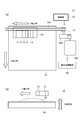
- FIG. 1 is a diagram illustrating an example of a printing apparatus 10 according to an embodiment of the present invention.
- FIG. 1A shows an example of the configuration of the main part of the printing apparatus 10.
- FIG. 1B shows a simplified operation for printing on the convex medium 50 to be printed.
- FIG. 3 is a diagram for explaining how ink droplets 302 ejected from nozzles 202 of the inkjet head 12 fly.
- FIG. 2A shows an example of how the ink droplets 302 fly.
- FIG. 2B is a diagram illustrating an example of an incident angle at the time of landing on the medium 50. It is a figure explaining the force which acts on the ink droplet 302 in the air. It is a figure explaining the operation
- FIG. 5A is a graph showing an example of setting of the moving speed Vy.
- FIG. 5B is a diagram for explaining the flying direction of the ink droplets. It is a graph explaining the practical limit of gap distance.
- the result of an experiment in which printing is performed with the inkjet head 12 stationary is shown.
- 6 is a diagram illustrating an example of a printing operation performed on the three-dimensional medium 50.
- FIG. 10A shows a first problem that occurs in the three-dimensional object forming apparatus.
- FIGS. 10B and 10C show a second problem that occurs in the three-dimensional object forming apparatus.
- FIG. 1 shows an example of a printing apparatus 10 according to an embodiment of the present invention.
- FIG. 1A shows an example of the configuration of the main part of the printing apparatus 10.
- FIG. 1B shows a simplified operation for printing on the convex medium 50 to be printed. Except for the points described below, the printing apparatus 10 may have the same or similar configuration as a known inkjet printer.
- the printing apparatus 10 is an ink jet printer that performs printing on the medium 50 by an ink jet method.
- the printing apparatus 10 is an inkjet printer that performs printing in a serial manner, for example, by causing an inkjet head to perform a main scanning operation, and includes a plurality of inkjet heads 12, a main scanning drive unit 14, an ultraviolet light source 16, and a table. 18, a sub-scanning drive unit 20, and a control unit 22.
- the plurality of inkjet heads 12 are print heads having nozzles that eject ink droplets onto the medium 50, and eject ink droplets to each position on the medium 50 by performing a main scanning operation in accordance with an instruction from the control unit 22. .
- the main scanning operation is an operation of ejecting ink droplets onto the medium 50 while moving in a preset main scanning direction (Y-axis direction in the drawing).
- the plurality of inkjet heads 12 eject ink droplets of ultraviolet curable ink.
- Each of the plurality of inkjet heads 12 ejects ink droplets of different colors. More specifically, each of the plurality of inkjet heads 12 ejects ink droplets of each color of CMYK ink.
- the printing apparatus 10 may further include inkjet heads 12 other than CMYK colors.
- the printing apparatus 10 may further include an inkjet head 12 for white or clear color.
- the plurality of inkjet heads 12 are arranged in the main scanning direction with their positions in the sub-scanning direction aligned.
- the sub-scanning direction is a direction (X-axis direction in the drawing) orthogonal to the main scanning direction.
- each inkjet head 12 has a nozzle row in which a plurality of nozzles are arranged in the sub-scanning direction.
- the main scanning driving unit 14 is a driving unit that causes the plurality of inkjet heads 12 to perform a main scanning operation.
- the main scanning drive unit 14 includes a carriage 102, a stepping motor 106, a gear 108, and a conveyance belt 104.
- the carriage 102 holds the plurality of inkjet heads 12 in a state where the nozzle surface of each inkjet head 12 and the medium 50 are opposed to each other.
- the nozzle surface of the inkjet head 12 is a surface where the nozzles are formed in the inkjet head 12.
- the stepping motor 106 is a motor serving as a power source for moving the plurality of inkjet heads 12 during the main scanning operation.
- the stepping motor 106 rotates at a speed according to an instruction from the control unit 22 to move the plurality of inkjet heads 12 at a preset speed during the main scanning operation.
- the gear 108 is a gear that transmits the power of the stepping motor 106 to the conveyance belt 104.
- the conveyance belt 104 is a belt member that moves the carriage 102 and is stretched so as to move the carriage 102 in the main scanning direction. Further, the conveyor belt 104 moves the carriage 102 by moving according to the power of the stepping motor 106 received via the gear 108. Accordingly, during the main scanning operation, the conveyance belt 104 moves the plurality of inkjet heads 12 in the main scanning direction.
- the main scanning drive unit 14 may further include, for example, a guide rail that guides the movement of the carriage 102.
- the ultraviolet light source 16 is an ultraviolet irradiation device, and cures the ultraviolet curable ink landed on the medium 50 by irradiating with ultraviolet rays.
- a UVLED can be preferably used as the ultraviolet light source 16.
- the printing apparatus 10 is a one-way print printer that performs only a main scanning operation in one direction.
- performing only the main scanning operation in one direction means that the direction of the main scanning operation of the inkjet head 12 is only one in the main scanning direction.
- the ultraviolet light source 16 is disposed only on one side in the main scanning direction with respect to the plurality of inkjet heads 12 as shown in FIG. This one side is the side that is behind the inkjet head 12 during the main scanning operation.
- the printing apparatus 10 may be configured for bidirectional printing that performs main scanning operation in both directions, for example.
- the table 18 is a table-like member on which the medium 50 is placed, and supports the medium 50 so as to face each nozzle surface of the plurality of inkjet heads 12. Further, the table 18 of this example has a function of moving the upper surface on which the medium 50 is placed in a predetermined vertical direction (Z-axis direction in the drawing). In this case, the vertical direction is a direction orthogonal to the main scanning direction and the sub-scanning direction.
- the table 18 of this example can adjust the distance between the nozzle surface of the inkjet head 12 and the table 18 by moving the upper surface in the vertical direction. Therefore, in this example, as shown in FIG. 1B, for example, printing can be performed even on a thick three-dimensional medium 50. The operation of printing on the three-dimensional medium 50 will be described in detail later.
- the sub-scanning drive unit 20 is a driving unit that causes the plurality of inkjet heads 12 to perform a sub-scanning operation.
- the sub-scanning operation is an operation that moves relative to the medium 50 in the sub-scanning direction.
- the sub-scan driving unit 20 is a driving unit that moves the main scanning driving unit 14 while holding a plurality of inkjet heads 12, and moves the main scanning driving unit 14 between main scanning operations. As a result, the plurality of inkjet heads 12 are caused to perform the sub-scanning operation.
- a configuration of the printing apparatus 10 for example, a configuration in which the position of the inkjet head 12 in the sub-scanning direction is fixed and the sub-scanning operation is performed by moving the medium 50 side may be used.
- the sub-scanning drive unit 20 for example, a drive unit that moves the table 18 can be used.
- the control unit 22 is, for example, a CPU of the printing apparatus 10 and controls the operation of each unit of the printing apparatus 10 according to an instruction from the host PC, for example. With the above configuration, the printing apparatus 10 performs printing on the medium 50. In this example, the control unit 22 controls the moving speed for moving the inkjet head 12 in the main scanning operation. The movement speed control will be described in more detail later.
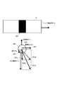
- FIG. 2 is a diagram for explaining how the ink droplets 302 ejected from the nozzles 202 of the inkjet head 12 fly.
- FIG. 2A is a diagram showing an example of how the ink droplets 302 fly, and shows a state observed from a position synchronized with the ink jet head.
- the velocity of the ink droplet 302 after ejection includes a component in the moving direction of the inkjet head 12 at the time of ejection according to the law of inertia. Become. Accordingly, the ejected ink droplet 302 moves toward the medium 50 while moving in the same direction as the inkjet head 12.
- the flying ink droplet 302 is affected by air resistance. As a result, the flying speed of the ink droplet 302 gradually changes after ejection. In addition, the influence of the air resistance received before the ink droplet 302 lands on the medium 50 increases as the gap distance increases. In this case, the gap distance is a distance between the nozzle surface of the inkjet head 12 and the medium 50.
- the left side with the symbol A indicates a case where the gap distance is large (wide gap) and the moving speed Vy of the inkjet head 12 during the main scanning operation is high.
- An example of the state of the ink droplet 302 flying is shown.
- the state of the ink droplet 302 flying in this figure is the state of the ink droplet 302 flying when the inkjet head 12 is viewed from the sub-scanning direction.
- the speed Vi in the ejection direction becomes slow, and the landing position is greatly affected by the moving speed Vy of the inkjet head 12. More specifically, for example, when the gap distance is large as shown in the drawing with the symbol A, the flight bend occurs, and the position where the ink dot 304 is formed by the landing of the ink droplet 302 is affected by the air resistance. Compared to the case without it, it will deviate greatly. Further, in this case, since the speed Vi in the ejection direction becomes slow, even if the landing timing is slightly shifted, the landing position shift becomes large. As a result, variations in landing positions also increase.
- the diagram on the right side with the symbol B shows an example of how the ink droplet 302 flies when the ink droplet 302 is ejected from the stopped inkjet head 12.
- the moving speed Vy of the ink jet head 12 is 0, even if the speed Vi of the ink droplet 302 in the ejection direction becomes slow due to the influence of air resistance, the ink droplet 302 lands on a position immediately below the nozzle 202. It will be. Therefore, in this case, even if the gap distance is increased, the landing position is not easily displaced.
- the speed Vi of the ink droplet 302 in the ejection direction is usually about 5 to 15 times the moving speed Vy of the inkjet head 12. For this reason, even if the inkjet head 12 is not completely stopped, for example, if the moving speed Vy is lowered, it becomes almost the same as the case where the reference symbol B is given, and it is considered that the landing position is not easily displaced.
- the appearance of the ejected ink droplet 302 varies depending on the moving speed Vy of the inkjet head 12. More specifically, for example, the greater the moving speed Vy of the inkjet head 12, the greater the magnitude of the flying bend that occurs before landing. As a result, as the moving speed Vy of the inkjet head 12 increases, the incident angle upon landing on the medium 50 increases.
- FIG. 2B is a diagram illustrating an example of an incident angle when landing on the medium 50.
- the ejected ink droplet 302 moves toward the medium 50 while moving in the same direction as the inkjet head 12.
- the flying direction of the ink droplet 302 gradually changes due to the flying bend caused by the air resistance.
- the ink droplets 302 land on the medium 50 at an incident angle ⁇ that changes according to the gap distance.
- the incident angle of the ink droplet 302 is an angle formed by the flying direction of the ink droplet 302 upon landing and the ejection direction in which the ink droplet 302 is ejected from the nozzle 202. More specifically, when the ink droplet 302 is ejected from the nozzle 202 downward in the vertical direction, the incident angle of the ink droplet 302 is the flight direction of the ink droplet 302 at the time of landing and the vertical downward direction. Is the angle formed by
- the incident angle ⁇ increases as the velocity Vi of the ink droplet 302 in the ejection direction decreases. Further, the deviation or variation in the landing position of the ink droplet 302 increases as the incident angle ⁇ increases.
- the moving speed Vy of the inkjet head 12 is constant, the incident angle ⁇ increases as the gap distance increases.
- the incident angle ⁇ increases as the moving speed Vy increases.
- the moving speed Vy of the ink jet head 12 may be changed in accordance with the gap distance in order to suppress the deviation or variation of the landing position. Therefore, this point will be described in more detail.
- FIG. 3 is a diagram illustrating the force acting on the ink droplet 302 in the air.
- the flying ink droplet 302 receives ejection inertia force Fi, lateral inertia force Fy, gravity Fg, and air resistance Fr.
- the lateral inertia force Fy is a force corresponding to the moving speed Vy of the inkjet head 12 at the time of ejection.
- the ink droplet 302 immediately after ejection flies at a speed indicated by an arrow 404 in the moving direction of the inkjet head 12 (hereinafter referred to as a lateral direction).
- the lateral inertia force Fy is a force that causes a shift or variation in the landing position.
- the gravity Fg is the gravity that the ink droplet 302 receives.
- the air resistance Fr is the air resistance received by the flying ink droplet 302.
- the ink droplet 302 receives an air resistance Fr in a direction opposite to the direction in which the nozzle 202 ejects the ink droplet 302, that is, in a direction opposite to gravity.
- the direction and speed of the flying speed of the ink droplet 302 are as indicated by an arrow 410a, for example.
- the air resistance Fr received by the flying ink droplet 302 in the ejection direction is usually larger than the gravity Fg.
- the speed of the ink droplet 302 in the ejection direction gradually decreases.
- This slow speed is, for example, a speed indicated by an arrow 402b that is shorter than the arrow 402a.
- the moving speed Vy of the inkjet head 12 is usually smaller than the ejection speed of the ink droplet 302. Therefore, in the lateral direction, the change in the velocity of the ink droplet 302 due to the air resistance can be almost ignored as compared with the change in the ejection direction. Therefore, the velocity component of the ink droplet 302 in the lateral direction can be regarded as substantially constant until it reaches the medium 50.
- the direction and speed of the flying speed of the ink droplet 302 are as indicated by the arrow 410b, for example.
- the ratio of the speed in the discharge direction to the speed in the horizontal direction changes, and the influence of the speed in the horizontal direction is greater than that immediately after discharge. It can be said that it is getting bigger.
- the lateral bending increases. As a result, it can be seen that the incident angle upon landing increases.
- FIG. 4 is a diagram for explaining the printing operation performed in this example, and shows an example of the operation and control when printing on the three-dimensional medium 50.
- the three-dimensional medium 50 is, for example, a medium 50 whose printing surface is not flat as shown in the figure. Further, the printing surface is, for example, a surface facing the ink jet head 12.
- FIG. 4 shows a simplified configuration of the printing apparatus 10 shown in FIG.
- the moving speed Vy of the inkjet head 12 during the main scanning operation is constant, if the gap distance changes, the flying direction of the ink droplet 302 at the time of landing changes. As a result, when the gap distance is increased, the incident angle of the ink droplet 302 at the time of landing is increased, and the deviation or variation of the landing position is likely to increase.
- the control unit 22 sets the moving speed Vy of the inkjet head 12 during the main scanning operation according to the gap distance. More specifically, for example, with respect to the moving speed Vy of the inkjet head 12 in the main scanning operation, the medium is at least at the position where the gap distance is the largest in the region of the medium 50 that is the target of each main scanning operation.
- the incident angle at the time of landing of the ink droplet on 50 is set to be 45 degrees or less.
- the moving speed of the inkjet head 12 during the main scanning operation can be changed along the substantially dome shape.
- the position where the gap distance becomes the largest may be, for example, the position where the gap distance becomes the largest among the landing positions determined according to the printing resolution.
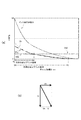
- FIG. 5 is a diagram illustrating an example of control of the moving speed Vy of the inkjet head 12.
- FIG. 5A is a graph showing an example of setting of the moving speed Vy.
- FIG. 5B is a diagram for explaining the flying direction of the ink droplets.
- the ink drop initial velocity V0 is a discharge speed at which the inkjet head 12 discharges ink drops from the nozzles.
- the velocity V0 may be a velocity in the ejection direction of the ink droplet immediately after being ejected from the nozzle.
- ⁇ is a speed decay time constant determined according to the ink droplet volume and the like.
- the speed at which the ink droplets fly has a component in the lateral direction orthogonal to the ejection direction.
- the speed of the ink droplet in the lateral direction is the same as the moving speed of the inkjet head 12.
- the velocity of the ink droplets in the lateral direction is considered to be almost constant. Can do.
- the control unit 22 sets at least the moving speed Vh of the inkjet head 12 at each timing of ejecting ink droplets to each position in the region of the medium 50 that is the target of the main scanning operation. Until the ink droplets land on the medium 50, Vh ⁇ Vi is set. If comprised in this way, the moving speed Vh of the inkjet head 12 can be set appropriately according to the gap distance.
- a dotted line indicated as Vh0 is a reference line indicating a case where the moving speed of the inkjet head 12 is set to a predetermined constant value Vh0.
- Vi ⁇ Vh0, and the incident angle upon landing can be 45 degrees or more.
- Vi ⁇ Vh0, and the incident angle at the time of landing is large. As a result, a landing position shift or the like is likely to occur.
- setting Vh so that Vi ⁇ Vh corresponds to setting Vh so that it is always below the curve of Vi.
- the incident angle of the ink droplet at the landing is 45 degrees or less.
- the ink droplet ejection speed is usually about 5 to 15 times the moving speed of the inkjet head. Therefore, when the gap distance is small, the incident angle of the ink droplet is usually smaller than 45 degrees, for example, about 20 degrees or less. In consideration of this point, even when the gap distance becomes large, for example, without changing the direction of the combined vector shown in FIG. 5B, the incident angle is similar to that when the gap distance is small. It is more preferable to land the ink droplets.
- N is a constant of about 1 to 15, and the controller 22 causes the controller 22 to move the moving speed Vh so that Vi / Vh ⁇ N for each position in the area of the medium 50 to be subjected to the main scanning operation. Can be set.
- the speed Vi may be a speed at the timing of landing, for example.
- the range where Vi / Vh ⁇ N with respect to the moving speed Vh of the inkjet head 12 is a region (stable print region) where printing can be performed more stably.
- the moving speed of the inkjet head 12 is constant (Vh0) as in the conventional configuration, for example, the curve Vh and the dotted line Vh0 are short as shown in the graph as the conventional stable print region. Printing can be performed stably only within the range.
- the moving speed of the inkjet head 12 can be appropriately set within a range not exceeding the curve Vh in the graph. For example, as indicated by the curve Vha in the graph, a slower speed than that indicated by the curve Vh may be set. By setting in this way, the speed according to the gap distance can be appropriately set for the moving speed of the inkjet head 12.
- a certain upper limit value may be provided for the moving speed, and the moving speed when the gap distance is small may be limited. More specifically, in this case, while the inkjet head 12 performs one main scanning operation, the control unit 22 moves the moving speed with respect to a position where the gap distance is equal to or smaller than a preset gap that is a preset distance. Is set to a preset maximum speed Vh max , and the moving speed is set to a speed lower than the maximum speed Vh max with respect to a position where the gap distance is larger than the set gap. If comprised in this way, it can prevent appropriately that the moving speed of the inkjet head 12 becomes high speed too much. In addition, this makes it possible to appropriately prevent, for example, difficulty in control and a significant increase in the cost of the device.
- the moving speed of the inkjet head 12 is changed according to the gap distance at each position so as to gradually decrease from the constant speed according to the gap distance, for example, in each main scanning operation.
- the control unit 22 performs ink in each position according to the gap distance at each position in the region of the medium 50 that is the target of the main scanning operation.
- the moving speed of the inkjet head 12 at the timing of ejecting droplets is changed. If comprised in this way, the moving speed of the inkjet head 12 can be set appropriately according to the gap distance in each position. In addition, this makes it possible to appropriately perform printing with high accuracy even when the gap distance is large at any position.
- the moving speed of the inkjet head 12 may be changeable in a plurality of preset stages (eg, about 3 to 5 stages), for example.
- the control unit 22 changes the moving speed of the inkjet head 12 by selecting from a plurality of stages.
- the moving speed of the inkjet head 12 may be set for each main scanning operation without being changed in one main scanning operation, for example.
- the control unit 22 sets the moving speed of the inkjet head 12 for each main scanning operation.
- the control part 22 may set the moving speed of the inkjet head 12 for every preset multiple main scanning operation
- the control unit 22 may set the moving speed of the inkjet head 12 to a preset maximum speed. More specifically, when the maximum value of the gap distance in the area of the medium 50 that is the target of the main scanning operation is equal to or less than a set gap that is a preset distance, the control unit 22 performs the main scanning operation. The moving speed of the inkjet head 12 is set to a preset maximum speed. When the gap distance is larger than the set gap at any position in the area of the medium 50 that is the target of the main scanning operation, the control unit 22 determines the moving speed in the main scanning operation as the gap in the area. Set according to the maximum distance. In such a configuration, the lowest moving speed corresponding to the maximum value of the gap distance is used for all the gap distances. If comprised in this way, about the moving speed of the inkjet head 12, the speed according to gap distance can be set more simply and appropriately.
- the printing operation performed using the printing apparatus 10 of this example will be described more specifically.
- the state when the ink droplets land differs depending on the gap distance. For example, when the gap distance is small, the drop in the speed of ink droplets until landing is small, and the landing position is accurate.
- printing is performed at high speed, for example, by setting the moving speed of the inkjet head 12 to the maximum speed.
- the moving speed of the inkjet head 12 is fast, the landing position of the ink droplet becomes slightly inaccurate.
- the moving speed of the inkjet head 12 is made slower than the maximum speed, and printing is performed at a medium speed.
- the speed of the inkjet head 12 is greatly reduced by the time of landing. Therefore, in this case, if the moving speed of the inkjet head 12 is fast, the landing positions of the ink droplets are greatly shifted.
- printing is performed with the moving speed of the inkjet head 12 as slow as possible.
- the stepping motor 106 is used as the power source of the main scanning drive unit 14. In this case, the ink-jet head 12 can be temporarily stopped when ink droplets are ejected. Therefore, when the gap distance is large, the speed of the inkjet head 12 may be set to 0 when ejecting ink droplets.
- the control unit 22 when the gap distance is larger than a preset upper limit distance at any position on the medium 50, the control unit 22 at least drops the ink droplet to a position where the gap distance is larger than the upper limit distance.
- the inkjet head 12 may be stationary at the timing of discharging the ink.
- the upper limit distance may be a distance of about 10 mm, for example.
- the moving speed of the inkjet head 12 is automatically controlled as follows according to the gap distance. For example, for each medium 50 to be printed, it is conceivable to determine the moving speed of the inkjet head 12 according to the maximum gap distance in the medium 50. In this case, the same moving speed is used for the entire medium 50. For example, when the gap distance at any position is large, the entire medium 50 is printed at a low speed.
- the moving speed of the inkjet head 12 corresponding to the gap distance may be changed manually by a user operation or may be set automatically.
- the ink droplets are ejected by stopping the stepping motor 106 that is a driving source for moving the inkjet head 12. Also good. If printing is performed as described above, printing can be appropriately performed on the medium 50 having various gap distances.
- a decrease in the printing speed may be a problem.
- increasing the number of inkjet heads 12 for each color may reduce the influence of a decrease in moving speed of the inkjet head 12.
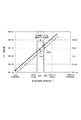
- FIG. 6 is a graph for explaining the practical limit of the gap distance, and shows an example of the relationship between the time constant related to the velocity attenuation of the ink droplet in air, the size of the ink droplet, and the critical gap.
- the time constant relating to the velocity attenuation of the ink droplet in the air is, for example, the time constant ⁇ described in relation to FIG.
- the ink droplet size refers to the droplet diameter and droplet volume shown in the graph of FIG. In this case, the droplet is an ink droplet.
- the limit gap is the maximum gap distance that can be printed when the surroundings are in a windless state.
- the solid line represents the maximum reach distance when ink droplets are ejected with the inkjet head 12 stationary (during stationary printing).
- the limit gap becomes equal to the maximum reach distance Lmax of the ink droplet.
- the maximum reach distance Lmax of the ink droplet is, for example, a distance at which the speed of the ink droplet in the ejection direction becomes zero.
- a broken straight line indicates a limit gap when the inkjet head 12 is moved at a speed of 1 m / sec.
- the limit gap is smaller than the maximum reach distance Lmax.
- the limit gap approaches the maximum reach distance Lmax. Therefore, when the moving speed of the inkjet head 12 is changed according to the gap distance as in this example, it can be said that the limit gap is theoretically a value close to the maximum reach distance Lmax.
- ink droplets having the size shown in the graph are used as the droplet size range of the high-definition head.
- the gap distance is about 10 mm or less, high-definition printing can be appropriately performed when the ink droplet capacity is larger than about 6 pl. It can be said.
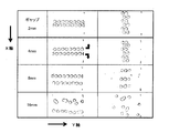
- FIG. 7 shows the results of an experiment in which printing was performed with the inkjet head 12 stationary.
- the inkjet head 12 is moved by the power of the stepping motor 106.
- the inkjet head 12 was stopped at the timing when the inkjet head 12 reached each position where ink droplets were ejected. Then, ink droplets were ejected from the stationary inkjet head 12.
- the Y direction shown in the figure is the head moving direction.
- the limit gap is appropriately set by, for example, reducing the moving speed of the ink jet head 12 according to the gap distance, compared with the conventional configuration, for example. Can be bigger. Therefore, also from this experiment, it can be seen that the configuration of this example can appropriately perform printing with high accuracy even when the gap distance is large.
- FIG. 8 shows an example of a printing operation performed on the three-dimensional medium 50.
- the printing apparatus 10 changes the moving speed of the inkjet head 12 according to the gap distance in each position. More specifically, for example, in the case shown in FIG. 8, the moving speed of the inkjet head 12 is set to the maximum speed Vh_max for a position where the gap distance is small. For the position where the gap distance is medium, the moving speed of the inkjet head 12 is set to the medium speed Vh_mid. For the position where the gap distance is large, the moving speed of the inkjet head 12 is set to the lowest speed Vh_min. If comprised in this way, the moving speed of the inkjet head 12 can be set appropriately according to gap distance.
- the moving speed of the inkjet head 12 is gradually or stepwise reduced not only at a position where the gap distance is large, but also at a position where the landing position is likely to be disturbed, such as a position at the end of a figure. May be.
- the position that becomes the end of the figure is, for example, a position surrounded by a broken line in FIG. If comprised in this way, it can print more appropriately with respect to the three-dimensional medium 50, for example.
- the configuration in which the moving speed of the inkjet head 12 is variable can be suitably used at times other than when printing on the three-dimensional medium 50. More specifically, for example, as described below, when printing a thin straight line extending in the X-axis direction, the moving speed of the inkjet head 12 may be reduced.
- FIG. 9 shows the results of an experiment regarding the relationship between the direction of the straight line to be drawn and how the landing position is shifted.
- thin lines in the X-axis direction and the Y-axis direction were printed with the moving speed of the inkjet head 12 kept constant. Further, the gap distance was varied in the range of 2 to 16 mm.
- the speed of the ink droplets may be reduced near the end of the ink jet head 12 due to the influence of the self-stream generated along with the movement of the ink jet head 12.
- the positions of the fine lines extending in the Y-axis direction and the ink dots formed by the nozzles at the end of the inkjet head 12 may shift outward as indicated by the arrows in the figure.
- the influence of the disturbance of the landing position becomes large.
- FIG. 10 is a diagram for explaining the operation when the printing apparatus 10 is used as a three-dimensional object shaping apparatus, and shows an example of a problem that may occur when the moving speed of the inkjet head 12 is made constant.
- FIG. 10A shows a first problem that occurs in the three-dimensional object forming apparatus.
- the printing apparatus 10 is used as a three-dimensional object forming apparatus (such as a 3D printer)
- a three-dimensional object is formed by stacking a plurality of ink layers on the table 18.
- the speed of the ink droplets at the head portion is usually slightly reduced due to the influence of the surrounding atmosphere.
- the interval between the ink dots 304 is slightly clogged in the head portion, and the position of the upper surface of the ink layer is slightly higher than the other portions. Such a change is inconspicuous when performing normal printing (2D printing).
- the moving speed of the inkjet head 12 can be slowed to reduce the error. Moreover, this can prevent appropriately the difference in height caused by an error in the three-dimensional object to be modeled.
- FIGS. 10B and 10C show the second problem that occurs in the three-dimensional object forming apparatus.
- FIG. 10B shows an example of the first ink layer formed on the table 18.
- FIG. 10C shows an example of a state in which a plurality of ink layers are stacked.
- a three-dimensional object is modeled by overlapping and forming a plurality of ink layers.
- Each ink layer is formed by causing the inkjet head 12 to perform a main scanning operation.
- the ink droplets are incident from an oblique direction.
- the incident angle is determined according to the ejection speed of ink droplets from the nozzles of the inkjet head 12, the moving speed of the inkjet head 12 during ejection, and the like.
- the incident in the oblique direction exerts a force in a direction that causes the dots 304 to protrude outward from the layer. Therefore, the upper layer dots 304 are likely to drop off in the vicinity of this end. As a result, the surface of the three-dimensional object to be modeled may become rough.
- the moving speed of the inkjet head 12 can be slowed in the vicinity of the end where the dots 304 are likely to drop off. Thereby, it can prevent that the surface of the solid object to be modeled becomes rough. Therefore, when the configuration of the printing apparatus 10 of the present example is used, the modeling of the three-dimensional object can be performed more appropriately.
- the present invention can be suitably used for a printing apparatus, for example.
Landscapes
- Engineering & Computer Science (AREA)
- Quality & Reliability (AREA)
- Ink Jet (AREA)
- Particle Formation And Scattering Control In Inkjet Printers (AREA)
- Application Of Or Painting With Fluid Materials (AREA)
- Coating Apparatus (AREA)
Abstract
ギャップ距離が大きい場合にも、高い精度でより適切に印刷を行う。 インクジェットヘッド12と、主走査駆動部14と、制御部22とを備え、制御部22は、ギャップ距離に応じて、インクジェットヘッド12の移動速度を設定し、かつ、主走査動作における移動速度について、少なくとも、当該主走査動作の対象となる媒体の領域のうち、ギャップ距離が最も大きくなる位置に対し、媒体50へのインク滴の着弾時における入射角度が45度以下になるように設定する。
Description
本発明は、印刷装置及び印刷方法に関する。
近年、立体物等の様々な形状の物体に対しての印刷が可能なインクジェットプリンタが開発されている(例えば、特許文献1参照。)。また、このようなインクジェットプリンタとして、インクジェットヘッドに主走査動作(スキャン動作)を行わせるシリアル型のインクジェットプリンタが広く用いられている。
立体物等の様々な形状の物体を印刷の対象物(プリント物)である媒体として用いる場合、媒体とインクジェットヘッドとの間の距離であるギャップ距離(ギャップ長)が大きくなる場合がある。しかし、インクジェット方式で印刷を行う場合、ギャップ距離が大きくなると、インク滴の着弾位置のずれやバラツキが大きくなりやすい。また、その結果、高い精度で印刷を行うことが難しくなる場合がある。そのため、従来、ギャップ距離が大きい場合にも高い精度でより適切に印刷を行える構成が望まれていた。そこで、本発明は、上記の課題を解決できる印刷装置及び印刷方法を提供することを目的とする。
本願の発明者は、インクジェット方式で印刷を行う場合の、ギャップ距離と着弾位置のずれ等との関係等について、鋭意研究を行った。そして、先ず、ギャップ距離がある程度の距離よりも大きくなると、着弾位置のずれやバラツキが顕著になることに着目した。また、更なる鋭意研究により、着弾位置のずれ等の大きさについて、インクジェットヘッドのノズルから吐出されたインク滴が媒体に着弾する着弾時の入射角度との関係が大きいことを見出した。
より具体的には、従来の構成によりインクジェット方式で印刷を行う場合について、ギャップ距離が大きくなると、着弾時のインク滴の入射角度も大きくなることに着目した。この場合、インク滴の入射角度とは、着弾時のインク滴の飛翔方向と、ノズルからインク滴を吐出する吐出方向とがなす角度のことである。より具体的には、例えば、鉛直方向の下側へ向けてノズルからインク滴を吐出する場合、インク滴の入射角度とは、着弾時のインク滴の飛翔方向と、鉛直下向きの方向とがなす角度である。そして、本願の発明者は、更に、ギャップ距離が大きい場合について、着弾時の入射角度が大きくなることで、着弾位置のずれ等が大きくなっていることを見出した。
ここで、インクジェットヘッドに主走査動作を行わせることで印刷を行う場合、主走査動作時に、インクジェットヘッドは、予め設定された主走査方向へ移動しつつ、インク滴を吐出する。そのため、ノズルから吐出されたインク滴の飛翔方向は、慣性の法則により、吐出時のインクジェットヘッドの移動方向の成分を有することになる。
しかし、インクジェットヘッドにおいて、ノズルからインク滴を吐出する吐出速度(初速)は、通常、インクジェットヘッドの移動速度と比べて十分に大きい。より具体的には、インク滴の吐出速度は、通常、インクジェットヘッドの移動速度の5~15倍程度である。そのため、インク滴の吐出直後において、インク滴の飛翔方向は、吐出方向に近い方向になる。
また、ギャップ距離が小さい場合(例えば、2mm以下程度の場合)、インク滴の飛翔方向は、吐出直後からの変化は小さいと考えられる。そのため、この場合、着弾時のインク滴の入射角度は、吐出直後と同程度の小さい角度になると考えられる。この場合、吐出直後のインク滴の飛翔方向とは、インク滴の吐出速度と、インクジェットヘッドの移動速度との合成により決まる方向である。そして、この場合、インク滴の入射角度が小さくなるため、着弾位置のずれ等は生じにくい。
一方、ギャップ距離が大きい場合、空気抵抗によるインク滴の飛翔速度の変化が大きくなるため、インク滴の入射角度について、吐出直後と同程度とは言えなくなる。より具体的には、空気抵抗の影響は、通常、速度が速いほど大きくなる。そのため、ノズルからの吐出後において、より高速である吐出方向の速度成分は、空気抵抗の影響を大きく受けることになる。また、その結果、ギャップ距離が大きくなると、着弾時におけるインク滴の入射角度は、徐々に大きくなる。そして、入射角度が大きくなることにより、着弾位置のずれ等が生じやすくなる。また、ギャップ距離が大きい場合において、吐出方向の速度が小さくなり過ぎると、インク滴のミスト化等が生じる場合もある。
ここで、上記においても説明をしたように、インク滴の飛翔方向は、吐出時におけるインクジェットヘッドの移動速度の影響も受ける。そして、上記の説明等から明らかなように、着弾時の入射角度は、インクジェットヘッドの移動速度が遅い程、小さくなる。
そこで、本願の発明者は、主走査動作時のインクジェットヘッドの移動速度をギャップ距離に応じて変化させ、ギャップ距離が大きい場合に移動速度を遅くすることを考えた。また、より具体的には、例えば、着弾時の入射角度が45度以下になるようにインクジェットヘッドの移動速度を調整することを考えた。このように構成すれば、着弾直前におけるインク滴の飛翔方向について、インクジェットヘッドの移動方向の成分よりも、媒体へ向かう成分を大きくできる。また、これにより、着弾位置のずれ等が大きくなることを適切に防ぐことができると考えられる。また、媒体へ向かう成分をある程度保ったまま着弾することになるため、インク滴のミスト化等も適切に防ぐことができると考えられる。すなわち、上記の課題を解決するために、本発明は、以下の構成を有する。
(構成1)媒体に対してインクジェット方式で印刷を行う印刷装置であって、媒体へインク滴を吐出するノズルを有するインクジェットヘッドと、予め設定された主走査方向へ移動しつつインク滴を吐出する主走査動作をインクジェットヘッドに行わせる主走査駆動部と、主走査動作においてインクジェットヘッドを移動させる移動速度を制御する制御部とを備え、制御部は、インクジェットヘッドにおいてノズルが形成されている面であるノズル面と、媒体と、の間の距離であるギャップ距離に応じて、移動速度を設定し、かつ、主走査動作における移動速度について、少なくとも、当該主走査動作の対象となる媒体の領域のうち、ギャップ距離が最も大きくなる位置に対し、媒体へのインク滴の着弾時における入射角度が45度以下になるように設定する。
この構成において、媒体とは、例えば、印刷の対象物のことである。この媒体は、例えば立体物等であってよい。また、ギャップ距離が最も大きくなる位置とは、例えば、印刷の解像度に応じて決まる着弾位置のうち、ギャップ距離が最も大きくなる位置であってよい。
このように構成すれば、ギャップ距離が大きくなる着弾位置においても、インク滴の入射角度が大きくなり過ぎることを適切に防ぐことができる。また、これにより、着弾位置のずれ等を適切に抑えることができる。また、この場合、媒体へ向かう成分をある程度保ったままインク滴が着弾することになるため、インク滴のミスト化等も適切に防ぐことができる。そのため、このように構成すれば、ギャップ距離が大きい場合にも、高い精度でより適切に印刷を行うことができる。
(構成2)制御部は、インクジェットヘッドが1回の主走査動作を行う間に、当該主走査動作の対象となる媒体の領域内の各位置におけるギャップ距離に応じて、各位置へインク滴を吐出するタイミングにおける移動速度を変更する。
このように構成すれば、各位置におけるギャップ距離に合わせて、インクジェットヘッドの移動速度を適切に設定できる。また、これにより、いずれかの位置においてギャップ距離が大きい場合にも、高い精度で適切に印刷を行うことができる。
(構成3)制御部は、ギャップ距離が予め設定された距離である設定ギャップ以下である位置に対し、移動速度を予め設定された最大の速度に設定し、ギャップ距離が設定ギャップよりも大きくなる位置に対し、移動速度を最大の速度よりも低い速度に設定する。
ギャップ距離が小さい場合には、インクジェットヘッドの移動速度を極めて高速にしても、着弾位置のずれ等は生じにくいと考えられる。しかし、インクジェットヘッドの移動速度を高速にし過ぎると、制御が難しくなるおそれもある。また、装置への要求性能が高まるため、装置のコストが大幅に増大するおそれもある。
これに対し、このように構成した場合、インクジェットヘッドの移動速度について、所定の最大の速度を設定することで、これらの問題が生じることを適切に防ぐことができる。また、ギャップ距離が大きい場合には、インクジェットヘッドの移動速度を遅くすることにより、着弾位置のずれ等を適切に抑えることができる。そのため、このように構成すれば、ギャップ距離が大きい場合にも、高い精度でより適切に印刷を行うことができる。
(構成4)インクジェットヘッドがノズルからインク滴を吐出する吐出速度をV0とし、ノズルからインク滴が吐出された後に経過した時間をtとして、インク滴の飛翔速度のうち、インク滴の吐出方向の成分であるViについて、時定数τを用いて、Vi=V0×exp(-t/τ)と近似した場合、制御部は、主走査動作の対象となる媒体の領域内の各位置へインク滴を吐出するタイミングにおけるインクジェットヘッドの移動速度Vhを、少なくとも、各位置へ吐出された各インク滴が媒体へ着弾するまでの間、Vh≦Viとなるように設定する。このように構成すれば、例えば、インクジェットヘッドの移動速度について、ギャップ距離に応じた速度を適切に設定できる。
(構成5)移動速度について予め設定された最大の速度をVhmaxとし、インクジェットヘッドがノズルからインク滴を吐出する吐出速度をV0とし、N=V0/Vhmaxとした場合、制御部は、主走査動作の対象となる媒体の領域内の各位置について、インクジェットヘッドの移動速度Vhと、着弾位置でのインク滴の飛翔速度のうち、インク滴の吐出方向の成分であるViとの関係について、Vi/Vh≧Nとなるように、移動速度Vhを設定する。この場合、速度Viは、例えば、着弾のタイミングにおける速度であってよい。このように構成すれば、例えば、インクジェットヘッドの移動速度について、ギャップ距離に応じた速度を適切に設定できる。
(構成6)制御部は、インクジェットヘッドの移動速度を主走査動作毎に設定し、主走査動作の対象となる媒体の領域内でのギャップ距離の最大値が予め設定された距離である設定ギャップ以下である場合、制御部は、当該主走査動作における移動速度を、予め設定された最大の速度に設定し、主走査動作の対象となる媒体の領域内のいずれかの位置において、ギャップ距離が設定ギャップより大きくなる場合、制御部は、当該主走査動作における移動速度を、当該領域内でのギャップ距離の最大値に応じて設定する。各回の主走査動作において、制御部は、インクジェットヘッドを、例えば、一定の移動速度で移動させる。
このように構成した場合、例えば、ギャップ距離が最大になる位置に合わせてインクジェットヘッドの移動速度を設定することにより、ギャップ距離が大きい場合にも、インク滴の着弾位置のずれ等を適切に抑えることができる。また、例えば、インクジェットヘッドの速度について、最大の速度を設定することや、各回の主走査動作中における移動速度を一定にすることにより、制御が複雑になること等を適切に防ぐことができる。そのため、このように構成すれば、インクジェットヘッドの移動速度について、ギャップ距離に応じた速度をより簡易かつ適切に設定できる。
尚、制御部は、インクジェットヘッドの移動速度を、例えば、1回の主走査動作毎に設定する。また、制御部は、予め設定された複数回の主走査動作毎に、インクジェットヘッドの移動速度を設定してもよい。
(構成7)媒体におけるいずれかの位置においてギャップ距離が予め設定された上限距離よりも大きい場合、制御部は、少なくとも、ギャップ距離が上限距離よりも大きくなる位置へインク滴を吐出するタイミングにおいて、インクジェットヘッドを静止させる。この上限距離は、例えば、10mm程度の距離であってよい。
このように構成すれば、ギャップ距離が特に大きい場合にも、着弾位置のずれ等を適切に抑えることができる。また、これにより、高い精度での印刷をより適切に行うことができる。
尚、この構成において、主走査駆動部は、例えば、インクジェットヘッドの移動の動力源として、ステッピングモータを有することが好ましい。この場合、ステッピングモータを適宜停止させることにより、インクジェットヘッドを適切に静止させることができる。
(構成8)媒体に対してインクジェット方式で印刷を行う印刷方法であって、媒体へインク滴を吐出するノズルを有するインクジェットヘッドに、予め設定された主走査方向へ移動しつつインク滴を吐出する主走査動作を行わせ、かつ、主走査動作においてインクジェットヘッドを移動させる移動速度を制御し、移動速度の制御において、インクジェットヘッドにおいてノズルが形成されている面であるノズル面と、媒体と、の間の距離であるギャップ距離に応じて、移動速度を設定し、かつ、主走査動作における移動速度について、少なくとも、当該主走査動作の対象となる媒体の領域のうち、ギャップ距離が最も大きくなる位置に対し、媒体へのインク滴の着弾時における入射角度が45度以下になるように設定する。このように構成すれば、例えば、構成1と同様の効果を得ることができる。
本発明によれば、例えば、ギャップ距離が大きい場合にも、高い精度でより適切に印刷を行うことができる。
以下、本発明に係る実施形態を、図面を参照しながら説明する。図1は、本発明の一実施形態に係る印刷装置10の一例を示す。図1(a)は、印刷装置10の要部の構成の一例を示す。図1(b)は、印刷対象である凸状の媒体50への印刷を行う動作を簡略化して示す。尚、以下に説明をする点以外について、印刷装置10は、公知のインクジェットプリンタと同一又は同様の構成を有してよい。
印刷装置10は、媒体50に対してインクジェット方式で印刷を行うインクジェットプリンタである。また、本例において、印刷装置10は、例えばインクジェットヘッドに主走査動作を行わせ、シリアル方式で印刷を行うインクジェットプリンタであり、複数のインクジェットヘッド12、主走査駆動部14、紫外線光源16、テーブル18、副走査駆動部20、及び制御部22を備える。
複数のインクジェットヘッド12は、媒体50へインク滴を吐出するノズルを有する印刷ヘッドであり、制御部22の指示に応じて主走査動作を行うことにより、媒体50の各位置へインク滴を吐出する。この場合、主走査動作とは、予め設定された主走査方向(図中のY軸方向)へ移動しつつ媒体50へインク滴を吐出する動作である。また、本例において、複数のインクジェットヘッド12は、紫外線硬化型インクのインク滴を吐出する。また、複数のインクジェットヘッド12のそれぞれは、それぞれ異なる色のインクのインク滴を吐出する。より具体的には、複数のインクジェットヘッド12のそれぞれは、CMYKインクのそれぞれの色のインク滴を吐出する。
尚、印刷装置10は、CMYKの各色以外のインクジェットヘッド12を更に備えてもよい。例えば、印刷装置10は、白色やクリア色用のインクジェットヘッド12を更に備えてもよい。また、本例において、複数のインクジェットヘッド12は、副走査方向における位置を揃えて、主走査方向へ並べて配設されている。この場合、副走査方向とは、主走査方向と直交する方向(図中のX軸方向)である。また、図示は省略したが、本例において、それぞれのインクジェットヘッド12は、複数のノズルが副走査方向へ並ぶノズル列を有する。
主走査駆動部14は、複数のインクジェットヘッド12に主走査動作を行わせる駆動部である。本例において、主走査駆動部14は、キャリッジ102、ステッピングモータ106、ギア108、及び搬送ベルト104を有する。キャリッジ102は、それぞれのインクジェットヘッド12におけるノズル面と媒体50と対向させた状態で、複数のインクジェットヘッド12を保持する。この場合、インクジェットヘッド12のノズル面とは、インクジェットヘッド12においてノズルが形成されている面のことである。
ステッピングモータ106は、主走査動作時に複数のインクジェットヘッド12を移動させる動力源となるモータである。本例において、ステッピングモータ106は、制御部22の指示に応じた速度で回転することにより、主走査動作時において、予め設定された速度で複数のインクジェットヘッド12を移動させる。ギア108は、ステッピングモータ106の動力を搬送ベルト104へ伝えるギアである。
搬送ベルト104は、キャリッジ102を移動させるベルト部材であり、キャリッジ102を主走査方向へ移動させるように張り渡されている。また、搬送ベルト104は、ギア108を介して受け取るステッピングモータ106の動力に応じて移動することにより、キャリッジ102を移動させる。また、これにより、主走査動作時において、搬送ベルト104は、複数のインクジェットヘッド12を、主走査方向へ移動させる。尚、主走査駆動部14は、例えば、キャリッジ102の移動をガイドするガイドレール等を更に有してよい。
紫外線光源16は、紫外線照射装置であり、媒体50へ着弾した紫外線硬化型インクを、紫外線を照射することにより硬化させる。紫外線光源16としては、例えばUVLED等を好適に用いることができる。
ここで、図1(a)に図示した場合において、印刷装置10は、片方向への主走査動作のみを行う片方向プリントプリンタである。この場合、片方向への主走査動作のみを行うとは、インクジェットヘッド12の主走査動作の方向を、主走査方向における一方のみにすることである。また、この場合、紫外線光源16は、図1(a)に示すように、複数のインクジェットヘッド12に対し、主走査方向における一方側にのみ配設される。この一方側は、主走査動作時にインクジェットヘッド12の後方になる側である。
また、印刷装置10は、例えば、両方向への主走査動作を行う双方向プリント用の構成にしてもよい。この場合、例えば、インクジェットヘッド12に対し、主走査方向の両側に紫外線光源16を配設することが好ましい。また、例えば片方向への主走査動作のみを行う場合においても、インクジェットヘッド12に対し、主走査方向の両側に紫外線光源16を配設してもよい。
テーブル18は、媒体50を載置する台状部材であり、複数のインクジェットヘッド12のそれぞれのノズル面と対向させて媒体50を支持する。また、本例のテーブル18は、媒体50を載置する上面を、所定の上下方向(図中のZ軸方向)へ移動させる機能を有する。この場合、上下方向とは、主走査方向及び副走査方向と直交する方向である。
ここで、上面を上下方向へ移動させることにより、本例のテーブル18は、インクジェットヘッド12のノズル面と、テーブル18との間の距離を適宜調整できる。そのため、本例においては、例えば図1(b)に示すように、厚みのある立体的な媒体50に対しても、印刷を行うことができる。立体的な媒体50に対して印刷を行う動作については、後に詳しく説明をする。
副走査駆動部20は、複数のインクジェットヘッド12に副走査動作を行わせる駆動部である。この場合、副走査動作とは、副走査方向へ媒体50に対して相対的に移動する動作のことである。また、本例において、副走査駆動部20は、複数のインクジェットヘッド12を保持した状態で主走査駆動部14を移動させる駆動部であり、主走査動作の合間に主走査駆動部14を移動させることにより、複数のインクジェットヘッド12に副走査動作を行わせる。
尚、印刷装置10の構成としては、例えば、副走査方向におけるインクジェットヘッド12の位置を固定して、媒体50の側を移動させることで副走査動作を行う構成を用いることも考えられる。この場合、副走査駆動部20としては、例えば、テーブル18を移動させる駆動部等を用いることができる。
制御部22は、例えば印刷装置10のCPUであり、例えばホストPCの指示に応じて、印刷装置10の各部の動作を制御する。以上の構成により、印刷装置10は、媒体50に対し、印刷を行う。また、本例において、制御部22は、主走査動作においてインクジェットヘッド12を移動させる移動速度を制御する。移動速度の制御については、後に更に詳しく説明をする。
続いて、本例において行う主走査動作について、更に詳しく説明をする。図2は、インクジェットヘッド12のノズル202から吐出されたインク滴302が飛翔する様子について説明をする図である。図2(a)は、インク滴302の飛翔の仕方の一例を示す図であり、インクジェットヘッドに速度同期した位置から観測した様子を示す。
主走査動作において、インクジェットヘッド12が移動しつつインク滴302を吐出した場合、慣性の法則により、吐出後のインク滴302の速度は、吐出時のインクジェットヘッド12の移動方向の成分を含むことになる。また、これにより、吐出後のインク滴302は、インクジェットヘッド12と同じ方向へ移動しつつ、媒体50へ向かって進むことになる。
しかし、通常の環境である大気中で印刷を行う場合、飛翔中のインク滴302は、空気抵抗の影響を受ける。また、その結果、インク滴302の飛翔速度は、吐出後、徐々に変化する。また、インク滴302が媒体50に着弾するまでに受ける空気抵抗の影響は、ギャップ距離が大きい程、大きくなる。この場合、ギャップ距離とは、インクジェットヘッド12におけるノズル面と、媒体50との間の距離である。
より具体的には、図2(a)において、符号Aを付した左側の図は、ギャップ距離が大きく(ワイドギャップ)、かつ、主走査動作時のインクジェットヘッド12の移動速度Vyが高速な場合の、インク滴302の飛翔の様子の一例を示す。この図におけるインク滴302の飛翔の様子は、インクジェットヘッド12を副走査方向から見たインク滴302の飛翔の様子である。
インク滴302の飛翔速度において、吐出方向の成分(速度)をViとした場合、吐出直後のViは、通常、インクジェットヘッド12の移動速度Vyの5~15倍程度である。また、空気抵抗の影響は、通常、速度が速い程大きくなる。そのため、飛翔中のインク滴302が受ける空気抵抗の影響は、吐出方向の速度Viにおいて、特に大きくなると考えられる。
そして、この場合、着弾時点において、吐出方向の速度Viが遅くなり、着弾位置は、インクジェットヘッド12の移動速度Vyの影響を大きく受けることになる。より具体的には、例えば符号Aを付した図のように、ギャップ距離が大きい場合、飛行曲がりが生じ、インク滴302の着弾によりインクのドット304が形成される位置が、空気抵抗の影響がない場合と比べ、大きくずれることになる。また、この場合、吐出方向の速度Viが遅くなるため、着弾のタイミングがわずかにずれただけでも、着弾位置のずれが大きくなる。また、その結果、着弾位置のバラツキも大きくなる。
これに対し、図2(a)において、符号Bを付した右側の図は、停止したインクジェットヘッド12からインク滴302を吐出させた場合の、インク滴302の飛翔の様子の一例を示す。この場合、インクジェットヘッド12の移動速度Vyが0であるため、吐出方向へのインク滴302の速度Viが空気抵抗の影響により遅くなっても、ノズル202の直下の位置へインク滴302が着弾することになる。そのため、この場合、ギャップ距離が大きくなっても、着弾位置のずれ等は生じにくい。
また、上記においても説明をしたように、ノズル202からの吐出直後において、吐出方向へのインク滴302の速度Viは、通常、インクジェットヘッド12の移動速度Vyの5~15倍程度である。そのため、インクジェットヘッド12を完全に停止させなくても、例えば移動速度Vyを低速にすれば、符号Bを付した場合とほぼ同様になり、着弾位置のずれ等は生じにくいと考えられる。
ここで、図2(a)等からわかるように、吐出後のインク滴302の飛翔の様子は、インクジェットヘッド12の移動速度Vyに応じて異なる。また、より具体的には、例えば、インクジェットヘッド12の移動速度Vyが大きい程、着弾までに生じる飛翔曲がりの大きさが大きくなる。また、その結果、インクジェットヘッド12の移動速度Vyが大きい程、媒体50への着弾時の入射角度は大きくなる。
図2(b)は、媒体50への着弾時の入射角度の一例を示す図である。上記においても説明をしたように、吐出後のインク滴302は、インクジェットヘッド12と同じ方向へ移動しつつ、媒体50へ向かって進む。しかし、空気抵抗の影響で生じる飛翔曲がりにより、インク滴302が飛翔する向きは、徐々に変化する。また、その結果、インク滴302は、ギャップ距離に応じて変化する入射角度θで、媒体50に着弾する。
尚、インク滴302の入射角度とは、着弾時のインク滴302の飛翔方向と、ノズル202からインク滴302を吐出する吐出方向とがなす角度のことである。より具体的には、鉛直方向の下側へ向けてノズル202からインク滴302を吐出する場合、インク滴302の入射角度とは、着弾時のインク滴302の飛翔方向と、鉛直下向きの方向とがなす角度である。
ここで、図2(a)等から明らかなように、入射角度θは、吐出方向へのインク滴302の速度Viが遅くなると、大きくなる。また、インク滴302の着弾位置のずれやバラツキは、入射角度θが大きくなる程、大きくなる。そして、インクジェットヘッド12の移動速度Vyが一定の場合、ギャップ距離が大きい程、入射角度θは大きくなる。また、ギャップ距離が一定の場合、移動速度Vyが大きい程、入射角度θは大きくなる。
そのため、ギャップ距離が大きい場合において、着弾位置のずれやバラツキ等を抑えるためには、例えば、ギャップ距離に応じて、インクジェットヘッド12の移動速度Vyを変化させればよいと言える。そこで、この点について、更に詳しく説明をする。
先ず、飛翔中のインク滴302の様子について、更に詳しく説明をする。図3は、空気中でインク滴302に働く力について説明をする図である。図中に示すように、ノズル202から吐出された後、飛翔中のインク滴302は、吐出慣性力Fi、横慣性力Fy、重力Fg、及び空気抵抗Frを受ける。
吐出慣性力Fiは、ノズル202からインク滴302を吐出することによる力である。吐出慣性力Fiにより、インク滴302は、吐出方向へ、運動エネルギーE=(1/2)m(Vi)2で移動する。この場合、Viは、吐出方向におけるインク滴302の速度である。また、mは、インク滴302の質量である。また、より具体的には、図示した場合、吐出直後のインク滴302は、吐出慣性力Fiにより、吐出方向に矢印402aで示す速度で飛翔する。
横慣性力Fyは、吐出時のインクジェットヘッド12の移動速度Vyに対応する力である。吐出直後のインク滴302は、インクジェットヘッド12の移動方向(以下、横方向という)に矢印404で示す速度で飛翔する。
尚、横慣性力Fyは、着弾位置のずれやバラツキの原因になる力である。横慣性力Fyは、例えば、インクジェットヘッド12の移動速度Vyの関数f(Vy)として表すことができる。また、インクジェットヘッド12の移動速度Vy=0である場合(インクジェットヘッド12を静止させた場合)、Fy=0になる。この場合、横方向への吐出の乱れが軽減される。また、これにより、着弾位置のずれ等は軽減される。
重力Fgは、インク滴302が受ける重力である。本例において、インク滴302は、矢印406に示すように、ノズル202がインク滴302を吐出する向きと同じ方向へ、重力Fg=mgを受ける。空気抵抗Frは、飛翔するインク滴302が受ける空気抵抗である。インク滴302の飛翔速度をvとした場合、空気抵抗Frは、例えば、Fr=kv(kは定数)と考えることができる。インク滴302は、ノズル202がインク滴302を吐出する向きと反対の方向、すなわち、重力と反対の方向へ、空気抵抗Frを受ける。
ここで、以上のような力を受ける結果、ノズル202からの吐出直後において、インク滴302の飛翔速度の向き及び速さは、例えば、矢印410aで示すようになる。しかし、吐出方向において、飛翔中のインク滴302が受ける空気抵抗Frは、通常、重力Fgよりも大きい。そのため、吐出後、吐出方向におけるインク滴302の速度は徐々に低下する。また、その結果、吐出後、ある程度の時間が経過した時点において、インク滴302は、空気抵抗の影響により、吐出直後よりも遅い速度で飛翔する。この遅い速度は、例えば、矢印402aよりも短い矢印402bで示す速度である。
一方、インクジェットヘッド12の移動速度Vyは、通常、インク滴302の吐出速度と比べて小さい。そのため、横方向において、空気抵抗によるインク滴302の速度の変化は、吐出方向における変化と比べ、ほぼ無視することができる。そのため、媒体50へ着弾するまでの間、横方向におけるインク滴302の速度成分は、ほぼ一定と見なすことができる。
そして、この場合、吐出方向へのインク滴302の速度が矢印402bの状態になった時点で、インク滴302の飛翔速度の向き及び速さは、例えば、矢印410bで示すようになる。この場合、矢印410aと矢印410bとの比較から明らかなように、吐出方向への速度と、横方向への速度との比率が変化し、横方向への速度の影響が、吐出直後と比べて大きくなっていると言える。また、これにより、例えば、空気抵抗の影響で吐出方向におけるインク滴302の速度が遅くなると、横方向への曲がりが大きくなることがわかる。また、その結果、着弾時の入射角度が大きくなることがわかる。
これに対し、本例においては、主走査動作時のインクジェットヘッド12の移動速度Vyを制御することにより、着弾時の入射角度が大きくなり過ぎることを防いでいる。そこで、以下、主走査動作時のインクジェットヘッド12の移動速度Vyの制御について、更に詳しく説明をする。
図4は、本例において行う印刷の動作を説明する図であり、立体的な媒体50への印刷を行う場合の動作及びその制御の一例を示す。立体的な媒体50とは、例えば、図中に示すように、被印刷面が平坦でない媒体50のことである。また、被印刷面とは、例えば、インクジェットヘッド12と対向する面のことである。また、図示の便宜上、図4においては、図1に示した印刷装置10の構成を、簡略化して示している。
このような媒体50へ印刷を行う場合、ギャップ距離は、媒体50の被印刷面の各位置毎に異なることになる。より具体的には、例えば、主走査動作時において、移動するインクジェットヘッド12の各タイミングにおける位置(Y軸方向における位置)をynとした場合、その位置でのギャップ距離Gnは、Gn=F(yn)となるように、媒体50の形状に応じた関数Fで示されることになる。
また、上記においても説明をしたように、例えば主走査動作時のインクジェットヘッド12の移動速度Vyが一定の場合、ギャップ距離が変化すると、着弾時のインク滴302の飛翔方向等が変化する。また、これにより、ギャップ距離が大きくなった場合には、着弾時のインク滴302の入射角度が大きくなり、着弾位置のずれやバラツキ等が大きくなりやすい。
これに対し、本例において、制御部22(図1参照)は、主走査動作時のインクジェットヘッド12の移動速度Vyを、ギャップ距離に応じて設定する。より具体的には、例えば、主走査動作におけるインクジェットヘッド12の移動速度Vyについて、少なくとも、各回の主走査動作の対象となる媒体50の領域のうち、ギャップ距離が最も大きくなる位置に対し、媒体50へのインク滴の着弾時における入射角度が45度以下になるように設定する。
このように構成した場合、例えば、ギャップ距離が大きくなる着弾位置においても、インク滴の入射角度が大きくなり過ぎることを適切に防ぐことができる。また、これにより、着弾直前におけるインク滴の飛翔方向について、インクジェットヘッド12の移動方向の成分よりも、媒体50へ向かう成分を大きくできる。そのため、このように構成すれば、例えば、ギャップ距離が大きい場合にも、着弾位置のずれ等が大きくなることを適切に防ぐことができると考えられる。また、これにより、高い精度でより適切に印刷を行うことができる。更には、この場合、媒体50へ向かう成分をある程度保ったまま着弾することになるため、インク滴のミスト化等も適切に防ぐことができると考えられる。
尚、より具体的には、例えば、図4に示すような略ドーム状の媒体50を用いる場合、主走査動作時のインクジェットヘッド12の移動速度についても、略ドーム状に沿って変化させることが考えられる。また、ギャップ距離が最も大きくなる位置とは、例えば、印刷の解像度に応じて決まる着弾位置のうち、ギャップ距離が最も大きくなる位置であってよい。
続いて、インクジェットヘッド12の移動速度Vyの制御について、更に詳しく説明をする。図5は、インクジェットヘッド12の移動速度Vyの制御の一例について説明をする図である。図5(a)は、移動速度Vyの設定の一例を示すグラフである。図5(b)は、インク滴の飛翔方向について説明をする図である。
上記においても説明をしたように、飛翔中のインク滴の速度は、空気抵抗等の影響により、徐々に変化する。より具体的には、例えば、吐出方向へのインク滴の初速度がV0である場合、吐出後に時間tが経過した時点において、吐出方向におけるインク滴の速度Viは、Vi=V0×exp(-t/τ)と近似することができる。この場合、インク滴の初速度V0とは、インクジェットヘッド12がノズルからインク滴を吐出する吐出速度である。速度V0は、ノズルから吐出された直後のインク滴の吐出方向における速度であってよい。また、τは、インク滴の容量等に応じて決まる速度減衰の時定数である。
ここで、主走査動作によりインク滴を吐出する場合、インク滴が飛翔する速度は、吐出方向と直交する横方向への成分も有する。そして、吐出の直後において、インク滴の横方向への速度は、インクジェットヘッド12の移動速度と同じである。また、上記においても説明をしたように、インク滴が媒体50へ着弾するまでの間、ヘッド移動と同じ速度で動く気流の影響もあり、横方向におけるインク滴の速度は、ほぼ一定と見なすことができる。
そのため、吐出時のインクジェットヘッド12の移動速度をVhとした場合、各タイミングにおいて、インク滴の実際の飛翔方向は、図5(b)に示すように、方向が直交する速度Viと速度Vhとが合成されたベクトルの方向になる。そして、この場合、着弾時の入射角度を45度以下にするためには、着弾のタイミングにおいて、Vi≧VhとなるようにVhを設定すればよいと言える。また、この場合、より具体的には、制御部22は、主走査動作の対象となる媒体50の領域内の各位置へインク滴を吐出する各タイミングにおけるインクジェットヘッド12の移動速度Vhを、少なくとも、インク滴が媒体50へ着弾するまでの間、Vh≦Viとなるように設定する。このように構成すれば、インクジェットヘッド12の移動速度Vhを、ギャップ距離に応じた速度を適切に設定できる。
尚、図5(a)に示したグラフにおいて、Vh0として示した点線は、インクジェットヘッド12の移動速度を所定の一定値Vh0に設定した場合を示す参考の線である。この場合、ギャップ距離Gが小さい領域では、Vi≧Vh0となり、着弾時の入射角度を45度以上にすることができる。しかし、Viの曲線とVh0の点線との交点よりもギャップ距離が大きい領域では、Vi<Vh0となり、着弾時の入射角度が大きくなる。また、その結果、着弾位置のずれ等が生じやすくなる。これに対し、上記のように、Vi≧VhとなるようにVhを設定することは、常にViの曲線よりも下側にくるようにVhを設定することに相当する。
ここで、着弾位置のずれやバラツキを抑えるためには、上記のように、少なくとも、着弾時のインク滴の入射角度を45度以下にすることが望ましい。しかし、インク滴の吐出速度は、通常、インクジェットヘッドの移動速度の5~15倍程度である。そのため、ギャップ距離が小さい場合、インク滴の入射角度は、通常、45度よりも小さく、例えば20度以下程度である。そして、この点を考慮した場合、ギャップ距離が大きくなった場合にも、例えば図5(b)に示した合成ベクトルの方向を変化させずに、ギャップ距離が小さい場合と同程度の入射角度でインク滴を着弾させることがより好ましいと考えられる。
そして、この場合、Nを1~15程度の定数として、制御部22により、主走査動作の対象となる媒体50の領域内の各位置について、Vi/Vh≧Nとなるように、移動速度Vhを設定することが考えられる。この場合、速度Viは、例えば、着弾のタイミングにおける速度であってよい。また、定数Nは、例えば、吐出速度V0と、インクジェットヘッド12の移動速度について予め設定された最大の速度Vhmaxとの比(N=V0/Vhmax)である。また、より具体的には、この場合、ギャップ距離に応じて設定可能なインクジェットヘッド12の移動速度Vhの最大値は、そのギャップ距離においてインク滴が着弾するまでの時間をtとして、Vh=(1/N)×Vi=(1/N)×V0×exp(-t/τ)となる。また、この場合のVhについては、図5(a)において、曲線Vhとして示している。
また、インクジェットヘッド12の移動速度Vhについて、Vi/Vh≧Nとなる範囲は、より安定して印刷を行うことができる領域(安定プリント領域)であると言える。しかし、例えば従来の構成のように、インクジェットヘッド12の移動速度を一定(Vh0)にした場合、グラフ中に従来の安定プリント領域として示したように、曲線Vhと点線Vh0とが交わるまでの短い範囲でのみ、安定して印刷を行うことができる。
これに対し、本例のように、ギャップ距離に応じて移動速度を変化させた場合、グラフ中に本例の安定プリント領域として示したように、より広い範囲で、安定して印刷を行うことができる。そのため、この点からも、本例により、ギャップ距離が広い場合にも適切に印刷を行えることがわかる。
また、インクジェットヘッド12の移動速度については、グラフ中で曲線Vhを超えない範囲で、適宜設定することができる。例えば、グラフ中に曲線Vhaで示すように、曲線Vhで示すよりも遅い速度を設定してもよい。このように設定すれば、インクジェットヘッド12の移動速度について、ギャップ距離に応じた速度を適切に設定できる。
また、例えば曲線Vhbで示すように、移動速度に一定の上限値を設け、ギャップ距離が小さい場合の移動速度を制限してもよい。より具体的には、この場合、インクジェットヘッド12が1回の主走査動作を行う間において、制御部22は、ギャップ距離が予め設定された距離である設定ギャップ以下である位置に対し、移動速度を予め設定された最大の速度Vhmaxに設定し、ギャップ距離が設定ギャップよりも大きくなる位置に対し、移動速度を最大の速度Vhmaxよりも低い速度に設定する。このように構成すれば、インクジェットヘッド12の移動速度が高速になり過ぎることを適切に防ぐことができる。また、これにより、例えば、制御が難しくなることや、装置のコストが大幅に増大すること等を適切に防ぐことができる。
また、インクジェットヘッド12の移動速度を、各回の主走査動作の中で、例えば一定の速度からギャップ距離に応じて漸減するように、各位置でのギャップ距離に応じて変化させることが考えられる。この場合、制御部22は、インクジェットヘッド12が1回の主走査動作を行う間に、その主走査動作の対象となる媒体50の領域内の各位置におけるギャップ距離に応じて、各位置へインク滴を吐出するタイミングにおけるインクジェットヘッド12の移動速度を変更する。このように構成すれば、各位置におけるギャップ距離に合わせて、インクジェットヘッド12の移動速度を適切に設定できる。また、これにより、いずれかの位置においてギャップ距離が大きい場合にも、高い精度で適切に印刷を行うことができる。
また、インクジェットヘッド12の移動速度は、例えば、予め設定された複数の段階(例えば、3~5段階程度)で変更可能であってよい。この場合、制御部22は、インクジェットヘッド12の移動速度を、複数の段階から選択することで変更する。
また、より簡略には、インクジェットヘッド12の移動速度について、例えば、1回の主走査動作の中では変化させず、主走査動作毎に設定することも考えられる。この場合、制御部22は、インクジェットヘッド12の移動速度を、1回の主走査動作毎に設定する。また、制御部22は、例えば、予め設定された複数回の主走査動作毎に、インクジェットヘッド12の移動速度を設定してもよい。また、これにより、各回の主走査動作において、制御部22は、インクジェットヘッド12を、一定の移動速度で移動させる。
また、主走査動作の対象となる領域でのギャップ距離が小さい場合、制御部22は、インクジェットヘッド12の移動速度を、予め設定された最大の速度に設定してよい。より具体的には、主走査動作の対象となる媒体50の領域内でのギャップ距離の最大値が予め設定された距離である設定ギャップ以下である場合、制御部22は、その主走査動作におけるインクジェットヘッド12の移動速度を、予め設定された最大の速度に設定する。また、主走査動作の対象となる媒体50の領域内のいずれかの位置において、ギャップ距離が設定ギャップより大きくなる場合、制御部22は、その主走査動作における移動速度を、領域内でのギャップ距離の最大値に応じて設定する。このように構成した場合、ギャップ距離の最大値に対応する最低の移動速度を、全てのギャップ距離に対して使用することになる。このように構成すれば、インクジェットヘッド12の移動速度について、ギャップ距離に応じた速度をより簡易かつ適切に設定できる。
続いて、本例の印刷装置10を用いて行う印刷の動作について、更に具体的に説明をする。上記においても説明をしたように、インクジェット方式で印刷を行う場合、インク滴の着弾時の様子は、ギャップ距離に応じて異なることになる。例えば、ギャップ距離が小さい場合、着弾時までのインク滴の速度低下は少なく、着弾位置は正確になる。そして、この場合、本例においては、例えばインクジェットヘッド12の移動速度を最大の速度に設定することにより、高速に印刷を行う。
また、例えば、ギャップ距離が中程度の場合、着弾時までにインク滴の速度は低下する。そのため、この場合、インクジェットヘッド12の移動速度が速いと、インク滴の着弾位置はやや不正確になる。これに対し、本例においては、インクジェットヘッド12の移動速度を最大の速度よりも遅くし、中速での印刷を行う。
また、ギャップ距離が大きい場合、着弾時までにインク滴の速度は大きく低下する。そのため、この場合、インクジェットヘッド12の移動速度が速いと、インク滴の着弾位置が大きくずれることになる。これに対し、本例においては、インクジェットヘッド12の移動速度を極力遅くして印刷を行う。また、図1に関連して説明をしたように、本例においては、主走査駆動部14の動力源として、ステッピングモータ106を用いる。この場合、インク滴の吐出時において、インクジェットヘッド12を一旦停止させることも可能である。そのため、ギャップ距離が大きい場合には、インク滴の吐出時において、インクジェットヘッド12の速度を0にしてもよい。
より具体的には、例えば、媒体50におけるいずれかの位置においてギャップ距離が予め設定された上限距離よりも大きい場合、制御部22は、少なくとも、ギャップ距離が上限距離よりも大きくなる位置へインク滴を吐出するタイミングにおいて、インクジェットヘッド12を静止させてもよい。また、この上限距離は、例えば、10mm程度の距離であってよい。このように構成すれば、ギャップ距離が特に大きい場合にも、着弾位置のずれ等を適切に抑えることができる。また、これにより、高い精度での印刷をより適切に行うことができる。
また、インクジェットヘッド12の移動速度は、ギャップ距離に応じて、以下のように自動制御することが考えられる。例えば、印刷の対象物となる媒体50毎に、その媒体50における最大ギャップ距離に合わせて、インクジェットヘッド12の移動速度を決定することが考えられる。この場合、媒体50の全体に対し、同じ移動速度を用いる。例えばいずれかの位置でのギャップ距離が大きい場合、媒体50の全体に対し、低速で印刷を行う。
また、媒体50の各位置について、ギャップ距離の情報が得られる場合には、位置によるギャップ距離の変化に合わせて、インクジェットヘッド12の移動速度を加減制御することも考えられる。この場合、モータの脱調防止や振動防止等を考慮し、インクジェットヘッド12の移動速度が急速に変わらないように、例えば加減速の変化を緩やかにして、最大変化率を規制することが好ましい。
また、例えば、予め決められたギャップ距離と、画質を損なわない推奨プリント速度との関係等のデータに基づき、ギャップ距離に対応するインクジェットヘッド12の移動速度を変化させることも考えられる。この場合、インクジェットヘッド12の移動速度の設定は、ユーザの操作により人的に行ってもよく、自動的に設定してもよい。
また、例えばギャップ距離が10mmを超える場合等、ギャップ距離が印刷可能な限界程度にまで大きい場合には、インクジェットヘッド12を移動させる駆動源であるステッピングモータ106を停止させてインク滴を吐出してもよい。以上のように印刷を行えば、様々なギャップ距離を有する媒体50に対し、適切に印刷を行うことができる。
尚、本例のように、ギャップ距離に応じてインクジェットヘッド12の移動速度を遅くした場合、印刷速度の低下が問題になることも考えられる。この場合、例えば、各色用のインクジェットヘッド12の個数を増やすことで、インクジェットヘッド12の移動速度の低下の影響を低減すること等も考えられる。より具体的には、例えば、一の色について、主走査方向へ並べた複数のインクジェットヘッド12を用いること等が考えられる。
また、本例によれば、上記のように、ギャップ距離が大きい場合にも、インクジェット方式での印刷を適切に行うことができる。しかし、インクジェット方式で印刷を行う場合、例えば移動中のインクジェットヘッド12からインク滴を吐出する構成等に起因して、ギャップ距離に実用上の限界があるとも考えられる。そこで、この点についても、更に詳しく説明をする。
図6は、ギャップ距離の実用上の限界について説明をするグラフであり、空気中でのインク滴の速度減衰に関する時定数と、インク滴のサイズと、限界ギャップとの関係の一例を示す。この場合、空気中でのインク滴の速度減衰に関する時定数とは、例えば、図5に関連して説明をした時定数τのことである。また、インク滴のサイズとは、図6のグラフ中に示す液滴の直径及び液滴の容量のことである。この場合、液滴とは、インク滴のことである。また、限界ギャップとは、周囲が無風状態の場合に印刷可能な最大のギャップ距離のことである。
また、グラフにおいて、実線の直線は、インクジェットヘッド12を静止させた状態でインク滴を吐出した場合(静止プリント時)の最大到達距離である。この場合、限界ギャップは、インク滴の最大到達距離Lmaxと等しくなる。インク滴の最大到達距離Lmaxとは、例えば、吐出方向におけるインク滴の速度が0になる距離のことである。
また、グラフにおいて、破線の直線は、1m/secの速度でインクジェットヘッド12を移動させた場合の限界ギャップを示す。この場合、インク滴の速度が横方向への成分を有しているため、吐出方向におけるインク滴の速度が0になると、着弾位置が不正確になる。そのため、限界ギャップは、最大到達距離Lmaxよりも小さくなる。
しかし、インクジェットヘッド12の移動速度をより遅くした場合、限界ギャップは、最大到達距離Lmaxに近づく。そのため、本例のように、ギャップ距離に応じてインクジェットヘッド12の移動速度を変化させる場合、理論上、限界ギャップは、最大到達距離Lmaxに近い値になると言える。
ここで、インクジェット方式で印刷を行う場合、高い解像度での高精細な印刷を行うためには、インク滴のサイズを小さくすることが必要になる。より具体的には、例えば、高精細ヘッドの液滴サイズ範囲としてグラフ中に示したサイズのインク滴を用いることになる。そして、図6のグラフに基づいた場合、無風状態での理論上において、例えばギャップ距離が10mm程度以下であれば、インク滴容量が6pl程度より大きい場合には、高精細な印刷を適切に行えると言える。
図7は、インクジェットヘッド12を静止させて印刷を行った実験の結果を示す。この実験においては、図1等に関連して説明をしたように、ステッピングモータ106の動力により、インクジェットヘッド12を移動させた。また、インク滴を吐出する各位置へインクジェットヘッド12が到達したタイミングで、インクジェットヘッド12を静止させた。そして、静止したインクジェットヘッド12から、インク滴を吐出した。尚、図中に示したY方向がヘッド移動方向である。
ここで、例えば従来の構成のように、小さなギャップ距離に合わせた移動速度でインクジェットヘッド12を移動させつつインク滴を吐出した場合、ギャップ距離が5mm程度以上になると、インク滴の着弾位置の乱れが大きくなり、適切に印刷を行うことは困難になる。これに対し、上記のようにインクジェットヘッド12を静止させた場合、例えばギャップ距離が17mm程度の場合であっても、着弾位置のずれやバラツキ等を抑え、適切に印刷を行うことができる。
また、図示は省略したが、例えばインクジェットヘッド12を完全に静止させなくても、ギャップ距離に応じてインクジェットヘッド12の移動速度を遅くすることにより、例えば従来の構成と比べ、限界ギャップを適切に大きくすることができる。そのため、この実験からも、本例の構成により、ギャップ距離が大きい場合にも高い精度での印刷を適切に行えることがわかる。
続いて、本例の印刷装置10で立体的な媒体50に対して印刷を行う動作について、更に詳しく説明をする。図8は、立体的な媒体50に対して行う印刷の動作の一例を示す。
本例においては、ギャップ距離が大きなワイドギャップ時にも高い精度での印刷が可能であるため、凹凸を有する媒体50に対しても、適切に印刷を行うことができる。また、印刷装置10は、各位置におけるギャップ距離に応じて、インクジェットヘッド12の移動速度を変化させる。より具体的には、例えば、図8に示した場合、ギャップ距離が小さい位置に対しては、インクジェットヘッド12の移動速度を、最大の速度Vh_maxに設定する。また、ギャップ距離が中程度の位置に対しては、インクジェットヘッド12の移動速度を、中程度の速度Vh_midに設定する。また、ギャップ距離が大きい位置に対しては、インクジェットヘッド12の移動速度を、最低の速度Vh_minに設定する。このように構成すれば、ギャップ距離に応じて、インクジェットヘッド12の移動速度を適切に設定できる。
また、この場合、ギャップ距離の大きな位置に加え、例えば図形の端になる位置等の、着弾位置の乱れが生じやすい位置に対しても、インクジェットヘッド12の移動速度を徐々にあるいは段階的に遅くしてもよい。この場合、図形の端になる位置とは、例えば、図8において破線で囲んだ位置である。このように構成すれば、例えば、立体的な媒体50に対し、より適切に印刷を行うことができる。
また、インクジェットヘッド12の移動速度を可変にする構成は、立体的な媒体50への印刷時以外にも好適に用いることができる。より具体的には、例えば、以下において説明をするように、X軸方向へ伸びる細い直線等を印刷する場合等に、インクジェットヘッド12の移動速度を遅くすること等も考えられる。
図9は、描く直線の方向と、着弾位置のずれかたとの関係に関する実験の結果を示す。この実験では、インクジェットヘッド12の移動速度を一定にして、X軸方向及びY軸方向の細い線を印刷した。また、ギャップ距離を2~16mmの範囲で異ならせた。
ここで、インクジェット方式で印刷を行う場合、インクジェットヘッド12の移動に伴って生じる自己気流の影響等により、インクジェットヘッド12の端部付近では、インク滴の速度が低下する場合がある。また、その結果、Y軸方向へ伸びる細線や、インクジェットヘッド12の端のノズルにより形成するインクのドットの位置は、図中の矢印で示すように外側へずれる場合がある。また、その結果、図からわかるように、例えばギャップ距離が大きい状態でX軸方向へ伸びる直線を描く場合に、着弾位置の乱れの影響が大きくなった。
そのため、上記のように、X軸方向へ伸びる細い直線等を印刷する場合等に、インクジェットヘッド12の移動速度を遅くすることが考えられる。このように構成すれば、ギャップ距離が大きい場合にも、X軸方向へ伸びる細い直線等を適切に描くことができる。
また、近年、紫外線硬化型インクを用いたインクジェットプリンタの構成を利用して、立体物の造形を行うこと等も検討されている。このように構成すれば、例えば、広く普及しているインクジェットプリンタの構成を、3Dプリンタ等の立体物造形装置として活用できる。そして、本例においてインクジェットヘッド12の移動速度を可変にする構成は、例えば、印刷装置10を立体物造形装置として用いる場合にも応用できる。図10は、印刷装置10を立体物造形装置として用いる場合の動作について説明をする図であり、インクジェットヘッド12の移動速度を一定にした場合に生じるおそれがある問題点の例を示す。
図10(a)は、立体物造形装置において生じる第1の問題点を示す。印刷装置10を立体物造形装置(3Dプリンタ等)として用いる場合、テーブル18上に複数のインクの層を重ねて形成することにより、立体物を造形する。しかし、インクジェット方式で印刷を行う場合、周囲の大気の影響等により、通常、先頭部分のインク滴の速度がわずかに遅くなる。また、その影響により、先頭の部分では、インクのドット304の間隔がわずかにつまった状態になり、インクの層の上面の位置が、他の部分と比べ、わずかに高くなる。このような変化は、通常の印刷(2Dでの印刷)を行う場合には目立たない程度のものである。しかし、複数のインクの層を積層する立体物造形装置の場合、誤差が多層に亘って繰り返し集積されるため、図中に一点破線で示すように、高さの差となって目立つおそれがある。
これに対し、本例の印刷装置10を用いた場合、例えば、このような誤差が生じやすい部分について、インクジェットヘッド12の移動速度を遅くして、誤差を低減することができる。また、これにより、造形する立体物において、誤差によって高さの差が生じることを適切に防ぐことができる。
図10(b)、(c)は、立体物造形装置において生じる第2の問題点を示す。図10(b)は、テーブル18上に形成される最初のインクの層の一例を示す。図10(c)は、複数のインクの層が積層された状態の一例を示す。
上記のように、印刷装置10を立体物造形装置として用いる場合、複数のインクの層を重ねて形成することにより、立体物を造形する。また、それぞれのインクの層は、インクジェットヘッド12に主走査動作を行わせることで形成する。そして、この場合、例えば図10(b)に示すように、インク滴は、斜め方向から入射する。また、この入射角度は、インクジェットヘッド12のノズルからのインク滴の吐出速度と、吐出時のインクジェットヘッド12の移動速度等に応じて決まる。
そして、この場合、図10(c)に示すように、2層目以降のインクの層において、一方の端部(図中の左側)では、この斜め方向への入射により、インクのドット304に対し、層の内側方向へ戻す方向への力が働く。そのため、一方の端部においては、複数の層が適切に積層されやすくなる。
しかし、反対側の端部(図中の右側)では、この斜め方向への入射により、層の外側方向へドット304をはみ出させる方向への力が働くことになる。そのため、この端部の付近では、上層のドット304が脱落しやすくなる。その結果、造形される立体物の面が粗くなるおそれがある。
これに対し、本例の印刷装置10を用いた場合、ドット304の脱落が生じやすい端部付近等において、インクジェットヘッド12の移動速度を遅くすることができる。これにより、造形される立体物の面が粗くなることを防ぐことができる。そのため、本例の印刷装置10の構成を用いた場合、立体物の造形についても、より適切に行うことができる。
以上、本発明を実施形態を用いて説明したが、本発明の技術的範囲は上記実施形態に記載の範囲には限定されない。上記実施形態に、多様な変更又は改良を加えることが可能であることが当業者に明らかである。その様な変更又は改良を加えた形態も本発明の技術的範囲に含まれ得ることが、特許請求の範囲の記載から明らかである。
本発明は、例えば印刷装置に好適に利用できる。
Claims (8)
- 媒体に対してインクジェット方式で印刷を行う印刷装置であって、
前記媒体へインク滴を吐出するノズルを有するインクジェットヘッドと、
予め設定された主走査方向へ移動しつつインク滴を吐出する主走査動作を前記インクジェットヘッドに行わせる主走査駆動部と、
前記主走査動作において前記インクジェットヘッドを移動させる移動速度を制御する制御部と
を備え、
前記制御部は、
前記インクジェットヘッドにおいて前記ノズルが形成されている面であるノズル面と、前記媒体と、の間の距離であるギャップ距離に応じて、前記移動速度を設定し、
かつ、
前記主走査動作における前記移動速度について、少なくとも、当該主走査動作の対象となる前記媒体の領域のうち、前記ギャップ距離が最も大きくなる位置に対し、前記媒体へのインク滴の着弾時における入射角度が45度以下になるように設定することを特徴とする印刷装置。 - 前記制御部は、前記インクジェットヘッドが1回の前記主走査動作を行う間に、当該主走査動作の対象となる前記媒体の領域内の各位置における前記ギャップ距離に応じて、前記各位置へインク滴を吐出するタイミングにおける前記移動速度を変更することを特徴とする請求項1に記載の印刷装置。
- 前記制御部は、
前記ギャップ距離が予め設定された距離である設定ギャップ以下である位置に対し、前記移動速度を予め設定された最大の速度に設定し、
前記ギャップ距離が前記設定ギャップよりも大きくなる位置に対し、前記移動速度を前記最大の速度よりも低い速度に設定することを特徴とする請求項1に記載の印刷装置。 - 前記インクジェットヘッドが前記ノズルからインク滴を吐出する吐出速度をV0とし、前記ノズルから当該インク滴が吐出された後に経過した時間をtとして、当該インク滴の飛翔速度のうち、当該インク滴の吐出方向の成分であるViについて、時定数τを用いて、Vi=V0×exp(-t/τ)と近似した場合、
前記制御部は、前記主走査動作の対象となる前記媒体の領域内の各位置へインク滴を吐出する各タイミングにおける前記インクジェットヘッドの移動速度Vhを、少なくとも、当該各位置へ吐出された各インク滴が前記媒体へ着弾するまでの間、Vh≦Viとなるように設定することを特徴とする請求項1に記載の印刷装置。 - 前記移動速度について予め設定された最大の速度をVhmaxとし、前記インクジェットヘッドが前記ノズルからインク滴を吐出する吐出速度をV0とし、N=V0/Vhmaxとした場合、
前記制御部は、
前記主走査動作の対象となる前記媒体の領域内の各位置について、前記インクジェットヘッドの移動速度Vhと、着弾位置でのインク滴の飛翔速度のうち、当該インク滴の吐出方向の成分であるViとの関係について、Vi/Vh≧Nとなるように、移動速度Vhを設定することを特徴とする請求項1に記載の印刷装置。 - 前記制御部は、前記インクジェットヘッドの前記移動速度を前記主走査動作毎に設定し、
前記主走査動作の対象となる前記媒体の領域内での前記ギャップ距離の最大値が予め設定された距離である設定ギャップ以下である場合、前記制御部は、当該主走査動作における前記移動速度を、予め設定された最大の速度に設定し、
前記主走査動作の対象となる前記媒体の領域内のいずれかの位置において、前記ギャップ距離が前記設定ギャップより大きくなる場合、前記制御部は、当該主走査動作における前記移動速度を、当該領域内での前記ギャップ距離の最大値に応じて設定することを特徴とする請求項1に記載の印刷装置。 - 前記媒体におけるいずれかの位置において前記ギャップ距離が予め設定された上限距離よりも大きい場合、前記制御部は、少なくとも、前記ギャップ距離が前記上限距離よりも大きくなる位置へインク滴を吐出するタイミングにおいて、前記インクジェットヘッドを静止させることを特徴とする請求項1に記載に印刷装置。
- 媒体に対してインクジェット方式で印刷を行う印刷方法であって、
前記媒体へインク滴を吐出するノズルを有するインクジェットヘッドに、予め設定された主走査方向へ移動しつつインク滴を吐出する主走査動作を行わせ、
かつ、
前記主走査動作において前記インクジェットヘッドを移動させる移動速度を制御し、
前記移動速度の制御において、
前記インクジェットヘッドにおいて前記ノズルが形成されている面であるノズル面と、前記媒体と、の間の距離であるギャップ距離に応じて、前記移動速度を設定し、
かつ、
前記主走査動作における前記移動速度について、少なくとも、当該主走査動作の対象となる前記媒体の領域のうち、前記ギャップ距離が最も大きくなる位置に対し、前記媒体へのインク滴の着弾時における入射角度が45度以下になるように設定することを特徴とする印刷方法。
Priority Applications (2)
| Application Number | Priority Date | Filing Date | Title |
|---|---|---|---|
| US15/316,179 US9895877B2 (en) | 2014-06-06 | 2015-06-05 | Printing apparatus and printing method |
| US15/806,333 US9944067B1 (en) | 2014-06-06 | 2017-11-08 | Printing apparatus |
Applications Claiming Priority (2)
| Application Number | Priority Date | Filing Date | Title |
|---|---|---|---|
| JP2014117594A JP6297420B2 (ja) | 2014-06-06 | 2014-06-06 | 印刷装置及び印刷方法 |
| JP2014-117594 | 2014-06-06 |
Related Child Applications (2)
| Application Number | Title | Priority Date | Filing Date |
|---|---|---|---|
| US15/316,179 A-371-Of-International US9895877B2 (en) | 2014-06-06 | 2015-06-05 | Printing apparatus and printing method |
| US15/806,333 Division US9944067B1 (en) | 2014-06-06 | 2017-11-08 | Printing apparatus |
Publications (1)
| Publication Number | Publication Date |
|---|---|
| WO2015186822A1 true WO2015186822A1 (ja) | 2015-12-10 |
Family
ID=54766888
Family Applications (1)
| Application Number | Title | Priority Date | Filing Date |
|---|---|---|---|
| PCT/JP2015/066327 Ceased WO2015186822A1 (ja) | 2014-06-06 | 2015-06-05 | 印刷装置及び印刷方法 |
Country Status (3)
| Country | Link |
|---|---|
| US (2) | US9895877B2 (ja) |
| JP (1) | JP6297420B2 (ja) |
| WO (1) | WO2015186822A1 (ja) |
Cited By (1)
| Publication number | Priority date | Publication date | Assignee | Title |
|---|---|---|---|---|
| JP2020069420A (ja) * | 2018-10-30 | 2020-05-07 | 本田技研工業株式会社 | 塗料の塗布方法及び塗装装置 |
Families Citing this family (6)
| Publication number | Priority date | Publication date | Assignee | Title |
|---|---|---|---|---|
| JP2018153927A (ja) * | 2017-03-15 | 2018-10-04 | 株式会社リコー | 立体造形物を造形する方法、立体造形物を造形する装置 |
| JP7073723B2 (ja) * | 2018-01-10 | 2022-05-24 | セイコーエプソン株式会社 | 記録装置および記録方法 |
| JP7068846B2 (ja) | 2018-02-16 | 2022-05-17 | 株式会社ミマキエンジニアリング | インクジェット印刷装置 |
| US11840077B2 (en) | 2020-05-19 | 2023-12-12 | Canon Kabushiki Kaisha | Ejection apparatus and ejection speed calculation method |
| JP7471936B2 (ja) | 2020-07-02 | 2024-04-22 | キヤノン株式会社 | 吐出装置及び吐出速度の算出方法 |
| WO2025158529A1 (ja) * | 2024-01-23 | 2025-07-31 | 株式会社Fuji | 印刷装置、情報処理装置、印刷システム、製造方法及び情報処理方法 |
Citations (5)
| Publication number | Priority date | Publication date | Assignee | Title |
|---|---|---|---|---|
| JP2002160357A (ja) * | 2000-09-12 | 2002-06-04 | Canon Inc | 印刷装置及び方法 |
| JP2005161813A (ja) * | 2003-12-05 | 2005-06-23 | Canon Inc | インクジェット記録装置の印字タイミング補正方法 |
| JP2009234191A (ja) * | 2008-03-28 | 2009-10-15 | Fujifilm Corp | 液滴吐出装置、液滴吐出方法、及び液滴吐出プログラム |
| JP2011136519A (ja) * | 2009-12-29 | 2011-07-14 | Seiko Epson Corp | 液体吐出装置、及び、液体吐出方法 |
| JP2013220584A (ja) * | 2012-04-17 | 2013-10-28 | Brother Industries Ltd | インクジェットプリンタ |
Family Cites Families (9)
| Publication number | Priority date | Publication date | Assignee | Title |
|---|---|---|---|---|
| JP3320317B2 (ja) * | 1996-09-03 | 2002-09-03 | キヤノン株式会社 | インクジェットプリント装置およびプリント方法 |
| US7059698B1 (en) * | 2002-10-04 | 2006-06-13 | Lexmark International, Inc. | Method of altering an effective print resolution of an ink jet printer |
| US7360853B2 (en) * | 2004-03-04 | 2008-04-22 | Fujifilm Dimatix, Inc. | Morphology-corrected printing |
| JP4348221B2 (ja) | 2004-03-30 | 2009-10-21 | ローランドディー.ジー.株式会社 | インクジェットプリンタ |
| JP5280073B2 (ja) * | 2008-03-13 | 2013-09-04 | 株式会社ミマキエンジニアリング | 印刷システム、インクジェットプリンタ、及び印刷方法 |
| JP2009248494A (ja) * | 2008-04-09 | 2009-10-29 | Mimaki Engineering Co Ltd | 印刷システム、インクジェットプリンタ、及び印刷方法 |
| JP5467630B2 (ja) * | 2009-02-27 | 2014-04-09 | 株式会社ミマキエンジニアリング | インクジェットプリンタ、インクジェットヘッド、及び印刷方法 |
| JP5694752B2 (ja) * | 2010-12-15 | 2015-04-01 | キヤノン株式会社 | インクジェット記録装置 |
| JP6106964B2 (ja) * | 2012-06-25 | 2017-04-05 | セイコーエプソン株式会社 | 印刷装置、及び印刷方法 |
-
2014
- 2014-06-06 JP JP2014117594A patent/JP6297420B2/ja active Active
-
2015
- 2015-06-05 WO PCT/JP2015/066327 patent/WO2015186822A1/ja not_active Ceased
- 2015-06-05 US US15/316,179 patent/US9895877B2/en active Active
-
2017
- 2017-11-08 US US15/806,333 patent/US9944067B1/en active Active
Patent Citations (5)
| Publication number | Priority date | Publication date | Assignee | Title |
|---|---|---|---|---|
| JP2002160357A (ja) * | 2000-09-12 | 2002-06-04 | Canon Inc | 印刷装置及び方法 |
| JP2005161813A (ja) * | 2003-12-05 | 2005-06-23 | Canon Inc | インクジェット記録装置の印字タイミング補正方法 |
| JP2009234191A (ja) * | 2008-03-28 | 2009-10-15 | Fujifilm Corp | 液滴吐出装置、液滴吐出方法、及び液滴吐出プログラム |
| JP2011136519A (ja) * | 2009-12-29 | 2011-07-14 | Seiko Epson Corp | 液体吐出装置、及び、液体吐出方法 |
| JP2013220584A (ja) * | 2012-04-17 | 2013-10-28 | Brother Industries Ltd | インクジェットプリンタ |
Cited By (2)
| Publication number | Priority date | Publication date | Assignee | Title |
|---|---|---|---|---|
| JP2020069420A (ja) * | 2018-10-30 | 2020-05-07 | 本田技研工業株式会社 | 塗料の塗布方法及び塗装装置 |
| JP6990644B2 (ja) | 2018-10-30 | 2022-01-12 | 本田技研工業株式会社 | 塗料の塗布方法及び塗装装置 |
Also Published As
| Publication number | Publication date |
|---|---|
| US9944067B1 (en) | 2018-04-17 |
| JP2015229318A (ja) | 2015-12-21 |
| US20180086051A1 (en) | 2018-03-29 |
| US20170144433A1 (en) | 2017-05-25 |
| JP6297420B2 (ja) | 2018-03-20 |
| US9895877B2 (en) | 2018-02-20 |
Similar Documents
| Publication | Publication Date | Title |
|---|---|---|
| JP6297420B2 (ja) | 印刷装置及び印刷方法 | |
| JP6567948B2 (ja) | 造形装置及び造形方法 | |
| US8764153B2 (en) | Inkjet recording apparatus and image forming method | |
| JP5467630B2 (ja) | インクジェットプリンタ、インクジェットヘッド、及び印刷方法 | |
| US8246144B2 (en) | Inkjet printing apparatus | |
| WO2014163196A1 (ja) | インクジェット印刷方法 | |
| JP2009292129A (ja) | 記録装置及び記録装置における記録方法 | |
| US11084302B2 (en) | Inkjet printing apparatus | |
| JP2009220309A (ja) | 印刷システム、インクジェットプリンタ、及び印刷方法 | |
| JP6491492B2 (ja) | 立体物造形装置及び立体物造形方法 | |
| JP2009292128A (ja) | 記録装置及び記録装置における記録方法 | |
| JP2006335018A (ja) | 円錐メディアプリント用のインクジェットプリンタとそれを用いたプリント方法 | |
| JP2012152978A (ja) | インクジェット記録方法及びインクジェット記録装置 | |
| JP6003156B2 (ja) | 画像形成装置 | |
| JP5955022B2 (ja) | インクジェット記録装置 | |
| KR20070049216A (ko) | 해상도를 변경 가능한 프린팅 시스템 및 방법 | |
| JP2015174380A (ja) | プリント装置およびプリント方法 | |
| JP2003039703A (ja) | インクジェット印刷装置 | |
| JP2017042985A (ja) | インクジェット印刷装置 | |
| US9156257B2 (en) | Recording method | |
| JP2019142188A (ja) | インクジェット記録装置、吐出性能検査方法、および吐出性能検査装置 | |
| JP2006192624A (ja) | 画像形成装置 | |
| JP6627442B2 (ja) | 印刷装置および印刷方法 | |
| JP2017056639A (ja) | 液体噴射装置、液体噴射方法、液体噴射装置の制御プログラム及び記録媒体 | |
| JP2005238574A (ja) | インクジェット記録方法及びインクジェット記録装置 |
Legal Events
| Date | Code | Title | Description |
|---|---|---|---|
| 121 | Ep: the epo has been informed by wipo that ep was designated in this application |
Ref document number: 15802750 Country of ref document: EP Kind code of ref document: A1 |
|
| WWE | Wipo information: entry into national phase |
Ref document number: 15316179 Country of ref document: US |
|
| NENP | Non-entry into the national phase |
Ref country code: DE |
|
| 122 | Ep: pct application non-entry in european phase |
Ref document number: 15802750 Country of ref document: EP Kind code of ref document: A1 |